
.com
Distributed by
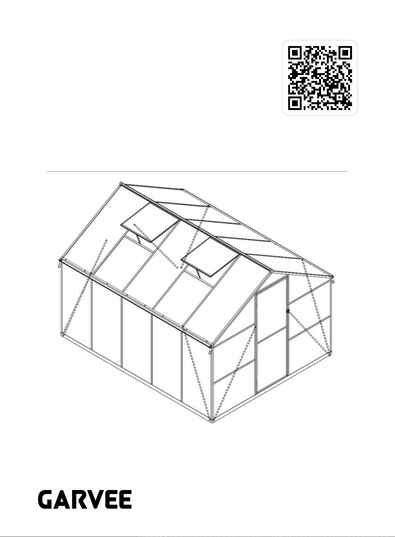
8*10FT Greenhouse
Product ID. 7AUMM
Scan for Support
support@garvee.com
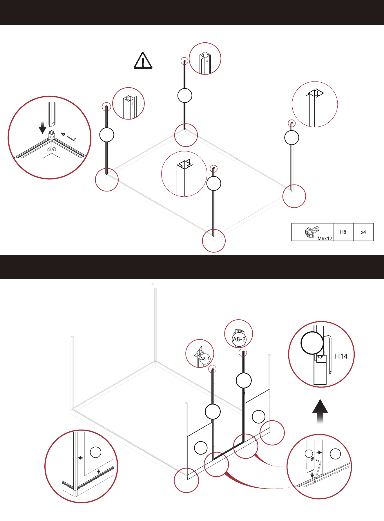
1
A25-1
C7
A25-2
A25-3
x4
x4
x
x8
1
A19
A26
A27
A28
A30-2
x4
x2
x1
x2
A31
x1
x8
x4
2
x4
x2
x2
x30
M6
x22
M6x30
x1
x82
M6x12
x4
x12
x1
x8
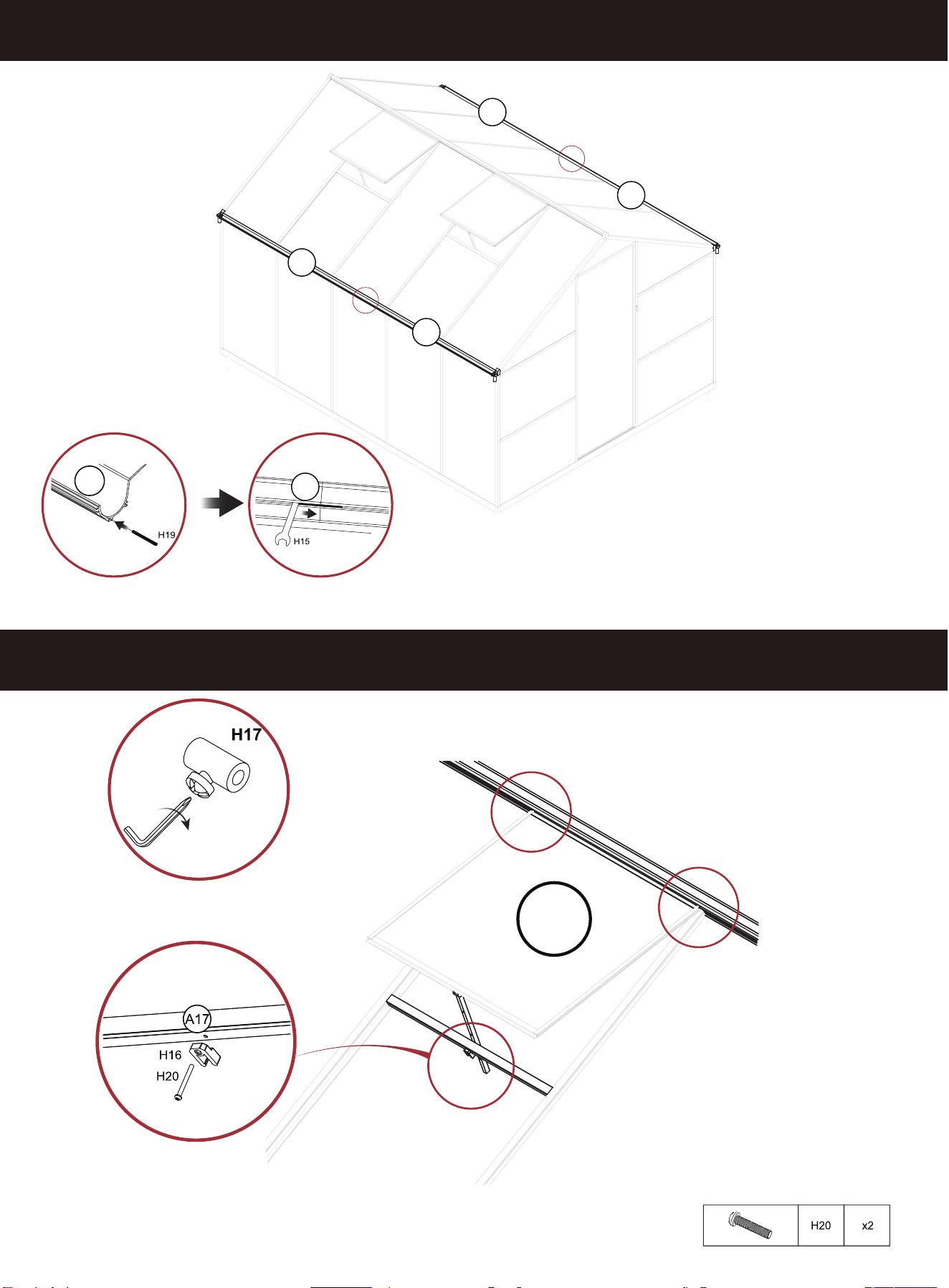
H15
H16
H17
H18
H19
H20
A30-1
C1
H4
H5
C5
x4
x2
x4
H
St5x10
x28
St4x10
St5x16
1
H2-1
H3-1
x8
H6
H7
H8
H9
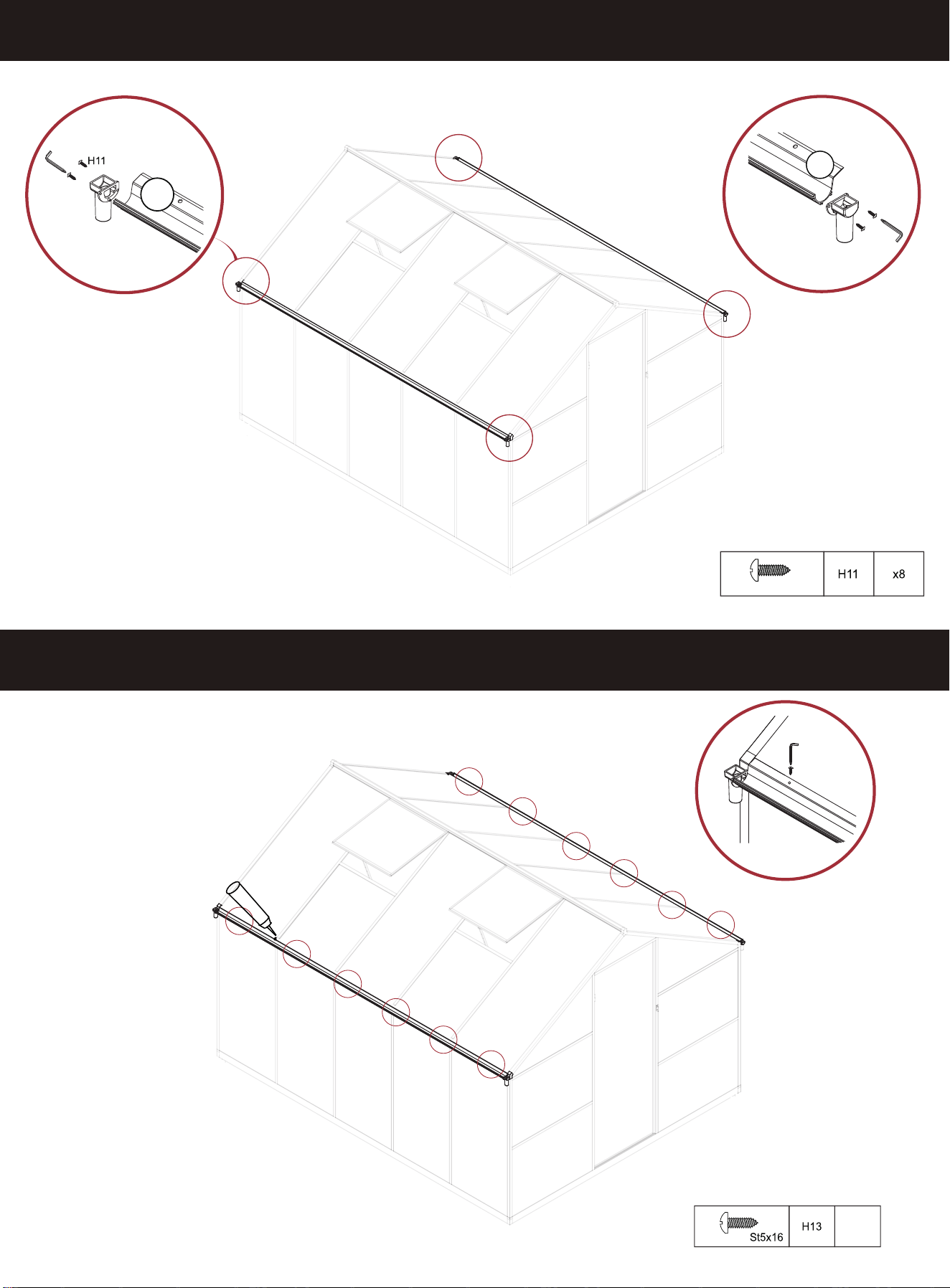
H11
H12
H13
H14
C6
F8
x1
x2
x4
x12
M6x2
0
x2
x2
M4x38
x2
x2
x2
x2
x8
C2
C3-1
F9
3
4
Qty.
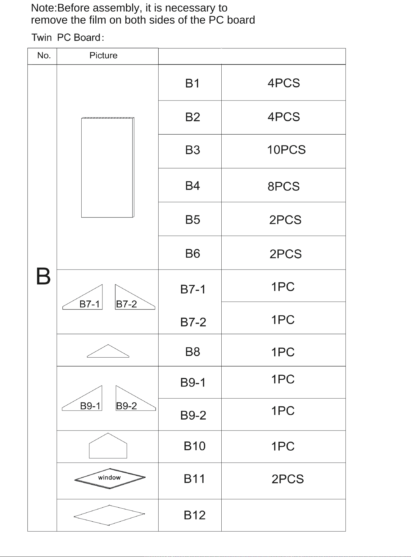
Note:Before assembly, it is necessary to
remove the film on both sides of the PC board;
1PC
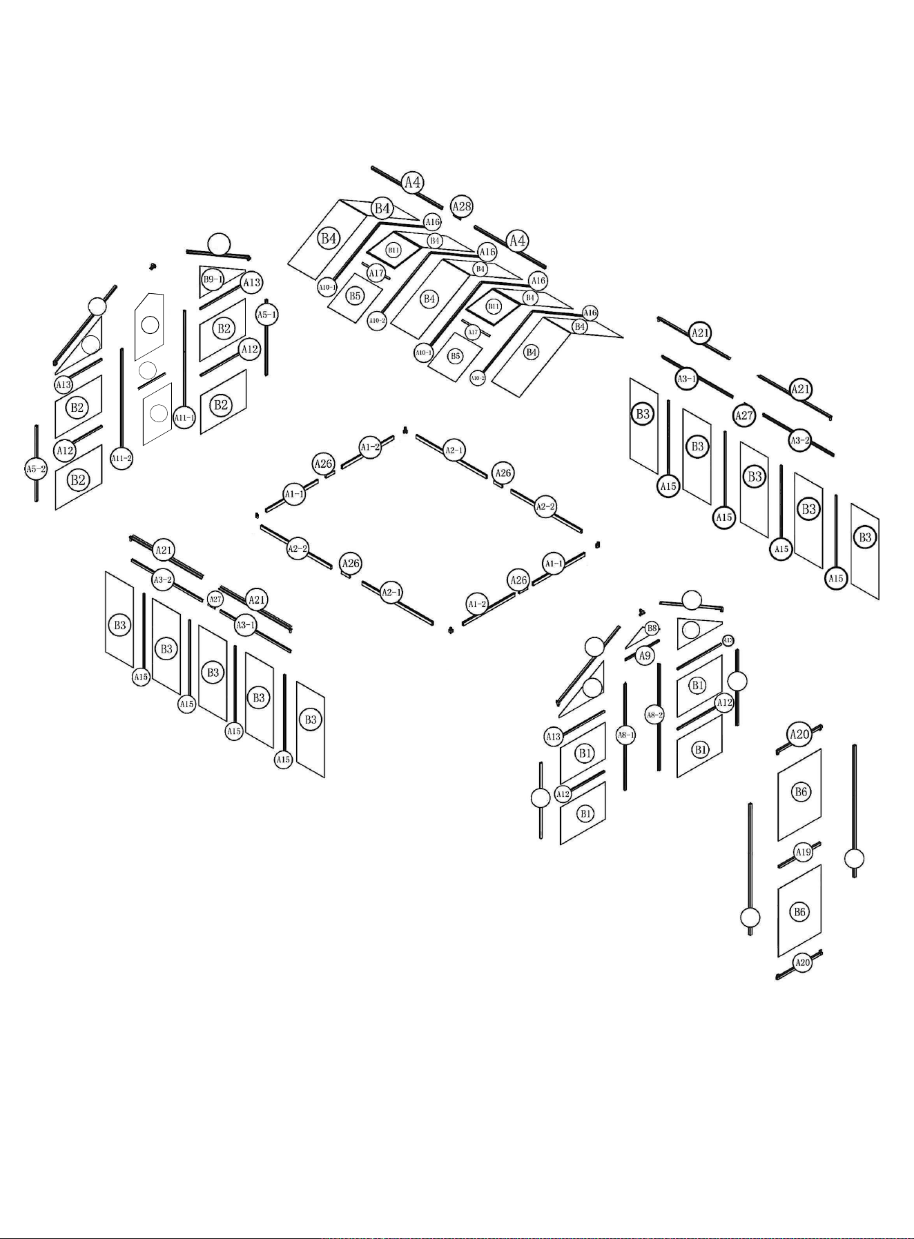
A6-1
A6-2
A5-1
A5-2
A18-1
A18-2
A7-2
A7-1
A9-2
B7-2
B7-1
B10
B12
A31
5
H3-1
H3-1
10
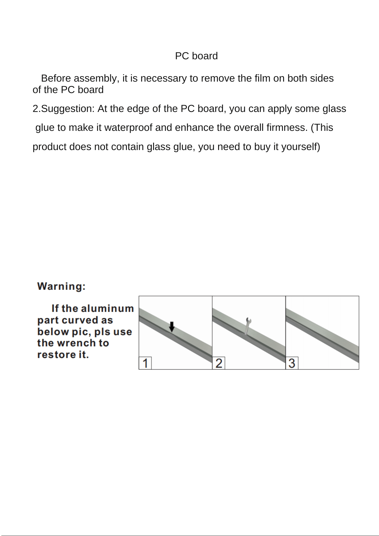
Please read the following carefully before assembling
Precautions for assembling the PC board:
1.Before assembly, it is necessary to remove the film on both sides
of the PC board;
2.Suggestion: At the edge of the PC board, you can apply some glass
glue to make it waterproof and enhance the overall firmness. (This
product does not contain glass glue, you need to buy it yourself)
When installing the C7, pay attention
C7 Please install the installation manual, if it is a cement floor, fix it
with expansion screw F8; The muddy ground is fixed with ground nail
F9.
Warning: Do not install in windy weather!
M6x30
M6
x
x8
8
H6
H9
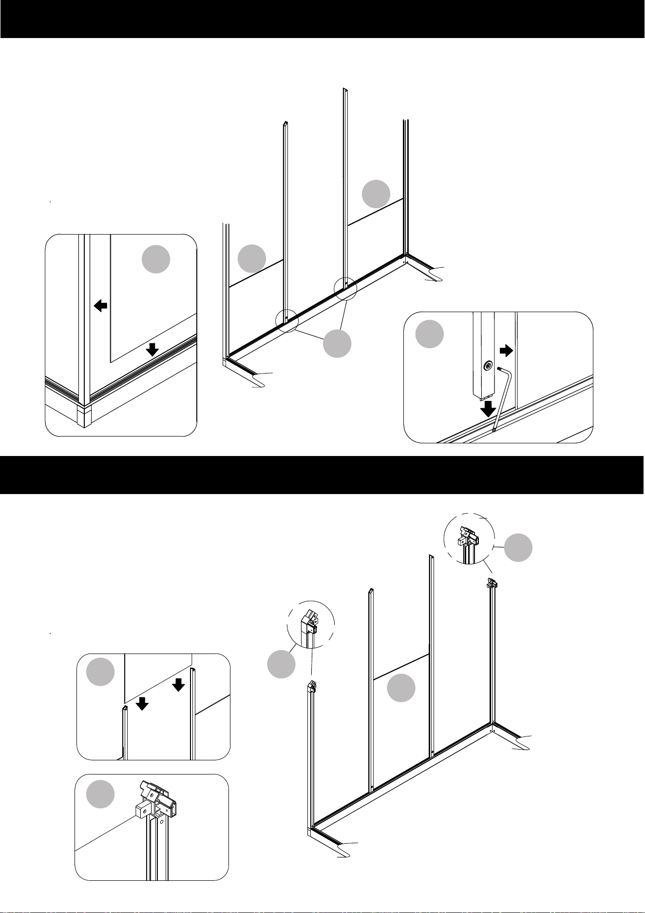
STEP 1
STEP 2
H1
H1X4
A26
M6x30
M6
x8
x8
x
8
Note:
A26 only needs to fix the first and fourth holes, and the middle two holes are
fixed when installing C7 in the next step,As shown in the figure below:
C7
C7
C7
C7
F9
F8
H9
H6
C7
C7 Please install the installation manual, if it is a cement floor,
fix it with expansion screw F8, as shown in Figure a; The muddy
ground is fixed with ground nail F9, as shown in Figure b:
x
F9
F8
H6
H9
8
a
b
H1
H1
H1
H1
7
Insert the ground
nail F9 bevel
x8
H8
M6x12
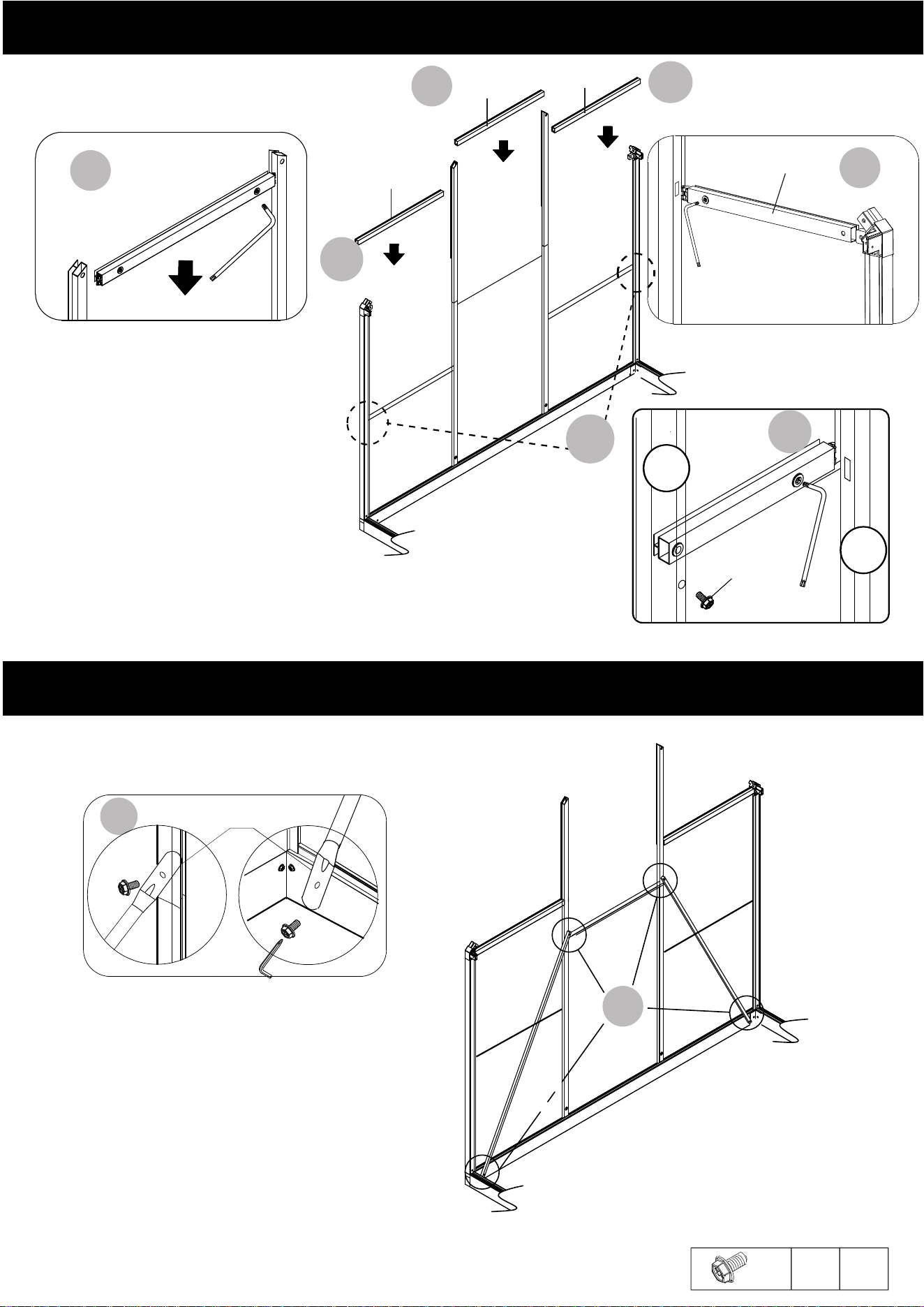
STEP 3
STEP 4
A5-1
A5-2
A5-2
A5-1
X4
A8-1
X2
A8-2
B1
B1
B1
A8
A8
B1
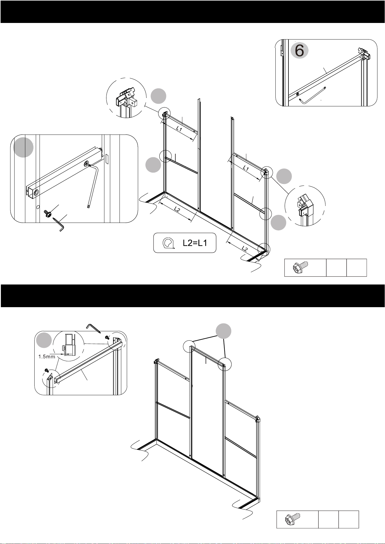
Please note the A5
orientation.
8
6
6
A13
A13
H2-1
H2-1
Do not tighten the H8 screws in step until
step 7 is successfully completed.
STEP5-6
A12
A12
x2
H8
M6x12
5
5
7
H8
7
H8
A9
H2-1
A13
H14
A9
STEP7
H7
A12
H14
H8
A8-2
A5-2
H7
9
5
x2
H8
M6x12
8
9-1
B7-1
9-2
B8
B8
B7-1
9-1
9-2
9-1
A9
B7-2
STEP8
A23
A23
x4
H8
M6x12
STEP9
8
A23
H8
H8
10
A6-1
A6-2
H3-1
H7
H7
H8
H8
M6x12
X
H8
4
H3-1
A6-2
A6-1
H8
C2
STEP10
11
11
11
12
A11-2
A11-1
11
B2
B2
12
B2
H14
14
13
13
14
14
B12
B12
H2-1
H2-1
H2-1
A11-1
Please press
the plate into
place before
locking it.
STEP11-12
STEP13-14
12
B12
17
A13
A13
A31
B2
B2
A23
A12
B2
A12
B2
A23
STEP15-16
STEP17
x6
H8
M6x12
13
A13
15-2
H13
16
15-2
15-2
16
A31
H13
15-1
A12
H14
H8
A5-2
A11-2
15-1
17
A23
H8
H8
A7-1
A7-2
B10
B9-2
B9-1
M6x12
H8 X4
H3-1
H8
H8
A7-2
A7-1
C2
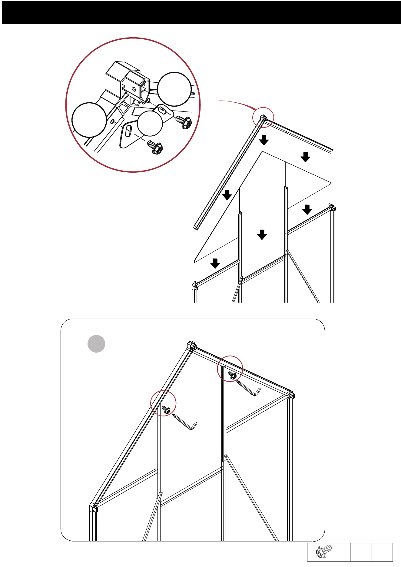
STEP18
H7
H7
H8
H8
18
14
STEP 19
A3
H8
H8
H12
A3 A3
H18
X4
C5
Install C3-1
C3-1
H12
C3-1
X8
X12
A3-2
A3-1
A3-1
A3-2
15
H9
X
H8
H18
H9
8
H18
C3-1
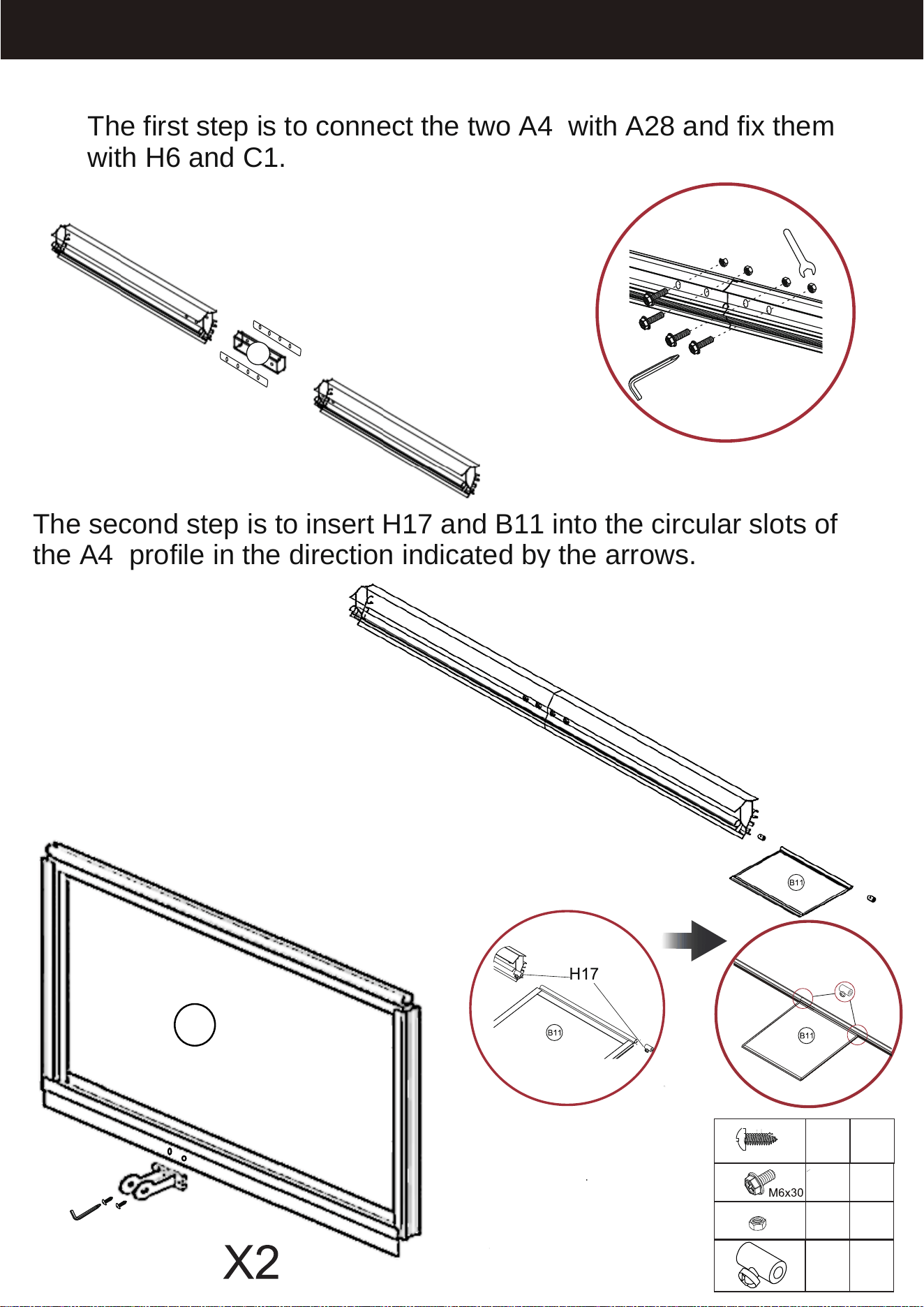
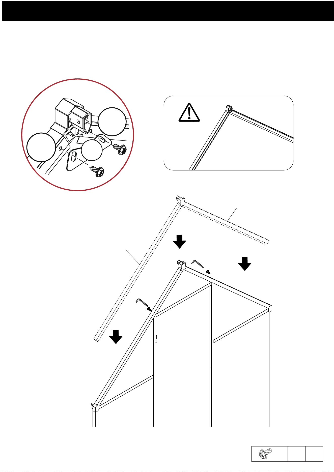
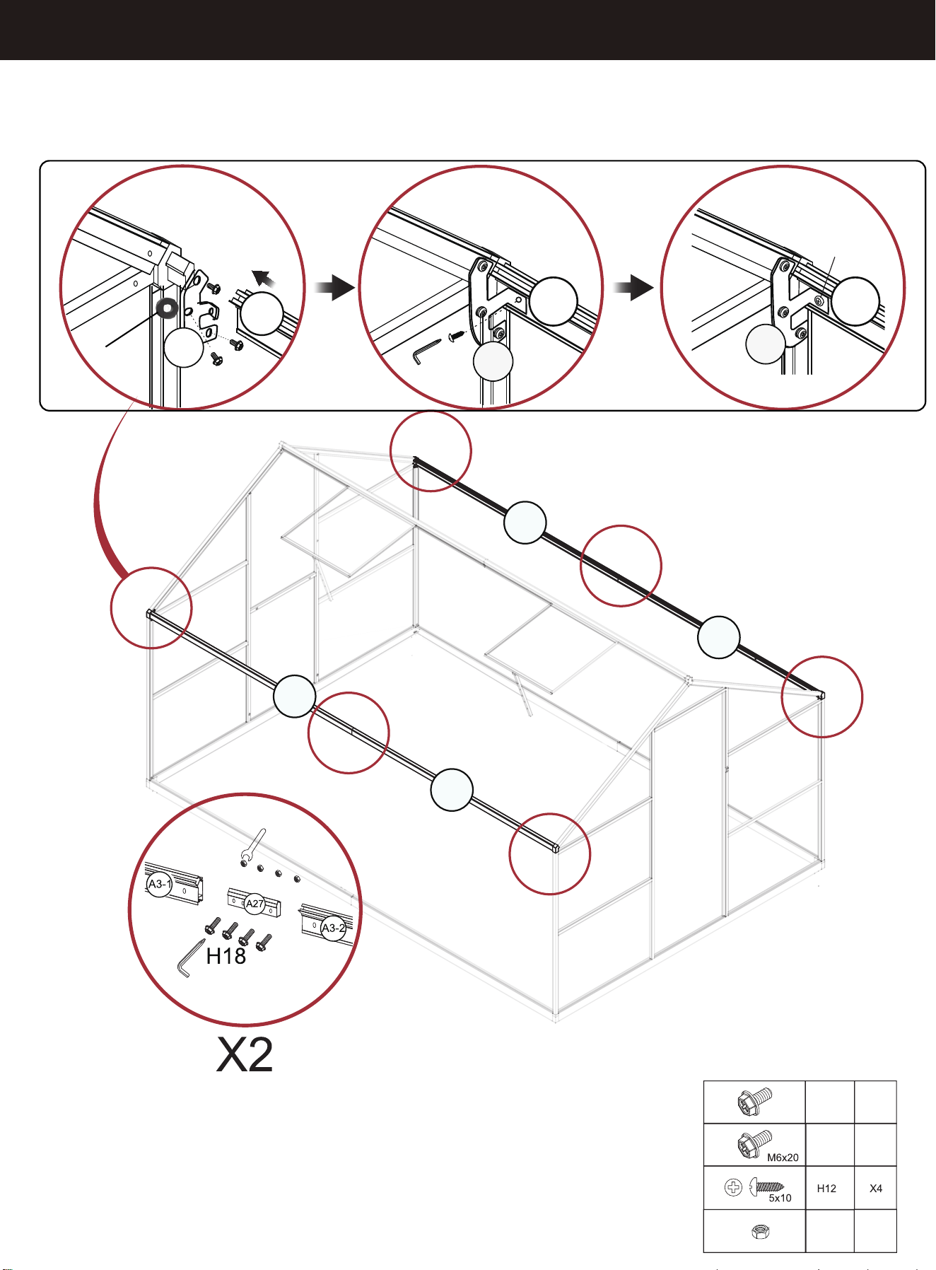
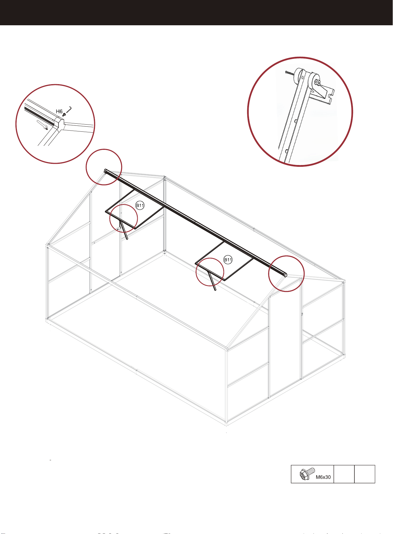
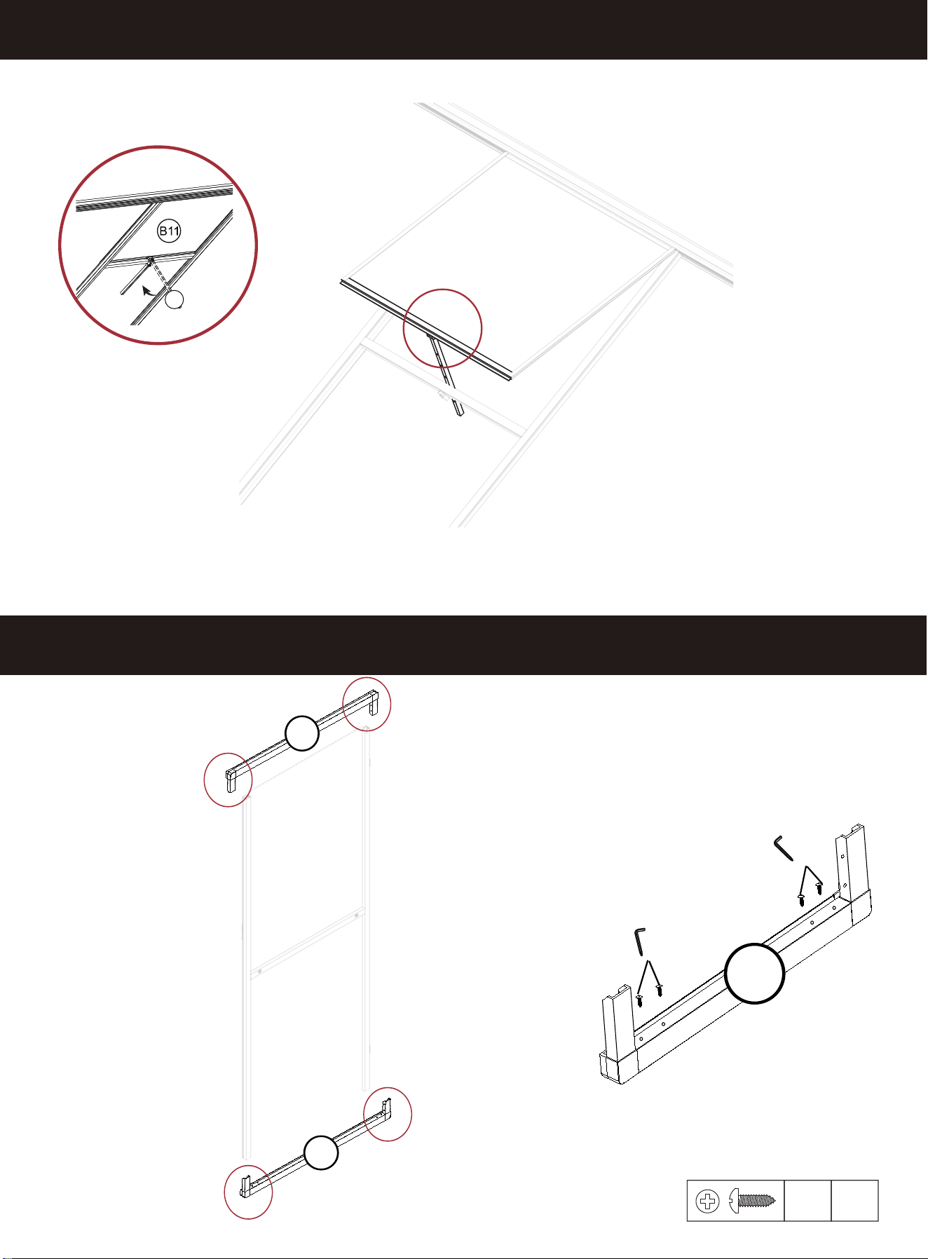
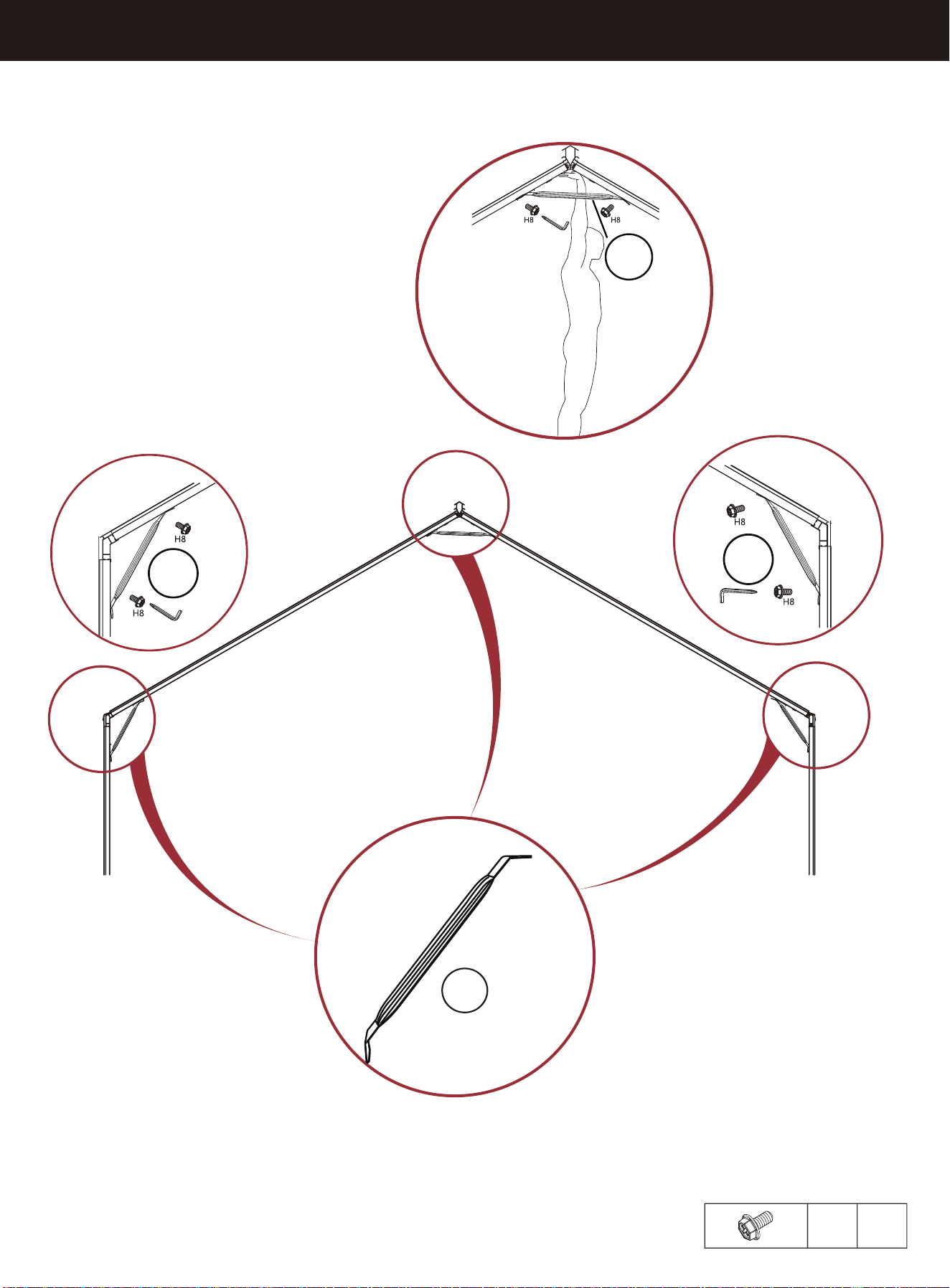
The second step is to insert H17 and B11 into the circular slots of
the A4 profile in the direction indicated by the arrows.
STEP 20
H6
H9
H7
H14
The first step is to connect the two A4 with A28 and fix them
with H6 and C1.
A4
A4
H17
A30-1
H11
H11
H6
H9
H17
x4
x4
x4
x4
St4x10
Note: The side of the B11 sunroof with
the UV label should be facing up.
C1
16
B11
A28
X2
STEP 21
A30-2
A30-1
H6
x2
17
STEP 22
B3
B3
B3
B3
B3
X4
B3
A15
A15
A15
A15
B3
A15
X4
B3
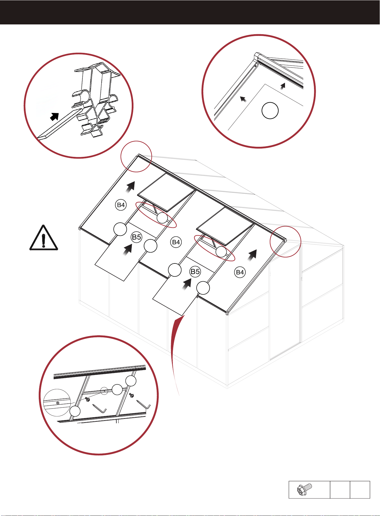
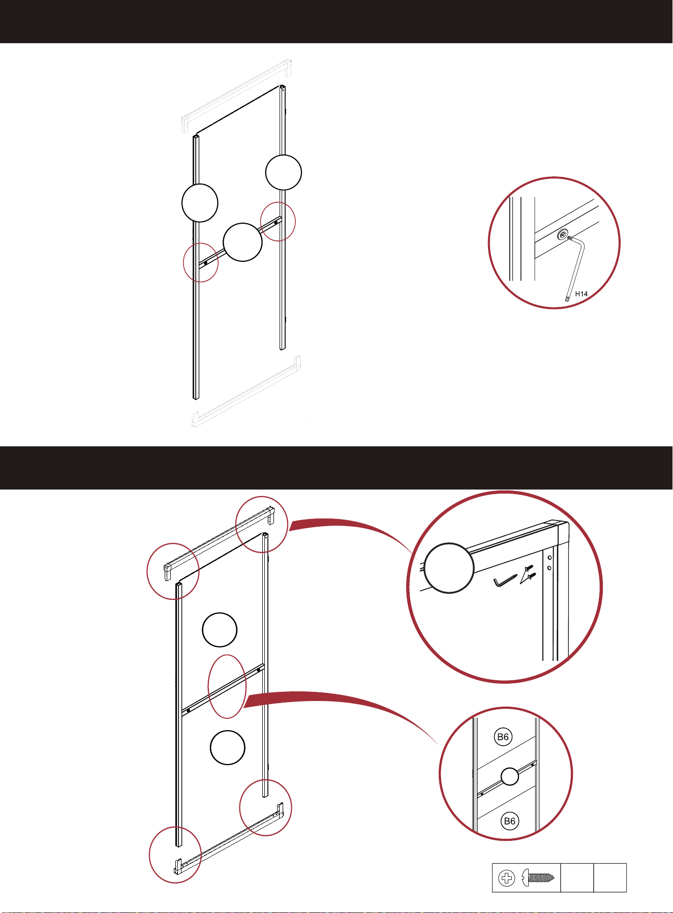
The installation position of PC board
B3 is shown in the figure (outside of
the aluminum profile)
18
After the other panels are
installed, this B3 is installed.
STEP 22
B3
B3
B3
B3
B3
B3
X4
B3
A15
X4
A15
A15
A15
A15
19
After the other panels are
installed, this B3 is installed.
STEP 23
A10-1
A17
A17
A10-2
A10-1
A10-2
H8
A17
A10-2
A10-1
B4
X2
M6x12
H8 X4
X2
B4
The position of the top beam
card slot of the
PC board B4 is shown in the figure
20
After the other panels are
installed, this B
5
is installed.
STEP 24
A16
B4
B4
A10(A16)
X4
X2
A16
A16
A16
21
After the other panels are
installed, this B4 is installed.
STEP 25
X2
A21
X2
H11
A21
H13
X12
X
STEP 26
12
St4X10
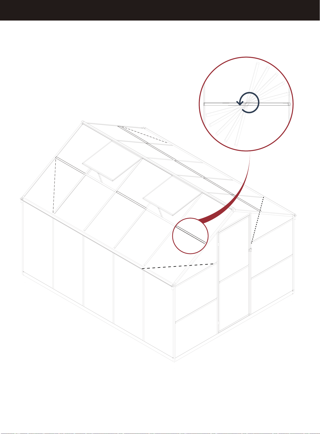
22
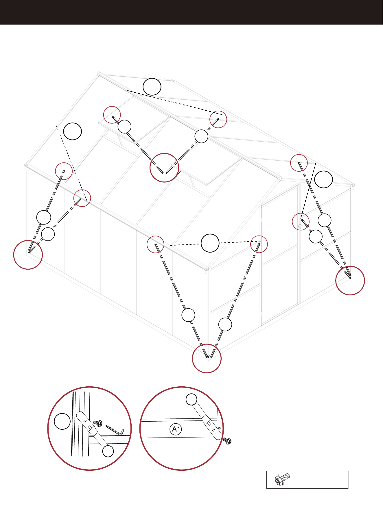
After each panel is installed
and the sink is secured,
apply some glass glue at
the junction of the panel
and the aluminum parts to
prevent water leakage and
strengthen stability.
STEP 28
STEP 27
A21
A21
X2 X2
B11
X2
X2
A21
M4x38
23
A21
A21
A21
STEP 30
STEP 29
H11
x8
A30-2
H7
H11
H4
H7
H11
H4
24
A20
A20
A20
STEP 32
STEP 31
X2
H11
x8
25
A18-2
A18-1
A19
B6
B6
H11
H7
A20
X4
A19
STEP 33
X2
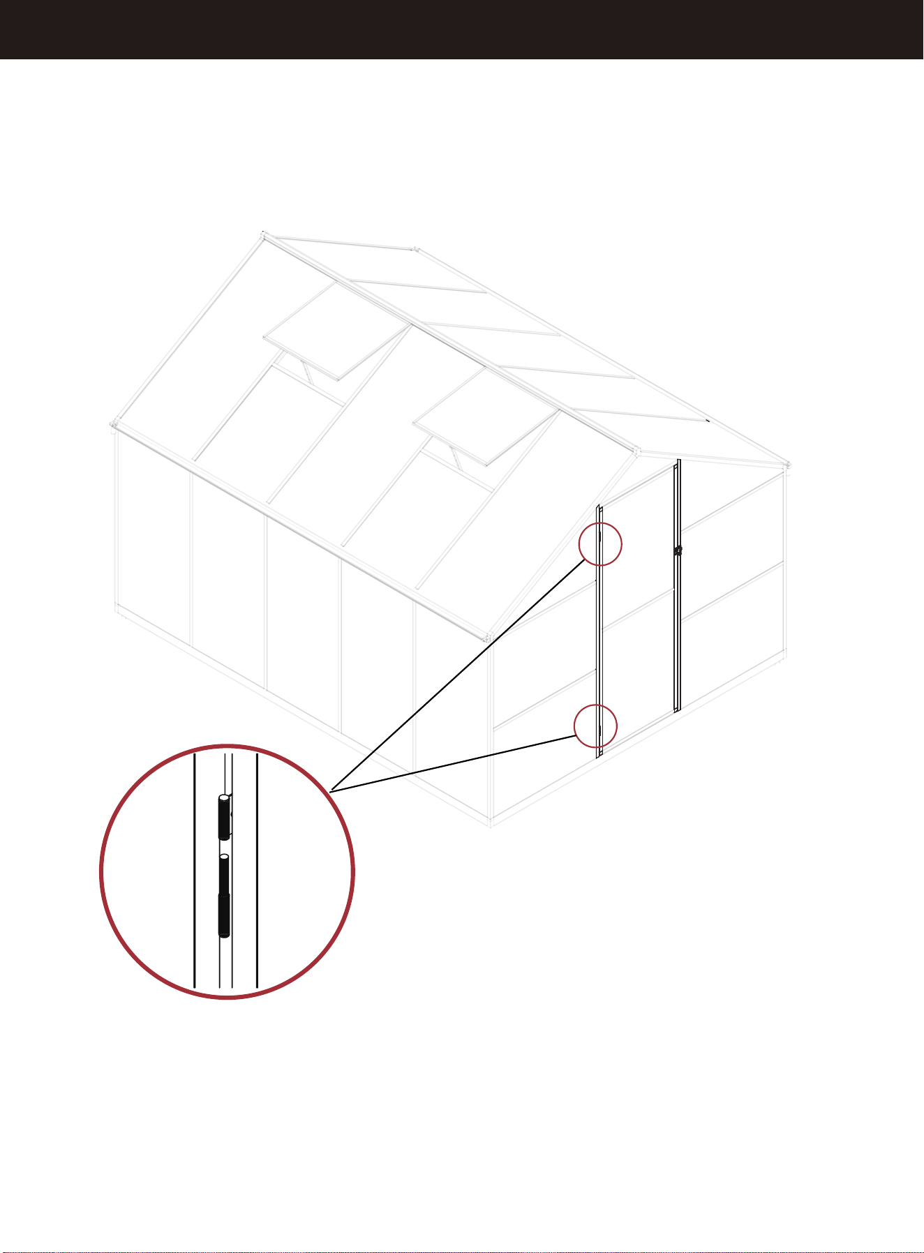
When installing the door, keep it open
26
STEP 34
A23
A23
A23
A23
A23
A23
A23
A5-1
M6x12
H8
X16
A23
A25-3
A25-3
A25-3
A25-3
H8
27
A23
A23
STEP 35
M6x12
H8
X24
X4
A25-2
A25-2
A25-1
A25-1
28
STEP 36
C6
29
