INSTALLATION MANUAL
TRUFIG for VX | VXQ Round and Square Speakers
page 1 of 3
336-0140 REV A
TRUFIG
INTRODUCTION
This installation guide will provide instructions to install a VX or VXQ speaker into a TRUFIG Gypsum Mounting
Platform for drywall, plaster, or wallpaper applications. This document will cover steps for wiring and installing the
speaker into the platform.
BOX CONTENTS
5/8” Gypsum Mounting Platform for Sonance Visual Experience Series VX and VXQ Speakers
REQUIRED HARDWARE
TRUFIG Gypsum or Solid Surface Mounting Platform for Sonance VX | VXQ speakers
Sonance VX or James VXQ Round or Square Speaker
Sonance VX or James VXQ Trimless Round or Square Grille
INSTALLING THE MOUNTING PLATFORM
To install and finish the VX | VXQ Mounting Platform, fol-
low the standard TRUFIG procedure for Gypsum (avail-
able at trufig.com).
WIRING FOR THE SPEAKER
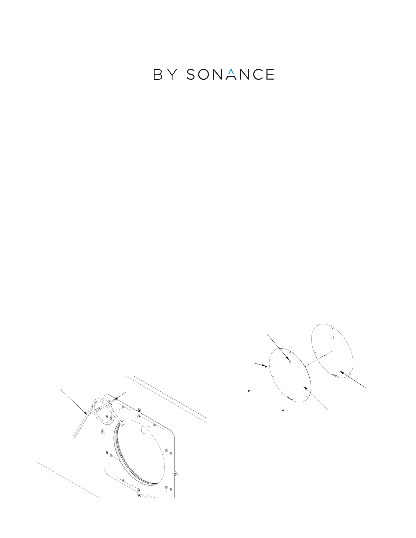
The Mounting Platform has a tie wrap installed on one of
the pierce bridges on the back. (fig. 1)
Use this to attach the speaker wire for retrieval after
installation.
NOTE: It is important to wire from the amp to the
speaker/mounting platform location and reserve the
wiring at the mounting platform BEFORE completing
the mud, sand, and paint for the surface.
INSTALLING THE SPEAKER
Proceed to these steps after the TRUFIG mounting plat-
form has been installed and the wall or ceiling surface
has been mudded, sanded.
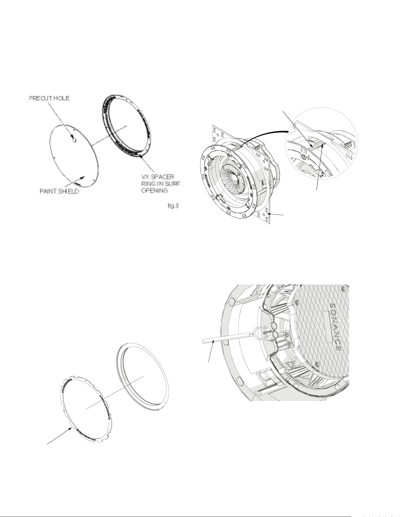
1. Locate the screws on the metal sanding shield and
remove them. Use the keyhole to remove the metal
sanding shied, being careful not to remove the plastic
paint shield. (fig. 2)
WIRE
ZIP TIE
fig.1
SCREWS
PAINT SHIELD
SANDING SHIELD
fig.3
KEY HOLE
page 2 of 3
2. After painting is complete, remove the paint shield from
the mounting platform opening. The paint shield is a
thin, plastic material that is secured around the pe-
rimeter with adhesive, so it should pull away from the
opening easily. The paint shield includes a pre-cut hole
to allow for easy removal using a finger or pointed ob-
ject like a screwdriver. Poke through and pull the paint
shield away from the surface. (fig. 3)
NOTE: The mounting platform opening includes a
small VX spacer ring that is secured around the rim
with adhesive. Removing the paint shield will reveal
the VX spacer ring. The spacer is labeled “VX SPAC-
ER REMOVE FOR VXQ.”
ReseRve oR Remove the vX spaceR Ring
1. When installing Sonance VX speaker models, leave the
spacer ring in place.
2. When installing James VXQ speaker models, this spacer
ring must be removed. (fig. 4)
3. Feel within the surface opening to locate the reserved
speaker wire. Free it from the back of the mounting
platform and pull it through to hang outside of the
opening.
FoR squaRe speakeR installations only:
1. Insert the VX or VXQ round speaker into the VX Square
Adapter
2. Align the square adapter alignment tabs with the slots
on the speaker and press the adapter to the speaker
until they are firmly together (fig. 5). This will allow the
grille to fit to the surface properly and ensure a level
placement.
connecting the speakeR
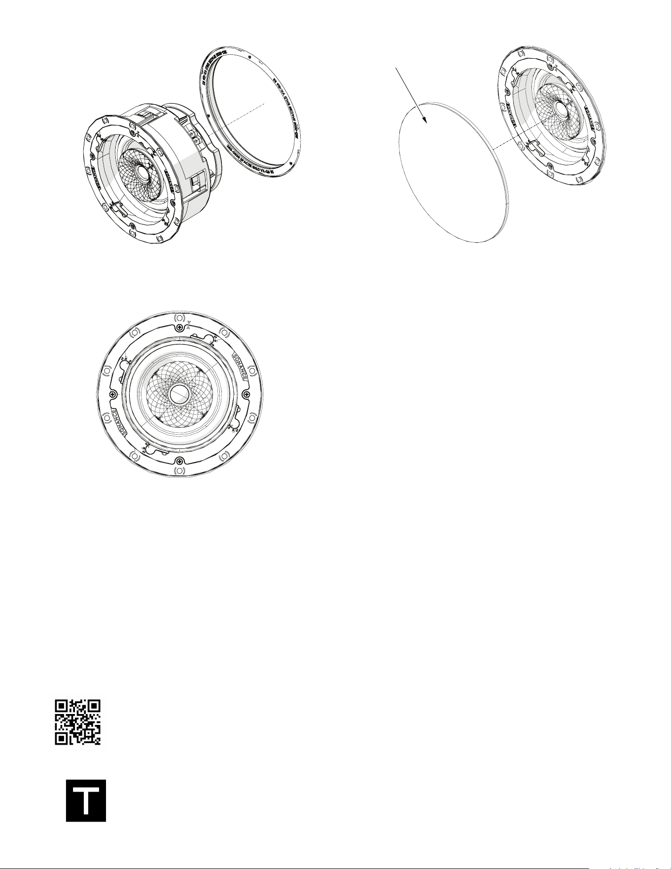
1. Connect the loose end of the speaker wire to the speak-
er before inserting the speaker into the surface opening.
(fig.6)
2. Insert and center the VX or VXQ speaker into the pre-
pared surface opening. Once centered gently secure
the toggle feet using a screwdriver or power drill with
torque set to the lowest setting (see VX or VXQ installa-
tion manual for detailed steps).
NOTE: Ensure that there is an even gap around
the speaker.
3. Place the grille onto the speaker and verify proper fit.
(fig.9)
VX SPEAKER
RING
fig. 4
SURFACE
OPENING
SQUARE ADAPTOR
SLOT
ALIGNMENT TAB
fig. 5
WIRE
fig. 6
page 3 of 3
Scan QR code for additional information and resources. For technical support call (949) 492-7777
or visit sonance.com/visual-experience
® 2024 SONANCE All rights reserved. TRUFIG is a registered trademark of Dana Innovations. Due to continuous product improvement, all features
and specifications are subject to change without notice. For the latest SONANCE and TRUFIG product specification information visit our website
at www.sonance.com.
991 Calle Amanecer - San Clemente, CA 92673 USA • Phone: 949.492.7777 • Fax: 949.361.5151 • Technical Support: 949.492.7777 • www.sonance.
com
4. If there is a need to re-center the speaker, remove the
grille and lightly loosen the toggle feet screws, re-cen-
ter, and tighten the toggle feet screws again.
g. 7
g. 8
GRILLE
fig. 9
