1
Instruction Manual
PRINTED 1115 197659-005
KEEP THIS MANUAL IN THE POCKET ON HEATER FOR FUTURE REFERENCE
WHENEVER MAINTENANCE ADJUSTMENT OR SERVICE IS REQUIRED.
COMMERCIAL GAS WATER HEATERS
• For Your Safety •
AN ODORANT IS ADDED TO THE GAS USED
BY THIS WATER HEATER.
INSTALLATION - OPERATION
- SERVICE - MAINTENANCE
PLACE THESE INSTRUCTIONS ADJACENT TO HEATER AND NOTIFY OWNER TO KEEP FOR FUTURE REFERENCE.
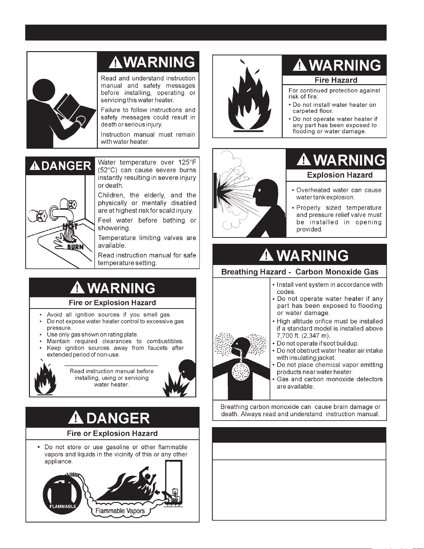
Read and understand this instruction
manual and the safety messages
herein before installing, operating or
servicing this water heater.
Failure to follow these instructions and
safety messages could result in death
or serious injury.
This manual must remain with the
water heater.
WARNING: If the information in these
instructions is not followed exactly, a fire
or explosion may result causing property
damage, personal injury or death.
Do not store or use gasoline or other
flammable vapors and liquids in the
vicinity of this or any other appliance.
WHAT TO DO IF YOU SMELL GAS:
Do not try to light any appliance.
Do not touch any electrical switch; do
not use any phone in your building.
Immediately call your gas supplier
from a neighbor’s phone. Follow the
gas supplier’s instructions.
If you cannot reach your gas supplier,
call the fire department.
Installation and service must be
performed by a qualified installer,
service agency or the gas supplier.
•
•
•
•
Low Lead Content

2
SAFE INSTALLATION, USE AND SERVICE......................3
APPROVALS ...................................................................... 3
GENERAL SAFETY INFORMATION .................................. 4
INTRODUCTION ................................................................ 5
Abbreviations Used ..................................................... 5
QualiedInstallerorServiceAgency........................... 5
PreparingfortheNewInstallation ............................... 5
INSTALLATION CONSIDERATIONS ............................. 6-9
RoughInDimensions .................................................. 6
Thermometers ............................................................. 7
FactstoConsiderAboutLocation ............................... 7
HighAltitude ................................................................ 8
Clearances .................................................................. 8
Insulation Blankets ...................................................... 9
Hard Water .................................................................. 9
CirculationPumps ....................................................... 9
INSTALLATION REQUIREMENTS .................................. 10
GasSupplySystems ................................................. 10
GasPressureRequirements ..................................... 10
SupplyGasRegulator ............................................... 10
MixingValves ............................................................10
WaterPiping .............................................................. 11
ClosedWaterSystems .............................................. 11
ThermalExpansion ................................................... 11
Temperature-PressureReliefValve ......................... 11
FillingtheWaterHeater ............................................. 12
AirRequirements....................................................... 12
UnconnedSpace ..................................................... 13
ConnedSpace ......................................................... 13
FreshAirOpeningsforConnedSpaces .................. 13
OutdoorAirThroughTwoOpenings .......................... 13
OutdoorAirThroughOneOpening ........................... 13
OutdoorAirThroughTwoHorizontalDucts ............... 14
OutdoorAirThroughTwoVerticalDucts ................... 14
AirFromOtherIndoorSpaces .................................. 14
Venting ...................................................................... 14
SupplyGasRegulator ............................................... 15
GasPiping ................................................................. 16
SedimentTraps ......................................................... 17
LIGHTING & OPERATING INSTRUCTIONS .............. 18,19
TEMPERATURE REGULATION ...................................... 20
FOR YOUR INFORMATION ............................................. 20
Start Up Conditions ................................................... 20
Operational Conditions .............................................. 21
PERIODIC MAINTENANCE ............................................. 22
VentingSystemInspection ........................................ 22
BurnerInspection ...................................................... 22
BurnerCleaning ........................................................ 22
Housekeeping ........................................................... 23
AnodeRodInspection ............................................... 23
Temperature-PressureReliefValveTest ................... 23
RECOMMENDED PROCEDURE FOR PERIODIC
REMOVAL OF LIME DEPOSITS FROM TANK
TYPE COMMERCIAL WATER HEATERS ........................ 23
DelimingSolvents...................................................... 24
TankCleanoutProcedure .......................................... 24
DelimingUsingFlo-JugMethod ................................ 24
DrainingandFlushing ............................................... 25
Service ...................................................................... 25
LEAKAGE CHECKPOINTS .............................................. 26
TROUBLESHOOTING GUIDELINES ............................... 27
WATER PIPING DIAGRAMS .......................................28-33
NOTES ............................................................................. 34
TABLE OF CONTENTS
3
SAFE INSTALLATION, USE AND SERVICE
Theproperinstallation,useandservicingofthiswaterheaterisextremelyimportanttoyoursafetyandthesafetyofothers.
Manysafety-relatedmessagesandinstructionshavebeenprovidedinthismanualandonyourownwaterheatertowarnyouand
othersofapotentialinjuryhazard.Readandobeyallsafetymessagesandinstructionsthroughoutthismanual.Itisveryimportant
thatthemeaningofeachsafetymessageisunderstoodbyyouandotherswhoinstall,use,orservicethiswaterheater.
Allsafetymessageswillgenerallytellyouaboutthetypeofhazard,whatcanhappenifyoudonotfollowthesafetymessage,and
howtoavoidtheriskofinjury.
DANGER
WARNING
CAUTION
CAUTION
DANGER indicates an imminently
hazardous situation which, if not avoided,
will result in injury or death.
This is the safety alert symbol. It is used to alert you to
potential personal injury hazards. Obey all safety
messages that follow this symbol to avoid possible
injury or death.
WARNING indicates a potentially hazardous
situation which, if not avoided, could result
in injury or death.
CAUTION indicates a potentially hazardous
situation which, if not avoided, could result in
minor or moderate injury.
CAUTION used without the safety alert
symbol indicates a potentially hazardous
situation which, if not avoided, could result in
property damage.
APPROVALS
Low Lead Content
4
GENERAL SAFETY INFORMATION
Improper installation, use and service may
result in property damage.
CAUTION
•
Do not operate water heater if any part has been
exposed to flooding or water damage.
•
Inspect anode rods regularly, replace when significantly depleted.
•
Install in location with drainage.
•
Fill tank with water before operation.
•
Properly sized thermal expansion tanks are required on all
closed water systems.
Refer to this manual for installation and service.

5
ThankYouforpurchasingthiswaterheater.Properlyinstalledand
maintained,itshouldgiveyouyearsoftroublefreeservice.
ABBREVIATIONS USED
AbbreviationsFoundInThisInstructionManual:
• UL-UnderwritersLaboratoriesInc.
• ANSI-AmericanNationalStandardsInstitute
• NFPA-NationalFireProtectionAssociation
• ASME-AmericanSocietyofMechanicalEngineers
• AHRI-Air-Conditioning,HeatingandRefrigerationInstitute
• CAN - Canada
• EPACT-EnergyPolicyAct
• CSA-CanadianStandardsAssociation
This gas-fired water heater is design certified by Underwriters
LaboratoriesInc.underAmericanNationalStandard/CSAStandard
forGasWaterHeatersANSIZ21.10.3•CSA4.3(currentedition).
QUALIFIED INSTALLER OR SERVICE AGENCY
Installationandserviceofthiswaterheaterrequiresabilityequivalent
tothatofaQualiedAgency(asdenedbyANSIbelow)intheeld
involved. Installation skills such as plumbing, air supply, venting,
gassupplyandelectricalsupplyarerequiredinadditiontoelectrical
testingskillswhenperformingservice.
ANSIZ223.12006Sec.3.3.83:“QualiedAgency”-“Anyindividual,
rm, corporation or company that either in person or through a
representativeisengagedinandisresponsiblefor(a)theinstallation,
testingorreplacementofgaspipingor(b)theconnection,installation,
testing, repair or servicing of appliances and equipment; that is
experiencedinsuchwork;thatisfamiliarwithallprecautionsrequired;
and that has complied with all the requirements of the authority
havingjurisdiction.”
If you are not qualied (as dened byANSI above) and licensed or
certied as required by the authority having jurisdiction to perform a
giventaskdonotattempttoperformanyoftheproceduresdescribed
inthismanual.Ifyoudonotunderstandtheinstructionsgiveninthis
manualdonotattempttoperformanyproceduresoutlinedinthismanual.
PREPARING FOR THE INSTALLATION
1. Readthe “GeneralSafety”section, page4ofthismanual
firstandthentheentiremanualcarefully.Ifyoudon’tfollow
thesafetyrules,thewaterheaterwillnotoperateproperly.
ItcouldcauseDEATH,SERIOUSBODILYINJURYAND/OR
PROPERTY DAMAGE.
This manual containsinstructions fortheinstallation,
operation,andmaintenanceofthegas-firedwaterheater.It
alsocontainswarningsthroughoutthemanualthatyoumust
readandbeawareof.Allwarningsandallinstructionsare
essentialtotheproperoperationofthewaterheaterandyour
safety.Sincewecannotputeverythingonthefirstfewpages,
READ THE ENTIRE MANUAL BEFORE ATTEMPTING TO
INSTALL OR OPERATE THE WATER HEATER.
2.Theinstallation mustconformwiththeseinstructionsand
thelocalcodeauthorityhavingjurisdiction.Intheabsence
oflocalcodes,theinstallationmustcomplywiththecurrent
editions of the National Fuel Gas Code, ANSI Z223.1/
NFPA54orCAN/CSA-B149.1theNaturalGasandPropane
Installation Code. All documents are available from the
CanadianStandardsAssociation,8501EastPleasantValley
Road, Cleveland, OH 44131. NFPA documents are also
available from the National Fire Protection Association, 1
BatterymarchPark,Quincy,MA02269.
3.If after readingthismanualyouhaveany questionsor do
notunderstandanyportionoftheinstructions,callthelocal
gasutilityorthemanufacturerwhosenameappearsonthe
ratingplate.
4.Carefully plan the place where you are going to put the
water heater. Correct combustion,vent action, and vent
pipeinstallationareveryimportantinpreventingdeathfrom
possiblecarbonmonoxidepoisoningandfires,seeFigures
3 and 7.
Examinethelocationtoensurethewaterheaterc omplieswith
the“LocatingtheNewWaterHeater”sectioninthismanual.
5.ForCaliforniainstallationthiswaterheatermustbebraced,
anchored, or strapped to avoid falling or moving during
an earthquake. Seeinstructions forcorrectinstallation
procedures.InstructionsmaybeobtainedfromCalifornia
Office of the State Architect, 400 P Street, Sacramento,
CA 95814.
6.MassachusettsCoderequiresthiswaterheatertobeinstalled
in accordance with Massachusetts 248-CMR 2.00: State
PlumbingCodeand248-CMR5.00.
INTRODUCTION
6
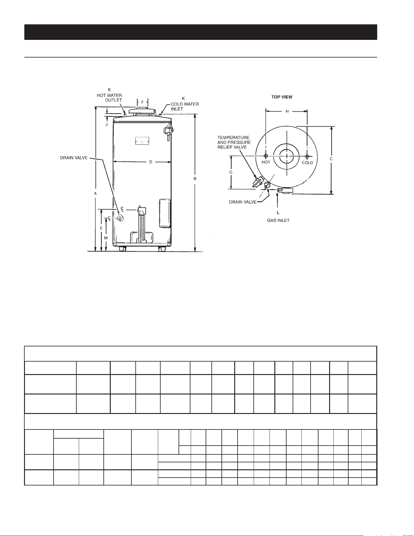
ROUGH IN DIMENSIONS
TABLE 1. DIMENSIONS AND RECOVERY RATINGS
DIMENSIONS
Model Units A B C D E F G H J K L M
75
Natural & LP
Inches
CM
611/8
155.25
581/2
148.6
2911/16
75.4
261/2
67.3
153/16
38.6
4
10.2
141/2
39.4
16
40.6
11/4
3.2
1
NPT
1/2
NPT
1115/16
30.3
100
Natural & LP
Inches
CM
685/8
174.3
661/2
168.9
3015/16
78.59
273/4
70.5
153/16
38.6
4
10.2
153/4
40.0
16
40.6
11/4
3.2
11/4
NPT
1/2
NPT
1115/16
30.3
RECOVERY RATINGS
Model
Input
Approx.
Gal.
Cap.
Approx.
Liter
Cap.
Temp.
Rise
C° 17 22 28 33 39 44 50 56 61 67 72 78
Rating
Btu/Hr
Rating
kW
F° 30 40 50 60 70 80 90 100 110 120 130 140
75 75,100 22 74 280
GPH 243 182 146 121 104 91 81 73 66 61 56 52
LPH 916 686 550 456 392 343 305 275 249 230 211 196
100 75,100 22 98 371
GPH 243 182 146 121 104 91 81 73 66 61 56 52
LPH 916 686 550 456 392 343 305 275 249 230 211 196
Recoveryratingsbasedon80%thermalefciency.
INSTALLATION CONSIDERATIONS
FIGURE 1.
7
THERMOMETERS (Not Supplied)
Thermometersshouldbeobtainedandeldinstalled.
Thermometersareinstalledinthesystemasameansofdetecting
thetemperatureoftheoutletwatersupply.
ThisWaterHeaterhasbeendesigncertifiedascomplyingwith
ANSIZ21.10.3-CSA4.3currenteditionforwaterheatersandis
consideredsuitablefor:
Water (Potable) Heating and Space Heating:All models are
consideredsuitableforwater(potable)heatingandspaceheating.
HOTTERWATERCANSCALD:
Waterheatersareintendedtoproducehotwater.Waterheatedtoa
temperaturewhichwillsatisfyspaceheating,clotheswashing,dish
washing,andothersanitizingneedscanscaldandpermanentlyinjure
youuponcontact.Somepeoplearemorelikelytobepermanently
injuredbyhotwaterthanothers.Theseincludetheelderly,children,
theinrm,orphysically/mentallyhandicapped.Ifanyoneusinghot
waterinyourhometsintooneofthesegroupsorifthereisalocal
coderequiringacertaintemperaturewateratthehotwatertap,then
youmusttakespecialprecautions.Inadditiontousingthelowest
possible temperature setting that satises your hot water needs,
ameanssuchasa*MixingValveshouldbeusedatthehotwater
tapsusedbythesepeopleoratthewaterheater.Mixingvalvesare
availableatplumbingsupplyorhardwarestores.Consultaqualied
installer or service agency. Follow mixing valve manufacturer’s
instructions for installation of valves. Beforechanging the factory
settingonthethermostat,readthe“TemperatureRegulation”section
inthismanual,seeFigures17and18.
FACTS TO CONSIDER ABOUT THE LOCATION
Carefully choose an indoor location for the newwater heater,
because the placement is a very important consideration for
the safety of the occupants in the building and for the most
economical use of the water heater. This water heater is not
foruseinmanufactured(mobile)homesoroutdoorinstallation.
Whetherreplacinganoldwaterheaterorputtingthewaterheater
inanewlocation,thefollowingcriticalpointsmustbeobserved:
1.Selectalocationindoorsascloseaspracticaltothegasventor
chimneytowhichthewaterheaterventisgoingtobeconnected,
andascentralizedwiththewaterpipingsystemaspossible.
2.Selected location must provide adequate clearances for
servicingandproperoperationofthewaterheater.
Installationofwaterheatermustbeaccomplishedinsuchamannerthat
ifthetankoranyconnectionsshouldleak,owwillnotcausedamageto
thestructure.Forthisreason,itisnotadvisabletoinstallwaterheater
inanatticorupperoor.Whensuchlocationscannotbeavoided,a
suitablemetaldrainpanshouldbeinstalledunderthewaterheater.
MetalDrainpansareavailableatyourlocalhardwarestore.Sucha
metaldrainpanmusthaveaminimumlengthandwidthofatleast
2”(51mm)greaterthanwaterheaterdimensionsandmustbepiped
toanadequatedrain.Thepanmustnotrestrictcombustionairow.
Waterheaterlifedependsuponwaterquality,waterpressureandthe
environmentinwhichthewaterheaterisinstalled.Waterheatersare
sometimesinstalledinlocationswhereleakagemayresultinproperty
damage,evenwiththeuseofadrainpanpipedtoadrain.However,
unanticipateddamagecanbereducedorpreventedbyaleakdetector
orwatershut-offdeviceusedinconjunctionwithapipeddrainpan.
Thesedevicesareavailablefromsomeplumbingsupplywholesalers
andretailers,anddetectandreacttoleakageinvariousways:
• Sensorsmountedinthedrainpanthattriggeranalarmorturnoff
theincomingwatertothewaterheaterwhenleakageisdetected.
• Sensorsmountedinthedrainpanthatturnoffthewatersupply
totheentirehomewhenwaterisdetectedinthedrainpan.
• Watersupplyshut-offdevicesthatactivatebasedonthewater
pressuredifferentialbetweenthecoldwaterandhotwaterpipes
connectedtothewaterheater.
• Devicesthatwillturnoffthegassupplytoagaswaterheater
whileatthesametimeshuttingoffitswatersupply.
INSTALLATIONS IN AREAS WHERE FLAMMABLE LIQUIDS
(VAPORS)ARELIKELYTOBEPRESENTORSTORED(GARAGES,
STORAGEANDUTILITYAREAS,ETC.):Flammableliquids(suchas
gasoline,solvents,propane[LPorbutane,etc.]andothersubstances
suchasadhesives,etc.)emitammablevaporswhichcanbeignitedby
agaswaterheater’spilotlightormainburner.Theresultingashback
andrecancausedeathorseriousburnstoanyoneinthearea,aswell
aspropertydamage.Ifinstallationinsuchareasisyouronlyoption,then
installationmustbeaccomplishedinawaythatthepilotameandmain
burnerameareelevatedfromooratleast18inches.Whilethismay
reducechancesofammablevapors,fromaoorspillbeingignited,
gasolineandotherammablesubstancesshouldneverbestoredor
8
usedinthesameroomorareacontainingagaswaterheaterorother
openameorsparkproducingappliance.NOTE:Flammablevaporsmay
bedrawnbyaircurrentsfromotherareasofthestructuretotheappliance.
Also,the waterheater mustbe located and/orprotected soit isnot
subjecttophysicaldamagebyamovingvehicle.
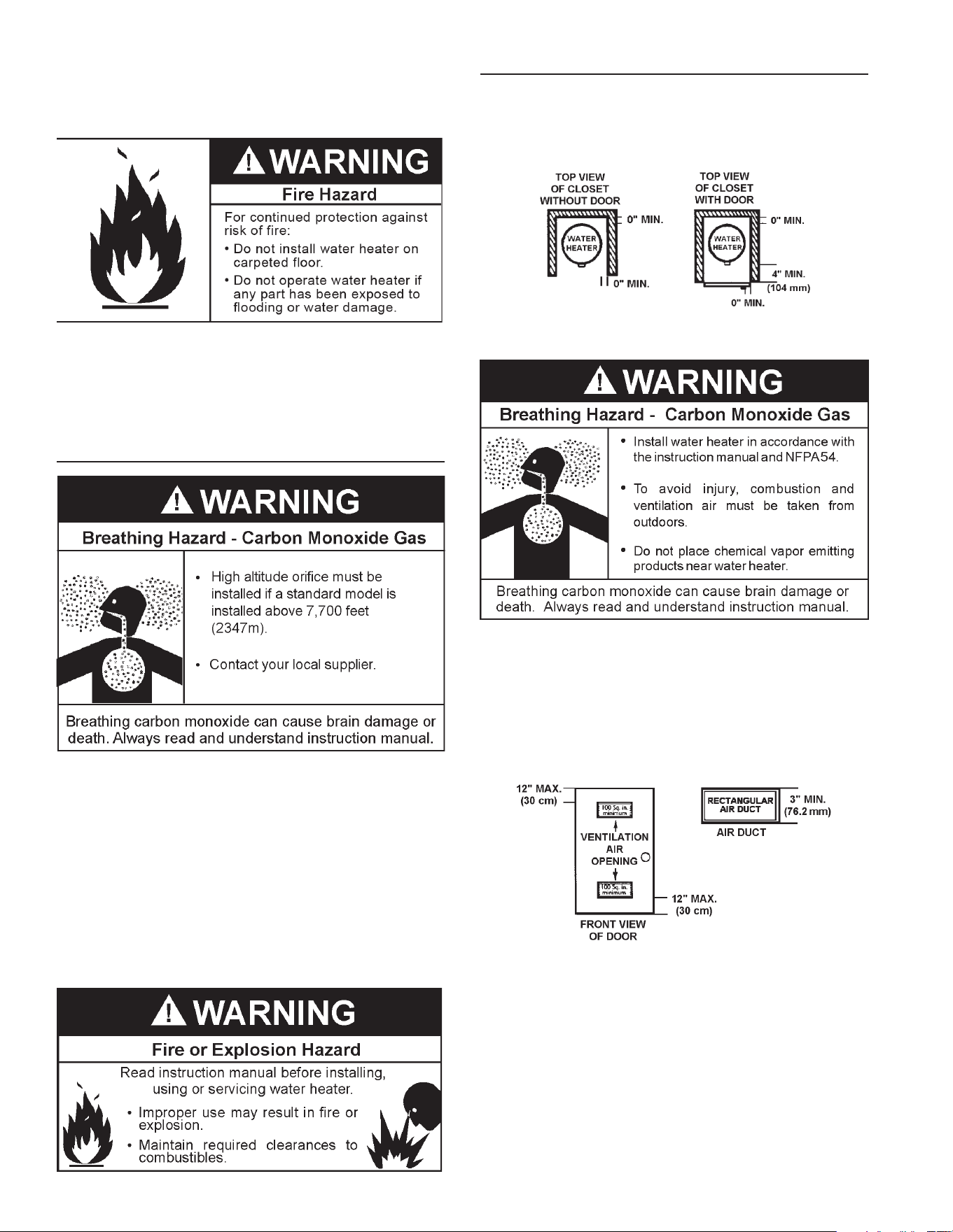
Thiswaterheatermustnotbeinstalleddirectlyoncarpeting.Carpeting
mustbeprotectedbymetalorwoodpanelbeneaththewaterheater
extendingbeyondthefullwidthanddepthofthewaterheaterbyatleast
3”(76.2mm)inanydirection,orifthewaterheaterisinstalledinan
alcoveorcloset,theentireoormustbecoveredbythepanel.Failure
toheedthiswarningmayresultinarehazard.
HIGH ALTITUDE
Waterheaterscoveredinthismanualhavebeentestedandapproved
forinstallation at elevations up to7,700 feet (2,347 m) abovesea
level.Forinstallationabove7,700feet(2,347m),thewaterheater’s
Btuinputshouldbereducedattherateof4percentforeach1,000
feet(305m)abovesealevelwhichrequiresreplacementoftheburner
oriceinaccordancewiththeNationalFuelGasCodeANSIZ223.1/
NFPA54 orthe NaturalGasandPropaneInstallationCodeCAN/
CSAB149.1.Contactyourlocalgassupplierforfurtherinformation.
Failuretoreplacethestandardoricewiththeproperhighaltitude
orice when installed at elevations above 7,700 feet (2,347 m)
couldresultinimproperandinefcientoperationofthewaterheater,
producingcarbonmonoxidegasinexcessofthesafelimits.This
couldresultinseriousinjuryordeath.Contactyourlocalgassupplier
foranyspecicchangesthatmayberequiredinyourarea.
CLEARANCES
Minimum clearances between the water heater and combustible
constructionare0inchatthesidesandrear,4”(102mm)atthe
front,and6”(153mm)fromtheventpipe.Clearancefromthetop
ofthejacketis12”(305mm)onmostmodels.
FIGURE 2.
A gas water heater cannot operate properly without the correct
amountofairforcombustion.Donotinstallinaconnedareasuch
asacloset,unlessyouprovideairasshowninthe“LocatingThe
NewWaterHeater”section.Neverobstructtheowofventilation
air.Ifyouhaveanydoubtsorquestionsatall,callyourgassupplier.
Failuretoprovidetheproperamountofcombustionaircanresult
in a re or explosion and cause death, serious bodily injury, or
propertydamage.
FIGURE 3.
Ifthiswaterheaterwillbeusedinbeautyshops,barbershops,
cleaning establishments,or self-servicelaundries withdry
cleaning equipment, it is imperative that the water heater or
water heaters beinstalled so thatcombustionandventilation
airbetakenfromoutsidetheseareas.
Propellantsofaerosolspraysandvolatilecompounds,(cleaners,
chlorinebasedchemicals,refrigerants,etc.)inadditiontobeing
highlyammableinmanycases,willalsochangetocorrosive
hydrochloricacidwhenexposedtothecombustionproductsof
thewaterheater.Theresultscanbehazardous,andalsocause
productfailure.
9
INSULATION BLANKETS
Do not obstruct water heater air intake
with insulating blanket.
Gas and carbon monoxide detectors
are available.
Install water heater in accordance with
the instruction manual.
Breathing carbon monoxide can cause brain damage or
death. Always read and understand instruction manual.
Breathing Hazard - Carbon Monoxide Gas
Insulation blankets are available to the general public for
external use on gas water heaters but are not necessary
with these products. The purpose of an insulation blanket is
to reduce the standby heat loss encountered with storage
tankheaters.Thewaterheaterscoveredbythismanualmeet
or exceed the Energy Policy Act standards with respect to
insulation and standby heat loss requirements, making an
insulationblanketunnecessary.
Should you choose to apply an insulation blanket to this
heater,youshouldfollowtheseinstructions.SeetheFeatures
and Components section of this manual for identification
of components mentioned below. Failure to follow these
instructions can restrict the air flow required for proper
combustion,potentiallyresulting infire,asphyxiation,serious
personalinjuryordeath.
• DO NOTapplyinsulationtothetopofthewaterheater,as
thiswillinterferewithsafeoperationofthedrafthood.
• DO NOTcoverthethermostatortheTemperature-
PressureReliefValve.
• DO NOTallowtheinsulationtocomewithin2inches(5
cm)ofthefloortopreventblockageofcombustionairflow
totheburner.
• DO NOTcovertheinstructionmanual.Keepitontheside
ofthewaterheaterornearbyforfuturereference.
• DOobtainnewwarningandinstructionlabelsfromthe
manufacturerforplacementontheblanketdirectlyover
theexistinglabels.
• DOinspecttheinsulationblanketfrequentlytomake
certainitdoesnotsag,therebyobstructingthe
combustionairflow.
HARD WATER
Wherehardwaterconditionsexist,watersofteningorthethreshold
type of water treatment is recommended. This will protect the
dishwashers,coffeeurns,waterheaters,waterpipingandother
equipment. See the Maintenance Section in this manual for
sedimentandlimescaleremovalprocedures.
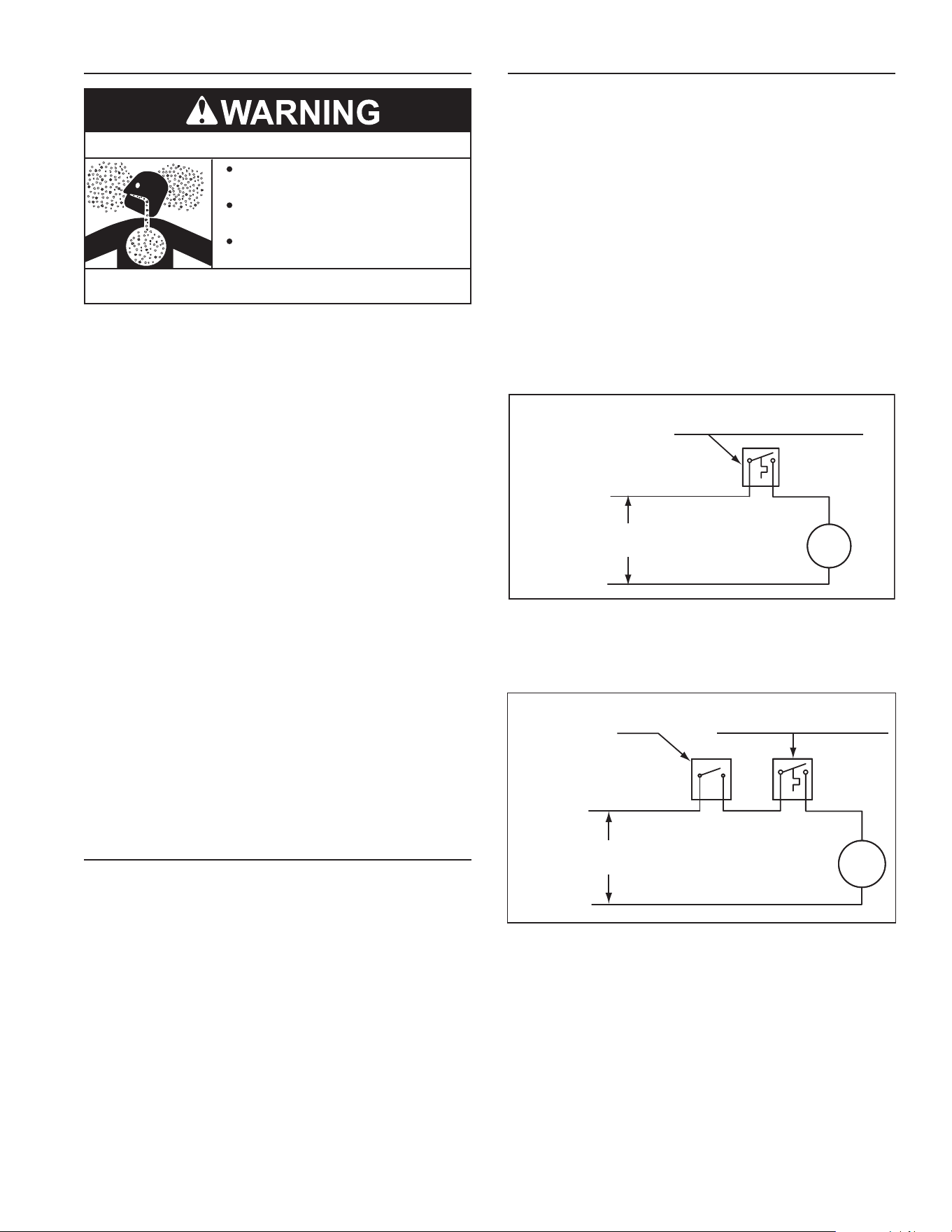
CIRCULATION PUMPS
Acirculatingpumpisusedwhenasystemrequiresacirculating
loop or there is a storage tank used in conjunction with the
water heater. See Water Piping Diagrams in this manual for
installationlocationofcirculatingpumps.
SeetheCirculationPumpWiringDiagramsbelowforelectrical
hookup information. Install in accordance with the current
edition of the National Electrical Code, NFPA 70 or the
CanadianElectricalCode,CSAC22.1.
Allbronzeorstainlesssteelcirculatingpumpsarerecommended
forusedwithcommercialwaterheaters.
Somecirculatingpumpsaremanufacturedwithsealedbearings
anddonotrequirefurtherlubrication.Somecirculatingpumps
must beperiodically oiled.Refer tothepumpmanufacturer’s
instructionsforlubricationrequirements.
CIRCULATING PUMP WIRING DIAGRAM
STORAGE TANK OR BUILDING RECIRCULATION
FIELD SUPPLIED TEMPERATURE CONTROL
INSTALLED IN THE STORAGE TANK
OR CIRCULATING LOOP RETURN LINE
CIRC
PUMP
MOTOR
L1 HOT
L2 NEUTRAL
120 VAC
POWER
NOTE: USE SEPARATE 120 VAC POWER
SUPPLY FOR PUMP CIRCUIT. DO NOT
SHARE POWER WITH APPLIANCE AS THIS
MAY CAUSE ELECTRICAL LINE NOISE AND
LEAD TO ERRATIC CONTROL SYSTEM
OPERATION.
FIGURE 4.
CIRCULATING PUMP WIRING DIAGRAM
DISHWASHER LOOP WITH TOGGLE SWITCH
FIELD SUPPLIED TEMPERATURE
CONTROL INSTALLED IN THE
CIRCULATING LOOP RETURN LINE
DISHWASHER
TOGGLE
SWITCH
CIRC
PUMP
MOTOR
L1 HOT
L2 NEUTRAL
120 VAC
POWER
NOTE: USE SEPARATE 120 VAC POWER
SUPPLY FOR PUMP CIRCUIT. DO NOT
SHARE POWER WITH APPLIANCE AS THIS
MAY CAUSE ELECTRICAL LINE NOISE AND
LEAD TO ERRATIC CONTROL SYSTEM
OPERATION.
FIGURE 5.
10
GAS SUPPLY SYSTEMS
Low pressure building gas supply systems are dened as those
systemsthatcannotunderanycircumstancesexceed14”W.C.
(1/2PSIGauge).Thesesystemsdonotrequirepressureregulation.
Measurementsshouldbetakentoinsurethatgaspressuresarestable
andfallwithintherequirementsstatedonthewaterheaterratingplate.
readingsshould be takenwithall gas burningequipment off(static
pressure)andwithallgasburningequipmentrunningatmaximumrate
(dynamicpressure).Thegassupplypressuremustbestablewithin1.5”
W.C.fromstatictodynamicpressuretoprovidegoodperformance.
Pressuredropsthatexceed1.5”W.C.maycauseroughstarting,noisy
combustionornuisanceoutages.Increasesorspikesinstaticpressure
duringoffcyclesmaycausefailuretoigniteorinseverecasesdamage
toappliancegasvalves.Ifyourlowpressuresystemdoesnotmeet
theserequirements,theinstallerisresponsibleforthecorrections.
HighPressurebuildingsupplysystemsusepressuresthatexceed
14” W.C. (1/2 PSI Gauge). These systems must use eld supplied
regulatorstolowerthegaspressuretolessthan14”W.C.(1/2PSI
Gauge).Appliancesrequiregasregulatorsthatareproperlysizedforthe
waterheaterinputanddelivertheratingplatespeciedpressures.Gas
supplysystemswherepressureexceeds5PSIoftenrequiremultiple
regulatorstoachievedesiredpressures.Systemsinexcessof5PSI
buildingpressureshouldbedesignedbygasdeliveryprofessionals
forbestperformance.Waterheatersconnectedtogassupplysystems
thatexceed14”W.C.(1/2PSIGauge)atanytimemustbeequipped
withagassupplyregulator.
GAS PRESSURE REQUIREMENTS
Naturalgasmodelsrequireaminimumgassupplypressureof4.5”
W.C.(1.12kPa).Propanegasmodelsrequireaminimumgassupply
pressure of 11” W.C. (2.74 kPa). The minimum supply pressure
is measured while gas is owing (dynamic pressure).The supply
pressure(dynamic)shouldneverfallbelowthespeciedminimum
supplypressure.Thesupplypressureshouldbemeasuredwithallgas
redappliancesconnectedtothecommonmainringatfullcapacity.If
thesupplypressuredropsmorethan1.5”W.C.(0.37kPa)asgasbegins
toowtothewaterheaterthenthesupplygassystemincludingthe
gaslineand/orthegasregulatormayberestrictedorundersized.See
SupplyGasregulatorsectionandGasPipingsectionofthismanual.
Thegasvalveonallmodelshasamaximumgassupplypressurelimit
of14”W.C.(3.48kPa)Themaximumsupplypressureismeasured
whilegasisnotowing(staticpressure).
SUPPLY GAS REGULATOR
Themaximumallowablegassupplypressureforthiswaterheater
is14.0inchesW.C.(3.48kPa).Installapositivelock-upgaspressure
regulatorinthegassupplylineifinletgaspressurecanexceed14.0
inchesW.C.(3.48 kPa) atany time.regulators must besized/used
accordingtomanufacturer’sspecications.
Ifapositivelock-upregulatorisrequiredfollowtheseinstructions:
1. Positivelock-upgaspressureregulatorsmustberatedatorabove
theinputBtu/hrratingofthewaterheatertheysupply.
2. Positivelock-upgaspressureregulator(s)shouldbeinstalledno
closerthan3feet(1meter)andnofartherthan8feet(2.4meters)
ofequivalentlengthfromthewaterheater’sinletgasconnection.
3. Afterinstallingthepositivelock-upgaspressureregulator(s)aninitial
nominalsupplypressuresettingof7.0”W.C.whilethewaterheater
isoperatingisrecommendedandwillgenerallyprovidegood
waterheateroperation.Someadditionadjustmentmayberequired
latertomaintainasteadygassupplypressure.
4. When installing multiple water heaters in the same gas supply
system it is recommended that individual positive lock-up gas
pressureregulatorsbeinstalledateachunit.
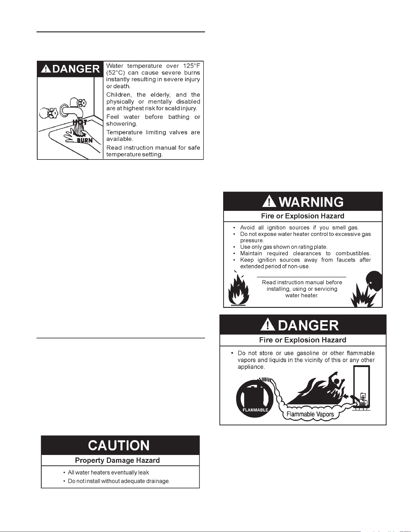
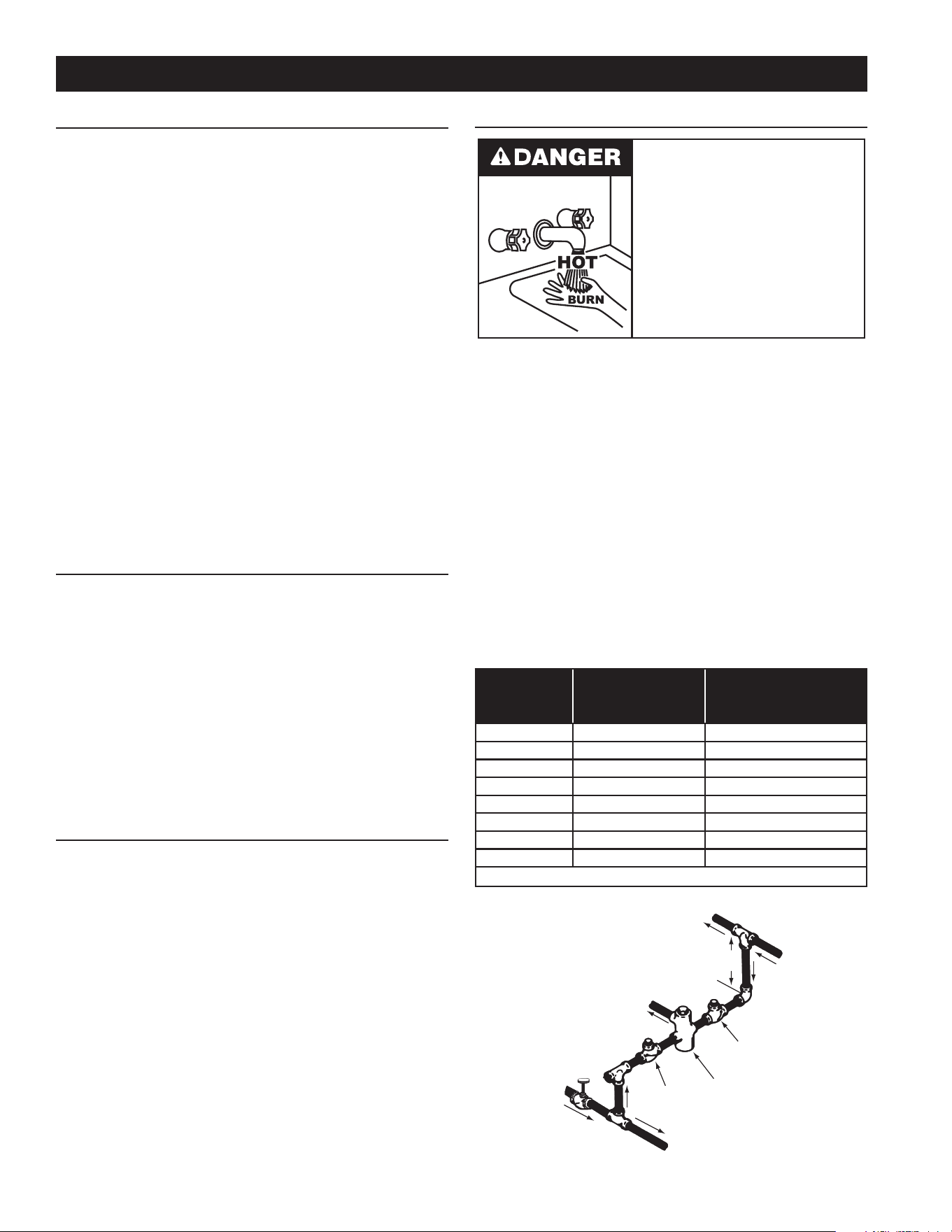
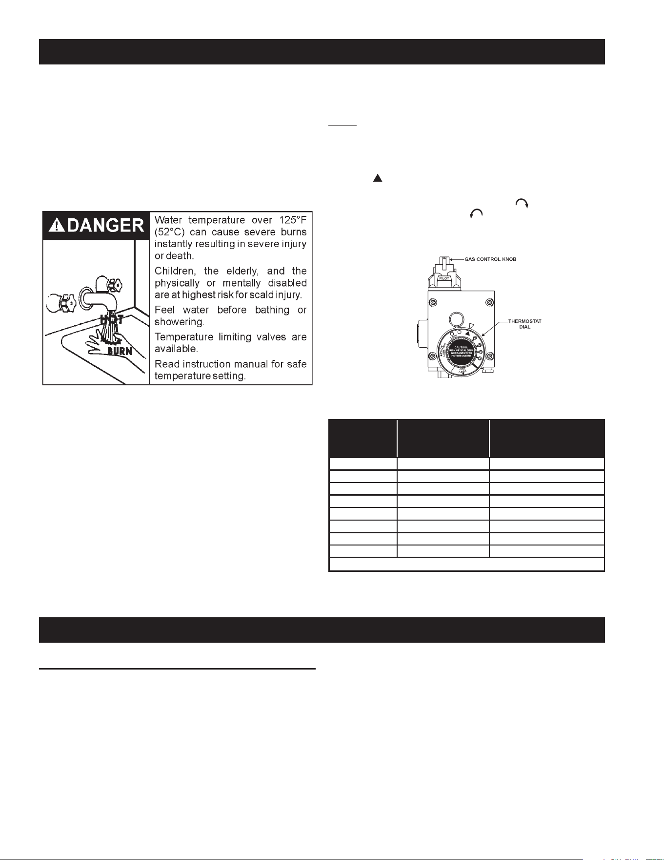
MIXING VALVES
Water temperature over 125°F (52°C)
can cause severe burns instantly
resulting in severe injury or death.
Children, the elderly and the physically
or mentally disabled are at highest risk
for scald injury.
Feel water before bathing or showering.
Temperature limiting devices such as
mixing valves must be installed when
required by codes and to ensure safe
temperatures at fixtures.
Waterheatedtoatemperaturewhichwillsatisfyclotheswashing,dish
washing,andothersanitizingneedscanscaldandcausepermanent
injuryuponcontact.Shortrepeatedheatingcyclescausedbysmall
hotwaterusescancausetemperaturesatthepointofusetoexceed
thewaterheater’stemperaturesettingbyupto20°F(11°C).
Somepeoplearemorelikelytobepermanentlyinjuredbyhotwater
than others. These include the elderly, children, the inrm and the
physically/mentally disabled. Table 2 shows the approximate time-
to-burnrelationshipfornormaladultskin.Ifanyoneusinghotwater
provided by the water heater being installed ts into one of these
groupsorifthereisalocalcodeorstatelawrequiringacertainwater
temperatureatthepointofuse,thenspecialprecautionsmustbetaken.
In addition to using the lowest possible temperature setting that
satisesdemandoftheapplicationaMixingValveshouldbeinstalled
atthewaterheaterorathotwatertapstofurtherreducesystemwater
temperature.SeeFigure6.
Mixing valves are available at plumbing supply stores. Consult
a Qualified Installer or ServiceAgency. Follow mixing valve
manufacturer’sinstructionsforinstallationofthevalves.
TABLE 2.
Water
Temperature°F
Timefor
1stDegreeBurn
(LessSevereBurns)
TimeforPermanentBurns
2nd&3rdDegree
(MostSevereBurns)
110
(normalshowertemp.)
116 (painthreshold)
116 35minutes 45minutes
122 1minute 5minutes
131 5seconds 25seconds
140 2seconds 5seconds
149 1second 2seconds
154 instantaneous 1second
(U.S.GovernmentMemorandum,C.P.S.C.,PeterL.Armstrong,Sept.15,1978)
HOT WATER
OUTLET
TO TANK
INLET
CHECK
VALVE
MIXING
VALVE
COLD
WATER
INLET
TEMPERED WATER
OUTLET
12” TO 15”
(30-38 cm)
CHECK
VALVE
FIGURE 6.
INSTALLATION REQUIREMENTS
11
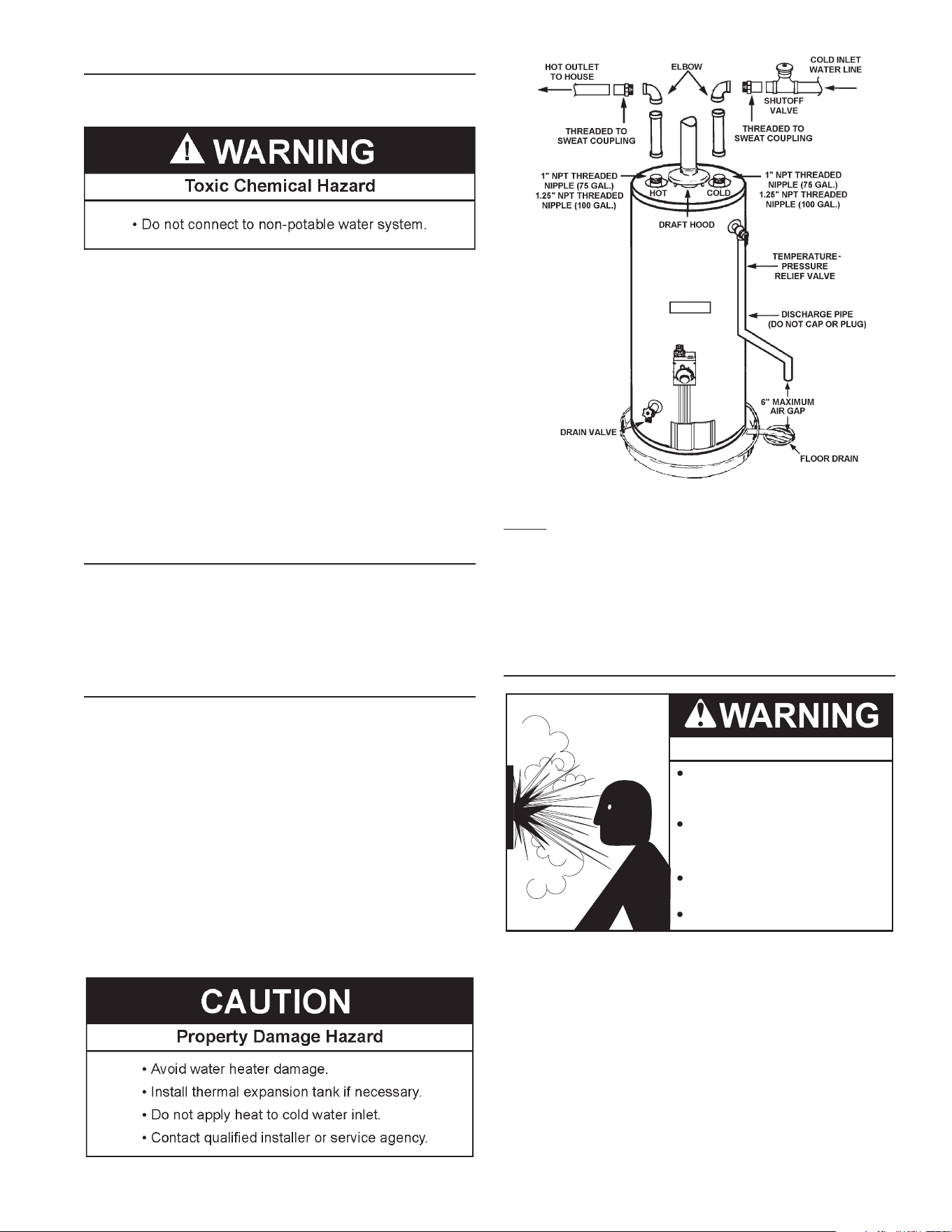
WATER PIPING
WATER (POTABLE) HEATING AND SPACE HEATING
Thiswaterheatershallnotbeconnectedtoanyheatingsystems
orcomponent(s)usedwithanon-potablewaterheatingappliance.
Allpipingcomponentsconnectedtothisunitforspaceheating
applicationsshallbesuitableforusewithpotablewater.
Toxicchemicals,suchasthoseusedforboilertreatmentshallnot
beintroducedintothissystem.
Whenthesystemrequireswaterforspaceheatingattemperatures
higherthanrequiredfordomesticwaterpurposes,amixingvalve
mustbeinstalled.PleaserefertoFigure2forsuggestedpiping
arrangement.
Thesewaterheaterscannotbeusedinspaceheatingapplications
only.
CLOSED WATER SYSTEMS
Water supply systems may, because of code requirements or
such conditions as high line pressure, among others, have
installed devices such as pressure reducing valves, check
valves,andbackflowpreventers.Devicessuchasthesecause
thewatersystemtobeaclosedsystem.
THERMAL EXPANSION
Aswaterisheated,itexpands(thermalexpansion).Inaclosed
systemthevolumeofwaterwillgrowwhenitisheated.Asthe
volumeofwatergrowstherewillbeacorrespondingincreasein
water pressure due to thermal expansion. Thermal expansion
cancauseprematuretankfailure(leakage).Thistypeoffailure
is not covered under the limited warranty. Thermal expansion
canalsocauseintermittentTemperature-PressureReliefValve
operation: water discharged from the valve due to excessive
pressurebuildup.Thisconditionisnotcoveredunderthelimited
warranty.TheTemperature-PressureReliefValveisnotintended
fortheconstantreliefofthermalexpansion.
A properly sized thermal expansion tank must be installed on
all closed systems to control the harmful effects of thermal
expansion.Contactalocalplumbingservicetechniciantohave
athermalexpansiontankinstalled.
FIGURE 7.
NOTE: To protect against untimely corrosion of hot and cold
waterttings,itisstronglyrecommendedthatdi-electricunions
orcouplingsbeinstalledonthiswaterheaterwhenconnectedto
copperpipe.
Figure7showsthetypicalattachmentofthewaterpipingtothe
waterheater.Thewaterheaterisequippedwith1”NPTthreaded
nipple (75 gallon models) or 1.25” NPT threaded nipple (100
gallonmodels)waterconnections.
TEMPERATURE-PRESSURE RELIEF VALVE
Explosion Hazard
Temperature-Pressure Relief Valve
must comply with ANSI Z21.22-
CSA 4.4 and ASME code.
Properly sized temperature-
pressure relief valve must be
installed in opening provided.
Can result in overheating and
excessive tank pressure.
Can cause serious injury or death.
This water heater is provided with a properly rated/sized and
certied combination Temperature-Pressure Relief Valve (T&P
valve)bythemanufacturer.Thevalveiscertiedbyanationally
recognizedtestinglaboratorythatmaintainsperiodicinspection
of production of listed equipment of materials as meeting the
requirements for Relief Valves for Hot WaterSupply Systems,
ANSIZ21.22•CSA4.4,andthecoderequirementsofASME.
Ifreplaced, the newT&Pvalvemustmeet therequirements of
localcodes,butnotlessthanacombinationTemperature-Pressure
ReliefValverated/sized andcertiedas indicatedin theabove
paragraph.Thenewvalvemustbemarkedwithamaximumset
pressurenottoexceedthemarkedhydrostaticworkingpressure
ofthewaterheater(150psi=1,035kPa)andadischargecapacity
notlessthanthewaterheaterBtu/hrorkWinputrateasshown
onthewaterheater’smodelratinglabel.
12
NOTE: Inadditionto the factoryinstalled Temperature-Pressure
ReliefValve onthewater heater, eachremotestorage tankthat
maybeinstalledandpipedtoawaterheatingappliancemustalso
have its own properly sized, rated and approved Temperature-
PressureReliefValveinstalled.Callthetollfreetechnicalsupport
phonenumberlistedonthebackcoverofthismanualfortechnical
assistanceinsizingaTemperature-PressureReliefValveforremote
storagetanks.
Forsafe operationofthewaterheater,theTemperature-Pressure
ReliefValvemustnotberemovedfromitsdesignatedopeningnor
plugged.TheTemperature-PressureReliefValvemustbeinstalled
directlyintothettingofthewaterheaterdesignedforthereliefvalve.
Installdischargepipingsothatanydischargewillexitthepipewithin
6inches(15.2cm)aboveanadequateoordrain,orexternaltothe
building.Incoldclimatesitisrecommendedthatitbeterminatedat
anadequatedraininsidethebuilding.Becertainthatnocontactis
madewithanyliveelectricalpart.Thedischargeopeningmustnot
beblockedorreducedinsizeunderanycircumstances.Excessive
length,over30feet(9.14m),oruseofmorethanfourelbowscan
causerestrictionandreducethedischargecapacityofthevalve.
No valve or other obstruction is to be placed between the
Temperature-PressureReliefValveandthetank.Donotconnect
dischargepipingdirectlytothedrainunlessa6”(15.2cm)airgapis
provided.Topreventbodilyinjury,hazardtolife,orpropertydamage,
therelief valve must beallowed to discharge waterin adequate
quantitiesshouldcircumstancesdemand.Ifthedischargepipeis
notconnectedtoadrainorothersuitablemeans,thewaterow
maycausepropertydamage.
Water Damage Hazard
•
Temperature-Pressure Relief Valve discharge
pipe must terminate at adequate drain.
CAUTION
T&P Valve Discharge Pipe Requirements:
• Shallnotbesmallerinsizethantheoutletpipesizeofthevalve,
orhaveanyreducingcouplingsorotherrestrictions.
• Shallnotbepluggedorblocked.
• Shallnotbeexposedtofreezingtemperatures.
• Shallbeofmateriallistedforhotwaterdistribution.
• Shallbeinstalledsoastoallowcompletedrainageofboththe
Temperature-PressureReliefValveandthedischargepipe.
• Mustterminateamaximumofsixinchesaboveaoordrain
orexternaltobuilding.Incoldclimates,itisrecommended
thatdischargepipebeterminatedatanadequatedraininside
building.
• Shallnothaveanyvalveorotherobstructionbetweenthe
reliefvalveandthedrain.
Burn hazard.
Hot water discharge.
Keep clear of Temperature-
Pressure Relief Valve
discharge outlet.
TheTemperature-PressureReliefValvemustbemanuallyoperated
atleasttwiceayear.Cautionshouldbetakentoensurethat(1)no
oneisinfrontoforaroundtheoutletoftheTemperature-Pressure
ReliefValvedischargeline,and(2)thewatermanuallydischarged
will not cause any bodily injury or property damage because
thewater maybe extremelyhot. Ifafter manuallyoperating the
valve,itfailstocompletelyresetandcontinuestoreleasewater,
immediatelyclosethecoldwaterinlettothewaterheater,followthe
draininginstructionsinthismanual,andreplacetheTemperature-
PressureReliefValvewithaproperlyrated/sizednewone.
NOTE:ThepurposeofaTemperature-PressureReliefValveisto
preventexcessivetemperaturesandpressuresinthestoragetank.
The T&P valve is not intended for the constant relief of thermal
expansion.Aproperlysizedthermalexpansiontankmustbeinstalled
on all closed systems to control thermal expansion, see Closed
WaterSystemsandThermalExpansiononpage11.
If you do not understand these instructions or have any questions
regardingtheTemperature-PressureReliefValvecallthetollfreenumber
listedonthebackcoverofthismanualfortechnicalassistance.
FILLING THE WATER HEATER
Neverusethiswater heaterunlessitis completelyfullofwater.To
preventdamagetothetank,thetankmustbelledwithwater.Water
mustowfrom thehotwater faucetbeforeturning “ON”gastothe
waterheater.
Tollthewaterheaterwithwater:
1.Close the water heater drain valve by turning the handle to the
right(clockwise).Thedrainvalveisonthelowerfrontofthewater
heater.
2. Open the cold water supply valve to the water heater.
NOTE:Thecoldwatersupplyvalvemustbeleftopenwhenthe
waterheaterisinuse.
3.Toinsurecompletellingofthetank,allowairtoexitbyopeningthe
nearesthotwaterfaucet.Allowwatertorununtilaconstantowis
obtained.Thiswillletairoutofthewaterheaterandthepiping.
4. Checkallwaterpiping andconnectionsforleaks.Repair as
needed.
AIR REQUIREMENTS
Breathing Hazard - Carbon Monoxide Gas
Install water heater in accordance with
the Instruction Manual and NFPA 54 or
CAN/CSA-B149.1.
To avoid injury, combustion and ventilation
air must be taken from outdoors.
Do not place chemical vapor emitting
products near water heater.
Breathing carbon monoxide can cause brain damage or
death. Always read and understand instruction manual.
For safe operation an adequate supply of fresh uncontaminated air for
combustionandventilationmustbeprovided.
An insufcient supply of air can cause recirculation of combustion
products resulting in contamination that may be hazardous to life.
Suchaconditionoftenwillresultinayellow,luminousburnerame,
causingsootingofthecombustionchamber,burnersanduetubes
andcreatesariskofasphyxiation.
Donotinstallthewaterheaterinaconnedspaceunlessanadequate
supplyofairforcombustionandventilationisbroughtintothatspace
usingthemethodsdescribedintheConnedSpacesectionthatfollows.
Neverobstructtheowofventilationair.Ifyouhaveanydoubtsor
questionsatall,callyour gassupplier.Failure toprovidetheproper
13
amountofcombustionaircanresultinareorexplosionandcauseproperty
damage,seriousbodilyinjuryordeath.
UNCONFINED SPACE
AnUnconfinedSpaceisonewhosevolumeisnotlessthan50
cubic feet per 1,000 Btu/hr (4.8 cubic meters per kW) of the
totalinputratingofallappliancesinstalledinthespace.Rooms
communicatingdirectlywiththespace, inwhichtheappliances
are installed, through openings not furnished with doors, are
consideredapartoftheunconfinedspace.
Makeupairrequirementsfortheoperationofexhaustfans,kitchen
ventilationsystems, clothesdryersand fireplacesshall also be
considered in determining the adequacy of a space to provide
combustion,ventilationanddilutionair.
UNUSUALLY TIGHT CONSTRUCTION
Inunconfinedspacesinbuildings,infiltrationmaybeadequateto
provideairforcombustion,ventilationanddilutionoffluegases.
However,inbuildingsofunusuallytightconstruction(forexample,
weatherstripping,heavilyinsulated,caulked,vaporbarrier,etc.)
additionalairmustbeprovidedusingthemethodsdescribedin
theConfinedSpacesectionthatfollows.
CONFINED SPACE
AConnedSpaceisonewhosevolumeislessthan50cubicfeetper
1,000Btu/hr(4.8cubicmetersperkW)ofthetotalinputratingofall
appliancesinstalledinthespace.
Openingsmustbeinstalledtoprovidefreshairforcombustion,ventilation
and dilution in conned spaces. The required size for the openings is
dependentonthemethodusedtoprovidefreshairtotheconnedspace
andthetotalBtu/hrinputratingofallappliancesinstalledinthespace.
DIRECT VENT APPLIANCES
Appliances installed in a Direct Vent conguration that derive all
air for combustion from the outdoor atmosphere through sealed
intakeairpipingarenotfactoredinthetotalapplianceinputBtu/hr
calculationsusedtodeterminethesizeofopeningsprovidingfresh
airintoconnedspaces.
EXHAUST FANS
Whereexhaustfansareinstalled,additionalairshallbeprovided
toreplacetheexhaustedair.Whenanexhaustfanisinstalledin
thesamespacewithawaterheater,sufficientopeningstoprovide
freshairmustbeprovidedthataccommodatetherequirements
forallappliancesintheroomandtheexhaustfan.Undersized
openingswillcauseairtobedrawnintotheroomthroughthewater
heater’sventsystemcausingpoorcombustion.Sooting,serious
damagetothewaterheaterandtheriskoffireorexplosionmay
result.Itcanalsocreateariskofasphyxiation.
LOUVERS AND GRILLES
Thefreeareasofthefreshairopeningsintheinstructionsthatfollowdonot
takeintoaccountthepresenceoflouvers,grillesorscreensintheopenings.
Therequiredsizeofopeningsforcombustion,ventilationanddilution
airshallbebasedonthe“netfreearea”ofeachopening.Wherethe
freeareathroughadesignoflouverorgrilleorscreenisknown,itshall
beusedincalculatingthesizeofopeningrequiredtoprovidethefree
areaspecied.Wherethelouverandgrilledesignandfreeareaarenot
known,itshallbeassumedthatwoodlouverswillhave25%freearea
andmetallouversandgrilleswillhave75%freearea.Nonmotorized
louversandgrillesshallbexedintheopenposition.
FRESH AIR OPENINGS FOR CONFINED SPACES
The following instructions shall be used to calculate the size,
number and placement of openings providing fresh air for
combustion, ventilation and dilution in confined spaces. The
illustrationsshowninthissectionofthemanualareareferencefor
theopeningsthatprovidefreshairintoconfinedspacesonly.Do
notrefertotheseillustrationsforthepurposeofventinstallation.
SeeVentingonpage14forcompleteventinginstructions.
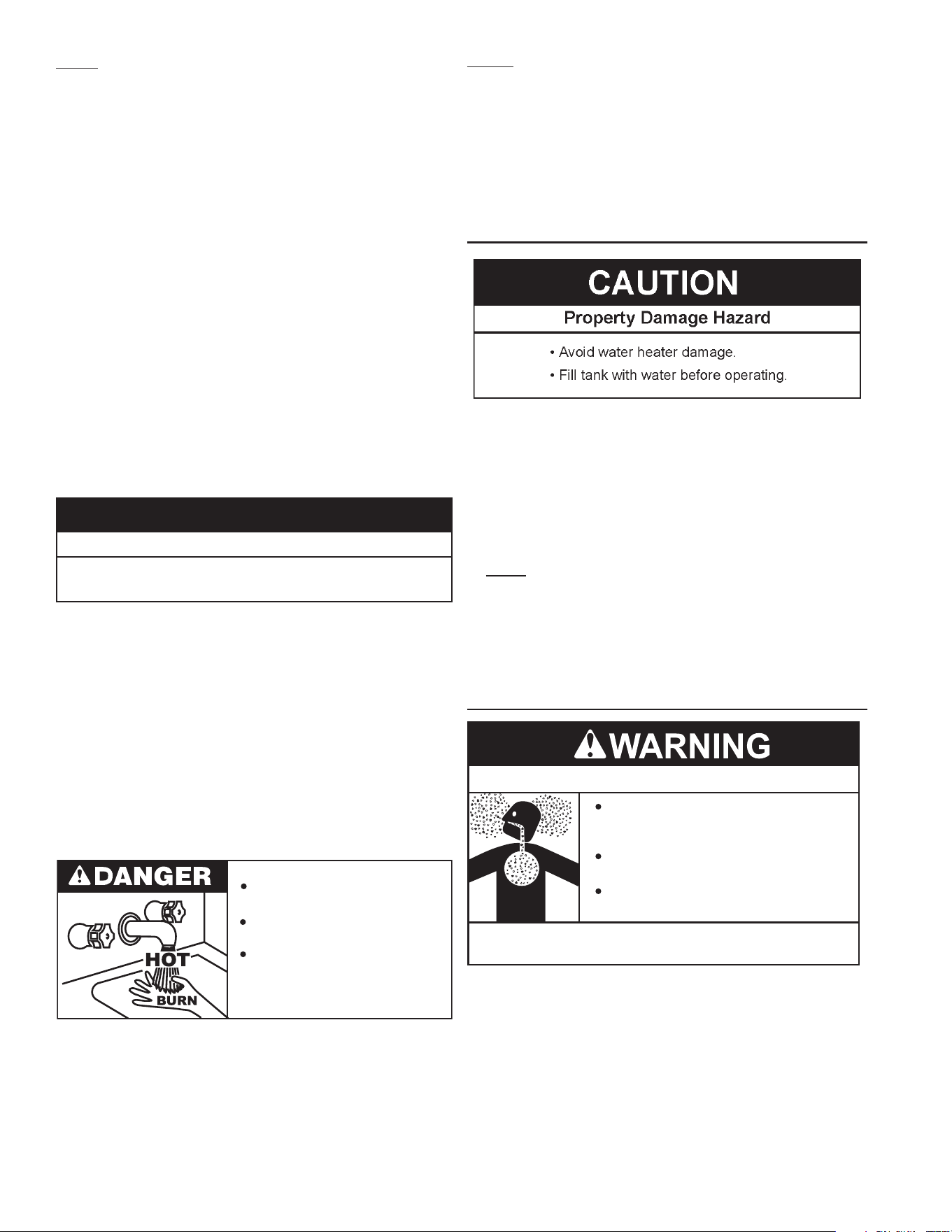
OUTDOOR AIR THROUGH TWO OPENINGS
FIGURE 8.
The confined space shall be provided with two permanent
openings,onecommencingwithin12inches(300mm)ofthetop
andonecommencingwithin12inches(300mm)ofthebottomof
the enclosure. The openings shall communicate directly with the
outdoors.SeeFigure8.
Eachopeningshallhaveaminimumfreeareaof1squareinchper
4,000Btu/hr(550mm2perkW)oftheaggregateinputratingofall
appliancesinstalledintheenclosure.Eachopeningshallnotbeless
than100squareinches(645cm2).
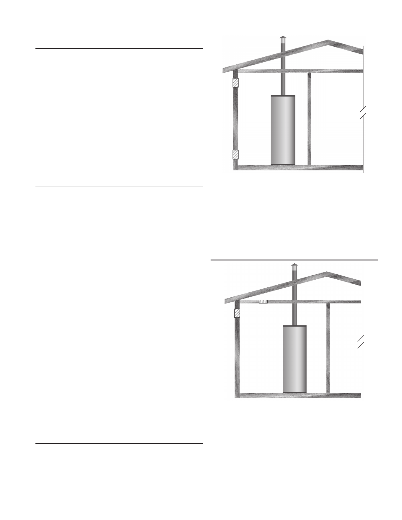
OUTDOOR AIR THROUGH ONE OPENING
FIGURE 9.
Alternatively a single permanent opening, commencing within 12
inches(300mm)ofthetopoftheenclosure,shallbeprovided.See
Figure9.Thewaterheatershallhaveclearancesofatleast1inch
(25mm)fromthesidesandbackand6inches(150mm)fromthe
frontoftheappliance.Theopeningshalldirectlycommunicatewith
theoutdoorsorshallcommunicatethroughaverticalorhorizontalduct
totheoutdoorsorspacesthatfreelycommunicatewiththeoutdoors
andshallhaveaminimumfreeareaofthefollowing:
1. 1 square inch per3000Btu/hr(733 mm
2
per kW)ofthe total
inputratingofallapplianceslocatedintheenclosure,and
2. Notlessthanthesumoftheareasofallventconnectorsin
thespace.
14
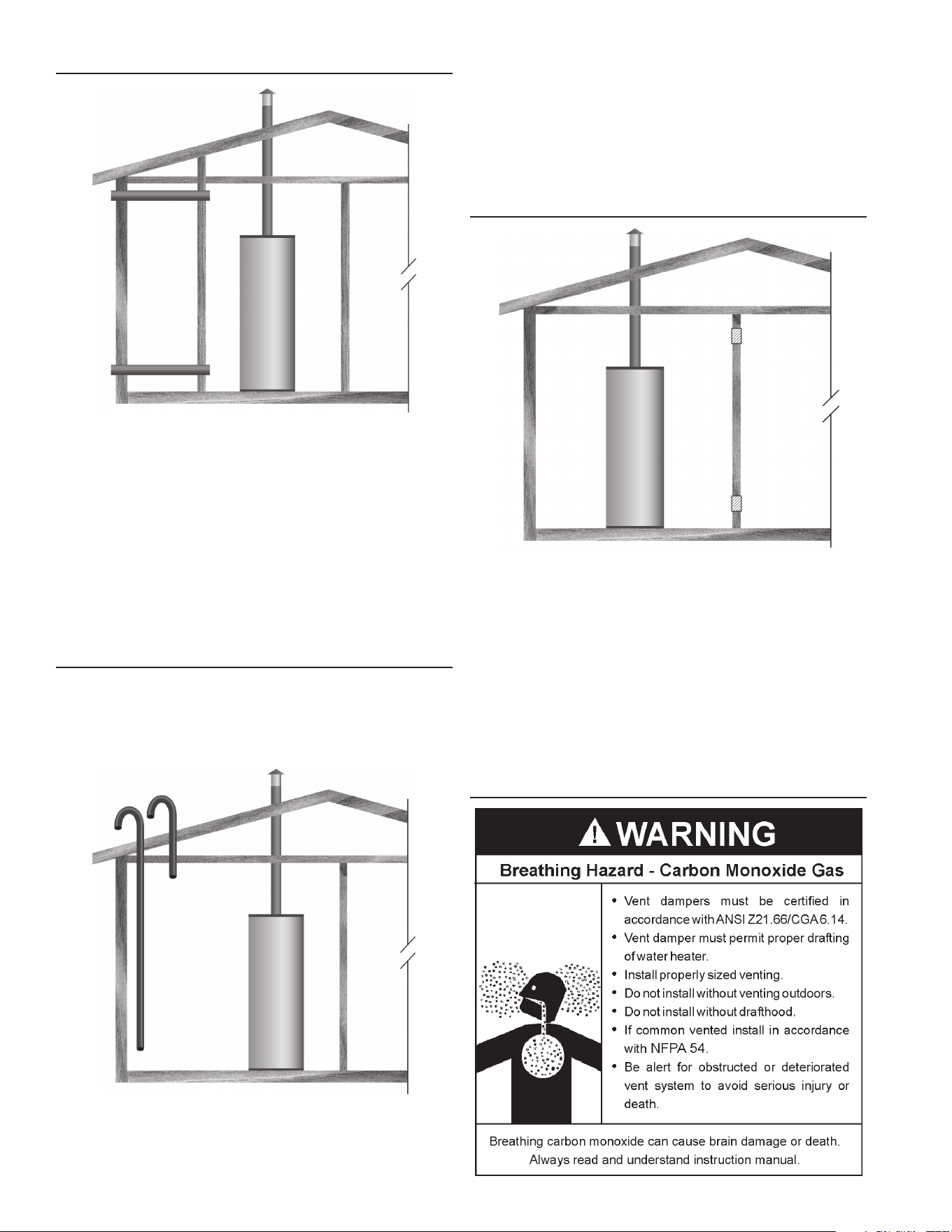
OUTDOOR AIR THROUGH TWO HORIZONTAL DUCTS
FIGURE 10.
Theconnedspaceshallbeprovidedwithtwopermanenthorizontal
ducts,onecommencingwithin12inches(300mm)ofthetopand
onecommencingwithin12inches(300mm)ofthebottomofthe
enclosure.The horizontal ducts shall communicate directlywith
theoutdoors.SeeFigure10.
Eachductopeningshallhaveaminimumfreearea of1square
inchper2,000Btu/hr(1100mm2perkW)oftheaggregateinput
ratingofallappliancesinstalledintheenclosure.
Whenductsareused,theyshallbeofthesamecrosssectional
areaasthefreeareaoftheopeningstowhichtheyconnect.The
minimumdimensionofrectangularairductsshallbenotlessthan
3inches.
OUTDOOR AIR THROUGH TWO VERTICAL DUCTS
The illustrations shown in this section of the manual are a
reference for the openings that provide fresh air into conned
spacesonly.
DO NOT refer to these illustrations for the purpose of vent
installation.SeeVentingforcompleteventinginstructions.
FIGURE 11.
Theconned space shall be provided with twopermanentvertical
ducts,onecommencing within12 inches(300mm) ofthe topand
one commencing within 12 inches (300 mm) of the bottom of the
enclosure. The vertical ducts shall communicate directly with the
outdoors.SeeFigure11.
Eachductopeningshallhaveaminimumfreeareaof1squareinch
per4,000Btu/hr(550mm2perkW)oftheaggregateinputratingof
allappliancesinstalledintheenclosure.
Whenductsareused,theyshallbeofthesamecrosssectionalarea
asthefreeareaoftheopeningstowhichtheyconnect.Theminimum
dimensionofrectangularairductsshallbenotlessthan3inches.
AIR FROM OTHER INDOOR SPACES
FIGURE 12.
Theconnedspaceshallbeprovidedwithtwopermanentopenings,
one commencing within 12 inches (300 mm) of the top and one
commencingwithin12inches(300mm)ofthebottomoftheenclosure.
SeeFigure12.
Eachopeningshallcommunicatedirectlywithanadditionalroom(s)
ofsufcientvolumesothatthecombinedvolumeofallspacesmeets
thecriteriaforanUnconnedSpace.
Eachopeningshallhaveaminimumfreeareaof1squareinchper
1,000Btu/hr(2200mm2perkW)oftheaggregateinputratingofall
appliancesinstalledintheenclosure.Eachopeningshallnotbeless
than100squareinches(645cm2).
VENTING
15
Ifthewaterheaterisbeinginstalledasareplacementforanexisting
heaterinpre-existingventing,athoroughinspectionofexistingventing
systemmustbeperformedpriortoanyinstallationwork.
VENTDAMPERS-Anyventdamper,whetheritisoperatedthermally
orotherwisemustberemovedifitsuseinhibitsproperdraftingofthe
waterheater.
ThermallyOperatedVentDampers:thisgas-redwaterheaterhas
athermalefciencyatorabove80%whichmayproducearelatively
lowuegastemperature.Suchtemperaturesmaynotbehighenough
toproperlyopenthermallyoperatedventdampers.Thiswouldcause
spillageoftheuegasesandmaycausecarbonmonoxidepoisoning.
Ventdampersmustbearevidenceofcerticationascomplyingwith
thecurrenteditionoftheAmericanNationalStandardANSIZ21.66
CGA 6.14 (covering electrically and mechanically actuated vent
dampers).Beforeinstallationofanyventdamper,consultthelocal
gasutilityforfurtherinformation.
Toinsureproperventingofthisgas-redwaterheater,thecorrect
ventpipediametermustbeutilized.Anyadditionsordeletionsof
othergasappliancesonacommonventwiththiswaterheatermay
adverselyaffecttheoperationofthewaterheater.Consultyourgas
supplierifanysuchchangesareplanned.
Forproper venting in certain installations, alargerdiameter vent
pipe may be necessary. Consult your gas supplier to aid you in
determiningtheproperventingforyourwaterheaterfromthevent
tablesinthe currenteditionoftheNationalFuelGasCodeANSI
Z223.1/NFPA54ortheNaturalGasandPropaneInstallationCode
CAN\CSA B 149.1.
Periodically check the venting system for signs of obstruction or
deteriorationandreplaceifneeded.
Thecombustionandventilationairowmustnotbeobstructed.
Thewaterheaterwithdrafthoodinstalledmustbeconnectedtoa
chimneyorlistedventpipesystem,whichterminatestotheoutdoors.
Neveroperatethewaterheaterunlessitisventedtotheoutdoors
and has adequate air supply to avoid risks ofimproper operation,
explosionorasphyxiation.
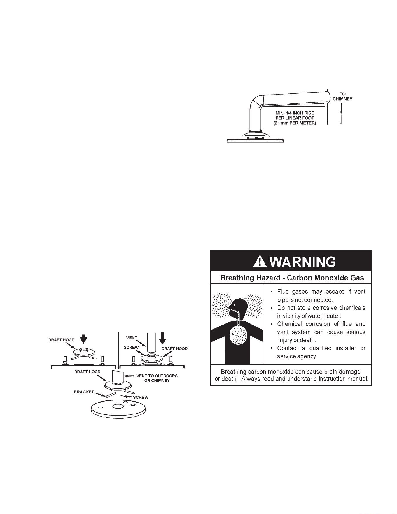
• For proper draft hood attachment, the draft hood legs may be
angledslightlyinward.
• Placethedrafthoodlegsinthereceivingholesonthetopofthe
water heater. The legs will snap in theholes togive atight t.
Securedrafthoodwiththesuppliedbrackets.
• Placetheventpipeoverthedrafthood.Withtheventpipeinposition,
drillasmallholethroughboththeventpipeanddrafthood.Secure
themtogetherwithasheetmetalscrew.SeeFigure13.
Obstructedordeterioratedventsystemsmaypresentserioushealth
riskorasphyxiation.
FIGURE 13.
The vent pipe from the water heater must be no less than the
diameter of the draft hood outlet on the water heater and must
slopeupwardatleast1/4inchperlinearfoot(21mmpermeter).
SeeFigure14.
Allvent gases must becompletelyvented to the outdoorsof the
structure(dwelling). Installonlythedrafthoodprovided withthe
newwaterheaterandnootherdrafthood.
Ventpipesmustbesecuredateachjointwithsheetmetalscrews.
FIGURE 14.
Theremustbeaminimumof6”(153mm)clearancebetweensingle
wall vent pipe and any combustible material. Fill and seal any
clearancebetweensinglewallventpipeandcombustiblematerial
withmortarmix,cement,orothernoncombustiblesubstance.For
other than single wall, follow vent pipe manufacturer’sclearance
specications.Toinsureatighttoftheventpipeinabrickchimney,
sealaroundtheventpipewithmortarmixcement.
Failure to have required clearances between vent piping and
combustiblematerialwillresultinarehazard.
Be sure vent pipe is properly connected to prevent escape of
dangerousuegaseswhichcouldcausedeadlyasphyxiation.
Chemicalvaporcorrosionoftheflueandventsystemmayoccur
ifairforcombustioncontainscertainchemicalvapors.Spraycan
propellants,cleaningsolvents,refrigeratorandair conditioner
refrigerants,swimming poolchemicals, calcium and sodium
chloride,waxes, bleach and process chemicals are typical
compoundswhicharepotentiallycorrosive.
16
GAS PIPING
Contact your local gas service company to ensure that adequate
gasserviceisavailableandtoreviewapplicableinstallationcodes
foryourarea.
SizethemaingaslineinaccordancewithTable3.Theguresshown
areforstraightlengthsofpipeat0.5in.W.C.pressuredrop,whichis
considerednormalforlowpressuresystems.Note:Fittingssuchas
elbows,teesandlineregulatorswilladdtothepipepressuredrop.
AlsorefertothecurrenteditionsoftheNationalFuelGasCode(NFPA
54)orNaturalGasandPropaneInstallationCode(CAN/CSAB149.1).
Makesuregassuppliedissametypelistedonmodelratingplate.The
inletgaspressuremustnotexceed14inchwatercolumn(2.6kPa)
fornaturalandpropane(L.P.)gas.Theminimuminletgaspressure
shownonratingplateisthatwhichwillpermitringatratedinput.
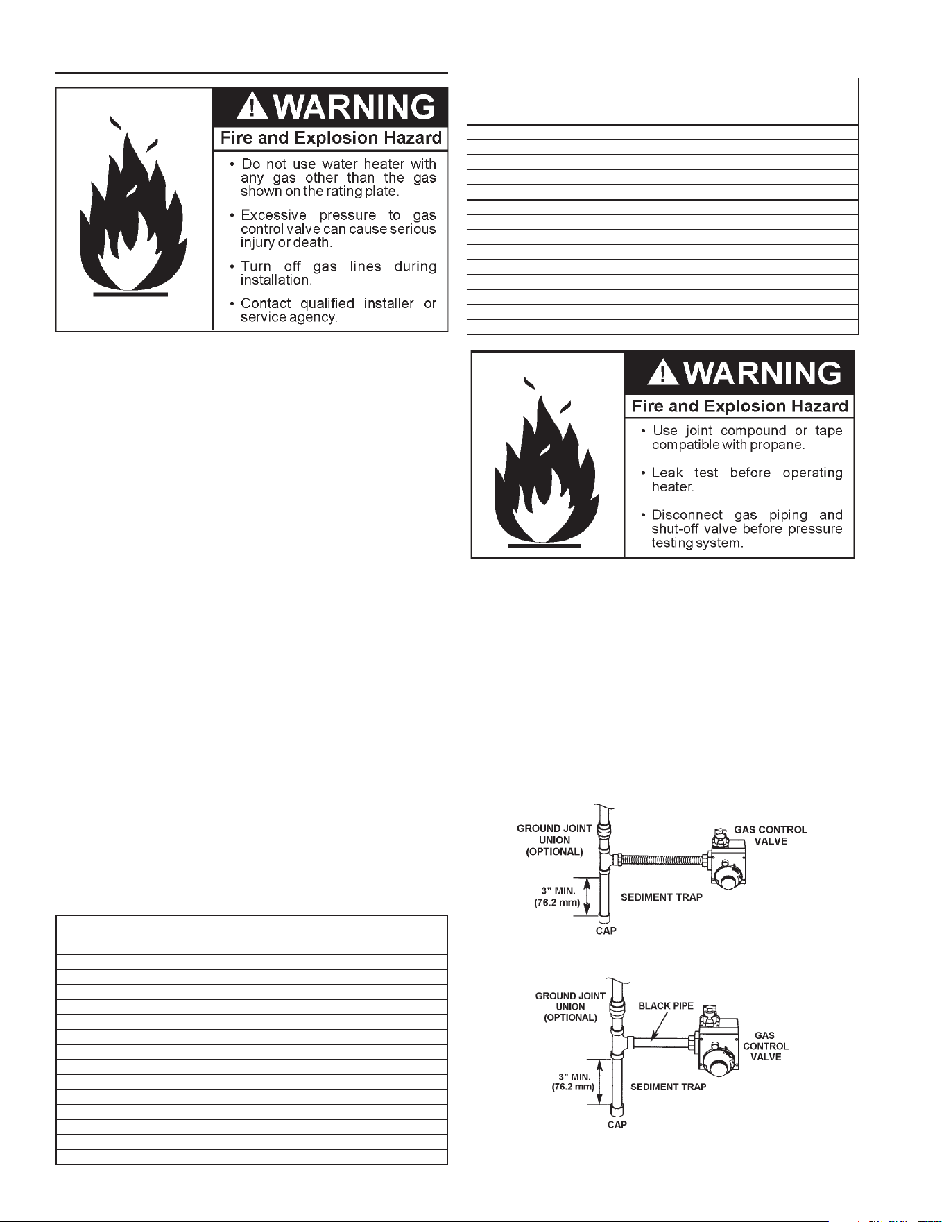
Ifthegascontrolvalveissubjectedtopressuresexceeding1/2pound
persquareinch(3.5kPa),thedamagetothegascontrolvalvecould
resultinareorexplosionfromleakinggas.
Ifthemaingaslineshut-offservingallgasappliancesisused,also
turn“off”thegasateachappliance.Leaveallgasappliancesshut
“off”untilthewaterheaterinstallationiscomplete.
Agaslineofsufcientsizemustberuntothewaterheater.Consult
thecurrenteditionofNationalFuelGasCodeANSIZ223.1/NFPA54
ortheNaturalGasandPropaneInstallationCodeCAN/CSAB149.1
andyourgassupplierconcerningpipesize.
Theremustbe:
• Areadily accessiblemanualshut offvalvein thegassupply line
servingthewaterheater,and
• Asedimenttrapaheadofthegascontrolvalvetohelppreventdirt
andforeignmaterialsfromenteringthegascontrolvalve.
• Aexiblegasconnectororagroundjointunionbetweentheshut
offvalveandcontrolvalvetopermitservicingoftheunit.
Besuretocheckallthegaspipingforleaksbeforelightingthewater
heater.Useasoapywatersolution,notamatchoropename.Rinse
offsoapysolutionandwipedry.
The minimum inlet gas pressure shown on the rating plateis that
whichwillpermitringattheratedinput.
TABLE 3. GAS SUPPLY LINE SIZES (IN INCHES)*
MAXIMUM CAPACITY OF PIPE IN CUBIC FEET PER HOUR
LENGTH
IN
FEET
NOMINAL IRON PIPE SIZES (
INCHES
)
INPUT IN THOUSANDS (BTU/HR)
1/2" 3/4" 1" 1 1/4" 1 1/2" 2" 2 1/2" 3" 4"
10 175 360 680 1400 2100 3960 6300 11000 23000
20 120 250 465 950 1460 2750 4360 7700 15800
30 97 200 375 770 1180 2200 3520 6250 12800
40 82 170 320 660 990 1900 3000 5300 10900
50 73 151 285 580 900 1680 2650 4750 9700
60 66 138 260 530 810 1520 2400 4300 8800
70 61 125 240 490 750 1400 2250 3900 8100
80 57 118 220 460 690 1300 2050 3700 7500
90 53 110 205 430 650 1220 1950 3450 7200
100 50 103 195 400 620 1150 1850 3250 6700
125 44 93 175 360 550 1020 1650 2950 6000
150 40 84 160 325 500 950 1500 2650 5500
175 37 77 145 300 460 850 1370 2450 5000
200 35 72 135 280 430 800 1280 2280 4600
TABLE 4.
LENGTH
IN
METERS
NOMINAL IRON PIPE SIZES (
INCHES
)
INPUT IN KW
1/2" 3/4" 1" 1 1/4" 1 1/2" 2" 2 1/2" 3" 4"
3 51 105 199 410 615 1160 1845 3221 6735
6 35 73 142 278 428 805 1277 2255 4626
9 28 59 110 225 346 644 1031 1830 3748
12 24 50 94 193 290 556 878 1552 3192
15 21 44 83 170 264 492 776 1391 2840
18 19 40 76 155 237 445 703 1259 2577
21 18 37 70 143 220 410 659 1142 2372
24 17 35 64 135 202 381 600 1083 2196
27 16 32 60 126 190 357 571 1010 2108
31 15 30 57 117 182 337 542 952 1962
38 13 27 51 105 161 299 483 864 1757
46 12 25 47 95 146 278 439 776 1610
53 11 23 42 88 135 249 401 717 1464
61 10 21 40 82 126 234 375 688 1347
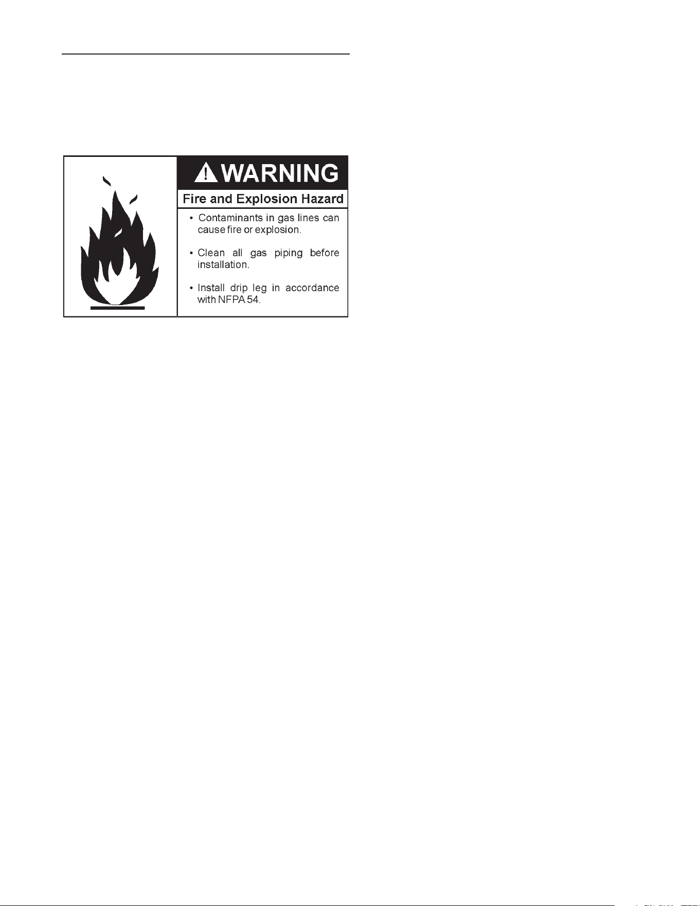
Usepipejointcompoundorteontapemarkedasbeingresistantto
theactionofpetroleum[Propane(L.P.)]gases.
Thewaterheateranditsgasconnectionmustbeleaktestedbefore
placingthewaterheaterinoperation.
The water heater and its individual shut-off valve shall be
disconnectedfromthegassupplypipingsystemduringanypressure
testingofthatsystemattestpressuresinexcessof1/2poundper
squareinch(3.5kPa).Itshallbeisolatedfromthegassupplypiping
system by closing its individual manual shut-off valve during any
pressuretestingof thegassupply pipingsystemat testpressures
equaltoorlessthan1/2poundpersquareinch(3.5kPa).
Connectingthegaspipingtothegascontrolvalveofthewaterheater
canbeaccomplishedbyeitherofthetwomethodsshowninFigures
15 and 16.
FIGURE 15. GAS PIPING WITH FLEXIBLE CONNECTOR.
FIGURE 16. GAS PIPING WITH ALL
BLACK IRON PIPE TO GAS CONTROL.
17
SEDIMENT TRAPS
Asedimenttrapshallbeinstalledasclosetotheinletofthewater
heateraspracticalatthetimeofwaterheaterinstallation.The
sedimenttrapshallbeeitherateefittingwithacappednipple
inthebottomoutletorotherdevicerecognizedasaneffective
sediment trap. If a tee fitting is used, it shall be installed in
conformance with one of themethods of installation shown in
theFigures15and16.
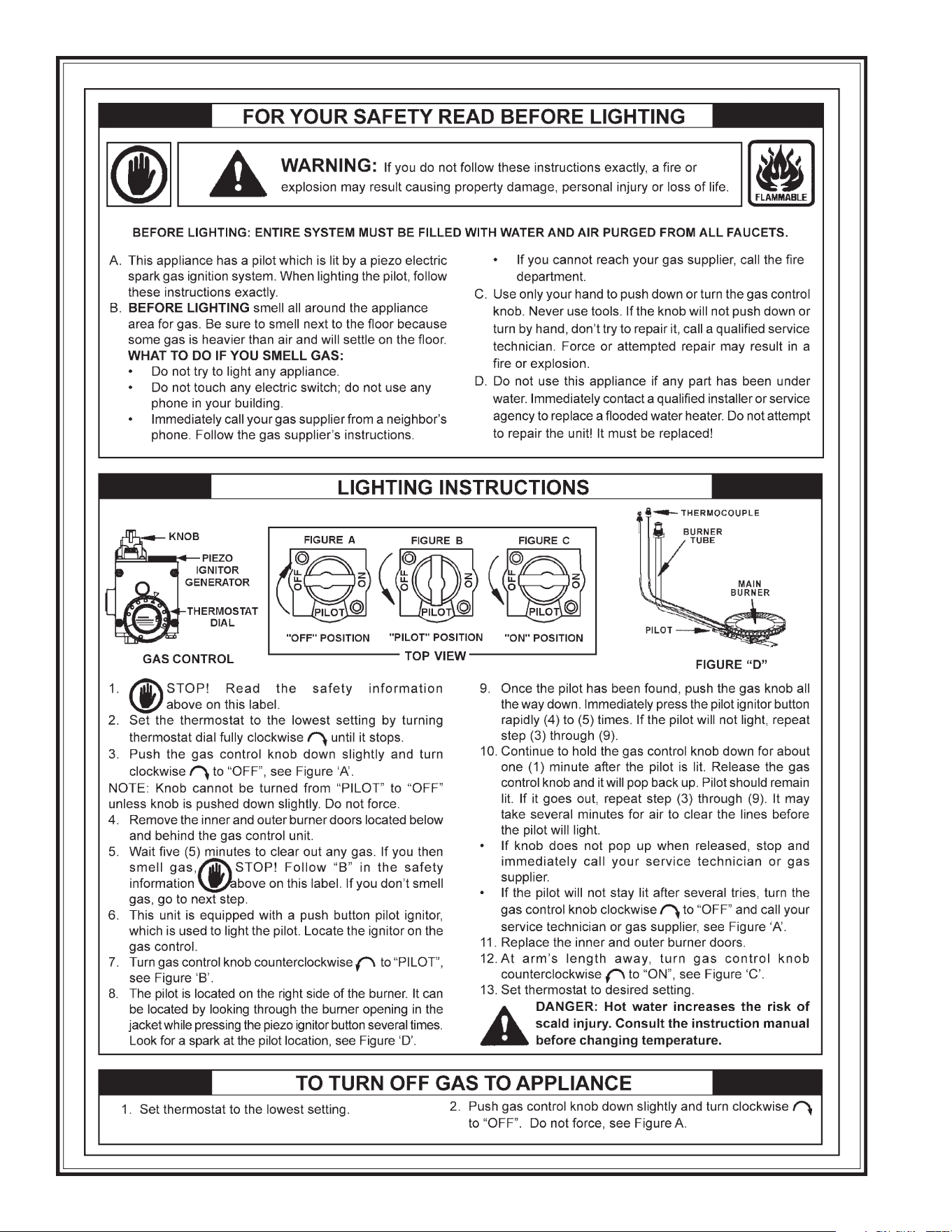
Contaminantsinthegaslinesmaycauseimproperoperationof
thegascontrolvalvethatmayresultinfireorexplosion.Before
attachingthegaslinebesurethatallgaspipeiscleanonthe
inside.Totrapanydirtorforeignmaterialinthegassupplyline,
asedimenttrapmustbeincorporatedinthepiping.Thesediment
trapmustbereadilyaccessible.Installinaccordancewiththe
“GasPiping”section.RefertothecurrenteditionoftheNational
FuelGasCode,ANSIZ223.1/NFPA54ortheNaturalGasand
PropaneInstallationCodeCAN/CSAB149.1.
18
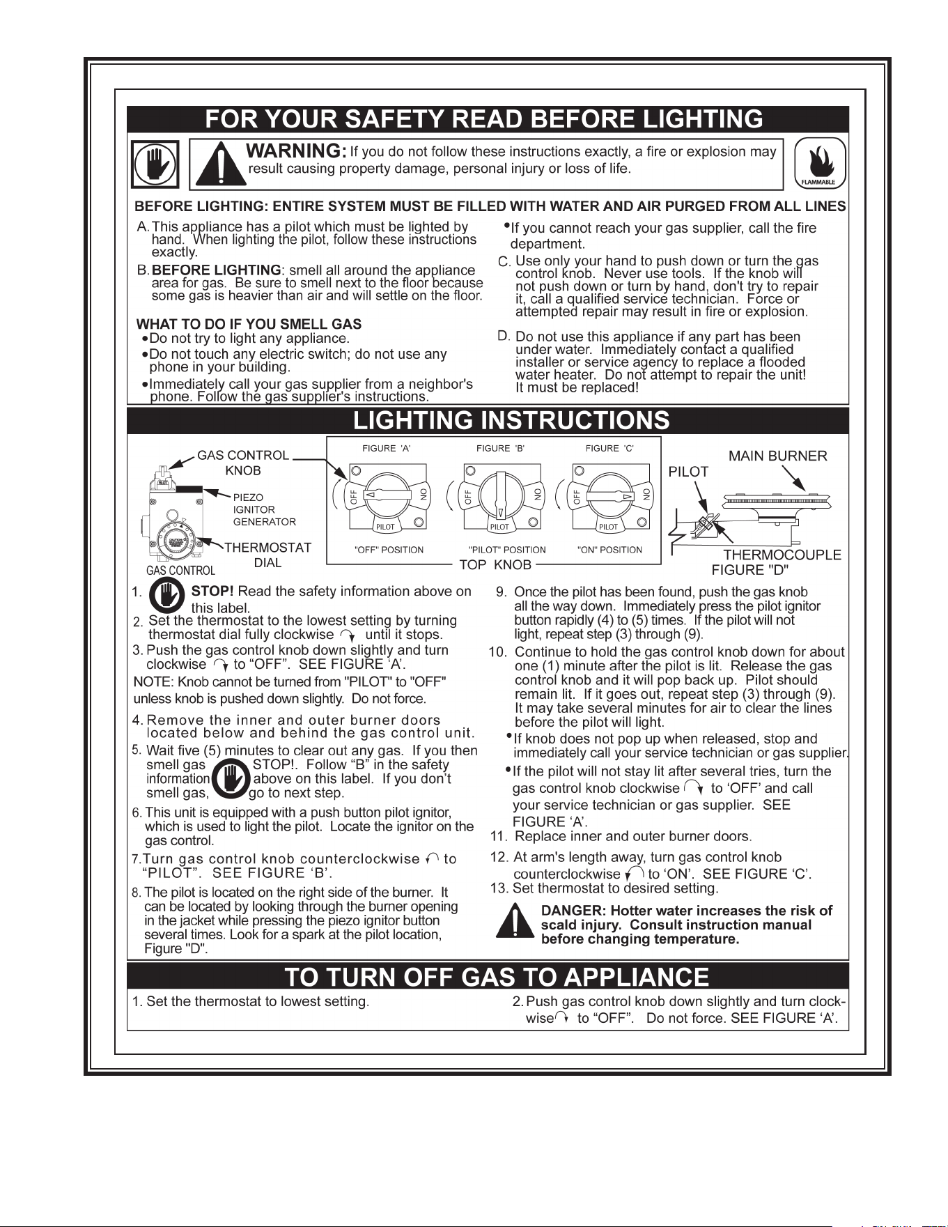
19
20
START UP CONDITIONS
DRAFT HOOD OPERATION
Check draft hood operation by performing a worst case
depressurization of the building. With all doors and windows
closed, and with all air handling equipment and exhaust fans
operating such as furnaces, clothes dryers, range hoods and
bathroomfans,amatchameshouldstillbedrawnintothedraft
hoodofthewaterheaterwithitsburnerring.Iftheameisnot
drawn toward the draft hood, shut off water heater and make
necessaryairsupplychangestocorrect.
CONDENSATION
Whenever the water heater is filled with cold water,some
condensatewillformwhiletheburnerison.Awaterheatermay
Shortrepeatedheatingcyclescausedbysmallhotwaterusescan
causetemperatures atthe pointof useto exceedthe thermostat
settingbyupto30°F(16.7°C).Ifyouexperiencethistypeofuse
you should consider using lower temperature settings to reduce
scaldhazards.
Anywaterheater’sintendedpurposeistoheatwater.Hotwater
isneededforcleansing,cleaning,andsanitizing(bodies,dishes,
clothing).Untempered hot water can present a scald hazard.
Dependingonthetimeelement,andthepeopleinvolved(adults,
children, elderly, inrm, etc.) scalding may occur at different
temperatures.
HOTTERWATERCANSCALD:Waterheatersareintendedtoproduce
hotwater.Waterheatedtoatemperaturewhichwillsatisfyspace
heating,clotheswashing,dishwashing,andothersanitizingneeds
canscaldandpermanentlyinjureyouuponcontact.Somepeople
aremorelikelytobepermanentlyinjuredbyhotwaterthanothers.
Theseincludetheelderly,children,theinrm,orphysically/mentally
handicapped.Ifanyoneusinghotwaterinyourhometsintooneof
thesegroupsorifthereisalocalcodeorstatelawrequiringacertain
temperaturewateratthehotwatertap,thenyoumusttakespecial
precautions. In addition to using the lowest possible temperature
settingthatsatisesyourhotwaterneeds,ameanssuchasamixing
valveshouldbeusedatthehotwatertapsusedbythesepeopleor
atthewaterheater.Mixingvalvesareavailableatplumbingsupplyor
hardwarestores,seeFigure2.Followmanufacturer’sinstructionsfor
installationofthevalves.Beforechangingthefactorysettingonthe
thermostat,readthe“TemperatureRegulation”sectioninthismanual,
seeFigures17and18.
TEMPERATURE REGULATION
FOR YOUR INFORMATION
appeartobeleakingwheninfactthewateriscondensation.This
usuallyhappenswhen:
a.Anewwaterheaterislledwithcoldwaterforthersttime.
b.Burninggasproduceswatervaporinwaterheaters,par ticular ly
highefciencymodelswhereuetemperaturesarelower.
c.Largeamountsofhotwaterareusedinashorttimeandthe
rellwaterinthetankisverycold.
Moisturefromtheproductsofcombustioncondenseonthecooler
tanksurfaces and form drops of waterwhichmay fall onto the
burnerorotherhotsurfacestoproducea“sizzling”or“frying”noise.
Excessive condensation can cause pilot outage due to water
runningdownthefluetubeontothemainburnerandputtingout
thepilot.
Neverallowsmallchildrentouseahotwatertap,ortodrawtheirown
bathwater.Neverleaveachildorhandicappedpersonunattended
inabathtuborshower.
NOTE:Awatertemperaturerangeof120°F-140°F(49°C-60°C)is
recommendedbymostdishwashermanufacturers.
Thethermostatofthiswaterheaterhasbeenfactorysetatitslowest
position (PILOT LIGHTING). It is adjustable and must be reset to
the desired temperature setting to reduce the risk of scald injury.
Themark(
)indicativeofapproximately120°F(49°C)ispreferred
startingpoint.SomeStateshavearequirementforalowersetting.
Turn the water temperature dial clockwise (
) to decrease the
temperature,orcounterclockwise(
)toincreasethetemperature.
Shouldoverheatingoccurorthegassupplyfailtoshutoff,turnoffthe
manualgascontrolvalvetothewaterheater.
FIGURE 17.
Water
Temperature°F
Timefor
1stDegreeBurn
(LessSevereBurns)
TimeforPermanentBurns
2nd&3rdDegree
(MostSevereBurns)
110
(normalshowertemp.)
116 (painthreshold)
116 35minutes 45minutes
122 1minute 5minutes
131 5seconds 25seconds
140 2seconds 5seconds
149 1second 2seconds
154 instantaneous 1second
(U.S.GovernmentMemorandum,C.P.S.C.,PeterL.Armstrong,Sept.15,1978)
FIGURE 18.

21
CHECKING GAS INPUT
Withthisheaterinoperation,determinewhetheritisreceivingthe
fullratedinputofgas.Thismaybedonebytimingthegasmeter
andmeasuringgaspressurewithagaugeormanometer.Whenthe
heaterisoperatingatfullcapacity(fullgasinput)itshouldconsume
approximately1cubicfootofgasinthetimeshowninTable5.
TABLE 5. INPUT CHECK TIME REQUIRED
TO CONSUME 1 CU. FT. OF GAS
Model Type of Gas
BTU Per
Cu. Ft.
Approx. Time Required To
Consume 1 Cu. Ft. of Gas
75
Natural
Propane
1050
2500
50.3sec.119.8sec.
100
Natural
Propane
1050
2500
50.3sec.119.8sec.
Use this formula to “clock” the meter. Be sure that other gas
consumingappliancesarenotoperatingduringthisinterval.
3,600XH=Btu/Hr
T
T=Timeinsecondsneededtoburnonecubicfootofgas.
H=HeatingvalueofgasinBtu’spercubicfootofgas.
Btu/Hr=Actualheaterinputrate.
Example:
T=50.3seconds/ft
3
H=1,050Btu/ft
3
(naturalgas)
Btu/Hr=?
3,600X1,050=75,100Btu/Hr(22.0kW)
50.3
Comparetheactualinputratetothatgivenontheheater’srating
plate.Intheexample, thefullinputrateshouldbe75,100Btu/Hr
fornaturalgas.
Because of the suddenness and amount of water, condensation
watermaybediagnosedasa“tankleak”.Afterthewaterinthetank
warmsup(about1-2hours),theconditionshoulddisappear.
Do not assume the water heater is leaking until there has been
enoughtimeforthewaterinthetanktowarmup.
Anundersizedwaterheaterwillcausemorecondensation.Thewater
heatermustbesizedproperlytomeetthefamily’sdemandsforhot
waterincludingdishwashers,washingmachinesandshowerheads.
Excessivecondensationmaybenoticedduringthewinterandearly
springmonthswhenincomingwatertemperaturesareattheirlowest.
Goodventingisessentialforagasredwaterheatertooperateproperly
aswellastocarryawayproductsofcombustionandwatervapor.
SMOKE/ODOR
Itisnotuncommontoexperienceasmallamountofsmokeandodor
duringtheinitialstart-up.Thisisduetoburningoffofoilfrommetal
parts,andwilldisappearinashortwhile.
STRANGE SOUNDS
Possiblenoisesduetoexpansionandcontractionofsomemetal
partsduringperiodsofheat-upandcool-downdonotnecessarily
representharmfulordangerousconditions.
Condensationcausessizzlingandpoppingwithintheburnerarea
duringheatingandcoolingperiodsandshouldbeconsiderednormal.
See“Condensation”inthissection.
OPERATIONAL CONDITIONS
SMELLY WATER
Ineachwaterheaterthereisinstalledatleastoneanoderod(see
parts section) for corrosion protection of the tank. Certain water
conditions will cause a reaction between this rod and the water.
Themostcommoncomplaintassociatedwiththeanoderodisone
ofa“rotteneggsmell”inthehotwater.Thisodorisderivedfrom
hydrogensuldegasdissolvedinthewater.Thesmellistheresult
offourfactorswhichmustallbepresentfortheodortodevelop:
a.Aconcentrationofsulfateinthesupplywater.
b.Littleornodissolvedoxygeninthewater.
c.A sulfate reducing bacteria which has accumulated within the
waterheater(thisharmlessbacteriaisnontoxictohumans).
d.Anexcessofactivehydrogeninthetank.Thisiscausedbythe
corrosionprotectiveactionoftheanode.
Smellywatermaybeeliminatedorreducedinsomewaterheater
modelsbyreplacingtheanode(s)withoneoflessactivematerial,
and then chlorinating the water heater tank and all hot water
lines.Contactthelocalwaterheatersupplierorserviceagency
forfurtherinformationconcerninganAnodeReplacementKitand
thischlorinationtreatment.
Ifthesmellywaterpersistsaftertheanodereplacementandchlorination
treatment,wecanonlysuggestthatchlorinationoraerationofthewater
supplybeconsideredtoeliminatethewaterproblem.
Do not remove the anode leaving the tank unprotected. By doing
so, all warranty on the water heater tank is voided.
22
(generally two weeks or more). Hydrogen gas is extremely
ammable and explosive. To prevent the possibility of injury
underthese conditions, we recommend the hot water faucet,
locatedfarthestaway,be opened for severalminutesbefore
anyelectricalapplianceswhichareconnectedtothehotwater
systemareused(suchasadishwasherorwashingmachine).If
hydrogengasispresent,therewillprobablybeanunusualsound
similartoairescapingthroughthepipeasthehotwaterfaucet
isopened.Theremustbenosmokingoropenamenearthe
faucetatthetimeitisopen.
HIGH WATER TEMPERATURE SHUT OFF SYSTEM
Thiswater heaterisequippedwithan automatic gas Shut-off
system.Thissystemworkswhenhighwatertemperaturesare
present.ThehightemperatureShut-of fisbuiltintothegascontrol
valve.Itisnon-resettable.IfthehightemperatureShut-off
activates,thegascontrolvalvemustbereplaced.Contactyour
gassupplierorserviceagency.Turn“OFF”theentiregassupply
tothewaterheater.
“AIR” IN HOT WATER FAUCETS
HYDROGEN GAS: Hydrogen gas can be produced in a hot
watersystemthathasnotbeenusedforalongperiodoftime
PERIODIC MAINTENANCE
VENTING SYSTEM INSPECTION
Atleastonceayearavisualinspectionshouldbemadeoftheventing
system.Youshouldlookfor:
1.Obstructions which could cause improper venting. The
combustionandventilationairowmustnotbeobstructed.
2. Damage or deterioration which could cause improper venting
orleakageofcombustionproducts.
3. Rustedakesaroundtopofwaterheater.
Besure the ventpiping is properlyconnected to preventescape
ofdangerousuegaseswhichcouldcausedeadlyasphyxiation.
Obstructionsand deteriorated ventsystems may presentserious
healthriskorasphyxiation.
Chemicalvaporcorrosionoftheueandventsystemmayoccur
ifairforcombustioncontainscertainchemicalvapors.Spraycan
propellants, cleaning solvents, refrigerator and air conditioner
refrigerants,swimmingpoolchemicals,calciumandsodiumchloride,
waxes,bleachandprocesschemicalsaretypicalcompoundswhich
arepotentiallycorrosive.
Ifafterinspectionofventsystemyoufoundsootingordeterioration,
somethingiswrong.Callthelocalgasutilitytocorrectproblemand
cleanorreplacetheueandventingbeforeresumingoperationof
waterheater.
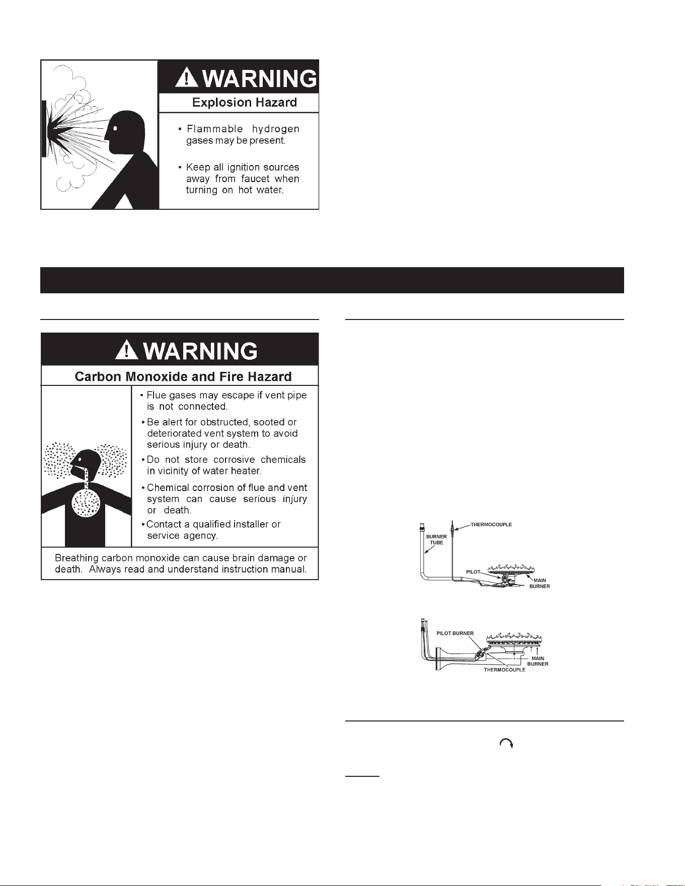
BURNER INSPECTION
Flood damage to a water heater may not be readily visible or
immediatelydetectable.However,overaperiodoftimeaooded
water heater will create dangerous conditions which can cause
DEATH, SERIOUS BODILY INJURY, OR PROPERTY DAMAGE.
Contactaqualiedinstallerorserviceagencytoreplaceaooded
waterheater.Donotattempttorepairtheunit!Itmustbereplaced!
Atleastonceayearavisualinspectionshouldbemadeofthemain
burnerandpilotburner,seeFigure19.
You should check for sooting.Soot is not normaland will impair
propercombustion.
Sootbuild-up indicates aproblem that requirescorrection before
furtheruse.Turn“OFF”gastowaterheaterandleaveoffuntilrepairs
aremade,becausefailuretocorrectthecauseofthesootingcan
resultinarecausingdeath,seriousinjury,orpropertydamage.
NATURAL
PROPANE
FIGURE 19.
BURNER CLEANING
Ifinspectionoftheburnershowsthatcleaningisrequired,turn
the gas control knob clockwise (
) tothe “OFF”position,
depressingslightly.
NOTE: The knob cannot be turned from “PILOT” to “OFF”
unless knob is depressed slightly. DO NOT FORCE.
Loosedepositsonoraroundtheburnercanberemovedbycarefully
usingthehoseofavacuumcleanerinsertedthroughtheaccessdoor
ofthewaterheater.Iftheburnerneedstoberemovedforadditional
cleaning,callaserviceagencytoremoveandcleantheburnerand
correcttheproblemthatrequiredtheburnertobecleaned.
23
ItisrecommendedthattheTemperature-PressureReliefValveshould
becheckedtoensurethatitisinoperatingconditionevery6months.
When checking theTemperature-Pressure Relief Valve operation,
makesurethat(1)noone isinfrontoforaround theoutletofthe
Temperature-PressureReliefValvedischargeline,and(2)thatthe
waterdischargewillnotcauseanypropertydamage,asthewater
maybeextremelyhot.Usecarewhenoperatingvalveasthevalve
maybehot.
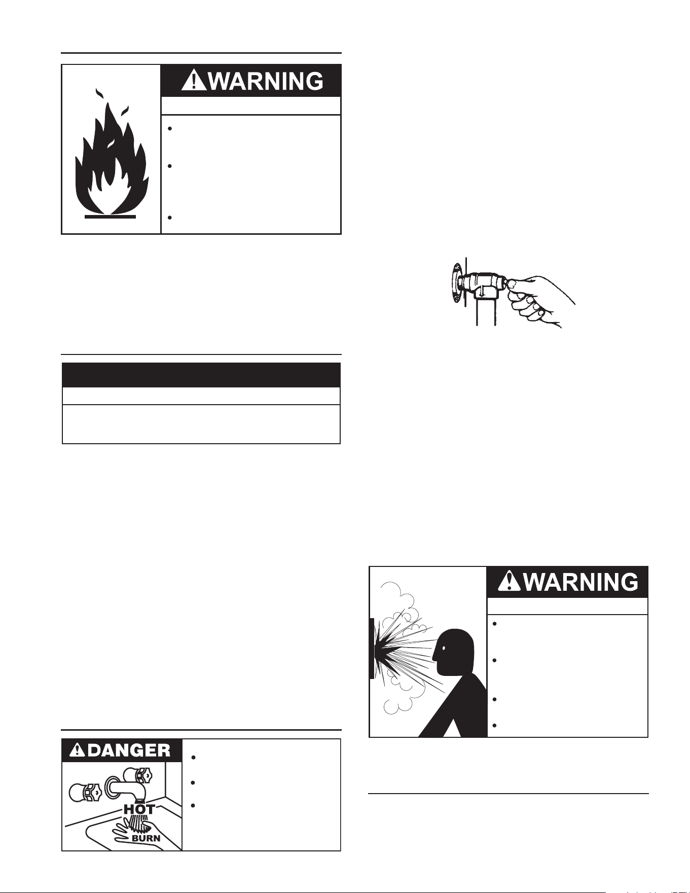
Tocheckthereliefvalve,lifttheleverattheendofthevalveseveral
times,seeFigure20.Thevalveshouldseatproperlyandoperatefreely.
Ifaftermanuallyoperatingthevalve,itfailstocompletelyreset
and continues to release water, immediately close the cold
waterinlettothewaterheateranddrainthewaterheater,see
DrainingAndFlushingonpage25.Replace theTemperature-
PressureReliefValvewithaproperlyrated/sizednewone,see
Temperature-PressureReliefValveonpage11forinstructions
onreplacement.
DISCHARGE PIPE
TEMPERATURE-PRESSURE
RELIEF VALVE
FIGURE 20.
IftheTemperature-PressureReliefValveonthewaterheater
weepsordischargesperiodically,thismaybeduetothermal
expansion.
NOTE: Excessive water pressure is the most common cause of
Temperature-Pressure Relief Valve leakage. Excessive water
system pressure is most often caused by “thermal expansion”
in a “closed system.” See Closed Water Systems and Thermal
Expansiononpage10.TheTemperature-PressureReliefValveis
notintendedfortheconstantreliefofthermalexpansion.
Temperature-PressureReliefValveleakageduetopressurebuild
up in a closed system that does not have a thermal expansion
tank installed isnotcovered under the limited warranty. Thermal
expansiontanksmustbeinstalledonallclosedwatersystems.
DO NOT PLUG THE TEMPERATURE-PRESSURE RELIEF
VALVE OPENING. THIS CAN CAUSE PROPERTY DAMAGE,
SERIOUS INJURY OR DEATH.
Explosion Hazard
Temperature-Pressure Relief Valve
must comply with ANSI Z21.22-
CSA 4.4 and ASME code.
Properly sized temperature-
pressure relief valve must be
installed in opening provided.
Can result in overheating and
excessive tank pressure.
Can cause serious injury or death.
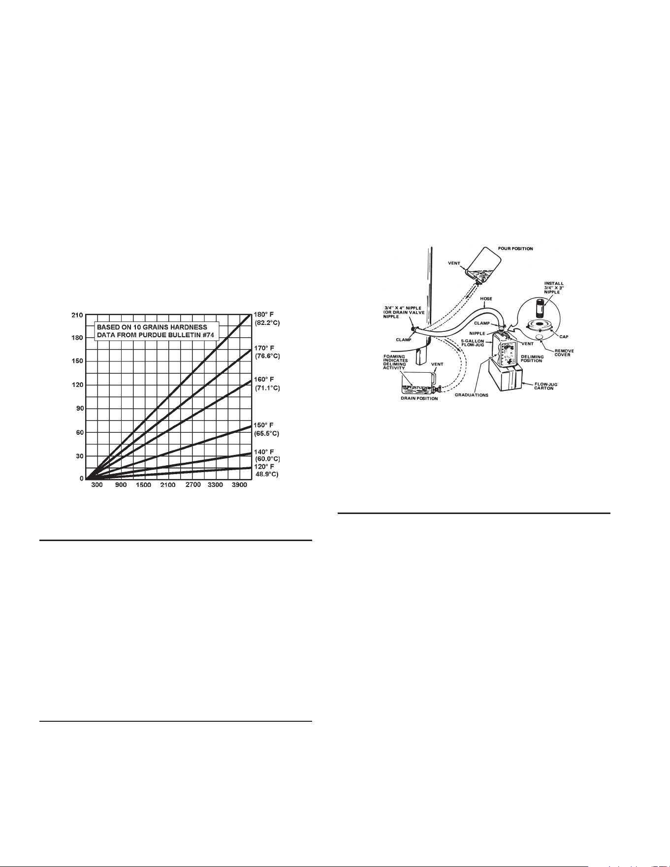
RECOMMENDED PROCEDURE FOR PERIODIC
REMOVAL OF LIME DEPOSITS FROM TANK TYPE
COMMERCIAL WATER HEATERS
Theamountofcalciumcarbonate(lime)releasedfromwaterisin
directproportiontowatertemperatureandusage,seechart.The
higherthewatertemperatureorwaterusage,themorelimedeposits
aredroppedoutofthewater.Thisisthelimescalewhichformsin
pipes,heatersandoncookingutensils.
HOUSEKEEPING
Fire and Explosion Hazard
Do not obstruct combustion air
openings at the bottom of the
water heater.
Do not use or store flammable vapor
products such as gasoline, solvents
or adhesives in the same room or area
near water heater or other appliance.
Can cause serious injury or death.
Vacuumaround base of water heater fordust,dirt, and lint on a
regularbasis.
INSTALLED IN SUITABLEAREA: To insure sufcient ventilation
andcombustionairsupply,properclearancesfromthewaterheater
mustbemaintained.See“LocatingtheNewWaterHeater”section.
Combustible materials such as clothing, cleaning materials, or
ammableliquids,etc.mustnotbeplacedagainstoradjacentto
thewaterheaterwhichcancauseare.
ANODE ROD INSPECTION
Property Damage Hazard
•
Avoid water heater damage.
•
Inspection and replacement of anode rod required.
CAUTION
Theanoderodisusedtoprotectthetankfromcorrosion.Mosthot
watertanksareequippedwithananoderod.Thesubmergedrod
sacricesitself toprotect thetank. Insteadof corrodingthe tank,
waterionsattackandeatawaytheanoderod.Thisdoesnotaffect
water’stasteorcolor.Therodmustbemaintainedtokeepthetank
inoperatingcondition.
Anodedeteriorationdependsonwaterconductivity,notnecessarily
watercondition.Acorrodedorpittedanoderodindicateshighwater
conductivityandshouldbecheckedand/orreplacedmoreoftenthan
ananoderodthatappearstobeintact.Replacementofadepleted
anoderodcanextendthelifeofyourwaterheater.Inspectionshould
beconductedbyaqualiedserviceagency,andataminimumshould
becheckedannuallyafterthewarrantyperiod.
Articially softened water is exceedingly corrosive because the
processsubstitutessodiumionsformagnesiumandcalciumions.
The use of a water softener may decrease the life of the water
heatertank.
Theanoderodshouldbeinspectedafteramaximumofthreeyears
andannuallythereafteruntiltheconditionoftheanoderoddictates
itsreplacement.
NOTE: Articially softened water requires the anode rod to be
inspectedannually.
TEMPERATURE-PRESSURE RELIEF VALVE TEST
Burn hazard.
Hot water discharge.
Keep clear of Temperature-
Pressure Relief Valve
discharge outlet.
24
Limeaccumulationnotonlyreducesthelifeoftheequipmentbut
alsoreducesefciencyoftheheaterandincreasesfuelconsumption.
The usage of water softening equipment greatly reduces the
hardnessofthewater. However,thisequipmentdoes notalways
removeallofthehardness(lime).Forthisreasonitisrecommended
thataregularschedulefordelimingbemaintained.
Thetimebetweencleaningwillvaryfromweekstomonthsdepending
uponwaterconditionsandusage.
Thedepthoflimebuildupshouldbemeasuredperiodically.Heaters
equippedwithcleanouts will have about 2”oflime buildup when
theleveloflimehasreachedthebottomofthecleanoutopening.A
schedulefordelimingshouldthenbesetup,basedontheamount
oftimeitwouldtakefora1”buildupoflime.Itisrecommendedthat
thewaterheaterinitiallybeinspectedafter6months.
Example1:
Initialinspectionafter6monthsshows1/2”oflimeaccumulation.
Therefore,theheatershouldbedelimedonceayear.
Example2:
Initialinspectionafter6monthsshows2”oflimeaccumulation.
Therefore,theheatershouldbedelimedevery3months.
FIGURE 21.
DELIMING SOLVENTS
UN•LIMEis recommendedfor deliming.UN•LIME isa patented
foodgradeacidwhichissafetohandleanddoesnotcreatethe
harmfulfumeswhichareassociatedwithotherproducts.
UN•LIMEmaybeobtainedfromyourdealer,distributororwater
heatermanufacturer.OrderPartNumber9005416105,1gallon,
packed 4 gallons per case or Part Number 9005417105, 5
galloncontainer.
NOTE:Un•LimeisnotavailableforuseinCanada.
Hydrochloric base acids are not recommended for use on glass
lined tanks.
Observehandlinginstructionsonlabelofproductbeingused.
TANK CLEANOUT PROCEDURE
Thefollowingpracticeswillensurelongerlifeandenabletheunitto
operateatitsdesignedefciency:
1. Onceamonththeheatershouldbeushed.Openthedrainvalve
andallowtwogallonsofwatertodrainfromtheheater.Inletwater
valveshouldremainopentomaintainpressureintank.
2. Acleanoutopeningisprovidedforperiodiccleaningofthetank.
Gasmustbeshutoffandheaterdrainedbeforeopeningcleanout.
Tocleanheaterthroughcleanoutopening,proceedasfollows:
1. Drainheater.
2. Removeoutercoverplatefromlowersideofheaterjacket.
3. Removesix(6)hexheadscrewssecuringtankcleanoutplate
andremoveplate.
4. Removelime,scale,orsedimentusingcarenottodamagethe
glasslining.
5. Inspect cleanout plate gasket, if new gasket is required, see
replacementpartslistforitemnumber.
6. Installcleanoutplate.Besuretodrawplateuptightbytightening
screwssecurely.
7. Replaceouterjacketcoverplate.
FIGURE 22.
9. In some water areas the sediment might not be removed
bythis method and may resultinthe water heater making
rumblingorboilingnoises.Todissolveandremovethesemore
stubborn mineral deposits, UN•LIME Professional Delimer
shouldbeused.
DELIMING USING FLO-JUG METHOD
UN•LIMEinthe5gallonsizeisrecommendedfordelimingofthe
BT-75 and100 models. UN•LIME with the necessary hoses and
ttingstodelimeyourheaterisalsoavailableasakit:Up-N-Down
TransferKit.Contactyourlocaldealer,distributororwaterheater
manufacturer.
PREPARE THE WATER HEATER
TodelimethewaterheaterusingtheFlo-Jugmethod,rstprepare
theheaterfordeliming.
PREPARE THE UP-N-DOWN TRANSFER KIT
ThenextstepisthepreparationontheUp-N-DownTransferKit,if
youhavenotalreadydoneso:
1. Withthe5gallonUp-N-Downcontainerintheverticalposition,
unscrew the plastic vent cap in the handle and pierce the
plasticmembraneovertheventbossunderthecaptoallowthe
containertovent.
Note: If yourcontainer doesnot havethe ventcap andvent
boss,drilla3/16”(4.76mm)holeinthehandle.Whenyouhave
nisheddelimingyouwillbeabletoplugthisdrilledventwiththe
stainlesssteelscrewthatissuppliedwiththekit.
2. Removethecontainer’scapandcutplasticmembranelocatedin
the3/4”IPTopeningincap.Takecaretonotdamagethethreads.
3. Findthe3/4”maleadapter,applyteontapetothethreadedend
andscrewitintothe3/4”IPTopeninginthecap.
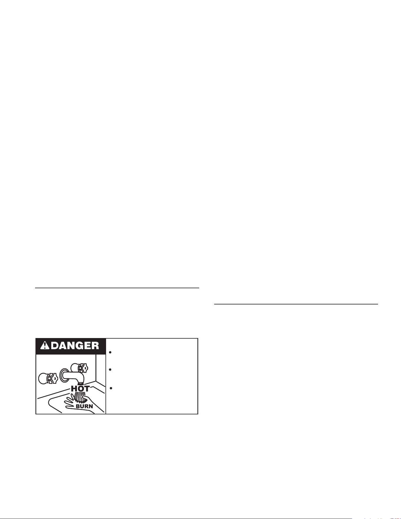
25
4. Putcapwithmaleadapterbackonthecontainerandslide3/4”
hoseoverendofmaleadapterandfasteninplaceusinghose
clampprovided.
DELIME USING FLO-JUG METHOD
5. Slidethehoseclampoverendofhoseandslidehoseoverthe
maleadapter inthe waterheater drainopening andsecure in
placeusinghoseclamp.
6. Liftcontainertothe“Pour”Positionbeingcarefultokeepthevent
inthehandleabovetheliquidlevelandpourtheUN•LIMEinto
theheater.
7. Lowercontainer,youmayhavetoplacethecontaineronitsempty
cartontopreventtheUN•LIMEfromowingbackintothecontainer.
8. LetUN•LIMEremainintheheaterfor5minutesandthenlower
thecontainertothe“Drain”Position.
9. Delimingactivityisindicated byfoamingon thesurfaceof the
UN•LIME.Ifthereisdelimingactivity,repeatsteps6thru8.
Normally,limeremovalwillbecompletedwithinonehour.Severe
build-upoflimemaytakelongerthananhourtocompletedescaling.
Note:TocheckUN•LIMEforcontinueduse,placesomescaleorwhite
chalkinaglasswithasmallamountofUN•LIME.Ifthematerialis
vigorouslydissolvedbytheUN•LIME,itcanbereused;ifnot,the
UN•LIMEshouldbereplaced.
Ifthe temperature-pressure reliefvalve on theapplianceweeps
ordischargesperiodically,thismaybeduetothermalexpansion.
Youmayhaveacheckvalveinstalledinthewaterlineorawater
meter with a check valve. Consult your local water supplier or
serviceagencyforfurtherinformation.Donotplugthetemperature-
pressurereliefvalve.
DRAINING AND FLUSHING
It is recommended that the water heater storage tank be
drained and ushed every 6 months to reduce sediment
buildup.Thewaterheatershouldbedrainedifbeingshutdown
duringfreezingtemperatures.SeeFeaturesAndComponents
inthismanualforthelocationofthewaterheatercomponents
describedbelow.
Burn harzard.
Hot water discharge.
Keep hands clear of drain
valve discharge.
TO DRAIN THE WATER HEATER STORAGE TANK:
1. Turnofftheelectricalsupplytothewaterheater.
2. TurnoffthegassupplyattheMainGasShutoffValveifthe
waterheaterisgoingtobeshutdownforanextendedperiod.
3. Ensurethecoldwaterinletvalveisopen.
4. Openanearbyhotwaterfaucetandletthewaterrununtil
thewaterisnolongerhot.
5. Closethecoldwaterinletvalvetothewaterheater.
6. Connect a hose to the water heater drain valve and
terminateittoanadequatedrain.
7. Openthewaterheaterdrainvalveandallowallthewaterto
drainfromthestoragetank.
8. Close the waterheater drain valve whenall water in the
storagetankhasdrained.
9. ClosethehotwaterfaucetopenedinStep4.
10. Ifthewaterheaterisgoingtobeshutdownforanextended
period,thedrainvalveshouldbeleftopen.
TO FLUSH THE WATER HEATER STORAGE TANK:
1. Turnofftheelectricalsupplytothewaterheater.
2. Ensurethecoldwaterinletvalveisopen.
3. Openanearbyhotwaterfaucetandletthewaterrununtil
thewaterisnolongerhot.Thenclosethehotwaterfaucet.
4. Connect a hose to the drain valveandterminateittoan
adequate drain.
5. Ensure the drain hose is secured before and during the
entire ushing procedure. Flushing is performed with
systemwaterpressureappliedtothewaterheater.
6. Openthewaterheaterdrainvalvetoushthestoragetank.
7. Flush the water heater storage tank to remove sediment
andallowthewatertoowuntilitrunsclean.
8. Close the water heater drain valve when ushing is
completed.
9. Removethedrainhose.
10. Fillthewaterheater-seeFillingTheWaterHeaterinthismanual.
11. Turnontheelectricalsupplytoplacethewaterheaterback
in operation.
12. TurnonthegassupplytothewaterheaterattheMainGas
ShutoffValve.
13. Allowthewaterheatertocompleteseveralheatingcycles
toensureitisoperatingproperly.
SERVICE
Beforecallingforrepairservice,readthe“StartUpConditions”and
“OperationalConditions”foundinthe“ForYourInformation”section
ofthismanual.
Ifaconditionpersistsoryouareuncertainabouttheoperationofthe
waterheatercontactaserviceagency.Ifyouarenotthoroughlyfamiliar
withgascodes,yourwaterheater,andsafetypractices,contactyour
gassupplierorqualiedinstallertocheckthewaterheater.
Use the ”Leakage Checkpoints” guide to check a “Leaking”
waterheater.Manysuspected“Leakers”arenotleakingtanks.Often
thesourceofthewatercanbefoundandcorrected.
Readthismanualrst.Thenbeforecheckingthewaterheatermake
surethegassupplyhasbeenturned“OFF”,andneverturnthegas
“ON”beforethetankiscompletelyfullofwater.
Neverusethiswaterheaterunlessitiscompletelylledwithwater.
Topreventdamagetothetank,thetankmustbelledwithwater.
Watermustowfromthehotwaterfaucetbeforeturning“ON”gas
tothewaterheater.
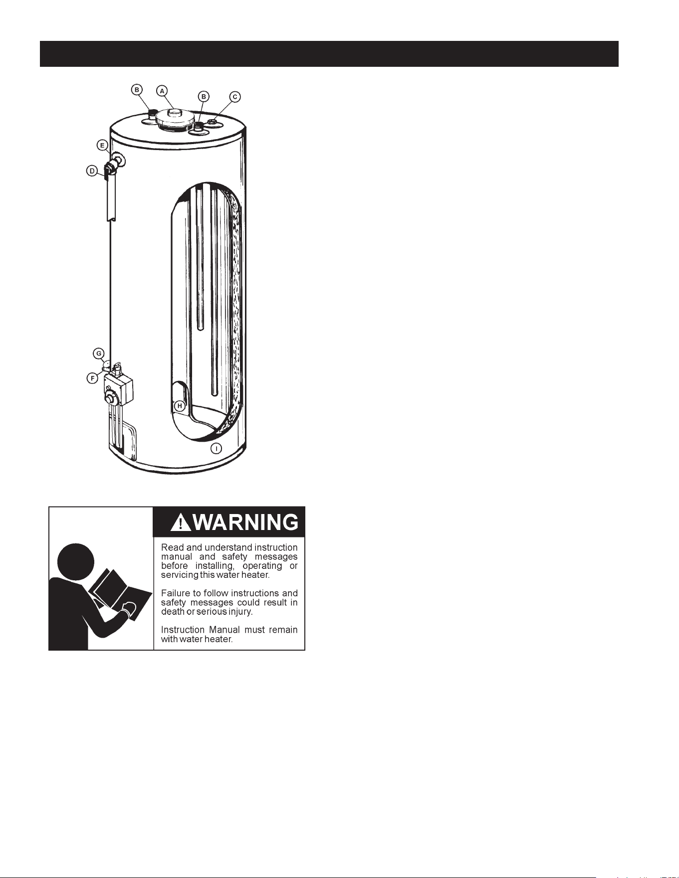
26
LEAKAGE CHECKPOINTS
A. Wateratthedrafthoodiswatervaporwhichhascondensedout
ofthecombustionproducts.Thisiscausedbyaprobleminthe
vent.Contactthegasutility.
B.*Condensationmaybeseenonpipesinhumidweatherorpipe
connectionsmaybeleaking.
C.*Theanoderodttingmaybeleaking.
D.Smallamountsofwaterfromtemperature-pressurereliefvalve
maybeduetothermalexpansionorhighwaterpressureinyour
area.
E.*The temperature-pressure relief valve may be leaking atthe
tanktting.
F.Waterfromadrainvalvemaybeduetothevalvebeingslightly
opened.
G.*Thedrainvalvemaybeleakingatthetanktting.
H.Combustionproductscontainwatervaporwhichcancondense
onthecoolersurfacesofthetank.Dropletsformanddriponto
theburnerorrunontheoor.Thisiscommonatthetimeof
start-upafterinstallationandwhenincomingwateriscold.
I. Waterinthewaterheaterbottomorontheoormaybefrom
condensation,looseconnections,orthereliefvalve.DONOT
replacethewaterheateruntilafullinspectionofallpossiblewater
sourcesismadeandnecessarycorrectivestepstaken.
Leakage from other appliances, water lines, or ground seepage
shouldalsobechecked.
* To check where threaded portion enters tank, insert cotton
swabbetweenjacketopeningandtting.Ifcottoniswet,follow
“Draining”instructionsinthe“PeriodicMaintenance”sectionand
thenremovetting.Putpipedopeorteontapeonthethreads
andreplace.Thenfollow“FillingtheWaterHeater”instructions
inthe“InstallingtheNewWaterHeater”section.
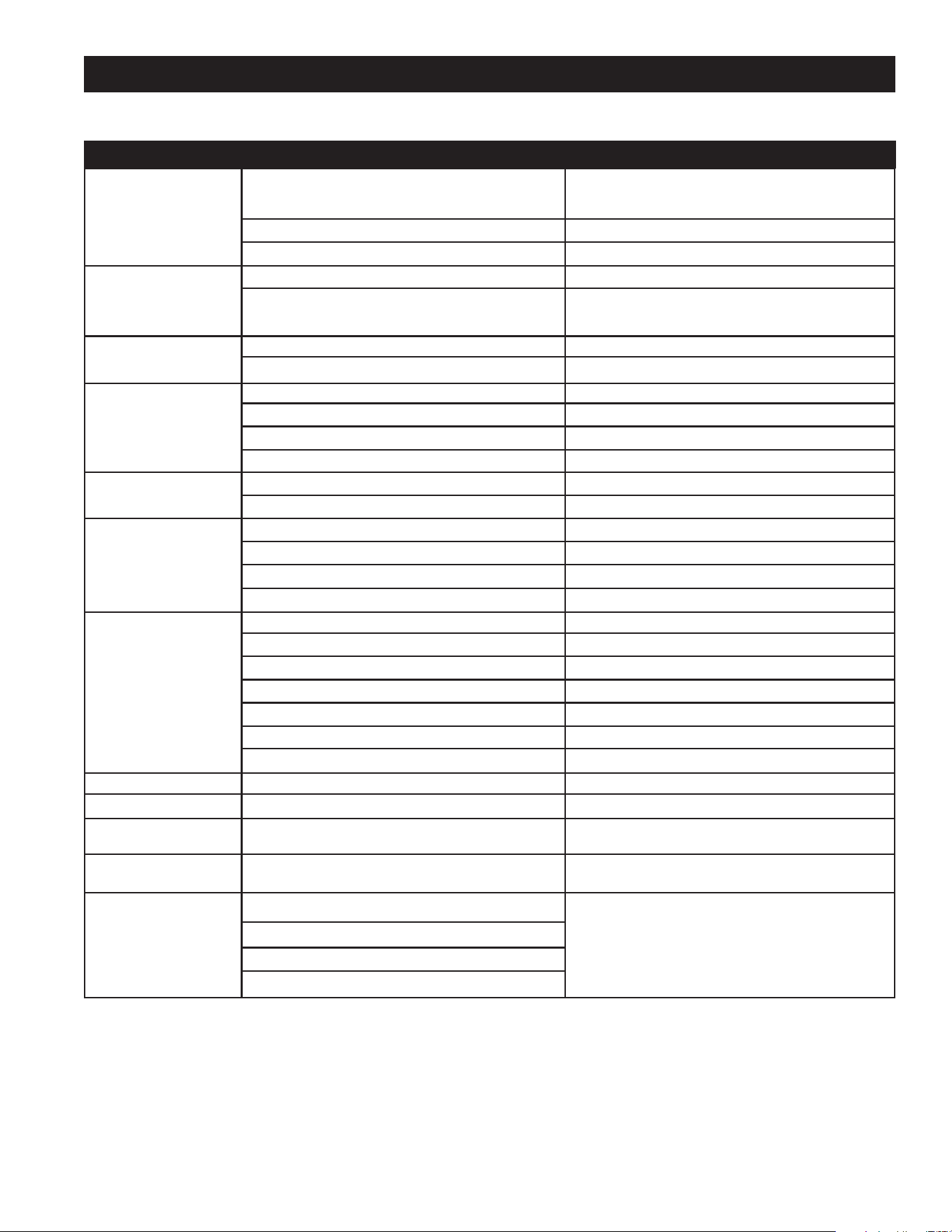
27
TROUBLESHOOTING GUIDELINES
Theseguidelinesshouldbeutilizedbyaqualiedserviceagent.
Problem Cause Solution
WATER LEAKS
Improperlysealed,hotorcoldsupplyconnection,relief
valve,drainvalve,orthermostatthreads.
Tightenthreadedconnections.
Leakagefromotherappliancesorwaterlines. Inspectotherappliancesnearwaterheater.
Condensationofueproducts. RefertoCONDENSATION.
LEAKING T&P VALVE
Thermalexpansioninclosedwatersystem. Installthermalexpansiontank(DONOTplugT&Pvalve).
Improperlyseatedvalve.
Checkreliefvalveforproperoperation
(DONOTplugT&Pvalve).
SMELLY WATER
Highsulfateormineralcontentinwatersupply. Drainandushheaterthoroughly,thenrell.
Bacteriainwatersupply. Chlorinateoraeratewatersupply.
PILOT WILL NOT LIGHT
Gascontrolknobnotpositionedcorrectly. RefertoLIGHTINGINSTRUCTIONS.
Maingassupplyoff. Turnonmaingasshutoffvalve.
Thermocouplemalfunction. Replacepilotassemblyand/orthermocouple.
No spark. Locatepiezoswitchonthermostat.Replaceifneeded.
BURNER WILL NOT
STAY LIT
Thermocouplemalfunction. Replacepilotassemblyand/orthermocouple.
DefectiveGasControl. ReplaceGasControl.
PILOT OUTAGE
Dirtypilotburner. Cleanpilotassembly.
Thermocouplemalfunction. Replacepilotassemblyand/orthermocouple.
DefectiveGasControl. ReplaceGasControl.
Thermocoupletipisnotincontactwithpilotame. Insertthermocouplecorrectly.
NOT ENOUGH
HOT WATER
Heaternotlitorthermostatnoton. RefertoLIGHTINGINSTRUCTIONS.
Thermostatsettoolow. RefertoTEMPERATUREREGULATION.
Heaterundersized. Reducehotwateruse.
Lowgaspressure. Contactyourgassupplier.
Incomingwaterisunusuallycold. Allowmoretimeforheatertore-heat.
Leakinghotwaterpipesorxtures. Haveplumbercheckandrepairleaks.
Hightemperaturelimitswitchactivated. Contactaserviceagencytodeterminecause.
WATER TOO HOT Thermostatsettoohigh. RefertoTEMPERATUREREGULATION.
WATER HEATER SOUNDS
Condensationdrippingonburner. RefertoCONDENSATION.
SIZZLINGOR
RUMBLING
Sedimentorcalciuminbottomofheatertank.
Cleansedimentfromtank.RefertoDRAINING
instructionsinMaintenancesectionofmanual.
SOOTING Impropercombustion.
Noadjustmentavailable.Contactaserviceagency
todeterminecause.
VENT GAS ODORS
Lackofsupplyair.
Contactaserviceagencytodeterminecause.
Improperlyinstalledventpiping.
Downdraft.
Poorcombustion.
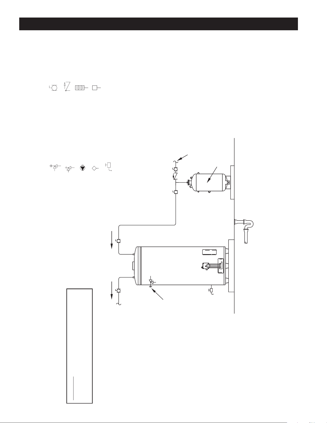
28
WATER PIPING DIAGRAMS
NOTES:
1. Preferred piping diagram.
2. The temperature and pressure relief valve setting shall not exceed pressure rating of any component in the system.
3. Service valves are shown for servicing unit. However, local codes shall govern their usage.
4. The Tank Te mperature Control should be wired to and control the pump between the water heater(s) and the storage tank(s).
SINGLE FLUE - (1 UNIT)
LEGEND
TEMPERATURE & PRESSURE
RELIEF VALVE
PRESSURE RELIEF VALVE
CIRCULATING PUMP
TANK TEMPERATURE CONTROL
DRAIN
FULL PORT BALL VALV
E
TEMPERATURE GAGE
WATER FLOW SWITCH
CHECK VALVE
WARNING: THIS DRAWING SHOWS SUGGESTED
PIPING CONFIGURATION AND OTHER DEVICES;
CHECK WITH LOCAL CODES AND ORDINANCES
FOR ADDITIONAL REQUIREMENTS.
FINISHED
FLOOR
HO CTOLD
COLD
EXPANSION
TANK
COLD WATER
SUPPLY
PIPE T&P TO
OPEN DRAIN
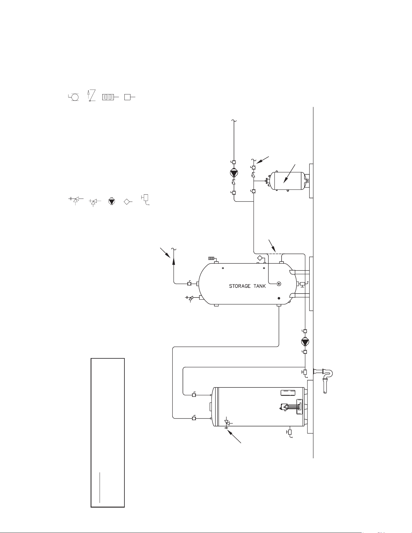
29
NOTES:
1. Preferred piping diagram.
2. The temperature and pressure relief valve setting shall not exceed pressure rating of any component in the system.
3. Service valves are shown for servicing unit. However, local codes shall govern their usage.
4. The Tank Temperature Control should be wired to and control the pump between the water heater(s) and the storage tank(s).
5. The water heater’s operating thermostat should be set 5 degrees F higher than the Tank Temperature Control.
SINGLE FLUE - (1 UNIT) WITH VERTICAL STORAGE TANK
LEGEND
TEMPERATURE & PRESSURE
RELIEF VALVE
PRESSURE RELIEF VALVE
CIRCULATING PUMP
TANK TEMPERATURE CONTROL
DRAIN
FULL PORT BALL VALVE
TEMPERATURE GAGE
WATER FLOW SWITCH
CHECK VALVE
WARNING: THIS DRAWING SHOWS SUGGESTED
PIPING CONFIGURATION AND OTHER DEVICES;
CHECK WITH LOCAL CODES AND ORDINANCES
FOR ADDITIONAL REQUIREMENTS.
FINISHED
FLOOR
HOT COLD
EXPANSION
TANK
COLD WATER
SUPPLY
HOT WATER
RETURN FROM
FIXTURES
HOT WATER
TO FIXTURES
ALT. COLD
WATER CONNECTION
PIPE T&P TO
OPEN DRAIN
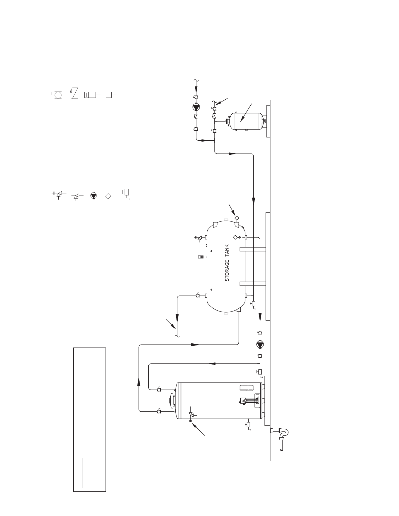
30
NOTES:
1. Preferred piping diagram.
2. The temperature and pressure relief valve setting shall not exceed pressure rating of any component in the system.
3. Service valves are shown for servicing unit. However, local codes shall govern their usage.
4. The Tank Temperature Control should be wired to and control the pump between the water heater(s) and the storage tank(s).
5. The water heater’s operating thermostat should be set 5 degrees F higher than the Tank Temperature Control.
SINGLE FLUE - (1 UNIT) WITH HORIZONTAL STORAGE TANK
LEGEND
TEMPERATURE & PRESSURE
RELIEF VALVE
PRESSURE RELIEF VALVE
CIRCULATING PUMP
TANK TEMPERATURE CONTROL
DRAIN
FULL PORT BALL VALVE
TEMPERATURE GAGE
WATER FLOW SWITCH
CHECK VALVE
WARNING: THIS DRAWING SHOWS SUGGESTED
PIPING CONFIGURATION AND OTHER DEVICES;
CHECK WITH LOCAL CODES AND ORDINANCES
FOR ADDITIONAL REQUIREMENTS.
FINISHED
FLOOR
HOT COLD
EXPANSION
TANK
COLD WATER
SUPPLY
HOT WATER
RETURN FROM
FIXTURES
HOT WATER
TO FIXTURES
ALTERNATE
LOCATION
PIPE T&P TO
OPEN DRAIN
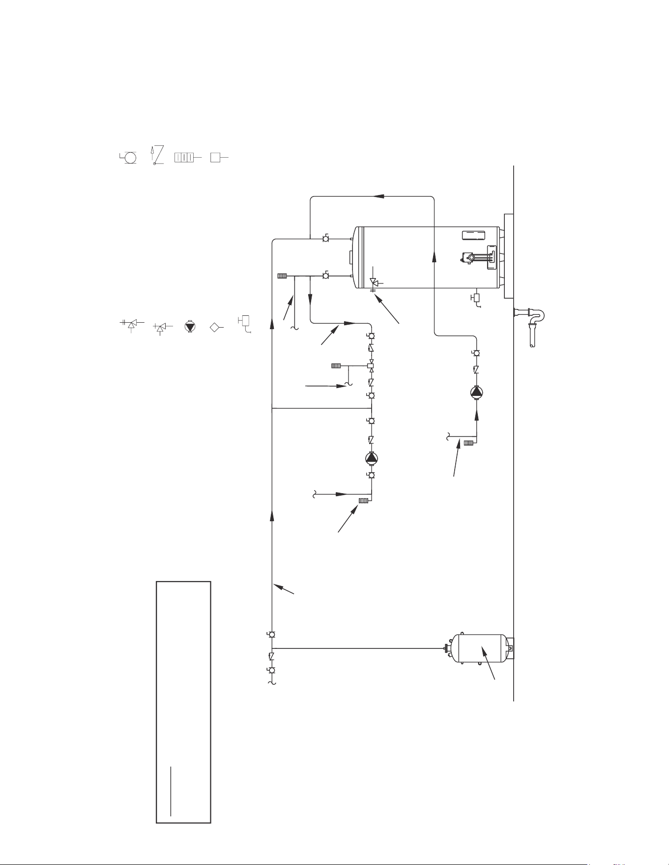
31
NOTES:
1. Preferred piping diagram.
2. The temperature and pressure relief valve setting shall not exceed pressure rating of any component in the system.
3. Service valves are shown for servicing unit. However, local codes shall govern their usage.
4. The Tank Temperature Control should be wired to and control the pump between the water heater(s) and the storage tank(s).
5. The water heater’s operating thermostat should be set 5 degrees F higher than the Tank Temperature Control.
SINGLE FLUE - (1 UNIT) WITH MIXING VALVE TWO TEMPERATURE
LEGEND
TEMPERATURE & PRESSURE
RELIEF VALVE
PRESSURE RELIEF VALVE
CIRCULATING PUMP
TANK TEMPERATURE CONTROL
DRAIN
FULL PORT BALL VALVE
TEMPERATURE GAGE
WATER FLOW SWITCH
CHECK VALVE
WARNING: THIS DRAWING SHOWS SUGGESTED
PIPING CONFIGURATION AND OTHER DEVICES;
CHECK WITH LOCAL CODES AND ORDINANCES
FOR ADDITIONAL REQUIREMENTS.
HOT WATER
RETURN
MINIMUM
10´´ to 12´´
HOT WATER OUTLET
TEMPERED
WATER
RETURN
TEMPERED
WATER
OUTLET
COLD WATER
SUPPLY
LINE
TEMPERATURE
CONTROL
COLDHOT
EXPANSION
TANK
PIPE T&P TO
OPEN DRAIN
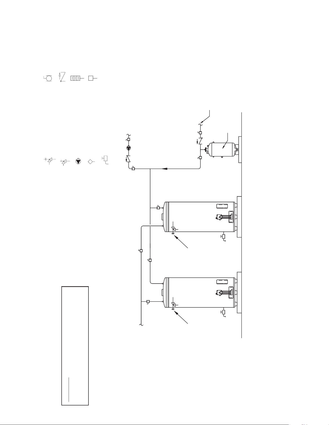
32
NOTES:
1. Preferred piping diagram.
2. The temperature and pressure relief valve setting shall not exceed pressure rating of any component in the system.
3. Service valves are shown for servicing unit. However, local codes shall govern their usage.
4. The Tank Temperature Control should be wired to and control the pump between the water heater(s) and the storage tank(s).
SINGLE FLUE - (2 UNITS)
LEGEND
TEMPERATURE & PRESSURE
RELIEF VALVE
PRESSURE RELIEF VALVE
CIRCULATING PUMP
TANK TEMPERATURE CONTROL
DRAIN
FULL PORT BALL VALVE
TEMPERATURE GAGE
WATER FLOW SWITCH
CHECK VALVE
WARNING: THIS DRAWING SHOWS SUGGESTED
PIPING CONFIGURATION AND OTHER DEVICES;
CHECK WITH LOCAL CODES AND ORDINANCES
FOR ADDITIONAL REQUIREMENTS.
FINISHED
FLOOR
HOT WATER
TO FIXTURES
HOT COL HD OT
HOT WATER RETURN
FROM FIXTURES
COLD
COLD WATER
SUPPLY
EXPANSION
TANK
PIPE T&P TO
OPEN DRAIN
PIPE T&P TO
OPEN DRAIN
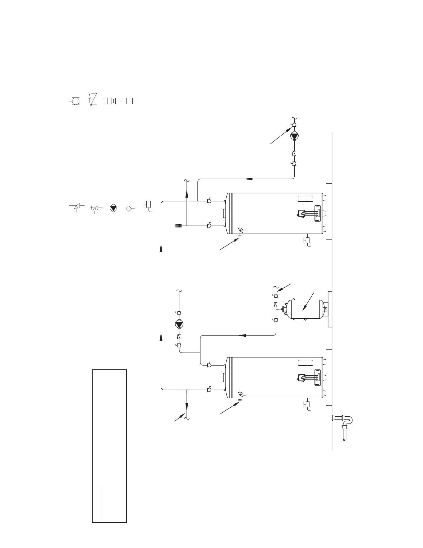
33
NOTES:
1. Preferred piping diagram.
2. The temperature and pressure relief valve setting shall not exceed pressure rating of any component in the system.
3. Service valves are shown for servicing unit. However, local codes shall govern their usage.
SINGLE FLUE - (2 UNITS) TWO TEMPERATURE ONE PRE-HEATER/ONE BOOSTER HEATER
LEGEND
TEMPERATURE & PRESSURE
RELIEF VALVE
PRESSURE RELIEF VALVE
CIRCULATING PUMP
TANK TEMPERATURE CONTROL
DRAIN
FULL PORT BALL VALVE
TEMPERATURE GAGE
WATER FLOW SWITCH
CHECK VALVE
WARNING: THIS DRAWING SHOWS SUGGESTED
PIPING CONFIGURATION AND OTHER DEVICES;
CHECK WITH LOCAL CODES AND ORDINANCES
FOR ADDITIONAL REQUIREMENTS.
FINISHED
FLOOR
HOT WATER
TO FIXTURES
HOT WATER RETURN
HOT HOTCOLD
HIGH
TEMPERATURE
RETURN
HIGH
TEMPERATURE
OUTLET
COLD WATER
SUPPLY
EXPANSION
TANK
PIPE T&P TO
OPEN DRAIN
PIPE T&P TO
OPEN DRAIN
BOOSTER
HEATER

34
NOTES

35
EFFECTIVE
For 3 Years, intheeventofatankleak,wewillrepairor,atour
discretion,replacethedefectivewaterheater.
For 1 Year, intheeventofpartfailure,wewillrepairor,atour
discretion,replacethedefectivepart.
We warrant this product against defects in materials or
workmanship as described in this document if installed within
theUnitedStatesorCanadaandprovidedtheproductremains
atitsoriginalplaceofinstallation.
WarrantycoveragebeginsthedateofinstallationORthedateof
manufactureifinstallationcannotbeveried.
WHAT'S COVERED
Subjecttotheseterms,intheeventofdefectinmaterialsand/
orworkmanshipresulting inatank leak duringtherst three
years,wewill:
• Replacethewaterheatershouldthetankleak.
Subjecttotheseterms,intheeventofadefectinmaterialsand/or
workmanshipappearingduringtherst year,wewill:
• Repair or, at our discretion, replace any part of the water
heater covered under this limited warranty excluding parts
subject to normal maintenance (Example: non-electronic
anoderod,lter,etc)
Service/labor, shipping, delivery, installation, handling or any
other costs are not covered at any time under this warranty.
Any replacement part or product will be warranted only for
the unexpired portion of the original water heater’s limited
warrantyperiod.
Ifanidenticalmodelisnolongeravailableduetoachangeinlaw,
regulation,orstandard,wewillreplacetheproductwithonehaving
comparablecapacityandinput.Intheseinstances,theownerwill
havetheoptionofpayingthedifferencebetweenwhatwaspaidfor
theoriginalmodelandthenewmodelwiththeadditionalfeatures,
orreceivinga refund of the portion ofthe purchase price, on a
pro-ratabasisallocabletotheunexpiredportionofthewarranty.
WHAT'S NOT COVERED
• Problemscausedbyimproper:gassupplylinesizing,gastype,
venting,connections,combustionair,voltage,wiring,orfusing
•Failuretofollowapplicablecodes
•Failuretofollowprintedinstructions
•Abuse,misuse,accident,re,ood,ActsofGod
•Improperinstallation,sizing,delivery,ormaintenance
•Claimsrelatedtorust,noise,smell,ortasteofwater
•Failuretoconductauthorizedfactorystartupifrequired
•Alterationstothewaterheater
•Non-outdoorheatersinstalledoutdoors
•Damagesduetoafailuretoallowforthermalexpansion
• Heatexchangerfailureduetolackofadequate/propersupply
ofwater
•Heatersmovedfromtheiroriginallocation
•Servicetripstoexplainproperinstallation,use,ormaintenance
of the product/unit or to describe compliance requirements
underapplicablecodesandregulations
• Charges related to accessing your heater including but not
limitedtodoor/wallremoval,equipmentrental,etc.
•Replacementpartsafterexpirationofthiswarranty
LIMITATIONS
NOTWITHSTANDING ANYTHING ELSE TO THE CONTRARY,
THIS IS YOUR SOLE AND EXCLUSIVE WARRANTY.
ALL OTHER WARRANTIES INCLUDING A WARRANTY
OF MERCHANTABILITY OR FITNESS FOR PARTICULAR
PURPOSE ARE EXPRESSLY DISCLAIMED. SELLER SHALL
NOT BE LIABLE FOR ANY CONSEQUENTIAL, INCIDENTAL,
SPECIAL, PUNITIVE OR OTHER INDIRECT DAMAGES. TOTAL
LIABILITY ARISING AT ANY TIME SHALL NOT EXCEED THE
PURCHASE PRICE PAID WHETHER BASED ON CONTRACT,
TORT, STRICT LIABILITY OR ANY OTHER LEGAL THEORY.
SERVICE INQUIRIES:
For service inquiries call the telephone number listed below. Bepreparedtoprovidethefollowinginformation:
name,address,andtelephonenumber;themodelandserialnumberofthewaterheater;proofofinstallation;andacleardescription
oftheproblem.
Foryourrecords,fillintheproduct:
Serial:___________________
Model:___________________
U.S.Customers: CanadianCustomers:
A. O. Smith Corporation P. O. Box 310 – 768 Erie Street
500 Tennessee Waltz Parkway Stratford (Ontario) N5A 6T3
Ashland City, Tennessee 37015 800-265-8520
800-527-1953
COMMERCIAL
WATER HEATER
LIMITED WARRANTY

36