Chatsworth, CA 91311, USA
(888) 275-3352
www.perimost.com
P E R I M O S T . C O M
F5006

To avoid possible electric shock, turn off the electricity at the main fuse box or circuit panel before
youbegin the fan installation or before servicing the fan or installing accessories.
Read all instructions and safety information carefuly before installing your fan and save these instruc-
tions.
Make sure all electrical connections comply with local codes or ordinances and the National Electrical-
Code. lf you are unfamiliar with electric wiring, please use a qualified and licensed electrician.
Make sure you have a location selected for your fan that allow clear space for the blades to rotate,and
atleast seven (7) feet of clearance betweem the floor and the fan blade tips. The fan should be mount-
ed atleaet thirty (30) inches ftom walls or other upright structures.
WARNING: The outlet box and ceiling support joist used must be securely mounted, and capable
ofsupporting at least 100 pounds. To reduce the risk of fire, electric shock or personal injury, mount to
theoutlet box marked acceptable for fan supported and use mounting screws provided with the outlet
box.The box must be supported directly by the building structure.
WARNING: To reduce the risk of fire, electric shock or personal injury, mount to outlet box marked“ac-
ceptable for fan support" and use mounting screws provided with the outlet box most outlet boxescom-
monly used for the support of lighting fixtures are not acceptable for fan support and may need to
bereplaced. Consult a qualified electrician if in doubt.
Electrical diagrams are for reference only. Light kits that are not packed with the fan must UL listed
andmarked suitable for use with the model fan you are installing. Switches must be UL. general use
switches.Refer to the instructions packaged with the light kits and switches for proper assembly.
After installation is complete, check that al connections are absolutely secure
After making electrical connections, spliced conductors should be tumed upward and pushed carefuly
upinto outlet box. The wires should be spread apart with the grounded conductor and the equip-
ment-grounding conductor on one side of the outlet box.
WARNING: To reduce the risk of electrical shock and fire, do not use this fan with any solid-state
fanspeed control device, or rheostat.
Do not separate the reverse switch until the fan has come to a complete stop.
Do not insert anything into the fan blades while they are rotating.
WARNING: To reduce the risk of personal injury, do not bend the blade brackets (also referred to
as"anges") during assembly or after installation. Do not insert objects in the path of the blades.
To avoid personal injury or damsge to the fan and other items,be cautious when working around
orcleaning the fan.
Do not use water or detergent when cleaning the fan or fan blades. A dry dust cloth or lightly damp-
enedcloth will be suitable for most cleaning.
SAFETY TIP
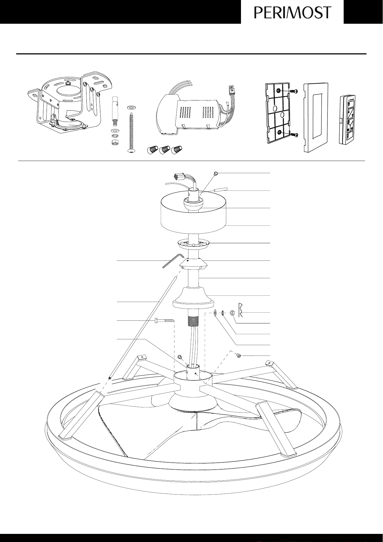
Wire nut (3pcs)
Controller Remote
Mounting Bracket
(4pcs) Expansion Bolts
(4pcs) Self Tapping Screw
Canopy
Nut
Clevis pin
Flat Washer
Spring Washer
Coupling cover
Canopy Ring
15” Downrod
Screw
Lock Pin
Hanger Ball
Coupling
Set Screws
Bolt
Connecting station
Pole
Allen Wrench
Basic Product Parameters
Care And Clean
FCC Statement
SKU
Fan Blade Span
Maximum Airflow
Maximum Noise
F5006
22”
2600CFM
55db(A)
Voltage
Rated Wattage
RPM
Number of rotating blades
110-120 VAC
30W
88-330rmp
3 blades
1. Check the support connections, brackets, and airfoil attachments twice a year. Make sure theyaresecure.
Because of the fan's natural movement, some connections may become loose over timeltis not necessary
to remove the fan from the ceiling.
2. Clean your fan periodically. Use only a soft brush or lint-free cloth to avoid scratching the finishThe
plating is sealed with a lacquer to minimize discoloration or tarnishing.
3. (Optional) Apply a light coat of furniture polish to the wood blades.
4. (Optional) Cover small scratches with a light application of shoe polish.
Do Not:
1. Use water when cleaning. Water could damage the motor, or the wood, or possibly causeanelectrical
shock.
2. Apply oil to your fan or motor, The motor has permanently lubricated sealed ball bearingsNote:Poweroff
the fan before product maintenance or cleaning the fan.
Note:Power off the fan before product maintenance or cleaning the fan.
NOTE:This equipment has been tested and found to comply with the limits for a Class B digitadevicepursu-
ant to part 15 of the FCC Rules, These limits are designed to provide reasonableprotection againstharmful
interference in a residential installation. This equipment generates.uses and can radiate radiofrequency
energy and, if not installed and used in accordance withthe instructions, may cause harmfulinterference to
radio communications. However, there is noguarantee that interference will not occur in aparticular installa-
tion. f this equipment does causeharmful interference to radio or television reception,which can be deter-
mined by turning theequipment off and on, the user is encouraged to try to correct theinterference by one or
more of the following measures:
- Reorient or relocate the receiving antenna.
- increase the separation between the equipment and receiver.
- Connect the equipment into an outlet on a circuit different from that to which the receiver isconnectedCon-
sult the dealer or an experienced radio/TV technician for help.
WARNING: Changes or modifications to this unit not expressly approved by the party responsibleforcompli-
ance could void the user's authority to operate the equipment.
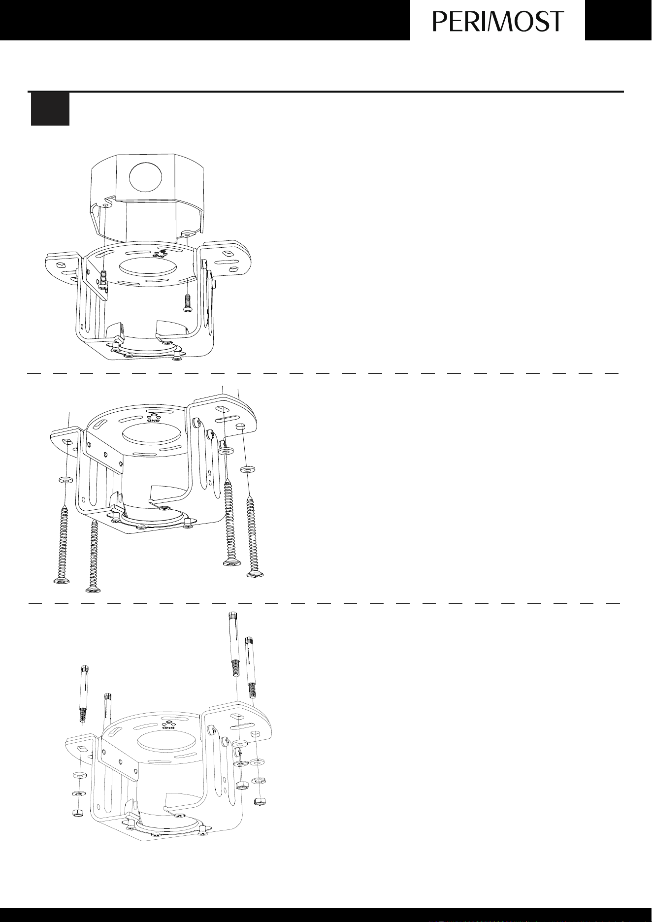
ASSEMBLYINSTRUCTION
OUTLET BOX
1
WOODEN CEILING
CONCRETE CEILING
Install the mounting bracket onto Outlet Box
marked (acceptable for fan support of 15.9 kg(35
lbs) or less) with Mounting Screws.
Use the Mounting Bracket as a guide, drill 4 holes
for 3MM diameter, install the mounting bracket
onto wooden ceiling with the 4 Self Tapping
Screws & Washers.
Use the Mounting Bracket as a guide, drill 4 holes
and insert 4 Expansion Bolts into the concrete
ceiling, install the mounting bracket and secure
with Flat Washers, Spring Washers and Nuts.
ASSEMBLYINSTRUCTION
1
2
3
4
1
2
1
3
4
5
6
3
4
2
7
1
2
5
6
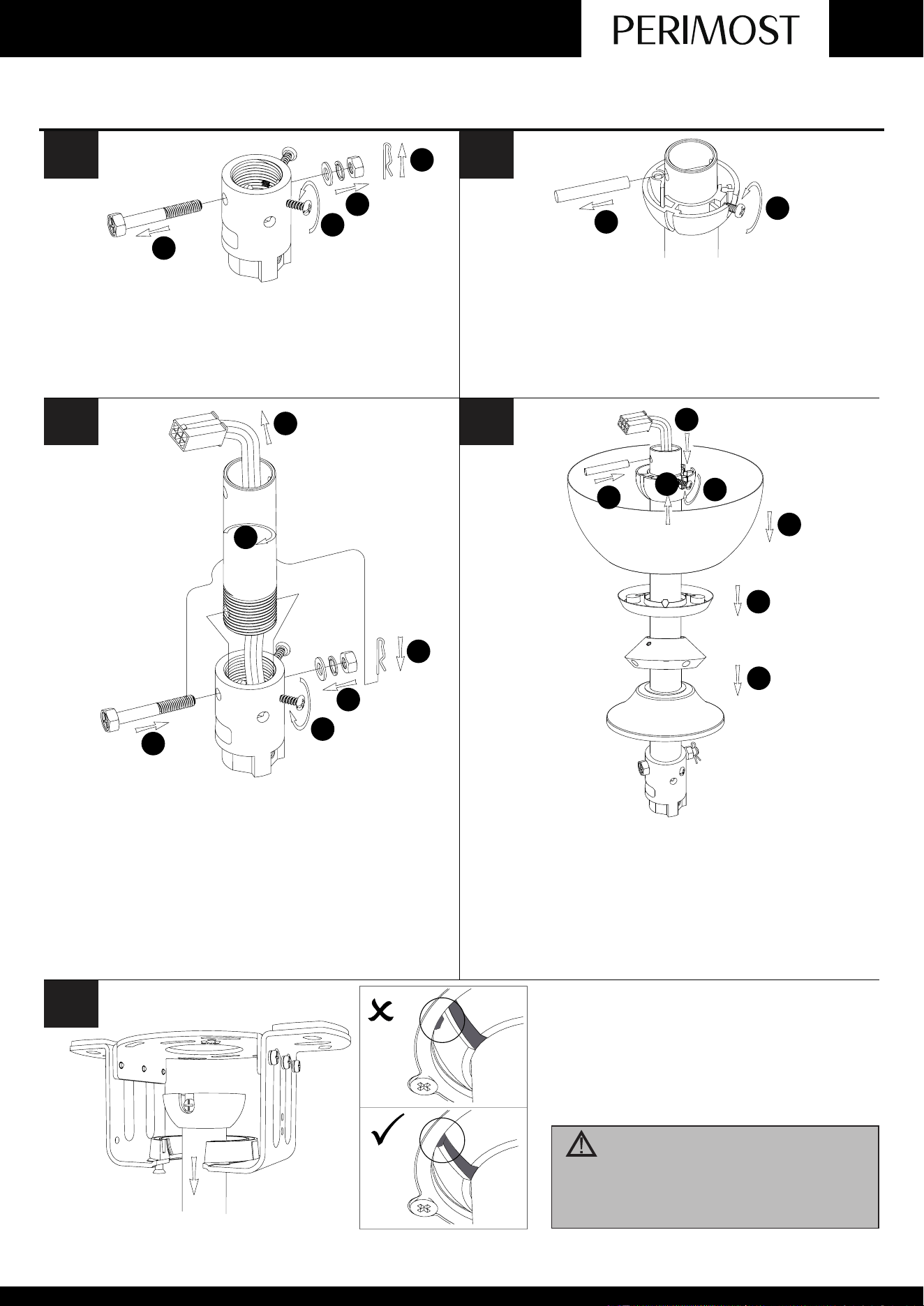
Loosen the Screws and Remove the Clevis
Pin, Nut, Spring Washers, Flat Washers & Bolt
on Coupling.
Loosen the Screw from Hanger Ball, remove
the Hanger Ball and Lock Pin.
Route the wires and safety wire from the motor
through the Downrod. Install the Downrod to
Coupling and secure with Bolt, Flat Washer,
Spring Washer, Nut & Clevis pin. Tighten the 2
Set Screws on the Coupling.
Route the Coupling cover (Connecting station),
Canopy Ring, Canopy and Hanger Ball through
the Downrod in turn, and then install the Lock pin
through the hole on the Downrod. Slip the hanger
ball upward to lock Pin, and fix it by Screw, then
slip down the Coupling Cover in correct position.
2
3
4 5
IMPORTANT : THE DOWNROD
AND HANGER BALL SHOULD
NOT ROTATE IF THIS STEP IS
DONECORRECTLY.
Raise the fan and place the hanger ball
onto mounting bracket. Rotate the fan
until the notch on hanger ball snapped
into the slot on mounting bracket and
sits firmly.
6
ASSEMBLYINSTRUCTION
7 8
1
2
3
4
FROM POWER SOURCE
AC 110-120VOLT 60Hz 3.5AMPS.
9
1
2
3
4
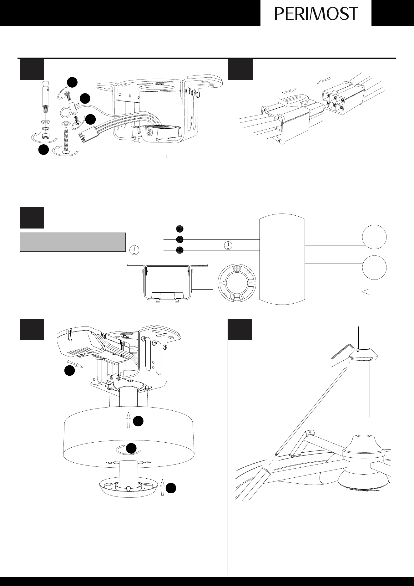
Tighten the safety wire clamp. Place ring of safety
wire through the expansion bolt or self tapping screw
and fix it to the building structure.
Connect the wire connector plugs
correctly. The wire connector plugs design
with fool proof device, please don’t force to
plug. Otherwise it may affect the normal
use of the light fan or burn the fan motor.
Insert the controller into the mounting bracket, and
tidy up the wiring. Push the canopy to the mounting
bracket, make two sliding holes aligned to the two
prominent screws on the mounting bracket, and then
turn clockwise until tight. Push the canopy ring to the
canopy.
Connect wires from
controller to power supply
with wire connectors.
10
MOTOR U
AC IN L
AC IN N
MOTOR V
MOTOR W
LIGHT N
LIGHT L
Hanger Ball
Mounting Bracket
Antenna
Light
Fan
G
Live
Neutral
Earth
Controller
(Receiver)
11
Screw the pole into the square tube, slide
the connecting station upwards, insert the
pole into the hole of the connecting
station, and fix the connecting station
with allen wrench.
Connecting station
Pole
Allen Wrench
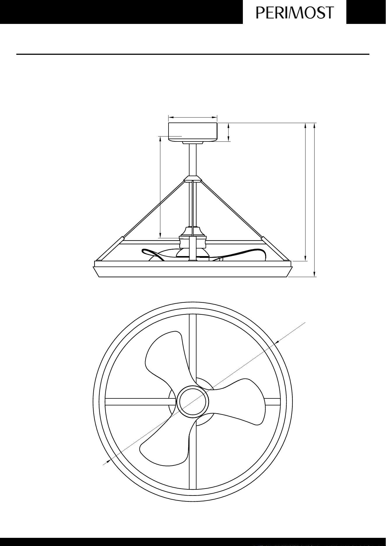
FAN DIAMETER EFFECT
Ø7.3 in
2.8 in
15 in
20.8 in
23.2 in
Ø
30.1 in
OPERATING YOUR FAN
REMOTE CONTROL SETTING AND OPERATION
Turn on the power and check the fan's operation.
The appropriate speed settings of warm or cool weather depend on many factorssuch as the room size,
ceiling height, and fans' number.
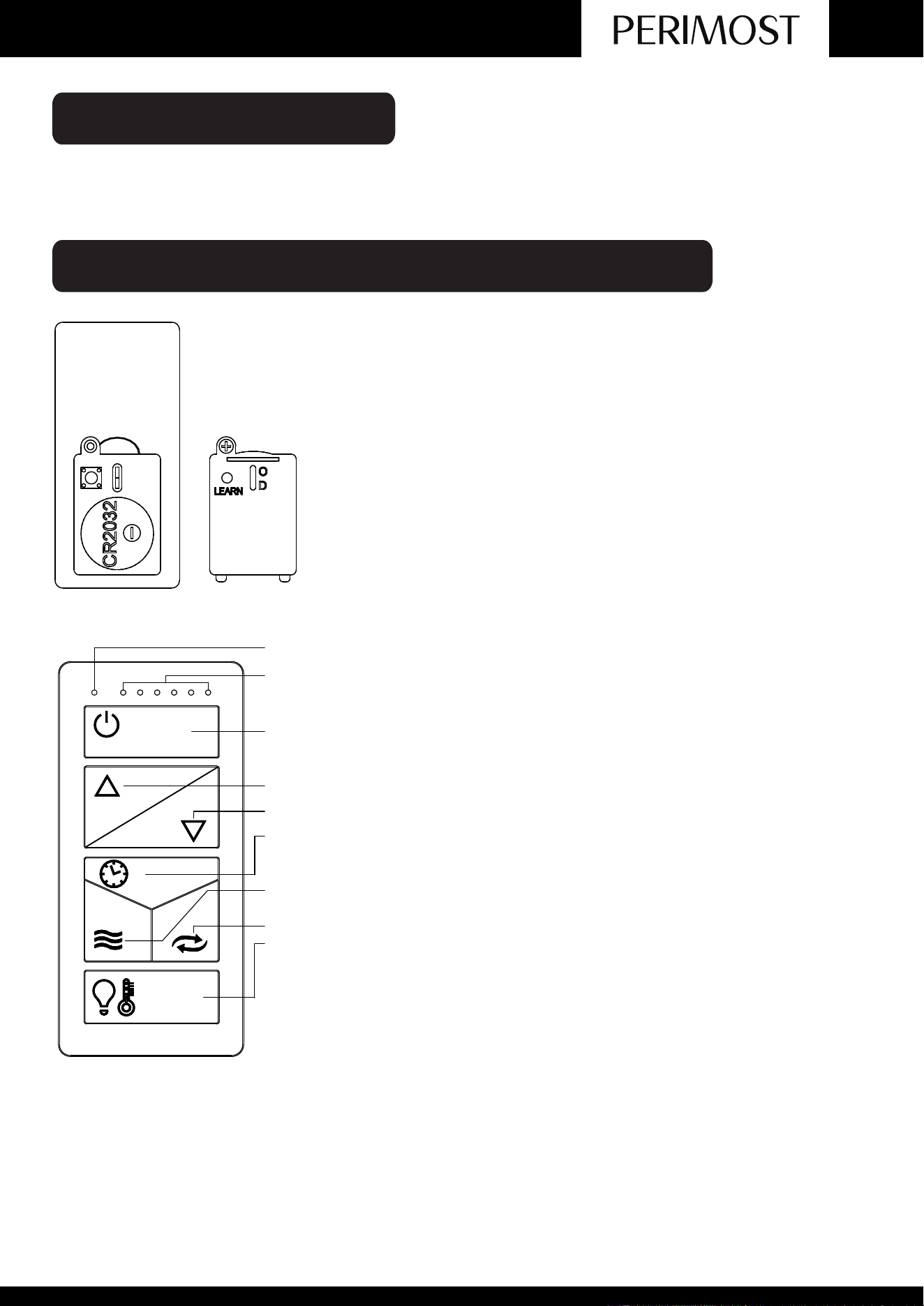
1) The battery is pre-installed and can be used by removing the
insulation paper. Open the REMOTE battery cover and install DC3V
battery (Model: CR2032) when replacing the battery.
2) Turn on the power of the light fan.
3) Within 30 sec after the “Beep”, press and hold the LEARN button for 3
sec. (Don’t press any other buttons.) Once the receiver has detected
and learned the frequency, the receiver will “Beep” twice mean while
the light will bright out twice.
4) Programming/self-learning process is completed and REMOTE is
ready to use.
5) Dial up to position “D”, the brightness of the light can be control low or
high. NOTE: This option is not applicable for non-dimming products.
Operating Indicator
Fan Speed Indicator (1~6) Timing Indicator (1, 3, 6hr)
Turns off the fan
Fan speed control (increasing)
Fan speed control (decreasing)
Timing the fan (Autooffafter1/3/6hrs)
Natural Wind:
Fan speed changes within its range creating gentle natural wind effect.
Forward or reverse operation: change fan rotating direction.
Light control
When the OD switch down to the position of "D", Press the button one time to
turn on or turn off the light, long press bottom adjustable light, dimmer in the
process, when the light bulbs reach to most bright and dark, have a "Beep"
sound tip respectively.
When the OD switch up to the position of “O” and the light is on, long press
the button adjustable color temperature.
ATTENTION
1) After completing the steps above, you should be able to operate the fan and light. If the fan and light
are not responding to the REMOTE, please turn the power off to the light fan and repeat step 2 and 3.
2) When not used for extended periods of time, remove battery to extend lifespan.
Memory Function: if the power supply of the product is disconnected during use, and the power supply is
switched on again, the fan will continue to operate according to the state before power off, and the light will
be turned on by default.
TROUBLESHOOTING
Try these troubleshooting steps before contacting the Customer Service. For additional operation.
maintenance,and troubleshooting information, please contact our customer service center.
SYMPTOM POSSIBLE SOLUTION
Fan not spinning
Fan not spinning
The fan is noisy
and wobbling
Unable to pair
remote and app
(Only for smart
Fan)
Fan or light
turning on or off
by themselves
1. Make sure the fan is getting power.
2. Check your circuit breaker or fuse panel and wall switch for functionality.
3. Fan wires areconnecting with the house wires correctly.
4. Remote control must be paired with the fan within 10 minutesafter the fan getting power,
5. lf you have paired the app but the fan still didn't work (light and fan both didn't work) orcouldn't pair the
app tothe fan, try to reset the fan: to reset the fan, cut the power for 10minutes,then tum the power on
and press thepairing buttonon the remote for 5 secondstill hear beep sound, then pair the Carrohome
app again.
6. Use a multi-meter and test the adapter wiring hamess to see if there is any electrical output.
7. All the pin wiring on the circuit board ar inserted tight and in the right position.
8. Remote need to pair with the fan first
9. Make sure the fan blades spin freely.
10. lf you're using a wall control, check the power to the breaker from your control and tryworking your
celling fanmanually.(Normal switch only for the fan power on/off)
1. Make sure LED wires are connected to the circuit board.
2. Make sure the whole fan is powered.
3. Remote need to pair with the fan first,correctly and in the retention slot.
1. Check if the wires are connected in the right position or not.
2. Check the batteries in the remote.
3. Disconnect the power for 10 minutes, reconnect the power and pair the remote with thefan immediately,
within 5 seconds. Also try pairing the App to reconnect.
4. The WiFi must be 2.4Ghz, incompatible with 5Ghz WiFior combine with 5Ghz.
5. App must in the new version.
6. Connect with correct app"Vaczon Home
1. Check if the blade screws are NOT rubbing against the round plastic part of the motor.
2. Check the pin wire are NOT connected against the moving part.
3. Check the down fan cup is NOT hitting the motor.
4. Confirm the canopy is NOT touching the ceiling while the fan is in operation
5. Check the down rod is NOT slanted.
6. Tighten any loose screws on the light kit, fan blades, motor coupling. down rod. brackets and mounting
hardware
7. Confirm the hanger ball is firmly seated in the mounting bracket.
8. The ceiling beam must meet the minimum tensile test strength of 30KG for installation.
9. Make sure the airfoils and brackets are NOT bent or deformed.
10. Verify the wire connections are not rattling against each other.
11. Verify the fan blades are not cracked. lf the fan blades are cracked, replace the damagedblades with a
newblade set from the same brand as your ceiling fan to ensure compatibility.
12. The light kit is NOT slanting and hitting the motor.
1. Confirm the circuit breaker is not malfunctioning
2. Verify the wire connections are not frayed.
3. Check the app is not set the timer or schedule
4. Cut the fan power for 10 minutes then power on again.
5. All the pins wiring on the circuit board are inserted tight and in the right position


PERIMOST.COM