
Operator's Manual 1
©Copyright 2013 #37-1261-E/S-121923
C
201473
OPERATOR'S MANUAL FOR
PORTABLE
GASOLINE DRIVEN/DIRECT DRIVE
TOP FIRED OIL HEATED
HOT WATER PRESSURE WASHERS
®
US
CAUTION
RISK OF INJURY!
READ MANUAL BEFORE OPERATING!
This manual is an important part of the pressure washer and must
remain with the unit when you sell or rent it!

2 Operator's Manual
WARNING: This product can expose you to
chemicals including Lead, which is known to
the State of California to cause cancer and birth
defects or other reproductive harm. For more
information go to www.P65Warnings.ca.gov
WARNING
WARNING: This product can expose you to
chemicals including carbon monoxide, which is
known to the State of California to cause birth
defects or other reproductive harm. For more
information go to www.P65Warnings.ca.gov
WARNING
TABLE OF CONTENTS
INTRODUCTION .............................................................................................................3
SAFETY WARNINGS ....................................................................................................... 4
RISK OF EXPLOSION OR FIRE .................................................................................................................4
RISK OF ASPHYXIATION ...........................................................................................................................4
RISK OF INJECTION OR SEVERE CUTTING INJURY ..............................................................................5
RISK OF ELECTROCUTION OR ELECTRICAL SHOCK ...........................................................................5
RISK OF BURNS ........................................................................................................................................5
RISK OF BURSTING .................................................................................................................................. 5
RISK FROM MOVING PARTS .................................................................................................................... 6
RISK OF BODILY INJURY .......................................................................................................................... 6
SMALL FRAME FEATURES ............................................................................................8
FEATURES LISTING ........................................................................................................9
LARGE FRAME FEATURES ..........................................................................................10
FEATURES LISTING ......................................................................................................11
INSTALLATION & PREPARATION ................................................................................12
ATTIRE: ....................................................................................................................................................12
SET-UP: ...................................................................................................................................................12
ENGINE/BURNER FUEL TANK: ............................................................................................................... 12
DUAL LANCE ASSEMBLY WITH ADJUSTABLE PRESSURE: ................................................................. 13
DUAL LANCE CONNECTION: .................................................................................................................13
WATER SUPPLY: ......................................................................................................................................13
UNLOADER: ............................................................................................................................................14
THERMAL RELIEVE VALVE: .....................................................................................................................14
PRE-START INSPECTION PROCEDURES: ............................................................................................. 14
OPERATING INSTRUCTIONS ......................................................................................16
PRIMING THE PUMP: ..............................................................................................................................16
START-UP/COLD WATER OPERATION: ..................................................................................................16
HOT WATER OPERATION:.......................................................................................................................17
CLEANING WITH DETERGENTS UNDER LOW PRESSURE: .................................................................17
SHUT-DOWN: ..........................................................................................................................................18
STORAGE & MAINTENANCE ....................................................................................... 19
SPECIFIC MAINTENANCE: .....................................................................................................................19
WINTERIZING: ......................................................................................................................................... 20
MAINTENANCE CHART ...............................................................................................24
ACCESSORIES ..............................................................................................................25
STATEMENT OF WARRANTY ......................................................................................26
NOTES ...........................................................................................................................27
Operator's Manual 3
INTRODUCTION
Congratulations on the purchase of your new hot water pressure washer featuring the patented Electro Magnetic
Firing (EMF) System! You can be assured your new hot water pressure washer was constructed and designed with
quality and performance in mind. Each component has been rigorously tested to ensure the highest level of accep-
tance.
This operator's manual was compiled for your benet. By reading and following the simple safety, installation,
operation, maintenance and troubleshooting steps described in this manual, you will receive years of trouble free
operation from your new hot water pressure washer. The contents of this manual are based on the latest product
information available at the time of publication. The manufacturer reserves the right to make changes in price, color,
materials, equipment, specications or models at any time without notice.
! IMPORTANT !
These paragraphs are surrounded by a "SAFETY ALERT BOX". This box is used to designate and emphasize
Safety Warnings that must be followed when operating this pressure washer. Accompanying the Safety Warn-
ings are "signal words" which designate the degree or level of hazard seriousness. The "signal words" used in
this manual are as follows:
DANGER: INDICATES AN IMMINENTLY HAZARDOUS SITUATION WHICH, IF NOT AVOIDED, WILL
RESULT IN DEATH OR SERIOUS INJURY.
WARNING: INDICATES A POTENTIALLY HAZARDOUS SITUATION WHICH, IF NOT AVOIDED, COULD
RESULT IN DEATH OR SERIOUS INJURY.
CAUTION: INDICATES A POTENTIALLY HAZARDOUS SITUATION WHICH, IF NOT AVOIDED MAY RESULT
IN MINOR OR MODERATE INJURY.
The symbols set to the left of this paragraph are "Safety Alert Symbols". These symbols are used to call atten-
tion to items or procedures that could be dangerous to you or other persons using this equipment.
ALWAYS PROVIDE A COPY OF THIS MANUAL TO ANYONE USING THIS EQUIPMENT. READ ALL INSTRUC-
TIONS BEFORE OPERATING THIS PRESSURE WASHER AND ESPECIALLY POINT OUT THE "SAFETY WARN-
INGS" TO PREVENT THE POSSIBILITY OF PERSONAL INJURY TO THE OPERATOR.
Once the unit has been uncrated, immediately write in the serial number of your unit in the space provided below.
SERIAL NUMBER_________________________________
Inspect for signs of obvious or concealed freight damage. If damage does exist, le a claim with the transportation
company immediately. Be sure that all damaged parts are replaced and that the mechanical and electrical problems
are corrected prior to operation of the unit. If you require service, contact Customer Service.
Please have the following information available for all service calls:
1. Model Number
2. Serial Number
3. Date and Place of Purchase
4 Operator's Manual
SAFETY WARNINGS
RISK OF EXPLOSION OR FIRE
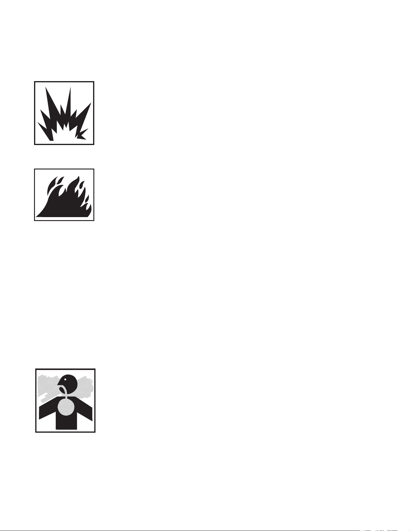
Serious injury or death may occur from normal sparks in the multiple ignition
sources or engine/burner exhaust.
Always operate pressure washer in a well ventilated area free of ammable
vapors, combustible dust, gases or other combustible materials.
Do not store the pressure washer near an open ame or any equipment
such as a stove, furnace, water heater, etc., which utilizes a pilot light or
sparking device.
Do not use this pressure washer to spray ammable material!
Serious injury or death may occur as a result of improper fueling.
Do not smoke while lling fuel tanks.
Never ll the fuel tanks while the engine is running or hot. Allow the engine
to cool two minutes before refueling.
Do not refuel indoors or in a poorly ventilated area.
Always refuel slowly to avoid the possibility of spilled fuel which may cause
a risk of re.
Engine Fuel Tank: If using a Gasoline Engine, refuel with gasoline only. Do
not use diesel or fuel oil.
Burner Fuel Tank (Black): When refueling the Burner Fuel Tank, use No. 1 or
No. 2 fuel oil/diesel or kerosene. Do not use gasoline.
Do not operate the unit if gasoline or diesel fuel is spilled. Wipe the pressure
washer clean and move it away from the spill. Avoid creating any ignition
until the gasoline or diesel fuel has evaporated.
Serious injury or death may occur from a ground re caused by a mufer
spark.
A spark arrester must be added to the mufer of this engine if it is to be
used on any forest covered, brush covered or grass covered unimproved
land. The arrester must be maintained in effective working order by the op-
erator. In the state of California, the above is required by law. (Section 4442
of the California Public Resources Code.) Other states may have similar
laws. Federal laws apply on Federal lands.
Serious injury or death may occur if system safety's are not properly main-
tained.
This pressure washer has a Safety Relief device which should never be
altered, modied, removed or made inoperative. If the device fails, replace
immediately with only genuine manufacturer replacement part.
RISK OF ASPHYXIATION
Serious injury or death may occur from inhaling engine/burner exhaust or
dangerous vapors. The engine exhaust from this product contains chemi-
cals known to the State of California to cause cancer, birth defects, or other
reproductive harm.
This pressure washer was designed for outdoor use only. Never operate
this pressure washer in an enclosed area. Always make certain there is
adequate ventilation (fresh outside air) for breathing and combustion. This
will prevent the buildup of dangerous carbon monoxide gases. Beware of
poorly ventilated areas, or areas with exhaust fans which can cause poor air
exchange.
Follow all safety instructions provided with the materials you are spraying.
Use of a respirator may be required when working with some materials. Do
not use this pressure washer to dispense hazardous detergents.
Operator's Manual 5
SAFETY WARNINGS
RISK OF INJECTION OR SEVERE CUTTING INJURY
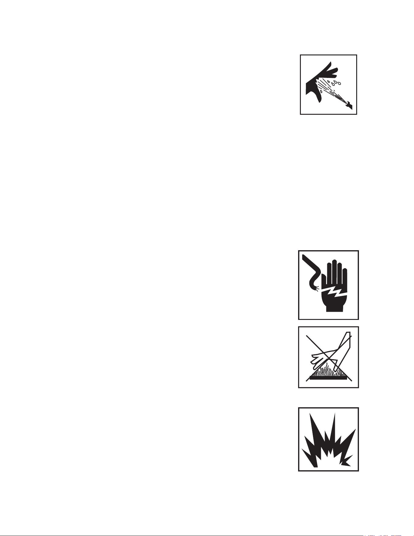
Serious injury or death could occur from high pressure spray penetrating the
skin.
Keep clear of nozzle and spray! Never put your hand, ngers or body di-
rectly over the spray nozzle.
Never point the high pressure discharge spray at yourself or anyone else.
Always keep operating area clear of all persons.
DO NOT allow children to operate this unit.
SEEK EMERGENCY MEDICAL CARE if the spray appears to have penetrat-
ed the skin! DO NOT TREAT AS A SIMPLE CUT!!
High pressure hoses and fuel lines should be inspected daily for signs of
wear. If evidence of failure exists, promptly replace all suspect hoses and
fuel lines to prevent the possibility of injury from the high pressure spray. If
a hose or tting is leaking, NEVER PLACE YOUR HAND DIRECTLY ON THE
LEAK.
NEVER operate the gun with the trigger wired in the open position. To pre-
vent accidental discharge, the trigger gun should be securely locked when
not in use.
Before removing the spray nozzle or servicing the unit, ALWAYS shut off the
unit and trigger the gun to release trapped pressure. (Even after you shut off
the unit, there is high
pressure water left in the pump, hose and gun until you release it by trigger-
ing the gun.)
RISK OF ELECTROCUTION OR ELECTRICAL SHOCK
Serious injury or death may occur from contact with electricity.
DO NOT direct spray on or into electrical installations of any kind! This in-
cludes electrical outlets, light bulbs, fuse boxes, transformers, the unit itself,
etc.
DO NOT allow metal components of the pressure washer to come in contact
with live electrical components.
RISK OF BURNS
Serious injury may occur from touching the gasoline engine, mufer or heat
exchanger. These areas can remain hot for some time after the pressure
washer is shutdown.
Never allow any part of your body to contact the gasoline engine, mufer or
heat exchanger.
RISK OF BURSTING
Serious injury may occur from a pressure washer malfunction or exploding
accessories if incorrect system components, attachments or accessories
are used.
Never make adjustments to the factory set pressures.
Never exceed manufacturers maximum allowable pressure rating of attach-
ments.
Do not allow any hoses to make contact with the engine mufer, gasoline
engine or heat exchanger to prevent the possibility of bursting. Avoid drag-
ging the hoses over abrasive surfaces such as cement.
Use only genuine manufacturer recommended repair parts for your pressure
washer.
6 Operator's Manual
Serious injury or death may occur if attempting to start the pressure washer
when the pump is frozen.
In freezing temperatures, the unit must always be warm enough to ensure
there is no ice formation in the pump. Do not start the pressure washer if it
has been transported in an open or underheated vehicle without rst allow-
ing the pump to thaw.
RISK FROM MOVING PARTS
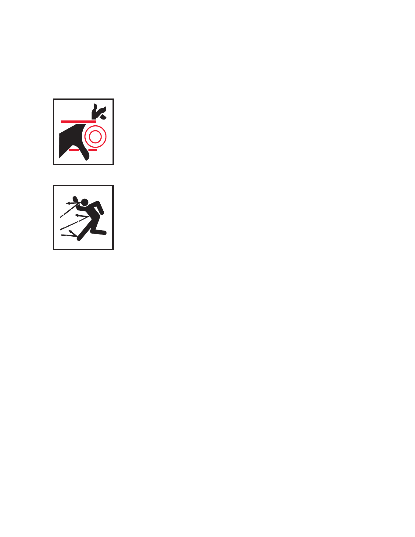
Serious injury may occur to the operator from moving parts on the pressure
washer.
Before making any adjustments, be certain the engine is turned off and the
ignition cable(s) is removed from the spark plug(s). Turning the machinery
over by hand during adjustment or cleaning might start the engine and ma-
chinery with it.
Do not operate the unit without all protective covers in place.
RISK OF BODILY INJURY
Serious injury or death may occur from detergents contacting the skin.
SEEK EMERGENCY MEDICAL CARE if you are using cleaning agents and
the spray appears to have penetrated the skin! DO NOT TREAT AS A SIM-
PLE CUT! Be prepared to tell a physician exactly what kind of detergents
you were using by reading the Material Safety Data Sheet (MSDS) provided
with your detergent.
Never use any solvents or highly corrosive detergents or acid type cleaners
with this pressure washer.
Protective equipment such as rubber suits, gloves and respirators are ad-
visable, especially when using cleaning detergents.
Keep all detergents out of the reach of children!
Serious injury can occur from loose debris being propelled at a high speed
from the spray gun.
ALWAYS wear protective goggles when operating the unit to shield the eyes
from ying debris and detergents.
DO NOT direct spray toward fragile materials such as glass for shattering
could occur.
Injury may occur if the operator loses his balance caused by the thrust of
water traveling through the spray nozzle.
Stay alert-watch what you are doing. Do not operate the unit when fatigued
or under the inuence of alcohol or drugs.
NEVER squeeze the trigger unless securely braced.
DO NOT overreach or stand on unstable support.
Wet surfaces can be slippery, wear protective foot gear and keep good foot-
ing and balance at all times.
NEVER trigger the gun while on a ladder or roof.
ALWAYS hold on rmly to the gun/lance assembly when starting and operat-
ing the unit. Failure to do so can cause the lance to fall and whip danger-
ously.
Injury may occur from the pressure washer.
Know how to stop the pressure washer and bleed pressures quickly. Be
thoroughly familiar with controls.
DO NOT leave pressurized unit unattended. Shut off the pressure washer
and release trapped pressure before leaving.
SAFETY WARNINGS

Operator's Manual 7
SAFETY WARNINGS
DO NOT operate the unit if you see any fuel, oil or water leaks from the
machine. DO NOT resume operation until the unit has been inspected and
repaired by a qualied service person.
NEVER run the engine with the governor disconnected or operate at exces-
sive speeds.
Place unit in a clean, dry, at area for servicing. Before servicing the unit:
turn the unit off, relieve the water pressure from the trigger gun, and allow
the unit to cool down. Service in clean, dry, at area. If applicable, block
wheels to prevent unit from moving.
Do not move the unit by pulling on the hose.
!SAVE THESE INSTRUCTIONS!
8 Operator's Manual
HSP SMALL FEATURES-022713-CH
SMALL FRAME FEATURES

Operator's Manual 9
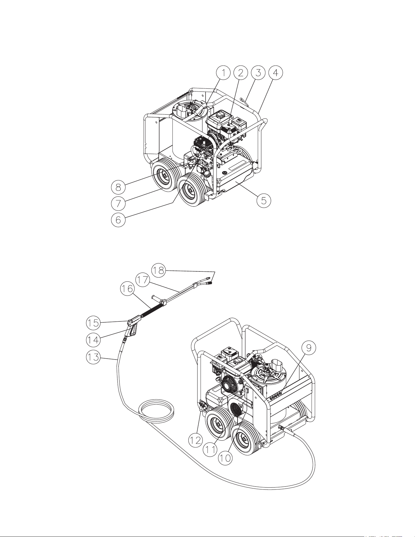
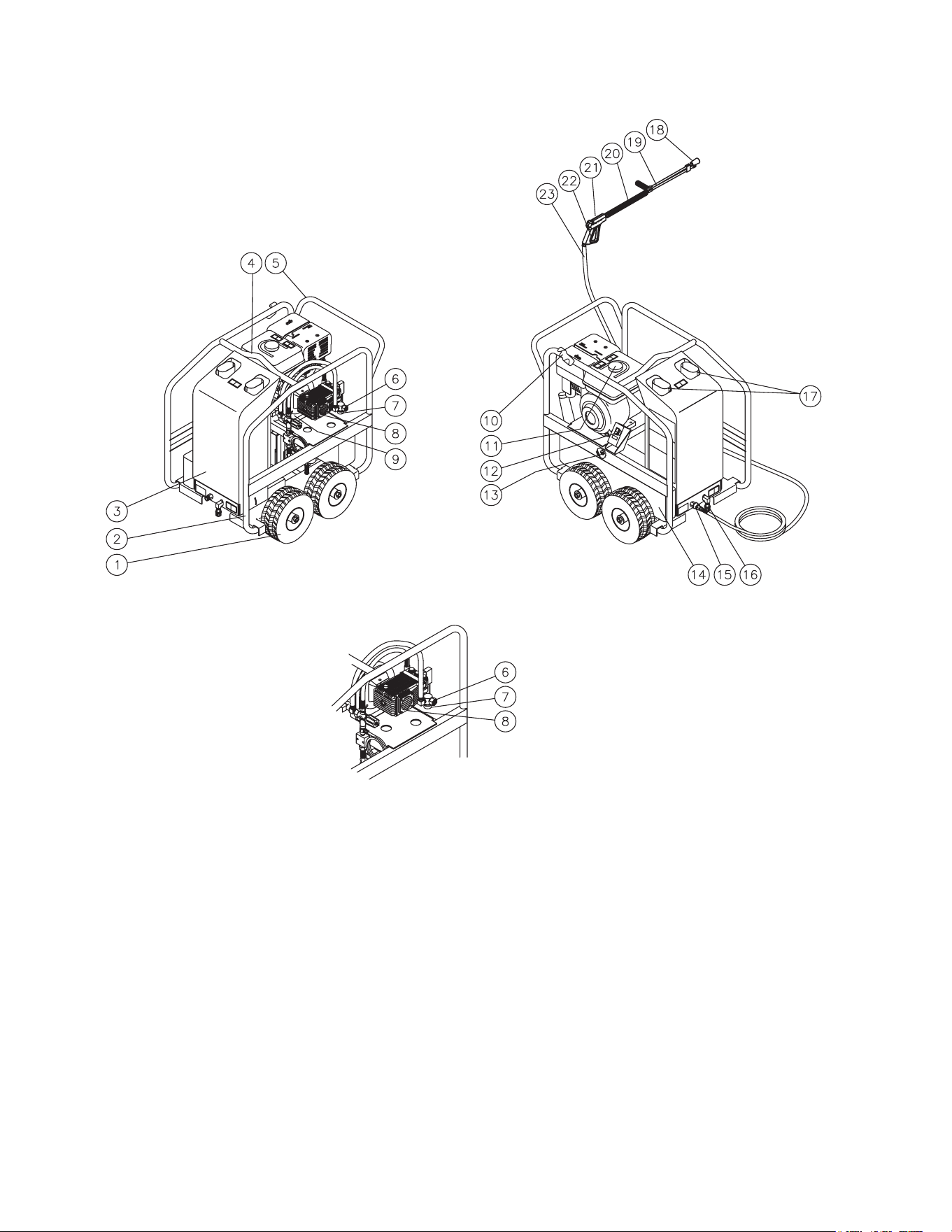
1. Center Balanced Lifting Eye
2. Engine Gasoline Tank
3. Wand Holder
4. Protective Rollcage
5. Burner Fuel Tank
6. High Pressure Pump
7. Flat Free Wheels
8. Fuel Filter/Water Seperator
9. Spray Nozzle Holder
10. Burner On/Off Switch
11. Burner Air Regulation
12. Brake
13. High Pressure Hose
14. Trigger Safety Lock
15. Trigger Gun
16. Insulated Lance
17. Adjustable Pressure Dual Lance
18. Nozzle
FEATURES LISTING
10 Operator's Manual
OMHSP044-012612-CH
LARGE FRAME FEATURES

Operator's Manual 11
1. Pneumatic Wheels
2. Protective Rollcage
3. Protective Cover
4. Center Balanced Lifting Eye
5. Convenient Push/Pull Handle
6. Water Inlet
7. Water Strainer
8. High Pressure Pump
9. Beltguard
10. Wand Holder
11. Engine Gasoline Tank
12. Burner On/Off Switch
13. Air Shutter Adjusting Arm
14. Burner Fuel Tank
15. High Pressure Outlet
16. Coil Drain Assembly
17. Heat Exchanger Exhaust
18. Nozzle
19. Adjustable Pressure Dual Lance
20. Insulated Lance
21. Trigger Gun
22. Trigger Safety Lock
23. High Pressure Hose
FEATURES LISTING
12 Operator's Manual
INSTALLATION & PREPARATION
ATTIRE:
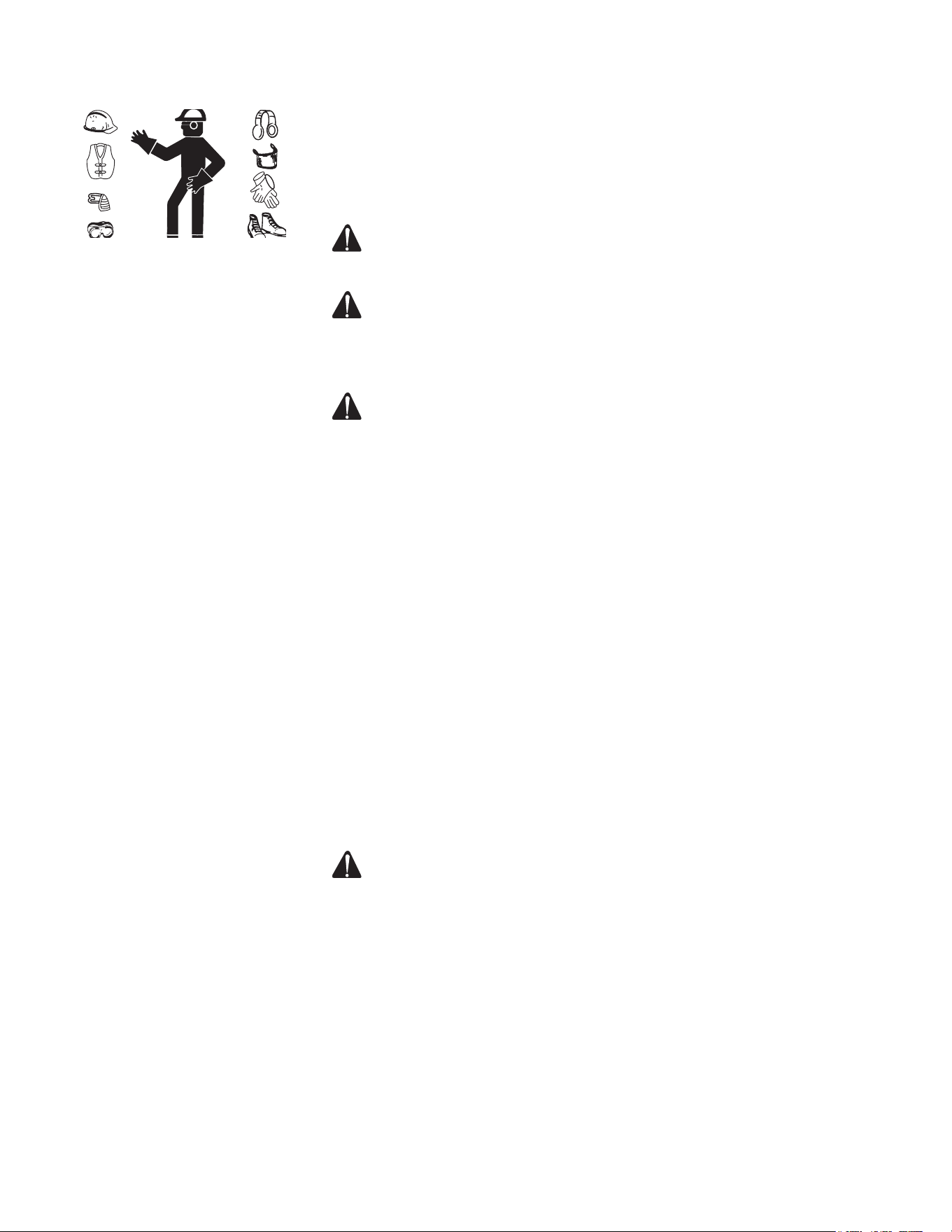
Proper attire is essential to your safety. It is advised to utilize whatever
means necessary to protect eyes, ears, and skin. Additional safety attire
(such as respiratory mask) may be required when using detergent cleaning
agents with this washer.
SET-UP:
DANGER RISK OF EXPLOSION OR FIRE! DO NOT PLACE UNIT
IN AN AREA WHERE FLAMMABLE GAS VAPORS MAY BE
PRESENT. A SPARK COULD CAUSE AN EXPLOSION OR FIRE!
RISK OF UNIT BURSTING! DO NOT STORE/OPERATE UNIT IN
FREEZING ENVIRONMENTS!
1. This unit should only be placed on a level surface to ensure proper lubrication
for the engine and water pump while operating. NEVER spray water directly
on the unit.
WARNING RISK OF ASPHYXIATION! DO NOT OPERATE IN AN
ENCLOSED AREA. USE THIS PRODUCT ONLY IN WELL
VENTILATED AREAS! THE EXHAUST CONTAINS CARBON
MONOXIDE, A POISONOUS, ODORLESS AND INVISIBLE
GAS. BREATHING THIS GAS CAN CAUSE SERIOUS INJURY,
ILLNESS & POSSIBLE DEATH.
2. Do not use unit in an area:
a. with insufcient ventilation.
b. where there is evidence of oil or gas leaks.
c. where ammable gas vapors may be present.
This unit has multiple ignition sources that could cause an explosion or
re.
3. Be certain to block the wheels to prevent the unit from moving while
operating.
4. Do not allow the unit to be exposed to rain, snow or freezing temperatures.
If any part of the unit becomes frozen, excessive pressure may build up in
the unit which could cause it to burst resulting in possible serious injury to
the operator or bystanders.
5. Pump oil level should be checked before each use. Check the oil level
indicator on the pump crankcase. Make certain the oil is in the center of
the oil sight glass. If the level appears to be low, ll with 15W20 detergent
pump oil .
ENGINE/BURNER FUEL TANK:
DANGER RISK OF FIRE! -DO NOT SMOKE WHILE FUELING! -DO
NOT FILL THE FUEL TANK WHILE UNIT IS RUNNING OR
HOT. ALLOW UNIT & ENGINE TO COOL FOR TWO MINUTES
BEFORE REFUELING. -DO NOT FILL FUEL TANK TO POINT
OF OVERFLOWING. ALLOW APPROXIMATELY 1/4" OF TANK
SPACE FOR FUEL EXPANSION.
1. Review "Risk of Explosion or Fire" Warnings, before fueling.
2. Locate the Safety Decals on your unit and heed their warnings.
3. Gasoline Engines: When lling tank, gasoline fuel should be a minimum
of 85 octane. DO NOT MIX OIL WITH GASOLINE. Gasoline fuel should be
purchased in quantities that may be used within 30 days. Use of clean,
fresh lead-free gasoline is recommended. Leaded gasoline may be used
if lead-free is unavailable. DO NOT use gasoline containing methanol or
alcohol.
Burner Fuel: When lling tank, use No. 1 or No 2 fuel oil/diesel or kerosene.
Operator's Manual 13
WARNING RISK OF EXPLOSION OR FIRE! ALWAYS STORE FUEL
AWAY FROM THE WASHER WHILE THE UNIT IS RUNNING
OR HOT.
4. Check the engine oil level before starting the engine. (See Engine
manual.)
5. Refer to the Engine Manual supplied with this unit for proper engine
adjustment procedures.
6. Review the engine manual accompanying this pressure washer for
correct engine start-up and maintenance procedures.
DUAL LANCE ASSEMBLY WITH ADJUSTABLE
PRESSURE:
WARNING RISK OF INJECTION CAUSING SEVERE INJURY! -THE
TRIGGER GUN SHOULD ALWAYS BE LOCKED IN THE OFF
POSITION WHEN NOT IN USE! -NEVER LOOK DIRECTLY AT
THE NOZZLE UNLESS IT IS DISCONNECTED FROM THE
TRIGGER GUN/DUAL LANCE ASSEMBLY!
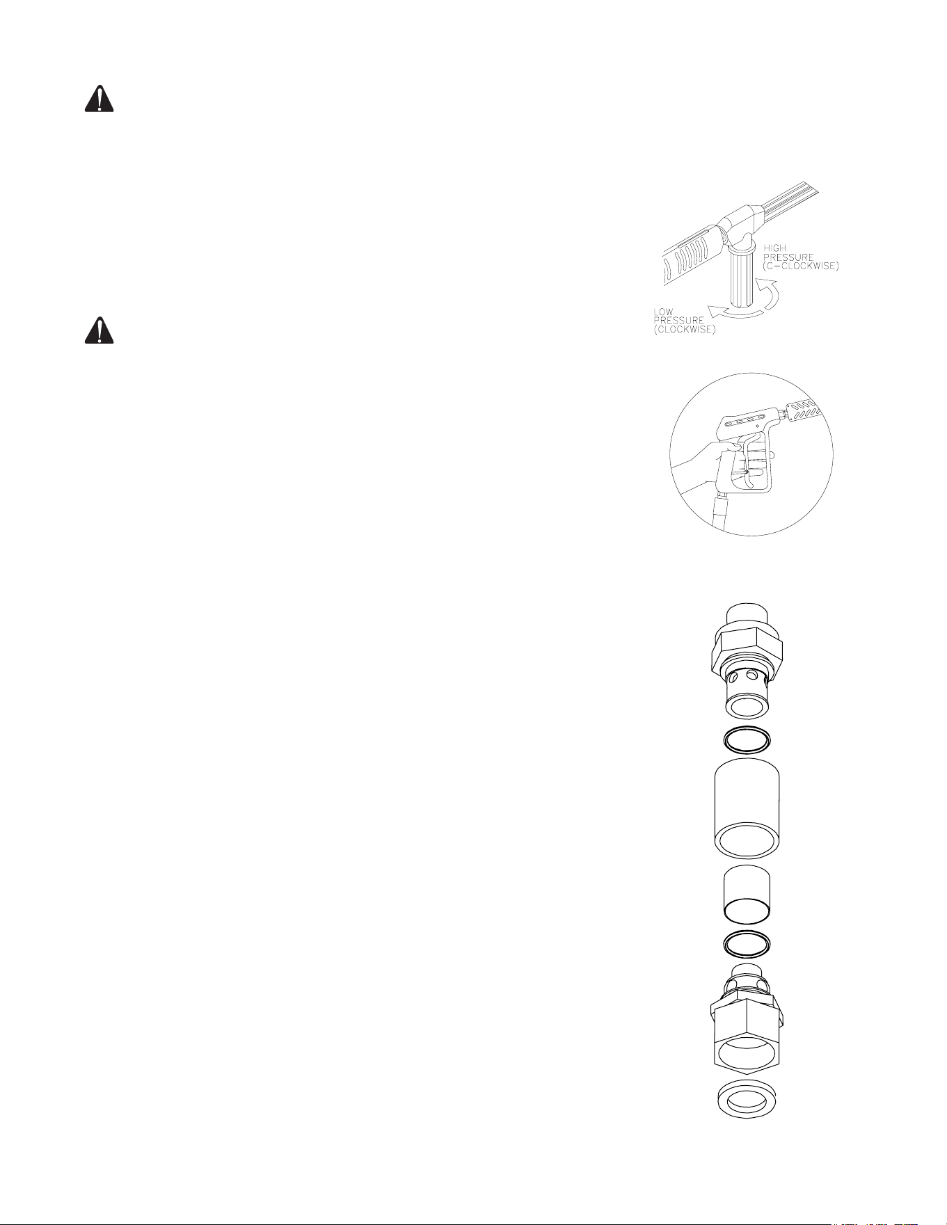
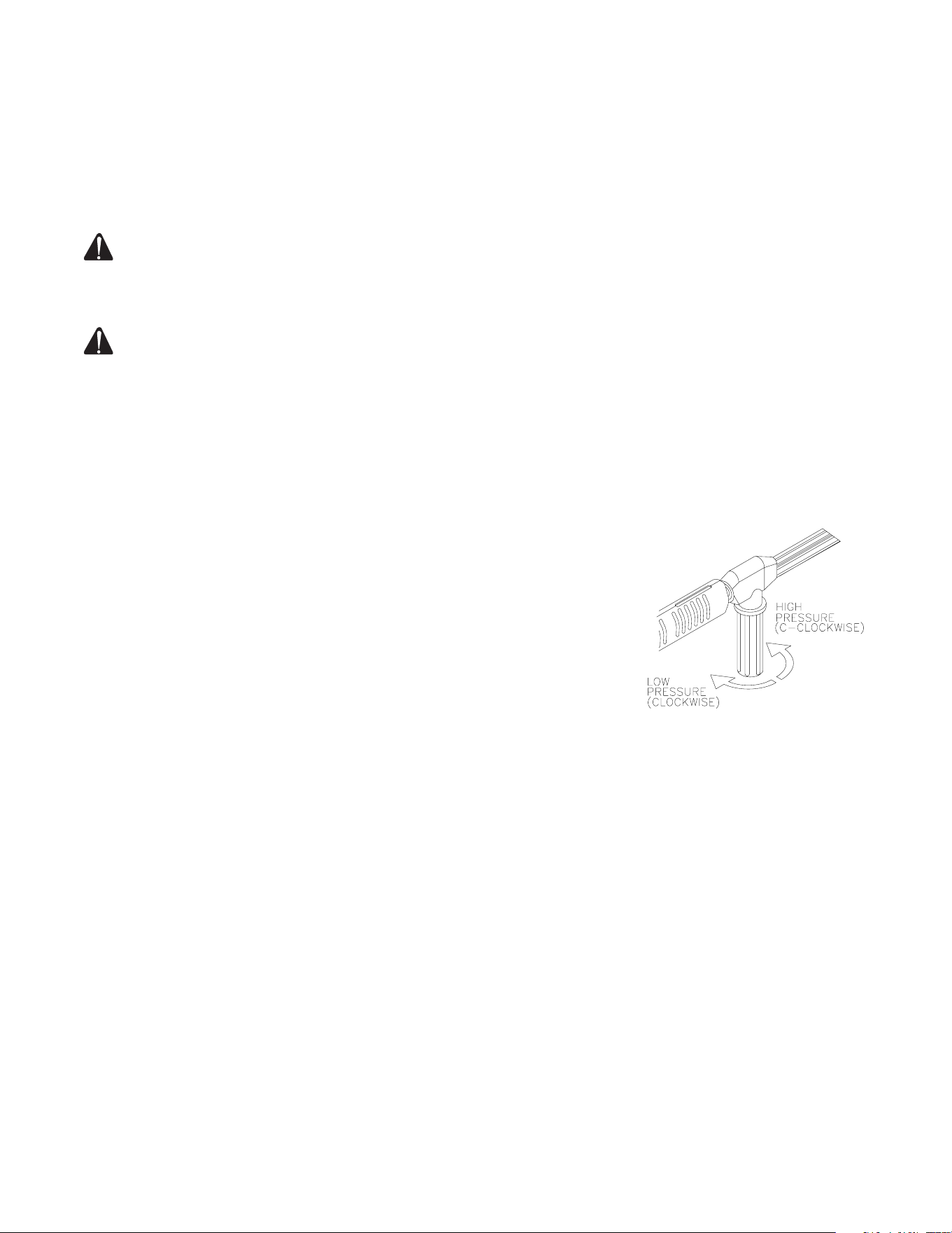
This unit features a Dual Lance Assembly with adjustable pressure which
allows the user to select a high or low pressure "fan" spray. Simply rotate
the adjustable grip on the dual lance to achieve the desired pressure
selection.
1. Selection of high pressure can be achieved by turning the adjustable
grip on the Dual Lance assembly counterclockwise as shown in the
gure below.
2. Selection of low pressure detergent application can be achieved by
turning the adjustable grip on the Dual Lance clockwise as shown in the
gure below. Once the pressure is low enough, the detergent injector
on the pressure washer will draw detergent into the system. A water/
detergent mixture exits from both the spray nozzle and detergent nozzle.
DUAL LANCE CONNECTION:
1. Be certain the trigger gun is locked in the "OFF" position.
2. Connect the dual lance assembly to the trigger gun assembly at this time.
Be certain the connection is securely tightened.
WATER SUPPLY:
1. Select a water supply hose which is a quality grade of garden hose
measuring at least 3/4" ID and no longer than 50 feet.
2 Check the see-through water lter to ensure it is clean and free of any
obstructions. Periodic cleaning of the see-through water lter will help
prevent pump problems. As a lter screen becomes obstructed, it
restricts proper ow of water to the pump. This can result in cavitations
which will cause premature failure of pump packings.
a. Unscrew the garden hose inlet connection from the front of the lter
assembly.
b. Remove the clear plastic cover and clean the lter screen.
3. Connect the hoses:
a. Connect one end of the water supply hose to the water inlet of the
unit.
b. Connect the other end of the hose to your pressurized water supply.
When connecting the water inlet to the water supply mains, local
regulations of your water company must be observed. In some areas,
the unit must not be connected directly to the public drinking water
supply. This is to ensure that there is no feedback of the detergents
into the water supply. (Direct connection is permitted if a back ow
preventer is installed.)
INSTALLATION & PREPARATION
WATER INLET STRAINER

14 Operator's Manual
INSTALLATION & PREPARATION
c. Quick-connect the high pressure discharge hose to the water outlet of
the unit.
d. Connect the other end of the discharge hose to the gun.
4. Follow the incoming water requirements listed below:
a. Water pressure must be a minimum of 25 pounds per square inch (PSI)
and a maximum of 125 PSI. (A typical outdoor faucet will generally
supply this PSI if turned completely "ON".)
b. Incoming GPM must be approximately one gallon more than the
outgoing GPM stated on the pressure washer nameplate. (You can
check GPM by timing how long it takes to ll a 5 gallon container.)
c. Incoming water temperature must not exceed 125°F. Excessive pump
damage may result if the water temperature exceeds this acceptable
level.
5. Never allow the unit to operate without the incoming water line attached
and the water supply completely turned on.
UNLOADER:
CAUTION RISK OF UNIT DAMAGE! DO NOT OVERTIGHTEN THE
UNLOADER. BREAKAGE COULD RESULT IN IMMEDIATE LOSS
OF WATER PRESSURE AND COSTLY REPAIRS.
The pressure has been preset at the factory and should only be adjusted by
a trained Service Representative.
THERMAL RELIEVE VALVE:
To ensure the water temperature does not exceed acceptable levels, never
allow the pressure washer to operate in the bypass mode (with the unit run-
ning and the trigger closed) for more than three minutes.
A thermal relieve valve has been added to this unit to protect the pump. It
may begin to open and release water if the water temperature in the pump
has exceeded
140° F. This will allow fresh, cool water to enter the system, therefore pre-
venting premature failure of pump packings.
PRE-START INSPECTION PROCEDURES:
Before starting the unit, perform the following procedures:
1. Check the oil level in the pump and engine.
2. Inspect the water inlet strainer. Clean or replace if necessary. See "Water
Supply", #2.
3. Check all hose connections to ensure they are securely tightened. See
"Water Supply", #3.
4. Inspect for system water leaks, oil leaks and fuel leaks. If a fuel leak is
found, DO NOT START UNIT! See "Risk of Explosion or Fire". Be sure
that all damaged parts are replaced and that the mechanical problems
are corrected prior to operation of the unit. If you require service, contact
Customer Service.
5. Inspect high pressure hoses for kinking, cuts and leaks. If a cut or leak is
found, DO NOT USE HOSE! Replace hose before starting unit. See "Risk
of Injection". Be sure that all damaged parts are replaced and that the
mechanical problems are corrected prior to operation of the unit. If you
require service, contact Customer Service.

Operator's Manual 15
WARNING
THE FOLLOWING PAGES CONTAIN OPERATING AND MAINTENANCE INSTRUCTIONS.
DO NOT ATTEMPT TO OPERATE THIS PRESSURE WASHER UNTIL YOU HAVE READ
AND UNDERSTOOD ALL SAFETY PRECAUTIONS AND INSTRUCTIONS LISTED IN THIS
MANUAL.
INCORRECT OPERATION OF THIS UNIT CAN CAUSE SERIOUS INJURY!!
DO NOT ALTER OR MODIFY THIS EQUIPMENT IN ANY MANNER!

16 Operator's Manual
OPERATING INSTRUCTIONS
PRIMING THE PUMP:
CAUTION RISK OF UNIT DAMAGE. BE CERTAIN THE HOSE, GUN
& DUAL LANCE ASSY. ARE NOT CONNECTED TO THE UNIT
WHILE PRIMING THE PUMP. PRIMING ALLOWS MINERAL
DEPOSITS TO BE RELEASED FROM THE SYSTEM WHICH
WOULD OBSTRUCT OR DAMAGE THE GUN AND NOZZLE
ASSEMBLY RESULTING IN COSTLY REPAIRS.
It is essential to prime the pump and ush the unit each time the water sup-
ply has been disconnected from the unit OR whenever the unit has set for
any period of time. This unit has a steel coil which, after setting, will cause
the water remaining in the coil from the previous usage to turn brown or
black. This contaminated water must be ushed from the system before
start-up. This procedure should be performed without the high pressure
hose, gun and dual lance assembly installed.
DIRECT FEED: ALL UNITS.
1. Turn on the water supply.
2. Low pressure water will begin owing from the water outlet. This allows
the unit to prime and purge any air from the system. The unit is primed
when water ow is uninterrupted by air.
3. Once the unit is primed, turn off the water supply and connect the high
pressure discharge hose to the water outlet of the unit. (Note: The trigger
gun and dual lance assembly should already be connected to the high
pressure discharge hose at this time.)
4. Turn on the water supply.
START-UP/COLD WATER OPERATION:
1. Refer to the "Safety Precautions" before starting the unit.
2. Locate the Safety Decals on your unit and heed their warnings.
3. Ensure the burner switch is in the "OFF" position.
DANGER RISK OF INJECTION CAUSING SEVERE INJURY! -KEEP
CLEAR OF NOZZLE! NEVER PLACE HAND OR FINGERS IN
FRONT OF NOZZLE! -DO NOT DIRECT DISCHARGE STREAM AT
PEOPLE OR PETS!
4. Pointing the trigger gun in a safe direction, unlock the trigger gun and squeeze
the trigger. Hold the trigger gun open while starting the engine according
to the manufacture's instructions in the engine manual accompanying this
unit.
5. Once the engine has started, ensure the engine throttle is adjusted to full
RPM and perform the following procedures with the trigger gun open:
a. Inspect for system water leaks, oil leaks and fuel leaks. If a
fuel leak is found, TURN UNIT OFF IMMEDIATELY! See "Risk of
Fire". Be sure that all damaged parts are replaced and that the
mechanical problems are corrected prior to operation of the unit. If you
require service, contact Customer Service.
b. Inspect high pressure hoses for kinking, cuts and leaks. If a cut or
leak is found, DO NOT TOUCH HOSE AT LEAK!!! TURN UNIT OFF
IMMEDIATELY! Replace hose before starting the unit. See "Risk of
Injection". Be sure that all damaged parts are replaced and that the
mechanical problems are corrected prior to operation of the unit. If
you require service, contact Customer Service.
6. At this point, the unit is operating as a cold water pressure washer. Trigger
the gun several times and try adjusting the water pressure. NEVER place
hand or ngers in front of the nozzle or look directly into the nozzle! High
pressure water creates a risk of severe injury!
Operator's Manual 17
OPERATING INSTRUCTIONS
7. Do not allow unit to operate in bypass mode (with trigger closed) for more
than three minutes without triggering the gun. Failure to follow this simple
rule can cause premature failure of pump packings, resulting in costly pump
repair.
8. Your pressure washer can deliver high pressure spray and a variety of spray
patterns using cold water. If you wish to use the Hot Water application or
Cleaning with Detergents, see page 17 for the correct procedures.
CAUTION RISK OF DAMAGE. DO NOT ALLOW SPRAY PATTERN
TO REMAIN ON A FIXED AREA FOR AN EXTENDED PERIOD OF
TIME. POSSIBLE DAMAGE MAY OCCUR TO THE AREA.
HOT WATER OPERATION:
WARNING RISK OF BURN! THE WATER TEMPERATURE COULD
BECOME VERY HOT DURING HOT WATER OPERATION. BE
CAUTIOUS WHEN ADJUSTING PRESSURE OR CONTROLLING
THE TRIGGER GUN/DUAL LANCE ASSEMBLY.
1. Follow the steps outlined for "START-UP/COLD WATER OPERATION".
2. Move the Burner Switch to the ON position. On initial start-up, water will
begin turning hot in approximately 20 seconds and will reach maximum
temperature in approximately 2-1/2 minutes, provided the trigger remains
squeezed. The burner will stop ring when the trigger is released.
NOTE: While spraying, it is normal for the burner to fire intermittently.
The high-limit switch will cause combustion to cease when the tem-
perature of the discharged water exceeds the maximum temperature
setting of the switch. Combustion will begin again when the tem-
perature drops below the minimum setting.
At this point, the unit is operating as a hot water pressure washer. Be cer-
tain to be extremely cautious when adjusting the pressure and controlling
the trigger gun/dual lance assembly to avoid the possibility of burns.
CLEANING WITH DETERGENTS UNDER LOW PRESSURE:
NOTE: This feature is designed for use with mild detergents only. Since
the cleaning solution travels through the heat exchanger coil, DO
NOT use corrosives as they will cause extensive damage as well as
pose a considerable safety hazard.
1. Refer to "Risk of Bodily Injury/Detergents" pg. 7. Be certain to wear
protective safety attire as stated on pg. 12.
2. Prepare detergent solution according to label directions. (Never pump acids,
alkalines, abrasive uids or solvents through the unit. Due to the unknown
and often corrosives characteristics of many detergents commonly used
in the pressure washer cleaning industry, it is recommended to use only
manufacturer approved detergents with this unit.)
3. Fully immerse the strainer end of the clear vinyl detergent hose into the
detergent solution.
4. Adjust the amount of detergent desired by locating the adjustment knob at
the end of the clear vinyl hose. Turn the knob completely counterclockwise
to set at maximum siphon rate. Be certain the adjustable grip on the dual
lance is turned completely clockwise for low pressure detergent operation.
NOTE: This injection system is designed to apply detergents under low
pressure only. It will not allow detergent solutions to be introduced
into the system unless the dual lance is set in the low pressure
mode.
5. To apply solution; unlock the trigger gun and squeeze the trigger. In a few
moments a detergent/water mixture will exit the nozzle. Start spraying
the lower portion of the surface being cleaned and move up, using long

18 Operator's Manual
OPERATING INSTRUCTIONS
overlapping strokes. Applying from the bottom up helps avoid streaking.
Allow to soak briey. Avoid working on hot surfaces or in direct sunlight to
minimize the chances of the detergent drying, which may result in damaging
surfaces. Be certain to clean a small section at a time.
6. To rinse; lock the trigger gun in the "OFF" position, rotate the adjustable
grip on the dual lance counterclockwise for high pressure. Unlock the
trigger gun and spray. It will take about 30 seconds to purge all detergent
from the line. For best rinsing results, start at the top and work down.
7. Siphon a gallon of water through the low pressure detergent injection system
after each use. This prevents the possibility of corrosion or detergent
residue causing mechanical problems during the next use.
SHUT-DOWN:
1. Move the burner switch to the OFF position.
2. Squeeze the trigger and discharge the water for a period of three minutes
to cool the heat exchanger and high pressure hose. (Insufcient cool down
period of the high pressure hose will cause excessive wear and eventual
rupturing of the hose.)
3. DO NOT close the choke to stop the engine. Backre or engine damage
may occur.
4. Move the engine On/Off Switch to the "off" position.
5. Close the engine fuel shut-off valve.
6. Turn off the water supply and trigger the gun momentarily to relieve trapped
pressure.
7. Disconnect and store hoses. Store unit in a non-freezing environment.

Operator's Manual 19
SPECIFIC MAINTENANCE:
ENGINE: The engine instruction manual accompanying your unit, lists spe-
cic procedures for maintenance of the engine. Following the engine manu-
facturer's recommendations will extend engine life.
PUMP: Change the pump oil after the rst 50 hours of operation. After
initial change, every 3 months or 250 hour intervals are recommended. If oil
appears dirty or milky, changes may be required in greater frequency. Use
15W20 detergent pump oil
and ll only to the center of the oil sight glass. DO NOT overll.
COUPLERS: There are o-ring seals inside the couplers which will deterio-
rate. To replace, simply install a replacement o-ring to correct the leak. (Ad-
ditional o-rings can be purchased from your dealer.)
NOZZLE: Water ow through the spray nozzle will erode the orice, making
it larger, resulting in a pressure loss. Nozzles should be replaced whenever
pressure is less than 85% of the maximum. The frequency of replacement
will depend upon such variables as mineral content in the water and number
of hours the nozzle is used.
FUEL WATER SEPARATOR: The fuel lter has a built in water separator.
Occasionally the water has to be drained from the separator. Follow the
procedures listed below:
1. Check the collection bowl daily.
2. Ensure the unit is off and place an oil catch basin under the fuel cartridge.
3. Loosen the drain plug to allow the fuel/water contaminants to ow into the
catch basin.
4. Retighten the drain plug when completed.
5. Dispose of drainage according to environmental regulations in your area.
BURNER AIR ADJUSTMENT: The air shutter has been factory preset for
proper operation between sea level and 2000 feet elevation at standard
conditions (60°F ambient water and air temperatures). To assure maximum
combustion efciency at colder temperatures and higher altitudes, it will
be necessary to adjust the air supply to the combustion chamber. A smoke
spot test is recommended during any air shutter adjustment. This will aid in
maximizing the burner efciency and avoid inefcient operation and exces-
sive sooting of the combustion chamber.
1. The machine must be running and the burner ON.
2. Take a smoke spot test to determine if more or less air is required for proper
combustion.
a. If the test is greater than a #3 smoke, turn the shutter arm
counterclockwise to increase the air ow into the combustion chamber.
b. If the test is yellowish in color, turn the shutter arm clockwise to
decrease the air ow into the combustion chamber.
3. Hold onto the air shutter adjusting arm and loosen the locking nut. Move
the shutter in 1/8" increments and retighten the locking nut after each 1/8"
movement.
4. Trigger the gun on and off slowly to make sure there is proper ignition.
Slight or no pufng on the ignition, and a smoke spot test of less than #3
smoke is good.
5. Repeat steps 2 and 3 until step 4 is attained.
LEAKS: Promptly eliminate any leaks found in the pumping system by
removing suspect parts, applying thread sealant to the threads and reinstall-
ing.
NOTE: If using teflon tape, be certain no tape gets inside any plumbing
to prevent the possibility of a plugged spray nozzle.
STORAGE & MAINTENANCE
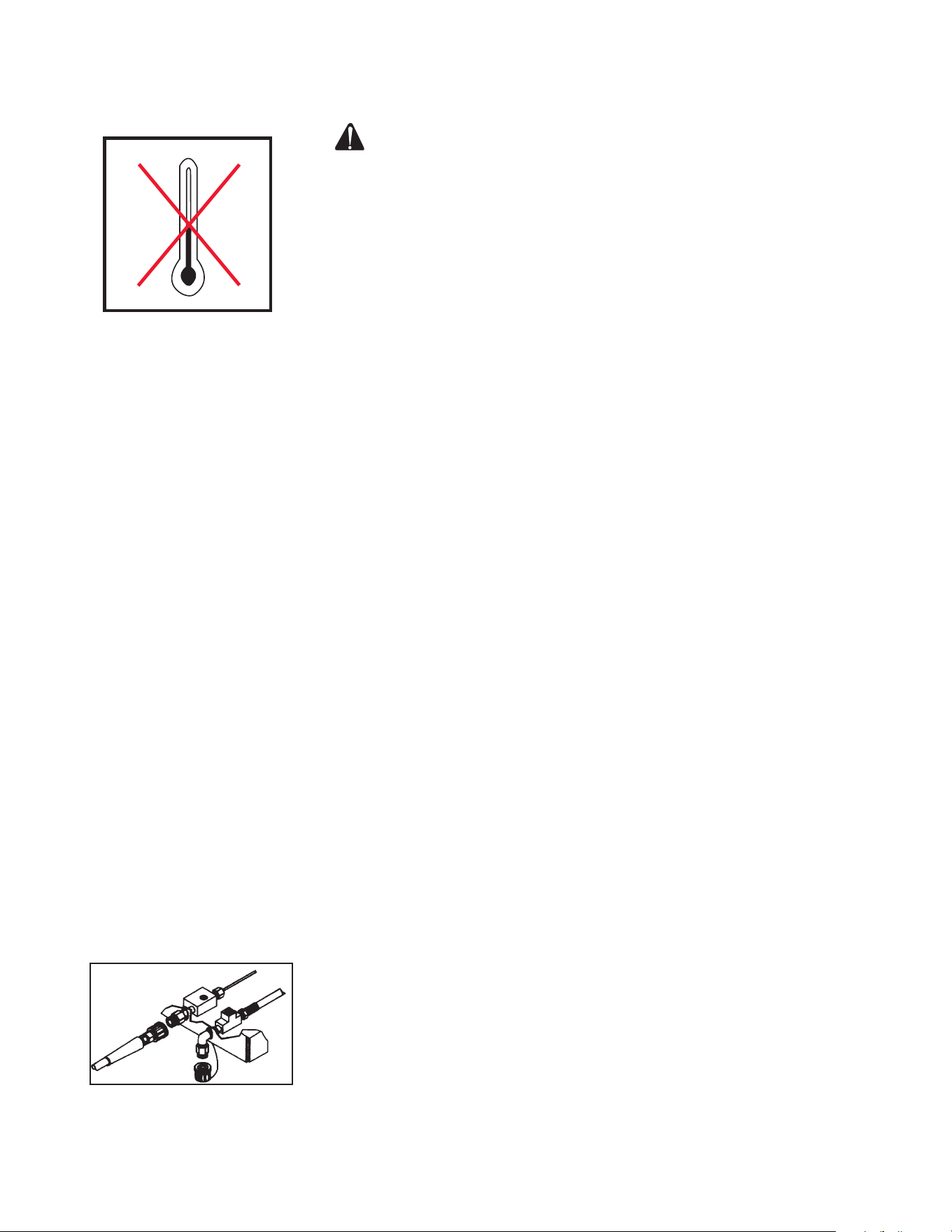
20 Operator's Manual
STORAGE & MAINTENANCE
WINTERIZING:
WARNING RISK OF UNIT BURSTING. DO NOT STORE / OPERATE
UNIT IN A FREEZING ENVIRONMENT!
For storage and transportation purposes in subfreezing ambient tempera-
tures, it will be necessary to winterize this unit. This unit must be protected
to the lowest incurred temperature for the following reasons:
1. If any part of the pumping system becomes frozen; excessive pressure
may build up in the unit which could cause the unit to burst resulting in
possible serious injury to the operator or bystanders.
2. The pumping system in this unit may be permanently damaged if frozen.
FREEZE DAMAGE IS NOT COVERED BY WARRANTY.
If you must store your unit in an area where the temperature may fall below
32°F, you can protect your unit by following the procedure outlined below.
1. Gather the following items:
a. Two 5 gallon containers.
b. One gallon of antifreeze. (Use an environmentally safe antifreeze.)
c. Water supply.
d. Three foot hose, 1/2-3/4 I.D. with a 3/4 inch male garden hose tting.
2. Procedure:
a. To start winterizing, unit must be primed and run according to the
"Start-up/Cold Water Procedures" listed on page 16.
b. After priming and running, shut off the unit and water supply.
c. Relieve system pressure by pointing the trigger gun in a safe direction
and squeezing the trigger until water ow ceases to exit the Dual
Lance Assembly.
d. Lock the trigger gun in the OFF position and remove the Dual Lance
assembly.
e. Remove the water supply hose from the unit and attach the 3 foot hose
securely to the inlet connection.
f. Shut off the detergent injector.
g. Fill one 5 gallon container with water.
h. Holding the 3 foot hose in an upright position, completely ll the hose
with water. Then plug the hose outlet with your thumb or nger. Place
the plugged end into the 5 gallon container of water.
i. Start the unit. Trigger the gun several times until all the air is worked
out of the system (unit is primed). It may be necessary to adjust the
engine RPM down to an idle to aid in priming.
NOTE: Proper winterizing is based on the recommended manufacturer's
instructions listed on the "Protection Chart" shown on the back label
of most antifreeze containers.
j. With the trigger gun held open, siphon enough water out of the 5 gallon
container until there is just enough water left to mix with the antifreeze.
k. Point the trigger gun into the empty container.
l. Trigger the gun until the antifreeze begins to exit the trigger gun.
Release the trigger for 3 seconds, then trigger the gun for 3 seconds.
Continue cycling the trigger gun several times until all the antifreeze
mixture is siphoned from the container.
m. Detach the 3 foot hose from the unit and drain any excess antifreeze
back into the 5 gallon container.
n. Disconnect the hose and trigger gun from the unit and drain any excess
antifreeze back into the 5 gallon container.
o. Store the hose, trigger gun and dual lance assembly with the unit in a
safe area.
COIL DRAIN PLUG
32˚F 0˚C

Operator's Manual 21
STORAGE & MAINTENANCE
p. Store antifreeze solution for next use or dispose of according to state
EPA laws.
3. Optional Procedure:
a. Shut the unit and water supply off.
b. Relieve system pressure by pointing the trigger gun in a safe direction
and squeezing the trigger until water ow ceases to exit the nozzle.
c. Disconnect and drain the hose, trigger gun and dual lance assembly.
d. Remove the hose from the inlet side of the heat exchanger coil.
e. Start the unit and allow it to run until all the water exits the unit. Once
the water has stopped owing from the unit, turn off.
NOTE: When using this procedure, caution should be used as ice chips
can form from drops of water which could cause the unit to burst if
starting before completely thawed.

22 Operator's Manual
SYMPTOM PROBABLE CAUSE REMEDY
Engine will not start. Various engine problems. Refer to the Engine Manual accompanying
your unit.
Unit components are frozen. Allow to thaw. If any part of the unit be-
comes frozen; excessive pressure may
build up in the unit which could cause the
unit to burst resulting in possible serious
injury to the operator or bystanders.
No discharge at nozzle when
trigger mechanism is squeezed
Inadequate water supply. Ensure hose is 3/4" diameter and incoming
water supply is turned on.
Low or uctuating pressure. Kink in water inlet hose. Remove kink.
Kink in high pressure discharge
hose.
Replace kinked high pressure hose.
Water inlet screen obstructed. Remove screen, clean or replace.
Pump sucking air. (Prime elimi-
nated)
Tighten all water intake connections. Elimi-
nate leaks in intake line.
Adjustable Grip on Dual Lance is
not in high pressure mode.
Turn grip counterclockwise to to high pres-
sure.
Obstructed or worn spray nozzle. Remove, clean or replace.
Damaged or obstructed valve assy.
on pump.
Remove, inspect, clean or replace.
Pump packings worn. Replace packings.
Unloader/Bypass valve not operat-
ing correctly.
Repair or replace.
Water is leaking from Heat
DumpValve.
Water temperature is too high. Do not allow unit to operate in bypass
mode (with the trigger gun closed) for more
than three minutes.
Defective valve. Replace.
Oil appears milky or foamy. Water in oil. Change pump oil. Fill to proper level.
Oil leaking from unit. Worn seals or o-rings. Contact Service.
Detergent will not siphon into
Low Pressure Detergent mode.
Detergent strainer is not complete-
ly submerged in detergent solution.
Check, submerge if necessary.
Detergent strainer obstructed. Inspect, clean or replace.
Detergent hose cut, obstructed or
kinked.
Inspect, clean or replace.
Detergent adjusting knob turned to
closed position.
Open adjusting knob. Refer to "Cleaning
with Detergents".
Adjustable grip on dual lance is not
in low pressure mode.
Turn grip clockwise to move to low pres-
sure.
Nozzle assembly is plugged. Clean or replace.
Too many high pressure hose
extensions attached to the water
outlet.
Use one extension maximum.
Ball & Spring in Venturi stuck. Remove, clean or replace.
Water ows back into detergent
container.
Ball & Spring in Venturi reversed,
missing or corroded.
Remove, clean or replace.
Water ows from the nozzle
when the trigger gun is locked in
the "OFF" position.
Trigger gun is malfunctioning. Repair or replace.
TROUBLESHOOTING

Operator's Manual 23
TROUBLESHOOTING
SYMPTOM PROBABLE CAUSE REMEDY
Water is leaking under
heat exchanger coil.
Coil drain plug is not installed. Install.
Safety relief device is relieving caused
by an unloader or pressure switch
problem.
1. Detect and correct unloader or pressure
switch problem
2. Replace safety relief device. NEVER run
unit without safety relief device. Doing so can
cause an explosion!
Burner will not ignite Burner switch is not turned on. Check switch position.
Out of fuel. Refuel.
Trigger gun is closed. Open trigger gun for pressure.
EMF Drive belt loose or broken. Adjust or replace as necessary.
Flexible coupler broken. Replace.
Dirty or clogged fuel lter/water sep. Drain or replace as necessary.
Fuel pump sucking air. Tighten all fuel intake connections. Eliminate
leaks in intake line.
Fuel pump inoperative. Check pressure, replace if needed.
Fuel pickup screen is obstructed. Consult Service.
Dirty or clogged fuel nozzle. Replace fuel nozzle.
Ignition module. Consult Service.
Ignition electrodes damaged or worn. With unit running and trigger gun closed, look
through burner sight glass to ensure there is
sparking across electrodes.
No voltage. Consult Service.
Pressure switch override. Pressure should be over 250 PSI/ 18 Bar to
allow burner to come on.
High limit switch override. Allow unit to cool down before reigniting.
Improper burner air adjustment. Adjust as shown
Fuel solenoid valve failure. Replace.
Burner runs erratically. Water in the fuel oil. Drain fuel lter/water separator,drain fuel tank
and replace with clean fuel.
Dirty fuel lter/water separator. Replace element.
Dirty fuel nozzle. Replace.
Improper air adjustment setting. Adjust as shown
Fuel pickup screen is obstructed. Consult Service.
Fuel pump malfunctioning. Replace.
Burner runs, but will not
heat.
Poor or improper fuel supply. Check fuel to ensure it is correct. Drain tank
and lter if necessary and rell with proper
fuel.
Low fuel pump pressure. Check fuel pump pressure, replace if needed.
Dirty fuel nozzle. Replace.
Improper air adjustment setting. Adjust as shown
Fuel pickup screen is obstructed. Consult Service.
Scale build up in heat exchanger coil. Consult Service.
Burner discharges white
smoke.
Low on fuel. Refuel. If white smoke persists, consult Ser-
vice.
Excessive air supply. Adjust as shown
Burner discharges black
smoke.
Insufcient air supply. Adjust as shown

24 Operator's Manual
MAINTENANCE CHART
PROCEDURE DAILY 3 MONTHS 6 MONTHS 9 MONTHS 12 MONTHS
Check engine oil level X
Change engine oil***** X X X X
Check water pump oil level X
Change water pump oil ** X X X X
Oil leak inspection X
Fuel leak inspection X
Water leak inspection X
Hose inspection X
Water inlet lter inspection X
Check fuel lter/water separator X
Inspect belt X X X X
Replace high pressure nozzle*** X X X X
Replace fuel lter/water separator X
Inspect fuel pump lter* X
Replace fuel nozzle* X
Check burner air adjustment X X X X
Check burner electrodes* X
Test water pressure* X X X X
Test fuel pressure* X X X X
Test water temperature* X X X X
Descale coil**** X
* Must be performed by an authorized service technician.
** The pump oil must be changed after the rst 50 hours of operation and every 250 hours or 3 months, whichever
comes rst.
*** High pressure nozzle should be replaced whenever pressure is less than 85%.
**** Scale build-up will vary with mineral content in the water and amount of usage. Descaling can range from monthly
to yearly maintenance.
***** The engine oil must be changed after the rst 8 hours of operation and every 50 hours or 3 months,
whichever comes rst.

Operator's Manual 25
ACCESSORIES
*Requires 17-0028 1/4" female quick connect.
**Requires 17-0004 3/8" female quick connect.
***PSI and GPM must be specied when ordering.
All Purpose Cleaner, Paint Surface Prep, House & Deck Wash and Heavy Duty Degreaser are specially formulated deter-
gents for use with all HSP pressure washers and are packaged in One (1), Five (5) and Fifty-ve (55) gallon containers.
15-0006 SUPPLY HOSE 3/4” XXXX
50-0136 HOSE REEL 13” (HOLDS 100’ OF HOSE) XXXX
50-0137 HOSE REEL 16” (HOLDS 200’ OF HOSE) XXXX
AW-0050-0138 BRACKET FOR HOSE REEL (UNIVERSAL) XXXX
50-0140 BRACKET FOR HOSE REEL (22” BAR) X
852-0138 JUMPER HOSE FOR HOSE REEL (4000 PSI) XXX
852-0139 JUMPER HOSE FOR HOSE REEL (4000 PSI) X
AW-3000-0035 SANDBLASTER NOZZLE* XXX
AW-3000-0004 SANDBLASTER NOZZLE *X
AW-4085-0016 PUMP OIL XXXX
AW-7004-0045 ROTATING NOZZLE (.045 / 5000 max) *XXXX
AW-7003-1500 ROTATING BRUSH *XXXX
AW-7018-1200 EXTENSION WAND 12’ ** (3000 PSI) XX
AW-7018-1800 EXTENSION WAND 18’ ** (3000 PSI) XX
AW-7018-2400 EXTENSON WAND 24’ ** (3000 PSI) XX
AW-7020-8003 ROTARY SURFACE CLEANER** (20” 4000 PSI) XXXX
AW-7020-8001 ROTARY SURFACE CLEANER** (28” 4000 PSI) XXXX
AW-7025-8000 25” POWER BROOM (5 - 80° NOZZLES)*/*** XXXX
AW-7035-8000 35” POWER BROOM (7 - 80° NOZZLES)*/*** XXXX
HSP-2503
HSP-3004
HSP-3504
HSP-4004

26 Operator's Manual
STATEMENT OF WARRANTY
The manufacturer warrants all parts, (except those referred to below), of your new HSP-
Series Pressure Washer to be free from defects in materials and workmanship during the
following periods:
For Lifetime (Limited) against freezing and cracking:
Pump Manifold
For Seven (7) Years from the date of original purchase:
High Pressure Pump
For Three (3) Years from the date of original purchase:
Heat Exchanger Coil
For One (1) Year from the date of original purchase:
High Pressure Pump
Frame Pulley
Guard or Shields EMF System
Plumbing
For Ninety (90) days from the date of original purchase:
Control Switches Safety Switches
Regulating Valve Fuel Pump
Unloader Valve Electrodes
Fuel Solenoid Safety Relief Valve
High Limit Thermostat Temperature Switch
Pressure Switch
For Thirty (30) day from the date of original purchase:
High Pressure Hose Trigger Gun
Strainers / Filters Wand
Defective parts not subject to normal wear and tear will be repaired or replaced at our option
during the warranty period. In any event, reimbursement is limited to the purchase price paid.
EXCLUSIONS
1. Engine is covered under separate warranty by its respective manufacturer and is subject
to the terms set forth therein.
2. Normal wear parts:
Pump Packings Spray Nozzles
Pump Valves Screw Connectors/Quick Couplings
Detergent Valves Fuel Filters
O-rings Belts
3. This warranty does not cover parts damaged due to normal wear, misapplication,
misuse, operation at other than recommended speeds, pressures or temperature.
Parts damaged or worn because of the use of caustic liquids or by operation in
abrasive or corrosive environments or under conditions causing pump cavitation
are not warranted. Failure to follow recommended operating and maintenance
procedures also voids warranty.
4. The use of other than genuine manufactured repair parts will void warranty. Parts
returned, prepaid to our factory or to an Authorized Service Center will be inspected
and replaced free of charge if found to be defective and subject to warranty. There
are no warranties which extend beyond the description of the face hereof. Under
no circumstances shall the manufacturer bear any responsibility for loss of use of
the unit, loss of time or rental, inconvenience, commercial loss or consequential
damages.

Operator's Manual 27
NOTES

28 Manual del operador
ADVERTENCIA: Este producto puede
exponerlo a productos químicos, incluido el
plomo, que el Estado de California conoce a
causar cáncer y defectos congénitos u otros
daños reproductivos. Para obtener más
información, visite www.P65Warnings.ca.gov
ADVERTENCIA
ADVERTENCIA: Este producto puede expo-
nerle a químicos incluyendo carbon monoxide,
que es conocido por el Estado de California
como causante de defectos de nacimiento u
otros daños reproductivos. Para mayor
información, visite www.P65Warnings.ca.gov.
ADVERTENCIA
TABLA DE CONTENIDO
INTRODUCCIÓN ...........................................................................................................29
RIESGO DE EXPLOSIÓN O INCENDIO ................................................................................................... 30
RIESGO DE ASFIXIA ................................................................................................................................30
RIESGO DE INYECCIÓN O LESIÓN POR CORTADURA SEVERA .........................................................31
RIESGO DE ELECTROCUCIÓN O CHOQUE ELÉCTRICO ......................................................................31
RIESGO DE QUEMADURAS ....................................................................................................................31
RIESGO DE EXPLOSIÓN .........................................................................................................................32
RIESGO POR PARTES EN MOVIMIENTO ...............................................................................................32
RIESGO DE LESIONES............................................................................................................................32
CARACTERÍSTICAS BASE PEQUEÑO ........................................................................ 34
LISTA DE COMPONENTES ..........................................................................................35
CARACTERÍSTICAS BASE GRANDE ..........................................................................36
LISTA DE COMPONENTES ..........................................................................................37
INSTALACIÓN Y PREPARACIÓN .................................................................................38
VESTIMENTA: ..........................................................................................................................................38
PREPARACIÓN INICIAL: ..........................................................................................................................38
TANQUES DE COMBUSTIBLE DEL MOTOR/QUEMADOR: ...................................................................38
CONJUNTO DE VARILLA DOBLE CON PRESIÓN AJUSTABLE: ............................................................39
CONEXIÓN DE VARILLA DOBLE: ............................................................................................................39
SUMINISTRO DE AGUA: .........................................................................................................................39
DESCARGADOR: .....................................................................................................................................40
VÁLVULA PARA DISIPAR CALOR: ........................................................................................................... 40
PROCEDIMIENTOS DE INSPECCIÓN ANTES DEL ENCENDIDO: .........................................................40
INSTRUCCIONES DE OPERACIÓN .............................................................................43
CEBADO DE LA BOMBA: ........................................................................................................................ 43
ARRANQUE/OPERACIÓN CON AGUA FRÍA: .........................................................................................43
OPERACIÓN CON AGUA CALIENTE: .....................................................................................................44
LIMPIEZA CON DETERGENTES BAJA PRESIÓN: .................................................................................. 44
APAGADO ................................................................................................................................................ 45
ALMACENAJE Y MANTENIMIENTO ...........................................................................46
MANTENIMIENTO ESPECIFICO:.............................................................................................................46
PREPARACION PARA EL INVIERNO: ...................................................................................................... 47
LOCALIZACION DE FALLAS ........................................................................................ 49
TABLA DE MANTENIMIENTO ......................................................................................52
ACCESORIOS ...............................................................................................................53
DECLARACIÓN DE GARANTÍA ...................................................................................54
Manual del operador 29
Felicitaciones por haber adquirido su nueva lavadora a presión de agua caliente, con el Sistema de Encendido
Electromagnético (EMF) patente. Puede estar seguro de que su lavadora a presión de agua caliente fue construida y
diseñada pensando en la calidad y la ecacia de funcionamiento. Cada componente ha sido probado rigurosamente
para asegurar el nivel más alto de conabilidad.
Este manual del operador fue preparado para su benecio. Si lee y sigue los sencillos pasos de seguridad, insta-
lación, operación y mantenimiento, así como de diagnóstico y solución de fallas que se describen en este manual,
su nueva lavadora a presión de agua caliente le ofrecerá muchos años de operación sin problemas. El contenido
de este manual se basa en la información más reciente del producto, disponible al momento de la publicación. El
fabricante se reserva el derecho de hacer cambios de precio, color, materiales, equipo, especicaciones o modelos
en cualquier momento sin previo aviso.
INTRODUCCIÓN
Una vez que haya sacado la unidad de su caja, anote inmediatamente el número de serie en el espacio proporcio-
nado a continuación.
Número de serie: _____________________
Debe inspeccionar el equipo para determinar si hay señas de daño evidente u oculto ocurrido durante la trans-
portación. Si se encuentra algún daño, presente una queja con la compañía de transportación inmediatamente.
Asegúrese de que todas las partes dañadas sean reemplazadas y que los problemas mecánicos y eléctricos sean
corregidos antes de operar la unidad. Si requiere de servicio, llame a la ocina de servicio a clientes.
Por favor, prepare la siguiente información cada vez que efectúe una llamada de servicio:
1. Número de modelo
2. Número de serie
3. Fecha y lugar de compra
¡IMPORTANTE!
Estos párrafos están rodeados por un “Cuadro de Aviso de Seguridad”. Este cuadro se usa para especicar y
enfatizar las advertencias de seguridad que se deberán cumplir al operar esta lavadora a presión. Junto con las
Advertencias de Seguridad se encuentran “palabras clave” que designan el grado o nivel de riesgo. Las “pal-
abras clave” usadas en este manual son las siguientes:
PELIGRO: INDICA UNA SITUACIÓN INMINENTEMENTE PELIGROSA QUE, DE NO EVITARSE, CAUSARÁ
LESIONES GRAVES O FATALES.
ADVERTENCIA: INDICA UNA SITUACIÓN POTENCIALMENTE PELIGROSA QUE, DE NO EVITARSE,
PODRÍA CAUSAR LESIONES GRAVES O FATALES.
PRECAUCIÓN: INDICA UNA SITUACIÓN POTENCIALMENTE PELIGROSA QUE, DE NO EVITARSE,
PODRÍA CAUSAR UNA LESIÓN MENOR O MODERADA.
Los símbolos a la izquierda de este párrafo son “símbolos de aviso de seguridad”. Estos símbolos se usan para
señalar puntos o procedimientos que podrían ser peligrosos para usted o para otras personas que usen este
equipo.
Siempre proporcione una copia de este manual a quien use este equipo, lea todas las instrucciones antes de
operar esta lavadora a presión y especialmente señale las “advertencias de seguridad” para prevenir posibles
lesiones al operador. ¡Sólo los operadores que estén capacitados deben usar este producto!
ADVERTENCIAS DE SEGURIDAD
30 Manual del operador
RIESGO DE EXPLOSIÓN O INCENDIO
Pueden ocurrir lesiones graves o fatales ocasionadas por chispas normales
en las fuentes de ignición múltiples o en el escape del motor y del quema-
dor.
Siempre opere la lavadora en una área bien ventilada libre de vapores in-
amables, polvo combustible y gases o materiales combustibles.
No almacene la lavadora a presión cerca de una llama abierta o equipo
como hornos, calefactores, calentadores de agua, etc., que usen una llama
piloto o dispositivo de encendido por chispa.
¡No use esta lavadora a presión para atomizar material inamable!
Pueden ocurrir lesiones graves o fatales como consecuencia de un proced-
imiento inadecuado al reabastecer de combustible.
No fume mientras llene los tanques de combustible.
Nunca llene los tanques de combustible mientras el motor aún esté en
marcha o esté caliente. Permita que el motor se enfríe dos minutos antes de
volver a cargar combustible.
No llene los tanques de combustible en interiores o en una área con poca
ventilación.
Siempre vierta el combustible lentamente para evitar la posibilidad de un
derrame, lo cual podría provocar un incendio.
Tanque de combustible del motor:
Si se usa un motor de gasolina, llene únicamente con gasolina. No use die-
sel ni petróleo o aceite combustible.
Tanque de combustible del quemador (negro):
Al llenar el tanque de combustible del quemador, use aceite de combustible
diesel o queroseno No.1 ó No.2. No use gasolina.
No opere la unidad si se derrama gasolina o combustible de diesel. Con
un paño, limpie completamente la lavadora a presión y aléjela del derrame.
Evite crear cualquier ignición hasta que el combustible de gasolina o diesel
se haya evaporado.
Pueden ocurrir lesiones graves o fatales como consecuencia de un incendio
al ras de tierra ocasionado por una chispa del silenciador.
Se debe agregar un parachispas al silenciador de este motor si se va a usar
sobre terrenos sin construir de bosques, o cubiertos de maleza o pasto. El
parachispas deberá ser mantenido en buen funcionamiento por el operador.
En el estado de California, lo anterior es obligatorio por ley. (Sección 4442
del Código de Recursos Públicos de California). Otros estados quizá tengan
leyes similares. En terrenos federales se aplican las leyes federales.
Pueden ocurrir lesiones graves o fatales si no se mantienen correctamente
los dispositivos de seguridad del sistema.
Esta lavadora a presión tiene un dispositivos de seguridad aparato que
nunca deben ser alterados, modicados, extraídos o desconectados. Si falla
el dispositivo, reemplácelo inmediatamente con un repuesto genuino del
fabricante.
RIESGO DE ASFIXIA
Pueden sufrirse lesiones graves o fatales como consecuencia de la inha-
lación de gases del escape del motor/quemador o vapores peligrosos. El
gas que emana del escape de este producto contiene substancias quími-
cas identicadas por el Estado de California como agentes que provocan
cáncer, defectos de nacimiento o daños reproductivos.
ADVERTENCIAS DE SEGURIDAD
Manual del operador 31
Esta lavadora a presión fue diseñada para uso externo únicamente. Nunca
opere esta lavadora a presión en una área cerrada. Siempre asegúrese de
que exista ventilación adecuada (aire externo fresco) para la respiración y la
combustión. Esto impedirá la acumulación de gases peligrosos de monóxi-
do de carbono. Tenga cuidado en las áreas de poca ventilación, o áreas con
ventiladores de extracción que pueden provocar un intercambio deciente
de aire.
Obedezca todas las instrucciones proporcionadas con los materiales que
está rociando. Quizá sea necesario usar un respirador cuando se trabaje
con ciertos materiales. No use esta lavadora a presión para distribuir deter-
gentes peligrosos.
RIESGO DE INYECCIÓN O LESIÓN POR CORTADURA
SEVERA
Pueden sufrirse lesiones graves o fatales como consecuencia de la atom-
ización a alta presión con penetración en la piel.
¡Manténgase completamente alejado de la boquilla y el atomizador! Nunca
coloque la mano, los dedos o el cuerpo directamente sobre la boquilla de
rocío.
Nunca apunte el atomizador alta presión hacia usted mismo o hacia otra
persona.
Siempre mantenga el área de trabajo despejada de personas.
NO PERMITA que algún niño opere esta unidad.
¡BUSQUE ATENCIÓN MÉDICA DE EMERGENCIA si parece que el rocío ha
penetrado la piel! ¡No lo trate como una simple cortadura!
Debe inspeccionar diariamente las mangueras de alta presión y las líneas
de combustible para buscar señales de desgaste. Si hay evidencia de falla,
reemplace inmediatamente todas las mangueras y líneas de combustible
sospechosas para prevenir la posibilidad de lesiones por el rocío a alta
presión. Si una manguera o conexión tiene alguna fuga, NO COLOQUE SU
MANO DIRECTAMENTE SOBRE LA FUGA.
NUNCA opere la pistola con el gatillo jado en la posición abierta. Para pre-
venir una descarga accidental, la pistola debe tener bien trabado el seguro
del gatillo cuando no se encuentre en uso.
Antes de retirar la boquilla de rocío o dar servicio a la unidad, apague la uni-
dad y tire del gatillo de la pistola para liberar la presión. (Aun cuando apague
la unidad, todavía quedará agua a alta presión en la bomba, la manguera y
la pistola hasta que la libere jalando el gatillo de la pistola.)
RIESGO DE ELECTROCUCIÓN O CHOQUE ELÉCTRICO
Pueden sufrirse lesiones graves o fatales debido al contacto con la electric-
idad.
¡NO dirija el rocío hacia instalaciones eléctricas de ninguna clase! Esto
incluye tomas eléctricas, lámparas, cajas de fusibles, transformadores, la
unidad misma, etc.
NO permita que los componentes de metal de la lavadora a presión entren
en contacto con componentes eléctricos cargados.
RIESGO DE QUEMADURAS
Pueden producirse lesiones graves si se toca el motor de gasolina, el silen-
ciador o el intercambiador de calor. Estas áreas pueden permanecer calien-
tes por algún tiempo después de que se ha apagado la lavadora a presión.
Nunca permita que ninguna parte de su cuerpo haga contacto con el motor
de gasolina, el silenciador o el intercambiador de calor.
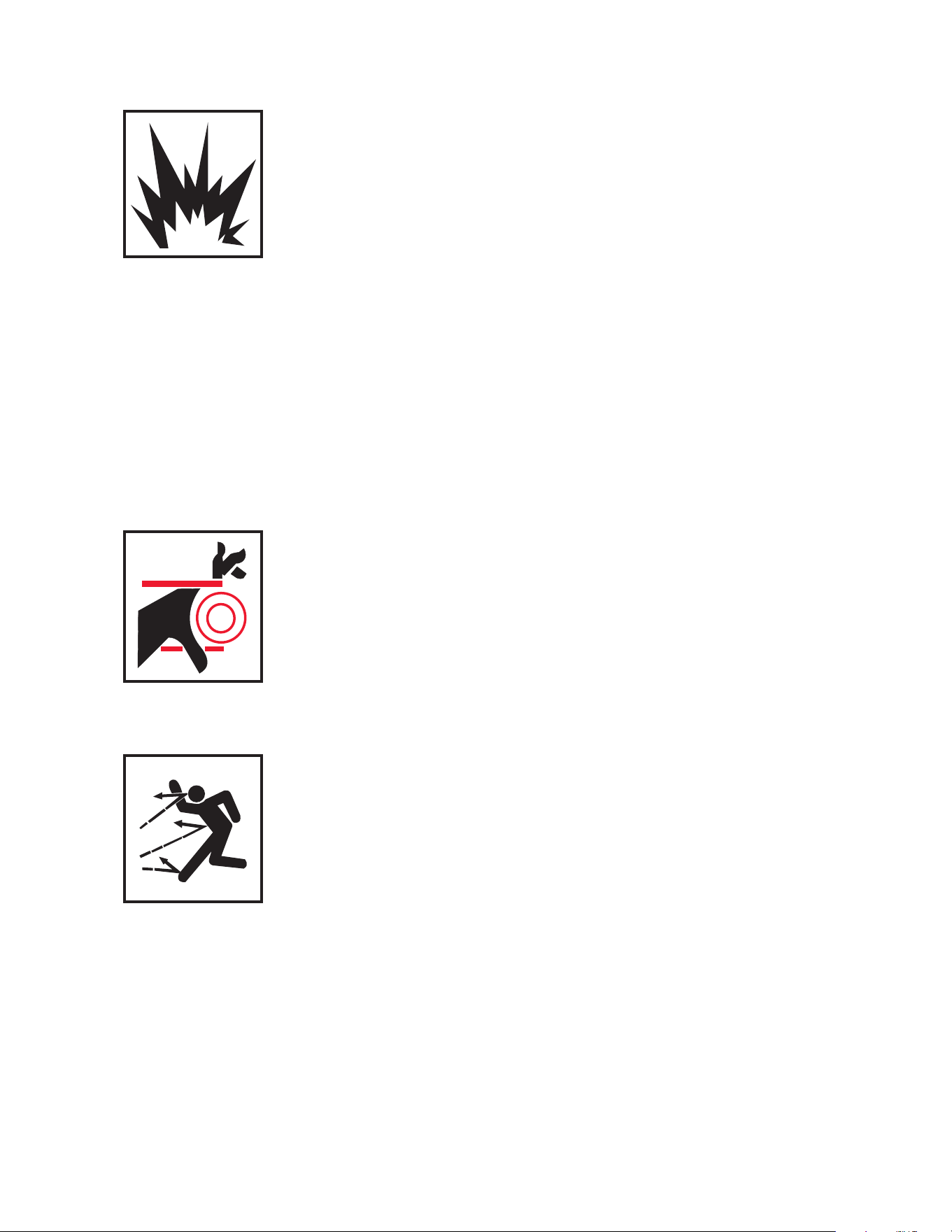
ADVERTENCIAS DE SEGURIDAD
32 Manual del operador
RIESGO DE EXPLOSIÓN
Pueden producirse lesiones graves debido al mal funcionamiento de la
lavadora a presión o la explosión de accesorios si se usan componentes,
aditamentos o accesorios que no correspondan al sistema.
Nunca haga ajustes a las presiones conguradas en la fábrica.
Nunca exceda la máxima graduación de presión de los accesorios permitida
por el fabricante.
No permita que alguna de las mangueras haga contacto con el silenciador
del motor, el motor de gasolina o el intercambiador de calor para prevenir
la posibilidad de explosión. No arrastre las mangueras sobre supercies
abrasivas como el cemento.
Pueden producirse lesiones graves o fatales si se intenta arrancar la lava-
dora a presión cuando esté congelada la bomba.
Solo use las partes de reparación para su lavadora a presión recomendadas
por el fabricante.
En temperaturas de congelación, la unidad siempre deberá permanecer lo
sucientemente caliente como para asegurar que no haya formación de
hielo en la bomba. No arranque la lavadora a presión si ha sido transportada
en un vehículo abierto o de calefacción deciente, sin primero permitir que
la bomba se descongele.
RIESGO POR PARTES EN MOVIMIENTO
El operador puede sufrir de lesiones graves si hace contacto con las partes
en movimiento de la lavadora a presión.
Antes de hacer cualquier ajuste, asegúrese de que el motor esté apagado
y que el cable o los cables de ignición estén separados de las bujías de
ignición. Al voltear la máquina manualmente durante el ajuste o la limpieza
puede arrancar el motor y junto con él, la máquina.
No opere la unidad sin que todas las cubiertas protectoras se encuentren en
su lugar.
RIESGO DE LESIONES
Pueden ocurrir lesiones graves o fatales si los detergentes entran en con-
tacto con la piel.
¡BUSQUE ATENCIÓN MÉDICA DE EMERGENCIA si está usando agentes de
limpieza y siente que el rocío ha penetrado la piel! ¡NO LO TRATE COMO
UNA SIMPLE CORTADURA! Lea la hoja de datos de seguridad del mate-
rial (MSDS) proporcionada con su detergente para estar preparado y poder
informar a su médico exactamente qué tipo de detergentes estaba usando.
Pueden ocurrir lesiones graves provocadas por partículas sueltas proyecta-
das a gran velocidad a través la pistola atomizadora.
Nunca use solventes o detergentes altamente corrosivos o limpiadores de
tipo ácido con esta lavadora a presión.
Se aconseja usar equipo protector como trajes de goma, guantes y respira-
dores, especialmente cuando se usen detergentes limpiadores.
¡Mantenga todos los detergentes fuera del alcance de los niños!
Pueden ocurrir lesiones si el operador pierde el equilibrio causado por el
impulso del agua que está atravesando la boquilla de rocío.
SIEMPRE use gafas protectoras cuando opere la unidad para proteger sus
ojos contra residuos y detergentes lanzados al aire.
NO DIRIJA el atomizador hacia materiales frágiles tales como vidrio, ya que
podría ocasionar su ruptura.

ADVERTENCIAS DE SEGURIDAD
Manual del operador 33
Manténgase alerta — vigile lo que esté haciendo. No opere la unidad cu-
ando esté fatigado o bajo la inuencia de alcohol o drogas.
NUNCA apriete el gatillo a menos de que esté rmemente parado.
Pueden ocurrir lesiones provocadas por la lavadora a presión.
NO se estire demasiado ni se pare sobre un soporte inestable.
Las supercies mojadas pueden estar resbaladizas, use equipo protector y
mantenga un punto de apoyo y buen equilibrio en todo momento.
NUNCA accione la pistola mientras se encuentre en una escalera o sobre un
techo.
SIEMPRE sostenga rmemente el conjunto de pistola/varilla cuando ar-
ranque y opere la unidad. No hacerlo podría provocar que la varilla se caiga
y se azote peligrosamente.
Sepa como detener la lavadora a presión y aliviar las presiones rápidam-
ente. Familiarícese por completo con estos controles.
NO permita que la unidad presurizada permanezca sola. Apague la lavadora
de presión y libere la presión antes de irse.
NO OPERE la unidad si detecta fugas de combustible, aceite o agua de la
máquina. NO reanude la operación hasta que la unidad haya sido inspeccio-
nada y reparada por un técnico capacitado para el servicio.
NUNCA accione la unidad con el regulador desconectado ni opere a veloci-
dades excesivas.
Coloque la unidad sobre una supercie limpia, seca y plana para darle
servicio. Antes de dar mantenimiento a la unidad, apáguela, alivie la presión
de agua apretando el gatillo de la pistola, y permita que la unidad se enfríe.
Realice el mantenimiento en un área limpia, seca y plana. Donde sea nece-
sario, bloquee las ruedas para prevenir el movimiento de la unidad.
No mueva la unidad tirando de la manguera.
¡CONSERVE ESTAS INSTRUCCIONES!
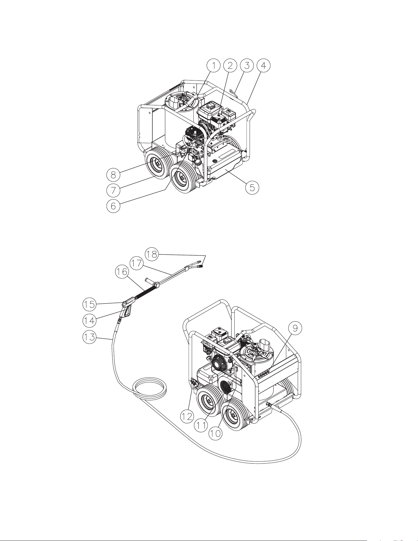
34 Manual del operador
CARACTERÍSTICAS BASE PEQUEÑO
HSP SMALL FEATURES 022713 CH

Manual del operador 35
1. Gancho Levantar
2. Deposito del Gasolina Motor
3. Soporte de Varilla
4. Rollo Resguardo
5. Deposito del Combustible Quemada
6. Bomba del Presion Alta
7. Ruedas Neumaticos
8. Separador de agua y combustible
9. Soporte para boquilla
10. Varillas de Quemadura
11. Quemador aire el reglamento
12. Freno
13. Manguera de descarga de alta presión
14. Gatillo Cerraduro de Seguridad
15. Conjunto del la Pistola
16. Lanza Aislante
17. Lanza de Dual Presión Reguable
18. Boquillas
LISTA DE COMPONENTES
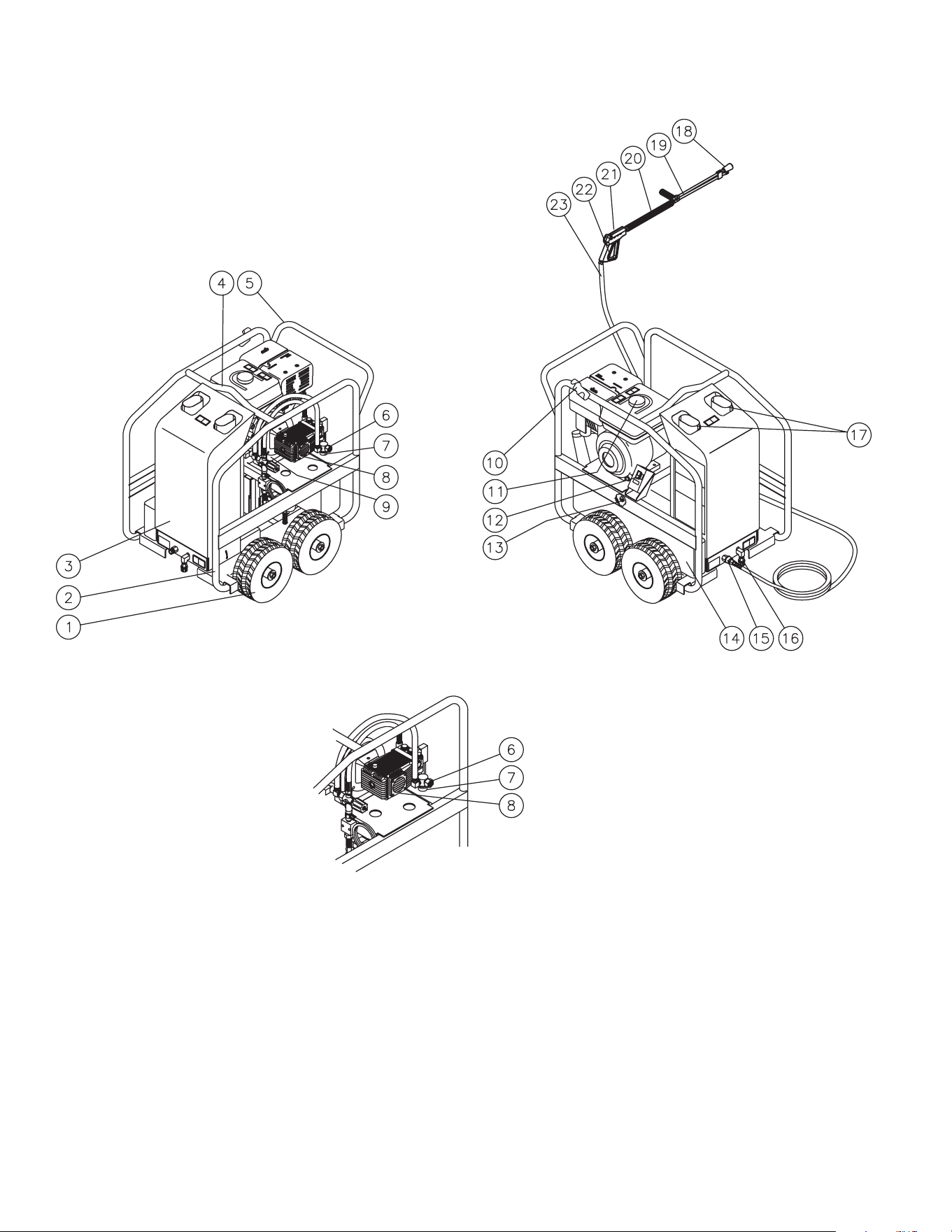
36 Manual del operador
CARACTERÍSTICAS BASE GRANDE
OMHSP044-012612-CH

Manual del operador 37
LISTA DE COMPONENTES
1. Ruedas Neumaticos
2. Rollo Resguardo
3. Tapa Protector
4. Gancho Levantar
5. Mango Convenient de Empujon / Tirón
6. Entrada de Agua
7. Tamiz de Agua
8. Bomba del Presion Alta
9. Guarda Correa
10. Soporte de Varilla
11. Deposito del Gasolina Motor
12. Varillas de Quemadura
13. Depostible del Aire Regulable
14. Deposito del Combustible Quemada
15. Salida de Alta Presión
16. Tapon de Rollo Desaquadero
17. Quemadura Exhosto
18. Boquillas
19. Lanza de Dual Presión Reguable
20. Lanza Aislante
21. Conjunto del la Pistola
22. Gatillo Cerraduro de Seguridad
23. Manguera de descarga de alta presión
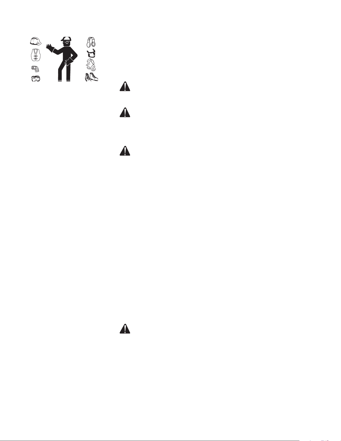
38 Manual del operador
VESTIMENTA:
1. Es importante usar ropa apropiada para su seguridad. Se aconseja usar
cualquier medio necesario para proteger los ojos, las orejas y la piel.
Posiblemente requiera equipo adicional de seguridad (como un respirador)
cuando use detergentes limpiadores con esta lavadora.
PREPARACIÓN INICIAL:
PELIGRO ¡RIESGO DE EXPLOSIÓN O INCENDIO! NO COLOQUE
LA UNIDAD EN UNA ÁREA DONDE PUEDAN EXISTIR VAPORES
INFLAMABLES. UNA CHISPA PODRÍA PROVOCAR UNA
EXPLOSIÓN O UN INCENDIO.
¡RIESGO DE LA EXPLOSIÓN DE LA NIDAD! ¡NO ALMACENE/OPERE
LA UNIDAD EN AMBIENTES DE CONGELACIÓN!
1. Este aparato debe quedar siempre colocado sobre una supercie nivelada
para asegurar la lubricación apropiada del motor y de la bomba de agua
durante la operación. NUNCA rocíe agua directamente a la unidad.
ADVERTENCIA ¡RIESGO DE ASFIXIA! ¡USE ESTE PRODUCTO
ÚNICAMENTE EN ÁREAS BIEN VENTILADAS! NO OPERE EN
UNA ÁREA ENCERRADA. EL ESCAPE EXPULSA MONÓXIDO
DE CARBONO, UN GAS VENENOSO INODORO E INVISIBLE.
RESPIRAR ESTE GAS PUEDE PROVOCAR LESIONES GRAVES,
ENFERMEDAD O POSIBLE MUERTE.
2. No use esta unidad en un área:
a. sin suciente ventilación
b. donde haya evidencia de fugas de aceite, gas o combustible.
c. donde pueda haber presencia de vapores inamables.
Esta unidad tiene varias fuentes de ignición que podrían provocar una
explosión o incendio.
3. Si tiene ruedas, asegúrese de bloquearlas para evitar que la unidad se
mueva durante la operación.
4. No permita que la unidad quede expuesta a la lluvia, la nieve o temperaturas
de congelación. Si alguna parte de la unidad se congela, es posible que
se acumule una presión excesiva en la unidad, lo cual podría provocar su
estallido y consecuentemente posibles lesiones al operador o las personas
alrededor.
5. Debe revisarse el nivel de aceite de la bomba debe revisarse antes de
cada aplicación. Revise el indicador de nivel de aceite en el cárter de la
bomba. Asegúrese de que el aceite se encuentre en el centro de la mirilla
de nivel. Si parece estar bajo el nivel, llene con aceite detergente 15W20
para bombas.
TANQUES DE COMBUSTIBLE DEL MOTOR/QUEMADOR:
PELIGRO ¡RIESGO DE INCENDIO! ¡NO FUME MIENTRAS ESTÉ
CARGANDO COMBUSTIBLE! NO LLENE LOS TANQUES
DE COMBUSTIBLE MIENTRAS LA MÁQUINA ESTÉ EN
FUNCIONAMIENTO O ESTÉ CALIENTE. PERMITA QUE
LA MÁQUINA SE ENFRÍE POR DOS MINUTOS ANTES DE
VOLVER A CARGAR COMBUSTIBLE. NO LLENE DEMASIADO
LOS TANQUES DE COMBUSTIBLE PORQUE SE PUEDEN
DERRAMAR. DEBE QUEDAR UN ESPACIO LIBRE DE 1/4” (6,5
MM) EN EL TANQUE PARA PERMITIR LA EXPANSIÓN DEL
COMBUSTIBLE.
1. Lea las advertencias de “Riesgo de explosión o incendio”, antes de llenar
con combustible.
2. Localice las calcomanías de seguridad en su unidad y preste atención a
sus advertencias.
INSTALACIÓN Y PREPARACIÓN
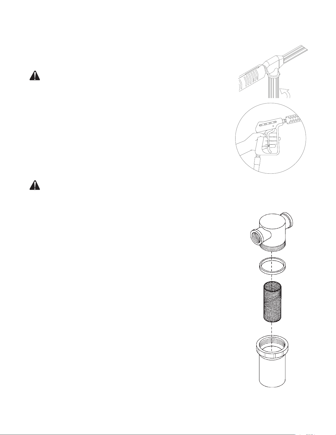
Manual del operador 39
3. Motores de gasolina: Cuando llene el tanque (23), la gasolina debe tener un
mínimo de 85 de octano. NO MEZCLE ACEITE CON LA GASOLINA. Debe
comprarse solamente la gasolina que se vaya a consumir en un periodo
de 30 días. Se recomienda el uso de gasolina limpia, libre de plomo. Se
puede usar gasolina con plomo si no se dispone de gasolina sin plomo.
NO USE gasolina que contenga metanol o alcohol.
ADVERTENCIA ¡RIESGO DE EXPLOSIÓN O INCENDIO! SIEMPRE
ALMACENE EL COMBUSTIBLE LEJOS DE LA LAVADORA
MIENTRAS LA UNIDAD ESTÉ EN FUNCIONAMIENTO O SE
ENCUENTRE CALIENTE.
Combustible del quemador: Cuando llene el tanque (negro), use aceite de
combustible No.1 o No.2/ diesel o queroseno.
4. Revise el nivel de aceite del motor antes de arrancarlo. (Vea el manual del
motor).
5. Vea el manual del motor que se ha proporcionado con esta unidad, para
familiarizarse con los procedimientos apropiados de ajuste.
6. Repase el manual del motor que acompaña a esta lavadora a presión
para familiarizarse con los procedimientos correctos de arranque y
mantenimiento.
CONJUNTO DE VARILLA DOBLE CON PRESIÓN
AJUSTABLE:
ADVERTENCIA ¡RIESGO DE INYECCIÓN QUE PUEDE CAUSAR UNA
LESIÓN GRAVE! LA PISTOLA DE GATILLO SIEMPRE DEBE
ESTAR TRABADA EN SU POSICIÓN CERRADA CUANDO NO
SE USE! ¡NUNCA VEA DIRECTAMENTE HACIA LA BOQUILLA
A MENOS QUE ESTÉ DESCONECTADA DEL CONJUNTO DE
PISTOLA Y VARILLA DOBLE!
Esta unidad tiene un conjunto de varilla doble con presión ajustable que
permite al usuario seleccionar el rocío en abanico a baja o alta presión.
Simplemente gire el mango ajustable de la varilla doble para seleccionar la
presión deseada.
1. Se puede seleccionar la presión alta girando el mango ajustable en el
conjunto de varilla doble en sentido antihorario como se muestra en la
gura siguiente.
2. Se puede seleccionar la aplicación de detergente a baja presión girando
el mango ajustable de la varilla doble en sentido horario como se muestra
en la gura de abajo. Una vez que la presión sea lo sucientemente baja,
el inyector de detergente en la lavadora de presión absorberá detergente
dentro del sistema. Una mezcla de agua y detergente sale por la boquilla
de rocío y por la boquilla de detergente.
CONEXIÓN DE VARILLA DOBLE:
1. Esté seguro que la pistola de gatillo está en la posición de apagado.
2. Conecte la varilla doble a la pistola de gatillo a este tiempo. Asegúrese
que la conexción está apretado seguramente.
SUMINISTRO DE AGUA:
1. Seleccione una manguera de suministro de agua de jardín de buena calidad
que tenga por los menos 3/4” (19 mm) de diámetro interno y no sea mayor
de 50 pies (15,25 m).
2. Revise la malla ltrante de la entrada de agua para asegurarse que esté
limpia y libre de obstrucciones. Conforme se obstruye esta malla, se
restringe el ujo de agua hacia la bomba. Esto puede causar cavitaciones
que provocarán la falla prematura de los empaques de la bomba.
a. Destornille la tapa de la malla ltrante de la unidad.
PRESIÓN ALTA
HACIA LA IZQ.
PRESIÓN BAJA
HACIA LA DER.
MALLA FILTRANTE DE LA
ENTRADA DE AGUA.
INSTALACIÓN Y PREPARACIÓN

40 Manual del operador
b. Retire la malla ltrante y límpiela o reemplácela.
3. Conecte un extremo de la manguera de suministro de agua a la entrada de
agua de la unidad. Conecte el otro extremo de la manguera al suministro
de agua presurizada.
NOTA: Deben observarse los reglamentos locales de su compañía de
agua, al conectar la entrada de agua a las cañerías maestras de
agua. En algunas áreas la unidad no debe conectarse directamente
al suministro público de agua potable. Esto es para asegurar que
no haya realimentación de los detergentes al suministro de agua.
(Se permite la conexión directa si se instala un supresor deflujo de
retroceso.)
NOTA: Si existe un alto grado de contenido mineral en su agua, se reco-
mienda usar un ablandador de agua para prevenir la posibilidad de
una acumulación excesiva de incrustaciones dentro del serpentín del
intercambiador de calor.
4. Siga los requisitos de entrada de agua detallados a continuación:
a. La presión del agua deberá encontrarse entre un mínimo de 20 libras
por pulgada cuadrada (PSI) y un máximo de 125 PSI.
b. El volumen (GPM) de entrada deberá ser aproximadamente un galón
más que el volumen de salida señalado en la placa de la lavadora a
presión. (Usted puede vericar el volumen midiendo el tiempo que
toma llenar un recipiente de 5 galones.)
c. La temperatura del agua que entra no debe exceder los 125º F. Puede
ocurrir un daño excesivo de la bomba si la temperatura del agua
sobrepasa este nivel aceptable.
5. Nunca permita que la unidad opere sin que la línea de agua de entrada esté
conectada y sin que el suministro de agua esté completamente abierto.
DESCARGADOR:
PRECAUCIÓN ¡RIESGO DE DAÑO A LA UNIDAD! ¡NO AJUSTE EN
EXCESO EL DESCARGADOR. SU RUPTURA PUEDE DAR
COMO RESULTADO LA PERDIDA INMEDIATA DE LA PRESIÓN
DEL AGUA Y POR TANTO, REPARACIONES COSTOSAS.
El descargador ha sido preajustado en la fábrica y solo deberá ser ajustado
por un Representante de capacitado para servicio.
VÁLVULA PARA DISIPAR CALOR:
Para asegurar que la temperatura del agua derivada no exceda los niveles
aceptables, nunca permita que la lavadora a presión opere en función de
derivación (con la unidad en funcionamiento y el gatillo cerrado) por más de
tres minutos.
Se ha instalado en esta máquina una válvula para disipar el calor y así pro-
teger la bomba. Puede comenzar a abrirse para sacar agua si la tempera-
tura en la bomba ha excedido los 140ºF. Esto permitirá que entre al sistema
un nuevo suministro de agua fría, impidiendo así la falla prematura de los
empaques de la bomba.
PROCEDIMIENTOS DE INSPECCIÓN ANTES DEL
ENCENDIDO:
Antes de encender la unidad, realice los siguientes procedimientos:
1. Revise el nivel de aceite de la bomba.
2. Revise la malla ltrante de la entrada de agua. Limpie o reemplace de ser
necesario. Vea “Suministro de agua”, #2.
3. Revise todas las conexiones de la manguera para asegurarse de que estén
bien ajustadas. Vea “Suministro de agua”, #3.
INSTALACIÓN Y PREPARACIÓN

Manual del operador 41
4. Inspeccione para asegurarse que no existan fugas de agua, aceite o
combustible del sistema. Si encuentra una fuga de combustible, ¡NO
ENCIENDA LA UNIDAD!0 Vea la sección de advertencias de “Riesgo de
explosión o incendio”. Asegúrese que se hayan reemplazado todas las
partes dañadas y se hayan corregido los problemas mecánicos, antes operar
de nuevo la unidad. Si requiere servicio, llame a la ocina de Servicio a
clientes.
5. Inspeccione las mangueras de alta presión para asegurarse que no tengan
dobleces, rupturas o fugas. Si se encuentra una ruptura o fuga, ¡NO USE
LA MANGUERA! Reemplace la manguera antes de encender la unidad.
Vea “Riesgo de inyección”. Asegúrese que se hayan reemplazado todas
las partes dañadas y se hayan corregido los problemas mecánicos, antes
operar de nuevo la unidad. Si requiere servicio, llame a la ocina de Servicio
a clientes.
INSTALACIÓN Y PREPARACIÓN

42 Manual del operador
ADVERTENCIA
LAS SIGUIENTES PÁGINAS CONTIENEN INSTRUCCIONES SOBRE LA OPERACIÓN Y EL
MANTENIMIENTO.
NO INTENTE OPERAR ESTA LAVADORA A PRESIÓN HASTA QUE HAYA LEÍDO Y
COMPRENDIDO TODAS LAS PRECAUCIONES E INSTRUCCIONES DE SEGURIDAD
SEÑALADAS EN ESTE MANUAL.
¡LA OPERACIÓN INCORRECTA DE ESTA UNIDAD PUEDE CAUSAR LESIONES GRAVES!
¡NO ALTERE NI MODIFIQUE ESTE EQUIPO DE NINGUNA MANERA!

Manual del operador 43
CEBADO DE LA BOMBA:
PRECAUCIÓN RIESGO DE DAÑO A LA UNIDAD ASEGÚRESE QUE
NO ESTÉN CONECTADAS LA MANGUERA, LA PISTOLA O
LA BOQUILLA CUANDO SE ESTÉ CEBADO DE LA BOMBA.
AL CEBADURA SE LIBERAN DEPÓSITOS MINERALES DEL
SISTEMA, LOS CUALES PODRÍAN OBSTRUIR O DAÑAR LA
PISTOLA Y LA BOQUILLA, REQUIRIENDO REPARACIONES
COSTOSAS.
Es esencial cebar la bomba y auir la unidad cada vez que se desconecta
el suministro de agua de la unidad o cuando la unidad estaba descansando
por cualquier tiempo. Esta unidad tiene un serpentín de acero en el que se
torna café o negra el agua residual después de usar la máquina. Esta agua
debe purgarse del sistema antes de encender de nuevo la máquina. Este
procedimiento se debe realizar SIN tener instalados la manguera de alta
presión ni el conjunto de pistola y varilla.
POSICIÓN DE DIRECTA: (UNIDAD TODAS)
1. Abra el suministro de agua.
2. El agua a baja presión comenzará a uir desde el salida de agua. Esto
permite que la unidad se cebe y purgue todo el aire del sistema. La unidad
está cebada cuand el ujo de agua está interrumpido por aire.
3. Una vez que esté cebado, cerrado el suministro de agua y conecte la
manguera de descarga de alta presión a la salida de agua en la unidad.
4. Abra el suministro de agua.
ARRANQUE/OPERACIÓN CON AGUA FRÍA:
1. Vea “Advertencias de seguridad”, antes de encender la unidad.
2. Localice las calcomanías de seguridad en su unidad y ponga atención a
esas advertencias.
3. Asegúrese de que el interruptor del quemador esté en posición de apagado.
PELIGRO ¡RIESGO DE INYECCIÓN QUE PROVOCA LESIONES
GRAVES! ¡MANTÉNGASE COMPLETAMENTE APARTADO DE
LA BOQUILLA! ¡NUNCA COLOQUE LA MANO O LOS DEDOS
DELANTE DE LA BOQUILLA! ¡NO DIRIJA EL CHORRO DE
DESCARGA HACIA PERSONAS O MASCOTAS!
4. Apunte la pistola de gatillo en dirección segura, quite el seguro y apriete
el gatillo. Sostenga el gatillo abierto mientras arranca el motor, según las
instrucciones del fabricante en el manual del motor que acompaña esta
unidad. Apóyese rmemente en caso de que la pistola lo empuje cuando
se encienda la bomba.
5. Una vez que ha arrancado el motor, asegúrese de que el obturador del
motor esté ajustado a la velocidad normal de operación (RPM) y realice
los siguientes procedimientos con la pistola activada:
a. Inspeccione el sistema en busca de fugas de agua, aceite y
combustible.Si encuentra una fuga de combustible, ¡APAGUE LA
UNIDAD INMEDIATAMENTE! Vea las advertencias de “Riesgo de
explosión o fuego”. Asegúrese que se hayan reemplazado todas las
partes dañadas y se hayan corregido los problemas mecánicos, antes
operar de nuevo la unidad. Si requiere servicio, llame a la ocina de
Servicio a clientes.
b. Inspeccione las mangueras de alta presión para asegurarse que no
tengan dobleces, rupturas o fugas. Si encuentra una ruptura o fuga,
¡NO TOQUE LA PARTE DE LA RUPTURA! ¡APAGUE LA UNIDAD
INMEDIATAMENTE! Reemplace la manguera antes de encender la
unidad. Vea las advertencias de “Riesgo de inyección”. Asegúrese que
se hayan reemplazado todas las partes dañadas y se hayan corregido
INSTRUCCIONES DE OPERACIÓN
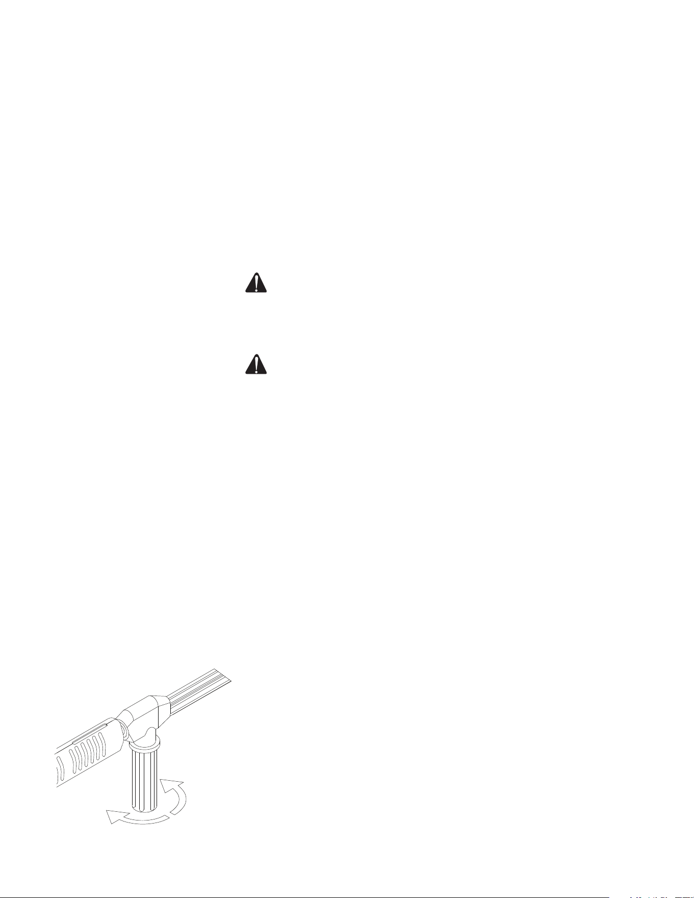
44 Manual del operador
los problemas mecánicos, antes operar de nuevo la unidad. Si requiere
servicio, llame a la ocina de Servicio a clientes.
6. En esta etapa, la unidad está operando como lavadora a presión con agua
fría. Ponga la pistoal algunas veces y trata de ajustar la presión de alta.
¡NUNCA coloque las manos o los dedos delante de la boquilla ni mire
directamente hacia la boquilla. ¡El agua a alta presión puede provocar
lesiones graves!
7. No permita que la unidad opere en función de derivación (con el gatillo
cerrado) por más de tres minutos sin activar el gatillo de la pistola. Si no
se cumple con esta sencilla regla, puede provocarse la falla prematura
de los empaques de la bomba, requiriendo costosas reparaciones de la
bomba.
8. Su lavadora a presión puede atomizar a alta presión en varios patrones
de rocío usando agua fría. Si desea usar agua caliente o detergentes para
limpieza, vea para conocer los procedimientos correctos.
PRECAUCIÓN RIESGO DE DAÑO NO PERMITA QUE EL PATRÓN
DE ROCÍO PERMANEZCA EN UNA ÁREA FIJA DURANTE UN
PERIODO DE TIEMPO PROLONGADO. PUEDE CAUSAR DAÑOS
EN ESA ÁREA.
OPERACIÓN CON AGUA CALIENTE:
ADVERTENCIA ¡RIESGO DE QUEMADURA! LA TEMPERATURA DEL
AGUA PODRÍA SER MUY ELEVADA DURANTE LA OPERACIÓN
CON AGUA CALIENTE. TENGA CUIDADO CUANDO AJUSTE LA
PRESIÓN
1. Siga los pasos señalados en la sección de “Arranque/operación con agua
fría.”
2. Mueva el interruptor del quemador a la posición de ENCENDIDO. Durante
el arranque inicial, el agua comenzará a calentarse en aproximadamente 20
segundos y alcanzará su temperatura máxima en aproximadamente 2-1/2
minutos, siempre y cuando se mantenga oprimido el gatillo. El quemador
se apagará cuando se suelte el gatillo.
NOTA: Mientras esté rociando, es normal que el quemador se enci-
enda intermitentemente. El interruptor de límite alto causará que la
combustión se suspenda cuando la temperatura del agua descar-
gada exceda el límite ajsutado en el interruptor. La combustión se
reiniciará cuando la temperatura del agua descienda por debajo del
ajuste mínimo.
En esta etapa, la unidad está operando como lavadora de presión con agua
caliente. Asegúrese de ser extremadamente precavido cuando ajuste la pre-
sión o controle el conjunto de pistola/gatillo/varilla para evitar la posibilidad
de sufrir quemaduras.
LIMPIEZA CON DETERGENTES BAJA PRESIÓN:
NOTA: Esta función está diseñada para ser usada únicamente con
detergentes suaves. Dado que la solución de limpieza viaja a través
de la bomba y el serpentín del intercambiador de calor, no use cor-
rosivos ya que provocarán daño extenso y representan un peligro
considerable.
1. Vea las advertencias de “Riesgo de lesiones”. Asegúrese de usar vestimenta
protectora como se indicó.
2. Prepare la solución de detergente de acuerdo a las instrucciones en la
etiqueta (Nunca bombee ácidos, alcalinos, líquidos abrasivos o solventes a
través de la unidad. Debido a las características desconocidas y a menudo
corrosivas de muchos detergentes usados comúnmente en la industria de
lavado a presión, se recomienda únicamente el uso de detergentes con
esta unidad).
PRESIÓN ALTA
HACIA LA IZQ.
PRESIÓN BAJA
HACIA LA DER.
INSTRUCCIONES DE OPERACIÓN

Manual del operador 45
3. Sumerja completamente el extremo de la malla ltrante de la manguera
de vinilo transparente en la solución de detergente.
4. Puede el detergente que qiere si encuentra ud el botón ajuste al n de la
manguera claro y vinyl cerca del inyección de detergente. Torce el botón
antihorario completemente para poner el rato maximo de siphón. Esté
seguro que la presa ajustable en la varilla doble está completemente horario
para la operación de presión baja detergente.
NOTA: Este sistema de inyección está diseñado para aplicar detergentes
a baja presión solamente. No permitirá que se introduzcan solucio-
nes de detergente en el sistema a menos que la boquilla del deter-
genet esté instalada en la vara.
5. Para aplicar la solución, quite el seguro de la pistola active el gatillo. En unos
cuantos momentos, una mezcla de detergente y agua saldrá por la boquilla.
Comience a rociar la porción inferior de la supercie que va a lavar y siga
en dirección ascendente, en pasadas largas, superpuestas. Aplicando de
la parte inferior hacia arriba se evitan manchas de escurrimientos. Permita
que se remoje brevemente. Trate de no trabajar en supercies calientes
o expuestas a la luz directa del sol, para reducir las probabilidades de
que el detergente se seque, lo cual podría causar daños a la supercie.
Asegúrese de aplicar la solución de limpieza a una pequeña sección a la
vez.
6. Para enjuagar: je la pistola de gatillo en la posición de APAGADO. Esté
seguro que la presa ajustable en la varilla doble está completemente
anithorario para la operación de presión alta. Quite el seguro de la pistola y
rocíe. Tomará aproximadamente 30 segundos para purgar todo el detergente
de la línea. Para lograr los mejores resultados de enjuague, comience en
la parte superior y avance en forma descendente.
7. Haga pasar por acción de sifón un galón de agua a través del sistema de
inyección de detergente del sistema después de cada uso. Esto evita la
posibilidad de corrosión o acumulación de residuos de detergente, lo cual
provocaría problemas mecánicos durante el siguiente uso.
APAGADO
1. Mueva el interruptor del quemador a la posición de APAGADO.
2. Apriete el gatillo y descargue el agua durante tres minutos para enfriar
el intercambiador de calor y la manguera de alta presión. (Un periodo de
enfriamiento insuciente de la manguera de alta presión causará desgaste
excesivo y la ruptura eventual de la manguera.)
3. En los modelos de motor de gasolina, NO CIERRE el obturador para
detener el motor. Podría ocasionarse petardeo o explosión en el carburador
y pposible daño al motor.
4. Mueva el interruptor de encendido/apagado del motor a la posición de
APAGADO.
5. Mueva el valvula de combustible del motor a la posición de CERRADO.
6. Abra el suministro de agua y accione el gatillo de la pistola por un momento
para aliviar la presión.
7. Desconecte la manguera de alta presión, la pistola y la varilla. Drene y limpie
la unidad con un paño. Almacénela donde no corra riesgo de congelación.
INSTRUCCIONES DE OPERACIÓN

46 Manual del operador,
MANTENIMIENTO ESPECIFICO:
v: En el instructivo del motor que viene con su unidad se detallan los
procedimientos especícos para dar mantenimiento al motor. Si sigue las
recomendaciones del fabricante prolongará la duración de su motor.
BOMBA: Cambie el aceite de la bomba después de 50 horas de operación.
Después del cambio inicial, el fabricante recomienda cambiar el aceite
cada 3 meses o a intervalos de 250 horas. Si el aceite tiene aspecto sucio
o lechoso, quizá sea necesario hacer cambios más frecuentemente. Use
aceite 15W20 detergente para bombas y solo llene hasta el centro de la
mirilla de nivel. NO LLENE DEMASIADO.
ACOPLADORES RÁPIDOS: Dentro de lo acopladores hay sellos anulares
que eventualmente se deteriorarán. Para reemplazarlos, simplemente in-
stale un sello anular de repuesto para corregir la fuga. Puede adquirir sellos
anulares adicionales con su distribuidor.
BOQUILLA: El ujo de agua a través de la boquilla de rocío causará erosión
del oricio, ensanchándolo y provocando una pérdida de presión. Deben re-
emplazarse las boquillas siempre que la presión llegue al 85% del máximo.
La frecuencia del reemplazo depende de variables tales como el contenido
mineral en el agua y la cantidad de horas que se use la boquilla.
SEPARADOR DE AGUA Y COMBUSTIBLE: Ocasionalmente, debe drenarse
el agua del separador. Siga los procedimientos detallados a continuación:
1. Revise el recipiente colector diariamente.
2. Asegúrese que la unidad esté apagada y ponga un colector de aceite
debajo del cartucho de combustible.
3. Aoje el tapón de drenaje para permitir que los contaminantes del
combustible/agua uyan al colector de aceite.
4. Vuelva a apretar el tapón de drenaje cuando haya terminado.
5. Deseche el material drenado de acuerdo sigiendo los reglamentos
ambientales de su área.
AJUSTE DE AIRE DEL QUEMADOR: El regulador de aire ha sido ajustado
previamente en la fábrica para una operación normal entre el nivel del mar y
una altura de 2000 pies sobre el nivel del mar en condiciones estándar (60ºF
de temperatura del agua y del aire). Para asegurar la máxima eciencia de
combustión en temperaturas más bajas y mayor altitud, será necesario au-
mentar el suministro de aire hacia la cámara de combustión. Se recomienda
una prueba de mancha de humo durante el ajuste de del regulador de aire.
Esto ayudará a maximizar la eciencia del quemador y evitará la operación
inecaz y la formación excesiva de hollín en el serpentín del intercambiador
de calor.
1. La máquina debe estar en funcionamiento y el quemador debe estar
ENCENDIDO.
2. Haga una prueba de mancha de humo para determinar si se requiere más
o menos aire para una combustión apropiada.
a. Si la prueba da como resultado humo que sobrepasa el No.3, gire el
brazo del regulador en sentido antihorario para aumentar el ujo de
aire hacia la cámara de combustión.
b. Si la prueba da como resultado un color amarillento, gire el brazo del
regulador en sentido horario para reducir el ujo de aire hacia la cámara
de combustión.
3. Sostenga el brazo de ajuste del regulador de aire y aoje la tuerca de
jación. Mueva la compuerta del regulador en incrementos de 1/8” y vuelva
a apretar la tuerca de jación después de cada movimiento de 1/8”.
4. Lentamente, accione y suelte el gatillo de la pistola para asegurarse de
que haya ignición adecuada. Se considera favorable una emisión de humo
leve o nula al encender, y una prueba de mancha de humo menor al No.3.
ALMACENAJE Y MANTENIMIENTO

Manual del operador 47
ALMACENAJE Y MANTENIMIENTO
5. Repita los pasos 2 y 3 hasta lograr un buen resultado en el paso 4.
FUGAS: Elimine rápidamente cualquier fuga encontrada en el sistema de
bombeo quitando las piezas sospechosas, aplicando sellador de rosca a los
tornillos y reinstalando.
NOTA: Si usa cinta de teflón, asegúrese de que no penetre ningún trozo
de cinta a la tubería del sistema para evitar la posibilidad de tapona-
miento en la boquilla de rocío.
PREPARACION PARA EL INVIERNO:
ADVERTENCIA ¡RIESGO QUE LA UNIDAD REVIENTE! ¡NO
ALMACENE/OPERE LA UNIDAD EN UN AMBIENTE HELADO!
1. Será necesario preparar esta unidad para el invierno, para nes de
Almacenamiento y transporte en temperaturas ambiente inferiores al punto
de congelación. Esta unidad debe protegerse contra la temperatura más
baja incurrida por las siguientes razones:
a. Si se congela cualquier parte del sistema de bombeo puede acumularse
una presión excesiva en la unidad, lo que podría causar que la misma
reviente resultando en lesiones posibles graves al operador o a los
observadores.
b. El sistema de bombeo de esta unidad puede resultar dañado
permanentemente si se congela. LOS DAÑOS POR CONGELACION
NO ESTAN CUBIERTOS POR LA GARANTIA.
Usted puede proteger su unidad siguiendo el procedimiento indicado abajo,
si debe almacenarla en un lugar donde la temperatura puede descender por
debajo de los 32°F.
1. Reúne los artículos siguientes:
a. Dos recipientes de 5 galones.
b. Un galón de anticongelante. (El fabricante recomienda un anticongelante
seguro para el medio ambiente.)
c. Suministro de agua.
d. Una manguera de tres pies de largo con un D.I. de 1/2-3/4 y con un
adaptador macho de manguera de jardín de 3/4 de pulgada.
2. Procedimiento:
a. Para comenzar a preparar su unidad para el invierno, la misma debe
hacerse funcionar y cebarse de acuerdo con los “Procedimientos de
Arranque” indicados.
b. Apague la unidad y corte el suministro de agua, después de hacerla
funcionar y cebarla.
c. Elimine la presión del sistema apuntando la pistola a gatillo hacia una
dirección segura y accionando el gatillo hasta que el ujo de agua cese
de salir por la lanza doble.
d. Asegure la pistola a gatillo en la posición OFF y retire la lanza doble.
e. Retire la manguera de suministro de agua de la unidad y je seguramente
la manguera de 3 pies a la conexión de entrada.
f. Si fuera aplicable apague el inyector de detergente.
g. Llene con agua un balde de 5 galones.
h. Manteniendo la manguera de 3 pies en una posición vertical, llénela
completamente con agua. A continuación tapone la salida de la
manguera con su dedo pulgar u otro dedo. Coloque el extremo
taponado dentro del balde de agua de 5 galones.
i. Arranque la unidad. Accione varias veces el gatillo de la pistola hasta
que todo el aire haya salido del sistema (la unidad está cebada). Puede
ser necesario disminuir las RPM del motor a funcionamiento en vacío
para ayudar el cebado.
32˚F 0˚C
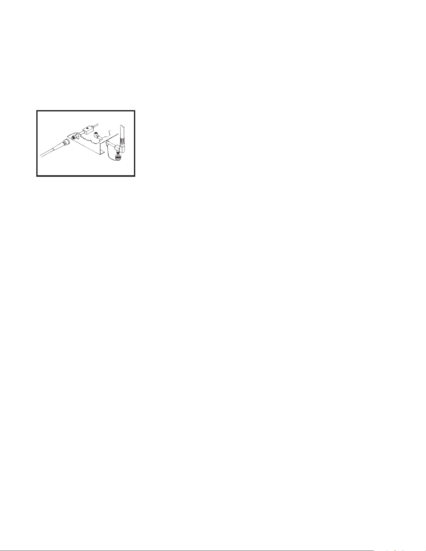
48 Manual del operador
TAPÓN DE DRENAJE DEL
SERPENTÍN
NOTA: La preparación apropiada para el invierno está basada en las
instrucciones recomendadas del fabricante incluidas en la “Tabla
de Protección” mostrada en el rótulo posterior de la mayoría de los
recipientes de anticongelantes.
j. Por medio de la acción de sifón extraiga suciente agua del balde de
5 galones hasta que haya justo suciente agua restante para mezclar
con el anticongelante, con la pistola a gatillo mantenido abierto.
k. Apunte la vara hacia el recipiente vacío.
l. Accione el gatillo de la pistola hasta que el anticongelante comience a
salir por la vara. Suelte el gatillo por 3 segundos, a continuación accione
el gatillo de la pistola por 3 segundos. Continúe ciclando la pistola
varias veces hasta que toda la mezcla anticongelante es extraída del
recipiente por la acción de sifón.
m. Separe la manguera de 3 pies de la unidad y drene todo el exceso
restante de anticongelante dentro del reciente de 5 galones.
n. Desconecte el conjunto de manguera/pistola/vara de la unidad y drene
todo el exceso restante de anticongelante dentro del recipiente de 5
galones.
o. Almacene la manguera, la lanza doble y vara junto con la unidad, en
un lugarseguro.
p. Almecene la solución anticongelante para un uso ulterior o descártela
de acuerdo con las leyes de protección del medio ambiente
correspondientes.
3. Procedimiento opcional:
a. Apague la unidad y corte el suministro de agua.
b. Elimine la presión del sistema apuntando la pistola a gatillo hacia una
dirección segura y accionando el gatillo hasta que el ujo de agua cese
de salir por la lanza doble.
c. Desconecte y drene la manguera, lanza doble y la vara.
d. Quite el tapón de drenage del serpentín a la entrada del intercambiador
de calor.
e. Arranque la unidad y permita que funcione hasta que toda el agua
salga de la misma. Apague una vez que el agua ha cesado de uir de
la unidad.
NOTA: Debe ejercerse precaución al usar este procedimiento, ya que
pueden formarse plaquitas de hielo de las gotas de agua, lo que
podría causar que la unidad reviente si se arranca antes de estar
completamente descongelada.
ALMACENAJE Y MANTENIMIENTO
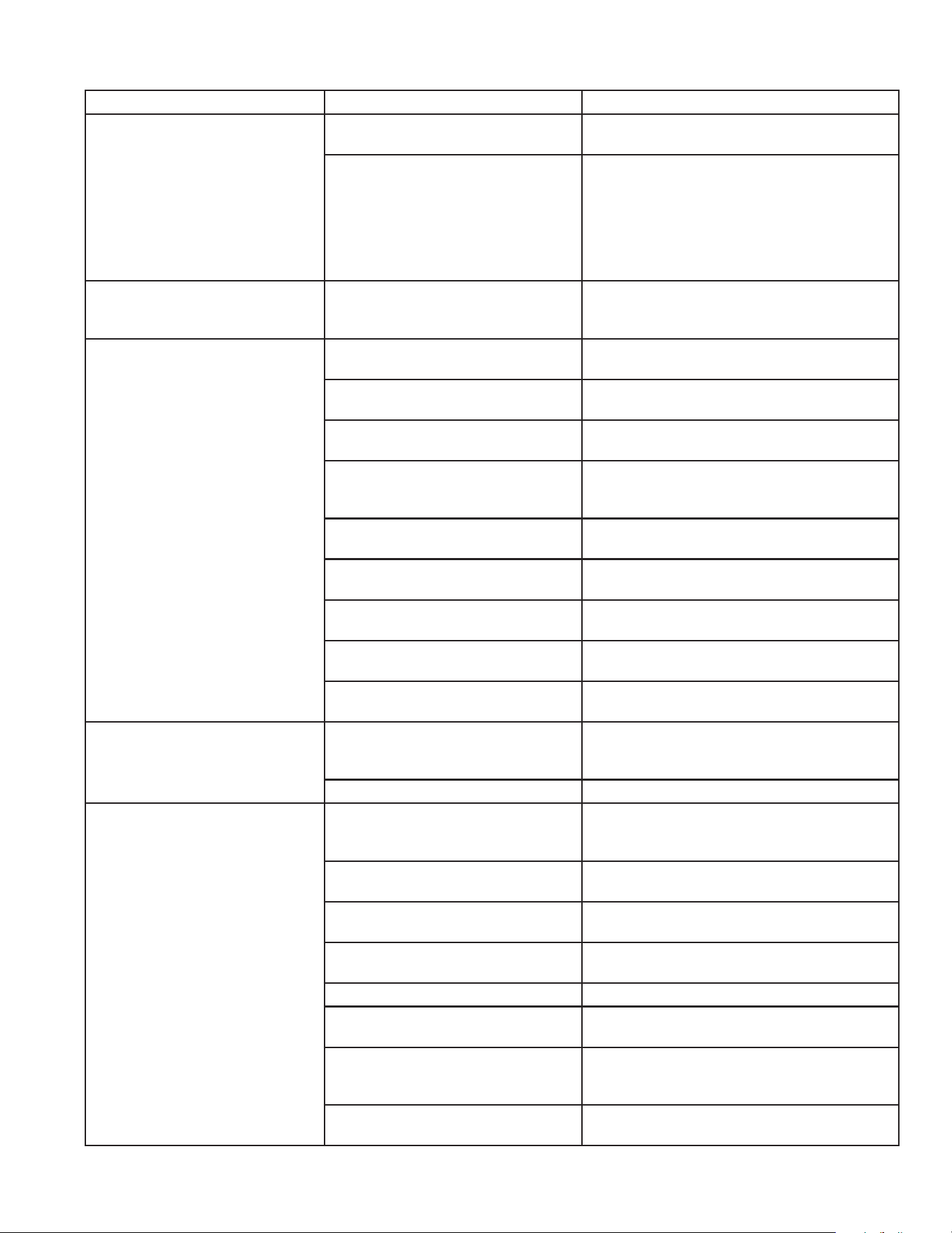
Manual del operador 49
LOCALIZACION DE FALLAS
SINTOMA CAUSA PROBABLE SOLUCION
El motor no arranca. Problemas con el motor. Vea el manual del motor que viene con su
unidad.
Los componentes de la unidad
están congelados.
Permita que se descongele Si alguna
parte de la unidad se congela, es posible
que se acumule la presión, lo cual podría
ocasionar que la unidad reviente y conse-
cuentemente provoque lesiones graves al
operador o las personas que se encuentren
alrededor.
No hay descarga de la boquilla
cuando se acciona el mecanis-
mo del gatillo.
Suministro inadecuado de agua. Asegúrese que la manguera tenga 3/4”
de diámetro y que el suministro de agua
entrante esté abierto.
Presión baja o uctuante Doblez en la manguera de entrada
de agua.
Elimine el doblez
Doblez en la manguera de des-
carga de alta presión.
Reemplace la manguera.
Está obstruido el tamiz de la en-
trada de agua.
Saque el tamiz, limpie o reemplace.
La bomba absorbe aire (Eliminado
el cebado)
Ajuste todas las conexiones de entrada
de agua. Elimine dobleces en la tubería de
entrada.
Gatillo de lanza dual no esta en
hoda de presion alto.
Gire el gatillo en sentido contrario a las
agujas del reloj presion alto.
La boquilla de rociado está obstru-
ida o gastada.
Saque, limpie o reemplace.
El conjunto de la válvula en la
bomba está dañado o obstruido.
Saque, inspeccione, limpie o reemplace.
Los empaques de la bomba están
gastados.
Reemplace los empaques.
La válvula de derivación no opera
correctamente.
Repare o reemplace.
Pérdida de agua de la “Válvula
de descarga térmica”
La temperatura del agua es de-
masiado elevada.
No permita que la unidad opere en el modo
de derivación (con la pistola a gatillo cer-
rado) durante más de tres minutos.
Válvula defectuosa. Reemplace.
El detergente no uirá por sifón
en el modo de detergente a baja
presión.
El tamiz del detergente no está
completamente sumergido en la
solución de detergente.
Inspeccione, sumerja si fuera necesario.
El tamiz del detergente está ob-
struido.
Inspeccione, limpie o reemplace.
La manguera del detergente está
cortada, obstruida o doblada.
Inspeccione, limpie o reemplace.
La perilla de ajuste del detergente
está girada a la posición cerrada.
Abra la perilla de ajuste. Reérase a “Limp-
ieza con detergentes”
No está en el modo baja presión. Inserte la buquilla 6540° (NEGRA)
La boquilla del detergente está
taponada.
Limpie o reemplace.
Hay demasiadas extensiones de
las manguereas de alta presión
cenectadas a la salida de agua.
Use una extensión como máximo.
La esfera y el resorte en el Venture
están atascados.
Retire, limpie o reemplace.
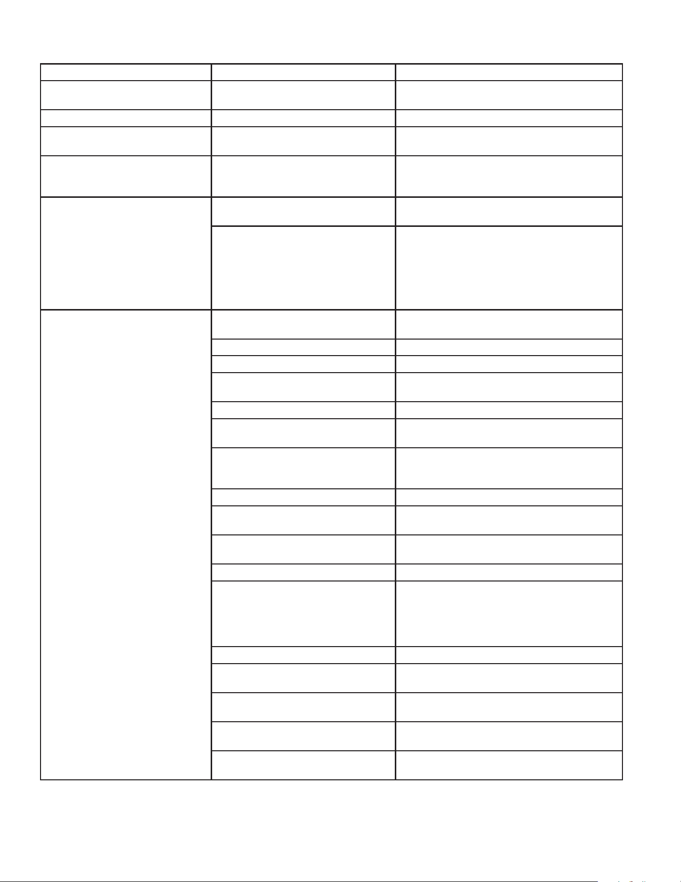
50 Manual del operador
LOCALIZACION DE FALLAS
SINTOMA CAUSA PROBABLE SOLUCION
El agua parece lechosa o espu-
mosa
Agua en el aceite Cambie la bomba de aceite. Llene al nivel
apropiado.
Pérdida de aceite de la unidad Sulos o argollas gastados. Contact Service.
El ujo de agua retrocede al
recipiente del detergente.
La esfera y el resorte en el Venture
están atascados.
Retire, limpie o reemplace.
Cuando la pistola de gatillo está
asegurado en la posición “OFF”,
el agua uye desde la boquilla.
La pistola funciona mal. Repare o reemplace.
Agua está saliendo debajo del
rollo caliente intercambo.
El tapón de drenaje del serpentín
no estáinstalado.
Instale el tapón.
El aparato de seguridad está salida
de agua debido a una falla de
un descargador o interruptor de
presión.
1. Diagnostique y corrija el problema del
descargador o interruptor de presión.
2. Reemplace el aparato de seguridad
contra estallidos. NUNCA active la
unidad sin un aparato de seguridad. Podría
causar una explosión.
Quemador no encendia. Varilla no está en posición que-
mada.
Examine posición de varilla.
No hay combustible. Más combustible.
Gatillo está cerrado. Abre el gatillo para presión.
La correa de impulso electromotríz
está oja o rota.
Ajuste o reemplace según sea necesario.
Acoplador reguable roto. Reemplace.
Filtro combustible/separador del
aqua sucio o atascado.
Desaque o reemplece como es necesario.
Bomba combustible esta absor-
bandos el aire.
Apriete todas las conexiones de entrada de
combustible. Elimine las fugas en la línea
de entrada.
Bomba combustible no funciona. Examine la presión reemplece se necesita.
Filtro repunte combustible esta
obstruir.
Llame al Departamento de Servicio.
Boquilla combustilbe sucia o atas-
cado.
Reemplace.
Falla del módulo de encendido. Llame al Departamento de Servicio.
Los electrodos de ignición están
dañ ados o desgastodos.
Con la unidad en funcionamiento y el gatillo
de la pistola en posición cerrada, vea por
medio de la mirilla del quemador para
aseguararse que hay chispas en los elec-
trodos.
No hay voltaje. Llame al Departamento de Servicio.
Varilla de presion está fatigando Presión debe estar más a 250 PSI/18 Bar a
permetir quemadura encender.
Varilla de los limitos altos está
fatigando.
Permite la unidad a calmar antes de
encendo.
Ajustameinto del aire quemado
incorrecto.
Ajuste como se dice
Valvula del combustible no fun-
ciona.
Reemplece.
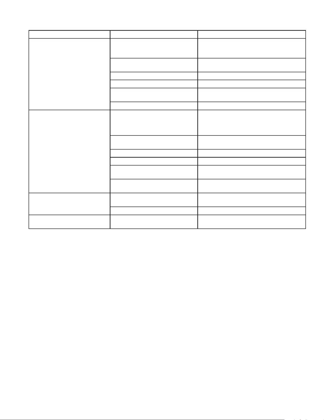
Manual del operador 51
LOCALIZACION DE FALLAS
SINTOMA CAUSA PROBABLE SOLUCION
Quemadura funciona irregular. Hay aqua en petroleo. Desaugue ltro combustilbe y agua sepera-
dor. Desaugue depósito combustible y
reemplece con combustible limpio.
Filtro combustible / aqua separa-
dor sucio.
Reemplece el elemento.
Tobera combustilbe sucio. Reemplece.
Ajustamiento malo del aire. Ajuste como se dice
Filtro repunte combustible esta
obstruir.
Llame al Departamento de Servicio.
Bomba combustible no funciona. Reemplece.
Quemadura funciona pero no
acolorar.
Combustible malo o incorecto. Examine combustible a ser seguro que
está correcto. Desaugue el depósito y
reemplece el ltro si es necesario y reponga
combustible.
Presión del combustible bajo. Examine la presión del combustible y reem-
plece si es necesario.
Tobera combustible sucio. Reemplece.
Ajustameinto del aire incorrecto. Ajuste como se dice
Filtro repunte combustible esta
obstruir.
Llame al Departamento de Servicio.
Hay escama en el rollo calentiente
intercambia.
Llame al Departamento de Servicio.
Quemadura descarga humo
blanco.
No hay mucho combustible. Ponga más combustible. Si todavia hay
humo blanco llame los servicios.
Hay aire exesivo. Ajuste como se dice
Quemadura descarga humo
negra.
No hay bastante aire. Ajuste como se dice

52 Manual del operador
TABLA DE MANTENIMIENTO
PROCEDURE Cada Dia 3 Meses 6 Meses 9 Meses 12 Meses
Examine del nivel de aceite del motor •
Cambie del aceite del motor***** • • • •
Examine nivel del petroleo bomba •
Cambie petroleo de bomba** • • • •
Examine ltración de petroleo •
Examine ltración de combustible •
Examine ltración del agua •
Examine la manquera •
Examine ltro agua entrada •
Examine ltro combustible/
agua seperado •
Examine de correas • • • •
Reponga tobera alta presión*** • • • •
Reponga ltro combustible/
agua separado •
Examine ltro de bomba combustible* •
Reponga tobera combustible* •
Examine aire quemadura regulable • • • •
Examine quemadura electrodos* •
Pruebe la presión del aqua* • • • •
Pruebe la presión de combustible* • • • •
Pruebe temperatura del aqua* • • • •
Quite escama del rollo**** •
* Debe realizar esto un técnico de servicio autorizado.
** Ud tiene que cambiar combustible de bomba despúes de las primeras cincuenta (50) horas. De la operación y
cada (250) horas o 3 meses, cualquiera.
*** Las bouqilla de alta presión deben reemplazarse siempre que la presión sea inferior al 85%.
**** Hay una diferencia con la acumulacion de escama con minerales en el aqua y la cantidad de usos. Tiene que quitar
escama cada mes o cada año.
*****El aceite del motor debe cambiarse después de las primeras 8 horas de operación y cada 50 horas o 3 meses, lo
que ocurra primero.

Manual del operador 53
*Necesita 17-0028 1/4 Conecta rapida a hembra
**Necesita 17-0004 3/8 Conecta rapida a hembra.
***PSI y GPM tienen que se especifacada cuando esta ordena.
ACCESORIOS
Detergents de son detergentes expecialmente para usar con lavadoras a presion de & estan envasando
en dimensiones varios.
15-0006 MANGUERA ABASTECER DE AGUA 3/4” XX
XX
50-0136 CARRETE MANGUERA 13” (PUEDE MANTERNÉR 100’) XX
XX
50-0137 CARRETE MANGUERA 16” (PUEDE MANTERNÉR 200’) XX
XX
AW-0050-0138 MÉNSULA DE LA MANGUERA XX
XX
50-0140 MÉNSULA DE LA MANGUERA (22” BAR) X
852-0138 MANGUERA PARA CARRETE MANGUERA (4000 PSI) XXX
852-0139 MANGUERA PARA CARRETE MANGUERA (4000 PSI) X
AW-3000-0035 BOQUILLA ARENA ACRIBILLAR*
XX
X
AW-3000-0004 BOQUILLA ARENA ACRIBILLAR
*X
AW-4085-0016 PETROLEO DE BOMBA XX
XX
AW-7004-0045 BOQUILLA GIRATORIA (.045 / 5000 max) *XXXX
AW-7003-1500 CEPILLO GIRATORIO
*X
XXX
AW-7018-1200 VARA EXTENSIÓN 12’ ** (3000 PSI) XX
AW-7018-1800 EVARA EXTENSIÓN 18’ ** (3000 PSI) XX
AW-7018-2400 VARA EXTENSIÓN 24’ ** (3000 PSI) XX
AW-7020-8003 LIMPIA DE SUPERFICIE ROTATORIO** (20” 4000 PSI) XX
XX
AW-7020-8001 LIMPIA DE SUPERFICIE ROTATORIO** (28” 4000 PSI) XX
XX
AW-7025-8000 25” ESCOBA MECANICO (5 - 80° BOQUILLA)*/*** XX
XX
AW-7035-8000 35” ESCOBA MECANICO (7 - 80° BOQUILLA)*/*** XX
XX
HSP-2503
HSP-3004
HSP-3504
HSP-4004

54 Manual del operador
DECLARACIÓN DE GARANTÍA
Mi-T-M garantiza todas las piezas (excepto las piezas a las cuales se hace referencia
más abajo) de su nueva lavadora a presión SERIE HSP contra defectos en sus materia-
les o su manufactura durante los períodos siguientes:
Para un curso de la vida (limitado) contra congelar y agrietarse:
Colector de bomba
Por siete (7) años a partir de la fecha de compra:
La bomba de alta presión
Por tres (3) años a partir de la fecha de compra:
El serpentín del intercambiador de calor
Por una (1) años a partir de la fecha de compra:
La bomba de alta presión Estructura Polea Protecciones
El sistema de encendido eletromagnético (EMF) Tubería
Por noventa (90) días a partir de la fecha de compra:
Interruptores de control Interruptores de seguridad Válvula reguladora
Bomba de combustible Interruptores de presión Electrodos
Válvula de auxilio seguridad Interruptores de temperatura
Termostato de límite arriba Válvula de descargas Valvula de combustible
Por treinta (30) días a partir de la fecha de compra:
Manguera de alta presión Pistola de gatillo Mallas/Filtros
Durante el período de garantía, se repararán o reemplazarán a discreción de manufactu-
rar las piezas defectuosas que no estén sujetas a un desgaste normal. El reembolso en
cualquier caso se limitará al precio de compra.
EXCLUSIONES
1. El motor está cubierto bajo una garantía por separado que su respectivo fabricante
ofrece, y queda sujeto a los términos establecidos en dicha garantía.
2. Piezas sujetas a desgaste normal:
Empaques de la bomba Boquillas atomizadoras Correas
Válvulas de la bomba Conectores roscados Válvulas de detergente
Filtros de combustible
3. Esta garantía no cubre piezas dañadas a causa de desgaste normal, aplicación in
correcta, uso incorrecto, o operación a velocidades, presiones o temperaturas diferentes
a las recomendadas. Tampoco se garantizan las piezas dañadas o des gastadas debido
al uso de líquidos cáusticos o a la operación en ambientes abrasivos o corrosivos, o
bajo condiciones que causen cavitación de la bomba. También se anula la garantía si
no se siguen los procedimientos recomendados de operación y mantenimiento.
4. El uso de piezas que no sean genuinas anulará la garantía. Las piezas enviadas con porte
prepagado a la fábrica de o a un centro de servicio autorizado serán inspeccionadas y
reemplazadas sincargo alguno si se encuentran defectuosas y están cubiertas por la
garantía. No hay otras garantías que se extiendan más allá de la descripción presentada
aquí. no será responsable bajo ninguna circunstancia por pérdida de uso del aparato,
pérdida de tiempo o renta, inconve niencia, pérdida comercial o daños consecuentes.

Manual del operador 55

56 Manual del operador