This manual must only be used by
a qualified heating installer / service
technician. Read all instructions,
including this manual and the
Veritus Water Heater Service
Manual, before installing. Perform
steps in the order given. Failure
to comply could result in severe
personal injury, death, or substantial
property damage.
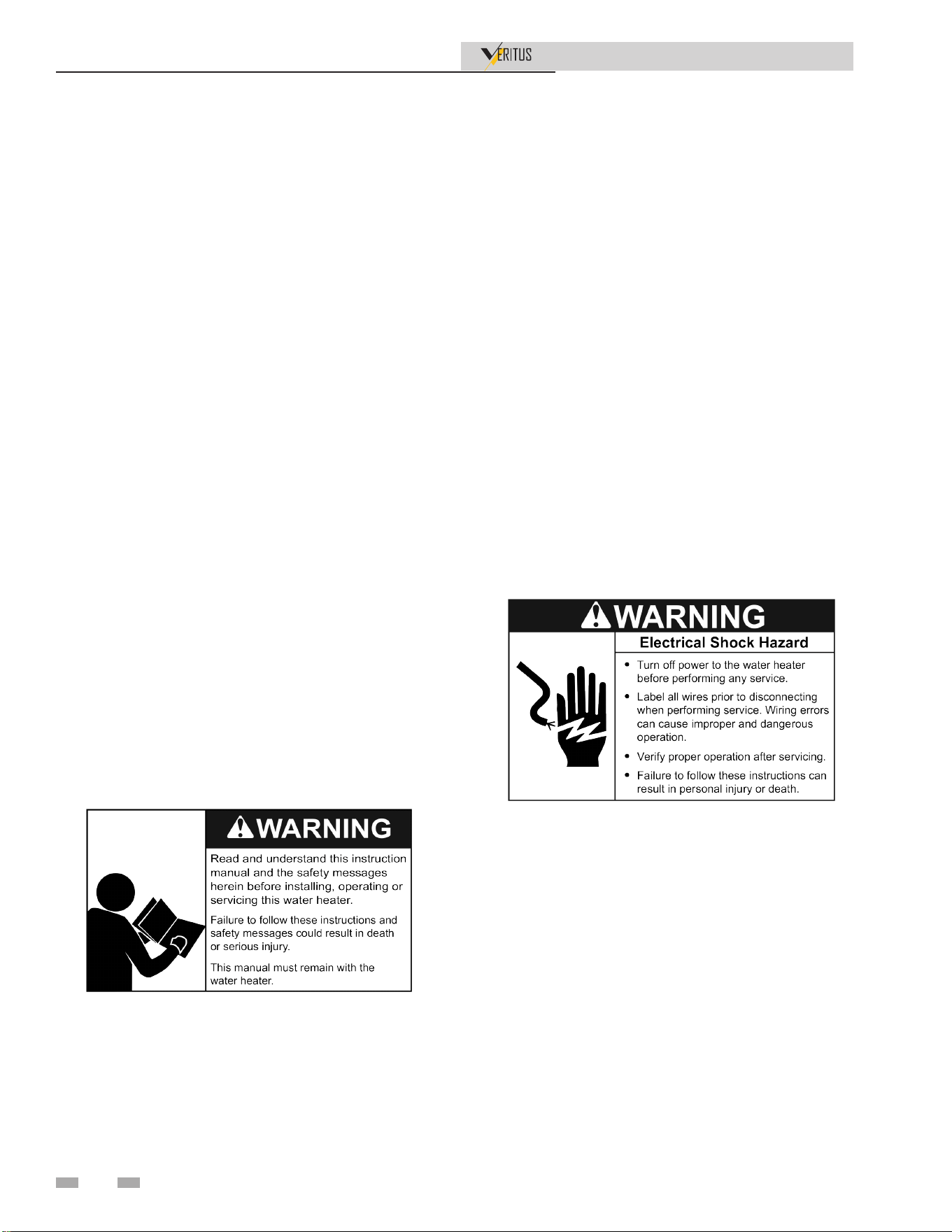
⚠WARNING
Save this manual for future reference.
100371005_2000627791_Rev L
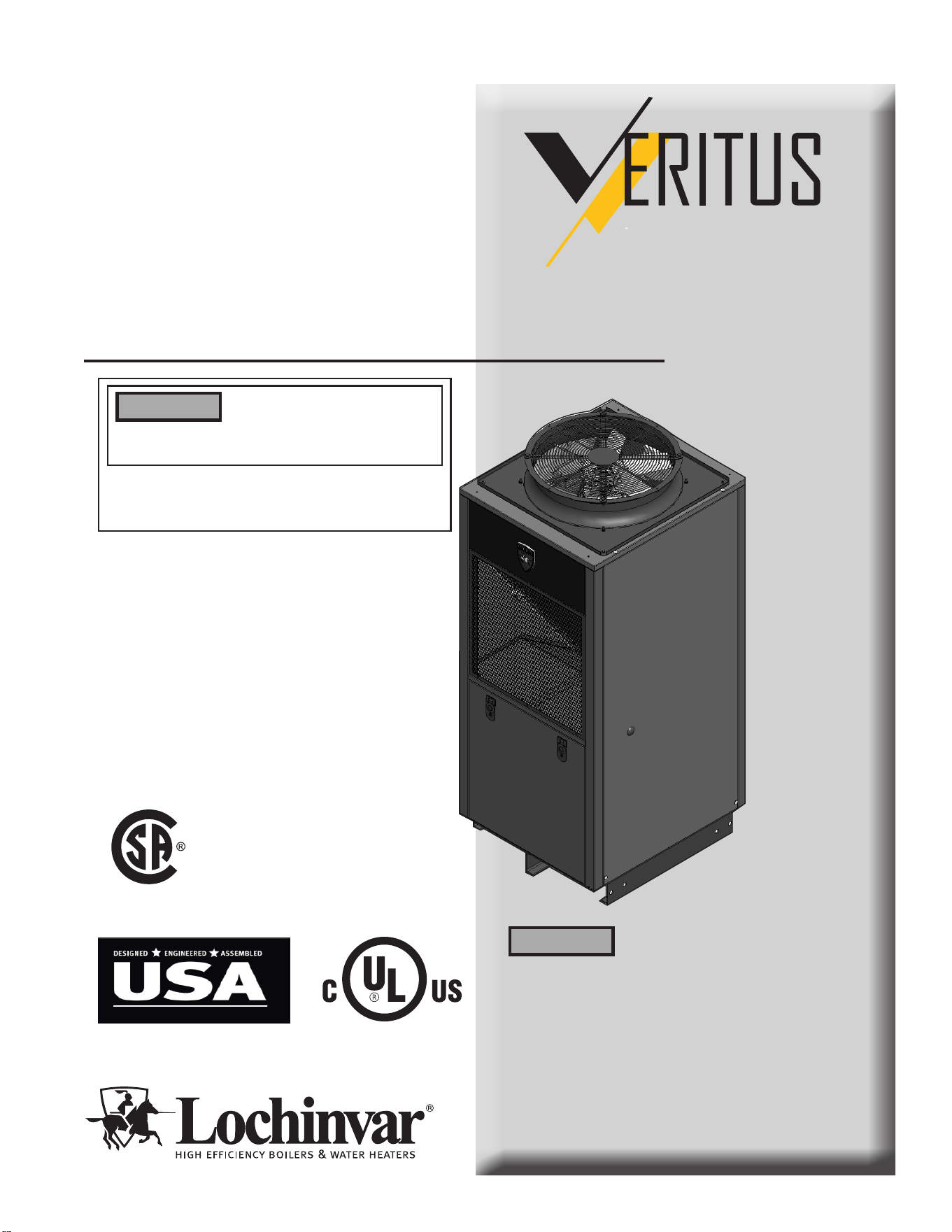
Installation & Operation Manual
Models: 60 - 350*
Series: 100
-- Installation and service must be performed by a
qualied installer or service agency.
⚠WARNING
If the information in this manual
is not followed exactly, electrical
shock or excessive pressure may result causing
property damage, personal injury, or loss of life.
LOW LEAD CONTENT
*Models 200 through 350 are composed of combinations
of models 60 and 140 which are the certified units.
AIR SOURCE HEAT PUMP WATER HEATER
™

2
Contents
HAZARD DEFINITIONS ................................................... 3
PLEASE READ BEFORE PROCEEDING ...................4-5
INTRODUCTION ............................................................6-7
Installer Qualifications ...................................................... 6
Preparing for Installation ............................................... 6-7
THE VERITUS WATER HEATER - HOW IT WORKS .. 8-15
Components ................................................................8-12
Principle of Operation .................................................... 13
The Refrigeration Cycle ................................................. 13
Air/ Water Temperature Range ...................................... 14
Refrigerant Charge ........................................................ 14
Storage Recommendations/ Equipment Disposal ......... 14
Product Summary .....................................................14-15
PERFORMANCE ............................................................. 16
1. DETERMINE WATER HEATER LOCATION
Indoor/Outdoor Installation/Clearances ........................17-18
Provide Air Openings to Room ......................................... 19
Flooring Foundation .......................................................... 19
Seismic Bracing................................................................. 19
Vent and Air Ducts ............................................................ 19
Air Temperature ................................................................ 19
Electrical Requirements .................................................... 19
Corrosive Contaminants and Sources .............................. 20
2. PREPARE WATER HEATER
Remove Water Heater From Wood Pallet ........................ 21
Storage & Handling ........................................................... 21
Assemble Manifold ............................................................ 22
3. INSTALLING WATER HEATER
Required Ability ................................................................. 23
Required Tools & Material ................................................ 23
Unit Placement .................................................................. 23
Electrical Connections ....................................................... 24
Water Connections ............................................................ 24
Single Tank Configuration ................................................. 25
Multi-Tank Preheat Configuration ..................................... 25
Condensate Drain Line ..................................................... 25
Standard Tank Thermostat ............................................... 25
Water Temperature ........................................................... 25
4. SYSTEM PIPING
System Water Piping Method ........................................... 26
Water Connections ............................................................ 26
General Piping Information ............................................... 26
Cold Water Supply ............................................................ 26
Water Pressure ................................................................. 26
Closed Water Systems ...................................................... 26
Water Chemistry................................................................ 26
Condensate Removal ........................................................ 26
Contaminated Water ......................................................... 26
Scalding ............................................................................. 27
Piping Components ........................................................... 27
Temperature Sensor Installation ....................................... 28
Tank Selection .................................................................. 28
Solar Tanks ....................................................................... 28
Piping Diagrams ........................................................... 30-38
5. AIR FLOW AND DUCTING
General Guidelines ........................................................... 39
Duct Sizing ........................................................................ 39
Duct Insulation .................................................................. 39
Make Duct Connections .................................................... 39
Ducting Multiple Units ....................................................... 39
Building Air Pressure ......................................................... 39
Negative Pressure ............................................................. 39
Positive Pressure .............................................................. 39
When to Install Ducting ..................................................... 39
Supply Air Ducting ............................................................. 40
Return Air Ducting ............................................................. 41
6. OUTDOOR INSTALLATIONS
Outdoor Air Inlet and Outlet .............................................. 42
7. FIELD WIRING
Line Voltage Connections ................................................. 43
Low Voltage Connections ................................................. 46
Wiring of the Cascade ....................................................... 47
8. INSTALLATION CHECKLIST ..................................... 49
9. START-UP ..............................................................50-55
10. OPERATING INFORMATION
General .............................................................................. 56
Cascade ............................................................................ 58
Sequence of Operation ..................................................... 59
11. MAINTENANCE
Maintenance and Annual Start-up .................................... 61
12. DIAGRAMS
Ladder Diagram ................................................................ 69
Wiring Diagram.............................................................70-73
Revision Notes ................................................... Back Cover
Installation & Operation Manual
3
Hazard definitions
The following defined terms are used throughout this manual to bring attention to the presence of hazards of various risk levels or
to important information concerning the life of the product.
⚠DANGER
⚠WARNING
⚠CAUTION
CAUTION
NOTICE
DANGER indicates an imminently hazardous situation which, if not avoided, will result in death or serious
injury.
WARNING indicates a potentially hazardous situation which, if not avoided, could result in death or serious
injury.
CAUTION indicates a potentially hazardous situation which, if not avoided, may result in minor or moderate
injury.
CAUTION used without the safety alert symbol indicates a potentially hazardous situation which, if not
avoided, may result in property damage.
NOTICE indicates special instructions on installation, operation, or maintenance that are important but not
related to personal injury or property damage.
Installation & Operation Manual
4
Please read before proceeding
Read all instructions, including this manual
and the Veritus Water Heater Service
Manual, before installing. Perform steps in
the order given.
Have this water heater serviced/ inspected
by a qualified service technician, at least
annually.
Failure to comply with the above could
result in severe personal injury, death, or
substantial property damage.
Failure to adhere to the guidelines on this
page can result in severe personal injury,
death, or substantial property damage.
When calling or writing about the water
heater – Please have the water heater model
and serial number from the water heater
rating plate.
Consider piping and installation when
determining water heater location.
Any claims for damage or shortage in
shipment must be filed immediately
against the transportation company by the
consignee.
Factory warranty (shipped with unit) does
not apply to units improperly installed or
improperly operated.
If the information in this manual is not
followed exactly, electrical shock or
excessive pressure may result causing
property damage, personal injury, or loss
of life.
⚠WARNING
NOTICE
⚠WARNING
⚠WARNING
System contains oil and refrigerant under
high pressure. Recover refrigerant to relieve
pressure before opening refrigeration
system. See unit label for refrigerant type.
Do not use non-approved refrigerants,
refrigerant substitutes, or refrigerant
additives.
Failure to follow proper procedures or
the use of non-approved refrigerants,
refrigerant substitutes, or refrigerant
additives could result in death or serious
injury or equipment damage.
⚠WARNING
When servicing the water heater –
⚠WARNING
DO NOT install units in rooms or
environments that contain corrosive
contaminants (see Table 1-3 on page 20).
Failure to comply could result in severe
personal injury, death, or substantial
property damage.
⚠WARNING
⚠WARNING
The California Safe Drinking Water and
Toxic Enforcement Act requires the
Governor of California to publish a list of
substances known to the State of California
to cause cancer, birth defects, or other
reproductive harm, and requires businesses
to warn of potential exposure to such
substances.
This product contains a chemical known to
the State of California to cause cancer, birth
defects, or other reproductive harm. This
water heater can cause low level exposure
to some of the substances listed in the Act.
Proper grounding of unit
This heat pump water heater must be
grounded in accordance with the National
Electrical Code and/or local codes. These
must be followed in all cases. Failure to
ground this water heater properly may
cause erratic control system operation.
This heat pump water heater must be
connected to a grounded metal, permanent
wiring system; or an equipment grounding
conductor must be run with the circuit
conductors and connected to the equipment
grounding terminal or lead on the water
heater.
⚠WARNING
Electrical Shock Hazard
Disconnect power to the water heater
before performing any service.
Failure to follow these instructions can
result in personal injury or death.
Installation and service must be performed
by a qualified installer, or service agency.
To avoid electric shock, disconnect electrical
supply before performing maintenance.
To avoid severe burns, allow the water heater
to cool before performing maintenance.
⚠WARNING
Water heater operation –
• Do not block flow of ventilation air to or from the water
heater.
• Should overheating occur disconnect electrical supply to
unit.
• Do not use the water heater if any part has been under
water. The possible damage to a flooded appliance can
be extensive and present numerous safety hazards. Any
appliance that has been under water must be replaced.

Installation & Operation Manual
5
⚠WARNING
This appliance is not intended for use by
persons (including children) with reduced
physical, sensory or mental capabilities,
or lack of experience and knowledge,
unless they have been given supervision or
instruction concerning use of the appliance
by a person responsible for their safety.
Please read before proceeding (continued)
⚠WARNING
Children should be supervised to ensure
that they do not play with the appliance.
Introduction
Installation & Operation Manual
6
Thank you for purchasing this heat pump water heater. Properly
installed and maintained, it should give you years of trouble-
free service.
Abbreviations found in this instruction manual include:
• HPWH - Heat Pump Water Heater
• ANSI - American National Standards Institute
• ASME - American Society of Mechanical Engineers
• NEC - National Electrical Code
• NFPA - National Fire Protection Association
• AHRI - Air-conditioning, Heating and Refrigeration
Institute
INSTALLER QUALIFICATIONS
Installation and service of this water heater requires ability
equivalent to that of a Qualified Agency (as defined by
ANSI below) in the field involved. Installation skills such as
plumbing, and electrical supply are required in addition to
electrical testing skills when performing service.
This heat pump water heater contains R-513A refrigerant and is
regulated as a stationary refrigeration appliance under Section
608 of the Clean Air Act. Servicing of the refrigeration circuit
must only be performed by agencies or individuals possessing
Type II or Universal certification as defined in Section 608 of
the Clean Air Act.
ANSI Z2223.1 2006 Sec. 3.3.83: “Qualified Agency” - “Any
individual, firm, corporation or company that either in person
or through a representative is engaged in and is responsible
for (a) the installation, testing or replacement of piping or
(b) the connection, installation, testing, repair or servicing of
appliances and equipment; that is experienced in such work;
that is familiar with all precautions required; and that has
complied with all the requirements of the authority having
jurisdiction.
PREPARING FOR INSTALLATION
1. Read the entire manual carefully. If you don’t follow
the safety rules, the heat pump water heater may
not operate safely. It could cause DEATH, SERIOUS
BODILY INJURY AND/OR PROPERTY DAMAGE.
This manual contains instructions for the installation,
operation, and maintenance of the heat pump water
heater (HPWH). It also contains warnings throughout
the manual that you must read and be aware of. All
warnings and all instructions are essential to the
proper operation of the HPWH and your safety.
READ THE ENTIRE MANUAL BEFORE ATTEMPTING
TO INSTALL OR OPERATE THIS WATER HEATING
APPLIANCE.
Detailed installation diagrams are in this manual. These
diagrams will serve to provide the installer with a reference
for the materials and suggested methods of piping. IT IS
NECESSARY THAT ALL WATER PIPING AND THE
ELECTRICAL WIRING BE INSTALLED AND CONNECTED
AS SHOWN IN THE DIAGRAMS.
Particular attention should be given to the installation of the
system (tank) temperature control.
Be sure to turn off power when working on or near the electrical
system of the heat pump. Never touch electrical components
with wet hands or when standing in water. When replacing fuses
always use the correct size for the circuit.
The principal components of the HPWH are identified in the
How It Works section of this manual on page 8. The rating label
on the HPWH also provides useful information. These references
should be used to identify the heat pump, its components, and
optional equipment.

Introduction (continued)
Installation & Operation Manual
7
2. The installation must conform with these instructions
and the local code authority having jurisdiction and the
requirements of the power company. In the absence of local
codes, the installation must comply with the latest editions
of the National Electrical Code, ANSI/NFPA 70 or the
Canadian Electrical code CSA C22.1. The National Electrical
Code may be ordered from: National Fire Protection
Association, 1 Batterymarch Park, Quincy, MA 02269.
The Canadian Electrical Code is available from the
Canadian Standards Association, 8501 East Pleasant Valley
Road, Cleveland, OH 44131.
3. If after reading this manual you have any questions or do
not understand any portion of the instructions DO NOT
proceed with the installation. Call the toll free number
1-800-722-2101 for technical assistance.
4. In order to expedite your request, please have full model
and serial number available for the technician.
5. Carefully consider your intended placement and location
for the HPWH. See Determine Water Heater Location on
page 17.
6. Installation and service of this HPWH requires ability
equivalent to that of a licensed tradesman or Qualified
Agency in the field involved. See Qualifications on page 6.
7. For installation in California, the HPWH unit must be
braced or anchored to avoid falling or moving during an
earthquake. Consult the factory.
8. Ensure the Power supply voltage and phase at the job site
matches the power requirements on the HPWH rating
label before installation begins. Energizing the HPWH
with the wrong voltage or phase will cause permanent
damage to the unit.

8
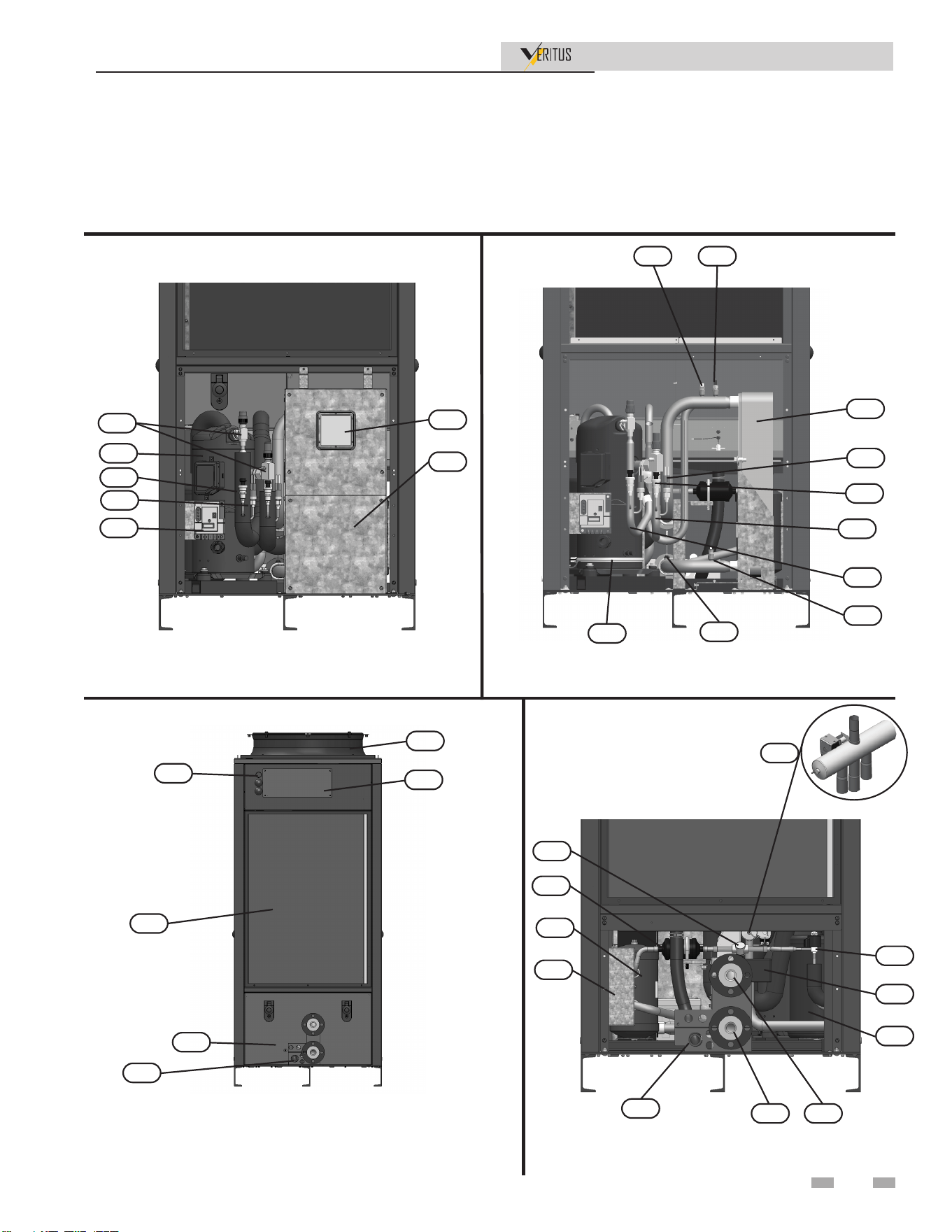
The Veritus Water Heater - How it works...
1. ScrollCompressor
The refrigerant enters the compressor through the suction line as a
low pressure vapor. The scroll compressor uses two interweaving
spirals, one stationary and one rotating to compress the vapor. The
refrigerant leaves the compressor through the discharge line as a
high pressure gas.
2. CoreSenseModule
Core Sense Module monitors and protects the compressor from
high discharge temperature and current issues. It can also alert
for refrigeration system faults.
3. 4-WayReversingValve
The 4-way valve is used to change the flow direction of the
refrigerant. During normal operation the refrigerant flows from
the compressor through the 4 way valve to the condenser, but when
controls signal the unit to go into defrost mode, the coil on the 4
way valve actuates to change flow. When actuated for defrost mode,
the valve sends refrigerant from the compressor to the evaporators.
4. Condenser
The condenser is a brazed plate double wall heat exchanger that
allows refrigerant and water flow in counter current directions to
pull heat from the refrigerant into the water.
5. ReceiverTank
The receiver tank is placed after the condenser and is used to hold
excess refrigerant at low ambient temperatures.
6. FilterDrier
The filter drier is a hermetic bi-flow filter containing check valves
that force refrigerant flow from the outside of the filter core to the
center of the filter where large contaminant particles are trapped
along with any moisture to prevent damage to the compressor.
7. SightGl ass
The sight glass is placed in the liquid line to observe when
refrigerant charge is low or moisture is in the system.
8. ElectronicExpansionValve(EEV)
The electronic expansion valve is used to regulate refrigerant flow
to the evaporators. Electronic expansion valve position is
controlled by electrical signals that cause polarity changes
between the windings inside the valve signaling the valve to move
through pulses resulting in movement in steps to open and close.
9. Evaporator
The evaporators are tube and fin type heat exchangers with
distributor heads to feed each circuit. When air is forced through
the fins, heat is absorbed from the air and transferred to the
refrigerant inside the tubes. Refrigerant enters the evaporators as a
mixture of liquid and vapor, and travels through the circuits
absorbing the heat from the air transforming into a vapor.
10. EvaporatorInletManifolds
There are two Evaporator Inlet Manifolds where refrigerant enters
the evaporator during normal operation.
11. EvaporatorOutl etManifolds
There are two Evaporator Outlet Manifolds where refrigerant
leaves the evaporator during normal operation.
12. Accumulator
An accumulator is positioned just prior to the compressor. The
purpose of an accumulator is to prevent liquid refrigerant from
entering into the compressor. Refrigerant is deposited into the tank
through a dip tube and any liquid settles in the bottom. The outlet
pulls refrigerant from the top of the tank where vapor rises.
13. WaterHeaterOutletTemperatureSensor
This sensor monitors water heater outlet water temperature.
The control module adjusts motorized ball valve and pump speed
so the outlet temperature is correct.
14. WaterOutlet
Water connection that supplies hot water to the tank.
15. WaterInlet
Water connection that returns water from the tank to the heat
pump.
16. WaterHeaterInletTemperatureSensor
This sensor monitors inlet water temperature. The control
module adjusts motorized ball valve and pump speed so the outlet
temperature is correct.
17. FlowSensor
The flow sensor is a rotary or turbine type sensor that measures
the flow rate of the inlet water, and the control module uses the
information to adjust water flow with the motorized ball valve and
variable speed pump.
18. MotorizedBallValve
The motorized ball valve regulates water flow on the outlet water
pipe.
19. ServiceValves
Service valves are located on the suction and discharge connection
of the compressor and are for isolating the compressor for service.
The ports on these valves are used to connect gauges for system
evaluation.
20. LowPressureTransducer
The low pressure transducer is tapped into the suction line to
monitor pressure of the refrigerant entering the compressor.
21. HighPressureTransducer
The high pressure transducer is tapped into the discharge line to
monitor pressure of the refrigerant leaving the compressor.
22. LowPressureSwitch
The low pressure switch is located on the suction line to trigger
the compressor to shut off if pressure goes below the minimum
recommended pressure for the compressor (5 psig).
23. HighPressureSwitch
The high pressure switch is located on the discharge line to trigger
the compressor to shut down if the refrigerant pressure exceeds the
recommended safe pressure (400 psig).
24. IndicatorLight
The indicator light illuminates when the unit is in a fault status.
25. CrankcaseHeater
The crankcase heater is mounted around the base of the compressor
to prevent the migration and condensation of refrigerant.
26. HighVoltageJunctionBox
The junction box contains the connection points for the line voltage
power, fuses, and power switch.
27. JunctionBox
Conduit connection points for pump and booster fan
connections.
28. DrainConnection
Connects the drain line to a 1" hose connection.
29. AccessPanel-FrontandRear
The front access cover provides access to the compressor and
control panel while the rear cover allow access to water lines,
junction box, and refrigerant lines from receiver tank to EEV’s.
30. InspectionWindow
The polycarbonate window that provides a view of error display on
the control board inside the control panel.
31. HighLimitSwitch
Device that monitors the outlet water temperature. If the
temperature exceeds its setting, the circuit is open, shutting the
water heater down.
32. ControlPanel
The control panel houses the heat pump control board, contactors
and relays, and 120v to 24v transformer.
33. AxialFan
The axial fan is located on top of the unit and is used to pull air
through the evaporators.
34. SuctionLine
The suction line is the pipe feeding refrigerant into the compressor.
35. Discharge Line
The discharge line is the pipe that connects to the outlet of the
compressor for refrigerant exiting the compressor.
Installation & Operation Manual
The Veritus Water Heater - How it works... (continued)
36. UnitPump
The unit pump is variable speed with feedback control to regulate
the water flow through the unit.
37. Displ ay Panel
The display panel can be mounted to the unit or in a different
location. It houses the display and the system control board.
9
Installation & Operation Manual
38. WaterManifolds
The inlet and outlet water manifolds allow for connecting multiple
units in series.
39. FlushValv es
Flush valves are on both the inlet and outlet to allow for cleaning
the condenser and the pump is also included on the inlet line.
Front View (with lower panel removed) -
Model 60K
Rear View (HEX grill removed) - Model 60K
Rear View (lower rear panel removed) - Model 60K
Front View (with lower panel & control panel
removed) - Model 60k
Model 60K
9
33
26
19
4
1
2
24
29
21
23
25
17
22
34
20
35
16
13 31
27
28
5
6
7
3
8
15 14
18
12
30
32
28
Front View (HEX grill removed) - Model 60k
Left Side (inside unit) - Model 60k
Model 60K
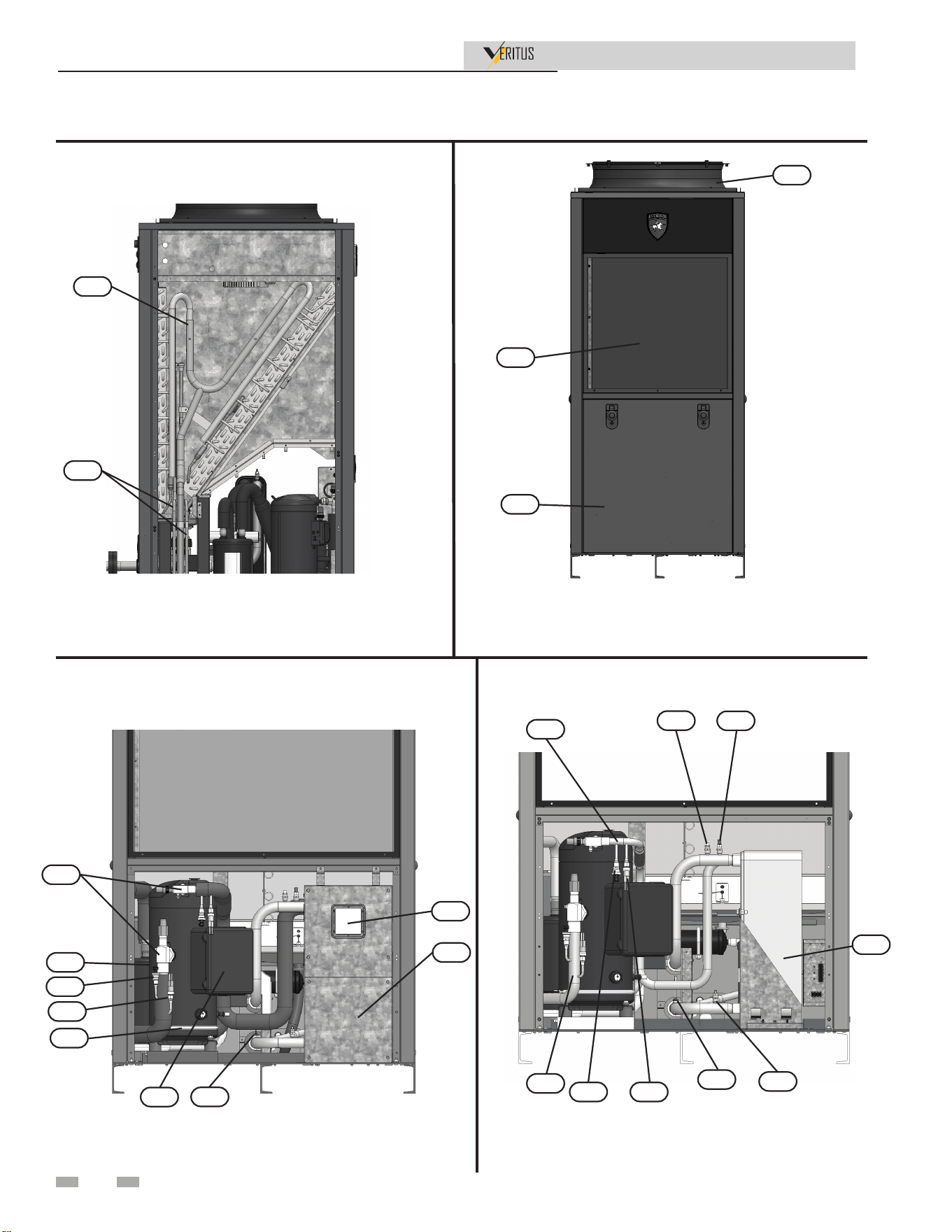
Model 140K
The Veritus Water Heater - How it works...
Installation & Operation Manual
Front View (with lower panel removed)-
Model 140K
Front View (with lower panel & control panel
removed)- Model 140k
10
11
10
9
33
29
19
1
2
17
20
22
25
30
32
4
23
34
21
35
16
17
13
31
The Veritus Water Heater - How it works... (continued)
Installation & Operation Manual
Model 140K
Rear View (HEX grill removed) - Model 140K
Rear View (lower rear panel removed) - Model 140K
Front View (HEX grill removed) - Model 140k
Left Side (inside unit) - Model 140k
11
11
10
9
33
26
28
24
29
9
33
29
27
5
6
7
3
8
15
14
18
12
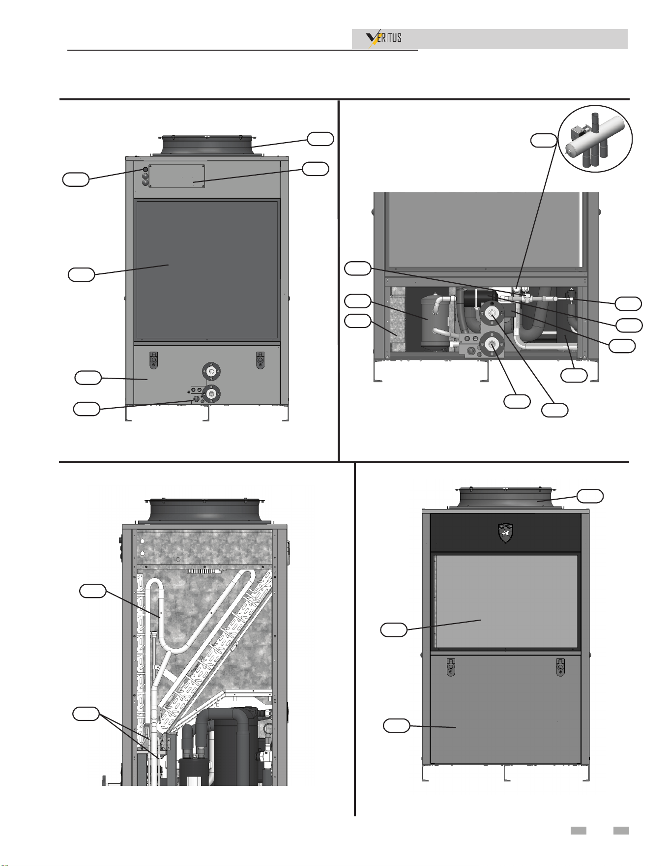
Installation & Operation Manual
Manifold
Display Box
The Veritus Water Heater - How it works...
12
With Pump Cover
Without Pump Cover
Display Panel
Inside Display Panel
39
38
36
37
The Veritus Water Heater - How it works... (continued)
13
Installation & Operation Manual
PRINCIPLE OF OPERATION
The units covered by this Instruction Manual are commercial
air to-water heat pump water heaters (HPWH).
HPWH’s remove heat from air forced through evaporators and
transfer it to refrigerant. The refrigerant is compressed which
increases temperature. The high pressure high temperature
refrigerant passes through a condenser to heat the water also
passing through the condenser.
Low temperature low pressure refrigerant gas (vapor) is drawn
out of the accumulator by the compressor. The compressor
increases the pressure and temperature of the refrigerant gas,
circulating it to the condenser again where the refrigeration
cycle starts over or continues.
THE REFRIGERATION CYCLE
Refrigerant is circulated through the refrigeration circuit
by a compressor. The refrigerant is a high temperature high
pressure gas when it leaves the compressor. Refrigerant flows
from the compressor through the 4-way valve to the condenser.
The condenser is a refrigerant-to-water heat exchanger with
two circuits. Refrigerant flows through one circuit and water
through the other. The high temperature refrigerant gas
transfers its heat to the water flowing through the condenser.
As the refrigerant gas cools inside the condenser it changes
state (condenses) from a gas to a liquid. An integrated hot
water circulator pump is provided from the factory, this pump
circulates water through the condenser.
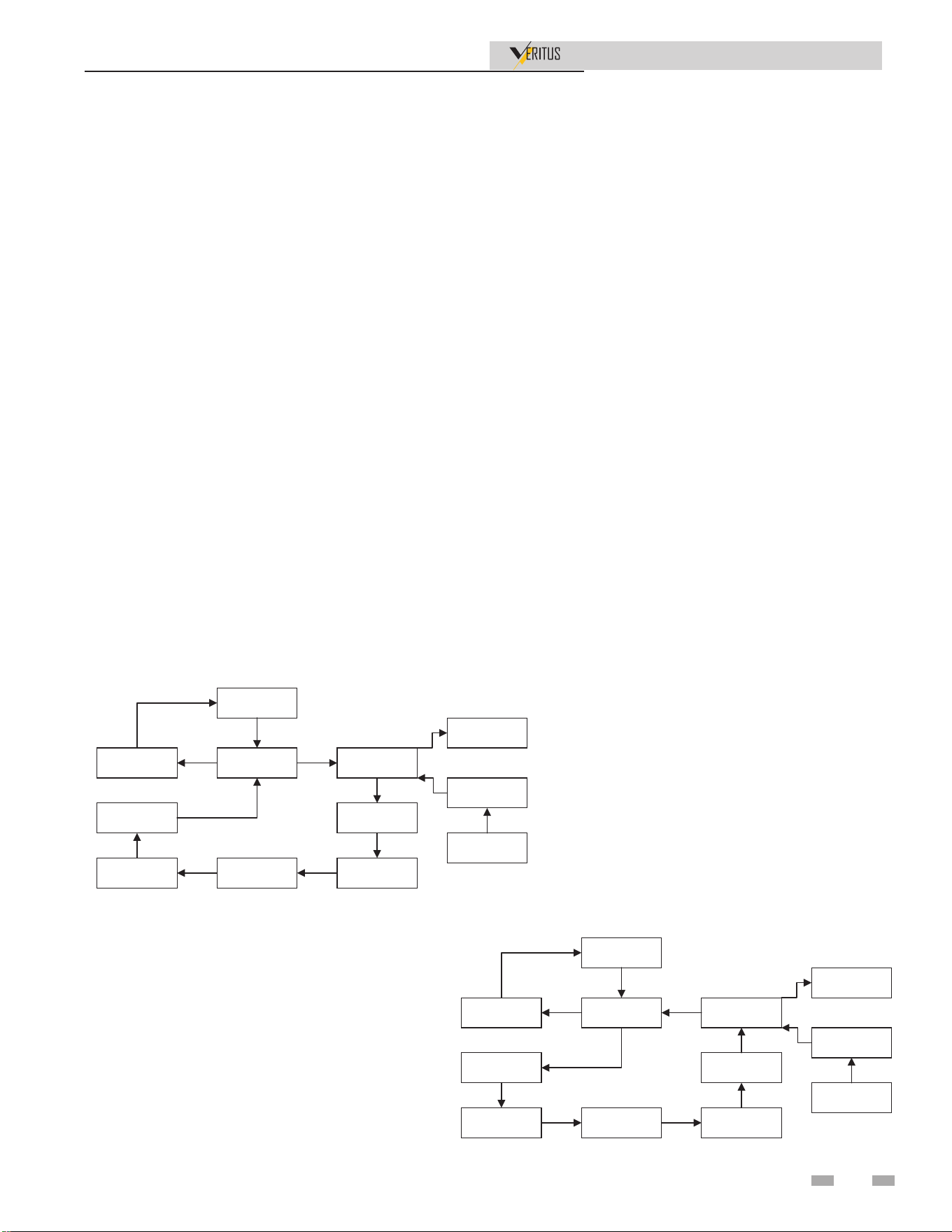
EŽƌŵĂůKƉĞƌĂƚŝŽŶ
ŽŵƉƌĞƐƐŽƌ
ĐĐƵŵƵůĂƚŽƌ
ϰtĂLJsĂůǀĞ
ŽŶĚĞŶƐĞƌ
ZĞĐĞŝǀĞƌdĂŶŬ
^ŝŐŚƚ'ůĂƐƐ
ǀĂƉŽƌĂƚŽƌƐ
&ŝůƚĞƌƌŝĞƌsƐ
KƵƚůĞƚtĂƚĞƌ
/ŶůĞƚtĂƚĞƌ
WƵŵƉ
ĞĨƌŽƐƚKƉĞƌĂƚŝŽŶ
ŽŵƉƌĞƐƐŽƌ
ĐĐƵŵƵůĂƚŽƌ
ϰtĂLJsĂůǀĞ
ŽŶĚĞŶƐĞƌ
ZĞĐĞŝǀĞƌdĂŶŬ
^ŝŐŚƚ'ůĂƐƐ
ǀĂƉŽƌĂƚŽƌƐ
&ŝůƚĞƌƌŝĞƌsƐ
KƵƚůĞƚtĂƚĞƌ
/ŶůĞƚtĂƚĞƌ
WƵŵƉ
Refrigerant leaving the condenser is a medium temperature high
pressure liquid. It flows through the liquid line to the receiver,
then the filter drier, sight glass, and finally the electronic
expansion valves (EEVs). The EEV controls the flow of the
liquid/vapor mixture which helps to ensure all of the refrigerant
is in a gaseous state by the time it exits the evaporator to protect
the compressor. The evaporator is a tube-and-fin constructed
coil. It is an air-to-refrigerant heat exchanger with refrigerant
flowing through the tubes and air flowing across the fins.
The fan moves ambient air from the installed space or air
ducted to the HPWH from another location across the fins
of the evaporator coil. The refrigerant absorbs heat from the
air in the evaporator. The refrigerant changes state (boils/
evaporates) from a liquid/vapor state back into a gas (vapor) in
the evaporator.
The refrigerant flows out of the evaporator through the line
to the 4-way valve and into the accumulator. The accumulator
traps any liquid refrigerant the evaporator is unable to vaporize
during low temperature operating conditions. The accumulator
prevents liquid refrigerant from entering the compressor where
it could damage internal components.
EŽƌŵĂůKƉĞƌĂƚŝŽŶ
ŽŵƉƌĞƐƐŽƌ
ĐĐƵŵƵůĂƚŽƌ
ϰtĂLJsĂůǀĞ
ŽŶĚĞŶƐĞƌ
ZĞĐĞŝǀĞƌdĂŶŬ
^ŝŐŚƚ'ůĂƐƐ
ǀĂƉŽƌĂƚŽƌƐ
&ŝůƚĞƌƌŝĞƌsƐ
KƵƚůĞƚtĂƚĞƌ
/ŶůĞƚtĂƚĞƌ
WƵŵƉ
ĞĨƌŽƐƚKƉĞƌĂƚŝŽŶ
ŽŵƉƌĞƐƐŽƌ
ĐĐƵŵƵůĂƚŽƌ
ϰtĂLJsĂůǀĞ
ŽŶĚĞŶƐĞƌ
ZĞĐĞŝǀĞƌdĂŶŬ
^ŝŐŚƚ'ůĂƐƐ
ǀĂƉŽƌĂƚŽƌƐ
&ŝůƚĞƌƌŝĞƌsƐ
KƵƚůĞƚtĂƚĞƌ
/ŶůĞƚtĂƚĞƌ
WƵŵƉ
WATER TEMPERATURE RANGE
The inlet/entering water temperature operating range for the
HPWH is 40°F to 140°F (4°C to 60°C). The HPWH will heat
potable water up to 160°F. When the HPWH is operating
properly the water temperature rise through the condenser
(heat exchanger) will vary based on water flow and ambient
temperatures.
REFRIGERANT CHARGE
The HPWH is factory-charged with R-513A refrigerant. The
refrigerant charge is weighed in at the factory. It should not
be necessary to add or remove refrigerant during installation,
startup, or service.
AIR TEMPERATURE RANGE
The entering air temperature operating range for the HPWH
is 23°F to 120°F (-5°C to 49°C).
When the HPWH is operating properly the air temperature
drop through the evaporator heat exchanger will be
approximately 12°F to 20°F (7°C to 12°C).
The Veritus Water Heater - How it works...
Installation & Operation Manual
14
STORAGE RECOMMENDATIONS
The HPWH units can be stored indoors or outdoors. Do not
stack units or stack other construction materials on the units
while in storage.
The HPWH units contain electrical/electronic components and
should only be stored in conditions between -20°F to 120°F
(-29°C to 49°C) and 5 to 95 percent relative humidity. Electrical
components are not moisture-tolerant.
Note: The limited warranty does not cover damage to the unit
or controls due to negligence during storage.
EQUIPMENT DISPOSAL
This heat pump water heater contains R-513A refrigerant
and is regulated as a stationary refrigeration appliance under
Section 608 of the Clean Air Act. Disposal of this unit must be
performed in accordance with the provisions in Section 608 of
the Clean Air Act and any state or local regulations that may
also apply.
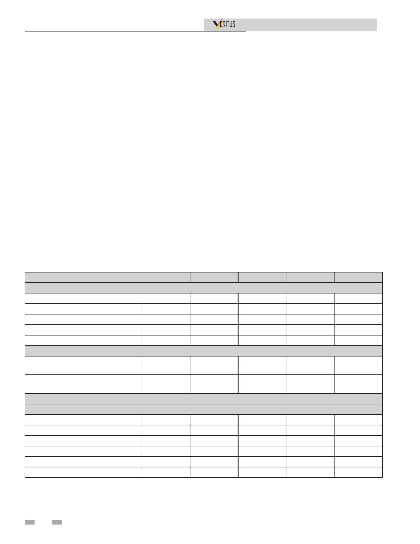
PRODUCT SUMMARY
AHP060- AHP140- AHP200- AHP280- AHP350-
PERFORMANCE
MAXIMUM OUTPUT (BTU/Hr)* 66,688 136,381 203,069 272,762 339,450
COP* 4.61 4.27 4.38 4.27 4.34
LBS.R513A 11.5 15 27 30 42
AIR VOLUME (CFM)*+ 2,335 5,102 7,437 10,205 12,539
COMPRESSOR TYPE SCROLL SCROLL SCROLL SCROLL SCROLL
WATER
HEATED WATER FLANGE
CONNECTION
1-1/2" 1-1/2" 1-1/2" 1-1/2" 1-1/2"
HEATED WATER MANIFOLD
CONNECTION
1-1/4" 1-1/4" 1-1/4" 1-1/4" 1-1/4"
ELECTRICAL
440V-480V/3PH/60HZ
SCCR 100 kA 100 kA 100 kA 100 kA 100 kA
FLA (Unit) 16.9 31.9 48.8 63.8 80.7
RLA (Compressor) 13.0 28.0 41.0 56.0 69.0
FLA (Fan and Pump) 3.9 3.9 7.8 7.8 11.7
MCA 20.2 38.9 59.1 77.8 97.8
MOCP 35 70 100 150 175
The Veritus Water Heater - How it works...
Installation & Operation Manual
Legend
COP: Coefficient of Performance
SCCR: Short-Circuit Current Rating
FLA: Full Load Amps
RLA: Rated Load Amps
MCA: Minimum Circuit Ampacity
MOCP: Maximum Overcurrent Protection
Notes:
• All models listed requires a system control panel (priced & packaged
separately)
• Available in 208v or 440-480v from factory. Must denote on submittal.
• Models AHP200-350:
• multiple modules (packaged separately)
• includes manifold piping assembly (packaged separately)
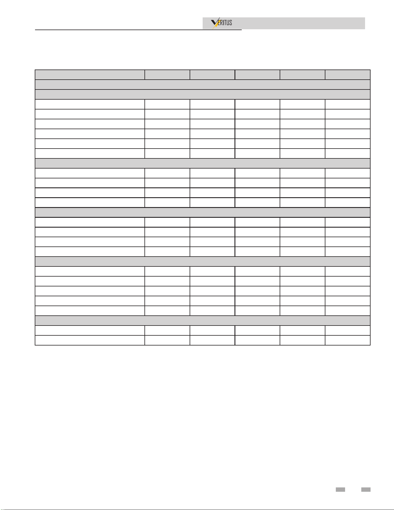
PRODUCT SUMMARY continued
AHP060- AHP140- AHP200- AHP280- AHP350-
ELECTRICAL
208V/3PH/60HZ
SCCR 100 kA 100 kA 100 kA 100 kA 100 kA
FLA (Unit) 32.5 53.4 85.9 106.8 139.3
RLA (Compressor) 26.5 47.4 73.9 94.8 121.3
FLA (Fan and Pump) 9.0 9.0 18.0 18.0 27.0
MCA 39.1 65.3 104.4 130.6 169.7
MOCP 65.6 112.7 175 225 275
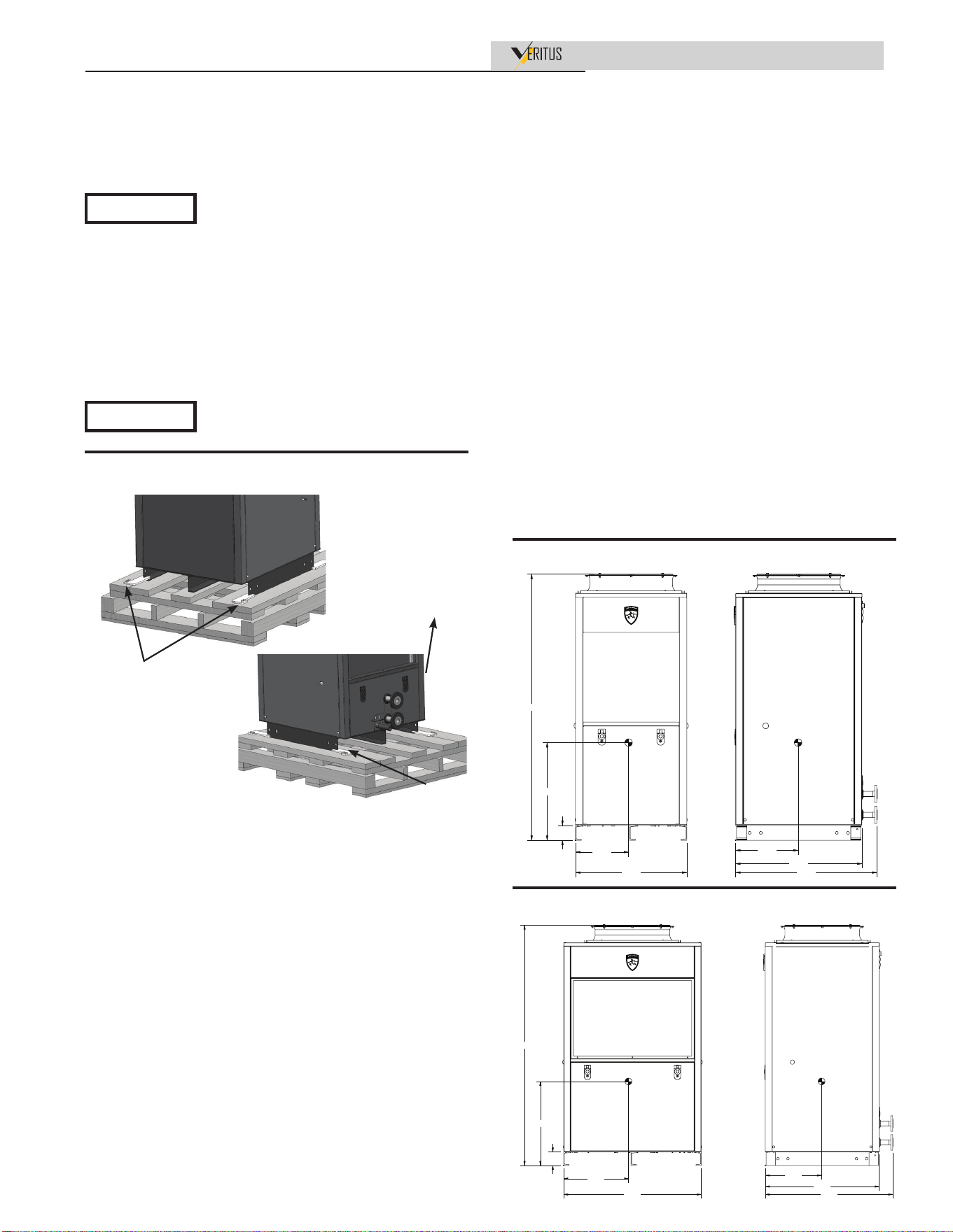
DIMENSIONS (Product)
HEIGHT 71-3/4" 71-3/4" 71-3/4" 71-3/4" 71-3/4"
WIDTH 30-5/8" 41-5/8" 72-1/4" 83-1/4" 113-7/8"
DEPTH 38-1/2" 38-1/2" 38-1/2" 38-1/2" 38-1/2"
OPERATING WEIGHT (LBS) 743 913 1,638 1,809 2,533
DIMENSIONS (Shipping)
HEIGHT 87-1/4" 87-1/4" 87-1/4" 87-1/4" 87-1/4"
WIDTH 43" 54" 97" 108" 151"
DEPTH 54" 54" 54" 54" 54"
SHIPPING WEIGHT (LBS) 1,155 1,370 2,505 2,721 3,854
SERVICE CLEARANCES
FRONT 36" 36" 36" 36" 36"
REAR 36" 36" 36" 36" 36"
RIGHT SIDE 0" 0" 0" 0" 0"
LEFT SIDE 0" 0" 0" 0" 0"
TOP 48" 48" 48" 48" 48"
FAN SOUND STANDARD RATING (dBA)**
AMBIENT OF 80° F 58 64 65 67 68
AMBIENT OF 23° F 70 72 74 75 76
*DOE test standard, 80° F ambient with 63% humidity, inlet water temperature at 70° F; outlet water temperature at 120° F.
** Average of sound measured 3’ from ground; 10’ all sides including top.
+ For additional CFM requirements, reference sizing guides.
15
Performance
Installation & Operation Manual
Model
Number
Water Flow Rate
in GPM (Single
Pass)
Performance²
Air Volume
(CFM)
Water
Connection
Heating Capacity
BTU/hr
COPh
AHP060 2.69 66,688 4.6 1543.95 1-1/2 NPT
AHP140 5.22 136,381 4.3 5102.25 1-1/2 NPT
AHP2001 7.91 203,069 4.4 6646.20 1-1/2 NPT
AHP2801 10.44 272,762 4.3 10204.50 1-1/2 NPT
AHP3501 13.13 339,450 4.3 11748.45 1-1/2 NPT
Desired Model
Performance
Combination of Models
AHP200 AHP060 + AHP140
AHP280 AHP140 x 2
AHP350 AHP140 x 2 +AHP060
NOTES:
1. Models 200 through 350 are composed of combinations of models 60 and 140 which are the certied units.
2. Performance rated at 80.6°F ambient temperature with 63% relative humidity; Inlet water at 70°+ 1°F, Outlet water at 120°F +
5°F.
3. Supply Voltage - 208V/3-phase 60 Hz (AHP060-208 and AHP140-208 models)
480V/3-phase 60 Hz (AHP060-480 and AHP140-480 models)
4. Variable fan speed across dierent ambient temperatures.
e table above lists performance information on 5 unit sizes. ese
sizes are based on combinations of the 2 base models, AHP060 and
AHP140. e table below shows the combination of models needed
to get the desired model performance.
Maximum allowed working pressure
on a refrigeration circuit:
High side - 347 psi
Low side - 61 psi
Maximum water pressure - 175 psi
e heat pump water heaters are
intended for use at altitudes of 6,562
feet (2000 meters) and below.
NOTICE
NOTICE
When servicing this unit, verify the power to the unit is turned off prior to opening the control cabinet door.
LOW LEAD CONTENT
16
1 Determine Water Heater Location
Installation & Operation Manual
Installation must comply with:
• Local, state, provincial, and national codes, laws, regulations,
and ordinances.
• National Electrical Code.
• For Canada only: B149.1 Installation Code, CSA C22.1
Canadian Electrical Code Part 1 and any local codes.
Costs to diagnose, perform service, and repair damage caused
by installation errors are not covered under the limited warranty.
Costs to correct installation errors are not covered under the
limited warranty. Before locating the water heater, check:
1. Check for nearby connection to:
• Water piping
• Ducting Options
• Electrical Power
2. Locate the appliance so that if water connections should
leak, water damage will not occur. When such locations
cannot be avoided, it is recommended that a suitable drain
pan, adequately drained, be installed under the appliance.
Under no circumstances is the manufacturer to be held
responsible for water damage in connection with this
appliance, or any of its components.
3. Check area around the water heater. Remove any corrosive
materials.
4. If a new water heater will replace an existing water heater,
check for and correct system problems, such as system
leaks causing oxygen corrosion or heat exchanger cracks
from hard water deposits.
e Veritus water heater meets safety test
requirements under UL-60335-2-40 – latest
edition.
NOTICE
Read all installation requirements in
this manual before installation begins.
5. Check around the water heater for any potential air
contaminants that could risk corrosion to the water
heater (see Table 1-3 on page 17). Remove any of these
contaminants from the water heater area.
DO NOT install units in rooms or environments that
contain corrosive contaminants. Failure to comply could
result in severe personal injury, death, or substantial
property damage.
Indoor/Outdoor Installations
(Milder Climates)
Choose a location for optimal performance and safety.
The HPWH should be located in an area where leakage from
the HPWH or system will not result in property damage.
Freezing temperatures
The HPWH unit can be installed in space where freezing
temperature will occur, and is programmed to cycle the pump
to keep water flowing. Heat tape is also installed on the drain
pan, condenser, and water inlet and requires power to the unit.
Damage caused by exposure to freezing temperatures is not
covered under the limited warranty.
Coastal regions
The exterior materials and components supplied on the
HPWH have been tested, and passed the requirements for UL
60335-2-40.
Indoor
When installed indoors it may be necessary to duct HPWH
outlet air out of the space to prevent over cooling of the room
which will prevent optimal performance of the water heater.
Ducting air into the water heater may be necessary to maintain
a sufficient air supply to run the unit.
Heat source
The HPWH unit should be located where there is an adequate
source of ambient heat and where the cooling benefit can
be utilized when possible. If installation in a space with an
adequate heat source is not possible the HPWH unit can be
ducted to/from another space such as a boiler room or to the
outdoors where sufficient heat is available.
17
1 Determine Water Heater Location (continued)
18
Installation & Operation Manual
Multiple appliances can be installed side by
side with no clearances between adjacent
appliances because the appliances are
approved for zero clearances; however,
service access will be limited from the sides.
Consult with the local inspection authority
for approval.
NOTICE
If you do not provide the recommended
service clearances shown, it may not be
possible to service the appliance without
removing it from the space. ese
clearances are also needed for adequate air
ow.
NOTICE
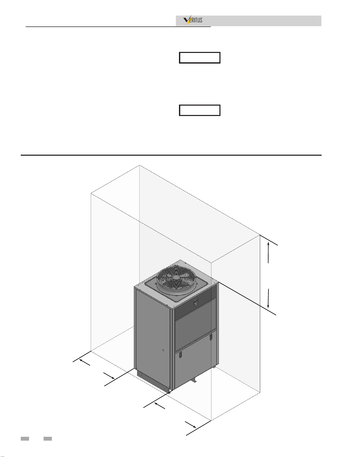
Clearances:
1. Recommended clearances for service access, ducting or
air flow from the top of the unit is 48 inches.
2. To ensure optimal performance a minimum of 36 inches
clearances required from the back, and front of the
HPWH unit and any wall obstruction. When installed
on an equipment pad the HPWH must be level.
Front / Rear ............................................................................... 36"
Top .............................................................................................. 48"
Figure 1-1 Minimum Required Clearances
TOP
48"
FRONT
36"
REAR
36"
1 Determine Water Heater Location
Installation & Operation Manual
19
Provide air openings to room:
Veritus water heater alone in equipment
room
Conditioned space
When installed in a conditioned space ducting supply
(outlet) air to an alternate location may be necessary to avoid
overcooling of the space where the HPWH is installed or
provide spot cooling in areas for comfort and/or to offset
cooling load. See Air Flow and Ducting starting on page 39.
Unconditioned space
When installed in an unconditioned space ducting return
(inlet) air from an alternate location may be necessary to access
an adequate or greater source of heat for optimal efficiency. See
Air Flow and Ducting starting on page 39.
Air Temperature
Entering air temperature
The return (entering) air temperature range of operation for
the unit is 23° - 120°F (-5°C to 49°C). The air temperature drop
(Delta T - ΔT) through the evaporator (heat exchanger) will be
approximately 12°F to 20°F (7°C to 12°C).
If the entering air temperature is outside this operating range
the HPWH unit discontinues heating operation until the
entering air temperature returns to this operating range.
Flooring and foundation:
Flooring
The Veritus HP is approved for installation on floors that are
level and structurally sound to support the weight of the unit.
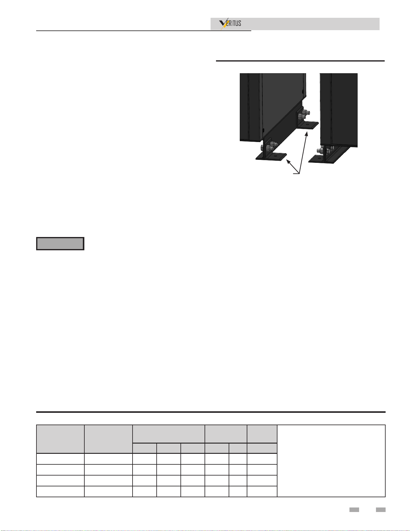
Seismic bracing
For installations requiring seismic bracing, the base legs of
the appliance are designed to allow for the use of mounting
brackets to meet seismic requirements. The seismic brackets
shown in Figure 1-2 are available in a separate kit. The units
must be spaced a minimum distance apart to allow for spacing
between the anchors (not shown). Consult the factory for more
information on anchor and spacing requirements.
Vent and air ducts
The Veritus water heater requires a special vent system,
designed for pressurized venting. Consult the factory.
⚠WARNING
Do not install the water heater on carpeting
even if foundation is used. Fire can result,
causing severe personal injury, death, or
substantial property damage.
If flooding is possible, elevate the water heater sufficiently to
prevent water from reaching the water heater.
Model
Volts/Phase/
Hz
COMPRESSOR
FAN
MOTOR
PUMP
RLA: Rated Load Amps
FLA: Full Load Amps
HP: Horse Power
MCC: Maximum Continuous Current
All shown MFS Values are rounded
up to the nearest common fuse size.
RLA MCC HP FLA HP FLA
AHP060-480 440-480/3/60 13.0 14.2 6.0 2.5 2.0 1.4
AHP140-480 440-480/3/60 28.0 35.0 13.0 2.5 2.0 1.4
AHP060-208 208/3/60 26.5 31.5 6.0 4.6 2.0 1.4
AHP140-208 208/3/60 47.4 74.0 13.0 4.6 2.0 1.4
Table 1-1 Voltage & Amperage Ratings (single units)
Figure 1-2 Seismic brackets
Electrical requirements
Ensure the power supply voltage and phase at the job site
matches the power supply ratings listed on the HPWH data
rating label BEFORE INSTALLATION BEGINS.
The installation must conform with these instructions and the
local code authority having jurisdiction and the requirements
of the power company. In the absence of local codes, the
installation must comply with the current editions of the
National Electrical Code, ANSI/NFPA 70 or the Canadian
Electrical Code CSA C22.1.
Voltage applied to the HPWH should not vary more than +6%
to -6% of the voltage requirement listed on the HPWH rating
label for satisfactory operation.
Fuses supplied with the unit and tested are time delay fuses.
2000813057 00
SEISMIC
BRACKETS
1 Determine Water Heater Location (continued)
Installation & Operation Manual
Model Volts/Phase/Hz FLA
AHP060-208 208/3/60 32.5
AHP140-208 208/3/60 53.4
AHP200-208 208/3/60 SEE NOTE
AHP280-208 208/3/60 SEE NOTE
AHP350-208 208/3/60 SEE NOTE
AHP060-480 440-480/3/60 16.9
AHP140-480 440-480/3/60 31.9
AHP200-480 440-480/3/60 SEE NOTE
AHP280-480 440-480/3/60 SEE NOTE
AHP350-480 440-480/3/60 SEE NOTE
Table 1-2 Voltage & Amperage Ratings
Minimum Wire Size
Allowable Ampacities of Insulated Conductors
Three-phase heaters are three wire circuits. In addition to the
foregoing, a grounded conductor is required. Not more than
three conductors in raceway, cable, or earth (directly buried),
based on ambient temperature of 30°C (86°F).
Minimum circuit ampacity & maximum fuse size
Use MCA to select the minimum field wires size to power the
unit and MFS to select the maximum fuse size for over current
protection as follows:
MCA = C x 1.25 + M + P
MFS = C x 2.25 + M + P
Where:
C - Compressor RLA
M - Blower Motor FLA
P - Pump FLA
Products to avoid:
Spray cans containing chloro/fluorocarbons
Permanent wave solutions
Chlorinated waxes/cleaners
Chlorine-based swimming pool chemicals
Calcium chloride used for thawing
Sodium chloride used for water softening
Refrigerant leaks
Paint or varnish removers
Hydrochloric acid/muriatic acid
Cements and glues
Antistatic fabric softeners used in clothes dryers
Chlorine-type bleaches, detergents, and cleaning solvents
found in household laundry rooms
Adhesives used to fasten building products and other similar
products
Areas likely to have contaminants
Dry cleaning/laundry areas and establishments
Swimming pools
Metal fabrication plants
Beauty shops
Refrigeration repair shops
Photo processing plants
Auto body shops
Plastic manufacturing plants
Furniture refinishing areas and establishments
New building construction
Remodeling areas
Garages with workshops
Table 1-3 Corrosive Contaminants and Sources
NOTE: Total amperage is for units consisting of more than
one base unit and therefore multiple connection points are
to be calculated from base units AHP060 and AHP140 in
combinations listed on page 15.
20
Installation & Operation Manual
2 Prepare water heater
1. After removing the outer shipping carton from the water
heater, remove the parts box.
2. To remove the water heater from the pallet remove the
four (4) lag bolts located at the front and rear of the unit
(FIG. 2-1).
Remove water heater from wood
pallet
Storage & Handling
The heat pump water heaters covered in this manual are
stationary refrigeration appliances. Careful handling is
necessary to prevent internal damage.
1. Do not tilt the unit more than 45 degrees in any direction
from the vertical position. All internal components are
braced from the base of the unit. Tilting may compromise
the refrigeration piping inside the unit and cause
refrigerant leaks.
2. Do not remove the cover or deface any permanent
instructions, wiring diagrams, labels, or the rating label
for the outside cabinet or inside panels on the HPWH
unit.
3. Do not hoist the unit with chains or straps unless spreader
bars are furnished. The side panels and top of the unit are
not constructed to handle significant force from the sides
or above. Failure to use spreader bars when lifting can
cause damage to the unit.
Do not drop the water heater or bump the
jacket on the floor or pallet. Damage to
the water heater can result.
Models containing combinations of the
2 base unit sizes (AHP060 and AHP140)
are shipped as individual AHP60 and
AHP140 units on separate pallets. This
applies to the AHP200, AHP280 and the
AHP350.
Figure 2-1 Water heater mounted on shipping pallet
Figure 2-2 Center of gravity for 60k heat pump
Figure 2-3Center of gravity for 140k heat pump
NOTICE
NOTICE
4. When lifting the heat pump with a crane, use appropriate
straps and rigging. Lifting straps should be long enough
that the angle between the strap and unit is no less than
45 degrees (see figure 2-5). Lifting from another location
could result in deformation and failure of sheet metal
structure.
5. The HPWH unit is heaviest on the compressor side (left
side when facing the front of the unit). The weight of an
AHP140 is 847 lbs. and the weight of an AHP60 is 671
lbs. See Figures 2-2 and 2-3 for unit dimensions and
approximate location of the center of mass.
6. Before lifting or moving the heat pump with a forklift,
remove the front and rear jacket panels to avoid damage
to the panel tabs When using a forklift to raise the HPWH
unit ensure the forks are positioned correctly between the
runners on the bottom of the HPWH unit. See Figure 2-6.
7. The HPWH unit must be lifted from the front side only
when using a forklift to raise the unit. See Figure 2-6.
Front
Back
LAG BOLTS
(QTY. 2)
LAG BOLTS
(QTY. 2)
Hardware is provided to bolt all for corners of the units
together, as shown in Figure 2-7.
Installation & Operation Manual
Figure 2-4 Remove lower front and rear panels before
lifting unit
Figure 2-6 Water heater and forklift fork position
Figure 2-7 Modular unit base assembly (not required)
Figure 2-5 Appropriate lifting strap angles
2 Prepare water heater (continued)
Assemble water manifold
The inlet and outlet manifolds are located in the parts box
along with the mounting bracket and hardware. Figure 2-9
shows the manifold assembled and connected to the base.
Figure 2-9 Single Manifold Assembly
Figure 2-10 Multi-Manifold Assembly
)52175($53$1(/7$%6
Figure 2-8 Manifold parts received in kit
0,1
6,'(
HARDWARE
PROVIDED
2000838648 00
22

Installation & Operation Manual
3 Installing water heater
Required Ability
Installation and service of the HPWH unit requires ability
equivalent to that of a qualified agency in the field involved.
Plumbing, ducting and electrical work are required.
See Installer Qualifications on page 6.
General
The installation must conform with these instructions and the
local code authority having jurisdiction. In the absence of local
codes, the installation must comply with the latest editions of
the National Electrical Code, ANSI/NFPA 70 or the Canadian
Electrical Code CSA C22.1. The National Electrical Code
may be ordered from: National Fire Protection Association,
1 Batterymarch Park, Quincy, MA 02269. The Canadian
Electrical Code is available from the Canadian Standards
Association, 8501 East Pleasant Valley Road, Cleveland, OH
44131.
DO NOT start the HPWH unit or test the electrical system
before it is connected to the water system, purged of air and
filled with water. See Start Up on page 50.
See pages 8-12 to identify the principal components of the
HPWH.
Unit Placement
Whether replacing existing water heating equipment or
installing the HPWH in new construction, the following critical
points must be observed. The HPWH unit:
1. Should be installed near a floor drain for condensate
removal.
2. The HPWH, storage tank and water heater(s) should be
located in an area where leakage will not result in damage
to adjacent area or to lower floors in the building structure.
3. The HPWH unit must be level for proper condensate
drainage. Shim the channel type skid base, pad or floor as
necessary if leveling is required.
4. Should be installed close to the point of major hot water
usage and power supply.
5. Should be located so that hot water piping and branch
circuit wiring will be as short as possible.
Mounting Frame
The mounting frame must support the length, width, and
weight of the HPWH unit. The weight of the HPWH unit must
be evenly dispersed across the footing channels on the bottom
of the unit.
NOTE: A qualified engineer should design and size the
structural components of the mounting frame. Structural
channels in a field-provided frame should be mounted in line
with each of the unit base channels.
Required Tools & Materials
Installation & Start-up Tools
1. All tools common to installation and service of commercial
electric water heaters such as hand tools, pipe cutter and
torch.
2. Heat transfer compound (paste).
3. Electrical switch lock out device - used to secure disconnect
switches/breaker panels while servicing.
4. Electronic thermometer including:
• Four (4) thermocouple sensors capable of measuring
surface temperatures on water or refrigerant piping up to
2 inch diameter.
• Two (2) thermocouple sensors capable of measuring
ambient air temperature.
• Temperature range 32°F - 210°F (0°C - 100°C).
5. Volt-Ohm Multi Meter - capable of measuring:
• AC Voltage up to 600 VAC.
• DC Voltage up to 24 VDC.
• Ohms up to 2,000,000 ohms.
• Continuity.
6. AC amp meter - capable of measuring:
• AC amperage up to 200 amps.
7. Calculator.
Service Tools
See Installer Qualifications on page 6 regarding regulations and
certifications required under Section 608 of the Clean Air Act
before servicing the refrigeration circuit.
Pad Mounting
The HPWH may be pad mounted. Vibration isolator mounts
MUST BE placed between the unit and the equipment pad to
prevent mechanical vibration transmitting into the building
structure. Selection of appropriate vibration isolators should be
made by a qualified engineer. Unit must be level.
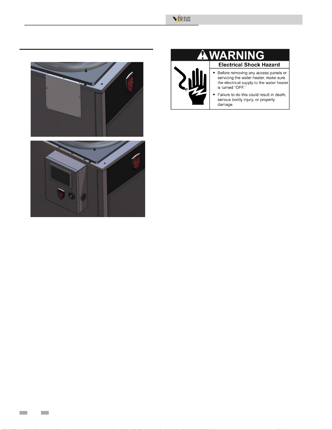
Display Panel Mounting
The display panel can be mounted to either side of the unit or
in an equipment room that is no more than 1,500 feet away
from the heat pump.
To mount the display to the side of the unit, the unit mounting
bracket should be fastened to top of the unit using the screws
provided. The bracket should be located one inch away from
the center of the plugged hole on top of the unit. Once the
bracket is attached, there are four holes on the back panel of
the box. Fasten the four sheet metal screws provided through
the back, bracket, and side panel to secure the display panel in
place.
1. Refrigeration manifold gauges.
2. Refrigeration charging scale.
3. Refrigeration vacuum pump.
4. Refrigerant recovery machine.
5. Refrigerant reclamation storage tank.
23
Installation & Operation Manual
3 Installing water heater (continued)
Water Connections
Water piping must be installed in accordance with the
instructions in this manual and all local plumbing codes having
jurisdiction. See Piping Diagrams on pages 30-38 as a reference
for these instructions.
Installation Instructions
1. This HPWH unit is not designed to supply hot water
directly to hot water fixtures. The HPWH unit must be
installed with separate storage tanks as shown in the water
piping diagrams in this manual.
2. Water lines installed between the storage tank and the
HPWH unit MUST NOT be less than the water pipe
connection sizes on the unit. See Figures 4-2 thru 4-10 on
pages 30-38.
3. The HPWH should be plumbed directly to the storage
tanks.
4. The cold water supply can be connected into the heat
pump inlet manifold or lowest tank connection.
5. The outlet (supply) water from the HPWH unit should
connect to the inlet connection on the storage tank, and
should be located above the inlet connection.
6. The inlet (return) water entering the HPWH should
connect to the inlet connection on the storage tank lower
than the tank outlet connection.
7. A T&P valve must be installed in the designated opening on
the storage tank per the tank manufacturer’s requirements.
See Temperature - Pressure Relief Valve on page 27.
8. For optimal performance minimize the equivalent length
of water piping between the HPWH and storage tank.
9. Building hot water recirculation loop should be connected
to the inlet of the backup water heater on two tank
preheat configurations or to the storage tank on single
tank configurations. The recirculating pump MUST BE
controlled by a field supplied thermostat installed in the
building recirculation return line near the storage tank
or back up heater. The thermostat should stop pump
operation the moment the recirculation line is hot.
Electrical Connections
Correct Voltage and Phase
Ensure the power supply voltage and phase at the job site
matches the power supply ratings listed on the HPWH rating
label BEFORE INSTALLATION BEGINS.
Voltage applied to the HPWH should not vary more than +6%
to -6% of the voltage requirement listed on the HPWH rating
label for satisfactory operation.
Energizing the HPWH with the wrong voltage and/or phase
may cause permanent damage to HPWH components. Damage
resulting from applying the wrong power supply voltage or
phase to the HPWH is not covered under the limited warranty.
Branch Circuit Disconnect Switch
The power supply wiring and equipment grounding must be
installed in accordance with local codes or, in the absence of
local codes, the National Electrical Code, ANSI/ NFPA 70 or
the Canadian Electrical Code, CSA C22.1.
Install an adequately fused disconnect switch as close to the
units as possible. See unit rating label for maximum fuse size
(MFS).
Run the power supply lines from the disconnect to the control
box at the top back panel of the unit. Connect the lines to the
terminals on input side of power distribution block L1, L2 & L3
for three phases. Connect ground wire to ground lug. If out of
phase the HPWH will shut down and display error.
Figure 3-1 Display Panel Mounting on the Unit
24
3 Installing water heater
Installation & Operation Manual
Single Tank Configuration
The HPWH must be plumbed to storage tank. The maximum
stored water temperature the HPWH unit can produce in the
storage tank is 160°F (71°C). Tank ports must be large enough
to handle the peak water flow rates through the water heating
system. See Piping Diagrams on pages 30-38 for detailed piping
diagrams.
Standard Tank Thermostat
Standard tank thermostats already installed in the storage tank
may be used. Ensure the standard tank thermostat is installed
the lower third of the tank. Wire the existing tank thermostat
to the system control board.
Multiple Tank Pre-heat Configuration
When water temperatures above 160°F (71°C) are required the
HPWH and storage tank are piped in series (upstream) with a
backup water heater. See Water Temperature on page 14. The
backup water heater will raise the temperature of the preheated
water to the final system temperature required.
Figure 3-2 Condensate trap
Water Temperature
Maximum System Temperature
The HPWH units covered in this manual are capable of
maintaining a maximum system/storage tank temperature of
160°F (71°C). Some commercial water heating applications
may require higher temperatures. Install a booster water heater
downstream from the storage tank for temperatures above
160°F (71°C).
Inlet & Outlet Water Temperature
The inlet (entering) water temperature operating range for the
HPWH is 40°F to 140°F (4°C to 60°C). The water temperature
rise (Delta T - ΔT) through the condenser (heat exchanger) will
vary dependent on water flow and ambient temperature from
8°F to 120°F (5°C to 75°C).
Outlet water temperatures up to 160°F (71°C) are possible
during normal operation. Exposure to water temperatures
this high can cause serious bodily injury or death. See Mixing
Valves and Table 4-1 on page 27.
Service & Installation Notes:
If the inlet (entering) water temperature is outside the operating
temperature range for extended periods the control system
may lock out on high or low refrigerant pressure switch events/
trips.
When the control system locks out on a refrigerant pressure
switch event, the compressor and fan will stop running. The
pump will be powered but may not run. For the high pressure
switch, this is a hard lock out condition. For the low pressure
switch, this is an auto-reset lockout. The control system is
manually reset by cycling power to the HPWH off and then on
again or by pressing the button on the side of the control panel.
The tank thermostat must not be set any higher than 160°F
(71°C) to prevent control system lock outs.
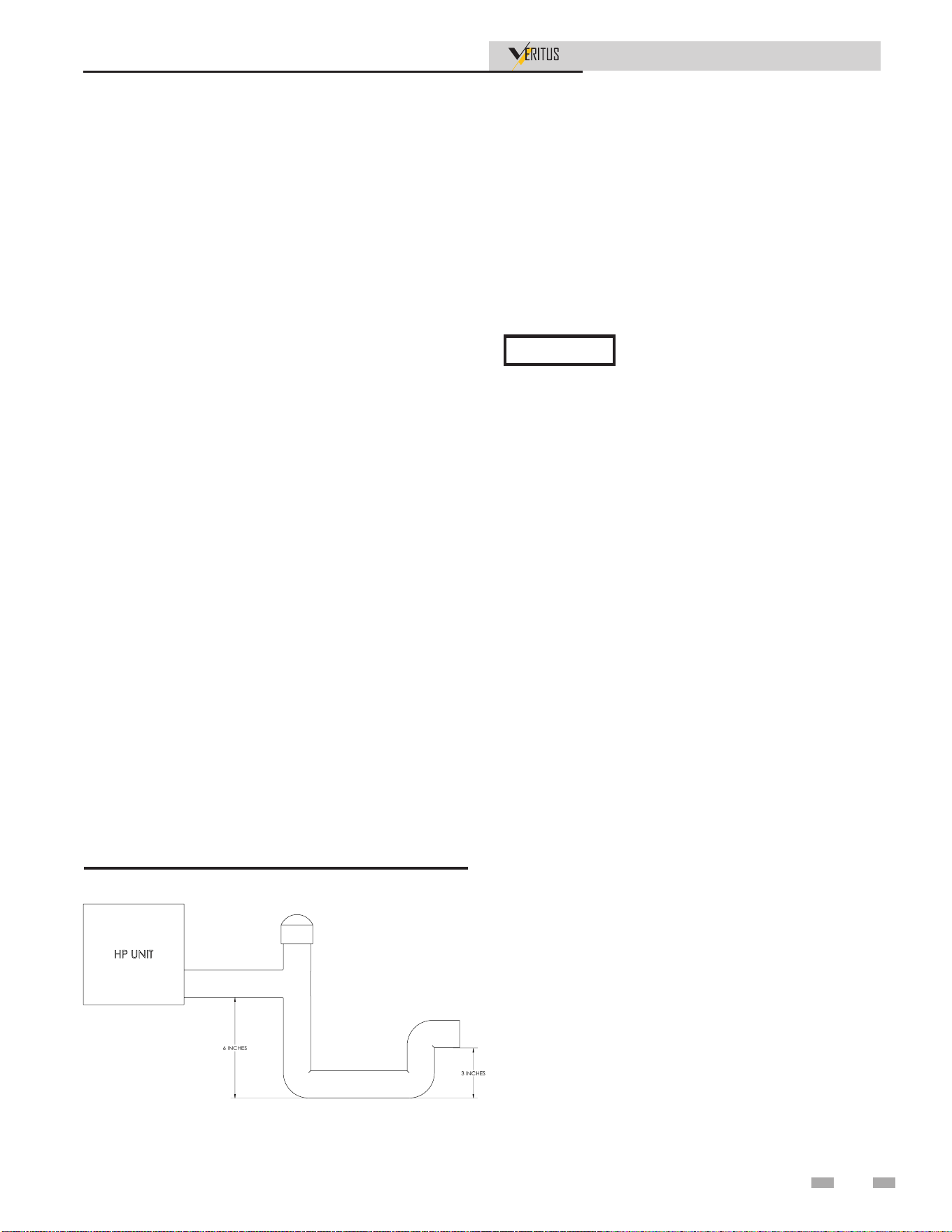
Condensate Drain Line
The HPWH unit must be plumbed to permit condensate
drainage. Drain piping connected to the HPWH unit should
be a minimum 1 inch PVC or equivalent. A condensate trap
must be used to overcome the internal vacuum to permit
proper drainage. See Figure 3-2 for recommended drain trap
dimensions.
The condensate must be discharged to a suitable drain. If a
drain is inaccessible, use a condensate pump.
Drain trap must be ooded to prevent water
from backing up into the drain pan
NOTICE
10. Do not use check valves between the heat pump outlet
and tank unless required by code on the system diagrams.
Internal ball valves can prevent hot water short circuiting.
11. Water lines shared by parallel HPWH units must be
large enough to handle combined water flows. Flow rates
through the heat pumps and tank(s) must be balanced.
12. All components in the hot water supply system must be
adequately sized to meet peak water flow requirement.
13. When the HPWH unit is installed above the storage tank
install a tee fitting at a high point in the outlet water line
leaving the unit. Install a purge valve, or if required by
local code, a T&P valve (temperature and pressure relief)
in a branch of the tee fitting that can be used to purge air
from the HPWH unit during start up.
14. DO NOT install a (T&P) relief valve in the outlet line of
the HPWH unit unless required by local code.
15. Dielectric unions should be installed at the inlet and outlet
water lines to the HPWH unit.
16. All HPWH water piping must be insulated.
2000668992 00
25
Installation & Operation Manual
26
4 System Piping
Read all installation requirements in this manual before
installation begins.
The water piping installation must conform to these instructions
and to all local and national code authority having jurisdiction.
Costs to diagnose, perform service and repair damage caused
by installation errors are not covered under the limited
warranty.
Costs to correct installation errors are not covered under the
limited warranty.
System water piping methods
Observe a minimum of 1/4 inch clearance around all
un-insulated hot water pipes when openings around the pipes
are not protected by non-combustible materials.
Water connections
The inlet and outlet water connections on the AHP60- AHP140
are 1-1/4 flange, but the manifolds provided are 1-1/2 NPT.
Cold Water Supply
Cold water supply lines should be connected directly to the
HPWH inlet or T fitted into the inlet (return) water piping.
Water Pressure
System water pressure should be maintained above 12 PSI.
Local code may require, and the manufacturer recommends,
installing a pressure reducing valve (PRV) in the cold water
supply to the building to maintain consistent water pressure.
Closed Water Systems
Water supply systems may, because of code requirements or
such conditions as high line pressure, among others, have
installed devices such as pressure reducing valves, check valves,
and back flow preventers. Devices such as these cause the water
system to be a closed system.
Heating of high hardness and/or high total dissolved solids
water is not recommended for the circulating pump based on
the water chemistry of the water to be heated. See Table 9-1 in
Start-up Section for recommendations.
Water with a hardness of less than 5 grains per gallon will
usually have a pH which can be aggressive and corrosive
causing non-warrantable damage to the pump, and associated
piping. Corrosion due to water chemistry generally shows up
first in the hot water system because heated water increases the
rate of corrosive chemical reactions.
Condensate Removal
The HPWH unit produces condensate which must be
discharged. If there is no drain easily accessible, a condensate
lift pump must be installed to discharge the condensate to a
remote location. See Condensate Drain Line on page 25 for
installation instructions.
Water Chemistry
General Piping Information
Basic steps are listed below along with illustrations on the
following pages (FIG. 4-2 thru 4-10), which will guide you
through the installation of the Veritus water heater.
1. Connect the manifold mounting bracket to the back of
the unit.
2. Connect the inlet manifold to the inlet side of the water
heater with pump connected.
3. Connect the outlet manifold to the outlet side of the water
heater.
4. Connect the cold water supply to the inlet side of the water
heater.
5. Connect the hot water supply to the outlet side of the
water heater.
6. Install a back flow preventer on the cold feed makeup
water line.
7. Install an expansion tank on the system supply. Consult the
tank manufacturer’s instruction for specific information
relating to tank installation. Size the expansion tank for
the required system volume and capacity.
8. Install a drain valve at the lowest point of the system.
9. Install field supplied relief valve to the water outlet in
accordance with ASME Boiler and Pressure Vessel Code.
Pipe the discharge of the safety relief valve to a suitable
drain to prevent injury in the event of pressure relief.
Provide piping that is the same size as the safety relief valve
outlet. Never block the outlet of the safety relief valve.
See the piping illustrations included in this section, Figures 4-2
thru 4-10, for suggested guidelines in piping the Veritus water
heater.
*Please note that these illustrations are
meant to show system piping concept only,
When connecting the unit to piping made
of a different material, use of a dielectric
NOTICE
NOTICE
Contaminated Water
This HPWH unit must not be used to heat any fluid other than
water. Corrosive chemicals must not be introduced into the
waterways in this HPWH unit.
the installer is responsible for all equipment and detailing
required by local codes.
fitting or a dielectric union conforming to ASSE 1079 is
recommended to prevent corrosion and potential subsequent
water leaks at or near the connection. Dielectric fittings may
be required by local plumbing codes.
Installation & Operation Manual
27
4 System Piping
Piping Components
Water Heater System Piping:
Water heater system piping MUST be sized per the
pipe requirements listed on the tables included with the
piping diagrams on pages 30-38. For the best results, it is
recommended that equivalent length of piping between the
tank and water heater be kept to a maximum of 500 ft. See
Table 4-2 for suggested pipe sizes. Reducing the pipe size or
increasing the pipe distance can restrict the flow rate through
the water heater, causing high limit shutdowns and poor
system performance.
Scalding
This water heater can deliver scalding temperature water
at any faucet in the system. Be careful whenever using hot
water to avoid scalding injury. Certain appliances such as
dishwashers and automatic clothes washers may require
increased temperature water. By setting the thermostat on
this water heater to obtain the increased temperature water
required by these appliances, you may create the potential for
scald injury. To protect against injury, you should install a
mixing valve in the water system. This valve will reduce point
of discharge temperature by mixing cold and hot water in
branch supply lines. Such valves are available from the local
plumbing supplier.
This heat pump water heater should only be connected
to a storage tank with a properly rated/sized and certified
combination temperature - pressure relief valve. The valve
must be certified by a nationally recognized testing laboratory
that maintains periodic inspection of production of listed
equipment of materials as meeting the requirements for Relief
Valves for Hot Water Supply Systems, ANSI Z21.22 • CSA 4.4,
and the code requirements of ASME. The pressure rating of the
T&P valve should always be rated equal to or below the working
pressure rating of the storage tank or water heater, whichever
rating is lower. Contact the manufacturer of the storage tank
for assistance in sizing of a temperature and pressure relief
valve. Follow the storage tank manufacturer’s instructions
regarding the proper installation of these products.
The following chart (Table 4-1) details the relationship of water
temperature and time with regard to scald injury and may be
used as a guide in determining the safest water temperature for
your applications.
Figure 4-1 Scald Warning Label Located on the
Appliance
APPROXIMATE TIME / TEMPERATURE
RELATIONSHIPS IN SCALDS
120°F More than 5 minutes
125°F 1 1/2 to 2 minutes
130°F About 30 seconds
135°F About 10 seconds
140°F Less than 5 seconds
145°F Less than 3 seconds
150°F About 1 1/2 seconds
155°F About 1 second
Table 4-1 Approximate Time / Temperature Scald Chart
Check Valves:
Field supplied. Check valves are recommended for installation
as shown in Figures 4-2 thru 4-10.
Water Heater Isolation Valves:
Field supplied. Full port ball valves are required. Failure to use
full port ball valves could result in a restricted flow rate through
the water heater.
Anti-scald Mixing Valve:
Field supplied. An anti-scald mixing valve is recommended
when storing domestic hot water above 115°F.
Unions:
Field supplied. Recommended for unit serviceability.
Temperature and Pressure Relief Valve:
Field Supplied. The temperature and pressure relief valve
is sized to ASME specifications. Storage tanks may require
additional valves depending on local codes.
Tank Sensor
Lochinvar supplies a tank sensor. The tank sensor must be
installed in the tapping provided in the lower/mid section of
the storage tank to achieve proper operation. As shipped from
the factory, the tank sensor is in the literature package shipped
with the unit. Placing the sensor in the tapping provided on the
storage tank will improve temperature response and prevent
short cycles of operation. While setting the tank setpoint
choose the sensor position connected at the system board.

Installation & Operation Manual
4 System Piping (continued)
Temperature Sensor Installation
The HPWH unit is shipped from the factory with a Temperature
Sensor:
1. Secure the Temperature Sensor inside a Sensor or Thermal
Well.
2. Install the sensor well in the storage tank’s designated
temperature control opening. It is not recommended to
install the temperature probe or sensor in the bottom or
the top of the tank. It is typical to install in the mid to
lower portion of the tank.
Do not install the temperature sensor near the cold water
supply connection to the storage tank to prevent short cycling.
Mixing Valves
Water heated to a temperature which will satisfy clothes
washing, dish washing, and other sanitizing needs can scald
and cause permanent injury upon contact. See Table 4-1. Some
people are more likely to be permanently injured by hot water
than others. These include the elderly, children, the infirm,
and the physically/mentally disabled. Table 4-1 shows the
approximate time-to-burn relationship for normal adult skin.
If anyone using hot water provided by the water heater being
installed fits into one of these groups or if there is a local code
or state law requiring a certain water temperature at the point
of use, then special precautions must be taken.
In addition to using the lowest possible temperature setting
that satisfies the demand of the application a Mixing Valve
should be installed upstream from the building fixtures or at
the hot water taps to further reduce system water temperature.
Mixing valves are available at plumbing supply stores. Consult
a Qualified Installer or Service Agency. Follow the mixing valve
manufacturer’s instructions for installation of the valves.
Expansion Tank
A properly sized thermal expansion tank must be installed on
all closed systems to control the harmful effects of thermal
expansion. Contact a local plumbing service agency to have a
thermal expansion tank installed on all closed water systems.
Maximum/ Minimum Pipe Length
The maximum pipe length is 300 feet. There is no minimum
pipe length. See Table 4-2 for suggested pipe sizes and
estimated flow rates.
⚠ CAUTION
Check recirculation pump size to verify
it is sized for filter addition and upsize if
necessary.
Tank Selection
The HPWH unit is not an instantaneous water heater and must
be connected to a storage tank. Storage tank configurations
must meet these criteria:
1. The HPWH must not be connected directly to a standard
gas or electric heater.
2. If the HPWH is connected to a used storage tank, the tank
should be de-scaled and sediment removed before the
HPWH is installed.
3. Connection ports used on the storage tank must permit
the recommended flow through HPWH. The connection
ports used on the storage tank must not be less than the
inlet outlet connection sizes on the HPWH unit. See page
16.
4. Water heated by the HPWH should be returned to the
tank at a location that is above level of the tank’s cold
water inlet and/or the heat pump’s inlet source. If the inlet
and outlet being located at the same level is the only tank
option it may be used, but this may reduce performance.
The outlet should never go below the cold water inlet.
5. The HPWH unit’s inlet and outlet lines to the storage tank
should be dedicated. The other line (such as a building
re-circulating loop or cold water supply) should connect
to the HPWH unit’s inlet water lines.
Solar Tanks
Solar tanks should be used with caution. Some solar tanks with
top connections have dip tubes which may significantly reduce
the efficiency performance of the HPWH unit.
System Supply Sensor
This sensor is optional and should be located between the tank
outlet and mixing valve. If this optional sensor is used, the
Boost function may become active. When the tank temperature
is rising slower than expected, the outlet temperature will
temporarily rise above setpoint to speed up tank charging or in
other words “boost” the temperature.
System Return Sensor
This sensor is optional and would be located between the tank
and the heat pump inlet.
Strainer:
Field supplied. Required to help eliminate debris from causing
damage to the heat exchanger. When installing in a pre-existing
system, it is recommended to install a filter in the recirculation
line capable of removing debris left in the system.
Building Recirculation Filter:
Field supplied as required. When required, helps to eliminate
debris from causing damage to the heat exchanger.
Thermal Expansion
As water is heated, it expands (thermal expansion). In a closed
system the volume of water will grow when it is heated. As the
volume of water grows there will be a corresponding increase in
water pressure due to thermal expansion. Thermal expansion
can cause premature failure (leakage) of storage tanks, water
heaters and HPWH components such as the condenser.
Leakage caused by thermal expansion is not covered under the
HPWH limited warranty. Thermal expansion can also cause
intermittent Temperature- Pressure Relief Valve operation:
water discharged due to excessive pressure build up. The
Temperature-Pressure Relief Valve is not intended for the
constant relief of thermal expansion.
Installation & Operation Manual
4 System Piping
29
Total
Length**
(Ft)
1 Heat Pump 2 Heat Pumps 3 Heat Pumps
Pipe Size Single Flow* Min Flow* Pipe Size Single Flow* Min Flow* Pipe Size Single Flow* Min Flow*
100 1-1/2" 14.9 14.9 1-1/2" 14.9 13.6 2" 15.3 14.4
200 1-1/2" 14.3 14.3 2" 15.2 14.4 2" 15.1 13.5
300 1-1/2" / 2" 13.9 / 15.0 13.9 / 15.0 2" 15.0 14 2" 15 12.7
400 1-1/2" / 2" 13.4 / 14.8 13.4 / 14.8 2" 14.9 13.6 2-1/2" 15.3 14.0
500 1-1/2" / 2" 13.1 / 14.7 13.1 / 14.7 2" 14.7 13.2 2-1/2" 15.2 13.7
Total
Length**
(Ft)
4 Heat Pumps 5 Heat Pumps
Pipe Size Single Flow* Min Flow* Pipe Size Single Flow* Min Flow*
100 2" 15.3 13.7 2-1/2" 15.5 14.5
200 2-1/2" 15.4 14.2 2-1/2" 15.4 13.6
300 2-1/2" 15.3 13.6 2-1/2" 15.3 13.0
400 2-1/2" 15.3 13.2 2-1/2" 15.3 12.4
500 2-1/2" 15.2 12.8 3" 15.4 13.6
Total
Length**
(Ft)
6 Heat Pumps 7 Heat Pumps 8 Heat Pumps
Pipe Size Single Flow* Min Flow* Pipe Size Single Flow* Min Flow* Pipe Size Single Flow* Min Flow*
100 2-1/2" 15.5 14.1 2-1/2" 15.5 13.7 2-1/2" 15.5 13.3
200 2-1/2" 15.4 13.1 2-1/2" 15.4 12.5 3" 15.4 13.6
300 3" 15.4 13.8 3" 15.4 13.4 3" 15.4 13.0
Total
Length**
(Ft)
9 Heat Pumps 10 Heat Pumps
Pipe Size Single Flow* Min Flow* Pipe Size Single Flow* Min Flow*
100 3" 15.5 14.2 3" 15.5 14.0
200 3" 15.4 13.3 3" 15.4 12.9
300 3" 15.4 12.5 4" 15.5 14.3
Table 4-2 Suggested Common Section Copper Pipe Sizing and Flow Capability Through Each Unit
Special Consideration for Large Pipe Runs
Systems with large pipe runs will need to account for potentially
significant volumes of water stored in the piping that may not
be fully to temperature. It is suggested to not utilize single pass
systems when long piping runs are needed in case this could
deliver significantly cool water to the heating system, bypassing
any heated water stored in the tank. In order to achieve the
benefit of a single pass system, it is desirable to incorporate
a second “multi-pass style” tank where water from the heat
pump unit(s) is injected into the middle or lower portion of the
additional tank. See Figure 4-10.
Required buffer storage size can be determined based on the
length of pipe run from outlet of heat pump unit(s) to the tank
injection point, pipe diameter, maximum period of no flow
standby, and acceptable delivery temperature reduction.
*Single flow is the highest flow seen through one HPWH when only one HPWH is running. Min Flow is the highest flow seen
through one HPWH when all HPWH are running.
**Total equivalent length of all piping and fittings between HPWH and tank.
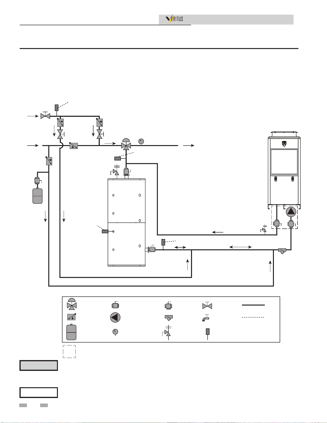
Installation & Operation Manual
4 System Piping
NOTICE
Please note that these illustrations are meant to show system piping concept only, the installer is responsible
for all equipment. The installer must follow all manufacturer’s instructions for each system component. The
installer is responsible for compliance with local codes.
The piping will not support the weight of the water heater circulator pump. Do not attempt to support the
weight of the water heater circulator pump with the piping or its accessories. Refer to the pump manufacturer’s
installation instructions. Failure to comply could result in severe personal injury, death, or substantial property
damage.
⚠ CAUTION
Figure 4-2 Single Pass - One Heater, One Tank
SINGLE PASS, RETURN TO PRIMARY:
ONE HEAT PUMP, ONE TANK
MIXED WATER SUPPLY
TO BUILDING
BUILDING
RECIRC
COLD WATER
SUPPLY
HP WATER HEATER
MIXING VALVE
CHECK VALVE
EXPANSION TANK
ISOLATION VALVE
CIRCULATING PUMP
TEMPERATURE GAUGE
WYE STRAINER
TEMP/PRESS RELIEF
VALVE
ISOLATING
FLUSH VALVE
PIPING
WIRING
TEMPERATURE
SENSOR
BALANCING
VALVE
FLUSH VALVE
RECIRC RETURN SENSOR (OPTIONAL)
SYSTEM SUPPLY SENSOR (OPTIONAL)
TANK SENSOR
SYSTEM RETURN SENSOR (OPTIONAL)
THERMAL STORAGE
Included with heat pump manifold
NOTES:
1. DRAWING ILLUSTRATES SUGGESTED PIPING CONFIGURATION
LOCAL CODES AND ORDINANCES MAY HAVE ADDITIONAL REQUIREMENTS
2. DO NOT INCLUDE CHECK VALVES BETWEEN HEAT PUMP OUTLET AND TANK UNLESS REQUIRED
BY CODE. INTERNAL HEAT PUMP VALVE PREVENTS BACKFLOW
3. CHECK VALVE REQUIRED TO PREVENT BACKFLOW TO COLD WATER SUPPLY
4. SYSTEM REQUIRES ONE TANK SENSOR BUT WILL SUPPORT UP TO SIX TANK SENSORS
SEE NOTE 3
Note: For suggested pipe size, see Table 4-2.
30
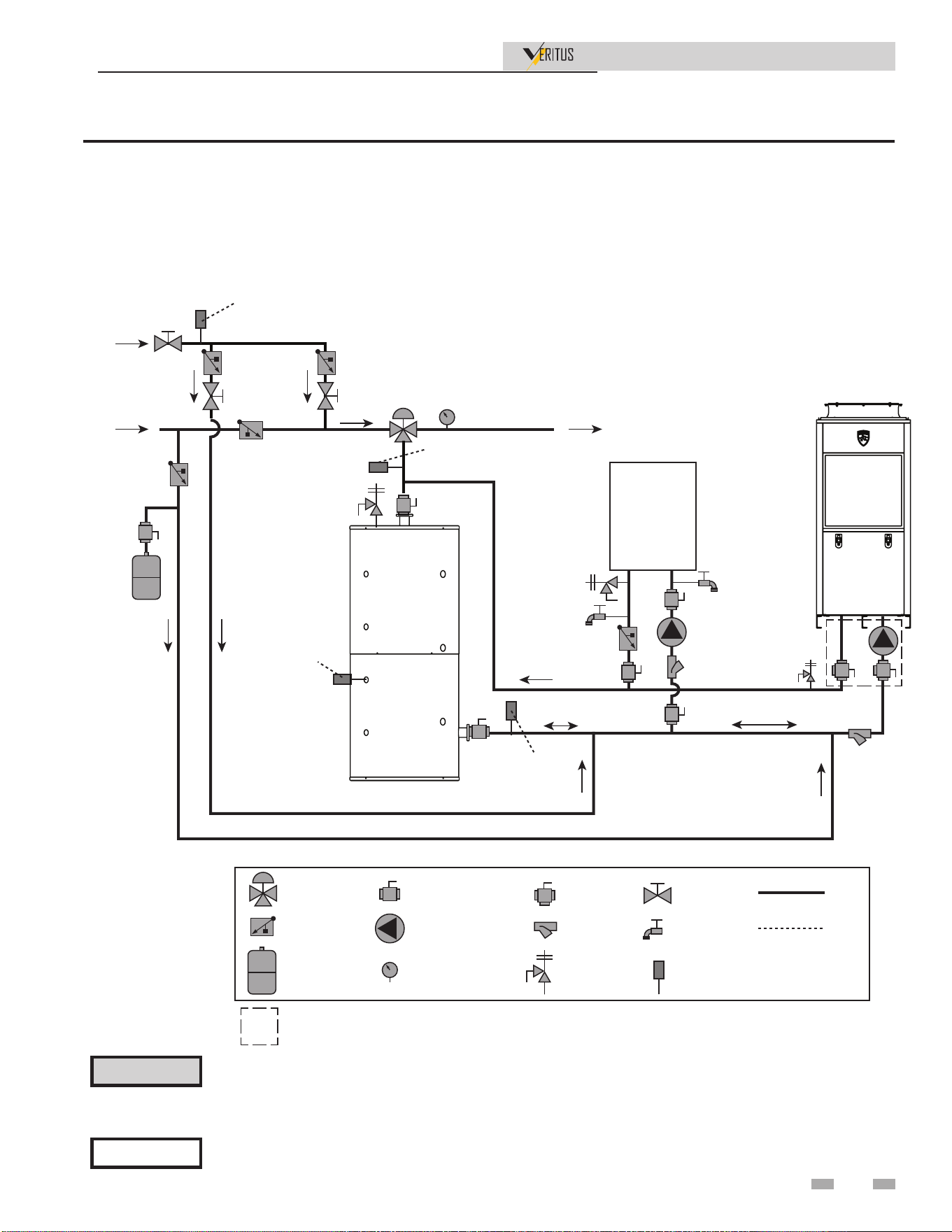
Installation & Operation Manual
4 System Piping (continued)
NOTICE
Please note that these illustrations are meant to show system piping concept only, the installer is responsible
for all equipment. The installer must follow all manufacturer’s instructions for each system component. The
installer is responsible for compliance with local codes.
The piping will not support the weight of the water heater circulator pump. Do not attempt to support
the weight of the water heater circulator pump with the piping or its accessories. Refer to the pump
manufacturer’s installation instructions. Failure to comply could result in severe personal injury, death, or
substantial property damage.
⚠ CAUTION
Figure 4-3 Single Pass - One Heater, One Tank with Parallel Backup
SINGLE PASS, RETURN TO PRIMARY:
ONE HEAT PUMP, ONE TANK, PARALLEL BACKUP
MIXED WATER SUPPLY
TO BUILDING
BUILDING
RECIRC
COLD WATER
SUPPLY
HP WATER HEATER
MIXING VALVE
CHECK VALVE
EXPANSION TANK
ISOLATION VALVE
CIRCULATING PUMP
TEMPERATURE GAUGE
WYE STRAINER
TEMP/PRESS RELIEF
VALVE
ISOLATING
FLUSH VALVE
PIPING
WIRING
TEMPERATURE
SENSOR
BALANCING
VALVE
FLUSH VALVE
RECIRC RETURN SENSOR (OPTIONAL)
SYSTEM SUPPLY
SENSOR (OPTIONAL)
TANK SENSOR
SYSTEM RETURN
SENSOR (OPTIONAL)
INSTANTANEOUS
OR
ELECTRIC TANK
THERMAL STORAGE
SEE NOTE 4
Included with heat pump manifold
NOTES:
1. DRAWING ILLUSTRATES SUGGESTED PIPING CONFIGURATION
LOCAL CODES AND ORDINANCES MAY HAVE ADDITIONAL REQUIREMENTS
2. DO NOT INCLUDE CHECK VALVES BETWEEN HEAT PUMP OUTLET AND TANK UNLESS REQUIRED
BY CODE. INTERNAL HEAT PUMP VALVE PREVENTS BACKFLOW
3. CHECK VALVE REQUIRED TO PREVENT BACKFLOW TO COLD WATER SUPPLY
4. SYSTEM REQUIRES ONE TANK SENSOR BUT WILL SUPPORT UP TO SIX TANK SENSORS
SEE NOTE 3
Note: For suggested pipe size, see Table 4-2.
31
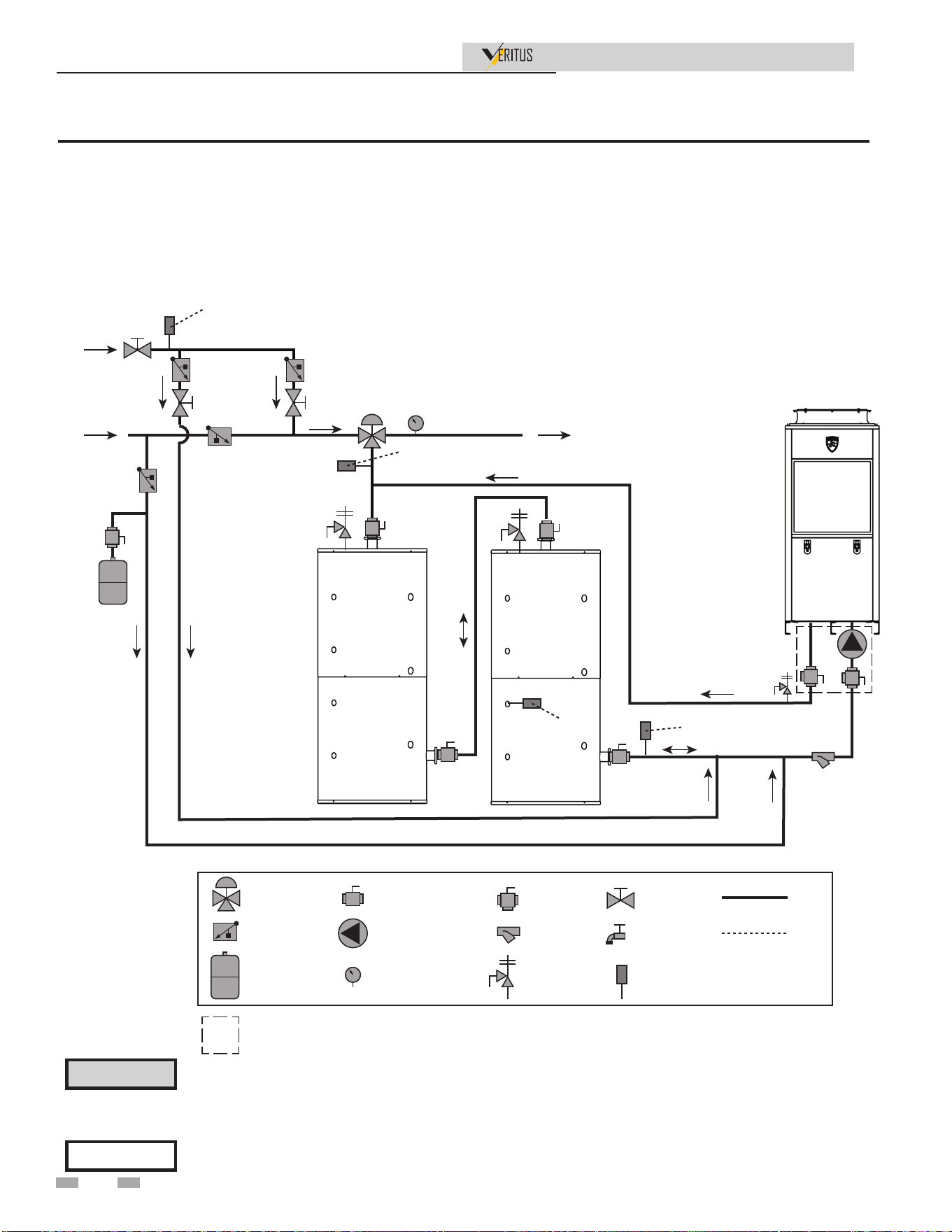
4 System Piping
Installation & Operation Manual
NOTICE
Please note that these illustrations are meant to show system piping concept only, the installer is responsible
for all equipment. The installer must follow all manufacturer’s instructions for each system component. The
installer is responsible for compliance with local codes.
The piping will not support the weight of the water heater circulator pump. Do not attempt to support
the weight of the water heater circulator pump with the piping or its accessories. Refer to the pump
manufacturer’s installation instructions. Failure to comply could result in severe personal injury, death, or
substantial property damage.
⚠ CAUTION
Figure 4-4 Single Pass - One Heater, Two Tanks
SINGLE PASS RETURN TO PRIMARY:
ONE HEAT PUMP, TWO TANKS
MIXED WATER SUPPLY
TO BUILDING
BUILDING
RECIRC
COLD WATER
SUPPLY
HP WATER HEATER
RECIRC RETURN SENSOR (OPTIONAL)
SYSTEM SUPPLY
SENSOR (OPTIONAL)
TANK
SENSOR
SYSTEM RETURN
SENSOR (OPTIONAL)
THERMAL STORAGE
THERMAL STORAGE
MIXING VALVE
CHECK VALVE
EXPANSION TANK
ISOLATION VALVE
CIRCULATING PUMP
TEMPERATURE GAUGE
WYE STRAINER
TEMP/PRESS RELIEF
VALVE
ISOLATING
FLUSH VALVE
PIPING
WIRING
TEMPERATURE
SENSOR
BALANCING
VALVE
FLUSH VALVE
Included with heat pump manifold
NOTES:
1. DRAWING ILLUSTRATES SUGGESTED PIPING CONFIGURATION
LOCAL CODES AND ORDINANCES MAY HAVE ADDITIONAL REQUIREMENTS
2. DO NOT INCLUDE CHECK VALVES BETWEEN HEAT PUMP OUTLET AND TANK UNLESS REQUIRED
BY CODE. INTERNAL HEAT PUMP VALVE PREVENTS BACKFLOW
3. CHECK VALVE REQUIRED TO PREVENT BACKFLOW TO COLD WATER SUPPLY
4. SYSTEM REQUIRES ONE TANK SENSOR BUT WILL SUPPORT UP TO SIX TANK SENSORS
SEE NOTE 3
Note: For suggested pipe size, see Table 4-2.
32
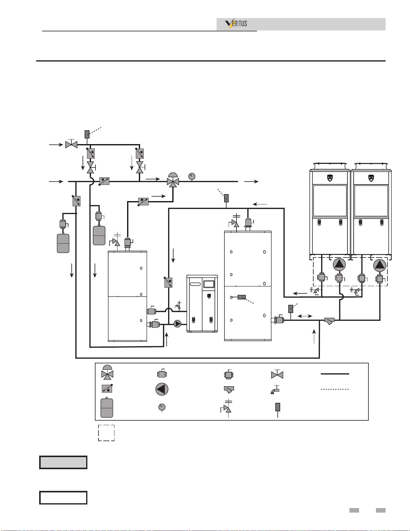
4 System Piping (continued)
Installation & Operation Manual
NOTICE
Please note that these illustrations are meant to show system piping concept only, the installer is responsible
for all equipment. The installer must follow all manufacturer’s instructions for each system component. The
installer is responsible for compliance with local codes.
The piping will not support the weight of the water heater circulator pump. Do not attempt to support
the weight of the water heater circulator pump with the piping or its accessories. Refer to the pump
manufacturer’s installation instructions. Failure to comply could result in severe personal injury, death, or
substantial property damage.
⚠ CAUTION
Figure 4-5 Single Pass - Two Heaters, One Tank with Swing Tank and Gas Backup Heat
MIXED WATER SUPPLY
TO BUILDING
BUILDING
RECIRC
COLD WATER
SUPPLY
HP WATER HEATER
RECIRC RETURN SENSOR (OPTIONAL)
SYSTEM SUPPLY
SENSOR (OPTIONAL)
TANK
SENSOR
SYSTEM RETURN
SENSOR (OPTIONAL)
HP WATER HEATER
SWING TANK
THERMAL STORAGE
MIXING VALVE
CHECK VALVE
EXPANSION TANK
ISOLATION VALVE
CIRCULATING PUMP
TEMPERATURE GAUGE
WYE STRAINER
TEMP/PRESS RELIEF
VALVE
ISOLATING
FLUSH VALVE
PIPING
WIRING
TEMPERATURE
SENSOR
BALANCING
VALVE
FLUSH VALVE
Included with heat pump manifold
NOTES:
1. DRAWING ILLUSTRATES SUGGESTED PIPING CONFIGURATION
LOCAL CODES AND ORDINANCES MAY HAVE ADDITIONAL REQUIREMENTS
2. DO NOT INCLUDE CHECK VALVES BETWEEN HEAT PUMP OUTLET AND TANK UNLESS REQUIRED
BY CODE. INTERNAL HEAT PUMP VALVE PREVENTS BACKFLOW
3. CHECK VALVE REQUIRED TO PREVENT BACKFLOW TO COLD WATER SUPPLY
4. SYSTEM REQUIRES ONE TANK SENSOR BUT WILL SUPPORT UP TO SIX TANK SENSORS
SEE NOTE 3
2000811709 REV A
Note: For suggested pipe size, see Table 4-2.
33
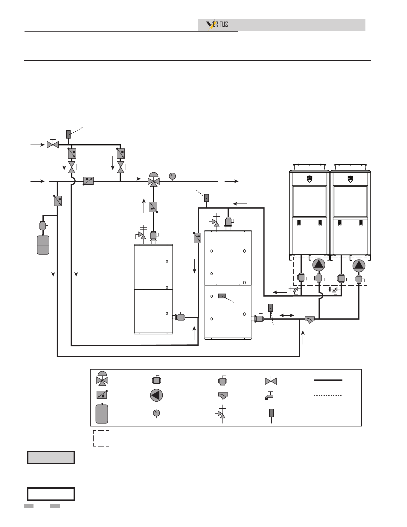
4 System Piping
Installation & Operation Manual
NOTICE
Please note that these illustrations are meant to show system piping concept only, the installer is responsible
for all equipment. The installer must follow all manufacturer’s instructions for each system component. The
installer is responsible for compliance with local codes.
The piping will not support the weight of the water heater circulator pump. Do not attempt to support
the weight of the water heater circulator pump with the piping or its accessories. Refer to the pump
manufacturer’s installation instructions. Failure to comply could result in severe personal injury, death, or
substantial property damage.
⚠ CAUTION
Figure 4-6 Single Pass - Two Heaters, One Tank with Swing Tank
SINGLE PASS RETURN TO SWING TANK:
TWO HEAT PUMPS, ONE TANK, SWING TANK
MIXED WATER SUPPLY
TO BUILDING
BUILDING
RECIRC
COLD WATER
SUPPLY
HP WATER HEATER
RECIRC RETURN SENSOR (OPTIONAL)
SYSTEM SUPPLY
SENSOR (OPTIONAL)
TANK
SENSOR
SYSTEM RETURN
SENSOR (OPTIONAL)
HP WATER HEATER
SWING TANK
THERMAL STORAGE
MIXING VALVE
CHECK VALVE
EXPANSION TANK
ISOLATION VALVE
CIRCULATING PUMP
TEMPERATURE GAUGE
WYE STRAINER
TEMP/PRESS RELIEF
VALVE
ISOLATING
FLUSH VALVE
PIPING
WIRING
TEMPERATURE
SENSOR
BALANCING
VALVE
FLUSH VALVE
Included with heat pump manifold
NOTES:
1. DRAWING ILLUSTRATES SUGGESTED PIPING CONFIGURATION
LOCAL CODES AND ORDINANCES MAY HAVE ADDITIONAL REQUIREMENTS
2. DO NOT INCLUDE CHECK VALVES BETWEEN HEAT PUMP OUTLET AND TANK UNLESS REQUIRED
BY CODE. INTERNAL HEAT PUMP VALVE PREVENTS BACKFLOW
3. CHECK VALVE REQUIRED TO PREVENT BACKFLOW TO COLD WATER SUPPLY
4. SYSTEM REQUIRES ONE TANK SENSOR BUT WILL SUPPORT UP TO SIX TANK SENSORS
SEE NOTE 3
Note: For suggested pipe size, see Table 4-2.
34
NOTICE
Please note that these illustrations are meant to show system piping concept only, the installer is responsible
for all equipment. The installer must follow all manufacturer’s instructions for each system component. The
installer is responsible for compliance with local codes.
The piping will not support the weight of the water heater circulator pump. Do not attempt to support
the weight of the water heater circulator pump with the piping or its accessories. Refer to the pump
manufacturer’s installation instructions. Failure to comply could result in severe personal injury, death, or
substantial property damage.
⚠ CAUTION
Figure 4-7 Single Pass - Two Heaters, Two Tanks
4 System Piping (continued)
Installation & Operation Manual
SINGLE PASS RETURN TO PRIMARY:
TWO HEAT PUMPS, TWO TANKS
MIXED WATER SUPPLY
TO BUILDING
BUILDING
RECIRC
COLD WATER
SUPPLY
HP WATER HEATER
RECIRC RETURN SENSOR (OPTIONAL)
SYSTEM SUPPLY
SENSOR (OPTIONAL)
TANK
SENSOR
SYSTEM RETURN
SENSOR (OPTIONAL)
HP WATER HEATER
THERMAL STORAGE
THERMAL STORAGE
MIXING VALVE
CHECK VALVE
EXPANSION TANK
ISOLATION VALVE
CIRCULATING PUMP
TEMPERATURE GAUGE
WYE STRAINER
TEMP/PRESS RELIEF
VALVE
ISOLATING
FLUSH VALVE
PIPING
WIRING
TEMPERATURE
SENSOR
BALANCING
VALVE
FLUSH VALVE
Included with heat pump manifold
NOTES:
1. DRAWING ILLUSTRATES SUGGESTED PIPING CONFIGURATION
LOCAL CODES AND ORDINANCES MAY HAVE ADDITIONAL REQUIREMENTS
2. DO NOT INCLUDE CHECK VALVES BETWEEN HEAT PUMP OUTLET AND TANK UNLESS REQUIRED
BY CODE. INTERNAL HEAT PUMP VALVE PREVENTS BACKFLOW
3. CHECK VALVE REQUIRED TO PREVENT BACKFLOW TO COLD WATER SUPPLY
4. SYSTEM REQUIRES ONE TANK SENSOR BUT WILL SUPPORT UP TO SIX TANK SENSORS
SEE NOTE 3
Note: For suggested pipe size, see Table 4-2.
35
4 System Piping
Installation & Operation Manual
NOTICE
Please note that these illustrations are meant to show system piping concept only, the installer is responsible
for all equipment. The installer must follow all manufacturer’s instructions for each system component. The
installer is responsible for compliance with local codes.
The piping will not support the weight of the water heater circulator pump. Do not attempt to support
the weight of the water heater circulator pump with the piping or its accessories. Refer to the pump
manufacturer’s installation instructions. Failure to comply could result in severe personal injury, death, or
substantial property damage.
⚠ CAUTION
Figure 4-8 Single Pass - Two Heaters, Two Tanks with Electric Backup
SINGLE PASS RETURN TO PRIMARY:
TWO HEAT PUMPS, TWO TANKS, ELECTRIC BACKUP
MIXING VALVE
CHECK VALVE
EXPANSION TANK
ISOLATION VALVE
CIRCULATING PUMP
TEMPERATURE GAUGE
WYE STRAINER
TEMP/PRESS RELIEF
VALVE
ISOLATING
FLUSH VALVE
PIPING
WIRING
TEMPERATURE
SENSOR
BALANCING
VALVE
FLUSH VALVE
ELECTRIC BACKUP TANK
MIXED WATER SUPPLY
TO BUILDING
BUILDING
RECIRC
COLD WATER
SUPPLY
HP WATER HEATER
RECIRC RETURN SENSOR (OPTIONAL)
SYSTEM SUPPLY
SENSOR (OPTIONAL)
TANK
SENSOR
SYSTEM RETURN
SENSOR (OPTIONAL)
HP WATER HEATER
THERMAL STORAGE
THERMAL STORAGE
BACKUP PUMP
Included with heat pump manifold
NOTES:
1. DRAWING ILLUSTRATES SUGGESTED PIPING CONFIGURATION
LOCAL CODES AND ORDINANCES MAY HAVE ADDITIONAL REQUIREMENTS
2. DO NOT INCLUDE CHECK VALVES BETWEEN HEAT PUMP OUTLET AND TANK UNLESS REQUIRED
BY CODE. INTERNAL HEAT PUMP VALVE PREVENTS BACKFLOW
3. CHECK VALVE REQUIRED TO PREVENT BACKFLOW TO COLD WATER SUPPLY
4. SYSTEM REQUIRES ONE TANK SENSOR BUT WILL SUPPORT UP TO SIX TANK SENSORS
SEE NOTE 3
Note: For suggested pipe size, see Table 4-2.
36
4 System Piping (continued)
Installation & Operation Manual
NOTICE
Please note that these illustrations are meant to show system piping concept only, the installer is responsible
for all equipment. The installer must follow all manufacturer’s instructions for each system component. The
installer is responsible for compliance with local codes.
The piping will not support the weight of the water heater circulator pump. Do not attempt to support
the weight of the water heater circulator pump with the piping or its accessories. Refer to the pump
manufacturer’s installation instructions. Failure to comply could result in severe personal injury, death, or
substantial property damage.
⚠ CAUTION
Figure 4-9 Multi Pass - One Heater, One Tank
MULTI PASS, RETURN TO PRIMARY:
ONE HEAT PUMP, ONE TANK
MIXED WATER SUPPLY
TO BUILDING
BUILDING
RECIRC
COLD WATER
SUPPLY
HP WATER HEATER
RECIRC RETURN SENSOR (OPTIONAL)
SYSTEM SUPPLY
SENSOR (OPTIONAL)
TANK SENSOR
SEE NOTE 4
SYSTEM RETURN
SENSOR (OPTIONAL)
THERMAL STORAGE
MIXING VALVE
CHECK VALVE
EXPANSION TANK
ISOLATION VALVE
CIRCULATING PUMP
TEMPERATURE GAUGE
WYE STRAINER
TEMP/PRESS RELIEF
VALVE
ISOLATING
FLUSH VALVE
PIPING
WIRING
TEMPERATURE
SENSOR
BALANCING
VALVE
FLUSH VALVE
Included with heat pump manifold
NOTES:
1. DRAWING ILLUSTRATES SUGGESTED PIPING CONFIGURATION
LOCAL CODES AND ORDINANCES MAY HAVE ADDITIONAL REQUIREMENTS
2. DO NOT INCLUDE CHECK VALVES BETWEEN HEAT PUMP OUTLET AND TANK UNLESS REQUIRED
BY CODE. INTERNAL HEAT PUMP VALVE PREVENTS BACKFLOW
3. CHECK VALVE REQUIRED TO PREVENT BACKFLOW TO COLD WATER SUPPLY
4. SYSTEM REQUIRES ONE TANK SENSOR BUT WILL SUPPORT UP TO SIX TANK SENSORS
SEE NOTE 3
Note: For suggested pipe size, see Table 4-2.
37
4 System Piping
Installation & Operation Manual
Figure 4-10 Single Pass - One Heater, One Tank - Long Pipe Runs
NOTICE
Please note that these illustrations are meant to show system piping concept only, the installer is responsible
for all equipment. The installer must follow all manufacturer’s instructions for each system component. The
installer is responsible for compliance with local codes.
The piping will not support the weight of the water heater circulator pump. Do not attempt to support the
weight of the water heater circulator pump with the piping or its accessories. Refer to the pump manufacturer’s
installation instructions. Failure to comply could result in severe personal injury, death, or substantial property
damage.
⚠ CAUTION
MIXED WATER SUPPLY
TO BUILDING
BUILDING
RECIRC
COLD WATER
SUPPLY
HP WATER HEATER
RECIRC RETURN SENSOR (OPTIONAL)
SYSTEM SUPPLY
SENSOR (OPTIONAL)
TANK
SENSOR
SYSTEM RETURN
SENSOR (OPTIONAL)
THERMAL STORAGE
THERMAL STORAGE
MIXING VALVE
CHECK VALVE
EXPANSION TANK
ISOLATION VALVE
CIRCULATING PUMP
TEMPERATURE GAUGE
WYE STRAINER
TEMP/PRESS RELIEF
VALVE
ISOLATING
FLUSH VALVE
PIPING
WIRING
TEMPERATURE
SENSOR
BALANCING
VALVE
FLUSH VALVE
Included with heat pump manifold
NOTES:
1. DRAWING ILLUSTRATES SUGGESTED PIPING CONFIGURATION
LOCAL CODES AND ORDINANCES MAY HAVE ADDITIONAL REQUIREMENTS
2. DO NOT INCLUDE CHECK VALVES BETWEEN HEAT PUMP OUTLET AND T
ANK UNLESS REQUIRED
BY CODE. INTERNAL HEAT PUMP VALVE PREVENTS BACKFLOW
3. CHECK VALVE REQUIRED TO PREVENT BACKFLOW TO COLD WATER SUPPLY
4. SYSTEM REQUIRES ONE TANK SENSOR BUT WILL SUPPORT UP TO SIX TANK SENSORS
SEE NOTE 3
2000811714 REV A
MIXED WATER SUPPLY
TO BUILDING
BUILDING
RECIRC
COLD WATER
SUPPLY
HP WATER HEATER
RECIRC RETURN SENSOR (OPTIONAL)
SYSTEM SUPPLY
SENSOR (OPTIONAL)
TANK
SENSOR
SYSTEM RETURN
SENSOR (OPTIONAL)
THERMAL STORAGE
THERMAL STORAGE
MIXING VALVE
CHECK VALVE
EXPANSION TANK
ISOLATION VALVE
CIRCULATING PUMP
TEMPERATURE GAUGE
WYE STRAINER
TEMP/PRESS RELIEF
VALVE
ISOLATING
FLUSH VALVE
PIPING
WIRING
TEMPERATURE
SENSOR
BALANCING
VALVE
FLUSH VALVE
Included with heat pump manifold
NOTES:
1. DRAWING ILLUSTRATES SUGGESTED PIPING CONFIGURATION
LOCAL CODES AND ORDINANCES MAY HAVE ADDITIONAL REQUIREMENTS
2. DO NOT INCLUDE CHECK VALVES BETWEEN HEAT PUMP OUTLET AND TANK UNLESS REQUIRED
BY CODE. INTERNAL HEAT PUMP VALVE PREVENTS BACKFLOW
3. CHECK VALVE REQUIRED TO PREVENT BACKFLOW TO COLD WATER SUPPLY
4. SYSTEM REQUIRES ONE TANK SENSOR BUT WILL SUPPORT UP TO SIX TANK SENSORS
SEE NOTE 3
2000811714 REV A
Note: For suggested pipe size, see Table 4-2.
38
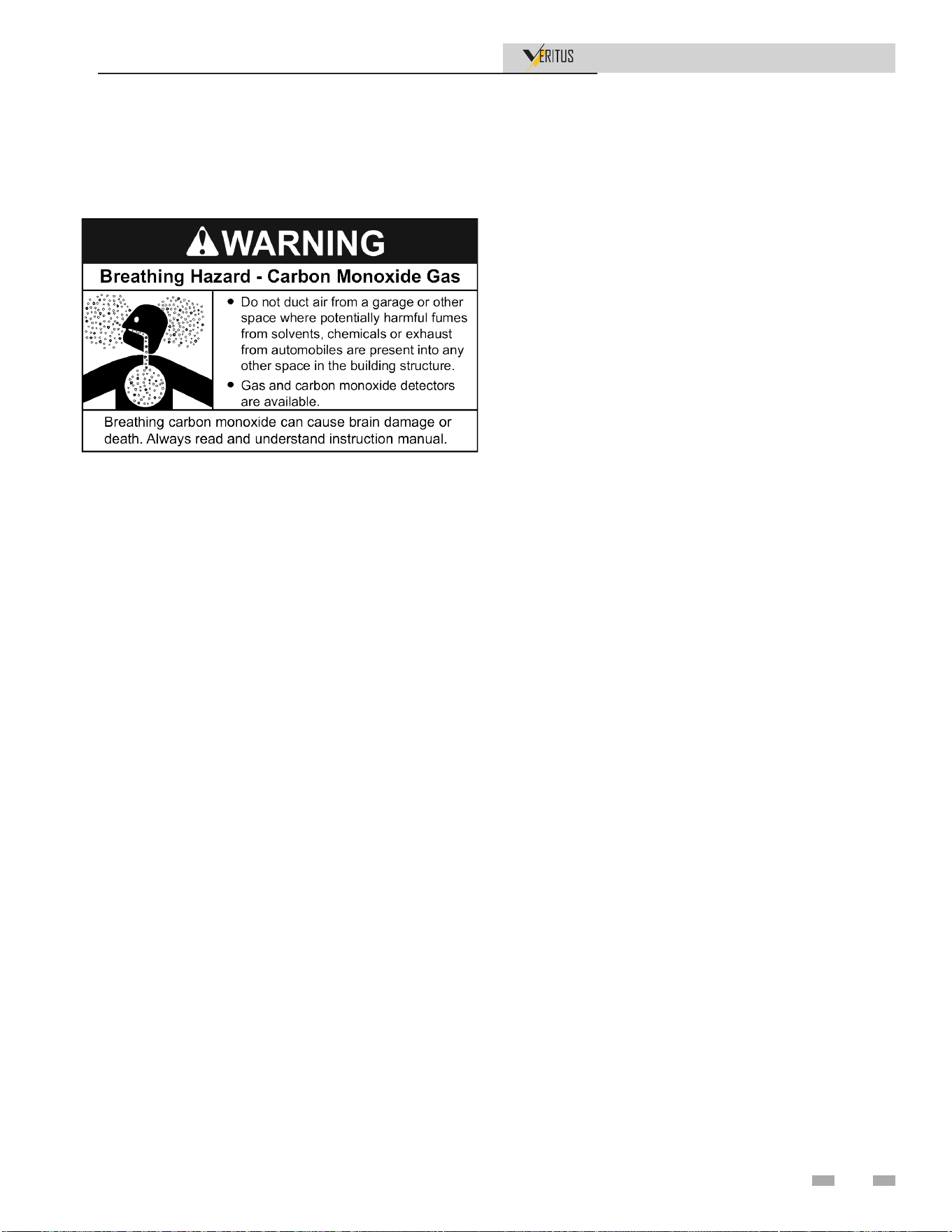
5 Air Flow and Ducting
Installation & Operation Manual
General Guidelines
Review Locating The Water Heater on page 17, and this section
prior to connecting ductwork to the HPWH.
The supply (outlet) air from a HPWH installed in a garage or a
unit drawing return (inlet) air from a garage or any area where
solvents or other chemicals that emit potentially harmful fumes
are stored or automobiles are located must never be ducted
to any other space inside the building structure. This would
include all occupied and unoccupied spaces such as attics or
basements. Potentially harmful fumes and vapors could be
introduced into occupied spaces. See Unit Placement on page
23.
Duct Sizing
Supply and return air ducting must be sized properly to
ensure requirements for the total equivalent supply and return
duct lengths allowed. Exceeding those maximum lengths will
adversely affect the operation of the heat pump. Consult the
factory for sizing.
Duct Insulation
The cooled air from the HPWH may be below room dew point.
Insulate the supply duct to prevent dripping from moisture
condensing on the duct. It is not necessary to insulate return
ducts unless the air in the return duct is colder than the room
air. Also consider insulating all ductwork to reduce blower
noise from the unit.
Make Duct Connections
Install all ductwork to and from unit in accordance with all
applicable codes. Duct construction must allow unit to operate
within the limits of the unit external static pressure as in the
HPWH unit’s performance and specification sheets. See Table
1-1 on page 19 also. Use flexible connections to minimize duct-
to-duct alignment problems and noise transmission. Install
ductwork, accessory grilles, and plenums so that they do not
restrict access to the optional filter (consult factory for merv
rating), and so they prevent dirt, dust, and debris from settling
in the unit.
Ducting Multiple Units
The HPWHs can be ducted together into a common header,
but only if the static pressure can be maintained with the other
pieces of equipment. If this is done, the Engineer of Record
needs to take extra precautions around this design and assumes
responsibility for overdrawing amperage on the motors, blown
fuses, and all other air side issues that may arise.
Building Air Pressure
When installing ducting to or from an alternate location (other
than the installed space) both the supply (outlet) and return
(inlet) air may need to be ducted to prevent positive or negative
building air pressure conditions within the installed space.
Negative Pressure
Ducting supply air only to an alternate location, such as the
outdoors, may cause excessive negative air pressure inside
the building envelope. Excessive negative pressure inside the
building structure may result in cold or hot air from outdoors
being drawn inside the building and place additional load on
space heating and cooling equipment. Negative air pressure
in buildings can also cause reverse flow in chimneys and gas
vents.
Positive Pressure
Ducting return air only from an alternate location, such as the
outdoors, may cause excessive positive air pressure inside the
building envelope.
Excessive positive pressure inside the building structure may
place additional load on space heating and cooling equipment
by interfering with the delivery of conditioned air.
When to Install Ducting
HPWH units are often installed in unoccupied spaces or
equipment rooms where there is an ample source of ambient
heat and no need to redirect the supply air to another location.
Ductwork is not necessary in these circumstances. See Heat
Source on page 17.
Typical applications when ducting is installed.
• Duct supply (outlet) air to alternate location for spot
cooling or discard supply air not wanted in the installed
space.
• Duct return (inlet) air from an alternate location (outdoors,
warm equipment room) to optimize efficiency.
39
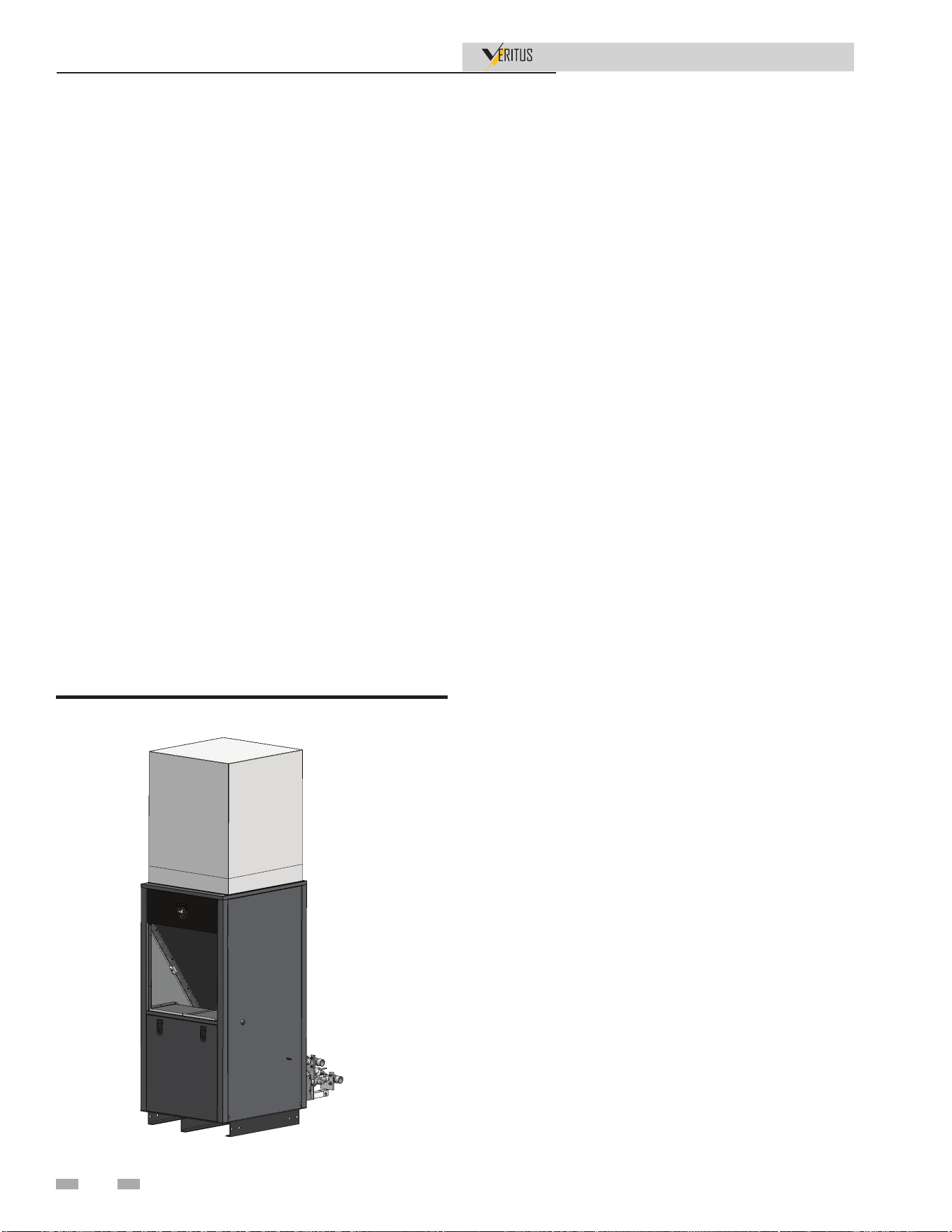
5 Air Flow and Ducting (continued)
Installation & Operation Manual
Supply Air Ducting
Observe and follow these guidelines and instructions when
installing supply (outlet) air duct:
• When duct work is not field connected to the supply air
outlet on the HPWH unit a field supplied safety guard
must be installed over the supply air connection. Failure
to comply could result in severe injury.
• All duct work and plenums shall be field supplied or
fabricated.
• The maximum supply air duct length shall not exceed 6FT.
If a 2 FT riser is attached to the unit, the maximum air
duct length can be increased up to 9 FT. Exceeding these
maximum lengths will adversely affect the operation of the
heat pump. Consult the factory for sizing.
• The maximum supply air duct length shall not exceed
6 ft. If a 2 ft riser is attached to the unit, the maximum air
duct length can be increased up to 9 ft. Exceeding these
maximum lengths will adversely affect the operation of the
heat pump. Consult the factory for sizing.
• Cooling output (supply air) from the HPWH is
supplemental only and must not be factored into sizing
calculations for space cooling equipment. Cooling output
is only produced when the HPWH is operating to satisfy a
water heating demand. Once the storage tank temperature
is satisfied, the HPWH will stop until the next water
heating demand is initiated regardless of space cooling
needs.
• All duct work and plenums shall be field supplied or
depending on the temperature of the air entering the HPWH
unit the supply air may not be suitable for supplemental
space cooling purposes. A field supplied/fabricated flex
connector should be added between the unit and duct for
service work when required.
• The air temperature drops approximately 12°F to 20°F (7°C
to 11°C) as it flows through the HPWH unit. If the return air
to the HPWH unit is derived from a location that is above
80°F (27°C) the supply air from the HPWH unit will not be
suitable for offsetting the building cooling load. This will
often be the case when the return air is ducted from a warm
equipment room or from the outdoor atmosphere. In these
circumstances do not duct supply air to another location for
spot cooling.
• Ducting supply air only to an alternate location, such as the
outdoors, may cause excessive negative air pressure inside
the building envelope.
• Provision must be made to prevent a negative pressure in
the installed space or building envelope. Return air must be
supplied to the HPWH from the alternate location through
ducting or louvers that communicate with the alternate
location where the supply ducting terminates. See the Return
Air Ducting section that follows.
• When installing the duct, install a flex connector between
the duct and unit for serviceability.
Figure 5-1 Supply air ducting
40
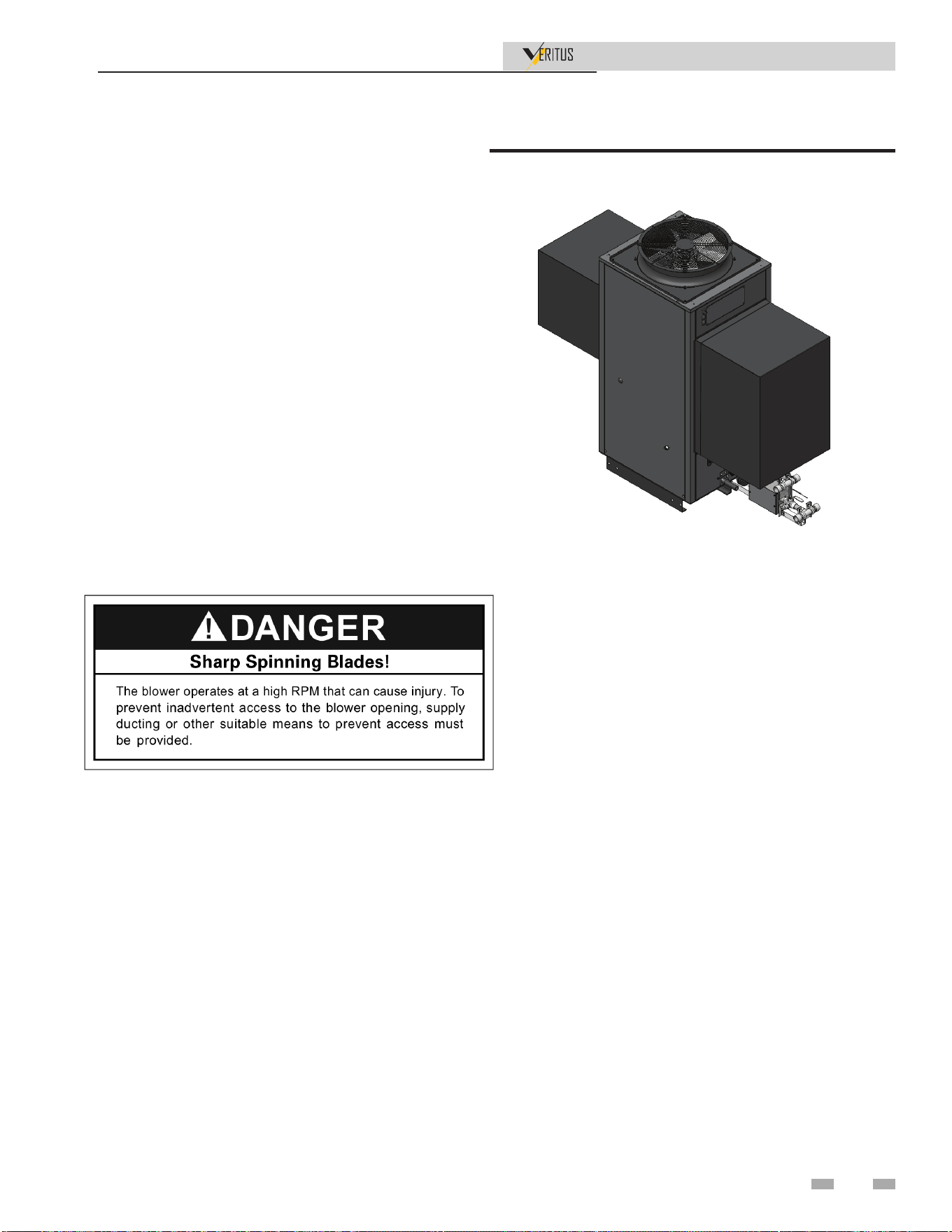
5 Air Flow and Ducting
Installation & Operation Manual
Return Air Ducting
Observe and follow these guidelines and instructions when
installing return (inlet) air duct:
• All ductwork and plenums shall be field supplied or
fabricated.
• When installing return air duct to the HPWH unit a
field supplied/fabricated flex connector should be added
between the unit and duct for service work when required.
• If a field supplied filter is required choose a location that
has easy access for servicing the filter as needed.
• Ducting return air only from an alternate location, such
as the outdoors, may cause excessive positive air pressure
inside the building envelope.
• Provision must be made to prevent a positive pressure in
the installed space or building envelope. Supply air must
be supplied to the HPWH from the alternate location
through ducting that communicates with the alternate
location from where the return air is derived. See the
preceding Supply Air Ducting section.
• When installing the duct, install a flex connector between
the duct and unit for serviceability.
Figure 5-2 Return air ducting
41
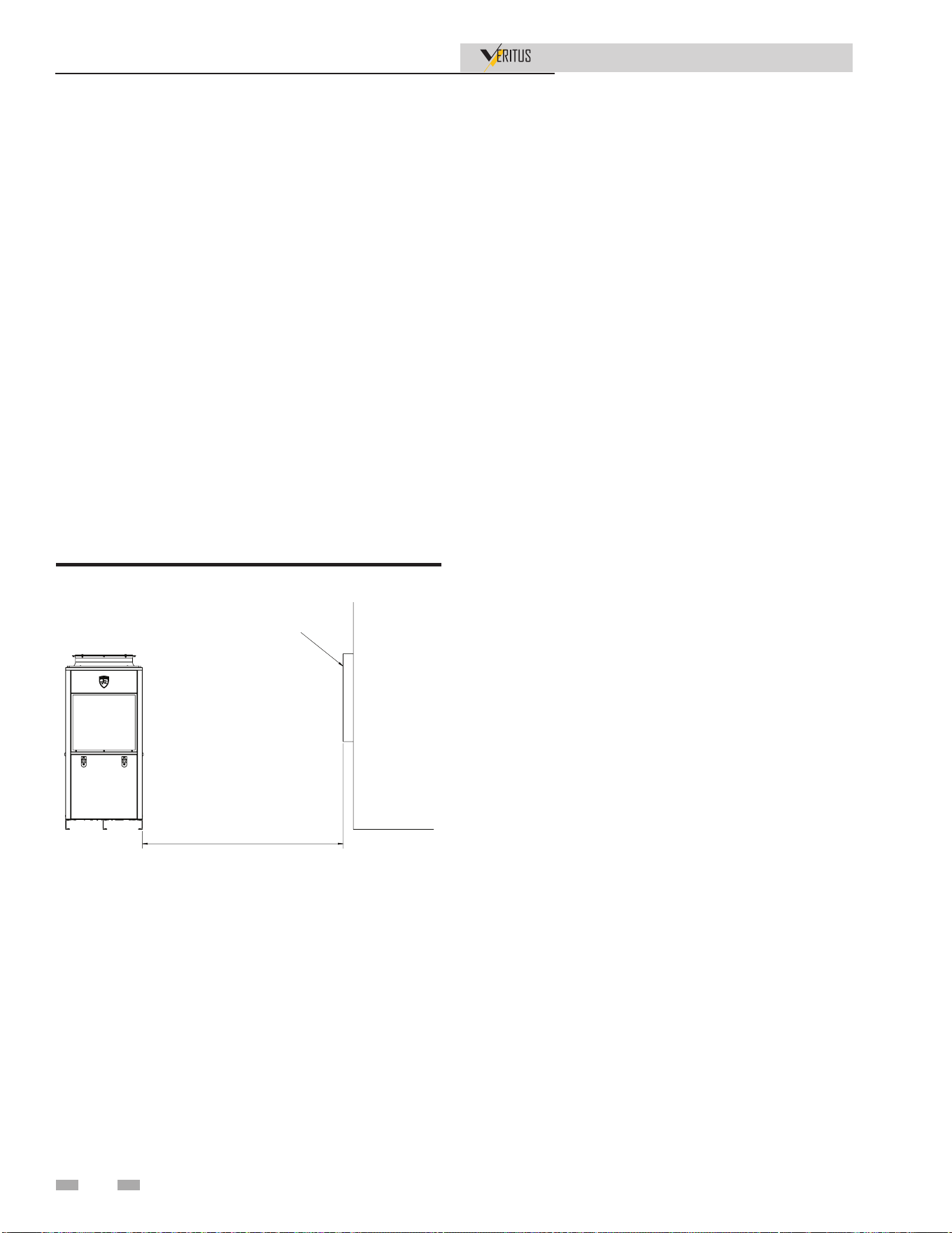
Figure 6-1 Unit distance from forced air inlet
6 Outdoor Installations
Installation & Operation Manual
Outdoor Air Inlet and Outlet
Keep HPWH air intake areas free of obstructions. Keep area
clean and free of corrosive materials. Maintain a minimum
of 36 inches (915 mm) clearance to the air inlet. To avoid a
blocked air inlet or outlet condition, keep the air inlet, air
outlet, and drain clear of leaves, debris, etc.
Do not install outdoor models directly on the ground. You
must install the outdoor unit on a concrete, brick, block, or
other noncombustible pad.
Do not locate unit so that high winds can deflect off of adjacent
walls, buildings, or shrubbery causing recirculation.
Locate unit at least 10 feet (3.05 m) away from any forced air
inlet. See Figure 6-1.
Locate unit at least 3 feet (0.91 m) outside any overhang.
Clearances around outdoor installations can change with time.
Do not allow the growth of trees, shrubs, or other plants to
obstruct the proper operation of the outdoor vent system.
Do not install in locations where rain from building runoff
drains will spill onto the unit.
)((7
)25&('$,5,1/(7
42
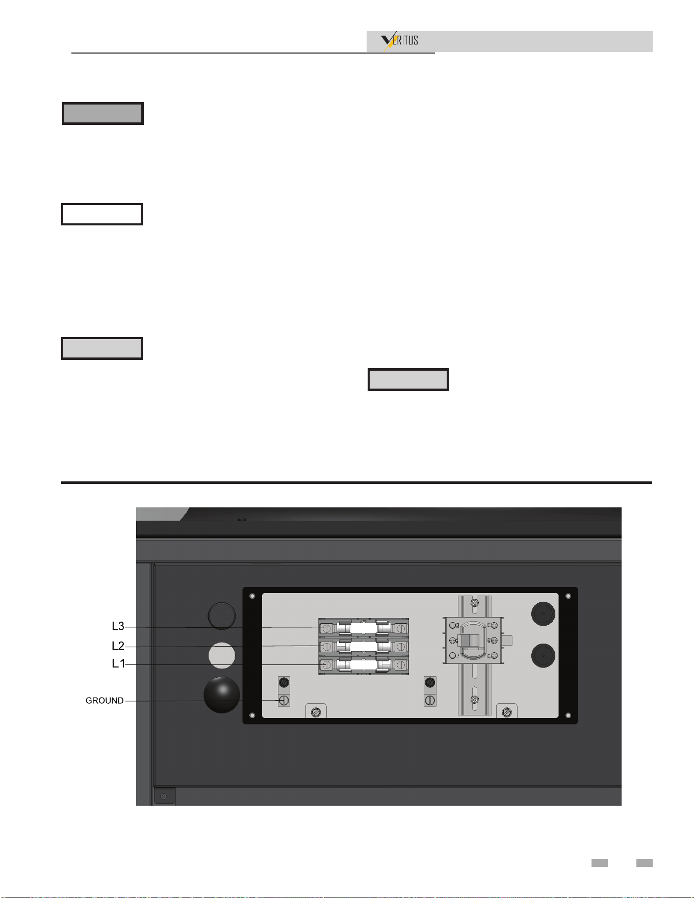
7 Field Wiring
Installation & Operation Manual
NOTICE
⚠ CAUTION
⚠ CAUTION
⚠ WARNING
ELECTRICAL SHOCK HAZARD – For
your safety, turn off electrical power supply
before making any electrical connections
to avoid possible electric shock hazard.
Failure to do so can cause severe personal
injury or death.
Wiring must be N.E.C. Class 1.
If original wiring as supplied with the
water heater must be replaced, use only
type 105°C wire or equivalent.
The water heater must be electrically
grounded as required by National
Electrical Code ANSI/NFPA 70 – latest
edition.
Label all wires prior to disconnection
when servicing controls. Wiring errors can
cause improper and dangerous operation.
If an optional field-installed E-Stop
is required, it MUST BE wired in series
with all nongrounded current-carrying
conductors per local and national codes to
ensure proper power disconnect per each
water heater. There is no other electrical
connection to the water heater that serves
as an emergency disconnect.
Figure 7-1A Line Voltage Field Wiring Main Power Connections - 10kA SCCR rating
Line voltage connections
1. Connect supply power wiring to the line voltage fuse block
in the junction box, as shown in Figure 7-1. Modular
Units (AHP200, AHP280, and AHP350) have line voltage
connections for each base model (AHP060 and AHP140).
AHP200 and AHP280 have 2-line connections, and the
AHP350 has 3-line connections.
2. Provide and install a fused disconnect (or service switch
sized per the HPWH amp draw (shown on the HPWH
rating plate) as required by the code.
3. For alternate voltages, consult factory.
4. Route pump wires through the knockouts in the lower
back panel of the unit, as shown in Figure 7-2.
5. The display panel with require 120 VAC to power the
system board. Route all wires through the conduit using
knockouts in the bottom side of the display panel, as
shown in Figure 7-3.
Installation must comply with:
1. National Electrical Code and any other national, state,
provincial, or local codes, or regulations.
2. In Canada, CSA C22.1 Canadian Electrical Code Part 1,
and any local codes.
43
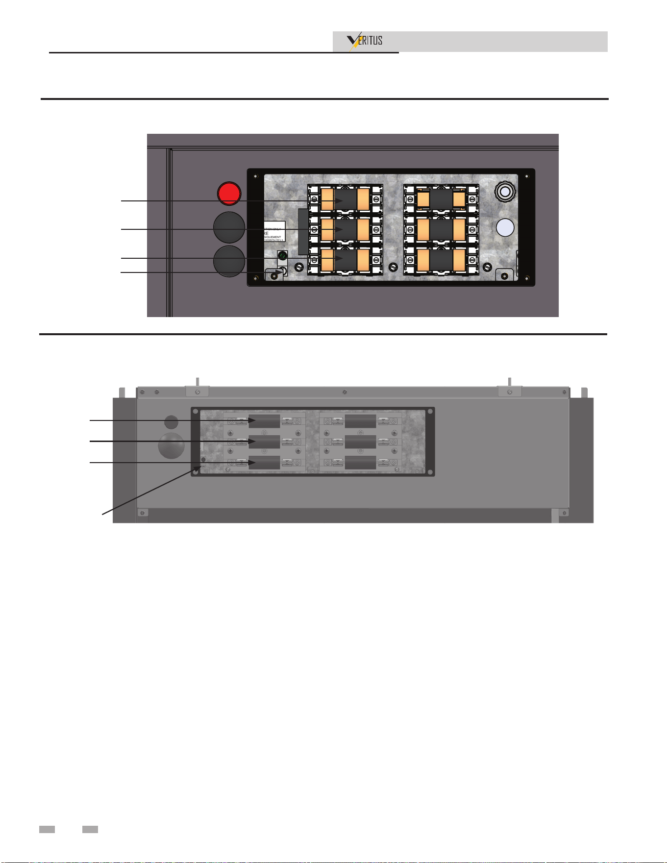
7 Field Wiring
Installation & Operation Manual
Figure 7-1B Line Voltage Field Wiring Main Power Connections - 100kA SCCR rating (AHP060-208, AHP060-480,
AHP140-480)
Figure 7-1C Line Voltage Field Wiring Main Power Connections - 100kA SCCR rating (AHP140-208)
GROUND
L1
L2
L3
2000845862 00
GROUND
L1
L2
L3
44
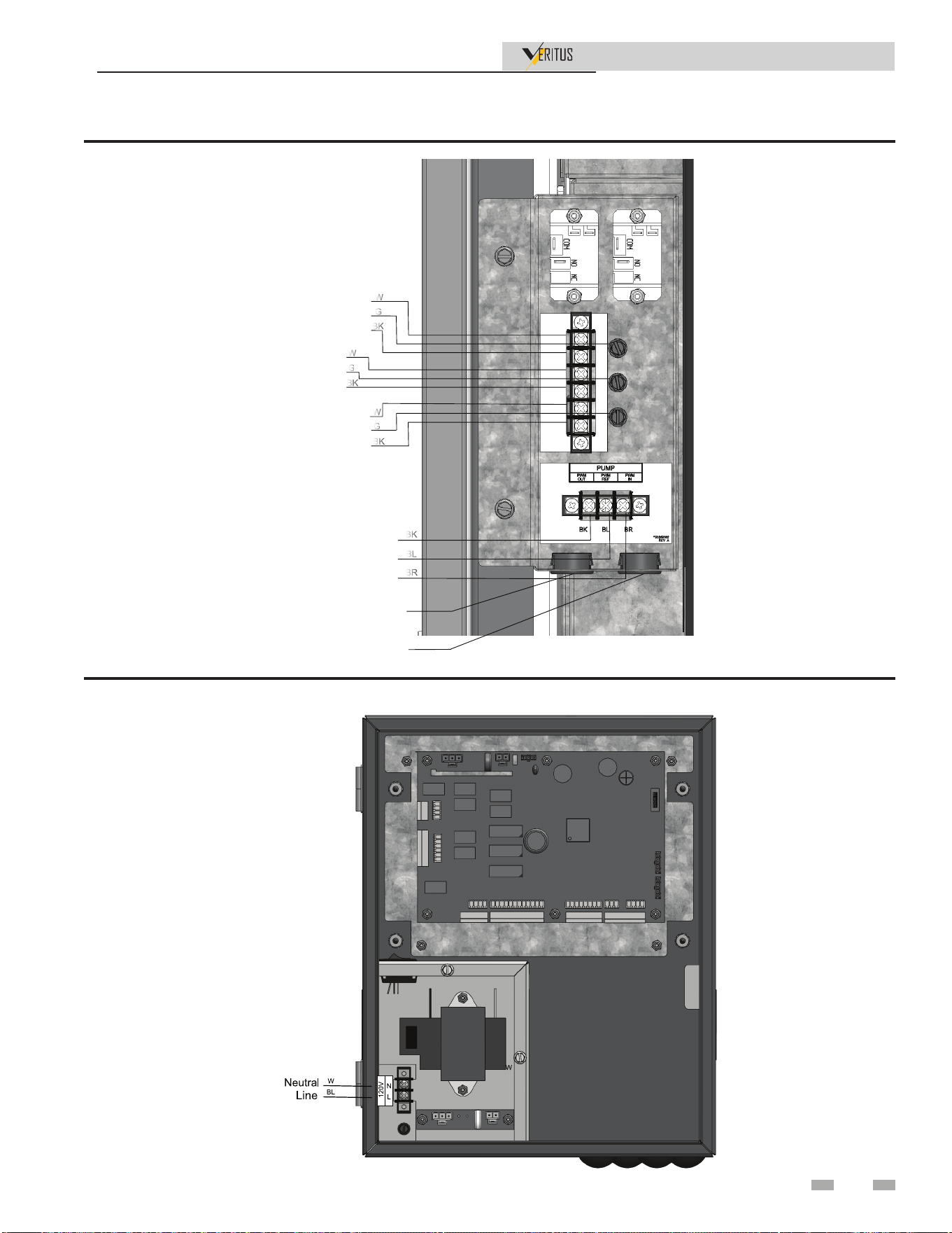
7 Field Wiring (continued)
Installation & Operation Manual
Figure 7-3 Wiring Display Box Power
Figure 7-2 Pump Wiring
1(875$/
/,1(
*5281'
1(875$/
/,1(
*5281'
1(875$/
/,1(
*5281'
:
*
%.
+($7&$%/(
:
*
%.
%2267(5
)$1
:
*
%.
':+3803
%.
%/
%5
3:06,*1$/287
3:05()(5(1&(
3:06,*1$/,1
3803
&20081,&$7,21
3:03:03:0
/,1(92/7$*(
:,5,1*.12&.2876
&20081,&$7,21
:,5,1*.12&.2876
45

7 Field Wiring
Installation & Operation Manual
Low Voltage Connections
1. Route all low voltage wires through the knockouts in the
bottom of the display panel, and reference connections in
Figure 7-5.
2. Connect low voltage wiring to the system control board as
shown in Figure 7-1 of this manual and the HPWH wiring
diagram.
High Voltage Connections
Booster Blower
Connect an external 120VAC relay to power a booster blower at
the connections shown in Figure 7-2 if desired. The maximum
allowed amp draw is 0.50A. These terminals will be powered
with 120VAC whenever the heat pump fan is operating.
Heat Cable
Connect an external 120VAC auxiliary heat cable at the
connections shown in Figure 7-2 if desired. The maximum
power available at this connection is 50VA which will, for
example, accommodate about 8 feet of field supplied heat
cable with a 6W/foot rating. For anything greater, a field
supplied relay is needed.
Tank Thermostat
1. A tank sensor is required for use. Additionally, a thermostat
or another type of switch may be used in conjunction with
a sensor to enable or disable the water heater. Remove
the jumper and connect the thermostat at the J2 Enable
contacts, as shown in Figure 7-5.
Tank Sensor
1. There are board connections for one to six sensors, but
only one is required. By installing the tank sensor, the
SMART TOUCH control can perform the tank thermostat
function. The SMART TOUCH control automatically
detects the presence of this sensor and generates a DHW
call for heat when the tank temperature drops below the
programmed differential and finishes the call for heat
when the tank temperature reaches above the programmed
offset.
2. The tank sensor 100208545 is the only sensor suitable for
use with the SMART TOUCH control. Connect the sensor
leads to the tank sensor terminals on the system control
board (Figure 7-5).
Louver Proving Switch
When the operation of the louvers needs to be verified before
the water heater starts, remove the jumper wire from these
terminals and connect them to the normally open contacts on
its proving switch (Figure 7-5).
ModBus / BACnet
When the optional ModBus / BACnet interface module is
installed, the RS-485 ModBus / BACnet cable is connected
to these terminals. Use shielded, 2-wire twisted pair cable. If
desired, the shield can be connected to ground by installing a
jumper wire between terminals 1 and 3 on connector X5 on the
optional ModBus / BACnet interface module.
Water Heater Building Management
System (BMS)
1. An external control may be connected to control the
set point of the water heater. Always jumper or switch
the BMS enable contacts J2-5 and J2-6 when using BMS
control. If the external control uses a set of contacts to
enable the water heater, connect the contacts to the Tank
Thermostat terminals. Otherwise, the SMART TOUCH
control will be enabled by the 0-10V signal.
2. Make sure the (-) terminal is connected to the (-) or
common output terminal of the external control, and
the (+) terminal is connected to the (+) or 0 - 10 VDC
terminal of the external control. Make sure the (-) voltage
is not below ground.
Runtime contacts
The SMART TOUCH control closes a set of dry contacts
whenever the heat pump is running. This is typically used by
Building Management Systems to verify that the water heater
is responding to a call for heat.
Alarm contacts
The SMART TOUCH control closes another set of contacts
whenever the water heater is locked out or the power is turned
off. This can be used to turn on an alarm, or signal a Building
Management System that the water heater is down.
Wiring of the Cascade
Connect the tank sensor to the system control board. For
the Cascade system to work properly, the tank sensor must
be installed. The tank sensor should be wired to the system
control board at the terminals marked for the tank sensor. The
control will use the water temperature at the tank sensor to
control the operation of the Cascade.
Replaceable Fuses
• Time Delay SC Class G, 600VAC, 40 Amp (Only on units
with 10kA SCCR rating)
• Class J, 600VAC, 40 Amp (Only on 480V units with SCCR
100kA Rating)
• Time Delay SC Class G, 600VAC, 1 Amp
• Inline Fuse: Eaton AHC-2-R, 2A 600VAC, 10KA (480V
units only)
• Class J, 600VAC, 50 Amp (AHP060-208 model only)
• Class J, 600VAC, 80 Amp (AHP140-208 model only)
• Inline Fuse: Eaton AHC-4-R, 4A 600VAC, 10kA (208V
units only)
46
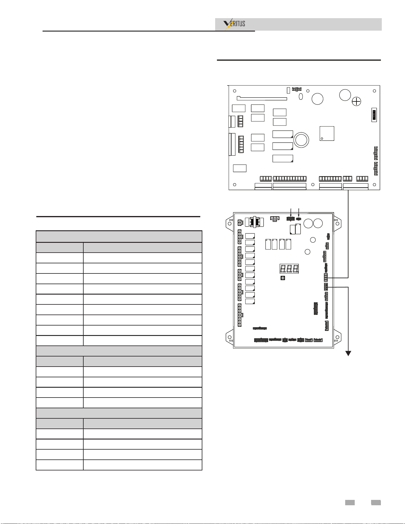
7 Field Wiring (continued)
Installation & Operation Manual
System Control
Heat Pump 1
J27
Heat Pump 2
J11
J27
J7
J3
J4
J5
J28
J15
J29
J16
J25
J20
J14
J1
J19
J11
J8
J17
J9
J2
J6
J24
J23
J18
J10 J13
J26
J22
Figure 7-4 Cascade Connections
Table 7-1 Cascade Connections
SCB Connection J11
PIN DESCRIPTION
1 DGND
2 RS485-B
3 RS485-A
4 DGND
5 RS485-B
6 RS485-A
7 DGND
8 RS485-B
9 RS485-A
HPC Connection J27
PIN DESCRIPTION
1 DGND
2 -
3 RS485-A
4 RS485-B
HPC Connection J7
PIN DESCRIPTION
1 DGND
2 -
3 RS485-A
4 RS485-B
Communication between water heaters is accomplished by
using the shielded, 2-wire twisted pair harness that is provided.
This harness will connect the system control board (SCB) to
the first heat pump control board (HPC), and then connect
every subsequent heat pump control board (HPC) in the
cascade. Use the provided Belden 9322 wire suitable for wet
environments or similar. Begin by connecting the twisted pair
cable to J11 on the SCB. There are three RS485 communication
ports available here. See below table for pin description. From
J11 on the SCB, route the other end of the cable into the side of
the 1st heat pump. Route the cable through the side of control
panel to connection J27 on the HPC. See below table for pin
description. If there are subsequent heat pumps in the cascade,
route another cable from J7 of the 1st heat pump, out the other
side of the unit, into the side of the next unit and connect to
J27 of the 2nd heat pump. Repeat for the total number of heat
pumps in the cascade. The connections between heaters can
be made in any order, regardless of the addresses of the water
heaters. Try to keep each cable as short as possible.
47
47
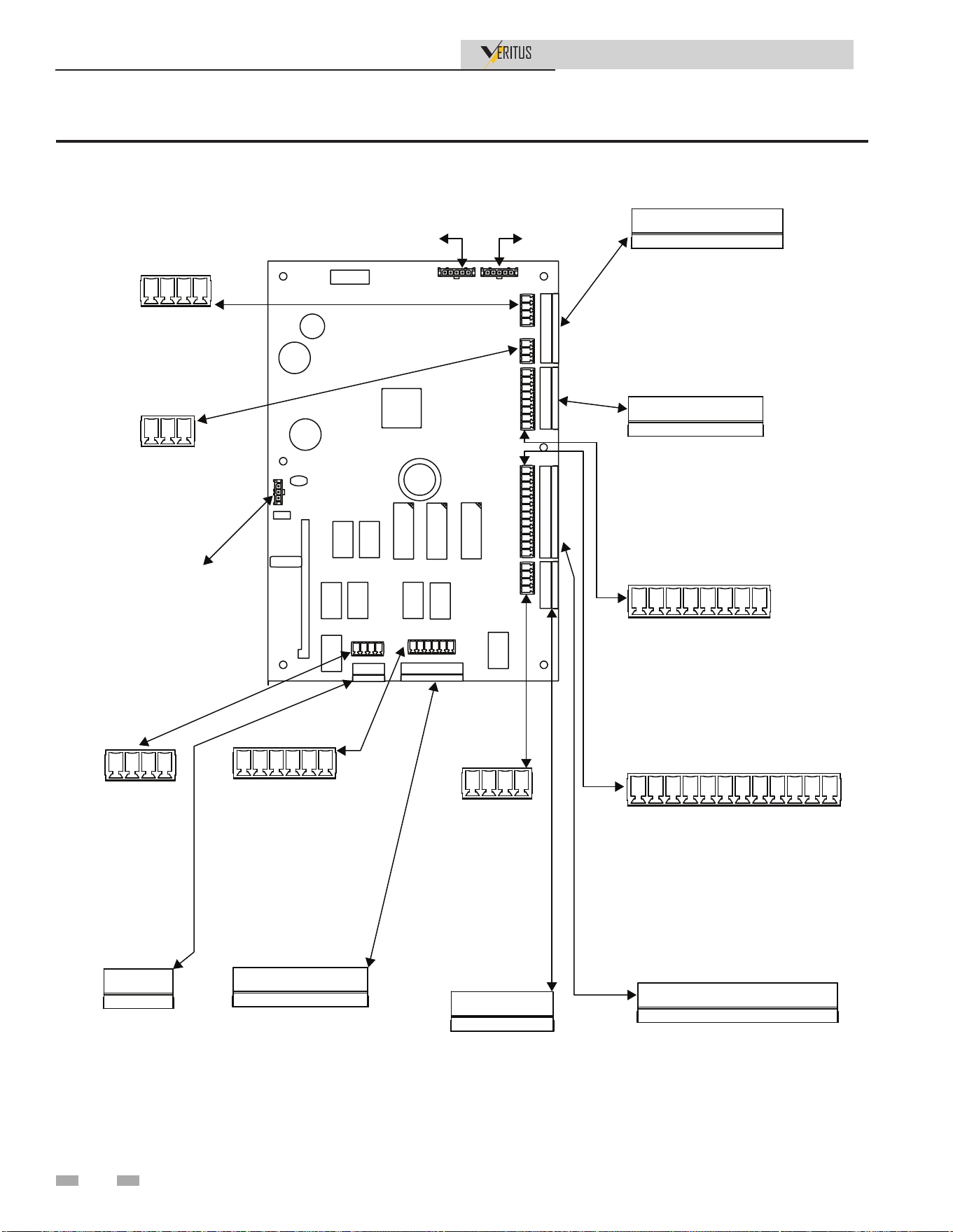
7 Field Wiring
Installation & Operation Manual
Figure 7-5 System Control Board Wiring Connections
J3 TEMP SENSORS
GND
TANK 1
GND
TANK 2
GND
TANK 3
GND
TANK 4
GND
TANK 5
GND
TANK 6
J2 DIGITAL IN
GND
ENABLE
--
--
GND
BMS ENABLE
J13 RELAY OUTPUT
24VAC-N BACKUP HEAT1
24VAC-L BACKUP HEAT1
24VAC-N BACKUP HEAT2
24VAC-L BACKUP HEAT 2
24VAC-N ALARM
24VAC-L ALARM
24VAC-N RUNTIME
24VAC-L RUNTIME
J11 CASCADE
RS485_GND
RS485_B
RS485_A
RS485_GND
RS485_B
RS485_A
RS485_GND
RS485_B
RS485_A
J14 PUMP RELAYS 1
24VAC-N RECIRC PUMP
24VAC-L RECIRC PUMP
24VAC-N PUMP2
24VAC-L PUMP2
J18 ANALOG IN
BMS 0-10V (+)
BMS 0-10V (-)
--
--
--
--
--
--
J4 PUMP RELAYS 2
24VAC-N PUMP3
24VAC-L PUMP3
24VAC-N PUMP4
24VAC-L PUMP4
J1 ECOPORT
GND
RS485_B
RS485_A
J5 RELAY OUTPUT
24VAC-N LOUVER
24VAC-L LOUVER
24VAC-N MIX VALVE CLOSE
24VAC-L MIX VALVE CLOSE
24VAC-N MIX VALVE OPEN
24VAC-L MIX VALVE OPEN
J20 TEMP SENSORS
GND
SYSTEM SUPPLY
GND
SYSTEM RETURN
GND
RECIRCULATION
GND
OUTDOOR
GND
AUX1
GND
AUX2
J7 PC
PC_GND
PC_B
PC_A
PC_+5V
J10 ANALOG OUT
DGND
--
DGND
BACKUP 1 OUT
DGND
BACKUP 2 OUT
--
--
J22 DIGITAL IN
LOUVER PROVING
GND
--
--
DISPLAY
NFC KEY
24VAC
48

8 Installation Checklist
Installation & Operation Manual
The list below represents some of the most critical installation
requirements that, when overlooked, often result in operational
problems, down time and needless parts replacement. This is
not a complete list. Before performing any troubleshooting
procedures use the list below to check for installation errors.
Costs to correct installation errors are not covered under the
limited warranty. Ensure all installation requirements and
instructions in this manual have been followed.
Location
Air Flow & Ducting
Water Piping
Condensate Drain
Electrical
1. Ensure the HPWH is located where there is a adequate
supply of ambient heat for optimal performance or that
the HPWH is ducted to such a location.
2. Ensure required clearances are maintained and there is
access for servicing. See Clearances on page 18.
3. Ensure the HPWH is properly supported.
4. Ensure all supply and return ductwork connected to the
HPWH is properly sized, does not exceed maximum
equivalent length requirements. Consult the factory for
sizing.
5. Ensure all supply duct work is insulated to prevent
condensation from forming on the ductwork.
6. Ensure all return air duct is insulated if the return air
temperatures are expected to fall below the surrounding
room air temperature during normal operation.
7. Ensure the outlet (supply) and inlet (return) water piping
connected to the HPWH are not less than the connection
size on the unit.
8. The unit pumps will perform best if check valves are not
installed between the heat pump outlet and tank unless
required by code on the system diagrams. The ball valve
internal to the unit can prevent hot water short circuiting.
9. When the HPWH is connected to a storage tank ensure
the storage tank is equipped with a properly rated and
sized Temperature and Pressure (T&P) relief valve.
Refer to the storage tank manufacturer’s instructions
for T&P valve sizing and installation requirements.
Note: This is a critical installation requirement that must
not be overlooked. Call the toll free technical support
phone number 1-800-722-2101 for further assistance.
10. DO NOT install a T&P valve in the outlet (supply) water
line of the HPWH unless required by local code.
11. Ensure isolation valves are installed on the HPWH supply
and return water line at the storage tank for servicing and
purging the air from the HPWH during start-up.
12. Tee into the inlet of the HPWH, but in some cases
piping directly to the tank is possible. See the Service and
Installation Notes for Inlet & Outlet Water Temperature
on page 25.
13. Connect building recirculation loop piping to the
backup water heater inlet on two tank preheat piping
configurations.
14. Ensure the building recirculation loop pump is controlled
by a field supplied line thermostat and that it stops
the pump when the recirculation line temp exceeds the
manufacturer’ specifications.
15. The manufacturer recommends installing a strainer at the
inlet water line on the HPWH to help prevent scale build
up in the heat exchanger. Service costs to clear blockages
from the HPWH unit’s heat exchanger due to debris are
not covered under the limited warranty.
16. Ensure there is a water trap installed in the condensate
line at the HPWH. Condensate will not drain without a
water trap.
17. Ensure the condensate drain is properly connected to
the HPWH and draining freely to a suitable floor drain
or condensate lift pump that discharges condensate to a
remote location. See Condensate Drain Line on page 25.
18. BEFORE ENERGIZING THE UNIT ensure the power
supply voltage and phase matches the requirements on the
HPWH rating label. Damage resulting from applying the
wrong voltage or phase is not covered under the limited
warranty.
19. Ensure the power supply breaker or the fuses disconnect
switch are within the requirements for the unit as shown
on the HPWH rating label.
20. Ensure the power supply wiring meets the MCA (Minimum
Circuit Ampacity) requirements shown in this manual and
on the HPWH data label.
21. Ensure the HPWH is properly grounded according to the
instructions in this manual and local code requirements.
22. Ensure the power supply connections to the HPWH are
connected properly and securely tightened.
23. Ensure all electrical connections in the HPWH control
panel are securely tightened.
24. When the factory supplied temperature sensor is used:
• Insure the sensor is installed properly.
• Ensure the temperature sensor has been installed in a
designated temperature control opening in the mid/
lower portion of the storage tank.
• Ensure the supplied temperature sensor is coated with a
suitable heat transfer compound (paste).
49
9 Start-up
Installation & Operation Manual
3 Phase Start-Up Procedures
1. Make sure the disconnect is off and confirm there is no
power on the distribution block on the electrical panel.
2. Pull the unit fuses from the fuse block in the back panel
of the unit.
3. With disconnect back on, check and make sure the
power at the distribution block is the same as the power
requirements on the data sticker that is on the electrical
panel.
4. Turn power off and reinstall fuses.
Final checks before starting the water
heater
q Read the Veritus Water Heater Service Manual to familiarize
yourself with SMART TOUCH control module operation.
Read the preceding Start-up sections in this manual, for
proper steps to start the appliance.
q Verify all the pre-check procedures have been completed.
q Verify the appliance and system are full of water and all
system components are correctly set for operation.
q Verify electrical connections are correct and securely
attached.
q Inspect vent piping and air piping for signs of deterioration
from corrosion, physical damage, or sagging. Verify air
piping and vent piping are intact and correctly installed per
this manual.
Check system and water heater
q Check water piping
1. Check system piping for leaks. If found, shut down the
water heater and repair immediately. (See WARNINGS
on pages 62 and 63 (start-up) regarding failure to repair
leaks.)
2. Check Delta T. Reference Section 4 - System Piping of this
manual for more information regarding Delta T.
3. Vent any remaining air from the system using manual
vents. Air in the system will interfere with circulation and
cause heat distribution problems and noise.
q Check vent ducting and air piping.
1. Check seal at every connection, seam of air piping, and
vent piping.
Check/control Water Chemistry
See the following table for properly operating the water heater
with the appropriate water chemistry. Good water quality will
help extend the life of the appliance by reducing the effects of
scale buildup and corrosion.
NOTICE
Conduct water quality testing prior to
installing the appliance. Various solutions
are available to adjust water quality.
Table 9-1 Water Chemistry
WATER CHEMISTRY
Specication Range Requirement
Hardness
< 5 gpg
Follow
recommendations
detailed below (See
Notice 3)
> 15 gpg
Water softening system
required (See Notice 4)
Dissolved
Solids
< 350 ppm
Hardness level must
be met
pH Level 6.5 to 9.0
Acceptable range
Chloride < 150 ppm
Acceptable range
NOTICE
1. Do not use the water heater to directly
heat swimming pool or spa water.
2. At initial fill and during water heater
start-up and testing, check system
thoroughly for any leaks. Repair all
leaks before proceeding further.
3. When water hardness levels are less
than 5 gpg or 85.5 mg/l, the following
is recommended:
a. Flush and clean existing water heating
system prior to installation.
b. Inspect and, if necessary, replace the
anodes in any existing tanks.
c. Install a Y-strainer on the inlet of each
water heater as detailed in Section 7.
d. Limit the run time of the hot water
recirculation loop.
e. Filter the hot water recirculation loop
to a level of 10 microns. CAUTION:
Check recirculation pump size to
verify it is sized for filter addition.
4. When water softener is required, a
Template Assisted Crystallization
system is recommended.
50

9 Start-up (continued)
Installation & Operation Manual
Initial Start-up
1. Before applying power, check all electrical connections.
Tighten if necessary.
2. Verify electrical installation. Power requirements and
branch circuit disconnecting must match equipment
nameplate specifications.
3. Make sure the system is flushed and purged of air.
Remove and clean any strainers or filters if necessary.
4. Make sure the sensor for the temperature control is
securely mounted in the water tank bulbwell for proper
temperature control.
5. Start the heat pump by turning the switch in the high
voltage box to the ON position.
6. The crankcase heater is powered when the unit power
is turned on, and should be on for 4 to 6 hours before
allowing the compressor to start.
7. Double check to make sure all the air is out of the water
line so the heat pump doesn’t get air bound.
8. Pump Test – You should be able to hear the water flowing
through the system. If not, there is a good chance the
system is air bound and the air needs to be removed before
starting the compressor.
⚠CAUTION
⚠CAUTION
OIL DILUTION! Bearing malfunction! It is
important to ensure that new compressors
are not subjected to liquid abuse. Turn
the crankcase heater on 4 - 6 hours before
starting the compressor.
High discharge pressure operation!
Compressor damage! Do not use compressor
to test opening set point of high-pressure
cutout. Bearings are susceptible to damage
before they have had several hours of
normal running. Liquid and high pressure
loads could be detrimental to new bearings.
It is therefore important to ensure that new
compressors are not subjected to liquid
abuse and high-pressure run tests.
Commissioning Mode
Upon the initial startup, each heat pump will be forced to
step through a three-step commissioning sequence to help
ensure proper installation and operation. Each step must be
acknowledged by the user by holding the button on the unit
control box for 5 seconds. The three-character LED on the heat
pump control board will display SR1, SR2, or SR3 depending
on which step of commissioning mode is currently active.
1. SR1 - System Prime – The water valve will be set to fully
open without the pump running. This is to help charge
water to the system and remove any air.
2. SR2 - Manual Flow – The pump will run at the highest
flow set point. The flow rate cannot be changed during
commissioning. Check for any system water leaks.
3. SR3 - Manual Run – Water heating will be requested,
and the unit will run at 160°F (71°C). Verify proper
temperatures and pressures.
After advancing past step three, the unit will be set to normal
operation.
3. For more than one unit, an additional communication
cable will need to be installed between the 2 units, so the
system board inside the display panel can communicate
with all HPWHs linked together. This harness will be
provided if HPWH’s are positioned next to each other up
to 12 inches apart.
4. Display control panel houses the system control board that
has connections for up to 6 tank sensors. Install the tank
temperature sensors in a designated temperature control
opening in the mid/lower portion of the storage tank.
5. Use a suitable heat transfer compound on the probe to
ensure an accurate temperature reading.
6. Check the voltage into the terminal block and make sure
that it is 120V before applying power to the display panel.
Display Panel Startup
1. Display control panel can be mounted on the side of the
unit or in an equipment room (maximum distance from
heat pump is 1,500 feet), and requires a 120VAC single
phase 60 hertz power source.
2. Connect the communication harness to the system board.
This cable runs from the display panel to the control
panel inside the HPWH control panel in the unit. This
communication harness will be provided in a length that
will connect if the display is mounted to the side of the
unit, but for installation that require longer harnesses
connectors will be provided to make the harness the length
needed.
51

9 Start-up
Installation & Operation Manual
Starting Sound
During the very brief start-up, a clicking sound is audible,
resulting from initial contacting of the spirals and is normal. No
start assist devices are required for three-phase compressors,
even if a system uses non-bleed expansion valves. Due to
the design of the Copeland Scroll, the internal compression
components always start unloaded even if system pressures
are not balanced. In addition, since internal compressor
pressures are always balanced at start-up, low voltage starting
characteristics are excellent for Copeland Scroll™ compressors.
Moreover, if low voltage conditions exist at start up, protector
trips could result.
Start-up
This start-up refers to several tools and test instruments
needed to complete the procedure. See Required Tools and
Materials on page 23.
1. Ensure the Installation Checklist has been completed.
2. Ensure the HPWH, storage tank and water system has
been purged of air and all valves are in the position for
normal operation.
3. Turn on power at the circuit breaker or disconnect switch
serving the HPWH.
4. Turn the power switch on inside the display panel to monitor
the refrigerant pressures, the inlet water temperature, and the
outlet temperatures to ensure water temperature is rising.
NOTE: It may be helpful to record the operating data
initially every 10 to 30 minutes just to see how the heat
pump is performing.
5. The factory temperature setting is 120°F. Refer to page 54
for adjusting setpoint. (This can be adjusted later as well,
NEVER SET HIGHER THAN 160°F).
6. The unit is equipped with inlet and outlet water
sensors. There values will be displayed on the display
screen. Ensure the water outlet (supply) and inlet
(return) valves are fully open. Start the HPWH and
allow it to operate for 5 minutes. with the HPWH
operating record the inlet and outlet temperatures.
During normal operation, the outlet line should be 8°F to
120°F (4°C to 67°C) hotter than the inlet line. This is the
temperature rise through the heat exchanger inside the
HPWH unit. Note: Temperature rise and water flow rate
through the heat exchanger inside the HPWH are uniformly
linked. As water flow is decreased the temperature rise will
increase and as water flow is increased the temperature
rise will decrease. Because of this relationship between
temperature rise and flow rate this test can be useful to
determine if the flow rate through the heat exchanger is
adequate. Other factors may also affect water flow rate
and temperature rise such as debris or lime scale build
up inside heat exchanger or water pump operation.
If the temperature rise through the HPWH is consistently
lower than 8°F, check the display screen to verify flow. If
the temperature rise continues to be excessive call the toll
free technical support phone number: 1-800-722-2101.
Rotation Direction
Scroll compressors, like several other types of compressors,
will only compress in one rotational direction. Three-phase
compressors will rotate in either direction depending upon
phasing of the power to L1, L2 and L3. Since there is a 50/50
chance of connecting power in such a way as to cause rotation
in the reverse direction, it is important to include notices and
instructions in appropriate locations on the equipment to
ensure proper rotation direction is achieved when the system is
installed and operated. Observing that suction pressure drops
and discharge pressure rises when the compressor is energized
allows verification of proper rotation direction. There is no
negative impact on durability caused by operating three-phase
Copeland Scroll™ compressors in the reversed direction for a
short period of time, (under one hour), but oil may be lost.
After a few seconds of operation in reverse, the compressor
Core Sense system will lockout due to reversed phase. However,
if allowed to repeatedly restart and run in reverse without
correcting the situation, the compressor will be permanently
damaged. All three-phase Scroll compressors are identically
wired internally.
If the CoreSense locks out with a compressor reversed phase
fault, switch two legs of incoming 480VAC power at the main
connections into the HPWH at the rear of the unit.
52

If the HPWH does not start immediately:
• Wait 10 minutes in case the anti short cycle timer has
halted operation. This control system feature protects
the HPWH from rapid short cycling that can cause
permanent damage to the unit.
• Ensure the operating set point on the tank temperature
control is adjusted high enough to initiate a call for
heat.
• DO NOT set the operating set point on the tank
temperature control above 160°F. See Water
Temperature Range on page 14.
• Ensure the differential set point is not set too
high. Higher differential settings will cause greater
temperature swings in system temperature. Lower
differential settings can cause unit short cycling. The
recommended setting is 10°F.
• If the unit does not start after all of the above procedures
have been followed. Refer to the troubleshooting
section of this manual.
9 Start-up (continued)
Installation & Operation Manual
7. Using thermometers or temperature sensors, measure
the temperature of the return (inlet) air to the HPWH
and the supply (outlet) air leaving the unit. The outlet
air temperature should be 12°F to 20°F (7°C to 11°C)
cooler than the inlet air. Air temperature and flow rate
through the heat pump determines what this temperature
difference will be. The higher the flow rate the lower
the temperature differential will be. The higher the
air temperature, the higher the differential will be.
If the temperature differential between return and supply
air is not within the range stated above ensure the air
filters are clean and there is nothing blocking the air flow
on either side of the air stream or ductwork attached to
the HPWH. Ensure the ductwork is not smaller than the
minimum required size and or longer than the maximum
length allowed in the Air Flow & Ducting section of
this manual. Ensure the evaporator coil is not damaged
(fins flattened) or dirty. If the temperature differential
continues to be outside the range mentioned above call the
toll free technical support phone number 1-800-722-2101
for further assistance.
8. When all of the above procedures are complete adjust
the tank temperature control set point to desired system
temperature, not to exceed 160°F (71°C). Remove all test
instruments and replace all cabinet door.
53
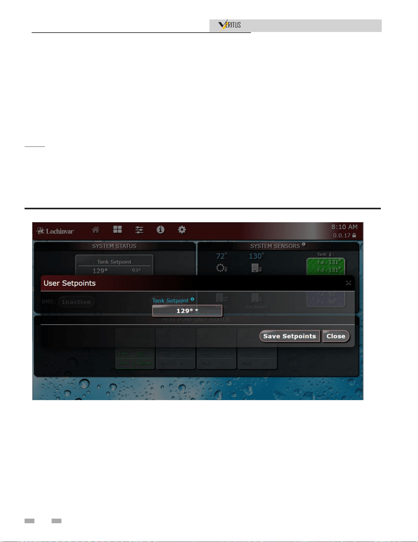
9 Start-up
Installation & Operation Manual
Adjust set point temperature(s)
During normal operation, set point temperatures can be
adjusted from the Home Screen by pressing the SETPOINT
button in the middle of the screen (see FIG. 10-1).
1. To change a set point, use the pull down list to adjust the
set points as shown in FIG. 9-1.
2. Once the set point has been adjusted to the desired setting,
press the SAVE SETPOINTS dialog box (right).
Set clock and date
The SMART TOUCH control has a built-in clock that it uses
for logging events. This clock must be set when the appliance
is installed and anytime the appliance has been powered off for
more than four (4) hours. Use the following procedure to set
the clock:
1. Press the SETTINGS button (gear icon) at the top center
of the screen (see Figure 9-1).
2. Press the SET APPLIANCE TIME button, then press SET
MANUAL TIME.
3. Deselect automatic date and time at the top section of the
menu.
4. Proceed to set the date and time.
5. Press the triangle navigation button on the bottom of the
screen to exit this menu.
Figure 9-1 User Set Point Screen
NOTE: The SAVE SETPOINTS dialog box must be pressed
to complete programming of the controls. Failure to press the
SAVE SETPOINTS dialog box will result in an unprogrammed
control. The Door Menu button will become highlighted when
there are changes that can be applied.
3. Follow the same steps to set the tank temperature
(Figure 9-2).
54
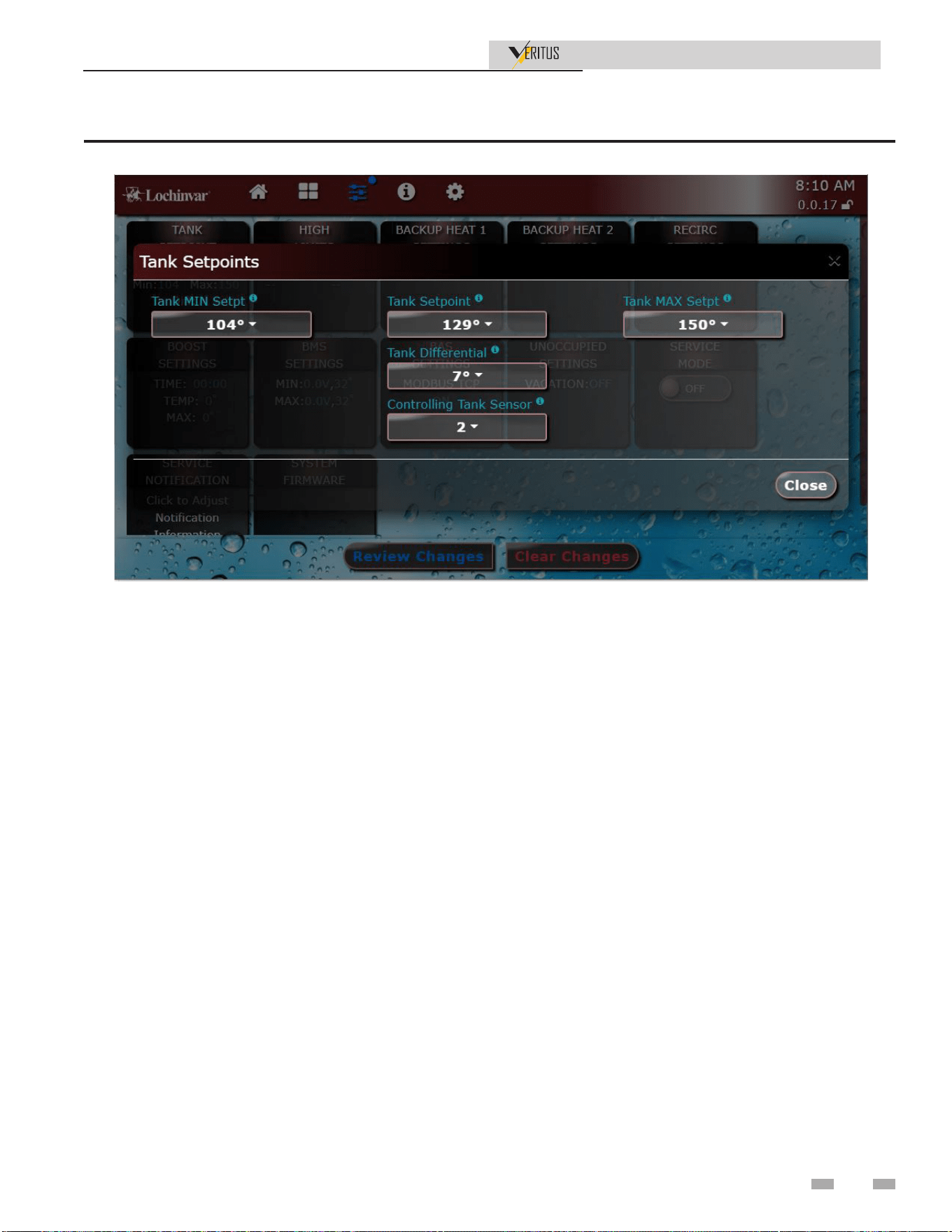
9 Start-up (continued)
Installation & Operation Manual
Configuration of the cascade
Configuration of the cascade will happen automatically on start
up. The system control board will assign addresses to each unit
on initial startup. This will enable cascading of the heat pumps.
Figure 9-2 User Set Point Screen
55

10 Operating Information
Installation & Operation Manual
General
How the water heater operates
The Veritus water heater uses a scroll compressor to compress
low pressure vapor refrigerant to a high pressure vapor state.
The high pressure vapor is passed through a brazed plate heat
exchanger along with cold water that passes through the heat
exchanger in channels flowing in the opposite direction. The
heat from the refrigerant is used to heat up the water and
refrigerant returns to a liquid state. The amount of the liquid
refrigerant flow is metered by electronic expansion valves
(EEVs) as it enters 2 evaporators where air forced through the
evaporators heats the refrigerant enough to change it back into
a vapor. The vapor refrigerant returns to the compressor where
the cycle starts over.
Control inputs and outputs
Enable / tank sensor
Both Enable and Tank Sensor inputs are used to call for heating
from the water heater.
0 - 10VDC input (set point)
The Veritus water heater can be controlled by a Building
Management System (BMS) using a 0 - 10 VDC signal. The
control can be configured by the installer to use this signal to
either control set point. This signal can be sent to the heater
through ModBus as well.
Temperature control
Water Flow
The Veritus water heater water flow is controlled to produce
water to a given set point. The flow will vary as water
temperature, ambient air temperature and set point change.
Protection features
Outlet temperature, ambient temperature,
and refrigerant pressures
The outlet temperature is monitored by the water heater outlet
temperature sensor. When the outlet temperature exceeds
167°F, the control will shut the unit down until the temperature
drops 5°F.
The control module monitors the air temperature by a sensor
located inside the unit. As the air temperature rises the control
module reduces the fan speed. When the air temperature
exceeds 120°F the control will shut the unit down. The unit will
restart automatically once the air temperature drops 10°F (6°C)
and the minimum off time has expired.
The refrigerant pressures are monitored at the suction and
discharge pipes of the compressor. The discharge pressure
switch opens at 400 psig shutting the compressor off, and when
the pressure drops to 280 psig or lower, the switch closes to
allow the compressor to run. Low pressure is limited on the
inlet or suction side of the compressor. If the pressure drops to
5 psig, the switch opens and the compressor shuts off. When
pressure reaches 20 psig on the line, the switch closes and the
compressor is once again allowed to run. The compressor will
also lockout at a high temperature on the discharge of 250°F.
For operation to be allowed to resume the temperature must
cool down for 20 minutes. If the refrigerant manages to reach
the hard lock out temperature of 275°F, the oil will break down
and must be replaced. The 140K unit Core Sense Module has a
hard lockout at 260°F to prevent oil damage, but this feature is
not available on the 60K unit.
Defrost
In low ambient temperatures, the unit has the ability to reverse
refrigerant flow using the 4-way valve. There are sensors
located on the evaporators that allow the unit to know when
defrost is needed. When this occurs, the 4-way valve directs the
hot refrigerant from the compressor straight to the evaporators
reversing the flow. When the evaporators have reached the
desired temperature that indicates all frost has melted, the fan
runs for a short amount of time to allow things to dry. Once
this time has elapsed the 4-way valve switches positions and
the unit goes back to normal operation.
Vacation Mode
This mode is used to reduce temperature setpoint by the
vacation offset while the building is not occupied. If enabled
the tank setpoint temperature will be reduced by the amount
specified by the Vacation Offset Temperature.
If Vacation mode is active an icon on the home screen
will appear under the tank setpoint location with the word
VACATION.
Night setback
Night Setback allows tank temperatures to be offset (lowered)
during periods where the building is either unoccupied or
seasonal use allows lower temperatures. Twelve schedules will
allow the user to customize systems to maintain comfort while
conserving energy during low-demand periods. From this
screen you can enable/disable by pressing the enable check box
for the listed schedule. If a schedule is active, an icon on the
home screen will appear under the tank setpoint location with
the words NSB#, where # is the active schedule. Night Setback
Schedules can be added or edited by pressing the Edit Schedule
Icon or Add Schedule button. Toggle through the month, days,
days of the week, and time to set the schedule.
56

Short Cycling
The Veritus heat pump has a built in “Anti-Cycle” to protect
the compressor from starting too frequently. The compressor
should remain off for at least three minutes after any period
of running. Each unit will remain in “Anti-Cycle” state
until this three minute timer has been cleared. The current
state, including “Anti-Cycle,” can be seen on the display by
navigating to the individual heat pump information screen.
10 Operating Information (continued)
Installation & Operation Manual
Neither this feature nor the water heater control module
eliminates the possibility of freezing. The installation must still
use recognized design, installation, and maintenance practice
to prevent freeze potential for the appliance and system.
The Freeze Protection feature will not work if the appliance
does not have power, is locked out, is in shutdown mode, had a
component failure, or is otherwise prevented from firing.
Water heater temperature regulation
Operating temperature (target)
The SMART TOUCH control module senses water temperature
and regulates water water and air flow to achieve a target
temperature. The target temperature can be set between 120°F
and 160°F.
High limit operations
The Veritus water heater is equipped with an automatic reset
high limit and a manual reset high limit. The automatic reset
high limit has a set point of 185°F from the factory and the
manual reset high limit has a maximum set point of 200°F.
When the outlet temperature exceeds 170°F, the automatic
high limit action occurs. The water heater shuts down until
the outlet water temperature cools below 165°F, and a 60
second timer has expired. If the outlet temperature continues
to increase, then the manual reset high limit switch action will
occur at 203°F.
Runtime and alarm outputs
The water heater provides dry contacts for indicating when the
water heater is running, and when it is unable to operate.
Runtime and cycle counting
The control uses a timer to monitor the total hours of unit
operation. The timer monitors the time the water heater is on.
The control uses a counter to monitor the amount of water
heater cycles. The first counter counts compressor power on
cycles.
Service reminder
The control can be programmed for service reminder
notification. This notification will become active when either
a set amount of time has expired, or a set amount of running
hours or cycles has expired (all adjustable by the installer).
The display will show a Maintenance Required screen. The
installer’s name and phone number can be programmed into
the control. This information will appear on the Maintenance
Required screen. The service reminder notification can be reset
or disabled by the installer.
The time dependent feature has been disabled by the
manufacturer. To enable this feature change the parameter to
the desired time interval, reference the Veritus Service Manual
for details regarding parameters.
Error logging
The control will hold in memory the last 10 lockouts as well as
the last 10 blockings. The date and time of the occurrence will
be recorded as well. Only the 10 most current occurrences of
each will be held in memory.
Freeze protection
These units can be installed in conditions below 32 F. With
power to the heat pump, the unit will circulate approximately
1.5gpm water flow through the system for freeze protection.
Additionally, there are electrical heat trace cables on the water
inlet pipe, condenser, and evaporator drain pan to aid in ice
prevention.
⚠ DANGER
Freezing Conditions: If this appliance may
have been exposed to freezing conditions
with no power, do not start the unit. Shut
off power and water to the appliance
immediately and contact the factory for
further instructions. Allowing the appliance
to start when the heat exchanger or near
water heater piping is frozen will result
in death or serious injury, and significant
property damage.
The following integral feature of the appliance control module
provides some protection for the appliance only -- not for the
system.
The water heater control module provides freeze-up protection
as follows:
• Below an inlet or outlet temperature of 40°F (4.4°C), the
water heater pump operates constantly.
• Water pump will turn off if water inlet or outlet temperature
rises above 45°F (7°C).
57

10 Operating Information
Installation & Operation Manual
Cascade
When multiple water heaters are installed, they can be wired
together in a cascade sequence. Multiple water heaters can be
controlled from a single control. The system control board
located in the display panel box will control all heat pumps
to run in an optimized order to give all heat pumps an equal
amount of run time.
Once the heat pump water heater receives a call for heat
from a tank sensor or BMS, the control will determine what
the set point will be. A fixed temperature set point can be
programmed into the control. See page 54 of this manual to
program the set point.
If the water temperature at the tank is less than the set point -
differential, then the control will initiate a call for heat on the
Cascade (see the Veritus Water Heater Service Manual for an
explanation of the differential). The system control board will
energize a heat pump(s) in the Cascade.
Access modes
User
The USER can set the tank set point, turn the unit OFF and
ON, and set up Wi-Fi.
Installer
Most parameters are available only to the installer, accessible
by entering the installer password, see the Veritus Water
Heater Service Manual.
NOTE: The password will timeout after an hour from entry.
Sequence of the cascade
To equalize the runtime of all water heaters on the Cascade,
the operating sequence will automatically be changed at set
intervals.
For the first 24 hours after initializing the Cascade, the
sequence will be changed every hour. After that the sequence
will be changed once every 24 hours. For example, switching
on/off sequence will be as follows for 8 HPWHs in the cascade:
If a water heater locks out, a different unit will be turned on
instead.
Night Setback operation with cascade
Night Setback operation of the water heaters within the
Cascade is available. Programming of the Night Setback will be
done through the display. Refer to the Veritus Water Heater
Service manual for information regarding Night Setback.
Low water cutoff protection
1. The SMART TOUCH control module uses temperature
sensing of both supply and return areas of the heat
exchanger. If the flow rate is too low or the outlet
temperature too high, the control module shuts the water
heater down. This ensures water heater shutdown in the
event of low water or low flow conditions.
2. Some codes and jurisdiction may accept these integral
features of the control in lieu of requiring an additional
limit control or low water cutoff. Consult local jurisdiction
to determine.
58
10 Operating Information (continued)
Installation & Operation Manual
Sequence of operation
1.
Upon a call for heat, the control turns on the DHW pump.
2.
e control energizes the louvers (optional).
3.
e control conrms that the refrigerant high and low pressure switches, blocked drain switch, limits, louver
proving switch (optional), and contacts close.
4.
e control conrms the fan comes up to the desired speed.
5.
Once the fan is at desired speed, cycle is complete, the control lowers the fan speeds, initiates compressor,
and opens the water valve.
6.
Once the DHW call for heat is satised, the control will turn o the compressor. Any pumps that are running will
begin their respective Pump Delay cycles.
7.
At the end of the pump cycle, the louver relay contacts will de-energize.
8.
At the end of the Pump Delay cycle(s), the pump(s) will be turned o.
59
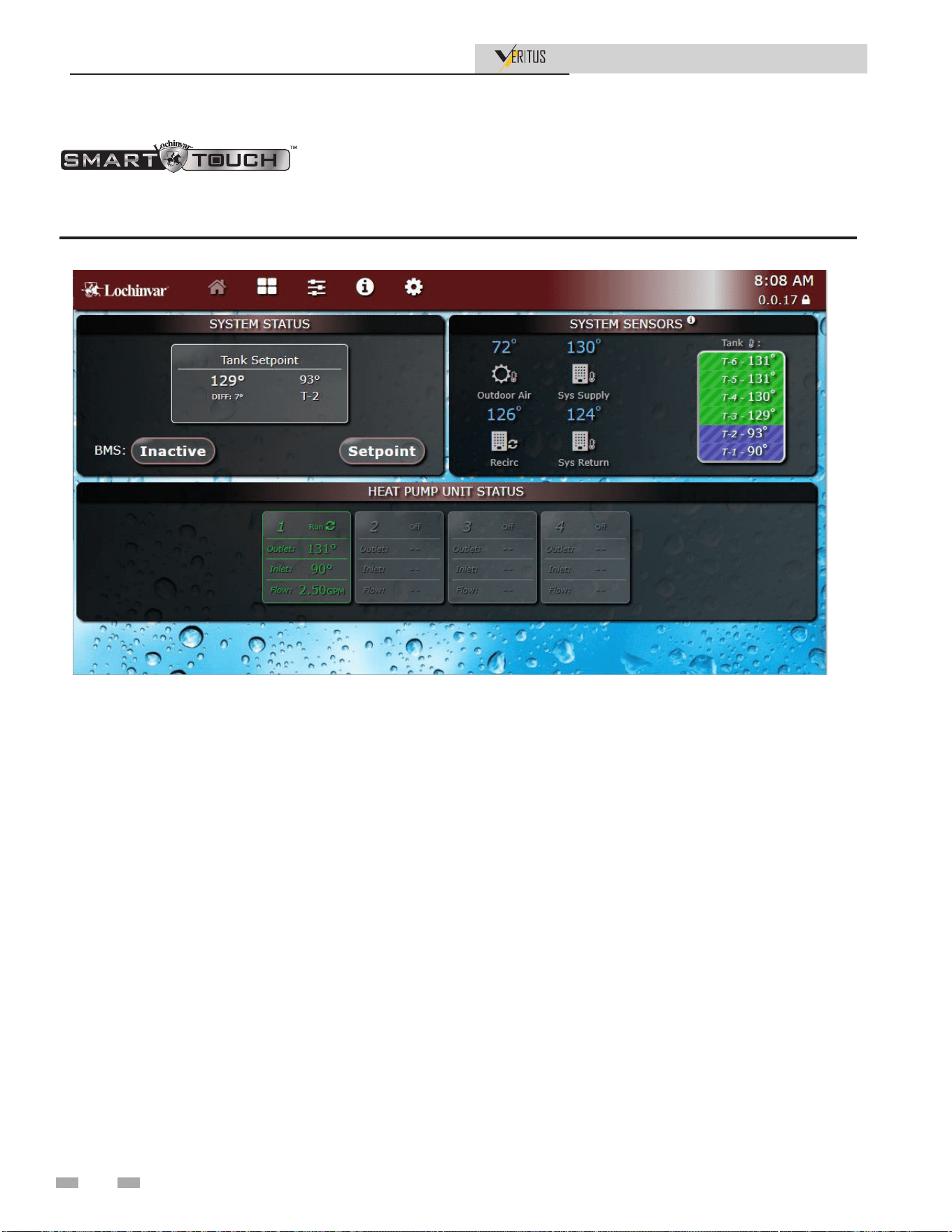
10 Operating Information
Installation & Operation Manual
Figure 10-1 Home Screen
The Home Screen displays basic information on how the unit is running. It is divided into the following sections: System Status,
System Sensors, Heat Pump Status, and Navigation.
• The System Status Section is located on the top left of the
screen and displays tank setpoints, BMS active or inactive,
and the setpoint button for adjusting setpoint.
• The System Sensor Section is located on the top right of the
screen and displays the outdoor air temperature, system
supply temperature, building recirc line temperature,
system return temperature, and 6 tank temperatures
(system may not required all 6 tank sensors).
• The Heat Pump Unit Status Section is located on the
bottom of the screen and displays operating information
on the heat pumps connected to the system. This can be up
to 64 heat pumps. Each heat pump block displays if the unit
is currently running (i.e. run, stand-by, blocking, lockout),
outlet temperature, inlet temperature, and flow rate in
GPM.
• The Navigation Section is located in the top portion of
the screen. There are five (5) sections located below the
Lochinvar icon: Home, View, Setup, Information (About),
and Settings. The Home Section is the screen shown
above. The View Section provides more detailed
information including subsections for: System Sensors,
Runtime, Faults, and System Details. The Setup Section
has several screens to aid in setting up the appliance. The
Setup Section includes screens for adjusting: Set Points,
BMS settings, Backup Heat Settings, Boost Settings,
BAS Settings, Service Mode, Service Notification, and
System Configuration. The Setting Section enables
several interface setup features including: Temperature
Units, Time Setup, WiFi Setup, Screen Settings, System
Updates, and Terminal Reboot.
60

11 Maintenance
Installation & Operation Manual
Maintenance and annual startup
Table 11-1 Service and Maintenance Schedules
Service technician
(see the following pages for instructions)
General:
• Address reported problems
• Inspect water heater area
• Inspect interior; clean and vacuum if
necessary;
• Check for leaks (water, air)
• Check water heater relief valve
• Check system water pressure/system
piping/expansion tank
• Check control settings
• Check wiring and connections
• Clean and inspect evaporators
• Check internal insulation
• Clean and flush condenser (brazed plate
hex)
• Check air flow
• Check refrigerant charge by viewing
temperatures, pressures, and superheat on
the Smart Touch control
• Check Delta T (Temperature Rise)
ANNUAL START-UP
Owner maintenance
Daily
• Check water heater area
Monthly
• Check air piping
• Check air and vent termination
screens
• Check relief valve
• Check drain system
• Check automatic air vents
• Check Delta T (Temperature
Rise)
• Remove debris from Y-strainer
per manufacturer’s instructions
• Check building recirculation
filter (if filter required)
• Check for and clean any debris
or obstruction from birdscreens
(if equipped)
Every
6 months
• Check water heater piping
(refrigerant and water) for leaks
• Check and clean drain pan
• Operate relief valve
• Check water chemistry
• Inspect fan blades
61

11 Maintenance
Installation & Operation Manual
Follow the service and maintenance procedures given throughout this manual and in component literature
shipped with the water heater. Failure to perform the service and maintenance could result in damage to the
water heater or system. Failure to follow the directions in this manual and component literature could result in
severe personal injury, death, or substantial property damage.
The water heater should be inspected annually only by a qualified service technician. In addition, the
maintenance and care of the water heater designated in Table 11-1 and explained on the following pages must be
performed to assure maximum water heater efficiency and reliability. Failure to service and maintain the water
heater and system could result in equipment failure.
Electrical shock hazard – Turn off power to the water heater before any service operation on the water heater
except as noted otherwise in this instruction manual. Failure to turn off electrical power could result in electrical
shock, causing severe personal injury or death.
Should the unit have to be serviced with live electricity, only trained and qualified technicians should carry out
the service. Failure to follow all of the safety warnings may result in serious injury or death.
Eliminate all system or water heater leaks.
Leaking water may cause severe property
damage.
⚠ WARNING
⚠ WARNING
⚠ WARNING
⚠ WARNING
⚠ WARNING
Check all piping for leaks
Address reported problems
1. Inspect any problems reported by the owner and correct
before proceeding.
Inspect water heater area
1. Verify that water heater area is free of any corrosive
materials.
2. Verify that air intake area is free of any of the contaminants
listed in Section 1 - Determine Water Heater Location.
If any of these are present in the water heater intake air
vicinity, they must be removed. If they cannot be removed,
reinstall the air and vent lines per this manual and the
Water Heater Service Manual.
Inspect water heater interior
1. Remove the front access cover and inspect the interior of
the water heater.
2. Inspect for oil on the components and base which could
indicate a refrigerant leak.
3. Vacuum any sediment from inside the water heater and
components. Remove any obstructions.
Air Ducting
1. Visually inspect the entire air venting system for blockage,
deterioration or leakage. Repair any joints that show
signs of leakage. Verify that the air inlet and outlet duct is
connected and properly sealed.
2. Verify that water heater air discharge and air intake are
clean and free of obstructions.
3. Verify that bird screens are clean and free of debris or
obstruction.
Check water system
1. Verify all system components are correctly installed and
operational.
2. Check the cold fill pressure for the system. Verify it is
correct (must be a minimum of 12 PSI).
3. Watch the system pressure as the water heater heats up
(during testing) to ensure pressure does not rise too high.
Excessive pressure rise indicates expansion tank sizing or
performance problem.
4. Inspect automatic air vents and air separators. Remove air
vent caps and briefly push valve to flush vent. Replace caps.
Make sure vents do not leak. Replace any leaking vents.
1. Inspect the condensate drain line, condensate PVC fittings,
and condensate trap.
2. Look for signs of leaking lines and correct any problems
found.
62

11 Maintenance (continued)
Installation & Operation Manual
Check expansion tank
Expansion tanks provide space for water to move in and out as
the heating system water expands due to temperature increase
or contracts as the water cools. Tanks may be open, closed or
diaphragm or bladder type. See Section 4 - System Piping for
suggested best location of expansion tanks and air eliminators.
Check relief valve
1. Inspect the relief valve and lift the lever to verify flow.
Before operating any relief valve, ensure that it is piped
with its discharge in a safe area to avoid severe scald
potential. Caution should be taken to ensure that (1) no
one is in front of or around the outlet of the temperature
pressure relief valve discharge line, and (2) the water
manually discharged will not cause any bodily injury or
property damage because the water may be extremely hot.
2. After following the above warning directions, if the relief
valve weeps or will not seat properly, immediately close
the cold water inlet to the heat pump, follow the draining
instructions in the storage tank manual, and replace the
relief valve with a new one. Ensure that the reason for relief
valve weeping is the valve and not over-pressurization
of the system due to expansion tank waterlogging or
undersizing.
Safety relief valves should be re-inspected
AT LEAST ONCE EVERY THREE YEARS,
by a licensed plumbing contractor or
authorized inspection agency, to ensure
that the product has not been affected by
corrosive water conditions and to ensure
that the valve and discharge line have not
been altered or tampered with illegally.
Certain naturally occurring conditions may
corrode the valve or its components over
time, rendering the valve inoperative. Such
conditions are not detectable unless the
valve and its components are physically
removed and inspected. This inspection
must only be conducted by a plumbing
contractor or authorized inspection agency
– not by the owner. Failure to re-inspect the
water heater relief valve as directed could
result in unsafe pressure buildup, which can
result in severe personal injury, death, or
substantial property damage.
⚠ WARNING
Following installation, the valve lever must
be operated AT LEAST ONCE A YEAR
to ensure that waterways are clear. Certain
naturally occurring mineral deposits may
adhere to the valve, rendering it inoperative.
When manually operating the lever, water
will discharge and precautions must be
taken to avoid contact with hot water and
to avoid water damage. Before operating
lever, check to see that a discharge line is
connected to this valve directing the flow
of hot water from the valve to a proper
place of disposal. Otherwise severe personal
injury may result. If no water flows, valve
is inoperative. Shut down the water heater
until a new relief valve has been installed.
⚠ WARNING
Check all water heater wiring
1. Inspect all water heater wiring, making sure wires are in
good condition and securely attached.
Check control settings
1. Set the SMART TOUCH control module display to
Parameter Mode and check all settings. See Section 1 of
the Veritus Service Manual. Adjust settings if necessary.
See Section 1 of the Veritus Service Manual for adjustment
procedures.
2. Check settings of external limit controls (if any) and adjust
if necessary.
Perform start-up and checks
1. Start water heater and perform checks and tests specified in
Section 9 - Start-up.
2. Verify cold fill pressure is correct and that operating
pressure does not go too high.
Review with owner
1. Emphasize the need to perform the maintenance schedule
specified in this manual.
2. Remind the owner of the need to call a licensed contractor
should the water heater or system exhibit any unusual
behavior.
3. Remind the owner to follow the proper shutdown procedure
and to schedule an annual start-up.
Read Section 4 - System Piping before proceeding further. If
you do not understand these instructions or have any questions
regarding the temperature-pressure relief valve call the toll free
number 1-800-722-2101 for technical assistance.
63
11 Maintenance
Installation & Operation Manual
Evaporator Cleaning and Inspection
Drain Pain
Warning: Read all of the warnings on the bottle of the cleaning
products used for drain pan cleaning. Follow all instructions
for personal protection and safe application of the products.
Before cleaning the drain pan, disconnect all power to the unit
and follow the prescribed lock-out/tag-out procedure.
The condensate pan and drain line must be checked for
cleanliness, growth, and blockage at least every six months. To
clean the drain pan, start by disconnecting the power to the
unit. Find a cleaner that is safe to use on ABS plastics. Wear
the appropriate personal protective equipment prescribed by
the cleaning product instructions. Apply the cleaning solution,
allow it to sit for prescribed amount of time, then rinse. Remove
any particles that could potentially block the drain line.
Braze Plate Cleaning Instructions
In some applications the heat exchanger may be subjected to
severe fluid conditions, including high temperature hard water
conditions, causing accelerated scaling and corrosion rates,
and will diminish performance.
It is important to establish regular cleaning schedules. A 5%
solution of Phosphoric Acid or Oxalic Acid may be considered.
Other types of solutions can be obtained from your local
wholesaler. Make sure cleaning solution is applicable for
stainless steel and copper and all directions are followed.
Do not heat solution. Be sure to flush heat exchanger with
fresh water after cleaning using flush valves provided with
manifolds. See Figure 11-1.
⚠ CAUTION
Direct stream of water should be avoided,
to prevent damage to evaporators. instead
using a fanned-out method.
1. Disconnect all power to the unit and follow the prescribed
lock-out/tag-out procedure.
2. Wear the prescribed personal protective equipment
prescribed from the cleaning product instructions.
3. Install a block-off sheet to prevent splash over into the dry
sections of the HPWH.
4. Prepare the cleaning solution as prescribed from the
cleaning product instructions and fill the mixture into a
high-pressure sprayer.
5. Start spraying both sides of the coil keeping the nozzle
perpendicular to the coil at least 6 inches from the coil face.
If the water pressure is questionable, observe the impact
of cleaning on a small section of coil before implementing
universally.
6. Thoroughly rinse the cleaned coil with cool, clean water.
7. Straighten out any fins displaced during the cleaning using
a fin comb.
8. Confirm the drain pan line is not clogged.
9. Replace all panels on the unit and wipe down any standing
cleaning solution or water on or around the unit.
Figure 11-1 Braze plate
Cleaning Internal Pipe Insulation
Inspect the internal pipe insulation on a yearly basis for any
microbial growth. The insulation never has to be cleaned unless
microbial growth is detected. If microbial growth is detected,
follow the removal steps below:
1. Disconnect all power to the unit and follow the prescribed
lock-out/tag-out procedure.
2. Wear the prescribed personal protective equipment
prescribed from the cleaning product instructions.
3. Remove as much dirt and organic material from the
insulation using a vacuum device with a HEPA filter
(99.97%) efficient at 0.3 micron particles). Be careful not to
tear the insulation during the cleaning procedure.
4. Apply the microbial cleaning agent as prescribed by the
application and usage instructions.
5. Allow the unit to dry thoroughly.
6. If necessary, apply an anti-microbial agent on the insulation
per the instructions provided on the product label. Discard
collected microbial contaminants as required by local or
state codes.
Read all of the warnings provided for the
cleaning products used for refrigeration coil
cleaning. Follow all instructions for personal
protection and safe application of the
products. Before cleaning the evaporator,
disconnect all power to the unit and follow
the prescribed lock-out/tag-out procedure.
⚠ WARNING
Inspect the evaporator coil for dirt buildup or fin crush on at
least once per year. If there are signs of fin fold over, use a fin
comb to straighten the fins. Should the coils need cleaning,
follow the steps listed below:
Warning: Read all of the warnings on the bottle of the cleaning
products used for evaporator cleaning. Follow all instructions
for personal protection and safe application of the products.
Before cleaning the drain pan or evaporators, disconnect all
power to the unit and follow the prescribed lock-out/tag-out
procedure.
64
11 Maintenance (continued)
Installation & Operation Manual
Inspecting Fan Assembly
Before performing any maintenance on the fan assembly,
disconnect all power to the unit and follow the prescribed
lockout/ tag-out procedure.
Allow time for fan capacitor dissipation
which takes a few minutes. Failure to wait
for capacitor to dissipate could result in
electrical shock, causing severe personal
injury or death.
⚠ WARNING
During inspection, visually check the blades for wear or
damage and replace as necessary. Inspect to confirm the center
hub bolt holding blades is in place, and tighten to 10 FT-LBS.
Clean the blades periodically as material buildup on the blades
can cause an imbalance that may lead to bearing failure. Every
six months visually inspect the fan motor. Clean off any dust,
grease or oily buildup and vacuum out any cavities in the
motor. Motors are permanently lubricated from the factory.
It is not necessary to lubricate the motor upon start-up or
lubricate as part of maintenance.
Check Air Flow
Correct any problems with air flow before checking the
refrigerant pressures.
Checking Refrigerant Charge
Servicing of the refrigeration circuit must only be performed
by agencies or individuals possessing Type II or Universal
certification as defined in Section 608 of the Clean Air Act. See
Qualifications on page 6.
This HPWH unit is factory charged with 513A refrigerant.
See the rating label on the HPWH unit and Table 11-3 for
refrigerant charge by weight. It should not be necessary to
add or remove refrigerant during installation or start up.
Refrigerant lost during frequent refrigerant pressure testing
can cause low refrigerant conditions. It is recommended that
pressures, temperatures, and superheat values be taken from
the smart control. Air and water flow should always be checked
first to eliminate other potential problems before checking the
refrigerant charge. Using gauges should be a last resort when
troubleshooting refrigeration issues.
Check Water Temperature
Always check water temperature rise through the HPWH
unit’s internal heat exchanger before checking the refrigerant
charge. See Start Up on page 50 for information on how to
measure the water temperature rise.
If the measured water temperature rise during start up is at
least 10°F (5.6°C) checking the charge is not necessary unless
other conditions warrant testing.
If the measured temperature rise through the HPWH unit is
less than 10°F (5.6°C) checking the charge is not necessary
unless other conditions warrant testing. Short water piping
runs between the HPWH and the storage tank will produce
lower temperature rises and are not problematic.
If the measured temperature rise is more than expected, check
for restrictions in the inlet and outlet water piping connected
between the HPWH unit and the storage tank.
Model Factory Charge R513A
AHP060 11.5 lbs
AHP140 15 lbs
Superheat
1. Use the display screen to record the ambient temperature
and measured superheat.
2. Use Table 11-2 to verify that superheat is in range for the
temperature.
3. Always refer to Smart Touch to monitor pressures,
temperatures, and superheat to prevent using gauges.
Table 11-3 Refrigerant Charge By Weight
Table 11-2 Superheat for Ambient Temperatures
Model 60K Model 140K
Temperature
Ambient (°F)
Superheat
(°F)
Temperature
Ambient (°F)
Superheat
(°F)
23 - 40 15 - 22 23 - 40 15 - 22
40 - 80 22 - 24 40 - 80 22 - 24
80 - 95 24 - 27 80 - 95 24 - 30
95 -120 27 - 30 95 - 120 30 - 35
To check if the system is low on refrigerant, check the
refrigerant pressures and compare it with the PT chart of 513A
(Table 11-4). If there is more than 10 psi difference between the
system pressures and saturated pressures, this might indicate a
loss of charge in the system. In case of low charge in the system:
1. Reclaim the refrigerant to a recovery tank if possible.
2. Pressure-test the system with an inert gas like Nitrogen
and monitor and system for leaks.
3. After pressure testing, pull a deep vacuum on the unit
(< 500 microns; 350 microns recommended). Ensure the
system holds the vacuum.
4. Weigh and charge the unit with the appropriate amount of
refrigerant. See table 11-3 for the recommended amount.
65
11 Maintenance
Installation & Operation Manual
Table 11-4 Saturated Temperature Chart
R513A SATURATED TEMPERATURE CHART
Saturated Temperature °F Saturated Temperature °C Saturated Pressure PSI
0 -18 9.1
5 -15 11.9
10 -12 15.0
15 -9 18.3
20 -7 21.9
25 -4 25.9
30 -1 30.1
35 2 34.6
40 4 39.6
45 7 44.8
50 10 50.5
55 13 56.5
60 16 63.0
65 18 69.9
70 21 77.3
75 24 85.1
80 27 93.4
85 29 102.0
90 32 112.0
95 35 121.0
100 38 132.0
105 41 143.0
110 43 155.0
115 46 167.0
120 49 180.0
125 52 193.0
130 54 207.0
135 57 222.0
140 60 238.0
145 63 254.0
150 66 271.8
155 68 289.9
160 71 308.9
66

11 Maintenance (continued)
Installation & Operation Manual
Problem Possible Causes Corrections
Heat Pump is too noisy
1. Sheet Metal fasteners are loose.
2. Operating vibration is transferring to
oor or building structure.
• Tighten Fasteners
• Place vibration dampers underneath
unit
Water on oor around the
heat pump and or water
tank
1. Tubing, valves, or ttings are leaking.
2. Heat Pump is not leveled causing
drain pan overow
3. Condensate trap not installed
properly
4. Drain pan overowing
5. Condensation forming on the bottom
of unit (humid environments)
• Repair leaks as necessary
• Shim unit to level, See installation
section
• Condensate trap depth must maintain
a water column during operation
• Use pipe snake or compressed air to
remove obstruction
• Cover bottom of unit with foam
insulation
Heat Pump is not running
- Electrical issues
1. Circuit does not have adequate
ampacity
2. Short circuit or loose connection in
eld wiring
3. Short circuit or loose connection in
the cabinet
4. Thermostat failure
5. Compressor burn-out
• Refer to nameplate for unit
requirements
• Check eld wiring diagram, Tighten all
connections
• Check for loose wiring and tighten
• Replace thermostat
• Replace Compressor
Heat Pump is not running
- High Pressure Fault
1. Thermostat setting too high
2. Air temperature over 120° F
3. Low water ow causes:
a. External Pump is not operating
b. Piping between the heat pump
and storage tank exceeds 500
equivalent feet
c. Heat exchanger has scale
buildup
d. Shut o valves are partially
closed
4. Faulty high pressure switch
• Thermostat setting should not exceed
160° F
• Keep heat pump o until room
temperature is back in operating range
• Low water ow corrections
• Replace unit pump
• Reduce piping or add booster pump
• Clean heat exchanger with a mild acid
wash
• Open all shut o valves
• Replace high pressure switch
Heat Pump is not running
- Low Pressure Fault
1. Room temperature below 23° F
2. Fan not operating at nameplate CFM
3. Flow though the evaporator is
restricted or blocked.
4. Unit does not have adequate
clearances obstructing air ow
5. Loss of Refrigerant
6. Faulty low pressure switch
7. Filer dryer restriction
8. EEV locked in closed position
• Keep heat pump o until room
temperature is back in operating range
• Correct air-ow issue
• Relocate unit to allow for even air ow
• Find source of leak, repair, and
recharge
• Replace low pressure switch
• Replace dryer lter
• Clean or replace EEV
Troubleshooting
67

11 Maintenance
Installation & Operation Manual
Troubleshooting continued
Problem Possible Causes Corrections
Water is not reaching
desired temperature
1. Thermostat setting is too low
2. Heat pump/storage tank undersized
for application
3. Heat pump is not properly connected
to storage tank
4. Unit cooling coil is over cooling the
space
• Set thermostat for storage tank to a
higher temperature
• Increase size of storage tank or install
gas or electric heater to make up for
shortfall
• Refer to eld piping diagrams for
recommended piping
• If the room air temperature is too cool:
a) Use back up water heating
b) Duct cool air to another space
c) Duct warmer air from another
space to the installed room
Evaporator coil is icing
1. Insucient air ow through the unit
2. Low air temperature
3. Partial refrigerant loss
4. Defective EEV valve
5. Clogged lter dryer
• Refer to “Heat pump not running
- low pressure fault” section for
correction suggestions
• If room air temperature is too cool
a) Use back up water heating
b) Duct cool air to another space
c) Duct warmer air from another
space to installed room
• Find source of leak
• Replace EEV valve
• Replace lter drier
*Reset the heat pump by removing then restoring power to the unit at the breaker, from the manual switch, or by pressing
and holding the button on the side of the control panel of the unit for 5 seconds. (There will be a three minute delay
before heat pump restarts.) If the heat pump cuts out again on LOW or HIGH PRESSURE, additional troubleshooting
is necessary to nd the cause.
DO NOT CONTINUE TO RESET THE HEAT PUMP, AS CONTINUED SHORT-CYCLING MAY STRESS OR DAMAGE
INTERNAL COMPONENTS.
68
12 Diagrams
Installation & Operation Manual
Figure 12-1 Ladder Diagram
BOX DEPICTS
OPTIONAL ITEMS
BOX DEPICTS
DUAL SENSOR
SINGLE HOUSING
WARNING
DISCONNECT POWER
BEFORE SERVICING
!
NOTES:
1. All wiring must be installed in accordance with: local, state, provincial and national code requirements per either N.E.C. in USA or C.S.A. in Canada.
2. If any original equipment wire as supplied with the appliance must be replaced, it must be replaced with wire having the same wire gauge (AWG) and rated for a minimum of 105°C.
Exceptions: Replacement shielded cables must be purchased from the factory. Use of a non-approved wire or cable can lead to operational problems which could result in non-repairable
damage to the integrated controller or other components.
3. Actual connector block locations may vary from those shown on diagrams. Refer to actual components for proper connector block locations when using diagrams to troubleshoot unit.
Supply VAC
120 VAC
Low Voltage
L1
L2
L3
Safety
Contactor
Demand
Contactor
Fan
Contactor
Crankcase
Heater
Supply
Xfmr
120V
24V
Xfmr
120V
Aux Heat
Cable
Booster
Blower
L2
L1
Compressor
Coresense
Pump Relay
Booster Blower
Drain Pan
Heat Trace
Water Inlet
Heat Trace
Condenser
Heat Trace
J16-4 120V-L
J5-8
J5-7
J5-2
J5-1
J16-5 120V-N
J15-3 120V-L
High Water
Temperature
Switch
High
Pressure
Switch
Compressor Fan
Safety
Contactor
Demand
Contactor
Compressor
Coresense
M2 M1
J29-1 120V-L
J29-2 120V-N
Fan
Contactor
Compressor Coresense
Demand
J20-3 120V-L
J20-1 120V-N
24V-L J19-1
24V-N J19-3
Booster
Blower Relay
Pump Relay
120V-N J28-4
120V-L J28-3
120V-N J28-2
120V-L J28-1
120V-N J15-2
120V-L J15-1
120V-N J29-6
120V-L J29-5
120V-N J16-3
J120V-L J16-2
HPC
(Heat Pump Controller)
GND
Panel Ground
GND
3Φ Supply Voltage
Panel Ground
Unit Pump
120V-N J25-2
120V-L J25-1
Low Pressure
Switch
Blocked Drain
Switch
24V J2-13
24V J2-6
24V J2-10
24V J2-3
100370016 REV F
12 Diagrams
Installation & Operation Manual
Figure 12-2 Wiring Diagram - AHP060-208
208V
Xfmr
120V
Demand Contactor
Fan Contactor
Safety Contactor
208V – 3ø
L1
L2
L3
GND
L1 L2 L3 G
L1
L2
D
M1
M2
RS485 +
GND
RS485 -
Compressor
L1 L2 L3 G
RS485 B
RS485 A
GND
Fan
BK* R* BL
BK R BL
BK R BL
Crankcase
Heater
Booster
Blower
Relay
BK
BL
120V
Xfmr
24Vac
BL
BK
BK
W
BK
W
PWM Out
PWM Ref
PWM In
Pump
G
N
L
BK W
BL
W W W BK BL
PR
PR
Panel Ground
Chassis Ground
GN
BK W
BK
W
120V-N
Booster Blower
120V-L
120V-N
Auxillary Heat Cable
120V-L
W
Y BL
Pump
Relay
BL
W
PR
W
BL
W PR
W
Drain Pan
Heat Trace
Condenser
Heat Trace
Water Inlet
Heat Trace
High
Pressure
Switch
High Water
Temperature
Switch
BR
Y
PK
BL
Y
J16-5 120V-N Compressor Relay
J16-4 120V-L Compressor Relay
J16-3 120V-N Water Inlet HT
J16-2 120V-L Water Inlet HT
J16-1 ----
J29-7 ----
J29-6 120V-N Condenser HT
J29-5 120V-L Condenser HT
J29-4 ----
J29-3 ----
J29-2 120V-N Fan Contactor
J29-1 120V-L Fan Contactor
J15-4 ----
J15-3 120V-L Compressor Demand
J15-2 120V-N Drain Pan HT
J15-1 120V-L Drain Pan HT
J28-6 ----
J28-5 ----
J28-4 120V-N Booster Blower Relay
J28-3 120V-L Booster Blower Relay
J28-2 120V-N Pump Relay
J28-1 120V-L Pump Relay
120VAC-N J20-1
---- J20-2
120VAC-L J20-3
24VAC-L J14-1
24VAC-L J14-2
DGND J14-3
24VAC-L 4Way J14-4
Valve Open J14-5
Valve Close J14-6
---- J14-7
---- J14-8
24VAC-L J19-1
---- J19-2
24VAC-N J19-3
24VAC-N Light J1-1
24VAC-L Light J1-2
J8-1 ----
J8-2 ----
J8-3 RS485-A
J8-4 RS485-B
J8-5 DGND
Compressor
---- J17-1
---- J17-2
RS485-A J17-3
RS485-B J17-4
DGND J17-5
NFC Key
DGND J27-1
---- J27-2
RS485-A J27-3
RS485-B J27-4
IN
DGND J7-1
---- J7-2
RS485-A J7-3
RS485-B J7-4
OUT
Disch P Trans 0-10V J6-1
DGND J6-2
Disch P Trans +12V J6-3
DGND J6-4
Suc P Trans 0-10V J6-5
Suc P Trans +12V J6-6
---- J6-7
---- J6-8
---- J6-9
---- J6-10
0-10V Input
DGND J2-1
Reset J2-8
DGND J2-2
Compressor FB J2-9
DGND J2-3
Blocked Drain SW J2-10
DGND J2-4
PWM Input J2-11
DGND J2-5
Safety FB J2-12
DGND J2-6
Low Pressure Switch J2-13
DGND J2-7
Pulse Count J2-14
Digital Input
+12V J13-1
EEV_4 J13-2
EEV_3 J13-3
EEV_2 J13-4
EEV_1 J13-5
EEV One
+12V J26-1
EEV_1 J26-2
EEV_2 J26-3
EEV_3 J26-4
EEV_4 J26-5
---- J26-6
EEV Two
PWM Out J10-1
---- J10-2
---- J10-3
---- J10-4
---- J10-5
---- J10-6
0-10V Output
+12V J23-1
---- J23-2
---- J23-3
---- J23-4
0-10V Input
J4-1 Evap 1B
J4-2 Evap 1B
J4-3 Evap 2B
J4-4 Evap 2B
J4-5 Evap 2A
J4-6 Evap 2A
J4-7 ----
J4-8 ----
Temperature Input
J3-1 Discharge
J3-9 Discharge
J3-2 Inlet Water
J3-10 Inlet Water
J3-3 Suction
J3-11 Suction
J3-4 Outlet Water A
J3-12 Outlet Water A
J3-5 Ambient
J3-13 Ambient
J3-6 Liquid Line
J3-14 Liquid Line
J3-7 Evap 1A
J3-15 Evap 1A
J3-8 Outlet Water B
J3-16 Outlet Water B
Temperature Input
J9-1 ----
J9-2 RS485-A
J9-3 RS485-B
J9-4 DGND
Fan
J5-8 High Pressure Switch_0
J5-7 High Pressure Switch_1
J5-6 ----
J5-5 ----
J5-4 ----
J5-3 ----
J5-2 High Water Temp Switch_0
J5-1 High Water Temp Switch_1
HPC
(Heat Pump Controller)
120VAC-L J25-1
120VAC-N J25-2
R GN O BL
BL
BK
BR Y
GY
PK BK
Ball Valve
W
O Y
4 Way Valve
W
PR
W
BK
GY
O
GY
BR
W
R
BR
GY
Y
PR
W
W
R
Status
Light
BOX DEPICTS
OPTIONAL ITEMS
BOX DEPICTS
DUAL SENSOR
SINGLE HOUSING
WARNING
DISCONNECT POWER
BEFORE SERVICING
!
208 VAC
120 VAC
Low Voltage
NOTES:
1. All wiring must be installed in accordance with: local, state, provincial and national code requirements per either N.E.C. in USA or C.S.A. in Canada.
2. If any original equipment wire as supplied with the appliance must be replaced, it must be replaced with wire having the same wire gauge (AWG) and rated for a minimum of 105°C.
Exceptions: Replacement shielded cables must be purchased from the factory. Use of a non-approved wire or cable can lead to operational problems which could result in non-repairable
damage to the integrated controller or other components.
3. Actual connector block locations may vary from those shown on diagrams. Refer to actual components for proper connector block locations when using diagrams to troubleshoot unit.
W BL
NFC
Key
R BK
Bare
BR
BR
BR
1
2
3
4
5
EEV Front
(oblique)
1
2
3
4
5
EEV Rear
(vertical)
GY
BK
Y
R
O
GY
O
R
Y
BK
Flow Sensor
W
PK
BR
Low Pressure Switch
Safety Contactor N.O. Feedback
Blocked Drain Switch
Demand Contactor N.O. Feedback
Reset Button
Suction Pressure
Transducer
Discharge Pressure
Transducer
BK
BL
BL BK
BL
BK
Unit terminal box
BK
GN
R
GN
GN
PR
GN
BR
GY
Y
R BK
Bare
R
BK
Bare
R
Y
PR
Y
O
PR
J27-1 DGND
J27-2 ----
J27-3 RS485-A
J27-4 RS485-B
IN
Heat Pump
downstream
Cascade
(HPC)
HMI
Display
Bare
R
BK
Dual Outlet
Water Sensor
BMS 0-10V- J18-1
BMS 0-10V+ J18-2
---- J18-3
-------
---- J18-8
Analog In
---- J10-1
---- J10-2
Backup 1 J10-3
DGND J10-4
Backup 2 J10-5
DGND J10-6
Rate Output J10-7
DGND J10-8
Analog Out 0-10V
J1-1 EcoPort-A
J1-2 EcoPort-B
J1-3 DGND
EcoPort
J8A RCAD-A
J8B RCAD-B
J8C DGND
J8D ----
RCAD (HMI)
J7-1 +5V
J7-2 PC-A
J7-3 PC-B
J7-4 DGND
PC
J26A +5V
J26B ----
J26C Cascade-A
J26D Cascade-B
J26E DGND
NFC Key
J11-1 GND
J11-2 B
J11-3 A
J11-4 GND
J11-5 B
J11-6 A
J11-7 GND
J11-8 B
J11-9 A
Cascade RS485
J2-1 T-stat/Enable GND
J2-2 T-stat/Enable IN
J2-3 ----
J2-4 ----
J2-5 BMS Enable GND
J2-6 BMS Enable IN
Digital IN
J19-1 24VAC-L
J19-2 ----
J19-3 24VAC-N
J14-1 14VAC-N
J14-2 SW1 24VAC-L
J14-3 24VAC-N
J14-4 SW2 24VAC-L
J4-1 SW4 24VAC-L
J4-2 24VAC-N
J4-3 SW3 24VAC-L
J4-4 24VAC-N
Pump Relays
J22-1 ----
J22-2 ----
J22-3 Louver Prove GND
J22-4 Louver Proving
Digital IN
Backup Heat 1 J13-1
Backup 1 SW J13-2
Backup Heat 2 J13-3
Backup 2 SW J13-4
Alarm J13-5
Alarm SW J13-6
Runtime J13-7
Runtime SW J13-8
Mix V Open SW J5-1
Mix V Open J5-2
Mix V Close SW J5-3
Mix V Close J5-4
Louver Relay SW J5-5
Louver Relay J5-6
Tank 1 Ret J3-1
Tank 1 Temp J3-2
Tank 2 Ret J3-3
Tank 2 Temp J3-4
Tank 3 Ret J3-5
Tank 3 Temp J3-6
Tank 4 Ret J3-7
Tank 4 Temp J3-8
Tank 5 Ret J3-9
Tank 5 Temp J3-10
Tank 6 Ret J3-11
Tank 6 Temp J3-12
---- J20-1
---- J20-2
---- J20-3
---- J20-4
Outdoor Temp J20-5
Outdoor Ret J20-6
Recirc Return J20-7
Recirc Return Ret J20-8
System Return J20-9
Sys Return Ret J20-10
System Supply J20-11
Sys Supply Ret J20-12
Relays Out
Temp
Sensors
SCB
(System Control)
120V
Xfmr
24Vac
LN
120Vac
GND
Display
Panel
Enclosure
BL
Y
R BK
Bare
NFC
Key
R
BK
Bare
R
BK
Bare
BK
R
BL
R
BK
Bare
R
BK
Bare
Unit rear panel
BK
BK W
BK
W
100391251 REV A
R
BL
BL
PRR
BK
BK
PK
W
W
GND 10
120V-L 12
120V-N 5
RS485(-) 1
RS485(+) 7
DGND 8
CTA-2045
BKW
BK
W
GN
R
BK
GN
BLBL
GN
70
Installation & Operation Manual
12 Diagrams
Figure 12-3 Wiring Diagram - AHP140-208
208V
Xfmr
120V
Demand Contactor
Fan Contactor
Safety Contactor
208V – 3ø
L1
L2
L3
GND
L1 L2 L3 G
L1
L2
D
M1
M2
RS485 +
GND
RS485 -
Compressor
L1 L2 L3 G
RS485 B
RS485 A
GND
Fan
BK* R* BL
BK
R BL
BK R
BL
Crankcase
Heater
Booster
Blower
Relay
BK
BL
120V
Xfmr
24Vac
BL
BK
BK
W
BK
W
PWM Out
PWM Ref
PWM In
Pump
G
N
L
BK W
BL
W W W BK BL
PR
PR
Panel Ground
Chassis Ground
GN
BK W
BK
W
120V-N
Booster Blower
120V-L
120V-N
Auxillary Heat Cable
120V-L
W
Y BL
Pump
Relay
BL
W
PR
W
BL
W PR
W
Drain Pan
Heat Trace
Condenser
Heat Trace
Water Inlet
Heat Trace
High
Pressure
Switch
High Water
Temperature
Switch
BR
O
PK
BL
Y
J16-5 120V-N Compressor Relay
J16-4 120V-L Compressor Relay
J16-3 120V-N Water Inlet HT
J16-2 120V-L Water Inlet HT
J16-1 ----
J29-7 ----
J29-6 120V-N Condenser HT
J29-5 120V-L Condenser HT
J29-4 ----
J29-3 ----
J29-2 120V-N Fan Contactor
J29-1 120V-L Fan Contactor
J15-4 ----
J15-3 120V-L Compressor Demand
J15-2 120V-N Drain Pan HT
J15-1 120V-L Drain Pan HT
J28-6 ----
J28-5 ----
J28-4 120V-N Booster Blower Relay
J28-3 120V-L Booster Blower Relay
J28-2 120V-N Pump Relay
J28-1 120V-L Pump Relay
120VAC-N J20-1
---- J20-2
120VAC-L J20-3
24VAC-L J14-1
24VAC-L J14-2
DGND J14-3
24VAC-L 4Way J14-4
Valve Open J14-5
Valve Close J14-6
---- J14-7
---- J14-8
24VAC-L J19-1
---- J19-2
24VAC-N J19-3
24VAC-N Light J1-1
24VAC-L Light J1-2
J8-1 ----
J8-2 ----
J8-3 RS485-A
J8-4 RS485-B
J8-5 DGND
Compressor
---- J17-1
---- J17-2
RS485-A J17-3
RS485-B J17-4
DGND J17-5
NFC Key
DGND J27-1
---- J27-2
RS485-A J27-3
RS485-B J27-4
IN
DGND J7-1
---- J7-2
RS485-A J7-3
RS485-B J7-4
OUT
Disch P Trans 0-10V J6-1
DGND J6-2
Disch P Trans +12V J6-3
DGND J6-4
Suc P Trans 0-10V J6-5
Suc P Trans +12V J6-6
---- J6-7
---- J6-8
---- J6-9
---- J6-10
0-10V Input
DGND J2-1
Reset J2-8
DGND J2-2
Compressor FB J2-9
DGND J2-3
Blocked Drain SW J2-10
DGND J2-4
PWM Input J2-11
DGND J2-5
Safety FB J2-12
DGND J2-6
Low Pressure Switch J2-13
DGND J2-7
Pulse Count J2-14
Digital Input
+12V J13-1
EEV_4 J13-2
EEV_3 J13-3
EEV_2 J13-4
EEV_1 J13-5
EEV One
+12V J26-1
EEV_1 J26-2
EEV_2 J26-3
EEV_3 J26-4
EEV_4 J26-5
---- J26-6
EEV Two
PWM Out J10-1
---- J10-2
---- J10-3
---- J10-4
---- J10-5
---- J10-6
0-10V Output
+12V J23-1
---- J23-2
---- J23-3
---- J23-4
0-10V Input
J4-1 Evap 1B
J4-2 Evap 1B
J4-3 Evap 2B
J4-4 Evap 2B
J4-5 Evap 2A
J4-6 Evap 2A
J4-7 ----
J4-8 ----
Temperature Input
J3-1 Discharge
J3-9 Discharge
J3-2 Inlet Water
J3-10 Inlet Water
J3-3 Suction
J3-11 Suction
J3-4 Outlet Water A
J3-12 Outlet Water A
J3-5 Ambient
J3-13 Ambient
J3-6 Liquid Line
J3-14 Liquid Line
J3-7 Evap 1A
J3-15 Evap 1A
J3-8 Outlet Water B
J3-16 Outlet Water B
Temperature Input
J9-1 ----
J9-2 RS485-A
J9-3 RS485-B
J9-4 DGND
Fan
J5-8 High Pressure Switch_0
J5-7 High Pressure Switch_1
J5-6 ----
J5-5 ----
J5-4 ----
J5-3 ----
J5-2 High Water Temp Switch_0
J5-1 High Water Temp Switch_1
HPC
(Heat Pump Controller)
120VAC-L J25-1
120VAC-N J25-2
R GN O BL
BL
BK
BR Y
GY
PK BK
Ball Valve
W
O Y
4 Way Valve
W
PR
W
BK
GY
O
GY
BR
W
R
BR
GY
Y
PR
W
W
R
Status
Light
BOX DEPICTS
OPTIONAL ITEMS
BOX DEPICTS
DUAL SENSOR
SINGLE HOUSING
WARNING
DISCONNECT POWER
BEFORE SERVICING
!
208 VAC
120 VAC
Low Voltage
NOTES:
1. All wiring must be installed in accordance with: local, state, provincial and national code requirements per either N.E.C. in USA or C.S.A. in Canada.
2. If any original equipment wire as supplied with the appliance must be replaced, it must be replaced with wire having the same wire gauge (AWG) and rated for a minimum of 105°C.
Exceptions: Replacement shielded cables must be purchased from the factory. Use of a non-approved wire or cable can lead to operational problems which could result in non-repairable
damage to the integrated controller or other components.
3. Actual connector block locations may vary from those shown on diagrams. Refer to actual components for proper connector block locations when using diagrams to troubleshoot unit.
W BL
NFC
Key
R BK
Bare
BR
BR
BR
1
2
3
4
5
EEV Front
(oblique)
1
2
3
4
5
EEV Rear
(vertical)
GY
BK
Y
R
O
GY
O
R
Y
BK
Flow Sensor
W
PK
BR
Low Pressure Switch
Safety Contactor N.O. Feedback
Blocked Drain Switch
Demand Contactor N.O. Feedback
Reset Button
Suction Pressure
Transducer
Discharge Pressure
Transducer
BK
BL
BL BK
BL
BK
Unit terminal box
BK
GN
R
GN
GN
PR
GN
BR
GY
Y
R BK
Bare
R
BK
Bare
R
Y
PR
Y
O
PR
J27-1 DGND
J27-2 ----
J27-3 RS485-A
J27-4 RS485-B
IN
Heat Pump
downstream
Cascade
(HPC)
HMI
Display
Bare
R
BK
Dual Outlet
Water Sensor
BMS 0-10V- J18-1
BMS 0-10V+ J18-2
---- J18-3
-------
---- J18-8
Analog In
---- J10-1
---- J10-2
Backup 1 J10-3
DGND J10-4
Backup 2 J10-5
DGND J10-6
Rate Output J10-7
DGND J10-8
Analog Out 0-10V
J1-1 EcoPort-A
J1-2 EcoPort-B
J1-3 DGND
EcoPort
J8A RCAD-A
J8B RCAD-B
J8C DGND
J8D ----
RCAD (HMI)
J7-1 +5V
J7-2 PC-A
J7-3 PC-B
J7-4 DGND
PC
J26A +5V
J26B ----
J26C Cascade-A
J26D Cascade-B
J26E DGND
NFC Key
J11-1 GND
J11-2 B
J11-3 A
J11-4 GND
J11-5 B
J11-6 A
J11-7 GND
J11-8 B
J11-9 A
Cascade RS485
J2-1 T-stat/Enable GND
J2-2 T-stat/Enable IN
J2-3 ----
J2-4 ----
J2-5 BMS Enable GND
J2-6 BMS Enable IN
Digital IN
J19-1 24VAC-L
J19-2 ----
J19-3 24VAC-N
J14-1 14VAC-N
J14-2 SW1 24VAC-L
J14-3 24VAC-N
J14-4 SW2 24VAC-L
J4-1 SW4 24VAC-L
J4-2 24VAC-N
J4-3 SW3 24VAC-L
J4-4 24VAC-N
Pump Relays
J22-1 ----
J22-2 ----
J22-3 Louver Prove GND
J22-4 Louver Proving
Digital IN
Backup Heat 1 J13-1
Backup 1 SW J13-2
Backup Heat 2 J13-3
Backup 2 SW J13-4
Alarm J13-5
Alarm SW J13-6
Runtime J13-7
Runtime SW J13-8
Mix V Open SW J5-1
Mix V Open J5-2
Mix V Close SW J5-3
Mix V Close J5-4
Louver Relay SW J5-5
Louver Relay J5-6
Tank 1 Ret J3-1
Tank 1 Temp J3-2
Tank 2 Ret J3-3
Tank 2 Temp J3-4
Tank 3 Ret J3-5
Tank 3 Temp J3-6
Tank 4 Ret J3-7
Tank 4 Temp J3-8
Tank 5 Ret J3-9
Tank 5 Temp J3-10
Tank 6 Ret J3-11
Tank 6 Temp J3-12
---- J20-1
---- J20-2
---- J20-3
---- J20-4
Outdoor Temp J20-5
Outdoor Ret J20-6
Recirc Return J20-7
Recirc Return Ret J20-8
System Return J20-9
Sys Return Ret J20-10
System Supply J20-11
Sys Supply Ret J20-12
Relays Out
Temp
Sensors
SCB
(System Control)
120V
Xfmr
24Vac
LN
120Vac
GND
Display
Panel
Enclosure
BL
Y
R BK
Bare
NFC
Key
R
BK
Bare
R
BK
Bare
BK
R
BL
R
BK
Bare
R
BK
Bare
Unit rear panel
BK
BK W
BK
W
100391251 REV A
R
BL
BL
PR
R
BK
BK
PK
W
W
GND 10
120V-L 12
120V-N 5
RS485(-) 1
RS485(+) 7
DGND 8
CTA-2045
BKW
BK
W
GN
R
BK
GN
GN
T1
T2
S1
S2
M1
M2
BK
W
BK
BK
Y
O
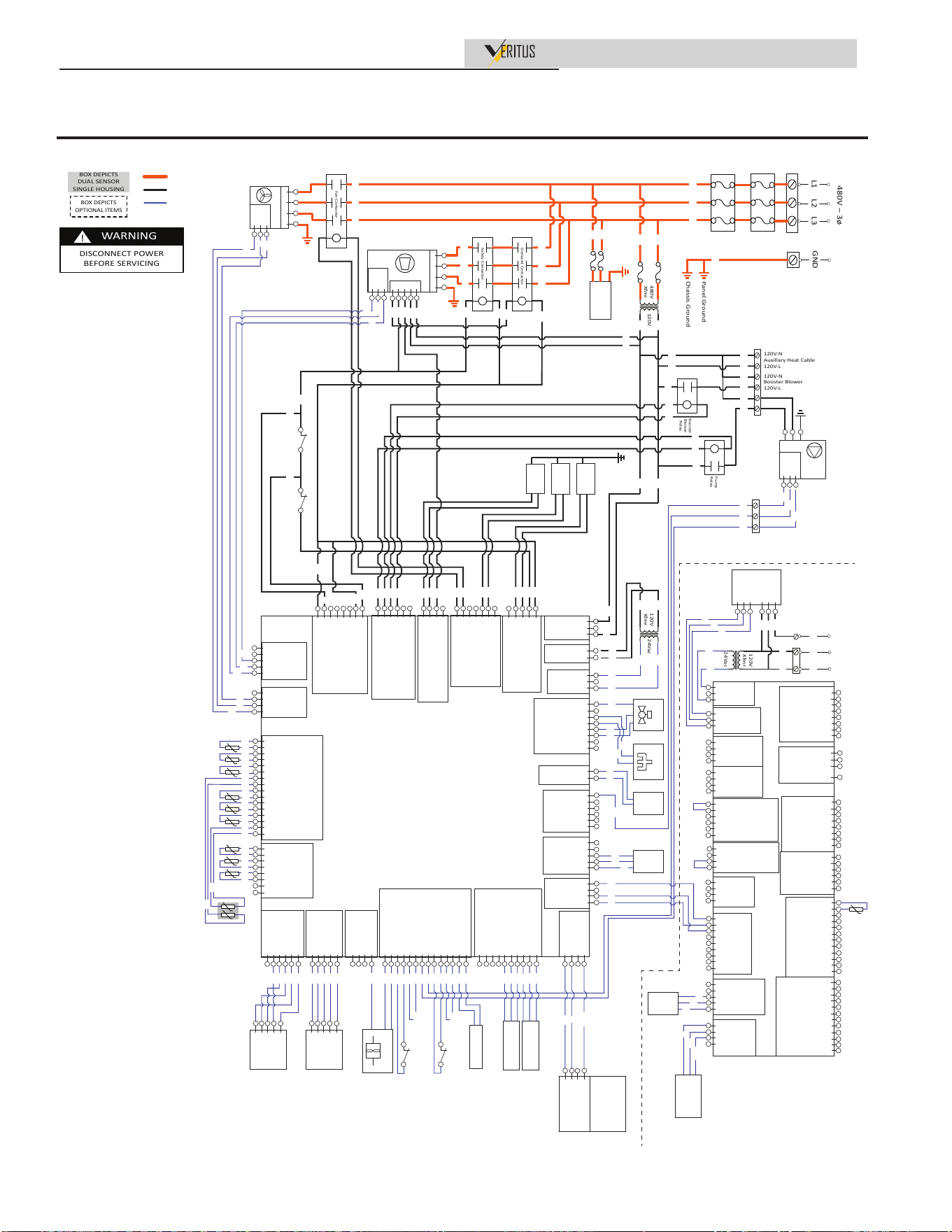
Installation & Operation Manual
12 Diagrams
Figure 12-4 Wiring Diagram - AHP060-480 & AHP140-480
On/Off
Switch
480V
Xfmr
120V
Demand Contactor
Fan Contactor
Safety Contactor
480V – 3ø
L1
L2
L3
GND
L1 L2 L3 G
L1
L2
D
M1
M2
RS485 +
GND
RS485 -
Compressor
L1 L2 L3 G
RS485 B
RS485 A
GND
Fan
R BL BK
R BL BK
R BL BK
Crankcase
Heater
Booster
Blower
Relay
R
BK
120V
Xfmr
24Vac
BK
R
BK
W
BK
W
PWM Out
PWM Ref
PWM In
Pump
G
N
L
BK W
BL
W W W BK BL
PR
PR
Panel Ground
Chassis Ground
GN
BK W
BK
W
120V-N
Booster Blower
120V-L
120V-N
Auxillary Heat Cable
120V-L
W
Y BL
Pump
Relay
BL
W
PR
W
BL
W PR
W
Drain Pan
Heat Trace
Condenser
Heat Trace
Water Inlet
Heat Trace
High
Pressure
Switch
High Water
Temperature
Switch
BR
Y
PK
BL
Y
J16-5 120V-N Compressor Relay
J16-4 120V-L Compressor Relay
J16-3 120V-N Water Inlet HT
J16-2 120V-L Water Inlet HT
J16-1 ----
J29-7 ----
J29-6 120V-N Condenser HT
J29-5 120V-L Condenser HT
J29-4 ----
J29-3 ----
J29-2 120V-N Fan Contactor
J29-1 120V-L Fan Contactor
J15-4 ----
J15-3 120V-L Compressor Demand
J15-2 120V-N Drain Pan HT
J15-1 120V-L Drain Pan HT
J28-6 ----
J28-5 ----
J28-4 120V-N Booster Blower Relay
J28-3 120V-L Booster Blower Relay
J28-2 120V-N Pump Relay
J28-1 120V-L Pump Relay
120VAC-N J20-1
---- J20-2
120VAC-L J20-3
24VAC-L J14-1
24VAC-L J14-2
DGND J14-3
24VAC-L 4Way J14-4
Valve Open J14-5
Valve Close J14-6
---- J14-7
---- J14-8
24VAC-L J19-1
---- J19-2
24VAC-N J19-3
24VAC-N Light J1-1
24VAC-L Light J1-2
J8-1 ----
J8-2 ----
J8-3 RS485-A
J8-4 RS485-B
J8-5 DGND
Compressor
---- J17-1
---- J17-2
RS485-A J17-3
RS485-B J17-4
DGND J17-5
NFC Key
DGND J27-1
---- J27-2
RS485-A J27-3
RS485-B J27-4
IN
DGND J7-1
---- J7-2
RS485-A J7-3
RS485-B J7-4
OUT
Disch P Trans 0-10V J6-1
DGND J6-2
Disch P Trans +12V J6-3
DGND J6-4
Suc P Trans 0-10V J6-5
Suc P Trans +12V J6-6
---- J6-7
---- J6-8
---- J6-9
---- J6-10
0-10V Input
DGND J2-1
Reset J2-8
DGND J2-2
Compressor FB J2-9
DGND J2-3
Blocked Drain SW J2-10
DGND J2-4
PWM Input J2-11
DGND J2-5
Safety FB J2-12
DGND J2-6
Low Pressure Switch J2-13
DGND J2-7
Pulse Count J2-14
Digital Input
+12V J13-1
EEV_4 J13-2
EEV_3 J13-3
EEV_2 J13-4
EEV_1 J13-5
EEV One
+12V J26-1
EEV_1 J26-2
EEV_2 J26-3
EEV_3 J26-4
EEV_4 J26-5
---- J26-6
EEV Two
PWM Out J10-1
---- J10-2
---- J10-3
---- J10-4
---- J10-5
---- J10-6
0-10V Output
+12V J23-1
---- J23-2
---- J23-3
---- J23-4
0-10V Input
J4-1 Evap 1B
J4-2 Evap 1B
J4-3 Evap 2B
J4-4 Evap 2B
J4-5 Evap 2A
J4-6 Evap 2A
J4-7 ----
J4-8 ----
Temperature Input
J3-1 Discharge
J3-9 Discharge
J3-2 Inlet Water
J3-10 Inlet Water
J3-3 Suction
J3-11 Suction
J3-4 Outlet Water A
J3-12 Outlet Water A
J3-5 Ambient
J3-13 Ambient
J3-6 Liquid Line
J3-14 Liquid Line
J3-7 Evap 1A
J3-15 Evap 1A
J3-8 Outlet Water B
J3-16 Outlet Water B
Temperature Input
J9-1 ----
J9-2 RS485-A
J9-3 RS485-B
J9-4 DGND
Fan
J5-8 High Pressure Switch_0
J5-7 High Pressure Switch_1
J5-6 ----
J5-5 ----
J5-4 ----
J5-3 ----
J5-2 High Water Temp Switch_0
J5-1 High Water Temp Switch_1
HPC
(Heat Pump Controller)
120VAC-L J25-1
120VAC-N J25-2
R GN O BL
BL
BK
BR Y
GY
PK BK
Ball Valve
W
O Y
4 Way Valve
W
PR
W
BK
GY
O
GY
BR
W
R
BR
GY
Y
PR
W
W
R
Status
Light
BOX DEPICTS
OPTIONAL ITEMS
BOX DEPICTS
DUAL SENSOR
SINGLE HOUSING
WARNING
DISCONNECT POWER
BEFORE SERVICING
!
480 VAC
120 VAC
Low Voltage
NOTES:
1. All wiring must be installed in accordance with: local, state, provincial and national code requirements per either N.E.C. in USA or C.S.A. in Canada.
2. If any original equipment wire as supplied with the appliance must be replaced, it must be replaced with wire having the same wire gauge (AWG) and rated for a minimum of 105°C.
Exceptions: Replacement shielded cables must be purchased from the factory. Use of a non-approved wire or cable can lead to operational problems which could result in non-repairable
damage to the integrated controller or other components.
3. Actual connector block locations may vary from those shown on diagrams. Refer to actual components for proper connector block locations when using diagrams to troubleshoot unit.
W BL
NFC
Key
R BK
Bare
BR
BR
BR
1
2
3
4
5
EEV Front
(oblique)
1
2
3
4
5
EEV Rear
(vertical)
GY
BK
Y
R
O
GY
O
R
Y
BK
Flow Sensor
W
PK
BR
Low Pressure Switch
Safety Contactor N.O. Feedback
Blocked Drain Switch
Demand Contactor N.O. Feedback
Reset Button
Suction Pressure
Transducer
Discharge Pressure
Transducer
BK
BL
BL BK
BL
BK
Unit terminal box
BK
GN
R
GN
GN
PR
GN
BR
GY
Y
R BK
Bare
R
BK
Bare
R
Y
PR
Y
O
PR
J27-1 DGND
J27-2 ----
J27-3 RS485-A
J27-4 RS485-B
IN
Heat Pump
downstream
Cascade
(HPC)
HMI
Display
Bare
R
BK
Dual Outlet
Water Sensor
BMS 0-10V- J18-1
BMS 0-10V+ J18-2
---- J18-3
-------
---- J18-8
Analog In
---- J10-1
---- J10-2
Backup 1 J10-3
DGND J10-4
Backup 2 J10-5
DGND J10-6
Rate Output J10-7
DGND J10-8
Analog Out 0-10V
J1-1 EcoPort-A
J1-2 EcoPort-B
J1-3 DGND
EcoPort
J8A RCAD-A
J8B RCAD-B
J8C DGND
J8D ----
RCAD (HMI)
J7-1 +5V
J7-2 PC-A
J7-3 PC-B
J7-4 DGND
PC
J26A +5V
J26B ----
J26C Cascade-A
J26D Cascade-B
J26E DGND
NFC Key
J11-1 GND
J11-2 B
J11-3 A
J11-4 GND
J11-5 B
J11-6 A
J11-7 GND
J11-8 B
J11-9 A
Cascade RS485
J2-1 T-stat/Enable GND
J2-2 T-stat/Enable IN
J2-3 ----
J2-4 ----
J2-5 BMS Enable GND
J2-6 BMS Enable IN
Digital IN
J19-1 24VAC-L
J19-2 ----
J19-3 24VAC-N
J14-1 14VAC-N
J14-2 SW1 24VAC-L
J14-3 24VAC-N
J14-4 SW2 24VAC-L
J4-1 SW4 24VAC-L
J4-2 24VAC-N
J4-3 SW3 24VAC-L
J4-4 24VAC-N
Pump Relays
J22-1 ----
J22-2 ----
J22-3 Louver Prove GND
J22-4 Louver Proving
Digital IN
Backup Heat 1 J13-1
Backup 1 SW J13-2
Backup Heat 2 J13-3
Backup 2 SW J13-4
Alarm J13-5
Alarm SW J13-6
Runtime J13-7
Runtime SW J13-8
Mix V Open SW J5-1
Mix V Open J5-2
Mix V Close SW J5-3
Mix V Close J5-4
Louver Relay SW J5-5
Louver Relay J5-6
Tank 1 Ret J3-1
Tank 1 Temp J3-2
Tank 2 Ret J3-3
Tank 2 Temp J3-4
Tank 3 Ret J3-5
Tank 3 Temp J3-6
Tank 4 Ret J3-7
Tank 4 Temp J3-8
Tank 5 Ret J3-9
Tank 5 Temp J3-10
Tank 6 Ret J3-11
Tank 6 Temp J3-12
---- J20-1
---- J20-2
---- J20-3
---- J20-4
Outdoor Temp J20-5
Outdoor Ret J20-6
Recirc Return J20-7
Recirc Return Ret J20-8
System Return J20-9
Sys Return Ret J20-10
System Supply J20-11
Sys Supply Ret J20-12
Relays Out
Temp
Sensors
SCB
(System Control)
120V
Xfmr
24Vac
LN
120Vac
GND
Display
Panel
Enclosure
BL
Y
R BK
Bare
NFC
Key
R
BK
Bare
R
BK
Bare
R
BL
BK
R
BK
Bare
R
BK
Bare
Unit rear panel
BK
BK W
BK
W
100370015 REV C
R
BL
BL
PRR
BK
BK
PK
W
W
GND 10
120V-L 12
120V-N 5
RS485(-) 1
RS485(+) 7
DGND 8
CTA-2045
BKW
BK
W
GN
R
BK
GN
480V
Xfmr
120V
Demand Contactor
Fan Contactor
Safety Contactor
480V – 3ø
L1
L2
L3
GND
L1 L2 L3 G
L1
L2
D
M1
M2
RS485 +
GND
RS485 -
Compressor
L1 L2 L3 G
RS485 B
RS485 A
GND
Fan
BR* O* Y*
BR O Y
BR O Y
Crankcase
Heater
Booster
Blower
Relay
BR
Y
120V
Xfmr
24Vac
Y
BR
BK
W
BK
W
PWM Out
PWM Ref
PWM In
Pump
G
N
L
BK W
BL
W W W BK BL
PR
PR
Panel Ground
Chassis Ground
GN
BK W
BK
W
120V-N
Booster Blower
120V-L
120V-N
Auxillary Heat Cable
120V-L
W
Y BL
Pump
Relay
BL
W
PR
W
BL
W PR
W
Drain Pan
Heat Trace
Condenser
Heat Trace
Water Inlet
Heat Trace
High
Pressure
Switch
High Water
Temperature
Switch
BR
Y
PK
BL
Y
J16-5 120V-N Compressor Relay
J16-4 120V-L Compressor Relay
J16-3 120V-N Water Inlet HT
J16-2 120V-L Water Inlet HT
J16-1 ----
J29-7 ----
J29-6 120V-N Condenser HT
J29-5 120V-L Condenser HT
J29-4 ----
J29-3 ----
J29-2 120V-N Fan Contactor
J29-1 120V-L Fan Contactor
J15-4 ----
J15-3 120V-L Compressor Demand
J15-2 120V-N Drain Pan HT
J15-1 120V-L Drain Pan HT
J28-6 ----
J28-5 ----
J28-4 120V-N Booster Blower Relay
J28-3 120V-L Booster Blower Relay
J28-2 120V-N Pump Relay
J28-1 120V-L Pump Relay
120VAC-N J20-1
---- J20-2
120VAC-L J20-3
24VAC-L J14-1
24VAC-L J14-2
DGND J14-3
24VAC-L 4Way J14-4
Valve Open J14-5
Valve Close J14-6
---- J14-7
---- J14-8
24VAC-L J19-1
---- J19-2
24VAC-N J19-3
24VAC-N Light J1-1
24VAC-L Light J1-2
J8-1 ----
J8-2 ----
J8-3 RS485-A
J8-4 RS485-B
J8-5 DGND
Compressor
---- J17-1
---- J17-2
RS485-A J17-3
RS485-B J17-4
DGND J17-5
NFC Key
DGND J27-1
---- J27-2
RS485-A J27-3
RS485-B J27-4
IN
DGND J7-1
---- J7-2
RS485-A J7-3
RS485-B J7-4
OUT
Disch P Trans 0-10V J6-1
DGND J6-2
Disch P Trans +12V J6-3
DGND J6-4
Suc P Trans 0-10V J6-5
Suc P Trans +12V J6-6
---- J6-7
---- J6-8
---- J6-9
---- J6-10
0-10V Input
DGND J2-1
Reset J2-8
DGND J2-2
Compressor FB J2-9
DGND J2-3
Blocked Drain SW J2-10
DGND J2-4
PWM Input J2-11
DGND J2-5
Safety FB J2-12
DGND J2-6
Low Pressure Switch J2-13
DGND J2-7
Pulse Count J2-14
Digital Input
+12V J13-1
EEV_4 J13-2
EEV_3 J13-3
EEV_2 J13-4
EEV_1 J13-5
EEV One
+12V J26-1
EEV_1 J26-2
EEV_2 J26-3
EEV_3 J26-4
EEV_4 J26-5
---- J26-6
EEV Two
PWM Out J10-1
---- J10-2
---- J10-3
---- J10-4
---- J10-5
---- J10-6
0-10V Output
+12V J23-1
---- J23-2
---- J23-3
---- J23-4
0-10V Input
J4-1 Evap 1B
J4-2 Evap 1B
J4-3 Evap 2B
J4-4 Evap 2B
J4-5 Evap 2A
J4-6 Evap 2A
J4-7 ----
J4-8 ----
Temperature Input
J3-1 Discharge
J3-9 Discharge
J3-2 Inlet Water
J3-10 Inlet Water
J3-3 Suction
J3-11 Suction
J3-4 Outlet Water A
J3-12 Outlet Water A
J3-5 Ambient
J3-13 Ambient
J3-6 Liquid Line
J3-14 Liquid Line
J3-7 Evap 1A
J3-15 Evap 1A
J3-8 Outlet Water B
J3-16 Outlet Water B
Temperature Input
J9-1 ----
J9-2 RS485-A
J9-3 RS485-B
J9-4 DGND
Fan
J5-8 High Pressure Switch_0
J5-7 High Pressure Switch_1
J5-6 ----
J5-5 ----
J5-4 ----
J5-3 ----
J5-2 High Water Temp Switch_0
J5-1 High Water Temp Switch_1
HPC
(Heat Pump Controller)
120VAC-L J25-1
120VAC-N J25-2
R GN O BL
BL
BK
BR Y
GY
PK BK
Ball Valve
W
O Y
4 Way Valve
W
PR
W
BK
GY
O
GY
BR
W
R
BR
GY
Y
PR
W
W
R
Status
Light
BOX DEPICTS
OPTIONAL ITEMS
BOX DEPICTS
DUAL SENSOR
SINGLE HOUSING
WARNING
DISCONNECT POWER
BEFORE SERVICING
!
480 VAC
120 VAC
Low Voltage
NOTES:
1. All wiring must be installed in accordance with: local, state, provincial and national code requirements per either N.E.C. in USA or C.S.A. in Canada.
2. If any original equipment wire as supplied with the appliance must be replaced, it must be replaced with wire having the same wire gauge (AWG) and rated for a minimum of 105°C.
Exceptions: Replacement shielded cables must be purchased from the factory. Use of a non-approved wire or cable can lead to operational problems which could result in non-repairable
damage to the integrated controller or other components.
3. Actual connector block locations may vary from those shown on diagrams. Refer to actual components for proper connector block locations when using diagrams to troubleshoot unit.
W BL
NFC
Key
R BK
Bare
BR
BR
BR
1
2
3
4
5
EEV Front
(oblique)
1
2
3
4
5
EEV Rear
(vertical)
GY
BK
Y
R
O
GY
O
R
Y
BK
Flow Sensor
W
PK
BR
Low Pressure Switch
Safety Contactor N.O. Feedback
Blocked Drain Switch
Demand Contactor N.O. Feedback
Reset Button
Suction Pressure
Transducer
Discharge Pressure
Transducer
BK
BL
BL BK
BL
BK
Unit terminal box
BK
GN
R
GN
GN
PR
GN
BR
GY
Y
R BK
Bare
R
BK
Bare
R
Y
PR
Y
O
PR
J27-1 DGND
J27-2 ----
J27-3 RS485-A
J27-4 RS485-B
IN
Heat Pump
downstream
Cascade
(HPC)
HMI
Display
Bare
R
BK
Dual Outlet
Water Sensor
BMS 0-10V- J18-1
BMS 0-10V+ J18-2
---- J18-3
-------
---- J18-8
Analog In
---- J10-1
---- J10-2
Backup 1 J10-3
DGND J10-4
Backup 2 J10-5
DGND J10-6
Rate Output J10-7
DGND J10-8
Analog Out 0-10V
J1-1 EcoPort-A
J1-2 EcoPort-B
J1-3 DGND
EcoPort
J8A RCAD-A
J8B RCAD-B
J8C DGND
J8D ----
RCAD (HMI)
J7-1 +5V
J7-2 PC-A
J7-3 PC-B
J7-4 DGND
PC
J26A +5V
J26B ----
J26C Cascade-A
J26D Cascade-B
J26E DGND
NFC Key
J11-1 GND
J11-2 B
J11-3 A
J11-4 GND
J11-5 B
J11-6 A
J11-7 GND
J11-8 B
J11-9 A
Cascade RS485
J2-1 T-stat/Enable GND
J2-2 T-stat/Enable IN
J2-3 ----
J2-4 ----
J2-5 BMS Enable GND
J2-6 BMS Enable IN
Digital IN
J19-1 24VAC-L
J19-2 ----
J19-3 24VAC-N
J14-1 14VAC-N
J14-2 SW1 24VAC-L
J14-3 24VAC-N
J14-4 SW2 24VAC-L
J4-1 SW4 24VAC-L
J4-2 24VAC-N
J4-3 SW3 24VAC-L
J4-4 24VAC-N
Pump Relays
J22-1 ----
J22-2 ----
J22-3 Louver Prove GND
J22-4 Louver Proving
Digital IN
Backup Heat 1 J13-1
Backup 1 SW J13-2
Backup Heat 2 J13-3
Backup 2 SW J13-4
Alarm J13-5
Alarm SW J13-6
Runtime J13-7
Runtime SW J13-8
Mix V Open SW J5-1
Mix V Open J5-2
Mix V Close SW J5-3
Mix V Close J5-4
Louver Relay SW J5-5
Louver Relay J5-6
Tank 1 Ret J3-1
Tank 1 Temp J3-2
Tank 2 Ret J3-3
Tank 2 Temp J3-4
Tank 3 Ret J3-5
Tank 3 Temp J3-6
Tank 4 Ret J3-7
Tank 4 Temp J3-8
Tank 5 Ret J3-9
Tank 5 Temp J3-10
Tank 6 Ret J3-11
Tank 6 Temp J3-12
---- J20-1
---- J20-2
---- J20-3
---- J20-4
Outdoor Temp J20-5
Outdoor Ret J20-6
Recirc Return J20-7
Recirc Return Ret J20-8
System Return J20-9
Sys Return Ret J20-10
System Supply J20-11
Sys Supply Ret J20-12
Relays Out
Temp
Sensors
SCB
(System Control)
120V
Xfmr
24Vac
LN
120Vac
GND
Display
Panel
Enclosure
BL
Y
R BK
Bare
NFC
Key
R
BK
Bare
R
BK
Bare
BR
O
Y
R
BK
Bare
R
BK
Bare
Unit rear panel
BK
BK W
BK
W
100370015 REV E
R
BL
BL
PRR
BK
BK
PK
W
W
GND 10
120V-L 12
120V-N 5
RS485(-) 1
RS485(+) 7
DGND 8
CTA-2045
BKW
BK
W
GN
R
BK
GN
*Some models may use red, blue, and black colored wires for all 480V power,
rather than brown, orange, and yellow as noted below.
3000062132
100370015 REV E
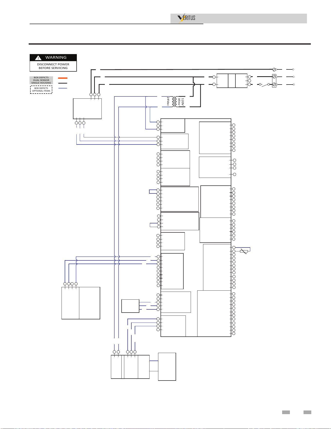
12 Diagrams
Figure 12-5 Display Panel Wiring Diagram
BOX DEPICTS
OPTIONAL ITEMS
BOX DEPICTS
DUAL SENSOR
SINGLE HOUSING
WARNING
DISCONNECT POWER
BEFORE SERVICING
!
480 VAC
120 VAC
Low Voltage
NOTES:
1. All wiring must be installed in accordance with: local, state, provincial and national code requirements per either N.E.C. in USA or C.S.A. in Canada.
2. If any original equipment wire as supplied with the appliance must be replaced, it must be replaced with wire having the same wire gauge (AWG) and rated for a minimum of 105°C.
Exceptions: Replacement shielded cables must be purchased from the factory. Use of a non-approved wire or cable can lead to operational problems which could result in non-repairable
damage to the integrated controller or other components.
3. Actual connector block locations may vary from those shown on diagrams. Refer to actual components for proper connector block locations when using diagrams to troubleshoot unit.
BMS 0-10V- J18-1
BMS 0-10V+ J18-2
---- J18-3
-------
---- J18-8
Analog In
---- J10-1
---- J10-2
Backup 1 J10-3
DGND J10-4
Backup 2 J10-5
DGND J10-6
Rate Output J10-7
DGND J10-8
Analog Out 0-10V
J1-1 EcoPort-A
J1-2 EcoPort-B
J1-3 DGND
EcoPort
J8A RCAD-A
J8B RCAD-B
J8C DGND
J8D ----
RCAD (HMI)
J7-1 +5V
J7-2 PC-A
J7-3 PC-B
J7-4 DGND
PC
J26A +5V
J26B ----
J26C Cascade-A
J26D Cascade-B
J26E DGND
NFC Key
J11-1 GND
J11-2 B
J11-3 A
J11-4 GND
J11-5 B
J11-6 A
J11-7 GND
J11-8 B
J11-9 A
Cascade RS485
J2-1 T-stat/Enable GND
J2-2 T-stat/Enable IN
J2-3 ----
J2-4 ----
J2-5 BMS Enable GND
J2-6 BMS Enable IN
Digital IN
J19-1 24VAC-L
J19-2 ----
J19-3 24VAC-N
J14-1 14VAC-N
J14-2 SW1 24VAC-L
J14-3 24VAC-N
J14-4 SW2 24VAC-L
J4-1 SW4 24VAC-L
J4-2 24VAC-N
J4-3 SW3 24VAC-L
J4-4 24VAC-N
Pump Relays
J22-1 ----
J22-2 ----
J22-3 Louver Prove GND
J22-4 Louver Proving
Digital IN
Backup Heat 1 J13-1
Backup 1 SW J13-2
Backup Heat 2 J13-3
Backup 2 SW J13-4
Alarm J13-5
Alarm SW J13-6
Runtime J13-7
Runtime SW J13-8
Mix V Open SW J5-1
Mix V Open J5-2
Mix V Close SW J5-3
Mix V Close J5-4
Louver Relay SW J5-5
Louver Relay J5-6
Tank 1 Ret J3-1
Tank 1 Temp J3-2
Tank 2 Ret J3-3
Tank 2 Temp J3-4
Tank 3 Ret J3-5
Tank 3 Temp J3-6
Tank 4 Ret J3-7
Tank 4 Temp J3-8
Tank 5 Ret J3-9
Tank 5 Temp J3-10
Tank 6 Ret J3-11
Tank 6 Temp J3-12
---- J20-1
---- J20-2
---- J20-3
---- J20-4
Outdoor Temp J20-5
Outdoor Ret J20-6
Recirc Return J20-7
Recirc Return Ret J20-8
System Return J20-9
Sys Return Ret J20-10
System Supply J20-11
Sys Supply Ret J20-12
Relays Out
Temp
Sensors
SCB
(System Control)
120V
Xfmr
24Vac
LN
120Vac
GND
BL
Y
NFC
Key
R
BK
Bare
R
BK
Bare
12 120V-L
5 120V-N
10 GND
RS485(-) 1
RS485(+) 7
DGND 8
CTA-2045
BKW
BK
W
J27-1 DGND
J27-2 ----
J27-3 RS485-A
J27-4 RS485-B
IN
Heat Pump
downstream
Cascade
(HPC)
GN
BK
R
GN
J12-3 DGND
J12-2 RS485-B
J12-1 RS485-A
DISPLAY
CONTROL
J2-2 24VAC-L
J2-1 24VAC-N
BL
Y
HMI
J25-2
J25-1
Voltage
Board
J23-1
J23-2
J23-3
BK
BKW
W
R
BK
Bare
73
Installation & Operation Manual

NOTES
Installation & Operation Manual
74

NOTES
Installation & Operation Manual
75

Revision Notes: Revision A (PCP #3000056598/ CN #500042943)
initial release.
Revision B (PCP #3000057735/ CN #500043946) reflects updates
throughout.
Revision C (PCP #3000058985 / CN #500045045) relfects updates
throughout prior to release.
Revision D (PCP #3000059127 / CN #500045231) reflects update
throughout as well as updated ladder diagrams.
Revision E (PCP #3000060652 / CN #500046800) reflects updated
diagrams, additional tables, and information throughout.
Revision F (PCP #3000060820 / CN #500046810) reflects the addition
of a dielectric notice to page 25.
Revision G (PCP #3000061798 / CN #500048216) reflects updated
diagrams and images throughout.
Revision H (PCP #3000063502 / CN #500049263) reflects updates to
the table on page 15 and figure 2-8.
Revision J (PCP #3000066529 / CN #500052248) reflects the addition
of 208V.
Revision K (PCP #3000070081 / CN #500055670) reflects updates to
the product summary table and page references.
Revision L (PCP #3000070438 / CN #500055910) reflects updates to
Line Voltage Connections on page 43.
100371005_2000627791_Rev L
02/26