MANUAL 10105-SB REV 0 (04/21)
$21.00
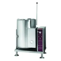
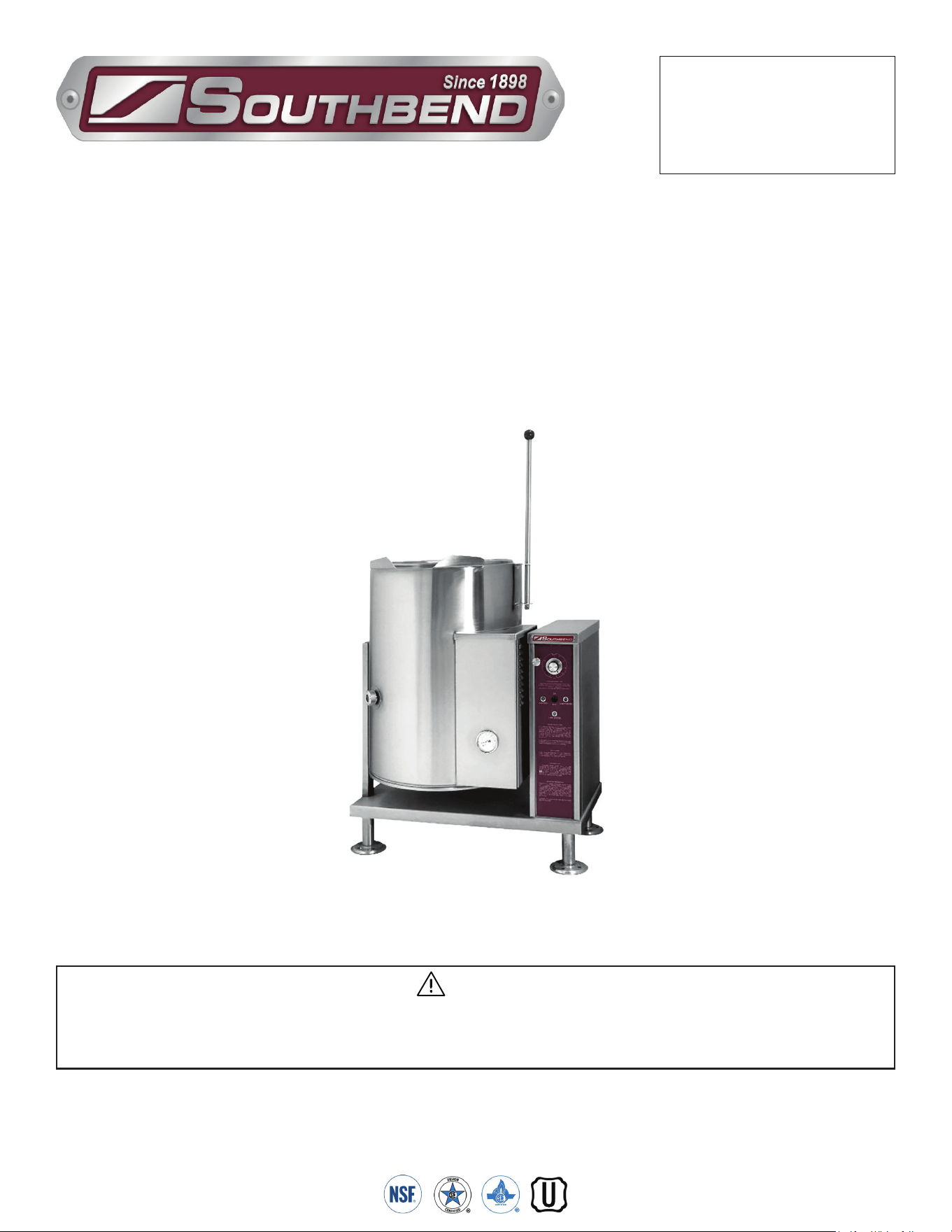
Gas Fired Steam Jacketed Tilting Kettle
MANUAL SECTION CO
IMPORTANT FOR FUTURE REFERENCE
Please complete this information and retain this
manual for the life of the equipment:
Model #:
___________________________
Serial #:
___________________________
Date Purchased:
_____________________
WARNING
Improper installation, adjustment, alteration, service or maintenance can cause property damage, injury
or death. Read the installation, operating and maintenance instructions thoroughly before installing or
servicing this equipment.
Gas Fired Steam Jacketed Tilting Kettle
KGCT-12
Installation & Operation Manual
Model KGCT-12
SOUTHBEND STEAM
1100 Old Honeycutt Road Fuquay-Varina, North Carolina 27526 USA
www.southbendnc.com
INSTALLATION & OPERATION MANUAL 10105-SB REV 0 (04/21)
PAGE
2
OF 28
Gas Fired Steam Jacketed Tilting Kettle
SAFETY PRECAUTIONS
Before installing and operating this equipment, be sure everyone involved in its operation is fully trained and aware of
precautions. Accidents and problems can be caused by failure to follow fundamental rules and precautions.
The following symbols, found throughout this manual, alert you to potentially dangerous conditions to the operator,
service personnel, or to the equipment.
CAUTION
WARNING
NOTICE
This symbol warns of immediate hazards that will result in severe injury or death.
This symbol refers to a potential hazard or unsafe practice that could result in injury or death.
This symbol refers to a potential hazard or unsafe practice that could result in injury, product
damage, or property damage.
This symbol refers to information that needs special attention or must be fully
understood, even though not dangerous.
DANGER
WARNING
Improper installation, operation, adjustment, alteration, service or maintenance can cause property damage, injury
or death. Read the installation, operating and maintenance instructions thoroughly before installing, operating or
servicing this equipment.
NOTICE
This manual should be retained for future reference.
NOTICE
This product is intended for commercial use only. NOT FOR HOUSEHOLD USE.
Copyright © 2021 by Southbend Steam. All rights reserved. Published in the United States of America.
Specifications
IMPORTANT NOTES FOR INSTALLATION AND OPERATION
WARNING
This is the safety alert symbol. It is used to alert you to potential personal injury hazards. Obey all safety messages
that follow this symbol to avoid possible injury or death.
WARNING
FOR YOUR SAFETY:
Do not store or use gasoline or other ammable vapors or liquids in the vicinity of this or any other appliance.
PURCHASER: Instructions to be followed in the event the operator of this appliance smells gas must be posted
in a prominent location. This information shall be obtained by consulting the local gas supplier.
Do not attempt to operate this unit in the event of a power failure.
Keep the appliance area free and clear from combustibles.
DO NOT obstruct the ow of combustion and ventilation air.
Adequate clearances MUST be maintained for servicing and proper operation.
Contact the factory, the factory representative or a local service company to perform maintenance and repairs
should the appliance malfunction. Refer to warranty terms.

INSTALLATION & OPERATION MANUAL 10105-SB REV 0 (04/21)
PAGE
3
OF28
Gas Fired Steam Jacketed Tilting Kettle
RETAIN THIS MANUAL FOR FUTURE REFERENCE.
Table of Contents
Important Notes For Installation and Operation .................................................................... 2
Service Connections ............................................................................................................. 4
Introduction ........................................................................................................................... 5
Installation ............................................................................................................................. 6
Operation .............................................................................................................................. 8
Cleaning ................................................................................................................................ 10
Periodic Maintenance ........................................................................................................... 12
Service .................................................................................................................................. 13
Troubleshooting .................................................................................................................... 15
Appendix A, Material Safety Data Sheet ............................................................................... 16
Table of Contents
INSTALLATION & OPERATION MANUAL 10105-SB REV 0 (04/21)
PAGE
4
OF 28
Gas Fired Steam Jacketed Tilting Kettle
Service Connections
Service Connections
GAS CHARACTERISTICS
* For use on non-combustible floors only.
As continued product improvement is a policy of Southbend Steam, specications are subject to changge without notice.
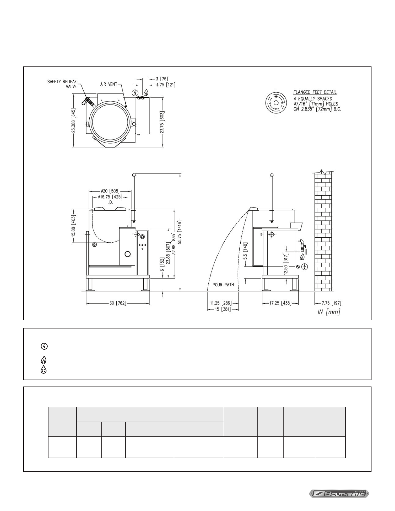
SERVICE CONNECTIONS
– Electrical Connection - Unless otherwise specied, eld wire electrical connection to be 120V, 60 Hz, 1 Phase with grounding wire.
Unit Furnished with 8’ cord and 3-prong plug. Total max AMPS 2.0
– Gas Connection - 3/4” pipe supply line required
– Cold Water - 3/8” O.D. tubing to faucet (OPTIONAL)
Model
Gas Supply
Capacity
Shipping
Weight
Minimum Clearance
BTU/HR. kW/HR. Supply Pipe Pressure (W.C.)
KGCT-12 43,000 12.6
Natural
6”-14” (152-356 mm)
Propane
11”-14” (279-356 mm)
12 Gallon
46 Liter
255 lbs.
[116 kg.]
SIDES
BACK
0
6 [152

INSTALLATION & OPERATION MANUAL 10105-SB REV 0 (04/21)
PAGE
5
OF28
Gas Fired Steam Jacketed Tilting Kettle Introduction
Introduction
Description
Model KGCT-12 (12 gallon capacity) gas red, self-contained, tilting kettle. The kettle has a jacket of double-wall
construction forming a sealed reservoir around the lower two-thirds of the kettle. The reservoir is charged with distilled
water. The kettle is equipped with a “clean lock” to hold kettle in cooking position or tilted 105 degrees for ease of
cleaning. The kettle is also equipped with automatic ignition, low water cut o and tilt switch, which, when activated,
shuts down the burner.
Basic Function
The kettle operates by generating steam in the kettle reservoir. The sequence of operation is as follows:
1. Operator turns the power switch to the on position and sets the temperature control dial to the desired setting.
2. The red light comes on indicating the kettle is heating. The green “IGNITION” light comes on indicating that the
ignition and burner are active.
3. Once the kettle reaches the set temperature, the red “TEMPERATURE” light and the green “IGNITION” light
extinguish.
4. All kettles are supplied with sucient water in the jacket. If for any reason the water level falls below the required
amount to operate the kettle, the burner shuts down and the amber light comes on. See Adding Water in Service
section.
5. The sight glass indicates the water level within the kettle jacket.
6. The relief valve is a safety feature which prevents the internal kettle pressure from exceeding 50 PSI. It should never
be tampered with.
INSTALLATION & OPERATION MANUAL 10105-SB REV 0 (04/21)
PAGE
6
OF 28
Gas Fired Steam Jacketed Tilting Kettle
UNPACKING
IMMEDIATELY INSPECT FOR SHIPPING DAMAGE
Immediately after unpacking the steamer, check for possible shipping damage. If the steamer is found to be damaged,
save the packaging material and contact the carrier within 15 days of delivery.
Prior to installation, verify that the type of gas supply (natural or propane) and electrical service agree with the
specications on the rating plate located on the left side panel as you face the front of the braising pan. If the supply
and equipment requirements do not agree, contact your dealer immediately.
Installation
INSTALLATION
Installation Codes and Standards
Installation must conform with local codes, or in the absence of local codes, with the National Fuel Gas Code,
ANSI Z223.1/NFPA 54, or the Natural Gas and Propane Installation Code, CSA B149.1, as applicable.
1. The appliance and its individual shut off valve must be disconnected from the gas supply piping system during
any pressure testing of that system at pressures in excess of 1/2 psi (3.5 kPa).
2. The appliance must be isolated from the gas supply piping system by closing its individual manual shut off
valve during any pressure testing of the gas supply piping system at test pressures equal to or less than
1/2 psi (3.5 kPa).
Electrical grounding must be provided in accordance with local codes, or in the absence of local codes, with the
National Electrical Code, ANSI/NFPA 70, or the Canadian Electrical Code, CSA C22.2, as applicable.
Ventilation must be provided in accordance with local codes, or in the absence of local codes, with ANSI/NFPA 96
Standard for Ventilation and Fire Protection of Commercial Cooking Operations.
The electrical diagram is located on the inside of side panel of left hand console.
WARNING
ELECTRICAL GROUNDING INSTRUCTIONS
This appliance is equipped with a three-prong (grounding) plug for your protection against shock hazard
and should be plugged directly into a properly grounded three-prong receptacle. Do not cut or remove the
grounding prong from this plug. (120V units only).
INSTALLATION & OPERATION MANUAL 10105-SB REV 0 (04/21)
PAGE
7
OF28
Gas Fired Steam Jacketed Tilting Kettle INSTALLATION
WARNING
Do not connect the appliance to the electrical supply until after the gas connection has been made.
Gas Connection
1. The Serial and Rating Plate on the unit indicates the type of gas your unit is equipped to burn. DO NOT connect to
any other gas type.
2. A 3/4” NPT line is provided at rear for the connection. The unit is equipped with an internal pressure regulator which is
set at 4” W.C. manifold pressure for Natural Gas and 10” W.C. for Propane Gas. Use 1/8” pipe tap on the union elbow
assembly located in the console for checking pressure.
An adequate gas supply is imperative. Undersized or low pressure lines will restrict the volume of gas required for
satisfactory performance. A steady supply pressure, minimum 6 inch W.C. for natural gas and minimum 12 inch W.C.
for propane gas is recommended. With all units operating simultaneously, the manifold pressure on all units should
not show any appreciable drop. Fluctuations of more than 25% on natural gas and 10% on propane gas will create
problems, aecting burner operation. Contact you gas company for correct supply line sizes.
Purge the supply line to clean out any dust, dirt or other foreign matter before connecting the line to the unit. Use pipe joint
compound which is suitable for use with L.P. on all threaded connections.
Test pipe connections thoroughly for gas leaks.
NOTICE
If this equipment is being installed at over 2,000 feet altitude and was not so specied on order, contact service
department. Failure to install with proper orice sizing may void the warranty.
CAUTION
The pipe thread compound used when installing pipes must be a type that is resistant
to the action of liquied petroleum or propane gases.
WARNING
Never use an open ame to check for gas leaks. Check all connections for leaks using soapy water before use.
To Install
1. Uncrate carefully. Report any hidden freight damage to the freight company immediately.
2. Ideally an exhaust system should be directly above the appliance to exhaust combustion gases generated by the unit.
3. The appliance is intended for use on noncombustible oors. The minimum clearance from combustible and
noncombustible oor construction is 0” on right side, 0” on left side and 6” (152 mm) from the back of the ue chimney.
4. Appliance location must allow air supply to unit and obstruction free clearance for air opening into the combustion chamber.
5. Set the appliance in place and level using spirit level. Level left to right and front to back.
6. Mark hole locations on the oor through the anchoring holes provided in the anged adjustable feet.
7. Remove the appliance from installation position and drill holes in locations marked on the oor.
(See installation diagram on Page 4). Insert proper anchoring devices. (Not supplied).
8. Place appliance back in the installation position and Re-level left to right and front to back.
9. Bolt and anchor appliance securely to the oor.
10. Seal bolts and anged feet with silastic or equivalent compound.
11. Make service connections as indicated.
12. The pressure relief valve is located at the left rear of the unit. This area should be kept clear and should not be in an area
where operators will normally stand. The elbow on the relief valve should be turned toward the oor. 3/4” diameter pipe
may be used to extend to the oor, but must not be piped directly to a drain. It must be vented to the atmosphere.
13. Check the pressure gauge on the front panel before operating. The reading should be in the green vacuum zone
(below 0 PSI). See “Re-establishing Vacuum” section under Service Instructions.
INSTALLATION & OPERATION MANUAL 10105-SB REV 0 (04/21)
PAGE
8
OF 28
Gas Fired Steam Jacketed Tilting Kettle
Operation
NOTICE
Contact the factory, the factory representative or a local service company to perform maintenance and repairs
should the appliance malfunction.
OPERATION
WARNING
In the event of main burner ignition failure, a 5 minute purge period must be observed prior
to re-establishing ignition source.
CAUTION
If you smell gas during the lighting procedure, immediately shut o the gas supply until the leak has been corrected.
WARNING
In the event you smell gas, shut down equipment at the main shut o valve and contact the
local gas company or gas supplier for service.
Front Panel Controls
POWER SWITCH: .........................................This switch turns the main power to the unit on and o. It must be turned on
to heat the kettle. It should be turned o when the kettle will not be in use for
long periods.
THERMOSTAT: ..............................................Selects the desired internal kettle operating temperature. It also turns on the
temperature light (red) and ignition light (green).
TEMPERATURE PILOT LIGHT (Red): ......This light is on when the thermostat is calling for heat.
IGNITION PILOTLIGHT (GREEN): ...............Comes on with temperature light (red) and indicates ignition has occurred.
Should it not come on with temperature light, this would indicate failed
ignition or burnt out light.
LOW WATER LIGHT (AMBER): ...................All kettles are supplied with sucient water in the pressurized jacket. If at
any time the water level falls below that required for proper operation, the
kettle will not heat and this light will come on. See “Adding Water” section of
service instructions.
PRESSURE GAUGE:.....................................The pressure gauge indicates the internal operating pressure of the kettle.
When cold, the gauge should point to the green vacuum zone. If it does not,
refer to “Re-establishing Vacuum” section. Under normal operation with the
kettle empty (thermostat set at 10 or 275°F) the pressure should reach 30
psi. When loaded the pressure may be considerably less.
SIGHT GLASS: ..............................................The sight glass indicates the water level within the kettle jacket.
PRESSURE RELIEF VALVE: ........................The pressure relief valve is a safety device which prevents the internal kettle
pressure from exceeding 50 psi. It should never be tampered with.

INSTALLATION & OPERATION MANUAL 10105-SB REV 0 (04/21)
PAGE
9
OF28
Gas Fired Steam Jacketed Tilting Kettle OPERATION
WARNING
In the event of main burner ignition failure, a 5 minute purge period must be observed prior
to re-establishing ignition source.
Tilting Instructions
Your kettle has the standard “Clean Lock” feature and may not be tilted without disengaging the tilt knob located on the
console at the top left. This feature locks the kettle in the upright position and also allows the operator to lock the kettle at
105 degrees for ease of cleaning. Follow these steps to tilt kettle:
1. Pull out the tilt knob at the top left of console.
2. Using kettle tilt handle, pull kettle forward to desired angle of pour or until kettle locks at 105 degrees. The tilt knob
can be released after the kettle has been tilted approximately 10 degrees.
3. Kettle will lock in position at 105 degrees and may be tilted further by pulling the tilt lock knob a second time allowing
the kettle to tilt the full distance.
4. To return the kettle to the upright position, pull out the tilt lock knob and tilt the kettle upward until it locks in the upright
position. The kettle should not move in either direction once in theupright position.
Shut Down
1. Turn thermostat dial to “OFF” position.
2. Turn power switch to “OFF” position.
3. Close manual gas shut-o valve.
INSTALLATION & OPERATION MANUAL 10105-SB REV 0 (04/21)
PAGE
10
OF 28
Gas Fired Steam Jacketed Tilting Kettle
Cleaning
WARNING
Disconnect the power supply to the appliance before cleaning or servicing.
Your kettle should be cleaned immediately after each use or when cooking a dierent product. Before cleaning, check that
the kettle has cooled enough to touch it.
1. Rinse the inside of the kettle thoroughly and drain to remove any food particles.
2. Using a nylon brush, clean the kettle with a mild detergent and water. Never use steel wool or scouring powder as it
will scratch stainless steel. Plain steel wool can leave small pieces of steel which can rust.
3. Rinse the inside of the kettle thoroughly with clean water. Drain the kettle by tilting or the tangent draw-o valve,
depending on model, to allow the detergent and water solution to drain.
4. Wipe the exterior of the kettle with a clean, damp cloth.
WARNING
Never spray water into electric controls or components!
CAUTION
Do not use cleaning agents that are corrosive.
WARNING
The equipment and its parts are hot. Use care when operating, cleaning and servicing.
WARNING
If you are cleaning a valve that is assembled to a kettle, be sure the kettle is completely empty of any product.
What to Do if Surface Rust Appears
Metal utensils should never be used as they will scratch the surface of the equipment and rust may begin to form. To
remove surface accumulation of rust from the inadvertent use of such utensils, the following procedure may be used.
1. Use undiluted white vinegar with a non-abrasive scouring pad (plastic) or cloth on the aected area to remove the rust
stain. The appliance should not be heated and remain at room temperature during the entire cleaning process.
2. If the stain resists removal, additional exposure time with vinegar may be required, to a maximum of one hour.
3. Thoroughly wash all of the vinegar away with fresh clear water. Dry the surface completely and allow one hour before
using the appliance to cook.
Following daily and period maintenance procedures will prolong the life for your equipment. Climatic conditions - salt air -
may require more thorough and frequent cleaning or the life of the equipment could be adversely aected.
Cleaning

INSTALLATION & OPERATION MANUAL 10105-SB REV 0 (04/21)
PAGE
11
OF28
Gas Fired Steam Jacketed Tilting Kettle Cleaning
Stainless Steel
To remove normal dirt, grease or product residue from stainless steel, use ordinary soap and water (with or without
detergent) applied with a sponge or cloth. Dry thoroughly with a clean cloth. Never use vinegar or any other corrosive
cleaner.
To remove grease and food splatters or condensed vapors that have baked on the equipment, apply cleanser to a
damp cloth or sponge and rub cleanser on the metal in the direction of the polishing lines. Rubbing cleanser as gently
as possible in the direction of the polished lines will not mar the nish of the stainless steel. NEVER RUB WITH A
CIRCULAR MOTION.
Soil and burn deposits which do not respond to the above procedure can usually be removed by rubbing the surface
with SCOTCH-BRITE™ scouring pads or STAINLESS scouring pads. DO NOT USE ORDINARY STEEL WOOL as any
particles left on the surface will rust and further spoil the appearance of the nish. NEVER USE A WIRE BRUSH, STEEL
SCOURING PADS (EXCEPT STAINLESS), SCRAPER, FILE OR OTHER STEEL TOOLS. Surfaces which are marred
collect dirt more rapidly and become more dicult to clean. Marring also increases the possibility of corrosive attack.
Renishing may then be required.
TO REMOVE HEAT TINT: Darkened areas sometimes appear on stainless steel surfaces where the area has been
subjected to excessive heat. These darkened areas are caused by thickening of the protective surface of the stainless
steel and is not harmful. Heat tint can normally be removed by the foregoing, but tint which does not respond to this
procedure calls for a vigorous scouring in the direction of the polish lines using SCOTCH-BRITE™ scouring pads or a
STAINLESS scouring pad in combination with a powdered cleanser. Heat tint action may be lessened by not applying or
by reducing heat to equipment during slack periods.
All food contact surfaces must be thoroughly drained and ushed prior to cooking in the kettle.
CONTROL PANEL: The textured control panel should be cleaned with warm water and mild soap. Never use an abrasive
cloth or steel wool. Never use cleaning solvents with a hydrocarbon base.

INSTALLATION & OPERATION MANUAL 10105-SB REV 0 (04/21)
PAGE
12
OF 28
Gas Fired Steam Jacketed Tilting Kettle
Periodic Maintenance
Periodic Maintenance
CAUTION
Under normal operating conditions a “try lever test” should be performed every two months. Under severe service
conditions, or if corrosion and/or deposits are noticed within the valve body, testing must be performed more often.
A “try lever test” should also be performed at the end of any non-service period.
CAUTION
Hot, high pressure uid may be discharged from body drain and vent during “try lever” test.
Care must be taken to avoid any bodily contact.
CAUTION
High sound levels may be experienced during “try lever” test. Wear proper safety equipment and exercise extreme
care! Test at, or near, half of the operating pressure by holding the test lever fully open for at least two seconds to
ush the valve seat free of sediment and debris. Then release lever and permit the valve to snap shut.
If lift lever does not activate, or there is no evidence of discharge, turn o equipment immediately and contact a
licensed contractor or qualied service personnel.
INSTALLATION & OPERATION MANUAL 10105-SB REV 0 (04/21)
PAGE
13
OF28
Gas Fired Steam Jacketed Tilting Kettle Service
WARNING
Adjustments and service work may be performed only by a qualified technician who is experienced in,
and knowledgeable with, the operation of commercial gas cooking equipment. To assure your confidence,
contact your authorized service agency for reliable service, dependable advice or other assistance, and
for genuine factory parts.
Service
General
When any diculty arises always check that the unit has been connected to the gas supply type and voltage for which it
was supplied. This can be done by examining the serial plate on the lower right side of the unit. It will list the gas type and
voltage for which the unit was manufactured.
Pressure Switch
The pressure switch is preset for proper operation from the factory and should not be adjusted until it is determined to be
the cause of an operating pressure deciency.
Appliance malfunctions caused by pressure switch misadjustment are:
1. Pressure relief valve opening, especially on preheat from a cold start to 285 °F (pressure switch set too high.)
2. Burners being shut down prematurely by the pressure switch (pressure switch set is too low).
If adjustment of pressure switch is required, call a qualied service technician to service the unit.
Service Technician
1. Bypass the thermostat by removing the wire on terminal 8 and install on piggy back on terminal 10. Ignition and
temperature light will come on.
2. Turn on unit and allow it to reach approximately 35 psi. Rotate knob on pressure switch clockwise to increase,
counterclockwise to decrease. Use centre of black ring as an indicator until burner shuts o at 35 psi as shown on
pressure gauge on front of unit.
3. To check that the pressure switch operates, cool the kettle down by lling with cold water. Once cooled, turn kettle
back on. Burner should shut down at 35 psi.
4. Turn o power and cool unit down so that pressure on gauge is below 30 psi.
5. When pressure is below 30 psi, reconnect the thermostat into circuit and set thermostat dial to maximum setting.
6. Turn on power and allow pressure to reach 30 psi on the pressure gauge.
7. Thermostat must shut o at 30 psi. Should it fail to do this, adjustment will be required.
8. To set thermostat, adjust the trim-pot on the control inside the kettle. It is located next to terminal 2 and is not sealed.
Turning pot clockwise will lower the temperature setting, counterclockwise increases temperature.
9. To check that the thermostat operates correctly, cool the unit as before and turn thermostat dial to maximum setting.
Burner should ignite and cycle between 22 and 30 psi.
10. If vacuum has been lost, heat unit until 30 psi, and open vent nut to release pressure in order to create vacuum. When
ignition and temperature lights come on, between 22 to 24 psi, close vent nut and allow to build pressure.
11. Unit is now ready for operation.
NOTICE
Contact the factory, the factory representative or a local service company to perform maintenance and repairs.

INSTALLATION & OPERATION MANUAL 10105-SB REV 0 (04/21)
PAGE
14
OF 28
Gas Fired Steam Jacketed Tilting KettleService
Adding Water (Low Water Light Comes On)
When the “Low Water” light is on, additional water is required and the following steps must be followed:
1. Unit should be completely cold and o.
2. Lift handle of pressure relief valve to release the remaining vacuum in the kettle (relief valve is at left rear of kettle).
3. Remove air vent nut on the elbow located at the rear right of the unit.
4. Using pure distilled water only, pour the water into the opening (a funnel will be helpful). Water will enter the kettle
slowly, as air must escape through the same hole. Water should be added until the water level is past the centre of the
sight glass. The sight glass is located on the lower front left of the kettle.
5. When sucient water has been added, replace and tighten the nut. Be sure to seal threads with pipe joint compound
suitable for steam at 50 psi.
6. Vacuum must be re-established. See Re-establishing Vacuum).
Re-Establishing Vacuum
Periodically check pressure gauge when kettle is cold. It should be in green vacuum zone (below 0 psi). Otherwise air is
present and proper heating will not occur.
To remove air:
1. With the kettle empty, turn the thermostat knob to the highest temperature.
2. When the temperature pilot light goes o, open air vent nut one (1) full turn for 20 seconds and then close and tighten
the nut. This should remove the air and any loss in performance should return.
3. Proper vacuum in the kettle should now be re-established.
INSTALLATION & OPERATION MANUAL 10105-SB REV 0 (04/21)
PAGE
15
OF28
Gas Fired Steam Jacketed Tilting Kettle Troubleshooting
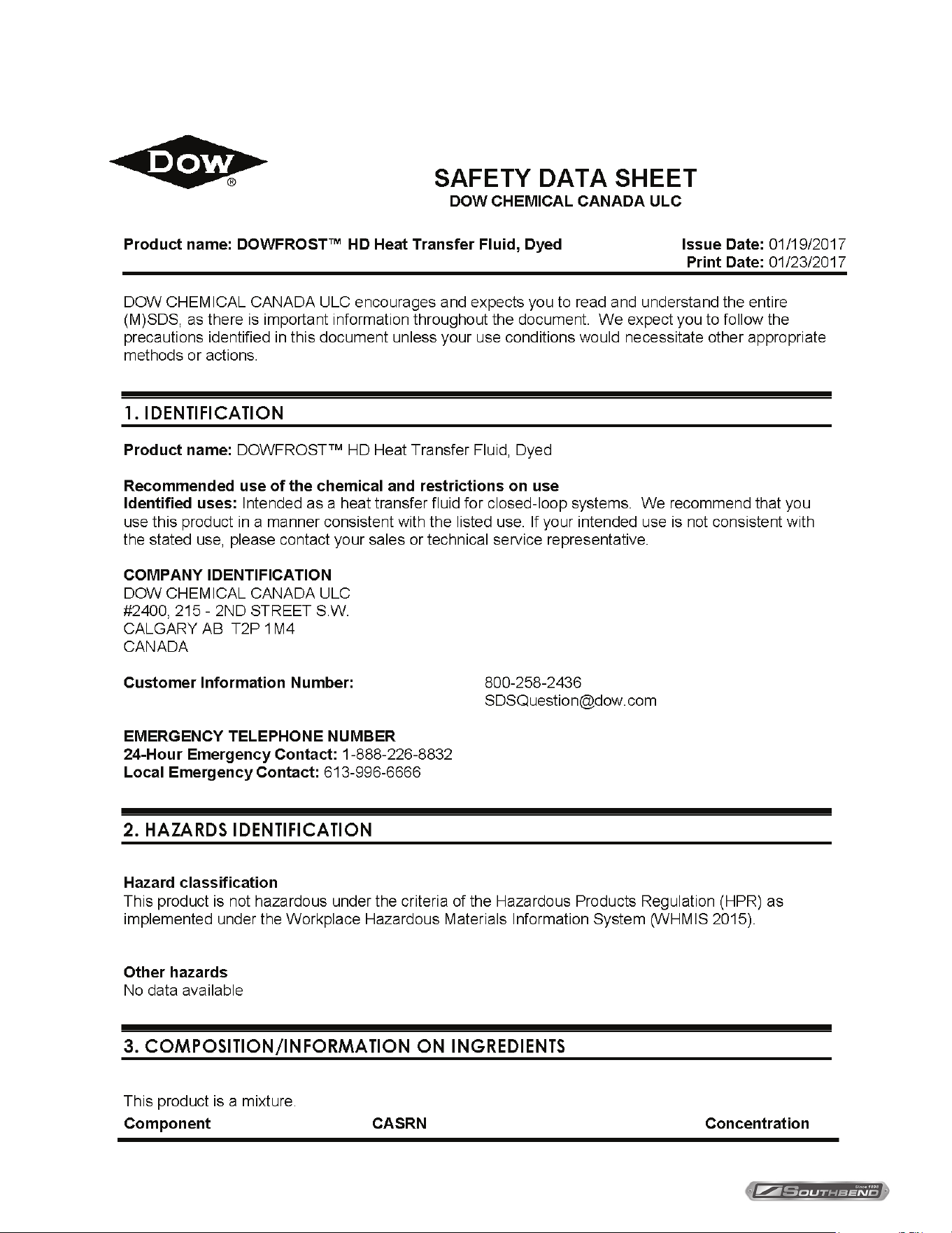
Troubleshooting
PROBLEM PROBABLE CAUSE
Unit does not come on
Power switch and/or thermostat is “OFF”.
Unit is not plugged in.
Main power supply is o.
Tilt micro switch out of alignment or faulty.
Unit is on electrically, but
does not heat
Gas supply to the unit is “OFF”.
The manual shut-o valve is “OFF”.
The thermostat is not turned “ON.”
The kettle is not in the upright position.
The electronic ignition is not functioning.
Pressure switch is not functioning.
Low water in kettle jacket.
Thermostat is not functioning.
Unit is slow to preheat and
slow to recover
Wrong size orices.
Wrong gas supply.
Incorrect pressure at supply.
Loss of vacuum.
NOTICE
Contact the factory, the factory representative or a local service company to perform maintenance and repairs.
INSTALLATION & OPERATION MANUAL 10105-SB REV 0 (04/21)
PAGE
16
OF 28
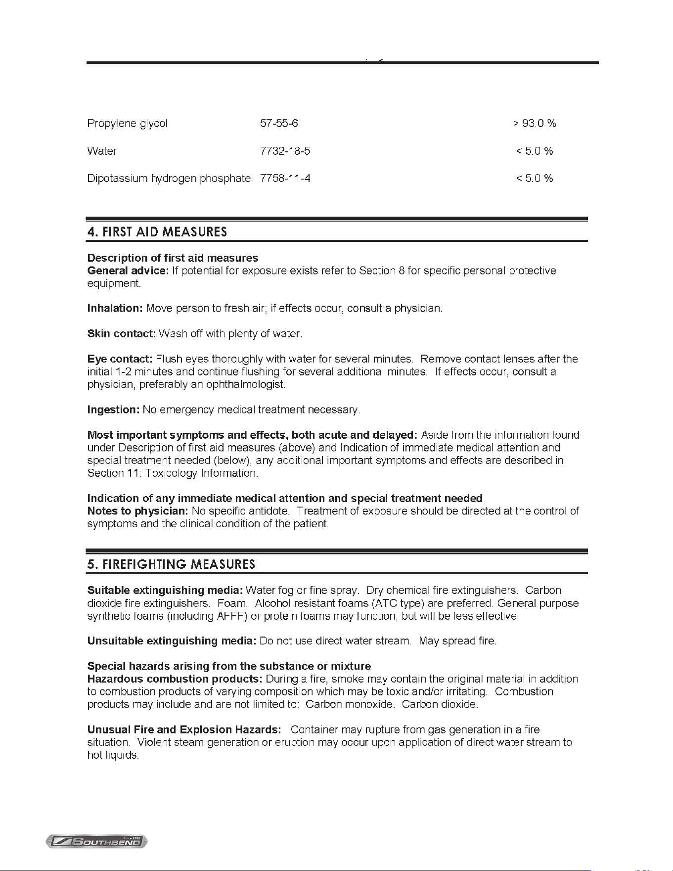
Gas Fired Steam Jacketed Tilting KettleMaterial Safety Data Sheets
Appendix ‘A’
INSTALLATION & OPERATION MANUAL 10105-SB REV 0 (04/21)
PAGE
17
OF28
Gas Fired Steam Jacketed Tilting Kettle Material Safety Data Sheets
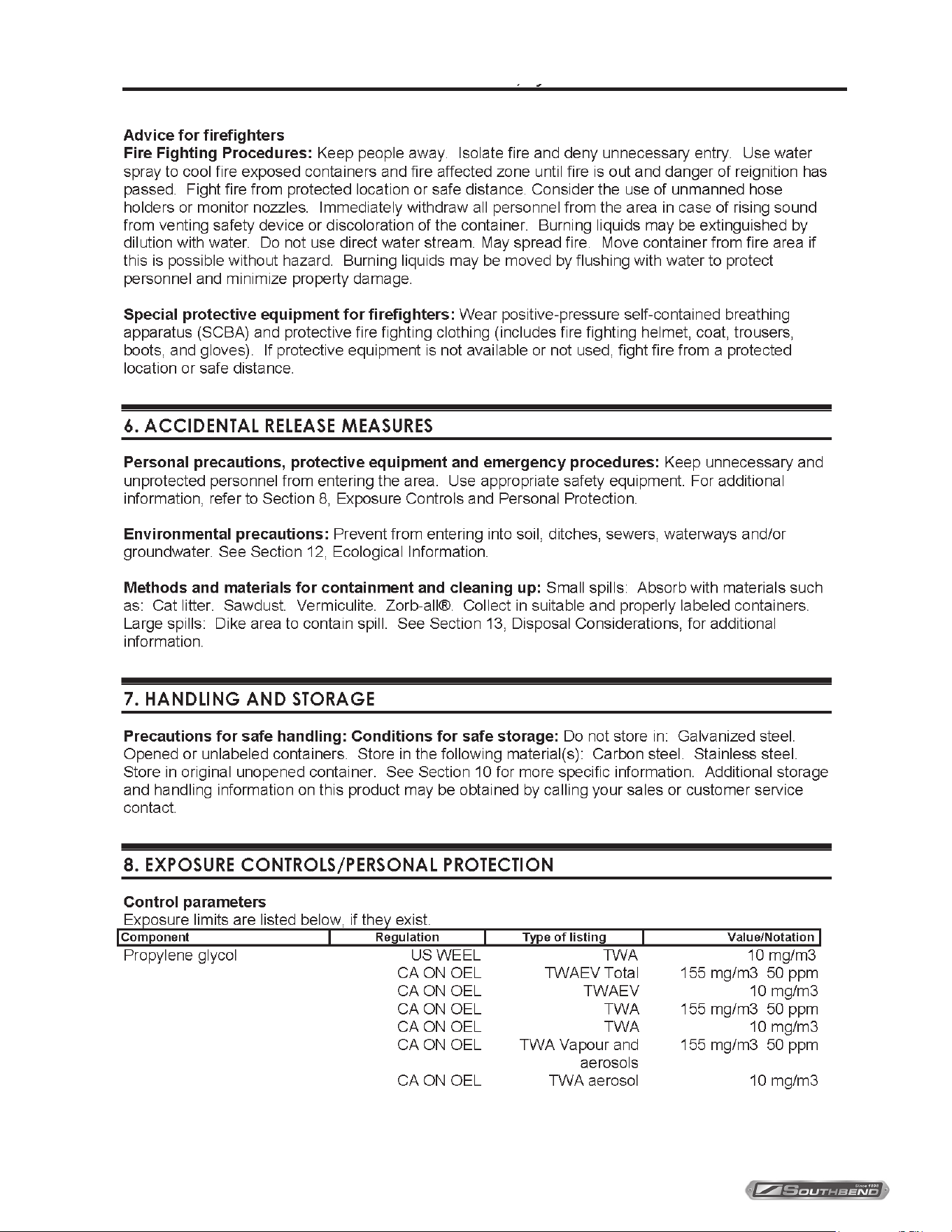
INSTALLATION & OPERATION MANUAL 10105-SB REV 0 (04/21)
PAGE
18
OF 28
Gas Fired Steam Jacketed Tilting KettleMaterial Safety Data Sheets
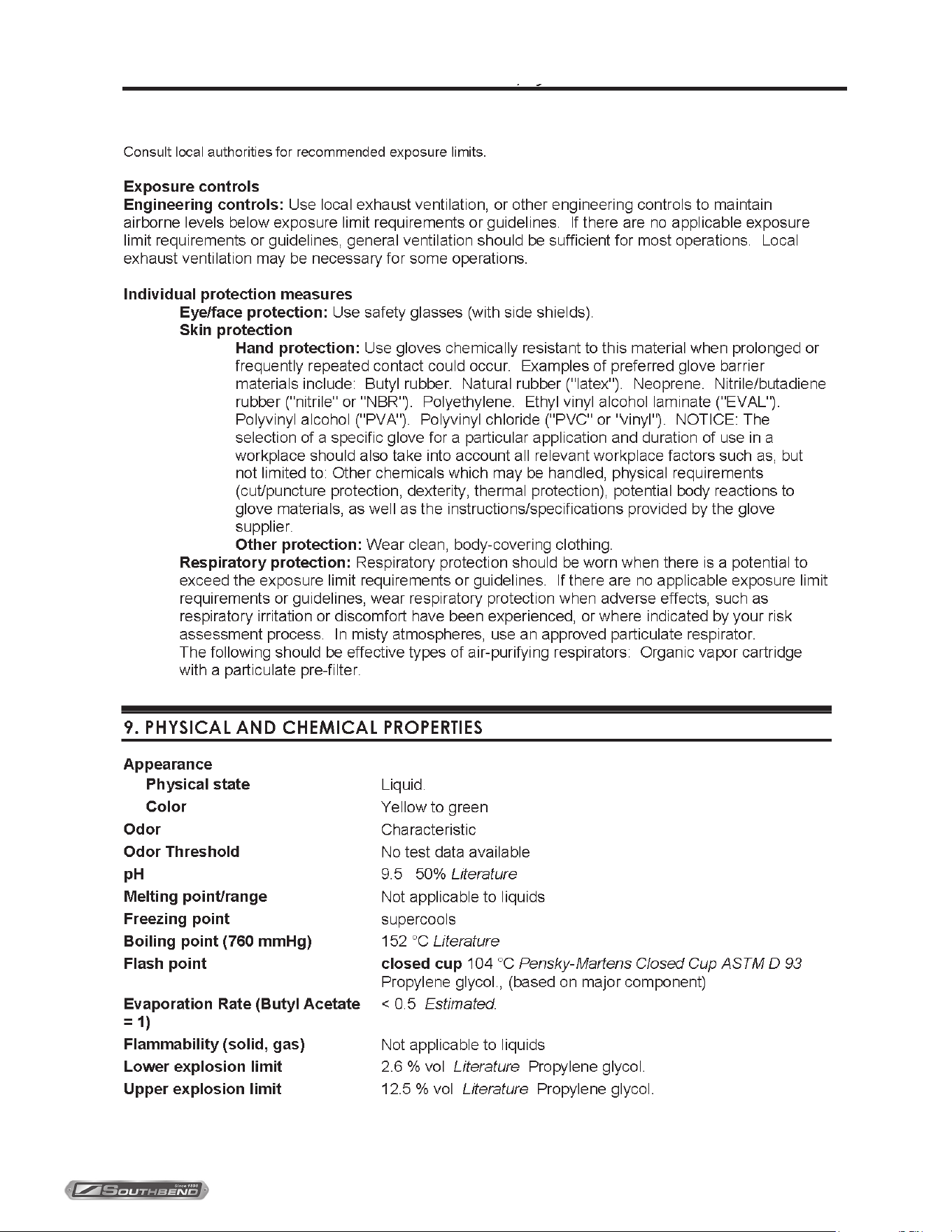
INSTALLATION & OPERATION MANUAL 10105-SB REV 0 (04/21)
PAGE
19
OF28
Gas Fired Steam Jacketed Tilting Kettle Material Safety Data Sheets
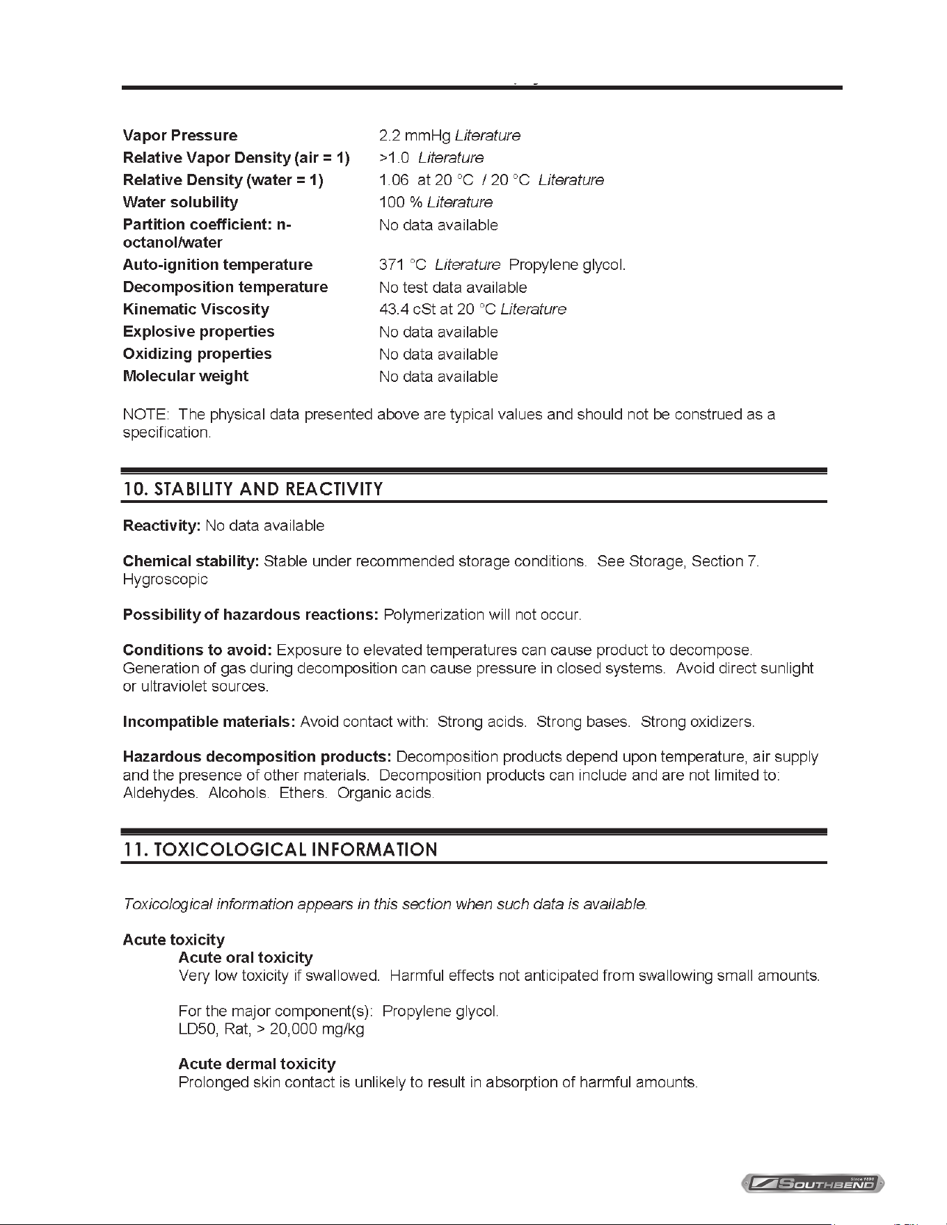
INSTALLATION & OPERATION MANUAL 10105-SB REV 0 (04/21)
PAGE
20
OF 28
Gas Fired Steam Jacketed Tilting KettleMaterial Safety Data Sheets
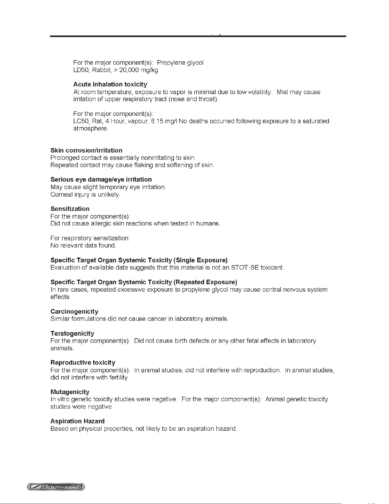
INSTALLATION & OPERATION MANUAL 10105-SB REV 0 (04/21)
PAGE
21
OF28
Gas Fired Steam Jacketed Tilting Kettle Material Safety Data Sheets
INSTALLATION & OPERATION MANUAL 10105-SB REV 0 (04/21)
PAGE
22
OF 28
Gas Fired Steam Jacketed Tilting KettleMaterial Safety Data Sheets
INSTALLATION & OPERATION MANUAL 10105-SB REV 0 (04/21)
PAGE
23
OF28
Gas Fired Steam Jacketed Tilting Kettle Material Safety Data Sheets
INSTALLATION & OPERATION MANUAL 10105-SB REV 0 (04/21)
PAGE
24
OF 28
Gas Fired Steam Jacketed Tilting KettleMaterial Safety Data Sheets
INSTALLATION & OPERATION MANUAL 10105-SB REV 0 (04/21)
PAGE
25
OF28
Gas Fired Steam Jacketed Tilting Kettle Notes

INSTALLATION & OPERATION MANUAL 10105-SB REV 0 (04/21)
PAGE
26
OF 28
Gas Fired Steam Jacketed Tilting Kettle
Notes
Notes

INSTALLATION & OPERATION MANUAL 10105-SB REV 0 (04/21)
PAGE
27
OF28
Gas Fired Steam Jacketed Tilting Kettle Notes
Notes
INSTALLATION & OPERATION MANUAL 10105-SB REV 0 (04/21)
PAGE
28
OF 28
Gas Fired Steam Jacketed Tilting Kettle
KGCT-12
Gas Fired Steam Jacketed
Tilting Kettle
A product with the Southbend Steam name incorporates the best in durability and low maintenance. We all recognize,
however, that replacement parts and occasional professional service may be necessary to extend the useful life of this
appliance. When service is needed, contact a Southbend Steam Authorized Service Agency, or your dealer. To avoid
confusion, always refer to the model number, serial number, and type of your appliance.
SOUTHBEND STEAM
1100 Old Honeycutt Road Fuquay-Varina, North Carolina 27526 USA
www.southbendnc.com