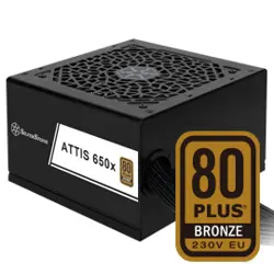

ATTIS 550x / ATTIS 650x / ATTIS 750Rx
ATTIS Series
80 PLUS Bronze 230V ATX PCIe 5 Fixed Cable Power Supply
▓
Compliant with ATX 3.1 standards and supports up to 2X power excursion
▓
High efficiency with 80 PLUS Bronze 230V certification
▓
24/7 continuous power output with 40℃ operating temperature
▓
Japanese primary capacitor
▓
Silent running 120mm fan with 18 dBA minimum
▓
Multiple protection circuitry
▓
Black flat embossed cable design
▓
Active PFC+Double forward+DC to DC Design
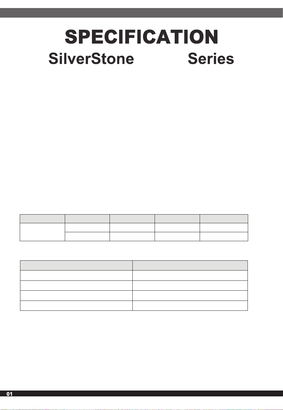
1. AC INPUT REQUIREMENTS
1.1 Input AC Voltage; Frequency
1.3 Inrush Current (Cold Start)
550W / 650W / 750W
ATTIS 550x / ATTIS 650x / ATTIS 750x
ATTIS
SST-AT550-BF / SST-AT650-BF / SST-AT750-BF
ATX Switching Power Supply
80 PLUS Bronze 230V efficiency certified
Summary
This power supply followed the INTEL psu Standard, with a total power of
500W-750W Comply with EU RoHS directive. Supports The INTEL HASWELL
platform. Meet the 80PLU Bronze efficiency standard.
The power supply must meet inrush requirements for any rated AC voltage,
during turn on at any phase of AC voltage, during a single-cycle AC dropout
condition, during repetitive ON/OFF cycling of AC, and over the specified
temperature range. The peak inrush current shall be less than the ratings of
its critical components (including input fuse, bulk rectifiers, and surge limiting
device), in the ambient temperature of 25℃, the output is no load, cold start
conditions: AC input is 230Vac, less than 130A.
1.2 Input Current Max
Rated Input Enable Input Min Nom Max
AC200-240V
Vrms 180 200-240 264
Hz 47
50-60
63
Mode 200-240V
500W
5A
550W
5A
650W
5A
750W
5A
1.4 Power Factor
The AC input voltage is Vin = 220Vac, and the power factor (PF) is
≥ 0.90 at ≥ 50% load.
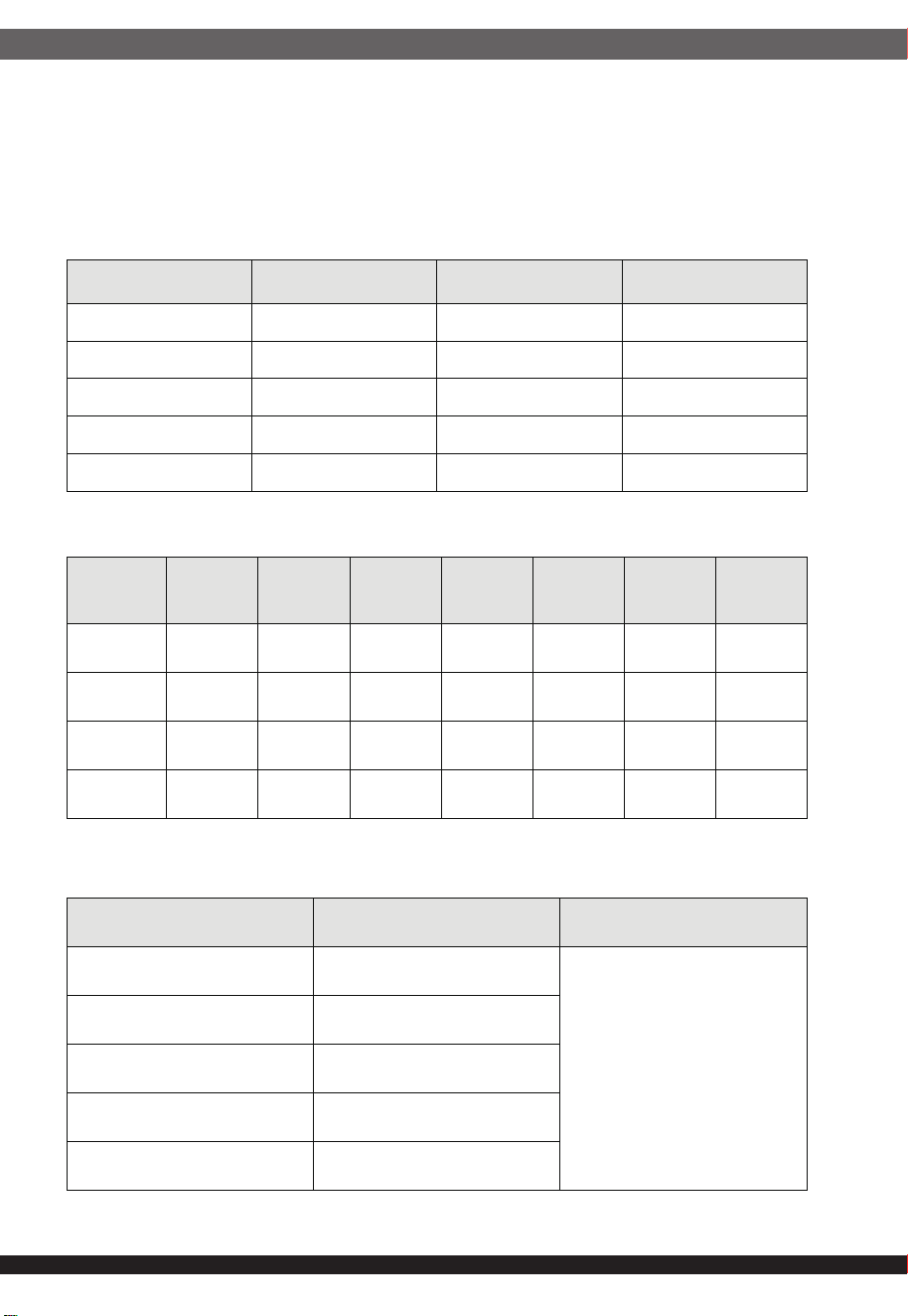
2.1 DC Output Voltage Range
2.2 DC Output
2.3 Dynamic Load Test
2. DC OUTPUT CHARACTERISTICS
DC Output Vnom
Load
Regulation
DC Output Range
+3.3V +3.3V ±5% ±5%
+5V +5.00V ±5% ±5%
+12V +12.00V +5%/-7% +5%/-7%
-12V -12.00V ±10% ±10%
+5VSB +5.00V ±5% ±5%
Model Name
3.3V 5V
Combine
Rated
Power
12V -12V 5VSB
Total
Power
500W
20A 20A 100W 41.6A 0.3A 2.5A 500W
550W
20A 20A 100W 45.8A 0.3A 2.5A 550W
650W
20A 20A 100W 54.1A 0.3A 2.5A 650W
750W
20A 20A 100W 62.5A 0.3A 2.5A 750W
DC Output Step Load Remarks
+5Vdc 1A/us
Simulate PSU at transient
response
20% to 50% load situation
(Load changing repetition rate:
20msec/1msec)
+3.3Vdc 1A/us
+12Vdc 5A/us
-12Vdc 0.1A/us
+5Vsbdc 0.1A/us
02
03
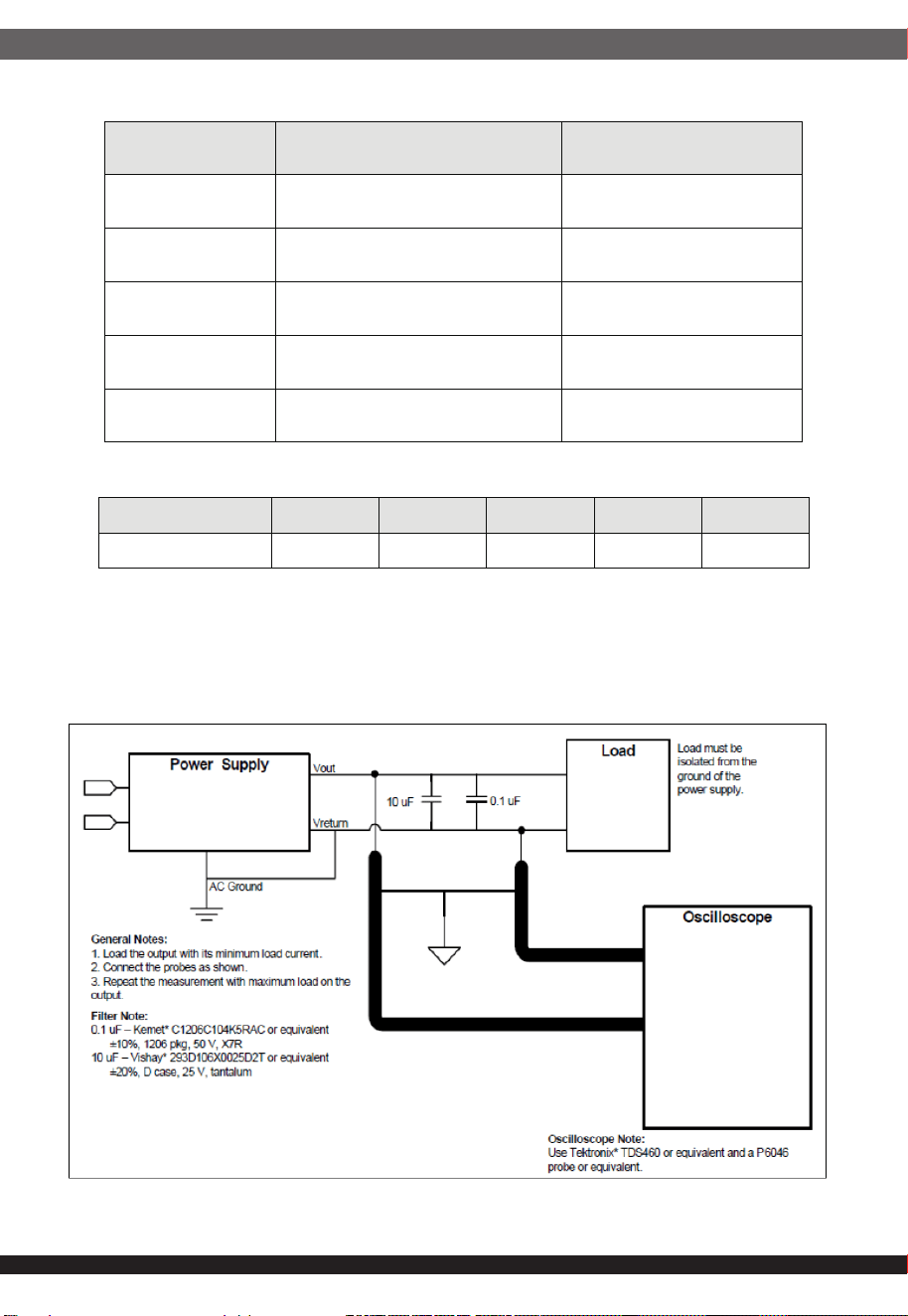
2.4 Capacitor Load
2.5 Ripple & Noise
Schematic Diagram Of Measurement Method
Note: 1. Use oscilloscope with 20MHz bandwidth for test.
2. When measuring, connect a 0.1µF porcelain capacitor and a 10µF
electrolytic capacitor between the output end and the ground.
DC Output Capacitive load
Remarks
+5Vdc
3300
uF
+3.3Vdc
3300
uF
+12Vdc
6600
uF
-12Vdc
330
uF
+5Vsbdc
3300
uF
DC Output +5V +12V +3.3V -12V +5VSB
Ripple & Noise(mVp-p) 50mV 120mV 50mV 120mV 50mV
04
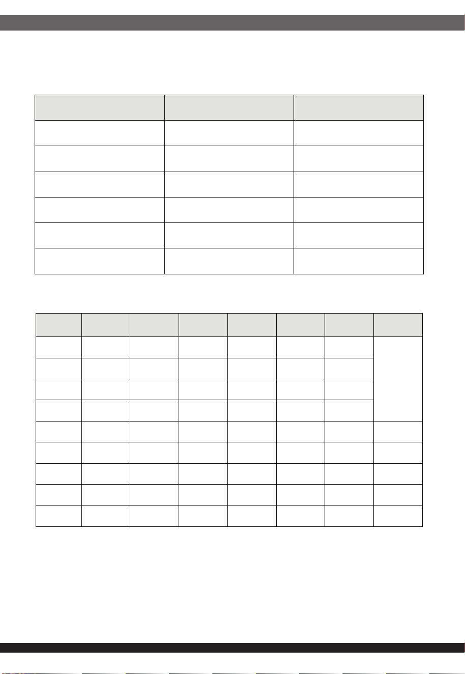
2.6 Efficiency
2.6.2 Power Efficiency Of Whole Machine
2.6.1 Standby Power Consumption
The DC output voltage overshoot caused by switching AC power supply or
PS_ON# should be less than 10% of the normal output, and no reverse polarity
voltage will be generated.
2.7 DC Output Overshoot
Load Condition
Efficiency
Remark
45mA ≥45% ErP* Lot 6 2013
90mA ≥45% ErP* Lot 6 2010
0.55A ≥75% ALPM and ErP* Lot 3 2014
1.0A ≥75% Recommend
1.5A ≥75% ALPM and ErP* Lot 3 2014
3.0A ≥75% Recommend
Loading White Bronze Silver Gold Platinum Titanium
Low Load
10W/2%
10%
20% 82% 85%
50% 85% 88%
100% 82% 85%
500W - √ - - - - 10W
550W - √ - - - - 11W
650W - √ - - - - 13W
750W - √ - - - - 15W
850W - √ - - - - 17W
05
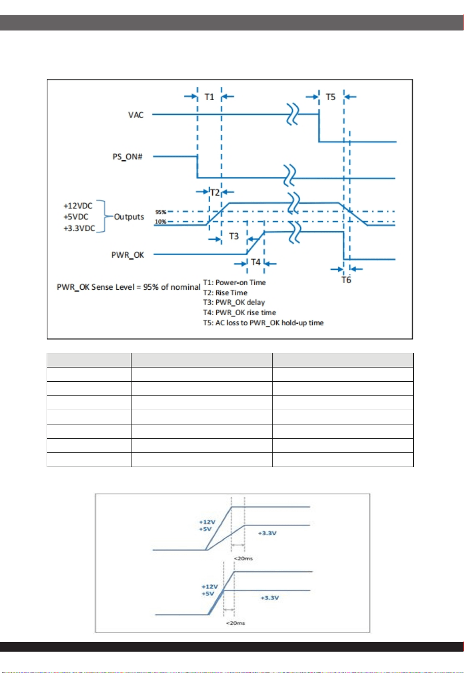
2.8 Logical timing and control signals
2.8.1:Timing
2.8.2 +5V And +3.3V Timing Requirements
Parameter Description Required
T0 AC Power On Time T0<2s
T1 Power Start Time T1≤150mS
T2 Voltage Rise Time 0.2mS≤T2≤20mS
T3 Pwr_Ok Delay Time T3≤150mS
T4 Pwr_Ok Rise Time T4≤10mS
T5 AC Power Off Maintenance Time
T5≥12mS(70% Load)
T6 Power Failure Warning Time
T6>1mS(70% Load)
06
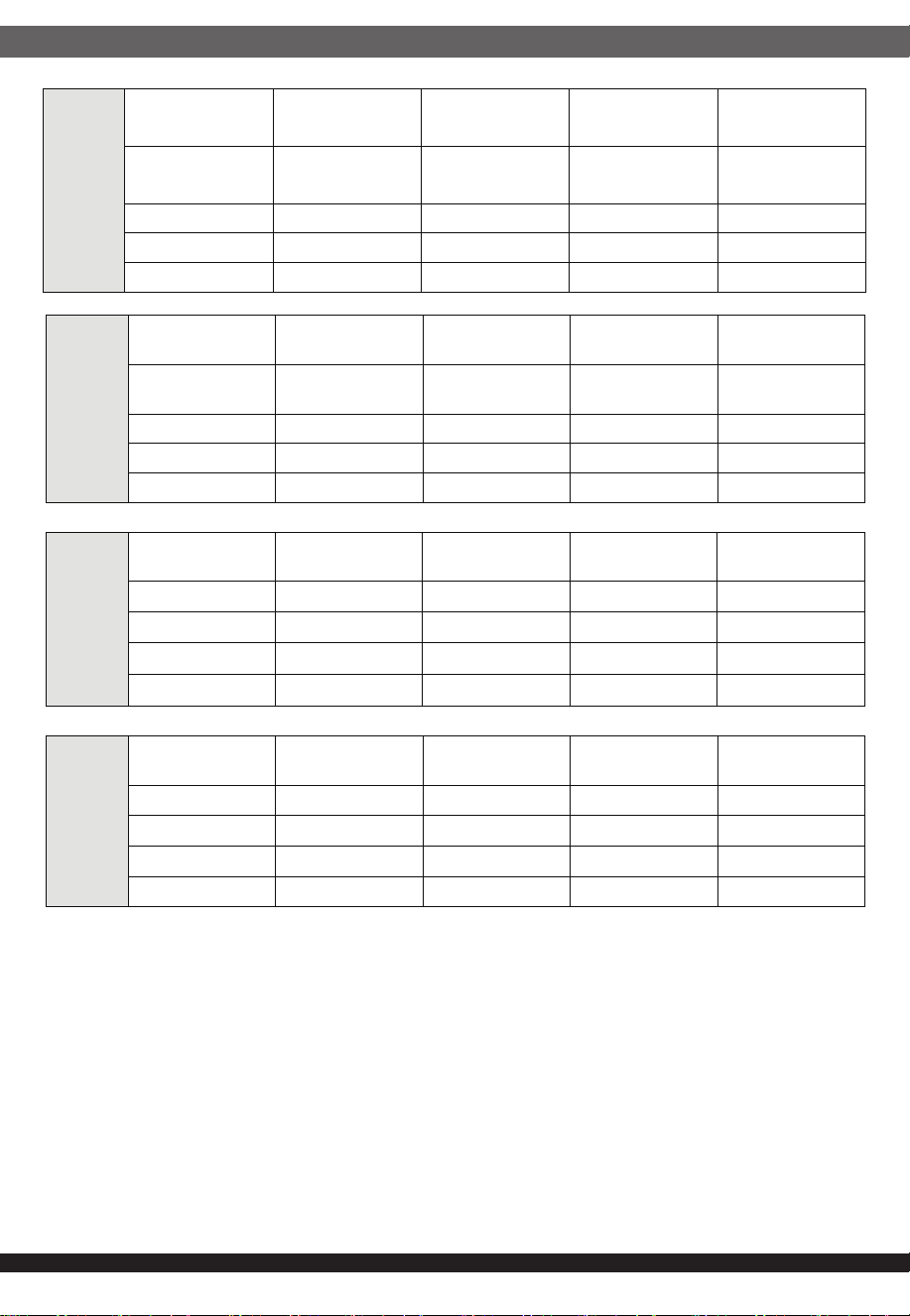
Duty Cycle Test Criteria for a 750W PSU – RMS
Duty Cycle
Time Constant
(TC)
Time for Power
Excursion (TE)
Power @ TC
Power @ TE
5% 1900 µs 100 µs 688.2W 1500 W
8% 11.5ms 1ms 673W 1350W
12.5% 70ms 10ms 661.2W 1200W
25% 300 ms 100 ms 692.8W 900W
2.9 PWR_OK/PS_0N#
2.9.1
PWR_OK signal is a 5V TTL signal. PWR_OK signal will be high level after
100-150ms delay when the DC output voltage reaches the minimum detection time
after starting. The PWR_OK signal is low when any DC output is below the lowest
detection level.
2.9.2
2.10 +5VSB Characteristics
PS_ON# signal is TTL compatible signal, the motherboard through PS_ON# signal
to control the switch of the power supply. When the PS_ON# signal is low,
the power supply is turned on; when the PS_ON# signal is high, the power supply
is turned off.
As long as there is an AC voltage input, +5Vsb has an output voltage, and +5VSB
provides power output for the computer in standby mode.
Signal types
+5V TTL
Logical low level
<0.4V,sink current 4mA
Logical high level
2.4V-5V source current 200µA
High-pass output impedance
1KΩ ±5%
Min Max
VIL Input Low Level Voltage 0.0V 0.8V
IIL (Vin=0.4V)
Input Low Level Current (Vin=0.4V)
-1.6mA
VIH (Iin = -200μA)
Input High Level Voltage (Iin =-200μA)
2.0V
07
3.1 Operation
3.2 Shipping And Storage
3.3 Altitude
5.1 OPP Test
3. ENVIRONMENTAL REQUIREMENTS
4. HEAT DISSIPATION AND NOISE
5. PROTECTION
Air cooling is adopted for heat dissipation, and the power fan circuit has the
function of temperature control and speed regulation, and the noise meets
the relevant requirements of GB/T14714.
Temperature
0
o
C to 40
o
C
Relative Humidity
10 to 90%, non-condensing
Temperature
-20
o
C TO 70
o
C
Relative Humidity
5 to 95%, non-condensing
Operating
16404.2FT max
Storage
50032.81FT max
Power supply due to over voltage, over power, short circuit, over current, over
temperature, under voltage, protection function circuit action, electricity from the
lock, no output at this time; When these reasons are removed, restart the power
supply and the power supply will return to the normal output state. Reset
PS_ON# for at least 1 second; Ac power off for at least 10 seconds)
After power overpower protection, the power supply does not output and is
locked. Its output load rises at a rate of at least 5A/ us from full load, and the
power of protection action is greater than 110% and less than 170%.
08
5.1 OPP Test
5.2 Over Voltage Protection
5.3 Short Circuit Protection
5.4 Over Current Protection
After power overpower protection, the power supply does not output and is
locked. Its output load rises at a rate of at least 5A/ us from full load, and the
power of protection action is greater than 110% and less than 170%.
A. The power supply can be protected and locked when the output of each
main power supply except +5VSB shorts to the ground.
B. If the +5VSB output is short-circuited to the ground, the +5VSB output does
not output. If the short-circuit is canceled, the system automatically recovers.
A. Power protection when the temperature +5VSB output overcurrent. +5VSB
will automatically recover after the overcurrent is cancelled.
B. +12V; +5V; +3.3V output overcurrent, power protection and lock no output.
Cancel the overcurrent and restart the PS/ON.
C. -12V does not perform an overcurrent protection test
Note: +3.3V and +5V are DC-DC, and OVP of external irrigation test is cancelled.
+12V is synchronous rectifier output, and OVP of external irrigation test is
cancelled.
DC Output
Protect Action Output Voltage
Unit
Min Nom Max
+12V 13.4 15.0 15.6 V
+5V 5.74 6.3 7.0 V
+3.3V 3.76 4.2 4.3 V
+5VSB 5.74 6.3 7.0 V
Model
+3.3V +5V +12V 5VSB
Min Max Min Max Min Max Min Max
500W
22A 40A 22A 40A 50A 70.8A 3.0A 5.0A
550W
22A 40A 22A 40A 55A 77A 3.0A 5.0A
650W
22A 40A 22A 40A 65A 92A 3.0A 5.0A
750W
22A 40A 22A 40A 75A 106A 3.0A 5.0A
5.5 Over Temperature Protection
When the ambient temperature of the power supply exceeds the specification
range, the power supply is locked and protected.
5.6 Under Voltage Protection
Power protection when under voltage occurs at each source output of the
power supply
5.6 Under Voltage Protection
Power protection when under voltage occurs at each source output of the
power supply
6.1 Test Condition:
Follow As Below Condition Table.
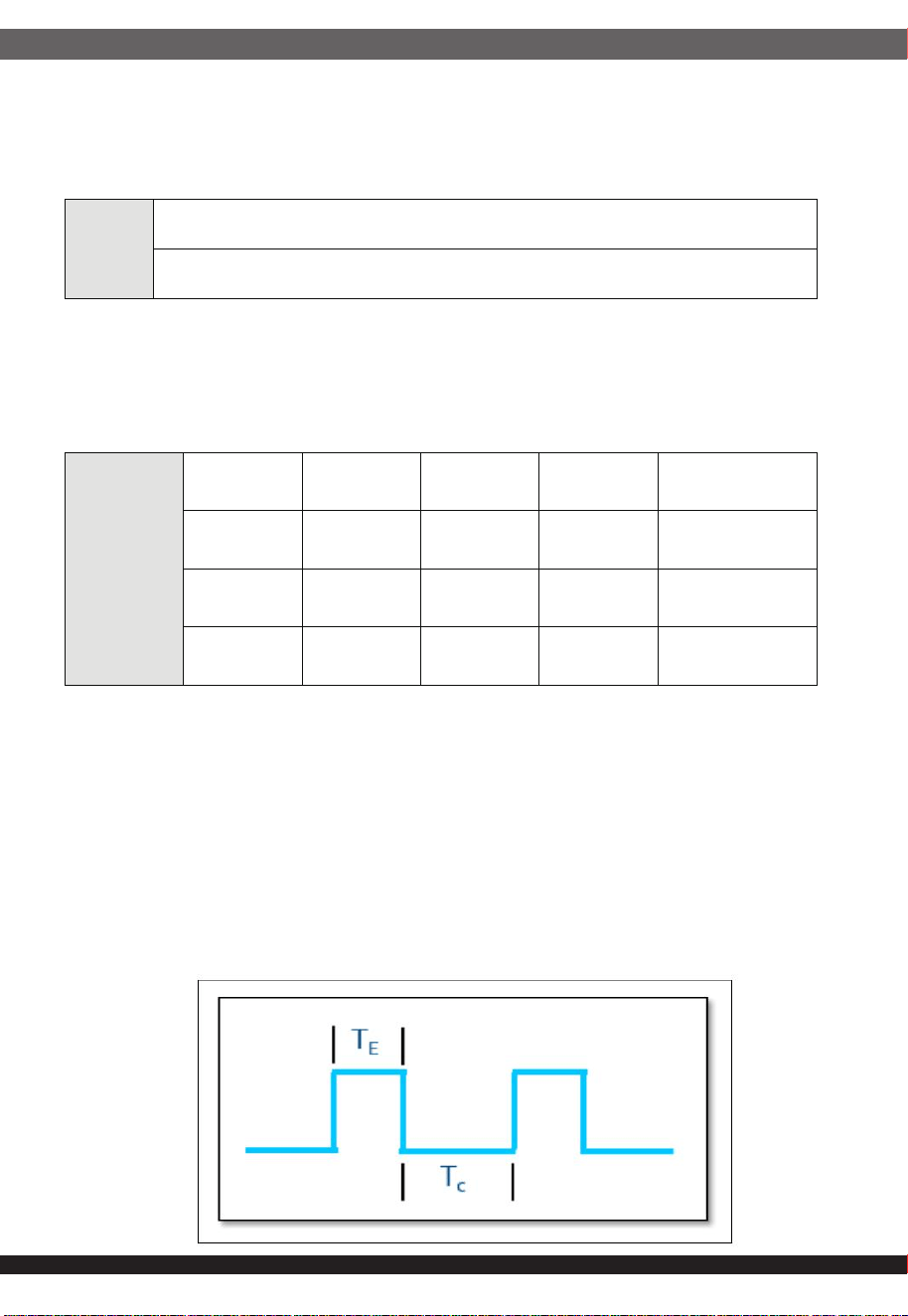
Duty Cycle Definition :
OTP
Temperature range
50
℃
-65
℃
UVP
Vo Min Normal Max Unit
+3.3V 2.55 2.69 2.83 V
+5V 4.1 3.43 4.47 V
+12V 9.5 10 10.5 V
6. PCIe* AIC PEAK POWER DUTY CYCLE TEST
09
10
500W
Duty Cycle
Time Constant
(TC)
Time for Power
Excursion (TE)
Power @ TC Power @ TE
5% 1900 µs
100 µs
458.8W
1000W
8% 11.5ms
1ms
448.7W 900W
12.5% 70ms
10ms
440.8W 800W
25% 300 ms
100 ms
461.9W 600W
550W
Duty Cycle
Time Constant
(TC)
Time for Power
Excursion (TE)
Power @ TC Power @ TE
5% 1900 µs
100 µs
504.7W
1100W
8% 11.5ms
1ms
493.5W 990W
12.5% 70ms
10ms
484.9W 880W
25% 300 ms
100 ms
508.1W 660W
650W
Duty Cycle
Time Constant
(TC)
Time for Power
Excursion (TE)
Power @ TC Power @ TE
5% 1900 µs
100 µs
596.3W 1300W
8% 11.5ms
1ms
583.3W 1170W
12.5% 70ms
10ms
573W 1040W
25% 300 ms
100 ms
600.4W 780W
750W
Duty Cycle
Time Constant
(TC)
Time for Power
Excursion (TE)
Power @ TC Power @ TE
5% 1900 µs
100 µs
688.2W 1500W
8% 11.5ms
1ms
673.0W 1350W
12.5% 70ms
10ms
661.2W 1200W
25% 300 ms
100 ms
692.8W 900W
6.2 Test Purpose
Simulate PSU at above table duty cycle 5%, 8%, 12.5%, 25% load situation.
Test input voltage at low line and high line, 10min test time for each Duty Cycle part.
11
A. Meet Standard Requirements
7. ELECTROMAGNETIC COMPATIBILITY
8. INSULATION AND SAFETY SPECIFICATIONS
9. Dimension
150 x 86 x140mm
NO.
Item Calibration (or test conditions)
7.1
Conducted interference EN55035 CLASS B
7.2
Radiated interference EN55035 CLASS B
7.3
Electrostatic immunity IEC-61000-4-2 CLASS B
7.4
Conduction immunity IEC61000-4-6 CLASS A
7.5
Radiation immunity IEC61000-4-3 CLASS A
7.6
Surge IEC61000-4-5 CLASS B
7.7
Harmonic current EN61000-3-2 Class D.
NO. Item
Calibration (or test
conditions)
Remark
8.1
The electric
strength
Input
and output
3000Vac
(
4242dc
)
/10mA/3s
No arc, no
Breakdown
Input and earth
1800Vac
(
2546Vdc
)
/10mA/3s
Insulation
impedance
500Vdc, 10MΩ Min.
8.2 Leakage current
﹤3.5mA(264Vac,50Hz)
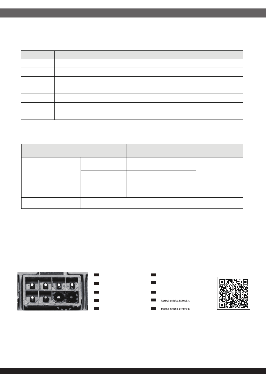
10. Power Supply Connector Overuse Definition
Definition einer Überlastung des
Netzanschlusses
DE
Définition de l'utilisation excessive du
connecteur d'alimentation électrique
FR
Definizione di uso eccessivo del connettore
di alimentazione
IT
Definición de uso excesivo del conector de
la Fuente de alimentación
ES
Определение чрезмерной нагрузки на
коннектор блока питания
RU
電力供給コネクタの使用限度超過に関する説明
JP
CN
TW
ขีดจำกัดการรองรับการใช้งานของขั้วต่อจากพาวเวอร์ซัพพลาย
TH
전원 공급 커넥터 과용 정의
KR
12
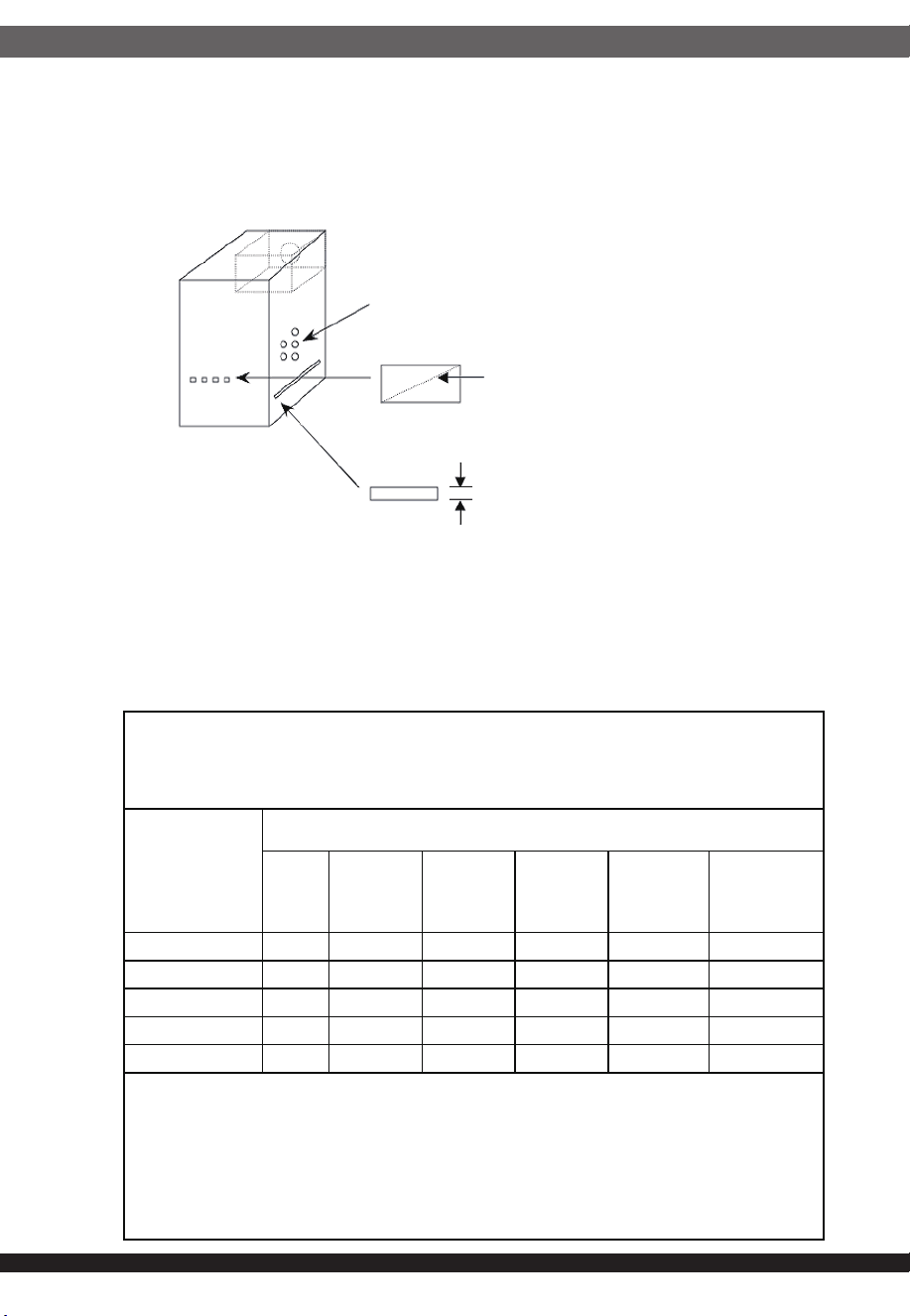
1. 為了保護使用者及防火的目的,安裝此交換式電源供應器時,必須安裝於符合下列各項要求的外殼中,
並且安裝妥善後,才可接上電源。
1-1. 外殼材質須為防火外殼。外壳材质须为防火外壳。
1-2. 外殼的上方及側邊之圓形開孔,最大內徑不可大於5mm。
1-3. 外殼的上方及側邊之長條型開孔,對角線距離不可大於5mm;若寬度小於1mm,則長度不受限制。
1-4. 外殼底部不可有開孔。外壳底部不可有开孔。
直徑不大於5mm
對角線不大於5mm
寬度小於1mm 則長度不限
Openings that do not exceed 1mm in width regardless of length
Openings that do not exceed 5mm in any dimension
2. 本產品輸出含有危險能量,為避免操作時發生危險,須於裝入系統機殼並將所有設備安裝妥當後才可開啟電源。
3. 本產品之電源輸出非屬電力限制型電源,請連接使用具防火外殼之周邊,以避免火災危險發生。
公司名稱:銀欣科技股份有限公司
公司地址:新北市中和區建康路168號12樓
BSMI ROHS 資訊
https://www.silverstonetek.com/upload/downloads/PSU/RSD.pdf
設備名稱:
:
電源供應器 型號(型式)
單元Unit
限用物質及其化學符號
鉛
Lead
(Pb)
汞
Mercury
(Hg)
鎘
Cadmium
(Cd)
六價鉻
Hexavalent
chromium
(Cr
+6
)
多溴聯苯
Polybrominated
biphenyls
(PBB)
多溴二苯醚
Polybrominated
diphenyl ethers
(PBDE)
金屬外殼
○
○ ○ ○ ○ ○
電路板組成
○
○ ○ ○ ○ ○
風扇
○
○
○
○
○
○
線材
○ ○ ○ ○ ○ ○
輸出接頭
○ ○ ○ ○ ○ ○
備考1.〝超出0.1 wt %〞及〝超出0.01 wt %〞係指限用物質之百分比含量超出百分比含量基準值。
備考2.〝○〞係指該項限用物質之百分比含量未超出百分比含量基準值。
備考3.〝-〞係指該項限用物質為排除項目。
Equipment name
Type designation (Type)
Restricted substances and its chemical symbols
Note 1
:
“Exceeding 0.1 wt %” and “exceeding 0.01 wt %” indicate that the percentage content of the restricted substance exceeds the
reference percentage value of presence condition.
Note 2
:
“
○
” indicates that the percentage content of the restricted substance does not exceed the percentage of reference value of presence.
Note 3:The “−” indicates that the restricted substance corresponds to the exemption.
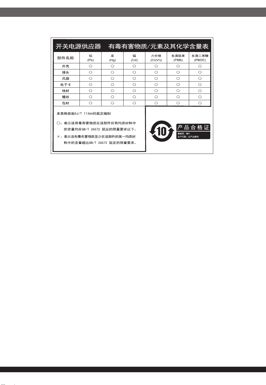
SST-AX0750FCBR-A; SST-AX0650FCBR-A
13
This device complies with Part 15 of the FCC Rules.
Operation is subject to the following two conditions:
(1) this device may not cause harmful interference, and
(2) this device must accept any interference received,
including interference that may cause undesired operation.
Please refer to SilverStone website for latest specifications updates.
※付属の電源コードは当該製品専用です。他の機器に使用しないでください。
The equipment a Class | Switching Power Supply intended to use
for information technology equipment or Audio and Video equipment.
Model (safety certification): SST-AX0550FCBR-A / SST-AX0650FCBR-B /
SST-AX0750FCBR-B