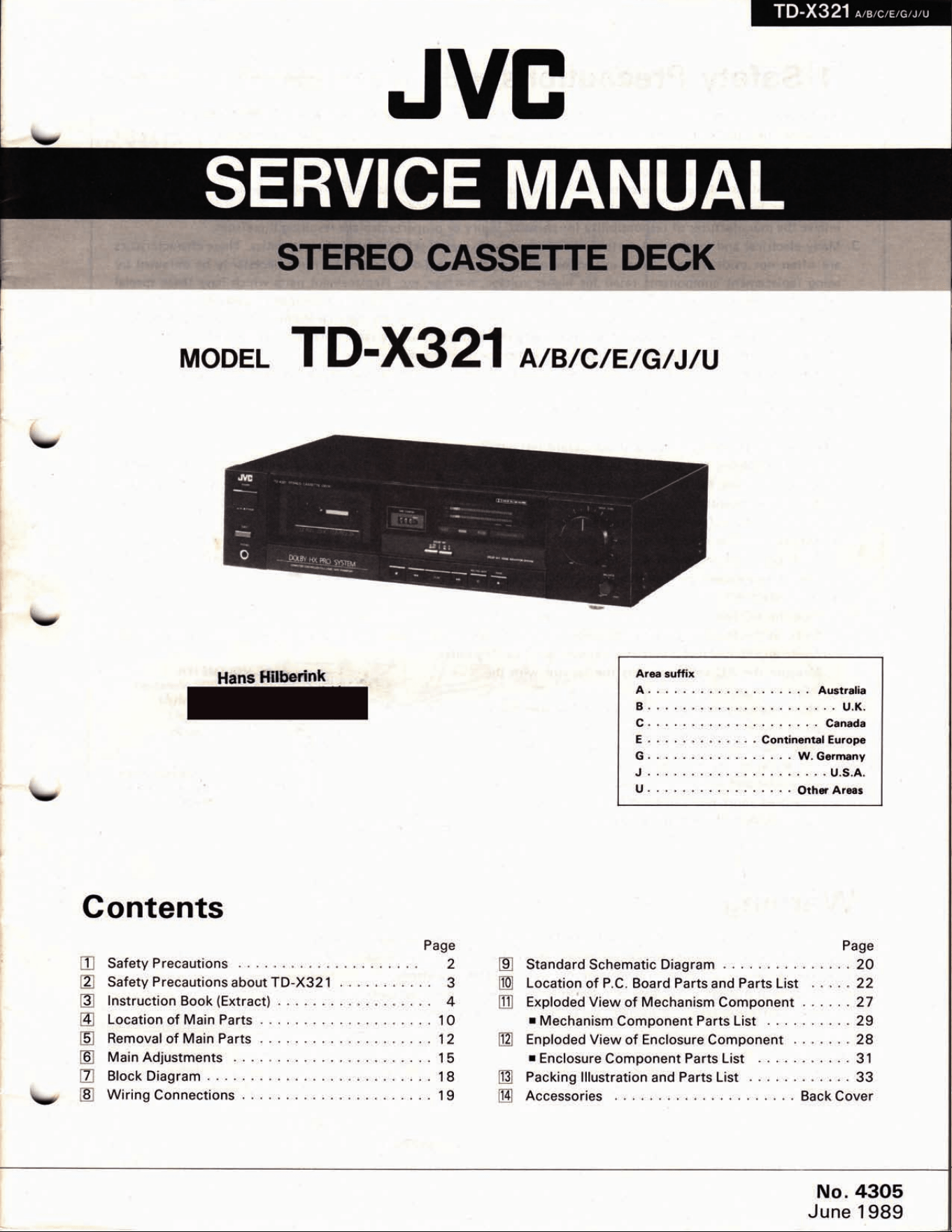
TD-X321
*",c,e,eu,u
I
tr
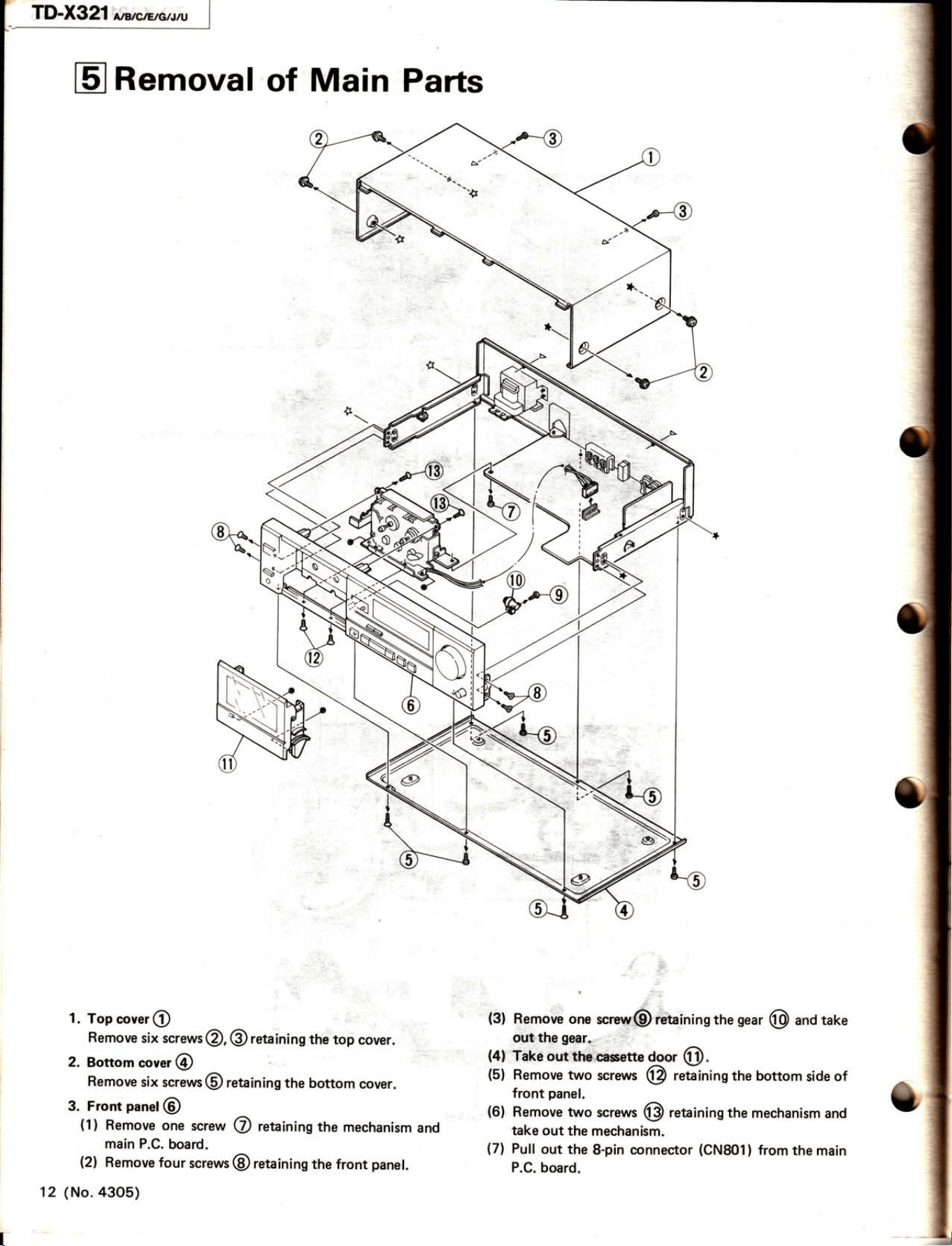
Removal
of Main
Parts
1.
Top
cover
@
Remove
six screws
@,
@
retaining
the
top
cover.
2.
Bottom
"or"r
@
Remove
six
screws
@
retaining
the
bottom
cover.
3. Front
panet
@
(1)
Remove
one
screw
@
retaining
the
mechanism
and
main P.C.
board.
(2)
Remove
four
screws
@
retaining
the front
panet.
(No.
a3o5)
(3)
Remove
one
s"rew@ retaining
the
gear
@
and
take
out
the
gear.
(4)
Take
out
the
cassette
ggor
@.
(5)
Remove
two
screws (p
retaining the bottom
side
of
front
panel.
(6)
Remove
two
screws
@
retaining the
mechanism
and
take out
the
mechanism.
(7)
Pull
out the
8-pin connector
(CN801)
from
the
main
P.C.
board.
12
TD-X321
agrcftrc..w
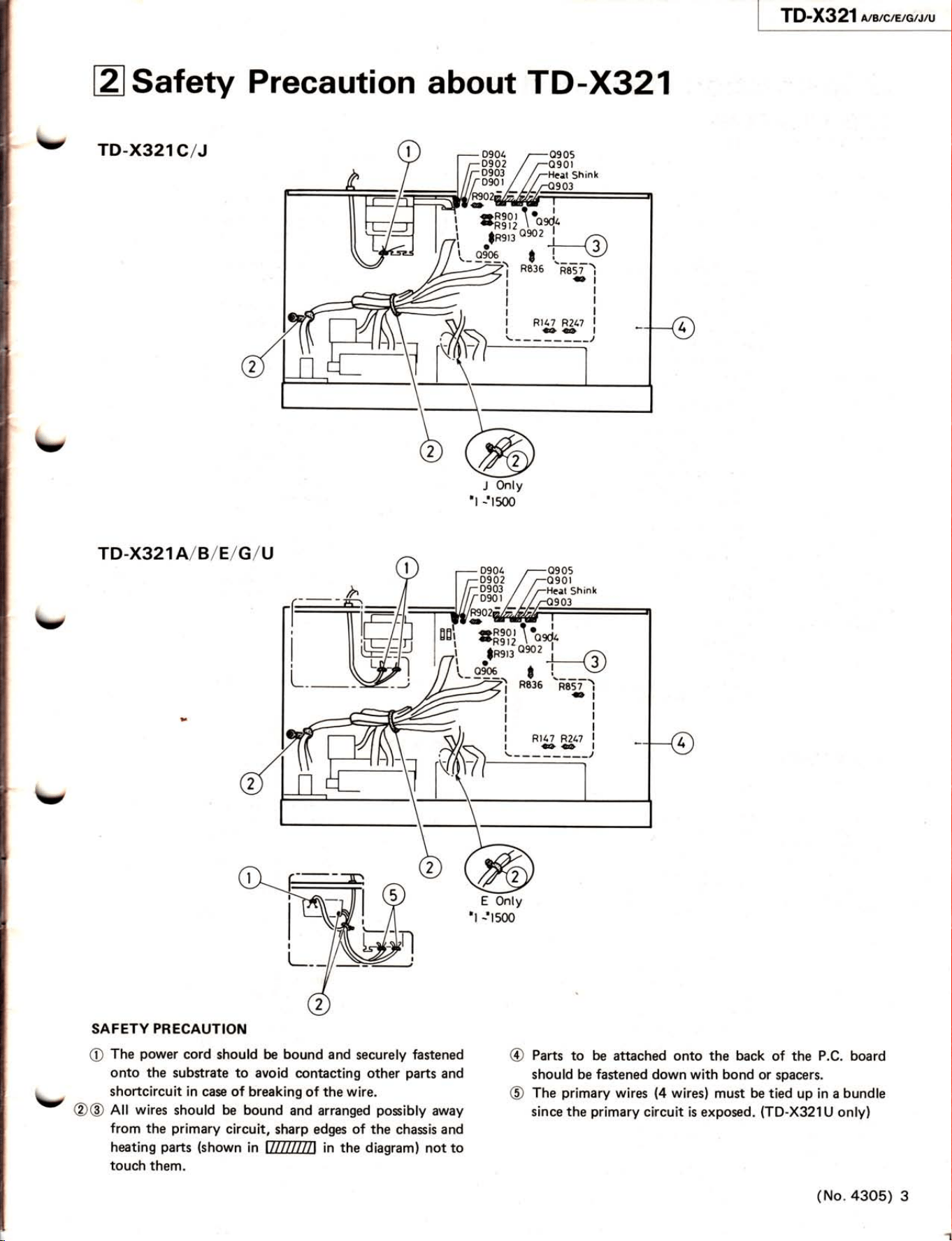
esafety
Precaution
about TD
-X321
\,
TD-x32
1c/J
TD.X321A/B/E/G/U
SAFETY
PRECAUTION
@
The
power
cord
should be
bound
and
securely fastened
onto the substrate
to avoid
contacting other
parts
and
shortcircuit in
case of breaking
of the wire.
@@
All wires
should be bound
and arranged
posibly
away
from the
primary
circuit,
sharp edges
of the
chasis and
heating
pans
(shown
in
ÏTïTïfnT
in the diagram)
not to
touch
them.
\,
\í
@
@
Parts
to
be
attached onto the back
of the
P.C. board
should be fastened down with bond or
spacers.
The
primary
wires
(4
wires)
must
be
tied
up in a
bundle
since
the
primary
circuit
is exposed.
(TD-X321U
only)
0904
0902
0903
v
(No.
43o5)
3
\
TD-X321
,irwctltctrtt)
COMPU
LINK
CONTROL
SYSTEM
This is
a
convenient
system
which
has
been
originated and
developed
by
JVC.
Tha
follow-
ing are the
brief explanations
of
its major
per-
formances:
Automatic
Source Selection
When
the
provided
remote
cables
are used
for
connecting this
unit
to
other
Gomponents
which
have
COMPU
LIN
K-l
/SYNCH
RO
ter-
minals,
the
switchover
of
all
system
components
is
possible
with
simple
one-touch
of
the
source
selector
button
of
JVC's
amplifier
or
rsc€iwr.
By
doing this, the
corresponding
@mponent
will
start
playing
automatically.
The
source
select
button
of the
remote control
unit or
the
activation
button
of
the
desired cofnponent
can
be
also
used
for this
purpose.
When
the
components
have been
srruitched
over,
the
previous
component
will stop
play,ing
with.
in five
seconds.
Synchronized
Record ing
Synchronized
recording
refers
to
the
pro@ss
in
which the deck
srarts recording
in
ryn-
chronism
with
the CD
player.
Perform
the
ryn-
chronized
recording
as follows:
1.
Set
the
cassette
deck
to
the
record-pause
mode in
accordance
with the
recording
pro-
cedures
on
page
19.
2.
lf
you
want the
programmed
recording,
pro-
gram
the
desired
tunes in
any
order
you
wish to
hear.
3.
Press
the PLAY/PAUSE
button
óf
the
CD
player.
By
so
doing, the cassette
dcck is
placed
in the record
mode
and syndrronizod
with
the CD
ptayer
for
recording.
Synchro-
nized
recording
thus
can be
made
po*íbto.
Notes:
o
Synchronized recording
stops automatically
when the CD
player
stops
playing.
o
To cancel
synchronized
recording,
press
the
STOP
button
of the
CD
player
or cassette
deck.
o
Synchronized
recording
does not
start
excspt
when the
record-;rause
mode is
set
by
simul-
taneously
pressing
the
O
REC/RE€
MUTE
arrd l!
(pause)
buttons
in the stop
rnode.
o
The source
is
locked
to
the
CD
position
dur-
ing
synchronized
recording to
avoid
accldenÍal
stops or
switch-over
to another
corriponont.
To
switch over
the
components,
cancel
synchronized
recording f
irst
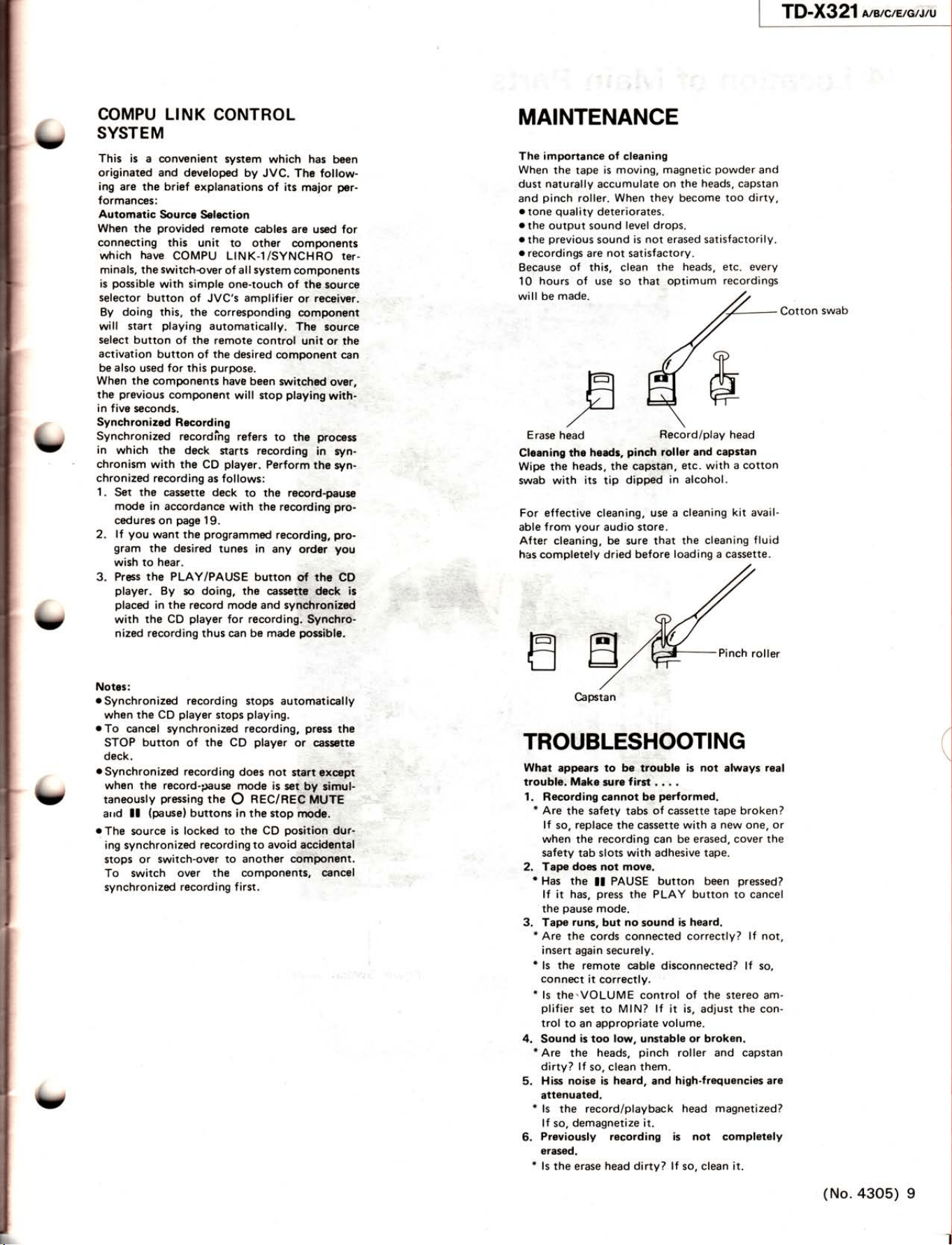
MAINTENANCE
The
importance
of
cleaning
When
the
tape
is
moving,
magnetic
powder
and
dust naturally
accumulate
on
the
heads,
capstan
and
pinch
roller.
When
they become
too
dirty,
o
tone
quality
deteriorates.
o
the
output sound
level
drops.
othe
previous
sound
is not
erased
satisfactorily.
r
recordings
are
not
satisfactory.
Because of
this, clean
the
heads,
1
0
hours
of
use
so that
optim
um
will be
made.
E
rase
Cleaning the
headr,
pinch
roller
and
capstan
Wipe the
heads,
the
capstan,
etc.
with
a
cotton
swab
with
its
tip
dip@
in alcohol.
For effective cleaning,
use a
cleaning
kit
avail-
able
f
rom
your
audio store.
After
cleaning,
be
sure that
the
cleaning
fluid
has
completely dried
before
loading a cassette.
etc. every
recordings
Cotton
swab
,n
head
t
t
t,
E
roller
Capstan
TROUBLESHOOTING
What
appears
to be
trouble
is not
always real
troubJe,
Mako
s.rre
first
.
.
. .
1. Recording
cannot
be
performed.
*
Are
the
safety
tabs
of cassette
tape
broken?
lf
so,
replace
the cassette
with a
new
one,
or
when
the
recording can
be
erased, cover
the
safety
tab slots with adhesive
tape.
2.
Tape does
not movo.
*
Has the
ll
PAUSE
button been
pressed?
lf
it
has,
press
the
PLAY
button to cancel
the
pause
mode.
3. Tape
ruÍlli,
but
no
sound
is
heard.
*
Are
the
cords connected
correctly?
lf not,
insert
again
securely.
*
ls
the
remote cable
disconnected? lf so,
connect
it
correctly.
*
ls
the.
VO
LU
M
E
control of
the
stereo
am-
plifier
set to MIN?
lf
it
is, adjust the con-
trol
to an appropriate
volume.
4.
Sound
is
too
low,
unstable
or broken.
*
Are the heads,
pinch
roller
and capstan
dirty?
lf
so,
clean them.
5.
Hiss noise
is heard,
and
high-frequencies are
attenuated.
*
ls
the record/playback
head magnetized?
lf so,
demagnetize it.
6.
Previously
recording
is not
completely
erased.
*
ls
the erase head
dirty? lf
so,
clean it.
(
Becord/play
head
t,
(No.
4305)
9
.
TD-X321
o,a,c,e,e,r,u
I
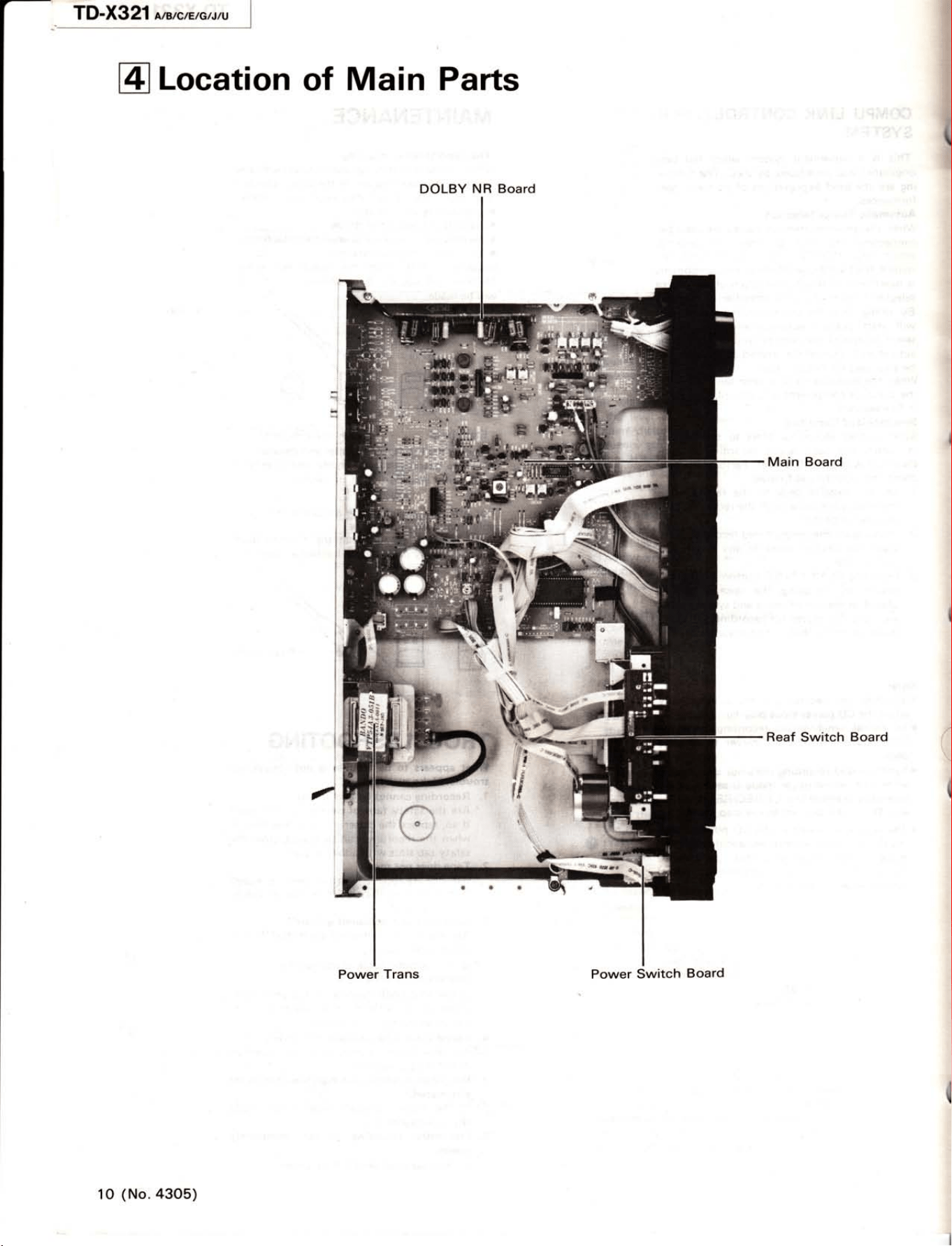
WLocation
of
Main Parts
Reaf
Switch
Board
I
(
DOLBY
NR
Board
1
0
(No.
4305)
TD-X321
en,e,e,au,u
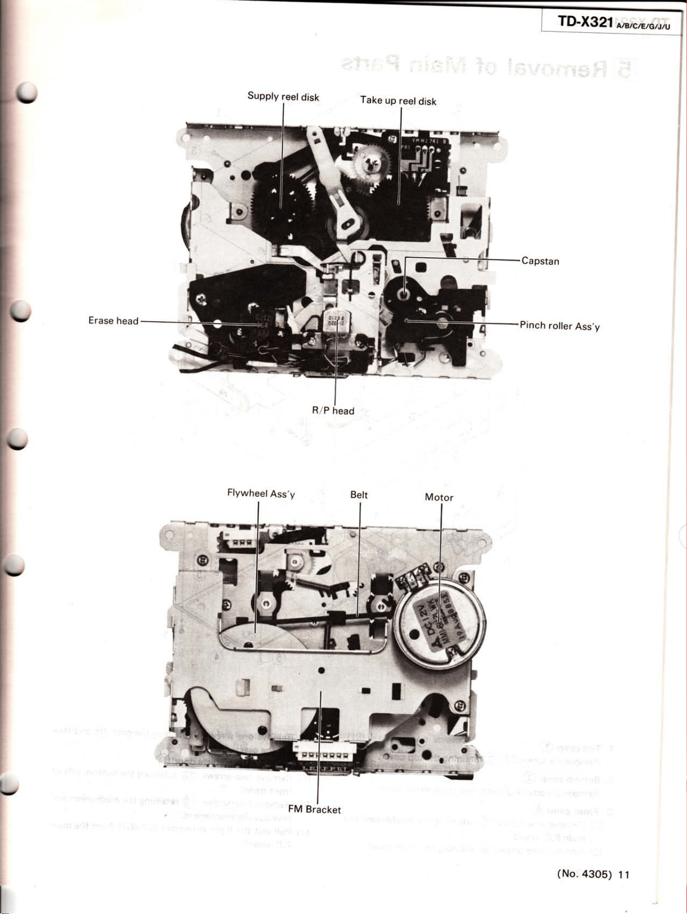
Supply
reel
disk
ïake
up
reel
disk
M
-
ll
Capstan
Pinch
roller
Ass'y
T1"il
r
H
ffi
I
"r l
-,
Erase
head
Motor
R/P
head
FlywheelAss'y
FM
Bracket
(No.
a3O5)
11
TD-)«}fi
;ia,ie*,*ïl)
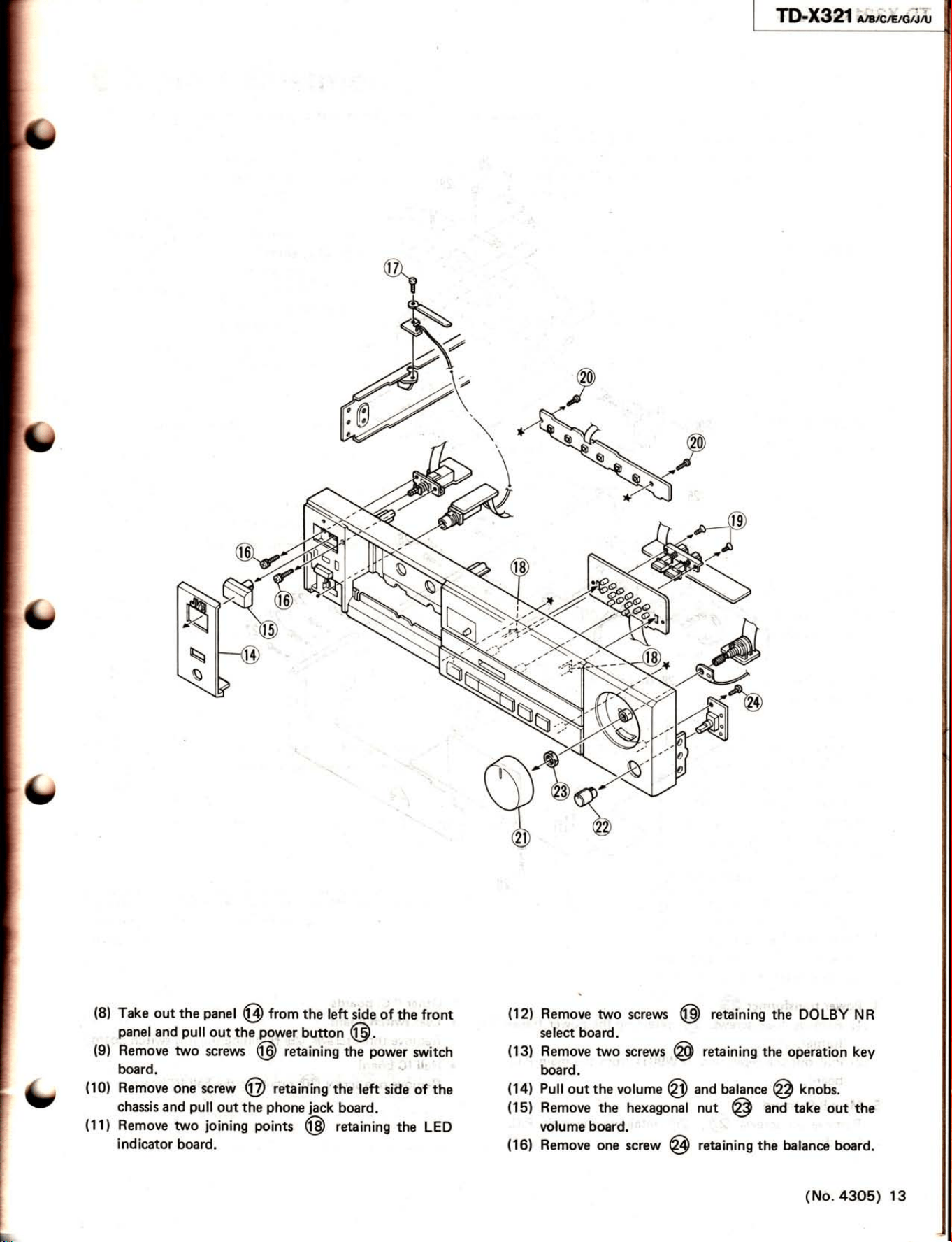
(8)
Take out
the
panet
@
trom
the left
iiae
of
the
front
panel.and putl
out thó
q.oWer button
@.
:
(9)
Remóve two
screws
@
retaining
thà
power
switch
(12)
Remove
two
screws
@
retaining
tfre OCiLÉV
ryn
se[ect
board.
(13)
Remove two
screy§
@
retaining
the
opération key
board.
(16)
Remove
one
screw
@
retaining the balance
board.
board.
(10)
Remove
one screw
@
reUíníng
the
left
side of
the
chassis
and
pull
out the
phone
jack
board.
(11)
Remove
two
joining
points
@
retaining
the
LED
indicator
board.
(14)
Pull
out the
volume
@
(15)
Remove the
hexagona!
nolume
board.
and balanc"
@
knobs.
nut
@
.Àí,rk, out the
(No.
a3o5)
13
il)"Xgeí
ÍftëaÉ,rillÀ
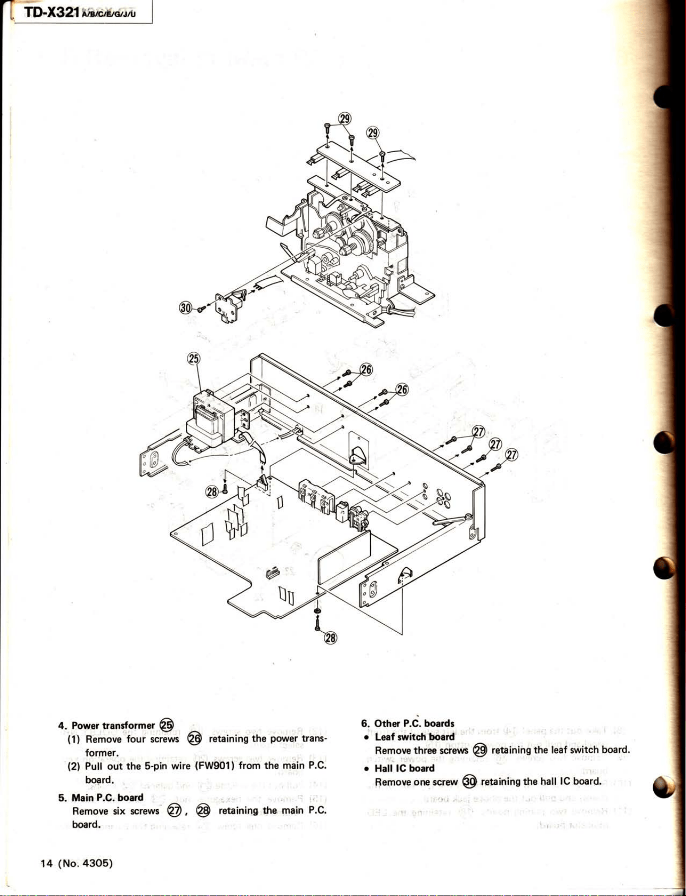
(1)
Remove
four
t"rí**
@
retaining
the
power
trans-
former.
(2)
Pull out
the S-pin wire
(FW901)
from
the
main
P.C.
5.
Main
P.C.
bord
Remove six
screws
@,
@
retaining
the' main
P.C.
board.
14
(No.
4305)
6. Other
P.C. boards
o
Leaf switc{r
board
Remove
three
scre\À6
@
r-etainiirg
the leaf switch
board.
o
Hall
lG board
I
1'
,
Semove
one screw
@
reuining
the
hall
lC board.
r
TD-X
g21
M,llcatctrtu
tr
Main Adiustments
1. Equipment and measuring
instÍumonB used for adjuíments
1) Electronic voltmeteÍ
6) Resistor 600 Q
(for
íttenuator
matching)
2)Audio
frequency oscillator
TlDistonion
meter
(bendpar§
filter)
(range:
50-20
kHz
and
outpui
O
dB dith impedance oÍ 600
Ol 8)Wow
flutter meter
3)Attenuator
(impedance:
600
Q)
9)
FÍequency
counteÍ
4)Standard tape.Íor R EC/PB
Maxell UDI
(T99)
-
Normal{SF)
tape
r
Pow.Í rurcG
TDKSA
-
Chmma
(SA)
tap8
-
or equivalent
Set
the line.voltage selector
switó to
240
V/230 V/
JVCME
,
-Metal
tape
:
22OVl127Vl12OVl110V
according to
your
local
5)
Reference tape for
playback
(JVC
TestTape)
voltage.
VTT7l2
(for
tape
speed,
r.yow Íluttèr adi.)
AC 2/O V, 50/60
Hz
(TD-X321A/B)
VTT724
(for
playback
levell ,
AC 220 V, 50/60 Hz
(TD-X321
E/c)
VTT739
(for
playback
Írequency response)
AC t2O
V,60 Hz
(TD-X32IC/J)
vrr703L
(
10
kHz)
(for
head azimuth 8di.)
Ac 2§v
1127
v
t110
v, 50/60
Hz
(Ttlx321U)
2.
Mechanism
adjustment
procedure
o
Notice:
O
dBs
=
O.775
(V)
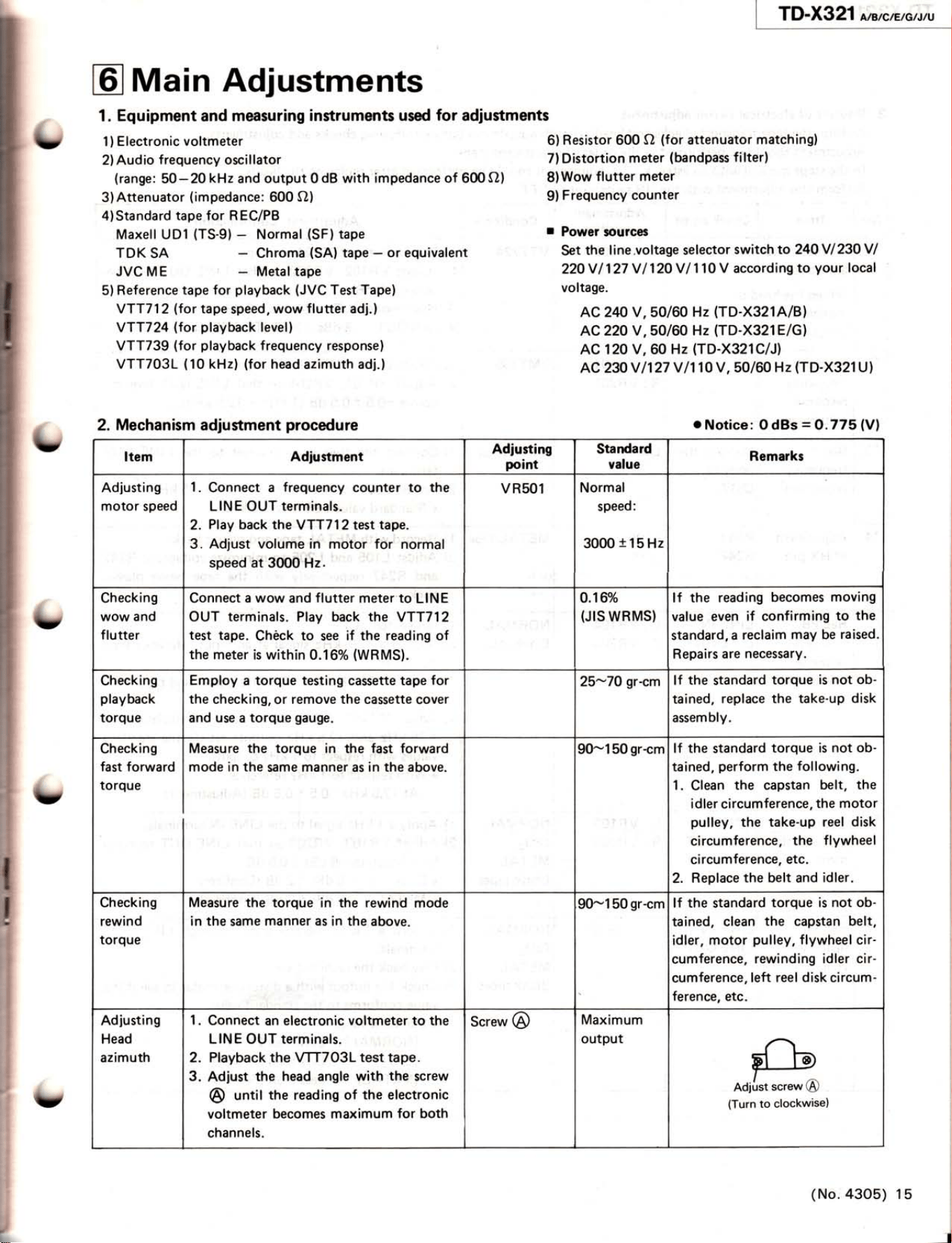
Item
Adiustment
Adiusting
point
Standard
value
Remarks
Adlusting
motor speed
1.
Connect a
frequency
counter to
the
LINE OUT
terminals.
2.
Play
back the
VTT712 test
tape.
3.
Adjust volume in
motor for
norma!
speed at
3fi)0 Hz.
V RsO1
Normal
speed:
3000
t
15
Hz
Checking
wow and
f lutter
Connect a wow and flutter meterto
LINE
OUT
terminals.
Play back the
VTT712
test tape.
Chèck
to
see if
the reading
of
the
meter
is within
O.16yo
(WRMS).
0.16%
(JIS
WRMS}
lf the reading
becomes
moving
value even
if confirming
to
the
standard,
a
reclaim
may be raised.
Repairs
are
necessary.
Checking
playback
torque
Employ
a torque
testing
cassette tape
for
the
checking, or remove
the
casette cover
and use a torque
gauge.
25-7O
gr-cm
lf
the
standard
torque is
not ob-
tained,
replace
the take-up
disk
assembly.
Checking
fast forward
torque
Measure
the torque
in the
fast
forward
mode in
the
same manner as in the above.
90-150
gr-cm
lf the
standard
torque is
not ob-
tained,
perform
the
following.
1.
Clean
the capstan
belt, the
idler
circumference,
the motor
pulley,
the take-up reel
disk
circumference,
the
flywheel
circumference,
etc.
2.
Replace
the belt
and
idler.
Checking
rewind
torque
Measure the torque
in
the
rewind mode
in the
same
manner as
in
the
above.
90-150
gr-cm lf the
standard
torque is not ob-
tained, clean
the
capstan
belt,
idler, motor
pulley,
flywheel cir-
cumference,
rewinding idter
cir-
cumference,
left reel
disk
circum-
ference, etc.
Adiusting
Head
azimuth
1.
Connect
an
electronic voltmeter to the
LINE
OUT
terminals.
2. Playback the
VTTTO3L
test tape.
3.
Adiust
the head angle
with
the
screw
@
until
the
reading
of
the
electronic
voltmeter becomes maximum
for both
channels.
Screw
@
Maximum
output
(No.43O5)
15
r
TD-X321
NarcEto^tru
i
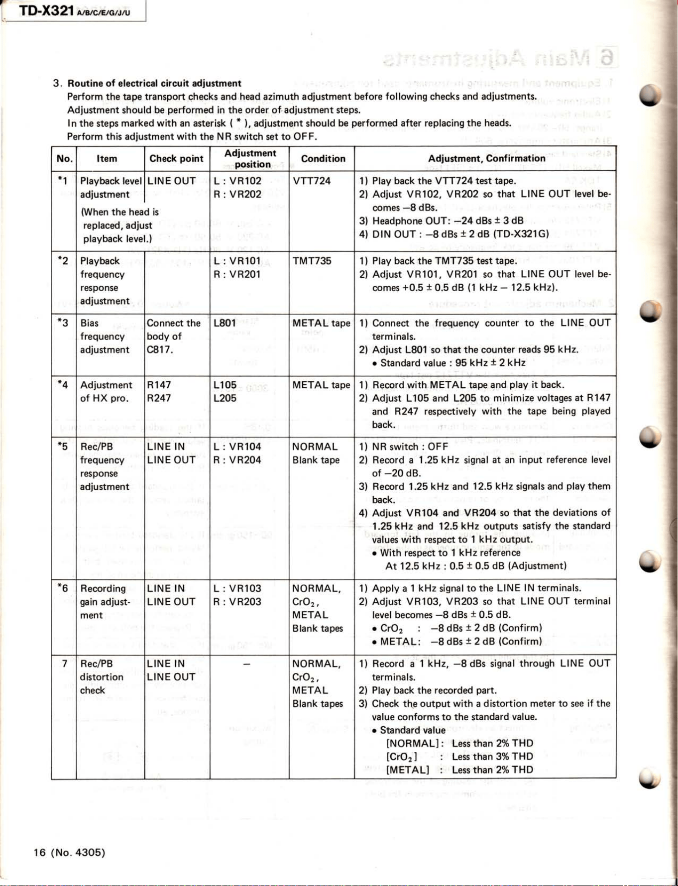
3. Routine oÍ electrical circuit adiustment
:
Perform
the tape
transport
checks and head azimuth adiustment
before
following
checks and adjustments.
Adjustment
should
be
per:formed
in the
order
of-adjustment steps.
ln
the steps
marked with an
asterisk
(
*
),
adiustment should
be
performed
after replacing
the
heads.
Perform this adjustment
with
the N R
switch set
to OF
F.
No. Item Check
point
Adiustment
position
Condition
Adjustment,
Conf
irmation
*1
Playback
level
I
LIN
E
OUT
I
adiustment
l
(When
the head is
replaced, adjust
playback
level.)
L:
VR102
R : VR2O2
vTT724 1)
Plarr back
the vTT724
te§t tape.
2) Adjust VR102,
VR202
so
that LINE
OUT
level
be-
comes
-8
dBs.
3) Headphone
OUT:
-24
dBs
t
3
dB
4) DIN
OUT
:
-8
dBs
t2
dB
(TD-X321G)
*2
Playback
frequency
response
adjustment
L: VR101
R
:
VR201
TMT735 1
)
Play back,the
TMT735
test
tape.
2) Adjust VR101, VR201 so
that LINE OUT level
be-
comes
+0.5
+
0.5
dB
(1
kHz
-
12.5
kHz).
*3
Bias
frequency
adiustment
Connect the
body
of
c81
7.
L801 METAL tape 1) Connect the
frequenqy counter
to the LINE
OUT
terminals.
2)
Adjust
L801
so
that the counter
reads 95
kHz.
r
Standard
value
:
95
kHz
l
2kHz
*4
Adjustment
of HX
pro.
Rl47
R247
L105
L205
METAL tape
1
)
Record
with,
METAL tape
and
play
it
back.
2) Adiust Ll05 and L205 to
minimize
voltages at
R147
and
R247 respectively
with
the
tape being
played
back.
*5
Rec/PB
frequency
response
adjustment
LINE IN
LINE
OUT
L
: VR104
R : VR204
NORMAL
Blank tape
1)
NR
switch: OFF
2) Record a 1.25
kHz
signa!
at an input
reference level
of
-20
dB.
3)
Record
1.25kHz
and
12.5kHz
signals
and
play
them
back.
4)
Adjust VR104 and
VR204
so
that
the
deviations of
1.25
kHz
and 12.5kHz
outputs satisfy
the standard
values
with respect to 1
kHz output.
o
With respect to 1
kHz
reference
At 12.5
kHz
:
0.5
t
0.5
dB
(Adjustment)
*^
o
Recording
gain
adjust-
ment
LINE IN
LINE OUT
L
: VR103
R : VR203
NORMAL,
CrO2,
METAL
Blank tapes
1) Apply
a
1
kHz
signal
to
the LINE
lN terminals.
2) Adjust VR103,
VR203
so
that LINE OUT
terminal
level
becomes
-8
dBs
t
0.5
dB.
o
CrO2 :
-B
dBs
+
2
dB
(Confirm)
o
METAL:
-8
dBs
t
2 dB
(Confirm)
7
Rec/PB
distortion
check
LINE
IN
LINE OUT
NORMAL,
CrO2,
METAL
Blank tapes
1) Record a
1 kHz,
-8dBs
signal
through LINE OUT
terminals.
2l
PlaV back the recorded
part.
3) Check
thp output
with
a
distortion meter to see if the
value
conforms to the standard
value.
o
Standard
value
INORMALI
: Less than 2%THD
lCr0z
I
:
Les
than 3%
THD
IMETALI
: Less than2o/oTHD
1 6
(No.
4305)
-
Adjustment,
Confirmation
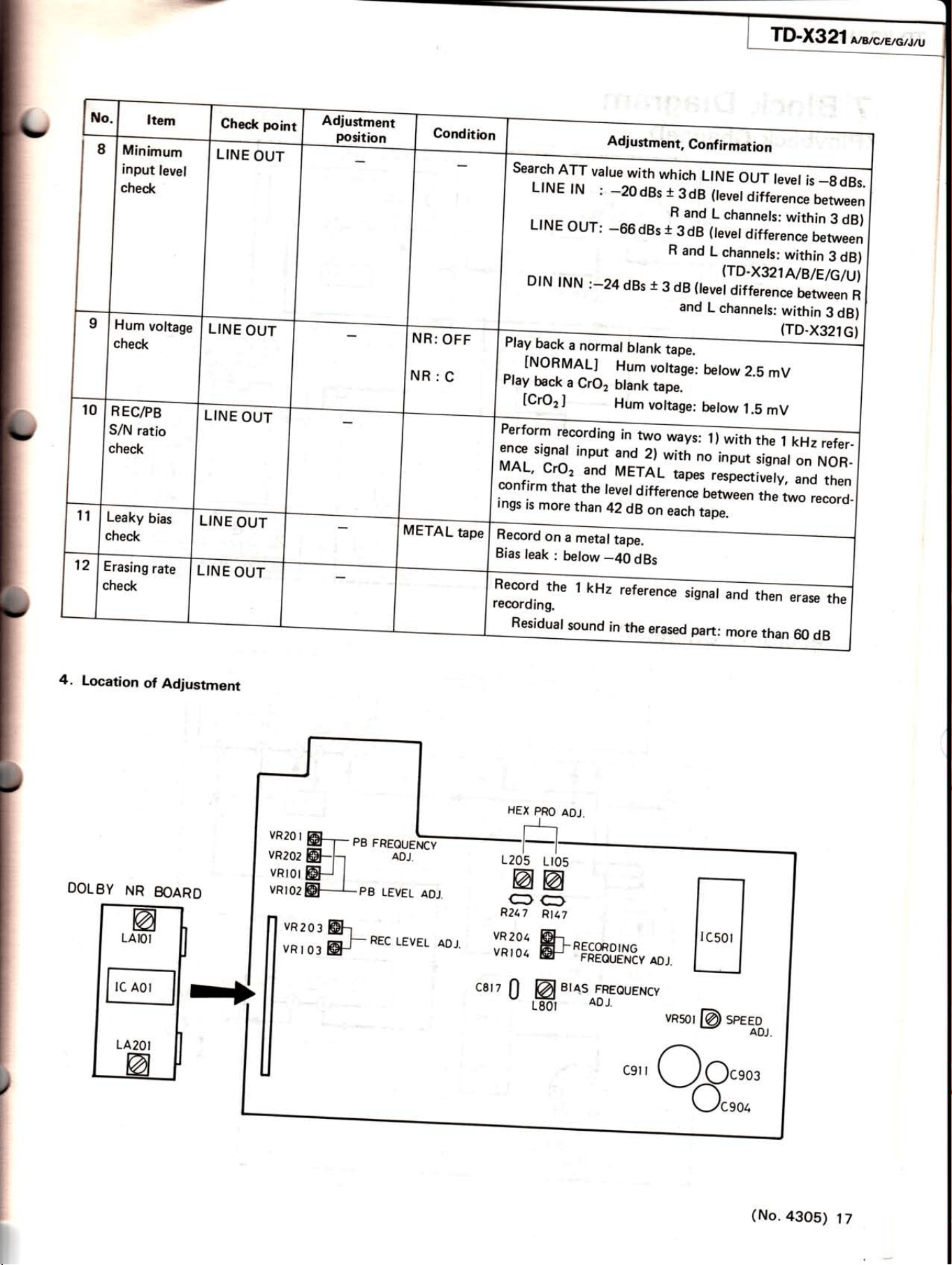
Minimum
input
levet
check
LINE
OUT
(TD-X321G)
search
ATT
varue
with
whích
uNm
LINE
lN
:
-2OdBs
t
3dB
(tevel
difference
between
Lr
N E
our:
-66
dBs
-t
H
hïliïïïl;ï.,Ï,,1*::l
R
and
L
channets:
withín
3
dB)
DrN
rNN
:-24dBs
r
3
dB,evell?;àllifr;fl:íï
and
L
channets:
within
3
dB)
LINE
OUT
NR:
OFF
NR:C
Play
back
a
normat
Ut.nÈEpf-
-
INORMAL]
Hum
voltage:
betow
2.8
mV
Play
back
a
CrO2
blank
tape.-
[CrO,
]
Hr,
,oit.ge:
betow
l.E
mV
R
EC/PB
S/N
ratio
check
LINE
OUT
Perform
recording
i,
::ff
t,::1
ínou1
?:!_2t
with
no
input
sisnat
on
NoR-
MAL,
Cro2
and
METAL
tapes
röil:il,
il'ïi
confirm
that
the
reverdifference
between
the
two
record-
ings
is
more
than
4ZdB
on
,..t,
,.0r.
Record
on
a
metal
tape.
Bias
leak
:
below
-40
dBs
LINE
OUT
Record
the
I
kHz
referen
recording.
Residual
sound
in
the
erased
part:
more
than
60
dB
4.
Location
of
Adjustment
DOLBY
NR
BOARD
VR
2Ol,
vRt04
carz
I
RECORDING
FREOUENCY
ADJ.
uaw@
spEqo_
ce
oEï:,
HEX
PRO
ADJ.
Lt05
@
C}
Rt17
&
'B'
t'^to[TouENcY
1205
@
cf,
Rzq7
(No.
43OS)
lt
TI»X32í
rfiircax*rru
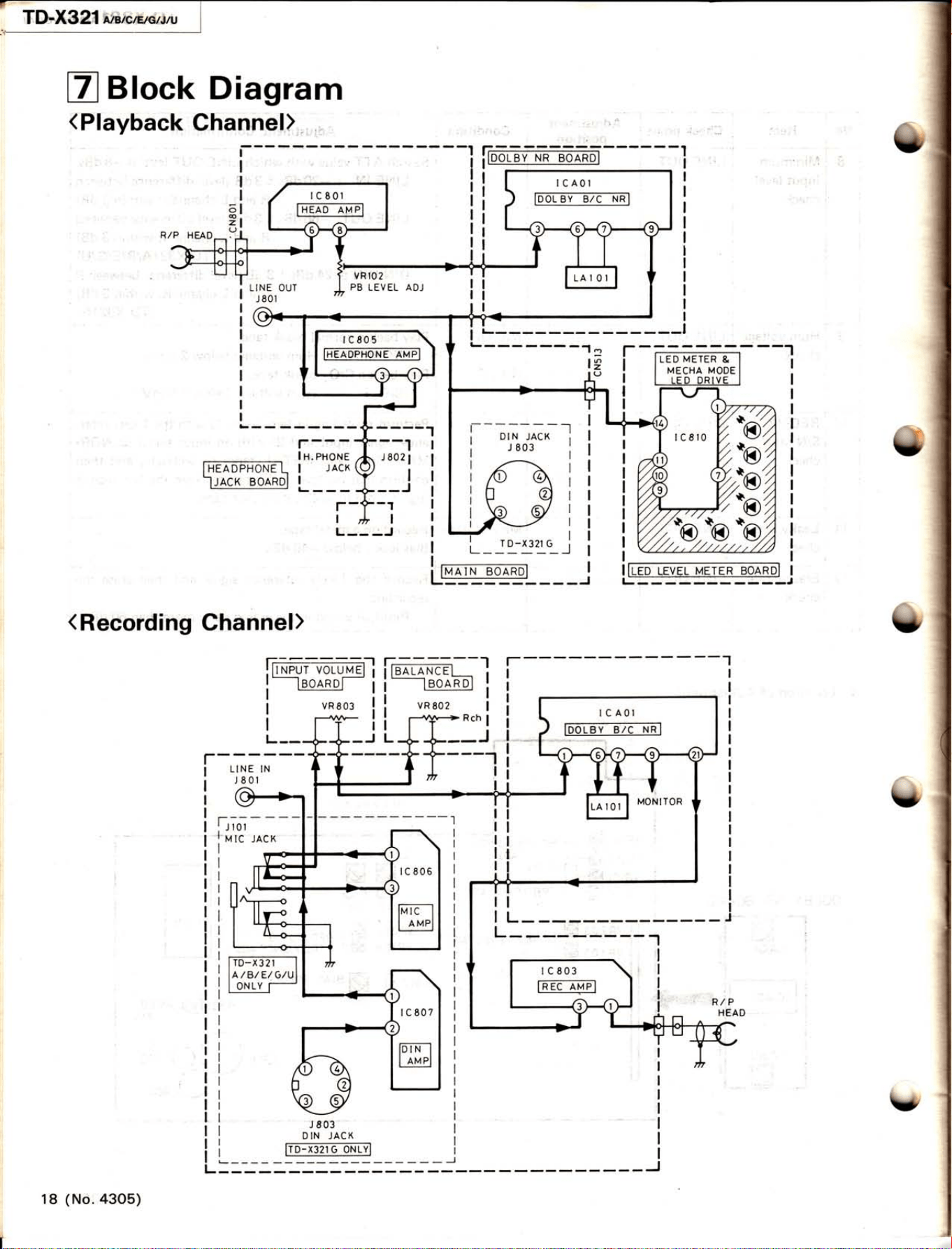
ZBlock
Diagram
(
Playback
Channel),,,,,-
í?ï-
-
-r--1
L_J1-x31G_J
; fMArN Bo-oARDl
l--
lffit
L---,
(
Recording
Chànnel)
l--------|---_ïÍ_
lLtNp.ur
vor-uuE
;
;mtl.Ne-+_ I i
I
lBoARDl
!l
lBoARDl
i
I
----1
I
ili
I L-
---i
b''ó"@
1
8
(No.
4305)
TD-X321 a'rcrcrer.tru
I
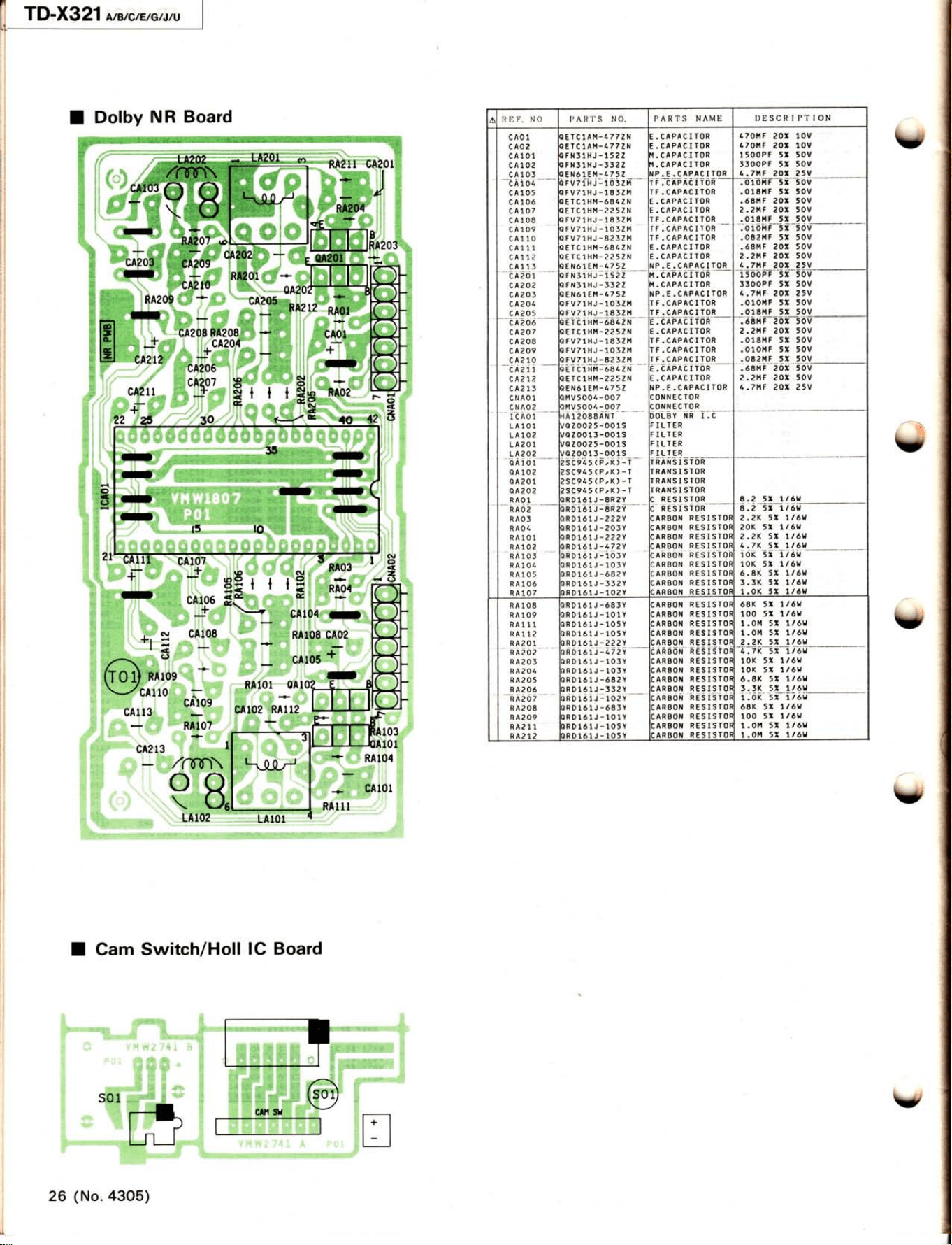
Dolby
NR
Board
RET'. NO I,'AR1'S NO.
PARTS NAME
DESCRIPTION
c
A01
cA02
CA1O1
c4102
c4105
-
cÀioa--
c4105
cA10ó
c4107
c4108
cA1o9
c4110
c4111
cA71?
c4113
-óÀ2or
c A?02
cA203
c4204
cA205
-
ön206.-
c
A?o7
c4208
c4209
CA21O
-cÀarr
c4212
c4215
CNAOl
CNAO2
ICAOl
LATOl
LA1O2
LA2Ol
LA2O2
bÀiot
04102
0A201
a4202
RAOl
ETCIAt'l-4772N
ETClAM-4772N
FÍtl31HJ-1522
FN3lHJ-3322
ENó1Er.l-4752
rvTiiri-iöszm
FV71HJ-1832l'l
ETClHM-6E4ZN
ETClHM-2252N
FV71HJ-1832M
rilzrH.l-rószm
rv71HJ-8232M
ETCIHm-6842N
ETClH14-2252N
ENó1EÍrt-4752
rH:irii-t527
--
FN51HJ-3322
ENó1EÍ,1-l.752
FV71HJ-1032tl.|
FV71HJ-1852r.t
:.CAPACITOR
:.CAPACITOR
,,I
.CAPACITOR
,I
.CAPACITOR
{P.E.CAPACITOR
rF.eÀÉÀöÍÍöF-
TF.CAPACITOR
:.CAPACITOR
:.CAPACITOR
TF.CAPACITOR
i
r
. cÀpac I
roR
.---'
TF.CAPACITOR
:.CAPACIÏOR
:.CAPACITOR
!P. E. CAPACITOR
,i.
éÀFÀè iïon
-
'I
.CAPACITOR
{P.E.CAPACIÏOR
ÍF.CAPACITOR
TT.CAPACITOR
a. e
À?-Àe I
Í0n
-E.CAPACITOR
TF.CAPACITOR
TF.CAPACITOR
TF.CAPACITOR
í-eÀÉÀeiïöh
--
E.CAPACITOR
TP.E.CAPACITOR
CONNECTOR
coNNECT0R_____
)OLBY
NR
I.C
FILTER
FILTER
FILTER
FILÏER
70l,tF 20:10v
7ol,lF
2O:10V
500PF
51 50V
300PF 5X 50V
.7AF 20X 25V
o1ottF 5x 50v
o18tíF 5r 50V
óEr.íF
20Í 50V
. ?l,,lF
201 50v
o18ÍitF 5X 50V
010MF 5I
50V
082Í.lF 5:50V
68MF
202
50V
t.2MF 20Í 50V
,-7MF
20r 25V
50öÉF'5z50v
i300PF 5:50V
,.7tcr.
202 25V
O10l.lF 5z 50V
,o18MF 5:50V
ETClHÍ,,|-ó842N
EïC1HM-2252N
FV71HJ-183214
FV71HJ
-1032M
FV7lHJ-8232È1
ó8r,r
F
.zt'lF
018i.t
F
o1oilF
082Í.tF
20r 50v
20r 50v
5X 50V
5l 50v
5Z 50V
1EïC1HM-ó8/.ZN
tETClHl,l-2252N
)ENó1EM-/,752
tMV5004-007
)MV500/.-O07
rÀrzoaaÀNr
,/o20025-oo1s
/ozo013-o01s
/a20025-001s
/02o013-001s
2sci?s
(P;Ki-i-
2SC945(P,K)-T
2SC945(P,K)-T
2SC945(P,K)-Ï
TRDló1J-8R2Y
ó8M
F
.2l4F
-7t(F
202 50v
20t 50v
207 ?SV
RANS
I
STOR
RANSISTOR
RANSISTOR
RANS I STOR
RESISTOR
-
RÈSTSÍoí--
ARBON
RESISTO$
ARBON RESISTOX
ARBON RESISTOF
AgBoN
RESJSJo!
ARBON
RESIS-TOF
ARBON
RESISTOF
ARBON RESISÏOF
ARBON
RESISTOT
ARBON RESISTOT
E ,t 7t6u2
RAO2
RAO3
RAO/.
RA101
RA1O2
RA1O3
R
41 01.
R4105
RAlOó
RA1O7
RD1ó1J-8R2Y
RD1ó1J-222Y
RD1ó1J-203Y
RD1ó1J-222Y
RD1ó1J-472Y
riororl-iosv
RD161J-103Y
RD1ó1J-óB2Y
RD1ó1J-332Y
RD1ótJ-102Y
8.2
'/
lt6u
2-2R 51 llóU
20K
5X 1/óU
2.2K 5r tt6lJ
t,-7K
5t ïl6bt
ioK 3i 1rèu
-
10K 5Z 1/óW
ó.8K 5Í
1/óu
f-3K 5U 1/óU
1.0K 5l
1/61'
RA1O8
RA1O9
RA111
R4112
RA2O1
rRD161J-ó83Y
IRDló1J-101Y
lRDló1J-105Y
lRDló1J-105Y
IRDló1J-222Y
rnóioi-j-.c72V
-
)RD1ó1J-103Y
rRDló1J-103Y
lRDló1J
-ó82Y
lRDló1J-332Y
rioràii-rozV
-'-
IRDló1J-ó83Y
)RD1ó1J-101Y
rRDló1J-105Y
IR01ó1J-105Y
;AR8OT{
RESISTOT
:ARBON
RESISTOI
:ARBON
RESISTOI
:ARBON
RES I STOI
:ARBON
RESISTOÍ
:ÀRó0N
n˧i§ioi
:ARBON RESISTOÍ
:ARBOÍtI
RESISTOÍ
:ARBOI{
RESISÏOÍ
:ARBOI{
RESISTOí
:nnÉox hÈ5iSioÍ
:ARBOt{
RESISTOI
:ARBON
RESISTOÍ
:ARBOÍ.I
RESISTOÍ
:ARBON RESISÍOÍ
ó8K 5Z 1/ólt
100
5t 1/ór,
1.or,t
5t 1/ór{
1.01{ 5u 1/ór,
2.2K 5Z ll6bt
RAzO2
RA2O5
RA20/.
RA2O5
RA2Oó
lÀ2ö7
RA208
RA2O9
R4211
R4212
4.7K 5Z 7l6W
10K 5Z
1/ór{
10K 5r 1/óh'
ó.8K
5X 1
/ót
l.l[
s:-
1/É
1-
0K 5r 1/ó!l
6AK 5Z 7t6U
100
5u 1/óu
1 .01,1 5I 1
/ótl
1.0r.í
5X 1/6h,
ö
*Í
2
il.l
t\
;|il i
Est i
;sl
ë1
i€}
ii7!)
.i)t
#
b
t#
\)t
#t
)
íÉ,
§r
,r,{'
ri.i i'
i!:
L
v
Y
Y
Y
#öÏ?"
l-
ii:
.-
Li;:'i4,1 .,k
N
(9
Ë,
2
(J
cA213
à-i
t,,;i,61^nO,
:
i::: i;a .,
Ëilil07
.!::.
1ffi
0i1,
V;rÈr
103
loI
.!.'i'o'
-
'..c;'i:ë101
RÀIII
LAIUA
I
Cam Switch/Holl
IC
Board
26
(No.4305)
v
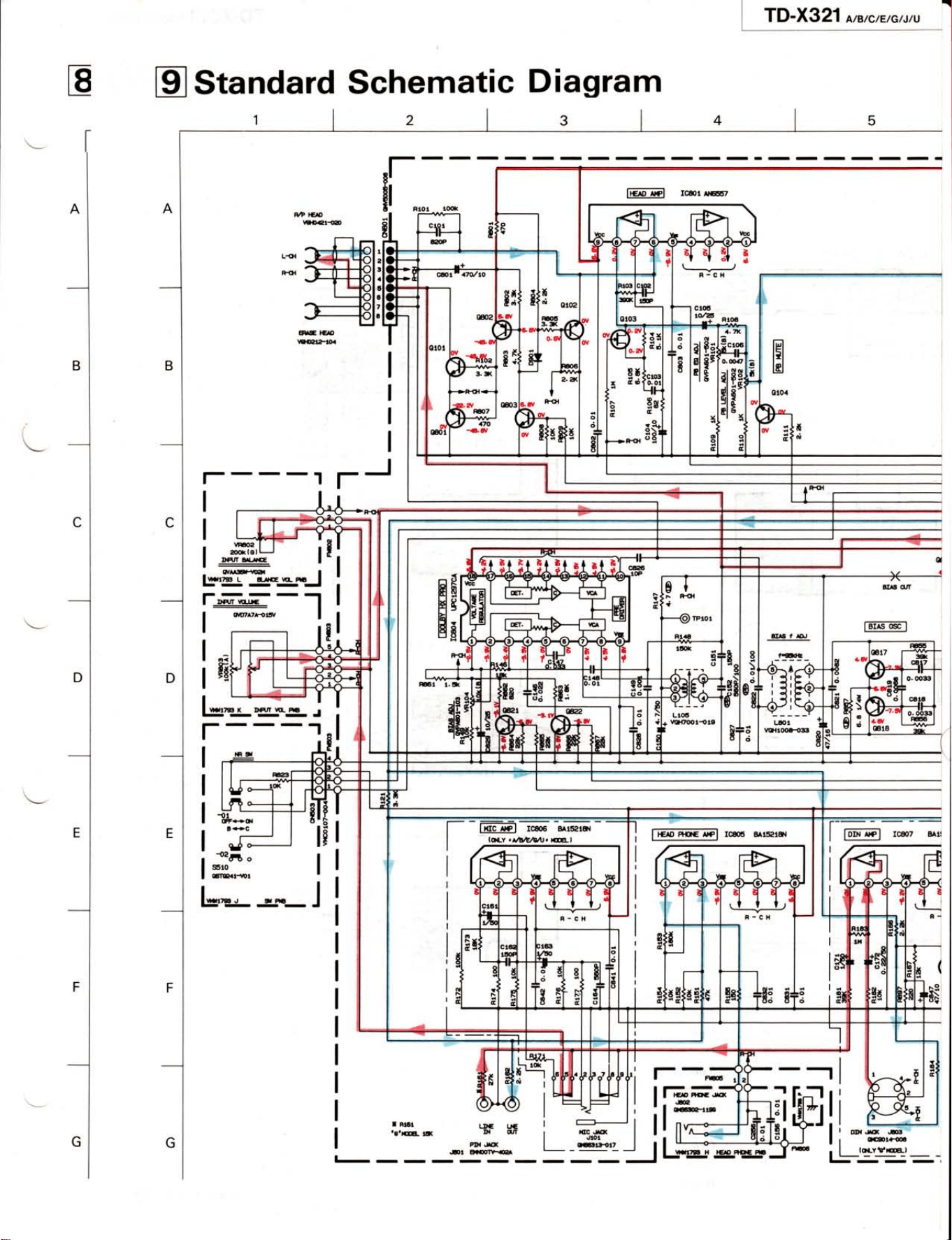
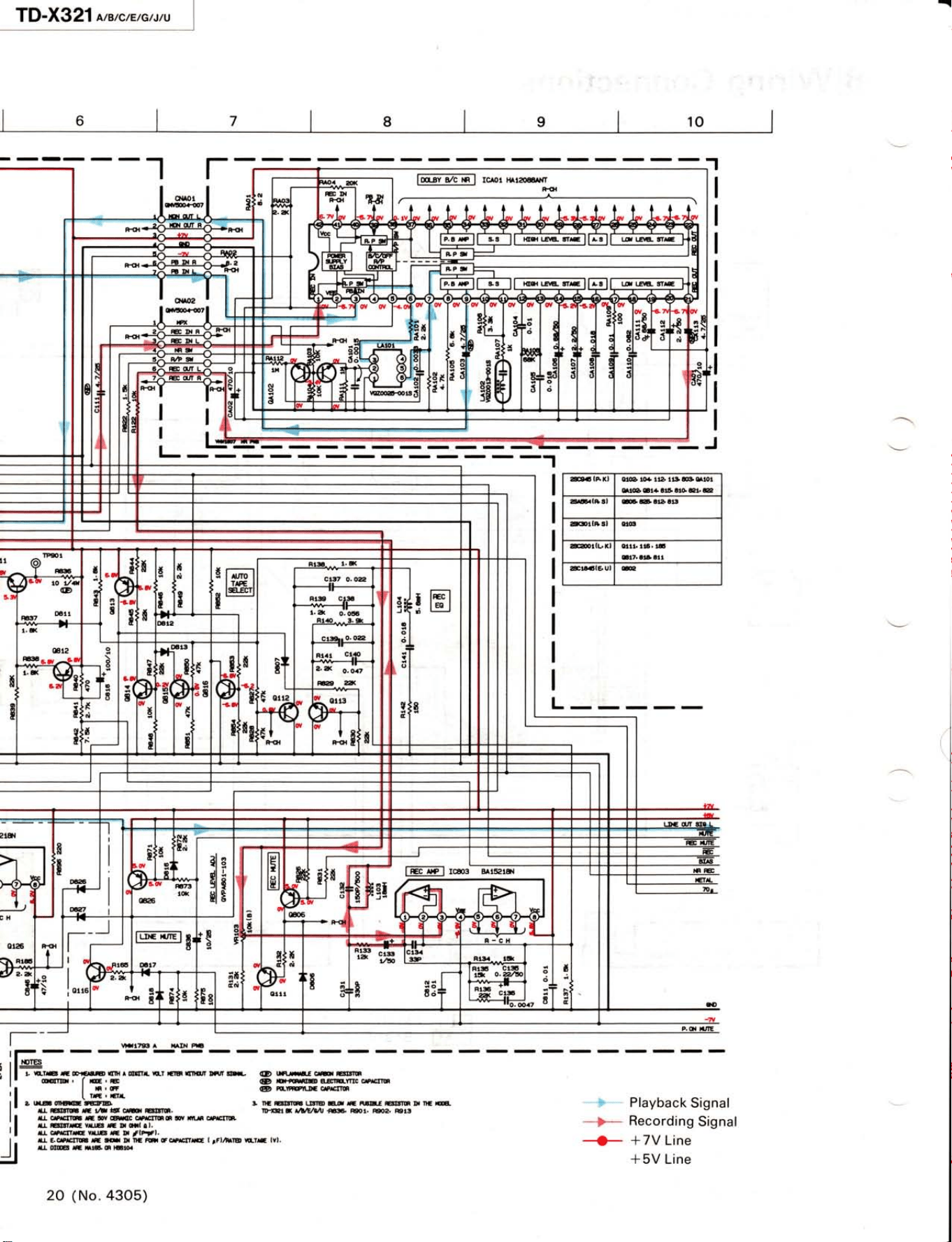
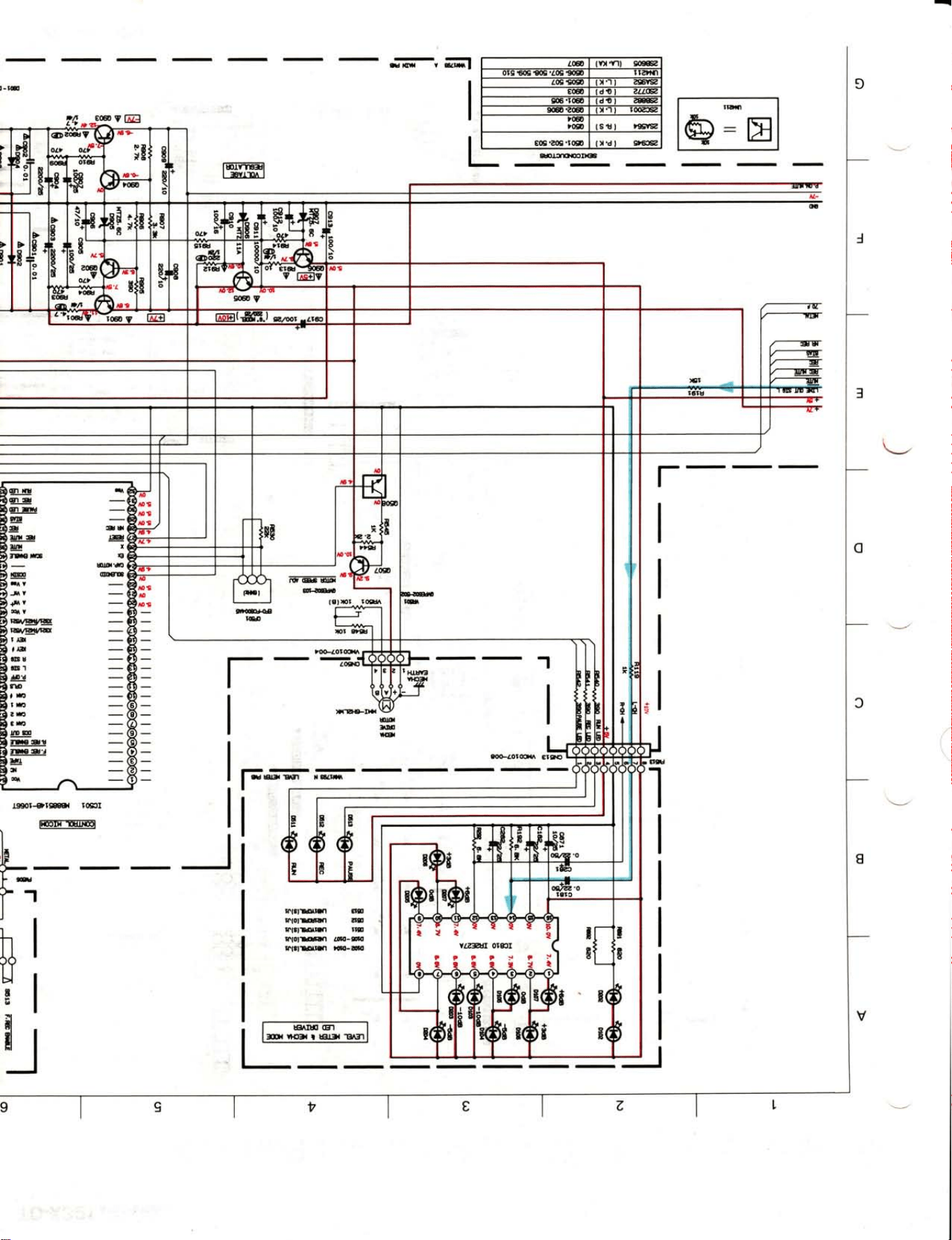
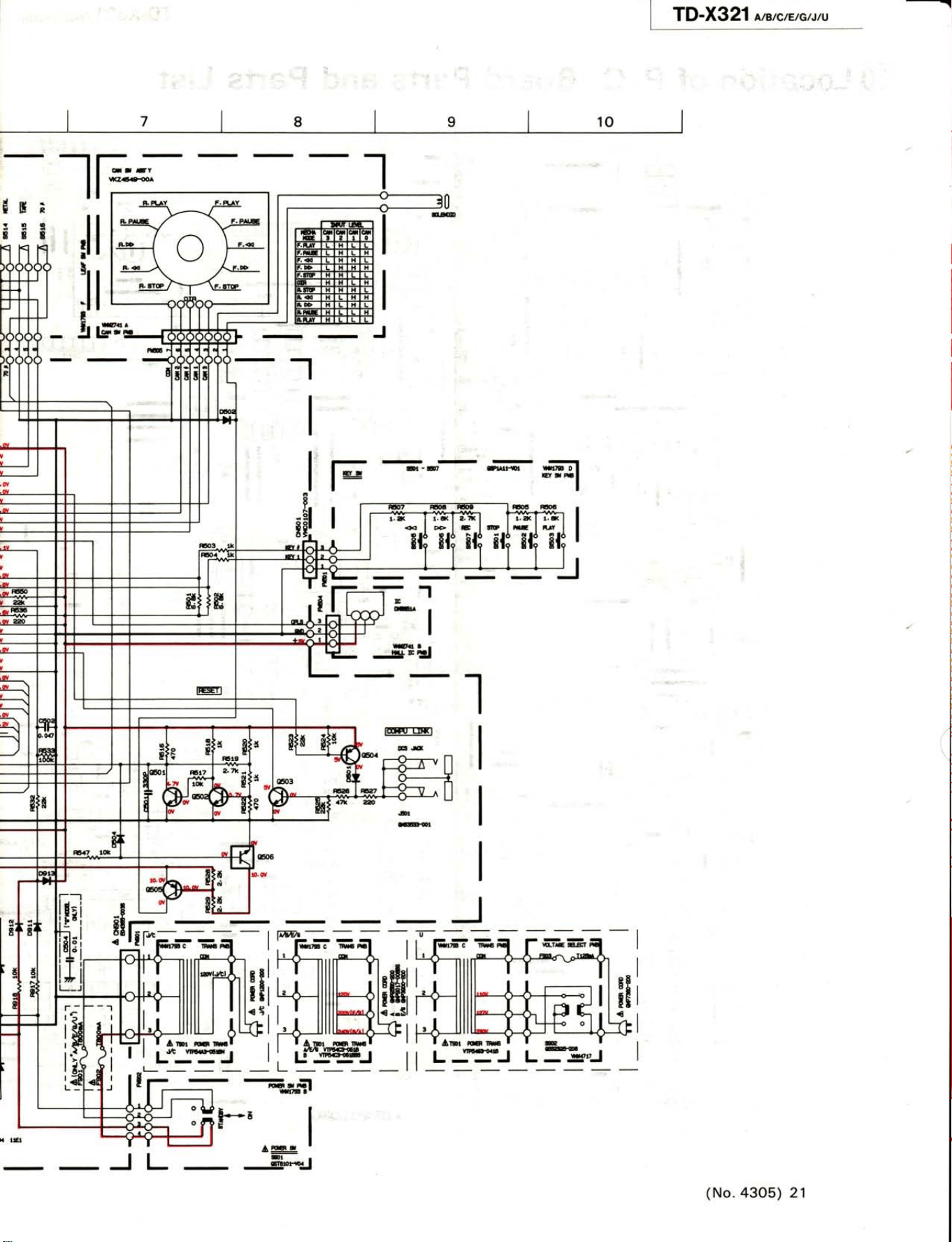
g
Standard
Schematic
Diagram
n-
Ël r
]
ro-x
g21
A/B/c/E/c/r/u
r---J
rJ
tl
l&-
l'l
g'fu-J:
l..@--'l
I
or,,^7t{rry
I
ficAp
ArPl
root
Arerrr
---
lr-
íF }G5
vloart{D
ArE
l€ro
IICUHOT
H.
vma
{261
o
s§r0
6IEatiDt
EAI
q'T
tffiEl
L*;Ër--.i
r----I
{t
CF€O'
l€C
@
IC&7
EAil
t=r-*.-l
I
$ar
'e'!@-
ril
I.DC IJC
DI C'IÍ
PD{ .IO(
.Dr
oaEnrea
lE,ffil
rcffi BArpre{
l---
a(c.ro(
Jtoi
oGiilt
---
I
rconu,c.s
TD-X321
a,rcErcruu
lol I
,o
I
I
zI'GíAXI
etGD to+ lla lul
an stot
nl@6t4trÉatoel.e
z!aË.lB!l
GEtàat!
alcDrlB!l
otG
&DrlL'rl oitt.
rtl.
lË
!t7. trl art
&!!.61Éul @
fo.ar,
a/c
inl
rc^or HArarelr{Í
lEFl
rms-- BArEF
'-s-
-
Playback
Signal
*p*
Recording
Signal
+
*7V Line
*5V Line
2o
(No.4305)
TD-X321
o,r,c,.,o,r,u
F90l
Í--:r
tt-tl
I'- )tcr I
F2
f---:*t
Il--tI
I
*J/L4
|
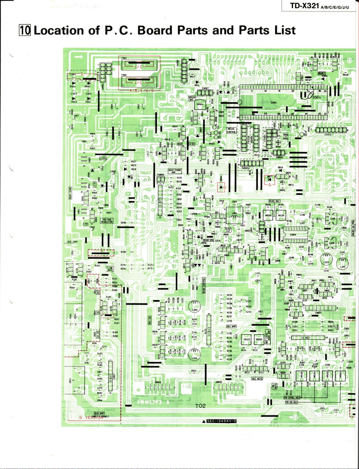
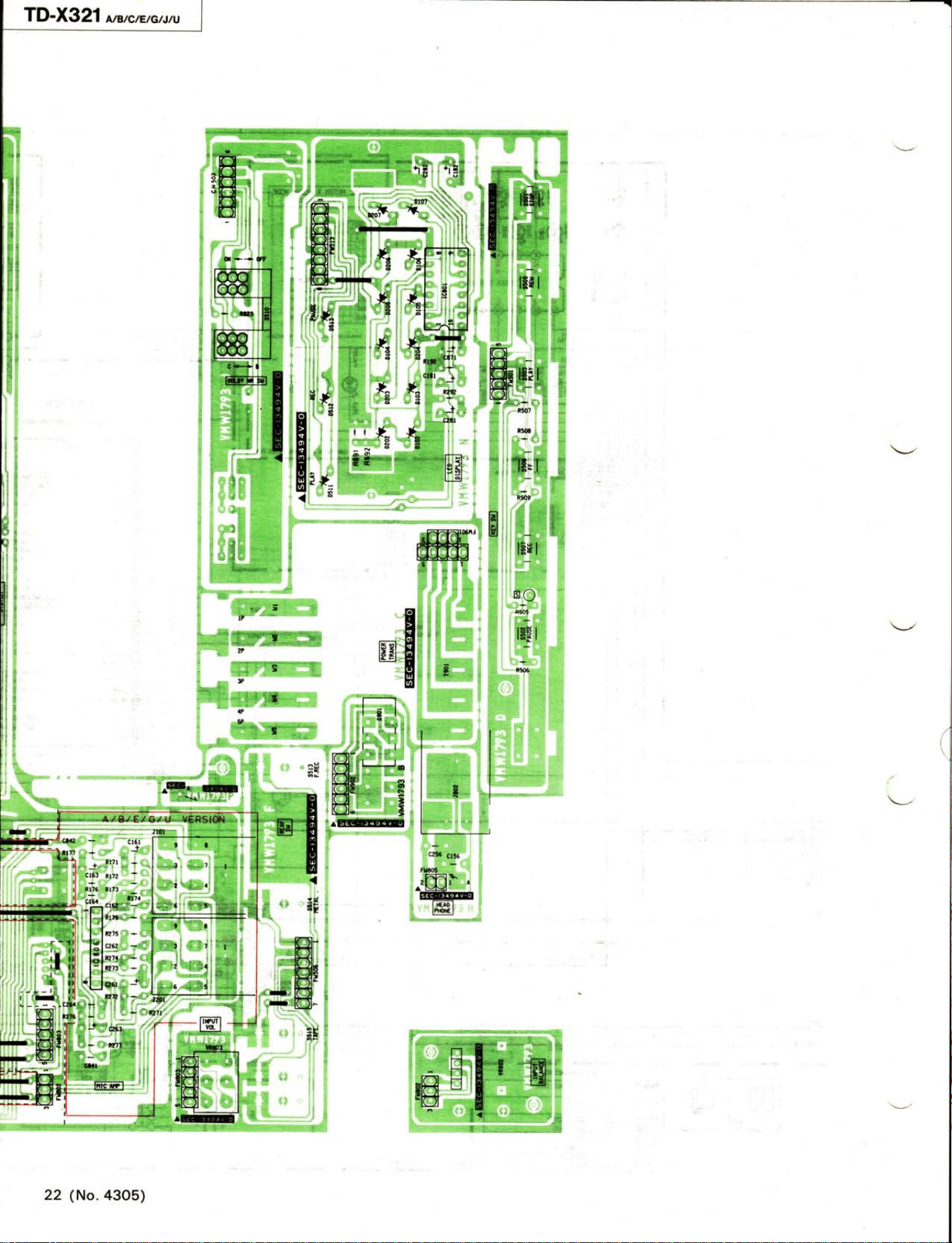
rc
Location
of
P.
C.
Board
Parts
and
Parts List
ïa2
eEEI@F
R19r
R?91
/6-\
/\
\sel
RUz
c24t
ct4l
Rl42
/ffi\
()
\s/
RY
R830
r-1o
L-l
al ll:l:l:l=
;r
.ll
R828
-
--o
tt
H
t I t!let!le
iLl
E
I
-
r
L-'l
.
20
I l7í,"^: ,"
c90í)
+
,csrac(
I
ll
E
[--t
TD-X321
*ercrE
e^tru
(
22
(No.4305)
rr
--8(E0
v
ÍEl
-
* [tx
v
Earn
I
I
IEFE-I
I *rrrr
I
.I
I
)xEll]ar
*t x tlaltll
ÍírÍ3lBraÍl §E
ríot.wr a5
s.(8lE§aÍr
llE
ÍríoluÍ't t§at-fr
g.ítlB§aíl
rilo-ato
&roa
xlr
tlt*
aoÈtol6at^
Cr5r5
J=r,,,-
t_
-
I tgllÍqt t
I lp,
nrrrr
r
terer e,rrrl
f
ï
t
I-*'
rï
r,l
ït
L
l.m
íV)tt'll 90*
or9 €i05 €o5
.Los
€o5
rrztÍrÍl
2,09.909 )t.-ll ?9618
EGD
SG'IGO ar?
@?@
x.r
I
IOGE
,q,l,
r00
s.r!,
I
,slsz
goe.?09.rm
x'd
I
g'.tEZ
E!.UIIlEI}GÉ
roqr
E!_g
a]!E
tD
ilxa
I=!
u!x
;Írt€ rfi:
*l
Elra'#3
E
(alsE
3r
-rl
Y
+lA
v
ar
i.Ei/-ryTg.
w,@t/w
r
li!
,Lil
SU
G1
!qí
rE
,m
rm
z t;,
3l}t
lrpg
JE€AÈ
l!!9-gl
tl
lll
q
TD-X
g21
,,,Brc,'tctrtu
10
I
rmm I
TEITIFITIFI I
IEiÍFÏIÏFÏiÏil I
leElLlHlLlHl
I
lË.-TETrrÍril
It#lhl'Sl*ltl r
E--TFTFT!Tfl
I
lrrE txtHlHtLl t
E+ffiHl I
lrx-t H I L I L I r{ I
-
IEffiÏFÏiTCTil
-J
-l
-
-
a
t
-.
-r-8,
t:
rm oI
rtrrul
-
tun{u
IJ
.I
I
U
-1
E
y'-^
rEa
JD
ir-
itT
I
Ímr'wt
EI
(No.
4305) 21
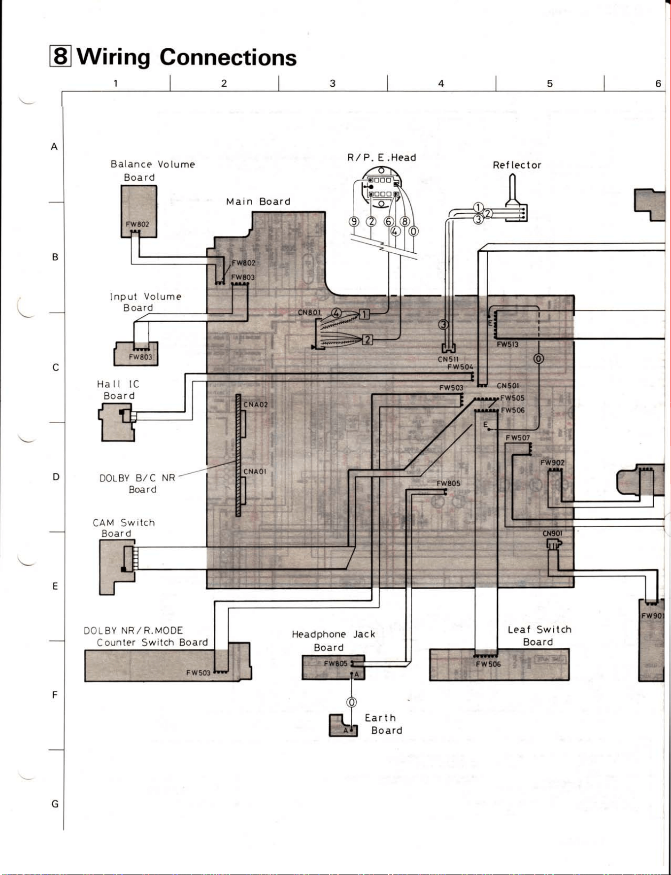
trWiring
Connections
Balance
Volume
Boa rd
Main Board
lnput
Volume
B
oard
Ha tl lC
Board
DOLBY
B/ C
Board
CAM Sw
itch
Boar
d
DOLBY
NR/
R.MODE
Counter Switch
Board
NR
R/P.
Headphone
Jack
Board
Ref lector
Leaf
Switch
Board
Earth
Board
E .
Head
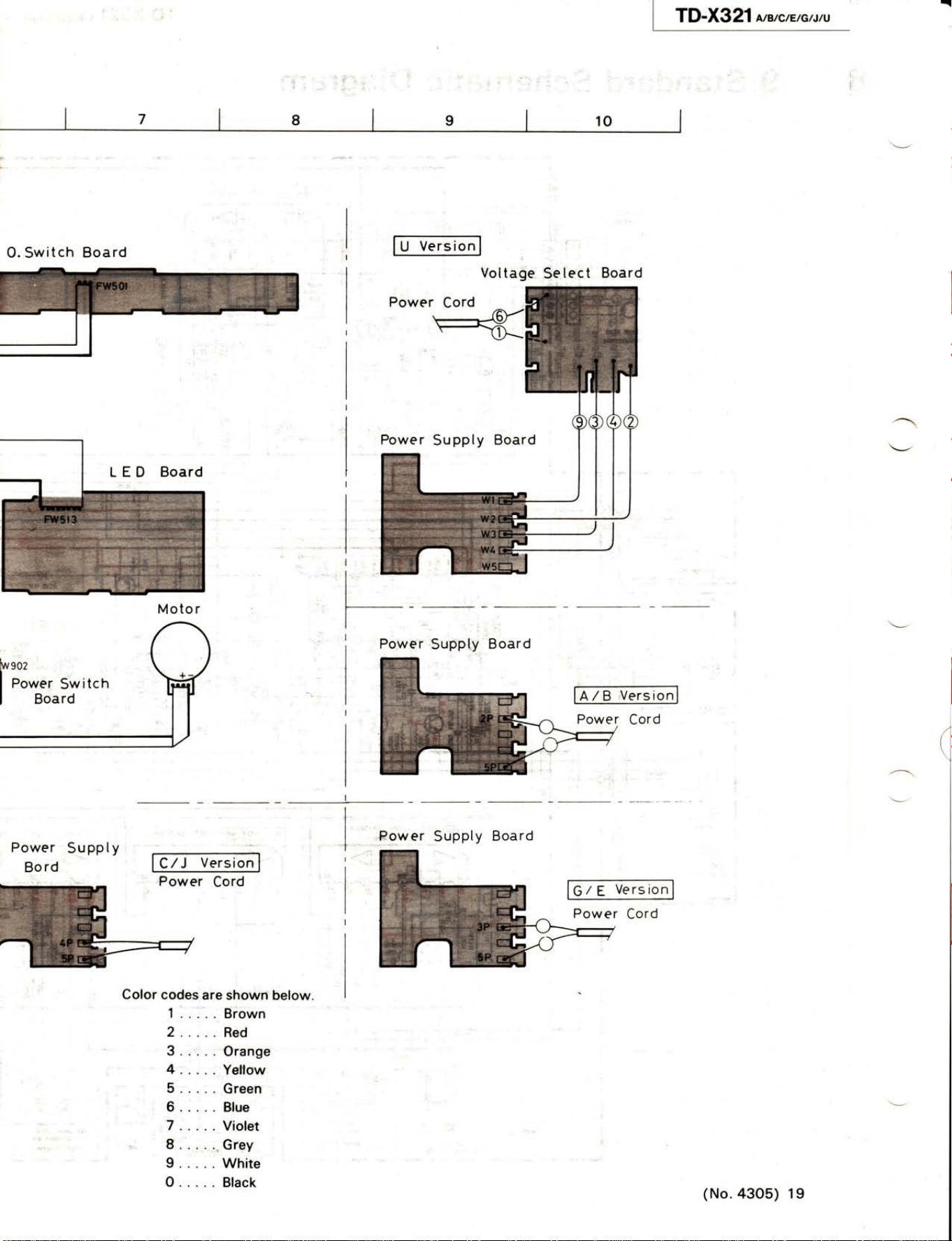
TD-X321
ln,rc'rcuru
I
ro
I
O.
Switch
Board
tu
versi".l
V
Power
Cord
Se
lect Board
Power
Supply
Board
lAlB-versto,il
Power
Cord
(
oltage
Moto
r
Power
Supply
Board
bvsoz
I
Po*.,
Sw
itch
I
Boaro
Power
Board
Power
Suppty
Bo
rd
Cord
Color
codes
are
shown below.
1.....Brown
2.....
Red
3.....Orange
4.....
Yellow
5.....Green
6..... Blue
7
.....
Violet
I
Grey
9.....White
O.....
Black
Suppty
Power
Cord
(No.
43o5) 1
I