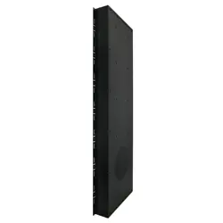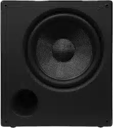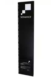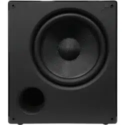
CABINET SUBWOOFER
INSTRUCTION MANUAL
MS10SUB

TABLE OF CONTENTS
Safety 2
Design and Features 4
Box Contents 4
Subwoofer Placement 4
Installing the Subwoofer
Flush to a Wall or Cabinet 4
Subwoofer Rear Panels 4
Subwoofer Connections 4
Audio Connections 5
Connection Examples 5
Subwoofer Adjustments 5
Specications 6
Warranty 7
1
IMPORTANT SAFETY INFORMATION
1. Read Instructions — All these safety and operating
instructions should be read before you operate the unit.
2. Retain Instructions — These safety and operating
instructions should be retained for future reference.
3. Heed Warnings — All warnings on the unit and in the
operating instructions should be adhered to.
4. Follow Instructions — All operating and use instructions
should be followed.
5. Water and Moisture — The unit should not be used near
water — for example, near a bathtub, washbowl, kitchen
sink, in a wet basement, or near a swimming pool, etc.
6. CartsandStands — The unit should be
used only with a cart or stand that is
recommended by the manufacturer.
A unit and cart combination should be
moved with care. Quick stops, excessive
force, and uneven surfaces may cause
the unit and cart combination to overturn.
7. CAUTION: To prevent electric shock, do not use the
subwoofer’s polarized plug with an extension cord,
receptacle, or other outlets unless the blades can be
fully inserted to prevent blade exposure.
8. Ventilation — The unit should be situated so that its
location or position does not interfere with its proper
ventilation. For example, the unit should not be placed in a
built-in installation, such as a bookcase or cabinet, that may
impedetheowofairoverthebackplate.
9. Heat — The unit should be situated away from heat
sources such as radiators, heat registers, stoves, or other
appliances (including other audio components) that
produce heat.
IMPORTANT: READ ALL OF THESE INSTRUCTIONS BEFORE YOU INSTALL
OR OPERATE YOUR SUBWOOFER AND SAVE THESE INSTRUCTIONS FOR
LATER USE.
The lightning flash with arrowhead
symbol, within an equilateral
triangle, is intended to alert the
user to the presence of uninsulated
dangerous voltage within the
product’s enclosure that may be of
sufficient magnitude to constitute a
risk of electric shock to persons.
The exclamation point within
an equilateral triangle is
intended to alert the user to the
presence of important operat-
ing and maintenance
(servicing) instructions in the
literature accompanying the
appliance.
10. Power Sources — The unit should be connected to a
power supply only of the type described in the operating
instructions or as marked on the unit.
11. Accessories and Attachments — Only use accessories
andattachmentsspeciedbythemanufacturer.
12. Grounding or Polarization — Precautions should be
taken so that the grounding or polarization means of the
unit is not defeated.
13. Power Cord Protection — Power cords should be routed
so that they are not likely to be walked on or pinched by
items placed upon or against them, paying particular
attention to cords at plugs, convenience receptacles, and
the point where they exit from the controller.
14. Cleaning — The unit should be cleaned only as
recommended by the manufacturer.
15. Non-Use Periods — The power cord of the unit should be
unplugged from the outlet when left unused for a long
period of time.
16.ObjectandLiquidEntry — Care should be taken so that
objects do not fall and liquids are not spilled into the
enclosure through openings.
17.DamageRequiringService — The unit should be
servicedbyqualiedservicepersonnelwhen:
• The power cord or the plug has been damaged.
• Objects have fallen or liquid has been spilled into the unit.
• The unit has been exposed to rain.
• The unit does not appear to operate normally or exhibits
a marked change in performance.
• The unit has been dropped or the enclosure damaged.
18. Servicing — The user should not attempt to service the
unit beyond that described in the operating instructions.
Allotherservicingshouldbereferredtoqualied
service personnel.
This device complies with part 15 of the FCC Rules.
Operationissubjecttothefollowingtwoconditions:
(1) This device may not cause harmful interference
(2) This device must accept any interference received,
including interference that may cause
undesired operation.
InaccordancewiththeEuropeanUnionWEEE(WasteElectricalandElectronicEquipment)directiveeective
August 13, 2005, we would like to notify you that this product may contain regulated materials which upon
disposal, according to the WEEE directive, require special reuse and recycling processing. For this reason
Sonance has arranged with our distributors in European Union member nations to collect and recycle this
productatnocosttoyou.Tondyourlocaldistributorpleasecontactthedealerfromwhomyoupurchased
this product. Please note, only this product itself falls under the WEEE directive. When disposing of packaging
and other related shipping materials we encourage you to recycle these items through the normal channels.
SONANCE
SUBWOOFERS
Tested to comply
with FCC Standards for
homeoroceuseonly.
2
CONSIGNES DE SÉCURITÉ
IMPORTANTES
Cet appareil est conforme à la partie 15 des règles du FCC. L’utilisation est
assujettieauxdeuxconditionssuivantes:(1)cetappareilnedoitpascauser
d’interférence nuisible, et (2) cet appareil doit accepter l’interférence reçue,
notamment l’interférence qui peut causer un mauvais fonctionnement.
REMARQUE:cetéquipementaététestéetjugéconformeauxlimitesd’unappareil
numérique de Classe B, en vertu de la Section 15 du règlement de la FCC. Ces limites
sontconçuespouroriruneprotectionjugéeraisonnablecontrel’interférencenuisible
dans une installation résidentielle. Cet équipement génère des utilisations et peut
émettre une énergie radiofréquence et, s’il n’est pas installé et utilisé conformément
aux instructions, peut causer une interférence nuisible aux radiocommunications.
Toutefois, il n‘existe aucune garantie qu’une interférence ne se produira pas dans une
installation particulière. Si cet équipement cause une interférence nuisible à la réception
radiophonique ou télévisuelle, qu’on peut déterminer en ouvrant et en fermant
l’équipement, l’utilisateur est invité à essayer de corriger l’interférence à l’aide d’une
des mesures suivantes
— Réorienter l’antenne de réception ou la changer de place.
— Augmenter la distance entre l’équipement et le récepteur.
— Raccorder l’équipement à une prise située sur un autre circuit que celui sur lequel le
récepteur est raccordé.
— Consulter le revendeur ou un technicien radio/TV compétent pour obtenir de l’aide.
En vertu de la directive WEEE de l’Union européenne (directive sur les
déchets électriques et électroniques) entrée en vigueur le 13 août 2005,
nous vous avisons que ce produit pourrait renfermer des matériaux
réglementés dont l’élimination doit faire l’objet de procédures de réutilisation
et de recyclage particulières.
Àcetten,Sonanceademandéàsesdistributeursdanslespaysmembres
de l’Union européenne de reprendre et recycler ce produit gratuitement.
Pour trouver le distributeur le plus près, veuillez communiquer avec le
revendeur auprès de qui vous avez acheté ce produit.
Veuillez noter que seul le produit est régi par la directive WEEE. Nous vous
encourageons à recycler les matériaux d’emballage et autres matériaux
d’expédition selon les procédures normales.
SONANCE SUBWOOFERS
Testé pour être conforme aux normes du FCC
POUR UNE UTILISATION À LA MAISON OU AU BUREAU
3
1. Lisez ces instructions.
2. Conservez ces instructions.
3. Tenez compte de tous les avertissements.
4. Suivez toutes les instructions.
5. N’utilisez pas cet appareil près de l’eau.
6. Nettoyezuniquementavecunchionsec.
7. Ne bloquez pas les ouvertures de ventilation. Installez
conformément aux instructions du fabricant.
8. N’installez pas l’appareil à proximité de sources de chaleur
telles que des radiateurs, des bouches de chaleur, des poêles
outoutautreappareil(ycomprislesamplicateurs)produisant
de la chaleur.
9. Nepasmettreenéchecl’objectifdesécuritédelache
polariséeoudemiseàlaterre.Unechepolariséepossède
deuxlamesdontl’uneestpluslargequel’autre.Unechede
type mise à la terre comporte deux lames et une troisième
broche de mise à la terre. La lame large ou la troisième
brochesontfourniespourvotresécurité.Silachefournie
ne rentre pas dans votre prise, consultez un électricien pour le
remplacement de la prise obsolète.
10. Protégez le cordon d’alimentation de tout piétinement ou
pincement, en particulier au niveau des prises, des prises de
courant et du point de sortie de l’appareil.
11. N’utilisezquedesaccessoires/accessoiresspéciéspar
le fabricant.
12. Utilisez uniquement le chariot, le support,
letrépied,lesupportoulatablespéciépar
le fabricant ou vendu avec l’appareil. Lorsqu’un
chariot est utilisé, soyez prudent lorsque vous
déplacez la combinaison chariot / appareil pour
éviter les blessures causées par
un renversement.
13. Débranchez cet appareil pendant les orages ou lorsqu’il n’est
pas utilisé pendant de longues périodes.
14.Coneztouteréparationàuntechnicienqualié.L’entretienest
nécessaire lorsque l’appareil a été endommagé de quelque
façon que ce soit, par exemple un cordon d’alimentation ou
une prise endommagée, du liquide a été renversé ou des
objets sont tombés dans l’appareil, l’appareil a été exposé à la
pluie ou à l’humidité ou a été abandonné.
15. L’appareil ne doit pas être exposé à des gouttes ou à des
éclaboussures et les objets remplis de liquides, tels que des
vases, ne doivent pas être placés sur l’appareil.
16. Maintenir une distance minimale de 20 à 30 cm autour de
l’appareilpouruneventilationsusante.
17. La ventilation ne devrait pas être gênée en couvrant les
ouvertures de ventilation avec des articles tels que des
journaux, des nappes, des rideaux, etc.
18.Aucunesourcedeammenue,tellequedesbougies,nedoit
être placée sur l’appareil.
19. L’utilisation d’appareils dans les climats tropicaux.
20. Cet appareil est un appareil électrique de classe II ou à
double isolation.
21.Lachesecteurouuncoupleurd’appareilestutilisécomme
dispositif de déconnexion, le dispositif de déconnexion doit
rester facilement accessible.
Le point d’exclamation dans un triangle équilatéral est
destiné à alerter l’utilisateur de la présence d’instruction
importantes d’utilisation et de maintenance (entretien) dans la
documentation accompagnant l’appareil.
Le symbole représentant un éclair dans le triangle équilatéral
est destiné à alerter l’utilisateur de la présence d’une «tension
dangereuse» non isolée à l’intérieur de l’enceinte du produit,
quipeutêtresusammentimportantepourconstituerun
risque d’électrocution.
Design and Features
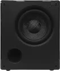
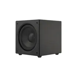
Your new Sonance Cabinet Subwoofer delivers powerful, low-
distortionbass,andeasilytsintoyourroom’sdécor.
• Textured Black Finish with Black Cloth Grille
for Elegant and Minimalistic Aesthetic
• Made for Music and Movies
• Ultra Long Throw, Polypropylene Cone
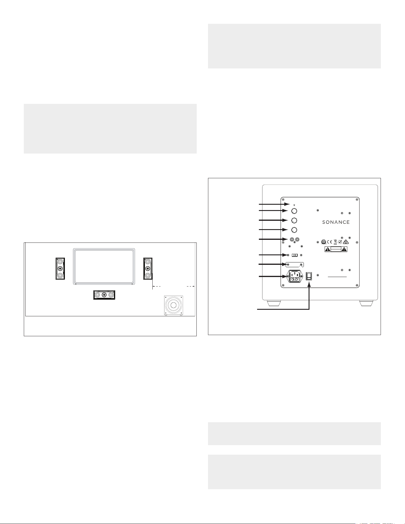
Subwoofer Placement
Since your ears do not hear directional sound at deep bass
frequencies, your subwoofer’s placement is not as critical to its
overall performance as is the placement of your system’s other
speakers. The following guidelines — plus some experimentation
- will help you get the best performance possible from your
subwoofer in your listening environment. We suggest starting with
the subwoofer in line with your left and right speakers, somewhere
between either speaker and the side wall (see Figure 1).
Installing the Subwoofer Flush to a Wall
or Cabinet
To allow for proper ventilation when installing the cabinet subwoofer
this way, leave at least 1” of clearance around the top and sides of
the subwoofer and 1” of clearance behind it. If it is not possible to
provide the necessary clearance, install a fan that will bring cooling
air into the rear of the compartment containing the subwoofer.
Yoursubwoofer’slocationrelativetowallswillinuencetheamount
of bass it produces. Placing the subwoofer next to a wall will
increase bass output; placing it in a corner will maximize its bass
output. However, corner placement can increase standing waves
in the room (peaks and dips in bass response related to the room’s
dimensions) that can make the subwoofer’s bass performance
soundunevenatdierentlisteninglocations.Experimentwith
dierentsubwooferlocationsuntilyoundonethatproduces
strong bass that sounds clear (without boominess) at the seating
locations while maintaining the sound’s impact.
Your local authorized Sonance dealer is an expert in audio/video
system planning and installation. We strongly recommend that you
work with your dealer to ensure that you get the best performance
possible from your subwoofer.
NOTE: SONANCE SUBWOOFERS CAN PRODUCE ENOUGH BASS ENERGY
TO CAUSE OBJECTS IN THE ROOM TO RATTLE OR BUZZ DURING
PASSAGES WITH VERY STRONG BASS. IF THIS HAPPENS, TRY
RELOCATING THE ITEMS. IF THAT FAILS TO STOP THE RATTLING YOU
MAY HAVE TO REMOVE OR SECURE THE ITEMS.
Between
Main Speaker
and Side Wall
Figure1:StartwiththeSubwooferLocated
Between a Main Speaker and the Side Wall.
Subwoofer Rear Panels
Figure 2 shows the controls and connections located on the
subwoofer rear panel.
Status
Volume
Crossover
Phase
Power Cord
Connection
Power Switch
Ground Lift
Line Level Input
AC Mains
STATUS
LINE LEVEL INPUT
VOLUME
MIN MAX
CROSSOVER
50HZ
250HZ
150HZ
75HZ 200HZ
BYPASS
0 DEG 180 DEG
90 DEG
PHASE
RIGHTLEFT / LFE
GROUND LIFT
GROUNDED
ISOLATED
100 -120V 220 –240V
FUSE T4AL/250VAC
AC 100-120V ~ 60Hz
AC 220-240V ~ 50Hz
ON
OFF
POWER
S/N
MADE IN CHINA
This device complies with part 15 of the FCC
Rules.
Operation is subject to the following two
conditions:
(1) This device may not cause harmful
interference.
(2) This device must accept any interference
received, including interference that may cause
undesired operation.
FCC COMPLIANCE NOTICE
CAUTION
RISK OF ELECTRIC SHOCK DO NOT OPEN
RISQUE DE CHOC ELECTRONIQUE NE PAS OUVRIR
AVIS
GMA-503573-EA
MS10SUB
Figure2:SubwooferRear-PanelControlsandConnections.
Box Contents
(1) Sonance Cabinet Subwoofer
(4) Removable Rubber Feet
(1) IEC Power Cord
Subwoofer Connections
Power Connection
Your MS10SUB Cabinet Subwoofer features a removable IEC
power connector for 115V (see Figure 2). Plug the female end of
the power cord into the power cord connector on the subwoofer’s
rear panel and plug the male end into a grounded wall socket. DO
NOT plug the subwoofer’s power cord into a convenience outlet on
any other audio or video component. Power Consumption
Standby Mode 0.46W after 30 minutes without signal.
IMPORTANT: DO NOT PLUG THE POWER CORD INTO THE WALL OUTLET
UNTIL ALL SYSTEM CONNECTIONS HAVE BEEN MADE AND VERIFIED.
NOTE: IF YOU NEED TO USE AN EXTENSION CORD, USE ONLY A HEAVY-
DUTY (14-GAUGE OR LARGER) EXTENSION CORD TO AVOID STARVING
THE SUBWOOFER OF ALL THE CURRENT NECESSARY FOR FULL-
POWER OPERATION.
4
5
NOTE: DO NOT PLUG THE POWER CORD INTO A POWER CONDITIONER
OR UPS SYSTEM.
Audio Connections
YourSonanceCabinetSubwooferhasexibleconnectionsthatlet
youuseitinawidevarietyofaudiosystemcongurations
(see Figure 2).
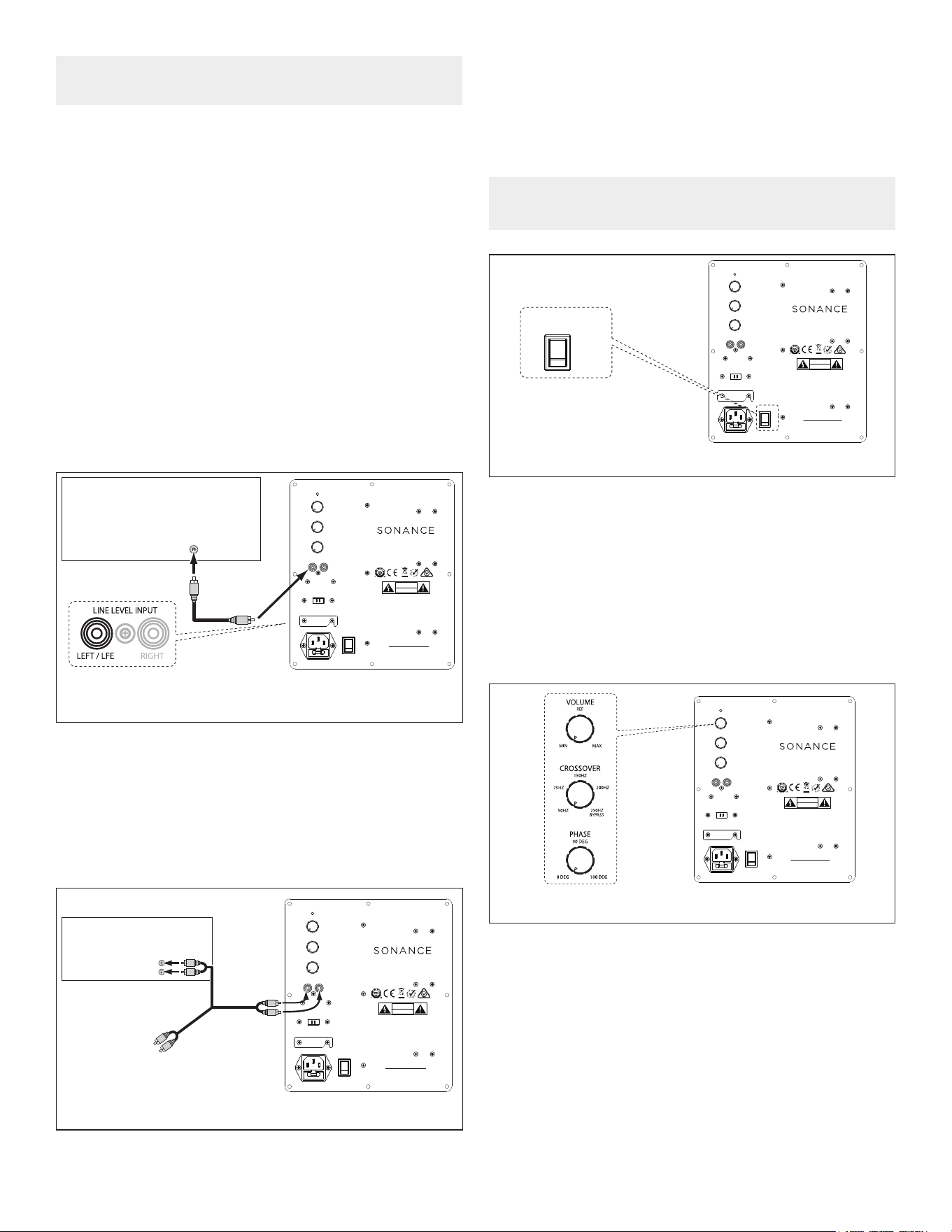
Line Level
You can connect the subwoofer’s line level input to a surround
processor or receiver’s line-level dedicated subwoofer LFE output
orastereopreamp/integratedamplier’sleftandrightvariablemain
outputs.
Connect the processor’s dedicated subwoofer output to the left
line level input jack labeled LEFT/LFE. If you are installing two
subwoofers in the system, use a ‘Y’ connector to connect both
subwoofers to the processor’s subwoofer output.
Option 2
Stereo preamp/power amp combination or an integrated
amplierwithpreampoutjacks(seeFigure4).
Connection Examples
Follow the connection example that best describes your audio
system. The examples are listed in descending order of preference,
withthemostidealmethodpresentedrst.
Option 1
Surround sound processor, surround sound receiver, or stereo
preamp with a dedicated subwoofer output (see Figure 3).
LFE
SUBWOOFER
OUTPUT
Surround
Processor/Receiver
Sonance
Subwoofer
AUDIO CABLE
STATUS
LINE LEVEL INPUT
VOLUME
MIN MAX
CROSSOVER
50HZ
250HZ
150HZ
75HZ 200HZ
BYPASS
0 DEG 180 DEG
90 DEG
PHASE
RIGHTLEFT / LFE
GROUND LIFT
GROUNDED
ISOLATED
100 -120V 220 –240V
FUSE T4AL/250VAC
AC 100-120V ~ 60Hz
AC 220-240V ~ 50Hz
ON
OFF
POWER
S/N
MADE IN CHINA
This device complies with part 15 of the FCC
Rules.
Operation is subject to the following two
conditions:
(1) This device may not cause harmful
interference.
(2) This device must accept any interference
received, including interference that may cause
undesired operation.
FCC COMPLIANCE NOTICE
CAUTION
RISK OF ELECTRIC SHOCK DO NOT OPEN
RISQUE DE CHOC ELECTRONIQUE NE PAS OUVRIR
AVIS
GMA-503573-EA
MS10SUB
STATUS
LINE LEVEL INPUT
VOLUME
MIN MAX
CROSSOVER
50HZ
250HZ
150HZ
75HZ 200HZ
BYPASS
0 DEG 180 DEG
90 DEG
PHASE
RIGHTLEFT / LFE
GROUND LIFT
GROUNDED
ISOLATED
100 -120V 220 –240V
FUSE T4AL/250VAC
AC 100-120V ~ 60Hz
AC 220-240V ~ 50Hz
ON
OFF
POWER
S/N
MADE IN CHINA
This device complies with part 15 of the FCC
Rules.
Operation is subject to the following two
conditions:
(1) This device may not cause harmful
interference.
(2) This device must accept any interference
received, including interference that may cause
undesired operation.
FCC COMPLIANCE NOTICE
CAUTION
RISK OF ELECTRIC SHOCK DO NOT OPEN
RISQUE DE CHOC ELECTRONIQUE NE PAS OUVRIR
AVIS
GMA-503573-EA
MS10SUB
MAIN
OUTPUTS
Preamp/Integrated Amp
L
R
AUDIO CABLE
Sonance
Subwoofer
TO AMP
Figure3:ConnectingtoaSurround
Processor’s Subwoofer Output
Figure4:ConnectingBetweenaStereoPreamp/IntegratedAmp
Connectthepreamp/integratedamplier’sleftandrightmain
outputs to the subwoofer’s line level input jacks.
Figure5:SubwooferAdjustments
Sonance
Subwoofer
STATUS
LINE LEVEL INPUT
VOLUME
MIN MAX
CROSSOVER
50HZ
250HZ
150HZ
75HZ 200HZ
BYPASS
0 DEG 180 DEG
90 DEG
PHASE
RIGHTLEFT / LFE
GROUND LIFT
GROUNDEDISOLATED
100 -120V 220 –240V
FUSE T4AL/250VAC
AC 100-120V ~ 60Hz
AC 220-240V ~ 50Hz
ON
OFF
POWER
S/N
MADE IN CHINA
This device complies with part 15 of the FCC
Rules.
Operation is subject to the following two
conditions:
(1) This device may not cause harmful
interference.
(2) This device must accept any interference
received, including interference that may cause
undesired operation.
FCC COMPLIANCE NOTICE
CAUTION
RISK OF ELECTRIC SHOCK DO NOT OPEN
RISQUE DE CHOC ELECTRONIQUE NE PAS OUVRIR
AVIS
GMA-503573-EA
MS10SUB
ON
OFF
POWER
POWER SWITCH
Power On/O
Once the subwoofer is properly connected for power and signal,
engage the POWER switch from OFF to ON (see Figure 5).
NOTE: NO SIGNAL WILL BE PASSED IF THE POWER SWITCH IS NOT
PROPERLY SELECTED.
Subwoofer Adjustments
Volume Adjustments
The VOLUME control sets the subwoofer’s volume output. When
settingthesubwoofer’svolumecontrolbyear,trytondavolume
settingwherethebasssoundsbalancedonbothmusicandlms.
Listentoseveraldierentmusicrecordingsandlmsoundtracks
thatcontainstrongbasspassagesandtrytondasettingforthe
volume control that doesn’t over-emphasize the bass or make it
sound weak (see Figure 6).
The most accurate way to set the volume control is with calibrated
test noise or test tones and a sound-pressure level (SPL) meter
or real time analyzer. There are several CDs and DVDs that
contain subwoofer test signals. If you use an SPL meter, set the
subwoofer’s volume control so that it plays at the same volume as
the system’s other speakers.
Figure6:SubwooferAdjustments
STATUS
LINE LEVEL INPUT
VOLUME
MIN MAX
CROSSOVER
50HZ
250HZ
150HZ
75HZ 200HZ
BYPASS
0 DEG 180 DEG
90 DEG
PHASE
RIGHTLEFT / LFE
GROUND LIFT
GROUNDED
ISOLATED
100 -120V 220 –240V
FUSE T4AL/250VAC
AC 100-120V ~ 60Hz
AC 220-240V ~ 50Hz
ON
OFF
POWER
S/N
MADE IN CHINA
This device complies with part 15 of the FCC
Rules.
Operation is subject to the following two
conditions:
(1) This device may not cause harmful
interference.
(2) This device must accept any interference
received, including interference that may cause
undesired operation.
FCC COMPLIANCE NOTICE
CAUTION
RISK OF ELECTRIC SHOCK DO NOT OPEN
RISQUE DE CHOC ELECTRONIQUE NE PAS OUVRIR
AVIS
GMA-503573-EA
MS10SUB
Sonance
Subwoofer
6
CAUTION: FOR CONTINUED PROTECTION AGAINST FIRE, REPLACE THE
FUSE WITH ONLY THE SAME TYPE AND RATING.
Figure7:PowerCordConnectorandFuseHolder
STATUS
LINE LEVEL INPUT
VOLUME
MIN MAX
CROSSOVER
50 HZ
250 HZ
150 HZ
75HZ 200 HZ
BYPASS
0 DEG 180 DEG
90 DEG
PHASE
RIGHTLEFT / LFE
GROUND LIFT
GROUNDED
ISOLATED
100 -120V 220 –240V
FUSE T4 AL / 250 VAC
AC 100-120V ~ 60Hz
AC 220-240V ~ 50Hz
ON
OFF
POWER
S/N
MADE IN CHINA
This device complies with part 15 of the FCC
Rules.
Operation is subject to the following two
conditions:
(1) This
device may not cause harmful
interferenc
e.
(2) This d
evice must accept any interference
received, i
ncluding interference that may cause
undesired
operation.
FCC COMPLIANCE NOTICE
CAUTION
RISK OF ELECTRIC SHOCK DO NOT OPEN
RISQUE DE CHOC ELECTRONIQUE NE PAS OUVRIR
AVIS
GMA-503573-EA
MS10SUB
Crossover Adjustments
The crossover control adjusts the subwoofer’s internal crossover
frequency between 50Hz and 250Hz. The crossover’s slope is
18dB/octave. The higher you set the crossover control, the higher
in frequency the subwoofer will operate. Use the crossover control
to achieve a smooth transition of bass frequencies between the
subwoofer and your main speakers. Generally, the crossover
control should be set at a lower frequency if your main speakers
have larger woofers, and at a higher frequency if your main
speakers have smaller woofers (see Figure 6).
When setting the crossover control by ear, listen for the
smoothness of the bass. If the bass seems too strong at certain
frequencies (especially if your main speakers have larger woofers),
try a lower crossover control setting. If the bass seems too weak at
certain frequencies (especially if your main speakers have smaller
woofers), try a higher crossover control setting.
Ideally, the crossover control should be set to the frequency where
yourmainspeakerslow-frequencyresponserollois-3dBdown.
Phase Adjustments
When the subwoofer’s PHASE switch is in the 0 position, a positive
input voltage will cause the woofer cone to move out towards the
room. When the phase switch is in the 180 position, a positive input
voltage will cause the woofer cone to move in away from the room
(see Figure 6).
There is no absolute correct setting for the phase switch.
Depending on the location of the subwoofer relative to your main
speakers and seating location, one of the settings will produce a
better match with the main speakers, improving bass impact and
in some cases, improving overall bass level as well.
To determine the correct setting of the phase switch, listen to
musicwithsignicantimpactfulbasscontentwiththeswitchin
each position. It may be helpful to sit in the normal listening position
while someone else changes the phase switch between 0 and 180.
Leave the switch in the position that produces audibly louder bass
with more impact.
Ground Lift
Your Sonance Cabinet Subwoofer features a ground lift switch
available to eliminate most ground hum issues. To reduce the
ground current and induced noises, switch the ground lift from
isolatedtogrounded.Safetyisnotaected(seeFigure7).
Replacing the AC Fuse
Yoursubwooferisfactory-equippedwiththefollowingACfuse:
T4 AL / 250 VAC
To replace the fuse, unplug the power cord from the Power Cord
Connector and use a screwdriver to remove the fuse holder
(see Figure 7).
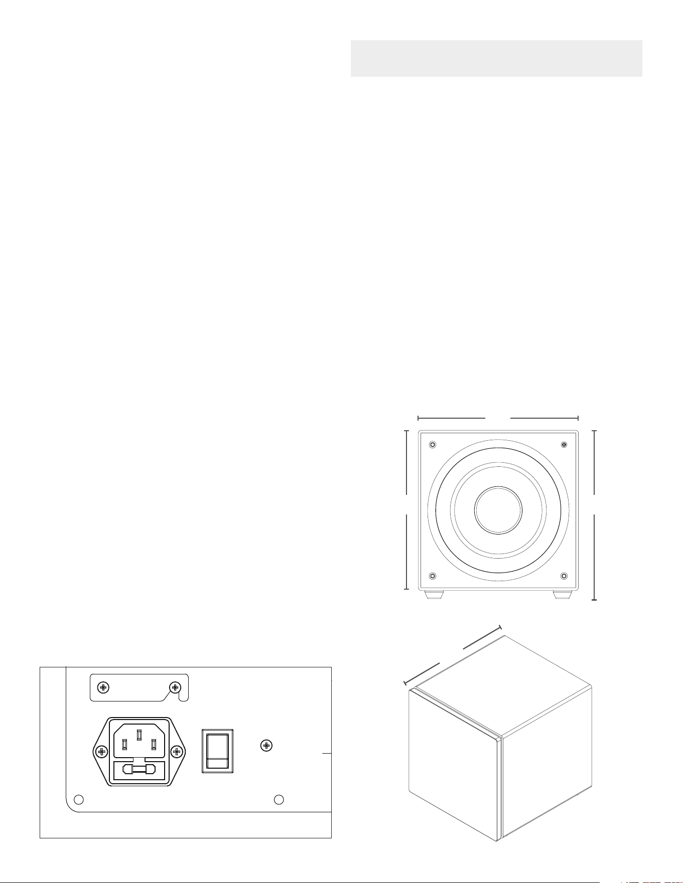
Specications
Model:
SKU:
Woofer:
FrequencyResponse:
Enclosure Material:
Power Output:
Inputs:
Controls:
Cabinet Dimensions:
(W x H x D)
Height with Feet:
Grille Material:
Shipping Weight:
MS10SUB
93447
10” (254mm) ultra long throw,
polypropylene cone, rubber surround
27Hz - 250Hz +/-3dB
MDFwithtexturedblacknish
275 watts RMS (550 watts peak)
Line-level (Left/LFE and Right)
Volume, crossover, and variable phase
11.8” x 11.8” x 12.6”
(300mm x 300mm x 320mm)
12.2” (310mm)
Black cloth
38 lbs (17.24kg)
11.8”
11.8”
12.2”
12.6”

©2019 Sonance. All rights reserved. Sonance is a registered trademark of Dana Innovations. Due to continuous product improvement, all features and
specicationsaresubjecttochangewithoutnotice.ForthelatestSonanceproductspecicationinformationvisitourwebsite:www.sonance.com
SONANCE•991CalleAmanecer•SanClemente,CA92673USA•(949)492-7777•FAX:(949)361-5151• www.sonance.com
LIMITED THREE (3) YEAR WARRANTY
Sonancewarrantstotherstend-userpurchaserthatthisSonance-brandproduct(product),whenpurchasedfromanauthorizedSonance
Dealer/Distributor, will be free from defective workmanship and materials for the period stated below. Sonance will at its option and expense
during the warranty period, either repair the defect or replace the Product with a new or remanufactured Product or a reasonable equivalent.
EXCLUSIONS
TO THE EXTENT PERMITTED BY LAW, THE WARRANTY SET FORTH ABOVE IS IN LIEU OF, AND EXCLUSIVE OF, ALL
OTHER WARRANTIES, EXPRESS OR IMPLIED, AND IS THE SOLE AND EXCLUSIVE WARRANTY PROVIDED BY SONANCE.
ALL OTHER EXPRESS AND IMPLIED WARRANTIES, INCLUDING THE IMPLIED WARRANTIES OF MERCHANTABILITY,
IMPLIED WARRANTY OF FITNESS FOR USE, AND IMPLIED WARRANTY OF FITNESS FOR A PARTICULAR PURPOSE ARE
SPECIFICALLY EXCLUDED.
No one is authorized to make or modify any warranties on behalf of Sonance. The warranty stated above is the sole and exclusive remedy
andSonance’sperformanceshallconstitutefullandnalsatisfactionofallobligations,liabilitiesandclaimswithrespecttotheProduct.
IN ANY EVENT, SONANCE SHALL NOT BE LIABLE FOR CONSEQUENTIAL, INCIDENTAL, ECONOMIC, PROPERTY, BODILY
INJURY, OR PERSONAL INJURY DAMAGES ARISING FROM THE PRODUCT, ANY BREACH OF THIS WARRANTY OR
OTHERWISE.
Thiswarrantystatementgivesyouspeciclegalrights,andyoumayhaveotherrightswhichvaryfromstatetostate.Somestatesdonot
allow the exclusion of implied warranties or limitations of remedies, so the above exclusions and limitations may not apply. If your state does
not allow disclaimer of implied warranties, the duration of such implied warranties is limited to period of Sonance’s express warranty.
YourProductModelandDescription:SonanceMS10SUBSubwoofer
WarrantyPeriodforthisProduct:Three(3)yearsfromthedateontheoriginalsalesreceiptorinvoiceorothersatisfactoryproofofpurchase.
AdditionalLimitationsandExclusionsfromWarrantyCoverage:Thewarrantydescribedaboveisnon-transferable,appliesonlytotheinitial
installation of the Product, does not include installation of any repaired or replaced Product, does not include damage to allied or associated
equipment which may result for any reason from use with this Product, and does not include labor or parts caused by accident, disaster,
negligence,improperinstallation,misuse(e.g.overdrivingtheamplierorspeaker,excessiveheat,coldorhumidity),orfromserviceorrepair
whichhasnotbeenauthorizedbySonance.ObtainingAuthorizedService:Toqualifyforthewarranty,youmustcontactyourauthorized
Sonance Dealer/Installer or call Sonance Customer Service at (949) 492-7777 within the warranty period, must obtain a return merchandise
number (RMA), and must deliver the Product to Sonance shipping prepaid during the warranty period, together with the original sales
receipt, or invoice or other satisfactory proof of purchase.
05.30.19
7