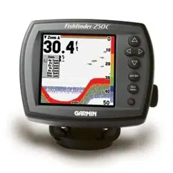
Fishnder 300C Installation Instructions
Compare the contents of this package with the packing list on the box. If any pieces are missing, contact your Garmin dealer immediately.
Before you begin the installation:
Read and follow the instructions to install the Fishnder 300C.
Gather the appropriate fasteners and tools.
Verify that all cables can reach the Fishnder 300C mounting location and the transducer.
Wear safety goggles and a dust mask when drilling, cutting, or sanding.
If you experience difculty installing the Fishnder 300C, contact Garmin Product Support or contact a professional installer.
WARNING: See the Important Safety and Product Information guide in the product box for product warnings and other important
information.
To install and use your Fishnder 300C:
1. Select a location.
2. MounttheFishnder300C.
3. Installthetransducer.
4. Installthewiringharness.
5. Test the installation.
Step 1: Select a Location for the Fishnder 300C
Consider the following when you select an installation location:
Provide optimal viewing as you operate your vessel.
Allow easy access to the keypad on the Fishnder 300C.
Is strong enough to support the weight of the Fishnder 300C and protect it from excessive vibration or shock.
Allow room for the routing and connection of the cables. There should be at least a 3-inch (8 cm) clearance behind the case.
DO NOT mount the Fishnder 300C in an area that is exposed to extreme temperature conditions.
NOTE: The temperature range for the Fishnder 300C is from 5°F to 131°F (from -15°C to 55°C). Extended exposure to temperatures exceeding this
range (in storage or operating conditions) may cause failure of the LCD screen or other components. This type of failure and related consequences are
not covered by the manufacturer’s limited warranty.
Step 2: Mount the Fishnder 300C
You can mount your Fishnder 300C in one of two ways:
Bail Mount—mount the Fishnder 300C onto the bracket that attaches to the console or overhead.
Flush Mount—use the ush mount kit to mount the Fishnder 300C into a at panel.
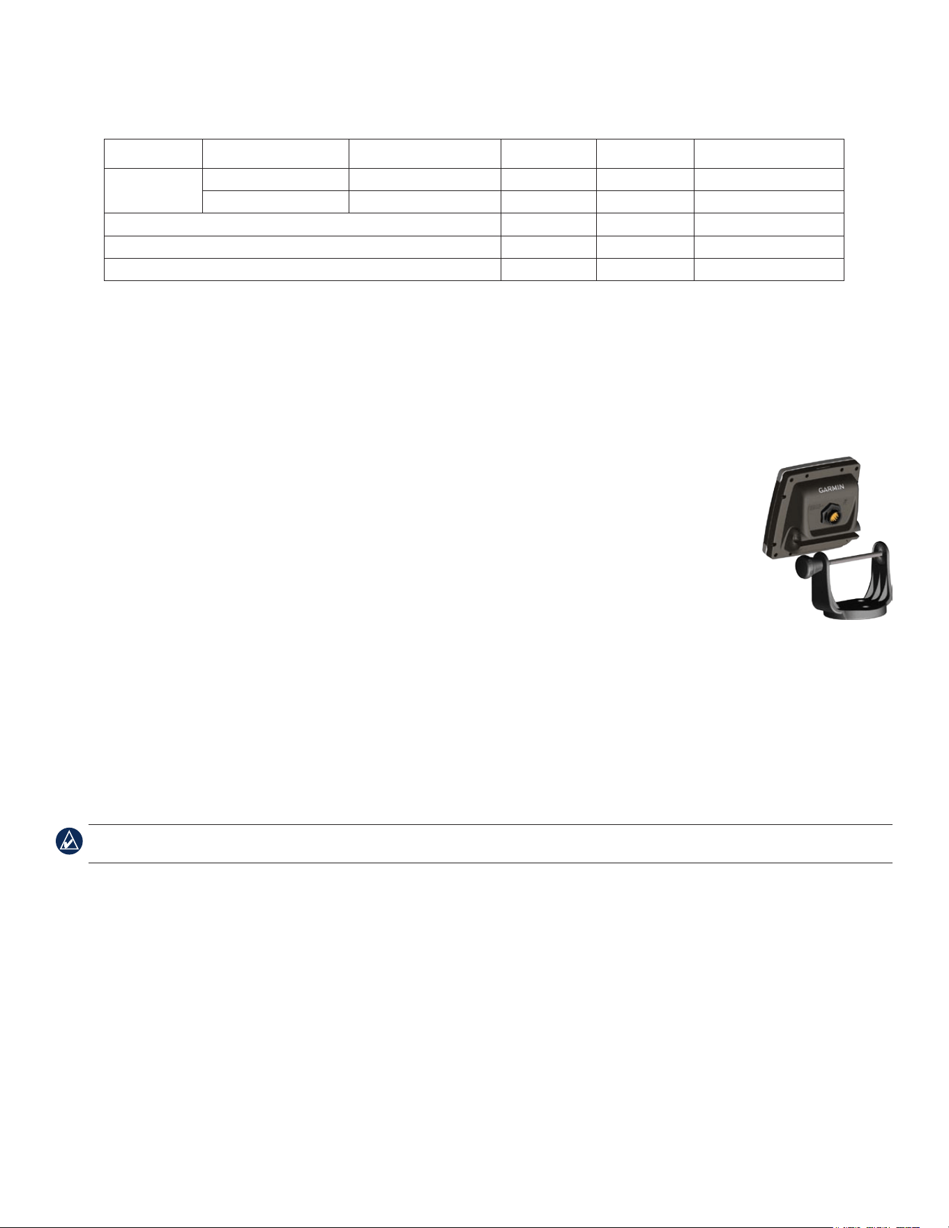
Bail Mounting the Fishnder 300C
The Fishnder 300C is suitable for mounting in exposed locations or at the navigation station. The included tilt mounting bracket can be used
for console or overhead mounting. Bail mounting requires the following tools and hardware:
Three of the included number 8 (4.2 × 1.4 DIN7981) ANSI mounting screws
Phillips-head screwdriver (not included)
Drill and drill bit (not included)
Center punch and hammer (not included)
•
•
•
•
•
•
•
•
•
•
•
•
•
•
December 2007 190-00864-03 Rev. B Printed in Taiwan
2 Fishnder 300C Installation Instructions
Use the following table to determine the drill bit size:
Material Material Thickness (in.) Material Thickness (mm) Hole Size (in.) Hole Size (mm) Hole Size (Drill Number)
Aluminum alloy
sheet metal
from1/32to5/64 from0.76to2.03
.128 3.25 30
from3/32to3/8 from2.28to9.52
.147 3.73 26
Fiberglass-allthicknesses
.140 3.56 28
HighDensityPlastic-allthicknesses
.125 3.17 1/8
Plywood(resinimpregnated)—Professionalinstallationrecommended
.144 3.66 27
Drill Size Table
To mount the bracket assembly:
1. Usingthebaseofthebracketasatemplate,markthelocationofthethreeholes(twoscrewstowardsthefront,onescrewtowardsthe
back).
2. Usingthecenterpunch,indentthecenterofeachofthethreemounting-holelocations.
3. Drillthemountingholes,usingthebitsizeindicatedintheDrillSizeTableabove.
4. Securethebasewiththethreeincludedscrews.
To install the Fishnder 300C on the mounting bracket:
1. AligntheslotonthebackoftheFishnder300Cwiththemountingknob,andslidetheshnderintoplace.If
necessary,adjusttheknobtospreadthebracketarmsapart.
2. AdjusttheFishnder300Cangleandtightentheknobuntilsnug.
Flush Mounting the Fishnder 300C
In addition to four of the included number 8 ANSI (4.2 × 1.4 DIN7981) mounting screws, ush mounting the Fishnder
300C requires the following tools:
Phillips-head screwdriver
Drill and drill bit (refer to Drill Size Table above for drill size) for mounting holes
3/8" (10 mm) drill bit for pilot hole
Jigsaw
Scissors
Center punch and hammer
File and sandpaper
Anti-seize lubricant (optional)
NOTE: Ensure that the surface on which you mount the Fishnder 300C has sufcient open space behind it to accommodate the Fishnder 300C and
the connected wires.
To ush mount the Fishnder 300C:
1. Theush-mounttemplateisincludedintheproductbox.Trimthetemplateandensureitwilltinthelocationwhereyouwanttoushmount
theFishnder300C.
2. Theush-mounttemplatehasadhesiveontheback.Removetheprotectivelinerandapplythetemplatetothelocationatwhichyouwantto
mounttheFishnder300C.
3. Usingthecenterpunch,indentthecenterofeachofthefourmounting-holelocations.
4. UsingadrillbitasspeciedbytheDrillSizeTable,drillthefourmountingholes.
5. Usinga3/8"(9mmor10mm)drillbit,drillapilotholeinsidethecornerofthetemplatetobegincuttingthemountingsurface.
6. Usingthejigsaw,cutthemountingsurfacealongtheinsideofthesolidlineindicatedontheush-mounttemplate.Usealeandsandpaper
torenethesizeofthehole.
7. ApplytheadhesivesideofthegaskettothebackoftheFishnder300C.
•
•
•
•
•
•
•
•
3Fishnder 300C Installation Instructions
8. IfthetopandbottommountingcoversareattachedtothefrontoftheFishnder300C,removethembyunsnappingthecoversfromthe
sides.
9. PlacetheFishnder300Cintothecutout.
Mounting covers
10.SecurelytightenthefourmountingscrewsthroughtheFishnder300Cintothedrilledmountingholes.
NOTE: Stainless-steel screws may bind when screwed into berglass and overtightened. Garmin recommends applying an anti-galling stainless anti-
seize lubricant to the screw before using.
11.Replacethemountingcoversbysnappingthemintoplace.
Step 3: Install the Transducer
The following instructions describe the basic installation of typical transducers, such as the one included with your Fishnder 300C. Additional
installation instructions are provided in the transducer kits. Some transducers may have to be installed by a professional marine installer.
CAUTION: DO NOT cut the transducer lead or any part of the transducer cable. Cutting the transducer cable voids your warranty. The cable cannot be
spliced and connected to any existing (Garmin or non-Garmin) transducer cables.
If the transducer lead is too short, extension cables are available from your Garmin dealer. Coil and secure any excess cable.
Assembling the Transducer
To assemble the transducer:
1.Inserttherubberwasherandtheplasticspacerintothetransduceratthesametime.DONOTlubricatetherubberwasher.
2. Routethecabletowardthebackofthetransducer.Slidethetransducerintothetransducermount.
3.Placethe5mmatwasheronthe10-32×1.75"screw,andinsertthescrewthroughthetransducermount,thespacer,andtherubber
washer.
4.Placetheremaining5mmatwasherontheexposedend.Installthe10-32locknutngertight.Retightenthetransducerafterinstallationon
the boat.
Back of the transducer
Cable-tie slot
4 Fishnder 300C Installation Instructions
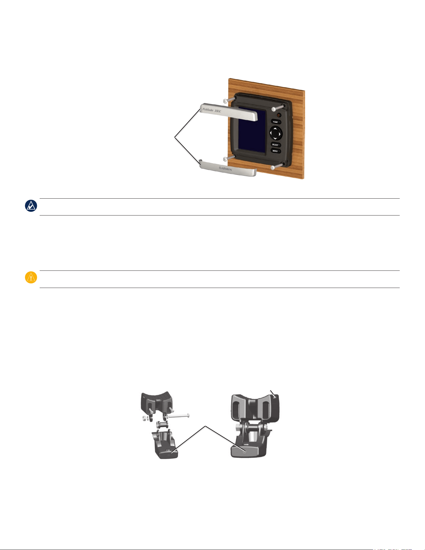
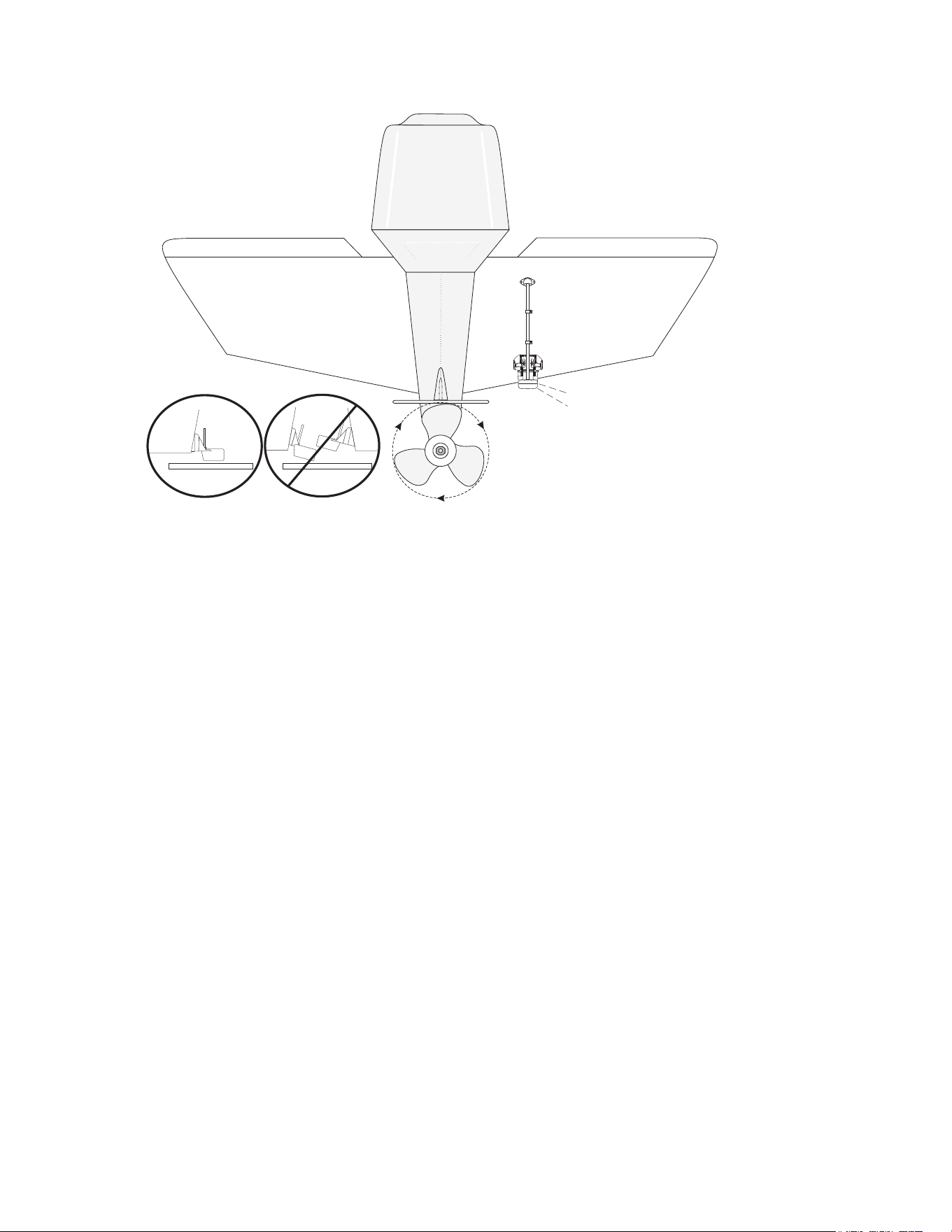
Mounting the Transducer on a Trolling Motor
To mount the transducer on a trolling motor:
1.Slidethelargecabletiethroughtheslotonthetransducermount,withtheridgesofthecabletiefacingup,untilequallengthsofcabletie
extendonbothsidesofthemount.
NOTE: For cold water, or heavy timber or debris areas, a metal 4–5" (100–130 mm) worm-gear clamp is recommended.
2. Positionthemountgasketonthecurvedtopofthetransducermount.
3.Placethetransducerassemblyagainstthemotorbodyofthetrollingmotor,withthefrontofthetransducerpointedawayfromthe
trolling-motorpropeller.
4.Wrapthetwoendsofthecabletiearoundthemotorbody.Placethepointedendofthecabletiethroughthefastenerholeontheopposite
endandpullitthroughuntilitissnugbutnottight.(Thecabletieclickswhenyoupullit.)
5. Positionthetransducersothatitisparallelwiththebottomwheninuse,andmakesurethegasketisalignedproperly.Pullthecable-tie
enduntiltight.Trimofftheexcessifnecessary.Tightenthe10-32lockingnutuntilittouchesthemountingbracket,andthentighten1/4turn
more.(Donotovertighten.)
6.Routethe30-foot(9m)transducercableusingthesuppliedcabletiestosecurethecabletothemotorshaft.Youcanlltheforward-facing
portion(exceptthecable-tiepocket)ofthetransducermountwithsealanttoavoidaccumulatingdebris.
Cable tie
Front of the transducer
Mounting the Transducer on a Transom
When selecting a transom-mount location, consider the following for optimal performance:
For your sonar to operate properly, the transducer must be located in calm water.
Mount the transducer as close to the center of the boat as possible.
DO NOT cut the transducer lead. (This voids your warranty.)
DO NOT mount the transducer in locations where it might be jarred when launching, hauling, or storing.
DO NOT mount the transducer in the path of the propeller on single-drive boats. The transducer can cause cavitation that can degrade the
performance of the boat and damage the propeller. On twin-drive boats, mount the transducer between the drives, if possible.
NOTE: DO NOT mount the transducer behind strakes, struts, ttings, water intake or discharge ports, or anything that creates air bubbles or causes the
water to become turbulent. The transducer must be in clean (non-turbulent) water for optimal performance.
•
•
•
•
•
5Fishnder 300C Installation Instructions
Apply marine sealant to all screw
threads to prevent water from
seeping into the transom.
Mount the transducer
cable cover well above
the waterline.
Transducer should extend 1/8" (3.2 mm)
below a berglass hull or 3/8" (9.5 mm)
below an aluminum hull.
Ensure that the transducer is
below water level when the boat
is on plane at high speed.
Do not mount the transducer directly in the path of the
propeller. The transducer can cause cavitation that may
degrade the boat performance and damage the propeller.
Mount the transducer parallel
with the bottom.
Required Tools (not included)—drill, 3/8" wrench or socket, 5/32" (4 mm) and 1/8" (3.2 mm) drill bits, masking tape, number 2 Phillips
screwdriver, and marine sealant.
To mount the transducer on a transom:
1.Positionthetransducermountattheselectedtransomlocation.Makesurethetransducerisparallelwiththewaterline.Markthecenter
locationsofeachholeonthetransducermount.
2.Usinga5/32"(4mm)bit,drillthepilotholesapproximately1"(25mm)deepatthemarkedlocations.Toavoiddrillingtheholestoodeep,
wrapapieceoftapearoundthebitat1"(25mm)fromthepointofthebit.
3.Applymarinesealanttothe5×30mmscrews.Attachthetransducerassemblytothetransomusingthe5×30mmscrews.Adjust
thetransducerassemblytoextendbeyondthebottomofthetransomapproximately1/8"(3mm)onberglasshullsor3/8"(10mm)on
aluminumhulls.Adjustthetransducerassemblytobealignedparallelwiththewater.
4.Tightenthe10-32lockingnutuntilittouchesthemountingbracket,andthentighten1/4turnmore.(Donotovertighten.)
5.Placetherstcableclamponthetransducercable,approximatelyonethirdofthedistancebetweenthetransducerandthetopofthe
transom.
6. Markthelocation.Usinga1/8"(3.2mm)bit,drillapilotholeapproximately3/8"(10mm)deep.
7.Attachthecableclampusingoneofthe4×12mmscrews.Coatthescrewwithmarinesealantbeforeinstallation.Repeatsteps5and6
usingtheothercableclamp.
8. RoutethetransducercabletotheFishnder300C.Donotcutthecable.Avoidroutingthecableclosetoelectricalwiresorothersourcesof
electricalinterference.
6 Fishnder 300C Installation Instructions
Step 4: Install the Wiring Harness
The Fishnder 300C comes with a cable assembly that connects it to power and to the transducer with one connection and provides interface
capabilities for connecting external devices.
The color code in the diagram on page 7 indicates the appropriate harness connections. The replacement fuse is an AGC/3AG 3A fuse. If it is
necessary to extend the power wires, use 22 AWG wire. Do not cut the transducer cable. Cutting the transducer cable voids your warranty. If
your boat has an electrical system, you might be able to wire the Fishnder 300C directly to an unused holder on your current fuse block. If you
are using the fuse block, remove the in-line fuse holder supplied with the Fishnder 300C. You can also wire the Fishnder 300C directly to the
battery.
CAUTION: The Fishnder 300C maximum input voltage is 33 Vdc. Do not exceed this voltage, because this can damage the Fishnder 300C and void
the warranty.
NOTE: During a typical installation, use only the red and black wires. The other wires do not have to be connected for normal operation of the
Fishnder 300C. For information on connecting to a NMEA 0183-compatible device, see page 7.
To install the wiring harness:
1. Useatestlightorvoltmetertodeterminethepolarityofthevoltagesource.
2. Connectthered(+orpositive)wiretothepositivevoltageterminal.(Ifyouusethefuseblockontheboat,routethepositiveconnection
throughthefuse,asshownonthediagram.)
3. Connecttheblack(-orground)wiretothenegativevoltageterminal.
4. Installorcheckthe3Afuse(onthefuseblockorinthein-lineholder).
5. AlignthenotchesonthecableplugandonthebackoftheFishnder300C.Insertthecableintotheconnector,andturnthelockingring
counter-clockwiseuntilitstops.
—
+
To 10–38 volt boat supply
3A
+
Boat ground
3A fuse
To Fishnder 300C
Fuse block
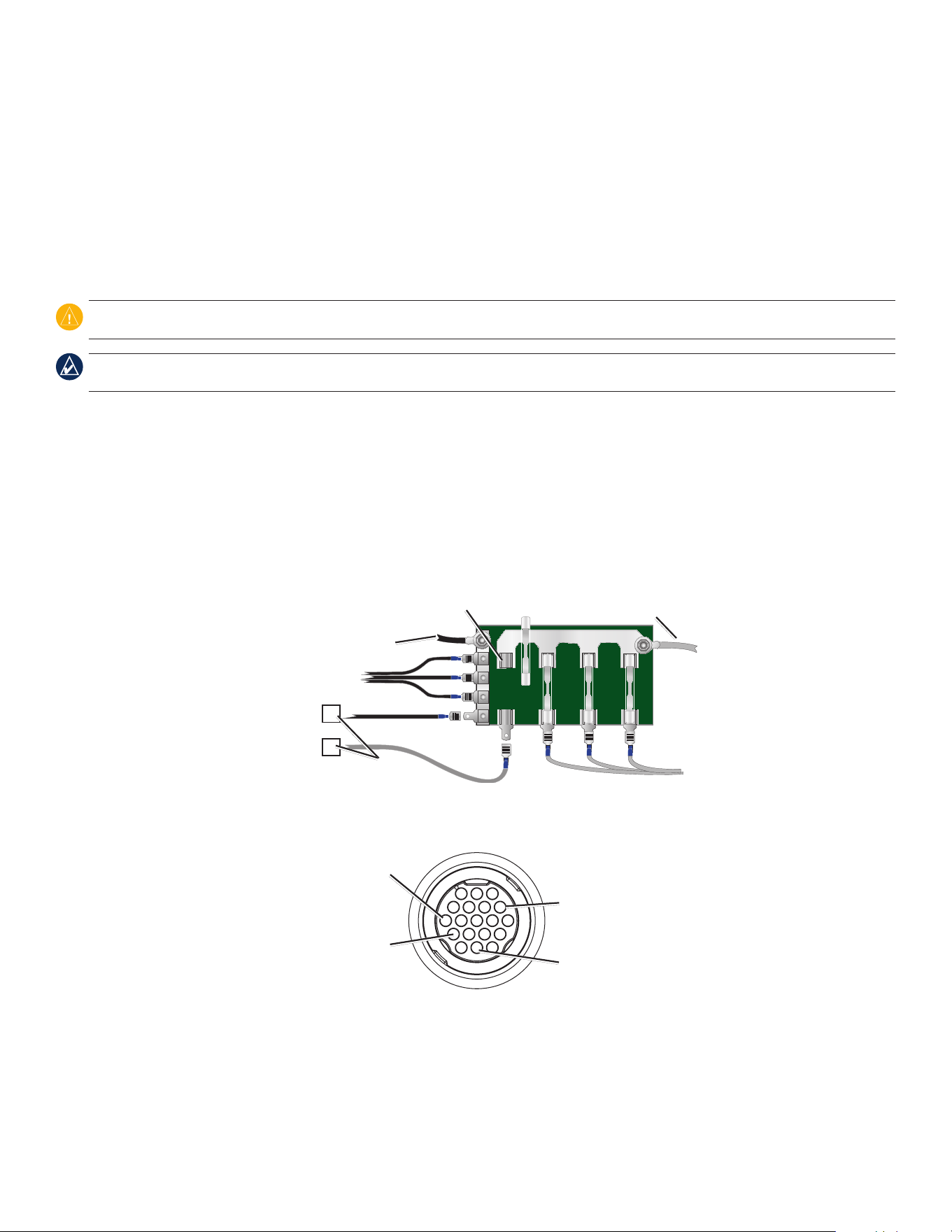
Pin 8 - ground (black)
Pin 18 - NMEA out (blue)
Pin 13 - dc positive (red)
Pin 7 - alarm (yellow)
Fishnder 300C Power/Data
Cable Pin Assignment
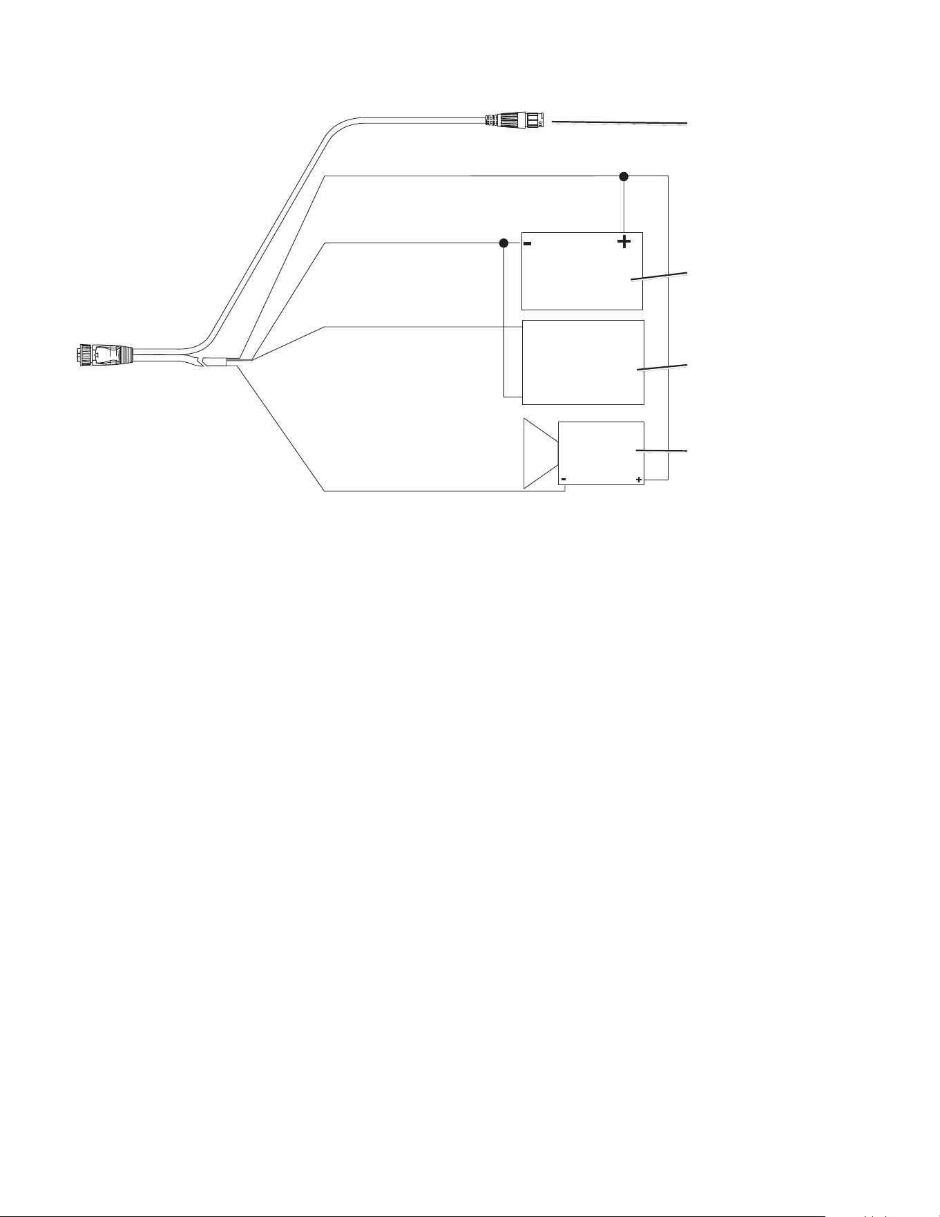
7Fishnder 300C Installation Instructions
(Red) + Vdc
(Black) Ground
(Blue) NMEA 0183 OUT
(Yellow) Alarm Low
To transducer
RXD +
RXD -
dc power source
NMEA device
(optional)
Alarm relay (optional)
100 ma maximum coil current
Fishnder 300C Wiring Diagram
Connecting to a NMEA device
You can connect the Fishnder 300C to additional NMEA 0183-compatible electronic equipment, such as a Garmin GPS (Global Positioning
System) device. If equipped with a capable transducer, the Fishnder 300C can send depth, temperature, and speed information. Refer to the
Fishnder 300C wiring diagram for connecting the Fishnder 300C to NMEA 0183-compatible devices.
To install the wiring harness to a GPS or other NMEA 0183 device:
1. FollowtheinstructionsinStep 4: Install the Wiring Harness on page6.ForGarminunits,theground(black)wiresserveasNMEA
groundandmustbeattachedtogetheroronthesameterminal.RefertothewiringdiagramofyourGPSorNMEA0183deviceforwire
identication.
2. Connecttheblue(NMEA0183-OUT)wirefromtheFishnder300CtotheNMEA0183-INwireonthewiringharnessoftheotherNMEA
0183device.
3. TurnontheFishnder300CNMEA Outputsetting.(FromtheHomescreen,selectCongure > System > NMEA Output > On.)
4. ConguretheotherNMEA0183deviceaccordingtothemanufacturer'sinstructions.
Interfacing with NMEA
The Fishnder 300C allows for NMEA 0183 Version 3.01 output with a compatible GPS or navigation device. You must set NMEA Output to
On to send data.
The Fishnder 300C sends the SDDBT, SDDPT, SDMTW, SDVHW, SDWPL sentences in NMEA 0183 Version 3.01 output.
Step 5: Test the Installation
NOTE: Although it is possible to perform some checks with the boat on a trailer, the boat should be in the water to properly test the installation.
Press and hold the POWER key until the Fishnder 300C beeps. Use ROCKER and SELECT to highlight and select menu items on the
Fishnder 300C.
The rst time you turn your Fishnder 300C on, you must congure a series of initial settings.
To initialize your Fishnder 300C settings:
1. Language—selecttheon-screenlanguage.
2. Units—selectStatute (mh, ft, °F),Metric (kh, m, °C),orNautical (kt, ft, °F).
3. Color Scheme—selectWhiteorBlueasthebackgroundonsonarscreens.
4. Select OKtoreturntotheHomescreen.
The Home screen appears after you select your conguration options.
NOTE: If the transducer is not detected, a “Transducer Disconnected, Sonar Turned Off” message appears.
The transducer must be in the water to work properly. You cannot get a depth or distance reading when the transducer is out of the water.
When you place your boat in the water, check for leaks around any screw holes that were added below the water line. Do not leave your boat in
the water for an extended period of time without checking for leaks.
To test the transom-mount transducer installation:
1.Begintestingtheinstallationataslowspeed.Ifthesonarappearstobeworkingproperly,graduallyincreaseboatspeedwhileobserving
sonaroperation.Ifthesonarsignalissuddenlylost,orthebottomreturnisseverelydegraded,notethespeedatwhichthisoccurs.
2. Returntheboattothespeedatwhichthesignalwaslost.Makemoderateturnsinbothdirectionstoseeifthesignalimproves.
3. Ifthesignalstrengthimproveswhileturning,adjustthetransducersothatitextendsanother1/8"(3mm)belowthetransomoftheboat.It
mighttakeseveraladjustmentstoeliminatethedegradation.
4.Ifthesignaldoesnotimprove,youmighthavetomovethetransducertoadifferentlocation.
NOTE: When adjusting the depth of the transducer, make the adjustments in small increments. Placing the transducer too deep can adversely affect
boat performance and put the transducer at greater risk of striking underwater objects.
For the latest free software updates (excluding map data) throughout the life of your
Garmin products, visit the Garmin Web site at www.garmin.com.
©2007GarminLtd.oritssubsidiaries
GarminInternational,Inc.
1200East151stStreet,Olathe,Kansas66062,USA
Garmin(Europe)Ltd.
LibertyHouse,HounsdownBusinessPark,Southampton,Hampshire,SO409RBUK
GarminCorporation
No.68,Jangshu2ndRoad,Shijr,TaipeiCounty,Taiwan
www.garmin.com
PartNumber190-00864-03Rev.B