1
Hearth & Home Technologies • Duzy Installation Manual • 4660-901 Rev. C • 06/24
Installation Manual
Installation and Appliance Setup
NOTICE: DO NOT discard this manual!
In the Commonwealth of Massachusetts
installation must be performed by a licensed
plumber or gas tter.
See appliance installation manual for
additional Commonwealth of Massachusetts
requirements.
INSTALLER: Leave this manual with party responsible for use and operation.
OWNER: Retain this manual for future reference.
• DO NOT store or use gasoline or other am-
mable vapors and liquids in the vicinity of this
or any other appliance.
• What to do if you smell gas
- DO NOT try to light any appliance.
- DO NOT touch any electrical switch. DO
NOT use any phone in your building.
- Leave the building immediately.
- Immediately call your gas supplier from
a neighbor’s phone. Follow the gas sup-
plier’s instructions.
- If you cannot reach your gas supplier, call
the re department.
• Installation and service must be performed
by a qualied installer, service agency, or the
gas supplier.
WARNING:
FIRE OR EXPLOSION HAZARD
Failure to follow safety warnings exactly
could result in serious injury, death, or
property damage.
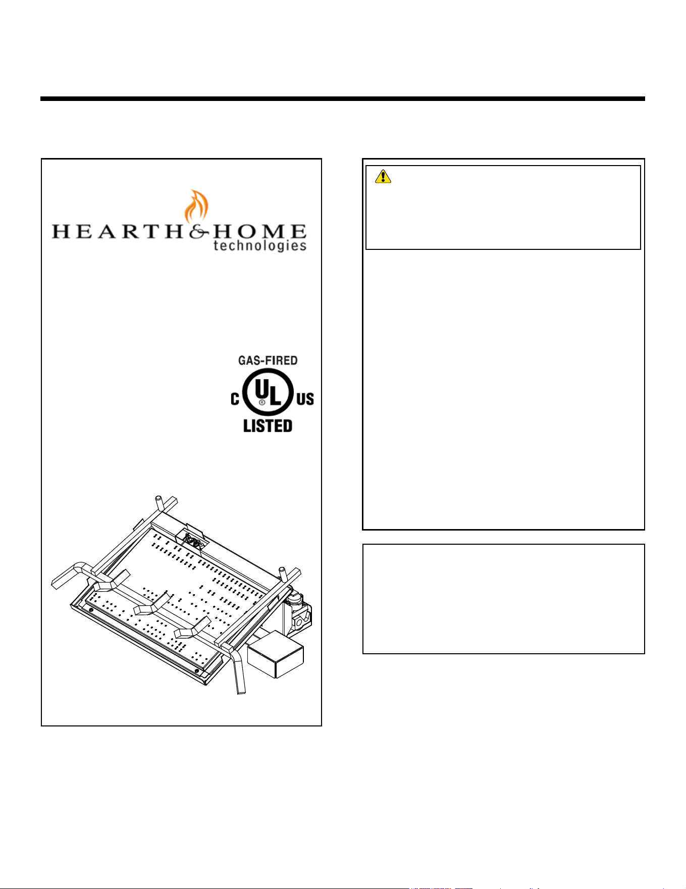
Model(s):
RB-18-24NI
RB-18-24PI
RB-30NI
RB-30PI
Duzy Series
Vented Gas Log Set
MH62954

Hearth & Home Technologies • Duzy Installation Manual • 4660-901 Rev. C • 06/242
Safety Alert Key:
• DANGER! Indicates a hazardous situation which, if not avoided will result in death or serious injury.
• WARNING! Indicates a hazardous situation which, if not avoided could result in death or serious injury.
• CAUTION! Indicates a hazardous situation which, if not avoided, could result in minor or moderate injury.
• NOTICE: Used to address practices not related to personal injury.
Table of Contents
► = Contains updated information
Installation Standard Work Checklist ....................3
1 Product Specic and Important Safety Information
A. Appliance Certication ............................4
B. BTU Specications and Weight .....................4
C. Gas Pressures ..................................4
D. High Altitude Installations ..........................4
E. Non-Combustible Materials Specication. . . . . . . . . . . . . . 4
F. Combustible Materials Specication .................4
G. California ......................................4
H. Requirements for the Commonwealth of Massachusetts . . 5
2 Getting Started
A. Design and Installation Considerations ...............6
B. Tools and Supplies Needed ........................6
C. Inspect Appliance and Components ..................6
D. Check Parts ....................................6
E. Minimum Hearth Dimensions ....................... 7
F. Installation Information ............................7
G. Restrictive Barriers ...............................8
H. Adequate Combustion Ventilation Air .................9
I. Negative Pressure ...............................9
3 Gas Information
A. Fuel Type ..................................... 10
B. Gas Pressure .................................. 10
C. Gas Connection ................................10
D. Verify Gas Pressure ............................. 11
E. Air Shutter Setting .............................. 11
4 Electrical Information
A. Wiring Requirements ............................12
5 Appliance Installation and Set-up
A. Position and Secure Appliance .................... 13
B. Install Component Covers ........................13
C. Install Switch and Remote Control ..................14
D. Install Grate ...................................14
E. Media Placement ...............................14
F. Log Placement .................................14
G. Flame Appearance ..............................15
H. Operating Instructions ...........................15
6 Reference Materials
A. Accessories ...................................16
3
Hearth & Home Technologies • Duzy Installation Manual • 4660-901 Rev. C • 06/24
Installation Standard Work Checklist
4660-982B 05/24
ATTENTION INSTALLER:
Follow this Standard Work Checklist
This standard work checklist is to be used by the installer in conjunction with, not instead of, the instructions contained in
this installation manual.
Customer:
Lot/Address:
Model (circle one):
Date Installed:
Location of Fireplace:
Installer:
Dealer/Distributor Phone #:
Serial #:
WARNING! Risk of Fire or Explosion! Failure to install appliance according to these instructions
could lead to a re or explosion.
Gas Log Install Sections 2 and 5
• Minimum rebox dimensions met
• Fireplace chimney has been cleaned
• Damper stop properly installed
• Veri ed adequate combustion ventilation air
• Appliance properly positioned and secured
Gas Section 3
• Proper appliance for fuel type
• Veri ed inlet and oulet pressures
• Leak check performed
• Veri ed proper air shutter setting for fuel type
Electrical Section 4
• Veri ed switch wires and/or remote control properly installed
Media & Logs Section 5
• Veri ed packaging and protective materials removed
• Media and logs installed correctly
• Veri ed ame appearance
Finishing
• Veri ed mantels and wall projections comply with replace
installation manual requirements.
• Manual bag and contents given to party responsible for use
and operation.
YES IF NO, WHY?
Hearth & Home Technologies recommends the following:
• Photographing the installation and copying this checklist for your le.
• That this checklist remain visible at all times on the appliance until the installation is complete.
Comments: Further description of the issues, who is responsible (Installer/ Builder/ Other Trades, etc) and corrective
action needed:
Comments communicated to party responsible: By: On:
(Builder / General Contractor) (Installer) (Date)
RB-18-24NI; RB-18-24PI;
RB-30NI; RB-30PI
Hearth & Home Technologies • Duzy Installation Manual • 4660-901 Rev. C • 06/244
1 1
Product Specic and Important Safety Information
This product is listed to ANSI standards for "Vented Gas
Log Sets” and applicable sections of "Gas Burning Heat-
ing Appliances for Manufactured Homes" and "Gas Fired
Appliances for Use at High Altitude."
A. Appliance Certication
E. Non-Combustible Materials Specication
Material which will not ignite and burn. Such materials are
those consisting entirely of steel, iron, brick, tile, concrete,
slate, glass or plasters, or any combination thereof.
Materials that are reported as passing ASTM E 136,
Standard Test Method for Behavior of Materials in
a Vertical Tube Furnace at 750 ºC shall be considered
non-combustible materials.
NOT INTENDED FOR USE AS A PRIMARY HEAT
SOURCE. This appliance is tested and approved as
either supplemental room heater or as a decorative ap-
pliance. It should not be factored as primary heat in
residential heating calculations.
NOTICE: This installation must conform with local codes.
In the absence of local codes you must comply with the
National Fuel Gas Code, ANSI Z223.1-latest edition in
the U.S.A.
B. BTU Specications and Weight
D. High Altitude Installations
NOTICE: If the heating value of the gas has been reduced,
these rules do not apply. Check with your local gas utility
or authorities having jurisdiction.
When installing above 2000 feet elevation:
• In the USA: Reduce input rate 4% for each 1000 feet
above 2000 feet.
• In CANADA: Input ratings are certied without a
reduction of input rate for elevations up to 4500
feet (1370 m) above sea level. Please consult
provincial and/ or local authorities having jurisdiction
for installations atelevations above 4500 feet (1370
m).Check with your local gas utility to determine
proper orice size.
Check with your local gas utility to determine proper
orice size
MODEL:
LABORATORY: Underwriters Laboratories (UL)
TYPE:
STANDARD:
NATURAL GAS: An external regulator is required to reduce
supply pressure to a maximum of 10.0” wc on natural gas
systems operating at higher pressure.
PROPANE/LP: An external regulator is required to reduce
supply pressure to a maximum of 13.0" wc
C. Gas Pressures
RB-18-24NI, RB-18-24PI,
RB-30NI, RB-30PI
ANSI Z21.60-2017 • CSA 2.26-2017
Decorative gas appliances for
installation in solid-fuel burning
replaces
Vented Gas Log Set
Models
Maximum
Input
(BTU/hr)
Main
Burner
Orice
Weight
(lbs.)
RB-18-24NI (0-2000 FT) 50,000 .144 in. (3.7 mm) 31
RB-18-24PI (0-2000 FT) 50,000 .086 in. (2.2 mm) 31
RB-30NI (0-2000 FT) 65,000 .161 in. (4.1 mm) 36
RB-30PI (0-2000 FT) 65,000 .098 in. (2.5 mm) 36
F. Combustible Materials Specication
Materials made of or surfaced with wood, compressed
paper, plant bers, plastics, or other material that can
ignite and burn, whether ame proofed or not, or plastered
or unplastered shall be considered combustible materials.
G. California
WARNING!
This product and the fuels used to
operate this product (liquid propane or natural gas), and
the products of combustion of such fuels, can expose
you to chemicals including benzene, which is known to
the State of California to cause cancer and reproductive
harm. For more information go to: www.P65Warnings.
ca.gov.
Natural Propane (LP)
Inlet Minimum 5.0” wc 11.0” wc
Inlet Maximum 10.0” wc 13.0” wc
Manifold Pressure 3.5” wc 10.0” wc

5
Hearth & Home Technologies • Duzy Installation Manual • 4660-901 Rev. C • 06/24
H. Requirements for the Commonwealth of
Massachusetts
For all side wall horizontally vented gas fueled equipment
installed in every dwelling, building or structure used in
whole or in part for residential purposes, including those
owned or operated by the Commonwealth and where the
side wall exhaust vent termination is less than seven (7)
feet above nished grade in the area of the venting, in-
cluding but not limited to decks and porches, the following
requirements shall be satised:
Installation of Carbon Monoxide Detectors
At the time of installation of the side wall horizontal vented
gas fueled equipment, the installing plumber or gas tter
shall observe that a hard wired carbon monoxide detector
with an alarm and battery back-up is installed on the oor
level where the gas equipment is to be installed. In addi-
tion, the installing plumber or gas tter shall observe that
a battery operated or hard wired carbon monoxide detec-
tor with an alarm is installed on each additional level of
the dwelling, building or structure served by the side wall
horizontal vented gas fueled equipment. It shall be the
responsibility of the property owner to secure the services
of qualied licensed professionals for the installation of
hard wired carbon monoxide detectors.
In the event that the side wall horizontally vented gas fu-
eled equipment is installed in a crawl space or an attic,
the hard wired carbon monoxide detector with alarm and
battery back-up may be installed on the next adjacent
oor level.
In the event that the requirements of this subdivision can
not be met at the time of completion of installation, the
owner shall have a period of thirty (30) days to comply
with the above requirements; provided, however, that dur-
ing said thirty (30) day period, a battery operated carbon
monoxide detector with an alarm shall be installed.
Approved Carbon Monoxide Detectors
Each carbon monoxide detector as required in accor-
dance with the above provisions shall comply with NFPA
720 and be ANSI/UL 2034 listed and IAS certied.
Signage
A metal or plastic identication plate shall be permanent-
ly mounted to the exterior of the building at a minimum
height of eight (8) feet above grade directly in line with the
exhaust vent terminal for the horizontally vented gas fu-
eled heating appliance or equipment. The sign shall read,
in print size no less than one-half (1/2) in. in size, “GAS
VENT DIRECTLY BELOW. KEEP CLEAR OF ALL OB-
STRUCTIONS”.
Inspection
The state or local gas inspector of the side wall horizon-
tally vented gas fueled equipment shall not approve the
installation unless, upon inspection, the inspector ob-
serves carbon monoxide detectors and signage installed
in accordance with the provisions of 248 CMR 5.08(2)(a)1
through 4.
Exemptions
The following equipment is exempt from 248 CMR 5.08(2)
(a)1 through 4:
• The equipment listed in Chapter 10 entitled “Equipment
Not Required To Be Vented” in the most current edition
of NFPA 54 as adopted by the Board; and
• Product Approved side wall horizontally vented gas fu-
eled equipment installed in a room or structure separate
from the dwelling, building or structure used in whole or
in part for residential purposes.
MANUFACTURER REQUIREMENTS
Gas Equipment Venting System Provided
When the manufacturer of Product Approved side wall
horizontally vented gas equipment provides a venting
system design or venting system components with the
equipment, the instructions provided by the manufacturer
for installation of the equipment and the venting system
shall include:
• Detailed instructions for the installation of the venting
system design or the venting system components; and
• A complete parts list for the venting system design or
venting system.
Gas Equipment Venting System NOT Provided
When the manufacturer of a Product Approved side wall
horizontally vented gas fueled equipment does not pro-
vide the parts for venting the ue gases, but identies
“special venting systems”, the following requirements
shall be satised by the manufacturer:
• The referenced “special venting system” instructions
shall be included with the appliance or equipment in-
stallation instructions; and
• The “special venting systems” shall be Product Ap-
proved by the Board, and the instructions for that sys-
tem shall include a parts list and detailed installation
instructions.
A copy of all installation instructions for all Product Ap-
proved side wall horizontally vented gas fueled equip-
ment, all venting instructions, all parts lists for venting
instructions, and/or all venting design instructions shall
remain with the appliance or equipment at the completion
of the installation.
See Gas Connection section for additional Common-
wealth of Massachusetts requirements.
Note: The following requirements reference various
Massachusetts and national codes not contained in
this document.
Hearth & Home Technologies • Duzy Installation Manual • 4660-901 Rev. C • 06/246
2 2
Getting Started
A. Design and Installation Considerations
Installation MUST comply with local, regional, state and
national codes and regulations. Consult insurance carrier,
local building inspector, re ocials or authorities having
jurisdiction over restrictions, installation inspection and
permits.
Before installing, determine the following:
• Where burner assembly and log set are to be installed.
• Gas supply piping.
• Whether optional accessories, devices such as a wall
switch or remote control are desired.
• Approved wood burning masonry replace.
Improper installation, adjustment, alteration, service or
maintenance can cause injury or property damage. For
assistance or additional information, consult a qualied
service technician, service agency or your dealer.
B. Tools and Supplies Needed
Before beginning the installation be sure that the following
tools and building supplies are available.
• Tape measure
• Gloves
• Voltmeter
• Manometer
• Phillips screwdriver
• Safety glasses
• Flat blade screwdriver
• Soapy water solution for gas leak testing
• Electric drill and bits (1/4 in. magnetic)
• External regulator (for propane/LP only & 1/2 psi
Natural gas system)
• Piping which complies with local codes
• Pipe sealant approved for use with propane/LP
(Resistant to sulfur compounds)
WARNING! Risk of Fire, Explosion or Electric
Shock! DO NOT use this appliance if any part has been
under water. Call a qualied service technician to inspect
the appliance and to replace any part of the control sys-
tem and/or gas control which has been under water.
• Manual shuto valve
• Sediment trap
• Tee joint
• Pipe wrench
Gloves are recommended when handling
refractory and logs to prevent skin irritation
from loose bers. Logs are fragile; handle with
care.
D. Check Parts
Verify contents to ensure you have received all parts. You
should have the following:
• Vented Gas Log Burner Assembly
• Grate Assembly
• On/O Switch and Wire Harness
• RCB Remote Control
• (2) Bags of Lava Rock & (1) Bag Rock Wool
• Owner’s and Installation Instructions
• Valve and Ignition Covers (Flat)
• Fastener Pack w/ (2) Anchor Screws
• Flex Line & Pipe Fittings
• Damper Clamp
Installation and service of this appliance should be performed by
qualied personnel. Hearth & Home Technologies recommends
HHT Factory Trained or NFI certied professionals.
CAUTION
C. Inspect Appliance and Components
• Carefully remove the applaince and components from
the packaging.
• Attached to the appliance are tags identifying the
manufacturer, serial number, model number. Including
log set size, BTU/hr ratings and gas type.
• Review the attached tags before proceeding. Ensure
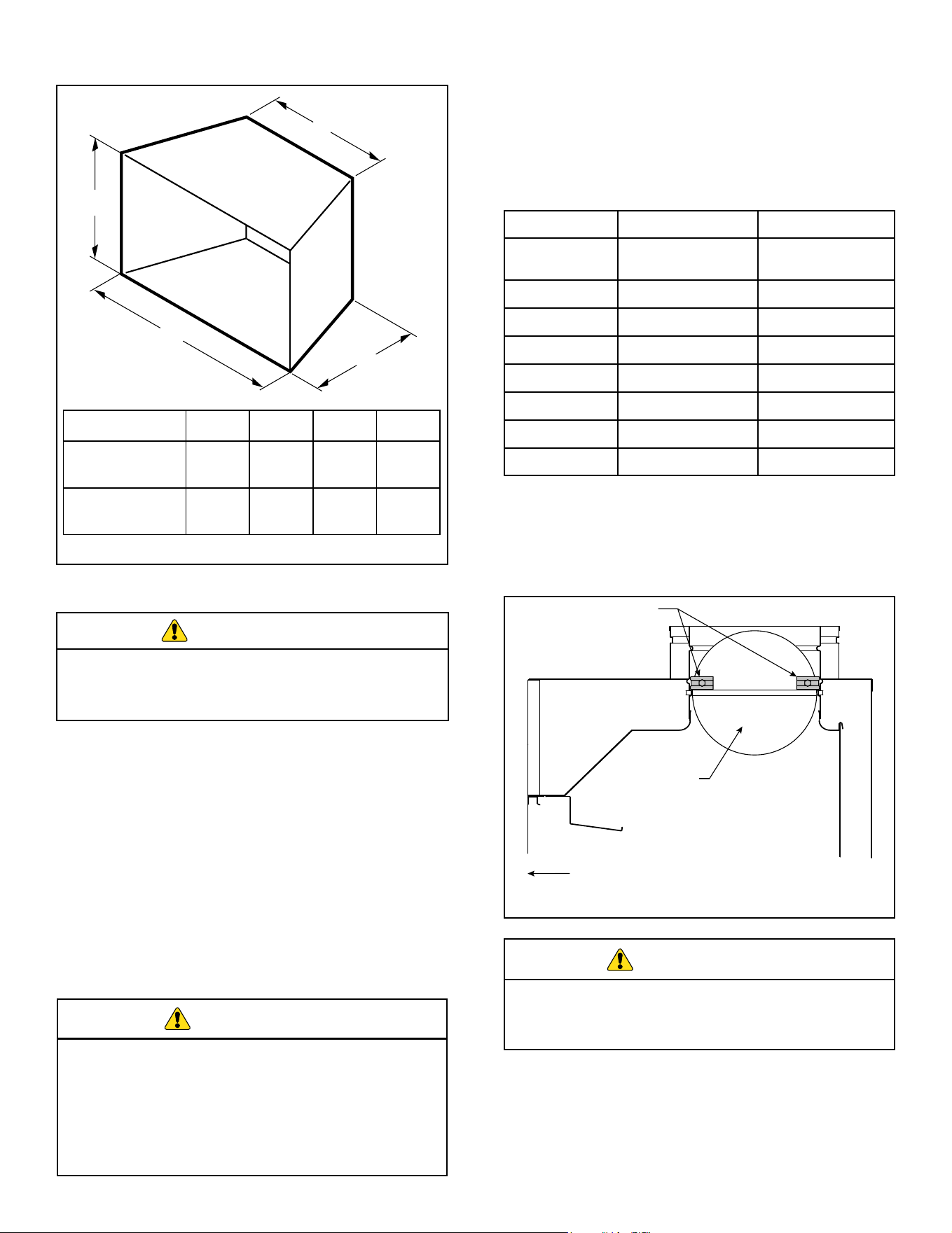
that all minimum replace dimension requirements are
achieved using Figure 2.1.
• Ensure the gas type provided in the replace coincide
with the gas type marked on the tag.
• Logs are packaged and sold separately.
• Report to your dealer any parts damaged in shipment.
• Read all of the instructions before starting the instal-
lation. Follow these instructions carefully during the
installation process to ensure maximum safety and
benet.
WARNING! Risk of Fire or Explosion! Damaged
parts could impair safe operation. DO NOT install dam-
aged, incomplete or substitute components. Keep appli-
ance dry.
Hearth & Home Technologies disclaims any responsi-
bility for, and the warranty will be voided by, the follow-
ing actions:
• Installation and use of any damaged appliance.
• Modication of the appliance.
• Installation other than as instructed by Hearth &
Home Technologies.
• Installation and/or use of any component part not
approved by Hearth & Home Technologies.
Any such action may cause a re hazard
7
Hearth & Home Technologies • Duzy Installation Manual • 4660-901 Rev. C • 06/24
A
C
D
B
F. Installation Information
Note: Use manufacturer's installation and clearance
requirements as dened in their manual.
This appliance is for installation only in a solid-fuel
burning masonry or UL127 factory-built replace.
It has been design certied for these installations.
Model A B C D
RB-18-24NI
RB-18-24PI
28.00”
(711 mm)
13.50”
(343 mm)
18.50”
(470 mm)
16.00”
(406 mm)
RB-30NI
RB-30PI
34.00”
(864 mm)
13.50”
(343 mm)
24.50”
(622 mm)
16.00”
(406 mm)
Figure 2.1 Minimum Hearth Dimensions
E. Minimum Hearth Dimensions
Do not install the applaince:
• Where curtains, furniture, clothing, or
other ammable objects are less than 36"
from the front of the heater.
• In high trac areas.
• In windy or drafty areas.
BEFORE INSTALLING THE APPLIANCE:
• Turn o gas supply to Masonry replace or manufac-
tured wood burning rebox.
• Have the replace oor and chimney professionally
cleaned to remove ash, soot, creosote or other ob-
structions. Have this cleaning performed annually af-
ter installation.
• Seal any fresh air vents or ash clean-out doors lo-
cated on oor or wall of replace. If not, drafting may
cause pilot outage or sooting. Use a heat-resistant
sealant.
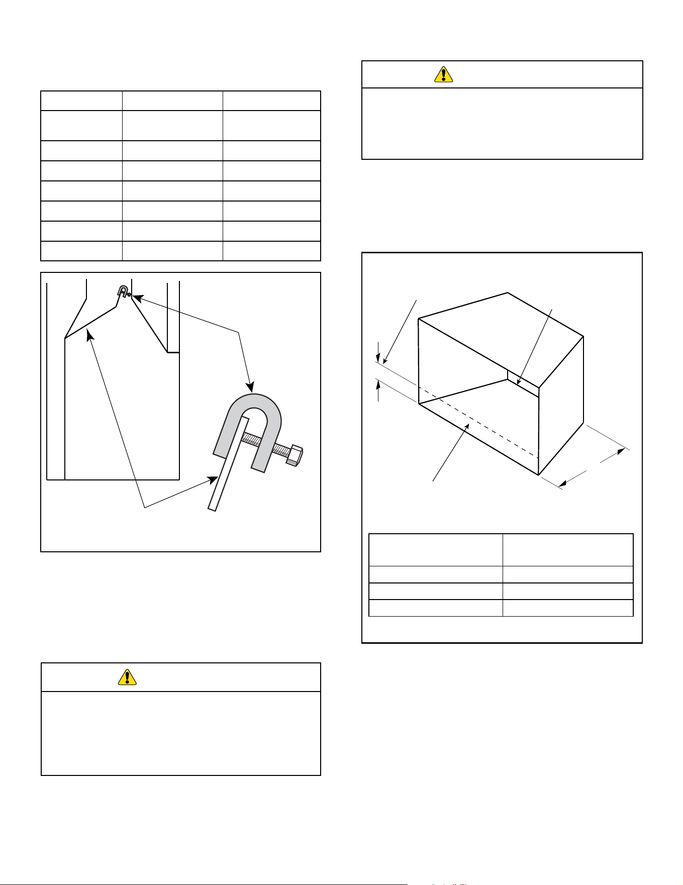
Damper Stop Installation
A damper stop is provided with this appliance. The damp-
er stop MUST be installed to prevent full closure of the
replace damper blade and provide a minimum ue open-
ing, per tables below.
WARNING
WARNING
Note: Should the stop not t, or provide the required per-
manent opening from the table have the damper blade
cut to provide minimum permanent opening or a perma-
nent stop installed.
WARNING
RB-18-24NI / PI RB-30NI / PI
Chimney Height
(feet)
Minimum Opening
(in
2
)
Minimum Opening
(in
2
)
10 28.3 44.2
15 21.2 32.2
20 18.1 26.4
25 15.9 22.9
30 14.5 20.4
35 13.2 18.9
40 12.6 18.1
Free opening area of chimney damper for venting
combustion products (factory-built replaces)
Improper installation or use of the appliance can
cause serious injury or death from fire, burns,
explosion or carbon monoxide poisoning.
Recommended
Damper Stop
Location
Damper
Blade
Front of Fireplace
Figure 2.2 Factory Built Fireplace Example
Factory Built Fireplace: Position damper stop on the top
half of the damper blade, slide stop towards the center
of the damper blade to create an interferance with the
bead on the ue collar and tighten bolt. Either side of the
damper blade is acceptable. See Figure 2.2.
Hearth & Home Technologies • Duzy Installation Manual • 4660-901 Rev. C • 06/248
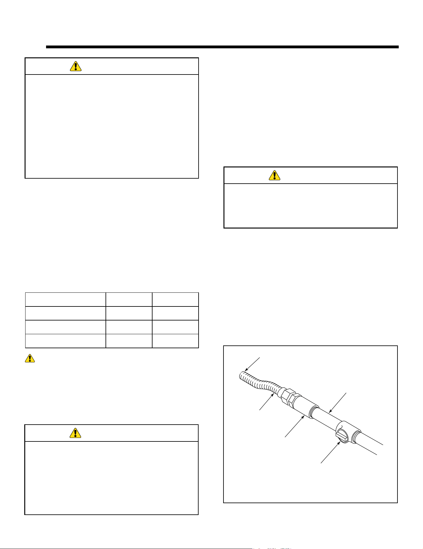
The following are guidelines for placing a gas log set in a
replace that has a restrictive barrier on the replace for
vented appliance only. See Figure 2.4.
*Any barrier greater than 3" placed in front of the gas log
set is not recommended by the manufacturer.
G. Restrictive Barriers
Barriers such as the bottom of a glass door frame
placed in front of a gas log set can change the air ow
characteristics of the replace, which in turn can
cause the applaince to overheat and manfunction
when installed as a vented log set.
Figure 2.4 Restrictive Barriers
X
Y
Height of restrictive barrier caused
by glass door frames, recessed
fireplaces, etc. from the base or
bottom surface of the unit.
Glass door frames with adjustable
louvers should have the louvers
fully open while the unit is in
operation.
The log set should
be placed against or
as near as possible
to the rear wall of the
fireplace/firebox.
Height of Restriction
(X)
Minimum Depth of
Fireplace (Y)
No Restriction 13.50”
0” to 3” Restriction 15.00”
Greater than 3” Restriction *
NOTE: Non-combustible material such as refractory brick
may be used to line the oor of the replace in order to
raise the height of the gas log set in relation to a restrictive
barrier. If the appliance is raised, the minimum height
dimension listed in the homeowner’s manual must be met
or exceeded.
NOTE: This log set is supplied with a remote receiver, a
restrictive barrier may reduce the battery life by increasing
the ambient temperature inside the replace.
WARNING
For Massachusetts Residents Only
Installation of this vented gas log set in the Common-
wealth of Massachusetts requires the damper be perma-
nently removed or welded in the fully open position. In
addition, a naturally vented gas log may not be installed
in a bedroom or bathroom in the Commonwealth of Mas-
sachusetts.
WARNING
The replace and gas logs function as a system. If
the replace is spilling into the room (check with
a match or smoke stick), reposition the damper
clamp until a positive draft is obtained, by opening
the damper. If negative pressure in the home pre-
vents having a positive draft contact your dealer.
Damper Stop Installation (cont.)
FP2727
damper
Damper
Stop
Damper
Blade
Figure 2.2 Masonary Fireplace Example
Free opening area of chimney damper for venting
combustion products (masonry-built replaces)
RB-18-24NI / PI RB-30NI / PI
Chimney Height
(feet)
Minimum Opening
(in
2
)
Minimum Opening
(in
2
)
6 41.7 56.6
8 38.7 52.4
10 35.2 48.2
15 32.0 43.2
20 28.8 39.8
30 26.5 35.9

9
Hearth & Home Technologies • Duzy Installation Manual • 4660-901 Rev. C • 06/24
H. Adequate Combustion Ventilation Air
This appliance shall not be installed in a conned space or
unusually tight construction unless provisions are provided
for adequate combustion and ventilation air.
The National Fuel Gas Code, (ANSI Z223.1/NFPA54),
denes a conned space as a space whose volume is less
than 50 cubic feet per 1,000 BTU per hour (4.8m
3
per kw)
of the aggregate input rating of all appliances installed in
that space. Rooms communicating directly with the space
in which the appliances are installed, through openings not
furnished with doors, are considered a part of a conned
space.
If the area in which the appliance may be
operated does not meet the required volume
for indoor combustion air, combustion and
ventilation air shall be provided by one of the
methods described in the National Fuel Gas
Code, ANSI Z223.1/NFPA 54, the International
Fuel Gas Code or applicable local codes.
WARNING
I. Negative Pressure
Negative pressure results from the imbalance of air avail-
able for the replace to operate properly. Possible causes
for this imbalance include:
• Exhaust fans (kitchen, bath, etc.)
• Range hoods
• Combustion air requirements for furnaces, water heat-
ers and other combustion appliances
• Clothes dryers
• Location of return-air vents to furnace or air condition-
ing
• Imbalances of the HVAC air handling system
• Upper level air leaks: recessed lighting, attic hatch
opening, duct leaks.
Hearth & Home Technologies • Duzy Installation Manual • 4660-901 Rev. C • 06/2410
3 3
Gas Information
Use new black iron or steel pipe. Internally tinned
copper or copper tubing can be used per National
Fuel Code, section 2.6.3, providing gas meets
hydrogen sulde limits, and where permitted by local
codes. Gas piping system must be sized to provide
minimum inlet pressure (Listed on Data Plate) at the
maximum ow rate (BTU/hr). Undue pressure loss
will occur if the pipe is too small.
A manual shuto valve must be installed upstream
of the appliance. Union tee and plugged 1/8” NPT
pressure tapping point should be installed upstream
of the appliance.
WARNING
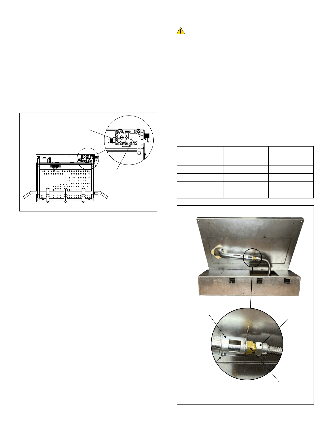
C. Gas Connection
The gas inlet connection is on the right rear side of the
appliance. To connect from the opposite side, route the
inlet pipe and appliance gas connector around the back
of the appliance.
IMPORTANT: When tightening up the joint to the valve,
hold the valve securely to prevent movement.
Test all gas joints from the gas meter to the appliance
valve for leaks using a gas analyzer or soap and water
solution after completing connection. DO NOT USE AN
OPEN FLAME. Check the gas pressure with the appli-
ance burning.
Fire Risk!
Explosion Hazard!
High pressure will damage valve!
• Disconnect gas supply piping BEFORE pressure
testing gas line at test pressures above 1/2 psig.
• Close the manual shuto valve BEFORE pres-
sure testing gas line at test pressures equal to
or less than 1/2 psig.
WARNING
Manual
Shutoff Valve
Coupling
To Control Valve
Stainless
Flexline
Gas Supply
Line
Figure 3.1 Gas Connection
A. Fuel Type
The gas supply must be the same as stated on the appli-
ance rating plate. If the gas supply is dierent, DO NOT
INSTALL THE APPLIANCE. Contact your dealer for the
correct model.
B. Gas Pressure
• Optimum appliance performance requires proper in-
put pressures.
• Gas line sizing requirements will be determined in
ANSI Z223.1 National Fuel Gas Code in the USA.
• Pressure requirements are:
WARNING! Risk of Fire or Explosion! High
pressure will damage valve. Low pressure could cause
explosion.
• Verify inlet pressures. Verify minimum pressures
when other household gas appliances are operating.
• Install regulator upstream of valve if line pressure is
greater than 1/2 psig.
CHECK GAS TYPE: The gas supply must be the
same as stated on the appliance rating plate. If the
gas supply is dierent, DO NOT INSTALL THE
APPLIANCE. Contact your dealer for the correct
model.
WARNING
Note: Have the gas supply line installed in accordance
with local codes, if any. If not, follow ANSI Z223.1. Instal-
lation should be done by a qualied installer approved
and/or licensed as required by the locality (In the Com-
monwealth of Massachusetts installation must be per-
formed by a licensed plumber or gas tter).
Note: A listed (and Commonwealth of Massachusetts ap-
proved) 1/2 in. (13 mm) T-handle manual shut-o valve
must be installed upstream of the appliance.
IMPORTANT: Install manual shuto valve in an acces-
sible location. The manual shuto valve is for turning on
or shutting o the gas to the appliance.
Natural Propane (LP)
Inlet Minimum 5.0” wc 11.0” wc
Inlet Maximum 10.0” wc 13.0” wc
Manifold Pressure 3.5” wc 10.0” wc
11
Hearth & Home Technologies • Duzy Installation Manual • 4660-901 Rev. C • 06/24
Burner Bottom View
Flex Line
Burner
Air Shutter
Main Burner
Orifice
Air Shutter
Adjustment
Screw
D. Verify Gas Pressure
The valve regulator controls the burner pressure. Gas
pressure must be veried at both the inlet and outlet
pressure test ports.
1. Turn captured screw counterclockwise two or three
turns. See Figure 3.2.
2. Place tubing from pressure gauge over test port.
3. After taking pressure readings, be sure and turn
captured screw clockwise rmly to re-seal. Do not
over torque.
4. Check for gas leaks.
Figure 3.2 Valve Pressure Port Locations
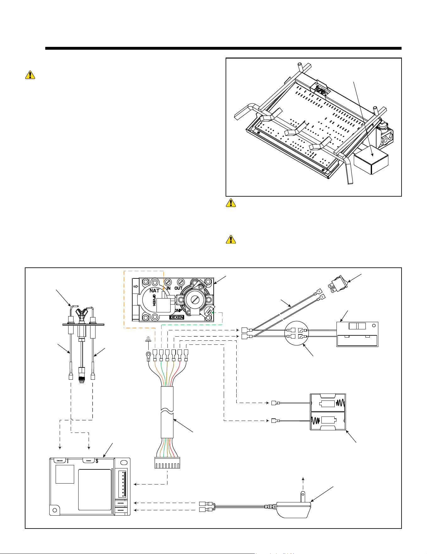
E. Air Shutter Setting
WARNING! Risk of Explosion or Delayed Ignition!
Improperly adjusted air shutter may cause excessive
soot buildup.
NOTICE: If excessive sooting occurs, provide more air
by opening the air shutter.
The air shutter is preset at the factory. Settings should be
veried/adjusted by a qualied service technician at the
time of installation. See Figure 3.3.
To adjust air shutter settings:
1. Carefully stand the Burner Assembly to gain access
to the burner bottom.
2. Loosen air shutter adjustment screw.
3. Rotate air shutter to appropriate postion.
4. Tighten air shutter set adjustment screw.
Figure 3.3 Air Shutter Adjustment
MODEL FUEL TYPE AIR SHUTTER
RB-18-24NI Natural Gas 5/16”
RB-18-24PI Propane Fully Open
RB-30NI Natural Gas 5/16”
RB-30PI Propane Fully Open
Inlet
Pressure
Port
Outlet
Pressure
Port
Hearth & Home Technologies • Duzy Installation Manual • 4660-901 Rev. C • 06/2412
4 4
Electrical Information
A. Wiring Requirements
WARNING! Risk of Shock or Explosion! DO NOT
wire 110-120 VAC to the valve. Incorrect wiring will dam-
age controls.
• The intermittent pilot ignition system (IPI) on the Duzy
series gas log set comes standard with an integrated
battery pack, that holds (2) D size batteries. See Fig-
ure 4.1.
• The appliance does NOT require 110 VAC for opera-
tion. If the vented replace/rebox the appliance is
installed in is electrically wired, it must be wired and
grounded in accordance with local codes or, in the
absence of local codes, with National Electric Code
ANSI/NFPA 70-latest edition.
• An ON/OFF switch is provided as part of the Remote
Control supplied with the appliance.
• The Remote Control can be incorporated into this
system by connecting the remote or wall switch wires
to the appliance switch wires as shown. See Figure
4.2.
NOTE: The use of a thermostat is prohibited in vented
log installations.
I
S
PILOT
F F
F F
F F
ON RS OFF
M
M
M
M
M
F
M
F
WHITE
ORANGE
CONTROL
MODULE
GAS VALVE
3V ADAPTER
(OPTIONAL)
TO
110 VAC
BATTERY
PACK
HEAT SHRINK
THESE (2)
CONNECTIONS
WIRE
HARNESS
REMOTE
CONTROL
ON/OFF
SWITCH
WIRE HARNESS:
BLACK = GROUND
ORANGE = VALVE
GREEN = VALVE
BROWN = SWITCH
BLACK = BATTERY (-)
RED = BATTERY (+)
Battery Pack
Figure 4.1 Battery Pack Location
Figure 4.2 IPI Wiring Diagram
WARNING! Risk of Shock! Label all wires prior to
disconnection when servicing controls. Wiring errors can
cause improper and dangerous operation. Verify proper
operation after servicing.
WARNING! Risk of Shock! Replace damaged wire
with type 105º C rated wire. Wire must have high tem-
perature insulation.
13
Hearth & Home Technologies • Duzy Installation Manual • 4660-901 Rev. C • 06/24
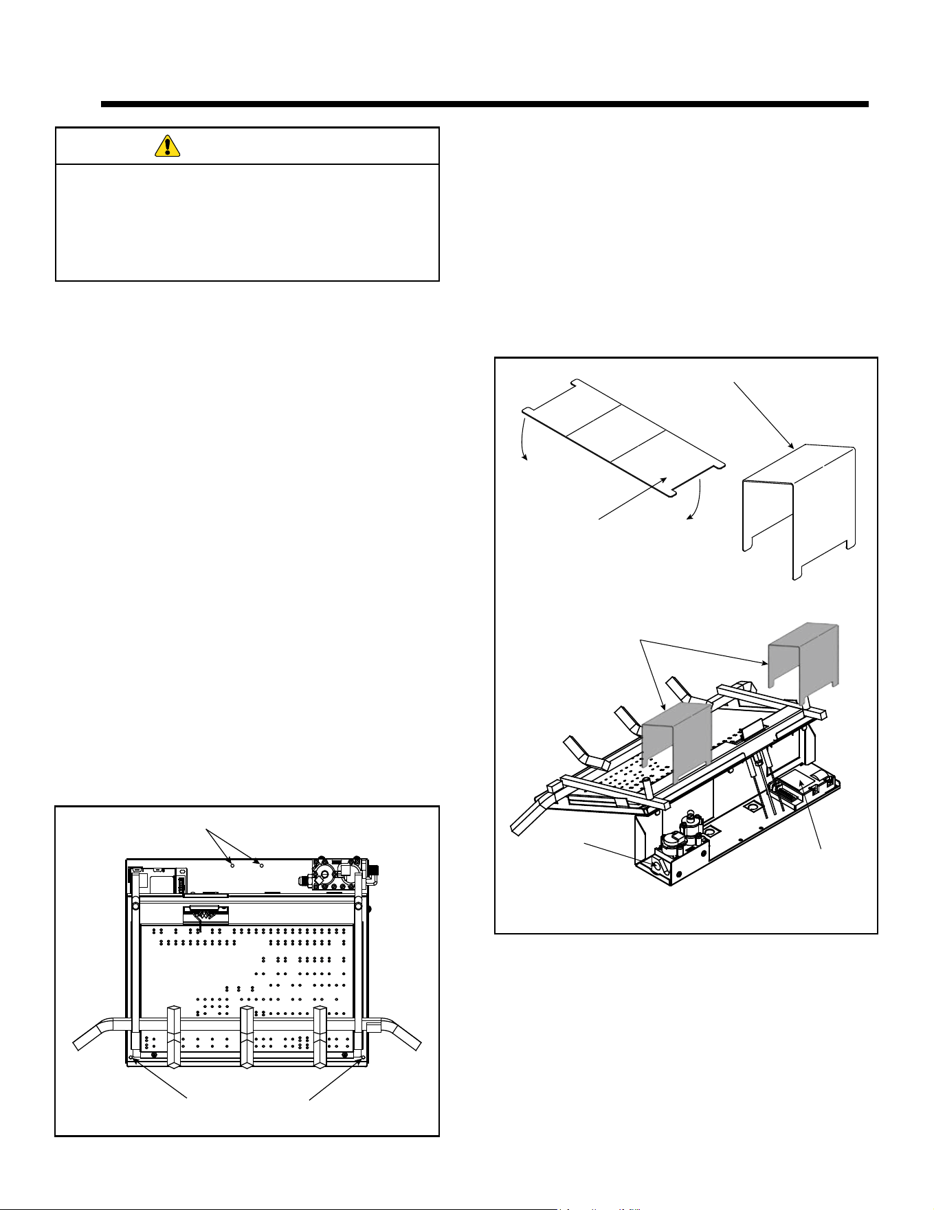
Gas
Valve
Ignition
Control
Covers
Mounting Holes
Mounting Holes
(Alt. Loc.)
5 5
Appliance Installation and Set-up
A. Position and Secure Appliance
The appliance is assembled with the gas controls
installed at the factory, and is designed to connect the
3/8” supply line before making nal placement inside the
replace.
1. Place the appliance towards the rear and center of
the replace and connect the gas line.
2. Tighten incoming gas connection. Follow instructions
in section 3.C Gas Connection to check for gas
leaks.
3. Center the gas log appliance in the replace. Make
certain the front feet of the grate sit inside the front
edge of the replace.
4. Once the appliance is positioned correctly, side
to side and front to back, mark the mounting hole
positions on the replace oor. See Figure 5.1 for
mounting hole locations.
5. Drill (2) 5/32” diameter holes approximately 1-1/2”
deep.
6. Anchor the appliance to the replace oor using the
screws provided.
Note: Proper installation of the appliance is essential to
prevent movement of the gas logs and controls during
operation.
You must secure the gas log appliance to the
replace oor. If not, the entire unit may move when
you adjust the controls. Movement of unit may cause
shifting of the gas logs which leads to sooting and
improper burning. Grate movement could cause a
gas leak.
WARNING
Figure 5.1 Mounting Holes and Grate Installation
B. Install Component Covers
This appliance is shipped with two component covers.
These covers are designed to provide additional protection
for the appliance gas valve and ignition control module..
Note: The Valve Cover is shipped at and must be formed
prior to installation.
1. Form Covers as shown. See Figure 5.2.
2. Install Covers so that they cover the appliance gas
valve and ignition control module completely. See
Figure 5.2
Figure 5.2 Cover Installation
Cover (Flat)
Cover (Formed)
Hearth & Home Technologies • Duzy Installation Manual • 4660-901 Rev. C • 06/2414
The positioning of the grate and logs is critical to
the safe and clean operation of this appliance. Soot-
ing and other problems may result if the logs are
not properly and rmly positioned in the appliance.
Never add additional logs or embellishments such
as pine cones, vermiculite or rock wool to the ap-
pliance. Only use the logs and rock wool supplied
with the unit.
Failure to position the parts in accordance with dia-
grams on the following pages or failure to use only
parts specically approved for this appliance may
result in property damage or personal injury.
WARNING
D. Install Grate
This appliance is shipped with an integral grate that has
been designed to correctly position and support the gas
logs.
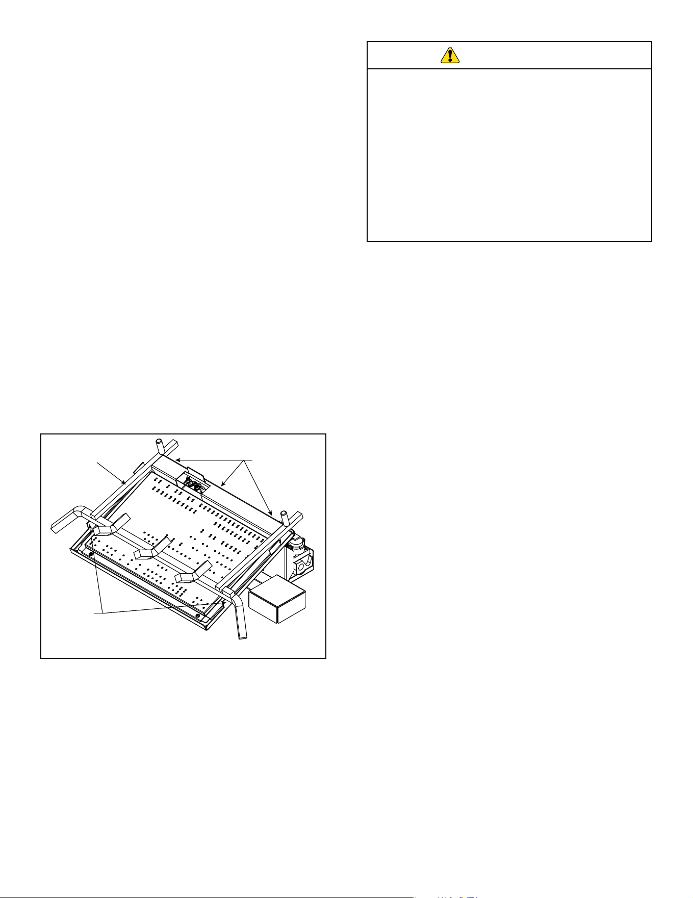
1. To properly position the grate, align the three tabs lo-
cated at the rear of the grate, with the three slots in
the rear of the burner base assembly. The front grate
bar should rest on the two support tabs located on the
side of the burner base assembly. This will position
the grate front to back and side to side. See Figure
5.1.
E. Media Placement
Glowing Embers:
Cover the entire top surface of the burner pan with
glowing embers (rock wool) provided. Tear pieces into
approximately 1/2” diameter pieces, roughly nickel size,
and cover the burner evenly.
DO NOT:
• Pile the glowing embers too heavily on the pan.
• Place glowing embers higher than the top of the
front grate bar.
• Cover the pilot with glowing embers
Decorative Volcanic Rock:
Spread decorative volcanic rock evenly in front of, and
on the left and right sides of the burner pan.
DO NOT:
• Place decorative volcanic rock on the burner, pilot or
logs.
C. Install Switch and Remote Control
The Duzy series vented log set comes supplied with an
On/O Switch and a battery powered remote control kit.
1. Connect the On/O Switch and Remote Receiver
to appliance brown switch wires using the included
wire harness as shown in Figure 4.2.
Note: Heat shrink tubing has been supplied and should
be used to isolate remote control receiver connectors
from accidental contact with conductive surfaces, which
may result in unintended appliance ignition.
2. Position the remote control receiver in a convenient
location, which allows for safe safe operation of
the appliance and replacement of batteries, as
necessary.
F. Log Placement
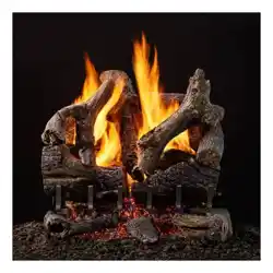
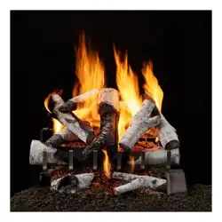
The Duzy series vented log set has multiple log options
to choose from. These logs are sold seperately and are
listed in Section 6 of this manual.
For log placement instructions refer to the iinstallation in-
structions supplied with the log set.
NOTE: The Duzy appliance is designed to be operated
with one of the optional log sets installed. Do NOT oper-
ate this appliance without a log set installed.
Grate
Assembly
Support
Tabs
Locator Tabs
Figure 5.3 Grate Placement
15
Hearth & Home Technologies • Duzy Installation Manual • 4660-901 Rev. C • 06/24
G. Flame Appearance
Flames from the pilot and burner should be visually
checked as soon as the appliance is installed. In addi-
tion, periodically check the ames visually during operation.
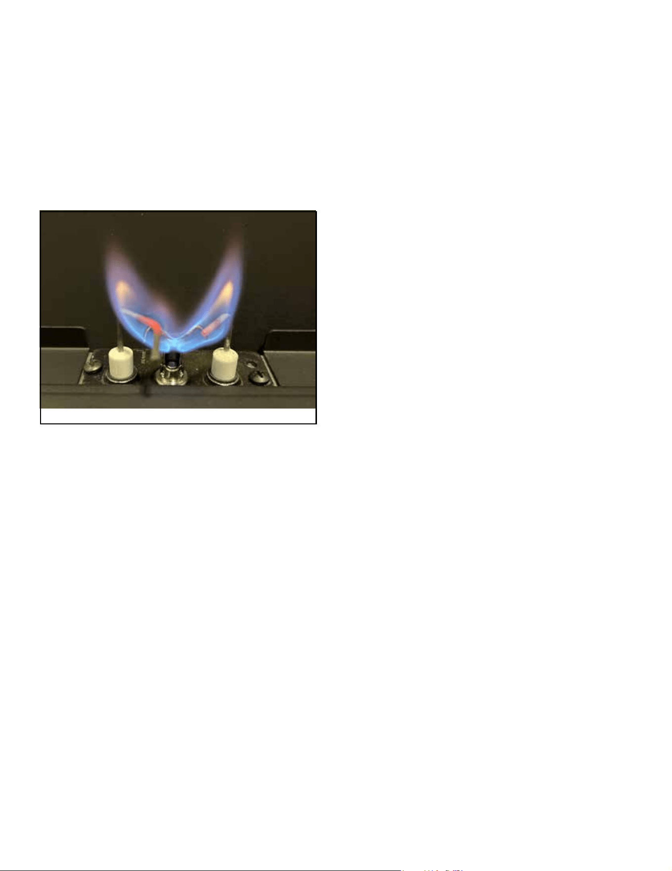
Pilot Flame:
The IPI pilot ame must always be present when the appli-
ance is in operation. Pilot ame should engulf the ame
sensor rod. See Figure 5.18.
If the pilot ame does not touch the ame sensor, then the
main burner cannot function reliably.
H. Operating Instructions
Avoid any drafts that alter burner ame patterns. Do not
allow fans to blow directly on the appliance. Do not place
a blower inside the burn area of the replace. Ceiling fans
may create drafts that alter ame patterns. Sooting and
improper burning will result.
During manufacturing, fabricating and shipping, various
components of this appliance are treated with certain oils,
lms or bonding agents. These chemicals are not harm-
ful, but may produce annoying smoke and smells as they
are burned o during the initial operation of the appliance,
possibly causing headaches or eye or lung irritation. This
is a normal and temporary occurrence.
The initial break-in operation should last four hours with the
burner at the highest setting. Provide maximum ventilation
by opening windows or doors to allow odors to dissipate.
Any odors remaining after this initial break-in will be slight
and will disappear with continued use.
This appliance must not be operated with glass doors
in the closed position.
Main Burner Flame:
Operate the appliance at full rate for 45 minutes, the fol-
lowing ame appearances should be observed.
Burner will have a random pattern of yellow ames, with
glowing embers covering the main burner.
Note: This appliance is a vented gas log set, therefore
some ame impingement and soot is normal.
Observe ames for excessive impingement with any of the
logs. If excessive impingement is present, turn o log set
and allow to cool. Remove all logs and carefully reinstall
following log placement instructions precisely. Relight
burner and check again for excessive impingement. If ame
impingement cannot be eliminated, contact your installer
or dealer for assistance.
Figure 5.18 IPI Pilot Flame

Hearth & Home Technologies • Duzy Installation Manual • 4660-901 Rev. C • 06/2416
6 6
Reference Materials
A. Accessories
Media
• DV-RWA Rock Wool, Carton of 12-4 oz. Bags
• VR1000A Volcanic Rock - Carton of 12 - 2 lb. Bags
Power Supply
• SRV593-593 3V Transformer
Remote Protective Cover
• RRCM Remote Receiver Cover Metal
Conversion Kits
• SRV4660-060 Natural Gas Conversion Kit for Duzy Series Appliance
• SRV4660-061 Propane Gas Conversion Kit for Duzy Series Appliance
Log Sets
• DUZY2LS-18-24 Ceramic Fiber Log Set for RB-18-24 Burners (4 Piece)
• DUZY2LS-30 Ceramic Fiber Log Set for RB-30 Burners (4 Piece)
• DUZY3LS-18-24 Refractory Cement Log Set for RB-18-24 Burners (6 Piece)
• DUZY3LS-30 Refractory Cement Log Set for RB-30 Burners (6 Piece)
• DUZY5LS-18-24 Ceramic Fiber Log Set for RB-18-24 Burners (8 Piece)
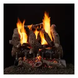
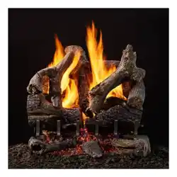
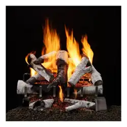
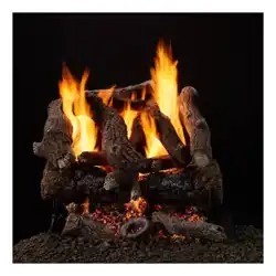
• DUZY5LS-30 Ceramic Fiber Log Set for RB-30 Burners (8 Piece)