© 2024
19001 Kermier Rd., Waller, TX 77484
www.daikincomfort.com
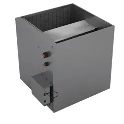
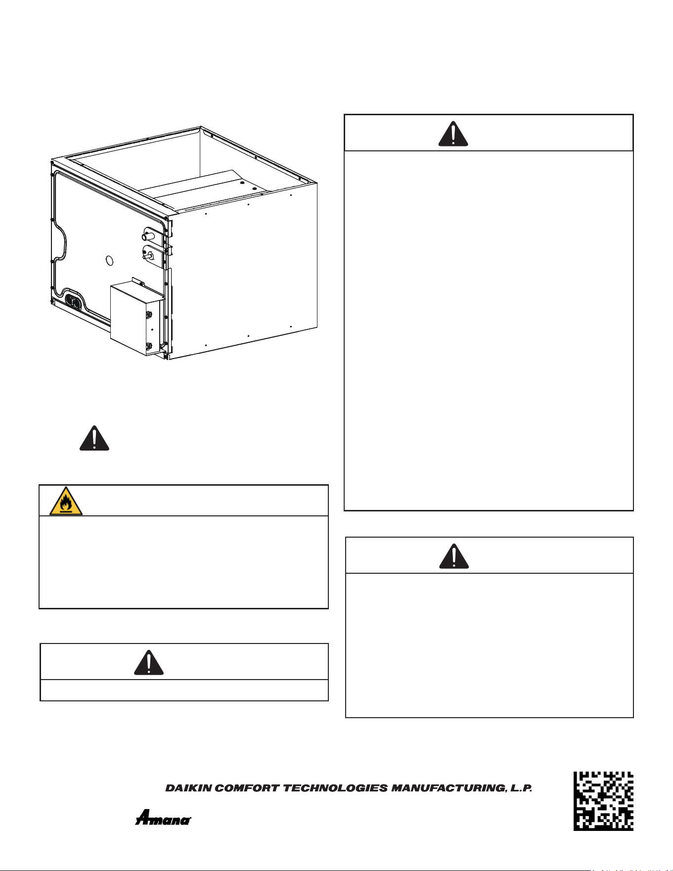
CAPEA SERIES
VERTICAL CASED COIL
INSTALLATION INSTRUCTIONS
RECOGNIZE THIS SYMBOL
AS A SAFETY PRECAUTION.
IO-460B
12/2024
Do not bypass safety devices.
WARNING
Our continuing commitment to quality products may mean a change in specications without notice
WARNING: FLAMMABLE MATERIALS
DO NOT USE MEANS TO ACCELERATE THE DEFROSTING
PROCESS OR TO CLEAN, OTHER THAN THOSE RECOMMENDED
BY THE MANUFACTURER. THE APPLIANCE SHALL BE STORED
IN A ROOM WITHOUT CONTINUOUSLY OPERATING IGNITION
SOURCES (FOR EXAMPLE: OPEN FLAMES, AN OPERATING
GAS APPLIANCE OR AN OPERATING ELECTRIC HEATER. DO
NOT PIERCE OR BURN. BE AWARE THAT REFRIGERANTS MAY
NOT CONTAIN AN ODOR.
ONLY PERSONNEL THAT HAVE BEEN TRAINED TO INSTALL,
ADJUST, SERVICE, MAINTENANCE OR REPAIR
(HEREINAFTER, “SERVICE”) THE EQUIPMENT SPECIFIED IN
THIS MANUAL SHOULD SERVICE THE EQUIPMENT.
THIS EQUIPMENT IS NOT INTENDED FOR USE BY
PERSONS (INCLUDING CHILDREN) WITH REDUCED
PHYSICAL, SENSORY OR MENTAL CAPABILITIES, OR LACK
OF EXPERIENCE AND KNOWLEDGE, UNLESS THEY HAVE
BEEN GIVEN SUPERVISION OR INSTRUCTION CONCERNING
USE OF THE APPLIANCE BY A PERSON RESPONSIBLE FOR
THEIR SAFETY.
CHILDREN SHOULD BE SUPERVISED TO ENSURE THAT
THEY DO NOT PLAY WITH THE EQUIPMENT.
THE MANUFACTURER WILL NOT BE RESPONSIBLE FOR
ANY INJURY OR PROPERTY DAMAGE ARISING FROM
IMPROPER SUPERVISION, SERVICE OR SERVICE
PROCEDURES. IF YOU SERVICE THIS UNIT, YOU ASSUME
RESPONSIBILITY FOR ANY INJURY OR PROPERTY
DAMAGE WHICH MAY RESULT. IN ADDITION, IN
JURISDICTIONS THAT REQUIRE ONE OR MORE LICENSES
TO SERVICE THE EQUIPMENT SPECIFIED IN THIS
MANUAL, ONLY LICENSED PERSONNEL SHOULD SERVICE
THE EQUIPMENT. IMPROPER SUPERVISION, INSTALLATION,
ADJUSTMENT, SERVICING, MAINTENANCE OR REPAIR OF
THE EQUIPMENT SPECIFIED IN THIS MANUAL, OR
ATTEMPTING TO INSTALL, ADJUST, SERVICE OR REPAIR
THE EQUIPMENT SPECIFIED IN THIS MANUAL WITHOUT
PROPER SUPERVISION OR TRAINING MAY RESULT IN
PRODUCT DAMAGE, PROPERTY DAMAGE, PERSONAL
INJURY OR DEATH.
WARNING
If any hot work is to be conducted on the refrigerating
equipment or any associated parts, appropriate fire
extinguishing equipment shall be available on hand. Have
a dry powder or CO2 fire extinguisher adjacent to the
charging area.
Ensure that the area is in the open or that it is
adequately ventilated before breaking into the system
or conducting any hot work. A degree of ventilation
shall continue during the period that the work is carried
out. The ventilation should safely disperse any released
refrigerant and preferably expel it externally into the
atmosphere.
WARNING
is a registered trademark of Maytag Corporaon or its related companies and is used under license. All rights reserved.
2
1 IMPORTANT SAFETY INSTRUCTIONS
The following symbols and labels are used throughout this
manual to indicate immediate or potential safety hazards. It is
the owner’s and installer’s responsibility to read and comply
with all safety information and instructions accompanying
these symbols. Failure to heed safety information increases
the risk of personal injury, property damage, and/or product
damage.
NOTICE: THIS PRODUCT CONTAINS ELECTRONIC
COMPONENTS WHICH REQUIRE A DEFINITE GROUND.
PROVISIONS ARE MADE FOR CONNECTION OF THE
GROUND. A DEDICATED GROUND FROM THE MAIN
POWER SUPPLY OR AN EARTH GROUND MUST BE
PROVIDED.
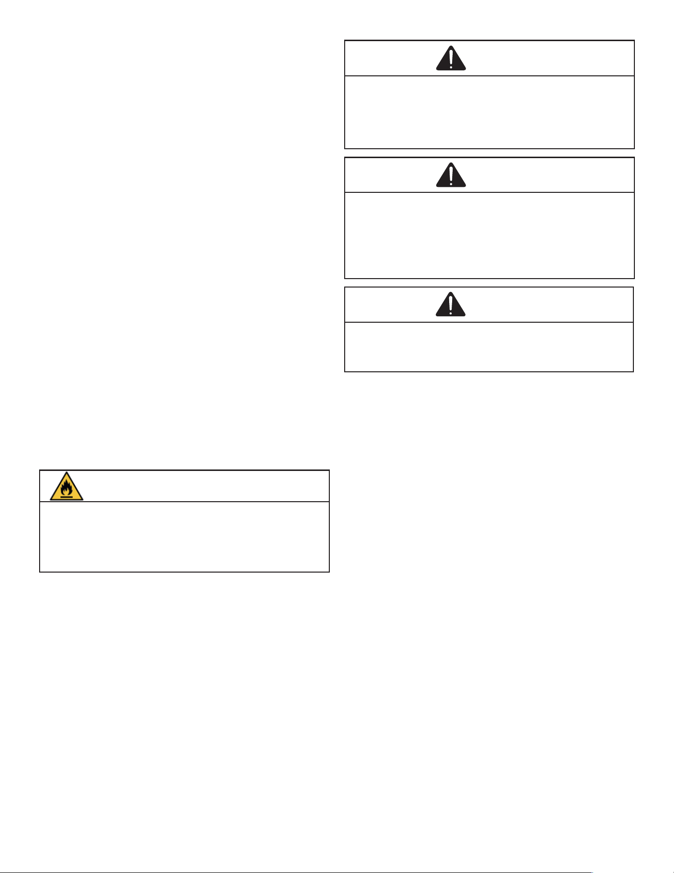
WARNING
HIGH VOLTAGE
Disconnect ALL power before servicing or
installing this unit. Multiple power sources
may be present. Failure to do so may cause
property damage, personal injury or death.
WARNING
To prevent the risk of property damage, personal injury, or
death, do not store combustible materials or use gasoline or
other flammable liquids or vapors in the vicinity of this unit.
WARNING
Do not connect to or use any device that is not certified by
the manufacturer for use with this unit. Serious property
damage, personal injury, reduced unit performance and/or
hazardous conditions may result from the use of such non-
approved devices.
TABLE OF CONTENTS
1 Important Safety Instructions ...........................................................2
2 Shipping Inspection ...........................................................................4
2.1 Parts ............................................................................................4
2.2 Handling ......................................................................................4
3 Codes & Regulations .........................................................................4
4 Replacement Parts.............................................................................4
5 Pre-Installation Considerations ........................................................4
5.1 Preparation ..................................................................................5
5.2 System Matches ..........................................................................6
5.3 Clearances ..................................................................................6
5.4 Access .........................................................................................6
6 Application Information ....................................................................6
6.1 Filler Plates ..................................................................................7
6.2 Insulation Kit ................................................................................7
6.3 Down Flow Kit (For CAPEA4830C, D & CAPEA6030C,D) ........8
7 Return Ductwork ................................................................................8
8 Refrigerant Piping Work ....................................................................8
8.1 Tubing Size/Length ......................................................................9
8.2 Cut O The Spin Closure ............................................................9
8.3 Disconnect Internal Control Wiring ............................................10
8.4 Connect Piping ..........................................................................10
8.5 Re-assemble the Coil and Controls ...........................................11
9 Sealing Along The Panel Gap .......................................................12
10 Drain Piping Work ..........................................................................12
11 Electrical Wiring Work ...................................................................14
11.1 General Instructions ................................................................14
11.2 Wiring Sizing ............................................................................15
11.3 Safety Device...........................................................................15
11.4 Transformer Installation ...........................................................15
11.5 How To Install The Transformer ...............................................15
11.5.1A Installation Bracket - “A” .....................................................16
11.5.1B Installation Bracket - “B” .....................................................16
11.6 Wiring Transformer and PCB ...................................................17
11.7 Sensor and Accessory Wiring ..................................................18
12 Fully Communicating System .......................................................19
12.1 Overview .................................................................................19
12.2 Wire Harness Instructions .......................................................19
12.3 Thermostat Wiring ...................................................................19
12.4 Two-Wire Outdoor and Four-Wire Indoor Wiring .....................20
12.5 Airow Trim ..............................................................................20
13 Miscellaneous Start-Up Checklist ................................................20
14 Troubleshooting .............................................................................21
14.1 Electrostatic Discharge (ESD) Precautions .............................21
14.2 Diagnostic Chart ......................................................................21
14.3 Fault Recall .............................................................................21
14.4 Network Troubleshooting .........................................................21
14.5 System Troubleshooting ..........................................................21
Communications Troubleshooting Chart ............................................22
Troubleshooting ....................................................................................23
7 Segment LED Codes ..........................................................................24
Setting the Mode Display ......................................................................25
Wiring Diagram ......................................................................................28
Cased Coil Homeowners Routing
Maintenance Recommendations..........................................................29
Start-Up Checklist .................................................................................31
3
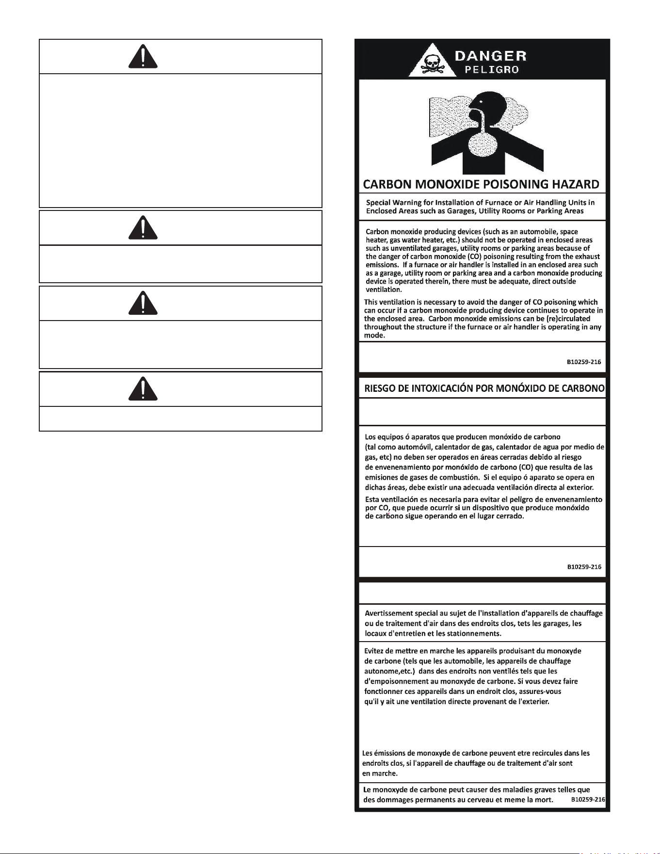
CO can cause serious illness including permanent brain
damage or death.
Advertencia especial para la instalación de calentadores ó
manejadoras
de aire en áreas cerradas como estacionamientos ó cuartos de servicio.
El monóxido de carbono puede causar enfermedades severas
como daño cerebral permanente ó muerte.
Las emisiones de monóxido de carbono pueden circular a través
del aparato cuando se opera en cualquier modo.
RISQUE D'EMPOISONNEMENT AU
MONOXYDE DE CARBONE
Cette ventilation est nécessaire pour éviter le danger d'intoxication
au CO pouvant survenir si un appareil produisant du monoxyde
de carbone continue de fonctionner au sein de la zone confinée.
WARNING
To avoid property damage, personal injury or death due to
electrical shock, this unit MUST have an uninterrupted,
unbroken electrical ground. The electrical ground
circuit may consist of an appropriately sized electrical
wire connecting the ground lug in the unit control box to
the building electrical service panel. Other methods of
grounding are permitted if performed in accordance with the
National Electric Code (NEC)/ American National Standards
Institute (ANSI)/ National Fire Protection Association (NFPA)
70 and local/state codes. In Canada, electrical grounding is
to be in accordance with the Canadian Electric Code (CSA)
C22.1.
WARNING
This product is factory-shipped for use with 24VAC/1
phase/60Hz electrical power supply. DO NOT configure this
cased coil to operate with any other power supply.
WARNING
When installing or servicing this equipment, safety clothing,
including hand and eye protection, is strongly recommended.
If Installing in an area that has special requirements (hard
hats, etc.), Observe these requirements.
WARNING
Failure to properly reconnect sensor wires may result in
Error Codes and the unit not operating.
4
2 SHIPPING INSPECTION
Upon receiving the product, inspect the unit for shipping
damage. Shipping damage and subsequent investigation
is the responsibility of the carrier. Verify the model number,
specications, electrical characteristics and accessories are
correct prior to installation. The distributor or manufacturer
will not accept claims from dealers for transportation damage
or installation of incorrectly shipped units.
2.1 Parts
Also inspect the unit to verify all required components
are present and intact. Report any missing components
immediately to the distributor. Use only factory authorized
replacement parts (see Section 4). Make sure to include the
full product model number and serial number when reporting
and/or obtaining service parts.
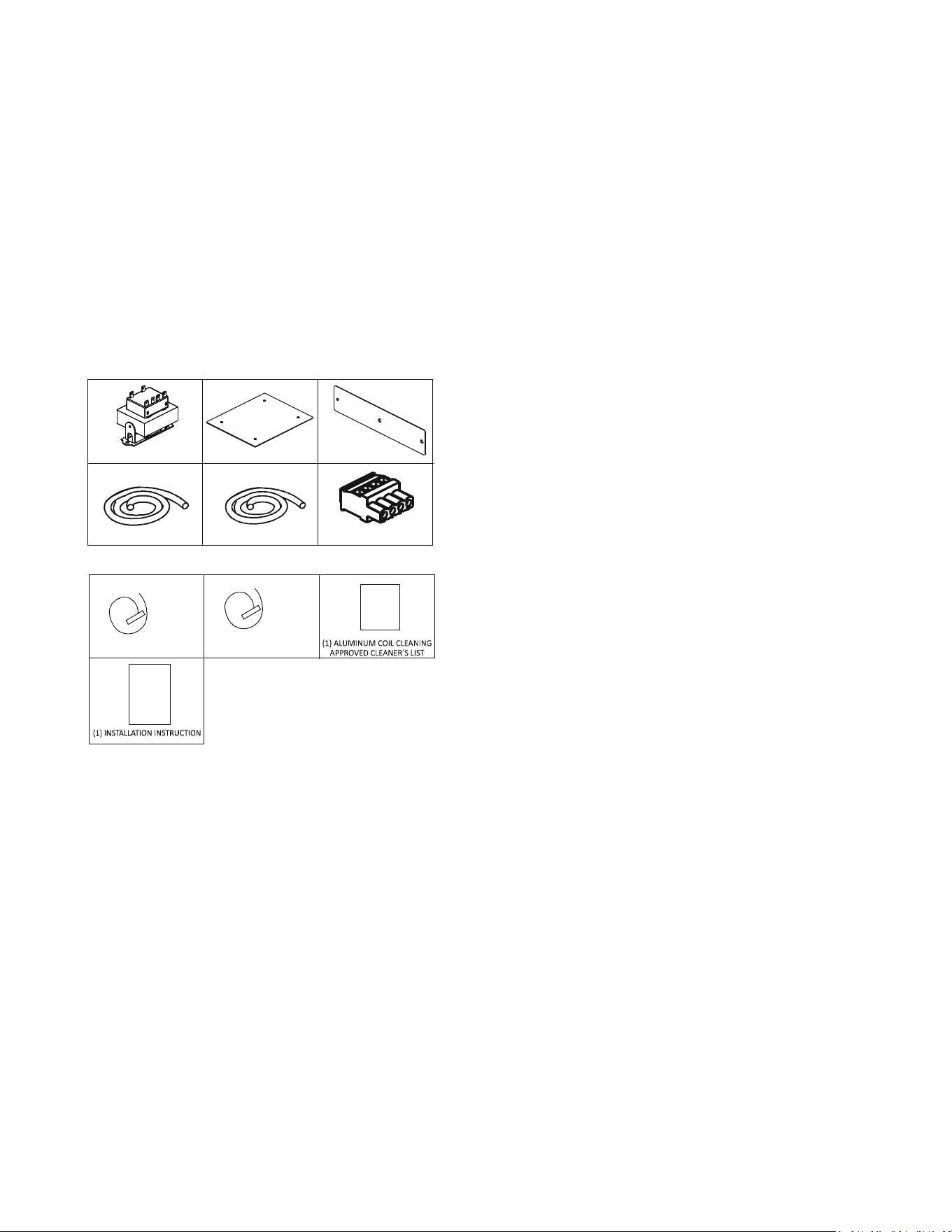
Transformer Installation Components
(1) TRANSFORMER
(1) BRACKET A
(1) BRACKET B
(1) WIRE (Red)
(1) WIRE (Black)
(1)TERMINAL CONNECTOR
(1) WIRE HARNESS
(1) WIRE HARNESS
TP-109(*)
IO-453(*)
Yellow
Purple
Green
Black
Gray
Red
Blue
Transformer Kit Components
Literature Bag Components
2.2 Handling
Use caution when handling the unit. Do not carry unit with
hooks or sharp objects. The preferred method of carrying
the unit after arrival at the job site is by two-wheel hand truck
from the back or sides or by hand carrying at the cabinet
corners. Take proper precautions when carrying/handling
unit to avoid any damage to the piping.
3 CODES & REGULATIONS
This product is designed and manufactured to comply with
applicable national codes. The Product shall be installed
in accordance with national wiring regulations. Installation
in accordance with such codes and/or prevailing local
codes/regulations is the responsibility of the installer.
Compliance with natural gas regulations shall be observed.
The manufacturer assumes no responsibility for equipment
installed in violation of any codes or regulations.
The United States Environmental Protection Agency
(EPA) has issued various regulations regarding the
introduction and disposal of refrigerants. Failure to
follow these regulations may harm the environment and
can lead to the imposition of substantial nes. Should you
have any questions please contact the local oce of the EPA
and/or refer to the EPA’s website www.epa.gov.
4 REPLACEMENT PARTS
When reporting shortages or damages, or ordering repair
parts, give the complete product model and serial numbers
as stamped on the product.
Replacement parts for this product are available through
your contractor or local distributor. Your nearest distributor
can be located online at www.daikincomfort.com or by
contacting:
HOMEOWNER SUPPORT
DAIKIN COMFORT TECHNOLOGIES
MANUFACTURING, L.P.
19001 KERMIER ROAD,
WALLER, TX 77484
855-770-5678
The appliance shall be installed in accordance with national
wiring regulations This product was tested at an external
static pressure up to 0.6 WC. None of the components in
this product line are designed or approved to be suitable
for outdoor use.
5 PRE-INSTALLATION CONSIDERATIONS
The R-32 Sensor must be installed and powered for
service. Ensure that the grommet is installed through the
access panel knockout hole. Sensor bracket assemblies
are shipped with two zip ties, one of which is designed for
strain relief. This zip tie must be kept attached to bracket
and wiring. Follow routing diagram as shown in gure 25 or
26 depending on orientation of install. This wiring is intended
to be passed through the access hole of the furnace. If a
hole must be cut into the furnace, ensure that the wiring is
well protected from mechanical damage and that the hole is
free from burrs or sharp edges. Utilize a protective coating
for all exposed metallic edges.
This appliance is equipped with a leak detection device
which must be wired through the A2L Connector on the
furnace PCB or Non-A2L Furnace Integration Kit.
Scenario 1: A2L Certied Function on Daikin Family
Furnace PCB.
The control board mitigation mode is set to ‘ON’ by default.
The leak detection device must be installed to the port
labeled for A2L input. If this port is not available on the
board, then you must follow instructions in Scenario 2.
5
Verify that the A2L function (this is required for R-32
integration) is enabled on the furnace board PCB. Refer to
the furnace IO for further instruction on how to toggle this
function from disabled to enabled. The A2L verication step
as described on the furnace IO must be completed before
the unit is commissioned. If the test is not successful, call
1-855-DAIKIN1, option 3, for further assistance.
Scenario 2: NO A2L function on furnace PCB.
The leak detection device must be wired directly to the
Non-A2L furnace integration kit board of an approved
communicating Furnace. Utilize the AUX port on the
parent PCB to wire in the Non-A2L Furnace Integration Kit
and follow instructions in the related IO-7021 installation
manual for mounting.
If additional charge is required, you must contact Daikin
Comfort’s Homeowner Support Line.
5.1 Preparation
Keep this document with the unit. Carefully read all
instructions for the installation prior to installing product.
Make sure each step or procedure is understood and any
special considerations are taken into account before starting
installation. Assemble all tools, hardware and supplies
needed to complete the installation. Some items may need
to be purchased locally. Make sure everything needed to
install the product is on hand before starting.
The Indoor equipment mitigation requirements are calculated
at sea level. For higher altitudes adjust the minimum room
area specied on the Serial Plate by the corresponding
altitude adjustment factor shown below. Table 1 is provided
as a reference.
Adjusted room area (A
min
adj
) is the product of the minimum
room area specied in the serial plate and the adjustment
factor AF, as shown in the below formula
A
min adj
= A
min
(serial plate) * AF
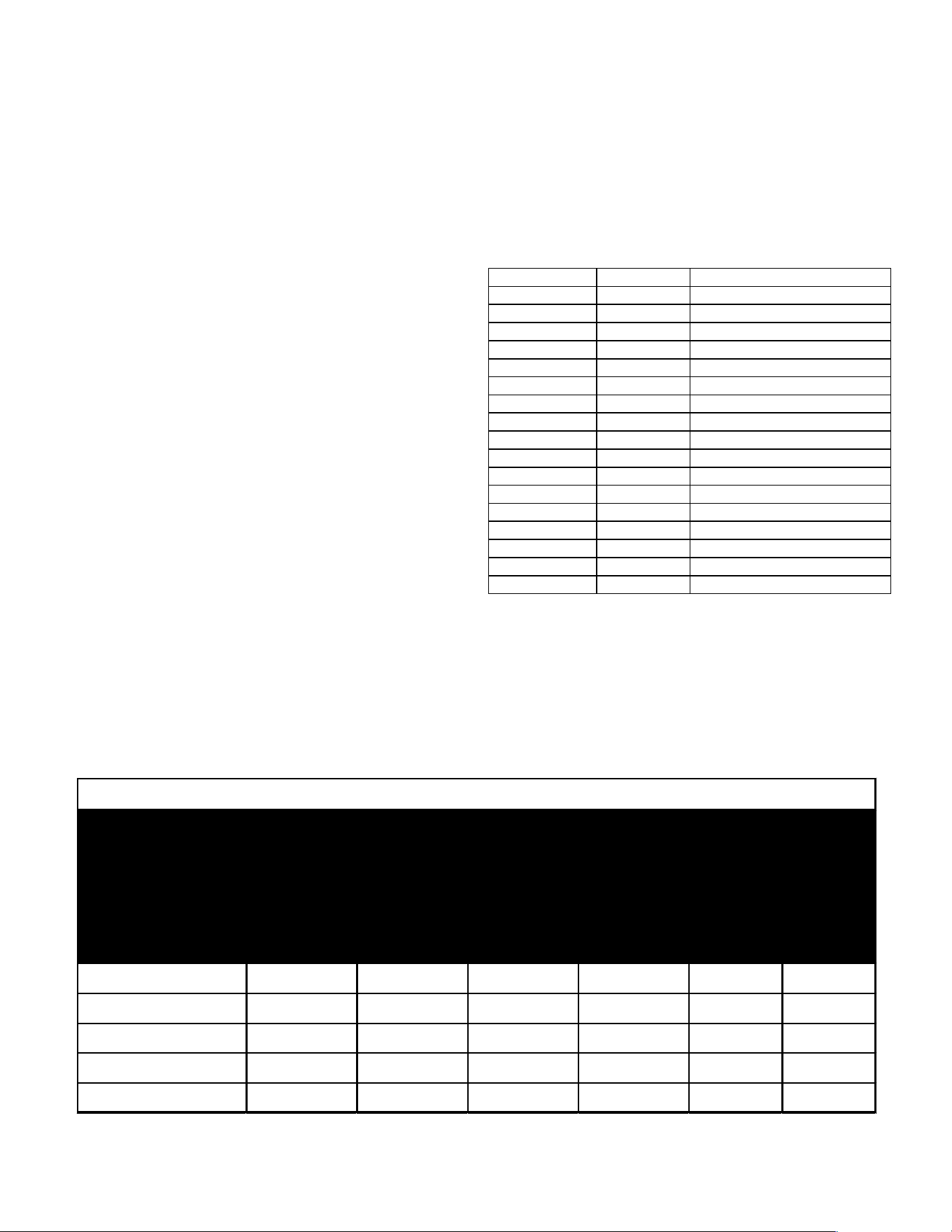
Height in meters Height in feet Altitude Adjustment Factor (AF)
At sea level At sea level 1.00
1-200 1-660 1.02
200-400 660-1320 1.03
400-600 1320-1970 1.05
600-800 1970-2630 1.07
800-1000 2630-3290 1.09
1000-1200 3290-3940 1.11
1200-1400 3940-4600 1.13
1400-1600 4600-5250 1.15
1600-1800 5250-5910 1.17
1800-2000 5910-6570 1.19
2000-2200 6570-7220 1.21
2200-2400 7220-7880 1.24
2400-2600 7880-8540 1.26
2600-2800 8540-9190 1.29
2800-3000 9190-9850 1.31
3000-3200 9850-10500 1.34
Table 1
Vertical Cased Coil Mitigation Chart
Table 2
It is the installer’s responsibility to verify that actuation of mitigation procedures are operational with minimum required
airow according to the chart.
Model
Maximum
Total System
Refrigerant
Charge
(oz)
Maximum
Total System
Refrigerant
Charge
(kg)
Minimum Air
Conditioned
Room Area
(m
2
)
Minimum Air
Conditioned
Room Area
(ft
2
)
Minimum
Mitigation
Airflow
(m
3
/hr)
Minimum
Mitigation
Airflow
(CFM)
2.0T Match-up 132 3.74 11.12 120 366.89 216
2.5T Match-up 131 3.73 11.08 119 365.49 215
3.0T Match-up 138 3.93 11.66 126 384.93 227
4.0T Match-up 155 4.39 13.05 140 430.73 254
5.0T Match-up 185 5.26 15.62 168 515.55 303
Cased Coil Mitigation Chart
6
5.2 System Matches
The entire system (combination of indoor and outdoor sections)
must be manufacturer approved and Air-Conditioning,
Heating, and Refrigeration Institute (AHRI) listed.
NOTE: Installation of unmatched systems is not permitted.
Damage or repairs due to installation of unmatched systems
is not covered under the warranty.
5.3 Clearances
The unit horizontal clearance from a surface may be 0” from
walls and 1” from other units. However, service clearance
must take precedence. A minimum of 24” in front of the
unit for service clearance is required. Additional clearance
on one side or top will be required for electrical wiring
connections. Consult all appropriate regulatory codes prior
to determining nal clearances. In installations that may lead
to physical damage (i.e. a garage) it is advised to install a
protective barrier to prevent such damage. Always install
units such that a positive slope in condensate line (¼” per
foot) is allowed.
Further, any joints made in the installation between parts of
the refrigerating system must be accessible for maintenance.
NOTE: Furnace application requires that the installer MUST
review and strictly follow ALL furnace installation clearance
guidelines. Failure to do so may result in property/equipment
damage, personal injury or death.
CONSULT ALL APPROPRIATE REGULATORY CODES
WHEN DETERMINING FINAL CLEARANCES
5.4 Access
This unit should be installed in a manner so that it is not
accessible to the public.
WARNING: FLAMMABLE MATERIALS
WHEN INSTALLED IN A ROOM WITH AN AREA LESS THAN
THAT OUTLINED IN TABLE 2, THAT ROOM SHALL BE WITHOUT
CONTINUOUSLY OPERATING OPEN FLAMES (FOR EXAMPLE
AN OPERATING GAS APPLIANCE) OR OTHER POTENTIAL
IGNITION SOURCES (FOR EXAMPLE AN OPERATING ELECTRIC
HEATER, HOT SURFACE).
6 APPLICATION INFORMATION
Coils are designed for indoor installation only and must be
installed downstream (discharge air) of the furnace and
upstream (return air) of the modular blower. This product
may be installed in upow or downow orientations.
If the unit is in an unconditioned area with high ambient
temperature and/or high humidity, the coil may be subject
to nuisance sweating of the casing. On these installations,
a wrap of 2” berglass insulations with a vapor barrier is
recommended. Do not cover warning labels and serial plate.
WARNING
AUXILIARY DEVICES WHICH MAY BE A POTENTIAL IGNITION
SOURCE ARE NOT TO BE INSTALLED IN THE DUCT WORK.
SUCH POTENTIAL IGNITION SOURCES INCLUDE HOT
SURFACES WITH A TEMPERATURE EXCEEDING 650°C AND
ELECTRIC SWITCHING DEVICES. FOR EXAMPLE, ELECTRONIC
AIR FILTERS ARE A POTENTIAL IGNITION SOURCE.
WARNING
ONLY AUXILIARY DEVICES APPROVED BY THE APPLIANCE
MANUFACTURER OR DECLARED SUITABLE WITH THE
REFRIGERANT SHALL BE INSTALLED IN CONNECTING
DUCTWORK. IF AN EXISTING DEVICE IS NOT APPROVED
BY THE APPLIANCE MANUFACTURER FOR USE WITH
THE REFRIGERANT, THE DEVICE MUST BE REMOVED OR
DISCONNECTED.
CAUTION
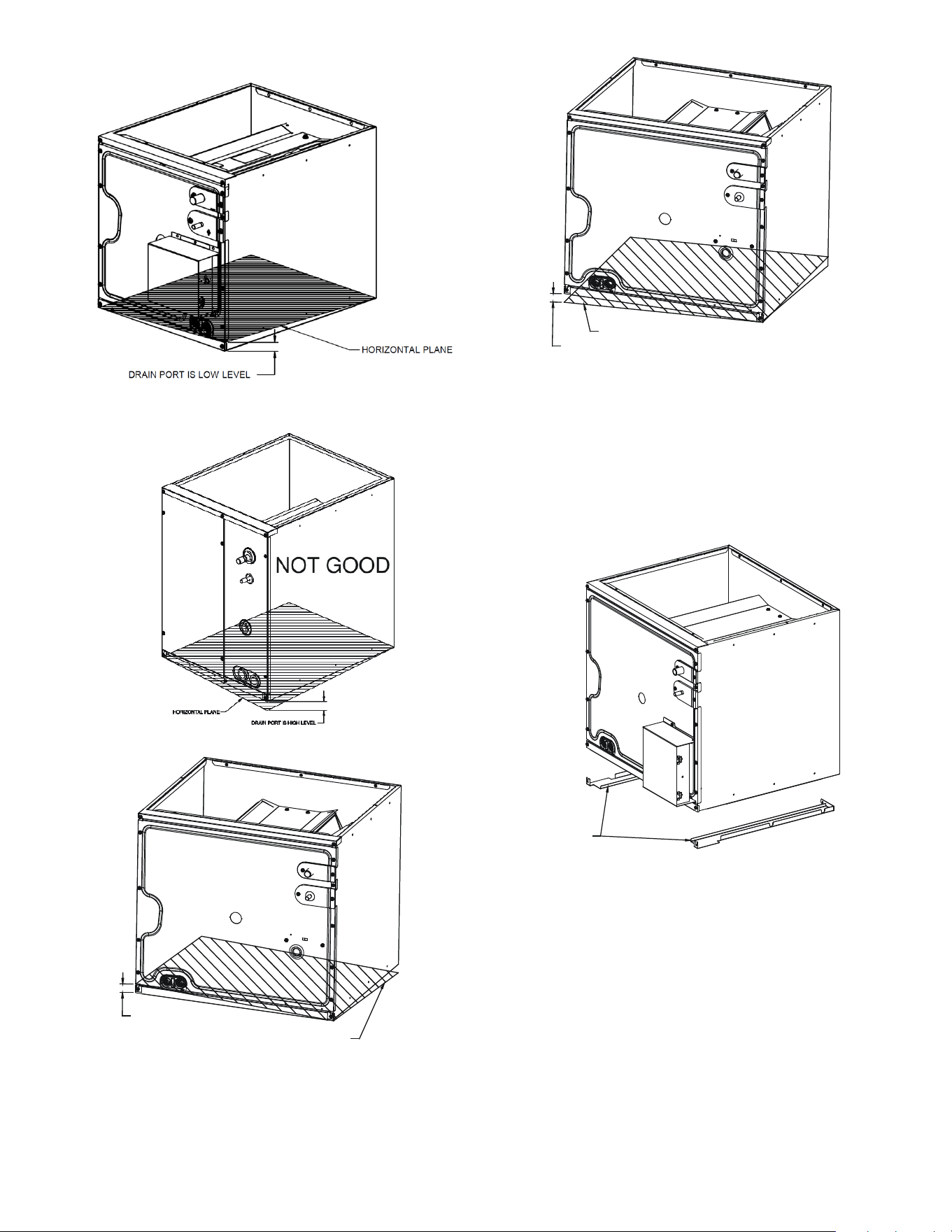
Check horizontality level of the unit with spirit level. Don’t
tilt the unit down that makes it difficult to drain even though
the level is within criteria of spirit level. See figure 1. Such
tilted units may cause water leaks.
A coil installed with a furnace may be the same width as
the furnace or may be one size larger than the furnace but
cannot be smaller than the furnace. EXAMPLE: A “C” width
coil may be installed with a “B” or a “C” width furnace.
7
GOOD
G
O
O
D
H
O
R
I
Z
O
N
T
A
L
P
L
A
N
E
D
R
A
I
N
P
O
R
T
I
S
L
O
W
L
E
V
E
L
N
O
T
G
O
O
D
D
R
A
I
N
P
O
R
T
I
S
H
I
G
H
L
E
V
E
L
H
O
R
I
Z
O
N
T
A
L
P
L
A
N
E
Figure 1
NOTE: The coil must be installed with the line set and drain
openings to the front of the furnace or modular blower.
6.1 Filler Plates
Filler plates are supplied on all 17.5, 21.0 & 24.5 inch chassis
to be used or adapting the unit to a furnace one size smaller.
If the plenum and furnace openings are the same size, the
ller plates must be removed. See Figure 2.
FILLER PLATE
Figure 2
6.2 Insulation Kit
IMPORTANT NOTE: To prevent coil pan “sweating”, a coil
insulation kit (DPICX) must be applied to minimize pan
sweating in applications where operating conditions exceed
80% RH. Insulation kits are available through your local
distributor. The DPICX is not supplied with the cased coil.
See Table 3 for the correct DPICX and follow the instructions
provided with the kit for installation.
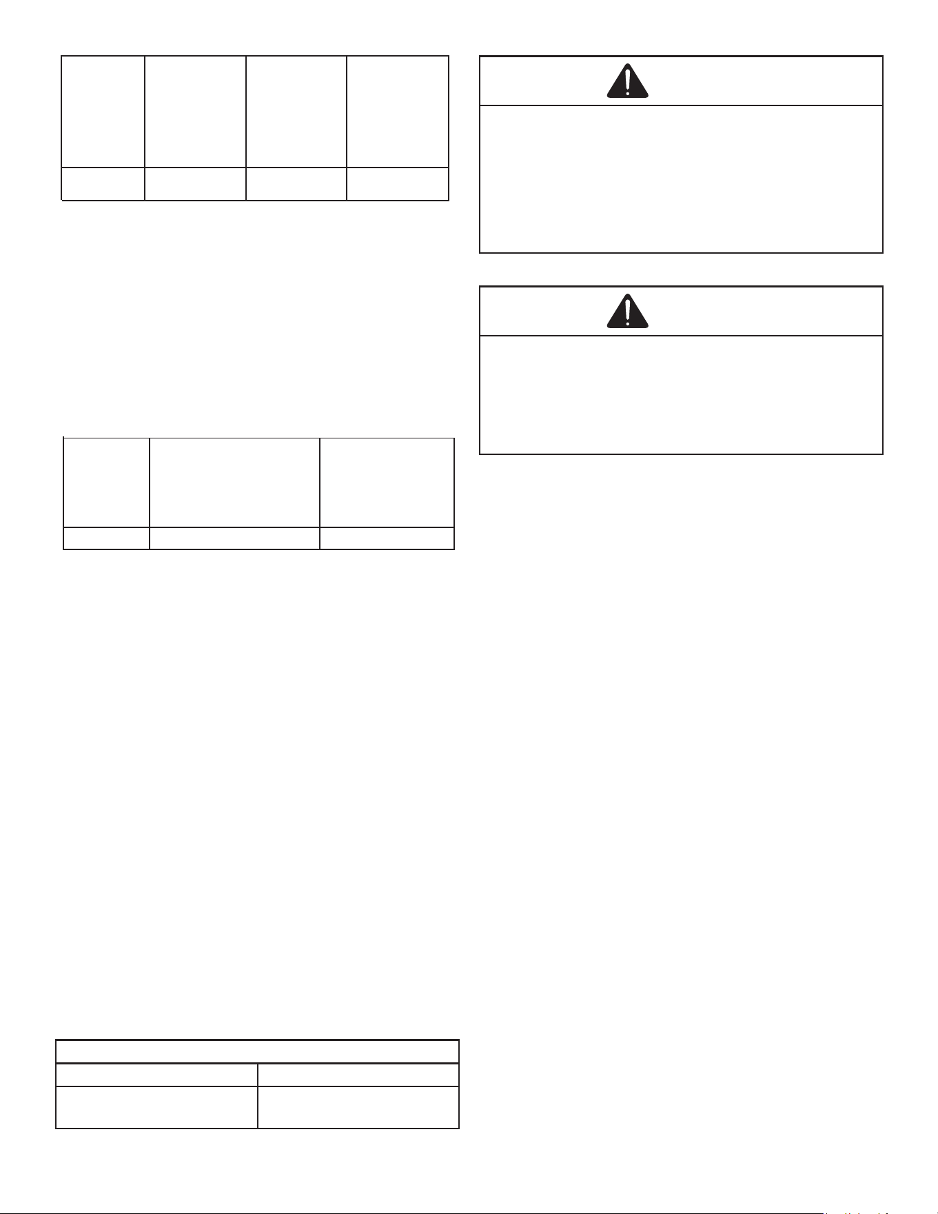
8
Cased Coil
CAPEA2418B
CAPEA3022B
CAPEA3626B
CAPEA2418C
CAPEA3022C
CAPEA3626C
CAPEA4830C
CAPEA4830D
CAPEA6030D
CAPEA6030C
Kit Model DPICX-BB DPICX-CB DPICX-DB
INSULATION KIT
Table 3
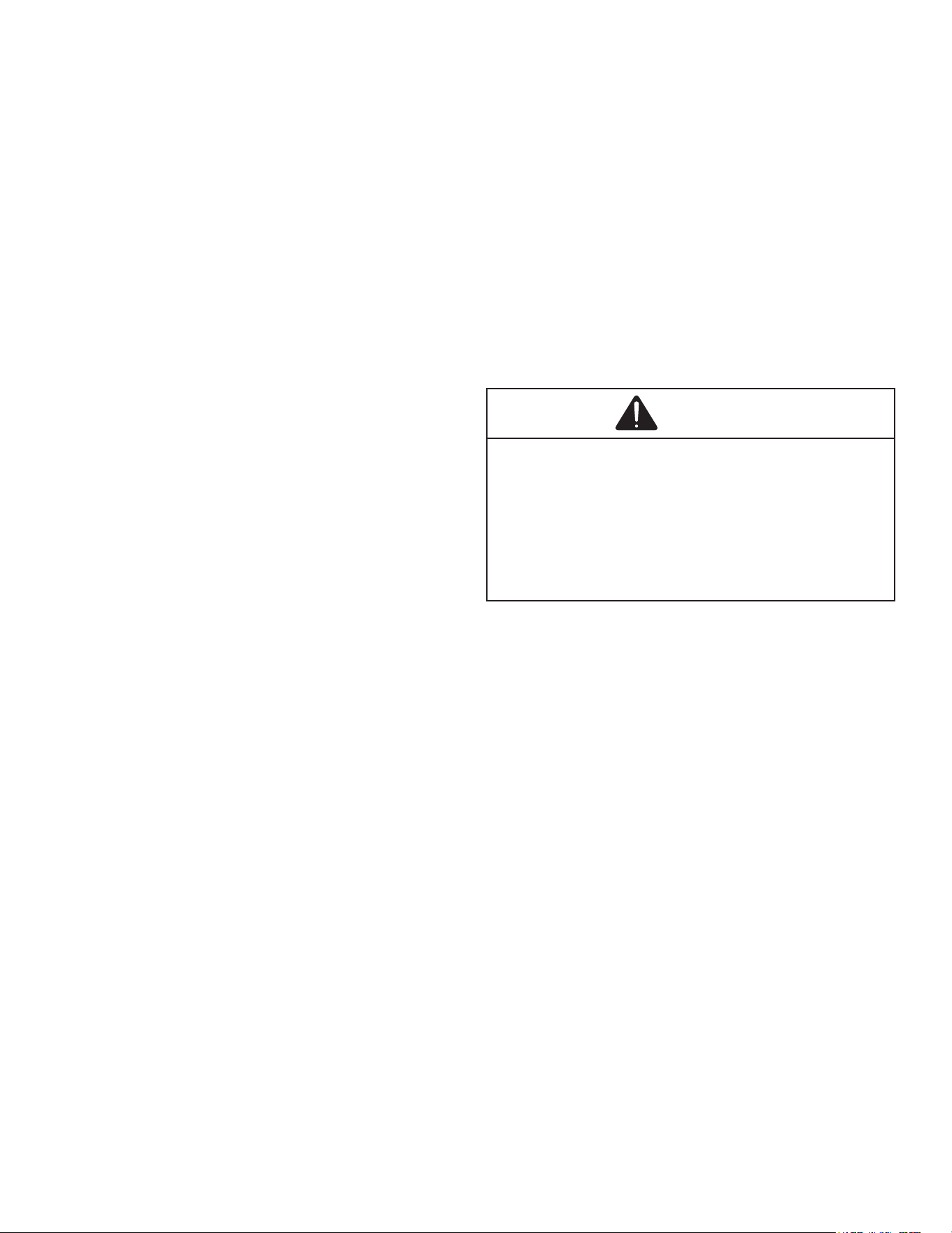
6.3 Down Flow Kit (For CAPEA4830C, D &
CAPEA6030C, D)
IMPORTANT NOTE: To prevent coil “water leak”, a coil down
ow kit (DFKE) must be installed when the coil is installed
with down ow orientation regardless of the humidity. Down
ow kits are available through your local distributor. The
DFKE is not supplied with the cased coil.
See Table 4 for the correct DFKE and follow the instructions
provided with the kit for installation.
Cased Coil
CAPEA2418B, C
CAPEA3022B, C
CAPEA3626B, C, and D
CAPEA4830C, D
CAPEA6030C, D
Kit Model DFKE-02
Not Necessary
DOWN FLOW KIT
Table 4
7 RETURN DUCTWORK
Do not locate the return ductwork in an area that can introduce
toxic or objectionable fumes/odors into the ductwork.
UV Lamp is only available for CAPEA: Clean Comfort brand
UV coil puriers also can be purchased from distributor.
Maximum UV lamp diameter to be used per delta plate
knockout design is 1.375” to reduce the possibility of air
leak. Installer should apply the UV-C warning label on the
maintenance panel when UV-C lamp is installed.
The power source must be installed external of the unit.
Ensure that the wiring is routed through the Access Panel
knockout with the grommet included. A magnetic door
switch must be installed to avoid any accidental ultraviolet
exposure during service. The power supply must be installed
in parallel with the approve A2L control board utilizing the
24V AUX port to ensure that power to the UV is turned o
during mitigation mode.
• Ultraviolet radiation hazard symbol IEC 60417-6040.
• Operator’s manual symbol ISO 7000-0790.
Refer to UV coil puriers product specication and installation
manual for additional details.
UV-C Part Numbers
Models Lamp
UC18S15-24
UC18S15-24B
UCP-16013
UCP-16012
WARNING
- UNINTENDED USE OF APPLIANCES OR DAMAGE TO THE
HOUSING MAY RESULT IN THE ESCAPE OF DANGEROUS
UV-C RADIATION.
- APPLIANCES THAT ARE OBVIOUSLY DAMAGED MUST NOT
BE OPERATED.
- UV-C BARRIERS BEARING THE ULTRAVIOLET RADIATION
HAZARD SYMBOLS SHOULD NOT BE REMOVED.
- DO NOT OPERATE UV-C LAMPS OUTSIDE OF THE
APPLIANCE.
8 REFRIGERANT PIPING WORK
WARNING
ONLY BRAZING TECHNIQUES OR APPROVED MECHANICAL
JOINTS SHOULD BE USED TO CONNECT REFRIGERANT
TUBING CONNECTIONS. NON-APPROVED MECHANICAL
CONNECTORS AND OTHER METHODS ARE NOT PERMITTED
IN THIS SYSTEM CONTAINING R-32 REFRIGERANT.
APPROVED MECHANICAL JOINTS WILL BE DETAILED IN THE
PRODUCT’S SPECIFICATION SHEETS.
NOTE: Refrigerant tubing must be routed to allow adequate
access for servicing and maintenance of the unit.
Do not handle coil assembly with manifold or owrator tubes.
Doing so may result in damage to the tubing joints. Always
use clean gloves for handling coil assemblies.
Installation of pipe-work must be kept to a minimum. Pipe-
work including piping material, pipe routing and installation
must be protected from physical damage and shall not
be installed in an unventilated space. Equipment piping
in an occupied space shall be installed in such a way to
protect against accidental damage in operation and service.
Precautions must be taken to avoid excess vibration or
pulsation to refrigeration piping. Protection devices, piping
and ttings shall be protected as far as possible against
adverse environmental eects, for example, the danger
of water collecting and freezing in relief pipes or the
accumulation of dirt and debris. Steel pipes and components
shall be protected against corrosion with a rustproof coating
before applying any insulation, Any solenoid valves and
piping in the refrigerant systems must be so designed
and installed to minimize the likelihood of hydraulic shock
damaging the system. Solenoid valves must be must not
block in liquid refrigerant unless adequate relief is provided
to the refrigerant system’s low pressure side. Provisions
must be made for expansion and contraction of long runs
of piping.
Follow standards related to ASHRAE 15, ASHRAE 15.2,
IAPMO Uniform Mechanical Code, ICC International
Mechanical Code or CSA B52 during any installation.
Piping must be accessible for inspection prior to being
covered or enclosed in compliance with national and local
codes.
9
Flexible pipe elements must be protected against
mechanical damage, excessive stress by torsion, or
other forces. They should be checked for mechanical
damage annually. The indoor equipment and pipes must
be securely mounted and guarded such that accidental
rupture of equipment cannot occur from such events as
moving furniture or reconstruction activities. Field brazed
joints indoors shall be tightness tested.
LEAK DETECTION AND EVACUATION METHODS
Extreme care shall be taken not to overll the refrigerating
system. Prior to recharging the system, it shall be pressure
tested with the appropriate purging gas. No refrigerant
shall be used for pressure testing to detect leaks. The
system shall be leak tested on completion of charging prior
to commissioning. A follow-up leak test shall be conducted
prior to leaving the site.
Using dry nitrogen or dry helium, pressurize the system as
mentioned below.
System Pressure Testing
Once all of the refrigerant line connections are completed,
Perform a 3-step nitrogen pressure test as mentioned below.
No refrigerant shall be used for pressure testing. Extreme
care shall be taken not to over pressurize the system
described in step 3.
1. Pressurize the system with nitrogen to 150 PSIG and
hold for 3 minutes. If any pressure drops occur, locate,
and repair leaks and repeat step 1.
2. Pressurize the system with nitrogen to 325 PSIG and
hold for 5 minutes. If any pressure drops occur, locate,
and repair leaks and repeat step 1.
3. Pressurize the system with nitrogen to Maximum
Allowable Pressure as listed in the serial plate and hold
for 1 hour (4 hours recommended). If any pressure
drops occur, locate, and repair leaks and repeat step 1.
If leaks are found, repair them. After repair, repeat the leak
pressure test described above.
If no leaks exist, proceed to system evacuation and charging.
The minimum test pressure for the low side of the system
shall be the low side Maximum Allowable Pressure and the
minimum test pressure for the high side of the system shall
be the high side Maximum Allowable Pressure, unless the
high side of the system cannot be isolated from the low
side of the system in which case the entire system shall
be pressure tested to the low side Maximum Allowable
Pressure.
For system evacuation follow the below procedure:
1. Connect the vacuum pump with 250 micron capability to
the service valves.
2. Evacuate the system to 500 microns or less using
suction and liquid service valves. Using both valves is
necessary.
3. Close pump valve and hold vacuum for 10 minutes.
Typically pressure will rise during this period.
• If the pressure rises to 500 microns or less and
remains steady the system is considered leak-free;
proceed to start-up.
• If pressure rises above 500 microns moisture and /or
noncondensables may be present or the system may
have a small leak. Return to step 2: If the same result
is encountered check for leaks as previously indicated
and repair as necessary then repeat evacuation.
CAUTION
Follow the points below:
• Use a tube cutter and flaring block suitable for the
type of refrigerant.
• To prevent dust, moisture or other foreign matter from
infiltrating the piping, either pinch the end or cover it
with tape.
• Do not allow anything other than the designated
refrigerant to get mixed into the refrigerant circuit.
If an refrigerant gas leaks while working on the unit,
immediately ventilate the room.
Field brazed joints indoors shall be tightness tested. The
test method shall have a sensitivity of 5 grams per year
of refrigerant or better under a pressure of at least 0.25
times the maximum allowable pressure. No leak shall be
detected (Should be leak tight).
8.1 Tubing Size/Length
Give special consideration to minimize the length of
refrigerant tubing when installing cased coil. Refer to outdoor
unit INSTALLATION & SERVICE REFERENCE for line set
conguration guideline. If possible, allow adequate length
or tubing such that the coil may be removed (for inspection
or cleaning services) from the cabinet without disconnecting
the tubing.
8.2 Cut O The Spin Closure
• This coil is shipped containing gas under 150 P.S.I.G.
Release pressure from the gas piping pressure-
release device before initiating piping work.
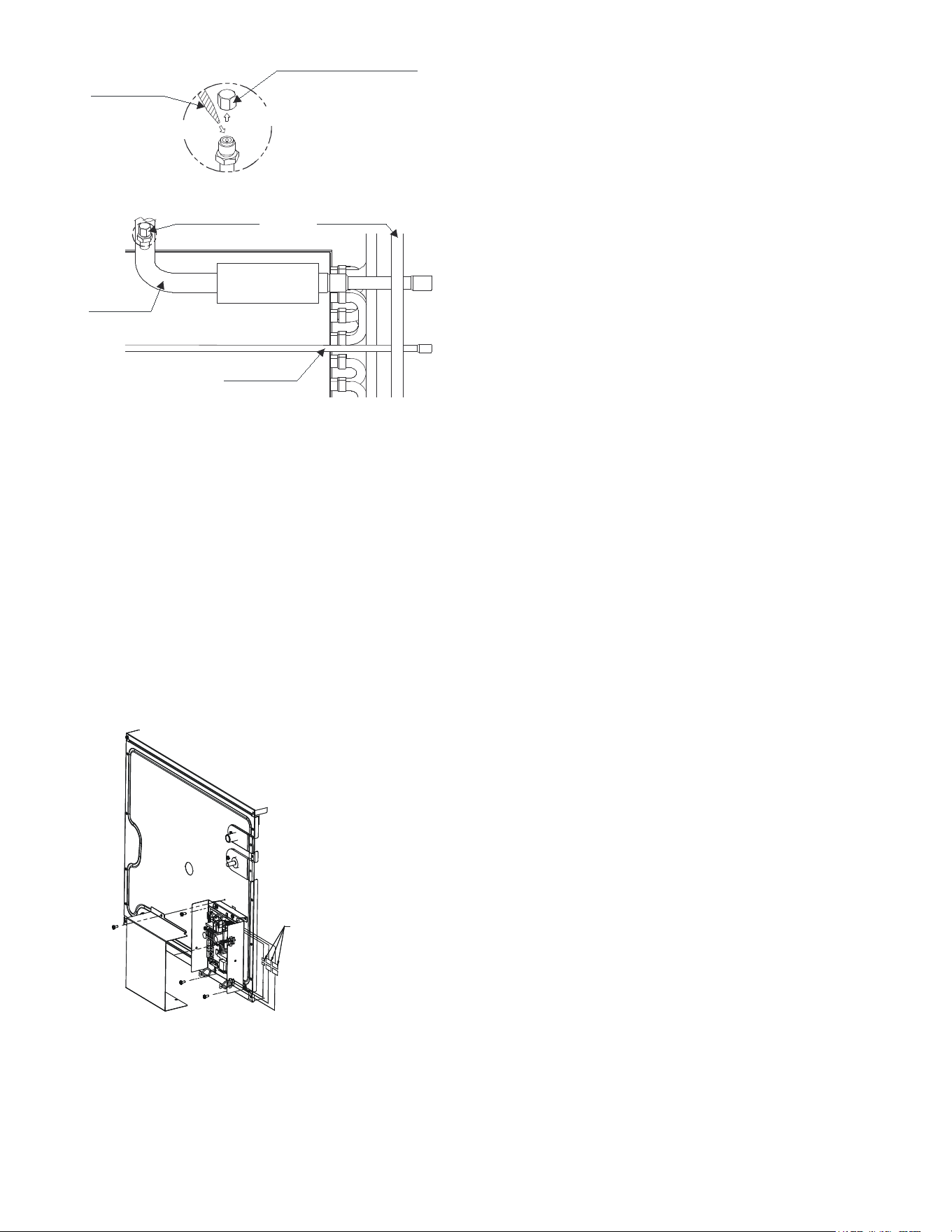
10
Detail
Cap
After the work is finished,
Reinstall cap.
Sharp object
Gas piping
Front panel
Liquid piping
Pressure
release device
(2) Push
(1) Remove
Figure 3
• Using a tube cutter, cut o the factory spun end of
both the liquid and gas line piping.
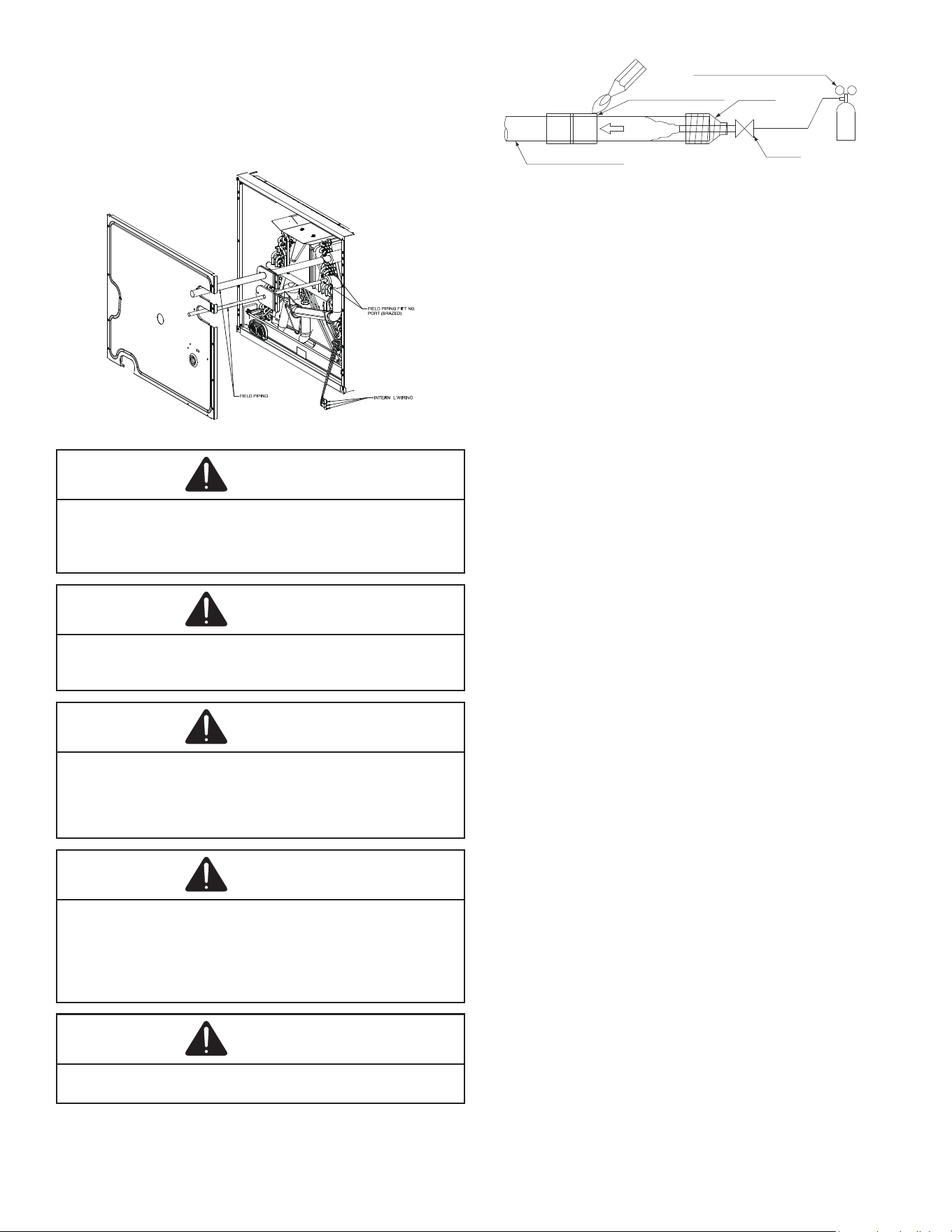
8.3 Disconnect Internal Control Wiring
• Disconnect the control panel wiring from component
wiring using the EEV, Pressure sensor and
Thermistor connectors located on the outside of the
control panel. See Figure 4.
NOTE: To prevent component wiring damage, the control
panel should be removed from the front panel. Removing
the control panel will assist in allowing the wiring to be safely
pushed through the panel wireway. The control panel is
detached from the front panel by removing the four mounting
screws located on the four corners of the control panel.
I
N
T
E
R
N
A
L
W
I
R
I
N
G
C
O
N
N
E
C
T
O
R
S
(
E
E
V
,
P
R
E
S
S
U
R
E
S
E
N
S
O
R
A
N
D
T
H
E
R
M
I
S
T
E
R
)
I
N
T
E
R
N
A
L
W
I
R
I
N
G
C
O
N
N
E
C
T
O
R
S
(
E
E
V
,
P
R
E
S
S
U
R
E
S
E
N
S
O
R
A
N
D
T
H
E
R
M
I
S
T
E
R
)
Figure 4
8.4 Connect Piping
This system must be charged with R32 Refrigerant in order
to operate safely.
When breaking into the refrigerant circuit to make repairs
- or for any other purpose - conventional procedures shall
be used, However, for ammable refrigerants it is important
that best practice be followed, since ammability is a
consideration. The following procedures shall be adhered
to:
- safely remove refrigerant following local and national
regulations;
- evacuate;
- purge the circuit with inert gas (optional for A2L);
- evacuate (optional for A2L);
- continuously ush or purge with inert gas when using
ame to open circuit; and
- open the circuit.
The refrigerant charge shall be recovered into the correct
recovery cylinders if venting is not allowed by local and
national codes.
For appliances containing ammable refrigerants, the
system shall be purged with oxygen-free nitrogen to render
the appliance safe for ammable refrigerants. This process
might need to be repeated several times. Compressed air
or oxygen shall not be used for purging refrigerant systems.
For appliance containing ammable refrigerants, refrigerant
purging shall be achieved by breaking the vacuum in the
system with oxygen-free nitrogen and containing to ll
until the working pressure is achieved, then venting to
atmosphere, and nally pulling down to a vacuum. This
process shall be repeated until no refrigerant is within the
system. When nal oxygen-free nitrogen charge is used,
the system shall be vented down to atmospheric pressure
to enable work to take place.
Ensure that the outlet for the vacuum pump is not close
to any potential ignition sources and that ventilation is
available. Ensure that when brazing, any labels or wiring is
suciently protected from damage.
For Single Front Panel
• Remove the front panel while cautiously guiding
component wiring back through panel wireway.
• Unscrew two grommets both for gas and liquid
tubing.
• Slide those grommets along eld tubing.
• Braze up to the eld piping tting port while cooling
the sensor, EEV, service valve and the thermal
insulation. Braze joints should be made only with
the connectors provided external to the cabinet. Do
not alter the cabinet nor braze inside the cabinet. To
avoid overheating after brazing, quench all brazed
joints with water or a wet rag.
11
NOTE: To prevent damage caused by heat when brazing
the eld piping, cover the pipe insulation, the internal wiring,
and the thermal sensors inside the insulation with a damp
cloth. Otherwise, the sensors, EEV and service valve may
be damaged by heat of brazing, which leads to a failure of
normal operation.
Figure 5
WARNING
A quenching cloth is strongly recommended to prevent
scorching or marring of the equipment finish when brazing
close to the painted services. Use brazing alloy of 5%
minimum silver content.
WARNING
Refrigerant gas may produce toxic gas if it comes in contact
with fire (as from a heater, stove or cooking device).
Exposure to this gas could cause severe injury or death.
CAUTION
Applying too much heat to any tube can melt the tube.
Torch heat required to braze tubes of various sizes must be
proportional to the size of the tube. Service personnel must
use the appropriate heat level for the size of the tube being
brazed.
CAUTION
When brazing the refrigerant piping, perform nitrogen
replacement first or perform the brazing while feeding
nitrogen into the refrigerant piping. See following figure.
When brazing pipes while feeding nitrogen inside the piping,
make sure to set the nitrogen pressure to 2.9 PSI or less
using a pressure reducing valve.
WARNING
Use of oxygen could result in an explosion resulting in
serious injury or death. Use only dry nitrogen gas.
Refrigerant piping
Part to be brazed Taping
Pressure-reducing valve
Hand
valve
Nitroge
n
Nitrogen
Figure 6
NOTE: Do not use ux when brazing refrigerant piping.
Therefore, use the phosphor copper brazing ller metal
(BCuP) which does not require ux. Flux has an extremely
negative eect on refrigerant piping systems. For instance,
if chlorine based ux is used, it will cause piping corrosion.
Flux containing uorine will damage refrigerant oil.
8.5 Re-assemble the Coil and Controls
• Once heat from the brazed area has dissipated,
route component wiring back through the front panel
wireway.
• Reinstall the tubing grommets and close the front
panels.
• Reinstall the control panel to the front panel using
mounting location holes and factory supplied screws.
• Reconnect Control Panel wiring to component wiring.
• After the work is nished, make sure to check that
there is no gas leak.
• After checking for gas leaks, be sure to insulate the
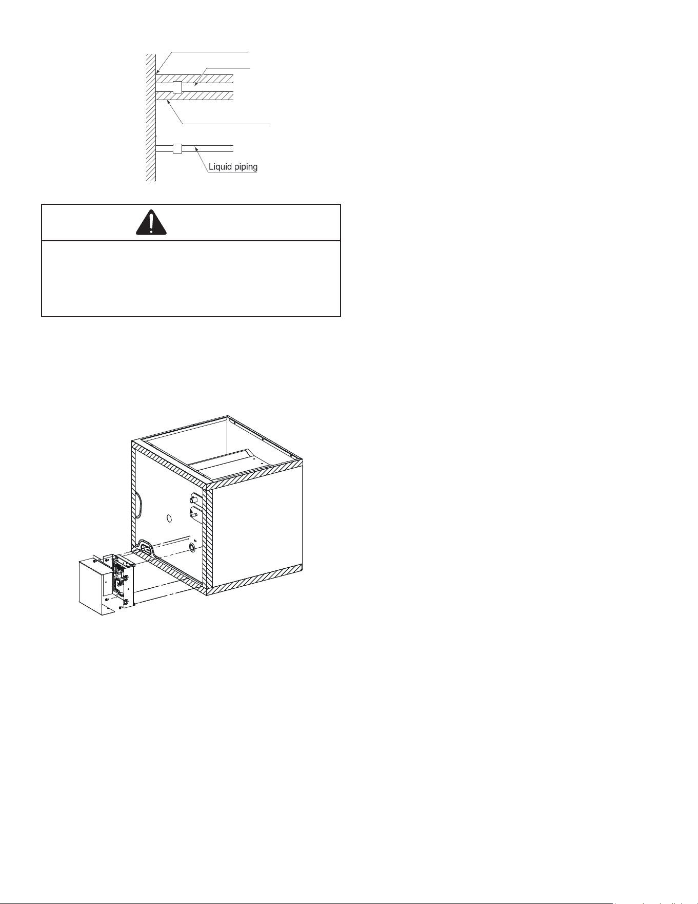
piping connections as shown in Figure 7.
In addition to conventional charge procedures, the following
requirements shall be followed:
1. Ensure that contamination of dierent refrigerants
does not occur when using charging equipment. Hoses
or lines shall be as short as possible to minimize the
amount of refrigerant contained in them.
2. R-32 Refrigerant Cylinders shall be kept in an
appropriate position according to the instructions.
3. Ensure that the refrigeration system is earth grounded
prior to charging the system with refrigerant.
4. Label the system when charging is complete (if not
already).
5. Extreme care shall be taken not to overll the
refrigerating system.
Prior to recharging the system, it shall be pressure-
tested with the appropriate purging gas. The system shall
be leak-tested on completion of charging but prior to
commissioning. A follow up leak test shall be carried out
prior to leaving the site.
Completely insulate gas refrigerant piping in order to
prevent condensation and possible water damage. Failing
to insulate the pipes may cause leaking or burns. Be sure
to use the insulation which can withstand temperatures
of 250°F (120°C) or more. Reinforce the insulation on the
refrigerant piping according to the installation environment.
If environmental conditions may reach 86°F and 80% RH,
condensate may form on the surface of the insulation. To
prevent condensate leakage, reinforce the refrigerant piping
insulation according to the installation environment.
12
Do not leave a gap
Gas piping
Piping heat insulation
material
Cased
Coil
Figure 7
CAUTION
• Do not allow component wiring to become pinched.
Failure to do so may lead to unit failure.
• Be sure to insulate gas piping all the way (required
insulation), to piping connection inside the unit. Any
exposed piping may cause condensation or burns if
touched.
9 SEALING ALONG THE PANEL GAP
IMPORTANT NOTE: To prevent cabinet “sweating”, apply
eld provided insulation tape along all joining surfaces
between the coil, gas furnace, duct work, and panels. See
Figure 8.
Figure 8
10 DRAIN PIPING WORK
In all cooling applications where condensate overow may
cause damage, a secondary drain pan must be provided by
the installer and placed under the entire unit with a separate
drain line properly sloped and terminated in an area visible
to the owner. This secondary drain pan can provide extra
protection to the area under the unit should be the primary
drain plug up and overow. As expressed in our product
warranty, we will not be liable for any damages, structural
or otherwise due to the failure to follow this installation
requirement.
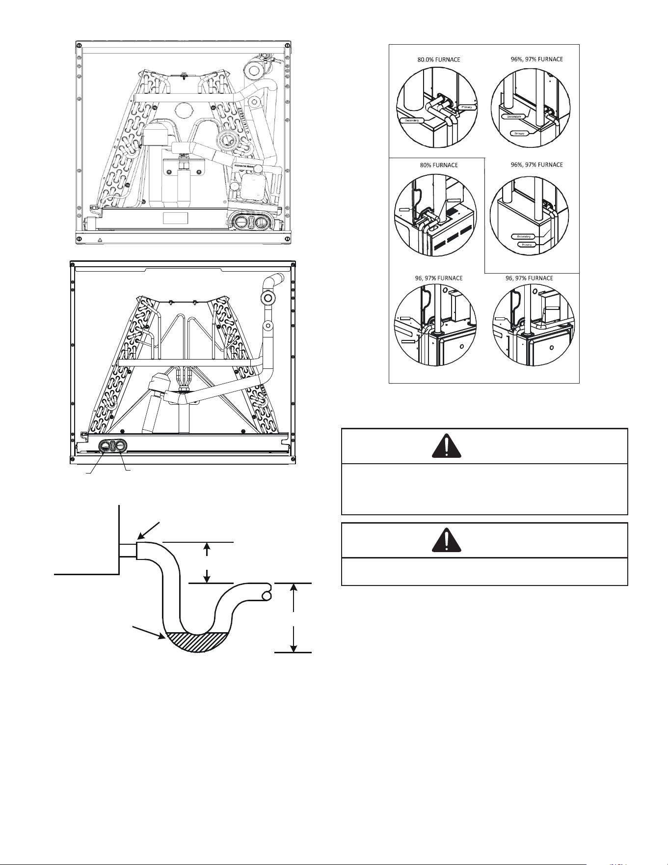
Condensate drain connections are located in the drain pan
at the bottom of the coil/enclosure assembly see Figure
9. Use the female (¾”FPT) threaded tting that protrudes
outside of the enclosure for external connections. The
connectors required are ¾” NPT male, either PVC or metal
pipe and must be hand tightened to a torque of no more than
37 in-lbs, to prevent damage to the drain pan connection. An
insertion depth between .36 to .49 inches (3-5 turns) should
be expected at this torque.
1. Ensure drain pan hole is NOT obstructed.
2. To prevent potential sweating and dripping on to
nished space, it may be necessary to insulate the
condensate drain line located inside the building. Use
Armaex® or similar material.
A secondary condensate drain connection has been
provided for areas where the building codes require it. Use
a downward slope of at least ¼” per foot to provide free
drainage, or as required by local code. Provide required
support to the drain line to prevent bowing. If the secondary
drain line is required, run the line separately from the primary
drain and end it where condensate discharge can be easily
seen.
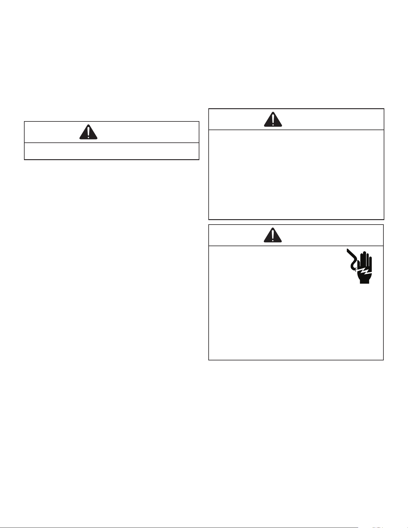
Drain port labeled (A) in Figure 9 is the primary drain and
condensate drain line must be attached to this drain port.
Drain port (B) is for the secondary drain line (if used).
Use Figure 11 as a template for typical drain pipe routing.
This gure shows how to avoid interference with vent piping.
13
A
B
Figure 9
Cased Coil
3" MIN.
POSITIVE LIQUID
SEAL REQUIRED
AT TRAP
Drain
Connection
2" MIN.
Figure 10
CASE FOR B CABINET
CASE FOR C/D CABINET
PRIMARY
SECONDARY
SECONDARY
PRIMARY
PR
IMARY
SECONDAR
Y
Figure 11
CAUTION
• Use steel drain pipe/fittings, or add reflective or high
heat resistive tape, to any pipe or fixtures that is within
1” of the 80% furnace vent pipe. Foil-Mastic Sealant tape
is the preferred method of pipe wrapping material.
CAUTION
If a secondary drain is not installed, the secondary access
must be plugged.
NOTE:
• Water coming from secondary line means the coil
primary drain is plugged and needs immediate
attention.
• Insulate drain lines located inside the building or
above a nished living space to prevent sweating.
The installation must include a “P” style trap that is
located as close as is practical to the evaporator coil.
See Figure 10 for details of a typical condensate line
“P” trap.
NOTE: Units operating in high static pressure
applications may require a deeper eld constructed
“P” style trap than is shown in Figure 10 to allow
proper drainage and prevent condensate overow.
• Trapped lines are required by many local codes. In
the absence of any prevailing local codes, please
refer to the requirements listed in the uniform
mechanical building code.
14
• A drain trap in a draw-through application prevents
air from being drawn back through the drain line
during fan operation, thus preventing condensate
from draining and if connected to a sewer line, to
prevent sewer gases from being drawn into the air
stream during blower operation.
• If using copper drain line, solder a short piece of
pipe, minimum 6” length, to the connector before
installing a drain tting. DO NOT over torque the ¾”
copper connector to the plastic drain connection.
Using a wet rag or heatsink material on the short
piece to protect the plastic drain pan.
CAUTION
If a secondary drain is not installed, the secondary access
must be plugged.
Condensate drain traps with an open vertical Tee between
the cased coil and the condensate drain trap can improve
condensate drainage in some applications, but may cause
excessive air discharge out of the open Tee. We do not
prohibit this type of drain but we also do not recommend it due
to the resulting air leakage. Regardless of the condensate
drain design used, it is the installer’s responsibility to ensure
the condensate drain system is of sucient design to ensure
proper condensate removal from the coil drain pan.
Use of a condensate removal pump is permitted when
necessary. This condensate pump should have provisions
for shutting o the control voltage should a blocked drain
occur. See Auxiliary Alarm Switch section that is in gas
furnace or modular blower manual for more details. A trap
must be installed between the unit and the condensate
pump.
NOTE: This cased coil DOES NOT have auxiliary alarm
switch feature.
IMPORTANT NOTE: The coil is fabricated with oils that may
dissolve Styrofoam
®
and certain types of plastics. Therefore,
the removal pump or oat switch must not contain any of
these materials.
Installation of pipe-work must be kept to a minimum. Pipe
work including piping material, pipe routing and installation
must be protected from physical damage and shall not be
installed in an unventilated space. Equipment piping in any
occupied space shall be installed in such a way to protect
against accidental damage in operation and service.
Precautions must be taken to avoid excessive vibration
or pulsation to refrigeration piping. Protection devices,
piping and ttings shall be protected as fas as possible
against adverse environmental eects, for example, the
danger of water collecting and freezing in relief pipes
or the accumulation of dirt and debris. Steel pipes and
components shall be protected against corrosion with
a rustproof coating before applying any insulation. Any
solenoid valves and piping in the refrigerant systems must
be so designed and installed to minimize the likelihood of
hydraulic shock damaging the system. Solenoid valves
must not block in liquid refrigerant unless adequate relief
is provided to the refrigerant system’s low pressure side.
Provisions must be made for expansion and contraction of
long runs of piping.
11 ELECTRICAL WIRING WORK
IMPORTANT: All routing of electrical wiring must be made
through provided electrical bushings. When routing electrical
wiring through bushings, take care not to damage the PCB.
Do not cut, puncture or alter the cabinet or control panel for
electrical wiring.
WARNING
ALL ACCESSORIES THAT MAY BECOME A POTENTIAL
IGNITION SOURCE IF INSTALLED. SUCH AS ELECTRONIC
AIR CLEANERS, MUST ONLY BE POWERED THROUGH OUR
ACCESSORY CONTROL BOARD KIT. IF AN ELECTRONIC AIR
CLEANER IS ALREADY INSTALLED IN THE DUCT WORK AND
NOT CONNECTED TO THE ACCESSORY CONTROL BOARD. IT
WILL HAVE TO BE DISABLED OR REMOVED. ENSURE THAT
ANY ADDITIONAL WIRING FROM THE INDOOR UNIT TO THE
ACCESSORY CONTROL BOARD IS ROUTED AND PROTECTED
FROM DAMAGE WEAR, AVOIDING THE FLUE PIPE AND ANY
JOINTS THAT MAY NEED BRAZED OR DISCONNECTED FOR
SERVICE. REFER TO THE PRODUCT SPECIFICATION SHEET
FOR THE ACCESSORY CONTROL BOARD KIT PART NUMBER.
WARNING
HIGH VOLTAGE
Disconnect all power before servicing or
installing this unit. Multiple power sources
may be present. Failure to do so may cause
property damage, personal injury or death.
To avoid property damage, personal injury or death due to
electrical shock, this unit MUST have an uninterrupted,
unbroken electrical ground. The electrical ground circuit
may consist of an appropriately sized electrical wire
connect the ground lug in the unit control box to the
building electrical service panel. Other methods of ground
are permitted if performed in accordance with the National
Electric Code (NEC)/American National Standards Institute
(ANSI)/ National Fire Protection Association (NFPA) 70 and
local/state codes. In Canada, electrical grounding is to be
in accordance with the Canadian Electric Code (CSA C22.1.
11.1 General Instructions
• Shut o the power before doing any work.
• All eld supplied parts and materials, electric works
must conform to local codes.
• See also the “Wiring Diagram Label” located on the
underside of the control panel cover.
• All wiring must be performed by a licensed
electrician.
• The power wiring must be protected with safety
devices in accordance with local and national codes
i.e. a fuse, a circuit breaker or a GFCI. Further
detail, see gas furnace or modular blower installation
manual.
• To avoid short circuiting the power supply wire, be
sure to use insulated terminals.
• Do not turn on the power supply (circuit breaker or a
GFCI) until all other work is done.
15
WARNING
Do not ground units to water piping, telephone wires or
lightning rods because incomplete grounding could cause a
severe shock hazard resulting in severe injury or death. Do
not ground to gas piping. A gas leak could result in causing
an explosion which could lead to severe injury or death.
11.2 Wiring Sizing
Use relay wire harness (including ground wire) as supplied
with this unit for connection between cased coil and gas
furnace or modular blower. If it must be replaced with wiring,
use thicker wire gauge than AWG18 wire size for your unit.
Wiring material must comply with local codes.
WARNING
FIRE HAZARD! To avoid the risk of property damage,
personal injury or fire, use only copper conductors.
11.3 Safety Device
Every installation must include an NEC (USA) or CEC
(Canada) approved overcurrent protection device. Also,
check with local or state codes for any special regional
requirements. Protection can be in the form of fusing or
HACR style circuit breakers. The Series and Rating Plate
provides the maximum overcurrent device permissible.
When using residual current operated circuit breakers, be
sure to use a high-speed type (0.1 second or less) 30m A
rated residual operating current.
NOTE: Fuses or circuit breakers are to be sized larger than
the equipment MCA but not to exceed the MOP.
11.4 Transformer Installation
Measure the power supply to the gas furnace or modular
blower. Selection of correct supply voltage for transformer
depends on measured power supply to gas furnace or
modular blower. The supply voltage must be measured and
be in agreement with the equipment’s unit nameplate power
requirements and within the range shown. 24 VAC power
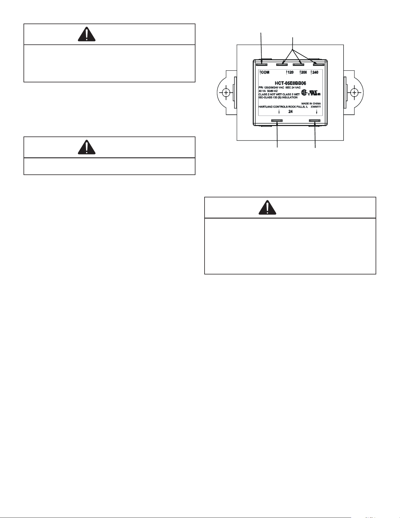
voltage is supplied to EEV cased coil control board from
transformer supply terminals. See Figure 12. For appropriate
wiring identication and installation for the cased coil, refer
to the provided wiring schematic located on the PCB control
panel cover.
EEV Cased Coil 24 VAC
supply voltage
Select single appropriate
power supply
Connect COM to
field common.
Figure 12
The cased coil PCB must be supplied 24 VAC supply voltage
from an appropriately powered transformer. A transformer
has been included with the cased coil.
WARNING
This unit is designed to operate on 24 VAC from provided
transformer. NEVER connect high voltage (120/208/240 VAC)
to the cased coil directly or to the cased coil control board.
Doing so would result in equipment damage and/or personal
injury or death. Use designated UL certified transformer
included with coil. Do not alter or modify the transformer.
Attempting to modify or alter the transformer may result in
product damage or personal injury.
11.5 How to Install the Transformer
Furnace application requires the use of the multi-tap
(120/208/240) VAC to 24 VAC transformer. Appropriate
supply voltage for the multi-tap transformer is based on
eld wiring. Select the following components from the coil
transformer installation components:
1. Multi-tap (120/208/240) VAC to 24 VAC transformer.
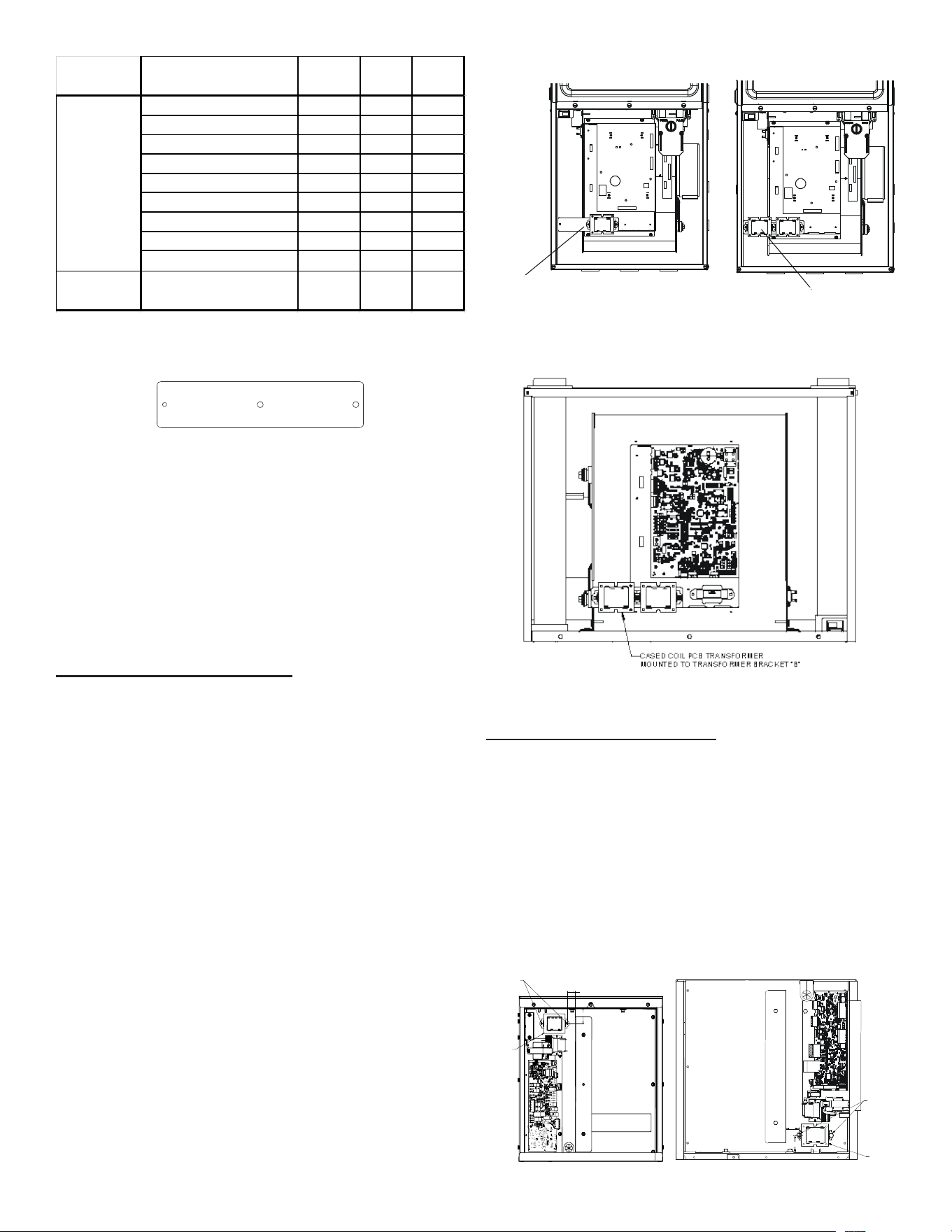
2. Appropriate PCB transformer bracket (See Table 5).
3. Supplied red/black voltage transformer power wires.
NOTE: Based in furnace or blower selection, use Table 5 to
determine appropriate PCB transformer bracket.
16
Model Name
Cabinet
Width
Bracket
B
No
Bracket
Upflow 80% All X
Upflow 96% All X
Upflow 97% All X
Upflow 80% + 96% ULN All X
Downflow 80% All X
Downflow 96% All X
Downflow 97% 17.5" X
Downflow 97% 21.0" X
Downflow 80% + 96% ULN All X
Modular
Blower
MBVK* All X
Gas Furnace
Table 5
Br ack et ‘ A ’
Br ack et ‘ B’
Figure 13
NOTE: Based on furnace or modular blower model, the
applicable bracket and PCB transformer are mounted inside
the furnace or modular blower cabinet. It is recommended
to use self tapping screws to secure the PCB transformer
and bracket plate to the mounting position. See Figure 16
through 20 to determine appropriate location.
11.5.1A Installation Bracket -”B”
Furnace transformer should be removed from the PCB
control deck. Align transformer bracket “B” and furnace
transformer to the mounting holes of the furnace transformer
on the PCB control deck. Bracket “B” should be located
between the PCB control deck and furnace transformer.
Secure innermost bracket mounting location and innermost
furnace transformer mounting hole to the PCB control deck.
Align multi-tap EEV cased coil transformer to transformer
bracket “B” by overlapping the base of furnace transformer
and securing transformers together to bracket and securing
the left side of EEV transformer, using (1) self tapping, eld
supplied screw. See Figures 16-17.
For 80 / 96 / 97% / ULN Upow Furnace
Bracket ‘B’ mounted
behind factory installed
furnace transformer
Cased Coil transformer
PCB mounted to
transformer Bracket ‘B’
Figure 16
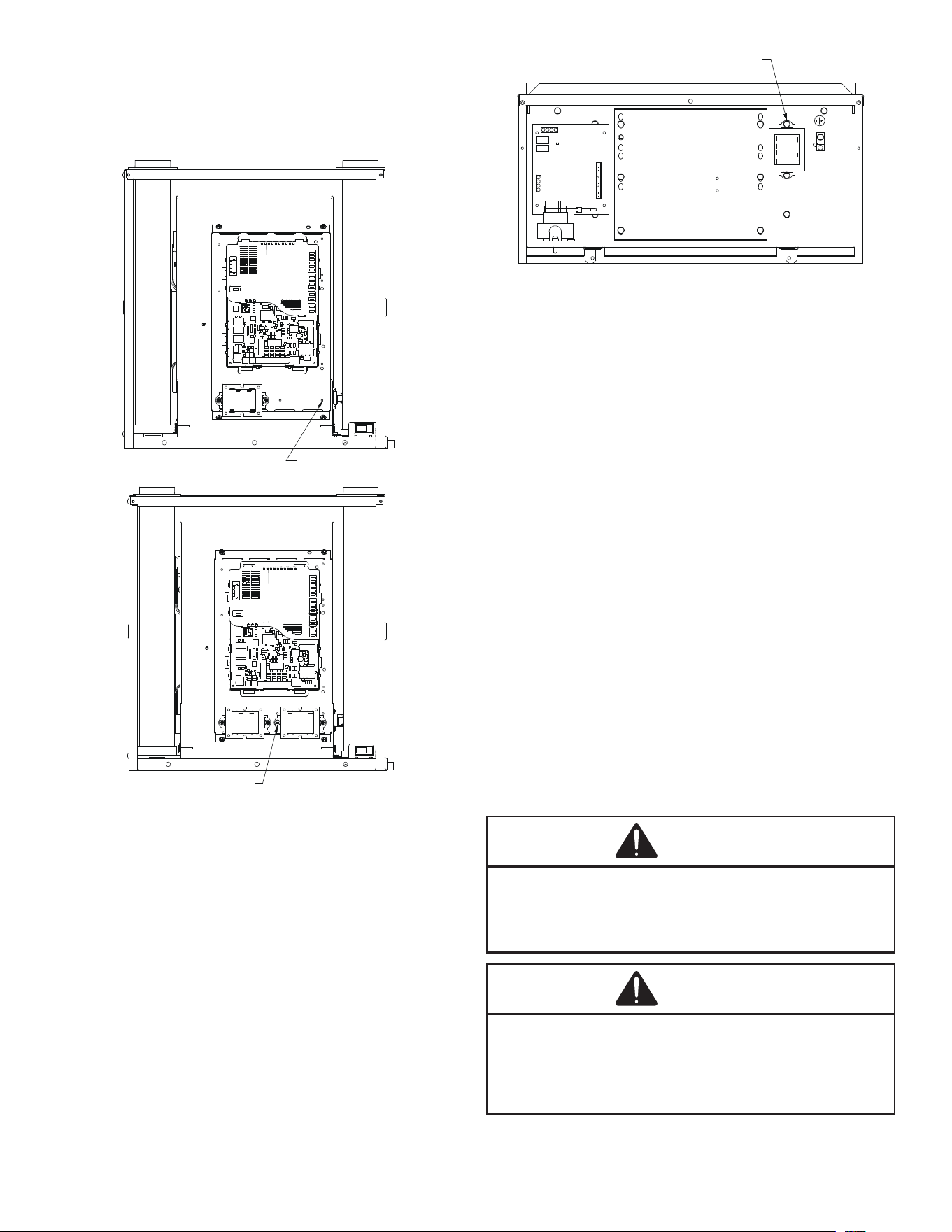
For 96% / 97% Downow Furnace (21.0” Wide Cabinet)
Figure 17
11.5.1B No Bracket Installation
For 80% Downow Furnace and Downow ULN
The PCB transformer can be assembled to the Furnace
partition plate. Fasten the PCB transformer using (2) eld
supplied self drilling screws. Locate the transformer to the
partition plate to the recommended location. See Figure 18.
The transformer should be parallel to the edge of the heat
shield. Self drilling screws should not be longer than 0.75” to
prevent interference with blower housing.
NOTE: Extreme caution must be taken when installing the
transformer to the partition plate and wiring the transformers
so as to not damage the furnace control board, wiring or
other electrical components.
1.00
1.00
FIELD SUPPLIED
SELF DRILLING
SCREWS
CASED COIL PCB
TRANSFORMER
1.75
1.25
FIELD SUPPLIED
SELF-DRILLING
SCREWS
CASED COIL PCB
TRANSFORME R
Figure 18
17
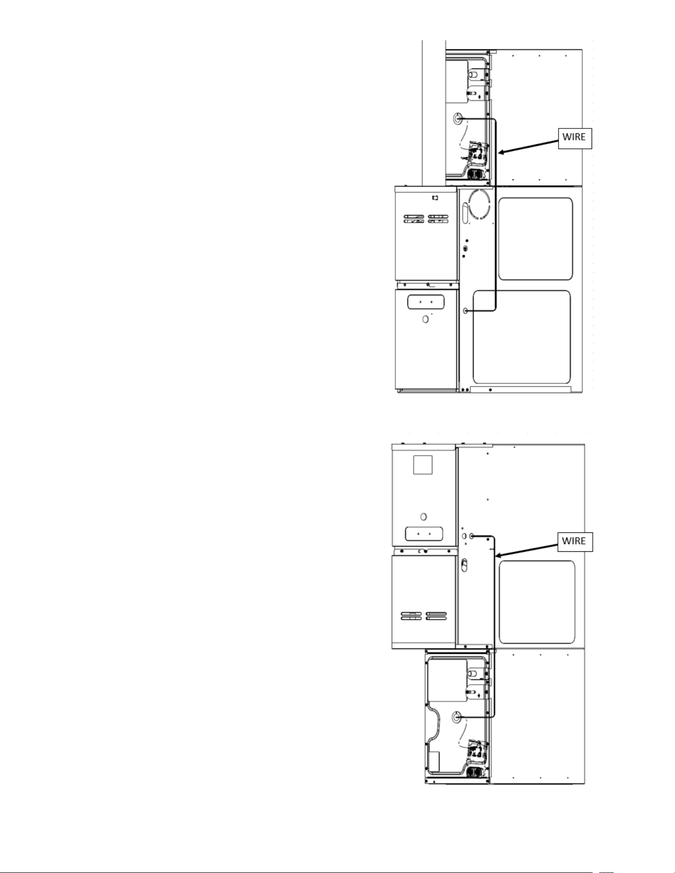
For 97% Downow Furnace (17.5” Width Cabinet)
Fasten the PCB transformer using (1) eld supplied screw
at the extras screw hole on the PCB mounting plate. Then
secure another screw hole of the PCB transformer using (1)
eld supplied, self drilling screw.
USE THIS STOCK SCREW HOLE
TIGHTEN OPPOSITE SIDE
USING (1) FIELD SUPPLIED
SELF-DRILLING SCREW
Figure 19
For the Modular Blower
Remove a screw located on the control deck that is showed
in Figure 20 and ax the PCB transformer with the removed
screw and a screw hole. Then secure another screw hole of
PCB transformer using (1) eld supplied self drilling screws.
USE THIS STOCK SCREW
Figure 20
11.6 Wiring Transformer and PCB
IMPORTANT: When wiring PCB power supply to PCB
transformer, an insulated bushing (eld supplied) must be
installed in the furnace or modular blower cabinet wall.
Wiring must pass through bushing to interior of cabinet.
DO NOT ALLOW WIRING TO PASS ALONG AREAS
WHERE WIRING IS EXPOSED TO ABRASIVE METAL
EDGES. DO NOT ALTER BLOWER DECK.
To power PCB transformer: Use high voltage red and black
wires provided in transformer installation components. Route
red/black transformer power supply to PCB transformer
from eld wiring. Power and ground wiring for cased coil:
Use accompanied yellow, purple and green wiring harness.
Communication wiring: Use accompanied black, grey, red
and blue wire harness.
DO NOT POWER TO TR1/TH1 TERMINAL OF PCB WITH
FACTORY INSTALLED FURNACE R/C THERMOSTAT
POWER INSTEAD OF PCB TRANSFORMER.
NOTE: Create wire trap on outside of cabinet wall before
passing into cabinet. The wire trap must remain below the
insulated wire bushing location to prevent moisture intrusion
into furnace or modular blower cabinet and onto electrical
components.
CAUTION
Outside the cased coil, do not route transmission wiring
together with other electrical wiring. Keep the transmission
wiring at least 2 in. (50mm) away from the power wiring and
other electrical wiring. Effects of electrical interference
(external noise) may result in malfunction and breakdown.
WARNING
Use only specified wire and connect to terminals tightly. Be
careful that wires do no place external stress on terminals.
Keep wire in neat order; not to obstruct other equipment.
Make sure that the control panel cover is closed tightly.
Incomplete connections could result in overheating, and in
worse cases, electrical shock or fire.
18
11.7 Sensor and Accessory Wiring
Refer to Table 2 for minimum conditioned room area
requirements.
R-32 sensor fault codes should be referenced through the
corresponding R-32 equipped furnace or accessory IO
manuals. It is the installer’s responsibility to ensure that
mitigation mode is operational. A test can be performed
after installation to ensure that this is the case.
Sensor is not intended for service or repair. If the sensor is
not functioning properly, mitigation mode will engage and
the sensor must be replaced by removing the old sensor
from the bracket and re-installing with new push-pins and
a zip-tie. The R-32 sensor shall only be replaced with
sensor specied by the appliance manufacturer. (Sensor
replacement part can be determined through the homeowner
support line provided earlier in the document.)
All wiring installed in the eld to be used in conjunction with
the sensor must meet the following minimum specication:
• 18 AWG
• 1.58mm insulation thickness or protected from damage
The R-32 sensor must be installed and powered for service.
Ensure that the grommet is installed through the access
panel knockout hole. Sensor bracket assemblies are
shipped with two zip-ties, one of which is designed for strain
relief. This zip-tie must be kept attached to bracket and
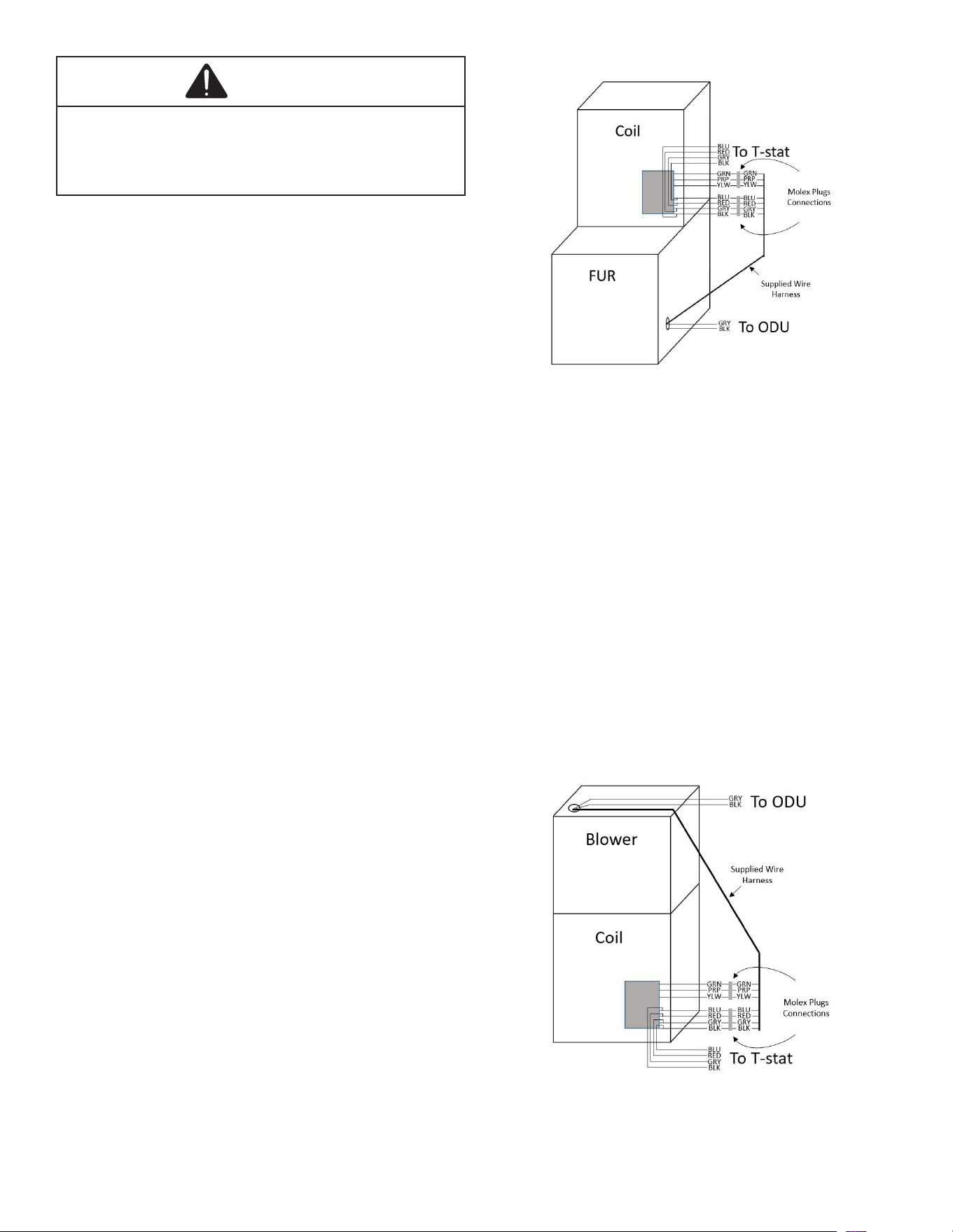
wiring. Follow routing diagram as shown in Figure 25 or 26
depending on orientation of install. This wiring is intended to
be passed through the access hole on the furnace. If a hole
must be cut in to the furnace, ensure that the wiring is well
protected from mechanical damage and that the hole is free
from burrs or sharp edges. Utilize a protective coating for all
exposed metallic edges.
Check for the wiring diagram as seen at the end of this
manual. If the sensor used in this unit must be routed
through the Non-A2L Furnace Integration Kit, then reference
the Non-A2L Furnace Integration Kit installation manual for
further instructions.
For any and all accessories which may become a potential
ignition source, they must be installed to an AUX port on
either the furnace or Non-A2L Furnace Integration Kit. Ensure
that any additional wiring from the cased coil is done so as
to protect from damage and wear, avoiding the ue pipe and
any joints which may need to be brazed or disconnected for
service. If a zone controller must be powered through a zone-
control kit to ensure that the zoning dampers actuate during
mitigation mode. Refer to the product specication sheet for
the zoning and the accessory control kit part number.
Check that wiring will not be subject to wear, corrosion,
excessive pressure, vibration, sharp edges or any other
adverse environmental eects. The check shall also take
into account the eects of aging or continual vibration from
sources such as compressors or fans.
Figure 25 - Upow Wire Routing
Figure 26 - Downow Wire Routing
19
WARNING
When installing the wiring, make sure that wiring is neat
and does not touch sharp edge of sheet metal and does not
cause the control panel to stick up, and then close the cover
firmly. When attaching the control cover, make sure you do
not pinch any wires.
12 FULLY COMMUNICATING SYSTEM
12.1 Overview
The Communicating system is a system that includes a
Communicating compatible cased coil and outdoor unit with
a communicating thermostat. System may ONLY be installed
using an approved communicating thermostat.
A Communicating heating/air conditioning system diers
from a non-communicating/traditional system in the manner
in which the indoor unit, outdoor unit and thermostat interact
with one another. In a traditional system, the thermostat
sends commands to the indoor and outdoor units via analog
24 VAC signals. It is a one-way communication path. The
indoor and outdoor units typically do not return information
to the thermostat.
On the other hand, the indoor unit, and thermostat comprising
a Communicating system “communicate” digitally with
one another. It is now a two-way communications path.
The thermostat still sends commands to the indoor and
outdoor units and may also request and receive information
from both the indoor and outdoor units. This information
may be displayed on the Communicating thermostat. The
indoor and outdoor units also interact with one another. The
outdoor unit may send commands to or request information
from the indoor unit. This two-way digital communications
between the thermostat and subsystems (indoor/outdoor
unit) is the key to unlocking the benets and features of the
Communicating system.
12.2 Wire Harness Instructions
For proper installation and to achieve a stable communication
network, we strongly recommend to install the wire harness
components that comes in the cased coil literature bag.
A) Wire Harness for Furnace Installation with Cased Coil
1. Make sure power is o to equipment
2. Remove Wire Harness from Literature bag.
3. Connect male Molex Plugs on the Wire Harness to
female Molex Plugs coming from the control box on
the cased coil.
4. Route eld supplied data wires for the outdoor unit
and the harness’s thermostat wiring through the
furnace wire grommet.
5. Connect wires to the furnace phoenix connector
before inserting onto the PCB slot, matching
terminals 1, 2, R, C.
6. Run the harnesses low voltage wiring (yellow, purple,
and green) through the furnace wire grommet to the
additional transformer inside the furnace cabinet.
7. Run the harnesses low voltage wiring (blue, red, gray
and black) through the cased coil wire grommet to
the thermostat.
8. View Figure 21 for reference of Wire Harness Setup.
Figure 21
B) Wire Harness for Modular Blower Installation with
Cased Coil
1. Make sure power is o to the equipment
2. Remove Wire Harness from Literature bag.
3. Connect male Molex Plugs on the Wire Harness to
female Molex Plugs coming from the control box on
the cased coil.
4. Route eld supplied data wires for the outdoor unit
and the harness’s thermostat wiring through the
modular blower’s wire grommet.
5. Connect wires to the blower phoenix connector
before inserting onto the PCB slot, matching
terminals 1, 2, R, C.
6. Run the harnesses low voltage wiring (yellow, purple,
and green) through the blower wire grommet to the
additional transformer inside the blower cabinet.
7. Run the harnesses low voltage wiring (blue, red, gray
and black) through the cased coil wire grommet to
the thermostat.
8. View Figure 22 for reference of Wire Harness Setup.
Figure 22
12.3 Thermostat Wiring
NOTE: Refer to section 11. ELECTRICAL WIRING WORK
for 24 volt line connections to the cased coil.
20
NOTE: Only use approved communicating thermostats.
Approved communicating thermostats are Daikin ONE+
smart thermostat, and Amana® brand smart thermostat.
NOTE: A plug connector is provided with the control to make
thermostat wire connections. Wire nuts are recommended
to ensure one wire is used for each terminal. Failure to do
so may result in intermittent operation.
Typical 18 AWG thermostat wire may be used to wire the
system components. However, communications reliability
may be improved by using a high quality, shielded, twisted
pair cable for the data transmission lines.
12.4 Two-Wire Outdoor and Four-Wire Indoor Wiring
Typical wiring will consist of two wires between the indoor
unit and outdoor unit and four wires between the indoor unit
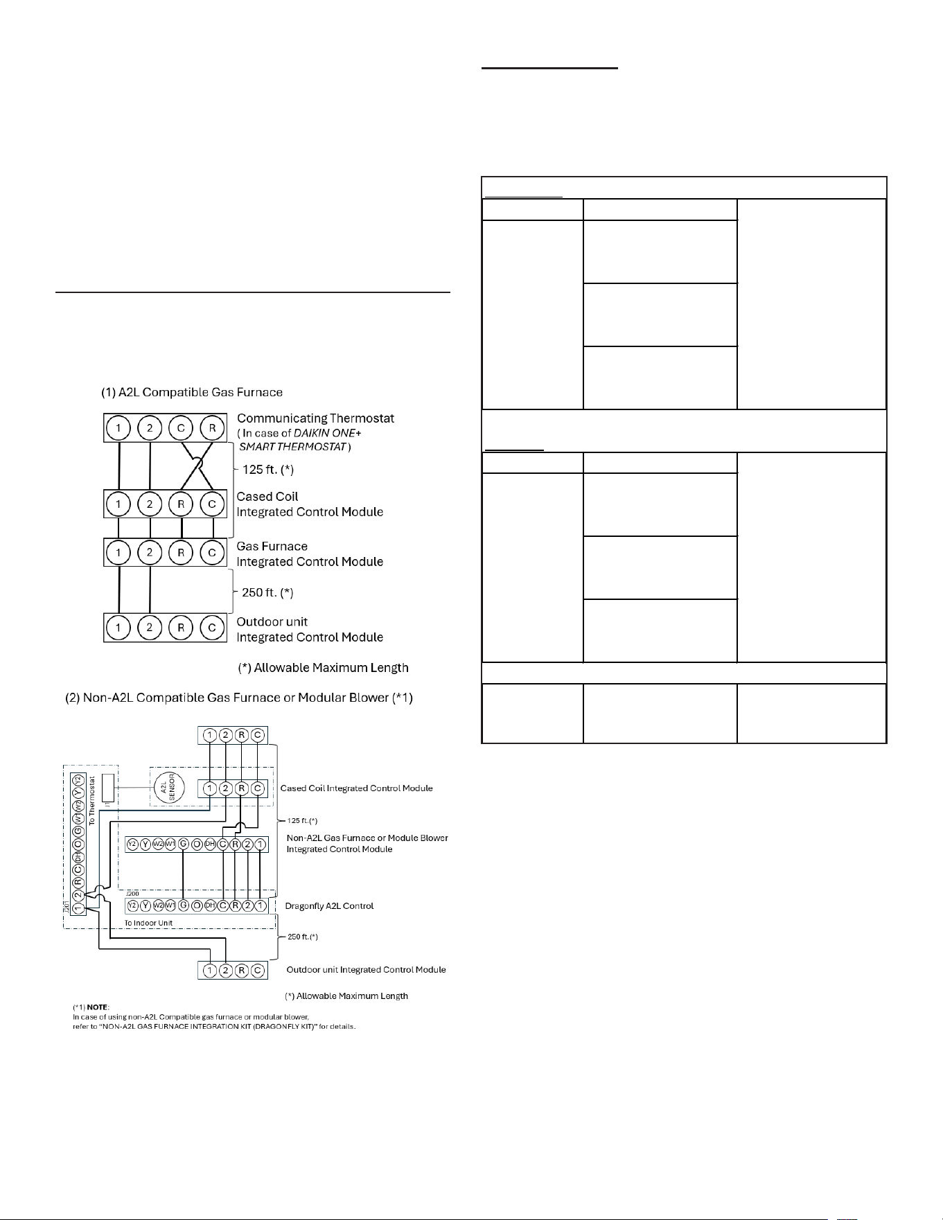
and thermostat. Figure 23 shows the required wires are: data
lines, 1 and 2; “R” (24 VAC hot) and “C” (24 VAC common).
Communicating Thermostat
(In case of Daikin One+ Smart Thermostat)
Figure 23 - System Wiring
12.5 Airflow Trim
Indoor airow can be trimmed up/down through the outdoor
unit user menu. For more detailed information, please refer
to the outdoor unit installation manual.
NOTE: Trim Setting of the following combinations are
restricted.
For R410-A
Outdoor Unit 3 Ton
G*VC800803B
A*VC800803B
D*80VC0803B
G*VC960403B/603B
A*VC960403B/603B
D*96VC0403B/603B
G*VM970603B
A*VM970603B
D*97MC0603B
For R-32
Outdoor Unit 3 Ton
G*VT800803B
A*VT800803B
D*80TC0803B
G*VT960403B/603B
A*VT960403B/603B
D*96TC0403B/603B
G*VM970603B
A*VM970603B
D*97MC0603B
Modular
Blower
MBVK12BP1X0
Trim settings higher
than 10% are not
allowed.
Indoor Unit
Trim settings higher
than 10% are not
allowed.
Indoor Unit
Trim settings higher
than 10% are not
allowed.
13 MISCELLANEOUS START-UP
CHECKLIST
• Prior to start-up, ensure that all electrical wires are
properly sized and all connections are properly
tightened.
• Tubing must be leak free.
• Condensate line must be trapped and pitched to
allow for drainage.
• Auxiliary drain is installed when necessary and
pitched to allow for drainage.
• Low voltage wiring is properly connected.
• Unit is protected from vehicular or other physical
damage.
• Return air is not obtained from, nor are there any
return air duct joints that are unsealed in areas where
there may be objectionable odors, ammable vapors
or products or combustion such as carbon monoxide
(CO), which may cause serious personal injury or
death.
21
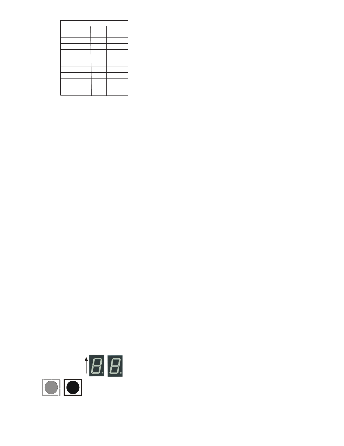
Model Name Upflow Downflow
CAPEA2418B3* 910 910
CAPEA2418C3* 910 910
CAPEA3022B3* 1160 1160
CAPEA3022C3* 1160 1160
CAPEA3626B3* 1450 1260
CAPEA3626C3* 1450 1260
CAPEA3626D3* 1450 1450
CAPEA4830C3* 1520 1450
CAPEA4830D3* 1520 1450
CAPEA6030C3* 1890 1890
CAPEA6030D3* 1890 1890
MAXIMUM ALLOWED CFM
14 TROUBLESHOOTING
14.1 Electrostatic Discharge (ESD) Precautions
NOTE: Discharge your body’s static electricity before
touching unit. An electrostatic discharge can adversely
aect electrical components.
Use the following precautions during cased coil installation
and servicing to protect the integrated control module
from damage. By putting the cased coil, the control, and
the person at the same electrostatic potential, these steps
will help avoid exposing the integrated control module to
electrostatic discharge. This procedure is applicable to both
installed and uninstalled (ungrounded) cased coils.
1. Disconnect all power to the whole system. Do not
touch the integrated control module or any wire
connected to the control prior to discharging your
body’s electrostatic charge to ground.
2. Firmly touch a clean, unpainted, metal surface of
the cased coil near the control. Any tools held in a
person’s hand during grounding will be discharged.
3. Service integrated control module or connecting
wiring following the discharge process in step 2.
Use caution not to recharge your body with static
electricity; (i.e., do not move or shue your feet, do
not touch ungrounded objects, etc.) If you come in
contact with an ungrounded object, repeat step 2
before touching control or wires.
4. Discharge your body’s electrostatic charge to ground
before removing a new control from its container.
Follow steps 1 through 3 if installing the control
on a unit. Return any old or new controls to their
containers before touching any ungrounded object.
14.2 Diagnostic Chart
Refer to the Troubleshooting Chart on the following page
for assistance in determining the source of unit operational
problems. The 7 segment LED display will provide any
active fault codes.
7 Segment
Diagnostic
Displays
Fault
Recall
Figure 24
14.3 Fault Recall
The integrated control module is equipped with a momentary
push-button switch that can be used to display the last six
faults on the 7 segment LED display. Follow sequence
below to use the feature. The control must be in Standby
Mode (no thermostat inputs).
1. Press FAULT RECALL button for 2 to 5 seconds*, so
that 7 segment displays show “- -”.
2. Release FAULT RECALL button in this period, 7
segment displays show the most recent fault.
3. Each time FAULT RECALL button is pressed after
that**, 7 segment displays output next occurred fault.
4. After displaying the series of recent faults, 7 segment
displays blink “- -” and goes back to Standby Mode.
To clear the error code history:
1. Press FAULT RECALL button for 10 to 15
seconds***, so that 7 segment blinks “- -”.
2. Release FAULT RECALL button in this period, 7
segment displays shows “88” and faults are cleared.
NOTE:
* If the FAULT RECALL button is not pressed long enough
(2 to 5 seconds), control goes back to Standby Mode.
If the FAULT RECALL button is pressed for 5 to 10 seconds,
the control goes back to Standby Mode.
** Consecutively repeated faults are displayed a maximum
of three times.
*** If FAULT RECALL button is pressed for longer than 15
seconds, control goes back to Standby Mode.
14.4 Network Troubleshooting
The Communicating system is a full communicating system,
constituting a network. Occasionally the need to troubleshoot
the network may arise. The integrated cases coil control has
some onboard tools they are, red communications LED,
green receive (Rx) LED, and the learn button. Refer to the
Communications Troubleshooting Chart on the following
page for the error codes, possible causes and corrective
actions.
• Red communications LED - indicates the status of
the network. The Communications Troubleshooting
Chart on the following page indicates the LED status
and the corresponding potential problem.
• Green receive LED - indicates network trac. The
following table indicates the LED status and the
corresponding potential problem.
• Learn button - used to reset the network. Depress
the button for greater than 5 seconds to reset the
network.
14.5 System Troubleshooting
NOTE: Refer to the instructions accompanying the
Communicating compatible outdoor unit for unit specic
troubleshooting information. Refer to the Troubleshooting
Chart for the following page for a listing of possible cased
coil error codes, and possible causes and corrective actions.
Under no circumstances shall potential sources of ignition
be used in the searching for or detection of refrigerant leaks.

22
A halide torch (or any other detector using a naked flame)
shall not be used. If a leak is suspected, all naked flames
shall be removed/extinguished. If a leakage of refrigerant is
found which requires brazing, all of the refrigerant shall be
recovered from the system, or isolated (by means of shut o
valves) in a part of the system remote from the leak.
The following leak detection methods have been deemed
acceptable, provided proper care is taken in their
implementation:
1. Electronic leak detectors rated for use with R32
refrigerant. Ensure the detection equipment is calibrated
in a refrigerant-free area and that the leak detector itself
is not a potential source of ignition. Leak detection
equipment shall be set at a value of no more then 0.075
kg/m3.
2. Leak detection fluids - such as the bubble method or
fluorescent method. Ensure that the use of detergents
containing chlorine are avoided as they chlorine may
react with the refrigerant and corrode the pipe-work.
Do not apply any permanent inductive or capacitance loads
to the circuit without ensuring that this will not exceed the
permissible voltage and current permitted for the equipment
in use.
Check that cabling (wiring) will not be subjected to wear,
corrosion, excessive pressure, vibration, sharp edges or any
other adverse environmental eects. The check shall also
take into account the eects of aging or continual vibration
from sources such as compressors or fans.
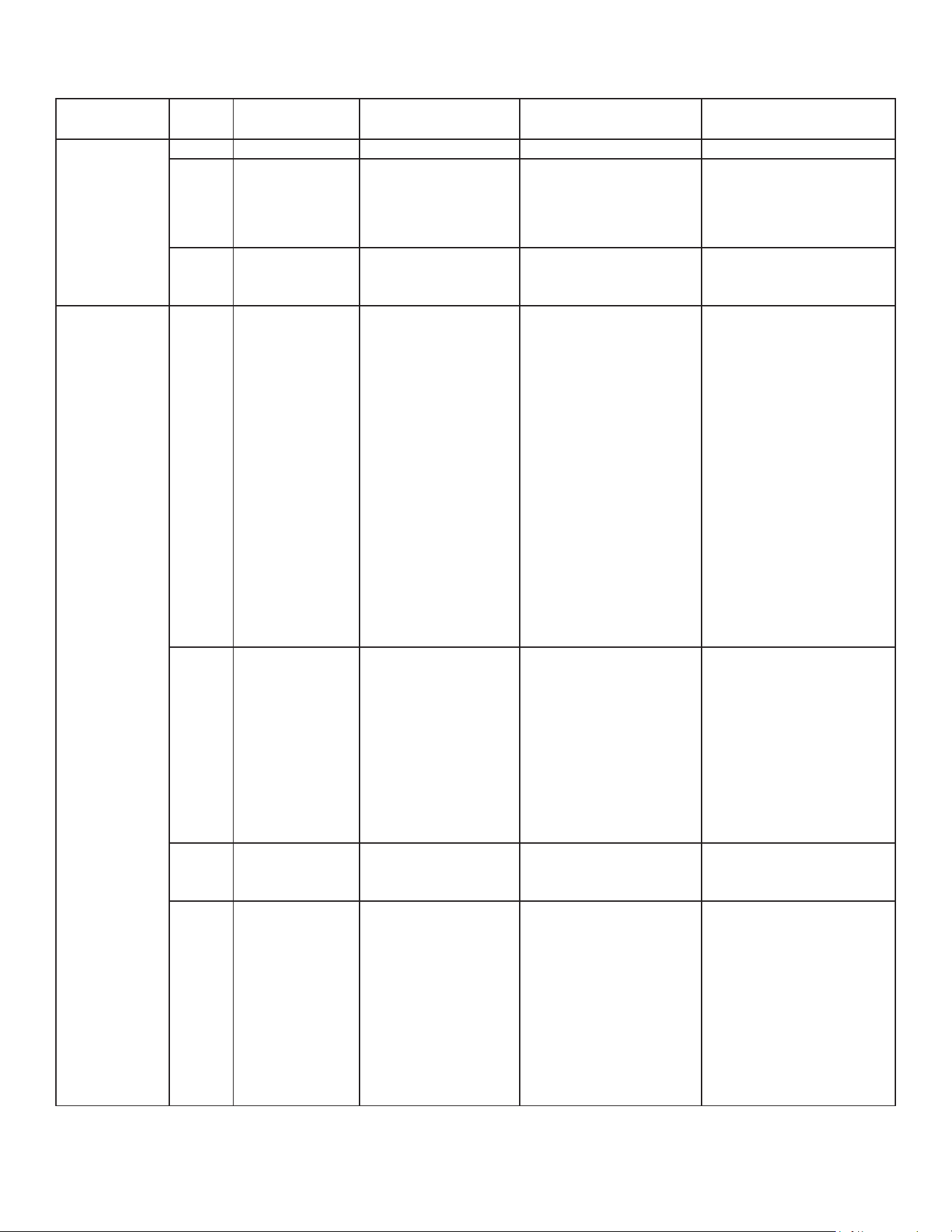
23
COMMUNICATIONS TROUBLESHOOTING CHART
LED
LED
Status
Indication Possible Causes Corrective Action(s) Notes & Cautions
Red
Communications
LED
O • None • None • None • None
1
Flash
• Communications
Failure
• Communications
Failure
• Depress Learn Button
• Verify wiring connection
• Depress once quickly for a
power-up reset
• Depress and hold for 5
seconds for an out-of-box
reset
2
Flashes
• Out-of-box reset • Control power up
• Learn button
depressed
• None • None
Green
Receive
LED
O
• No power
• Communications
error
• No power to
cased coil
• Open fuse
• Communications
error
• Check fuses and circuit
breakers; replace/reset
• Replace blown fuse
• Check for shorts in low
voltage wiring in cased
coil/system
• Reset network by
depressing learn button
• Check data 1/data 2
voltages
• Typically the data 1
line is approximately
2.8 VDC and the data
2 transmission line is
approximately 2.2 VDC.
The voltage dierence
between data 1 and data
2 must be 0.6 VDC.
• Turn power OFF prior to
repair
1 Steady
Flash
• No network
found
• Broken/ disconnected
data wire(s)
• Cased coil is
installed as a non-
communicating/
traditional system
• Check communications
wiring (data 1/data 2
wires)
• Check wire connections
at terminal block
• Verify cased coil
installation type (non-
communicating/traditional
or communicating)
• Check data 1/data 2
voltages
• Turn power OFF prior to
repair
• Verify wires at terminal
blocks are securely twisted
together prior to inserting
into terminal block
• Verify data 1 and data
2 voltages as described
above
Rapid
Flashing
• Normal network
trac
• Control is "talking" on
network as expected
• None • None
On Solid
• Data 1/Data 2
miss-wire
• Data 1/data 2 wires
reversed at cased
coil, thermostat,
or Communicating
compatible outdoor
unit
• Short between data 1/
data 2 wires
• Short between data 1
or data 2 wires and R
(24VAC) or C (24VAC
common)
• Check communications
wiring (data 1/data 2
wires)
• Check wire connections
at terminal block
• Check data 1/data 2
voltages
• Turn power OFF prior to
repair
• Verify wires at terminal
blocks are securely twisted
together prior to inserting
into terminal block
• Verify data 1 and data
2 voltages as described
above
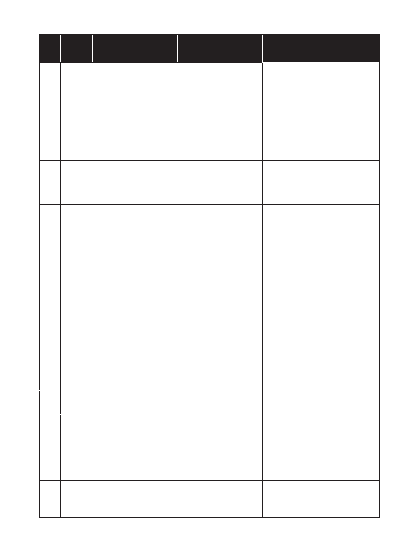
24
TROUBLESHOOTING
Error
CODE
PCB LED
DISPLAY
ClimateTalk
MESSAGE
DESCRIPTION POSSIBLE CAUSES CORRECTIVE ACTIONS
EE
No display
(EE display is
EMG mode)
INTERNAL
FAULT
• No 24 volt power
to PCB
• Blown fuse or
circuit breaker
• PCB has an
internal fault
• Manual disconnect switch OFF
• No 24 volt power to PCB
• Blown fuse or faulty circuit breaker
• Control board has internal fault
• Assure 24 volt power to blower and control board.
Check fuse F2U on control board
• Check for possible short in 115/230 volt and 24
volt circuits. Repair as necessary.
• Replace the control board.
d0 E_d0
Data Not Yet
On Network
(NO NET DATA)
Data Not Yet
On Network
• No shared data on the network • Populate shared data set using memory card.
d4 E_d4
Invalid
Memory
Card Data
(INVALID MC
DATA)
Invalid
Memory Card
Data
• Wrong memory card data
• Replace circuit board
• Rewrite data using the correct memory card
70 E_70
EEV
OPEN CKT
EEV
disconnection
detected
• Indoor EEV coil not connected
• Incorrect wiring to EEV
• Check Indoor EEV coil connection (PCB and
junction connector)
• Replace EEV coil
• Check the resistance value of EEV coil (refer
service manual)
• Replace the control board
73 E_73 LIQ TEMP FLT
Liquid side
thermistor
abnormality
• Open (or) short circuit of the liquid
thermistor (X5A)
• Liquid thermistor reading incorrect
or values outside the normal range
• Check the connection to liquid thermistor (PCB
and junction connector)
•
Check the resistance value of the thermistor (refer
service manual)
• Replace thermistor
• Replace the control board
74 E_74 GAS TEMP FLT
Gas side thermistor
abnormality
• Open (or) short circuit of the gas
thermistor (X5A)
• Gas thermistor reading incorrect or
values outside the normal range
• Check the connection to gas thermistor (PCB and
junction connector)
•
Check the resistance value of the thermistor (refer
service manual)
• Replace thermistor
• Replace the control board
75 E_75
PRESSURE
FLT
Pressure sensor
abnormality
• Open (or) short circuit of the
Pressure Sensor (X15A)
• Pressure Sensor reading incorrect
or values outside the normal range
• Check the connection to pressure sensor (PCB
and junction connector)
• Check the output voltage of the pressure sensor
(refer service manual)
• Replace pressure sensor
• Replace the control board
76 E_76
EQUIP
COMM
LOSS
Outdoor unit -
Gas furnace or
Blower unit
communication error
(during operation)
• Open communication circuit
• Incorrect wiring between OD unit,
Gas furnace or Modular blower
• No power supply to OD unit, Gas
furnace or Modular blower
• Check for cased coil and other unit wiring.
• Replace the control board
• Check power supply to OD unit, Gas furnace or
Modular blower
77 E_77
TSTAT ID
NO COM
Indoor Unit
Thermostat
communication
error
(start-up & during
operation)
•
Incorrect wiring between ID unit and
thermostat.
• The system may have the
communication error without error
code 77 on the indoor PCB.
Follow section 14.5 SYSTEM
TROUBLESHOOTING
• Thermostat failure
• Power interruption (low voltage)
•
Check for thermostat and indoor unit wiring
• Verify the input voltage at the ID unit and
thermostat
• After recovering the system with power supply,
TSTAT ID NO COM will continue to be displayed
on the thermostat within 2 minutes.
• The error code will be cleared automatically.
• Replace control board or thermostat
• Press "LEARN" button on PCB for more than 5
seconds to reestablish network
78 E_78
CONNECT
EQUIP
Outdoor unit - Gas
furnace or Blower
unit communication
error (Startup
operation)
• Open communication circuit
• Incorrect wiring between OD unit,
Gas furnace or Modular blower
• No power supply to OD unit, Gas
furnace or Modular blower
• Check for cased coil and other unit wiring.
• Replace the control board
• Check power supply to OD unit, Gas furnace or
Modular blower
•
<Hereafter, when using “Non-A2L
Furnace Integration Kit”> See
“Communication Error”
(When using “Non-A2L Furnace
Integration Kit”) below.
•
Check if the blower of the gas furnace or blower
unit is running and the LED display on the
non-A2L Furnace Integration Kit indicates a
refrigerant leak condition and if it is determined
that there is a leak, immediately ventilate. Then,
take measures to prevent leaks.
<Hereafter, when using “Non-A2L Furnace
Integration Kit”> See “Communication Error”
(When using “Non-A2L Furnace Intergration Kit”)
below.
•
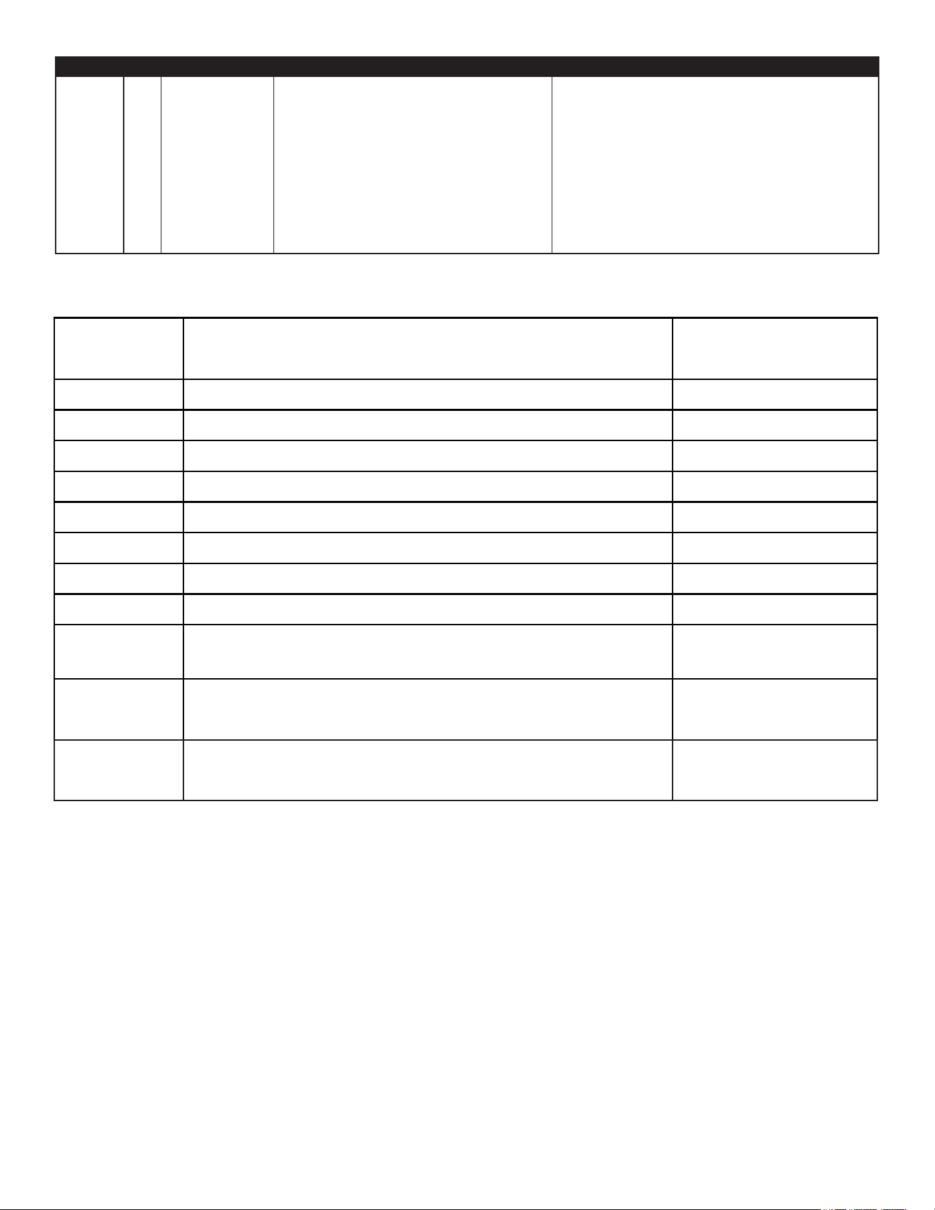
25
7 SEGMENT LED CODES
7 SEGMENT
LED DISPLAY
DESCRIPTION OF CONDITION ERROR MESSAGE
On Normal Operation --
EE EMERGENCY MODE --
d0 DATA NOT ON NETWORK Data Not Yet On Network
d4 INVALID MEMORY CARD DATA Invalid Memory Card data
70 EEV DISCONNECTION DETECTED EEV OPEN CKT
73 LIQUID SIDE THERMISTOR ABNORMALITY LIQ TEMP FLT
74 GAS SIDE THERMISTOR ABNORMALITY GAS TEMP FLT
75
PRESSURE SENSOR ABNORMALITY
PRESSURE FLT
76
CASED COIL - OUTDOOR UNIT, GAS FURNACE OR BLOWER UNIT
COMMUNICATION ERROR (DURING OPERATION)
EQUIP COMM LOSS
77
INDOOR UNIT - THERMOSTAT COMMUNICATION ERROR
(STARTUP OPERATION & DURING OPERATION)
TSTAT ID NO COM
78
CASED COIL - OUTDOOR UNIT, GAS FURNACE OR BLOWER UNIT
COMMUNICATION ERROR (STARTUP OPERATION)
CONNECT EQUIP
Items below are messages only displayed on the thermostat screen.
communication
error
-
The thermostat cannot
communicate with other
units.
• Communication wiring disconnected.
<Hereafter, when using “NON A2L FURNACE INTEGRATION KIT”>
• A2L sensor disconnected
• A2L sensor failure
• A2L refrigerant leak detection
*1) in the case of the above factors, the blower will continue to
operate.
*2) Please conrm the certain status by checking the A2L status
codes (LED) written in the installation manual of “NON A2L
FURNACE INTEGRATION KIT”.
• Check communication wiring, Repair as needed.
<Hereafter, when using “NON A2L FURNACE INTEGRATION KIT”>
*Ventilate the room before conducting any actions as needed.
• Check refrigerant leakage; Repair as needed.
• Check the connection of A2L sensor.
• Check the input voltage of A2L sensor (refer to service manual);
Replace A2L sensor or control board as needed.
*After the above failure is resolved, the error will be restored in about 10 minutes.
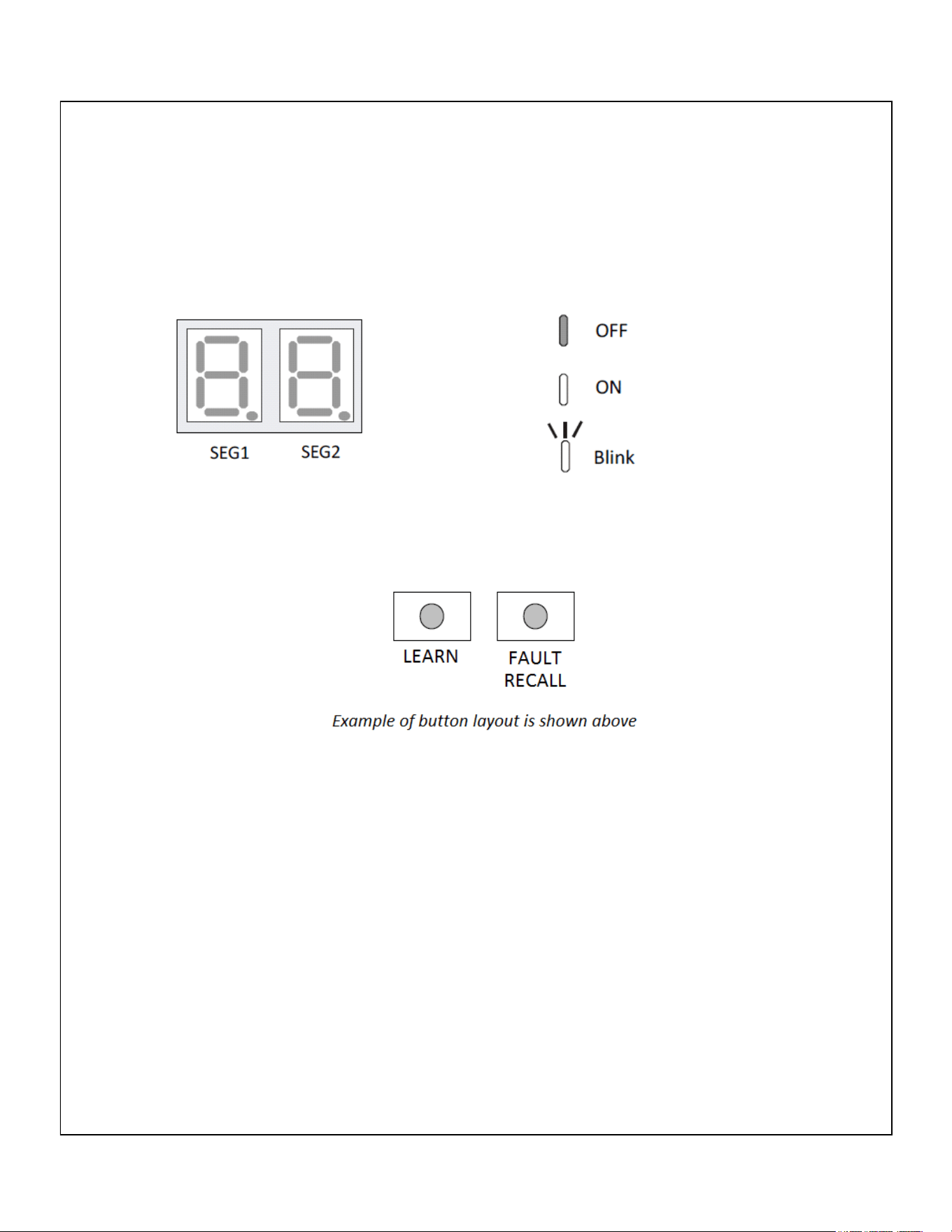
26
SETTING THE MODE DISPLAY
MODE DISPLAY INTRODUCTION
A 2-digit display is provided on the printed circuit board (PCB) as a backup tool to the
thermostat for accessing error codes and erasing error code history of the indoor unit. Follow the
information provided in this section to learn how to use the mode display
DISPLAY
The display consists of 2 digits.
DISPLAY BUTTON LAYOUT
The display buttons shown can be used to navigate and select items:
FAULT CODE HISTORY NAVIGATION
This mode will allow the user to see the six most recent system faults. Please follow the flow chart to
navigate to error codes from screen zero.
For a list of the fault codes, please see the TROUBLESHOOTING tables in this document.
It is also possible to erase all the diagnostics codes from this menu.
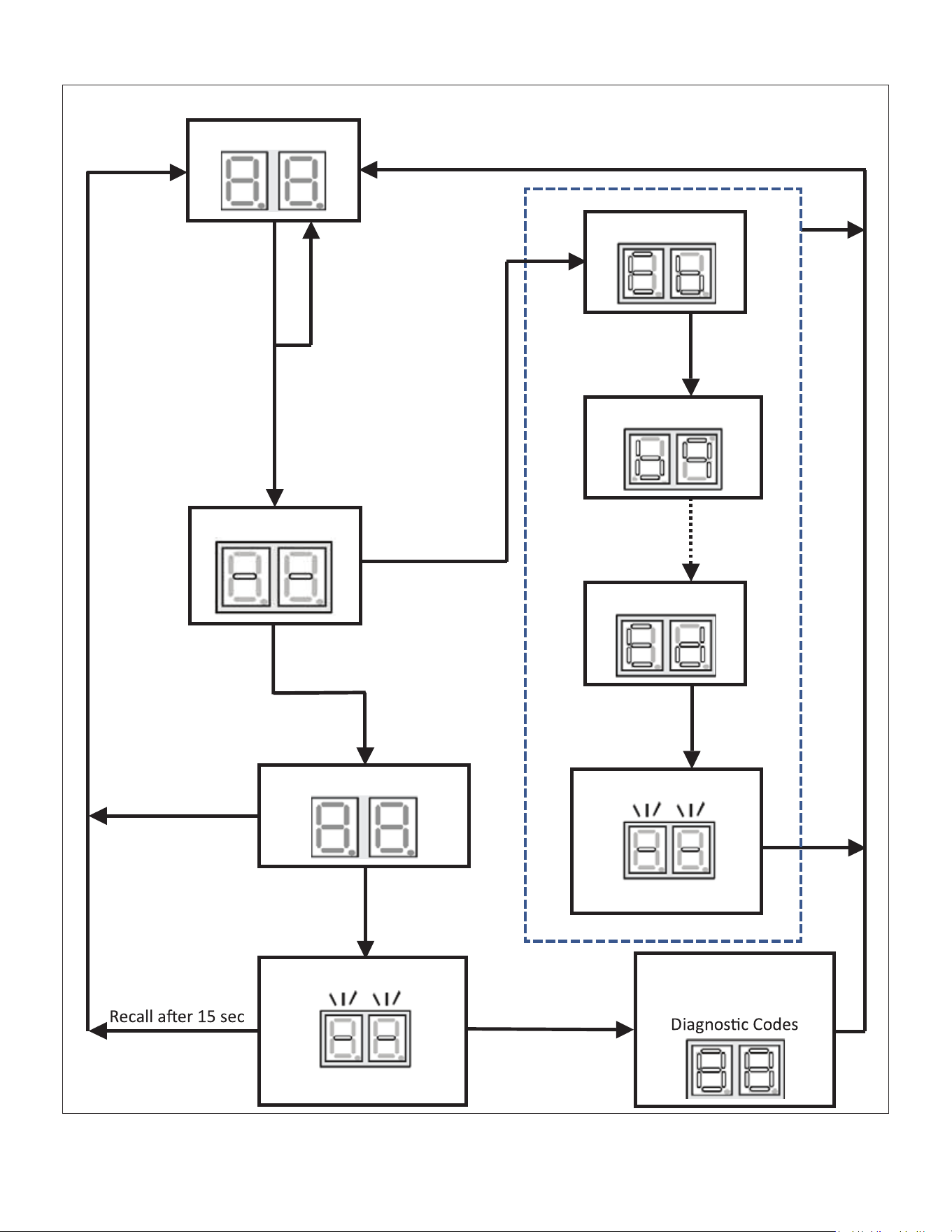
27
TROUBLESHOOTING
<SCREEN ZERO>
Release Fault
Recall in between
5 to 10 sec
Release Fault
Recall in between
10 to 15 sec
Release Fault
Hold Fault Recallf or
more than 10 sec
Solid Display
<SCREEN ZERO>
Hold Fault
Recall for more
than 2 sec
Release Fault
Recall between 2
to 5 sec
Hold Fault
Recall for more
than 5 sec
Flashing Display
First Error Code
Last Error Code
Press Fault Recall
for Error Code
Press Fault Recall
for Error Code
Press Fault Recall
to complete list
Release Fault
Recall in less
than 2 sec
Flashing Display
Solid Display “88” for
3 sec before erasing all
Second Error Code
0.2 sec ON –0.2 sec OFF
0.5 sec ON –0 .25 sec OFF
Idle
for
3
mins.
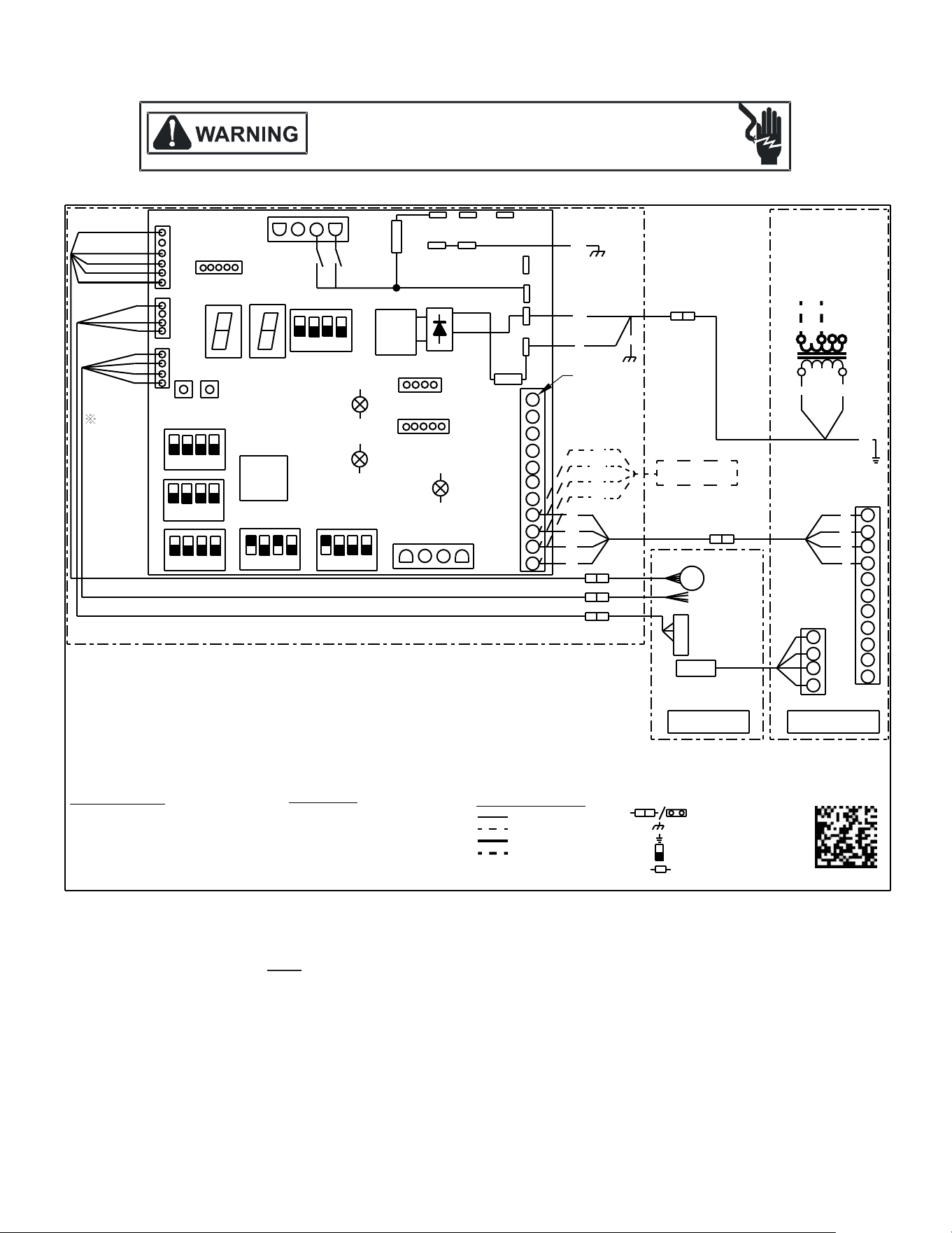
28
WIRING DIAGRAM
Wiring is subject to change. Always refer to the wiring diagram on the unit for the most up-to-date wiring.
NOTE: THESE INSTRUCTIONS ARE SPECIFICALLY
FOR CAPEA MODELS. DO NOT ATTEMPT TO APPLY
THESE DIAGRAMS TO ANY OTHER MODELS.
HIGH VOLTAGE!
D
ISCONNECT
ALL
POWER
BEFORE
SERVICING
OR
INSTALLING
THIS
UNIT
.
M
ULTIPLE
POWER
SOURCES
MAY
BE
PRESENT
. F
AILURE
TO
DO
SO
MAY
CAUSE
PROPERTY
DAMAGE
,
PERSONAL
INJURY
OR
DEATH
.
INTEGRATION
TYPE
TH1
TR1
TB4
TB5
DS2
DS3
PRESSURE
SENSOR
0140D00306-A
X3A
BS1
X12A
X13A
X8A
THERMISTOR
(HEAT
EXCHANGER 1,2)
MPU
FLASH
WRITER
RX LED
(SEE NOTE 5)
DS1
X5A
W2
W1
G
Y1
1
2
R
C
X15A
ON
OFF
2
R
1
INSIDE CONTROL BOX
INSIDE FURNACE
OR BLOWER UNIT
24VAC
COM
208
VAC
230
VAC
TR
(SEE
NOTE 1)
120
VAC
115/208/230VAC
60 Hz
DS4
DS5
BS2
FAULT RECALL
(SEE NOTE 4)
THERMISTOR
(HEAT
EXCHANGER 1,2)
CPU LED
LEARN
(SEE NOTE 4)
RAM MONITOR
O
Y2
SEG2
SEG1
DS6
TB3
X2A
PS
F2U
TB2
TB1
F1U
DATA SHARE
COMMUNICATION
WIRING
EEV
WIRING
S21
STATUS LED
(SEE NOTE 5)
DEHUM
(SEE NOTE 7)
HAP
H2P
H3P
X7A
K1R
K2R
X1A
S22
S23
S24
S1 S2 S3 S4
S5 S6 S7 S8
S9 S10 S11 S12 S13 S14 S15 S16 S17 S18 S19 S20
COM
TR2
TH2
TB10
TB8
ACC-OUT
ACC-IN
TB6
TO THERMOSTAT
5V
(SEE NOTE 8)
COMPONENT CODES
COM COMMON
DEHUM DEHUMIDIFICATION
DS1-DS6 SELECTOR SWITCH
EEV ELECTRONIC EXPANSION VALVE
F1U, F2U FUSELINK
GND GROUND
PU
GR
YL
GR
TB7
BK
RD
BK
RD
GY
BL
BK
RD
GY
BL
GR
PU
YL
BK BLACK
BL BLUE
BR BROWN
GR GREEN
GY GRAY
OR ORANGE
PU PURPLE
RD RED
WH WHITE
YL YELLOW
COLOR CODES
LOW VOLTAGE
LOW VOLTAGE FIELD
HIGH VOLTAGE
HIGH VOLTAGE FIELD
TERMINAL
PLUG CONNECTION
EQUIPMENT GROUND
FIELD GROUND
DIP SWITCH (OFF)
ON
OFF
FACTORY/FIELD WIRING
NOTES:
1. MANUFACTURER'S SPECIFIED REPLACEMENT PARTS MUST BE USED WHEN SERVICING.
2. IF ANY OF THE ORIGINAL WIRES AS SUPPLIED WITH THIS UNIT MUST BE REPLACED, IT MUST BE REPLACED
WITH WIRING MATERIAL HAVING A TEMPERATURE RATING OF AT LEAST 105
°C. USE COPPER CONDUCTORS ONLY.
3. UNIT MUST BE PERMANENTLY GROUNDED AND THE INSTALLATION MUST COMPLY WITH N.E.C AND LOCAL CODES.
4. TO RECALL THE LAST 6 FAULTS, MOST RECENT TO LEAST RECENT, DEPRESS FAULT RECALL BUTTON FOR MORE
THAN 2 SECONDS WHILE IN STANDBY (NO THERMOSTAT INPUTS). USE LEARN BUTTON TO RESET NETWORK.
5. RED STATUS LED PROVIDES NETWORK STATUS, GREEN RX LED INDICATES NETWORK TRAFFIC.
6. THE POSITION OF SELECTOR SWITCHES (DS1 - DS6) INDICATE FACTORY SETTING.
7. SELECTION OF CORRECT SUPPLY VOLTAGE FOR TRANSFORMER DEPENDS ON POWER SUPPLY VOLTAGE TO
GAS FURNACE OR BLOWER UNIT.
8. USE N.E.C CLASS 2 WIRE.
INSIDE CABINET
OF COIL
R-32
SENSOR
PRESSURE
SENSOR
EEV COIL
BK
GY
RD
BL
C
1
2
GND
29
CASED COIL
CASED COIL HOMEOWNER’S ROUTINE MAINTENANCE RECOMMENDATIONS
We strongly recommend a bi-annual maintenance checkup be performed before the heating and cooling seasons begin by a qualied servicer.
REPLACE OR CLEAN FILTER
IMPORTANT NOTE: Never operate unit without a lter
installed as dust and lint will build up on internal parts resulting
in loss of eciency, equipment damage and possible re.
An indoor air lter must be used with your comfort system.
A properly maintained lter will keep the indoor coil of your
comfort system clean. A dirty coil could cause poor operation
and/or severe equipment damage.
Your air lter or lters could be located in your furnace, in a
blower unit, or in “lter grilles” in your ceiling or walls. The
installer of your air conditioner or heat pump can tell you
where your lter(s) are, and how to clean or replace them.
Check your lter(s) at least once a month. When they are
dirty, replace or clean as required. Disposable type lters
should be replaced. Reusable type lters may be cleaned.
You may want to ask your dealer about high eciency lters.
High eciency lters are available in both electronic and
non-electronic types. These lters can do a better job of
catching small airborne particles.
MOTORS
Indoor and outdoor fan motors are permanently lubricated
and do not require additional oiling.
WARNING
HIGH VOLTAGE
Disconnect ALL power before servicing or
installing this unit. Multiple power sources
may be present. Failure to do so may cause
property damage, personal injury or death.
ALUMINUM INDOOR COIL CLEANING
(QUALIFIED SERVICER ONLY)
R-32 sensor must be removed from the unit before
applying coil cleaners to avoid damage and contamination.
Reassemble the R-32 sensor back in the unit after completing
the coil cleaning process. This unit is equipped with an
aluminum tube evaporator coil. The safest way to clean the
evaporator coil is to simply ush the coil with water. This
cleaning practice remains as the recommended cleaning
method for both copper tube and aluminum tube residential
evaporator coils.
It has been determined that many coil cleaners and drain
pan tablets contain corrosive chemicals that can be harmful
to aluminum tube and n evaporator coils. Even a one-
time application of these corrosive chemicals can cause
premature aluminum evaporator coil failure. Any cleaners
that contain corrosive chemicals including, but not limited to,
chlorine and hydroxides, should not be used. An alternate
cleaning method is to use one of the products listed in TP-
109* to clean the coils. The cleaners listed are the only
agents deemed safe and approved for use to clean round
tube aluminum coils.
WARNING
Do not use means to accelerate the defrosting process or to
clean, other than those recommended by the manufacturer.
The appliance shall be stored in a room without continuously
operating ignition sources (for example: open flames, an
operating gas appliance or an operating electric heater).
Do not pierce or burn. Be aware that refrigerants may not
contain an odor.
TP-109 is also available on the web site in Partner Link >
Service Toolkit.
NOTE: Ensure coils are rinsed well after use of any chemical
cleaners.
• Condensate line must be trapped and pitched to
allow for drainage.
• Low voltage wiring is properly connected.
• Auxiliary drain is installed when necessary and
pitched to allow for drainage.
• Unit is protected from vehicular or other physical
damage.
• Return air is not obtained from, nor are there any
return air duct joints that are unsealed in, areas
where there may be objectionable odors, ammable
vapors or products of combustion such as carbon
monoxide (CO), which may cause serious personal
injury or death.
• Ensure that the equipped R-32 sensor is wired to
the furnace PCB and that there are no sources of
potential ignition within the system.
CAUTION
To avoid the risk of equipment damage or fire, install the
same amperage breaker or fuse as you are replacing. If the
circuit breaker or fuse should open again within thirty days,
contact a qualified servicer to correct the problem.
If you repeatedly reset the breaker or replace the fuse
without having the problem corrected, you run the risk of
severe equipment damage.
30
BEFORE YOU CALL YOUR SERVICER
• Check the thermostat to conrm that it is properly
set.
• Wait 15 minutes. Some devices in the outdoor
unit or in programmable thermostats will prevent
compressor operation for awhile, and then reset
automatically. Also, some power companies will
install devices which shut o air conditioners for
several minutes on hot days. If you wait several
minutes, the unit may begin operation on its own.
• Check the electrical panel for tripped circuit breakers
or open fuses. Reset the circuit breakers or replace
fuses as necessary.
• Check the disconnect switch near the indoor furnace
or blower to conrm that it is closed.
• Check for obstructions on the outdoor unit. Conrm
that it has not been covered on the sides or the top.
Remove any obstruction that can be safely removed.
If the unit is covered with dirt or debris, call a
qualied servicer to clean it.
• Check for blockage of the indoor air inlets and
outlets. Conrm that they are open and have not
been blocked by objects (rugs, curtains or furniture).
• Check the lter. If it is dirty, clean or replace it.
• Listen for any unusual noise(s), other than normal
operating noise, that might be coming from the
outdoor unit. If you hear unusual noise(s) coming
from the unit, call a qualied servicer.
REFRIGERANT RECOVERY
When removing refrigerant from a system, either for
servicing or decommissioning, it is recommended good
practice that all refrigerants are removed safely. When
transferring refrigerant recovery cylinders, ensure that only
appropriate refrigerant recovery cylinders are employed.
Ensure that the correct number of cylinders for holding the
total system charge are available. All cylinders to be used
are designated for the recovered refrigerant and labeled
for that refrigerant (i.e. special cylinders for the recovery
of refrigerant). Cylinders shall be complete with pressure-
relief valve and associated shut-o valves in good working
order. Empty recovery cylinders are evacuated and, if
possible, cooled before recovery occurs.
The recovery equipment shall be in good working order
with a set of instructions concerning the equipment that
is at hand and shall be suitable for the recovery of the
ammable refrigerant. If in doubt, the manufacturer should
be consulted. In addition, a set of calibrated weighting
scales shall be available and in good working order. Hoses
shall be complete with leak-free disconnect couplings
and in good condition. The recovered refrigerant shall
be processed according to local legislation in the correct
recovery cylinder, and the relevant waste transfer note
arranged. Do not mix refrigerants in recovery units and
especially not in cylinders.
If compressors or compressor oils are to be removed,
ensure that they have been evacuated to an acceptable
level to make certain that ammable refrigerant does not
remain within the lubricant. The compressor body shall
not be heated by an open ame or other ignition sources
to accelerated this process. When oil is drained from a
system, it shall be carried out safely.
31
Air Handler / Coil
ELECTRICAL
Line Voltage (Measure L1 and L2 Voltage) L1 - L2
Secondary Voltage (Measure Transformer Output Voltage) R - C
Blower Amps
Heat Strip 1 - Amps
Heat Strip 2 - Amps
BLOWER EXTERNAL STATIC PRESSURE
Return Air Sta�c Pressure IN. W.C.
Supply Air Sta�c Pressure IN. W.C.
Total External Sta�c Pressure (Ignoring +/- from the reading above, add total here) IN. W.C.
TEMPERATURES
Return Air Temperature (Dry bulb / Wet bulb) DB °F WB °F
DB °F WB °F
Hea�ng Supply Air Temperature DB °F
Temperature Rise DB °F
Delta T (Difference between Supply and Return Temperatures) DB °F
Air Handler / Coil - (Inverter Matched)
INVERTER AH / COIL ONLY
Check EEV and EEV wiring is secure (no adjustment required)
Addi�onal Checks
°F to °C formula: (°F - 32) divided by 1.8 = °C °C to °F formula: (°C mul�plied by 1.8) + 32 = °F
Check wire rou�ngs for any rubbing
Check product for proper draining
Check screw �ghtness on blower wheel
Check factory wiring and wire connec�ons
Check product for proper clearances as noted by installa�on instruc�ons
Check R-32 sensor wiring & wire connec�ons to the corresponding furnace or Non-A2L integra�on boards
Check that mi�ga�on mode is opera�onal
Model Number
Serial Number
Cooling Supply Air Temperature (Dry bulb / Wet bulb)
START-UP CHECKLIST
32
Quality Makes the Dierence!
All of our systems are designed and manufactured with the same high quality standards regardless of size or ecien-
cy. We have designed these units to signicantly reduce the most frequent causes of product failure. They are simple
to service and forgiving to operate. We use quality materials and components. Finally, every unit is run tested before it
leaves the factory.
That’s why we know. . .There’s No Better Quality.
NOTE: SPECIFICATIONS AND PERFORMANCE DATA LISTED HEREIN ARE SUBJECT TO CHANGE WITHOUT NOTICE
Our continuing commitment to quality products may mean a change in specications without notice.
© 2024
19001 Kermier Rd., Waller, TX 77484
www.daikincomfort.com • www.goodmanmfg.com • www.amana-hac.com
is a registered trademark of Maytag Corporation or its related companies and is used under license. All rights reserved.
CUSTOMER FEEDBACK
We are very interested in all product comments.
Please ll out the feedback form on one of the following links:
Daikin Products: (https://daikincomfort.com/contact-us)
Goodman
®
Brand Products: (http://www.goodmanmfg.com/about/contact-us).
Amana
®
Brand Products: (http://www.amana-hac.com/about-us/contact-us).
You can also scan the QR code on the right for the product brand you
purchased to be directed to the feedback page.
DAIKIN
AMANA
®
BRAND
GOODMAN
®
BRAND



