Page 1For technical questions, please call 1-888-866-5797.58792
Visit our website at: http://www.harborfreight.com
Email our technical support at: [email protected]
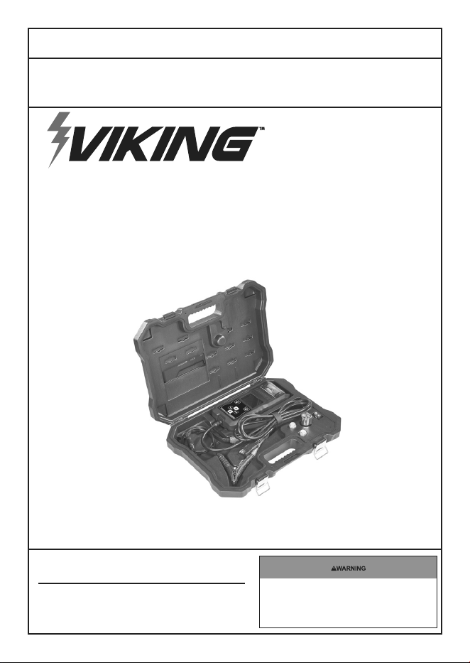
DIGITAL BATTERY
AND SYSTEM TESTER
WITH PRINTER
58792
Owner’s Manual & Safety Instructions
Save This Manual Keep this manual for the safety warnings and precautions, assembly,
operating, inspection, maintenance and cleaning procedures. Write the product’s serial number in the back
of the manual (or month and year of purchase if product has no number). Keep this manual and the receipt
in a safe and dry place for future reference. 24a
When unpacking, make sure that the product is intact
and undamaged. If any parts are missing or broken,
please call 1-888-866-5797 as soon as possible.
Copyright
©
2023 by Harbor Freight Tools
®
. All rights reserved.
No portion of this manual or any artwork contained herein may be reproduced in
any shape or form without the express written consent of Harbor Freight Tools.
Diagrams within this manual may not be drawn proportionally. Due to continuing
improvements, actual product may differ slightly from the product
described herein. Tools required for assembly and service may not be included.
Read this material before using this
product. Failure to do so can result in
serious injury. SAVE THIS MANUAL.
Page 2 For technical questions, please call 1-888-866-5797. 58792
Table of Contents
Safety .................................... 2
Specifications ........................ 4
Setup ..................................... 4
Operation ............................... 5
Maintenance ......................... 10
Warranty ............................... 12
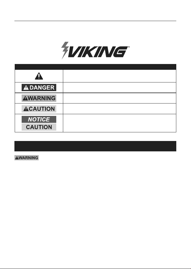
WARNING SYMBOLS AND DEFINITIONS
This is the safety alert symbol. It is used to alert you to
potential personal injury hazards. Obey all safety messages
that follow this symbol to avoid possible injury or death.
Indicates a hazardous situation which, if not avoided,
will result in death or serious injury.
Indicates a hazardous situation which, if not avoided,
could result in death or serious injury.
Indicates a hazardous situation which, if not avoided,
could result in minor or moderate injury.
Addresses practices not related to personal injury.
IMPORTANT SAFETY INSTRUCTIONS
Read all safety warnings and all instructions.
Failure to follow the warnings and instructions may result in electric shock, fire and/or serious injury.
Save all warnings and instructions for future reference.
The warnings and precautions discussed in this manual cannot cover all possible conditions and
situations that may occur. It must be understood by the operator that common sense and caution
are factors which cannot be built into this product, but must be supplied by the operator.
1. Use only according to these instructions.
Improper setup can create hazards.
2. Remove personal metal items such as rings,
necklaces, bracelets, and watches before testing.
3. Wear ANSI-approved safety goggles and
heavy-duty work gloves during setup and use.
4. Be extra cautious to reduce risk of dropping
a metal tool onto battery. It might spark
or short-circuit battery or other electrical
part that may cause explosion.
5. Keep work area clean and well lit.
6. Keep bystanders out of the area
during setup and use.
7. Do not use when tired or when under the
influence of drugs or medication.
8. This product is not a toy. Do not allow
children to play with or near this item.
9. Inspect before every use; do not use
if parts are loose or damaged.
10. Do not expose tester to moisture.
Page 3For technical questions, please call 1-888-866-5797.58792
11. Do not smoke or have open flames near
the battery. Do not operate tester near
flammables such as gasoline, etc.
12. Do not connect the Tester to the battery
while the engine is running. Turn the
engine off before connecting.
13. Do not test a frozen battery.
14. If battery has just been charged, ventilate
the area thoroughly before testing it. Be
careful to avoid creating sparks.
15. Risk of fire, electric shock, or injury - Do not use any
attachment not recommended by the manufacturer.
16. Do not use tester if cord is defective;
take it to a qualified technician when
service or repair is required.
17. Do not disassemble tester or operate if it
has been dropped, received a sharp blow,
or damaged in any way; take it to a qualified
technician when service or repair is required.
18. Have plenty of fresh water and soap nearby in
case battery acid contacts skin, clothing, or eyes.
19. Do not test a damaged battery. Inspect
battery for cracked or broken case or cover.
20. Keep corrosion from battery terminals
from contact with eyes.
21. To reduce risk of explosion, do not connect both
clamps directly to battery at same time. When
making each connection, twist or rock clamp
back and forth to ensure a good connection and
minimize sparks. Do not twist or rock clamp on
battery after second connection has been made.
22. If battery acid contacts skin or clothing,
wash immediately with soap and water. If
acid enters eye, immediately flood eye with
running cold water for at least 10 minutes
and get medical attention immediately.
23. Maintain product labels and nameplates.
These carry important safety information.
If unreadable or missing, contact
Harbor Freight Tools for a replacement.
SAVE THESE INSTRUCTIONS.
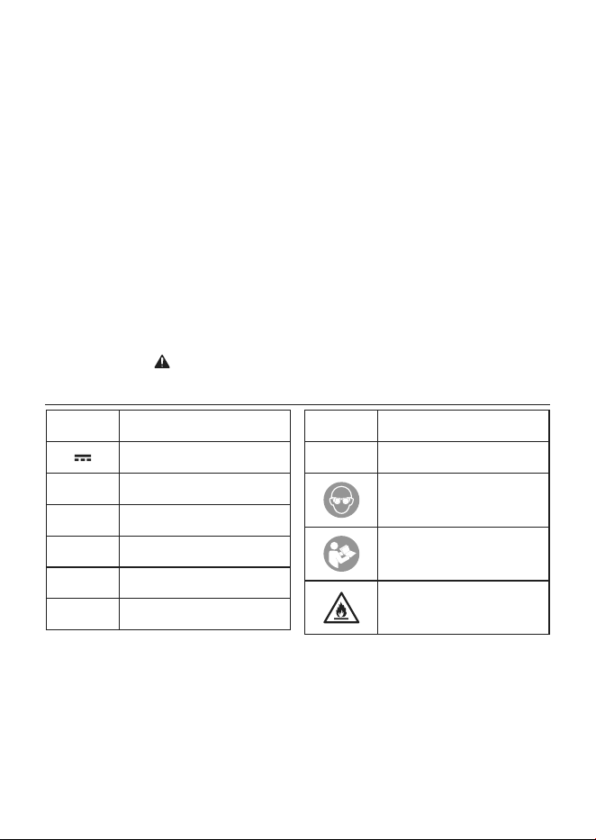
SYMBOLOGY
V
Volts
Direct Current
A
Amperes
CA
Cranking Amps
CCA
Cold Cranking Amps
MCA
Marine Cranking Amps
IR
Internal Resistance
RC
Reserve Capacity
Ah
Ampere-hours
WARNING marking
concerning Risk of Eye Injury.
Wear ANSI-approved
splash-resistant safety goggles.
Read the manual before
set-up and/or use.
WARNING marking
concerning Risk of Fire.
Follow connection procedure.
Page 4 For technical questions, please call 1-888-866-5797. 58792
Specifications
Display LCD
Battery Voltage Application
6V / 12V (Battery Test)
6V / 12V / 24V (System Test)
Tester Voltage Range Capacity 1.24V - 30V
Battery Type Flooded, AGM Flat, AGM Spi, GEL, EFB
Battery CCA Range 40 ~ 2000 CCA
Battery AH Range 5 - 250Ah
Testing Metrics
Battery, Alternator / Charging, Cranking / Starting, Battery
Internal Resistance, Crank Amps, Marine Crank Amps
Test Record Storage 50 records
Printer Paper Thermal Paper, 2-1/4" W x 50′ L (Ø 1-7/16")
Cable / Clamps 10′, 16AWG Cable / Copper Plated Steel Clamps
Power Battery being tested and 9V Battery
Setup - Before Use:
Read the ENTIRE IMPORTANT SAFETY INFORMATION section at the beginning of this
manual including all text under subheadings therein before set up or use of this product.
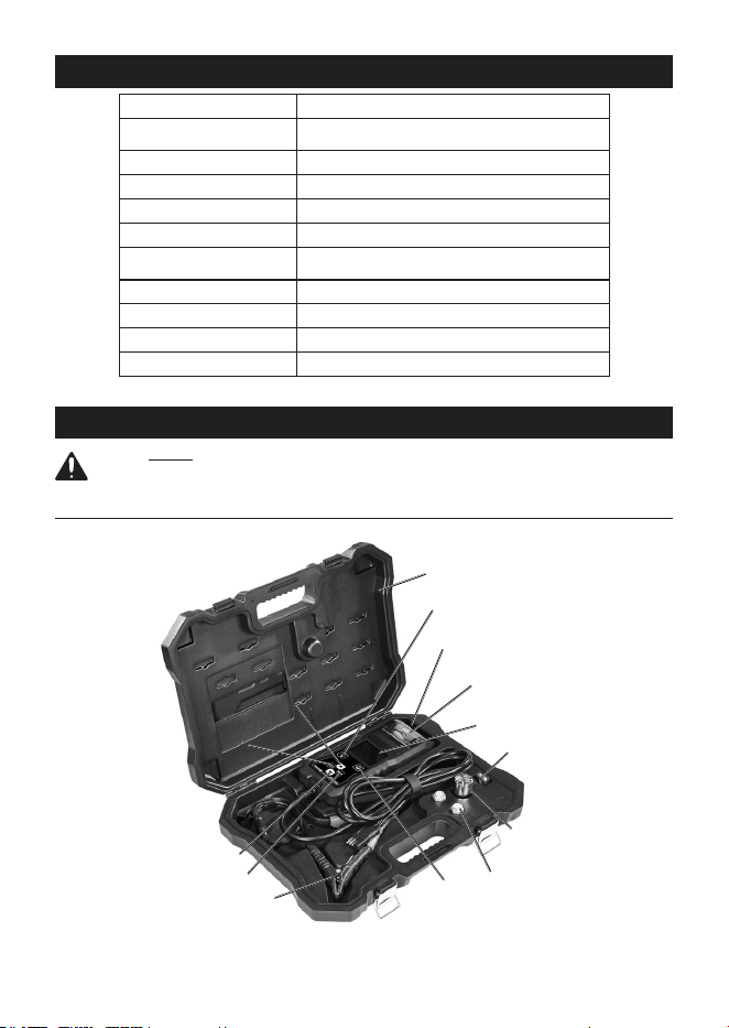
Functions
ClampsClamps
Scroll UpScroll Up
ExitExit
EnterEnter
LED Flashlight LED Flashlight
ON / OFFON / OFF
PrintPrint
LCD DisplayLCD Display
PrinterPrinter
Battery Battery
PostsPosts
Scroll DownScroll Down
Thermal Thermal
Paper RollPaper Roll
9V Battery9V Battery
CaseCase
LED Flashlight LED Flashlight
(front of unit)(front of unit)
Page 5For technical questions, please call 1-888-866-5797.58792
Operating Instructions
Read the ENTIRE IMPORTANT SAFETY INFORMATION section at the beginning of this
manual including all text under subheadings therein before set up or use of this product.
Note: This Tester is powered by the battery
being tested. Install the 9V battery to
power the LED Flashlight and test external
batteries below 6V. Connect clamps to 12V
battery to access report and print.
Note: Suggested operational range -4°F (-20°C)
to 122°F (50°C) ambient air temperature.
1. The battery should be rested 30 minutes
before testing. Vehicle should be turned
off with no accessories operating.
2. Attach clamps securely to the battery terminals,
red to positive (+), black to negative (-).
terminals should be cleaned prior to testing.
Note: If removing battery from vehicle,
disconnect negative (-) terminal first.
3. Non-sealed batteries: Add distilled water in
each battery cell until acid reaches manufacturer
recommended levels. Do not overfill.
4. Test a single 6V or 12V battery only. Do not
connect this Tester to a series of batteries
or an electrical system containing more
than one 6V / 12V / 24V battery. Do not
connect to any other electrical system;
damage to the Tester will result.
5. Be careful not to damage the Tester. Avoid
dropping it or dropping items onto it. Do
not expose to moisture or chemicals.
6. The Tester may be used continuously
without overheating.
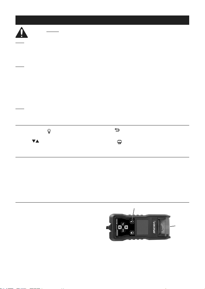
Controls
LED FLASHLIGHT ( )Key: Power LED Flashlight
ON and OFF.
SCROLL ( ) Keys: Select Menu Items. Input data.
EXIT ( ) Key: Return to Main Menu.
ENTER Key: Confirm Menu selection.
PRINT ( ) Key: Print out test results.
Battery Posts
Battery Posts are provided to simplify
connections to side post style batteries.
1. Disconnect negative (-) battery cable
from negative (-) battery terminal.
2. Disconnect positive (+) battery cable
from positive (+) battery terminal.
3. Thread Battery Posts into battery terminals.
4. Connect Tester cable Clamps to
Battery Posts for testing.
5. Remove Battery Posts when finished testing.
LED Flashlight
Digital Tester is equipped with a LED Flashlight for
additional illumination.
Press the LED Flashlight key once to turn the
LED Flashlight ON, and again to turn it OFF.
LED Flashlight LED Flashlight
ON / OFFON / OFF
LED Flashlight LED Flashlight

Page 6 For technical questions, please call 1-888-866-5797. 58792
Tool Setup
Unit must be connected to the battery to be tested.
See Battery Replacement on page 10. Tester will
display the home screen, showing battery status of the
battery being tested. If the battery connection is poor,
“CHECK CONNECT” will be displayed; correct battery
connection. Press EXIT to leave current screen and
return to previous screen without making a selection.
1. Press ENTER to enter Select Function screen.
2. Use SCROLL keys to highlight
Settings; press ENTER.
3. Under Settings, there are four options; use
SCROLL keys to highlight desired option and
press ENTER to select the option to enter
information. Press ENTER to save. Use
SCROLL keys to input data for each option.
a. Screen Contrast - Adjust screen contrast.
b. Tool Information - Hardware/
software version, date and time.
Note: If date and time cannot be saved, connect
to a 12V external battery for a minimum of
2 hours. After 2 hours, reset time and date.
c. Printer - Enter customer information.
d. License - Enter customer license plate number.
Loading Printer Paper:
Note: Unit must be connected to a 12V battery
to test printing after loading printer paper.
1. Open Printer Paper Cover.
2. Set Thermal Paper Roll in chamber,
orientated with the Paper feeding off the
bottom of the roll towards the Cutter.
Note: Printer uses standard thermal paper
available from most office supply stores.
3. Feed the Paper until it begins
to feed past the Cutter.
4. Close the Printer Paper Cover.
5. Connect Unit to 12V battery to
access report and print.
Note: Printer will not work if 12V battery
voltage drops below 7.5V.
Page 7For technical questions, please call 1-888-866-5797.58792
Battery Test
For testing 6V and 12V batteries ONLY.
Suggested operational range 32°F (0°C) to
122°F (50°C) ambient air temperature. Press
EXIT to leave current screen and return to
previous screen without making a selection.
1. Press ENTER to enter Select Function screen.
2. Use SCROLL keys to highlight Battery / Electrical
System Test; press ENTER.
3. Under Select Test, use SCROLL keys to
highlight Battery Test option; press ENTER.
4. Under Select Voltage, use SCROLL keys to
highlight 6V or 12V Battery option; press ENTER.
Note: If voltage is more than 8V / 16V, a VOLTAGE
HIGH message will appear. Causes and Solutions:
a. User accidentally selected wrong battery
voltage - Select correct battery voltage.
b. Battery voltage exceeds upper limit
because tester was connected while
battery was being charged - Stop
charging of battery before testing.
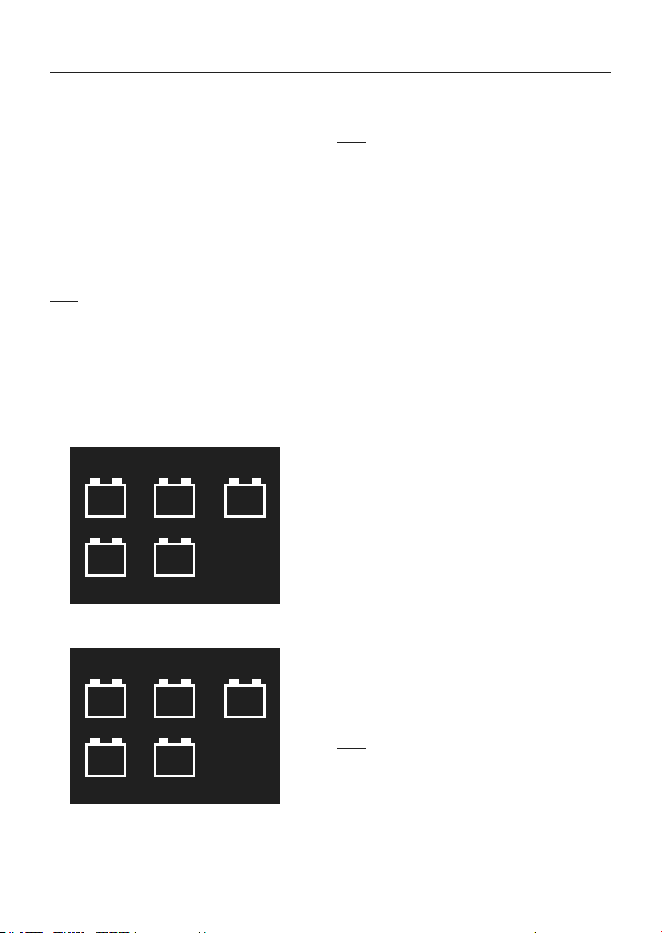
5. Under Select Battery Type, use SCROLL keys
to highlight Battery Type option; press ENTER.
Select Battery Type
AGM
Flat
FLO-
ODED
AGM
Spi
GEL EFB
6. Under Select Battery Rating, use SCROLL keys
to highlight Battery Rating option; press ENTER.
Select Battery Rating
CCA
MCA SAE
AH
CA
7. Under Enter Current Environment, use SCROLL
keys to highlight Temperature option closest to
your ambient temperature; press ENTER.
8. Under Select Capacity, use SCROLL
keys to input Battery Rated CCA, MCA
or CA or AH value; press ENTER.
Note: CCA, SAE, CA, MCA: Minimum step size is 5
when Scrolling.
AH: Hold SCROLL keys to quickly adjust
the value without releasing.
9. Under In-Vehicle Battery Test, use SCROLL keys
to highlight YES or NO option; press ENTER.
a. If YES was entered: If a surface charge is
detected on the battery (battery voltage ≥
6.5V for 6V battery, or ≥ 13V for 12V battery)
a warning message “SURFACE CHARGE!
- Please Turn On The Lights For 10 Sec.”
will appear. Turn on lights for ten seconds
before proceeding. Repeat this step until no
surface charge is detected, and the battery
test is carried out with results displayed.
A surface charge gives an inaccurate
high voltage reading and test result.
b. If NO was entered: Battery test is
carried out with results displayed.
10. Under Test Result, the following is displayed:
• Battery (Bad, Good)
• Battery Type
• State of Health
• State of Charge
• Battery Voltage
• Internal Resistance
• Set Value
• Measured Value
• Temperature Value
• Customer License Number
• Date / Time
11. If desired, press ENTER to save test result or
press PRINT key to print out test results directly.
a. “TEST RECORD SAVED” messaged is
displayed after successful saved test result.
b. After saving test result, press ENTER
to return to main menu.
Note: Tester will not print under following conditions:
• Clamp voltage lower than 7.5V when
connected to external 12V battery.
• Thermal protection plate exceeds
167°F (75°C) - “Printer Temperature Is
Too High” message is displayed.
• Paper too short or missing - “No
Paper” message is displayed.

Page 8 For technical questions, please call 1-888-866-5797. 58792
Electrical System Test
For testing 6V / 12V / 24V systems. Suggested
operational range 32°F (0°C) to 122°F (50°C)
ambient air temperature. Press EXIT to
leave current screen and return to previous
screen without making a selection.
1. Press ENTER to enter Select Function screen.
2. Use SCROLL keys to highlight Battery / Electrical
System Test; press ENTER.
3. Under Select Test, use SCROLL keys to
highlight Electrical System Test option; press
ENTER to proceed to “Starting Test”.
a. Follow prompts on Display to turn off head
lights and accessories, then starting engine.
b. When the change in voltage is detected it will
initiate the “Show Startup Result” message on
the Display.
PASS: Battery is in good condition.
FAIL: Battery needs recharged or replaced.
Note: Tester will automatically detect voltage system.
If external voltage < 7.75V, 6V test will initiate.
If external voltage is 7.75~15.5V, 12V test will initiate.
If external voltage > 15.5V, 24V test will initiate.
4. Press ENTER to proceed to “Charging
Test”. Follow prompts on Display to turn
off head lights and accessories.
a. Press ENTER for next step; Charging Test
results are displayed (FAIL / PASS and Alternator
Idle Voltage).
PASS: Charging system is in good condition.
FAIL: Charging system voltage is low. Check
drive belt for slippage. Check alternator
and battery connection. If drive belts and
connections are in good condition, follow
manufacturer’s suggestion to eliminate
alternator fault.
FAIL- Charging system voltage is high.
Replace alternator assembly or regulator
(older vehicles). Too high charging voltage
will overcharge battery and shorten its life.
b. Press ENTER for next step. Follow prompts on
Display to turn on head lights and accessories,
and rev and hold engine at 2000 RPM for 15
seconds during test. Press ENTER when ready.
c. “Ripple Test Is In Progress” with a countdown
timer will be displayed. At the end of the
Ripple Test, results will be displayed.
d. Press ENTER for next step; Ripple Test results
are displayed (FAIL / PASS and Alternator Load
Voltage).
PASS: Charging system is operating normally.
FAIL: Charging system needs
inspection and repair.
e. Press ENTER for next step. Follow
prompts on Display to turn off engine.
5. Press ENTER to display first screen of Test Results.
6. Press ENTER to save or EXIT to skip
to next screen of Test Results.
7. If desired, press PRINT key to print
out test results directly.
Note: Tester will not print under following conditions:
• Clamp voltage lower than 7.5V when
connected to external 12V battery.
• Thermal protection plate exceeds
167°F (75°C) - “Printer Temperature Is
Too High” message is displayed.
• Paper too short or missing - “No
Paper” message is displayed.
8. Press ENTER to save or EXIT to skip back
to previous screen of Test Results.
9. If Test Results are saved, “TEST RECORD
SAVED” will appear in the Save Result screen.
Press ENTER or EXIT to return to main menu.

Page 9For technical questions, please call 1-888-866-5797.58792
Test Records
Unit must be connected to a 12V battery access report
and print. Press EXIT to leave current screen and
return to previous screen without making a selection.
The tester is capable of storing up to 50 test records.
1. Press ENTER to enter Select Function screen.
2. Use SCROLL keys to highlight
Test Records; press ENTER.
3. Under Test Records, use SCROLL keys
to highlight desired option and press
ENTER. Two options are displayed:
a. Battery Test.
b. Electrical System Test.
4. Under either option from previous step, use
SCROLL keys to highlight desired test record
and press ENTER to view those test results.
To delete:
1. Press EXIT for three seconds to access Deleting
Function screen. Two options are displayed:
a. Delete This Record.
b. Delete ALL Records.
2. Under Deleting Function screen, use SCROLL
keys to highlight desired option; press ENTER;
the Display will offer YES and NO options.
3. Highlight and select the desired option; press
ENTER; “RECORD DELETED” will be displayed.
Page 10 For technical questions, please call 1-888-866-5797. 58792
Maintenance and Servicing
Procedures not specifically explained in this manual must
be performed only by a qualified technician.
Cleaning, Maintenance, and Lubrication
1. Wipe unit with a dry, lint-free cloth. Do
not use solvents or abrasives.
2. Remove battery if not in use for long periods.
3. Store unit in a dry location.
4. Other than the battery, there are no replaceable
parts on this unit. Repairs should be
done by a qualified technician.
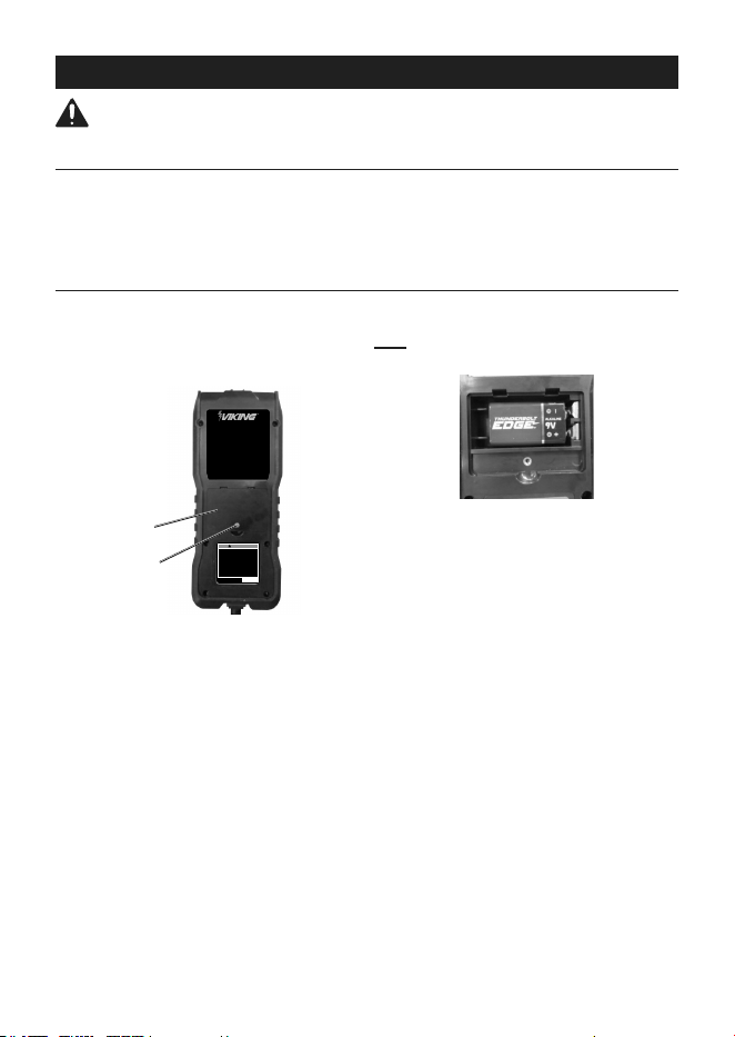
Battery Replacement
If the Tester display reads “POWER LOW”,
the battery should be replaced.
1. Turn the unit over.
2. Remove screw and back cover.
DIGITAL BATTERY & SYSTEM
TESTER WITH PRINTER
Tests Battery, Alternator / Charging,
Cranking / Starting, Battery Internal
Resistance, Crank Amps, & Marine
Crank Amps
OPERATION GUIDE:
1. Follow on-screen instruction to
operate.
2. Connect to test battery with 9V
battery installed to print.
23c
WARNING
To prevent serious injury:
1. Wear ANSI-approved safety
goggles during use.
2. Remove metal jewelry
and watches before
working near batteries.
3. Use on single 6V or 12V
batteries only.
4. Read manual before
set up and/or use.
UPC 193175446701
Serial:
58792
23c
Battery
Cover
Screw
3. Pull battery out of unit and replace with the same
(9V battery). Confirm battery orientation is correct.
Note: Press LED Flashlight button to
confirm LED Flashlight is operable.
4. Replace cover and retighten screw.

Page 11For technical questions, please call 1-888-866-5797.58792
Note: This equipment has been tested and found to comply with the limits for a Class B digital device, pursuant to
part 15 of the FCC Rules. These limits are designed to provide reasonable protection against harmful interference
in a residential installation. This equipment generates, uses and can radiate radio frequency energy and, if not
installed and used in accordance with the instructions, may cause harmful interference to radio communications.
However, there is no guarantee that interference will not occur in a particular installation. If this equipment does
cause harmful interference to radio or television reception, which can be determined by turning the equipment off
and on, the user is encouraged to try to correct the interference by one or more of the following measures:
—Reorient or relocate the receiving antenna.
—Increase the separation between the equipment and receiver.
—Connect the equipment into an outlet on a circuit different from that to which the receiver is connected.
—Consult the dealer or an experienced radio/TV technician for help.
Note: Replacement parts are not available. Reference UPC 193175446701
Do not open housing; no user-serviceable parts inside.
Record Product’s Serial Number Here:
Note: If product has no serial number, record month and year of purchase instead.

Limited 90 Day Warranty
Harbor Freight Tools Co. makes every effort to assure that its products meet high quality and durability
standards, and warrants to the original purchaser that this product is free from defects in materials
and workmanship for the period of 90 days from the date of purchase. This warranty does not apply to
damage due directly or indirectly, to misuse, abuse, negligence or accidents, repairs or alterations outside
our facilities, criminal activity, improper installation, normal wear and tear, or to lack of maintenance.
We shall in no event be liable for death, injuries to persons or property, or for incidental, contingent,
special or consequential damages arising from the use of our product. Some states do not allow the
exclusion or limitation of incidental or consequential damages, so the above limitation of exclusion
may not apply to you. THIS WARRANTY IS EXPRESSLY IN LIEU OF ALL OTHER WARRANTIES,
EXPRESS OR IMPLIED, INCLUDING THE WARRANTIES OF MERCHANTABILITY AND FITNESS.
To take advantage of this warranty, the product or part must be returned to us with transportation charges
prepaid. Proof of purchase date and an explanation of the complaint must accompany the merchandise.
If our inspection verifies the defect, we will either repair or replace the product at our election or we may
elect to refund the purchase price if we cannot readily and quickly provide you with a replacement. We will
return repaired products at our expense, but if we determine there is no defect, or that the defect resulted
from causes not within the scope of our warranty, then you must bear the cost of returning the product.
This warranty gives you specific legal rights and you may also have other rights which vary from state to state.
26677 Agoura Road • Calabasas, CA 91302 • 1-888-866-5797