© 2026 Ad Hoc Electronics | Page 1
USER MANUAL
E9T-210U
Kinetic Switch Module
902 MHz Frequency
January 2026
Published by:
Ad Hoc Electronics
Lindon, Utah, United States
www.adhocelectronics.com
© Ad Hoc Electronics All Rights Reserved
Important!
This information describes the type of component and shall not be considered as assured characteristics.

© 2026 Ad Hoc Electronics | Page 2
No responsibility is assumed for possible omissions or inaccuracies. Circuitry and specifications are
subject to change without notice. For the latest product specifications, refer to the Ad Hoc Electronics
website: http://www.adhocelectronics.com.
As far as patents or other rights of third parties are concerned, liability is only assumed for devices, not for
the described applications, processes and circuits.
Ad Hoc Electronics does not assume responsibility for use of devices described and limits its liability to
the replacement of devices determined to be defective due to workmanship. Devices or systems
containing RF components must meet the essential requirements of the local legal authorities.

© 2026 Ad Hoc Electronics | Page 3

© 2026 Ad Hoc Electronics | Page 4
1. GENERAL DESCRIPTION
The E9T-210U pushbutton transmitter from Ad Hoc Electronics is a drop-in replacement for the
EnOcean PTM 210U module. This module enables the implementation of wireless switches and
remote controls without batteries. The E9T-210U is self-powered (no batteries) and therefore
maintenance-free. The power is provided by a built-in electro-dynamic power generator.
The main application is wireless switches in smart buildings. Products based on E9T-210U
modules can also be used in hermetically sealed systems or in remote (not easily accessible)
locations.
The E9T-210U operates at 902.875 MHz and is compliant with FCC and Industry Canada
regulatory requirements for the North American market.
1.1 Product Specifications
Parameter Specification
Model E9T-210U
Frequency 902.875 MHz (FSK)
Power Supply Electro-dynamic power generator
Antenna Integrated PCB antenna
Data Rate 125 kbps
Conducted Output Power +10 dBm
Transmission Range Typical 300 m free field, typical 30 m
indoor
Channels Two channels with two pushbuttons per
channel
Device Identifier Individual 32-bit ID (factory programmed)
Redundant Sub-telegrams 3 per transmission
Radio Standard ERP2 based on ISO/IEC 14543-3-11
Equipment Profile F6-02-04, F6-04-02
1.2 Mechanical Interface
Parameter Specification
Device Dimensions 40.0 x 40.0 x 11.2 mm
Device Weight 20 g ± 1 g

© 2026 Ad Hoc Electronics | Page 5
Energy Bow Travel 1.8 mm
Operating Force Typical 9 N at room temperature
Restoring Force Typical 0.7 N to 4 N (min 0.5 N required)
Number of Operations Typical 100,000 actuations at 25°C
Cover Material Hostaform (POM)
Energy Bow Material PBT (50% GV)
1.3 Environmental Conditions
Parameter Specification
Operating Temperature -25°C to +65°C
Storage Temperature -25°C to +65°C
Humidity 0% to 95% r.h.

© 2026 Ad Hoc Electronics | Page 6
2. FUNCTIONAL DESCRIPTION
The E9T-210U contains an electro-dynamic energy transducer which is actuated by a bow. This
bow is pushed by an appropriate push button, switch rocker or a similar construction mounted
onto the device. An internal spring will release the energy bow as soon as it is not pushed down
anymore.
When the energy bow is pushed down, electrical energy is harvested and a radio telegram is
transmitted. Releasing the energy bow similarly generates energy which is used to transmit
another radio telegram.
2.1 Contact Nipples Assignment
The E9T-210U provides four contact nipples. They are grouped into two channels (Channel A
and Channel B) each containing two contact nipples (State O and State I). The nipples are
therefore referred to as: AO, AI, BO and BI.
The state of all four contact nipples is transmitted together with a unique device identification
whenever the energy bow is pressed or released as a part of an EnOcean radio telegram.
2.2 EnOcean Equipment Profiles
The EnOcean Equipment Profile (EEP) defines how the data within an EnOcean telegram is
encoded. The E9T-210U supports the following ERP2 profiles:
•
F6-02-04 - Rocker switch, 2 rockers
•
F6-04-02 - Key card switch
Note: There is no EEP Teach-in message sent by the E9T-210U. The receiver must be
configured to recognize these profile types.

© 2026 Ad Hoc Electronics | Page 7
3. PRODUCT LABEL SPECIFICATIONS
The product label is a critical component for product identification, traceability, and
regulatory compliance. This section provides comprehensive specifications for the label
design, content, and QR code structure.
3.1 Label Layout and Content
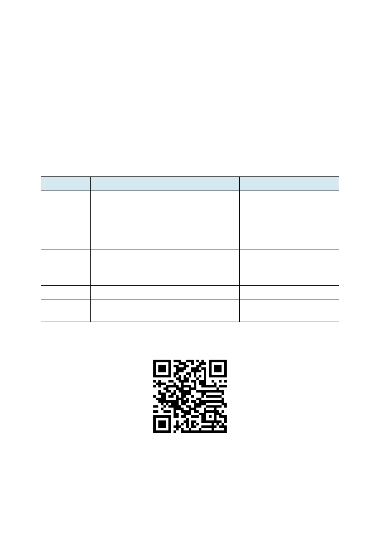
The product label must contain the following information:
Field Content / Example
Model E9T-210U
Frequency 902.875 MHz
Company Name Ad Hoc Electronics
EnOcean ID Unique 32-bit ID in hexadecimal format (8 hex digits)
Example: 0x00500100
FCC ID FCC: [Your FCC ID]
IC ID IC: [Your IC ID]
Production Date Week / Year format Example: 03 / 26 (3rd week of 2026)
QR Code Machine-readable code containing product tracking
information (See Section 3.2 for detailed QR code
structure)
© 2026 Ad Hoc Electronics | Page 8
3.2 QR Code Structure
The QR code is CRITICAL for product traceability and must encode information
according to the EnOcean Alliance Labeling standard (ANSI MH10.8.2 format). The QR
code contains a text string with multiple information containers separated by the "+"
character.
3.2.1 QR Code Example
Example QR code string:
30S00500100+1P000800000023+30PE9T-210U+2PA01
3.2.2 QR Code Field Definitions
Identifier Description Length Example Value
30S EnOcean Radio ID
(32-bit format)
11 characters (3 + 8
hex digits)
30S00500100
+ Field Separator 1 character
+
1P EnOcean Alliance
Product ID
14 characters (2 +
12 hex digits)
1P000800000023
+ Field Separator 1 character
+
30P Product Model
Number
13 characters (3 +
10 alphanumeric)
30PE9T-210U
+ Field Separator 1 character
+
2P Step Code and
Revision
6 characters (2 + 4
alphanumeric)
2PA01
Example QR Code:
Encoding: 30S00500100+1P000800000023+30PE9T-210U+2PA01
3.2.3 Field-by-Field Requirements

© 2026 Ad Hoc Electronics | Page 9
30S - EnOcean Radio ID
•
Format: 32-bit hexadecimal ID (8 hex digits)
•
This must match the unique EnOcean ID programmed into the module
•
Example: 00500100 represents ID 0x00500100
•
Total length: 11 characters including identifier (30S)
1P - EnOcean Alliance Product ID
•
Format: Manufacturer ID (4 hex digits) + Product ID (8 hex digits)
•
Manufacturer ID: 0008 (assigned to Ad Hoc Electronics by EnOcean Alliance)
•
Product ID: 00000023 (assigned internally by Ad Hoc Electronics for E9T-210U)
•
Total length: 14 characters including identifier (1P)
30P - Product Model Number
•
Format: Up to 10 alphanumeric characters
•
Value: E9T-210U (product model designation)
•
Total length: 13 characters including identifier (30P)
2P - Step Code and Revision
•
Format: 4 alphanumeric characters
•
This identifies the hardware revision and step code of the product
•
Example: A01 represents Step Code A, Revision 01
•
Total length: 6 characters including identifier (2P)

© 2026 Ad Hoc Electronics | Page 10
3.2.4 Complete QR Code String Format
The complete QR code string follows this structure:
30S[8-digit-hex-ID]+1P000800000023+30PE9T-210U+2P[4-char-step]
Total approximate length: 50 characters
CRITICAL NOTES:
•
The EnOcean Radio ID (30S field) MUST exactly match the ID programmed into the
module's firmware
•
The Product ID (1P field) must use the assigned value 000800000023
•
All hexadecimal values should use uppercase letters
•
Field separators (+) are mandatory between fields
•
QR code should use Error Correction Level M (15% error correction)

© 2026 Ad Hoc Electronics | Page 11
4. RADIO COMMUNICATION
The E9T-210U transmits radio telegrams based on the EnOcean Radio Protocol 2 (ERP2)
standard, which is based on ISO/IEC 14543-3-11. This protocol is optimized for the North
American 902 MHz frequency band.
4.1 ERP2 Communication
The E9T-210U uses the standard ERP2 frame structure with the following key parameters:
•
ADDRESS CONTROL: Originator-ID 32 bit; no Destination-ID
•
EXT. HEADER: No extended header
•
TELEGRAM TYPE: RPS telegram (0xF6)
4.2 Redundant Transmission
To increase communication reliability, each data transmission is repeated 3 times as redundant
sub-telegrams with random timing offsets. The redundant sub-telegrams are 100% identical.
Therefore, it is sufficient for the receiver to successfully receive at least one sub-telegram.

© 2026 Ad Hoc Electronics | Page 12
5. APPLICATION INFORMATION
5.1 Typical Applications
E9T-210U modules are commonly used in the following areas:
•
Building installation - wall-mounted wireless switches
•
Industrial automation - wireless control panels
•
Consumer electronics - handheld remote controls
Key products include wall-mounted switches and handheld remote controls supporting up to two
rockers or up to four pushbuttons.
5.2 Construction of Switch Rockers
Polycarbonate is recommended as rocker material since it is both buckling resistant and wear-
proof. It is also recommended to apply Teflon varnish in the areas of actuation.
IMPORTANT DESIGN CONSIDERATIONS:
•
Use non-conductive material for rockers to ensure best transmission range. Avoid
metallic materials or plastics with conducting ingredients such as graphite.
•
If the rocker is not mounted on the rotation axis, consider tolerances. The measure from
support plane to top of the energy bow is 7.70 mm +/- 0.3 mm.
•
The movement of the energy bow must not be limited by mounted rockers.
•
Catwalks of the switch rocker must not exert continuous forces on contact nipples.
5.3 Device Mounting
CRITICAL MOUNTING REQUIREMENTS:
•
It is recommended NOT to mount the device directly onto metal surfaces or into metal
frames since this can lead to significant loss of transmission range.
•
The E9T-210U is powered by an electromagnetic generator. For proper function,
magnets or ferromagnetic materials are not permitted within a keep-out zone of 60mm
around the center of the module.
5.4 Transmission Range
The transmission range depends on several factors:
•
Type and location of antennas
•
Type of terrain and degree of obstruction
•
Sources of interference
•
Dead spots caused by signal reflections
Expected transmission ranges (approximate):
•
Line-of-sight connections: Typically 30 m in corridors, up to 100 m in halls
•
Plasterboard walls / dry wood: Typically 30 m range, through max. 5 walls
•
Ferro concrete walls / ceilings: Typically 10 m range, through max. 1 ceiling
•
Fire-safety walls, elevator shafts, staircases should be considered as shielded

© 2026 Ad Hoc Electronics | Page 13
NOTE: Range tests should always be performed to determine the reliably achievable range
under actual installation conditions.

© 2026 Ad Hoc Electronics | Page 14
6. REGULATORY INFORMATION
6.1 FCC Compliance
This device complies with part 15 of the FCC rules. Operation is subject to the following two
conditions:
•
This device may not cause harmful interference, and
•
This device must accept any interference received, including interference that may
cause undesired operation.
IMPORTANT: Any changes or modifications not expressly approved by Ad Hoc
Electronics could void the user's authority to operate this equipment.
6.2 Industry Canada Compliance
This device complies with Industry Canada ICES-003. Operation is subject to the following two
conditions:
•
This device may not cause harmful interference, and
•
This device must accept any interference received, including interference that may
cause undesired operation.
Le présent appareil est conforme aux CNR d'Industrie Canada applicables aux appareils radio
exempts de licence. L'exploitation est autorisée aux deux conditions suivantes: (1) l'appareil ne
doit pas produire de brouillage, et (2) l'utilisateur de l'appareil doit accepter tout brouillage
radioélectrique subi, même si le brouillage est susceptible d'en compromettre le fonctionnement.
6.3 End Product Requirements
The final product including the E9T-210U module must meet all necessary application-specific
requirements including:
•
FCC and IC compliance for the complete system
•
Product safety standards compliance
•
RoHS compliance for frame and rockers
•
Proper product labeling and documentation

© 2026 Ad Hoc Electronics | Page 15
7. PRODUCT SAFETY INSTRUCTIONS
E9T-210U modules are not end-customer sold final products. Final products (e.g., switches)
which include E9T-210U modules are to be prepared by partners.
7.1 Intended Use
• Switch products are intended for indoor usage in closed dry rooms.
•
The product must not be used in any relation with equipment that supports, directly or
indirectly, human/animal health or life or with applications that can result in danger for
people, animals or real value.
•
The product is not suitable for use in mechanically or environmentally challenging
environments including (but not limited to) environments with heavy vibrations,
mechanical shocks, very high humidity, very dusty or explosive atmospheres.
•
The installation and assembly of electrical equipment may only be performed by a skilled
electrician.
7.2 Basic Safety Instructions
• Risk of suffocation! Do not leave the packaging material lying around. Children could
swallow the small parts and choke on them.
•
Install and operate product according to user manual and do not modify the product.
•
The product should not be exposed to rapid temperature changes shortly before or
during operation; condensation of moisture has to be avoided.
•
Wrong cleaning may damage the product; we suggest cleaning with soft and damp
tissue.
•
Do not disassemble!

© 2026 Ad Hoc Electronics | Page 16
8. DISPOSAL AND ENVIRONMENTAL INFORMATION
Components of the devices are considered and should be disposed of as hazardous waste.
Local government regulations are to be observed.
PACKING:
Please use the recycling operators known to you. By agreement we will take packing material
back if it is sorted. You must bear the costs of transport. For packing material that is returned to
us unsorted or that we are not obliged to accept, we shall have to invoice you for any costs
incurred.

© 2026 Ad Hoc Electronics | Page 17
9. CONTACT INFORMATION
Ad Hoc Electronics
Lindon, Utah
United States
Website: www.adhocelectronics.com
Email: [email protected]
For technical support, product specifications, or additional documentation, please visit our
website or contact us via email.
FCC Warning
This device complies with part 15 of the FCC Rules. Operation is subject to the
following two conditions: (1) This device may not cause harmful interference, and (2)
this device must accept any interference received, including interference that may
cause undesired operation.
Note: This equipment has been tested and found to comply with the limits for a Class B
digital device, pursuant to part 15 of the FCC Rules. These limits are designed to
provide reasonable protection against harmful interference in a residential installation.
This equipment generates, uses and can radiate radio frequency energy and, if not
installed and used in accordance with the instructions, may cause harmful interference
to radio communications. However, there is no guarantee that interference will not occur
in a particular installation. If this equipment does cause harmful interference to radio or
television reception, which can be determined by turning the equipment off and on, the
user is encouraged to try to correct the interference by one or more of the following
measures:
—Reorient or relocate the receiving antenna.
—Increase the separation between the equipment and receiver.
—Connect the equipment into an outlet on a circuit different from that to which the
receiver is connected.
—Consult the dealer or an experienced radio/TV technician for help.
Note: The Grantee is not responsible for any changes or modifications not expressly
approved by the party responsible for compliance. such modifications could void the
user's authority to operate the equipment.
The device has been evaluated to meet general RF exposure requirement. The device
can be used in portable exposure condition without restriction.
--- END OF DOCUMENT ---