100330658 2000539909C
INSTALLATION MUST BE PERFORMED BY QUALIFIED SERVICE PROFESSIONALS ONLY.
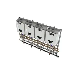
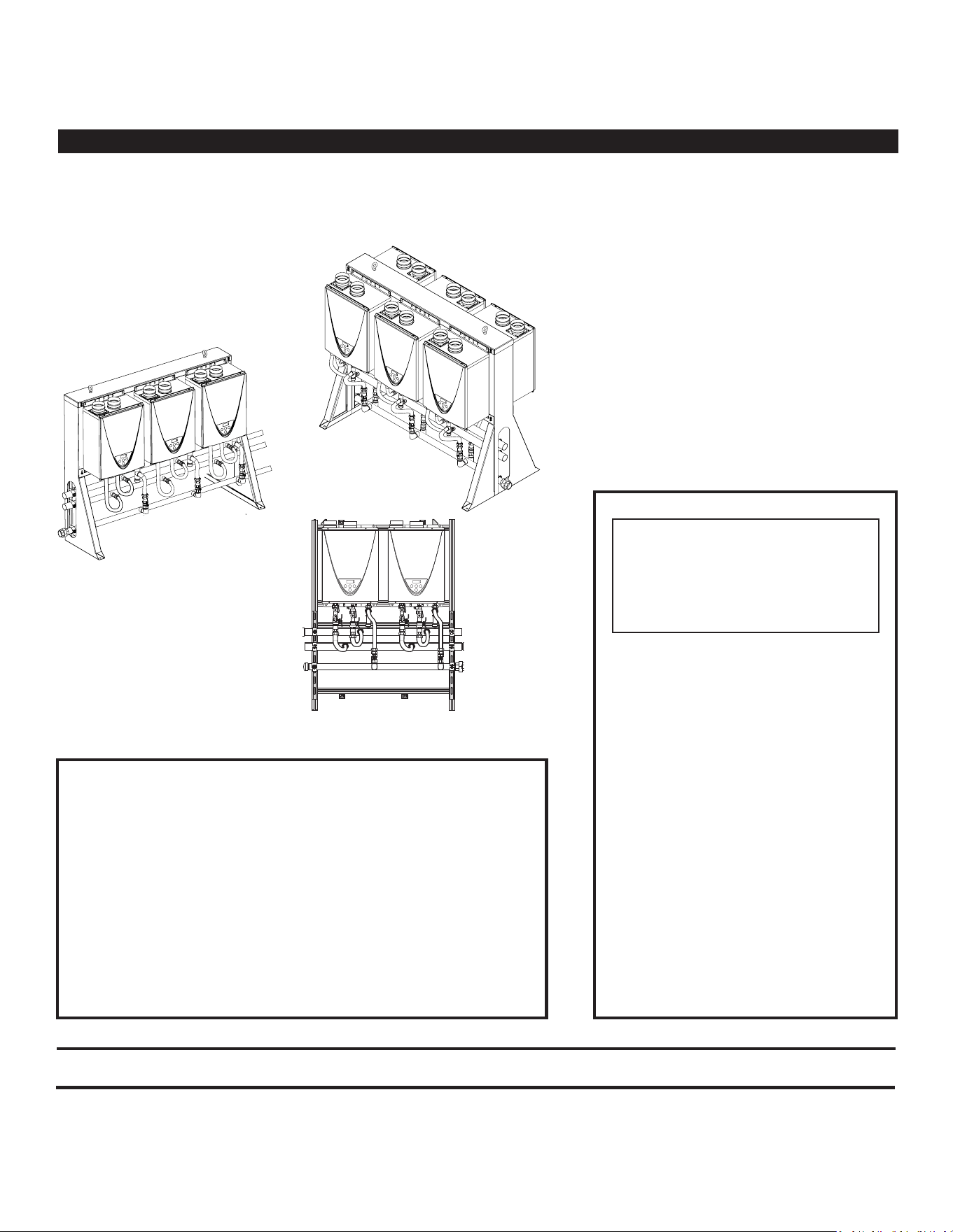
ON-DEMAND RACK SYSTEM
INSTALLATION MANUAL
Do not store or use gasoline or other
ammable vapors and liquids in the
vicinity of this or any other appliance.
WHAT TO DO IF YOU SMELL GAS
• Do not try to light any appliance.
• Do not touch any electrical switch;
do not use any phone in your
building.
• Immediately call your gas supplier
from a neighbor’s phone. Follow the
gas supplier’s instrucons.
• If you cannot reach your gas
supplier, call the re department.
Installaon and service must be
performed by a qualied installer,
service agency or the gas supplier.
WARNING: If the informaon in
these instrucons is not followed
exactly, a re or explosion may
result causing property damage,
personal injury or death.
FREE STANDING
(BACK-TO-BACK)
WALL MOUNT
FREE STANDING
(IN-LINE)
ADDITIONAL INFORMATION IS PROVIDED
IN THE WATER HEATER’S INSTALLATION
MANUAL AND OWNER’S GUIDE. A COPY
IS PROVIDED WITH EACH WATER HEATER
IN THE ASSEMBLY.
Page
Table of Contents Page
Important Safety Informaon .............................................................2
Geng Started ...................................................................................3
Installaon .......................................................................................... 4
Maintenance ....................................................................................10
Specicaons: Wall Mount (42” Frame Width) ................................12
Specicaons: Wall Mount (62.81” Frame Width) ..........................14
Specicaons: Free Standing (41.54” Frame Width) ........................16
Specicaons: Free Standing (62.29” Frame Width) ........................18
Replacement Parts ...........................................................................20
PRINTED 0420
2 • On-Demand Rack System
SAFETY
IMPORTANT SAFETY INFORMATION
WARNING! If the informaon in these instrucons is not followed exactly, a re or explosion may result causing property
damage, personal injury or death. Do not store or use gasoline or other ammable vapors and liquids in the vicinity of this or any
other appliance.
An odorant is added by the gas supplier to the gas used by this water heater. This odorant may fade over an extended period of
me. Do not depend upon this odorant as an indicaon of leaking gas. We recommend installing a fuel gas and carbon monoxide
detector.
Installaon includes the connecon of gas lines, water lines, valves and electricity. Knowledge of applicable naonal, state, and
local codes is necessary. Therefore, installaon must be performed only by qualied service professionals.
Read and follow all instrucons, cauons, and warnings in the water heaters’ Installaon Manuals/Owner’s Guides.
Read and follow all safety messages and instrucons in this manual.
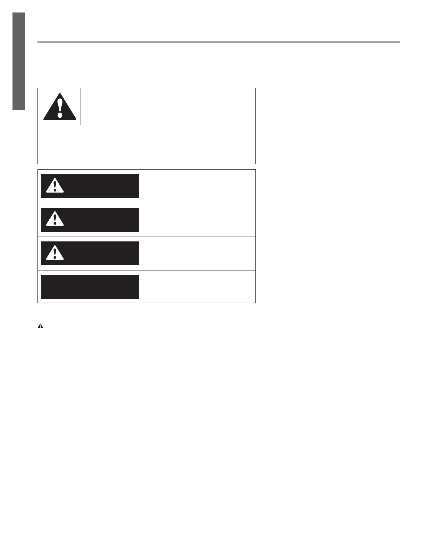
This is the safety alert symbol. It is used to alert you to
potenal physical injury hazards. Obey all safety mes-
sages that follow this symbol to avoid possible property
damage, serious injury or death. Do not remove any
permanent instrucons, labels, or the data plate from either the outside of
the water heater or on the inside of the access panels. Keep this manual
near the water heater.
DANGER
DANGER indicates hazardous situa-
on that, if not avoided, will result
in death or serious injury.
WARNING
WARNING indicates a hazardous
situaon that, if not avoided, could
result in death or serious injury.
CAUTION
CAUTION indicates a hazardous
situaon that, if not avoided, could
result in minor or moderate injury.
NOTICE
NOTICE indicates pracces not
related to physical injury.

On-Demand Rack System • 3
GETTING STARTED
GETTING STARTED
WARNING
Follow all local codes during
installation. In the absence of local
codes, follow the National Fuel Gas
Code, ANSI Z223.1/NFPA 54 (current
edition) in the USA, or in Canada,
follow CAN/CSA B149.1, Natural Gas
and Propane Installation Code (current
edition). Failure to do so may cause
death, personal injury, or property
damage.
Product Registration
The rack system itself does not require
registration. However, each water
heater within the system should be
registered. To do so, fill out and
return the registration card for each
water heater. (Each water heater is
provided with its own manual and
registration card.) Alternatively, you
may register through the website
listed on the registration card.
General Information
The On-Demand Rack System includes
both wall-mounted and free standing
configurations, and several options are
available within each type. Refer to
the Specifications section.
For questions regarding general
operation, refer to the water heaters’
manuals.
Venting
Venting components are not supplied
with the rack system and must be
obtained separately. For venting
instructions, refer to the water
heaters’ installation manuals/owner’s
guides.
Installation
Requirements
• Observe the water heaters’
installaon requirements as outlined
in their installaon manual.
• Installaon and service must be
performed by a qualied service
professional, such as a licensed
plumber or gas er. Otherwise, the
warranty will be void.
• The installer is responsible for the
correct installaon of the water
heater and for compliance with all
code requirements.
• Place the water heaters in a locaon
that provides easy access for service
and maintenance.
• Do not Install the system in a pit or
locaon where gas and water can
accumulate.
• Do not allow the vent terminals to
point toward any operang window,
door, or opening into a building.
• Do not install the system next to any
source of airborne debris that can
cause debris to be trapped inside the
combuson chambers (unless the
system is direct vented).
• The power supply must be 120
VAC (60 Hz) and must be properly
grounded.
Indoor Models
• Do not install indoor models
outdoors.
• Due to safety concerns, ac
installaons are not recommended.
If you install the system in an ac:
ᴏ
Make sure the water heaters will
have enough combuson air and
proper venlaon. Refer to the
installaon manual for the water
heaters.
ᴏ
Keep the area around the
water heaters clean. When dust
collects on the ame sensors,
the water heaters will shut down
and produce an error code.
ᴏ
A drain pan, or other means
of protecon against water
damage, is required to be
installed under the water heaters
in case of leaks.
• It is recommended to direct vent the
water heaters.
• Ensure that the surrounding areas
are protected from potenal water
damage (i.e., condensate discharge,
etc.). In the absence of local codes
and regulaons, it is recommended
that condensate be disposed of in a
standard drain.
Outdoor Models
• Do not install outdoor models
indoors.
• Outdoor models must be installed
only in an area with a mild,
temperate climate. Also, refer to
the water heaters’ manual for freeze
protecon informaon.
• Ensure that the installaon is in an
open, unroofed area with minimum
clearances observed.
• Ensure that the surrounding areas
are protected from potenal water
damage (i.e., condensate discharge,
etc.). In the absence of local codes
and regulaons, it is recommended
that condensate be disposed of in a
standard drain.
4 • On-Demand Rack System
INSTALLATION
INSTALLATION
1
Install the
Rack(s)
When installing the rack(s), you
must comply with the water heaters’
installation requirements. Refer to
the Installation Manual and Owner’s
Guide.
See also Installation Requirements on
page 7.
• WARNING! The oor or wall
must be able to support the rack
system in a secure and safe
manner. Follow local and state
code requirements. Failure to do
so can lead to loss of life, personal
injury, and/or property damage.
ᴏ
Areas prone to earthquakes
may have addional code
requirements. Prior to
installaon, contact the local
authority having jurisdicon
over installaon requirements.
ᴏ
Ensure that you use oor/
wall anchors with an adequate
weight rang.
• This rack system and its water
heaters must be installed according
to all local and state codes or, in the
absence of local and state codes,
the “Naonal Fuel Gas Code”, ANSI
Z223.1(NFPA 54)-current edion.
• Install the rack(s) in a locaon
where the proper amount of
combusble air will be available to
it at all mes without obstrucons.
(Refer to the water heaters’
Installaon Manual and Owner’s
Guide.)
• The system must be installed in a
locaon that provides easy access
for service and maintenance.
• Outdoor Systems:
Ensure that the installaon is in an
open, unroofed area with minimum
clearances observed.
Wall Mounted Rack
A. Before you begin, read all warnings
and bullet points at the beginning of
this secon.
NOTICE: Determine your
installaon locaon, then conrm
that the clearance requirements
are met. (Refer to the water heater
manual and applicable code.)
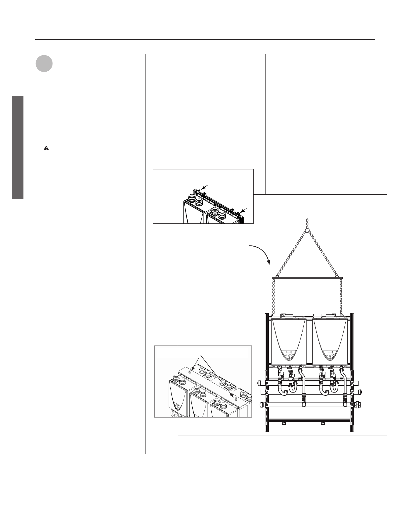
NOTICE: Wall mount racks are
shipped with liing brackets in
place. See Figure 1. These lifting
brackets are actually wall mount
brackets that have been rotated
90 degrees. They will allow you to
hoist the rack without the use of
straps. Use a spreader lifting bar
as shown in Figure 2 to ensure that
the lifting force is vertical.
B. Aach the rack to the wall, and
ensure that it is secure. The rack
must be secured at each mounng
bracket. NOTE: The mounng
brackets can be moved along the
channel to line up with the framing.
INSTALLATION
Figure 1: Lifting Brackets
Figure 2: Spreader Lifting Bar
Figure 3: Lifting Eyebolts
On-Demand Rack System • 5
INSTALLATION
INSTALLATION
ᴏ
The clearance hole in each
mounng bracket is 1/2-inch in
diameter. Fasteners must be
appropriate for the weight of the
rack and the material to which
it is being mounted. When
in doubt, consult a licensed
structural engineer.
ᴏ
Use a leveling tool to make sure
that the assembly is level. To
operate properly, the assembly
must be level and the water
heaters must be in an upright
posion (as shown in Figure 4,
page 6).
Free Standing Rack
A. Before you begin, read all warnings
and bullet points at the beginning of
this secon.
B. Place the rack and ensure that it
is level. (The free-standing rack is
equipped with liing eyebolts. See
Figure 3.)
NOTICE: You may need to use straps
to ensure that the liing force is
vercal.
C. Verify that the clearance
requirements are met. (Refer to the
water heater manual and applicable
code.)
D. Anchor the rack to the oor at each
leg. It must be secure and must not
allow movement.
NOTICE: The clearance hole in
each leg is 1/2-inch in diameter.
Fasteners must be appropriate for
the material to which the rack is
being mounted. When in doubt,
consult a licensed structural
engineer.
Mul-Unit Controller
If your installation includes more than
four water heaters, you will need to
install a multi-unit controller. See the
configuration section on page 7 for
more information.
Piping Requirements
• Piping for up to six water heaters:
A rack system is designed with piping
to handle up to six water heaters. If
the job requires four to six heaters
in more than one format, then you
can use two racks that provide the
sum total of the required number of
heaters. For example, if you needed
ve heaters total, you could install a
rack with three heaters and another
with two heaters. The water lines
and gas line can be joined on site.
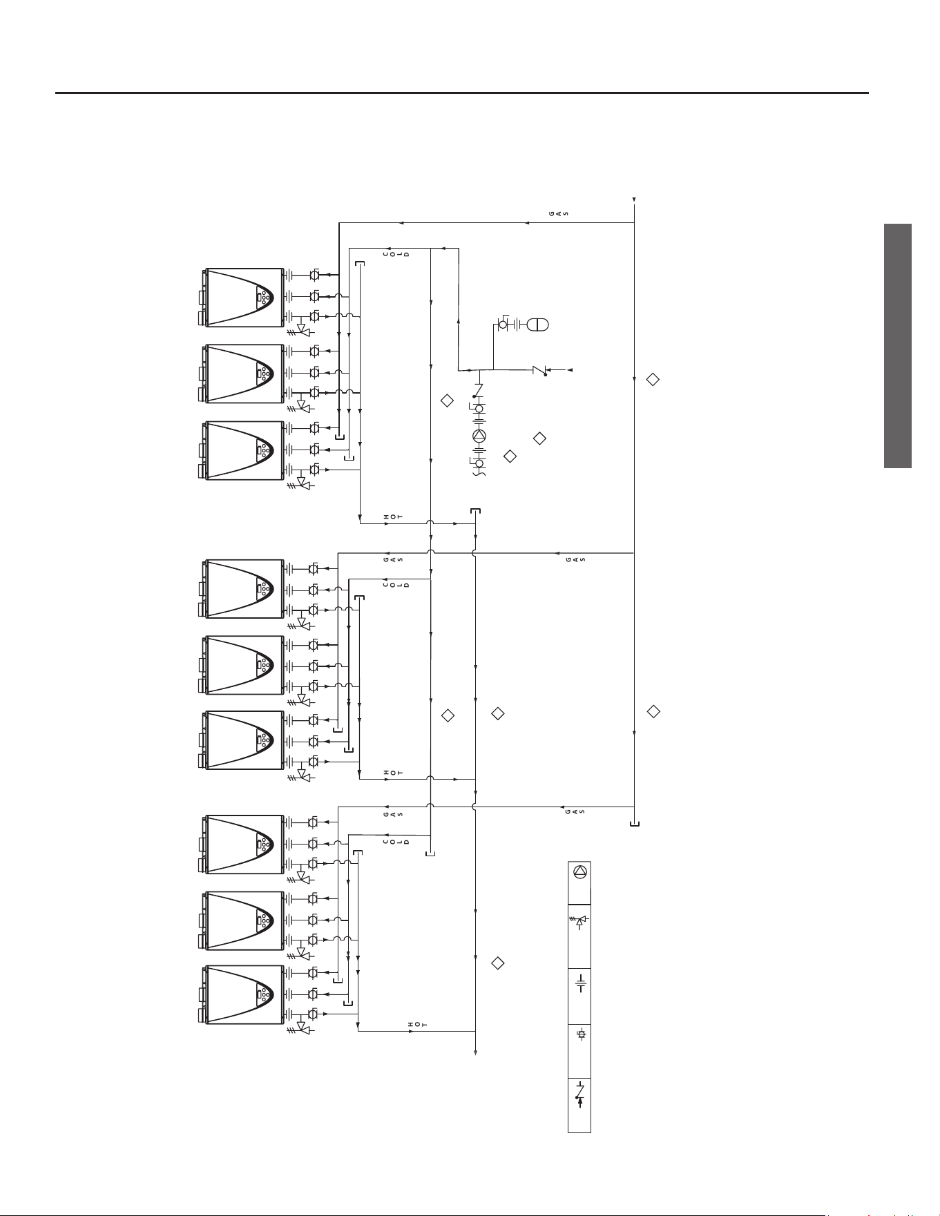
• Piping for six or more water
heaters: If the job requires mulple
racks that total more than six water
heaters, refer to the piping diagram
on page 9. Mulple rack systems
require a reverse return setup to
balance ows across the system.
Size the hot and cold headers that
supply the rack systems so that
they can accommodate the water
volume that is required. (These
headers will be larger than the rack
system piping.) The gas supply
header should be sized to supply the
maximum input of the total number
of water heaters. Follow proper
trade pracces and refer to ANSI
Z223.1/NFPA 54 (current edion) for
proper sizing.
2
Install the Water
Supply
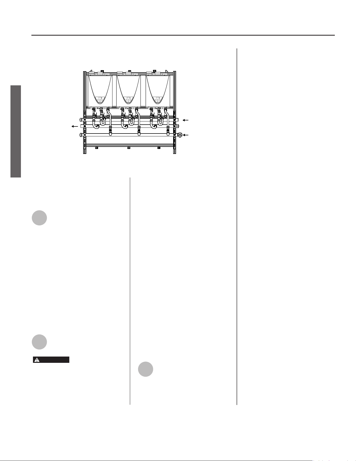
Once flow direction has been determined
and the inlet and outlet sides are known,
cap the open end of each manifold.
See Figure 4 on page 6. (Copper
end caps are preferred and are field
supplied. They are not included with
the assembly.)
Install the water supply in reverse
return format. The flow direction
must preserve the “last in, first out”
principle of a reverse return. See
Figure 6 on page 9.
Flush the water line at each water
heater to remove debris, then purge
the air from each line. Failure to do
so may cause damage to the water
heaters.
3
Install the
Pressure Relief
Discharge Lines
• The discharge lines must be installed
according to the water heaters’
Installaon Manual and Owner’s
Guide.
• The discharge piping for each
pressure relief valve must be
directed so that the hot water
cannot splash on anyone or on
nearby equipment.
• Aach each discharge pipe to the
pressure relief valve and run the end
of the tube to a maximum of 6 in. (152
mm) from the oor. This discharge
tube must allow free and complete
drainage without any restricons.
• For indoor installaon, a drain pan,
or other means of protecon against
water damage, is required to be
installed under the water heaters in
case of leaks.
6 • On-Demand Rack System
INSTALLATION
INSTALLATION
• Follow all applicable code
requirements.
4
Install the
Condensate
Drain Lines
Install a condensate drain line at
each water heater to dispose of
condensate. Refer to the water
heaters’ Installation Manual
and Owner’s Guide for specific
instructions.
NOTICE: In the absence of local codes
and regulaons, it is recommended
that condensate be disposed of in a
standard drain.
5
Install the
Venting
WARNING
• Improper venng of this appliance
can result in excessive levels of
carbon monoxide which can result
in severe personal injury or death.
• Improper installaon can cause
nausea or asphyxiaon, severe
injury or death from carbon
monoxide and ue gases
poisoning. Improper installaon
will void the product warranty.
Install venting according to the
Installation Manual and Owner’s
Guide for the water heaters.
Follow all local codes during
installation. In the absence of local
codes, follow the National Fuel
Gas Code, ANSI Z223.1/NFPA 54
(current edition) in the USA, or in
Canada, follow CAN/CSA B149.1,
Natural Gas and Propane Installation
Code (current edition). If you
install thimbles, fire stops or other
protective devices and they penetrate
any combustible or noncombustible
construction, be sure to follow all
applicable national and local codes.
6
Install the Gas
Supply
• Conrm that the water heaters
are rated for the type of gas that is
supplied.
• The means of gas supply must
comply with local codes. In the
absence of local codes, follow
the Naonal Fuel Gas Code, ANSI
Z223.1/NFPA 54 (current edion) in
the USA, or in Canada, follow CSA
B149.1, Natural Gas and Propane
Installaon Code (current edion).
• Ensure that the gas supply header is
sized appropriately. It must be able
to supply the necessary volume of
gas required for the water heaters.
Otherwise, ow capabilies and
output temperatures will be limited.
Refer to local codes, ANSI Z223.1/
NFPA 54 in the USA, or CSA B149.1
in Canada.
• A 1-½ inch union and an end cap is
supplied with each rack unit. Install
these items onto the rack’s piping
as required. See Figure 4. Prior
to operaon, check for leaks and
correct any that are found.
• Each water heater has its own
manual gas shuto valve already
installed. Each gas supply line shall
be checked for leaks using code
approved methods.
• Purge the gas line of any debris
and/or water before connecng to
the gas inlet.
• Conrm that the gas inlet pressure
is within limits.
• When the gas connecons are
completed, perform a gas leak test
by either applying soapy water to all
gas ngs and looking for bubbles
or by using an electronic gas leak
detecon device.
• Each water heater and its individual
shuto valve must be disconnected
from the gas supply piping system
during any pressure tesng of that
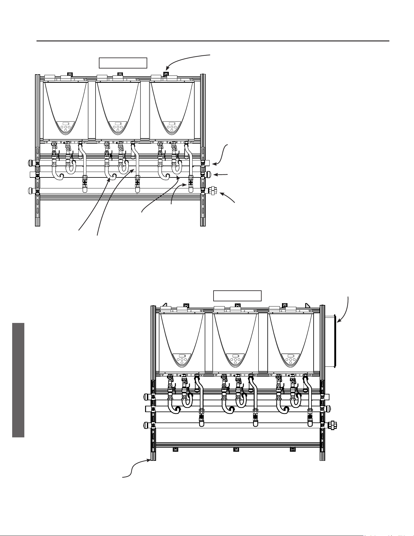
Cap*
Cap*
Hot out
Cold In
Cap
Gas In
End Cap Installaon Example
* Copper end caps are preferred and are field sup-
plied. They are not included with the assembly.
Figure 4: Cap open end of each manifold.
On-Demand Rack System • 7
INSTALLATION
INSTALLATION
system at test pressures in excess of
1/2 psi (3.5 kPa).
• Each water heater must be isolated
from the gas supply piping system
by closing its manual shuto valve
during any pressure tesng of that
system at test pressures equal to or
less than 1/2 psi (3.5 kPa).
7
Connect the
Power Supply
• Conrm that the installaon
complies with local electrical code
requirements. In the absence of
such requirements, follow the
Naonal Electrical Code ANSI/NFPA
70 (current edion) in the U.S. or
CSA C22.1 Canadian Electrical Code,
Part 1 (current edion) in Canada.
• Indoor models include a factory
installed, 6-foot (1.83m) long power
cord.
• Outdoor models must be hard wired.
• The water heaters require 120 VAC,
60 Hz electrical power supply that is
properly grounded.
• The electrical connecon must
provide a means of disconnecon
(to terminate power to the water
heaters for servicing and safety
purposes). Also, the water heaters
must be electrically grounded. Do
not aach the ground wire to either
the gas or water piping. Installaon
must comply with all code
requirements.
• Power Requirements
One 15 amp breaker can adequately
protect up to seven water heaters.
Example:
Number of
Heaters
Breaker Size
(Amps)
Number of
Breakers
1 to 7 15A 1
8 to 14 15A 2
15 to 20 15A 3
• Refer to the water heaters’
Installaon Manual and Owner’s
Guide for instrucons.
8
Configure the
System
If your rack system contains up to
four water heaters, configure it with
the Easy-Link System. Refer to the
water heaters’ Installation Manual and
Owner’s Guide for instructions.
However, if your rack system contains
five or more water heaters, we
strongly recommend that you install
and configure a multi-unit controller
(part number 100112691).
• A mul-unit controller can connect
up to 20 water heaters, making it
easy to use mulple racks.
• The mul-unit controller is available
as an accessory item. It can be
ordered along with the rack system
or later through your local service
agency/installer.
• If a mul-unit controller is ordered
with a wall mount or free standing
(in-line) system, it can be installed
on either end of the assembly.
However, a controller-mounng
kit is necessary to complete
the installaon. This kit is sold
separately and must be installed
on site by the installing contractor.
(Kit part number: 100211495.)
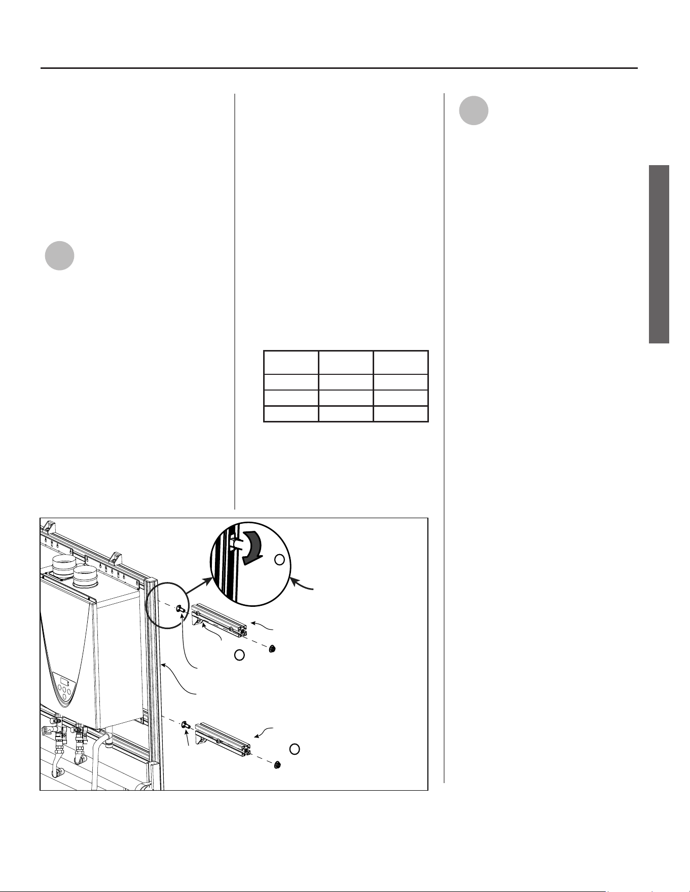
The mounng kit includes two
14-in. long mounng bars and two
mounng brackets.
ᴏ
Wall mounted rack systems only:
Install the bars onto either end
as shown in Figure 5.
ᴏ
Free standing rack systems: The
mul-unit controller may be
mounted on either side of the
rack or on a nearby wall. The
mounng hardware must be
eld supplied.
See also Piping Requirements, p. 5.
Nut
T-Bolt
A.) Place T-Bolt through bracket
hole as shown at le, then
start nut on opposite side.
Repeat for other bracket.
Bracket Hole
B.) Insert head of T-Bolt into
T-Channel slot, then
rotate it 90°.
Tighten nut.
(Torque: 25 Nm +/- 5%)
T-Channel Slot
T-Bolt
Nut
Mounng
Bar
Mounng
Bar
Insert, then
Rotate 90°
to lock.
C.) Determine locaon
of second mounng
bar. It must align
with the mounng
hole(s) on the
mul-unit
controller’s flange.
D.) Repeat steps A and B
to install the second
mounng bar.
A
B
C
Figure 5: Controller Bracket
Installation for Wall
Mounted Systems.

INSTALLATION
INSTALLATION
8 • On-Demand Rack System
INSTALLATION
INSTALLATION
9
Final Installation
Checklist
WARNING
• Do not install outdoor systems
indoors.
• Do not install indoor systems
outdoors.
• Improper installaon can cause
nausea or asphyxiaon, severe
injury or death from carbon
monoxide and ue gases
poisoning. Improper installaon
will void the product warranty.
□ Power Supply:
ᴏ
Conrm that the power
supply is 120 VAC (60 Hz) and
that the circuit is properly
grounded. Refer to the Power
Requirements table on page
7.
ᴏ
Does the electrical connecon
provide a means of
disconnecon (to terminate
power to the water heaters for
servicing and safety purposes)?
ᴏ
Make sure that the installaon
complies with local electrical
code requirements. In the
absence of such requirements,
follow the Naonal Electrical
Code ANSI/NFPA 70 (current
edion) in the U.S. or CSA C22.1
Canadian Electrical Code, Part 1
(current edion) in Canada.
□ Gas Supply:
ᴏ
Conrm that the water heaters
are rated for the type of gas that
is supplied.
ᴏ
Ensure that the gas supply line
is equipped with a manual gas
shut-o valve.
ᴏ
Ensure that air and debris are
purged from the gas line.
ᴏ
Check the gas lines for leaks.
Correct any that are found.
ᴏ
Verify that the gas inlet pressure
is within limits.
ᴏ
Make sure that the installaon
complies with all local codes.
In the absence of local codes,
follow the Naonal Fuel Gas
Code, ANSI Z223.1/NFPA 54
(current edion) in the USA, or in
Canada, follow CAN/CSA B149.1,
Natural Gas and Propane
Installaon Code (current
edion).
□ Water Supply:
ᴏ
Before operaon, ush the
water line at each water heater
to remove debris, then purge
the air from each line.
ᴏ
Ensure that water hardness
levels do not exceed 7 grains
per gallon (120 ppm) for single
family domesc applicaons or
more than 4 grains per gallon
(70 ppm) for all other types
of applicaons. Avoid hard
water scaling by proper water
treatment, if necessary.
ᴏ
Ensure that no pool water, spa
water, or chemically treated
water is introduced into the
water supply. Only potable
water can be used with these
water heaters. Refer to the
water heaters’ manuals for
more informaon.
ᴏ
Ensure that water pH levels are
between 6.5 and 8.5.
ᴏ
Is the water supply taken from
a well? If so, consult with a local
water quality expert before
water is treated.
ᴏ
Damage caused by water quality
is not covered by the warranty.
□ Venng, Air Supply, and Clearances:
ᴏ
Ensure that the water heaters
are not subject to corrosive
agents in the air. Also, ensure
that the area around the water
heaters is dust- and debris-free.
ᴏ
Ensure that venng is installed
according to the water
heaters’ installaon manuals
and the vent manufacturer’s
instrucons.
ᴏ
Are water heater clearances
observed? (Refer to the water
heaters’ Installaon Manual and
Owner’s Guide.)
ᴏ
Are vent terminaon and air
intake clearances observed?
(Refer to the water heaters’
Installaon Manual and
Owner’s Guide.)
ᴏ
Verify that adequate
combuson air will be available
to the water heaters at all
mes. Refer to the water
heaters’ Installaon Manual
and Owner’s Guide. Installaon
must also comply with local
codes. In the absence of local
codes, comply with the Naonal
Fuel Gas Code, ANSI Z223.1/
NFPA 54 (current edion) in
the USA, or in Canada, CAN/
CSA B149.1, Natural Gas and
Propane Installaon Code
(current edion).
□ Control System:
ᴏ
If your installaon includes up
to four water heaters, make
sure that the Easy-Link System
is congured properly. Refer to
the water heaters’ Installaon
Manual and Owner’s Guide for
instrucons.
ᴏ
If your installaon includes
ve or more water heaters,
make sure that the mul-unit
controller is installed and
congured properly. (Refer
to the Mul-Unit Controller
Installaon Manual.)
□ When installaon is complete,
verify proper operaon. If you have
quesons or need assistance, please
call toll-free: 877-737-2840.
On-Demand Rack System • 9
INSTALLATION
INSTALLATION
INSTALLATION
INSTALLATION
RACK #3 RACK #1RACK #2
COLD HEADER COLD HEADER
Hot Water
Outlet
H
O
T
H
O
T
HOT HEADERHOT HEADER
H
O
T
Cold
Water
Inlet
Expansion
Tank
Gas
Supply
G
A
S
G
A
S
G
A
S
GAS HEADER
G
A
S
G
A
S
CO
L
D
CO
L
D
CO
L
D
Shut Off/
Isolaon
Valve
Check
Valve
Union
Pressure
Relief
Valve
GAS HEADER
NOTES:
1. HEADERS MUST BE SIZED FOR TOTAL CAPACITY. WATER LINES SHOULD BE GREATER THAN 2 INCHES.
2. GAS SUPPLY HEADER MUST BE SIZED BY CURRENT METHODS PERSUANT TO NFPA 54 AND TO SUPPLY TOTAL
MAXIMUM INPUT FOR ALL WATER HEATERS.
3. IF THE APPLICATION CALLS FOR RECIRCULATION, INSTALL THE RECIRCULATION PUMP AS SHOWN ABOVE.
THE RECIRCULATION PUMP SHOULD BE SIZED TO PROVIDE 2 TO 4 GPM PER ACTIVATED HEATER. THE PUMP
SHOULD BE CONTROLLED WITH AN AQUASTAT. REFER TO THE WATER HEATER’S SPECIFICATION SHEET FOR
PRESSURE DROP INFORMATION.
4. CHECK VALVE SHOWN AT INLET IS ONLY NEEDED IF A RECIRCULATION LINE IS INSTALLED.
INSTALLATION MUST FOLLOW ALL APPLICABLE CODE REQUIREMENTS.
Recirculaon
Pump
Pump
Check Valve
2
2
1
1
1
1
3
4
H C GAS H C GAS H C GASH C GAS H C GAS H C GASH C GAS H C GAS H C GAS
Figure 6: Piping schematic for more than six (6) water heaters. This schematic illustrates a reverse return setup.
Each rack system can comprise up to six water heaters. Note that the multi-unit controller can control
up to 20 water heaters.
10 • On-Demand Rack System
MAINTENANCE / SPECIFICATIONS
MAINTENANCE / SPECIFICATIONS
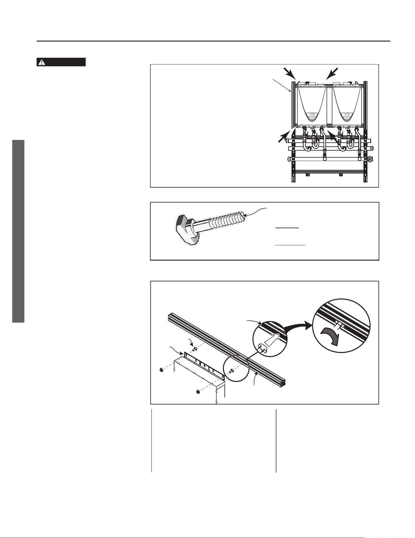
Free standing rack
systems:
• Each heater secured
by six bolts.
• Four are located as
shown at right.
Two addional bolts
are located top center
and boom center.
Wall mounted
rack systems:
Each heater
secured by
four T-bolts.
Figure 7: Location of nuts to be loosened / tightened. (Applies to each heater.)
Figure 8: T-bolt indicator (wall mounted racks only).
Grooved indicator runs parallel
with the bolt head.
• Removal: Indicator must be
parallel with T-Channel.
• Installaon: To secure water
heater, indicator must be
perpendicular to T-Channel.
T-Channel
(Side of Rail)
B.) Hold heater up to
rail and slide
T-Bolts into
T-Channel.
C.) Rotate a T-Bolt 90° to
lock it into place.
Tighten Nut. (Torque:
25 Nm +/- 5%.)
D.) Repeat at the three
remaining corners of
the water heater.
Flange
A.) Place T-Bolt through corner hole in
flange as shown below, then start nut
on opposite side. Repeat at all four
corners of heater.
Nut
Nut
T-Bolt
Figure 9: Securing the water heater to a wall mounted rack with T-bolts. Reverse the process to
remove a water heater.
MAINTENANCE
WARNING
• Read and follow all instrucons,
cauons, and warnings in the
water heaters’ Installaon Manual
and Owner’s Guide. Failure to do
so can lead to loss of life, personal
injury, and/or property damage.
• Water heaters may be hard water
scaled, which can cause leaks. For
the descaling procedure, service
technicians may reference the
water heater’s service handbook
(DIR 2000534342).
Replacing a Water
Heater
1. Turn OFF the power supply, the gas
supply, and the water supply.
2. Disconnect the power cable. If you
have an outdoor model, verify that
the electrical connections are not
powered by checking them with a
non-contact circuit tester.
ᴏ
Indoor Model:
Simply unplug the power cord
from the outlet.
ᴏ
Outdoor Model:
Disconnect the power cable
at the boom of the water
heater. See the water heater’s
Installaon Manual and
Owner’s Guide for details.
3. Disconnect the gas, cold water, and
hot water connections.
4. Remove the bolts as described
below. The locations are shown by
the arrows in Figure 7. If you have a
wall mounted rack, see Figure 9.
During this step, hold and support
the water heater so that it does
not fall.
ᴏ
Free Standing Rack:
Remove the six bolts that secure
the water heater.
ᴏ
Wall Mounted Rack:
Rotate each T-bolt 90-degrees to
release the water heater from
the rail. Look at the indicator
at the end of each T-bolt to
determine its orientaon. The
indicator should be parallel with
the T-channel. See Figure 8.
5. Lift the water heater from the rack.
6. Secure the new water heater to the

On-Demand Rack System • 11
MAINTENANCE / SPECIFICATIONS
MAINTENANCE / SPECIFICATIONS
rails. If the heater is being mounted
on a wall mounted rack, refer to
Figure 9.
7. Connect the water, gas, and
electrical connections as outlined
in the water heater’s Installation
Manual and Owner’s Guide.
8. Return the water heater to service
and verify proper operation.
Troubleshooting and
Service Procedures
For troubleshooting or service
information, refer to the water
heaters’ Installation Manual and
Owner’s Guide. Service technicians
may also reference the water heater’s
service handbook (DIR 2000534342).
12 • On-Demand Rack System
MAINTENANCE / SPECIFICATIONS
MAINTENANCE / SPECIFICATIONS
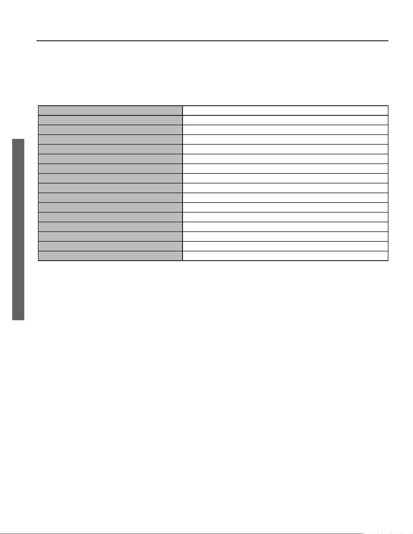
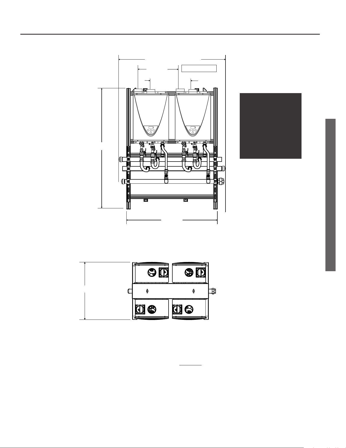
SPECIFICATIONS: WALL MOUNT (42” FRAME WIDTH)
Two Units
Heater
CT-199, IN/OS*, NG/LP, 199,000 BTU/h
Number of Heaters
2
Total Input (BTU/h)
398,000
Max. Flow at 50°F ΔT (gpm)
15.2
Max. Flow at 60°F ΔT (gpm)
12.6
Max. Flow at 70°F ΔT (gpm)
10.8
Max. Flow at 80°F ΔT (gpm)
9.4
Max. Flow at 90°F ΔT (gpm)
8.4
Max. Flow at 100°F ΔT (gpm)
7.6
Rack/Frame Dimensions
Refer to the next page.
Frame Material
AW-6063 T66 Extruded Alloy with Clear Annodized Coating
Cold Water Header
2” dia. Copper Tube
Hot Water Header
2” dia. Copper Tube
Gas Line Header
1-1/2” Sch. 40, A53A, Blk
Water Connectors to Heaters
2’ long, 3/4” dia. Stainless Steel Flex Line
Gas Connectors to Heaters
2’ long, 3/4” dia. CSST
* IN - Indoor Model; OS - Outdoor Model
On-Demand Rack System • 13
MAINTENANCE / SPECIFICATIONS
MAINTENANCE / SPECIFICATIONS
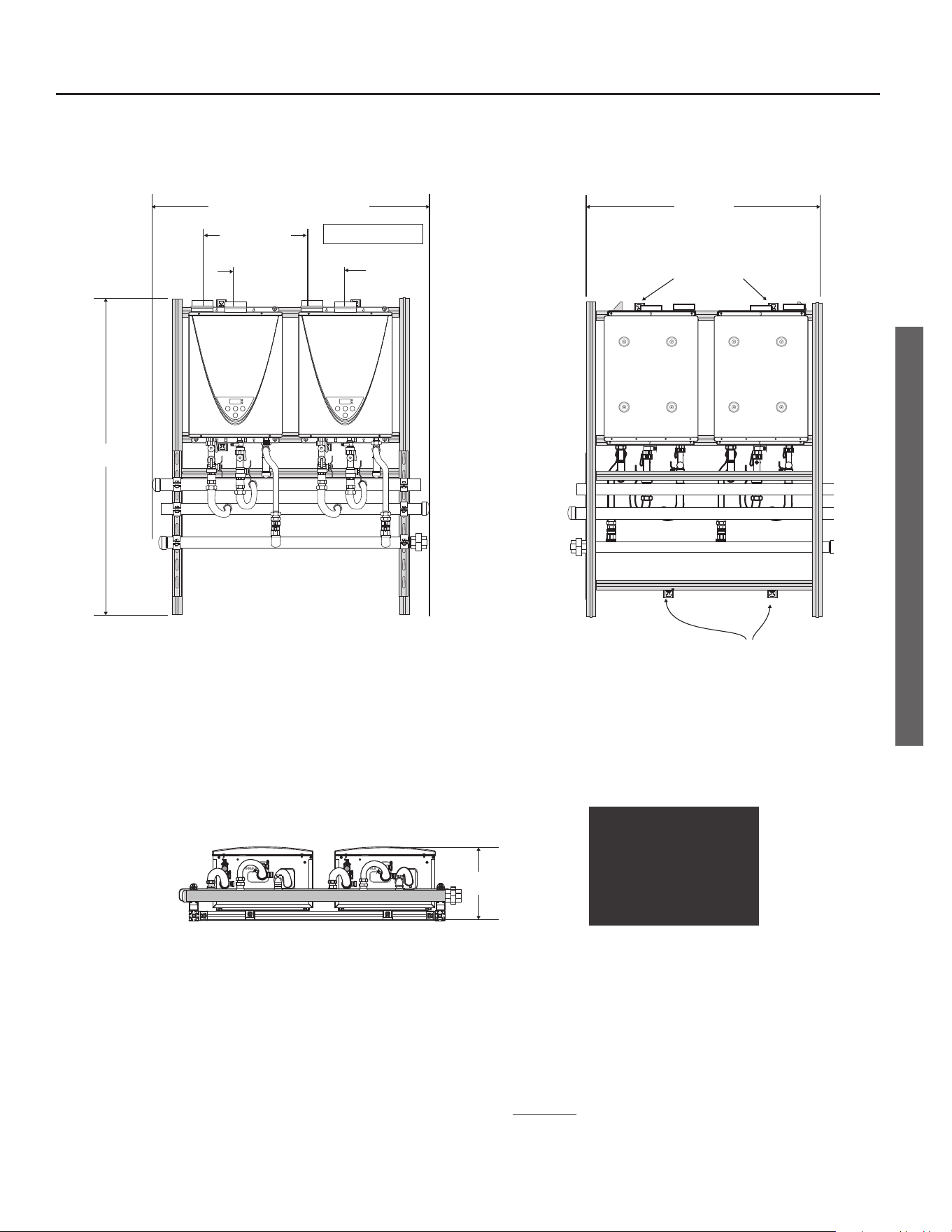
Back
Front
Boom
57.00 in.
SEE NOTE 2.
SEE NOTE 2.
NOTES:
1. TOP-MOUNTED AIR SUPPLY INLET/EXHAUST VENTS ARE USED WITH INDOOR MODELS ONLY.
2. MOUNTING BRACKETS ADJUST HORIZONTALLY ALONG CHANNEL SLOTS.
3. INDOOR AND OUTDOOR RACK SYSTEMS HAVE IDENTICAL DIMENSIONS. EXCEPTION: INDOOR MODELS HAVE
TOP-MOUNTED INTAKES AND EXHAUSTS. OUTDOOR MODELS DO NOT.
42.00 in.
13.02 in.
20.75 in.
(INLETS)
20.75 in.
(EXHAUSTS)
SEE NOTE 1.
Pipe Lengths:
46 in. MAX. plus fings*
* Fings to be field supplied.
NOTICE:
Indoor models are shown in
these graphics. However, some
configurations include outdoor
models. The dimensions are
the same except as noted in
the footnotes below.
14 • On-Demand Rack System
MAINTENANCE / SPECIFICATIONS
MAINTENANCE / SPECIFICATIONS
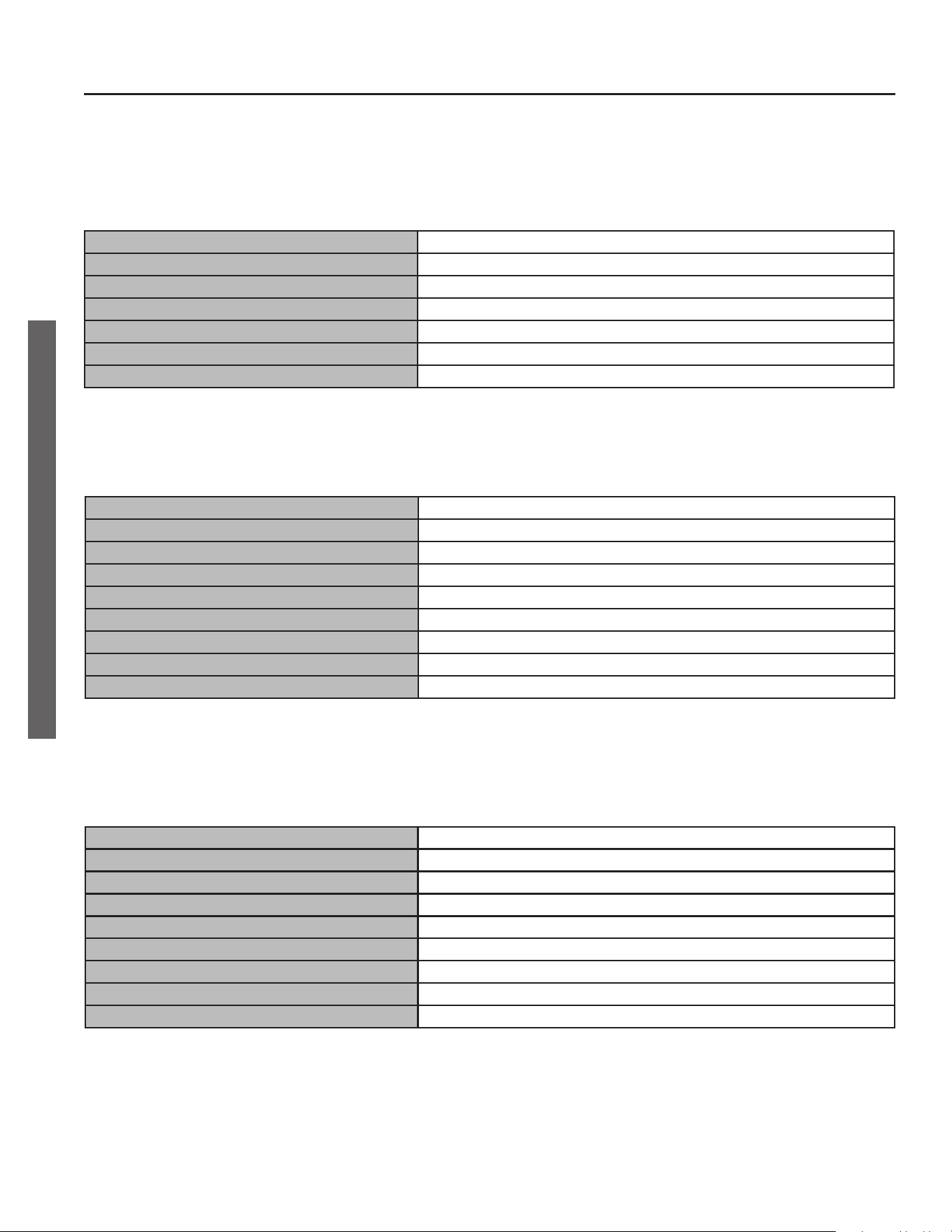
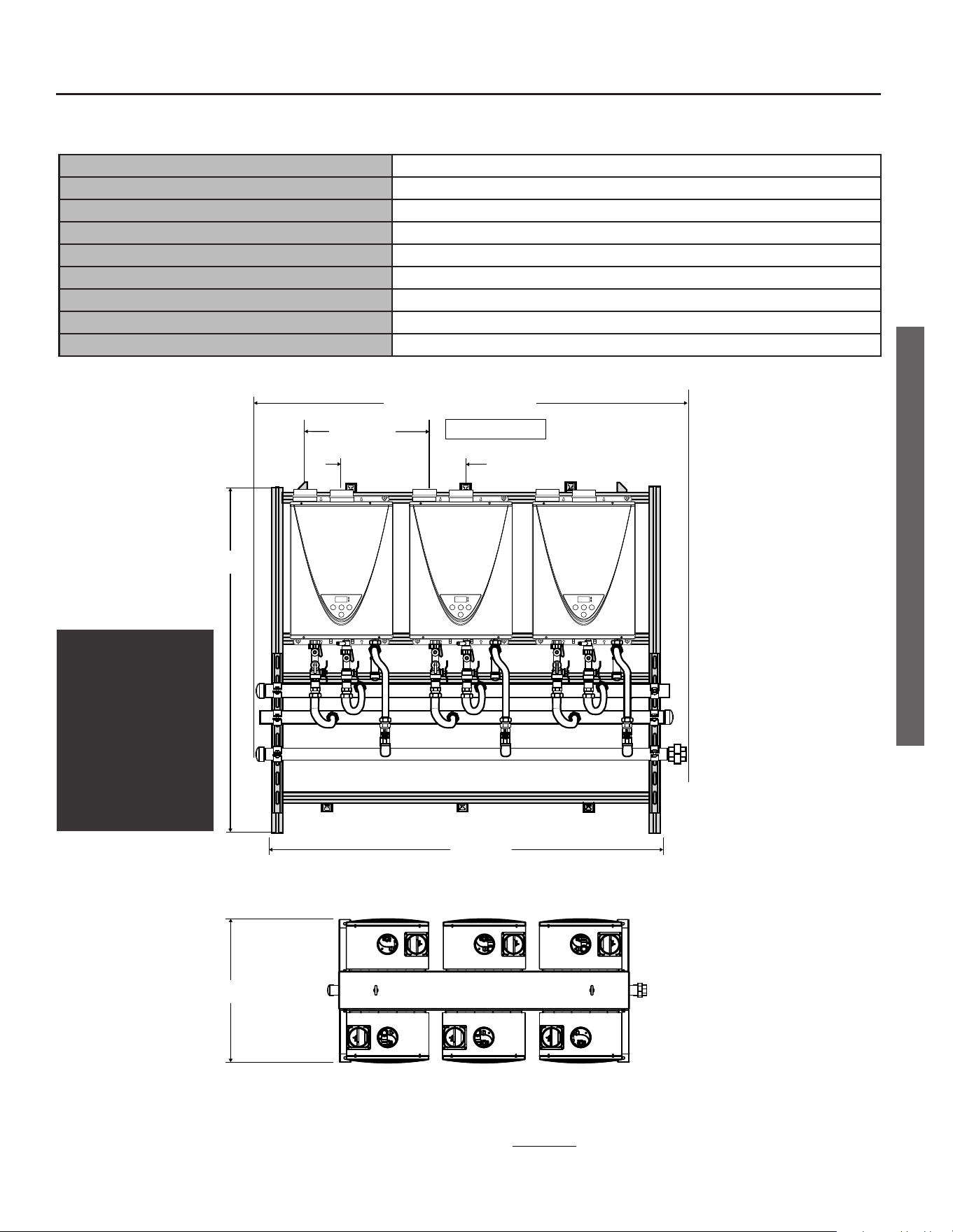
SPECIFICATIONS: WALL MOUNT (62.81” FRAME WIDTH)
Three Units
Heater
CT-199, IN/OS*, NG/LP, 199,000 BTU/h
Number of Heaters
3
Total Input (BTU/h)
597,000
Max. Flow at 50°F ΔT (gpm)
22.8
Max. Flow at 60°F ΔT (gpm)
18.9
Max. Flow at 70°F ΔT (gpm)
16.2
Max. Flow at 80°F ΔT (gpm)
14.1
Max. Flow at 90°F ΔT (gpm)
12.6
Max. Flow at 100°F ΔT (gpm)
11.4
* IN - Indoor Model; OS - Outdoor Model
Two Units
Heater
CT-199, IN/OS*, NG/LP, 199,000 BTU/h
Number of Heaters
2
Total Input (BTU/h)
398,000
Max. Flow at 50°F ΔT (gpm)
15.2
Max. Flow at 60°F ΔT (gpm)
12.6
Max. Flow at 70°F ΔT (gpm)
10.8
Max. Flow at 80°F ΔT (gpm)
9.4
Max. Flow at 90°F ΔT (gpm)
8.4
Max. Flow at 100°F ΔT (gpm)
7.6
* IN - Indoor Model; OS - Outdoor Model
Rack/Frame Dimensions
Refer to the next page.
Frame Material
AW-6063 T66 Extruded Alloy with Clear Annodized Coating
Cold Water Header
2” dia. Copper Tube
Hot Water Header
2” dia. Copper Tube
Gas Line Header
1-1/2” Sch. 40, A53A, Blk
Water Connectors to Heaters
2’ long, 3/4” dia. Stainless Steel Flex Line
Gas Connectors to Heaters
2’ long, 3/4” dia. CSST
Basics (all configurations)
On-Demand Rack System • 15
MAINTENANCE / SPECIFICATIONS
MAINTENANCE / SPECIFICATIONS
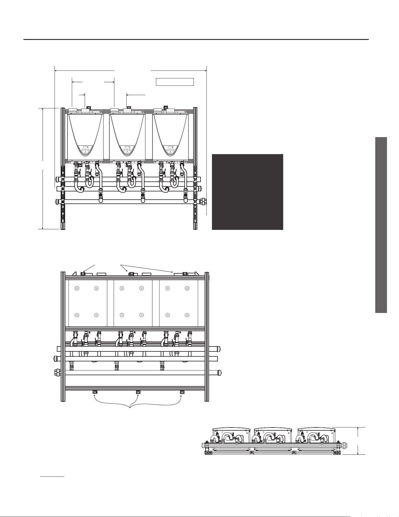
Back
Front
Boom
57.00 in.
SEE NOTE 2.
SEE NOTE 2.
NOTES:
1. TOP-MOUNTED AIR SUPPLY INLET/EXHAUST VENTS ARE USED WITH
INDOOR MODELS ONLY.
2. MOUNTING BRACKETS ADJUST HORIZONTALLY ALONG CHANNEL SLOTS.
3. INDOOR AND OUTDOOR RACK SYSTEMS HAVE IDENTICAL DIMENSIONS.
EXCEPTION: INDOOR MODELS HAVE TOP-MOUNTED INTAKES AND
EXHAUSTS. OUTDOOR MODELS DO NOT.
62.81 in.
13.02 in.
20.75 in.
(ALL INLETS)
20.75 in.
(ALL EXHAUSTS)
SEE NOTE 1.
Pipe Lengths:
66 in. MAX. plus fings*
* Fings to be field supplied.
NOTICE:
• Your configuration may
include two or three water
heaters.
• Indoor models are shown in
these graphics. However,
some configurations include
outdoor models. The
dimensions are the same
except as noted in the
footnotes below.
16 • On-Demand Rack System
MAINTENANCE / SPECIFICATIONS
MAINTENANCE / SPECIFICATIONS
SPECIFICATIONS: FREE STANDING (41.54” FRAME WIDTH)
Basics (all configurations)
Rack/Frame Dimensions
Refer to the next page.
Frame Material
Marine grade aluminum 6061-T6 or 5052-H32 (0.08 in. thickness)
Cold Water Header
2” dia. Copper Tube
Hot Water Header
2” dia. Copper Tube
Gas Line Header
1-1/2” Sch. 40, A53A, Blk
Water Connectors to Heaters
2’ long, 3/4” dia. Stainless Steel Flex Line
Gas Connectors to Heaters 2’ long, 3/4” dia. CSST
* IN - Indoor Model; OS - Outdoor Model
Heater
CT-199, IN/OS*, NG/LP, 199,000 BTU/h
Number of Heaters
2
Total Input (BTU/h)
398,000
Max. Flow at 50°F ΔT (gpm)
15.2
Max. Flow at 60°F ΔT (gpm)
12.6
Max. Flow at 70°F ΔT (gpm)
10.8
Max. Flow at 80°F ΔT (gpm)
9.4
Max. Flow at 90°F ΔT (gpm)
8.4
Max. Flow at 100°F ΔT (gpm)
7.6
* IN - Indoor Model; OS - Outdoor Model
Two Units
Heater
CT-199, IN/OS*, NG/LP, 199,000 BTU/h
Number of Heaters
3
Total Input (BTU/h)
597,000
Max. Flow at 50°F ΔT (gpm)
22.8
Max. Flow at 60°F ΔT (gpm)
18.9
Max. Flow at 70°F ΔT (gpm)
16.2
Max. Flow at 80°F ΔT (gpm)
14.1
Max. Flow at 90°F ΔT (gpm)
12.6
Max. Flow at 100°F ΔT (gpm)
11.4
* IN - Indoor Model; OS - Outdoor Model
Three Units
Heater
CT-199, IN/OS*, NG/LP, 199,000 BTU/h
Number of Heaters
4
Total Input (BTU/h)
796,000
Max. Flow at 50°F ΔT (gpm)
30.4
Max. Flow at 60°F ΔT (gpm)
25.2
Max. Flow at 70°F ΔT (gpm)
21.6
Max. Flow at 80°F ΔT (gpm)
18.8
Max. Flow at 90°F ΔT (gpm)
16.8
Max. Flow at 100°F ΔT (gpm)
15.2
* IN - Indoor Model; OS - Outdoor Model
Four Units
On-Demand Rack System • 17
MAINTENANCE / SPECIFICATIONS
MAINTENANCE / SPECIFICATIONS
Front
Top
53.09 in.
Pipe Lengths:
46 in. MAX. plus fings*
NOTES:
1. TOP-MOUNTED AIR SUPPLY INLET/EXHAUST VENT ARE USED WITH INDOOR MODELS ONLY.
2. INDOOR AND OUTDOOR RACK SYSTEMS HAVE IDENTICAL DIMENSIONS.
EXCEPTION: INDOOR MODELS HAVE
TOP-MOUNTED INTAKES AND EXHAUSTS. OUTDOOR MODELS DO NOT.
41.54 in.
20.75 in.
(INLETS)
20.75 in.
(EXHAUSTS)
SEE NOTE 1.
30.50 in.
*Fings to be field supplied.
NOTICE:
• Your configuration may
include two, three, or four
water heaters.
• Indoor models are shown in
these graphics. However,
some configurations include
outdoor models. The
dimensions are the same
except as noted in the
footnotes below.
18 • On-Demand Rack System
MAINTENANCE / SPECIFICATIONS
MAINTENANCE / SPECIFICATIONS
SPECIFICATIONS: FREE STANDING (62.29” FRAME WIDTH)
Basics (all configurations)
Rack/Frame Dimensions
Refer to the next page.
Frame Material
Marine grade aluminum 6061-T6 or 5052-H32 (0.08 in. thickness)
Cold Water Header
2” dia. Copper Tube
Hot Water Header
2” dia. Copper Tube
Gas Line Header
1-1/2” Sch. 40, A53A, Blk
Water Connectors to Heaters
2’ long, 3/4” dia. Stainless Steel Flex Line
Gas Connectors to Heaters 2’ long, 3/4” dia. CSST
* IN - Indoor Model; OS - Outdoor Model
Heater
CT-199, IN/OS*, NG/LP, 199,000 BTU/h
Number of Heaters
3
Total Input (BTU/h)
597,000
Max. Flow at 50°F ΔT (gpm)
22.8
Max. Flow at 60°F ΔT (gpm)
18.9
Max. Flow at 70°F ΔT (gpm)
16.2
Max. Flow at 80°F ΔT (gpm)
14.1
Max. Flow at 90°F ΔT (gpm)
12.6
Max. Flow at 100°F ΔT (gpm)
11.4
* IN - Indoor Model; OS - Outdoor Model
Three Units
Heater
CT-199, IN/OS*, NG/LP, 199,000 BTU/h
Number of Heaters
4
Total Input (BTU/h)
796,000
Max. Flow at 50°F ΔT (gpm)
30.4
Max. Flow at 60°F ΔT (gpm)
25.2
Max. Flow at 70°F ΔT (gpm)
21.6
Max. Flow at 80°F ΔT (gpm)
18.8
Max. Flow at 90°F ΔT (gpm)
16.8
Max. Flow at 100°F ΔT (gpm)
15.2
* IN - Indoor Model; OS - Outdoor Model
Four Units
Heater
CT-199, IN/OS*, NG/LP, 199,000 BTU/h
Number of Heaters
5
Total Input (BTU/h)
995,000
Max. Flow at 50°F ΔT (gpm)
38
Max. Flow at 60°F ΔT (gpm)
31.5
Max. Flow at 70°F ΔT (gpm)
27
Max. Flow at 80°F ΔT (gpm)
23.5
Max. Flow at 90°F ΔT (gpm)
21
Max. Flow at 100°F ΔT (gpm)
19
* IN - Indoor Model; OS - Outdoor Model
Five Units
On-Demand Rack System • 19
MAINTENANCE / SPECIFICATIONS
MAINTENANCE / SPECIFICATIONS
30.50 in.
Top
Front
53.09 in.
Pipe Lengths:
66 in. MAX. plus fings
NOTES:
1. TOP-MOUNTED AIR SUPPLY INLET/EXHAUST VENT ARE USED WITH INDOOR MODELS ONLY.
2. INDOOR AND OUTDOOR RACK SYSTEMS HAVE IDENTICAL DIMENSIONS.
EXCEPTION: INDOOR MODELS HAVE
TOP-MOUNTED INTAKES AND EXHAUSTS. OUTDOOR MODELS DO NOT.
62.29 in.
20.75 in.
(INLETS)
20.75 in.
(EXHAUSTS)
SEE NOTE 1.
Heater
CT-199, IN/OS*, NG/LP, 199,000 BTU/h
Number of Heaters
6
Total Input (BTU/h)
1,194,000
Max. Flow at 50°F ΔT (gpm)
45.6
Max. Flow at 60°F ΔT (gpm)
37.8
Max. Flow at 70°F ΔT (gpm)
32.4
Max. Flow at 80°F ΔT (gpm)
28.2
Max. Flow at 90°F ΔT (gpm)
25.2
Max. Flow at 100°F ΔT (gpm)
22.8
* IN - Indoor Model; OS - Outdoor Model
Six Units
NOTICE:
• Your configuration may
include three, four, five,
or six water heaters.
• Indoor models are
shown in these graphics.
However, some
configurations include
outdoor models. The
dimensions are the same
except as noted in the
footnotes below.
20 • On-Demand Rack System
REPLACEMENT PARTS
REPLACEMENT PARTS
GAS SHUTOFF
VALVE (8)
GAS MANIFOLD (4)
HOT WATER
MANIFOLD (3)
COLD WATER
MANIFOLD (2)
WALL MOUNTING
BRACKET (1)
FOOT (10)
GAS
FLEX LINE (6)
HOT WATER
FLEX LINE (5)
COLD WATER
FLEX LINE (7)
MULTI-UNIT CONTROLLER (9)
(FOR 5+ WATER HEATERS)
WALL MOUNT
FREE STANDING
On-Demand Rack System • 21
REPLACEMENT PARTS
ITEM DESCRIPTION
1 Wall mounting bracket (wall mounted models only)
2 Manifold, cold water
3 Manifold, hot water
4 Manifold, gas
5 Flex line, hot water
6 Flex line, gas
7 Flex line, cold water
8 Gas shutoff valve
9 Multi-unit controller (for 5+ water heaters)
10 Foot (free standing models)
11 Wall mount (wall mounted models)
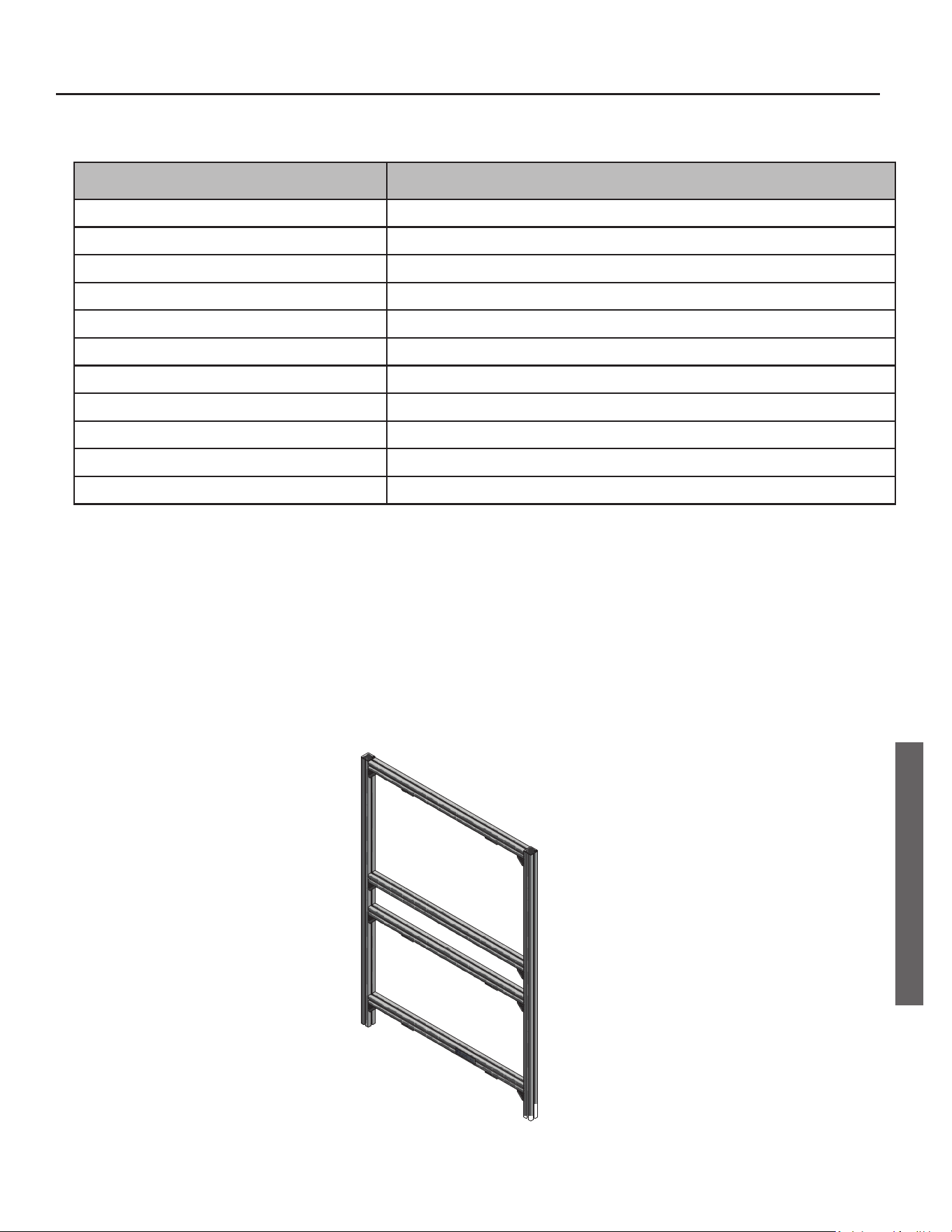
WALL MOUNT / UPRIGHT FRAME (11)

22 • On-Demand Rack System
NOTES
NOTES

On-Demand Rack System • 23
NOTES
NOTES

Copyright © 2020. All rights reserved.
Questions? Call toll free: 877-737-2840.