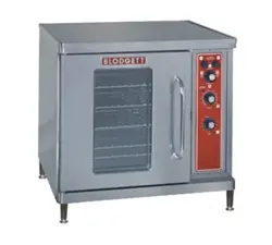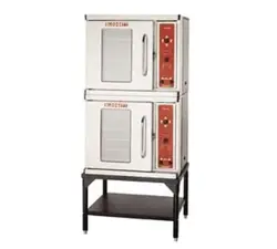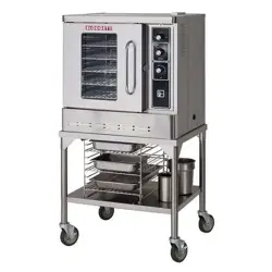

DFG-50
CONVECTION OVEN
INSTALLATION - OPERATION - MAINTENANCE
BLODGETT OVEN COMPANY
www.blodgett.com
42 Allen Martin Drive, Essex Junction, Vermont 05452 USA Telephone: (802) 658-6600 Fax: (802)864-0183
PN 17355 Rev W (3/18)
© 2018 - G.S. Blodgett Corporation

Your Service Agency’s Address:
Model
Serial number
Oven installed by
Installation checked by

TABLE OF CONTENTS
INSTALLATION
Oven Description and Specications ....................................... 2
Delivery and Location .................................................... 3
Stand Assembly.......................................................... 4
Oven Assembly .......................................................... 6
Oven Assembly to Stand .............................................. 6
4” (10cm) Leg Attachment ............................................. 7
Caster Installation .................................................... 7
Oven leveling ........................................................ 7
Ventilation ............................................................... 8
Utility Connections - Standards and Codes ................................ 10
Gas Connection......................................................... 11
Gas Piping.......................................................... 11
Pressure Regulation and Testing ...................................... 12
Gas Hose Restraint ................................................. 13
Electrical Connection .................................................... 14
Initial Startup ........................................................... 15
OPERATION
Safety Information ....................................................... 16
Solid State Manual Control ............................................... 17
Solid State Digital Control ................................................ 18
CH-Pro3 (Solid State Programmable Digital Control) ....................... 20
Blodgett IQ2™ Vision Control ............................................ 23
How Cook & Hold Works ................................................. 33
General Guidelines for Operating Personnel ............................... 34
Suggested Times and Temperatures ...................................... 35
MAINTENANCE
Cleaning and Preventative Maintenance .................................. 36
Troubleshooting Guide .................................................. 37
IMPORTANT
WARNING: Improper installa-
tion, adjustment, alternation,
service or maintenance can
cause property damage, in-
jury or death. Read the instl-
lation, operation and mainte-
nance instructions thoroughly
before installing or servicing
this equipment.
INSTRUCTIONS TO BE FOL-
LOWED IN THE EVENT THE
USER SMELLS GAS MUST BE
POSTED IN A PROMINENT LO-
CATION. This information may
be obtained by contacting your
local gas supplier.
FOR YOUR SAFETY
Do not store or use gasoline or
other ammable vapors or liq-
uids in the vicinity of this or any
other appliance.
The information contained in this
manual is important for the prop-
er installation, use, and mainte-
nance of this oven. Adherence
to these procedures and instruc-
tions will result in satisfactory
baking results and long, trou-
ble free service. Please read
this manual carefully and retain
it for future reference.
ERRORS: Descriptive, typo-
graphic or pictorial errors are
subject to correction. Speci-
cations are subject to change
without notice.
2
Installation
Oven Description and Specications
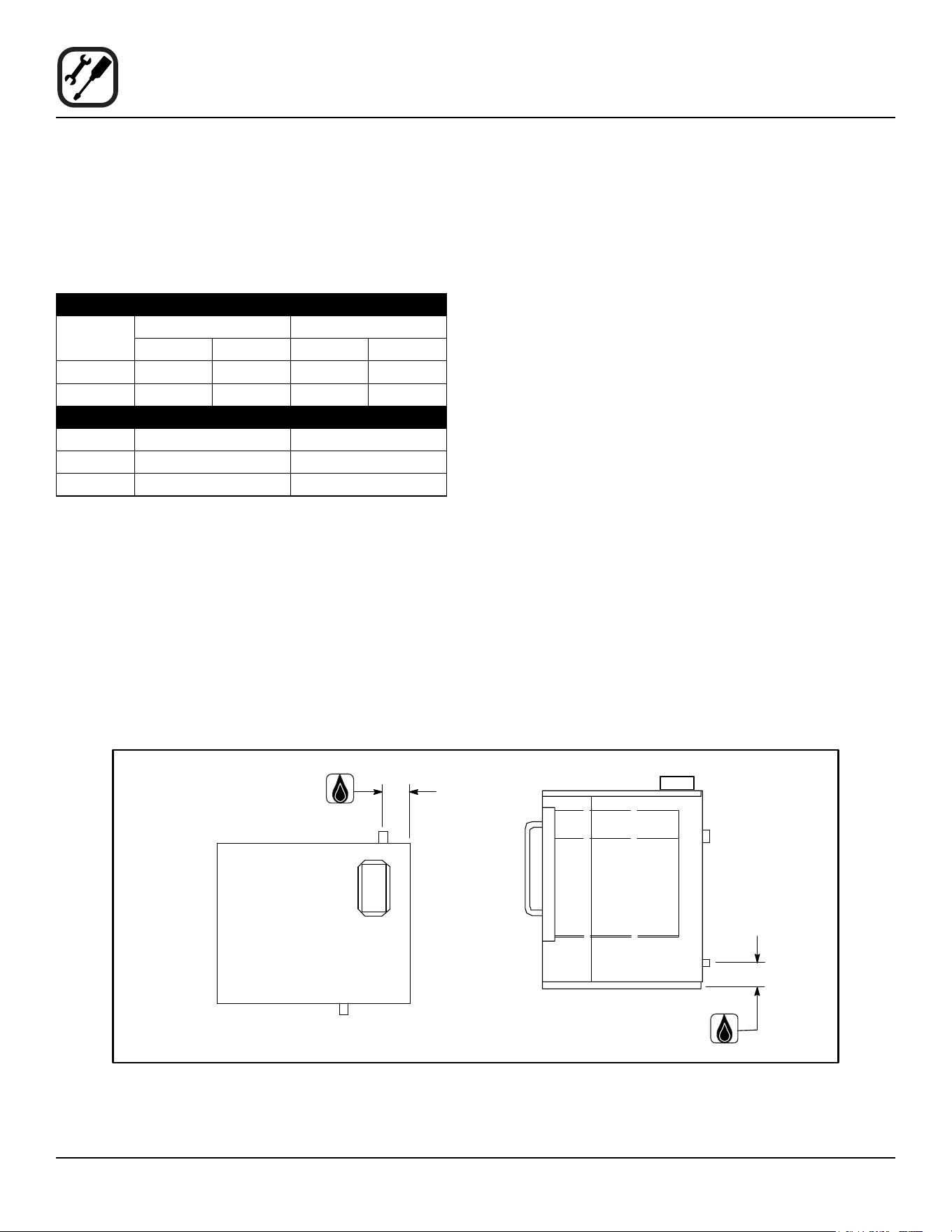
GAS RATINGS - DFG-50
Natural Gas Propane
US Units SI Units US Units SI Units
U.S., Canada and General Export
Heating Value 1000 BTU/cu.ft. 37.3 MJ/m3 2550 BTU/cu. ft. 95.0 MJ/m3
Specic Gravity (air=1.0) 0.63 0.63 1.53 1.53
Gas Manifold Pressure 3.5” W.C. .87 kPa 10” W.C. 2.49 kPa
Oven Input 27,500 BTU/hr
34,500 BTU/hr
8.1 kW
10.1 kW
27,500 BTU/hr
34,500 BTU/hr
8.1 kW
10.1 kW
Main Burner Orice Size 38 MTD*
32 MTD*
2.6 mm
2.9 mm
1/16” dia.
50 MTD*
1.6 mm
1.75 mm
Pilot Burner Orice Size .021” dia. .55 mm .011” dia. .28 mm
Australia
Oven Input — 32 MJ — 32 MJ
Main Burner Orice Size 38 MTD* 2.6 mm 1/16” dia. 1.6 mm
Gas Manifold Pressure — .87 kPa — 2.49 kPa
NOTE: * - Multiple Twist Drill
Cooking in a convection oven diers from cooking in a
conventional deck or range oven since heated air is con-
stantly recirculated over the product by a fan in an en-
closed chamber. The moving air continually strips away
the layer of cool air surrounding the product, quickly al-
lowing the heat to penetrate. The result is a high qual-
ity product, cooked at a lower temperature in a shorter
amount of time.
Blodgett convection ovens represent the latest advance-
ment in energy eciency, reliability, and ease of opera-
tion. Heat normally lost, is recirculated within the cooking
chamber before being vented from the oven: resulting in
substantial reductions in energy consumption and en-
hanced oven performance.

3
Installation
Delivery and Location
DELIVERY AND INSPECTION
All Blodgett ovens are shipped in containers to prevent
damage. Upon delivery of your new oven:
• Inspect the shipping container for external damage.
Any evidence of damage should be noted on the
delivery receipt which must be signed by the driver.
• Uncrate the oven and check for internal damage.
Carriers will accept claims for concealed damage if
notied within fteen days of delivery and the ship-
ping container is retained for inspection.
The Blodgett Oven Company cannot assume responsibil-
ity for loss or damage suered in transit. The carrier as-
sumed full responsibility for delivery in good order when
the shipment was accepted. We are, however, prepared
to assist you if ling a claim is necessary.
OVEN LOCATION
The well planned and proper placement of your oven will
result in long term operator convenience and satisfactory
performance.
The following clearances must be maintained between
the oven and any combustible or non-combustible con-
struction.
• Oven body right side - 6” (15 cm)
• Oven body left side - 6” (15 cm)
• Oven body back - 6” (15 cm)
• Single or stacked body bottom - 6” (15 cm)
The following clearances must be available for servicing.
• Oven body sides - 12” (30 cm)
• Oven body back - 12” (30 cm)
NOTE: On gas models, routine servicing can usually be
accomplished within the limited movement pro-
vided by the gas hose restraint. If the oven needs
to be moved further from the wall, the gas must
rst be turned o and disconnected from the oven
before removing the restraint. Reconnect the re-
straint after the oven has been returned to its nor-
mal position.
It is essential that an adequate air supply to the oven be
maintained to provide a sucient ow of combustion and
ventilation air.
• Place the oven in an area that is free of drafts.
• Keep the oven area free and clear of all combus-
tibles such as paper, cardboard, and ammable
liquids and solvents.
• Do not place the oven on a curb base or seal to
a wall. This will restrict the ow of air and prevent
proper ventilation. Tripping of the blower motor’s
thermal overload device is caused by an excessive
ambient temperature on the right side of the oven.
This condition must be corrected to prevent perma-
nent damage to the oven.
• The location must provide adequate clearance for
the air opening into the combustion chamber.
Before making any utility connections to this oven, check
the rating plate to be sure the oven specications are
compatible with the gas and electrical services supplied
for the oven.
1. Pull out control panel. The rating plate attached to the
inside of the control compartment.
• Do not place strong sources of heat such as open
ame ranges, griddles, or charbroilers near the
oven. If such an instance exists, it is highly recom-
mended to purchase a heat shield, available from
Blodgett.
• Note that if temperatures are too high, a safety shut-
down may occur.
• Failure to comply may invalidate the oven warranty.
4
Installation
Stand Assembly
STAND OPTIONS
Small Stands Without Shelves
• The 5-3/4” (15cm) stand is used for a single oven,
when short legs are required for countertop use.
• The 7” (18cm) stand is used for a double stacked
oven, when the oven is to be located on the oor.
Stands With Shelves
• Three stands, 16” (40cm), 19” (48cm), and 24”
(61cm) are available for dierent installation require-
ments.
• The 33” (84cm) stand is used for a single oven when
counter space is limited.
Open Stands With Racks
• The 24” (61cm) or 33” (84cm) open stands are avail-
able with a rack support system located below the
oven.
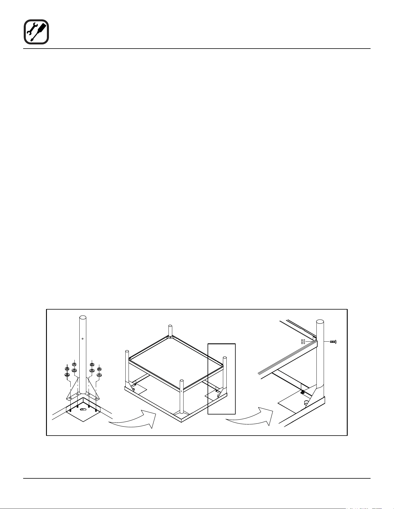
STAND ASSEMBLY
Small Stands Without Shelves
1. Place stand frame upside down on a work surface.
2. Attach one leg to each of the corner stud bolts on the
bottom of the stand top.
3. Place a lock washer and nut on each stud, and tight-
en securely.
Stands With Shelves
1. Place stand frame upside down on a work surface.
2. Attach one leg to each of the corner stud bolts on the
bottom of the stand top.
3. Place a lock washer and nut on each bolt, and tight-
en. DO NOT tighten leg bolts completely.
4. Place the shelf between the legs so that the smooth
top surface is facing the top of the stand.
5. Align the shelf holes with the bolt holes found near
the bottom of each leg.
6. Insert a carriage bolt from the outside of the leg,
through the leg, and through the shelf corner bracket.
7. Place a lock washer and nut on each bolt, and tighten
securely.
8. Tighten the leg frame bolts.
Figure 1
5
Installation
Stand Assembly
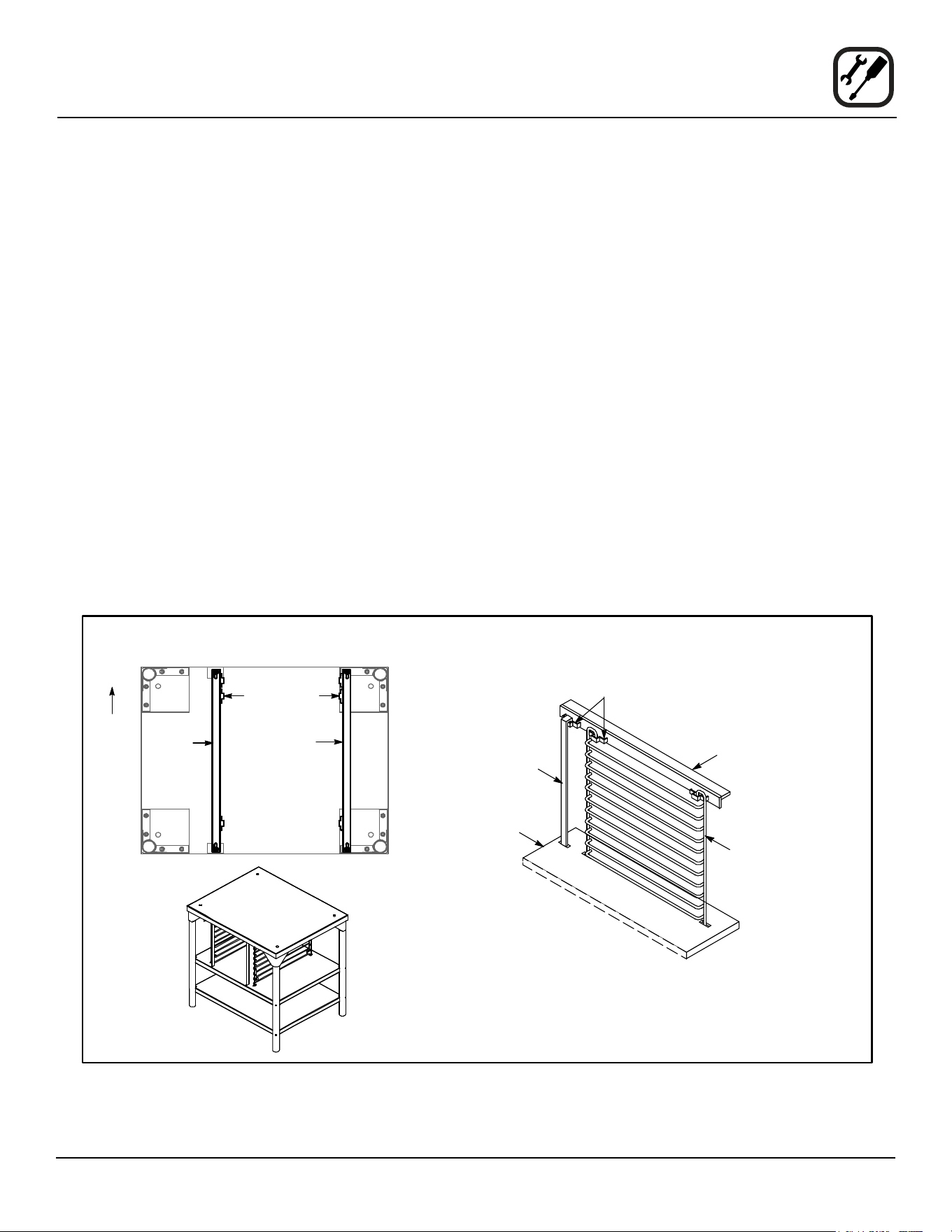
Open Stands With Shelves and Racks
1. Place stand frame upside down on a work surface.
2. Attach one leg to each of the corner stud bolts on the
bottom of the stand top.
3. Place a lock washer and nut on each bolt, and tight-
en. DO NOT tighten leg bolts completely.
4. Attach the rack support angles to the stud bolts on the
bottom of the stand top with the nuts provided.
Each support angle has 2 clips on one end and 1 clip
on the other end. The two clips should be at the back
of the stand facing toward the center.
IMPORTANT - Be sure the support angles and
clips are located correctly for your oven congu-
ration as shown.
5. Position the bottom shelf between the legs so that the
smooth top surface is facing the top of the stand.
6. Align the shelf holes with the bolt holes found near
the bottom of each leg.
7. Insert a carriage bolt from the outside of the leg,
through the leg, and through the shelf corner bracket.
8. Place a lock washer and nut on each bolt, and tighten
securely.
9. Repeat Steps 5-8 for the top shelf.
NOTE: Be sure the slots in the top shelf are aligned
with the support angles.
10. Insert the top of the rack stops into the two back clips
on the angle supports as shown. Insert the bottom of
the rack stops into the slots in the top shelf as shown.
11. Insert the rack supports into the remaining four clips
on the angle supports as shown. Insert the bottom
of the rack supports into the slots in the top shelf as
shown.
12. Tighten all loose bolts.
Figure 2
Underside of Stand Top
Left
Support
Angle
Right
Support
Angle
Top Shelf
(rear)
Support Angle
Rack
Support
Attach Rack Supports
and Rack Stops
Clips
Rack Stop
Clips
Proper Location of Support Angles
Rear of
Stand
6
Installation
Oven Assembly
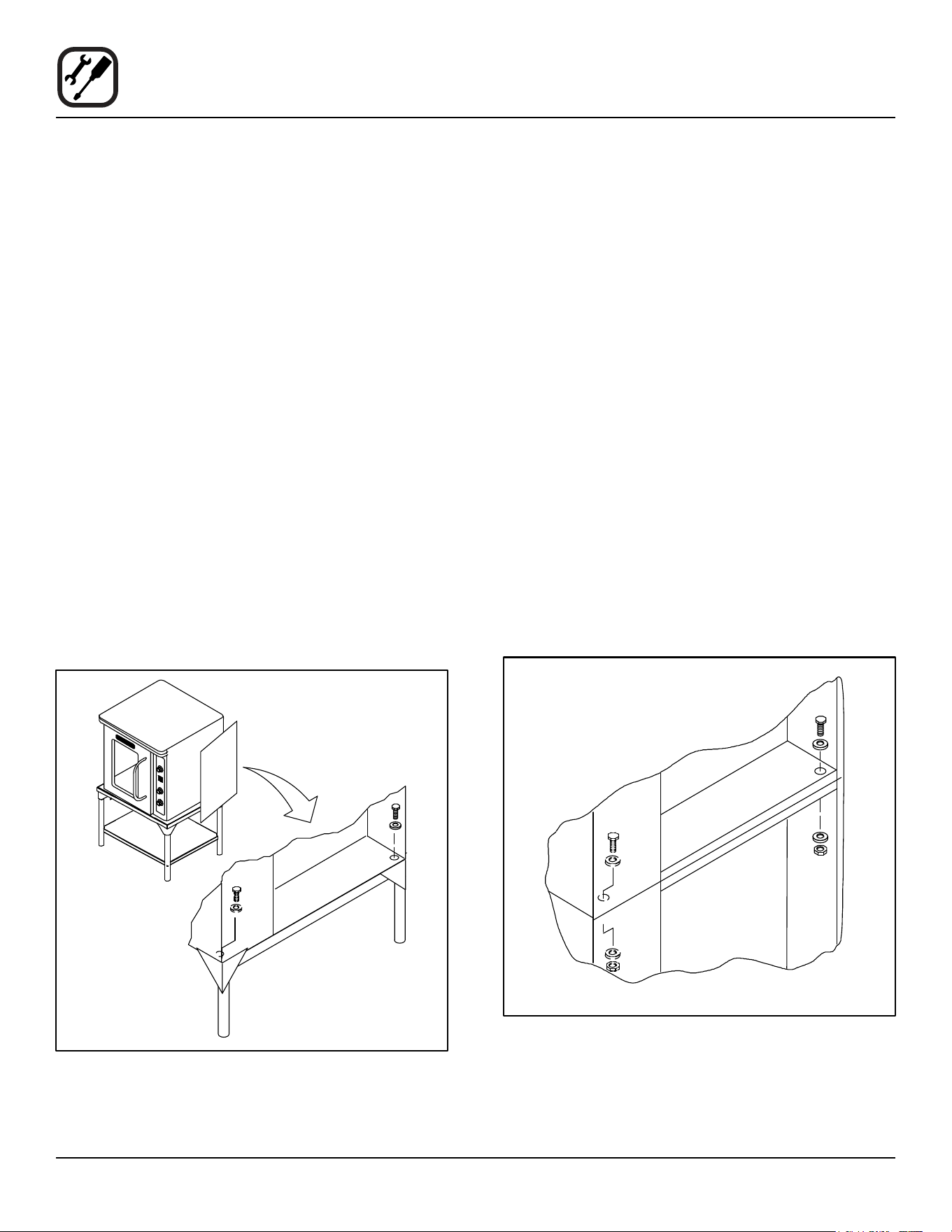
OVEN ASSEMBLY TO STAND
Single Section
1. Place the assembled stand in the location where the
oven is going to be used.
2. Remove the side control compartment cover and
open the front control panel of a single oven (or lower
section).
3. With a tool, punch out the knock-outs in the oven bot-
tom near each corner.
4. Set the oven on the stand. Center it to the frame.
5. Align the front, and rear bolt holes of the oven with the
bolt holes in the stand.
6. Insert a bolt and washer, from the top down through
each of the 2 holes.
7. Place a nut and washer on each of the 2 bolts, and
tighten securely.
8. Replace the oven’s side control compartment, and
close the front control panel.
NOTE: For single section ovens only. For double
stacked ovens this step will be completed
once the ovens are stacked.
Figure 3
Double Section
1. Assemble the lower section to the stand as described.
DO NOT replace the side control compartment or
close the front control panel.
2. With a tool, punch out the knock-outs in the oven top
of the lower oven.
3. Remove the side control compartment cover and
open the front control panel of the upper oven.
4. With a tool, punch out the knock-outs in the bottom of
the upper oven near each corner.
5. Set the upper oven on the lower oven.
6. Align the front, and rear bolt holes of the upper oven
with the bolt holes in the bottom oven.
7. Insert a bolt and washer, from the top down through
each of the 2 holes.
8. Place a nut and washer on each of the 2 bolts, and
tighten securely.
9. Replace the control compartment cover, and close
the front control panel on both of the ovens.
Figure 4
7
Installation
Oven Assembly
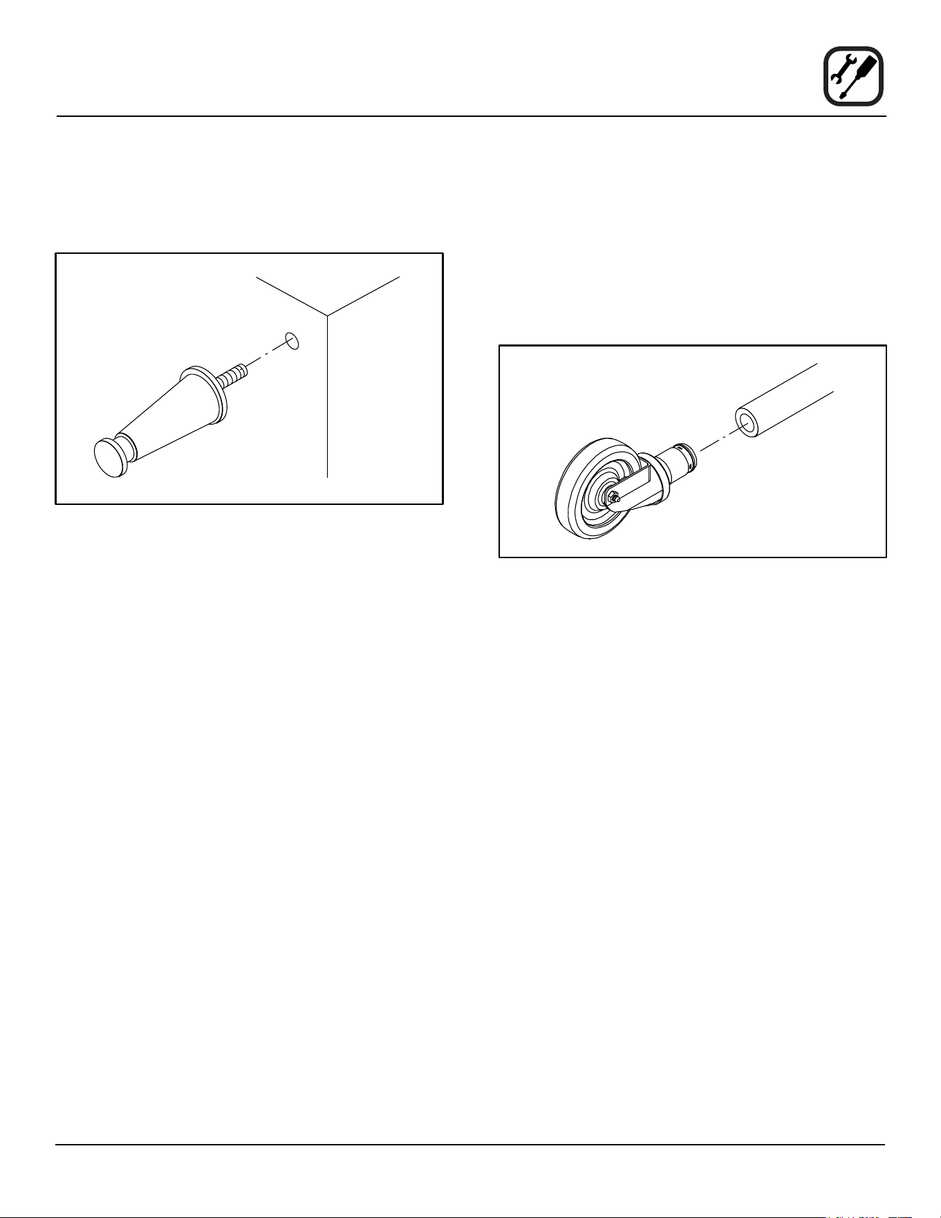
4” (10CM) LEG ATTACHMENT
1. Lay the oven on its side.
2. Screw one leg into each of the corner nuts.
Figure 5
CASTER INSTALLATION
NOTE: Casters are not supplied for the 4” (10cm) legs,
5-3/4” (15cm) or 7” (18cm) stands.
NOTE: Install the locking casters on the front of the oven.
Install the non-locking casters on the back of the
oven.
1. Insert the caster into the leg. Secure the caster to the
leg by tightening the locknut.
Figure 6
OVEN LEVELING
After assembly, the oven should be leveled and moved
to the operating location.
1. The oven can be leveled by adjusting the feet or cast-
ers located on the bottom of each leg.
8
Installation
Ventilation
On gas models the installation of a proper ventilation sys-
tem cannot be over emphasized. This system removes
unwanted vapors and products of combustion from the
operating area.
This oven may be vented using either:
• A mechanically driven, canopy type, exhaust hood,
or
• A direct ue arrangement.
U.S. and Canadian installations
Refer to your local ventilation codes. In the absence of
local codes, refer to the National ventilation code titled,
“Standard for the Installation of Equipment for the Remov-
al of Smoke and Grease Laden Vapors from Commercial
Cooking Equipment”, NFPA-96-Latest Edition.
Australia and General Export installations
Installation must conform with Local and National instal-
lation standards. Local installation codes and/or require-
ments may vary. If you have any questions regarding the
proper installation and/or operation of your Blodgett oven,
please contact your local distributor. If you do not have a
local distributor, please call the Blodgett Oven Company
at 0011-802-658-6600.
WARNING:
Failure to properly vent the oven can be haz-
ardous to the health of the operator and may
result in operational problems, unsatisfactory
baking and possible damage to the equip-
ment.
Damage sustained as a direct result of im-
proper ventilation will not be covered by the
manufacturer’s warranty.
CANOPY TYPE EXHAUST HOOD
A mechanically driven, canopy type exhaust hood is the
preferred method of ventilation.
The hood should be sized to completely cover the equip-
ment plus an overhang of at least 6” (15 cm) on all sides
not adjacent to a wall. The distance from the oor to the
lower edge of the hood should not exceed 7’ (2.1m).
The total makeup and exhaust air requirements for hood
capacity should be approximately 19 CFM for each oven
section.
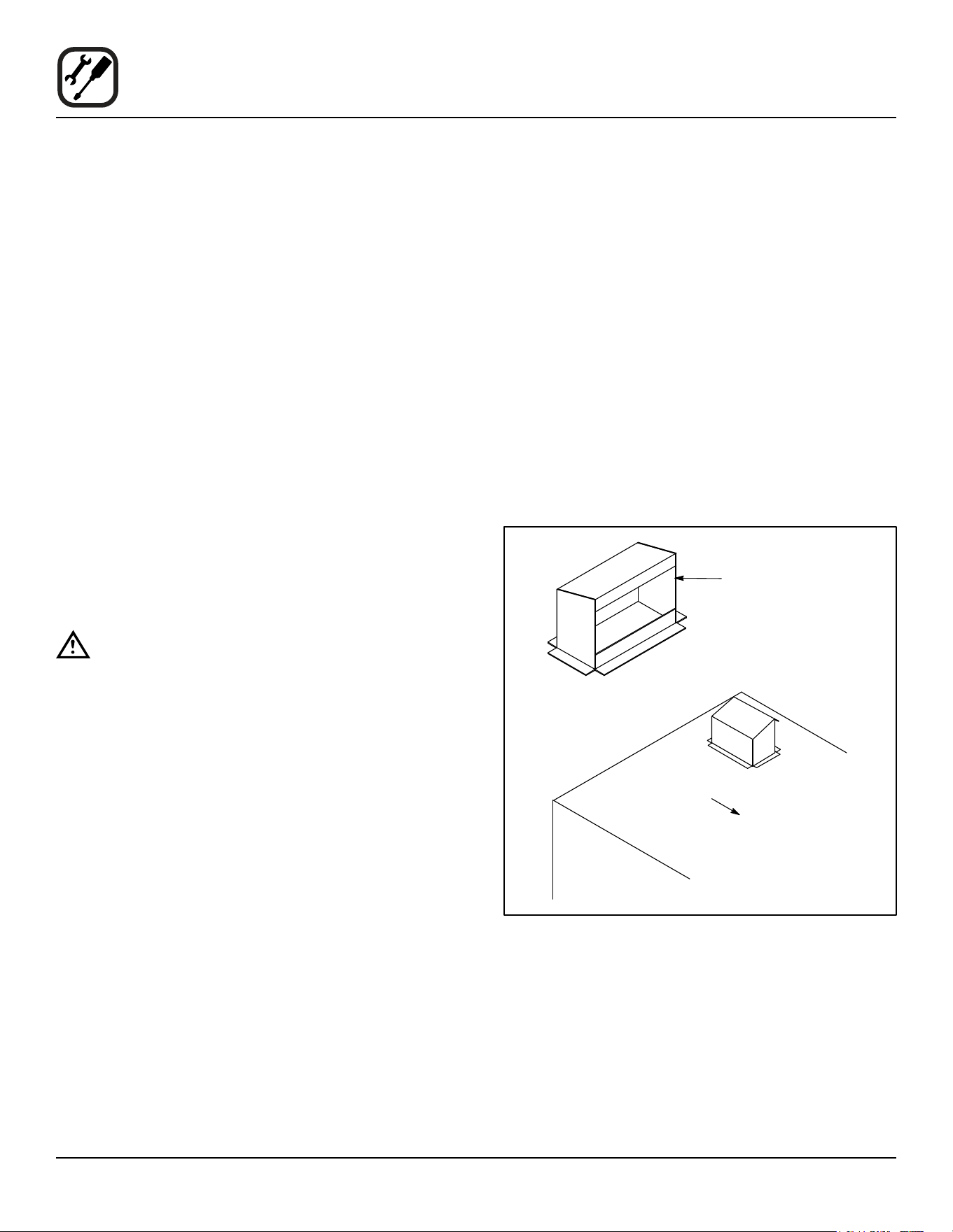
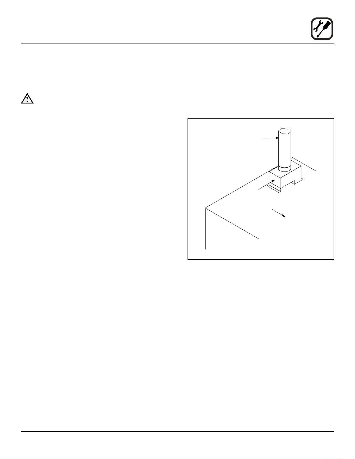
Installing the canopy hood draft diverter
Ovens ordered for hood venting are supplied with a draft
diverter. Install the draft diverter as follows:
1. Place the diverter over the ue connector with the
open area facing the right side of the oven.
2. Secure with the sheet metal screws provided.
Draft Diverter
Front of Oven
Figure 7
9
Installation
Ventilation
DIRECT FLUE ARRANGEMENT
When the installation of a mechanically driven exhaust
hood is impractical the oven may be vented by a direct
ue arrangement.
WARNING!!
It is essential that the direct ue be installed
as follows. Incorrect installation will result in
unsatisfactory baking and oven damage.
The ue must be class B or better with a diameter of 6”
(15 cm). The height of the ue should rise 6-8 ft (2-2.5 m)
above the roof of the building or any proximate structure.
Never direct vent the oven into a hood. The ue should
be capped with a UL Listed type vent cap to isolate the
unit from external environmental conditions.
The direct vent cannot replace air consumed and vented
by the oven. Provisions must be made to supply the room
with sucient make-up air. Total make-up air require-
ments for each oven section should be approximately 19
CFM per section. To increase the supply air entering the
room, a ventilation expert should be consulted.
Installing the draft hood
Ovens ordered for direct venting are supplied with a draft
hood. Install the draft hood as follows:
1. Place the draft hood over the ue connector.
2. Secure both ends with the sheet metal screws pro-
vided.
Draft Hood
Flue
Front of Oven
Figure 8
10
Installation
Utility Connections - Standards and Codes
THE INSTALLATION INSTRUCTIONS CONTAINED
HEREIN ARE FOR THE USE OF QUALIFIED INSTAL-
LATION AND SERVICE PERSONNEL ONLY. INSTAL-
LATION OR SERVICE BY OTHER THAN QUALIFIED
PERSONNEL MAY RESULT IN DAMAGE TO THE OVEN
AND/OR INJURY TO THE OPERATOR.
Qualied installation personnel are individuals, a rm,
a corporation, or a company which either in person or
through a representative are engaged in, and responsible
for:
• the installation or replacement of gas piping and the
connection, installation, repair or servicing of equip-
ment.
• the installation of electrical wiring from the electric
meter, main control box or service outlet to the elec-
tric appliance.
Qualied installation personnel must be experienced in
such work, familiar with all precautions required, and have
complied with all requirements of state or local authorities
having jurisdiction.
U.S. and Canadian installations
The installation must conform with local codes, or in the
absence of local codes, with the National Fuel Gas Code,
ANSI Z223.1/NFPA 54, or the Natural Gas and Propane
Installation Code, CSA B149.1, as applicable.
Installation must conform with local codes, or in the ab-
sence of local codes, with the National Electrical Code,
ANSI/NFPA 70-Latest Edition and/or Canadian National
Electric Code C22.1 as applicable.
Appliance is to be installed with backow prevention in
accordance with applicable federal, province and local
codes.
Australia and general export installations
Instllation must conform with Local and National instal-
lation standards. Local installation codes and/or require-
ments may vary. If you have any questions regarding the
proper installation and/or operation of your Blodgett oven,
please contact your local distributor. If you do not have a
local distributor, please call the Blodgett Oven Company
at 0011-802-658-6600.
11
Installation
Gas Connection
GAS PIPING
A properly sized gas supply system is essential for maxi-
mum oven performance. Piping should be sized to pro-
vide a supply of gas sucient to meet the maximum de-
mand of all appliances on the line without loss of pressure
at the equipment.
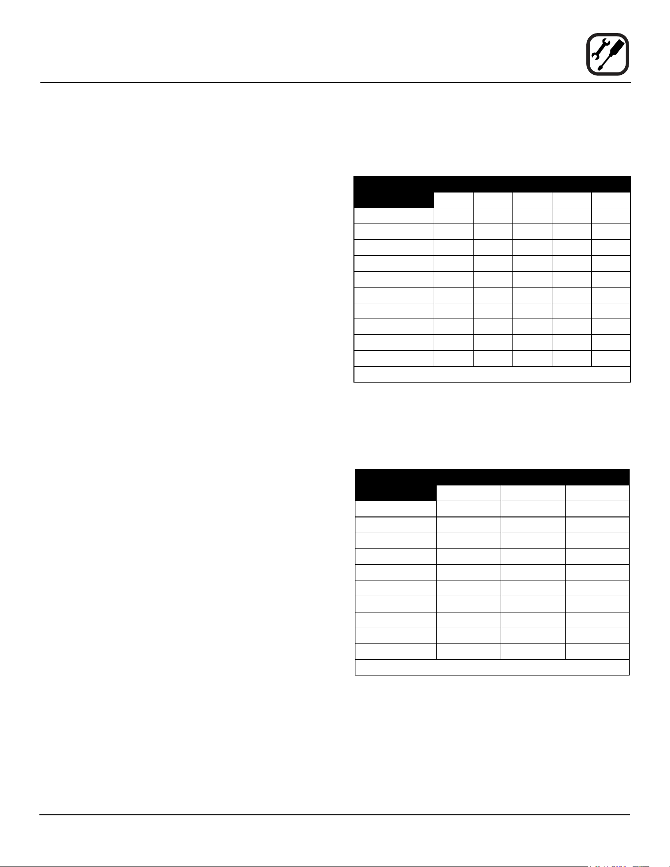
Example:
NOTE: BTU values in the following example are for natu-
ral gas.
You purchase a DFG-50 to add to your existing cook line.
1. Add the BTU rating of your current appliances.
Pitco Fryer 120,000 BTU
6 Burner Range 60,000 BTU
Deck Oven 50,000 BTU
Total 230,000 BTU
2. Add the BTU rating of the new oven to the total.
Previous Total 230,000 BTU
DFG-50 27,500 BTU
New Total 257,500 BTU
3. Measure the distance from the gas meter to the cook
line. This is the pipe length. Let’s say the pipe length
is 40’ (12.2 m) and the pipe size is 1” (2.54 cm).
4. Use the appropriate table to determine the total ca-
pacity of your current gas piping.
The total capacity for this example is 320,000 BTU. Since
the total required gas pressure, 257,500 BTU is less than
320,000 BTU, the current gas piping will not have to be
increased.
NOTE: The BTU capacities given in the tables are
for straight pipe lengths only. Any elbows or
other ttings will decrease pipe capacities.
Contact your local gas supplier if you have
any questions.
Maximum Capacity of Iron Pipe in Cubic Feet of
Natural Gas Per Hour
(Pressure drop of 0.5 Inch W.C.)
PIPE
LENGTH (FT)
NOMINAL SIZE, INCHES
3/4” 1” 1-1/4” 1-1/2” 2”
10 360 680 1400 2100 3950
20 250 465 950 1460 2750
30 200 375 770 1180 2200
40 170 320 660 990 1900
50 151 285 580 900 1680
60 138 260 530 810 1520
70 125 240 490 750 1400
80 118 220 460 690 1300
90 110 205 430 650 1220
100 103 195 400 620 1150
From the National Fuel Gas Code Part 10 Table 10-2
Maximum Capacity of Pipe in Thousands of
BTU/hr of Undiluted L.P. Gas at 11” W.C.
(Pressure drop of 0.5 Inch W.C.)
PIPE
LENGTH (FT)
OUTSIDE DIAMETER, INCHES
3/4” 1” 1-1/2”
10 608 1146 3525
20 418 788 2423
30 336 632 1946
40 287 541 1665
50 255 480 1476
60 231 435 1337
70 215 404 1241
80 198 372 1144
90 187 351 1079
100 175 330 1014
From the National Fuel Gas Code Part 10 Table 10-15
12
Installation
Gas Connection
PRESSURE REGULATION AND TESTING
DFG-50 ovens are rated at 27,500 BTU/Hr. (8.1 kW) (29
MJ) or 34,500 BTU/Hr. (10.1 kW) (36 MJ) per section.
Each oven has been adjusted at the factory to operate
with the type of gas specied on the rating plate.
INLET PRESSURE
Natural Propane
Min Max Min Max
W.C. 7.0 10.5 11.0 13.0
kPa 1.43 2.61 2.74 3.23
MANIFOLD PRESSURE
Natural Propane
W.C. 3.5 10.0
kPa .87 2.49
• Inlet Pressure - the pressure of the gas before it
reaches the oven.
• Manifold Pressure - the pressure of the gas as it
enters the main burner(s).
• Min - the minimum pressure recommended to oper-
ate the oven.
• Max - the maximum pressure at which the manufac-
turer warrants the oven’s operation.
Each oven is supplied with a regulator to maintain the
proper gas pressure. The regulator is essential to the
proper operation of the oven and should not be re-
moved. It is preset to provide the oven with 3.5” W.C.
(0.87 kPa) for natural gas and 10.5” W.C. (2.50 kPa) for
Propane at the manifold.
DO NOT INSTALL AN ADDITIONAL REGULATOR
WHERE THE OVEN CONNECTS TO THE GAS SUPPLY
UNLESS THE INLET PRESSURE IS ABOVE MAXIMUM.
Prior to connecting the oven, gas lines should be thor-
oughly purged of all metal lings, shavings, pipe dope,
and other debris. After connection, the oven should be
checked for correct gas pressure.
The oven and its individual shuto valve must be discon-
nected from the gas supply piping system during any
pressure testing of that system at test pressures in ex-
cess of 1/2 psig (3.45kPa).
The oven must be isolated from the gas supply piping
system by closing its individual manual shuto valve dur-
ing any pressure testing of the gas piping system at test
pressures equal or less than 1/2 psig (3.45kPa).
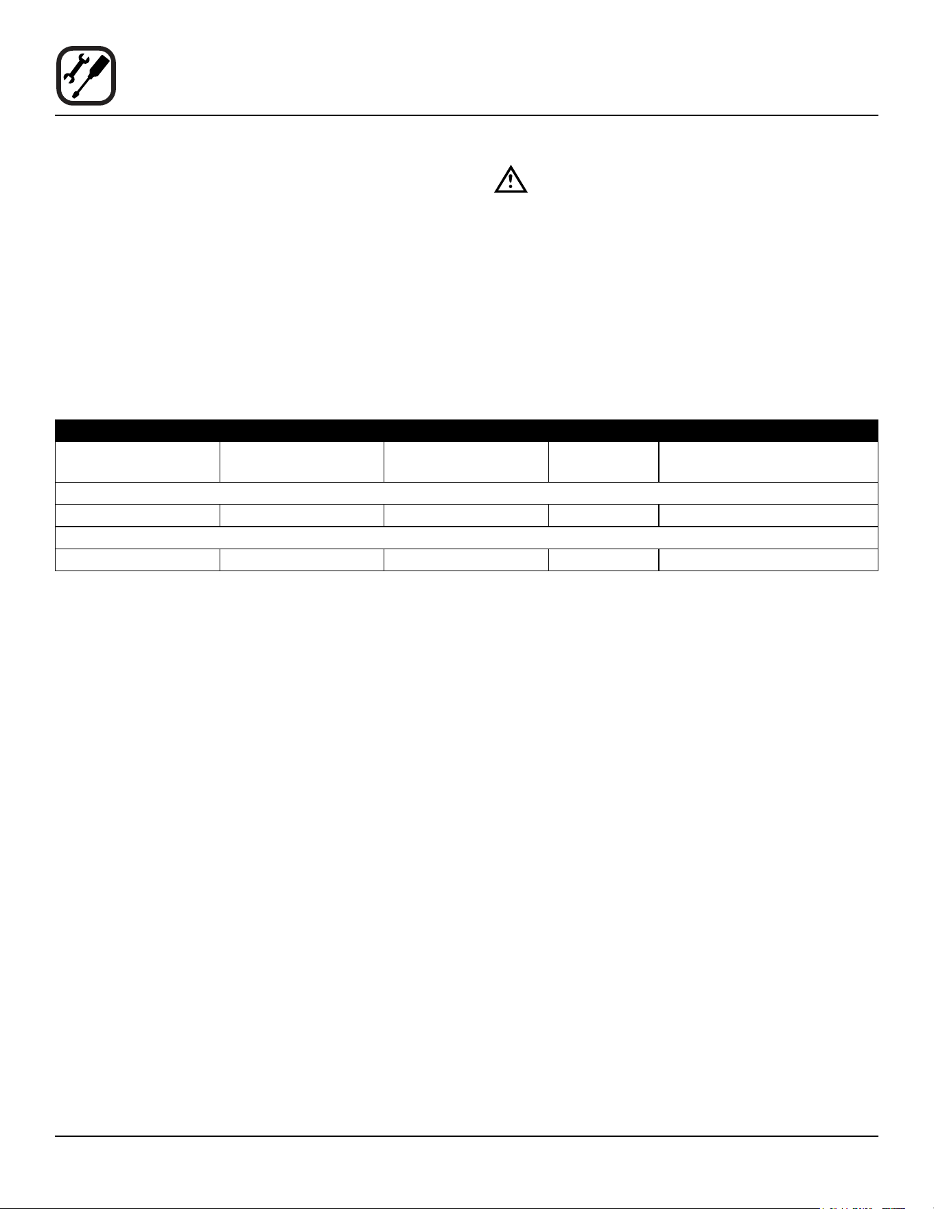
Gas Connection 4” (101.6 mm)
Gas Connection 2.75” (69.9 mm)
Figure 9

13
Installation
Gas Connection
GAS HOSE RESTRAINT
If the oven is mounted on casters, a commercial exible
connector with a minimum of 3/4” (1.9 cm) inside diam-
eter must be used along with a quick connect device.
The restraint, supplied with the oven, must be used to limit
the movement of the unit so that no strain is placed upon
the exible connector. With the restraint fully stretched the
connector should be easy to install and quick connect.
The restraint (ie: heavy gauge cable) should be 1,000 lb.
(453 kg) test load and should be attached without damag-
ing the building. DO NOT use the gas piping or electrical
conduit for the attachment of the permanent end of the
restraint! Use anchor bolts in concrete or cement block.
On wooden walls, drive hi test wood lag screws into the
studs of the wall.
1. A 3/8” diameter hole has been provided on the bottom
of the oven just below the gas inlet. the hole is sized
to accept a clip-on restraining cable supplied with the
ex hose.
WARNING!!
If the restraint is disconnected for any rea-
son it must be reconnected when the oven is
returned to its original position.
U.S. and Canadian installations
The connector must comply with the Standard for Connec-
tors for Movable Gas Appliances, ANSI Z21.69 or Con-
nectors For Moveable Gas Appliances CAN/CGA-6.16-
M87 and a quick disconnect device that complies with the
Standard for Quick-Disconnect Devices for Use With Gas
Fuel, ANSI Z21.41 or Quick Disconnect For Use With Gas
Fuel CAN 1-6.9. Adequate means must be provided to
limit the movement of the appliance without depending
on the connection and the quick disconnect device or its
associated piping.
Australia and General Export installations
The restraint and quick connect must conform with Lo-
cal and National installation standards. Local installation
codes and/or requirements may vary. If you have any
questions regarding the proper installation and/or opera-
tion of your Blodgett oven, please contact your local dis-
tributor. If you do not have a local distributor, please call
the Blodgett Oven Company at 0011-802-658-6600.
14
Installation
Electrical Connection
Wiring diagrams are located in the motor access panel
and on the back of the oven.
This oven is supplied for connection to 115 volt grounded
circuits. The electric motor, indicator lights and related
switches are connected through the 6’ electric supply cord
found at the rear of the oven.
The Blodgett Oven Company cannot assume respon-
sibility for loss or damage suered as a result of im-
proper installation.
WARNING!!
This appliance is equipped with three prong
grounding type plug for your protection
against shock hazard and should be plugged
directly into a properly grounded three prong
receptacle. DO NOT cut or remove the ground-
ing prong from this plug.
ELECTRICAL SPECIFICATIONS
Hz Volts Phase Amps Electrical Connection
(minimum size)
U.S. and Canadian Installations
60 115 1 5 Cord set provided
Australia and General Export Installations
50 220-240 1 3 Size per local code

15
Installation
Initial Startup
The following is a check-list to be completed by qualied
technician prior to turning on the appliance for the rst
time.
1. Open the manual shut-o valve at the rear of the
oven.
2. Remove the control panel and combustion covers.
3. Verify the combination valve’s manual shut-o is in
the on position.
4. Turn the selector switch to Cook, and the thermostat
to 500ºF (260ºC).
With the main burner on, check the following.
• Verify there are no gas leaks, by checking all gas
connections with a soapy water solution.
• Verify that the inlet pressure is correct. The inlet
pressure can be checked at the pressure tap located
on the combination valve’s inlet side.
• Verify that the manifold pressure is correct. The
manifold pressure can be checked at the pressure
tap located on the combination valve’s outlet side.
• If the above pressure readings are set to the recom-
mended pressure requirements, allow the oven to
burn-o for 2 hours. If the pressure readings are not
set correctly, turn o the oven and readjust accord-
ingly.
WARNING
The break in procedure burns o excess
oils present in the metals during fabrication.
Smoke may be produced. Proper ventilation is
required.
ADJUSTMENTS ASSOCIATED WITH INITIAL INSTAL-
LATION
Each oven, and its component parts, have been thorough-
ly tested and inspected prior to shipment. However, it is
often necessary to further test or adjust the oven as part
of a normal and proper installation. These adjustments
are the responsibility of the installer, or dealer. Since
these adjustments are not considered defects in mate-
rial or workmanship, they are not covered by the Original
Equipment Warranty. They include, but are not limited to:
• calibration of the thermostat
• adjustment of the doors
• burner adjustments
• leveling
• testing of gas pressure
• tightening of fasteners.
No installation should be considered complete without
proper inspection, and if necessary, adjustment by quali-
ed installation or service personnel.

16
Operation
Safety Information
The information contained in this section is provided for
the use of qualied operating personnel. Qualied operat-
ing personnel are those who have carefully read the in-
formation contained in this manual, are familiar with the
functions of the oven and/or have had previous experi-
ence with the operation of the equipment described. Ad-
herence to the procedures recommended herein will as-
sure the achievement of optimum performance and long,
trouble-free service.
Please take the time to read the following safety and op-
erating instructions. They are the key to the successful
operation of your Blodgett oven.
SAFETY TIPS
For your safety read before operating
What to do if you smell gas:
• DO NOT try to light any appliance.
• DO NOT touch any electrical switches.
• Use an exterior phone to call your gas supplier im-
mediately.
• If you cannot reach your gas supplier, call the re
department.
What to do in the event of a power failure:
• Turn all switches to o.
• DO NOT attempt to operate the oven until the power
is restored.
NOTE: In the event of a shut-down of any kind, allow a
ve (5) minute shut o period before attempting to
restart the oven.
General safety tips:
• DO NOT use tools to turn o the gas control. If the
gas cannot be turned o manually do not try to re-
pair it. Call a qualied service technician.
• If the oven needs to be moved for any reason, the
gas must be turned o and disconnected from the
unit before removing the restraint cable. Reconnect
the restraint after the oven has been returned to its
original location.
• DO NOT remove the control panel cover unless the
oven is unplugged.
17
Operation
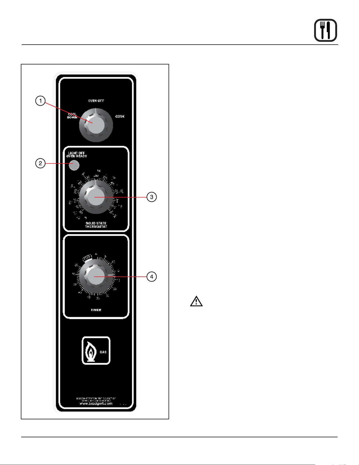
Figure 10
Solid State Manual Control
CONTROL DESCRIPTION
1. SELECTOR SWITCH - controls power to the oven for
cook or cool down.
2. OVEN READY LIGHT - when lit indicates burner op-
eration. When the light goes out the oven has reached
operating temperature.
3. SOLID STATE THERMOSTAT - allows either 8 pre-
set temperatures to be selected in accordance with
customer requirements, or an innite selection of
temperatures from 200-500ºF (95-260ºC). (innite
control shown)
4. TIMER - activates an electric buzzer that sounds
when the cook time expires.
OPERATION
1. Turn the SELECTOR Switch (1) to COOK. The blower
and control compartment cooling fan operate and are
controlled automatically by the action of the doors.
2. Set the SOLID STATE THERMOSTAT (3) to the de-
sired setting or temperature.
3. Preheat until the OVEN READY LIGHT (2) goes out.
4. Load product into the oven. Determine cook time and
set the TIMER (4).
5. When the buzzer sounds, remove the product from
the oven. Turn the TIMER knob (4) to OFF to silence
the buzzer.
6. Turn the SELECTOR Switch (1) to OVEN OFF.
WARNING!!
A complete ve minute shutdown must be
observed before the oven is relighted.
18
Operation
Solid State Digital Control
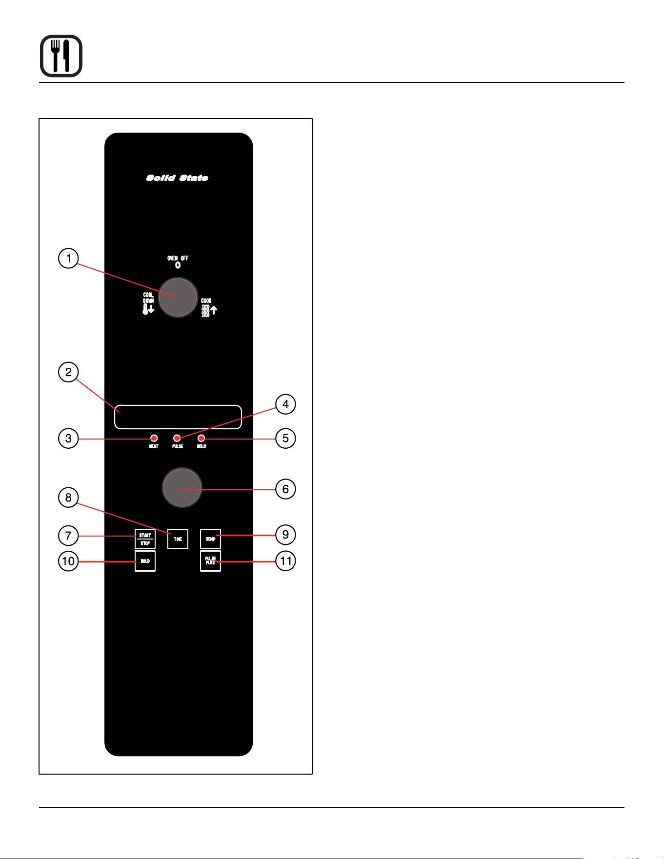
Figure 11
CONTROL DESCRIPTION
1. SELECTOR SWITCH - turns power to the oven on or
o. Allows selection of Cook or Cool Down Modes.
2. DISPLAY - displays time or temperature and other in-
formation related to oven function.
3. HEAT LAMP - lights when heater is on.
4. PULSE LAMP - lights when Pulsed Fan Mode is
turned on.
5. HOLD LAMP - lights when Hold Mode is turned on.
6. DIAL - used to enter set points in display
7. START/STOP KEY - starts or stops the timer.
8. TIME KEY - used to show time in the display.
9. TEMP KEY - used to show set temperature in the dis-
play.
NOTE: Actual temperature is shown while the TEMP
key is held down.
10. HOLD KEY - turns Hold Mode on or o.
11. PULSE KEY - turns Pulse Mode on or o.
PROGRAMMING
To set the cook temperature:
1. Press TEMP (9) key.
2. Rotate dial (6) to enter temperature.
To set the cook time:
1. Press TIME (8) key.
2. Rotate the dial (6) to enter time.
NOTE: Time is entered in hours : minutes or minutes
: seconds.
To set the hold time:
1. Press HOLD key (10) to turn hold mode on.
NOTE: HOLD light is on.
2. Rotate dial (6) to enter the hold temperature.
3. Press START/STOP key (7)
To set the pulse time:
1. Press PULSE KEY (11) to turn pulse mode on.
NOTE: Pulse light is on.
2. Rotate DIAL (6) to enter the pulse time. Pulse time is
a portion of the pre-set cook time.

19
Operation
Solid State Digital Control
OPERATION
Cook Only:
1. Turn SELECTOR switch (1) to the desired position.
2. Enter the cook time and temperature.
3. Load product into oven.
NOTE: The display reads LOAD when the oven is
near the set temperature.
4. Press the START/STOP key (7). The timer begins to
count down.
5. When the cook timer reaches 00:00 the buzzer
sounds and the display reads DONE.
6. Press the START/STOP key (7) to silence the buzzer.
7. Remove the product.
Cook with Hold:
NOTE: HOLD light is on when hold mode is on and o
when hold mode is o.
1. Turn SELECTOR switch (1) to the desired position.
2. Enter the cook time and temperature.
3. Press the HOLD key (10). Enter the hold temperature.
4. Load product into oven.
NOTE: The display reads LOAD when the oven is
near the set temperature.
5. Push the START/STOP (7) key. Timer begins to count
down.
6. When the cook timer reaches 00:00 the buzzer sounds
and the display reads DONE. The buzzer turns o af-
ter a few seconds. The display reads HOLD until the
oven reaches the hold temperature. Then the timer
begins to count up.
7. Push the START/STOP key (7) to stop timer.
8. Remove the product.
9. Push HOLD (10) key to turn o hold mode.
Cook with Pulse:
NOTE: PULSE light is on when pulse mode is on and o
when pulse mode is o.
1. Turn the SELECTOR SWITCH (1) to the desired posi-
tion.
2. Enter cook time and cook temperature.
3. Press PULSE KEY (11). Enter the pulse time.
NOTE: Pulse time is a portion of the cook time and
does not increase the previously entered
cook time.
4. Load product into oven.
NOTE: The display reads LOAD when the oven is
near the set temperature.
5. Push START/STOP KEY (7). The timer begins to
count down the cook time. The oven will be in pulse
mode for the set pulse time. Once the set time has
expired, the unit automatically switches to cook mode
and continues counting down.
6. When the cook timer reaches 00:00 the buzzer
sounds and the display reads DONE.
7. Push the START/STOP KEY (7) to turn the buzzer o.
8. Remove the product.
WARNING!!
A complete ve minute shutdown must be
observed before the oven is relighted.
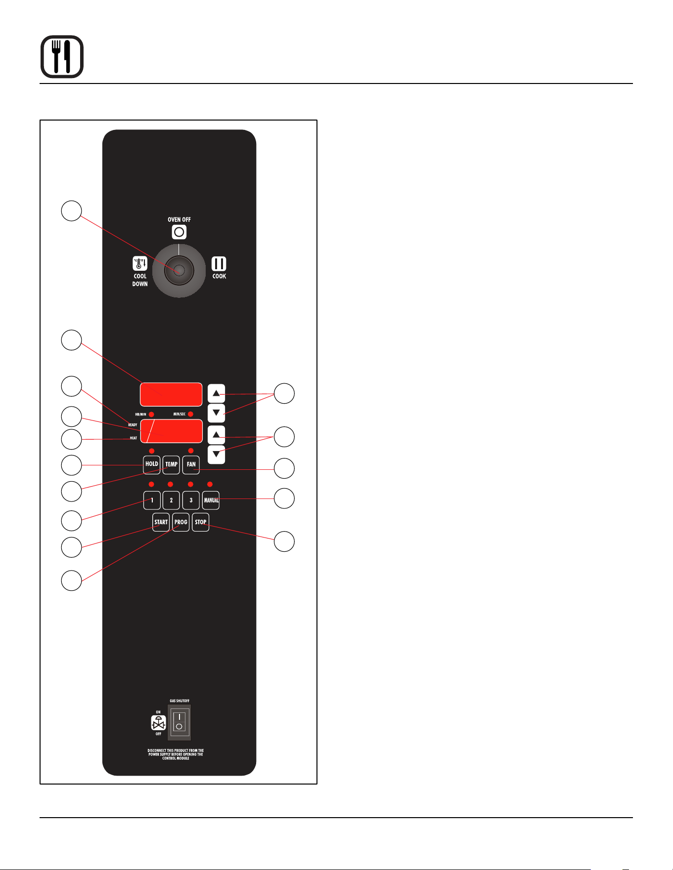
20
Operation
CH-Pro3 (Solid State Programmable Digital Control)
COMPONENT DESCRIPTION
1. SELECTOR SWITCH - turns power to the oven on or
o. Allows selection of cook or cool down modes and
fan speed (if applicable).
2. TIME DISPLAY - gives cook time.
3. TIME ARROW KEYS - press to enter cook and/or
pulse times.
4. READY INDICATOR - when lit indicates the oven has
reached the setpoint temperature and product may
be loaded.
5. TEMPERATURE DISPLAY - gives cook and hold
temperatures.
6. HEAT INDICATOR - when lit indicates the oven is
heating.
7. TEMPERATURE ARROW KEYS - press to enter
cook and hold temperatures.
8. HOLD KEY - turns hold mode on or o.
9. TEMP KEY - press to display actual oven tempera-
ture.
10. FAN KEY - turns pulse mode on or o. The LED
above the fan key is always on.
11. PRODUCT KEYS - three programmable keys.
12. MANUAL PRODUCT KEY - default product key used
for manual operation.
13. START KEY - press to begin a cook cycle.
14. PROGRAM KEY - press to enter programming mode
and save programmed settings.
15. STOP KEY - press to silence audible alarms and can-
cel cook cycles.
Solid State
7
10
12
15
3
1
2
4
5
6
8
9
11
13
14
Figure 12

21
Operation
CH-Pro3 (Solid State Programmable Digital Control)
MANUAL OPERATION
NOTE: Press the arrow keys to change the cook time and
temperature at any point duringmanual operation.
Cook Only:
1. Turn the SELECTOR SWITCH (1) to the desired posi-
tion.
2. Press the MANUAL PRODUCT KEY (12). The manu-
al and fan key LEDs light.
3. Press the TIME ARROW KEYS (3) to enter the cook
time.
4. Press the TEMPERATURE ARROW KEYS (7) to en-
ter the cook temperature.
5. The READY INDICATOR (4) lights when the oven is
at the set temperature. Load product into the oven.
6. Press the START KEY (13). The TIME DISPLAY (2)
counts down. The manual key LED ashes.
7. When the cook time expires the LEDs and both dis-
plays ash and an audible alarm sounds. Press the
STOP KEY (15) to silence the alarm.
8. Remove the product.
Cook with Hold:
1. Turn the SELECTOR SWITCH (1) to the desired posi-
tion.
2. Press the MANUAL PRODUCT KEY (12). The manu-
al and fan key LEDs light.
3. Press the TIME ARROW KEYS (3) to enter the cook
time.
4. Press the TEMPERATURE ARROW KEYS (7) to en-
ter the cook temperature.
5. Press and hold the HOLD KEY (8). At the same time
use the TEMPERATURE ARROW KEYS (7) to enter
the hold temperature. The hold key LED lights.
6. The READY INDICATOR (4) lights when the oven is
at the set temperature. Load product into the oven.
7. Press the START KEY (13). The TIME DISPLAY (2)
counts down. The manual key LED ashes.
8. When the cook time expires both displays ash and
an audible alarm sounds for several seconds then
self cancels. The hold key LED ashes. The time dis-
play begins to count up while the oven cools to the
hold temperature. When the oven reaches the hold
temperature the time display resets to 00:00 then be-
gins to count up the hold time. The fan cycles with
heat demand in the hold mode.
9. Press the STOP KEY (15) to stop the timer.
10. Remove the product.
11. Push the HOLD KEY (8) to turn o hold mode.
Cook with Pulse:
1. Turn the SELECTOR SWITCH (1) to the desired posi-
tion.
2. Press the MANUAL PRODUCT KEY (12). The manu-
al and fan key LEDs light.
3. Press the TEMPERATURE ARROW KEYS (7) to en-
ter the cook temperature.
4. Press the FAN KEY (10). The fan key LED ashes.
Use the TIME ARROW KEYS (3) to enter the pulse
time.
5. The READY INDICATOR (4) lights when the oven is
at the set temperature. Load product into the oven.
6. Press the START KEY (13). The manual key LED
ashes. The TIME DISPLAY (2) counts down. The fan
cycles on for 30 seconds then o for 30 seconds until
the set pulse time has expired.
7. When the pulse time expires both displays ash and
an audible alarm sounds. Press the STOP KEY (15)
to silence the alarm.
8. Remove the product.
Oven Shut Down:
1. Turn the SELECTOR SWITCH (1) to OVEN OFF.

22
Operation
CH-Pro3 (Solid State Programmable Digital Control)
PROGRAMMING THE MANUAL KEY DEFAULT
1. Turn the SELECTOR SWITCH (1) to the desired posi-
tion.
2. Press the MANUAL KEY (12). The manual and fan
key LEDs light.
3. Press the PROGRAM KEY (14).
4. Press the TIME ARROW KEYS (3) to enter the cook
time.
5. Press the TEMPERATURE ARROW KEYS (7) to en-
ter the cook temperature.
6. For Cook and Hold - Press and hold the HOLD KEY
(8). At the same time use the TEMPERATURE AR-
ROW KEYS (7) to enter the hold temperature. The
hold key LED lights.
For Cook with Pulse - Press the FAN KEY (10). Use
the TIME ARROW KEYS (3) to enter the pulse time.
The fan key LED ashes.
7. Press the PROGRAM KEY (14) to save the program
settings.
MANUAL KEY DEFAULT OPERATION
1. Turn the SELECTOR SWITCH (1) to the desired posi-
tion.
2. Press the MANUAL KEY (12). The applicable LEDs
light.
3. Press the START KEY (13). The TIME DISPLAY (2)
counts down. The manual key LED ashes.
NOTE: In Cook with Pulse the fan LED ashes.
NOTE: Press the arrow keys to change the cook time
and temperature at any point during manual
key operation.
4. When the cook time expires the applicable LEDs and
both displays ash and an audible alarm sounds.
5. Press the STOP KEY (15) to silence the alarm.
NOTE: In Cook & Hold the alarm self cancels. The
oven cools to the hold temperature and the
time display counts up.
6. Remove the product.
7. Turn the SELECTOR SWITCH (1) to OFF to shut
down the oven.
PROGRAMMING THE PRODUCT KEYS
1. Turn the SELECTOR SWITCH (1) to the desired posi-
tion.
2. Press the desired PRODUCT KEY (11). The product
and fan key LEDs light.
3. Press and hold the PROGRAM KEY (14) until the cor-
responding LED ashes, approximately ve seconds.
4. Press the TIME ARROW KEYS (3) to enter the cook
time.
5. Press the TEMPERATURE ARROW KEYS (7) to en-
ter the cook temperature.
6. For Cook and Hold - Press and hold the HOLD KEY
(8). At the same time use the TEMPERATURE AR-
ROW KEYS (7) to enter the hold temperature. The
hold key LED lights.
For Cook with Pulse - Press the FAN KEY (10). Use
the TIME ARROW KEYS (3) to enter the pulse time.
The fan key LED ashes.
7. Press the PROGRAM KEY (14) to save the program
settings.
PRODUCT KEY OPERATION
1. Turn the SELECTOR SWITCH (1) to the desired posi-
tion.
2. Press the desired PRODUCT KEY (11). The appli-
cable LEDs light.
3. Press the START KEY (13). The TIME DISPLAY (2)
counts down. The product key LED ashes.
NOTE: In Cook with Pulse the fan LED ashes.
4. When the cook or pulse time expires the applicable
LEDs and both displays ash and an audible alarm
sounds.
5. Press the STOP KEY (15) to silence the alarm.
NOTE: In Cook and Hold the alarm self cancels. The
oven cools to the hold temperature and the
time display counts up.
6. Remove the product.
7. Turn the SELECTOR SWITCH (1) to OFF to shut
down the oven.
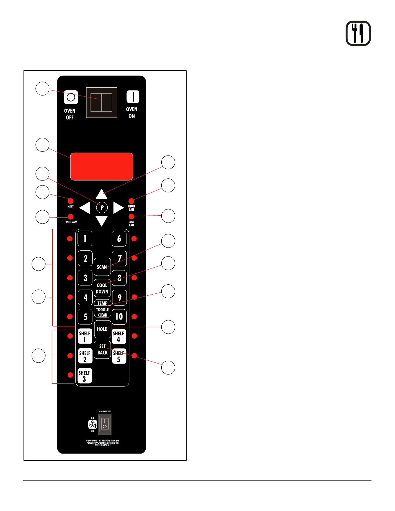
23
Operation
Blodgett IQ2™ Vision Control
1
2
3
5
6
4
7
8
9
10
16
12
11
13
15
14
Figure 13
COMPONENT DESCRIPTION
1. OVEN POWER SWITCH - controls power to the oven.
2. DISPLAY - displays temperature and other controller
related information.
3. PROGRAM KEY - press to enter the programming
mode.
4. PROGRAM ARROW KEYS - use to move through
programming menus and options
5. HEAT LED - when lit indicates the control is calling
for heat.
6. PROG LED - when lit indicates the controller is in the
programming mode.
7. HIGH FAN LED - when lit indicates the fan is running
at high speed.
8. LOW FAN LED - when lit indicates the fan is running
at low speed.
9. SCAN KEY - Press to view time remaining on multiple
cook cycles and to review recipe programming.
10. COOL DOWN KEY - press to enter the cool down
mode.
11. TEMP/TOGGLE/CLEAR KEY - press during pro-
gramming to toggle options.
12. HOLD KEY - press to enter hold mode.
13. SET BACK KEY -
14. PRODUCT KEYS (1-10) - assigns a key to a pro-
grammed recipe and begins a programmed cooking
process. Also used to enter numeric values in the pro-
gramming mode.
15. PRODUCT LEDS - when lit indicate which product
keys are currently in use or programmed for the cur-
rent oven temperature and fan speed.
16. SHELF KEYS (1-5) - assigns a shelf key.
24
Operation
Blodgett IQ2™ Vision Control
OVEN OPERATION
Oven Startup:
1. Toggle the POWER SWITCH (1) to ON. The display
gives the software revision level. The oven preheats
to the lowest programmed rst stage temperature.
The LEDS (15) for all products with the same rst
stage temperature light.
Single Product Cooking Procedure:
NOTE: If the led next to the desired product key is lit skip
step 1.
1. Press the desired PRODUCT KEY (14). The oven
preheats to the rst stage temperature for the select-
ed product. When the oven reaches 10° of the pre-
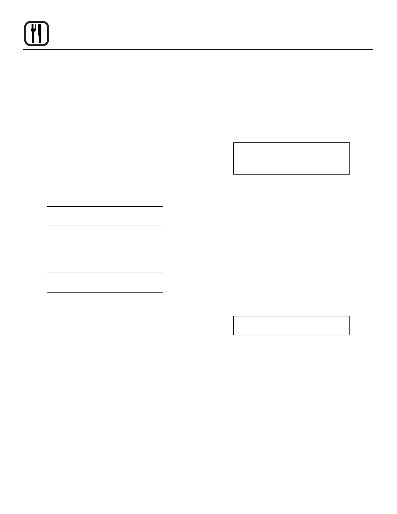
heat temperature an alarm sounds and the DISPLAY
(2) read:
LOAD
2. Load the product into the oven. Press the desired
PRODUCT KEY (14).
3. If the shelf timing function is toggled to the on po-
sition for that product key, the DISPLAY (2) reads:
PICK SHLF
Press a SHELF KEY (16) to assign the product to that
shelf and start the cook cycle. Within ve seconds,
the DISPLAY (2) scrolls the product name and shelf
number and counts down the remaining cook time.
If the shelf timing function is toggled to the o
position for that product, pressing the product key
will start the cook cycle. The DISPLAY (2) scrolls the
product name and counts down the remaining cook
time.
NOTE: If the selected product has a cook time of
greater than 59:59 the DISPLAY (2) switches
to hours:minutes.
NOTE: If the selected product is a single stage reci-
pe the LEDS for all single stage products with
the same cook temperature and fan speed
will light. If the selected product is a multiple
stage recipe no other product LEDS will light.
NOTE: Press and hold the selected product key for
three seconds to cancel the cook cycle for
normal operation. To cancel the cook cycle
when using shelf timing, press and hold the
corresponding SHELF KEY (16) for 3 sec-
onds.
4. When the cook time expires an alarm sounds and the
DISPLAY (2) reads:
DONE
Product name
5. Press the selected product key to silence the alarm.
Remove the product. If shelf timing is used, press the
ashing SHELF KEY (16) to silence the alarm.
Multiple Batch Cooking Procedure:
This procedure is for single stage recipes with the same
cook temperature and fan speed only.
NOTE: If the led next to the rst desired product key is lit
skip step 1.
1. Press the rst desired PRODUCT KEY (14). The
LEDS for all recipes with the same cook temperature
and fan speed will light.
The oven preheats to the cook temperature for the
selected product. When the oven reaches +10° of the
preheat temperature an alarm sounds and the DIS-
PLAY (2) reads:
LOAD
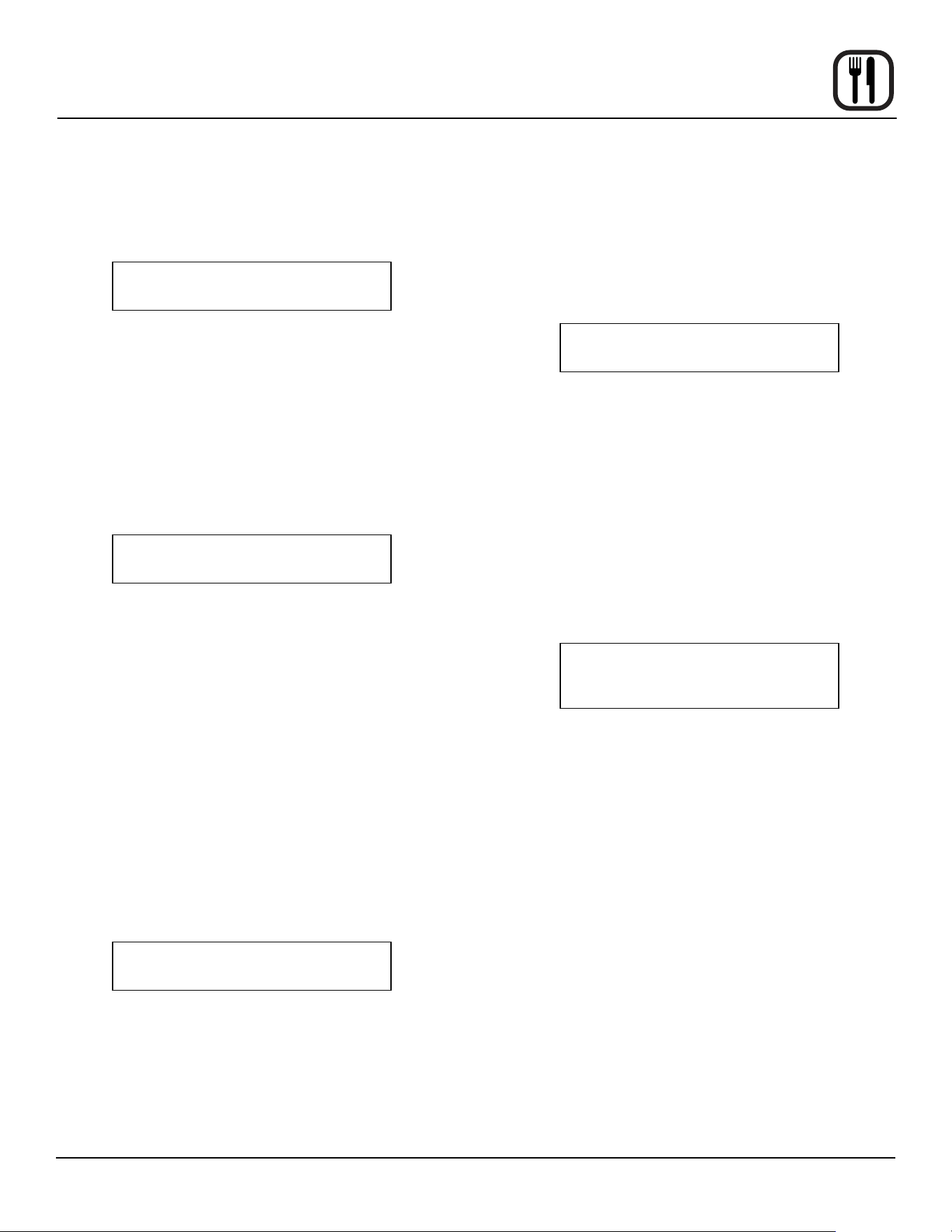
25
Operation
Blodgett IQ2™ Vision Control
2. Load the product into the oven. Press the desired
PRODUCT KEY (14).
If the shelf timing function is toggled to the on po-
sition for that product key, the DISPLAY (2) reads
PICK SHLF
Press a SHELF KEY (16) to assign the product to that
shelf and start the cook cycle. Within ve seconds,
the DISPLAY (2) scrolls the product name and shelf
number and counts down the remaining cook time.
If the shelf timing function is toggled to the o position
for that product, pressing the product key will start
the cook cycle. The DISPLAY (2) scrolls the product
name and counts down the remaining cook time.
3. Load the second product. Press the desired PROD-
UCT KEY (14). the DISPLAY (2) reads
PICK SHLF
Press a SHELF KEY (16) to assign the product to that
shelf and start the cook cycle for product two.
NOTE: Only products with lighted LEDS may be se-
lected.
Repeat step 3 for additional products.
4. The DISPLAY (2) scrolls the product name and counts
down the remaining cook time for the product with the
least time remaining.
NOTE: To view the remaining cook time for the other
products press and hold the SCAN KEY (9).
The display cycles through the remaining
cook times for each product. Only the led for
the product with the cook time displayed will
be lit.
5. When a cook time expires an alarm sounds. The dis-
play reads
DONE
The led for the nished product lights. All other LEDS
are dark.
6. Press the SHELF KEY (16) for the nished product
to silence the alarm. Remove the product. Close the
oven door. The DISPLAY (2) scrolls the product name
and counts down the remaining cook time for the
product with the least time remaining.
7. When the cook time expires an alarm sounds and the
display reads:
DONE
8. Press the SHELF KEY (16) to silence the alarm. Re-
move the product.
Oven Cool Down:
1. Close the oven door. Press the COOL DOWN KEY
(10).
NOTE: Cool down cannot be activated with the oven
door open. Once the cool down cycle has be-
gun the doors may be opened to speed the
cooling process.
To Review Repipe Programming:
1. Press the SCAN KEY (9). The display reads:
RECIPE REVIEW
Select Product
The LEDs (15) for all previously programmed product
keys light. Press the PRODUCT KEY (14) you wish
to review. The display gives the recipe cook time for
stage 1. Use the PROGRAM ARROW KEYS (4) to
scroll through the recipe programming for the select-
ed product key.
2. The control will exit recipe review after 30 seconds if
no key is pressed.
26
Operation
Blodgett IQ2™ Vision Control
PRODUCT KEY PROGRAMMING
To enter the product programming mode
1. Press and hold the PROGRAM KEY (3). The DIS-
PLAY (2) reads:
Prod Cnt
Programming
Use the PROGRAM ARROW KEYS (4) to highlight
Programming. Press the PROGRAM KEY (3) to se-
lect. The display reads:
ENTER CODE
Use the PRODUCT KEYS (14) to enter the program-
ming access code 1724. Press the PROGRAM KEY
(3). The display reads:
RECIPE
Press the PROGRAM KEY (3). All of the product
LEDSs will light and the display reads:
Select Product
to Program
To select the product to program
2. Press the desired product key. The display reads:
All
Name
With All highlighted, press the PROGRAM KEY (3).
The display reads:
Product Name
AAA
The rst alphabetical listing in the product name li-
brary appears.
3. To change the product name, use the PROGRAM
ARROW KEYS (4) to scroll through the product name
library. When the desired product name is highlighted,
press the PROGRAM KEY (3) to select.
To program the product
4. The display reads:
Shelf Cook
AAA
Denition: Shelf cook enables the operator to
reference product to one of the ve shelf posi-
tions in the oven. At the end of a shelf cook-
ing cycle the oven will display the name of the
product and the shelf number that is ready to
be pulled. Shelf cooking is not available for
multi-stage recipes.
Use non shelf cooking when you do not need
to reference product to one of the ve shelf
positions in the oven. Non shelf cooking may
be used for single stage recipes and MUST be
use for multi-stage recipes.
Use the PROGRAM ARROW KEYS (4) to select
either YES (for shelf cooking) or NO (for non shelf
cooking). Press the PROGRAM KEY (3).
5. The display reads:
Stage 1 Time
XX:XX
Use the PRODUCT KEYS (14) to enter the desired
cook time. Press the PROGRAM KEY (3).
6. The display reads:
Stage 1 Temp
XXXF (or C)
Use the PRODUCT KEYS (14) to enter the desired
cook temperature. Press the PROGRAM KEY (3).
27
Operation
Blodgett IQ2™ Vision Control
7. The display reads:
Stage 1 Timing
XX:XX
Denition: There are 3 options for timing
mode when shelf cooking: Straight, Flex and
Sensitivity. Straight has no time adjustment.
Flex adjusts the cook time to compensate for
any dierence between the setpoint and actual
temperature. Sensitivity enables a product key
to have a ex adjustment for each of the ve
shelves. Sensitivity values are set in the man-
ager level programming.
NOTE: Sensitivity is only available when using shelf
cooking.
Use the PROGRAM ARROW KEYS (4) to select the
desired timing mode. Press the PROGRAM KEY (3).
8. The display reads:
Stage 1 Fan Speed
XX
Use the PROGRAM ARROW KEYS (4) to select ei-
ther HIGH or LOW fan speed. Press the PROGRAM
KEY (3).
9. The display reads:
Stage 1 Fan Cyc
XXX
Denition: There are 3 options for fan cycle
time: Pulse, Heat and Full. Pulse allows the fan
to turn on and o as programmed. Heat allows
the fan to operate with heat only. Full provides
continuous fan operation when door is closed.
Use the PROGRAM ARROW KEYS (4) to select the
fan cycle. If heat or full are selected skip to step 10. If
pulse is selected the display reads:
Stage 1 Fan On
XX:XX
Use the PRODUCT KEYS (14) to enter the desired
length of the time the fan should be on in the pulse
cycle. Press PROGRAM KEY (3). The display reads:
Stage 1 Fan O
XX:XX
Use the PRODUCT KEYS (14) to enter the desired
length of the time the fan should be o in the pulse
cycle. Press the PROGRAM KEY (3).
10. If you are programming a product using shelf cooking
skip to step 11.
If you are programming a product that does not use
shelf cooking the display reads:
Stage 2 Time
XX:XX
Repeat steps 5 through 10 for each remaining stage.
If you are programming a single stage recipe without
shelf cooking enter at time of 00:00 for stage 2.
11. The display reads:
Alarm 1 Time
XX:XX
Denition: If you would like the alarm to sound
prior to the completion of the cook cycle you
may program it here. The alarm time counts
up from the beginning of the cook cycle. For
example, if you want an alarm 9 minutes into
the cook cycle, program the alarm time at 9:00.
Use the PRODUCT KEYS (14) to enter the time for
the rst alarm to sound. If 00:00 is entered for an
alarm time, skip to step 12.
Press the PROGRAM KEY (3). If a time other than
00:00 is entered the display reads:
28
Operation
Blodgett IQ2™ Vision Control
Alarm 1 Name
AAA
To change the alarm name, use the PROGRAM AR-
ROW KEYS (4) to scroll through the alarm name li-
brary.
Press the PROGRAM KEY (3). The display reads:
Alarm 1 Done
XXX
Use the PROGRAM ARROW KEYS (4) to select ei-
ther AUTOMATIC or MANUAL.
Press the PROGRAM KEY (3). The display reads:
Alarm 1 Tone
XXX
Use the PROGRAM ARROW KEYS (4) to select ei-
ther NONE, SHORT, MEDIUM, LONG, DOUBLE, or
LONG/SHORT.
Press the PROGRAM KEY (3). The display reads:
Alarm 2 Time
AAA
Repeat step 11 for alarm 2. If no Alarm 2 is desired,
enter a time of 0.
12. Press the PROGRAM KEY (3). The display reads:
Hold Time
XX:XX
Use the PRODUCT KEYS (14) to enter desired hold
time. If a hold time of 00:00 is entered skip to step 13.
Press the PROGRAM KEY (3).
13. The display reads:
Hold Temp
XXXF
Use the PRODUCT KEYS (14) to enter desired hold
temperature. The minimum hold temperature is 140F.
Press the PROGRAM KEY (3).
14. The display reads:
Hold Done
XXX
Use the PROGRAM ARROW KEYS (4) to select ei-
ther AUTOMATIC or MANUAL. Press the PROGRAM
KEY (3).
15. The display reads:
Hold Fan Speed
XXX
Use the PROGRAM ARROW KEYS (4) to select
HIGH or LOW. Press the PROGRAM KEY (3).
To exit the program mode
16. The display reads:
Exit
All
Use the PROGRAM ARROW KEYS (4) to scroll
down until exit is highlighted. Press the PROGRAM
KEY (3). The display reads:
Recipe
Exit
To program another product key select recipe. To exit
the progam mode select exit. The display reads:
Product Cnt
Programming
Use the PROGRAM ARROW KEYS (4) to scroll down
until exit is highlighed. Press the PROGRAM KEY (3)
to exit the programming mode.
29
Operation
Blodgett IQ2™ Vision Control
SYSTEM LEVEL PROGRAMMING
Entering the system programming mode
1. Press and hold the PROGRAM KEY (3). The display
reads:
Product Cnt
Programming
Use the PROGRAM ARROW KEYS (4) to highlight
Programming. Press the PROGRAM KEY (3) to se-
lect. The display reads:
ENTER CODE
Use the PRODUCT KEYS (14) to enter the program-
ming access code 6647. Press the PROGRAM KEY
(3). The display reads:
System
Prod Name Lib
Programming the SYSTEM options
1. With System highlighted, press the PROGRAM KEY
(3) to select. The display reads:
Appliance Type
XXX
Use the PROGRAM ARROW KEYS (4) to highlight
electric half, electric full, gas half or gas full. Press
the PROGRAM KEY (3) to select the correct appli-
ance type.
If the appliance type is changed the display scrolls
“Are you sure, existing recipes will be cleared?” Use
the PROGRAM ARROW KEYS (4) to select either
YES or NO.
2. The display reads:
Language
XXX
Use the PROGRAM ARROW KEYS (4) to selectei-
ther English or Other. Press the PROGRAM KEY (3)
to select the desired language.
3. The display reads:
Tone Volume
XXX
Use the PROGRAM ARROW KEYS (4) to select
None, 1, 2, 3 or 4. Press the PROGRAM KEY (3) to
select the desired level for all audible signals.
4. The display reads:
Temperature
XXX
Use the PROGRAM ARROW KEYS (4) to select ei-
ther F or C. Press the PROGRAM KEY (3) to select
the desired temperature units.
5. The display reads:
Hold Time
XX:XX
Use the PRODUCT KEYS (14) to enter a hold time.
Press the PROGRAM KEY (3).
6. The display reads:
Setback Time
XX:XX
Denition: Setback time is an energy savings
feature that automatically lowers the cavity
temperature when the oven is idle.
Use the PRODUCT KEYS (14) to enter a setback
time. Press the PROGRAM KEY (3).
7. The display reads:
Shelf Sense
XXX
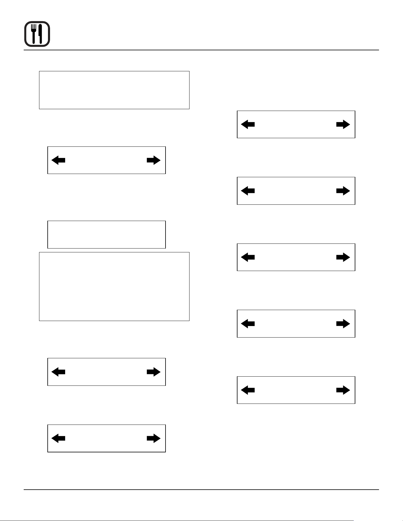
30
Operation
Blodgett IQ2™ Vision Control
Denition: If you are using sensitivity as a tim-
ing mode for single stage stage recipes this
feature must be turned on.
Use the PROGRAM ARROW KEYS (4) to select ei-
ther Yes or No. Press the PROGRAM KEY (3).
8. The display reads:
Shelf 1 Sense
XXX
Use the PRODUCT KEYS (14) to enter sensitivity
level of 1-9 for shelf 1. Press the PROGRAM KEY
(3). Repeat for shelves 2-5.
9. The display reads:
Preheat Time
XXX
Denition: This function programs time for the
oven to idle after reaching the preheat temper-
ature allowing heat to saturate the oven cavity.
The preheat time only applies to the initial pre-
heat after a cold start. This is strictly a prompt,
the user may begin a bake cycle even with the
preheat prompt displayed.
Use the PRODUCT KEYS (14) to enter a preheat
time. Press the PROGRAM KEY (3).
10. The display reads:
Recipe Stage
YES
Use the PROGRAM ARROW KEYS (4) to select ei-
ther Yes or No. Press the PROGRAM KEY (3).
11. The display reads:
Recipe Name
YES
This enables you to program a product name. Use
the PROGRAM ARROW KEYS (4) to select either
Yes or No. Press the PROGRAM KEY (3).
12. The display reads:
Recipe Shelf
YES
Use the PROGRAM ARROW KEYS (4) to select ei-
ther Yes or No. Press the PROGRAM KEY (3).
13. The display reads:
Recipe Fan Speed
YES
Use the PROGRAM ARROW KEYS (4) to select ei-
ther Yes or No. Press the PROGRAM KEY (3).
14. The display reads:
Recipe Fan Cycle
YES
Use the PROGRAM ARROW KEYS (4) to select ei-
ther Yes or No. Press the PROGRAM KEY (3).
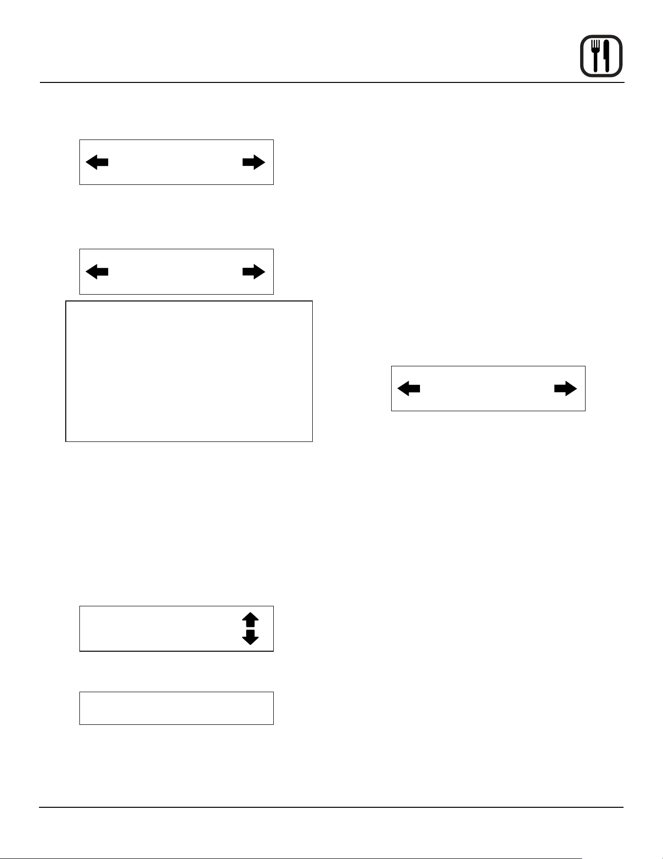
15. The display reads:
Recipe Alarm
YES
Use the PROGRAM ARROW KEYS (4) to select ei-
ther Yes or No. Press the PROGRAM KEY (3).
16. The display reads:
Recipe Hold
YES
Use the PROGRAM ARROW KEYS (4) to select ei-
ther Yes or No. Press the PROGRAM KEY (3).
31
Operation
17. The display reads:
Recipe Timing
YES
Use the PROGRAM ARROW KEYS (4) to select ei-
ther Yes or No. Press the PROGRAM KEY (3).
18. The display reads
Global Timing
YES
Denition: There are 3 options for timing
mode when shelf cooking: Straight, Flex and
Sensitivity. Straight has no time adjustment.
Flex adjusts the cook time to compensate for
any dierence between the setpoint and actual
temperature. Sensitivity enables a product key
to have a ex adjustment for each of the ve
shelves. Sensitivity values are set in the man-
ager level programming.
Use the PROGRAM ARROW KEYS (4) to select the
timing mode. Press the PROGRAM KEY (3).
Programming the PRODUCT NAME
NOTE: Use these instructions to modify an existing
name, to add a product name or to delete a name
already in the library.
NOTE: Names may be up to 16 characters long and can
contain letters and numbers.
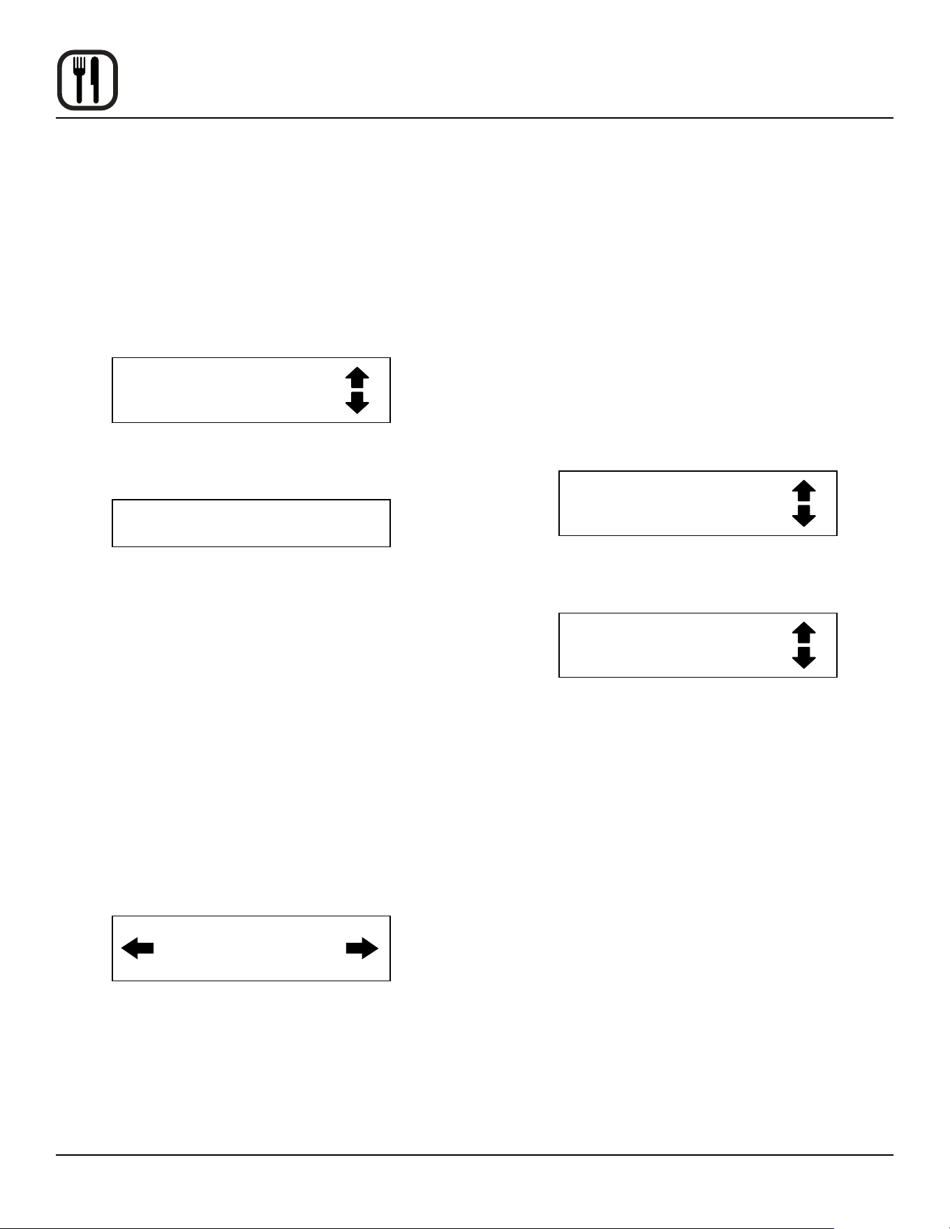
1. After entering the manager level programming (see
page 36) the display reads:
System
Prod Name Lib
With ProdName Lib highlighted, press the PRO-
GRAM KEY (3) to select. The display reads:
Product Name Lib
2. Use the up and down PROGRAM ARROW KEYS (4)
to scroll through the existing product names. Or press
the PRODUCT KEY (14) that corresponds with the
rst letter of the name you are looking for. Then use
the PROGRAM ARROW KEYS (4) to scroll to the de-
sired name.
3. Press the SCAN KEY (9) to edit the name.
4. Use the PRODUCT KEYS (14) to edit the product
name. Press the right arrow key to advance to the
next character.
To clear the product name, press the TEMP/TOG-
GLE/CLEAR KEY (11).
NOTE: Use product key 1 for spaces, periods, quo-
tation marks and underlines.
5. Once the product name has been entered, press the
PROGRAM KEY (3). The display reads:
Save Library
ADD
Use the PROGRAM ARROW KEYS (4) to select ei-
ther ADD, MODIFY or CANCEL. Select ADD to cre-
ate a new product name. Select MODIFY to change
an existing product name. Select CANCEL to exit the
edit mode without saving your changes.
NOTE: To delete an exsisting product name, nd the
name in the product library. Press the TEMP/
TOGGLE/CLEAR KEY (11) to clear the entire
product name. Then select MODIFY to over-
write the name with a clear screen.
6. Press the PROGRAM KEY (3) to exit the product
name library.
Blodgett IQ2™ Vision Control
32
Operation
Blodgett IQ2™ Vision Control
Programming the ALARM NAME
NOTE: Use these instructions to modify an existing
name, to add an alarm name or to delete a name
already in the library.
NOTE: Names may be up to 16 characters long and can
contain letters and numbers.
1. After entering the system level programming (see
page 36) the display reads:
System
Prod Name Lib
Use the PROGRAM ARROW KEYS (4) to highlight
Alarm Lib. Press the PROGRAM KEY (3) to select.
The display reads:
Alarm Name Lib
2. Use the up and down PROGRAM ARROW KEYS (4)
to scroll through the existing alarm names. Or press
the PRODUCT KEY (14) that corresponds with the
rst letter of the name you are looking for. Then use
the PROGRAM ARROW KEYS (4) to scroll to the
desired name.
3. Press the SCAN KEY (9) to edit the name.
4. Use the PRODUCT KEYS (14) to edit the alarm
name. Press the right arrow key to advance to the
next character.
To clear the alarm name, press the TEMP/TOGGLE/
CLEAR KEY (11).
NOTE: Use product key 1 for spaces, periods, quo-
tation marks and underlines.
5. Once the alarm name has been entered, press the
PROGRAM KEY (3). The display reads:
Save Library
ADD
Use the PROGRAM ARROW KEYS (4) to select ei-
ther ADD, MODIFY or CANCEL. Select ADD to cre-
ate a new alarm name. Select MODIFY to change an
existing alarm name. Select CANCEL to exit the edit
mode without saving your changes.
NOTE: To delete an exsisting alarm name, nd the
name in the product library. Press the TEMP/
TOGGLE/CLEAR KEY (11) to clear the entire
alarm name. Then select MODIFY to over-
write the name with a clear screen.
6. Press the PROGRAM KEY (3) to exit the alarm name
library.
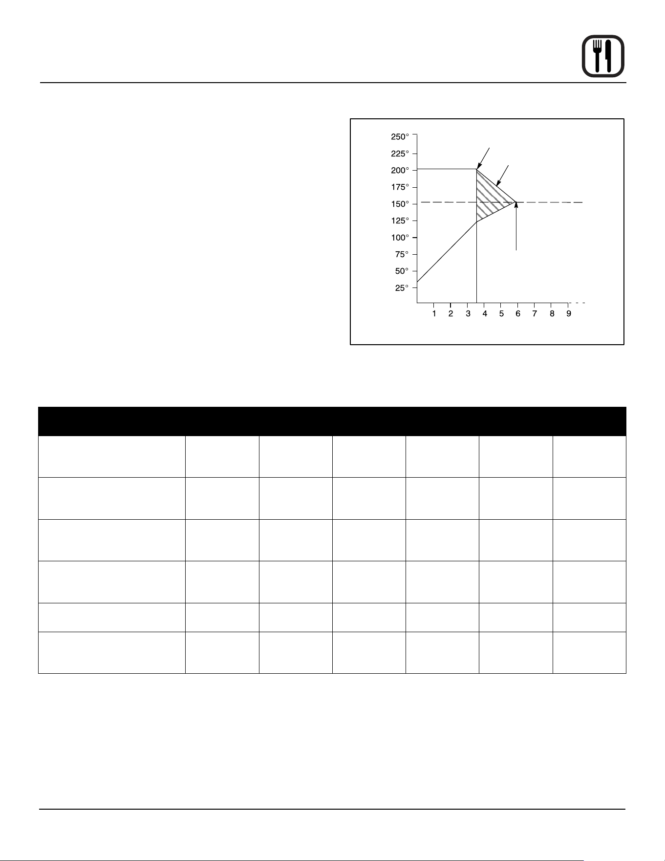
Exiting the system program mode
1. The display reads:
System
Prod Name Lib
Use the PROGRAM ARROW KEYS (4) to scroll up
until Exit is highlighted. Press the PROGRAM KEY
(3). The display reads:
Product Cnt
Programming
Use the PROGRAM ARROW KEYS (4) to scroll up
until Exit is highlighted. Press the PROGRAM KEY
(3) to exit the programming mode.
33
Operation
How Cook & Hold Works
With the optional COOK & HOLD feature, meat is roasted
at lower temperatures for longer periods of time. This pre-
serves avor and tenderness and prevents over drying.
There are three phases in cook and hold roasting.
• Primary Cooking - controlled by the COOK & HOLD
TIMER. The meat is cooked at a low temperature
until approximately 2/3 done.
• Cooking from Stored Heat - when the primary cook
time expires, the oven automatically switches to
HOLD. The product continues to cook from the heat
stored in the oven. Meat must remain in the hold
cycle for a minimum of 1-1/2 to 2 hours before being
served.
• Hold - holds the product for several hours before
serving without loss of moisture or tenderness.
All meat should be completely thawed by refrigeration. Us-
ing frozen meat increases the cook time causing shrink-
age.
Temperature (°F)
Time (hours)
Oven Temp
Oven switches from cook to hold
Stored heat
Product may be
held up to 16 hours
Product may be
removed and served.
Meat Temp
Figure 14
PRODUCT
COOK
TEMP.
HOLD TEMP. QUANTITY
COOK TIME
(HRS)
MIN. HOLD
TIME (HRS)
TOTAL TIME
(HRS)
Prime rib, bone cap o
14-18 lbs. (6.4-8.1 kg)
200°F
93°C
140°F
60°C
1
3
6
3
3-1/4
3-1/2
1
1-1/2
2
4
4-3/4
5-1/2
Prime rib, bone cap on
14-18 lbs. (6.4-8.1 kg)
200°F
93°C
140°F
60°C
1
3
6
3-1/2
4
4-1/2
1
1-1/2
2
4-1/2
5-1/2
6-1/2
Top or bottom rounds
20-22 lbs. (9.1-10.0 kg)
200°F
93°C
140°F
60°C
1
3
6
3-1/2
4
4-1/2
1
1-1/2
2
4-1/2
5-1/2
6-1/2
Pork roast or ham
10-12 lbs. (4.5-5.4 kg)
250°F
121°C
170°F
76°C
2
4
6
4
4-1/4
4-1/2
1
1-1/2
2
5
5-3/4
6-1/2
Turkey
20-22 lbs. (9.1-10.0 kg)
250°F
121°C
170°F
76°C
1
6
3-1/4
4
1
1-1/2
4-3/4
5-1/2
Leg of Lamb, bone in
8-10 lbs. (4.36-4.5 kg)
225°F
107°C
160°F
71°C
2
4
6
2-1/2
2-3/4
3
1
1-1/2
2
3-1/2
4-1/4
5

34
Operation
General Guidelines for Operating Personnel
COOK TIMES AND TEMPERATURES
Preheating the oven
Always preheat the oven before baking or roasting. We
recommend preheating 50°F (28°C) above the cook tem-
perature to oset the drop in temperature when the doors
are opened and cold product is loaded into the oven. Set
the thermostat to the cook temperature after the product
is loaded.
NOTE: For frozen product, preheat the oven 100°F
(56°C) above the cook temperature.
Cook Temperatures
Generally, cook temperatures should be 50°F (28°C) low-
er than deck or range oven recipes. If the edges of the
product are done but the center is raw, or if there is color
variation, reduce the thermostat setting another 15-25°F
(10-15°C). Continue to reduce the cook temperature on
successive loads until the desired results are achieved.
NOTE: Cooking at excessive temperatures will not re-
duce cook time, it will produce unsatisfactory bak-
ing and roasting results.
Cook Time
Check the product in about half the time recommended
for deck or range oven recipes. Record times and tem-
peratures which provide best results for future reference.
NOTE: Cook time will vary with the amount of product
loaded, the type of pan and the temperature.
OPERATING TIPS
Pans and Racks
Product or pan height determines how many racks are
used. The oven holds up to ten 18” x 26” (45.7 x 66.0 cm)
bun pans.
Load the oven from the bottom, centering the pans on the
rack. Never place a pan or aluminum foil on the bottom
of the oven. This obstructs the ow of air and results in
uneven baking and roasting.
Roasting
To reduce shrinkage when roasting, place meat directly on
the racks. Place a sheet pan one-half full of water in the
bottom rack position. The water evaporates, increasing
humidity in the oven chamber. The pan catches grease
from the meat, making oven cleaning easier.
Baking
Weigh the product to ensure equal distribution in each
pan. Varying amounts of product will cause uneven bak-
ing results.
Fans
The fan must be operating for the oven to heat. Use the
Pulse Plus feature to allow light or liquid product to set
in the pan and to avoid rippling towards the fan. If your
oven is not equipped with this feature use the following
procedure.
1. Preheat the oven 25°F (15°C) above the baking tem-
perature.
2. Load the oven with product. Close the doors.
3. Set the thermostat to the baking temperature.
4. Turn the oven o.
5. Allow the product to set for 5-7 minutes with the fan
o. The residual heat in the oven sets the product.
6. Turn the oven on for the remainder of the bake.
Lights
Turn the oven lights o when not viewing the product.
Leaving the lights on for extended periods of time short-
ens the bulb life considerably.
35
Operation
Suggested Times and Temperatures
PRODUCT TEMPERATURE TIME # SHELVES
Meats
Hamburger Patties (5 per lb)
Steamship Round (80 lb. quartered)
Standing Rib Choice (20 lbs, trimmed, rare)
Banquet Shell Steaks (10 oz. meat)
Swiss Steak after Braising
Baked Stued Pork Chop
Boned Veal Roast (15 lbs.)
Lamb Chops (small loin)
Bacon (on racks in 18” x 26” pans)
400°F (205°C)
275°F (135°C)
235°F (115°C)
450°F (235°C)
275°F (135°C)
375°F (190°C)
300°F (150°C)
400°F (205°C)
400°F (205°C)
8-10 mins.
2 hrs 45 mins.
2 hrs 45 mins.
7-8 mins.
1 hr.
25-30 mins.
3 hrs. 10 mins.
7-8 mins.
5-7 mins.
10
2
2
5
5
5
2
5
10
Poultry
Chicken Breast & Thigh
Chicken Back & Wing
Chicken (21/2 lbs. quartered)
Turkey Rolled (18 lb. rolls)
350°F (175°C)
350°F (175°C)
350°F (175°C)
310°F (155°C)
40 mins.
35 mins.
30 mins.
3 hrs 45 mins.
5
5
5
3
Fish and Seafood
Halibut Steaks, Cod Fish (frozen 5 oz)
Baked Stued Lobster (21/2 lb.)
Lobster Tails (frozen)
350°F (175°C)
400°F (205°C)
425°F (220°C)
20 mins.
10 mins.
9 mins.
5
3
5
Cheese
Macaroni & Cheese Casserole
Melted Cheese Sandwiches
350°F (175°C)
400°F (205°C)
30 mins.
8 mins.
5
10
Potatoes
Idaho Potatoes (120 ct.)
Oven Roasted Potatoes (sliced or diced)
400°F (205°C)
325°F (165°C)
50 mins.
10 mins.
5
5
Baked Goods
Frozen Berry Pies (22 oz)
Fresh Apple Pie (20 oz.)
Pumpkin Pies (32 oz.)
Fruit Crisp
Bread (24 - 1 lb. loaves)
Southern Corn Bread
Baking Soda Biscuits
Brown & Serve Rolls
Sheet Cakes (5 lb. mixed batter per pan)
Chocolate Cake
Brownies
325°F (150°C)
350°F (175°C)
300°F (150°C)
300°F (150°C)
325°F (155°C)
375°F (190°C)
400°F (205°C)
350°F (175°C)
325°F (160°C)
325°F (160°C)
325°F (150°C)
35 mins.
25-30 mins.
30-50 mins.
25 mins.
30 mins.
15-20 mins.
6 mins.
15 mins.
16-18 mins.
20 mins.
15 mins.
5 (30 pies)
5 (30 pies)
5 (20 pies)
5
3
5
5
5
5
5
5
NOTE: Actual times and temperatures may vary considerably from those shown above. They are aected by weight of
load, temperature of the product, recipe, type of pan and calibration of thermostat. Should your recipe vary, write
in your proven time and temperature for ready reference.

36
Maintenance
Cleaning and Preventative Maintenance
CLEANING THE OVEN
Painted and stainless steel ovens may be kept clean and
in good condition with a light oil.
1. Saturate a cloth, and wipe the oven when it is cold.
2. Dry the oven with a clean cloth.
On the stainless front or interiors, deposits of baked on
splatter may be removed with any non-toxic industrial
stainless steel cleaner. Heat tint and heavy discoloration
may be removed with any non-toxic commercial oven
cleaner.
1. Apply cleaners when the oven is cold. Always rub
with the grain of the metal.
The porcelain interior can be cleaned with any commer-
cial oven cleaner. Be sure caustic cleaning compounds
DO NOT come in contact with the blower wheel and the
aluminized steel panel directly behind it.
1. Remove the racks, rack supports and blower wheel
from the oven.
2. Soak the parts in a solution of ammonia and water.
3. Reinstall after cleaning.
NOTE: If the oven is moved the restraint must be recon-
nected after the unit is returned to it’s regular po-
sition.
Weekly Cleaning – All Models
In addition to the daily cleaning it is necessary to clean
the air intakes on a weekly basis. Air intakes provide nec-
essary cooling air to the internal components. They are
generally located on the rear and sides of the equipment.
PREVENTATIVE MAINTENANCE
The best preventative maintenance measures are, the
proper installation of the equipment and a program for
routinely cleaning the ovens.
Annual Maintenance
This oven requires no lubrication, however, the venting
system should be checked annually for possible deterio-
ration resulting from moisture and corrosive ue products.
If maintenance or repairs are required, contact your local
Blodgett service company, a factory representative or the
Blodgett Oven company.
WARNING!!
Always disconnect the appliance from the
power supply before servicing or cleaning.
37
Maintenance
Troubleshooting Guide
POSSIBLE CAUSE(S) SUGGESTED REMEDY
SYMPTOM: Oven will not re.
• Gas turned o.
• Oven not plugged in.
• Power switch on the control panel is o.
• Control set below ambient temperature.
• Doors are open.
• Computerized controls - error code on display.
• Turn the gas valve to ON.
• Plug in electrical supply cord.
• Set the control panel to COOK or OVEN ON.
• Set to desired cook temperature.
• Close doors.
• *
SYMPTOM: Oven does not come to ready.
• The oven has not reached preheat temperature.
• Gas valve not turned on completely.
• The quick disconnect is not connected.
• Gas pressure to oven is too low.
• Fan delay feature may be activated, if applicable.
• Internal problem with main temperature control.
• Wait for oven to reach preheat temperature.
• Check the gas valve, turn on fully if necessary.
• Reconnect the quick connect. Check all gas
connections.
• Call your local gas representative.
• Deactivate fan delay feature.
• *
SYMPTOM: Convection fan does not run.
• Oven is not plugged in.
• Oven is not set to the cook mode.
• Circuit breaker tripped.
• Fan delay feature may be activated, if applicable.
• Doors are open
• Plug in electrical supply cord.
• Set the control panel to COOK or OVEN ON.
• Reset the breaker.
• Deactivate fan delay feature.
• Close doors.
SYMPTOM: General baking problems.
• Computerized controls - incorrect product
programming.
• Thermostat out of calibration.
• Improper oven venting.
• Reprogram control per Operation section.
• *
• *
*Denotes remedy is a dicult operation and should be performed by qualied personnel only. It is recommended, how-
ever, that All repairs and/or adjustments be done by your local Blodgett service agency and not by the owner/operator.
Blodgett cannot assume responsibility for damage as a result of servicing done by unqualied personnel.
WARNING!!
Always disconnect the power supply before cleaning or servicing the oven.