
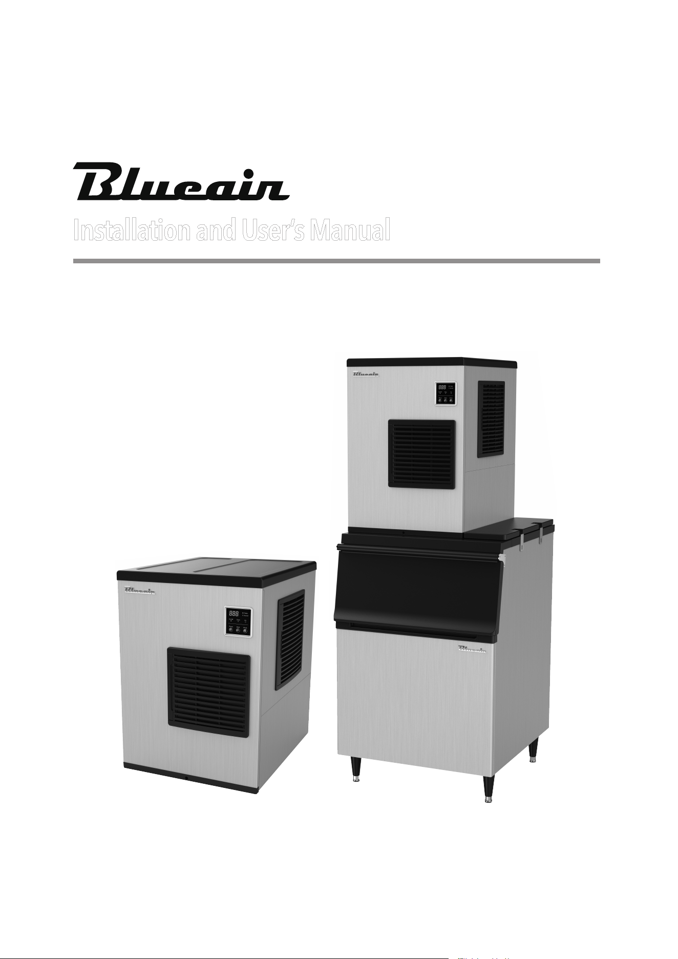
Installation and User’s Manual
BLMI-300A
BLMI-500A
BLMI-650A
BLMI-900A
ver.201803_02
I512A-202
2
3
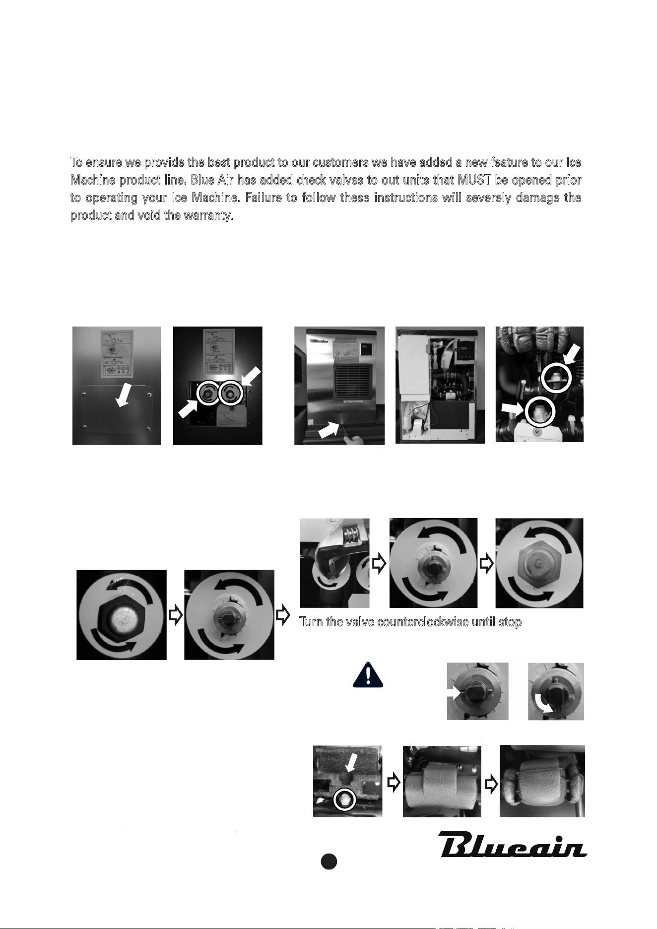
IMPORTANT!!
Location of Valves
(BLUI-150 model does not come with any valves)
Guide to Opening Valves
After open the valves,
Cover the valves
with the Insulation and ties provided.
BLUI-250A(Undercounter) BLMI-300A/500A/500AD/650A/900A(Modular)
To ensure we provide the best product to our customers we have added a new feature to our Ice
Machine product line. Blue Air has added check valves to out units that MUST be opened prior
to operating your Ice Machine. Failure to follow these instructions will severely damage the
product and void the warranty.
• Located on back panel of unit.
• Disassemble the cover to access the
valves.
• Located on the inside of the unit.
• Disassemble the front cover to access the valves.
• Uncap the safety cap
•
Turn the valve counterclockwise until stop
• Put the safety caps back.
Close Open
www.blueairfse.com
Contact / [email protected]
Tel. 1-866-677-8500 / Customer Service
MUST OPEN
BOTH VALVES

2
3
Table of Contents
Freight Claim Procedure(Important)
1.
Specifications .................................................................................. 5
1.1 Technical Specification
1.2 Product Dimensions
1.3 Accessories Included in the Unit
1.4 How to Determine Model Names and Serial Numbers
2. Installation & Operations Guide ................................................ 11
2.1 Location Requirements
2.2 Installation Requirements
2.3 Electrical Requirements
2.4 Installation Checklist
2.5 How to Remove Machine Panel
2.6 Bin Installation
2.7 Bin S/W Installation
2.8 Water supply & Drain Connections
2.9 Wire
2.10 Final Check
2.11 Test Run
3. Operation ........................................................................................ 21
3.1 Button
3.2 Status Light
3.3 7-Segments
3.4 Operation Cycle
3.5 Safety
3.6 Error Codes
4. Maintenance & Cleaning ............................................................. 25
4.1 Maintenance Period
4.2 Interior Cleaning & Sanitizing Procedure
4.2.1 Cleaning Procedure
4.2.2 Sanitizing Procedure
4.2.3 Product Disassembly
4.3 Level sensor Cleaning
4.4 Exterior Cleaning
4.5 Storage Container and Scoop
4.6 Air Filter
4.7 Condenser
4.8 How to Prepare Unit for Long Term Storage

4
5
Freight Claim Procedure(Important)
Inspect Immediately
This product has been carefully inspected and packed in accordance with the
carrier’s packing specifications. Responsibility for safe delivery has been
assumed by the carrier. If loss or damage occurs, you as the consignee must file
a claim with the carrier and hold the container for carrier’s inspection.
Visible Loss or Damage
Any external evidence of loss or damage must be fully described and noted on
your freight bill or express receipt and signed by the carrier’s agent. The claim
should be filed on a form available from the carrier.
Concealed Loss or Damage
Concealed loss or damage should be reported to the carrier and vendor within 24
hours of delivery.
After 24 hours the seller is not responsible for any freight damage incurred.
Keep the product as well as all of the original packaging material in a receiving
area for carrier's inspection.
Warning
Connect to potable water supply only.
Adult supervision is required for safe use either by children under 8 years of age
or the developmentally disabled.
The warranty does not apply to the followings.
Repair or replacement of parts required due to misuse, improper care or storage,
negligence, alteration, use of incompatible supplies or lack of specified maintenance.
Regular maintenance items.
Failures caused by improper or erratic voltages, adverse environmental or water
conditions, improper drainage, interruption in electrical or water supply.
Improper or unauthorized repair.
Any ice machine that has been installed and/or maintained inconsistent with the
instructions provided by Blue Air
4
5
1. Specifications
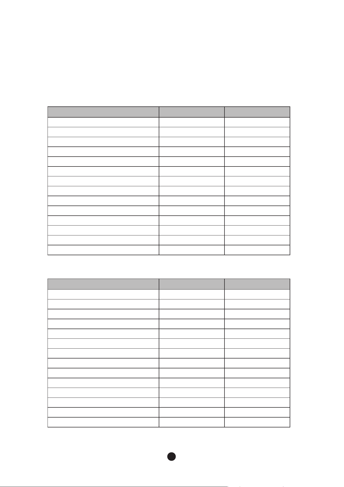
1.1 Technical Specification
300A 500A
Condenser
Air Cooling Air Cooling
Rated Voltage
115V/60Hz/1Ph 115V/60Hz/1Ph
Rated Ampere
8A 14A
Compressor
115 V 37 LRA 6.35RLA 115 V 57 LRA 11.4RLA
Pump
115V 0.53FLA 59.9W 115V 0.53FLA 59.9W
Fan
115V 0.68FLA 75.2W 115V 0.68FLA 75.2W
Maximum Breaking Capacity of Fuse Size
15A 25A
Designed Pressure
HI –580 / LO –320 psig HI – 580 / LO –320 psig
Refrigerant
R-410A 400g (14.1OZ) R-410A 450g (15.8OZ)
Safety Approval
UL UL
Sanitation Approval
ETL ETL
Energy Star
Certified Certified
CE
N/A N/A
KC
N/A N/A
650A 900A
Condenser
Air Cooling Air Cooling
Rated Voltage
208-230V60Hz/1Ph 208-230V/60Hz/1Ph
Rated Ampere
9A 9A
Compressor
208~230 V 29LRA 6.8 RLA
208~230V 41LRA 7.6RLA
Pump
115V 0.55FLA 63.5W 115V 0.55FLA 63.5W
Fan
115V 0.68FLA 75.2W 115V 0.68FLA 75.2W
Maximum Breaking Capacity of Fuse Size
15A 15A
Designed Pressure
HI –580 / LO –320 psig HI –580 / LO –320 psig
Refrigerant
R-410A 700g (24.6OZ) R-410A 1100g (38.8OZ)
Safety Approval
UL UL
Sanitation Approval
ETL ETL
Energy Star
Certified N/A
CE
N/A N/A
KC
N/A N/A
● Electrical & Refrigerant Data
6
7
No Model Rated Voltage
AT 70 °F / WT 50°F
AT 21 °C / WT 10°C
1 300A 115V/60Hz/1Ph 340 lbs/day (154 kg/day)
2
500A 115V/60Hz/1Ph 538 lbs/day (244 kg/day)
3
650A 208-230V60Hz/1Ph 625 lbs/day (283 kg/day)
4
900A 208-230V60Hz/1Ph 890 lbs/day (404 kg/day)
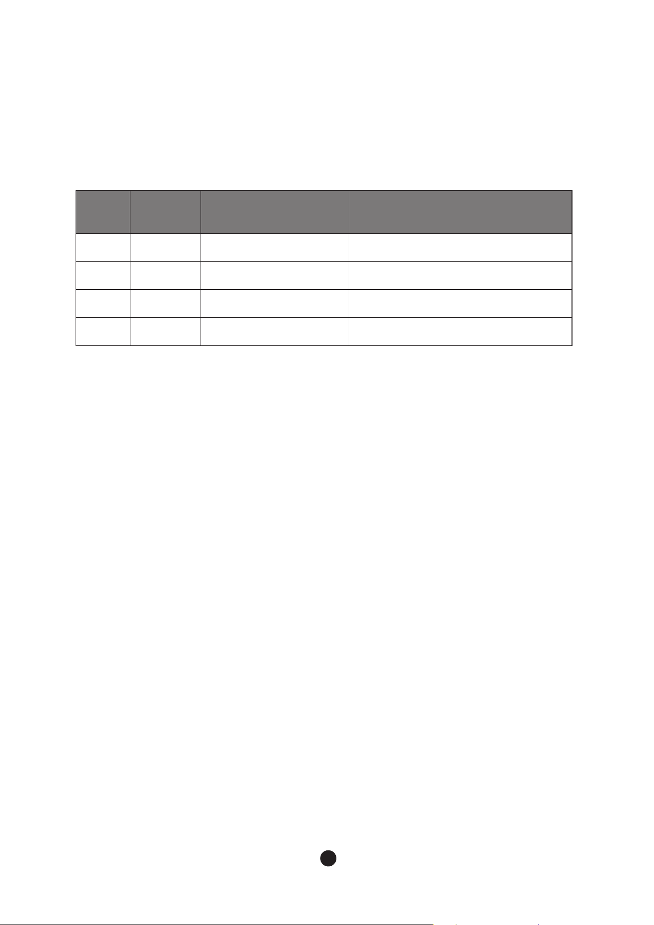
● Approximate Ice Production
6
7
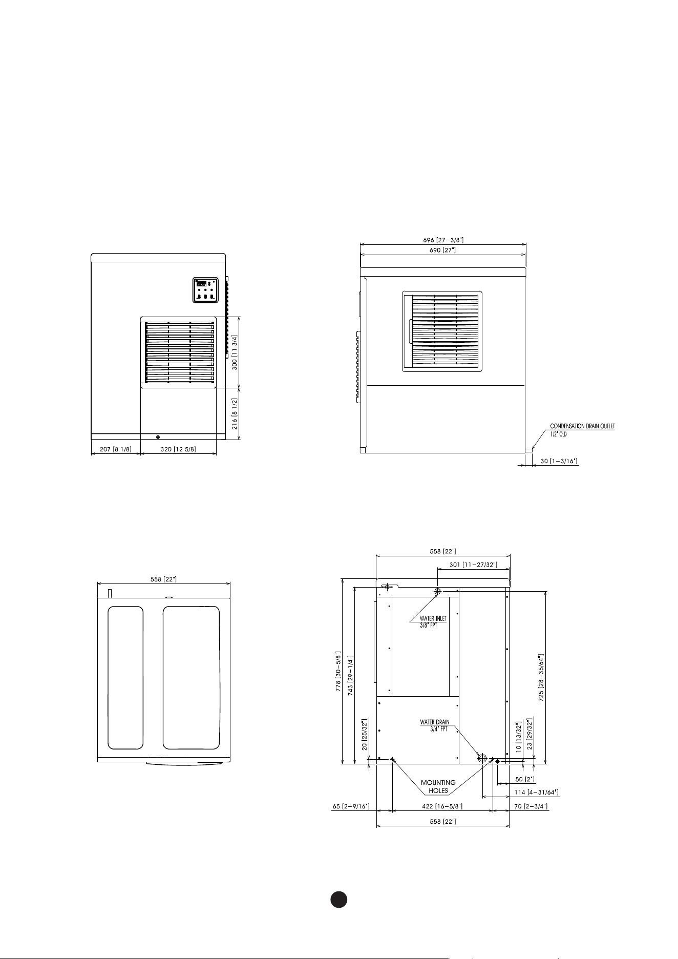
1.2 Product Dimensions
● 300A/500A
FRONT
TOP
SIDE
REAR
8
9
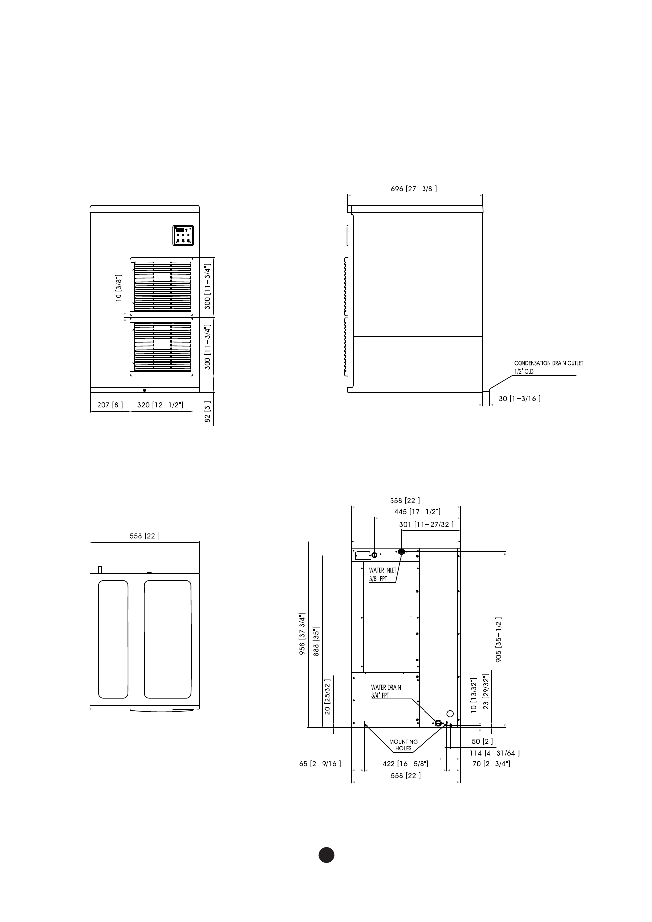
● 650A
FRONT
TOP
SIDE
REAR
8
9
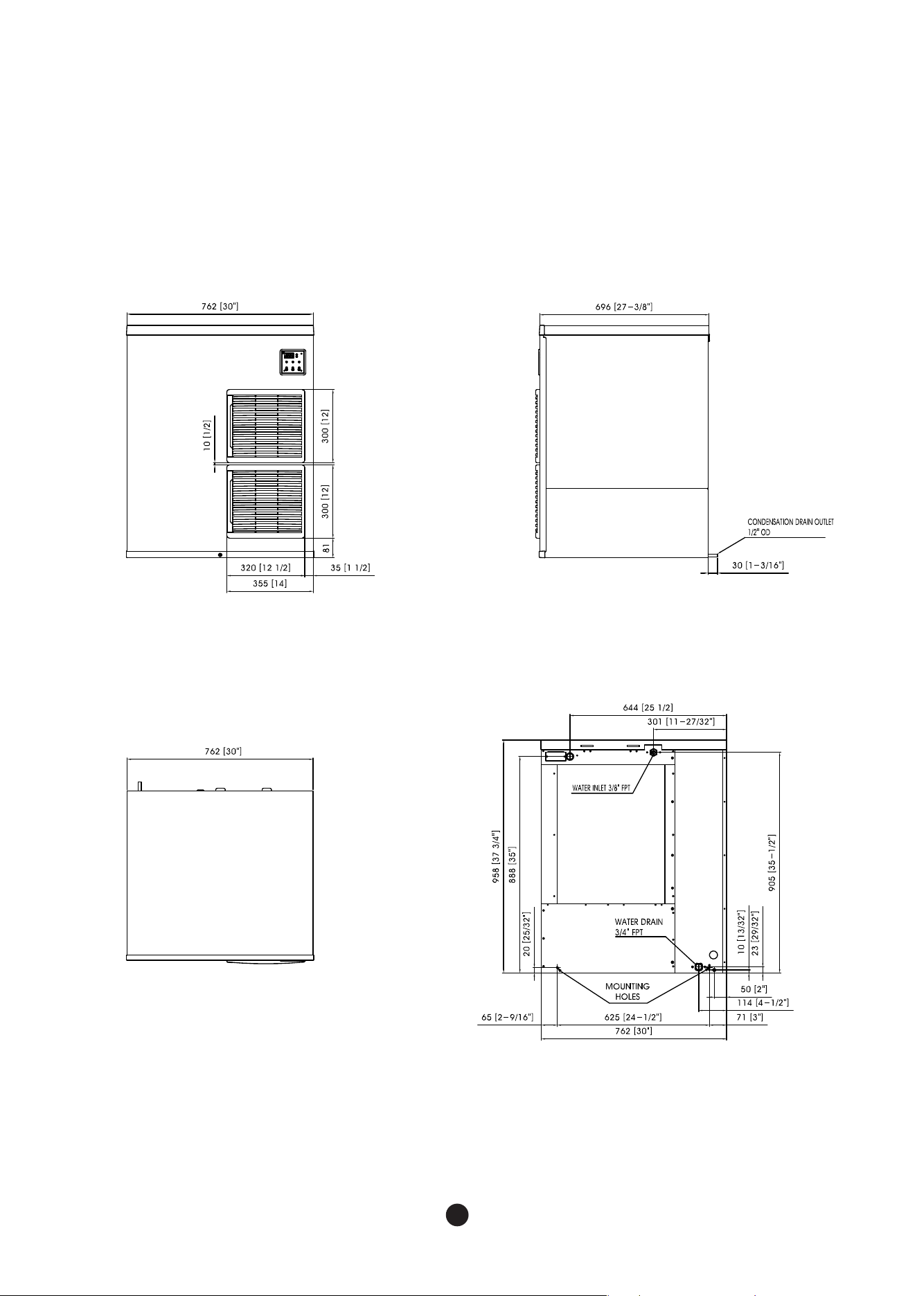
● 900A
FRONT
TOP
SIDE
REAR
10
11
2. Installation & Operation Guide
2.2 Installation Requirements
The installation location of the ice machine should satisfy following conditions.
- If the location does not satisfy these conditions, do not install the machines in that location.
The installment location must be changed to meet following conditions.
- The location should be in indoors and have good ventilation
- The location should not be near a heat source and should not be in direct sunlight
- The operating temperature at the location should be between 45°F- 100°F(7°C- 38°C).
- The location should have access to a water supply, drainage and an easily connected
source of electricity
- The location should not have any obstacles, disturbing air circulation(heat exchange).
- The location should have enough clearance for wiring and plumbing on the rear.
- The location should have no food waste nor food contaminant.
- The location should support the full weight of the machine filled with ice.
- The head and bin should be level.
- The vent of the of ice machine and drain of the bin should be separated.
- The drain tip of the bin should have an air gap.
- The ice machine and bin should be completely cleaned after installation.
- The drain line should be easily separated from the ice machine.
- There must be minimum of (8 inches / 20 cm)of clearance, around, above and below the
ice machine for enough air circulation and maintenance.
- Carefully align the ice machine with the bin to ensure a secure seal.
WARNING
-
The ice machine should be installed, following the local regulations of the country, state and region.
- Read the manual thoroughly before installation. Incorrect installation may cause
malfunction, or bodily injury and death.
- Do not drop tools into the bin or the floor of the unit during installation. It may cause
injure during routine operation of the machine.
- Do not operate unit with enclosure removed. This is marked by a sticker labelled "CAUTION
or WARNING - Parts. Do Not Operate Unit With Enclosure Removed."
(When disassembly for cleaning or similar servicing exposes moving parts.)
2.1 Location Requirements
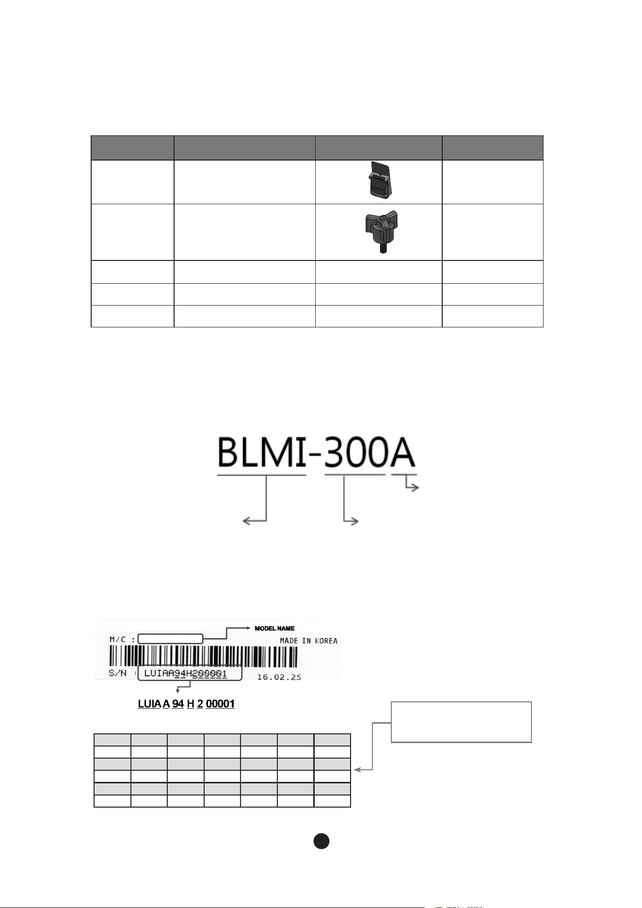
1.3 Accessories Included in the Unit
1.4 How to Determine Model Names and Serial Numbers
1.4.1 Model names
1.4.2 Serial number
No Name Picture Quantity
1 Bin switch 1
2 M5 Bolt 4
3 Screw M6 2
4 Earth Screw 1
5 User Manual 1
BLMI-900A
daily ice production in pound
a (4 digits) : CIS code for specific model
b (1 digit) : Product group
c (2 digits) : Manufacturing site
(supplier code)
d (1 digit) : Manufacturing year
e (1 digit) : Manufacturing month
f (5 digit) : Serial number (00001 ~ 99999)
BL : Blueair
M : Modular
(U:Undercounter)
I : Crescentice
Air - cooled
a b d e fc
Year 2015 2016 2017 2018 2019 2020
Mark G H J K M N
Month Jan. Feb. Mar. Apr. May. Jun.
Mark 1 2 3 4 5 6
Month Jul. Aug. Sep. Oct. Nov. Dec.
Mark 7 8 9 A B C
10
11
2. Installation & Operation Guide
2.2 Installation Requirements
The installation location of the ice machine should satisfy following conditions.
- If the location does not satisfy these conditions, do not install the machines in that location.
The installment location must be changed to meet following conditions.
- The location should be in indoors and have good ventilation
- The location should not be near a heat source and should not be in direct sunlight
- The operating temperature at the location should be between 45°F- 100°F(7°C- 38°C).
- The location should have access to a water supply, drainage and an easily connected
source of electricity
- The location should not have any obstacles, disturbing air circulation(heat exchange).
- The location should have enough clearance for wiring and plumbing on the rear.
- The location should have no food waste nor food contaminant.
- The location should support the full weight of the machine filled with ice.
- The head and bin should be level.
- The vent of the of ice machine and drain of the bin should be separated.
- The drain tip of the bin should have an air gap.
- The ice machine and bin should be completely cleaned after installation.
- The drain line should be easily separated from the ice machine.
- There must be minimum of (8 inches / 20 cm)of clearance, around, above and below the
ice machine for enough air circulation and maintenance.
- Carefully align the ice machine with the bin to ensure a secure seal.
WARNING
-
The ice machine should be installed, following the local regulations of the country, state and region.
- Read the manual thoroughly before installation. Incorrect installation may cause
malfunction, or bodily injury and death.
- Do not drop tools into the bin or the floor of the unit during installation. It may cause
injure during routine operation of the machine.
- Do not operate unit with enclosure removed. This is marked by a sticker labelled "CAUTION
or WARNING - Parts. Do Not Operate Unit With Enclosure Removed."
(When disassembly for cleaning or similar servicing exposes moving parts.)
2.1 Location Requirements
12
13
2.3 Electrical Requirements
WARNING
- Electrical wiring and grounding of the unit should be done in accordance to the applicable
local, state and federallaws and regulations.
- The ice machine must be grounded in accordance to the law and regulations of the country,
state, and region.
Read the following warnings
- The ice machine must be grounded.
- The ice machine must be connected to an exchangeable fuse or circuit breaker.
- Decide the appropriate size of the wire based on the length, thickness, and position of the wires.
- Electrical wiring and ground must be done by a qualified electrician.
● Installation condition
Condition Minimum Maximum
Ambient Temperature
°F
45 100
°C
7 38
Water temperature
°F
45 90
°C
7 32
Water pressure
psig 30 100
kPa 206.8 689.4
Voltage
115V
100 130
220V
208 230
2.3.1 Voltage
2.3.2 Fuse / Circuit Breaker
- When operating the ice machine (with maximized electrical load) range of variation in maximum
voltage allowed is ±10% of the rated voltage.
-Main voltage transformer tab switch must be set to the same input voltage for single phase models,
650A, 900A.
- The ice machine must be wired to an exclusive fuse/circuit breaker
- The circuit breaker must be installed in accordance with applicable local, state and federal regulations.

12
13
2.4 Checklist before Installation
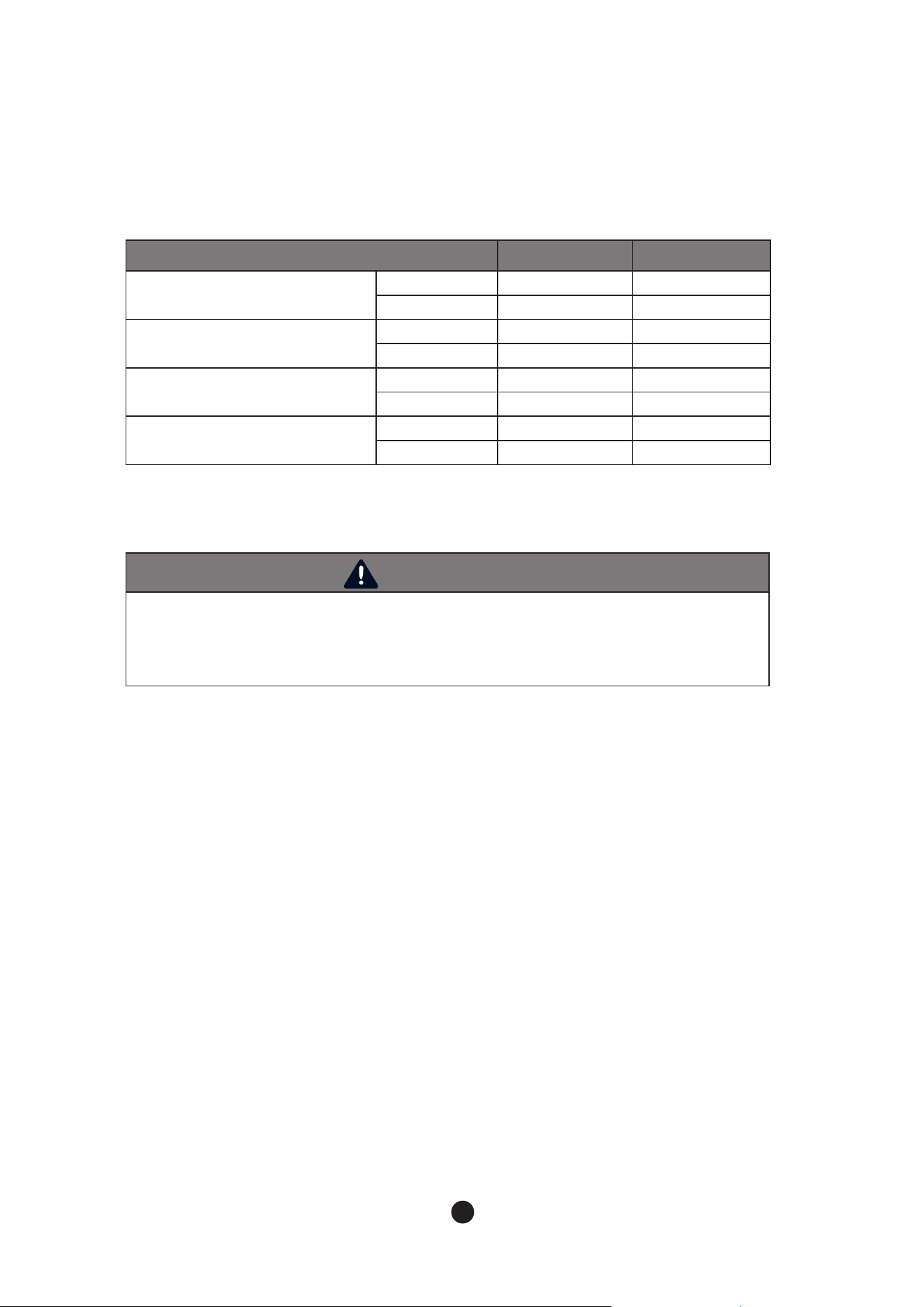
- After unpacking, check the product appearance. If there is damage to the product,
contact your place of purchase.
- Remove packing box, tape and other packing components. If these things are not
removed, the ice machine may not function properly.
- Two manual valves MUST BE OPENED. If not, serious damage will occur.
- Check the name plate for minimum electrical requirement for operating the machine.
Ensure there is sufficient electricity to operate the machine.
- To avoid any damage during installation, remove all panels.
Refer to “2.5 How to Remove Panel”.
- Remove all accessories, enclosed with the ice machine.
- Remove protective plastic film on the panel.
- Check whether a compressor is secure and the fan blade turns freely.
- The ice machine must be installed onto the bin. The available binsare as below.
●
BLIB-500S : 30 inches (762 mm)
●
BLIB-300S : 22 inches (558 mm)
●
For further information, contact the seller.
2.3.3 Power Connection
- Permanently connect : Wiring must be greater than 12AWG.
- Cord connection: Refer to “1.1 Technical Specification” to check detailsof cable size requirements
for the power supply.
14
15
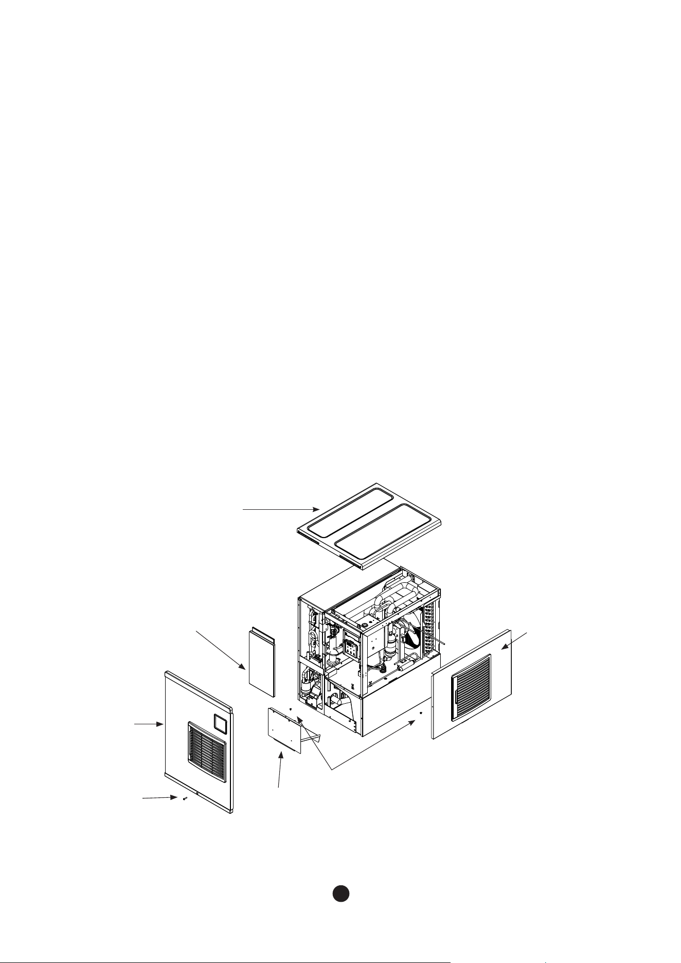
Fig 1
Top panel
Insulation
panel
Screw
Screw
Ice Cover
Side
Panel(R)
Front
panel
2.5 How to Remove Panel
To avoid any damage during installation, remove all panels.
Remove them in the following order by referring to Fig 1.
1. Unscrew the bottom screw of the front panel and store it securely.
2. Remove the front panel by firmly grasping the bottom edge and pulling it up and away
from the unit.
3. Store the front panel securely.
4. Remove the top panel by firmly grasping the front edge and pushing back.
5. Store the top panel securely.
6. Unscrew the Side Panel(R), and store it away securely.
7. Grasp the front of the right panel and pull it forward.
8. Store the right panel securely.
9. The left and back panels cannot be removed.
10. Remove the insulation panel by pushing it up.
11. Unscrew the ice cover and remove the cover by pushing it up.
14
15
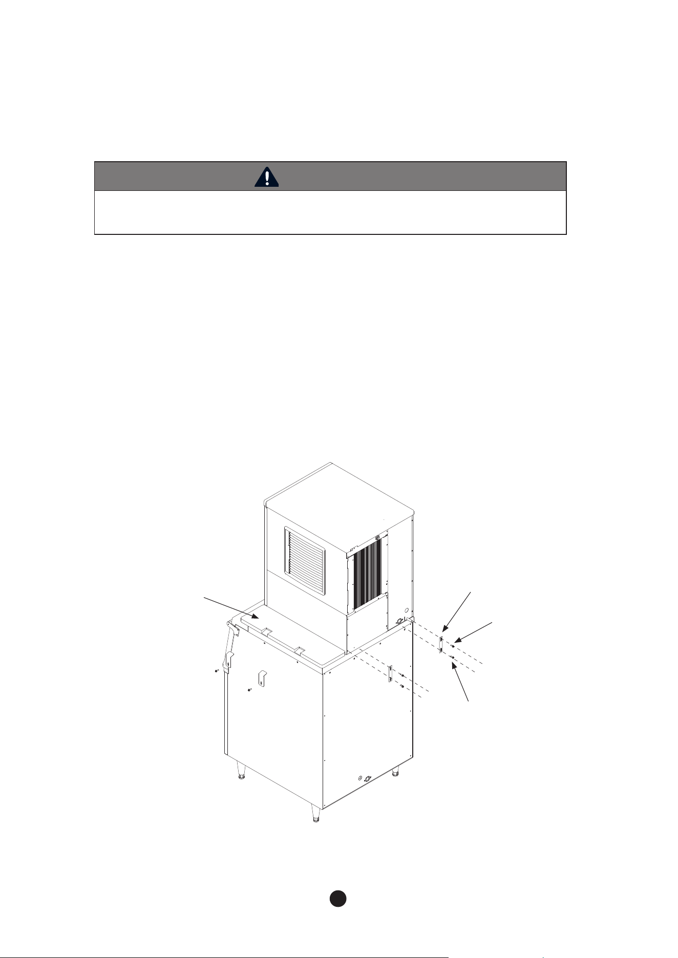
Install the bin in the following order by referring to Fig 2.
1. Position the ice storage bin in the the installation location.
2. If needed, a TOP KIT will need to be installed. For further information, contact the seller.
3. Ensure the bin is level by adjusting the legs on the bin.
4. Attach the ice machine head onto the bin.
5. Attach the ice machine head to the bin at two points on the back with the enclosed
brackets and screws.
2.6 Bin Installation
WARNING
- Check whether the ice machine and ice storage bin are compatible before installation.
The ice machine and bin should be properly attached together.
Fig 2
MODUALR
BRACKET
SCREW(M6)
TOP KIT
SCREW(M5)
16
17
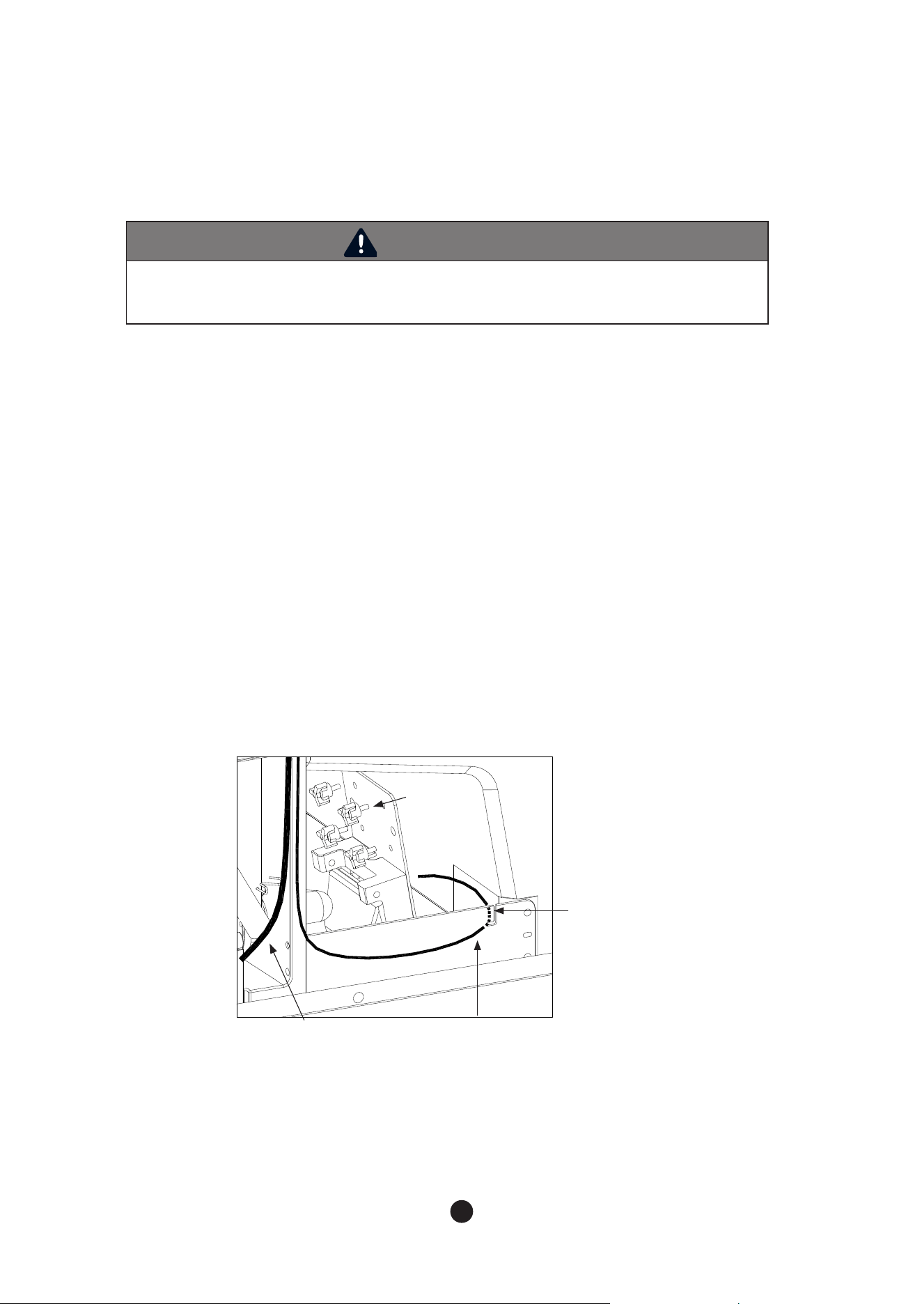
Install bin switch in the following order by referring to Fig 3.
1. When the front panel is removed, enclosed within the machine will be a bin switch,
packed in a plastic.
2. To remove the front panel, refer to “2.5 How to Remove Panel”.
3. Affix the bin switch to the right bottom of the ice machine with fourthumbscrews,
enclosed withthe switch.
4. Position the cable of bin switch into the“J”-type slot of the front supporter by releasing it.
While installing the cable ensure it is not blocking any ice are dropping into the bin.
5. After affixing the cable alongside the Pump motor harness connect it to the blue connector at
the top frame.
2.7 Bin Switch Installation
WARNING
- Bin switch should be equipped before operating the ice machine.
If it is not properly equipped, it might cause a breakdown or malfunction during ice storage.
Fig 3
Thumbscrew
“J” Slot
Supporter frontPump motor
harness
16
17
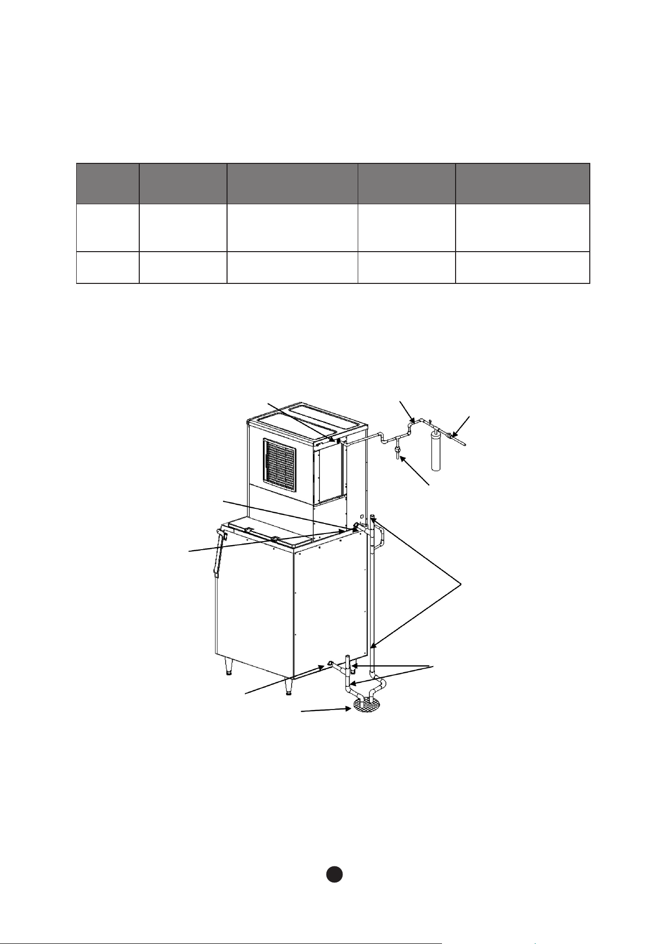
2.8.1
Water Supply
-Depending on the location where the ice machine is installed, the ice machine may
require a water filtration system to prevent formation of scale and removing impurities and
chlorine from the water supply.
2.8.2
Water Supply Line
Refer to following instructions for installing the water supply line.
- Do not connect a hot water system to the ice machine.
- Water pressure must be between 30 ~ 100 psig(206.8-689.4kPa).
- Water supply line must have a shut off valve.
- Water supply line must be insulated to prevent condensation.
2.8.3
Drainage Line
To prevent backflow of the ice machine and storage container, refer to following
instructions for install a drainage line.
- For adequate drainage, a gradient of 1 inch for every 3.3 feet(2.5cm per meter) is needed.
- Do not install any trap.
- Do not connect drainage pipe directly into the sewage pipe.
- There must be a minimum of a 2 inch (50mm)air gap vertically between end of the drainage
pipe and the drain hole.
- Must install a vent.
- Do not combine drain lines for the machine head and the ice storage bin.
- The machine applies gravity drains and does not prevent counter-flow. If you want parts for preventing it,
they must be purchased separately.
2.8 Water Supply & Drain Connections
WARNING
- Installation of water supply and pipe system must be done in accordance to
local, state and federal laws and regulations.
- The ice machine is to be installed with adequate backflow protection to comply
with applicable local, state and federal laws and regulations.
- Water pipe work must be done by a qualified service technicians.
18
19
Fig 7
* Leave a 2”(50mm) vertical air gap between the end of each pipe and the drain
Fig 4
● Conditions for water supply and drainage
Location
Water
temperature
Water
pressure
connecting
fitting size
Size of
connecting hose
Water inlet
7°C (45°F) Min.
32°C(90°F) Max.
30 psig(206.8kPa) Min.
100 psig(689.4kPa) Max.
3/8” FPT ID 1/4” copper pipe(Min.)
Drain - - 3/4” FPT ID
3/4” Hard
pipe(Min.)
Water supply inlet
-3/8" FPT
Minimum 1/4" ID
Copper pipe
Condensation
drain outlet
-3/8" OD Hard tube
Ice maker
drain outlet
-3/4" FPT
Bin drain outlet
-3/4" FPT
Shut-Off
valve
Drain valve
Vent tube
Minimum 3/4" ID
Hard pipe
Floor drain
18
19
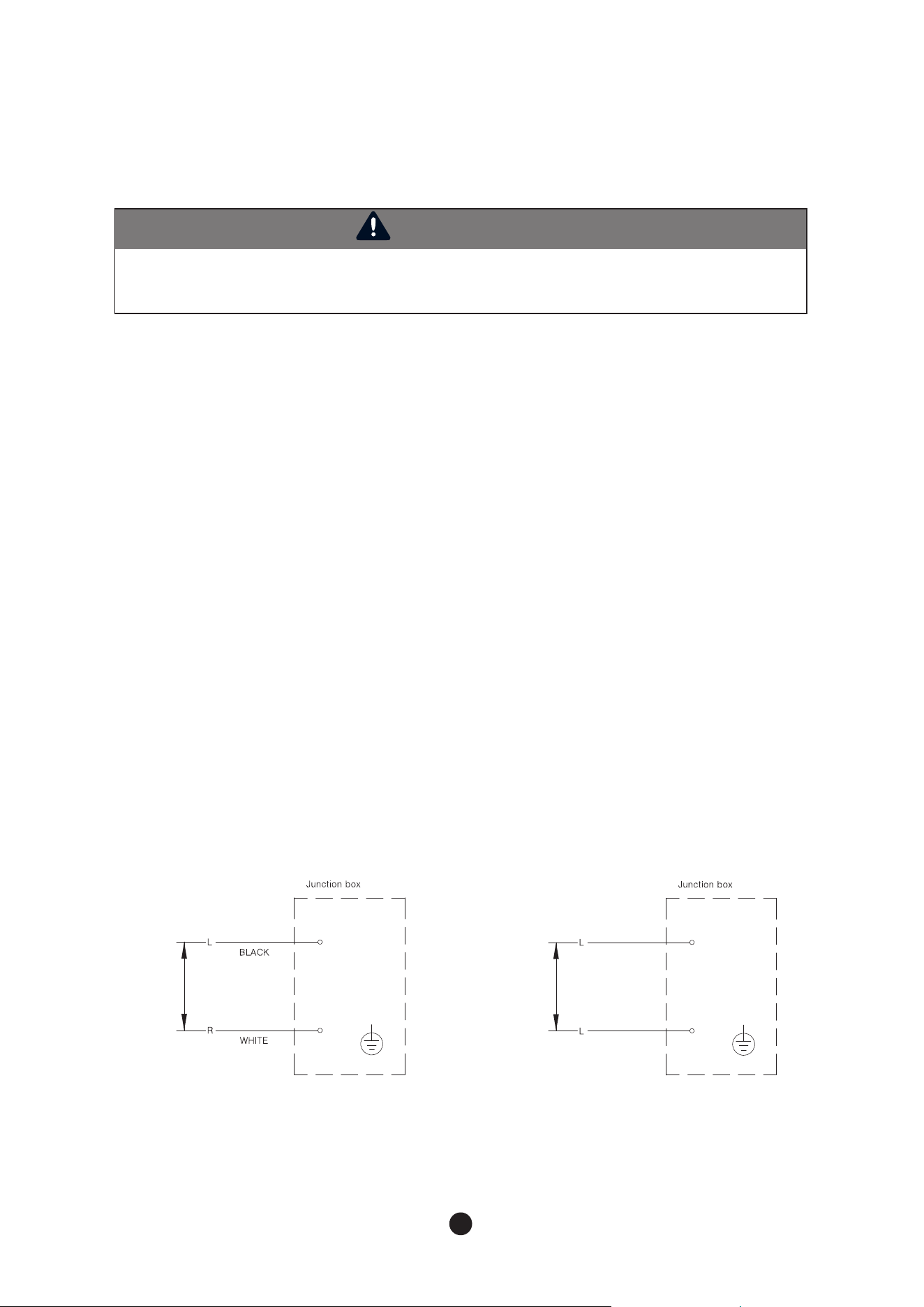
Fig 5
- The machine requires an independent power supply. Check the nameplate for proper
voltage and breaker/fuse size.
- Improper electrical supply may cause fuse cutout, damage to cords/wiring or parts, or fire.
- The machine should be properly grounded. Otherwise, there is the possibility to cause injury or death.
- Wiring must be done by a licensed electrician.
- Allowable voltage range is ±10% of standard voltage.
- Do not use extension cords.
- Touching the control box with a wet hand might cause an electric shock.
- Do not use broken power cords. Do not tie nor convert power cords.
- Do not pull out power cords recklessly or lay heavy objects on them.
Always pull out power cords, by firmly grasping the plug.
- Power connection should be at least 7/8" diameter, and have a 1/2" screw size conduit.
(Permanently connect)
- The green ground wire in the factory-installed power cord is connected to a screw on the bracket where the
cord enters the machine. If it becomes necessary to remove or replace the power cord, be sure to connect
the power cord's ground wire to this screw upon reattachment. (Cord connection)
- In case a power cord is broken, its manufacturer, distributor or a qualified person should replace it for
safety reason. Do not operate a unit with a broken power cord.
2.9 Wire
WARNING
- Wiring must meet the local, state and federal standards where the machine is installed
Improper wiring might cause electric shock, injury, fire or death.
- Wiring must be done by a licensed electrician.
11 5 V
●
300/ 500
208~230V
RED
●
650 / 900
BLACK
20
21
2.11 Test Run
WARNING
The ice machine is factory-adjusted. In general, no additional setting is required after installing the
product. In cases of random modification, it may cause adverse influence on safety, function,
component lifespan, and warranty period.
WARNING
After installation, make sure that all components, fixture, and thumbscrews are securely
connected. Ensure that no impurities have fallen into the ice storage bin.
(1) Open shut-off valve of water-supply line.
(2) Turn on the ice machine by pushing “POWER” button and operate it for 10 minutes.
(3) Turn off the power and remove the front panel.
(4) Drain the remaining water inside of the tank after removing Ice cover and disconnecting the ‘ㄷ’ shape
hose that connects the water tank and pump motor.
(5) After drainage, reattach hose.
(6) With a neutral detergent, clean the inside of the ice storage bin.
(7) Re-assemble ice cover and the front panel.
(8) Turn on the ice machine again.
(9) Check if the bin switch works by pushing flap of the bin switch within first 5 minutes of freezing cycle.
(10) Continue pressing flap of the bin switch for 10 seconds.
(11) The ice machine will stop operation with ‘Full’ display. After 5 seconds you should stop pressing the flap
of the bin switch, ‘Full’ will be disappeared and the ice machine goes into the water supply procedure.
(The ice machine will stop operation immediately if you press flap for 10 seconds within 5 minutes after
initiating ice making cycle. If not, the ice machine will stop after completion of ice making and harvest
cycle.)
(1) Are two manual valves opened?
(2) Is ambient temperature of the installation area within the appropriate temperature range of
45-100°F(7-38°C)?
(3) Is water temperature supplied to the installation area within the appropriate temperature range of 45-90°F
(7-32°C)?
(4) Are all the packing materials such as the packing box, inside tape, and other materials removed completely?
(5) Is there enough clearance (minimum 8 inches)above, below and around the ice machine for smooth air
circulation?
(6) Is the ice scoop placed in the right place?
(7) Is the ice machine level on the floor?
(8) Is the ice machine indoors?
(9) Is the power supply to the ice machine installed properly?
(10) Is the water supply pipe to the product properly connected?
(11) Is drain system properly connected?
(12) Is water pressure between 30 ~ 100 psig (206.8 ~ 689.4 kPa)?
(13) Are there any leakages found in any pipes?
(14) Are all the components, fixtures, and thumbscrews secure?
(15) Have you informed customers about the product manual, how to operate the machine, and when to
replace parts?
(16) Have you informed the customer how to get service if the unit has a problem?
2.10 Final Check
20
21
3.1 Button
3.2 Status Light
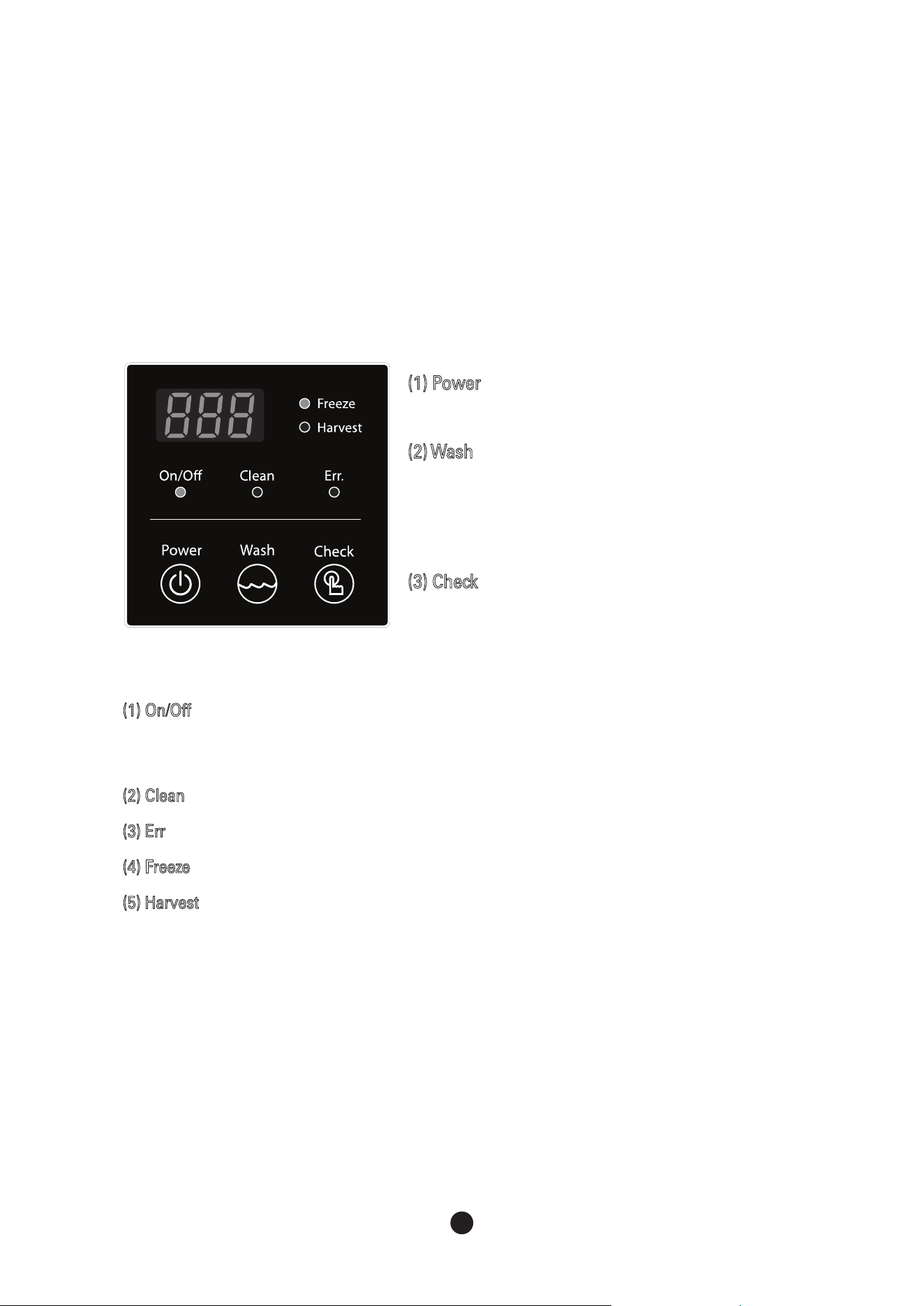
(1) Power
Push the button for 2 seconds to turn on/off.
(2) Wash
Use the button when cleaning the machine.
The instruction for Washing and Sanitation can be found in section
4.2 Interior Cleaning / Sanitizing Procedure and the label inside of
the front panel.
(3) Check
Only for service persons to check the status of the machine
(1) On/Off : shows power status in green.
If storage container is full of ice, orange light will appear.
If water level is too low, red light will appear.
(2) Clean : Green light will appear during washing mode.
(3) Err : Red light will appear if any problems occur during the machine operation.
(4) Freeze : Green light will appear during freezing cycle.
(5) Harvest : Green light will appear during harvest.
3. Operation
●
When turning off the unit during a testrun, please do not attempt to re-operate until at least
3 minutes later to protect the compressor.
●
If there is no water in the water tank, do not push"Wash" button to protect water pump seal.
●
While operating, please check for water leak son both the inside and outside pipe.
22
23
3.3 7-segment
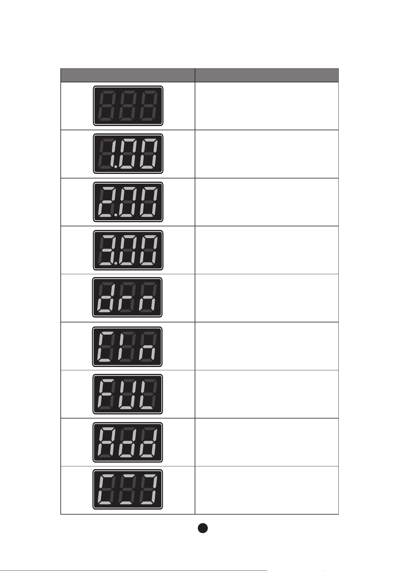
Display Status
Ready for cycle
1 = Water Supply Period
.00 = Elapsed time (x 10 sec)
2 = Harvesting Period
.00 = Elapsed time (min)
3 = Freezing Period
.00 = Elapsed time (min)
Drainage cycle
Wash mode
Ice machine is either cleaning or sanitizing.
Indicates when the bin is full of ice.
Wash mode
Indicates need to put detergent or sanitizer
into the machine.
Cleaning and saitization completed
(User has to press the button to remove
this sign)

22
23
1) Water supplying Cycle
Once power is on, wate supply valve opens to fill the water tank with water.
2) Harvesting Cycle
To remove ices made on the evaporator, water flow stops and it becomes hot. Then, ices are
released from the evaporator to the storage container. Once temperature sensor detects a certain
temperature, freezing cycle begins. Water continues to be supplied during the harvesting cycle.
3) Freezing Cycle
This is the process of making ices. Water is supplied to the surface of evaporator and it becomes
cold. As water keeps circulating, more and more ices are layered. This process is repeated until
water level sensor reaches low. Once it reaches low level, the harvest cycle starts.
4) Drainage Cycle
Residue or impurities will occur in the water tank during the repeating process of freezing and
harvesting cycles. Using the ice machine for a long time without draining may cause damage. After
a certain number of cycles, completely drain leftover water in the water tank by using water pump.
1) Maximum freezing time - 60min
To protect the ice machine, maximum freezing time is set to 60 minutes. When freezing cycle goes
over 60 minutes, it switches to the harvesting cycle. During the second freezing cycle, if time goes
over 60 minutes, machine stops and shows error code (E1) on the control panel with a beep sound.
2) Maximum harvesting time - 25min
The maximum harvesting time is 25 minutes. If time goes over 25 minutes, it automatically switches
into the freezing cycle. During the second harvesting cycle, if time goes over 25 minutes, error code
(E2) is shown on the contro panel with a beep sound.
3) High Temperature safety
If temperature outside the evaporator during freezing cycles goes over 140°F (60°C), machine stops
to protect the cycle and error code (E3) is shown on the control panel.
4) Low Water Safety
For protection of water pump, if water level is low after harvesting cycle, machine halts and error
code (E5) is shown on the control panel.
3.4 Operation Cycle
3.5 Safety
Ice machine is operated in accordance to the following process
24
25
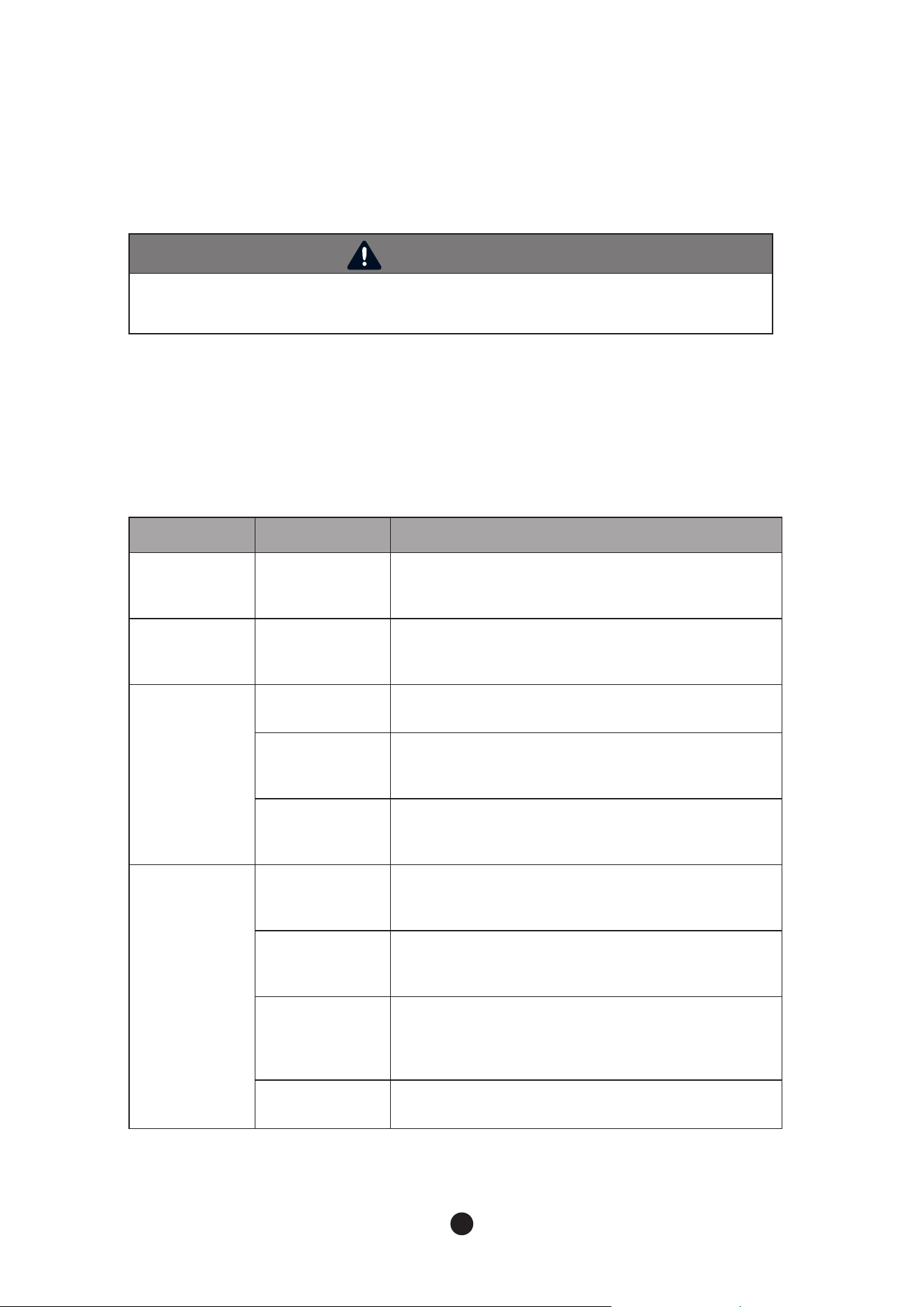
Code Problem Possible Cause Remarks
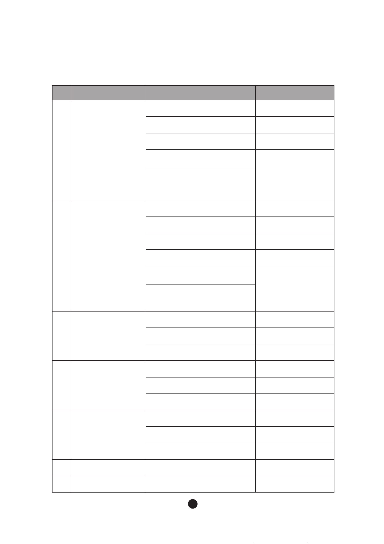
E1
Freezing error
(freezing time exceeds
60 min)
Refrigerant leaked or pipe blocked
Compressor not operating
Fan motor not operating
Ambient or water temperature too high
A/T : 45-100°F(7-38°C)
W/T : 45-90°F(7-32°C)
Voltage
115V :100-130 V
220V :208-230 V
Voltage too high or too low
E2
Harvesting error
(harvesting time
exceeds 25 min)
Refrigerant leaked or pipe blocked
Compressor not operating
Hot gas valve not operating
Evaporator temperature sensing error
Ambient or water temperature too low
A/T : 45-100°F(7-38°C)
W/T : 45-90°F(7-32°C)
Voltage
115V :100-130 V
220V : 208-230 V
Voltage too high or too low
E3
Evaporator temp too high
(temp > 140
°
For 60
°C
)
Water temperature too high
W/T : 45-90°F(7-32°C)
Sensor or connector defect
PCB defect
E4
No drainage when the
bin is full
Check water outlet hose
Check pump motor
Level Sensor not operating
E5
Water supply not enough
(water supply time
exceeds 4 min)
Float switch not operating
Water valve not operating
Water pressure too low
W/P:30-100psi
(206.8 ~ 689.4 kPa)
E6
Evaporator sensor error
Sensor short-circuit or disconnected
E7
PCB error
PCB program error
3.6 Error Code
24
25
4. Maintenance & Cleaning
●
Maintenance Period
4.1 Maintenance
WARNING
Ice machine must be maintained and cleaned based on schedule in this manual and the
cleaning label attached on each unit.
Refer to the following table for guidance on the maintenance period. The maintenance
period may be shorter than indicated depending on surrounding environment and hygiene
regulations of the installation area.
Period Area Details
Everyday Scoop
Clean scoop with food safe cleaner;
rinse with fresh water.
Every two
weeks
Air Filter
Clean with compressed air, or warm water and allow to
fully dry.
Every month
Water filter system Check proper water pressure and replace filter if needed
Ice machine
exterior
Clean with spot free water and soft cloth.
Bottom of ice
machine &bin door
Wipe it with a soft fabric
Every six
months
Ice machine & Ice
storage bin
Wash and sanitize according to the manual.
Please refer to '4.2 How to clean and sanitize'
Water Supply Inlet
Close the ice machine water supply line shut-off valve and drain
the water system. Clean the water supply inlet screen
Condenser
Inspect. Clean if necessary by using a brush or vacuum cleaner.
More frequent cleaning may be
required depending on location.
Water Hoses Inspect the water hoses and clean/replace if necessary.
26
27
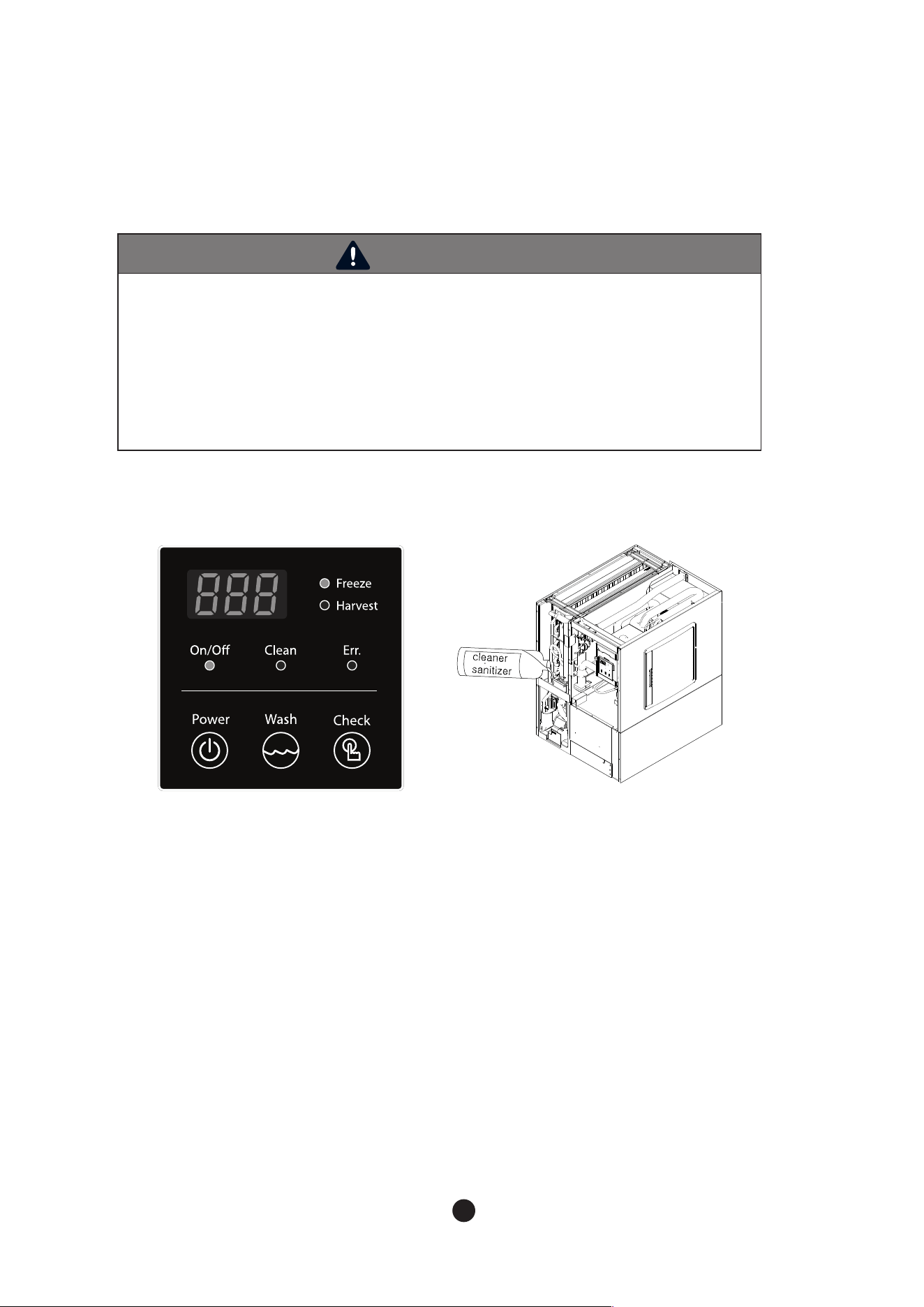
WARNING
- Use a detergent and sanitizer for ice machine, and follow the directions of those
products.
- During cleaning and sanitizing, wear rubber gloves and protective eye glasses
to protect eyes and skin.
- Keep detergent and sterilizer out of the reach of small children.
- Do not remove ices, made on evaporator, by force. It might cause damage to
the surface of evaporator.
- Do not remove ices on evaporator with a sharp ice pick.
The ice machine should be cleaned and sanitized every six months. Depending on the
installation condition, the machine may need more frequent cleaning and sanitizing.
4.2.1
Modular Cleaning Procedure
4.2. Interior Cleaning / Sanitizing Procedure
1) Press "power" to turn off ice machine. If machine is in freeze cycle, wait for harvest cycle to complete and turn
off ice machine by holding the“Power” button for 2 seconds.
2) Remove all ice from the storage bin.
3) Press the "Wash" button.
4) Machine will display “drn” on the control board and drain any remaining water in the water trough. If
machine doesn't detect any water, draincycle will be skipped and control board will move on to step 5.
5) Once all water has drained from machine, control board will read 'Add' and fill with fresh water for 3 minutes.
6) Remove front panel, and insulation Front (Fig 8). Add 16 oz. of Nu-Calgon ice machine cleaner into water
tank. (for 650Lb or lager machines, add 24 oz.) Machine will proceed to the clean cycle after a 60 second time
delay.
7) Control panel will now read 'Cln'.
8) Machine will circulate cleaning solution over evaporator for 30 minutes then drain.
9) After machine drains, water inlet valve will bring in fresh water for 3 minutes.
10) Pump will run for a 5-minute period to rinse remaining cleaning solution.
Fig 8

26
27
11) After 5 minutes, remaining water will drain.
12) For 30 minutes, ice machine repeats steps 9-11.
13) Once cleaning cycle is completed, will be displayed on control board.
14) Press "Power" to turn off ice machine.
15) Disassemble water level sensor, ice guide, water supply hose, spray tube, and spray guide referring to 4.2.3
Modular Prdoduct Disassembly
16) Mix 5 oz. of Nu-Calgon ice machine cleaner per gallon of water and use with a soft towel/sponge/nylon
brush to gently clean disassembled parts. plastic parts of evaporator, insulator front, and insulator top.
(Refer to 4.2.3 Modular Ice machine disassembly’)
17) Rinse all disassembled parts with fresh water.
18) Wash ice storage bin with remaining prepared cleaning solution from step 16. Rinse ice storage bin with
fresh water.
**WARNING- DO NOT CLEAN EXTERIOR OF MACHINE WITH CLEANING SOLUTION**
**If cleaning and sanitizing machine- move on to 4.2.2. Sanitizing; if cleaning only, proceed to step 19.
19) Reassemble ice machine. Hold and Press "Power" button for 2 seconds to turn on ice machine and resume
freezing cycle.
4.2.2 Modular Sanitizing Procedure
1) Press "power" to turn off ice machine. If machine is in freeze cycle, wait for harvest cycle to complete and
turn off ice machine by holding the “Power” button for 2 seconds.
2) Mix 2.5 oz. of Nu-Calgon ice machine sanitizer per gallon of water and use with a soft towel/sponge/nylon
brush to gently sanitize disassembled parts, plastic parts of evaporator, insulator front, and insulator top.
(see Fig 8)
3) Soak the disassembled parts from step 15 of cleaning instructions in prepared sanitizing solution for 5
minutes.
4) Sanitize ice machine food zones where evaporator is installed and storage bin with sanitizing solution.
5) Let sanitized parts dry completely.
6) Reassemble disassembled parts referring to 4.2.3 Modular Ice machine disassembly’. 7) Press the "Wash"
button.
8) Machine will display “drn” on the control board and drain any remaining water in the water trough. If
machine doesn't detect any water, drain cycle will be skipped and controlboard will move on to step 9.
9) Once all water has drained from machine, control board will read 'Add' and bring in fresh water for 3
minutes.
10) Remove front panel, and front insulation front (Panel 1 on Figure 8). Add 32 oz. of Nu- Calgon ice machine
sanitizer. (for 650Lb or lager machine add 48 oz.) Machine will proceed to the sanitizing cycle after a 60
second time delay.
11) Control panel will now read 'Cln'.
12) Machine will circulate sanitizing solution over evaporator for 30 minutes, then drain. 13) After machine
drains, water inlet valve will bring in fresh water for 3 minutes.
14) Pump will run for a 5-minute period to rinse remaining sanitizing solution.
15) After 5 minutes, remaining water will drain.
16) For 30 minutes, ice machine repeats steps 13-15.
17) Once sanitizing cycle is completed, will be displayed on control board.
18) Reassemble ice machine. Press "Power" button for 2 seconds to turn off ice machine. Press the “Power”
button for 2 seconds again to turn the ice machine on and resume the ice making cycle.
* Ice machine cleaner & sanitizer has to comply with 40 CFR §180.9403 or registered with the USEPA Office
of Pesticides Program, Antimicrobials Division as a food contact ice machine cleaner& sanitizer.
28
29
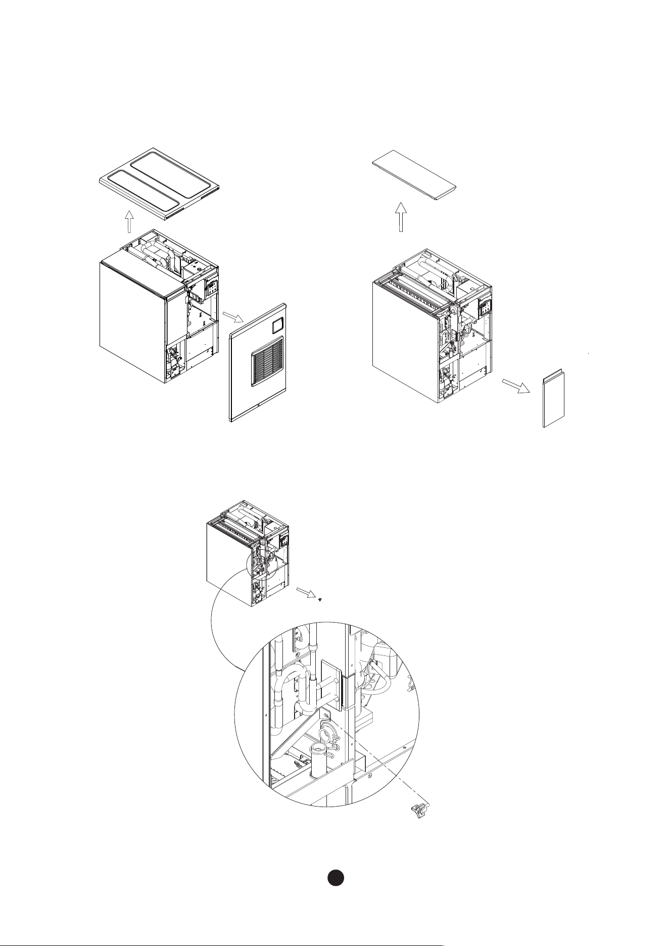
4.2.3 Product Disassembly
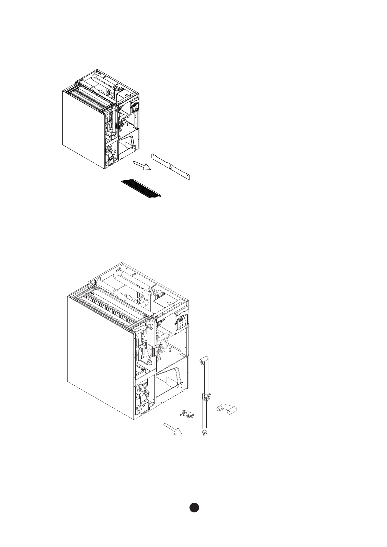
1~2. Detach insulation top and front after detaching cover top and cover front.
(Refer to 2.5 “Panel disassembly” for detailed instruction)
3. Release thumb screw in the cabinet by referring to above image.
Top Cover
Front Cover
Top Insulator
Front Insulator
Thumb Screw
28
29
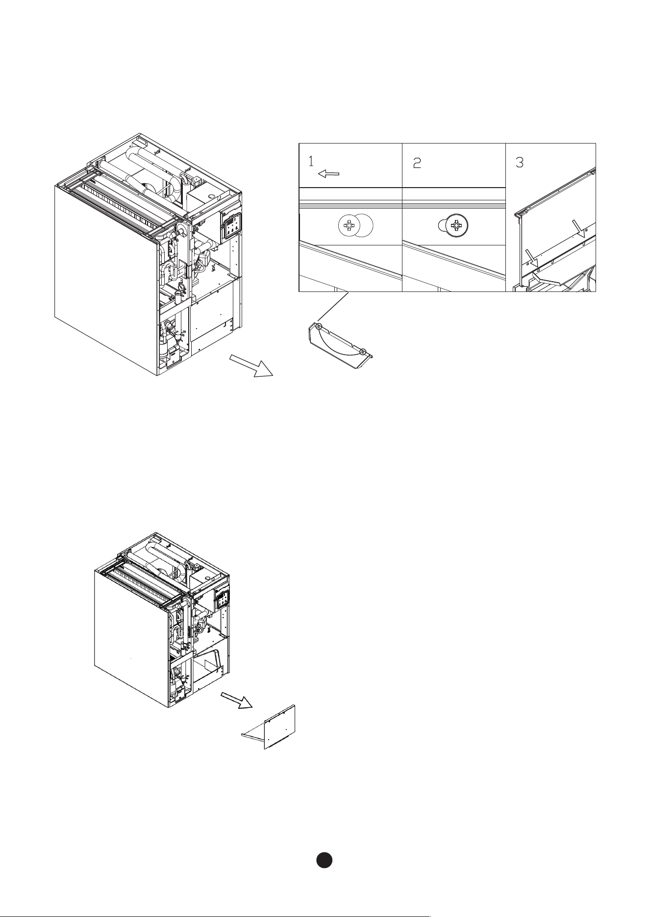
4.- Grip the Guide Ice Upper and push it to the rear.
- Pull it out through the left.
- Pull out the Guide Ice Upper
5. - Release the bolt fixed on the Ice Cover.
- Pull out the Ice Cover.
Ice Cover
Guide Ice Upper (only 300A)
30
31
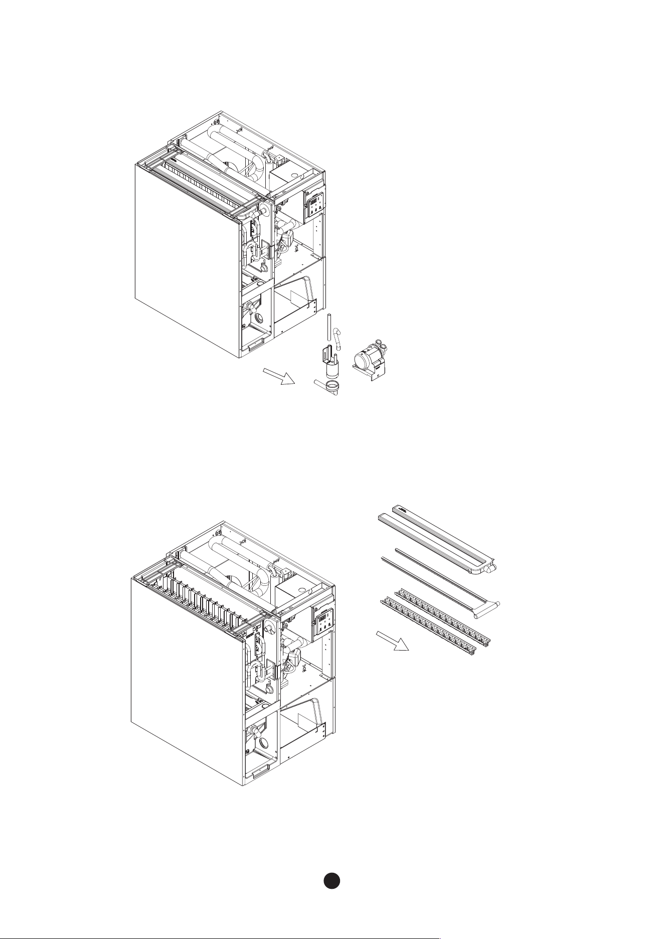
6. Pull out the parts to disassemble them in order of Water Cover and Guide Ice.
7. Disassemble the clamps to detach the hoses
Water Cover
Guide Ice
Hose
30
31
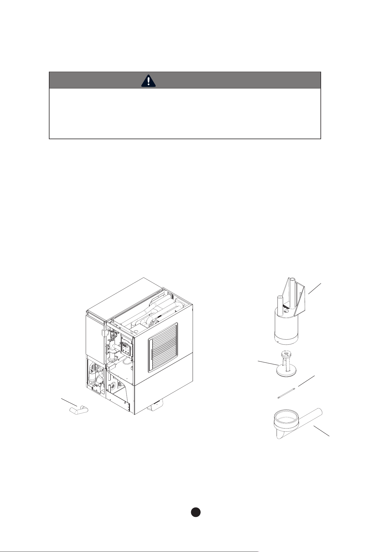
8. Unscrew the screws fixed on Level sensor and Pump motor and separate the Level sensor and
Pump Motor.
9. Pull out the parts in order of Spray Tube , Supply Tube , and Spray Guide to disassemble them.
Spray Tube
Supply Tube
Spray Guide
Pump Motor
32
33
WARNING
- Level sensor may not operate properly due to water condition or sediment inside of the
sensor.
For proper operation of Level sensor, clean the sediment inside of the sensor often.
- Level Sensor should be cleaned at least once a month.
(Recommended cleaning period can be shorter due to the condition of water.
4.3 Level Sensor Cleaning
1) Refer to “2.5 How to Remove Panel”, to separate the Ice Cover from body
2) In order to drain out water inside the cabinet completely, detach Pump Hose as shown in the mage.
3) Disassemble Level Sensor refer to “Front Cover” in the Removal and replacement chapter.
4) Separate the parts in order of Connector, Stopper, Float, and Body referring to image.
5) Wash contamination inside of Connector and Body.
6) Reassemble Level Sensor in reverse order.
7) Reassemble front panel.
Pump Hose
Body
Stopper
Level Sensor Connector
Float
Fig 7

32
33
4.4 Exterior Cleaning
4.5 Storage Container and Scoop
4.6 Air Filter
4.7 Condenser
To prevent corrosion, clean oil or dust in outer surface with cleaning towel or neutral detergent.
Clean storage container interior and scoop with neutral detergent. Wash with clean water afterwards.
Storage container is for ice only. Do not store any other material in the storage container.
Dust in the filter may decrease function of ice machine. Check the filter once every two weeks and if any
dust is found, clean by using warm water and neutral detergent. Dry the filter completely and reuse.
Check the condenser at least once a year and if cleaning is necessary, clean with vacuumand brush.
Cleaning interval may be shorter depending on the installation area.
4.8 How to Prepare for Long Term Storage
1) Wash and sanitize the ice machine.
2) Press “Power” button to turn off the ice machine.
3) Press “Power” and “Check” buttons for 2 seconds at the same time to drain remaining water inside of the
machine.
4) “drn” will display and once the remaining water level minimum level, the machine stop drain.
5) Disconnect the host connects water tank and pump motor to drain all remaining water inside of the unit.
Instruction can be found on 4.2.3 Modular Product Disassembly
6) Disconnect power code and lock water supply valve.
7) Disassemble water supply inlet and drain outlet at the back side of the machine.
8) Remove all remaining water inside of hoses installed in the machine, water supply inlet and drain outlet by
using air gun.
9) Nebulize sanitizer on the inside of the machine except for machine room and wait until they are completely
dried.
When not using the ice machine for a long period, remove all ices from the storage bin and drain all
remaining water in the water tank. Clean and dry the storage bin. Also, remove all the water from the
ice machine to prevent the water supply hose from getting frozen under low temperature during winter.
Turn off the product until the temperature is warm.
MEMO
34
35
MEMO
34
35

BLUE AIR FSE, LLC.
Gardena, CA 90248
Tel: 866.677.8500 / 310.808.0102
Fax: 310.808.0242 / 310.808.0262
Visit us our website at www.blueairfse.com

