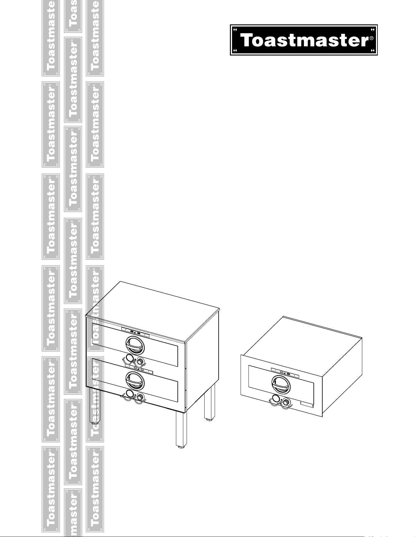
HOT FOOD SERVERS
FREE STANDING MODELS
3A81D
3B82D, 3B84D
3C84D, 3D8XD
3B84D
BUILT-IN MODELS
3A20A, 3A80A
3B20A, 3B80A,3B84A
3C80A, 3C84A
Installation and
Operation
Instructions
2M-3102301, REV E (10-22)
IL2087
3A20A
2
2
SAFETY SYMBOLS
These symbols are intended to alert the user to the presence of
important operating and maintenance instructions in the manual
accompanying the appliance.
CAUTION WARNING
RETAIN THIS MANUAL FOR FUTURE REFERENCE
NOTICE
Using any part other than genuine Toastmaster factory supplied parts relieves the
manufacturer of all liability.
without notice. Such revisions do not entitle the buyer to corresponding changes,
improvements, additions or replacements for previously purchased
equipment.
Due to periodic changes in designs, methods, procedures, policies and
without notice. While Toastmaster exercises good faith efforts to provide
information that is accurate, we are not responsible for errors or omissions
in information provided or conclusions reached as a result of using the
connection with such use.
MAINTENANCE AND REPAIRS
Contact your local authorized service agent for service or required maintenance.
Please record the model number, serial number, voltage and purchase date in the area below and have it
ready when you call to ensure a faster service.
Authorized Service Agent Listing
Reference the listing provided with the unit
or
for an updated listing go to:
Model No.
Serial No.
Voltage
Website: www.toastmastercorp.com
(800) 264-7827
Purchase Date
E-mail
Telephone:
The Service Help Desk
Business 8:00 am to 4:30 p.m. Central Standard Time
Hours:
Telephone:
(800) 264-7827
www.toastmastercorp.com
Fax:
E-mail
Website:
Mailing Address: STAR MANUFACTURING INTERNATIONAL INC.
265 Hobson Street
Smithville, TN 37166
U.S.A
1
TABLE OF CONTENTS
Page
Electrical Specications ................................ 1
Specications .......................................2
Features & Descriptions ...............................3
Accessories .........................................4
Installation
Inspection for Shipping Damage ....................4
Unpacking .....................................4
Installation of Free-Standing Models .................5
Installation of Built-In Units ........................6
Initial Start-up ...................................7
Operation
Location of Controls .............................. 8
Function of Controls ..............................8
Operation ......................................8
Shutdown ...................................... 9
Pre-heating ....................................9
Capacity Per Pan ................................ 9
Recommended Temp & Humidity Setting .............10
Daily Cleaning ................................ 10-11
Clean & Lubricate ...............................11
Warranty ...........................................13
Exploded View & Parts List
Single Drawer Units ............................ 14-16
Two, Three & Four Drawer, Single Controls ......... 18-21
Two, Three & Four Drawer, Individual Controls ....... 22-24
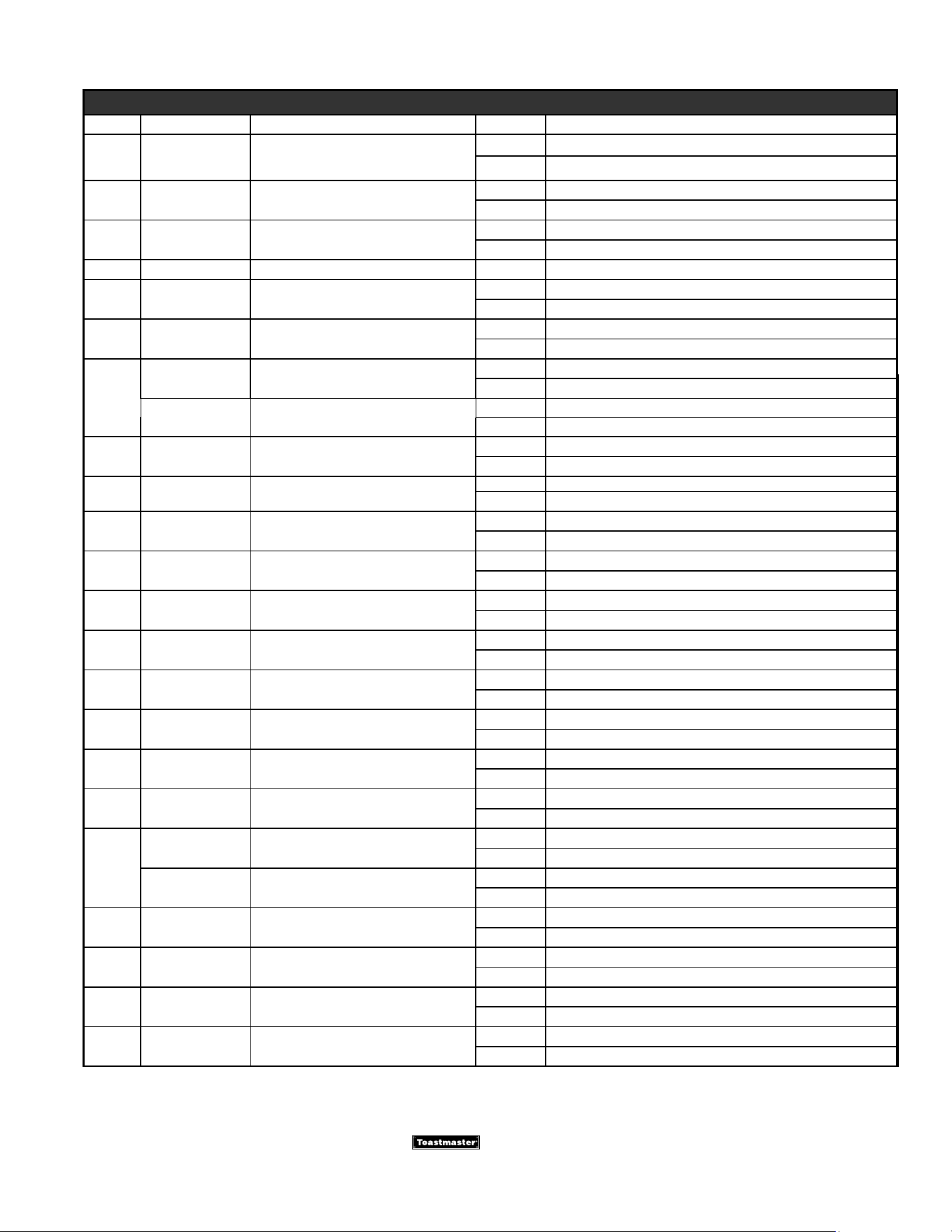
ELECTRICAL SPECIFICATIONS
ELECTRICAL SPECIFICATIONS
Model No Voltage Watts Phasee Hz Power Cord
7C-3A20AT09-120 3A20A 120 .45 KW 1 50/60
7C-3A80AT09-120 3A80A 120 .45 KW 1 50/60
7C-3A80AT72-240 3A80A 240 .4/.54 KW 1 50/60
7C-3A80AWC-120V 3A80A 120 .45 KW 1 50/60 5-15P
7C-3A81D-120KFC 3A81D-KFC 120 .45 KW 1 50/60
7C-3A81DT09-120 3A81D 120 .45 KW 1 50/60
7C-3A81DT72-240 3A81D 208/240 .45/.54 KW 1 50/60
7C-3B20AT09-120 3B20A 120 1.0 KW 1 50/60
7C-3B20AT72-240 3B20A 208/240 .9/1.2 KW 1 50/60
7C-3B80AT09-120 3B80A 120 1.0 KW 1 50/60
7C-3B80AT72-240 3B80A 208/240 .9/1.2 KW 1 50/60
7C-3B80AWC-120V 3B80A 120 1.0 KW 1 50/60 5-15P
7C-3B82DT09-CFA 3D82D 120V 1.0KW 1 50/60 5-15P
7C-3B84AT09-120 3B84A 120 .9 KW 1 50/60
7C-3B84AT72-240 / -SA 3B84A 208/240 .85/.98 KW 1 50/60
7C-3B84DT09-120 3B84D 120 .9 KW 1 50/60
7C-3B84DT09-KFC 3B84D-KFC 120 .9 KW 1 50/60
7C-3B84DT72-240 3B84D 208/240 .85/.98 KW 1 50/60
7C-3C80AT09-120 3C80A 120 1.35 KW 1 50/60
7C-3C80AT72-240 3C80A 208/240 1.22/1.6 KW 1 50/60
7C-3C84AT09-120 3C84A 120V
7C-3C84AT72-240 3C84D 208/240 1.28/1.47 KW 1 50/60
7C-3C84DT09-120 3C84D 120 1.35 KW 1 50/60
7C-3C84DT72-240 3B84D 208/240 .85/.98 KW 1 50/60
7C-3D8XDT09-120 3D8XD 120 1.35 KW 1 50/60
7C-3D8XDT72-240 3D8XD 208/240 1.22/1.6 KW 1 50/60
2
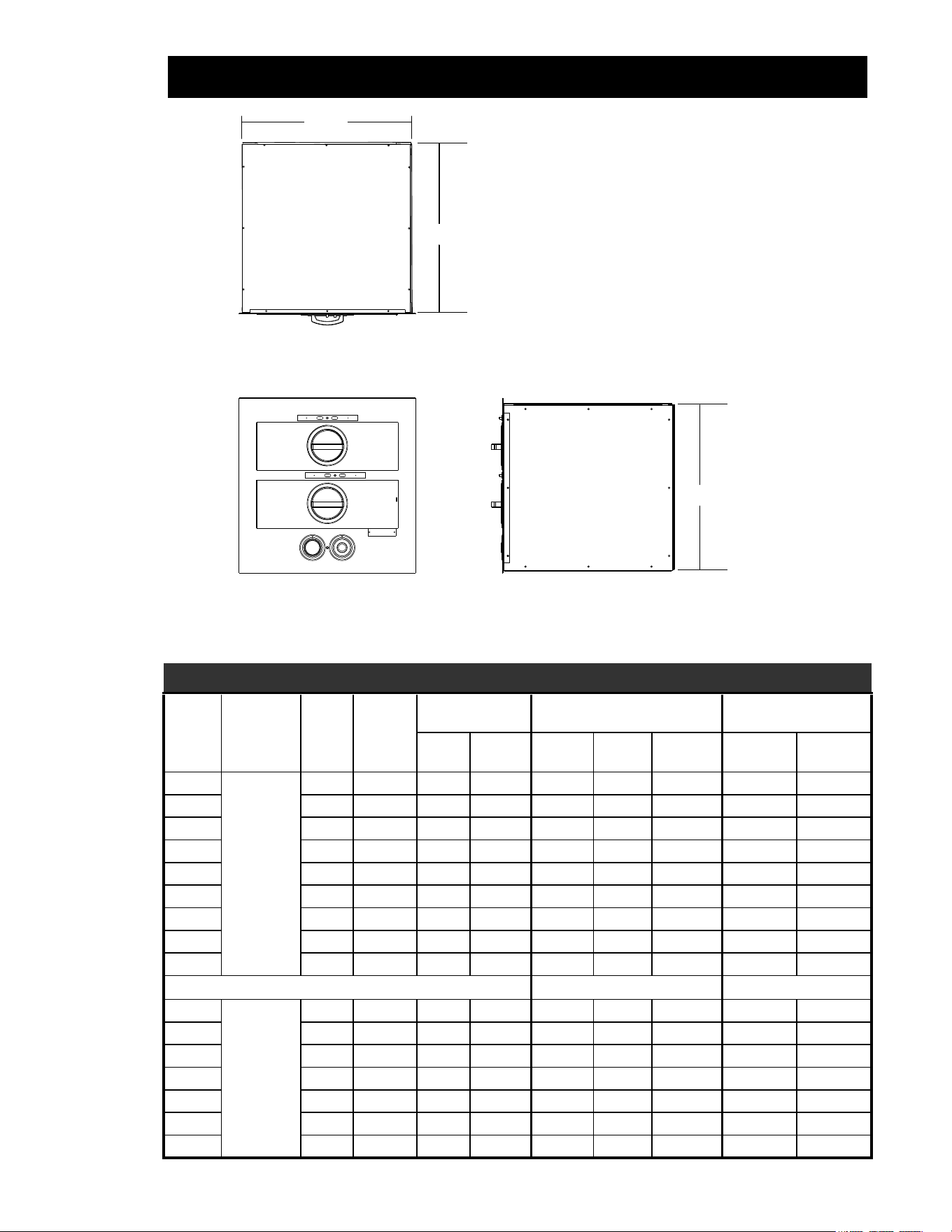
Height
Front View Side View
Top View
Width
Depth
IL2088
SPECIFICATIONS
MODEL CHART
Model
Built-In /
Free Standing
Drawers
Individual
Drawer
Control
Preheat Times
(minutes)
Dimensions Weight
150°F
(65°C)
175°F
(79°C)
“W” “D” “H” w/o legs Installed Shipped
3A81D
Free Standing
1 YES 18.8 26.2 29 1/16 20 3/8 11 84 lbs 94 lbs
3A20D 1 YES 18.8 26.2 24 1/16 22 9/16 12 1/4 84 lbs 94 lbs
3A21D 1 YES 18.8 26.2 24 1/16 22 9/16 12 1/4 84 lbs 94 lbs
3B22D 2 NO 17.2 24.8 23 1/16 24 1/4 22 1/8 129 lbs 144 lbs
3B82D 2 NO 18.8 26.2 29 1/16 20 5/16 21 1/8 120 lbs 139 lbs
3B84D 2 YES 18.8 26.2 29 1/8 20 7/16 21 5/8 120 lbs 139 lbs
3C8XD 3 NO 20.6 28.2 29 1/16 20 5/16 28 3/4 201 lbs 229 lbs
3C84D 3 YES 18.8 26.2 29 1/8 20 7/16 32 5/16 201 lbs 229 lbs
3D8XD 4 NO 22.3 29.7 29 1/16 20 5/8 36 5/16 237 lbs 252 lbs
Body Dimensions
3A20A
Built-In
1 YES 18.8 25.8 23 1/16 23 11 1/4 70 lbs 82 lbs
3A80A 1 YES 18.8 26.2 29 1/16 19 1/8 11 72 lbs 84 lbs
3B20A 2 NO 17.2 21.8 23 1/16 23 22 1/2 120 lbs 138 lbs
3B80A 2 NO 18.8 26.2 29 1/16 19 1/4 21 1/2 125 lbs 144 lbs
3B84A 2 YES 18.8 26.2 29 1/16 19 1/4 21 3/4 125 lbs 144 lbs
3C80A 3 NO 20.6 28.2 29 1/16 19 1/4 29 5/16 171 lbs 186 lbs
3C84A 3 YES 18.8 26.2 29 1/16 19 1/4 32 1/2 206 lbs 228 lbs
3
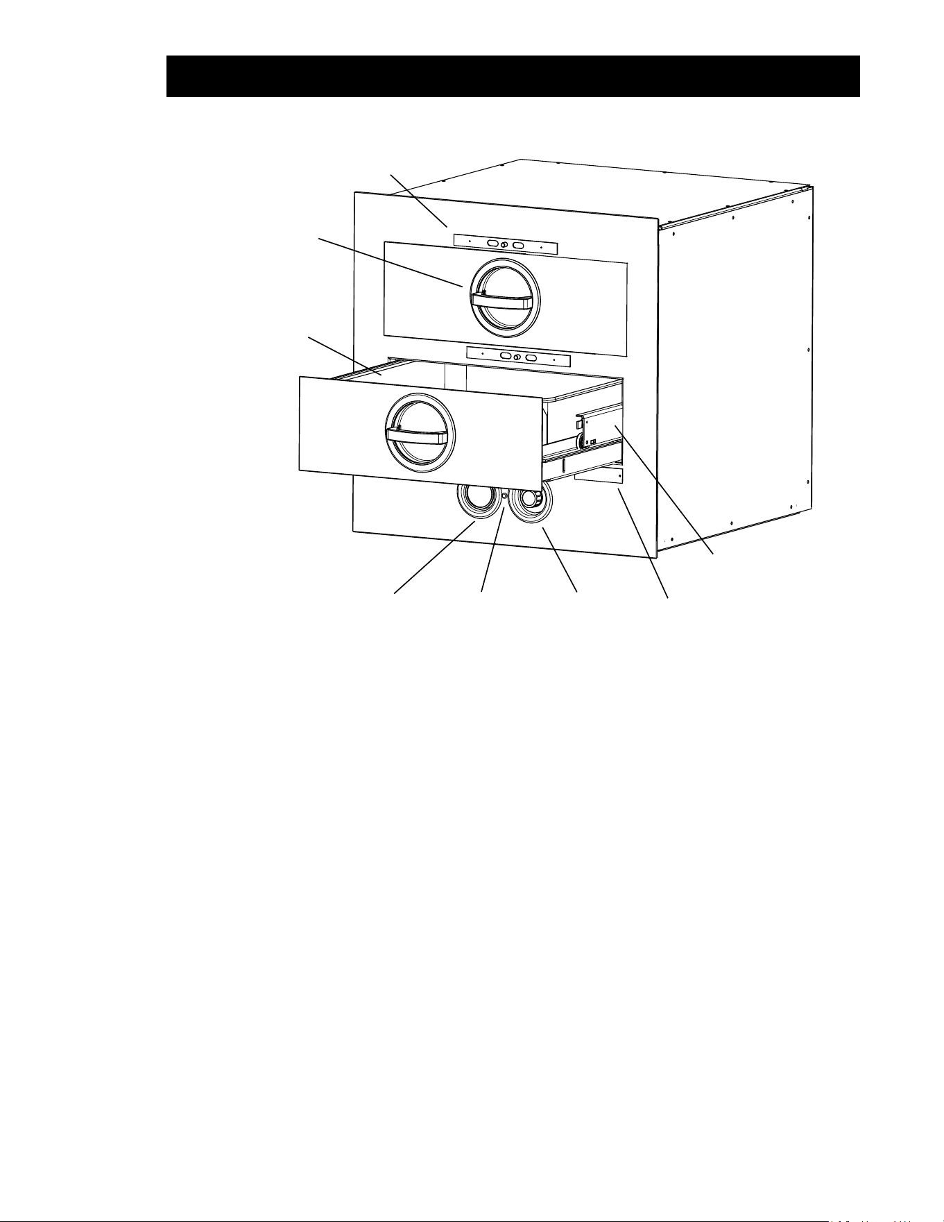
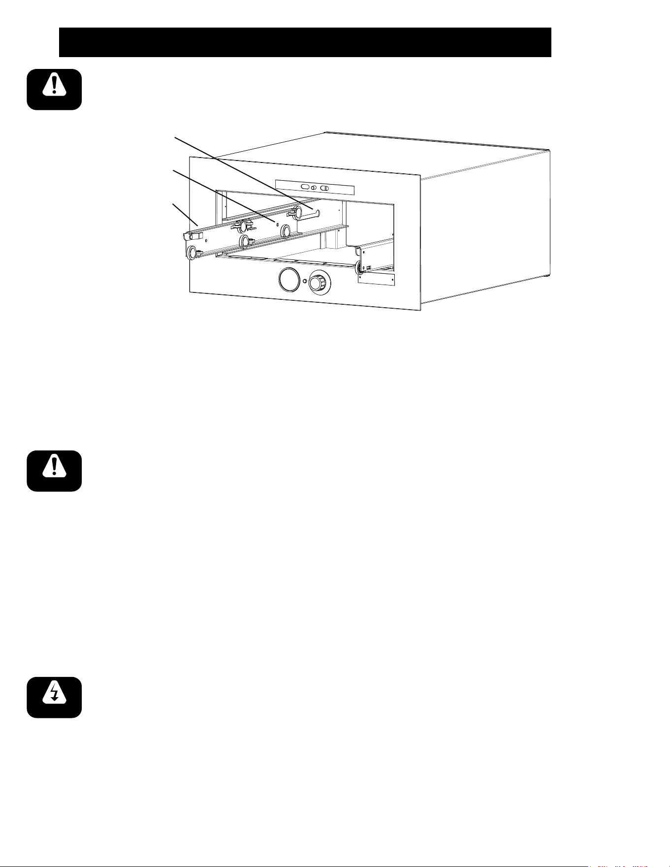
Moisture
Control Adjustment
Thermostat Knob
(Adj 100°F to 200°F)
Thermometer Indicator
Light
Handle Latching
Mechanism
Third Member
Drawer Rail
Drawer
Pan Insert
Nameplate
IL2089
FEATURES & DESCRIPTIONS
COMPONENT LOCATION & FUNCTION
Toastmaster Hot Food Servers are heated drawer-type cabinets designed to HOLD food cooked in
advance at serving temperature and proper moisture content.
Thermostat: The thermostat is graduated from 0 to 10 which makes is adjustable
from 100°F to 200°F (38°C to 93°C) holding temperature. Some
models are equipped with separate thermostat for each drawer. Refer
to Specications on the previous page.
Thermometer: The thermometer is used to visually check if the holding temperature is
at the desired setting. Chicken, beef, ribs, sh, potatoes, vegetables
and sauces can be held at temperatures with condence because you
can see that the actual holding temperature is safe. The thermometer
will tell at a glace if the holding temperature is high enough to retard
dangerous bacteria growth and low enough to prevent overcooking and
drying out food.
Note: On models with one drawer and on models with individual temperature controls for each drawer
the thermostat knob and thermometer are protected with either a wire guard, or the are recessed into the
front panel.
Moisture Control: The moisture control consist of a slide which is used to control the
amount of moisture allowed to escape form the foods being held.
Indicator Light: The light will illuminate when the unit is calling for heat and will shut off
when it has reached the set temperature.
4
INSTALLATION
INSTALLATION
A. Inspect for Shipping Damage
All shipping containers should be examined for damage before and during
unloading. This equipment was carefully inspected and packaged at
the factory. The freight carrier has assumed responsibility for its safe
transit and delivery. If equipment is received in damage condition, either
apparent of concealed, a claim must be made with the delivery carrier.
1. Apparent Damage or Loss - If damage or loss is apparent it must be
noted on the freight bill or express receipt at the time of delivery, and
it must be signed by the carrier’s agent (driver). If this is not done, the
carrier may refuse the claim. The carrier will supply the necessary claim forms.
2. Concealed Damage or Loss - If damage or loss is NOT apparent until after equipment is
unpacked, a request for inspection of concealed damage must be made with carrier within
15 days. The carrier will make an inspection and will supply necessary claim forms. Be
certain to retain all contents plus external and internal packaging materials for inspection.
B. Unpacking Hot Food Server
1. Open carton and remove it from around hot food server, then remove the empty carton from
the area.
2. Remove all tape from unit and set food server on its side on three 2x4’s (as shown in Figure
2-1) so the packing skid attached to the bottom of the unit is off the ground.
WARNING: DO NOT set the unit on its back, damage could be occur to the power cord or
conduit. Place unit on its side.
3. Remove 4 bolts attaching skid to bottom of unit.
DESCRIPTION continued
Accessories
3 & 4 Drawer Free Standing Models:
7C-3L6 Square legs 6” high, stainless steel, set of 4, leveling adj. up to 3/4”
7C-3L9 Square legs 9” high, stainless steel, set of 4, leveling adj. up to 3/4”
7C-3L12 Square legs 12” high, stainless steel, set of 4, leveling adj. up to 3/4”
7C-3L15 Square legs 15” high, stainless steel, set of 4, leveling adj. up to 3/4”
7C-3M3 Casters, 3”, set of four (swivel without brakes) adds 4-1/4” to unit height
7C-3M4 Casters, 3”, set of four (two swivel/lock, two xed), adds 4-1/4” to unit height
2 Drawer Free Standing Models:
7C-3M338STSB Casters, 3” set of four swivel (two with brakes), 360lbs. Load capacity
5
C. Installation of Free-Standing Models
1. Counter top Models 3B22D, 3A81D, 3A20D, 3A21D , 3B82D AND 3B84D.
a. Countertop models are shipped with a set of four 4”(102mm) adjustable legs or an
optional set of 4 casters (see Accessories Chart on previous page) can be ordered.
Screw the legs or casters into the threaded holes in the corners of the unit bottom.
b. Hot food servers with legs can be set on the oor or on the counter. Units with
casters can only be set on the oor. Do not set the hot food server with casters
on a counter top.
c. Level unit with legs by turning the hexagonal adjustment feet located at the bottom
of the legs.
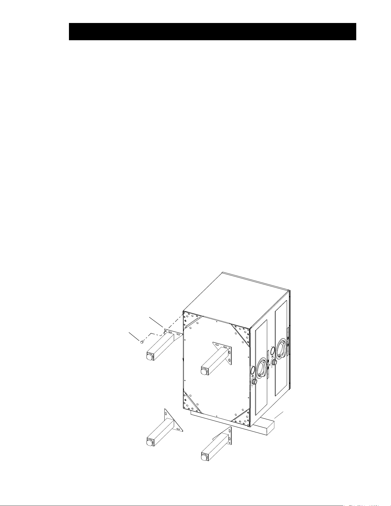
2. Floor Models 3B82DT, 3C8XD, 3C84D AND 3D8XD are usually installed as oor models
due to their size. One of the available leg or caster accessory kits must be used in the
installation.
a. Leg Installation using accessory kit (see chart for available leg or caster accessories,
sold separately)
Locate and open the accessory leg kit and the hardware package included with it.
With the hot food server on it side and the 2x4’s still positioned under the unit, align
the square corner of a leg ange with a corner of the unit. Attach the leg ange using
5 of the bolts furnished. Refer to gure 2-2.
Repeat for remaining three legs.
Carefully set unit upright, using a level, level the server by turning the adjustable feet.
b. Caster Installation using accessory kit (see chart for available leg or caster
accessories, sold separately)
The casters kits are installed the same as the leg kits above, except 2 of the casters
are xed and should be installed at one end or at the rear. The other 2 swivel casters
with brakes are installed opposite the xed casters.
LEG
2” x 4”
BOLT
IL2094
Fig. 2-1, Leg / Caster Installation
INSTALLATION continued
6
3. Electrical Connections:
FREE STANDING UNITS: All free standing hot food servers are quipped with a factory installed 36”
(914mm) cord and plug.
• 120V models: Plug conforms to NEMA Standard 5-15P
• 208/240V models: Plug conforms to NEMA Standard 6-15P
BUILT-IN UNITS: Most units are provided with a 48” exible metal conduit for electrical connections
(see electrical specications for specics).
D. Installation of Built-In Units:
All of these units are true built-in models and are designed to be installed into the front face of a counter xture.
Front of units extends beyond the body to form a self-trimming ange that covers the cut out in the xture.
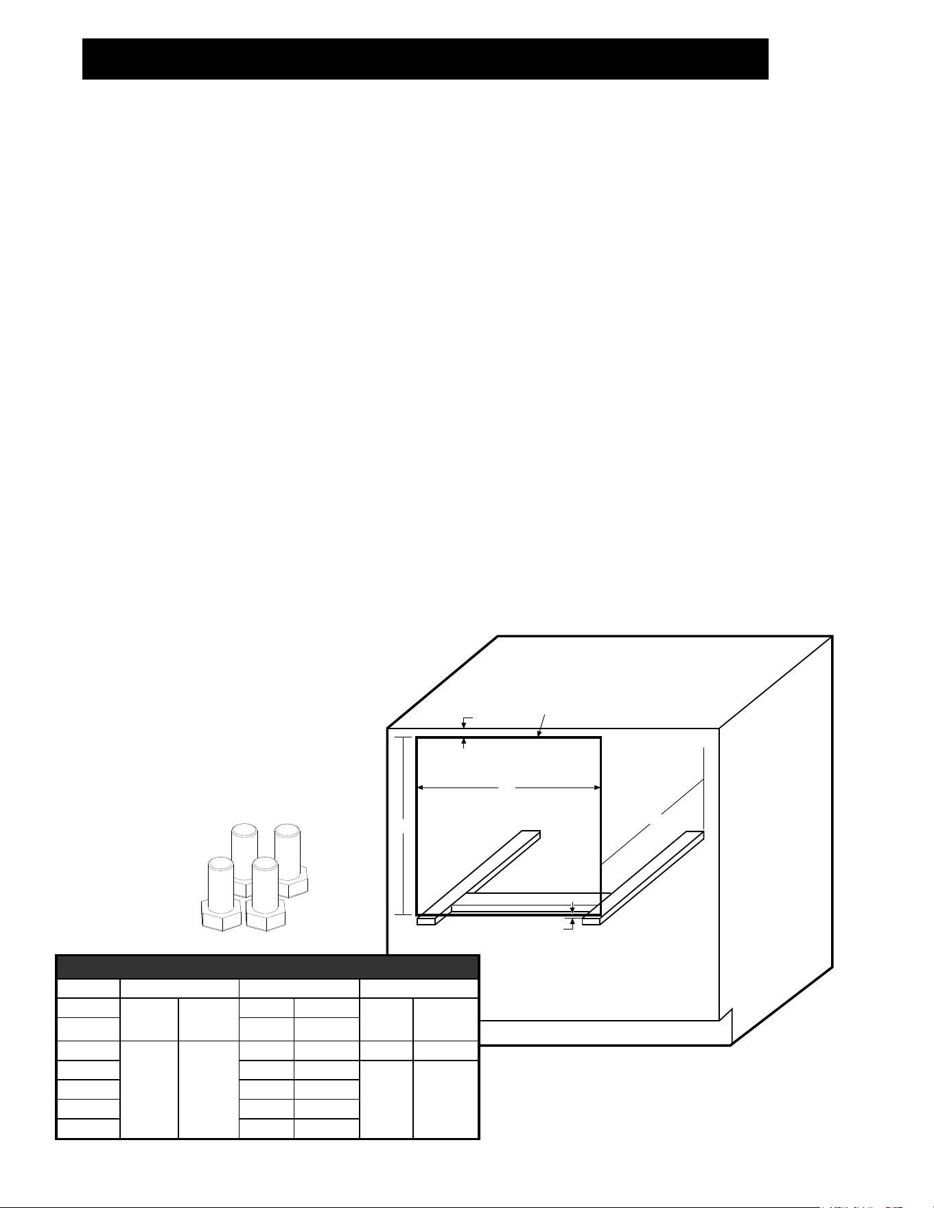
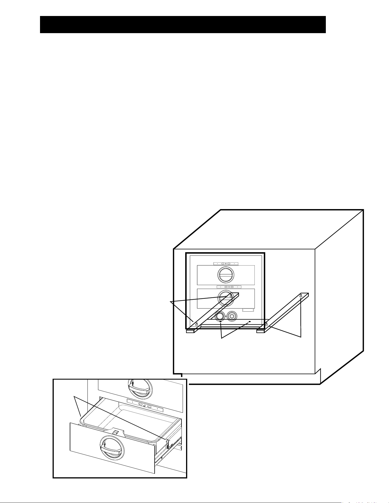
1. Cabinet Cut Out and Support. Cut out the face of the counter xture according to the drawing that is
provided with your hot food server. Figure 2-5 can also be used for the cut out drawing of your model
number. As shown in the drawing allow 1/2” (13mm) minimum cabinet face material above top of cut out
opening. This allows unobstructed seating of hot food server ange.
Be sure counter xture has adequate depth from front face to inside of back to accept the hot food server.
Minimum depths are shown for each model in Figure 2-5.
a. The hot food server body must be supported from the bottom. This can be accomplished by
installing metal support angles of wooden support blocks as shown in Figure 2-5. The supports
are not supplied and must be furnished using a suitable strength metal or wood. The top surface
of these supports must be 1/16” (3mm) below the bottom edge of the face cut out. A metal or
wood crossbrace approximately 2-1/2” (64mm) wide should be securely mounted between the
supports as shown. The center line of the crossbrace must be 4” (102mm) from the face of the
cut out and its top surface must be ush with the side supports.
b. An alternate support method is to install a solid at platform in lieu of the side supports and
crossbrace. The top surface of the platform must be 1/16” (3mm) below the bottom edge of the
cut out.
INSTALLATION continued
B
A
C
1/2” Minimum
Cut Opening for
Hot Food Server
1/2” Minimum
IL2090-01
Figure 2-5, Cabinet Mounting
BUILT-IN MODELS OPENING DIMENSIONS
Model “A” Width “B” Height “C” Depth
3A20A
23 3/8” 594 mm
11 1/2” 292 mm
24 1/2” 622 mm
3B20A 22 3/4” 578 mm
3A80A
29 3/8” 746 mm
11 1/4’ 286 mm 20 5/8” 524 mm
3B80A 21 3/4” 552 mm
20 3/4” 527 mm
3C80A 29 1/2” 749 mm
3B84A 22” 559 mm
3C84A 32 3/4” 832 mm
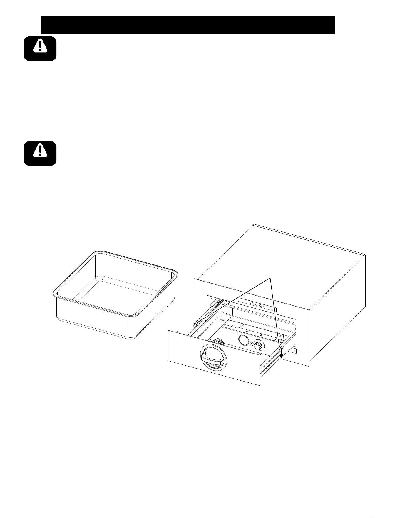
2. Install Leveling Feet (shown
below). Open the top drawer
and remove the small cloth bag
containing four hex head cap
screws & two mounting screws.
Thread these four screws hand
tight up into the four holes in
the bottom of the unit. Refer to
2-6.
IL2100
Right: Leveling Feet for
Built-in Units.
(pn: 2C-1513D8805)
7
3. Electrical Connection. All electrical connections required for this unit must be performed by a certied
electrician. Built-in models are equipped with a 3/4” (19mm) diameter x 4ft. (122cm) long exible conduit
containing power lead pigtails and a ground wire. It is necessary that this conduit and the wiring leads
connect at a junction box in accordance with local codes. Be sure to check the data plate on the front of
the unit to be sure the power supply is correct. 115V units operate on voltage ranging from 110V to 125V.
220V units operate on voltage ranging from 208V to 240V.
4. Mount Unit in Cabinet.
a. Remove the drawer(s) from the unit, pull the drawer(s) out to the stop. Grasp the entire drawer
assembly at the sides as if to lift it and locate your thumbs on the tabs of the drawer slide (gure
2-7). Press down on these tabs with your thumbs and simultaneously pull out on the drawer. Set
drawer assembly aside.
b. Lift the unit form both sides and start its backside into the cut out. Push back until the trim ange
meets the face of the xture.
c. Place a level on the oor of the unit and check from side to side and front to back. If adjustments
are necessary, slide the entire unit out of the xture and adjust the leveling feet as required.
d. Secure the unit into position after leveling. There are two holes in the unit bottom for this purpose
(See Figure 2-6). Place a drill bit down through these two holes and bore two pilot holes into the
crossbrace beneath. Tighten a pair of at head sheet metal screws down through these holes
and into the crossbrace. The unit is now installed.
e. Replace the drawers. NOTE: The drawers of multiple drawer units are individually identied
(ex: “TOP”, “2” AND “3”). They should be reinstalled in their respective positions.
E. Initial Start-up
1. Turn on the branch line circuit
breaker
2. Set the thermostat control dial
at “10” the indiactor light will
come on indicating that unit is
calling for heat.
3. After a few minutes have
elapsed, open a drawer and
check that the unit is heating.
NOTE: If your unit is equipped with
a separate thermostat for each
drawer, complete Steps 2 & 3
for each drawer individually.
4. If unit fails to heat, recheck to
be sure circuit breakers are
on and electrical connections
are properly made. If it still
fails to heat, call a Toastmaster
Authorized Service Agent.
INSTALLATION continued
Bolts used as
leveling feet
Bolts used as
leveling feet
Drill starter holes and attach
hot food server to support through
these two holes.
Use flat head screws.
IL2090-02
Drawer
Release Tabs
IL2101
Above: Figure 2-6, Cabinet Mounting
Left: Figure 2-7, Drawer Release Tabs

8
OPERATION
A. Location of Controls
The following information provides a basic description of the hot food server components, their location and function
they perform.
B. Function of Controls
Hot food server models are either equipped with one set of controls for the complete unit of a separate set of controls
for each drawer. Units with one set of controls have a thermostat control, indicator light and thermometer located
below the drawer(s). Units with separate drawer controls have them under each drawer.
1. Thermostat Control Knob - The thermostat control knob is used to set the temperature to your requirements.
The control knob is graduated from “0” to “10” with “OFF” position. The maximum temperature setting is 10
(200°F [93°C]), the minimum temperature setting is 0 (100°F [38°C]).
2. Indicator Light - An indicator light cycles on and off as the thermostat calls for heat.
3. Thermometer - The thermometer indicates the actual holding temperature within the unit.
4. Moisture Control - Hot food servers operate on a principle of holding food at proper and safe temperatures
and with proper moisture content. Because hot food servers produce dry heat, moisture loss from the food
must be controlled. The moisture control allows the operator to control the rate at which the natural moisture
of the food escapes.
Slide the moisture control for the desired opening:
Crisp: Slide is fully opened to allow rapid escape of moisture so crisp foods placed in the
hot food server will not get soggy.
Partially Open: Adjust slide for the desired amount of moisture retention.
Moist: Slide is fully closed to retain all of the moisture in the food.
C. Operation
1. Turn the main power disconnect switch (circuit breaker) ON.
2. Turn the thermostat control knob to the desired setting. Allow the unit to preheat for the time shown in the
following chart. The indicator light will cycle ON and OFF as it heats.
3. Read the thermometer after the preheat time has elapsed. If the indicated temperature is above or below
the desired (set) temperature adjust the thermostat up of down unit the desired holding temperature is
reached.
4. Place cooked food into hot food server drawer(s) WHILE HOT. Do not allow to cool.
5. Close drawer and set moisture control slide to the desired position appropriate for the food being held. Refer
“FUNCTION CONTROLS” for moisture control settings.
6. Open drawers as required to remove and/or replenish food.
IMPORTANT: When holding bread and rolls it is important to rotate product. Rolls already in the drawer should
be moved to the front and rolls being added should be placed at the rear.
Rolls that have been heated once and then cooled have lost most of their moisture while setting in the open air,
they can not be reheated with satisfactory results.
9
OPERATION continued
D. Shutdown
1. Turn the thermostat control knob to “OFF”.
E. Pre-heating
Model
Preheat Time in Minutes
150°F (66°C) 175°F (79°C)
3A21D
18.5 25.83A20A
3A20D
3B20A
17.2
21.8
3B22D 24.8
3A80A/3A81D
18.8 26.2
3B80A/3B82D
3B84A/3B84D
3C84A/3C84D
3C80A/3C8XD 20.6 28.2
3D8XD 22.3 29.7
CAPACITY PER PAN
Model No
Baked Potatoes Vegetables Ribs Hamburger Buns Dinner Rolls
(120 count) (#10 Can) (lbs.) (doz.) (doz.)
3A20A, 3B20A, 3B22D, 3A20D, 3A21D 35 7 25 5 6
3A80A, 3B80A, 3C80A, 3A81D, 3B82D, 3C8XD, 3D8XD
40 8 30 6-1/2 7
3B84A, 3C84A, 3B84D, 3C84D
10
OPERATION continued
G. Recommended Temperature & Humidity Settings
H. Daily Cleaning
CAUTION: BEFORE CLEANING BE SURE TO TURN OFF THE HOT FOOD SERVER’S MAIN DISCONNECT
SWITCH.
1. Drawer Pans
a. Open the drawer(s) and lift the pan(s) out.
b. Empty contents of pan and wash pan in hot soapy water.
c. Rinse with hot water and let air dry.
or
d. If desired pan can be pre-rinsed and then run through dishwasher and air dried.
2. Exterior Surface (Stainless Steel)
a. Wash with a damp cloth or sponge wrung out of detergent and hot water solution.
b. Rinse with a damp cloth or sponge wrung out of hot clean water.
c. Dry and polish with a soft cloth
or
d. Clean the exterior using a good stainless steel cleaner/polish. Spray on and wipe off.
e. For best results always polish in the direction of the nish grain of the metal.
Recommended Temperature and Humidity Settings
Temperature Humidity
Soft Rolls: Clover Leaf, Cinnamon Rolls, Corn Bread, Doughnuts,
Gingerbread, Hamburger & Frankfurter Buns, Mufns, Parker House, Soft
Oval and Sweet Rolls.
150°F to 175°F
Moist
(66°C to 79°C)
Hard Rolls: French, Kaiser, Swiss & Poppy Seed Rolls and Salt Sticks
150°F to 175°F
3/4 to Crisp
(66°C to 79°C)
Vegetables: Asparagus, Beans, Beets, Boiled or Mashed Potatoes,
Braised Celery, Broccoli, Brussel Sprouts, Carrots, Corn Dutch Potato
Salad, Peas, Spinach & Tomatoes
175°F to 185°F
Moist
(79°C to 85°C)
Meat, Fish & Eggs: Bacon, Baked Fish, Barbecued Spareribs,
Beef or Pork Roasts, Chicken Croquettes, Chicken-Whole or Sliced,
Frankfurters, Ground Steak Patties, Ham, Hash, Lamb and Pork Chops,
Liver, Lobster and Shrimp, Meat Loaf, Roast Duck, Sausage, Scrambled
Eggs, Swiss Steak and Veal Cutlets
165°F to 185°F
Moist
(74°C to 85°C)
Casserole Dishes, Chicken Pot Pie, Cod Fish Cakes, Fried Chicken, Fried
Fish, Hamburgers and Scallops
150°F to 175°F
Moist
(66°C to 79°C)
Pies & Desserts: Apple Brown Betty, Plum Pudding and Steamed
Raisin Puddings
160°F to 185°F
Moist
(71°C to 85°C)
Miscellaneous Foods: Cream of Wheat, Farina, Macaroni &
Cheese, Oatmeal, Spaghetti and Spanish Rice
165°F to 175°F
Moist
(74°F to 79°C)
IMPORTANT: There are three main causes for rolls and foods to loose their moisture. The temperature is too high;
the moisture control is not properly adjusted’ or the length of time the rolls are in the drawer is too long. Investigate
these causes if foods or rolls tend to loose moisture.
11
OPERATION continued
CAUTION: DO NOT USE SCOURING POWDERS OR ABRASIVE PADS TO CLEAN
THE EXTERIOR AS THEY WILL SCRATCH AND MAR THE FINISH.
3. Interior Surfaces (Aluminized Steel)
a. Use a stiff non-metallic bristle brush to loosen food soil and crumbs. Let them fall to the oor
of the unit.
b. Wipe or vacuum accumulated loose soil from the unit paying particular attention to areas around
heating elements.
c. Wash interior with a damp cloth or sponge wrung out of detergent and hot water solution.
d. Rinse with a damp cloth or sponge wrung out of hot clear water.
e. Dry with a clean cloth plus allow time to air dry.
CAUTION: BE CAREFUL NOT TO ALLOW WATER TO RUN INTO ELECTRICAL
COMPARTMENTS AS DAMAGED COULD RESULT.
I. Clean and Lubricate as Necessary
1. Drawer Carriages & Third Rail Members
a. Remove drawer by pulling drawer open until it stops, grasping the carriage on both sides and
pressing down on the tabs at the front of the third rail members and then removing drawer.
b. Wash food residue from the carriage with hot detergent and water solution, rinse with clean
hot water and wipe dry.
IL2095
Fig. 3-3, Drawer Removal
Press down on tabs
here to remove drawer
CAUTION
CAUTION
12
OPERATION continued
CAUTION
CAUTION
WARNING
CAUTION: DO NOT SUBMERGE DRAWER FRONTS. THEY ARE INSULATED AND
THE INSULATION BE DAMAGED BY THE LIQUIDS.
c. The third rail members ride in channels welded to the interior sides of the unit. Remove them by
pushing back as far as possible, grasping the member and tilting it inward from the top. (Fig 3-5).
d. Use a stiff bristle brush to loosen food soil and crumbs.
e. Wash with a damp cloth or sponge wrung out of detergent and hot water solution.
f. Rinse with a damp cloth or sponge wrung out of hot clean water.
g. Dry with a clean cloth plus allow time to air dry.
CAUTION: DO NOT SUBMERGE. KEEP EXCESS LIQUID OUT OF BEARING
RACES.
h. Periodically lubricate the third rail members and examine the rollers. They should all turn freely.
i. Lubricate the large rollers with high temperature food grade machine grease. Using your ngers,
force grease into the bearings through the small crack formed at the at spot on the mounting
stud.
j. The small rollers should also be lubricated periodically with high temperature grease. Using your
ngers, force a small amount of grease into the crack where bearing meets shaft.
k. Reinstall the third rail members.
l. Reinstall the drawers. The placement of each drawer is identied near the front of the right side
(i.e. “TOP” “BOTTOM” “2” “3”). Be sure to re-install the drawers in their proper position.
m. Place the ats of the drawer carriage sides on the bottom rollers of the third rail members and push
the drawer all the way closed. Then open the drawer to check that the stops are engaged.
WARNING: NEGLECTED THIRD RAIL MEMBERS MAY EVENTUALLY FAIL TO
FUNCTION PROPERLY. ROLLERS MAY CEASE TO TURN. THIS COULD RESULT
IN EXCESSIVE WEAR TO ROLLERS, MOUNTING CHANNELS AND DRAWER
FRAMES.
Third Rail Member
Rail Stud
Stud Groove
IL2096
Fig. 3-5, Third Rail Removal
LIMITED EQUIPMENT WARRANTY
Star Manufacturing [as well as its subsidiaries] warrants to the original purchaser
of new Star products to be free from defects in material or workmanship, under
normal and proper use and maintenance service as specified by Star and upon
proper installation and start-up in accordance with the instructions supplied with
each Star unit. Star’s obligation under this warranty is limited to a period of one [1]
year from the date of original installation, or eighteen [18] months from original
invoice date, whichever occurs first. Defects that occur as a result of normal use,
within the time period and limitations defined in this warranty, will at Star’s
discretion have the parts replaced or repaired by Star or a Star-authorized service
agency.
THIS WARRANTY IS SUBJECT TO ALL LISTED CONDITIONS
Repairs performed under this warranty are to be performed by a Star authorized
service agency. Star will not be responsible for charges incurred or service
performed by non-authorized repair agencies. In all cases, the nearest Star-
authorized service agency must be used. Star will be responsible for normal labor
charges incurred in the repair or replacement of a warrantied product within 50
miles (80.5 km) of an authorized service agency. Time and expense charges for
anything beyond that distance will be the responsibility of the owner. All labor will
need to be performed during regular service hours. Any overtime premium will be
charged to the owner. For all shipments outside the U.S.A. and Canada, please see
the International Warranty for specific details. It is the responsibility of the owner
to inspect and report any shipping damage claims, hidden or otherwise, promptly
following delivery. No mileage or travel charges will be honored on any equipment
that is deemed portable. In general, equipment with a cord and plug weighing less
than 50 lb. (22.7 kg) is considered portable and should be taken or shipped to the
closest authorized service agency, transportation prepaid.
CONTACT
Should you require any assistance regarding the operation or maintenance of any
Star Manufacturing; phone, email or fax our service department. In all
correspondence provide the model number and serial number of the unit needing
service; include the voltage or gas type.
Normal Business Hours: 8:00 a.m. to 4:30 p.m. Central
Telephone: 800-264-7827 Tech Service Option 2
Email: TechService@partstown.com
www.Star-Mfg.com
January 29, 2021
WARRANTY EXCLUSIONS
THE FOLLOWING WILL NOT BE COVERED UNDER WARRANTY.
Star’s sole obligation under this warranty is limited to either repair or
replacement parts, subject to the additional limitations detailed below. This
warranty neither assumes nor authorizes any person to assume obligations
other than those expressly covered by this warranty.
• Any product which has not been used, maintained, or installed in
accordance with the directions published in the appropriate installation sheet
and/or owner’s manual, including incorrect gas or electrical connection. Star
is not liable for any unit which has been mishandled, abused, misapplied,
subjected to harsh chemicals, modified by unauthorized personnel, damaged
by flood, fire, or other acts of nature [or God], or which have an altered or
missing serial number.
• Installation, labor, and job checkouts, calibration of heat controls, air and
gas burner/bypass/pilot adjustments, gas or electrical system checks, voltage
and phase conversions, cleaning of equipment, or seasoning of griddle
surface.
• Replacement of fuses or resetting of circuit breakers, safety controls, or
reset buttons.
• Replacement of broken or damaged glass components, quartz heating
elements, and light bulbs.
• Labor charges for all removable and consumable parts in gas charbroilers
and hotplates, including but not limited to burners, grates, and radiants.
• Any labor charges incurred by delays, waiting time, or operating restrictions
that hinder a service technician’s ability to perform service.
• Replacement of parts that fail or are damaged due to normal wear or labor
for replacement of parts that can be replaced during a daily cleaning routine,
such as but not limited to silicone belts, PTFE non-stick sheets, control labels,
knobs, bulbs, fuses, quartz heating elements, baskets, racks, and grease
drawers.
• Any economic loss of business or profits.
• Non-OEM parts. Use of non-OEM parts without Star’s approval will void the
warranty.
• Units exceeding one [1] year from original installation date, or more than
eighteen [18] months from original purchase date, whichever comes first.
ADDITIONAL WARRANTIES
• Specific/chain-specific equipment may have additional and/or extended
warranties.
PRODUCTS
PARTS
LABOR
Star Ultra Max Ⓡ fryers, griddles,
charbroilers and hotplates
2 years
2 years
Star Max Ⓡ fryers, griddles,
charbroilers and hotplates
2 years
2 years
Staltek roller grill coatings
5 years
Cast iron grates, burners
and burner shields
1 year
Original Star, Toastmaster or Holman
parts sold to repair equipment
90 days
The foregoing warranty is in lieu of any, and all other warranes expressed
or implied and constutes the enre warranty.
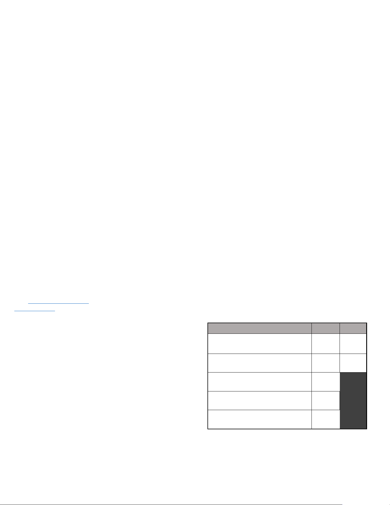
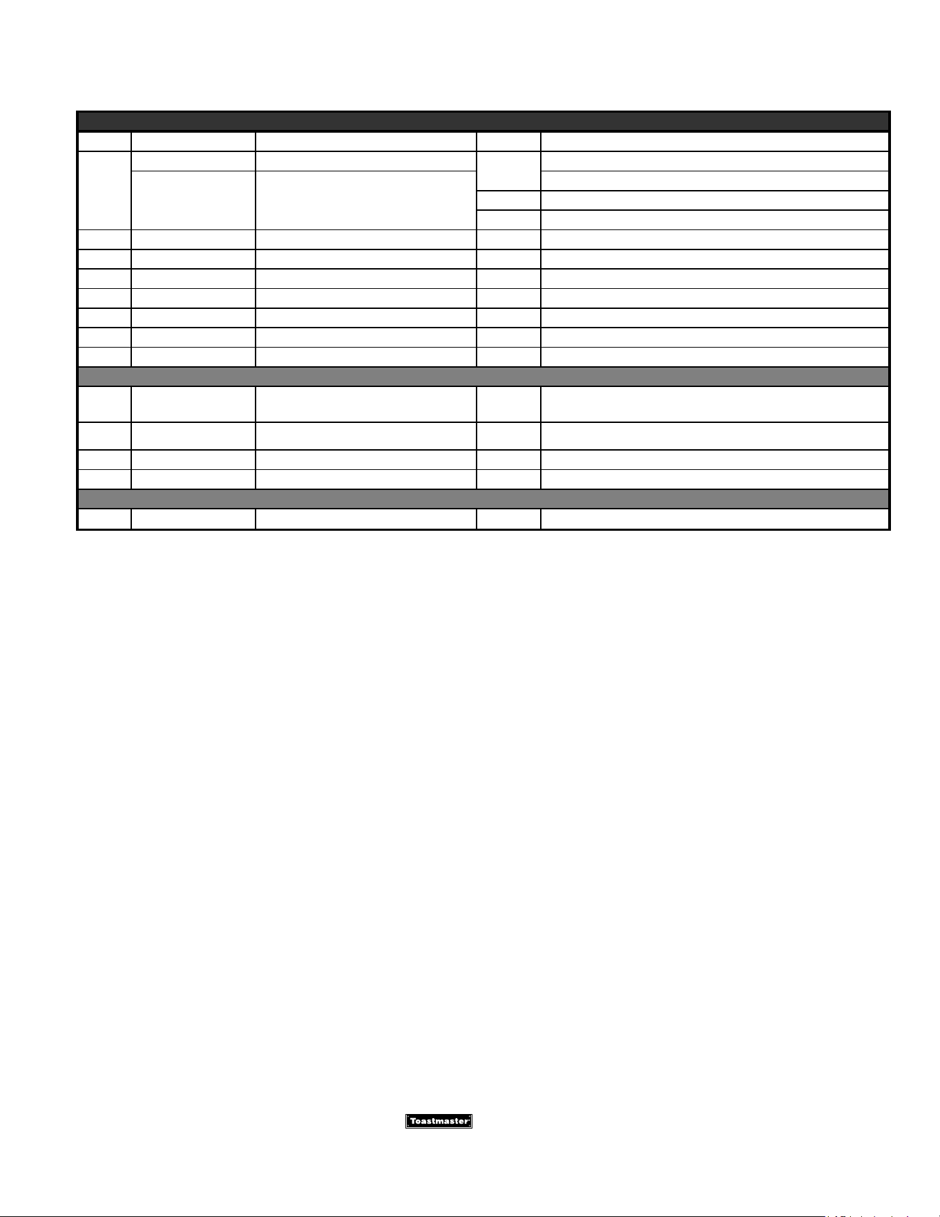
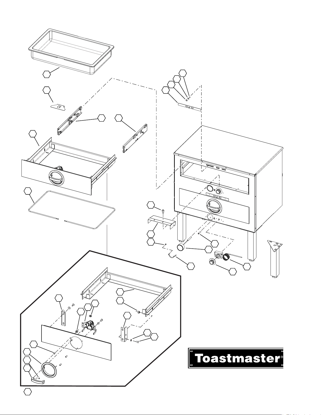
2M-3102301; Hot Food Server
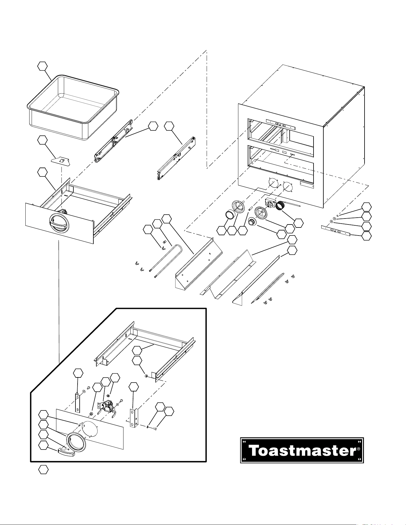
Hot Food Server
Single Drawer Models
Model: 3A20A, 3A80A, 3A81D
IL2097, Rev. - 10/11/2010
12
11
10
9
1
2
3
4
5
6
7
8
1413
15
16
17
18
31
30
28
29
24
20
19
23
21
22
27
26
25
32
(Items 23 thru 31)
Third Members
Sold as Assemlby Only
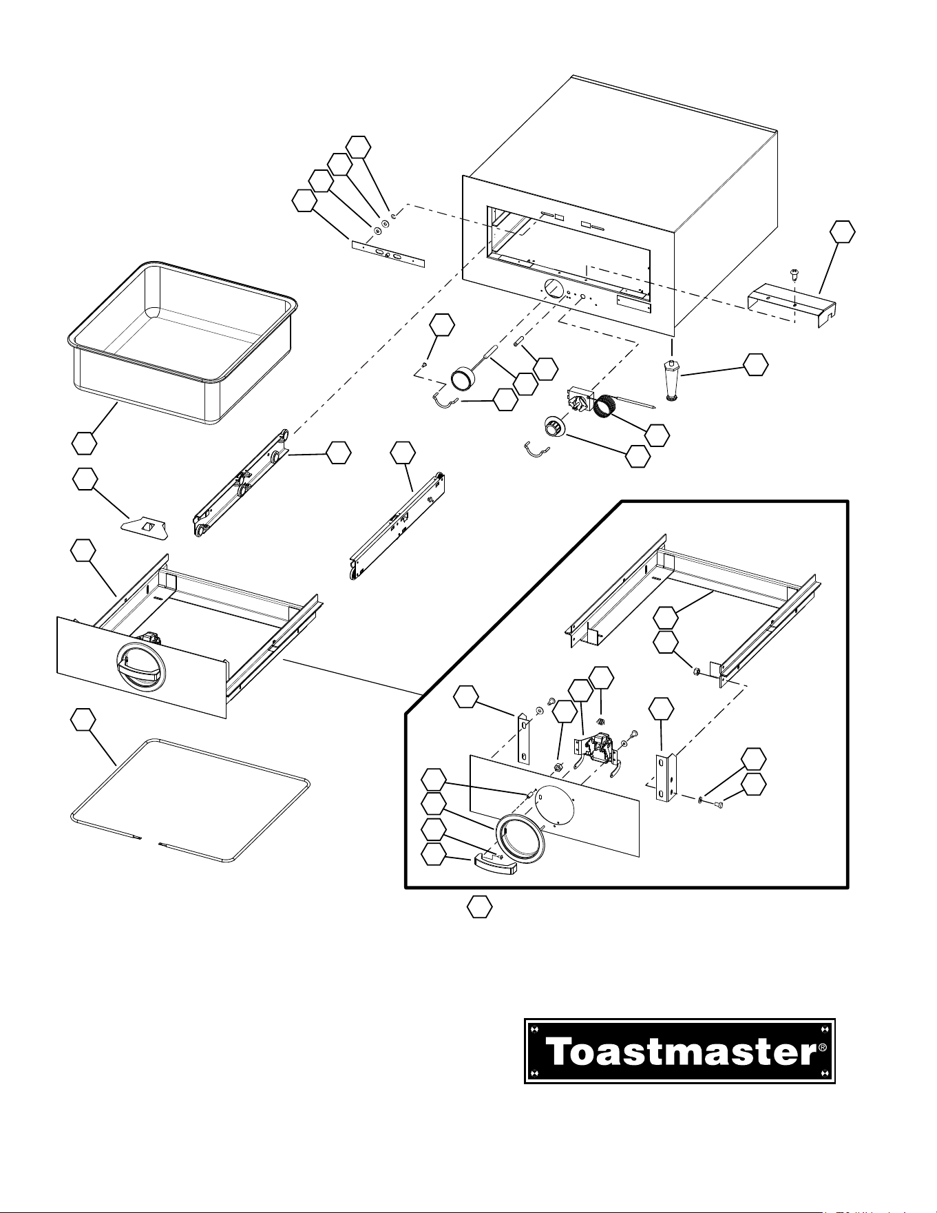
2M-3102301; Hot Food Server
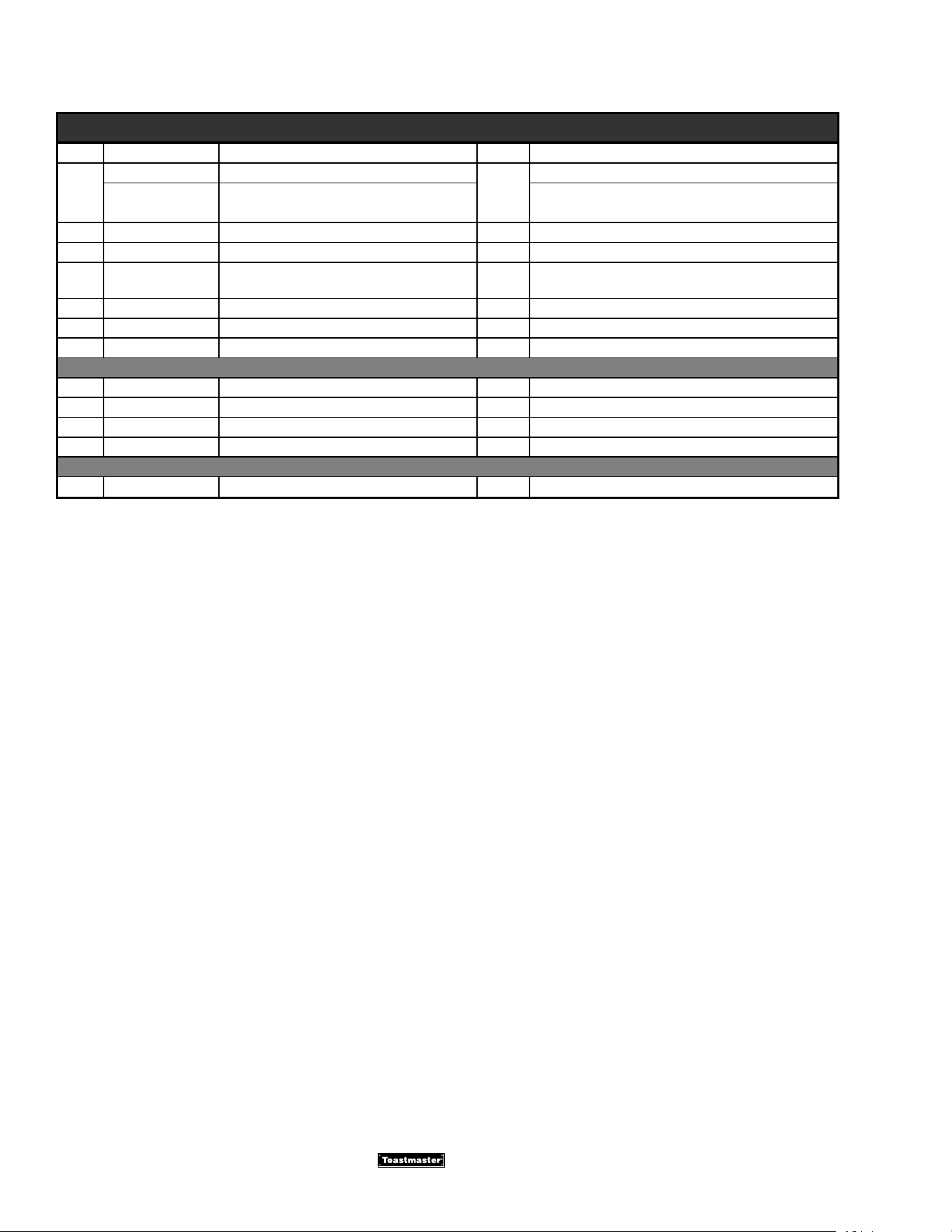
PARTS LIST
is a registered trademark of Toastmaster, A Middleby Company. All rights reserved.
ONE DRAWER HOT FOOD SERVER MODELS: 3A20A, 3A80A, 3A81D
Fig No Part No. Description Qty Application
1 C9-7005899 COVER,T’STAT 1
2 2R-1523B8301 LEG, 4INBLACK PLASTIC 4 3A81D-120KFC, 3A81DT09-120, 3A81DT72-240
3 2T-3B70A8929 THERMOSTAT,100-200F 1
4 2R-2100087 KNOB,TSTAT OFF & 0-10 1
5
C9-TC0069 LIGHT,SIGNAL ASSY RED-115
1
3A20AT09-120, 3A80AT09-120, 3A80AWC-120V,
3A81D-120KFC, 3A81DT09-120
C9-3B82D0181 ASSY,LIGHT SIGNAL RED 250 3A80AT72-240, 3A81DT72-240
6 2T-3004112 THERMOMETER 1
7 C9-3A80A3007 GUARD,KNOB CONTROL 2
8 2C-K1DS195 KNOB GUARD SCREW 4
9 2C-B102851 RING,RETAINING 4
9 2C-B102851 RING,RETAINING 6 3A81D-120KFC
10 2C-2001748 WASHER, SPRING #10 4
11 2C-3B82D8827 WASHER,FLAT 7/16 4
12 2R-7610283 ASSY,VENT SLIDE HFS 1
13
C9-3B22D0045 ASSY,CHANNEL THIRD MEMBER LF
1
3A20AT09-120
C9-3B82D0069 ASSY,CHANNEL THIRD MEMBER LF
3A80AT09-120, 3A80AT72-240, 3A80AWC-120V,
3A81DT09-120, 3A81DT72-240
14
C9-3B22D0041 ASSY,CHANNEL THIRD MEMBER RT
1
3A20AT09-120
C9-3B82D0067 ASSY,CHANNEL THIRD MEMBER RT
3A80AT09-120, 3A80AT72-240, 3A80AWC-120V,
3A81DT09-120, 3A81DT72-240
15
2D-3B22D8411 PAN 17-5/8 X 17-5/8 X 5-1
1
3A20AT09-120
2D-3B82D8411 PAN 23-3/4 X 14-38 X 5-1
3A80AT09-120, 3A80AT72-240, 3A80AWC-120V,
3A81D-120KFC, 3A81DT09-120, 3A81DT72-240
16 C9-7007086 COVER,CATCH HFS DRAWER 1
17
C9-3B22D0143 DRAWER CARRIAGE ASSY w/FRONT
1
3A20AT09-120
C9-3B82D0179 ASSY, DRAWER & CARRIAGE
3A80AT09-120, 3A80AT72-240, 3A80AWC-120V,
3A81D-120KFC
18
2N-3A20A8701 ELEMENT,HEATING 115V 450W
1
3A20AT09-120
2N-3A81D8701 ELEMENT,HEATING 115V 450W 3A80AT09-120, 3A80AWC-120V, 3A81DT09-120
2N-3A81D8703 ELEMENT, HEATING 220V 450W 3A80AT72-240, 3A81DT72-240
19
2W-3B22D0079 WLDMT, CARIAGE
1
3A20AT09-120
2W-3B82D0151 WLDMT, CARIAGE
3A80AT09-120, 3A80AT72-240, 3A80AWC-120V,
3A81D-120KFC, 3A81DT09-120, 3A81DT72-240
20 2C-32259 WELD NUT 1/4-20 SS 4
21 2C-A27469 WASHER,FLAT 1/4IN 7/8OD 1 4
22 2C-A6153 SCR,MS HH 1/4-20X1/2 18-8 4
23 C9-3B82D4065 DRAWER,FRT BRKT-LT 1
24 C9-3B82D4063 BRACKET,DRAWER FRONT RT 1
25 2C-2001347 NUT,KEPS 8-32 ZP 3
26 C9-3B82D0175 ASSY,CATCH BRACKET & TRUS 1
27 2P-3B82D8401 SPRING,DRAWER CATCH 1
28 2A-3B82D8311 SPACER,DRAWER FRONT,3/16X 3
29 C9-7608910 ASSY,DRAWER CUP HANDLE 1
31 2R-3101758 HANDLE,DRAWER 1
30
2C-35492
SCR,MS SLT FH 8-32X1/2 NP 2
(08/2018) Rev. D
2M-3102301; Hot Food Server
PARTS LIST
is a registered trademark of Toastmaster, A Middleby Company. All rights reserved.
ONE DRAWER HOT FOOD SERVER MODELS: 3A20A, 3A80A, 3A81D
Fig No Part No. Description Qty Application
32
C9-3B72D0147 ASSY,FRONT & CATCH DRAWER
1
3A20AT09-120
C9-3B82D0177 ASSY, DRAWER FRONT & CATCH
3A80AT09-120, 3A80AT72-240, 3A80AWC-120V,
3A81DT09-120, 3A81DT72-240
NI 2K-3002648 BUSHING, HEYCO STRAIGHT 1 3A81D-120KFC
NI 2K-B212E8717 BUSHING, STRAIN RELIEF 1 3A81DT09-120
NI C9-3A80A3009 COVER,BOTTOM 1
3A20AT09-120, 3A80AT09-120, 3A80AT72-240,
3A80AWC-120V
NI C9-7605845 ASSY, CORDSET (5-15P) 125V15 1 3A81D-120KFC, 3A81DT09-120
NI C9-7610652 ASSY, CORDSET(6-15P) 250V15 1 3A81DT72-240
NI C9-TC0049 CORD ASSY 120V 5-15P 8FT 1 3A80AWC-120V
WIRING DIAGRAMS
NI C9-3A20A8905 DIAGRAM,WIRING 115V 1 3A20AT09-120, 3A80AT09-120, 3A80AWC-120V
NI C9-3A20A8907 DIAGRAM, WIRING 230V 1 3A80AT72-240
NI C9-3A81D8901 DIAGRAM, WIRING 115V 1 3A81D-120KFC
NI C9-3A81D8905 DIAGRAM, WIRING 220V 1 3A81DT72-240
INSTALL INSTRUCTIONS
NI C9-3200085 INST,INSTALL 3A20 HFS AR 3A20AT09-120, 3A80AT09-120
(08/2018) Rev. D

2M-3102301; Hot Food Server
2M-3102301; Hot Food Server
Hot Food Server
Two, Three & Four Drawer,
Single Control Models
Model: 3B20A, 3B80A, 3C80A, 3D8XD
IL2098, Rev. A 5/6/2011
16
Third Members
Sold as Assemlby Only
19
15
14
13
11
12
7
6
5
8910
4
3
2
1
20
21
22
25
26
30
31
32
33
34 (items 25 thru 33)
27
28
29
23
24
18
17
2M-3102301; Hot Food Server
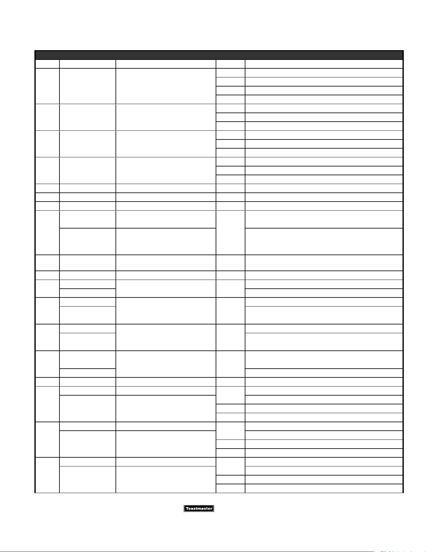
PARTS LIST
(08/2018) Rev. D
is a registered trademark of Toastmaster, A Middleby Company. All rights reserved.
SINGLE CONTROLS, HOT FOOD SERVER MODELS: 3B20AT, 3B80AT, 3B82DT, 3C80AT, 3D8XDT
Fig No. Part Number Description Quantity Application
1 2C-B102851 RING,RETAINING
8 3B20AT09-120, 3B20AT72-240
12 3B80AWC-120V, 3C80AT
16 3B80AT,3B82DT, 3D8XDT09-120
24 3D8XDT72-240
2 2C-3B82D8827 WASHER,FLAT 7/16
4 3B20AT, 3B80AT
6 3C80AT
8 3D8XDT
3 2C-2001748 WASHER, SPRING #10
4 3B20AT, 3B80AT, 3B82DT
6 3C80AT
8 3D8XDT
4 2R-7610283 ASSY,VENT SLIDE HFS
2 3B20AT, 3B80AT, 3B82DT
3 3C80AT
4 3D8XDT
5 2T-3B70A8929 THERMOSTAT,100-200F 1 ALL
6 C9-1523B0001 WLDMT,CONTROL CUP 1 ALL
7 2R-2100087 KNOB,TSTAT OFF & 0-10 1 ALL
8
C9-3B82D0181 ASSY, LIGHT SIGNAL 230V
1
3B20AT72-240, 3B80AT72-240, 3C80AT72-240,
3D8XDT72-240
C9-TC0069 LIGHT,SIGNAL ASSY RED-115
3B20AT09-120, 3B80AT09-120, 3B80AWC-120V,
3B82DT09-CFA, 3C80AT09-120, 3D8XDT09-120
9 C9-7609086
WLDMT,CUP THERMOMETER
MTG
1 ALL
10 2T-3004112 THERMOMETER 1 ALL
11
C9-7007051
GUARD,WIRE (FRT-BACK) 1
3B20AT09-120, 3B20AT72-240
C9-7007053 3B80AT, 3B80AWC, 3C80AT, 3D8XDT
12
C9-3B22D0029
ASSY,SHEATH ELEMENT RIGHT 1
3B20AT
C9-3B82D0047 3B80AT, 3B80AWC, 3B82DT, 3C80AT, 3D8XDT
13
C9-3B22D0031
ASSY,SHEATH ELEMENT LEFT 1
3B20AT
C9-3B82D0049 3B80AT, 3B80AWC, 3B82DT, 3C80AT, 3D8XDT
14
2N-3B82D8701
ELEMENT,HEATING 110V 500W 2
3B20AT, 3B80AT, 3B80AWC-120V, 3B82DT09-CFA
2N-3D8XD8701 3C80AT, 3D8XDT
15 2C-30397 CLIP ELEM M P 8 ALL
16
C9-3B22D0041 ASSY,CHANNEL THIRD MEMBER
2
3B20AT
C9-3B82D0067 ASSY,CHANNEL THIRD MEMBER
3B80AT, 3B80AWC, 3B82DT
3 3C80AT
4 3D8XDT
17
C9-3B22D0045 ASSY,CHANNEL THIRD MEMBER
2
3B20AT
C9-3B82D0069 ASSY,CHANNEL THIRD MEMBER
3B80AT, 3B80AWC, 3B82DT
3 3C80AT
4 3D8XDT
18
2D-3B22D8411 PAN 17-5/8 X 17-5/8 X 5-1
2
3B20AT
2D-3B82D8411 PAN 23-3/4 X 14-3/8 X 5-1
3B80AT, 3B80AWC, 3B82DT
3 3C80AT
4 3D8XDT
2M-3102301; Hot Food Server
PARTS LIST
(08/2018) Rev. D
is a registered trademark of Toastmaster, A Middleby Company. All rights reserved.
SINGLE CONTROLS, HOT FOOD SERVER MODELS: 3B20AT, 3B80AT, 3B82DT, 3C80AT, 3D8XDT
Fig No. Part Number Description Quantity Application
19 C9-7007086 COVER,CATCH HFS DRAWER
2 3B20AT, 3B80AT, 3B80AWC, 3B82DT
3 3C80AT
4 3D8XDT
20
C9-3B22D0143 DWR CARROAGE ASSY W/FRONT 2 3B20AT
C9-3B82D0179 ASSY, DRAWER CARRIAGE
2 3B80AT, 3B82DT
3 3C80AT
4 3D8XDT
21
2W-3B22D0079 WLDMT, CARIAGE
2
3B20AT09-120, 3B20AT72-240
2W-3B82D0151 WLDMT, CARIAGE
3B80AT09-120, 3B80AT72-240, 3B80AWC-120V, 3B82DT
3 3C80AT
4 3D8XDT
22 2C-32259 WELD NUT 1/4-20 SS
8 3B20AT, 3B80AT, 3B82DT
12 3C80AT
16 3D8XDT
23 2C-A6153 SCR,MS HH 1/4-20X1/2 18-8
8 3B20AT
16 3B80AT, 3B82DT
24 3C80AT
24 2C-A27469 WASHER,FLAT 1/4IN 7/8OD 1
8 3B20AT, 3C80AT
16 3B80AT, 3B80AWC, 3B82DT
32 3D8XDT
25 C9-3B82D4063 BRACKET,DRAWER FRONT RT
2 3B20AT, 3B80AT, 3B80AWC
4 3C80AT, 3B82DT
6 3D8XDT
26 C9-3B82D4065 DRAWER,FRT BRKT-LT
2 3B20AT, 3B80AT, 3B80AWC, 3B82DT
4 3C80AT
6 3D8XDT
27 2P-3B82D8401 SPRING,DRAWER CATCH
2 3B20AT, 3B80AT, 3B82DT
3 3C80AT
4 3D8XDT
28 C9-3B82D0175 ASSY,CATCH BRACKET & TRUS
2 3B20AT, 3B80AT, 3B80AWC, 3B82DT
3 3C80AT
29 2C-2001347 NUT,KEPS 8-32 ZP
6 3B20AT, 3B80AT, 3B82DT
9 3C80AT
12 3D8XDT
30 2A-3B82D8311 SPACER,DRAWER FRONT,3/16X
6 3B20AT, 3B80AT, 3B82DT
9 3C80AT
12 3D8XDT
31 C9-7608910 ASSY,DRAWER CUP HANDLE
2 3B20AT, 3B80AT, 3B80AWC, 3B82DT
3 3C80AT
4 3D8XDT
32 2C-3023A8811 SCR,MS SLT FH 8-32X1/2 NP
4 3B20AT, 3B80AT, 3B82DT
6 3C80AT
8 3D8XDT
33 2R-3101758 HANDLE,DRAWER
2 3B20AT, 3B80AT, 3B82DT
3 3C80AT
4 3D8XDT
2M-3102301; Hot Food Server
PARTS LIST
(08/2018) Rev. D
is a registered trademark of Toastmaster, A Middleby Company. All rights reserved.
SINGLE CONTROLS, HOT FOOD SERVER MODELS: 3B20AT, 3B80AT, 3B82DT, 3C80AT, 3D8XDT
Fig No. Part Number Description Quantity Application
34
C9-3B72D0147 ASSY,FRONT & CATCH DRAWER
2
3B20AT
C9-3B82D0177 ASSY,DRAWER FRONT CATCH
3B80AT, 3B82DT
3 3C80AT
4 3D8XDT
NI 2K-31040 BUSHING HEYCO 7/8 OD 1 3B80AWC-120V, 3B82DT09-CFA
NI 2K-B212E8717 BUSHING, STRAIN RELIEF 1 3D8XDT
NI C9-1511E0029 ASSY, CORDSET(5-15P)125V15 1 3D8XDT09-120
NI C9-1511E0031 ASSY, CORDSET-250V15A 3’ 6I 1 3D8XDT72-240
NI C9-TC0048 CORD SET ASSY 16-3 HSJO 1 3B80AWC-120V, 3B82DT09-CFA
NI 2P-Z20782 4-5/8” SWIVEL CASTER w/BRAKE 2 3B82DT09-CFA
NI 2P-Z20783 4-5/8” SWIVEL CASTER 2 3B82DT09-CFA
WIRING DIAGRAMS
AR C9-3B20A8905 DIAGRAM,WIRING 115V 1
3B20AT09-120, 3B80AT09-120, 3B80AWC-120V,
3C80AT09-120, 3B82DT09-CFA
AR C9-3B20A8911 DIAGRAM, WIRING 220V 1 3B20AT72-240, 3B80AT72-240, 3C80AT72-240
AR C9-3B22D8911 DIAGRAM, WIRING 220V 1 3D8XDT72-240
AR C9-3B72D8913 DIAGRAM, WIRING 115V 1 3D8XDT09-120
INSTALL INSTRUCTIONS
AR C9-3200084 INST,INSTALL 3B20 HFS AR 3B20AT09-120, 3B20AT72-240
2M-3102301; Hot Food Server
Hot Food Server
Two, Three & Four Drawer,
Individual Drawer Control Models
Model: 3B84A, 3B84D, 3C84A, 3C84D
IL2099, Rev. - 10/11/2010
1
2
3
4
5
6
7
8
9
10
11
12
13
15
16
17
18
20
21
23
25
24
28
29
30
31
26
27
22
19
14
32 (items 21 thru 31)
Third Members
Sold as Assemlby Only
Includes;
Items 19 thru 31
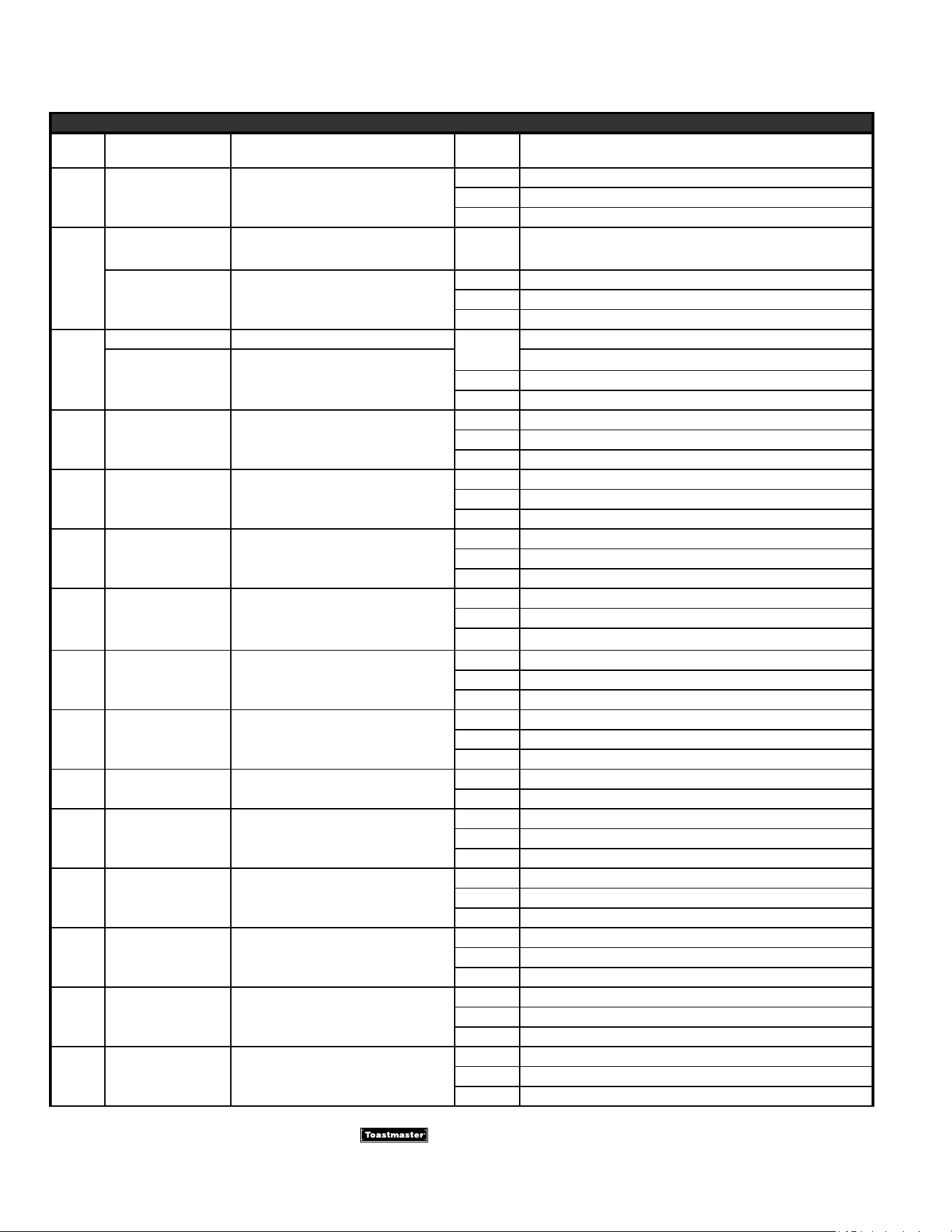
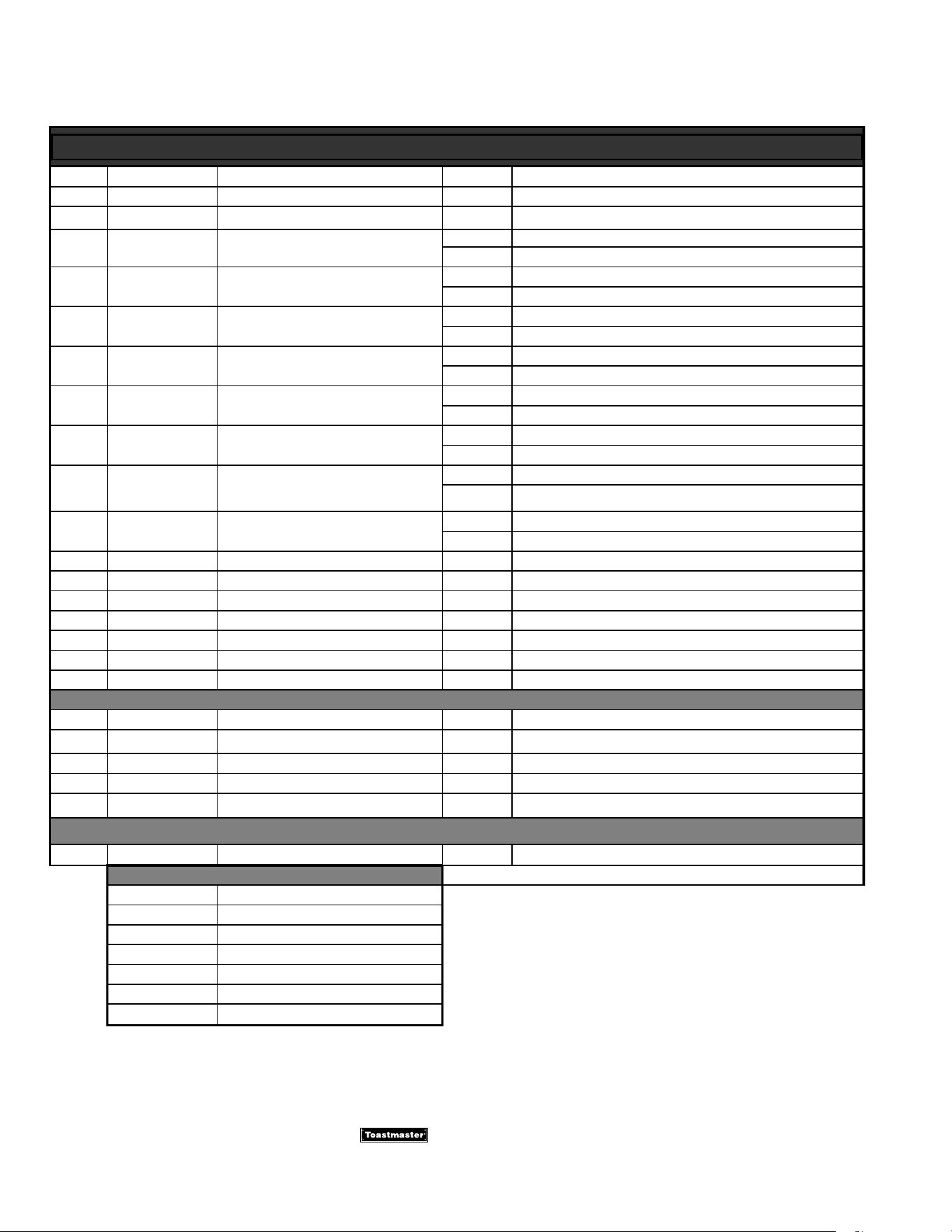
PARTS LIST
08/2018 REV D
SEPARATE DRAWER CONTROLS, HOT FOOD SERVER MODELS: 3B84A, 3B84D, 3C84A, 3D84D
Fig No. Part No Description Quantity Application
2 3B84A, 3B84D
1 2R-7610283 ASSY,VENT SLIDE HFS
3 3C84A, 3C84D
2 2C-2001863 WASHER,FLAT .203X.63OX.05
3B84A, 3B84D
3C84A, 3C84D
3 2C-2001748 WASHER,SPRING #10
4 3B84A, 3B84D
6 3C84A, 3C84D
4 2C-B102851 RING,RETAINING 12 3B84AT09-120
5 2T-3B70A8929 THERMOSTAT,100-200F
3B84A, 3B84D
3C84A, 3C84D
6 2R-2100087 KNOB,TSTAT OFF & 0-10
3B84A, 3B84D
3C84A, 3C84D
C9-TC0069 LIGHT,SIGNAL ASSY RED-115
3B84AT09-120, 3B84DT09-120, 3B84DT09-KFC
7
3C84AT09-120, 3C84DT09-120, 3C84DT09-120
C9-E336A0116
ASSY,LIGHT SIGNAL RED 250
2 3B84AT72-240 / -SA , 3B84DT72-240
3 3C84DT72-240, 3C84AT72-240
8 2T-3004112 THERMOMETER
2 3B84A, 3B84D
3 3C84A, 3C84D
9 2R-2600068 BLANK,GUARD KNOB CONTROL
4 3B84A, 3B84D
6 3C84A, 3C84D
10 2C-K1DS195 KNOB GUARD SCREW
8 3B84A, 3B84D
12 3C84A, 3C84D
11 C9-7005899 COVER,T’STAT
2
3
3B84A, 3B84D
3C84A, 3C84D
12 2C-35487 SCREW 8-32X5/16 PH TR HD
4 3B84A, 3B84D
6 3C84A, 3C84D
13 C9-3B82D0067 ASSY,CHANNEL THIRD MEMBER
2 3B84A, 3B84D
3 3C84A, 3C84D
14 C9-3B82D0069 ASSY,CHANNEL THIRD MEMBER
2 3B84A, 3B84D
3 3C84A, 3C84D
15 2D-3B82D8411 PAN 23-3/4 X 14-3/8 X 5-1
2 3B84A, 3B84D
3 3C84A, 3C84D
16 C9-7007086 COVER,CATCH HFS DRAWER
2 3B84A, 3B84D
3 3C84A, 3C84D
17 C9-3B82D0179 ASSY,DRAWER CARRIAGE
3B84A, 3B84D
3C84A, 3C84D
2N-3A81D8701 ELEMENT,HEATING 115V 450W
2 3B84AT09-120, 3B84DT09-120, 3B84DT09-KFC
18
3 3C84AT09-120, 3C84AT09-120, 3B84DT09-120
2N-3A81D8703 ELEMENT,HEATING 220V 450W
2 3B84AT72-240 / -SA, 3B84DT72-240
3 3C84AT72-240, 3C84DT72-240
19 2W-3B82D0151 WLDMT,CARRIAGE
2 3B84A, 3B84D
3 3C84A, 3C84D
20 2C-32259 WELD NUT 1/4-20 SS
8 3B84A, 3B84D
12 3C84A, 3C84D
21 2C-A6153 SCR,MS HH 1/4-20X1/2 18-8
16 3B84A, 3B84D
24 3C84A, 3C84D
22 2C-A27469 WASHER,FLAT 1/4IN 7/8OD 1
16 3B84A, 3B84D
24 3C84A, 3C84D
is a registered trademark of Toastmaster, A Middleby Company. All rights reserved.
4
6
2
3
2
3
2
3
2
3
2M-3102301; Hot Food Server
2M-3102301; Hot Food Server
PARTS LIST
(08/2018) Rev. D
is a registered trademark of Toastmaster, A Middleby Company. All rights reserved.
Separate Drawer Controls, Hot Food Server Models: 3B84A, 3B84D, 3C84A, 3D84D
Fig No. Part No Description Quantity Application
23 C9-3B82D4065 DRAWER,FRT BRKT-LT 2 3B84AT09-120
24 C9-3B82D4063 BRACKET,DRAWER FRONT RT 2 3B84AT09-120
25 2P-3B82D8401 SPRING,DRAWER CATCH
2 3B84A, 3B84D
3 3C84A, 3C84D
26 C9-3B82D0175 ASSY,CATCH BRACKET & TRUS
2 3B84A, 3B84D
3 3C84A, 3C84D
27 2C-2001347 NUT,KEPS 8-32 ZP
6 3B84A, 3B84D
9 3C84A, 3C84D
28 2A-3B82D8311 SPACER,DRAWER FRONT,3/16X
6 3B84A, 3B84D
9 3C84A, 3C84D
29 C9-7608910 ASSY,DRAWER CUP HANDLE
2 3B84A, 3B84D
3 3C84A, 3C84D
30
2C-35492
SCR,MS SLT FH 8-32X1/2 NP
4 3B84A, 3B84D
6 3C84A, 3C84D
31 2R-3101758 HANDLE,DRAWER
2 3B84A, 3B84D
3 3C84A, 3C84D
32 C9-3B82D0177 ASSY,DRAWER FRONT & CATCH
2 3B84A, 3B84D
3 3C84A, 3C84D
NI 2A-Z0314 FOOT, 4” DIE CAST 4 3B84DT09-120, 3B84DT72-240
NI 2B-55036 RACK,DIVIDER 15 SECTION 2 3B84DT09-KFC
NI 2K-45609 BUSHING HEYCO 3/8 ID .500 1 3B84DT09-120
NI 2K-B212E8717 BUSHING,STRAIN RELIEF 1 3B84AT09-120
NI C9-45005 KIT, KFC SWVL CASTER W/BRK 1 3B84DT09-KFC
NI C9-7605845 ASSY,CORDSET(5-15P)125V15 1 3B84DT09-120
NI C9-7610652 ASSY,CORDSET(6-15P)250V15 1 3B84DT72-240, 3C84DT72-240
WIRING DIAGRAMS
AR C9-8000358 DIAGRAM, WIRING 120 3C84A 1 3C84AT09-120
AR C9-8000358-1 DIAGRAM, WIRING 208/240V 1 3C84AT72-240
AR C9-8000358-2 DIAGRAM, WIRING 120V 3C84D 1 3C84DT09-120
AR C9-8000358-3 DIAGRAM, WIRING 208/240V 1 3C84DT72-240
AR C9-8000361 DIAGRAM, WIRING 120V 1 3B84AT09-120
INSTALL INSTRUCTIONS
NI
C9-3102206 INST,INSTALL,3B84 & 3C84
AR 3B84AT, 3C84AT
ACCESSORIES
7C-3L6 LEG SET 6” ADJ FOOT HFS
7C-3L9 LEG SET 9” ADJ FOOT HFS
7C-3L12 LEG SET 12” ADJ FOOT HFS
7C-3L15 LEG SET 15” SDJ FOOT HFS
7C-3M3 CASTER KIT 3” SWIVEL
7C-3M4 CASTER SET (2 SWVL, 2 RDG)
7C-3M338STSB CASTER SET (4) 2 w/BRK


STAR INTERNATIONAL HOLDINGS INC. COMPANY
Star - Holman - Lang - Wells - Bloomeld - Toastmaster
265 Hobson Street, Smithville, TN 37166 U.S.A.
(800) 264-7827
www.star-mfg.com