El nuevo grado de confort.
MR
Commercial
92-109946-01
INSTALLATION AND OPERATION MANUAL
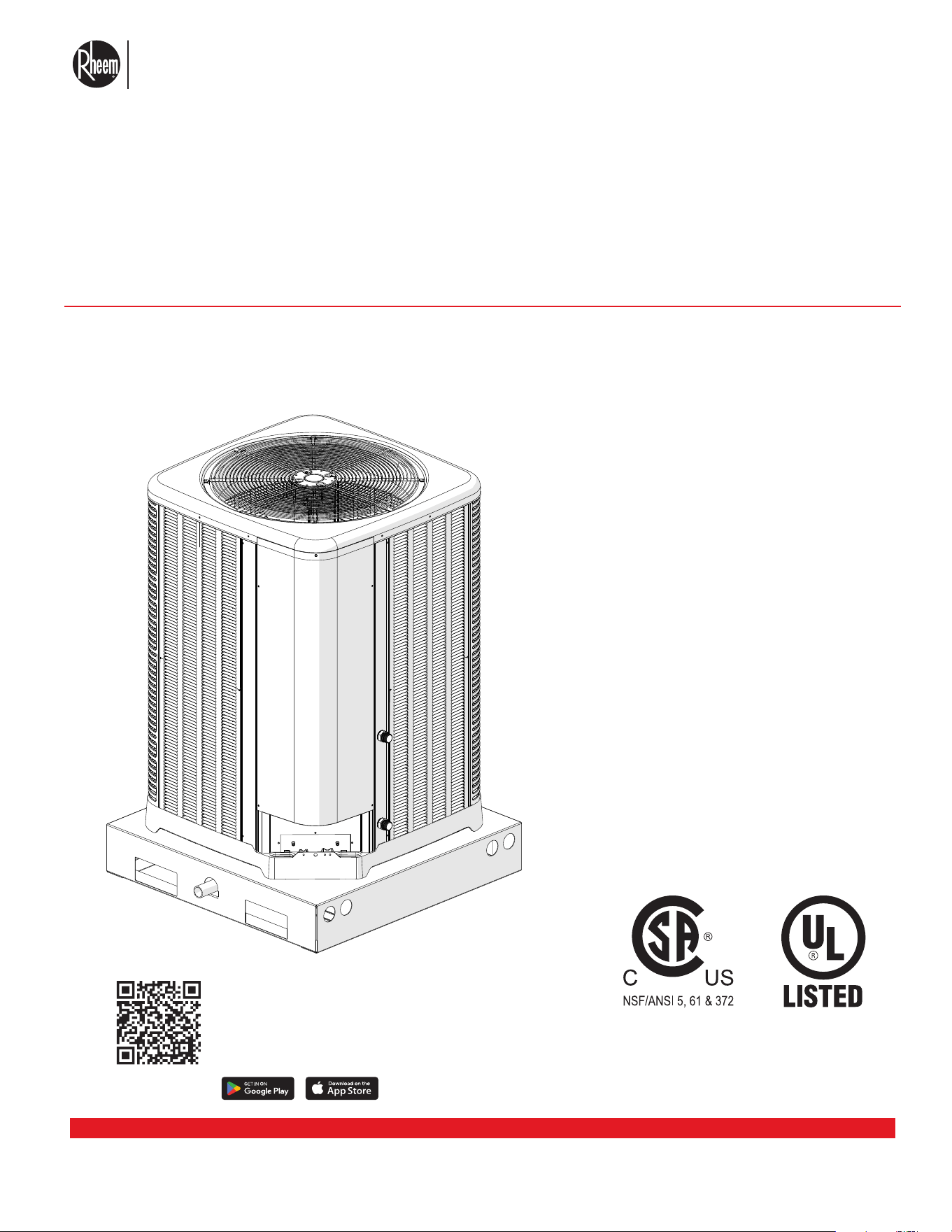
HEAT PUMP WATER HEATER
MONOBLOCK
Model Series
RMHPHDA068
RMHPHDA120
FOR YOUR SAFETY: Do not store or
use gasoline or other flammable vapors
and liquids or other combustible materi-
als in the vicinity of this or any other ap-
pliance. This may result in an explosion
or fire.
NOTE: The instructions in this man-
ual are for the use of qualified in-
dividuals specially trained and ex-
perienced in the installation and
maintenance of this type of equip-
ment and related system compo-
nents. Installation and service per-
sonnel are required to be licensed
by some states. Persons not quali-
fied shall not attempt to install, ser-
vice, or maintain this equipment.
This manual should be maintained in
legible condition and kept adjacent to
the heat pump heater or in a safe place
for future use.
USE THE CONTRACTOR APP FOR ENHANCED
INSTALLATION AND SERVICE SUPPORT.
SCAN QR Code to download the contractor
app onto your smart device

El nuevo grado de confort.
MR
Commercial HEAT PUMP WATER HEATER MONOBLOCK - I&O MANUAL
TOC Page 1
CONTENTS
1.0 SAFETY INFORMATION ..............................................................................................................1
2.0 GENERAL INFORMATION ...........................................................................................................2
2.1 INITIAL REVIEW OF PRODUCT RECEIVED ...................................................................................................2
2.2 SAFETY STATEMENTS ................................................................................................................................... 3
2.3 MODEL NUMBER AND NOMENCLATURE ......................................................................................................4
2.4 DIMENSIONS. ................................................................................................................................................... 5
3.0 INSTALLATION ............................................................................................................................. 6
3.1 IMPORTANCE OF QUALITY INSTALLATION ...................................................................................................6
3.1.1 WATER SUPPLY QUALITY. ...........................................................................................................................8
3.1.2 HEAT PUMP WATER HEATER OVERVIEW .................................................................................................. 9
3.2 MATERIALS AND TOOLS NEEDED FOR INSTALLING UNIT. .........................................................................10
3.3 CLEARANCES FOR INSTALLATION ................................................................................................................11
3.4 ELECTRICAL WIRING DIAGRAM AND FIELD CONNECTIONS ....................................................................14
3.5 SKY-35 CONTROLLER FOR MULTIPLE HYDRONIC HEAT SOURCES ......................................................... 20
3.6 ANCHOR INSTRUCTIONS FOR HIGH WIND LOCATION ............................................................................... 26
3.6.1 ANCHOR INSTRUCTIONS FOR SEISMIC LOCATION .................................................................................30
3.7 WATER PIPING CONNECTIONS ....................................................................................................................33
3.7.1 PIPING DIAGRAM FOR SINGLE PASS WATER HEATING ..........................................................................34
3.7.2 PIPING DIAGRAM FOR MULTIPASS WATER HEATING. ............................................................................. 37
3.7.3 PIPING DIAGRAM FOR SPACE HEATING. ..................................................................................................39
3.8 INDOOR INSTALLATION LOCATION CONSIDERATIONS. ............................................................................. 40
4.0 START-UP ...................................................................................................................................42
4.1 HEAT PUMP WATER HEATER PRE-START CHECK LIST. .............................................................................42
4.2 SYSTEM START UP AND OPERATIONAL CHECKUP. ....................................................................................43

El nuevo grado de confort.
MR
Commercial HEAT PUMP WATER HEATER MONOBLOCK - I&O MANUAL
TOC Page 2
CONTENTS
5.0 SERVICE AND MAINTENANCE .............................................................................................45
5.1 MAINTENANCE .............................................................................................................................................................45
5.1.1 WORKING PERSONNEL ............................................................................................................................... 46
5.2 REFRIGERANT CONNECTIONS SERVICE AND CHECK. ..............................................................................46
6.0 DIAGNOSTICS ..........................................................................................................................48
6.1 WHAT TO DO IN CASE OF FAILURES ...........................................................................................................48
6.2 ERROR CODES. ............................................................................................................................................... 53
7.0 REPLACEMENT PARTS ..........................................................................................................57
7.1 BEFORE BEGINNING DECOMMISSIONING ...................................................................................................61
7.2 DECOMMISSIONING PROCEDURE. ...............................................................................................................61
8. CERTIFICATE OF LIMITED WARRANTY ................................................................................62
IF YOU NEED SERVICE ................................................................................................................. 65
El nuevo grado de confort.
MR
Commercial HEAT PUMP WATER HEATER MONOBLOCK - I&O MANUAL
Page 1
1.0 SAFETY INFORMATION
WARNINGS:
• These instructions are intended as an aid to qualified,
licensed service personnel for proper installation, ad-
justment, and operation of this unit. Read these in-
structions thoroughly before attempting installation
or operation. Failure to follow these instructions may
result in improper installation, adjustment, service,
or maintenance, possibly resulting in fire, electrical
shock, property damage, personal injury, or death.
• The unit must be permanently grounded. Failure to
do so can cause electrical shock resulting in severe
personal injury or death.
• Turn off electric power at the fuse box or service pan-
el before making any electrical connections.
• Complete the ground connection before making line
voltage connections. Failure to do so can result in
electrical shock, severe personal injury, or death.
• Disconnect all power to unit before starting mainte-
nance. Failure to do so can cause electrical shock
resulting in severe personal injury or death.
• Never assume the unit is properly wired and/or
grounded. Always test the unit cabinet with a non-
contact voltage detector available at most electri-
cal supply stores or home centers before removing
access panels or coming into contact with the unit
cabinet.
• Do not use oxygen to purge lines or pressurize sys-
tem for leak test. Oxygen reacts violently with oil,
which can cause an explosion resulting in severe per-
sonal injury or death. Nitrogen is recommended for
purge or leak check.
• The top of the scroll compressor shell is hot. Touch-
ing the compressor top may result in serious personal
injury.
• The manufacturer’s warranty does not cover any dam-
age or defect to the unit caused by the attachment
or use of any components, accessories, or devices
(other than those authorized by the manufacturer)
into, onto, or in conjunction with the heat pump. You
should be aware that the use of unauthorized compo-
nents, accessories, or devices may adversely affect
the operation of the heat pump and may also endan-
ger life and property. The manufacturer disclaims any
responsibility for such loss or injury resulting from the
use of such unauthorized components, accessories,
or devices.
CAUTION:
The compressor has an internal overload protector. Un-
der some conditions, it can take up to 2 hours for this
overload to reset. Make sure overload has had time to
reset before condemning the compressor.
REFRIGERANT WARNINGS:
WARNING: Risk of fire or explosion. Dispose of re-
frigerant properly in accordance with federal or local
regulations. Flammable refrigerant used.
WARNING: Risk of fire or explosion due to flamma-
ble refrigerant used. Follow handling instructions care-
fully in compliance with national and local regulations.
WARNING: Do not use means to accelerate the de-
frosting process or to clean, other than those recom-
mended by the manufacturer.
WARNING: The appliance shall be stored in a room
without continuously operating ignition source (for ex-
ample: open flames, an operating gas appliance or an
operating electric heater.)
WARNING: Do not pierce or burn.
WARNING: Be aware that refrigerants may not con-
tain an odor.
WARNING: Appliance shall be installed, operated
and stored in a room with a floor area larger than 33.5
to 57.9 m
2
. See section 3.8 for more information about
indoor installations.
WARNING: Risk of electric shock. Can cause injury
or death. Disconnect all remote electric power supplies
before servicing.
!
!
!
!
!
!
!
!
!
!
El nuevo grado de confort.
MR
Commercial HEAT PUMP WATER HEATER MONOBLOCK - I&O MANUAL
Page 2
2.0 GENERAL INFORMATION
2.1 INITIAL REVIEW OF PRODUCT RECEIVED
Using the image on the right of this page please
locate and record your model and serial number. Once
you have done this, please make sure you also have the
following information on hand:
• Name, phone number, and email address of home-
owner
• Physical address of where the unit is installed;
please include any ‘subdivision’ or similar informa-
tion
• Any service challenges present at the house/
neighborhood: gated community, locked access at
house, guard dog, etc.
• Date of installation of the new unit
• Name and phone number of the professional and
licensed entity that performed the installation for
you
This would also be a good time to review both the man-
ual and the warranty so that you are aware of how to
correctly operate your new equipment as well as how
to keep from voiding any aspects of your warranty. Dur-
ing the life of your unit, please feel free to contact us
with any questions you may have about operation, war-
ranty, and/or service.
Thank you for choosing us to satisfy your water heater
needs!
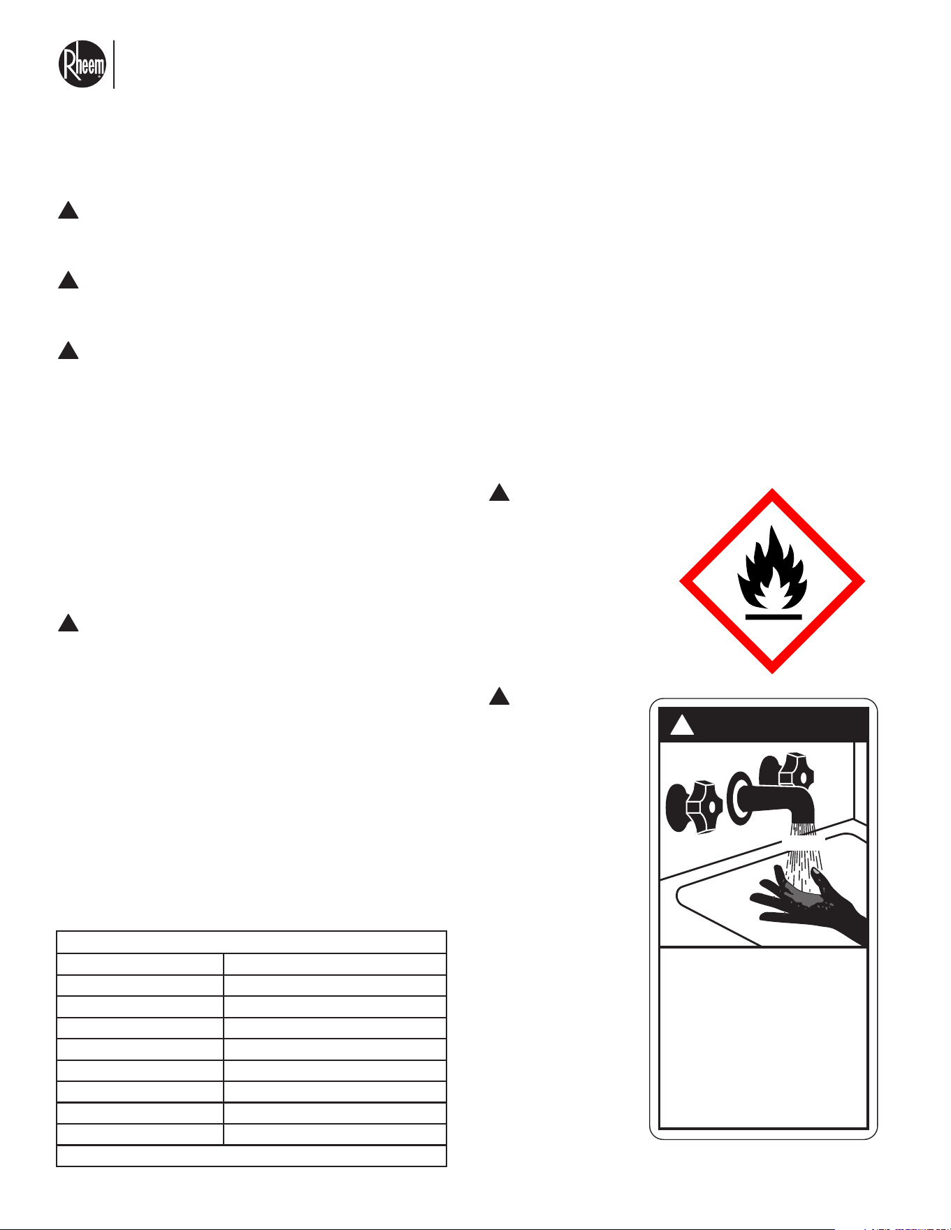
Product Serial number and installation/
startup date:
COMMERCIAL HEAT PUMP
WATER HEATER
CONFORMS TO ANSI-UL 60335-2-40
CERTIFIED TO ASHRAE 118.1
APPROVED FOR INDOOR AND OUTDOOR USE
Model Number:
Serial Number:
Voltage:
Compressor, Amp:
Fan Motor, Amp:
Min. Circuit Ampacity, Amp:
Maximum Overcurrent Protective Device:
Factory Charge R-454B:
Maximum Allowable Pressure PSI (MPa):
Water flow (Max - Min)
Manu. Date:
Max supply water temperature: °F (°C)
Max supply water pressure: PSIG (Mpa)
F.L.A
lbs. / oz
HIGH / LOW
GMP / LPM
H. P.
Short-circuit current: 5 kA rms symmetrical, 460 V maximum
ASSEMBLED IN MEXICO
RMHPHDA068
W122519343
460V-3-60Hz
25
2.3 1/2
33.5
50
550 (3.8)
5-20 / 19-75.7
03/2025
135
65 (0.45)
250 (1.72)
4 4
El nuevo grado de confort.
MR
Commercial HEAT PUMP WATER HEATER MONOBLOCK - I&O MANUAL
Page 3
2.2 SAFETY STATEMENTS
WARNINGS — PAY ATTENTION TO THESE TERMS
DANGER:
Indicates the presence of immediate hazards which will cause severe personal injury, death, or substantial property
damage if ignored.
WARNING:
Indicates the presence of hazards or unsafe practices which could cause severe personal injury, death, or substantial
property damage if ignored.
CAUTION:
Indicates the presence of hazards or unsafe practices which could cause minor personal injury or product or prop-
erty damage if ignored.
NOTICE:
Indicates special instructions on installation, operation, or maintenance which are important but not related to per-
sonal injury hazards.
!
!
!
This manual, as well as the heat pump water heater it-
self, contains UL-approved product safety signs and
labels. Please read these signs and labels as they
convey important safety information about hazards
that may be potentially present in and around the heat
pump water heater.
CAUTION: Elevated water temperature can
be hazardous. The U.S. Consumer Product
Safety Commission has these guidelines:
1. Stored water temperatures should not exceed
180°F ( 82°C). High water temperatures can cause
serious burns and scalding. Always install a mixing
valve to prevent hot water from entering building
directly.
2. This is an appliance that should not be accessible
to the general public. Special precautions should
be taken, so that only specialized personnel have
access to this appliance. Children should not be al-
lowed to play near or with appliance; elderly and
any non-qualified personnel should not be near ap-
pliance.
WARNING: The
heat pump water
heaters are charged
with R-454B refriger-
ant. Ensure that all
service work is done
with gauges and
equipment suitable
for R-454B.
!
!
WARNING: This
unit contains R-
454B refrigerant.
Follow all safety
precautions when
accessing the
refrigerant sys-
tem. Service by
qualified person-
nel only.
!
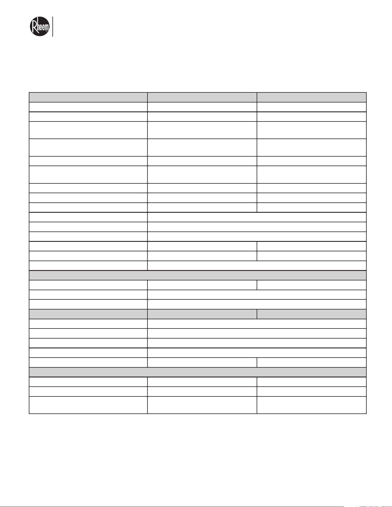
DANGER
!
HOT
Water temperature over 125° F (52°C)
can cause severe burns instantly or
death from scalds.
Children, disabled and elderly are
at highest risk of being scalded.
See instruction manual before
setting temperature at water
heater.
Feel water before bathing or
showering.
Temperature limiting valves are
available, see manual.
BURN
TIME / TEMPERATURE RELATIONSHIP IN SCALDS
Water Temperature Time to Produce a Serious Burn
120°F (49°C) More than 5 minutes
125°F (52°C) 1½ to 2 minutes
130°F (54°C) About 30 seconds
135°F (57°C) About 10 seconds
140°F (60°C) Less than 5 seconds
145°F (63°C) Less than 3 seconds
150°F (66°C) About 1½ seconds
155°F (68°C) About 1 second
Table courtesy of Shriners Burn Institute
El nuevo grado de confort.
MR
Commercial HEAT PUMP WATER HEATER MONOBLOCK - I&O MANUAL
Page 4
2.3 MODEL NUMBER AND NOMENCLATURE
MODEL RMHPHD 068 120
Heating Capacity* Btu [kW] single pass 68000 [20] 120000 [35]
COP* single pass 4.5 4.5
Heating capacity at 5°F ambient** Btu
[kW] single pass
68000 [20] 120000 [35]
Heating Capacity* Btu [kW] Multipass
(75°F ambient, 70°F inlet water)
78,000 [23] 118000 [34]
COP, Multipass 4.0 3.0
Heating capacity at 5°F ambient** Btu
[kW] Multipass
60000 [17.5] 90000 [26]
COP at 5°F ambient 1> 1>
COP at -13°F 1> 1>
Outdoor sound rating dB*** 75 75
Condenser Braze plate exchanger
Heat exchanger type Refrigerant to water
Tube diameter water side 1" NPT
Number of plates 52 96
Flow rate 5-15 GPM 5-20 GPM
Water Pressure PSI [MPa] : 65 PSI [0.45]
Evaporator - Fin type
Evaporator height 32" 48"
Rows / FPI 1/22
Refrigerant metering device Electronic expansion valve
Outdoor Fan - Type Axial Axial
No. Blades / Diameter in. [mm] 3 blades / 26"
CFM 6000
No. Motors/HP 1 / ½ HP
Motor RPM 1100
Refrigerant Charge Oz. [g] 70 [1984.47] 92 [2608.15]
Weights
Net Weight lbs. [kg] 346.13 [157] 462.97 [210]
Ship Weight lbs. [kg] 359.35 [163] 482.81 [219]
Minimum area for install indoor
sqft [m2]
360.7 [33.5] 623.2 [57.9]
*Calculated per ASHRAE DOE 118.1-2012. Water inlet 70°F, ambient 80°F Dry Bulb and 50°F delta increase. Unit
operating in single pass mode.
** Calculated at Water inlet 70°F and 50°F delta increase.
*** Measured at 3ft [1m] from unit.
Elevation does not affect the minimum area for install on indoor applications.
PHYSICAL DATA
El nuevo grado de confort.
MR
Commercial HEAT PUMP WATER HEATER MONOBLOCK - I&O MANUAL
Page 5
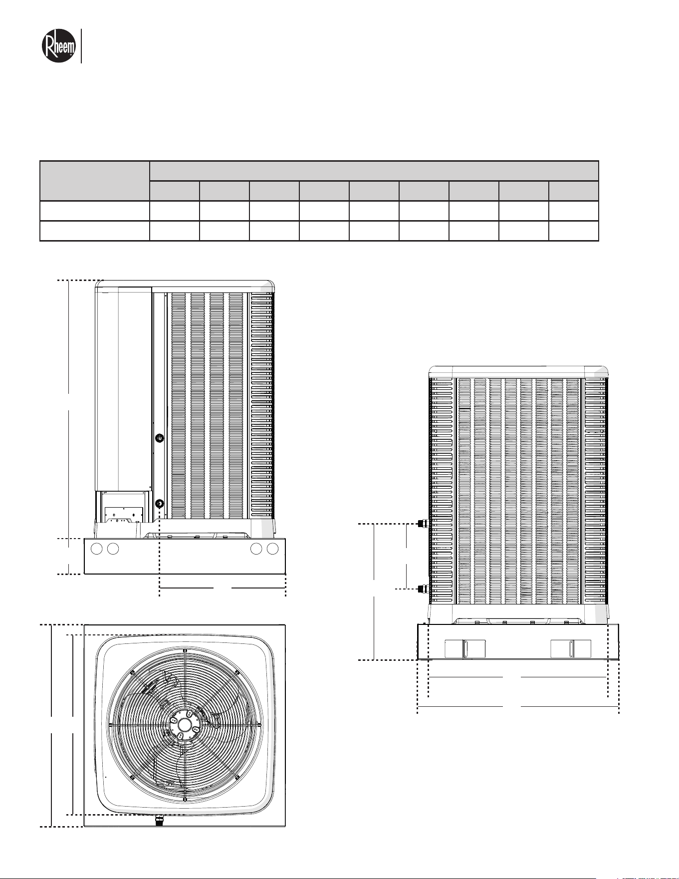
2.4 DIMENSIONS
MODEL NUMBER
DIMENSIONS
A B C D E F G H I
RMHPHDA068V000 7" 35" 36" 40" 36" 40" 13" 27" 25"
RMHPHDA120V000 7" 51" 36" 40" 36" 40" 13" 27" 25"
UNIT DIMENSIONS
A
B
C
G
HI
D
EF
All dimensions shown above are in inches.
El nuevo grado de confort.
MR
Commercial HEAT PUMP WATER HEATER MONOBLOCK - I&O MANUAL
Page 6
3.1 IMPORTANCE OF QUALITY INSTALLATION
3.0 INSTALLATION
WARNING:
Improper installation, or not made in accor-
dance with these instructions, can result in un-
satisfactory operation and/or dangerous condi-
tions and will void warranty.
INTRODUCTION
The information contained in this manual has been pre-
pared to assist in the proper installation, operation, and
maintenance of the air conditioning system by a quali-
fied installer.
The images contained within this document may
not be an exact representation of every unit, acces-
sory, installation, etc. All dimensions contained in this
document are approximations. We reserve the right to
change the content of this document at any time.
IMPORTANCE OF QUALITY
INSTALLATION
The equipment must be stored in a way that prevents
mechanical damage from occurring.
A quality installation is critical to assure safety, reliabili-
ty, comfort, and customer satisfaction. Strict adherence
to applicable codes, the information in this installation
manual, and the thermostat installation manual are key
to a quality installation. Read the entire instruction
manuals before starting the installation.
Install the unit in accordance with applicable national,
state, and local codes. Latest editions are available
from: “National Fire Protection Association, Inc., Bat-
terymarch Park, Quincy, MA 02269.” These publica-
tions are:
• ANSI/NFPA No. 70-(Latest Edition) National Electri-
cal Code.
• UL 60335-2-40 4th Edition
• CSA C22.2 No. 60335-2-40 4th Edition
• For Canada only: B149.1 Installation code, CSA
C22.1 Canadian Electrical Code Part 1 and any lo-
cal codes.
!
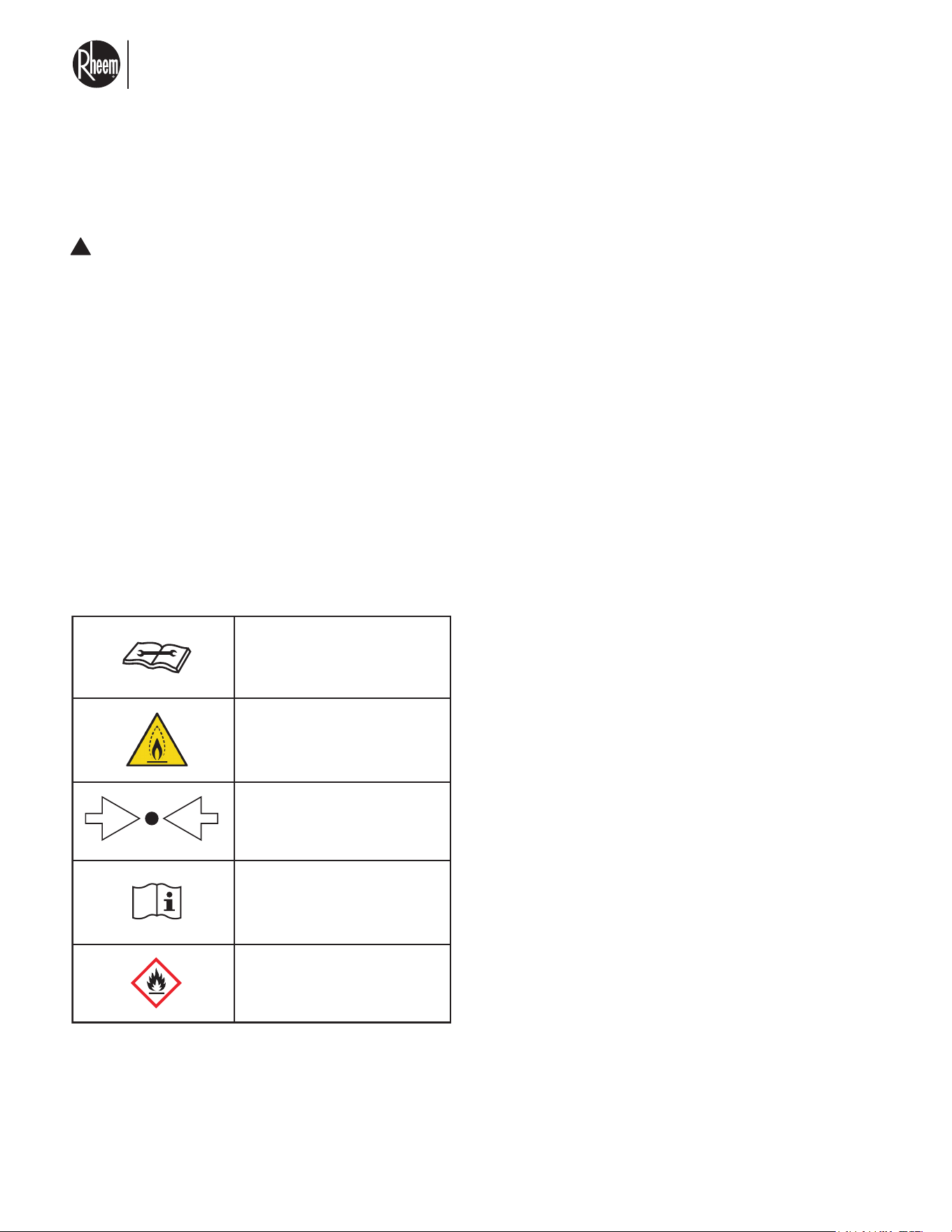
(X) Mpa
Service indicator: read
technical manual
Pressure
Operator’s manual: operating
instructions
Refrigerant Safety Group A2L,
warning; flammable materials
Warning: low burning velocity
material

El nuevo grado de confort.
MR
Commercial HEAT PUMP WATER HEATER MONOBLOCK - I&O MANUAL
Page 7
3.1 IMPORTANCE OF QUALITY INSTALLATION
WARNING:
The heat pump water heater is an electromechanical
machine that incorporates a pressurized refrigerant.
Installation, service, and maintenance must be per-
formed by trained and qualified personnel familiar with
A2L refrigerants and applicable codes.
This manual contains important information on the use,
maintenance, and troubleshooting of your new heat
pump water heater. This unit must be properly installed,
maintained, and operated for optimal performance.
This water heater is designed for the purpose of heating
potable water. Its use in an application other than this
may shorten its life. It is similar in design and operation
to a typical residential air conditioning system. The unit
employs a hermetic motor/compressor operating in a
refrigeration cycle to extract heat from ambient air and
deliver it to the circulating water.
For indirect heating applications, a mixture of water/gly-
col mixed in similar parts is also accepted by the unit.
This unit is equipped with a refrigerant leak detector
for safety. To be effective, the unit must be electrically
powered at all times after installation, other than when
servicing.
WARNING: Unit fan motor might come on un-
expectedly anytime the unit is powered on. This
is due to refrigerant detection system.
As with all heat pump water heaters, compared to other
types of heaters such as gas or oil-fired, this heat pump
water heater has lower heating capacity on a BTUH/
hr basis. As a result, it will be required to operate lon-
ger to accomplish the desired results. It may, at certain
times, operate as much as 24 hours per day. However,
this should not be of concern to the owner, the unit is
designed to operate continuously.
NOTE: Hurricane tie down brackets, tie down
screws, printed warranty and the I&O manual
are located in an accessory bag mounted on the
pallet beside the heater. DO NOT throw away
without removing all components.
WARNING:
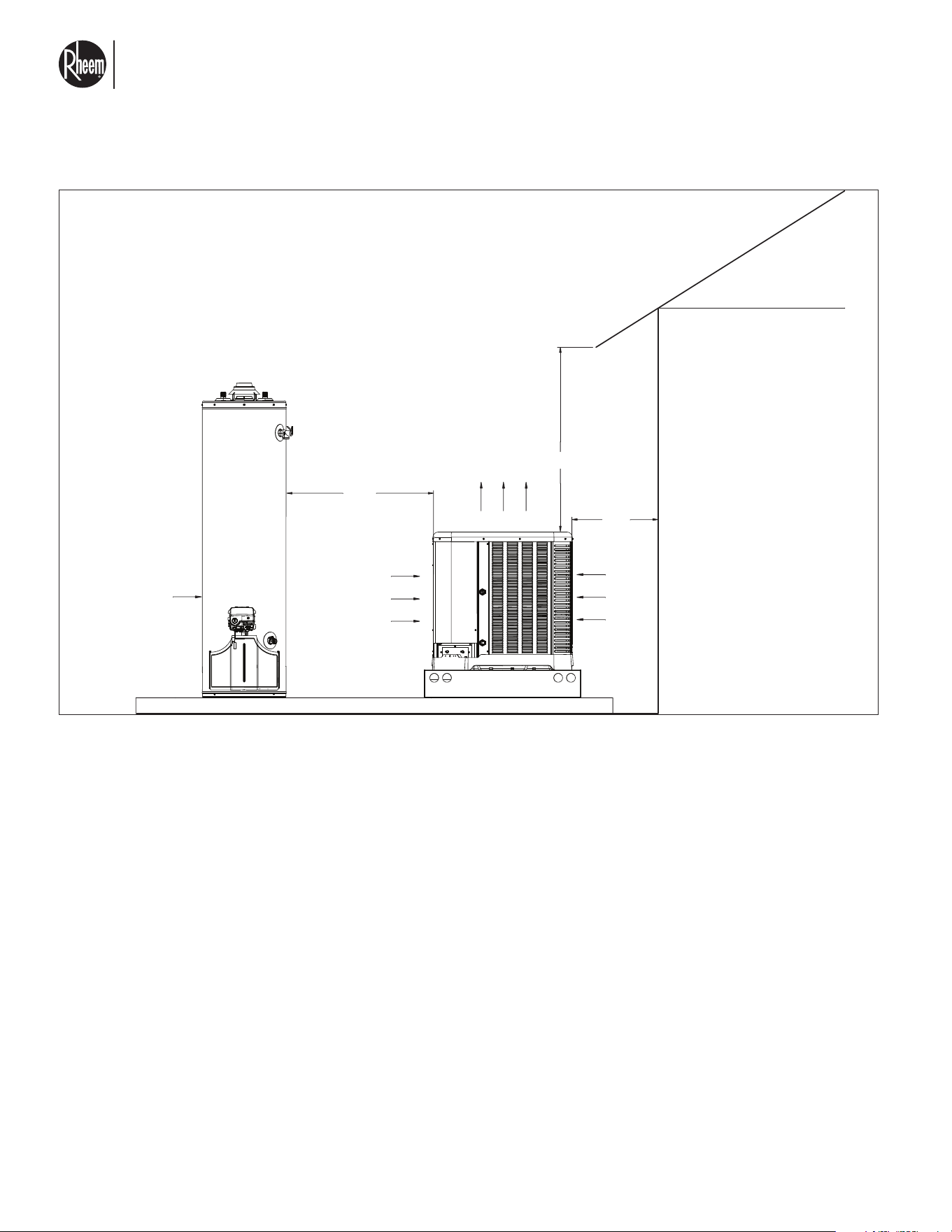
DO NOT install the unit within 6 ft (1.8 m) of
fossil fuel burning heaters. Air intake along
the sides of this heat pump water heater could
disturb the combustion process of the unit, and
could cause damage or personal injury.
Mount the unit on a level, sturdy base, prefer-
ably a concrete slab.
CAUTION: The unit’s supporting base must
be high enough to keep it completely free of
standing water or snow build up at all times.
Situate the heat pump water heater carefully to mini-
mize installation costs while providing maximum effi-
ciency of operation, and to allow adequate service ac-
cess, as follows:
• For unrestricted air intake and service access, po-
sition each side of the unit at least 2 ft (60 cm) from
walls, pipes, and other obstructions.
• On outdoor installations, the unit must sit on a riser
base, that will keep unit above the average snow
line.
• This unit features an ‘up-flow’ discharge. Air is
pulled up through the evaporator coil and dis-
charged through the top grill. Allow at least 5 ft (1.5
m) clearance above the unit for unrestricted air dis-
charge. DO NOT install the unit under a porch or
deck. Recirculation of cold discharge air back into
the evaporator coil will reduce the unit’s heating
capacity and efficiency.
• To minimize water piping, locate the unit as close
as possible to the existing circulator. All pipework
installed must be protected from physical damage
and insulated.
• Rain water run offs - the unit is designed to operate
outdoors and can be exposed to rain. However, rain
water run off falling directly onto the unit can cause
damage and/or shorten the life of your unit. This
may also void your warranty. Install rain gutters or
rain diverters on your roof if the unit is installed in a
position where contact with rain run off may occur.
!
!
!
!
El nuevo grado de confort.
MR
Commercial HEAT PUMP WATER HEATER MONOBLOCK - I&O MANUAL
Page 8
3.1.1 WATER SUPPLY QUALITY
Water quality must be test to be as follows:
Please note that the limited warranty provided with the
water heater does not cover defects, malfunctions or
failures resulting from water conditions that are not in
accordance with the specifications of the table below.
• Size of free floating particles in water needs to be
less than 1 mm [0.039 in]. A use of mesh filter is
recommended to reduce amount of particles.
• pH of water must be tested periodically to ensure is
kept between 7-8, maximum allowed pH is 9.
• Water must be free of Ammonium NH4+, use of
anodes are recommended to keep water free from
this chemical.
• Water hardness must be kept between 20 - 100
mg/L, water softeners are recommended.
• Consider to run a preventive de-scaling cycle at
minimum once a year, This will keep your heater
running at optimal performance. Any commercially
available non corrosive water heater de-scaler is
approved for use.
• When de-scaling, your system must be shut off and
water pipes disconnected from the tanks.
DESCRIPTION QTY.
Sodium [NA] < 20 mg/L
Chloride [CL] < 80 mg/L
Magnesium (Mg] < 10 mg/L
Aluminum [Al] <0.2 mg/L

El nuevo grado de confort.
MR
Commercial HEAT PUMP WATER HEATER MONOBLOCK - I&O MANUAL
Page 9
3.1.2 HEAT PUMP WATER HEATER OVERVIEW
AIR TEMPERATURE
The operating range of the heat pump water heater is
-13°F to 115°F (-25°C to 46°C). Depending on your lo-
cation, you may need additional or back up heating.
Installations where average ambient temperature is ex-
pected to be at or below 20°F requires additional back
up heating.
WATER INLET TEMPERATURE RANGE
The inlet/entering water temperature operating range
for the heat pump water heater is 40 to 135°F. The fac-
tory setting of your heat pump water heater is 140°F.
This water heater is supplied with safety controllers,
temperature, pressure, and other type of sensors.
These must not be altered, removed, or otherwise tam-
pered with. Doing so might impair your heater perfor-
mance, cause malfunction and damage. Damage oc-
curring from sensors removed or modified will not be
covered by warranty.
If replacement sensors are needed, consult your local
Rheem vendor for factory-approved replacements.
REFRIGERANT
The heat pump water heater has a closed loop
refrigerant circuit that is factory-charged with
R-454B refrigerant. It should not be necessary to add
or remove refrigerant during installation or service.
Should it be determined a refrigerate charge adjust-
ment is needed, a qualified installer with proper licens-
ing will be required to charge the unit.
The commercial heat pump water heater is an instanta-
neous type heater, there are no storage tanks integrat-
ed to it, these are sold separately if need. The unit is
designed to allow for both indoor (see section 3.8) and
outdoor (see section 3.3) installation. The heat pump
evaporator extracts heat from ambient air and trans-
fers it to the water. The hot water is moved to the stor-
age tanks via a water circulator (not included). The heat
pump operates in the same way as an air conditioner
and noise is expected when the unit is working.
Even on cold days, your water heater will still continue
to work and heat up the water. Your heater will operate
on ambient temperatures ranging from -13°F to 115 °F,
please notice that during colder days your unit will run
for longer periods of time to achieve the required per-
formance.
OPERATION OF THE UNIT IN FAULT MODE
Your heat pump water heater is sophisticated equip-
ment that has sensors to detect several failure modes.
Upon detecting a failure, the water heater will report
back to the controller device and provide a code of the
failure and description (see section 3.8). The unit will
behave differently, depending on the type of failure.
Consult the troubleshooting section for more informa-
tion.
El nuevo grado de confort.
MR
Commercial HEAT PUMP WATER HEATER MONOBLOCK - I&O MANUAL
Page 10
3.2 MATERIAL AND TOOLS NEEDED FOR
INSTALLING UNIT
TOOLS AND REFRIGERANT
TOOLS REQUIRED FOR INSTALLING AND
SERVICING R-454B MODELS
CAUTION: Use only tools and equipment rated for
A2L refrigerants. Do not use open flames or create
sparks near unit.
DANGER: Risk of fire or explosion. Flammable
refrigerant used. Consult repair manual/owner’s guide
before attempting to service this product. All safety
precautions must be followed.
WORKING PERSONNEL
DANGER: Risk of fire or explosion. Flammable
refrigerant used. To be repaired only by trained service
personnel. DO NOT puncture refrigerant tubing.
Every installation, maintenance, service, and repair
working procedure must be conducted by qualified
personnel who have been trained in operating and ser-
vicing units that employ flammable refrigerants such as
R-454B. Examples of working procedures include but
are not limited to:
• Breaking into the refrigeration circuit
• Opening sealed components
• Opening ventilated enclosures
• Replacing electrical components
• Repairing refrigeration circuits
SPECIFICATIONS OF R-454B
Application: R-454B is not a drop-in replacement for
R-410A. Equipment designs must accommodate the
safety group A2L of R-454B. It cannot be retrofitted into
R-410A units.
R-454B has an atmospheric bubble point of -59.6ºF
and an atmospheric dew point of -58.0ºF [-50.0ºC]. Its
bubble point saturation pressure at 77ºF [25ºC] is 213
psig [1469 kPa] and dew point saturation pressure at
77ºF [25ºC] is 205 psig [1415 kPa].
Pressure: The pressure of R-454B is similar to that
of R-410A. Recovery and recycle equipment, circula-
tors, hoses, and the like must have design pressure rat-
ings appropriate for R-454B. Manifold settings need to
range from 800 psig [5,516 kPa] high-side to 250 psig
[1,724 kPa] low-side with a 550 psig [3,792 kPa] low-
side retard. Hoses need to have a service pressure rat-
ing of 800 psig [5,516 kPa]. Recovery cylinders need
to have a 400 psig [2,758 kPa] service pressure rating,
DOT 4BA400 or DOT BW400.
Flammability: R-454B is classified as safety group
A2L, where the 2L flammability class indicates flam-
mability.
R-454B and air should never be mixed in cylinders or
supply lines or be allowed to accumulate in storage
cylinders. Leak checking should never be done with
a mixture of R-454B and air.
QUICK-REFERENCE GUIDE FOR R-454B
• Ensure that service equipment is designed to oper-
ate with R-454B.
• Refrigerant R-454B operates at pressures similar
to R-410A. However, it is classified in safety group
A2L. Ensure that servicing equipment is compatible
with R-454B.
• Refrigerant cylinders are no longer color-coded.
• R-454B refrigerant cylinders are light green grey in
color with a red band on the shoulder or top of the
cylinder to indicate flammability.
• R-454B, as with other HFCs, is only compatible
with POE oils.
• Vacuum circulators will not remove moisture from
POE oil used in R-454B systems.
• R-454B systems are to be charged with liquid re-
frigerants.
• DO NOT install a suction line filter drier in the liquid
line.
• Desiccant (drying agent) must be compatible for
POE oils and R-454B refrigerant.
!
!
!
El nuevo grado de confort.
MR
Commercial HEAT PUMP WATER HEATER MONOBLOCK - I&O MANUAL
Page 11
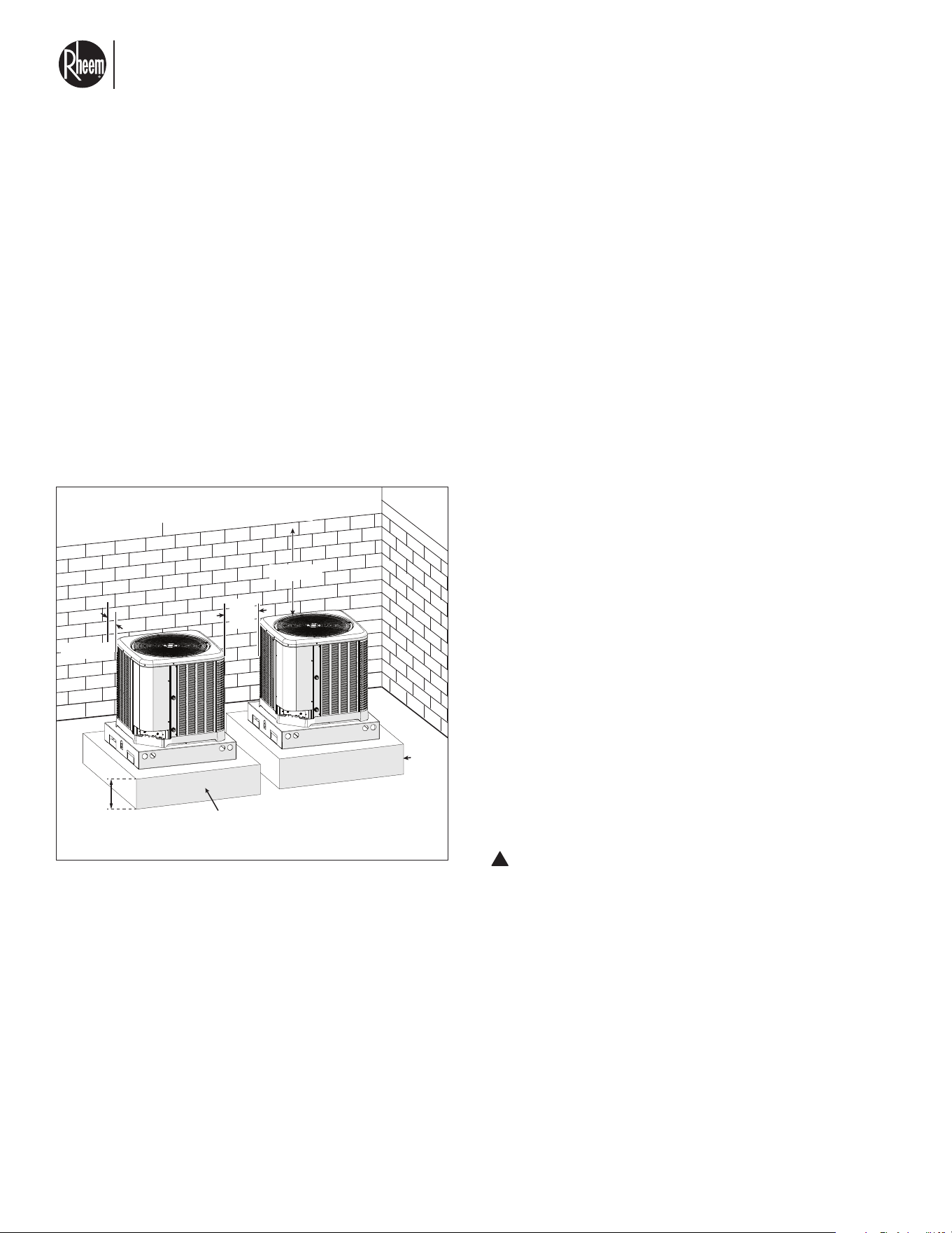
3.3 CLEARANCES FOR INSTALLATION
CHOOSING A LOCATION
ALLOWABLE CLEARANCES
• 24" [61.0 cm] to side intake louvers
• 36" [91.4 cm] between multiple units
• 36" [91.4 cm] to service access panels
• 60" [152.4 cm] vertical for fan discharge
IMPORTANT: Consult local and national building
codes and ordinances for special installation require-
ments. Following location information will provide lon-
ger life and simplified servicing of the outdoor unit.
NOTICE: Units should be installed outdoors where
practically possible. See section 3.8 for indoor installa-
tion considerations.
IMPORTANT: Locate the unit in a manner that will not
prevent, impair, or compromise the performance of
other equipment installed in proximity to the unit. Main-
tain all required minimum distances to gas and electric
meters, dryer vents, and exhaust and inlet openings. In
the absence of national codes or manufacturers’ rec-
ommendations, local code recommendations and re-
quirements will take precedence.
• Locate the unit where water runoff will not create a
problem with the equipment.
• Unit may not be enclosed in a shed or similar.
• Consult rating label for minimum area for installa-
tion.
Units are weatherized, but can be affected by the fol-
lowing:
• Water pouring into the unit from the junction of
roof lines, without protective guttering. Large
volumes of water entering the unit while in op-
eration can impact fan blade or motor life.
• Closely follow the clearance recommendations
on this page.
• Use a concrete slab at least 12" tall to sit the
unit and keep away from water that could
puddle around unit. Concrete slab must be a
square at least 44" long on each side.
CORROSIVE ENVIRONMENT
The metal parts of this unit may be subject to rust or
deterioration if exposed to a corrosive environment.
This oxidation could shorten the equipment’s useful
life.
Corrosive elements include, but are not limited to, salt
spray, fog or mist in seacoast areas, sulphur or chlo-
rine from lawn watering systems, and various chemical
contaminants from industries such as paper mills and
petroleum refineries.
If the unit is to be installed in an area where contami-
nants are likely to be a problem, special attention should
be given to the equipment location and exposure.
• In coastal areas, locate the unit on the side of the
building away from the waterfront.
WARNING: Disconnect all power to unit before
starting maintenance. Failure to do so can cause
electrical shock resulting in severe personal in-
jury or death.
Regular maintenance will reduce the buildup of con-
taminants and help to protect the unit’s finish.
• Frequent washing of the cabinet, fan blade, and
coil with fresh water will remove most of the salt or
other contaminants that build up on the unit.
• A good liquid cleaner may be used several times
a year to remove matter that will not wash off with
water.
ALLOWABLE CLEARANCES
Concrete Base
12”
Min
24” Min
24”
Min
60” Min
36”
Min
!
El nuevo grado de confort.
MR
Commercial HEAT PUMP WATER HEATER MONOBLOCK - I&O MANUAL
Page 12
3.3 CLEARANCES FOR INSTALLATION
CUSTOMER SATISFACTION ISSUES
The outdoor unit should be located away from areas
where noise from the unit would be considered objec-
tionable.
MOUNTING UNIT
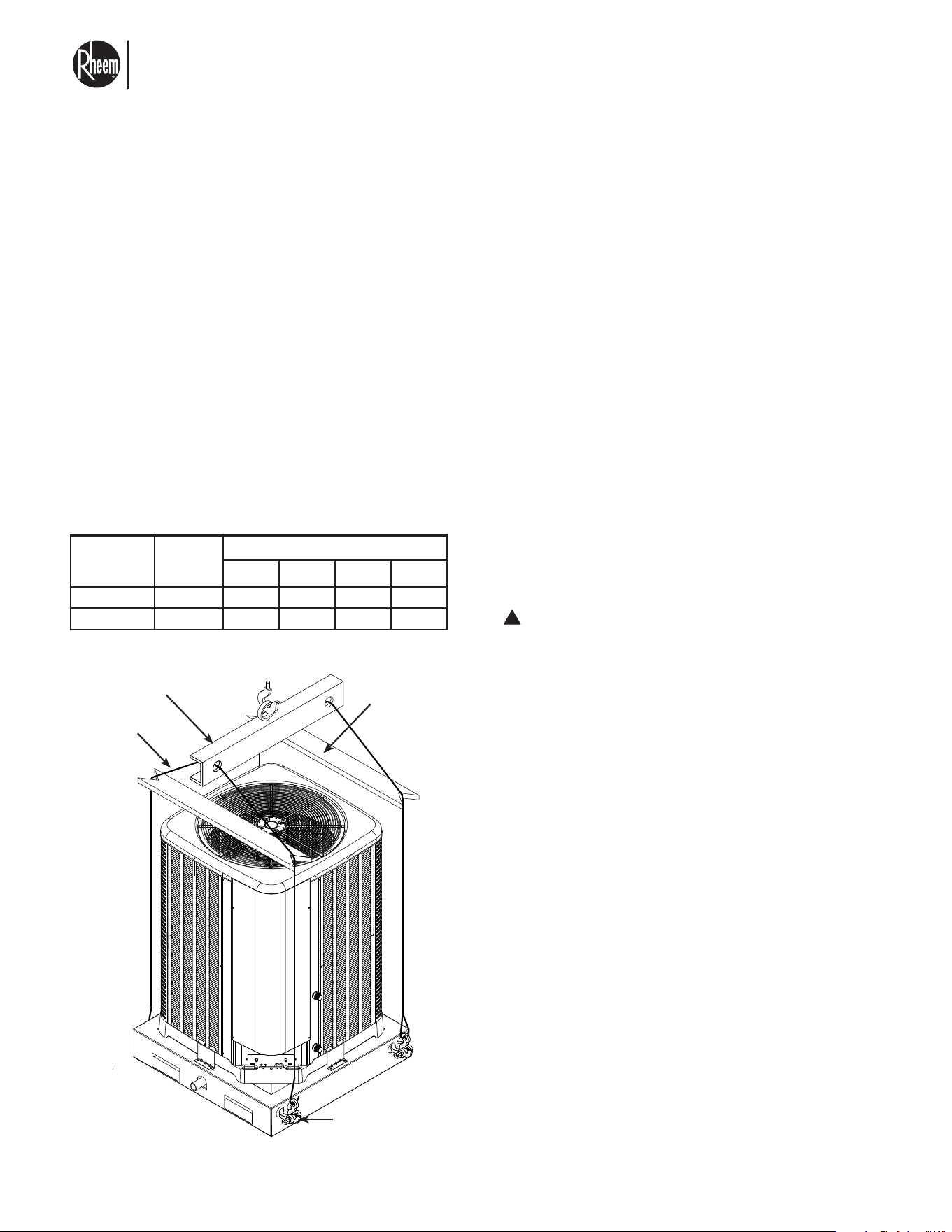
CORNER WEIGHTS AND RIGGING
For lifting unit into place, rig it as shown in the illustra-
tion on the following page, making certain that the rig-
ging slings are of sufficient length to maintain balance
of the unit when it is being lifted. Before placing the
unit on the roof, make certain that the roof structure is
strong enough to support the weight of the unit. Corner
weights are provided in the table below.
LIFTING THE UNIT
HIGH WIND AND SEISMIC TIE-DOWN METHODS
The manufacturer-approved/recommended method is
a guide to securing equipment for wind and seismic
loads. Other methods might provide the same result,
but the manufacturer method is the only one endorsed
by the manufacturer for securing equipment where
wind or earthquake damage can occur. Additional in-
formation is available on the manufacturer's website or
from the wholesale distributor.
ELEVATING UNIT
WARNING: Secure an elevated unit and its elevating
stand in order to prevent tipping. Failure to do so may
result in severe personal injury or death.
If elevating a unit on a flat roof, use 4" x 4" [10.2 cm x
10.2 cm] or equivalent stringers positioned to distribute
unit weight evenly and prevent noise and vibration.
NOTICE: Do not block drain openings on bottom of
unit.
MODEL
TOTAL
WEIGHT
LBS [KG]
CORNER WEIGHT LBS [KG]
A B C D
RMHPHDA068 342 [155] 113 [51] 59.5 [27] 93.5 [42] 76 [34]
RMHPHDA120 458 [208] 156 [71] 78 [35] 121 [65] 103 [47]
!
Spreader Bar
5/8" (16 mm) Shackle
(each corner)
Lifting Beam
A
D
C
B
Cable or Chain
El nuevo grado de confort.
MR
Commercial HEAT PUMP WATER HEATER MONOBLOCK - I&O MANUAL
Page 13
GAS OR
ELECTRIC
WATER
HEATER
6 FT
(1.8 m)
MIN
AIR
FLOW
IN
AIR
FLOW
IN
AIR FLOW OUT
60” (1.52m) MIN
24”
(0.6m)
MIN
Fig. 1: Installation Clearances
It is important to keep the area next to the heat pump
heater clear of shrubs, bushes and chemicals contain-
ers. They could prevent air from circulating fully through
the heat pump heater, and will affect the operation of
the heat pump heater or damage it.
• For high wind or seismic installations requirements
please refer to section 3.6.
3.3 CLEARANCES FOR INSTALLATION
El nuevo grado de confort.
MR
Commercial HEAT PUMP WATER HEATER MONOBLOCK - I&O MANUAL
Page 14
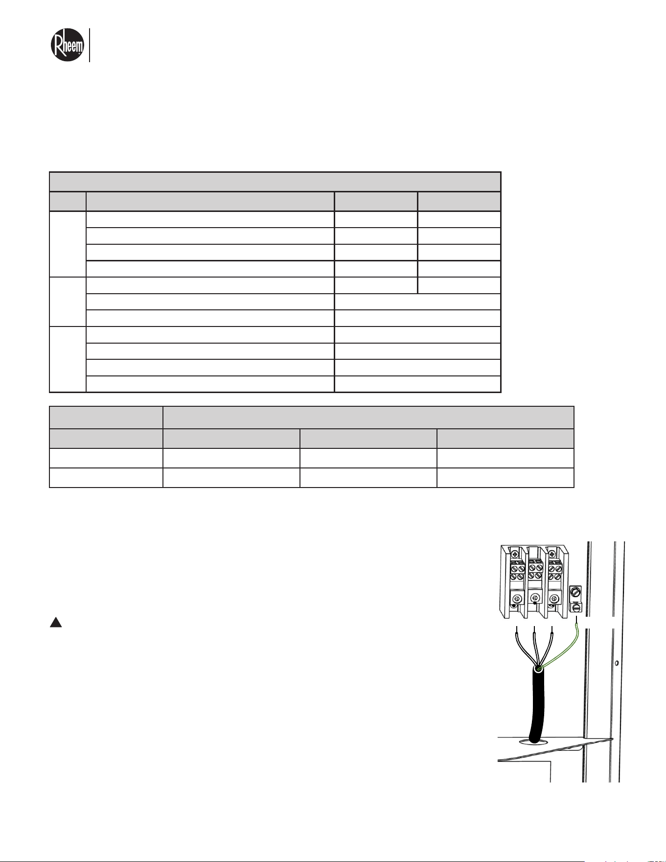
ELECTRICAL DATA
RMHPHDA068 RMHPHDA120
Volts / Frequency / Ø 460/60/3 460/60/3
Rated Load Amps. 25 34
Minimum Circuit Ampacity 33.5 44.8
Rated Overcurrent Protection Device Size 40 50
No. 1 1
Volts 460
Phase 3
Volts 460
Phase 3
HP 1/2
Amps (LRA, each) 2.3
ELECTRICAL DATA
Unit
Information
Compressor
Motor
Fan
Motor
ELECTRICAL CONNECTIONS
Refer to the unit rating plate in the control panel for precise power requirements, ampac-
ity, and over-current protection requirements for your unit.
All wiring must be in accordance with the National Electrical Code, NFPA No. 70, latest
edition, and all applicable state and local codes. See wiring diagram in this Manual.
WARNING:
This unit MUST be installed using flexible conduit for supply wiring to the
unit. This will allow movement of the conduit whenever the junction box is
removed for service - see instructions in this Manual.
• Locate the equipment disconnect means within 3 feet (0.9m) of the heater’s electri-
cal enclosure, or as close to the heater as possible. Always satisfy applicable codes
and standards.
• In sizing power wiring, be especially aware of up-sizing requirements necessary due
to wiring distances. Always satisfy applicable codes and standards.
• Electrical installation should be done by a licensed electrician only.
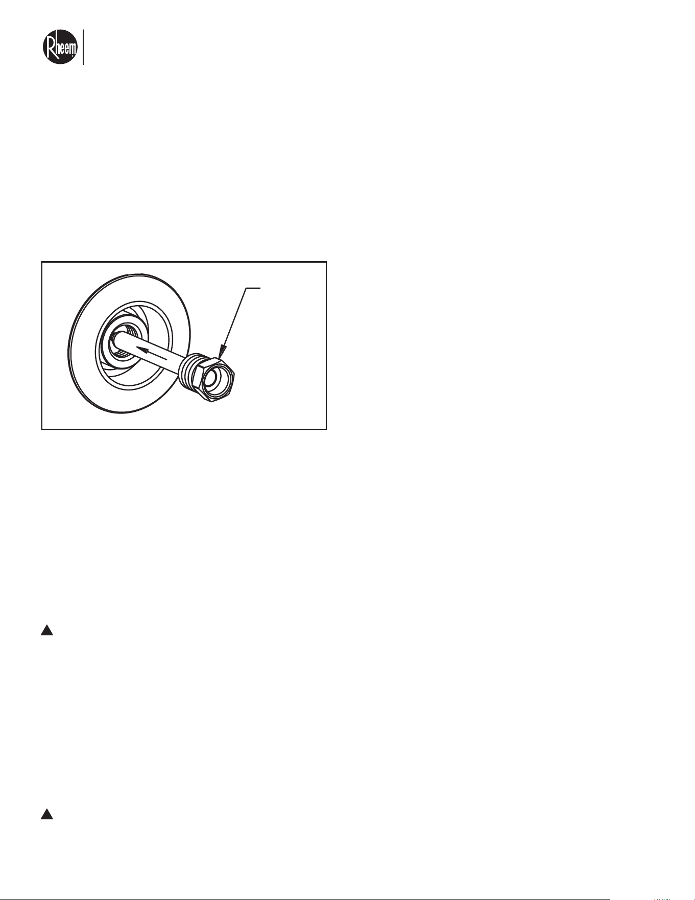
A secondary earth ground lug is located below the water connections. Use this for physical
earth ground.
!
3.4 ELECTRICAL WIRING DIAGRAM AND FIELD
CONNECTIONS
L1 L2 L3
Recommended wire length from breaker to heater, ft [m]. 3% voltage drop max
MODEL No. 10 AWG 8 AWG 6 AWG
RMHPHDA068 100 [30] 190 [58] 300 [91]
RMHPHDA120 75 [23] 142 [43] 225 [69]
Always consult local and national electric standards for recommended wire gauge and lengths.
GND
El nuevo grado de confort.
MR
Commercial HEAT PUMP WATER HEATER MONOBLOCK - I&O MANUAL
Page 15
3.4 ELECTRICAL WIRING DIAGRAM AND FIELD
CONNECTIONS
CONTROL WIRING
WARNING: Turn off electric power at the fuse
box or service panel before making any electri-
cal connections. Also, the ground connection
must be completed before making line voltage
connections. Failure to do so can result in elec-
trical shock, severe personal injury, or death.
A 24-volt, 75 VA minimum transformer is needed to
power external relays, contactors for any external
system circulators, auxiliary heater controllers, 3-Way
valve. The heat pump water heater will ONLY pro-
vide a 24Vac signal to power a relay for the unit
circulator. This relay must be a 24Vac coil.
WARNING: Using the heat pump water heater
24Vac signal to power other devices can damage
the unit transformer and will void warranty.
FIELD WIRE SIZE FOR 24-VOLT CIRCUITS:
Runs up to 100 ft. [30.5 m]: 18 AWG
Runs over 100 ft. [30.5 m]: 16 AWG
NOTICE: Do not use control wiring smaller than 18
AWG between the heat pump water heater and any
external recommended relays, circulator feedback sig-
nals, or others. Temperature sensors can be wired with
up to 20 gauge wire.
!
!
TANK SENSOR INSTALLATION
Install (as shown) one of the supplied temperature sen-
sors into the Sky-35 controller, connect in terminals la-
beled TEMP 1. This sensor is supplier with the Sky-35
controller.
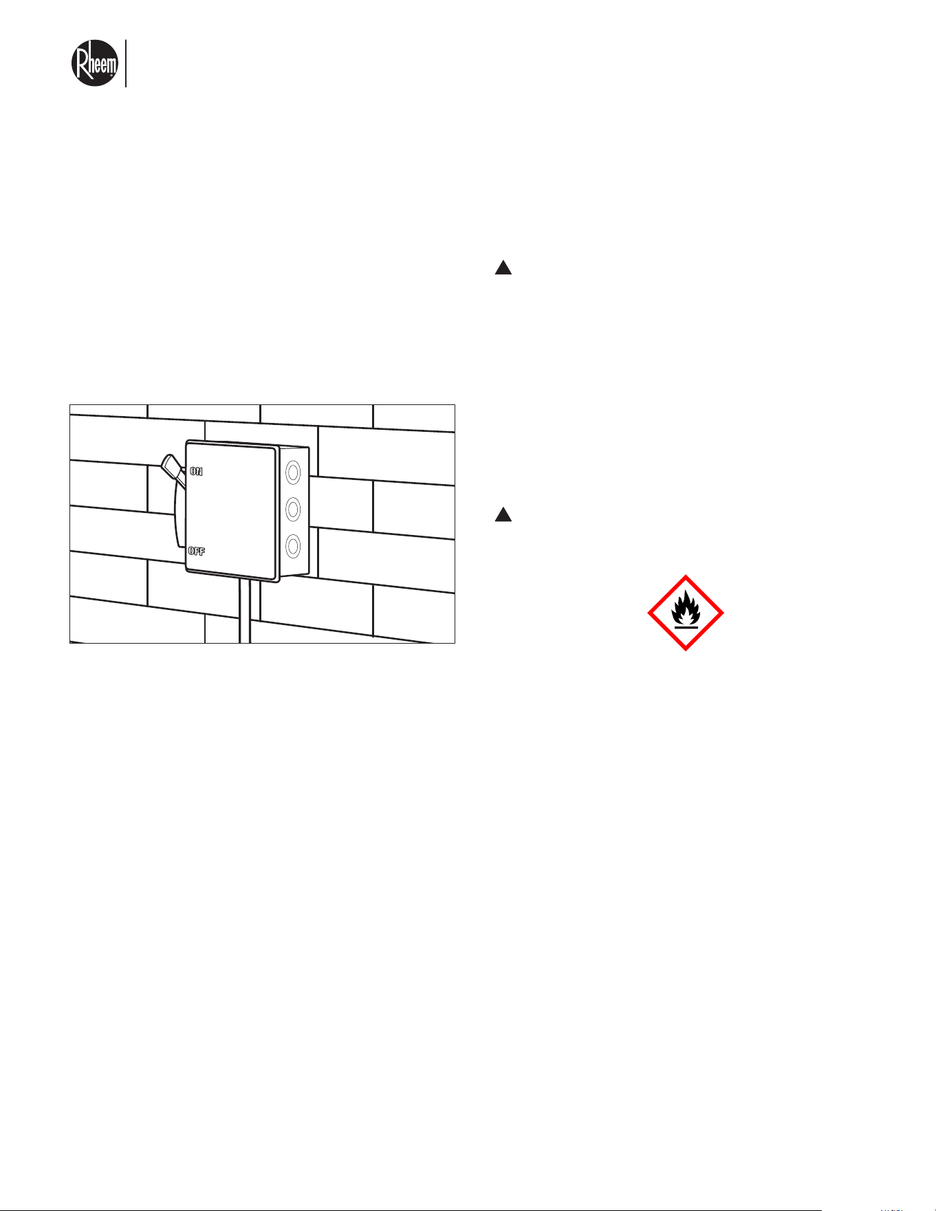
• Insert a Thermostat Well (not supplied) into the
tank. Thermostat Well must be sized to match your
specific tank connector diameter.
• Insert the sensor all the way into the Thermostat
Well and secure it to the storage tank to prevent the
sensor dislodging from the well.
• Cable tie the sensor lead, curling up and tying off
any excess lead.
BUILDING RETURN AND SUPPLY
TEMPERATURE SENSOR
INSTALLATION
• Connect the building return and supply tempera-
ture sensors in the terminals labeled "RETURN
SUPPLY" respectively.
• Run the sensor out to the building flow pipe.
• Fit a Thermostat Well (not supplied) in the pipe en-
suring the end of the sensor is in the flow of water.
To prevent the sensor dislodging from the well, se-
cure the sensor to the insulation using a cable tie.
Alternatively, clamp the sensor to the outside of the
pipe using a pipe clamp prior to the insulation be-
ing fitted.
THERMOSTAT
WELL
El nuevo grado de confort.
MR
Commercial HEAT PUMP WATER HEATER MONOBLOCK - I&O MANUAL
Page 16
POWER WIRING
It is important that proper electrical power from a com-
mercial utility is available at the outdoor unit contactor.
Voltage ranges for operation are shown below.
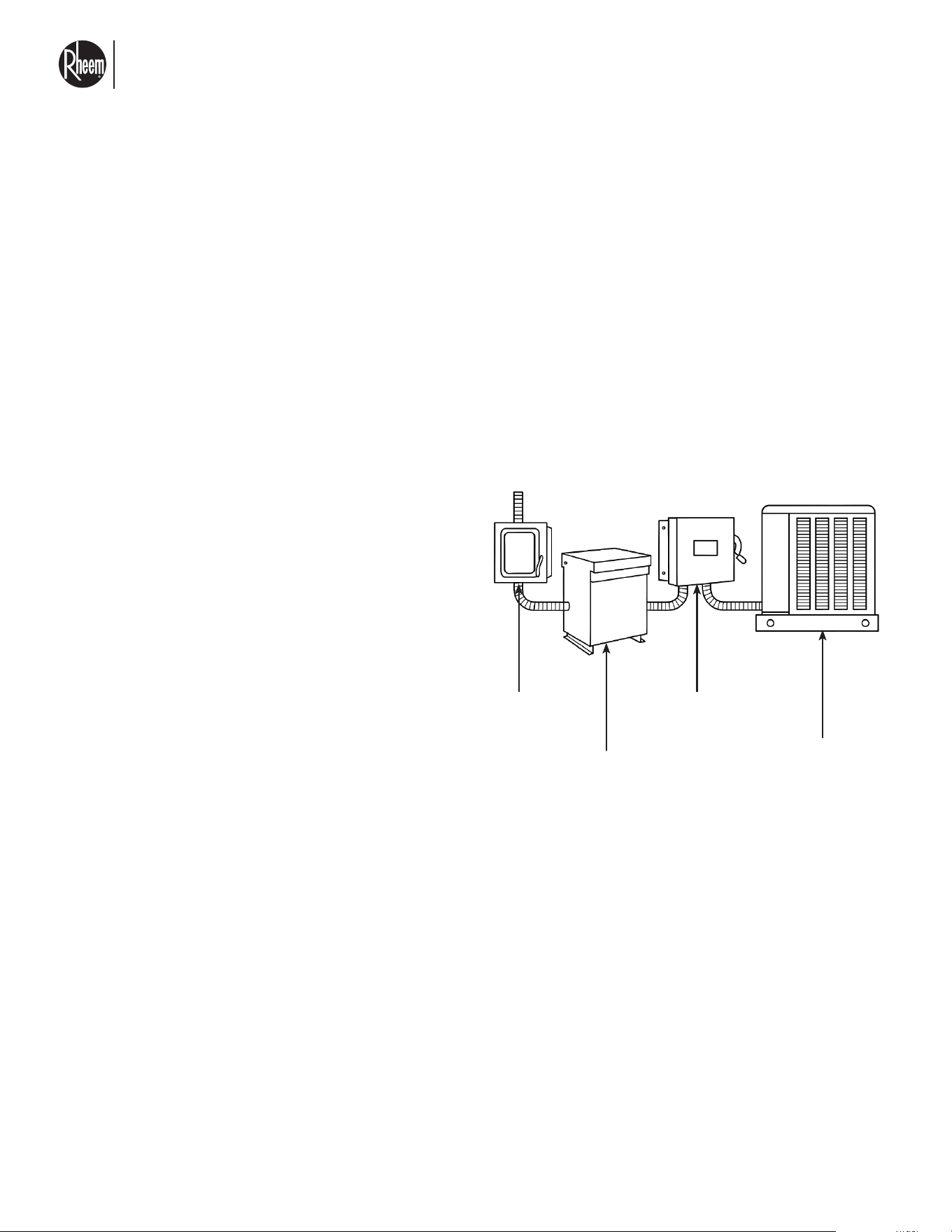
Install a branch circuit disconnect within sight of the
unit and of adequate size to handle the minimum circuit
capacity.
Conduit must be run through the connector panel be-
low the access cover and attached to the bottom of the
control box.
Connect power wiring to line-voltage lugs located in
the unit electrical box.
Check all electrical connections, including factory wir-
ing within the unit, and make sure all connections are
tight.
DO NOT connect aluminum field wire to the contactor
terminals.
GROUNDING
WARNING: The unit must be permanently
grounded. Failure to do so can cause electri-
cal shock resulting in severe personal injury or
death.
A grounding lug is provided for a terminal wire inside
the control box to the right of the main power terminal
block.
A secondary grounding point is added outside the unit
on the panel where the water connections are. This can
be used to secure earth grounding with the base sup-
port or the concrete slab where the unit is mounted.
CAUTION: R-454B is flammable. Failure to
exercise care may result in fire or explosion and
could result in injury or death.
Units run on a 3-phase 460V. Please consult your local
Rheem representative for step up/down transformer
options.
It is recommended that each unit is powered up by a
dedicated transformer to prevent losing multiple units
due to a damaged transformer.
Consult section 2.3 for electrical consumption for each
model.
Power wiring must be run in a rain-tight conduit.
!
!
3.4 ELECTRICAL WIRING DIAGRAM AND FIELD
CONNECTIONS
El nuevo grado de confort.
MR
Commercial HEAT PUMP WATER HEATER MONOBLOCK - I&O MANUAL
Page 17
Heat Pump
Water Heater
Main Breaker,
sized per rating
label on unit
Main Power Dis-
connect to Main
Power Line
Power
Transformer
(if needed)
ELECTRICAL CONNECTIONS
Repair and maintenance to electrical components shall
include initial safety checks and component inspec-
tion procedures. If a fault exists that could compromise
safety, then no electrical supply shall be connected to
the circuit until it is satisfactorily dealt with. This shall be
reported to the owner of the equipment so all parties are
advised.
Review section 7.0 for transformer sizing whenever a
step up transformer is need.
Consult your local electrician or NEC section 450.3(b)
and your local codes for wire sizing and breaker selec-
tion to the main power to the transformer.
The breaker size stated in this manual should be used
as protection only between your heat pump water heat-
er and the transformer or your main power supply. Only
one unit may be powered by the transformer.
Initial safety checks shall include:
• That capacitors are discharged: this shall be done in
a safe manner to avoid possibility of sparking;
• That no live electrical components and wiring are
exposed while charging, recovering, or purging the
system;
• That there is continuity of earth bonding.
3.4 ELECTRICAL WIRING DIAGRAM AND FIELD
CONNECTIONS
TRANSFORMER USED
If your specific application requires a step up transform-
er, refer to section 7.0 for the Rheem suggested part.
Installation of transformer, wiring and breaker sizing to
the main power must be done by a licensed electrician.
The unit will require that a suitable means of disconnect
or breaker is installed between unit and transformer.
Refer to NEC450.3(B) for sizing of transformer to main
power breaker
El nuevo grado de confort.
MR
Commercial HEAT PUMP WATER HEATER MONOBLOCK - I&O MANUAL
Page 18
3.4 ELECTRICAL WIRING DIAGRAM AND FIELD
CONNECTIONS
TRANSFORMER
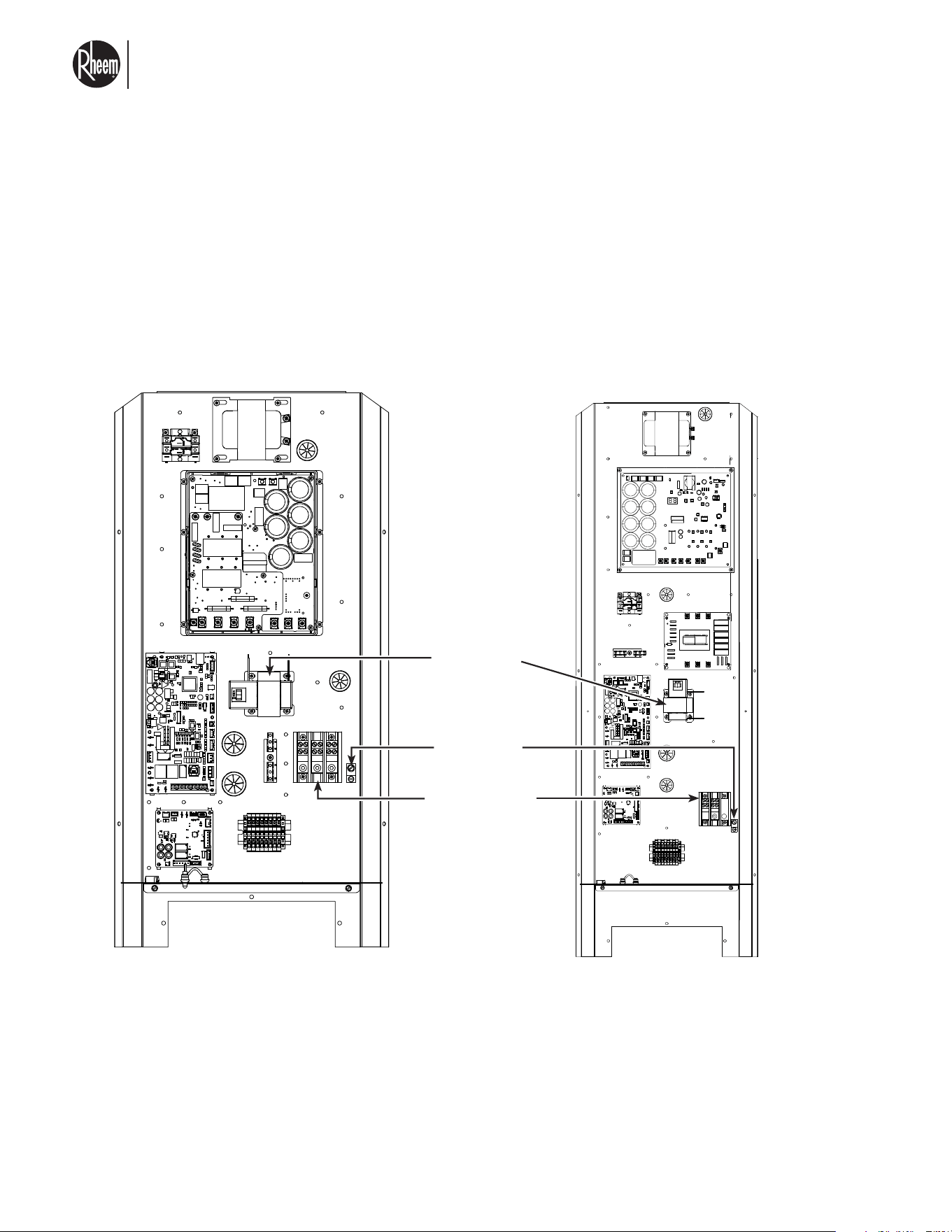
A 75 VA transformer is also provided to feed voltage
to all control boards in the unit, and external relay for
water heater recirculation pump. Transformer is fused
however precautions must be taken to avoid short on
low-voltage connections.
LINE VOLTAGE TERMINAL BLOCK
Terminal block offers connection point for 3 lines
(L1,L2,L3) it accepts up to 6-gauge wire. A ground con-
nector is also provided which accepts up to 6 gauge.
Ground Lug
Terminal Block
Transformer
Control box bracket for RMHPHDA068 Control box bracket for RMHPHDA120
El nuevo grado de confort.
MR
Commercial HEAT PUMP WATER HEATER MONOBLOCK - I&O MANUAL
Page 19
3.4 ELECTRICAL WIRING DIAGRAM AND FIELD
CONNECTIONS
WIRING DIAGRAM SCHEMATIC
RMHPHDA 068 / 120 HEAT PUMP WATER HEATER
COMPRESOR
W
V
U
COMPRESSOR
W
V
U
L1 L2 L3L1 L2 L3
Inverter
Drive
RMHPHDA068
CHOKE
U V W
L
3
L
1
L
2
BK
BK
Inverter
Drive
RMHPHDA068
CHOKE
U V W
L
3
L
1
L
2
BK
BK
YL
BU
RD
COMPRESOR
W
V
U
COMPRESSOR
W
V
U
EMI FILTER
AC-R AC-S AC-TAC-R AC-S AC-TAC-R AC-S AC-T
OUT-
R
OUT-
S
OUT-
T
OUT-
R
OUT-
S
OUT-
T
OUT-
R
OUT-
S
OUT-
T
EMI FILTER
AC-R AC-S AC-T
OUT-
R
OUT-
S
OUT-
T
PE-1
EMI FILTER
AC-R AC-S AC-T
OUT-
R
OUT-
S
OUT-
T
PE-1
Inverter
Drive
RMHPHDA120
STO
N1N2
U
V
W
T
R S
BK
+5 B A GND
4
3
2
1
4
3
2
1
+5 B A GND
4
3
2
1
+5 B A GND
4
3
2
1
CN302CN202
Inverter
Drive
RMHPHDA120
STO
N1N2
U
V
W
T
R S
BK
+5 B A GND
4
3
2
1
CN302CN202
YL
BU
RD
YL
BU
RD
HPS
YL
BU
RD
YL
BU
RD
VT
WH
GND
GND
YL
BU
BK
BR
GND
YL
BU
BU
CONTROL BOARD
J9
J5 J6
P5
P4
P3
P7
P6
P2
P9
P1
1
1
111
1
1
1
1
P11
CONTROL BOARD
J9
J5 J6
P5
P4
P3
P7
P6
P2
P9
P1
1
1
111
1
1
1
1
P11
BK
BK
OR
RD
YL
BK
GY
EEV MAIN
Valve
BK
BK
BK
BK
BK
BK
RD
RD
BK
BK
Sucon Pressure
Transducer
Sucon Pressure
Transducer
RD
GR
BK
Discharge Pressure
Transducer
Discharge Pressure
Transducer
BK
VT
RD
YL
BU
Flammable
refrigerant
sensor
7 6 5
4
7 6 5
4
7 6 5
4
3
Flammable
refrigerant
sensor
7 6 5
4
3
YL
BU
OR
BK
BR
BR
J1
J7
J11
J4
J5
J6
J10
J9 J3
J2
J8
EXPANSION
BOARD
J1
J7
J11
J4
J5
J6
J10
J9 J3
J2
J8
EXPANSION
BOARD
3
WFS
BU BR
OR
RD
YL
BK
GY
YL
BU
VT
** See manual for other pump types
TB-EXT
1 2 4
3 5 6
1 2 4
3 5 6
1
2
43 5
6
1
2
43 5
6
TB-EXT
1 2 4
3 5 6
1
2
43 5
6
SKY-35
Controller
SKY-35
Controller
TB-EXT
1 2 4
3 5 6
1
2
43 5
6
SKY-35
Controller
** See manual for other pump types
TB-EXT
1 2 4
3 5 6
1
2
43 5
6
SKY-35
Controller
BR
BU
BU
RD
RD
GR
BU
OR
WH
BK
YL
RD
Coil temp sensor
Sucon temp sensor
Ambient temp sensor
Vapor in temp sensor
Vapor out temp sensor
Defrost valve coil
Water out
temp sensor
Water in
temp sensor
EEV Vapor
Injecon
Discharge temp sensor
RD WH
BK
GR
POWER SUPPLY:
460V – 3 PHASE – 60Hz
24VAC 460VAC
24VAC
TRANSFORMER
TB24
YL
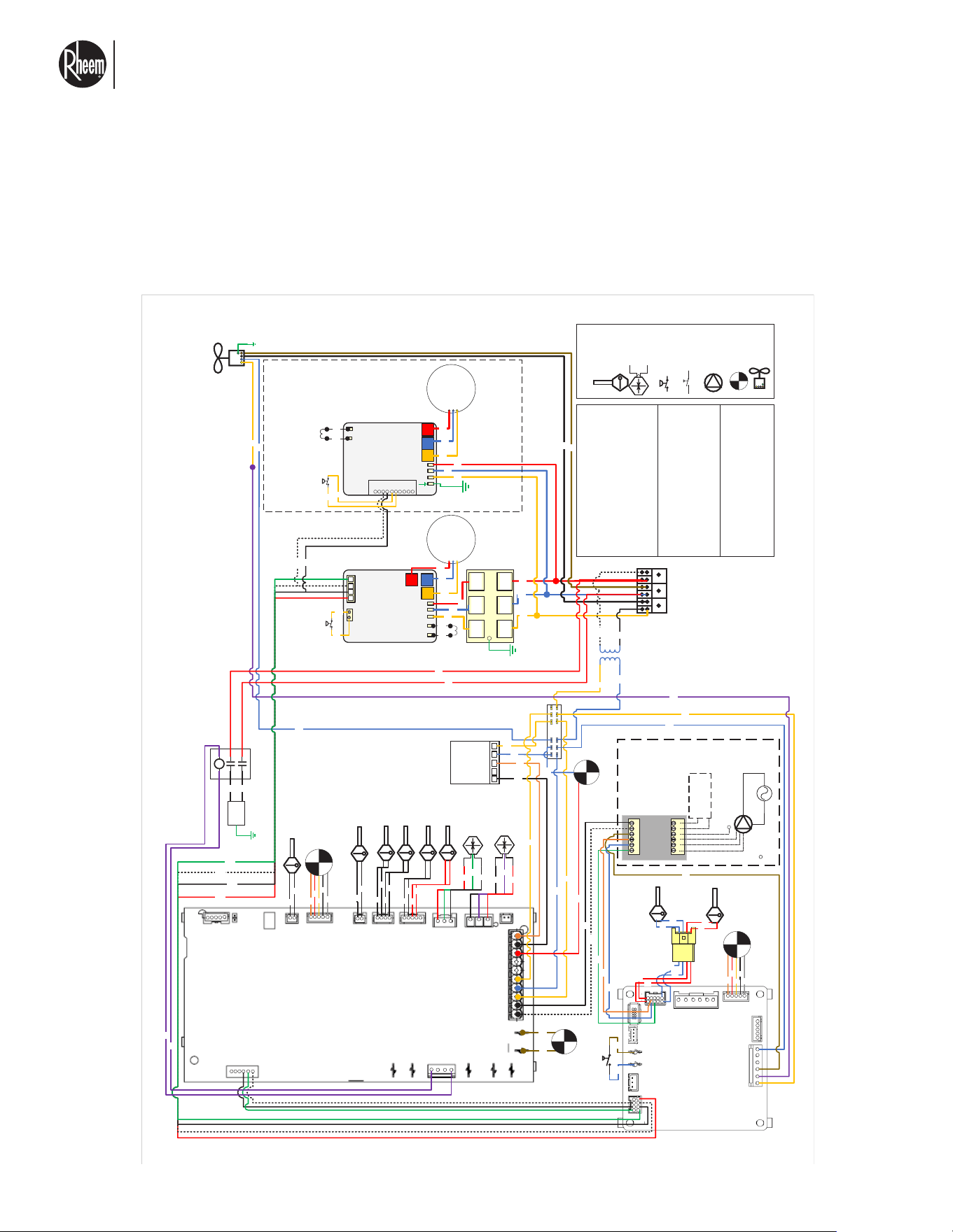
WIRING DIAGRAM RMHPHDA 068/120 HEAT PUMP WATER HEATER
Switch
(Normally Open)
Temperature
sensor
Pressure
Transducer
Pressure
Transducer
Switch
(Normally Closed)
PumpPump
Fan
Valve
SENSOR CODE
Switch
(Normally Open)
Temperature
sensor
Pressure
Transducer
Switch
(Normally Closed)
Pump
Fan
Valve
SENSOR CODE
WIRE COLOR CODE
RD – RED BK – BLACK
VT – PURPLE WH – WHITE
GR – GREEN BU – BLUE
BR – BROWN YL – YELLOW
OR – ORANGE GY – GRAY
COMPONENT CODE
GND GROUND
HPS High Pressure Switch
WFS Water Flow Switch
TB24 24VAC Terminal block
TB-EXT Terminal Block For External components
CCH Crankcase Heater
90-109727-01
CHOKE
BK
12V
COM
A
B
5V
HPS
5V
DLT
AI
COM
WH
BK
HPS
YL
YL
*Only on RMHPHDA068 Model
* 2 wires are used for communicaon
From connector J8 of Expansion board
CCH Relay
5
2
3
6
1
4
CCH
BK
BK
GND
VT
VT
RD
RD
TERMINAL BLOCK FOR EXTERNAL COMPONENTS
1.Ground signal (use for variable speed pump control
or for single speed pump relay) (-)
2. Variable speed pump feedback signal (oponal)
3. Variable speed pump control signal (+)
4. Single speed pump control (24VAC)
5. Sky 35 communicaon signal (+)
6. Sky 35 communicaon signal (-)
YL
**UNIT PUMP
External variable
speed pump
External variable
speed pump
External
power
by others
BU
Vapor injecon
valve coil
1
1
1
1
1
BU
BU
RD
RD
El nuevo grado de confort.
MR
Commercial HEAT PUMP WATER HEATER MONOBLOCK - I&O MANUAL
Page 20
3.5 SKY-35 CONTROLLER FOR MULTIPLE
HYDRONIC HEAT SOURCES
ACCESSORIES INCLUDED
• Supply temperature sensor
• Return temperature sensor
• Outdoor temperature sensor
SKY-35 CONTROLLER SPECIFICATIONS
Rated Voltage /
Frequency / Phase
24V / 60Hz
Total Load
(less circulators)
10VA / 0.42 A
Weight 3.2 lb / 1.45 kg
Max Fuse Size 2 A
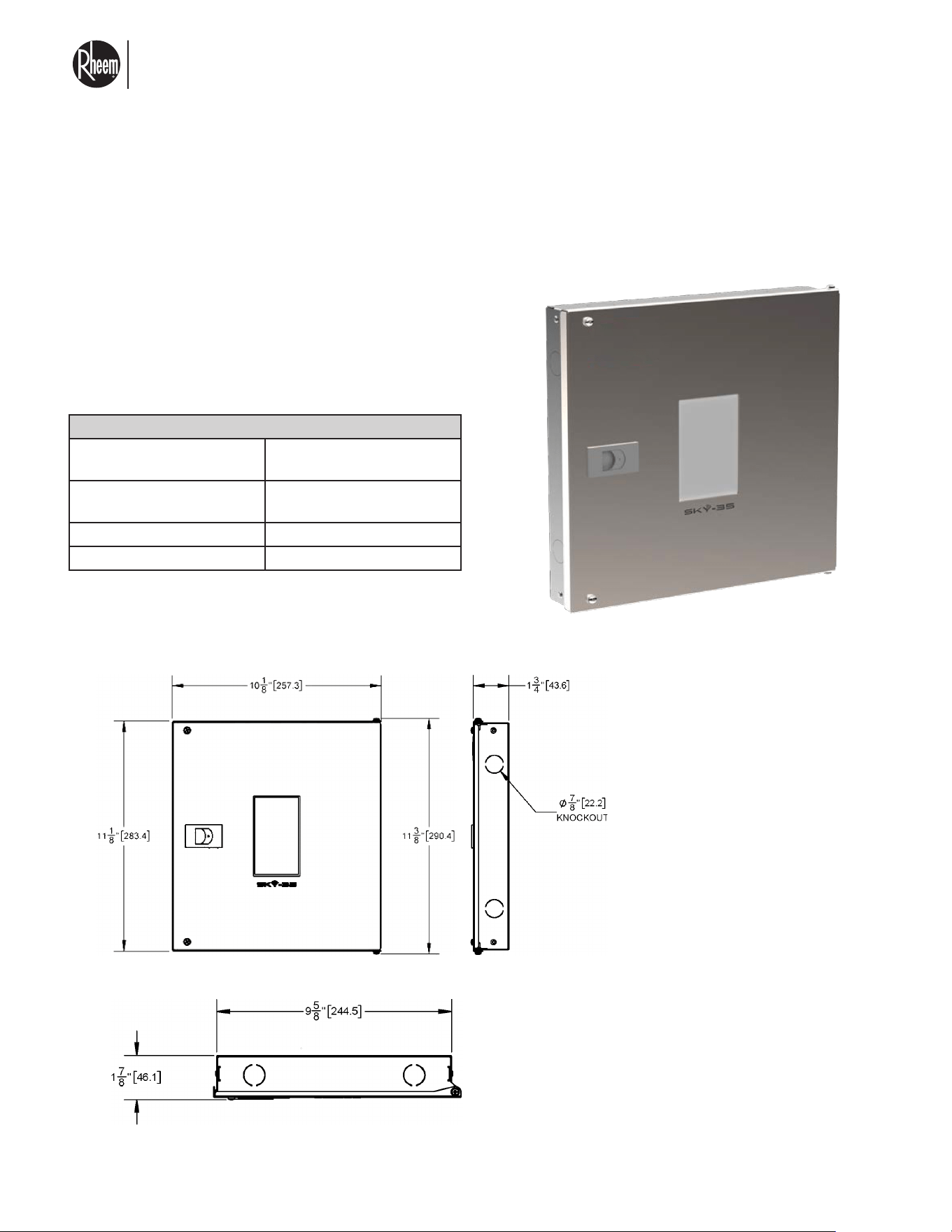
DIMENSIONS
Your new heat pump water heater requires a controller device, sold separately, in order to operate to its full potential.
This controller will allow you to operate your device with various configurations, auxiliary tanks, and multiple units.
NOTE: An external 24Vac
transformer is required to
power up the device. Do
not power the device us-
ing voltage from your heat
pump water heater. Doing
so can damage your unit
and void warranty.
Fig. 2: Front view of Sky-35 Controller Fig. 3: Side view of Sky-35 Controller
Fig. 4: Top view of Sky-35 Controller
El nuevo grado de confort.
MR
Commercial HEAT PUMP WATER HEATER MONOBLOCK - I&O MANUAL
Page 21
1 2 3 4 5 6 1 2 3 4 5 6 1 2 3 4 5 6 1 2 3 4 5 6
3.5 SKY-35 CONTROLLER FOR MULTIPLE
HYDRONIC HEAT SOURCES
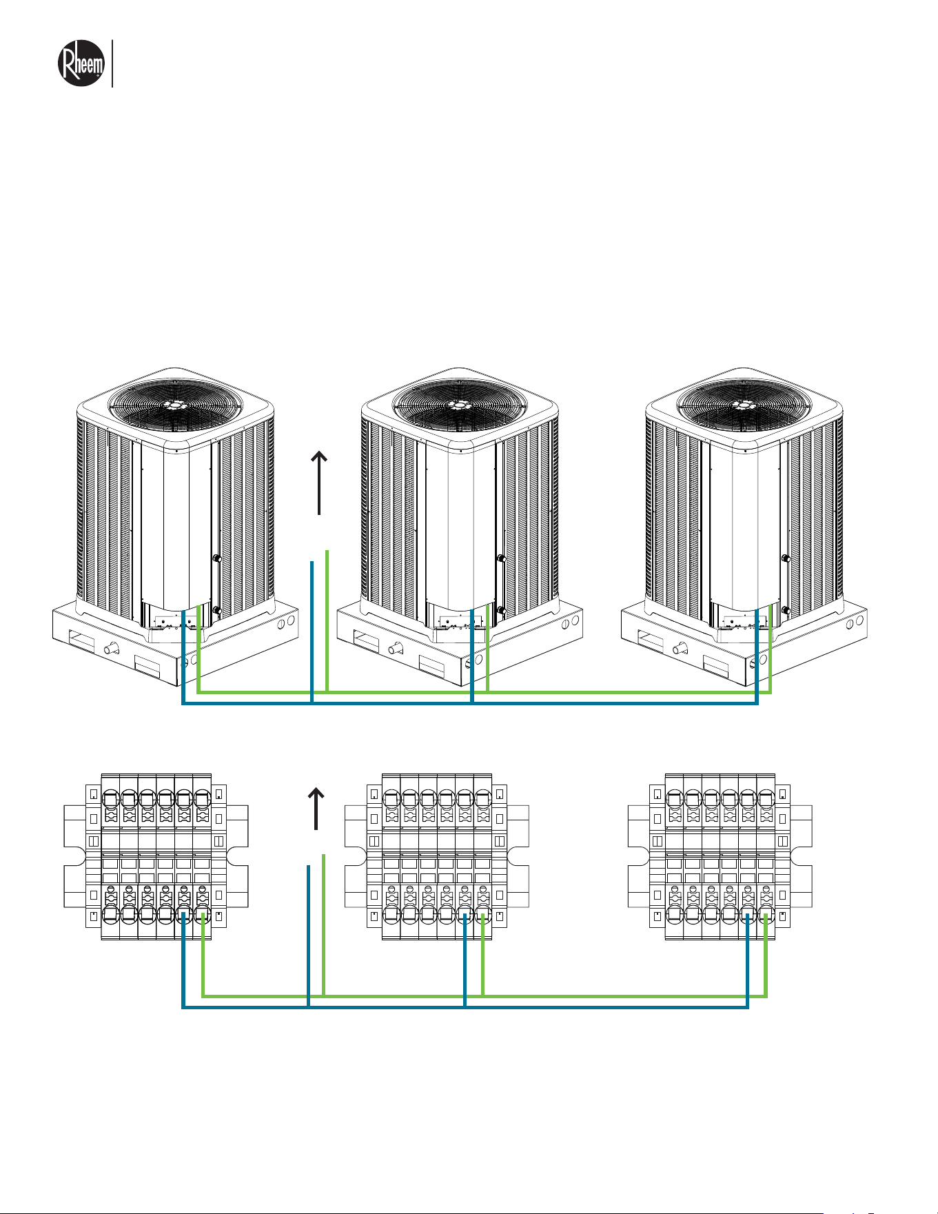
RS-485 CONNECTIONS
Heat pump water heaters are connected to the main
controller device (Sky-35) via the RS-485 ports E1 and
E2 (7,8) on the heat pump and ports A, B on the Sky-35.
Multiple units can be daisy chained, up to 16 units can
be connected to the Sky-35 device.
A B
To Sky-35
ports A, B
To Sky-35
ports A, B
A B
El nuevo grado de confort.
MR
Commercial HEAT PUMP WATER HEATER MONOBLOCK - I&O MANUAL
Page 22
R C
1 2 3 4 5 6 1 2 3 4 5 6
1 2 3 4 5 6
1 2 3 4 5 6
S
S
1 2 3 4 5 6 1 2 3 4 5 6
3.5 SKY-35 CONTROLLER FOR MULTIPLE
HYDRONIC HEAT SOURCES
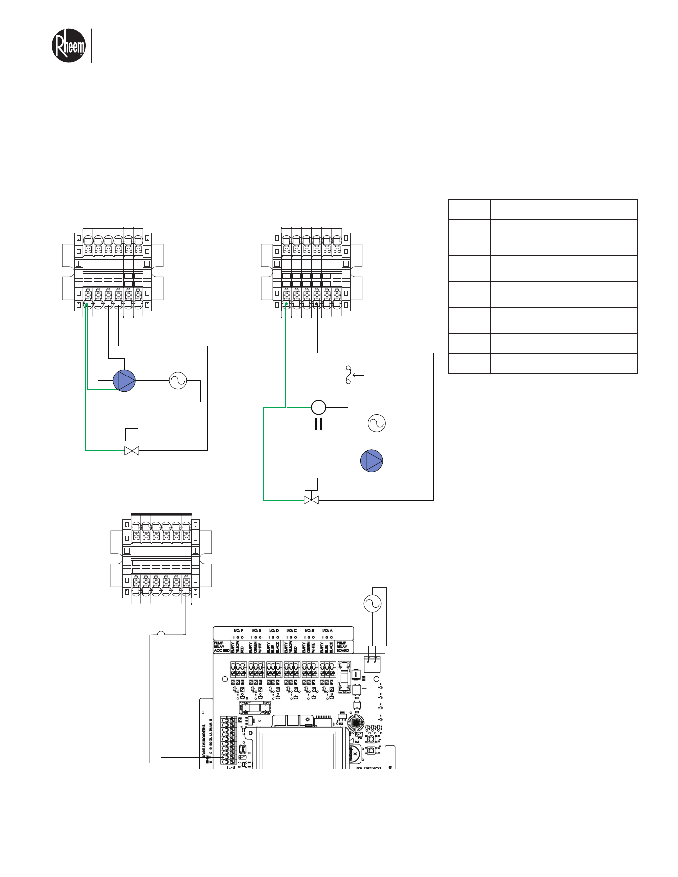
EXTERNAL COMPONENTS DIAGRAM
External power
by others**
Water inlet Solenoid valve.
See piping diagram for details.
Water inlet Solenoid valve.
See piping diagram for details.
Fuse 1
amp Max
24Vac
relay*
External power
by others**
External single
speed circulator
24Vac
Power external***
External variable
speed circulator
PORT DESCRIPTION
1
Ground signal (use for variable
speed circulator control or for
single speed circulator relay) (-)
2
Variable speed circulator feedback
signal (optional)
3
Variable speed circulator control
signal (+)
4
Single speed circulator control
(24Vac)
5 Sky-35 communication signal (+)
6 Sky-35 communication signal (-)
* External relay not provided, relay must be a 24Vac coil, 3/4 watt max.
** External power must match circulator voltage, please consult your circulator user manual for voltage and wiring diagrams.
*** External power supply 24Vac at 75 Watts.
Circulators are available via your local Rheem distributor, consult your Rheem representative.
El nuevo grado de confort.
MR
Commercial HEAT PUMP WATER HEATER MONOBLOCK - I&O MANUAL
Page 23
3.5 SKY-35 CONTROLLER FOR MULTIPLE
HYDRONIC HEAT SOURCES
CLEARANCES
When wall-mounting, leave adequate room for door
swing, wiring connections, and 6" (15 cm) below for in-
sertion of USB stick.
SKY-35 CONTROLLER OVERVIEW
The controller provides easy and versatile manage-
ment of multiple hydronic heat sources. The Sky-35 al-
lows you to set up primary and backup heat sources so
that they work together in a priority sequence.
FEATURES OF THE CONTROLLER
• Main loop monitoring and control
• Buffer tank monitoring with summer shutdown
• Always-on status display
• Easy-to-set outdoor reset control option
• Dry contacts for control of third-party heat sources
• Easy heat source setup
• Supply, return, and outdoor temperature sensors
included
• Heat pump over-temp protection
• Heat pump freeze protection
• Flexible options for a wide spectrum of hydronic
applications
POWER-UP SEQUENCE AND
OPERATIONAL STATES/CYCLES
When the Sky-35 is first energized, some settings will
already be populated with default values: you will prob-
ably wish to change (and Save) certain settings. Gener-
ally, saved values take effect with the next heating (or
cooling) call.
After a power interruption, the controller automatically
resumes operation with all the previously stored values,
including any changes you have made. During a power
interruption a capacitor maintains the clock operation,
but the capacitor charge is not required for retention of
saved changes.
Consult the manual provided with the Sky-35 for details
on system set up and operation.
LOCATION
Situate the controller in the heating equipment room
approximately 5 ft (1.5 m) from the ground, or at a
height offering easy access. Before mounting, consider
accessibility to heat sources and circulators which are
to be wired to the controller. Leave adequate room for
door swing, wiring connections, and 4" (10 cm) below
for insertion of USB stick.
CIRCULATOR RELAY MODULE CONNECTIONS
Supply power wiring
knock-out (1)
1/2"
Circulator wiring knock-
outs (7)
1/2"
El nuevo grado de confort.
MR
Commercial HEAT PUMP WATER HEATER MONOBLOCK - I&O MANUAL
Page 24
3.5 SKY-35 CONTROLLER FOR MULTIPLE
HYDRONIC HEAT SOURCES
TERMINAL FUNCTIONS AND RATINGS
BLOCK PIN TYPE DESCRIPTION MAXIMUM RATING
R C Input
24Vac power to the Sky-35 controller from
Circulator Relay Module
24 VAC
I/O:
CIRCULATOR A-F
O Output
EMC / PSCCirculator Control; 12V -PWM
control signal relative to G terminal
150 mA; 400 mA
total A-F
I Input
EMC / PSCCirculator Feedback; 5 to
24 V-PWM relative to G terminal
G Output
With O terminal can connect to Circulator
Relay Module for standard PSC circulator
control
Thermostat
Input Room
thermostat
connection
A
RS485 comms interface for intelligent
thermostats compatible with IBC
DO NOT APPLY
POWER
B
Heat Source
1 (HP) Heat Pump
demand terminal
block
ON_OFF
(2)
Dry contacts
To initiate a call for heat pump operation
(like TT)
24Vac/DC
HT_CL
(2)
Dry contacts
For heat pump to select heating or cooling
mode (like TT)
24Vac/DC
DEF + (2)
Input,
isolated 24V
Defrost signal from heat pump 24Vac/DC
A
RS 485 comms interface for IBC heat
pumps
DO NOT APPLY
POWER
B
Heat 2 (EB) Electric
boiler demand
terminal block
A
RS 485 comms interface for IBC electric
boilers
DO NOT APPLY
POWER
B
T (2) Dry contacts
To initiate a call for electric boiler opera-
tion
24Vac/DC
Heat 3 (GB) Gas
Boiler demand
terminal block
T (2) Dry contacts To initiate a call for a gas boiler operation 24Vac/DC
DEV_1 T (2) Dry contacts
Terminal block for auxiliary device 1
control [upcoming feature]
24Vac/DC
DEV_2 T(2) Input
Terminal block for auxiliary device 2
control [upcoming feature]
24Vac/DC
TEMP_1 (2) Input
Terminal block for auxiliary NTC
10KΩ thermistor as Temperature Sensor 1
DO NOT
APPLY
POWER
TEMP_2 (2) Input
Terminal block for auxiliary NTC
10KΩ thermistor as Temperature Sensor 2
DO NOT
APPLY
POWER
El nuevo grado de confort.
MR
Commercial HEAT PUMP WATER HEATER MONOBLOCK - I&O MANUAL
Page 25
3.5 SKY-35 CONTROLLER FOR MULTIPLE
HYDRONIC HEAT SOURCES
BLOCK PIN TYPE DESCRIPTION MAXIMUM RATING
TEMP_3 (2) Input
Terminal block for auxiliary NTC
10KΩ thermistor as Temperature Sensor 3
DO NOT
APPLY
POWER
TEMP_4 (2) Input
Terminal block for auxiliary NTC
10KΩ thermistor as Temperature Sensor 4
DO NOT
APPLY
POWER
RETURN (2) Input
Terminal block for supplied NTC
10KΩ thermistor as Return Temperature
Sensor
DO NOT
APPLY
POWER
SUPPLY (2) Input
Terminal block for supplied NTC
10KΩ thermistor as Supply Temperature
Sensor
DO NOT
APPLY
POWER
OUTDOOR (2) Input
Terminal block for supplied NTC
10KΩ thermistor as Outdoor Temperature
Sensor
DO NOT
APPLY
POWER
TERMINAL FUNCTIONS AND RATINGS
*Output Load Control 24 VAC / VDC; 5.0 A; Resistive. 24 VAC @ 24 VA; 1.0 A; 3.6 A Inrush; Pilot.
El nuevo grado de confort.
MR
Commercial HEAT PUMP WATER HEATER MONOBLOCK - I&O MANUAL
Page 26
3.6 ANCHOR INSTRUCTIONS FOR HIGH WIND
LOCATION
GROUND MOUNT TO CONCRETE
1. All existing supporting host concrete shall have
f'c=3,000 psi min. compressive strength and shall
be regular-weight, uncracked concrete, design and
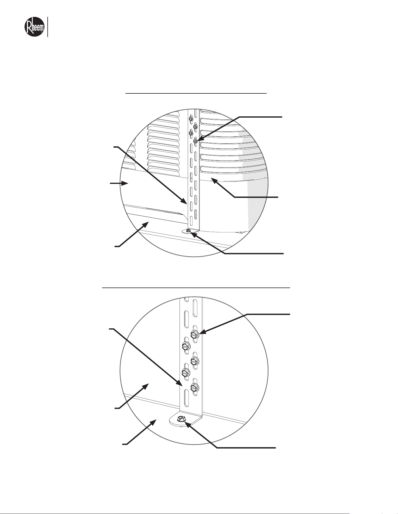
integrity by others.
2. "Stand Rail" where used here refers to equipment
stand rail members, design and integrity by others,
which shall be 0.090" min. thick, 6061-T6 or stronger
aluminum OR 12 GA (.098") min. thick, ASTM A653
Gr. 33 min. (Fy=33 ksi min, Fu=45 ksi min) galv. steel.
3. "Tie-Down Clip" or "Clip" where used herein: Each
clip shall be 1" min. wide x 0.068" min. thick, UTS
= 45 ksi min. (equivalent to ASTM A653 Gr. 33 or
stronger) galv. steel, typ. Ensure clip sits flush on
host structure and flush against the unit. Clip-to-unit
screws shall be positioned as (1) screw per clip slot,
typ. Care must be taken to avoid screw contact with
internal piping and components; exercise caution
with screw installation.
4. "Sheet Metal Screws" or "SMS" where used herein:
screws shall be SAE Gr. 2 min. or SS self-drilling
screws with washers, typ.
5. "Thru-Bolt" where herein: bolt shall be a UNC bolt,
SAE Gr. 2 min. or SS, with 1" min. OD fender wash-
ers and ID sized for the bolt shank diameter at the
top and bottom of the connection (under the bolt
head and above the locking nut), and SAE Gr. 2
min. or SS locking nut at the underside of the con-
nection, typ. See the thru-bolt diagram on the sec-
ond-to-last page of this report.
6. A total of 8 tie down brackets and hardware for in-
stallation are included with the unit. These are in-
tended for secure of unit at 54 psf. If more brack-
ets and hardware are need, these can be obtained
via Rheem replacement parts. Consult your local
dealer. These can be ordered with the part number
10-105931-02.
FRONT
SIDE
RIGHT
SIDE
LEFT
SIDE
BACK
SIDE
GROUND MOUNT TIE-DOWN DIRECTIVE
SCALE: NTS TOP VIEW
3 ksi HOST CONCRETE
BY OTHERS
Bottom Steel Pallet
Water
Connections
Clip Attachment,
Typ.
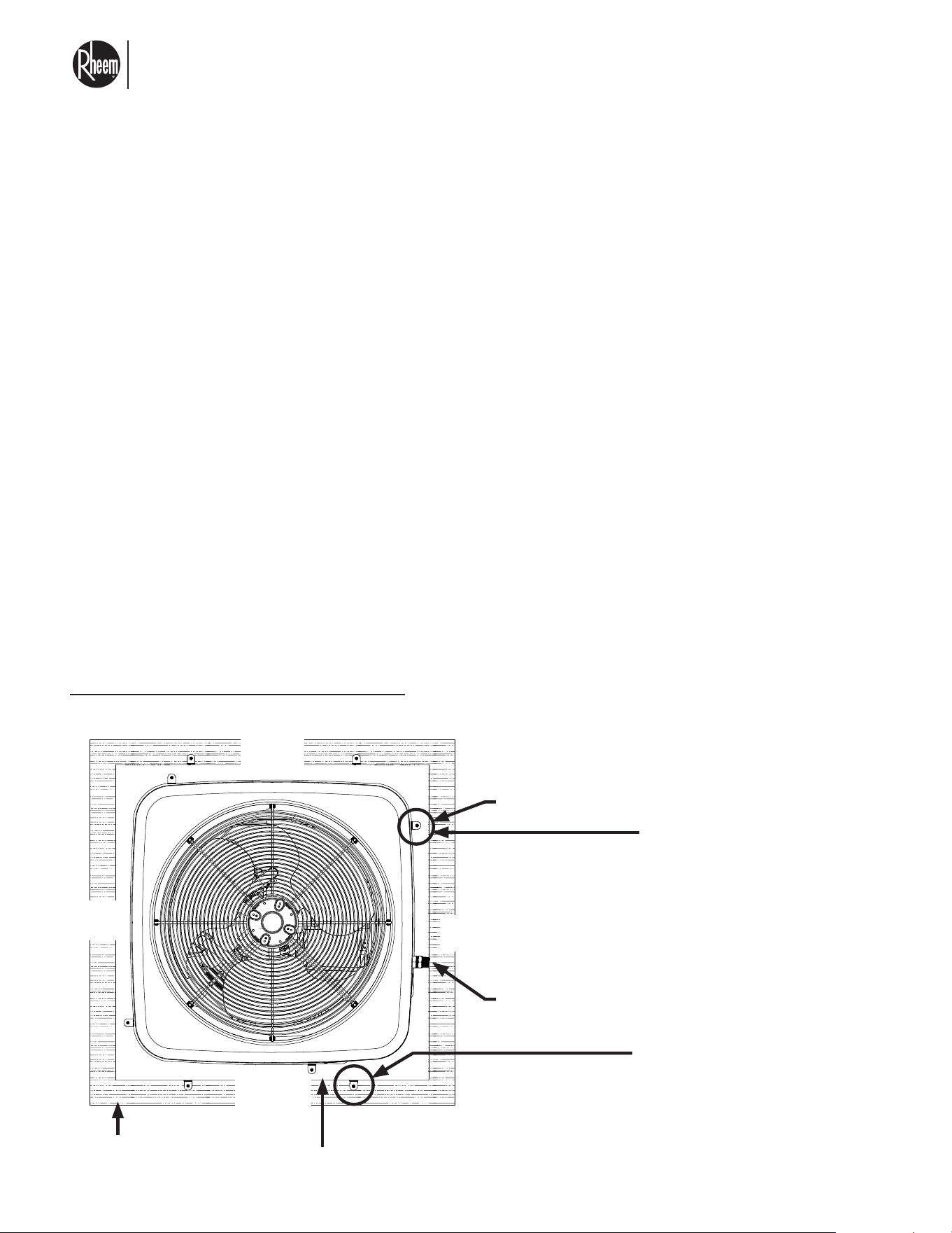
Valid for ASD Wind Pressure up to ± 54 psf Lateral & 0 psf Uplift. Concrete Host by Others. Valid for both models.
UNIT ATTACHMENT DIRECTIVE:
Center unit on steel pallet, typ.
Attach unit to pallet with (4) clips,
(1) per unit corner, typ. clip can be
positioned on either side of the unit
corner, typ.
Attach clip to unit wall panel with (4)
#10 SAE gr. 2 min. or SS SMS, typ.
see detail.
Attach clip to pallet with (1) 3/8" Ø,
SAE gr. 5 min. SMS, typ.
PALLET ATTACHMENT DIRECTIVE:
Attach pallet to host concrete by oth-
ers with (4) clips, (1) per pallet corner,
typ. Clip can be positioned on either
side of pallet corner, typ.
Attach clip to pallet with (5) #10 SMS,
typ. see detail.
Attach clip to concrete with (1) 1/4"
Ø ITW tapcon or equivalent with
1-3/4" embedment, 3" min. edge
distance to any concrete edge, and
4-1/4" min. spacing typ.
El nuevo grado de confort.
MR
Commercial HEAT PUMP WATER HEATER MONOBLOCK - I&O MANUAL
Page 27
3.6 ANCHOR INSTRUCTIONS FOR HIGH WIND
LOCATION
UNIT TO PALLET CLIP ATTACHMENT, TYP.
PALLET TO HOST STRUCTURE CLIP ATTACHMENT, TYP.
SCALE: NTS
SCALE: NTS
ISOMETRIC VIEW
ISOMETRIC VIEW
#10 Screw per
directive, typ.
#10 Screw per
directive, typ.
Steel pallet
Steel base
Host structure by others
Plastic unit base (DO NOT
attach screws to base), typ.
Anchor per directive, typ.
Anchor per directive, typ.
Unit corner panel
Clip. typ
Clip. typ
NOTE: Only the screws provided with the unit are approved to use to secure bracket to unit. Screws
used to secure bracket to the steel base are per the specs described on the tie down directives. Con-
tact Rheem if more screws are required.
El nuevo grado de confort.
MR
Commercial HEAT PUMP WATER HEATER MONOBLOCK - I&O MANUAL
Page 28
3.6 ANCHOR INSTRUCTIONS FOR HIGH WIND
LOCATION
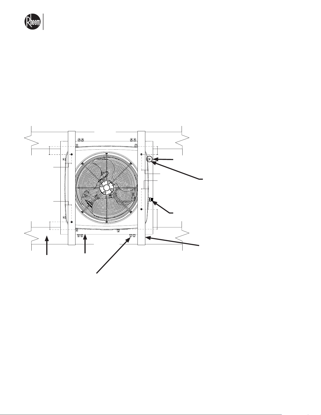
ROOFTOP MOUNT TO ALUMINUM OR STEEL STAND: 35" TALL UNITS
NOTE: Straps are NOT required for ASD wind pressures up to ± 102 psf LATERAL & 81 psf UPLIFT.
(Valid for ASD Wind Pressure up to ± 140 psf Lateral & 111 psf Uplift).
(Aluminum/Steel Host Stand Rails by Others).
FRONT
SIDE
RIGHT
SIDE
LEFT
SIDE
BACK
SIDE
Water
Connections
Bottom steel
pallet
Aluminum/steel stand
rail by others, typ.
Clip
Attachment,
Typ.
UNIT ATTACHMENT DIRECTIVE:
Center unit on steel pallet, typ.
Attach unit to pallet with (7) clips approxi-
mately as shown, (2) per unit corner, ex-
cept for (1) clip at front-left corner, posi-
tion the (1) clip at left side of unit to allow
water connections on front side, typ.
Attach clip to unit wall panel with (4) #10
SAE gr. 2 min. or SS SMS, typ. see detail.
Attach clip to pallet with (1) 3/8" Ø thru-
bolt, typ.
(IF APPLICABLE): TIE-DOWN STRAP
DIRECTIVE:
Provide (2) straps positioned approximate-
ly as shown: (2) straps over opposite sides
and attaching to the undersides of the
stand rails, typ.
Attach each strap end to the underside of
the stand rail with (4) #14 SMS with 1/2"
min. spacing and 3/8" min. edge distance
typ.
To prevent strap slipping, also attach each
strap to the unit top panel with (2) #10
(0.190" Ø) SMS as shown, typ. Screws shall
be positioned per the location/dimensions
marked to avoid damage to the unit.
NOTE: (2) 1" wide straps, each with half the
amount of screws as the 2" wide strap, are
also permitted in place of the 2" strap. All
other strap requirements shall be met.
PALLET ATTACHMENT DIRECTIVE:
Attach pallet to stand rails by others with (8) clips, (4)
per opposite side as shown, positioned towards the
pallet corners as much as is feasible. Provide 1" min.
spacing between clips.
Attach clip to pallet with (5) #10 SMS, typ. see detail.
Attach clip to stand with (1) 1/4" Ø thru-bolt.
4.535" 4.535"
4.535"
4.535"
4.535"
10.035"
4.535"
4.535"
El nuevo grado de confort.
MR
Commercial HEAT PUMP WATER HEATER MONOBLOCK - I&O MANUAL
Page 29
3.6 ANCHOR INSTRUCTIONS FOR HIGH WIND
LOCATION
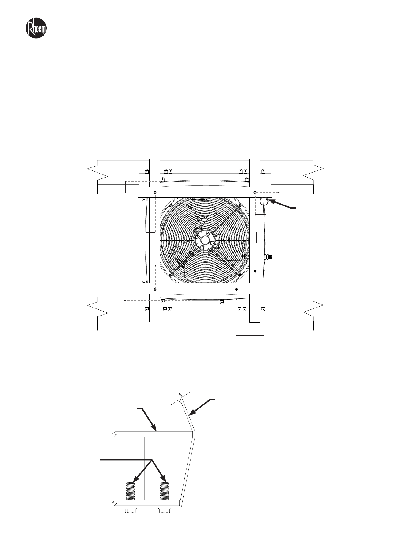
ROOFTOP MOUNT TO ALUMINUM OR STEEL STAND: 51" TALL UNITS
(4-STRAP CONFIGURATION)
(Valid for ASD Wind Pressure up to ± 140 psf Lateral & 111 psf Uplift).
(Aluminum/Steel Host Stand Rails by Others).
TIE-DOWN STRAP ATTACHMENT, TYP.
SCALE: NTS DETAIL VIEW
Tie-down strap
Alum/steel stand rail by
others (or steel metal pallet,
as applicable)
Attach strap end to host
member with (4) #14 SMS,
typ. see roof mount directive
& design notes
DETAILS 8-9 NOTES
The units depicted in the Details on this
page are for illustrative purposes only.
Units may vary in appearance. The tie-
down system may not be depicted in full.
The sample tie-down layouts shown here-
in are for illustrative purposes only. Tie-
down locations may vary per the speci-
fications stated herein. Detail 9 considers
the stand rail member to be an I-beam
shape. Host structure shape may vary.
4.535"
4.535"
4.535"
4.535"
4.535"
10.035"
10.035"
4.535"
4.535"
Clip Attachment, Typ.
El nuevo grado de confort.
MR
Commercial HEAT PUMP WATER HEATER MONOBLOCK - I&O MANUAL
Page 30
3.6 ANCHOR INSTRUCTIONS FOR HIGH WIND
LOCATION
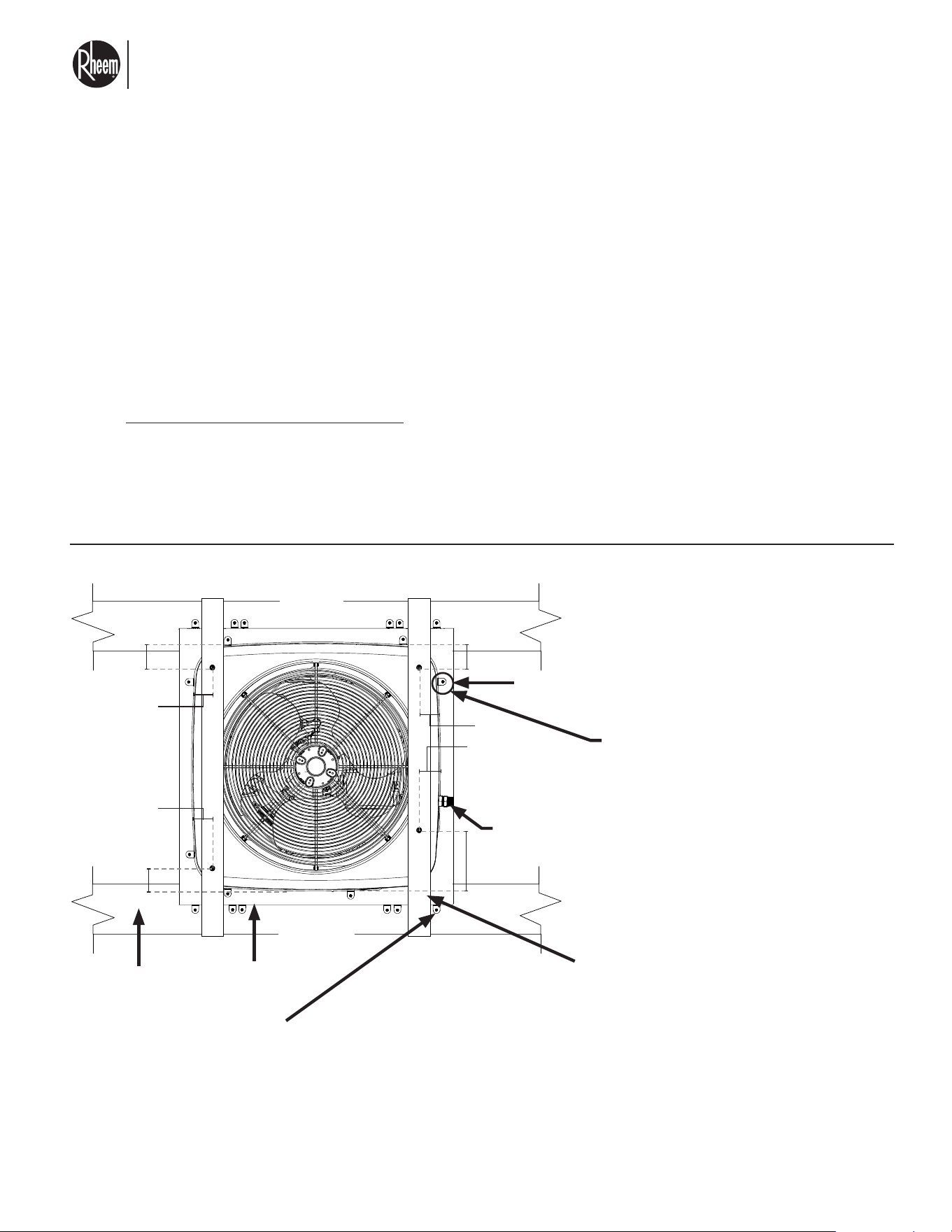
ROOFTOP MOUNT TO ALUMINUM OR STEEL STAND: 51" TALL UNITS
(0- OR 2-STRAP CONFIG.)
(Valid for ASD Wind Pressure up to ± 106 psf Lateral & 84 psf Uplift).
(Aluminum/Steel Host Stand Rails by Others).
NOTE: STRAPS ARE NOT REQUIRED FOR ASD WIND PRESSURES UP TO ± 66 PSF LATERAL & 53 PSF
UPLIFT.
NOTE: PALLET ATTACHMENT DIRECTIVE: FOR ASD WIND PRESSURES UP TO ± 66 PSF LATERAL & 53
PSF UPLIFT, ONLY (8) CLIPS, (4) PER OPPOSITE SIDE ARE REQUIRED INSTEAD OF (12) CLIPS TOTAL.
FOLLOW ALL OTHER SPECIFICATIONS AS NOTED BELOW.
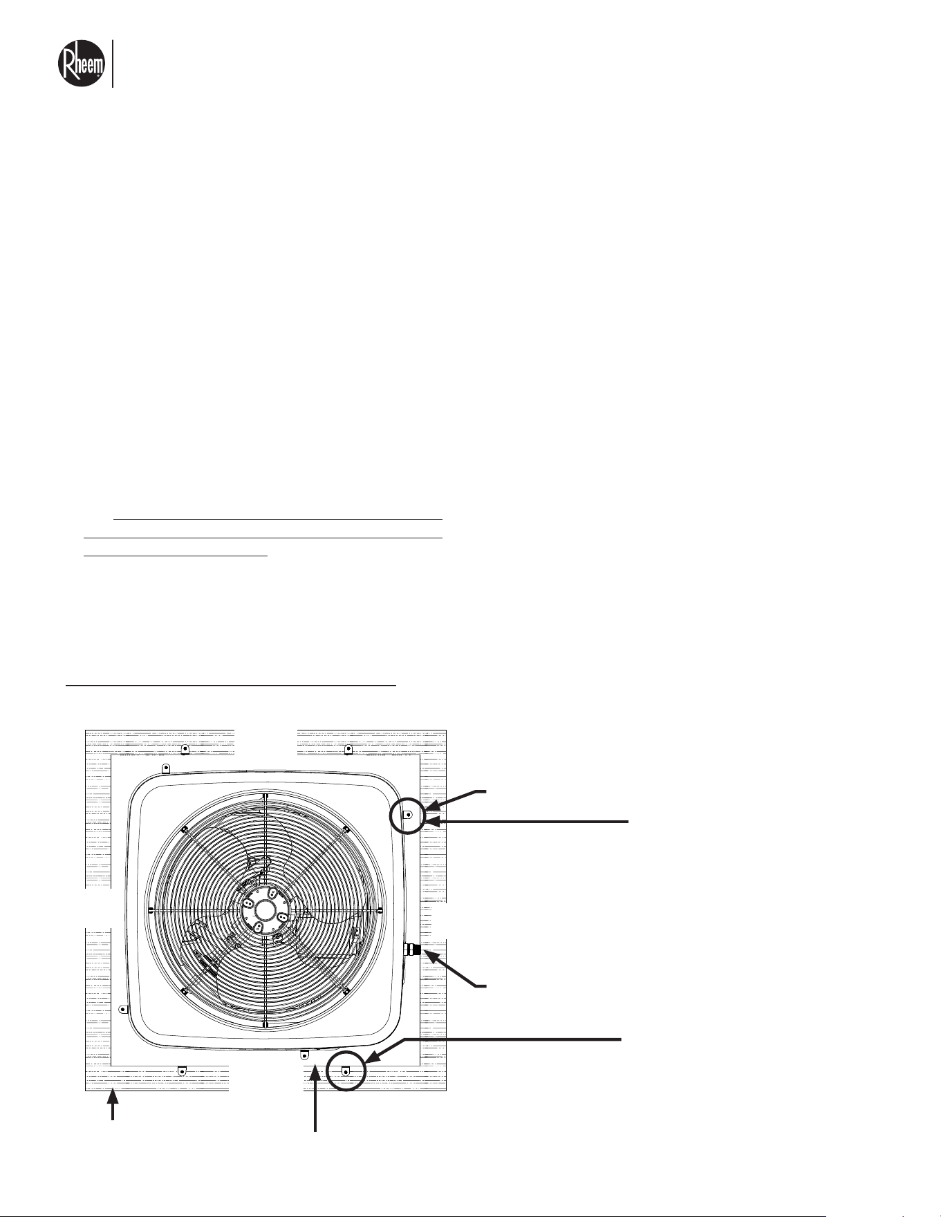
FRONT
SIDE
RIGHT
SIDE
LEFT
SIDE
BACK
SIDE
Water
Connections
Bottom steel
pallet
Aluminum/steel stand
rail by others, typ.
Clip
Attachment,
Typ.
ROOFTOP STAND MOUNT TIE-DOWN DIRECTIVE: 51" TALL UNITS, 0- OR 2-STRAP CONFIGURATION
FOR LOWER WIND PRESSURES
SCALE: NTS TOP VIEW
UNIT ATTACHMENT DIRECTIVE:
Center unit on steel pallet, typ.
Attach unit to pallet with (7) clips approxi-
mately as shown, (2) per unit corner, ex-
cept for (1) clip at front-left corner. Posi-
tion the (1) clip at left side of unit to allow
water connections on front side, typ.
Attach clip to unit wall panel with (4) #10
SAE gr. 2 min. or SS SMS, typ. see detail.
Attach clip to pallet with (1) 3/8" Ø thru-
bolt, typ.
(IF APPLICABLE): TIE DOWN STRAP DIREC-
TIVE:
Provide (2) straps positioned approximately
as shown: (2) straps over opposite sides and
attaching to the undersides of the stand rails,
typ.
Attach each strap end to the underside of the
stand rail with (4) #14 SMS with 1/2" min. spac-
ing and 3/8" min. edge distance, typ.
To prevent strap slipping, also attach each
strap to the unit tip panel with (2) #10 (0.190"
Ø) SMS as shown, typ. screws shall be posi-
tioned per the locations/dimensions marked to
avoid damage to the unit.
NOTE: (2) 1" wide straps, each with half the
amount of screws as the 2" wide strap, are
also permitted in place of the 2" strap. All other
strap requirements shall be met.
PALLET ATTACHMENT DIRECTIVE:
Attach pallet to stand rail by others with (12) clips, (6) per
opposite side as shown, positioned towards the pallet cor-
ners as much as is feasible. Provide 1" min. spacing be-
tween clips.
Attach clip to pallet with (5) #10 SMS, typ. see detail.
Attach clip to stand with (1) 1/4" Ø thru-bolt.
4.535" 4.535"
4.535"
4.535"
4.535"
10.035"
4.535"
4.535"
El nuevo grado de confort.
MR
Commercial HEAT PUMP WATER HEATER MONOBLOCK - I&O MANUAL
Page 31
3.6.1 ANCHOR INSTRUCTIONS FOR SEISMIC
LOCATION
1. All existing supporting host concrete shall have
f'c= 3,000 psi min. compressive strength and shall
be regular-weight, uncracked concrete, design and
integrity by others.
2. "Stand Rail" where used herein refers to equipment
stand rail members, design and integrity by others,
which shall be 0.090" min. thick, 6061-T6 or stronger
aluminum OR 12 GA (0.098") min. thick, ASTM A653
Gr. 33 min. (Fy=33ksi min. Fu=45 ksi min.) galv. steel.
3. "Tie-Down Clip" or "Clip" where used herein:
Each clip shall be 1" min. wide x 0.068" min. thick,
UTS=45 ksi min. (equivalent to ASTM A653 Gr. 33
or stronger) galv. steel, typ. Ensure clip sits flush on
host structure and flush against the unit. Clip to unit
screws shall be positioned as (1) screw per clip slot,
typ. Care must be taken to avoid screw contact with
internal piping and components; exercise with cau-
tion with screw installation.
4. "Sheet Metal Screws" or "SMS" where used herein:
screws shall be SAE Gr. 2 min. or SS self-drilling
screws with washers, typ.
5. "Thru Bolt" where used herein: bolt shall be a UNC
bolt, SAE Gr. 2 min. or SS, with 1" min. OD fender
washers and ID sized for the bolt shank diameter at
the top ad bottom of the connection (under the bolt
head and above the locking nut), and SAE Gr. 2 min.
or SS locking nut at the underside of the connection,
typ. See the thru bolt diameter o the second to last
page of this report.
6. A total of 8 tie down brackets and hardware for in-
stallation are included with the unit. These are in-
tended for secure of unit at 54 psf. If more brack-
ets and hardware are need, these can be obtained
via Rheem replacement parts. Consult your local
dealer. These can be ordered with the part number
10-105931-02.
GROUND MOUNT TO CONCRETE
FRONT
SIDE
RIGHT
SIDE
LEFT
SIDE
BACK
SIDE
GROUND MOUNT TIE-DOWN DIRECTIVE
SCALE: NTS TOP VIEW
3 ksi HOST CONCRETE
BY OTHERS
Bottom Steel Pallet
Water
Connections
Clip Attachment,
Typ.
(Concrete Host by Others)
UNIT ATTACHMENT DIRECTIVE:
Center unit on steel pallet, typ.
Attach unit to pallet with (4) clips,
(1) per unit corner, typ. clip can be
positioned on either side of the unit
corner, typ.
Attach clip to unit wall panel with (4)
#10 SAE gr. 2 min. or SS SMS, typ.
see detail.
Attach clip to pallet with (1) 3/8" Ø,
SAE gr. 5 min. SMS, typ.
PALLET ATTACHMENT DIRECTIVE:
Attach pallet to host concrete by oth-
ers with (4) clips, (1) per pallet corner,
typ. Clip can be positioned on either
side of pallet corner, typ.
Attach clip to pallet with (5) #10 SMS,
typ. see detail.
Attach clip to concrete with (1) 1/4"
Ø ITW tapcon or equivalent with
1-3/4" embedment, 3" min. edge
distance to any concrete edge, and
4-1/4" min. spacing typ.
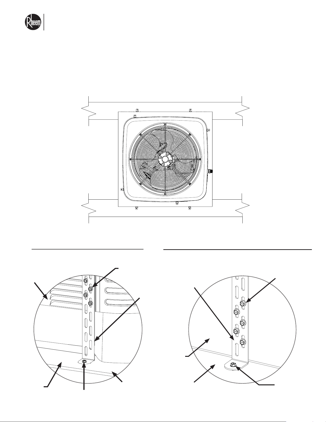
El nuevo grado de confort.
MR
Commercial HEAT PUMP WATER HEATER MONOBLOCK - I&O MANUAL
Page 32
3.6.1 ANCHOR INSTRUCTIONS FOR SEISMIC
LOCATION
ROOF MOUNT TO ALUMINUM OR STEEL STAND
UNIT TO PALLET CLIP ATTACHMENT, TYP.
PALLET TO HOST STRUCTURE CLIP ATTACHMENT, TYP.
SCALE: NTS
SCALE: NTS
ISOMETRIC VIEW
ISOMETRIC VIEW
#10 Screw per
directive, typ.
#10 Screw per
directive, typ.
Steel pallet
Steel pallet
Host structure by others
Plastic unit base (DO NOT
attach screws to base), typ.
Anchor per directive, typ.
Anchor per
directive, typ.
Unit panel typ.
Clip. typ
Clip. typ
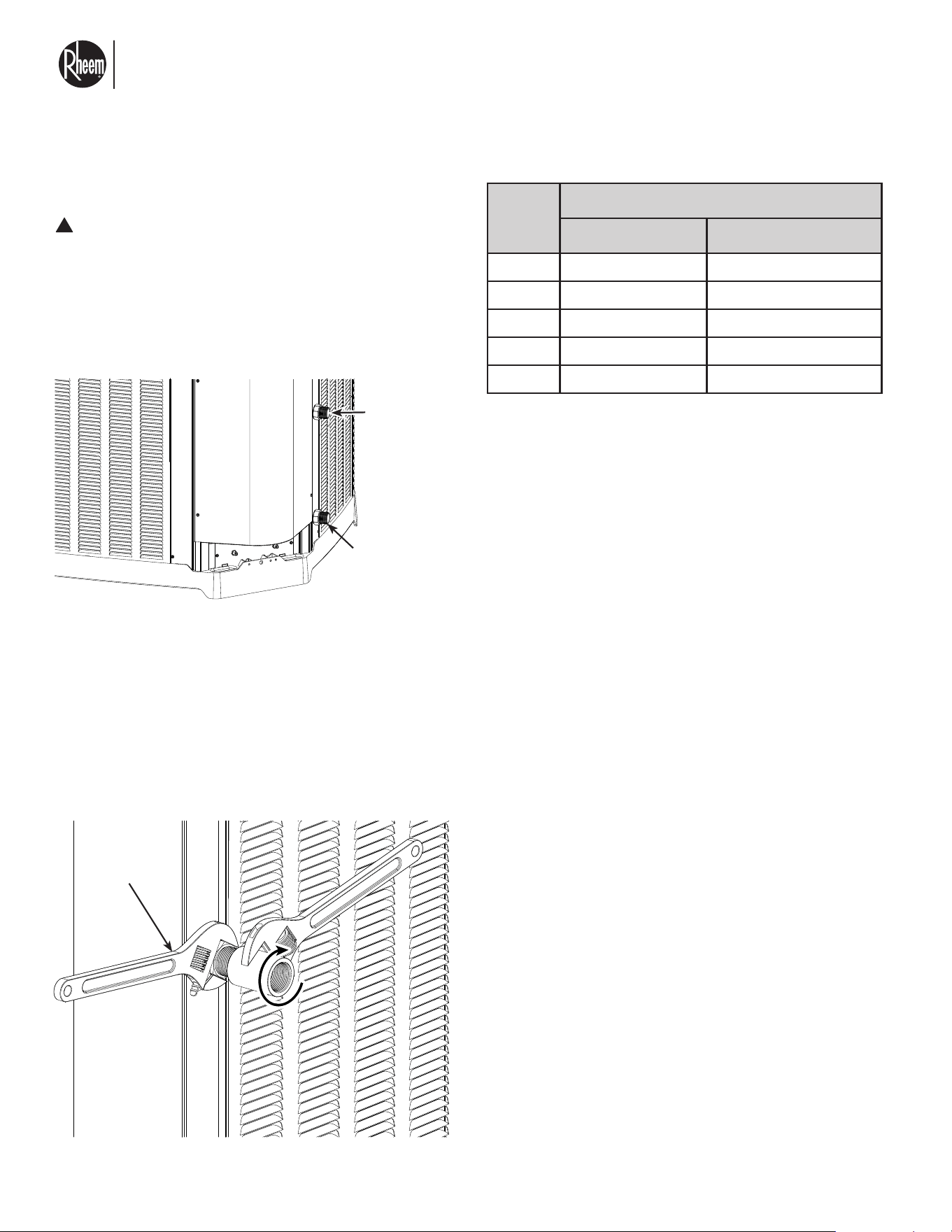
El nuevo grado de confort.
MR
Commercial HEAT PUMP WATER HEATER MONOBLOCK - I&O MANUAL
Page 33
WATER CONNECTIONS
CAUTION:
The heat pump water heater inlet and outlet
connections are NOT interchangeable. They
must be connected as instructed below.
1. Connect the heat pump water heater in the return
water line. See the Plumbing Diagrams in this Man-
ual.
Water Out
Water In
Fig. 5: Water Connections/Drain Plugs
FLOW
(GPM/
LPM)
PRESSURE DROP psi [fthd]
RMHPHDA068 RMHPHDA120
4 0.9 [2.08] 0.25 [0.58]
8 1.26 [2.92] 0.54 [1.25]
12 2.09 [4.83] 1.01 [2.22]
16 3.18 [7.34] 1.59 [3.67]
20 4.48 [10.34] 2.38 [5.5]
NOTE: Swapping water connections will render
unit inoperable.
Water connections to unit are 1" NPT thread male.
Please be aware that the use of a support wrench is
needed when making water connections. This will pre-
vent the piping inside the unit from twisting and potential
damage or water leak from occurring.
!
3.7 WATER PIPING CONNECTIONS
*Support
Wrench
*Support Wrench does not move.
The heat pump water heater is not designed to directly
supply hot water to faucets or showers. The unit must
be paired up with a separate storage tank or tanks, as
shown in the piping diagrams.
STORAGE TANKS
Commercial storage tanks are used to store the hot wa-
ter generated by the heat pump. The tanks must be man-
ifolded to ensure even distribution of the stored energy.
More than one tank can be used. Follow the Manifold
Arrangement diagram in this Manual when manifolding
the tanks.
Refer to the installation instructions supplied with the
storage tanks for specific information relating to the in-
stallation of the storage tanks.
INLET TANK DIFFUSER
It is recommended to install a diffuser at the inlet of the
tank to avoid sudden water inlet temperature increase.
See section 7.0 for part number.
WATER CIRCULATORS
Each heat pump unit must have its own primary water
circulator, to ensure proper flow and temperature in-
crease is achieved. If more than one heat pump is in-
stalled, the manifold must be sized accordingly to allow
the total flow of all the water circulators connected. See
section 3.5 for details on how to connect circulator to
unit.
Water circulator must be capable to supply flow be-
tween 5 and 20 GPM to the unit it is connected to.
See section 7.0 for manufacturer recommended water
circulator.
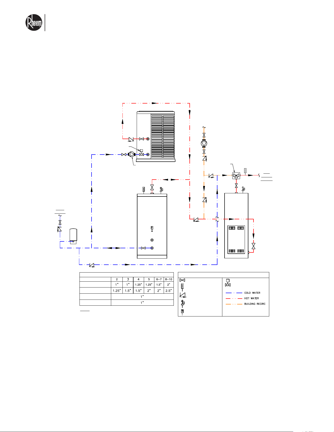
El nuevo grado de confort.
MR
Commercial HEAT PUMP WATER HEATER MONOBLOCK - I&O MANUAL
Page 34
3.7.1 PIPING DIAGRAM FOR SINGLE PASS
WATER HEATING
SHUT-OFF VALVE
CHECK VALVE
TEMPERATURE GAUGE
T & P RELIEF VALVE
TANK-STAT
SINGLE-PASS PIPING DIAGRAM: SPLIT HP, V-STORAGE TANK, & SWING TANK
This drawing is for reference only and shall not be used as an alternative to a professional
engineered project drawing. Any use of this drawing is the responsibility of the party using it.
Refer to local codes or building officials prior to installation
LEGEND
1. This drawing is for illustration purpose only. Please refer to local code requirements for installation of plumbing components
and pipe sizes.
2. Unions are recommended on all water connections.
3. Pipe all relief valves to drain, or as local codes require.
4. Piping to and from heat pumps shall be in a first-in / last-out configuration (reverse/return).
5. Keep heat pump branch lines (inlet & outlet) as short as possible.
6. All single-pass heat pumps require a motorized full port ball valve on the HP inlet water line. The valve should be normally
closed, spring return, and 24VAC. The motorized valve should be wired to the heat pump.
7. All temperature sensors must be installed in thermal wells with thermal conductive paste. Refer to installation manual for
additional details.
8. Building recirc. pump controlled by aqua-stat and/or a timer.
9. Heat pump circulator pumps are variable speed. Refer to heat pump specs document for pump model and additional
information.
10. Expansion tank sized per application.
11. Heat pump condensation drain not shown in drawing. Please refer to Use & Care Manual for additional information. Refer
to local codes for proper removal of condensation.
PIPE DIAMETERS
# OF HEAT PUMPS
MANIFOLD SIZE - 068
MANIFOLD SIZE - 120
BRANCH SIZE - 068
BRANCH SIZE - 120
NOTE: Manifold pipe diameters are based on a velocity of 5 ft/s
STORAGE-1
HP-1
TANK
SENSOR
COLD
WATER
BUILDING
RETURN
HOT
WATER
SUPPLY
RECIRC
PUMP
MIXING VALVE
(Optional)
ELECTRIC
SWING TANK
HP CIRCULATOR
PUMP (Typ.)
MOTORIZED BALL VALVE
Normally Closed (Typ.)
MOTORIZED BALL VALVE
(Normally Closed)
SHUT-OFF VALVE
CHECK VALVE
TEMPERATURE GAUGE
T & P RELIEF VALVE
TANK-STAT
SINGLE-PASS PIPING DIAGRAM: SPLIT HP, V-STORAGE TANK, & SWING TANK
This drawing is for reference only and shall not be used as an alternative to a professional
engineered project drawing. Any use of this drawing is the responsibility of the party using it.
Refer to local codes or building officials prior to installation
LEGEND
1. This drawing is for illustration purpose only. Please refer to local code requirements for installation of plumbing components
and pipe sizes.
2. Unions are recommended on all water connections.
3. Pipe all relief valves to drain, or as local codes require.
4. Piping to and from heat pumps shall be in a first-in / last-out configuration (reverse/return).
5. Keep heat pump branch lines (inlet & outlet) as short as possible.
6. All single-pass heat pumps require a motorized full port ball valve on the HP inlet water line. The valve should be normally
closed, spring return, and 24VAC. The motorized valve should be wired to the heat pump.
7. All temperature sensors must be installed in thermal wells with thermal conductive paste. Refer to installation manual for
additional details.
8. Building recirc. pump controlled by aqua-stat and/or a timer.
9. Heat pump circulator pumps are variable speed. Refer to heat pump specs document for pump model and additional
information.
10. Expansion tank sized per application.
11. Heat pump condensation drain not shown in drawing. Please refer to Use & Care Manual for additional information. Refer
to local codes for proper removal of condensation.
PIPE DIAMETERS
# OF HEAT PUMPS
MANIFOLD SIZE - 068
MANIFOLD SIZE - 120
BRANCH SIZE - 068
BRANCH SIZE - 120
NOTE: Manifold pipe diameters are based on a velocity of 5 ft/s
STORAGE-1
HP-1
TANK
SENSOR
COLD
WATER
BUILDING
RETURN
HOT
WATER
SUPPLY
RECIRC
PUMP
MIXING VALVE
(Optional)
ELECTRIC
SWING TANK
HP CIRCULATOR
PUMP (Typ.)
MOTORIZED BALL VALVE
Normally Closed (Typ.)
MOTORIZED BALL VALVE
(Normally Closed)
SINGLE-PASS PIPING DIAGRAM: SPLIT HP. V-STORAGE TANK, &
SWING TANK
NOTE: We recommend use of metallic pipe, Copper or similar pipe with minimum temperature rating of
175°F.
On high outdoor ambient applications, greater than 95°F ambient, maximum stored water temperature shall
not be greater than 140°F.
Flow from the tank and the unit must be adjusted properly to ensure that more water flows out the tank(s)
than from the unit during a building demand.
For single pass configuration, the use of a shut off valve on the water inlet pipe is recommended. We rec-
ommend 1" NPTF, 24Vac solenoid valve. Consider that for certain applications NSF certification of the valve
may be required.
Single pass only allows use of a variable speed circulator.
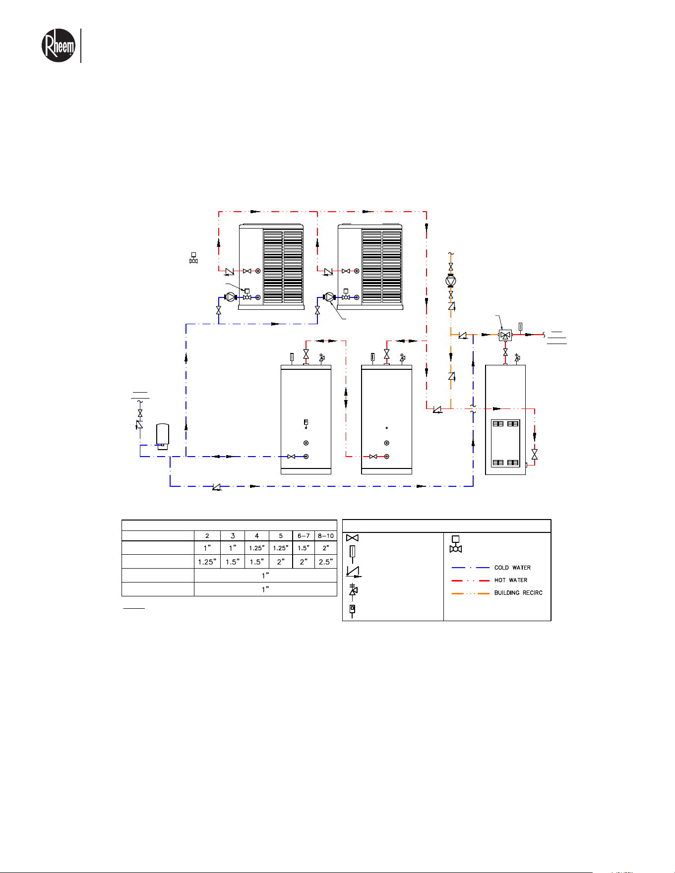
El nuevo grado de confort.
MR
Commercial HEAT PUMP WATER HEATER MONOBLOCK - I&O MANUAL
Page 35
NOTE: We recommend use of metallic pipe, Copper or similar pipe with minimum temperature rating of
175°F.
On high outdoor ambient applications, greater than 95°F ambient, maximum stored water temperature
shall not be greater than 140°F.
Flow from the tank and the unit must be adjusted properly to ensure that more water flows out of the
tank(s) than from the unit during a building demand.
For single pass configuration, the use of a shut off valve on the water inlet pipe is recommended. We
recommend 1" NPTF, 24Vac solenoid valve. Consider that for certain applications NSF certification of
the valve may be required.
Single pass only allows use of a variable speed circulator.
3.7.1 PIPING DIAGRAM FOR SINGLE PASS
WATER HEATING
SHUT-OFF VALVE
CHECK VALVE
TEMPERATURE GAUGE
T & P RELIEF VALVE
TANK-STAT
SINGLE-PASS PIPING DIAGRAM: SPLIT HP, V-STORAGE TANK, & SWING TANK
This drawing is for reference only and shall not be used as an alternative to a professional
engineered project drawing. Any use of this drawing is the responsibility of the party using it.
Refer to local codes or building officials prior to installation
LEGEND
HP-1
STORAGE-1 STORAGE-2
HP-2
TANK
SENSOR
HP CIRCULATOR
PUMP (Typ.)
BUILDING
RETURN
HOT
WATER
SUPPLY
RECIRC
PUMP
MIXING VALVE
(Optional)
ELECTRIC
SWING TANK
COLD
WATER
PIPE DIAMETERS
# OF HEAT PUMPS
MANIFOLD SIZE - 068
MANIFOLD SIZE - 120
BRANCH SIZE - 068
BRANCH SIZE - 120
NOTE: Manifold pipe diameters are based on a velocity of 5 ft/s
MOTORIZED BALL VALVE
Normally Closed (Typ.)
1. This drawing is for illustration purpose only. Please refer to local code requirements for installation of plumbing components
and pipe sizes.
2. Unions are recommended on all water connections.
3. Pipe all relief valves to drain, or as local codes require.
4. Piping to and from heat pumps shall be in a first-in / last-out configuration (reverse/return).
5. Keep heat pump branch lines (inlet & outlet) as short as possible.
6. All single-pass heat pumps require a motorized full port ball valve on the HP inlet water line. The valve should be normally
closed, spring return, and 24VAC. The motorized valve should be wired to the heat pump.
7. All temperature sensors must be installed in thermal wells with thermal conductive paste. Refer to installation manual for
additional details.
8. Building recirc. pump controlled by aqua-stat and/or a timer.
9. Heat pump circulator pumps are variable speed. Refer to heat pump specs document for pump model and additional
information.
10. Expansion tank sized per application.
11. Heat pump condensation drain not shown in drawing. Please refer to Use & Care Manual for additional information. Refer
to local codes for proper removal of condensation.
MOTORIZED BALL VALVE
(Normally Closed)
SINGLE-PASS PIPING DIAGRAM: SPLIT HP. V-STORAGE TANK, &
SWING TANK
SHUT-OFF VALVE
CHECK VALVE
TEMPERATURE GAUGE
T & P RELIEF VALVE
TANK-STAT
SINGLE-PASS PIPING DIAGRAM: SPLIT HP, V-STORAGE TANK, & SWING TANK
This drawing is for reference only and shall not be used as an alternative to a professional
engineered project drawing. Any use of this drawing is the responsibility of the party using it.
Refer to local codes or building officials prior to installation
LEGEND
HP-1
STORAGE-1
STORAGE-2
HP-2
TANK
SENSOR
HP CIRCULATOR
PUMP (Typ.)
BUILDING
RETURN
HOT
WATER
SUPPLY
RECIRC
PUMP
MIXING VALVE
(Optional)
ELECTRIC
SWING TANK
COLD
WATER
PIPE DIAMETERS
# OF HEAT PUMPS
MANIFOLD SIZE - 068
MANIFOLD SIZE - 120
BRANCH SIZE - 068
BRANCH SIZE - 120
NOTE: Manifold pipe diameters are based on a velocity of 5 ft/s
MOTORIZED BALL VALVE
Normally Closed (Typ.)
1. This drawing is for illustration purpose only. Please refer to local code requirements for installation of plumbing components
and pipe sizes.
2. Unions are recommended on all water connections.
3. Pipe all relief valves to drain, or as local codes require.
4. Piping to and from heat pumps shall be in a first-in / last-out configuration (reverse/return).
5. Keep heat pump branch lines (inlet & outlet) as short as possible.
6. All single-pass heat pumps require a motorized full port ball valve on the HP inlet water line. The valve should be normally
closed, spring return, and 24VAC. The motorized valve should be wired to the heat pump.
7. All temperature sensors must be installed in thermal wells with thermal conductive paste. Refer to installation manual for
additional details.
8. Building recirc. pump controlled by aqua-stat and/or a timer.
9. Heat pump circulator pumps are variable speed. Refer to heat pump specs document for pump model and additional
information.
10. Expansion tank sized per application.
11. Heat pump condensation drain not shown in drawing. Please refer to Use & Care Manual for additional information. Refer
to local codes for proper removal of condensation.
MOTORIZED BALL VALVE
(Normally Closed)
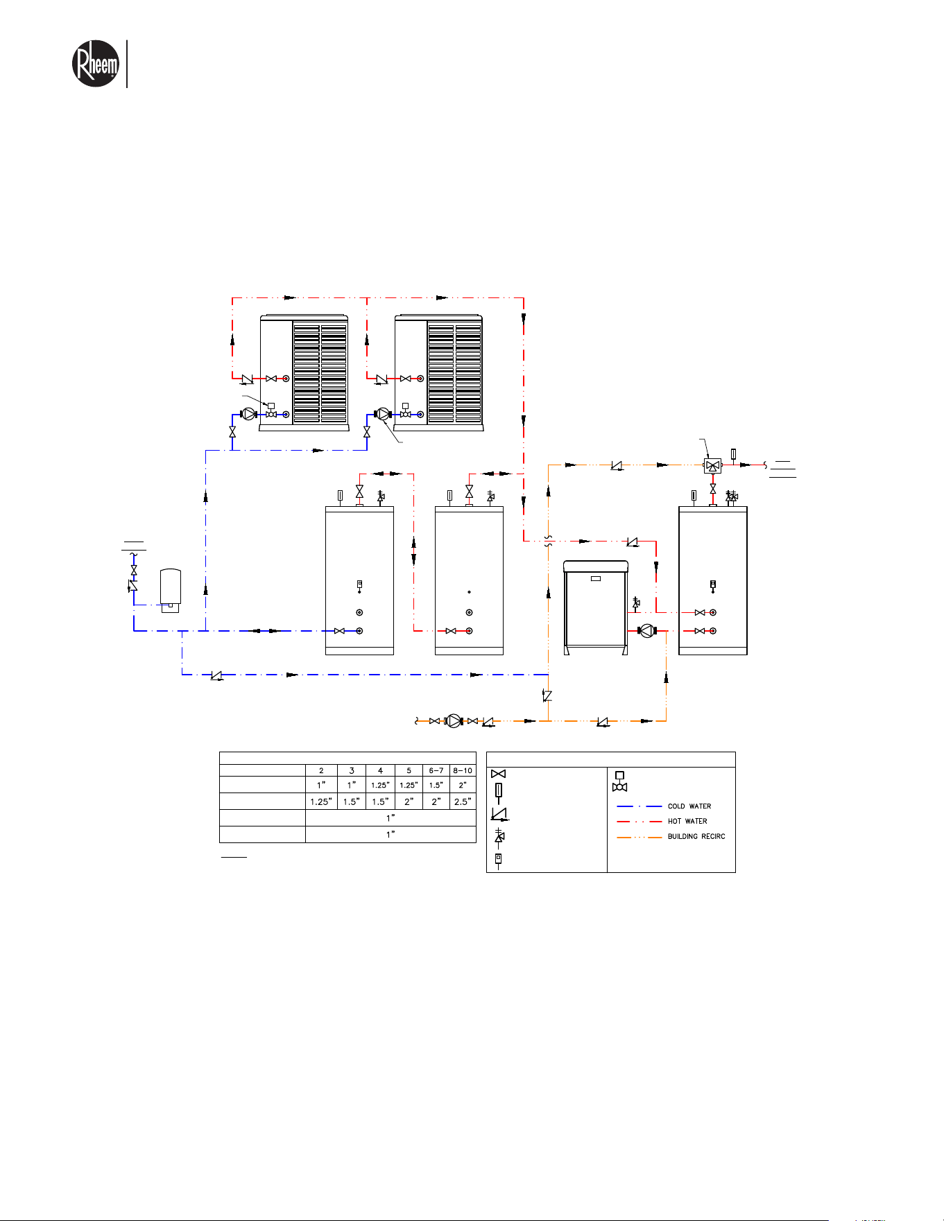
El nuevo grado de confort.
MR
Commercial HEAT PUMP WATER HEATER MONOBLOCK - I&O MANUAL
Page 36
SHUT-OFF VALVE
CHECK VALVE
TEMPERATURE GAUGE
T & P RELIEF VALVE
TANK-STAT
PIPING DIAGRAM: SPLIT HP, V-STORAGE TANK, SWING TANK & GAS BACKUP
This drawing is for reference only and shall not be used as an alternative to a professional
engineered project drawing. Any use of this drawing is the responsibility of the party using it.
Refer to local codes or building officials prior to installation
LEGEND
BUILDING
RETURN
COLD
WATER
HP-1
STORAGE-1
HOT
WATER
SUPPLY
STORAGE-2
HP-2
TANK
SENSOR
RECIRC
PUMP
HP CIRCULATOR
PUMP (Typ.)
MIXING VALVE
(Optional)
SWING TANK
GAS HEATER
PIPE DIAMETERS
# OF HEAT PUMPS
MANIFOLD SIZE - 068
MANIFOLD SIZE - 120
BRANCH SIZE - 068
BRANCH SIZE - 120
NOTE: Manifold pipe diameters are based on a velocity of 5 ft/s
MOTORIZED BALL VALVE
Normally Closed (Typ.)
1. This drawing is for illustration purpose only. Please refer to local code requirements for installation of plumbing components
and pipe sizes.
2. Unions are recommended on all water connections.
3. Pipe all relief valves to drain, or as local codes require.
4. Piping to and from heat pumps shall be in a first-in / last-out configuration (reverse/return).
5. Keep heat pump branch lines (inlet & outlet) as short as possible.
6. All single-pass heat pumps require a motorized full port ball valve on the HP inlet water line. The valve should be normally
closed, spring return, and 24VAC. The motorized valve should be wired to the heat pump.
7. All temperature sensors must be installed in thermal wells with thermal conductive paste. Refer to installation manual for
additional details.
8. Building recirc. pump controlled by aqua-stat and/or a timer.
9. Heat pump circulator pumps are variable speed. Refer to heat pump specs document for pump model and additional
information.
10. Expansion tank sized per application.
11. Heat pump condensation drain not shown in drawing. Please refer to Use & Care Manual for additional information. Refer
to local codes for proper removal of condensation.
MOTORIZED BALL VALVE
(Normally Closed)
PIPING DIAGRAM: SPLIT HP. V-STORAGE TANK, SWING & GAS
BACKUP
3.7.1 PIPING DIAGRAM FOR SINGLE PASS
WATER HEATING
SHUT-OFF VALVE
CHECK VALVE
TEMPERATURE GAUGE
T & P RELIEF VALVE
TANK-STAT
PIPING DIAGRAM: SPLIT HP, V-STORAGE TANK, SWING TANK & GAS BACKUP
This drawing is for reference only and shall not be used as an alternative to a professional
engineered project drawing. Any use of this drawing is the responsibility of the party using it.
Refer to local codes or building officials prior to installation
LEGEND
BUILDING
RETURN
COLD
WATER
HP-1
STORAGE-1
HOT
WATER
SUPPLY
STORAGE-2
HP-2
TANK
SENSOR
RECIRC
PUMP
HP CIRCULATOR
PUMP (Typ.)
MIXING VALVE
(Optional)
SWING TANK
GAS HEATER
PIPE DIAMETERS
# OF HEAT PUMPS
MANIFOLD SIZE - 068
MANIFOLD SIZE - 120
BRANCH SIZE - 068
BRANCH SIZE - 120
NOTE: Manifold pipe diameters are based on a velocity of 5 ft/s
MOTORIZED BALL VALVE
Normally Closed (Typ.)
1. This drawing is for illustration purpose only. Please refer to local code requirements for installation of plumbing components
and pipe sizes.
2. Unions are recommended on all water connections.
3. Pipe all relief valves to drain, or as local codes require.
4. Piping to and from heat pumps shall be in a first-in / last-out configuration (reverse/return).
5. Keep heat pump branch lines (inlet & outlet) as short as possible.
6. All single-pass heat pumps require a motorized full port ball valve on the HP inlet water line. The valve should be normally
closed, spring return, and 24VAC. The motorized valve should be wired to the heat pump.
7. All temperature sensors must be installed in thermal wells with thermal conductive paste. Refer to installation manual for
additional details.
8. Building recirc. pump controlled by aqua-stat and/or a timer.
9. Heat pump circulator pumps are variable speed. Refer to heat pump specs document for pump model and additional
information.
10. Expansion tank sized per application.
11. Heat pump condensation drain not shown in drawing. Please refer to Use & Care Manual for additional information. Refer
to local codes for proper removal of condensation.
MOTORIZED BALL VALVE
(Normally Closed)
NOTE: We recommend use of metallic pipe, Copper or similar pipe with minimum temperature rating of
175°F.
On high outdoor ambient applications, greater than 95°F ambient, maximum stored water temperature
shall not be greater than 140°F.
Flow from the tank and the unit must be adjusted properly to ensure that more water flows out of the
tank(s) than from the unit during a building demand.
For single pass configuration, the use of a shut off valve on the water inlet pipe is recommended. We
recommend 1" NPTF, 24Vac solenoid valve. Consider that for certain applications NSF certification of
the valve may be required.
Single pass only allows use of a variable speed circulator.
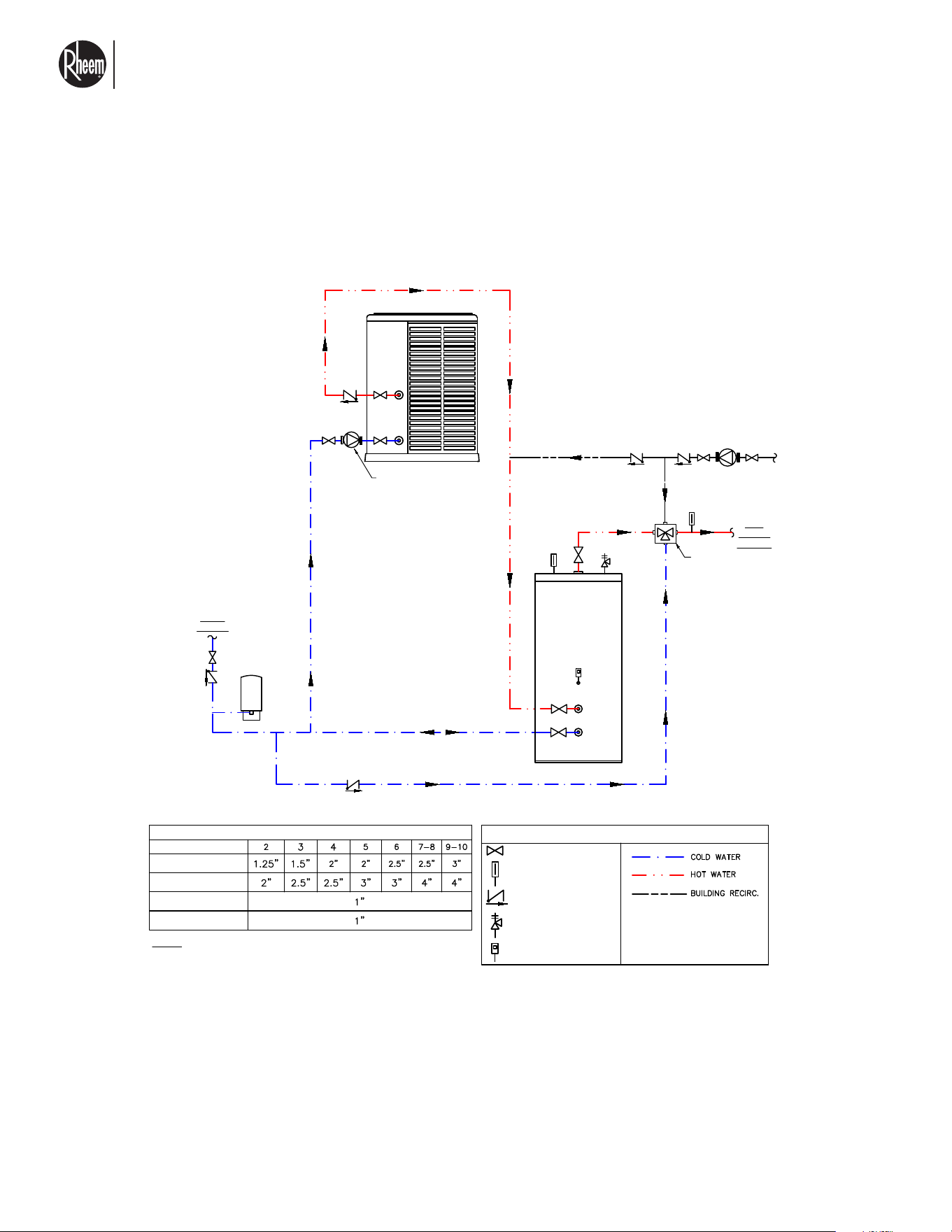
El nuevo grado de confort.
MR
Commercial HEAT PUMP WATER HEATER MONOBLOCK - I&O MANUAL
Page 37
3.7.2 PIPING DIAGRAM FOR MULTIPASS WATER
HEATING
SHUT-OFF VALVE
CHECK VALVE
TEMPERATURE GAUGE
T & P RELIEF VALVE
TANK-STAT
MULTI-PASS PIPING DIAGRAM: SPLIT HP & V-STORAGE TANK
This drawing is for reference only and shall not be used as an alternative to a professional
engineered project drawing. Any use of this drawing is the responsibility of the party using it.
Refer to local codes or building officials prior to installation
LEGEND
COLD
WATER
STORAGE-1
HP-1
TANK
SENSOR
HOT
WATER
SUPPLY
MIXING VALVE
(Optional)
HP CIRCULATOR
PUMP (Typ.)
1. This drawing is for illustration purpose only. Please refer to local code requirements for installation of plumbing components
and pipe sizes.
2. Unions are recommended on all water connections.
3. Pipe all relief valves to drain, or as local codes require.
4. Piping to and from heat pumps and tanks shall be in a first-in / last-out configuration (reverse/return).
5. Keep heat pump branch lines (inlet & outlet) as short as possible.
6. All temperature sensors must be installed in thermal wells with thermal conductive paste. Refer to installation manual for
additional details.
7. Building recirc. pump controlled by aqua-stat and/or a timer.
8. Heat pump supports constant speed or variable speed circulator pumps in multi-pass. Refer to heat pump specs document
for circulator model and additional information.
9. Expansion tank sized per application.
10. Heat pump condensation drain not shown in drawing. Please refer to Use & Care Manual for additional information. Refer
to local codes for proper removal of condensation.
PIPE DIAMETERS
# OF HEAT PUMPS
MANIFOLD SIZE - 068
MANIFOLD SIZE - 120
BRANCH SIZE - 068
BRANCH SIZE - 120
NOTE: Manifold pipe diameters are based on a velocity of 5 ft/s
BUILDING RECIRC
(Optional)
RECIRC PUMP
MULTI-PASS PIPING DIAGRAM: SPLIT HP & V-STORAGE TANK
SHUT-OFF VALVE
CHECK VALVE
TEMPERATURE GAUGE
T & P RELIEF VALVE
TANK-STAT
MULTI-PASS PIPING DIAGRAM: SPLIT HP & V-STORAGE TANK
This drawing is for reference only and shall not be used as an alternative to a professional
engineered project drawing. Any use of this drawing is the responsibility of the party using it.
Refer to local codes or building officials prior to installation
LEGEND
COLD
WATER
STORAGE-1
HP-1
TANK
SENSOR
HOT
WATER
SUPPLY
MIXING VALVE
(Optional)
HP CIRCULATOR
PUMP (Typ.)
1. This drawing is for illustration purpose only. Please refer to local code requirements for installation of plumbing components
and pipe sizes.
2. Unions are recommended on all water connections.
3. Pipe all relief valves to drain, or as local codes require.
4. Piping to and from heat pumps and tanks shall be in a first-in / last-out configuration (reverse/return).
5. Keep heat pump branch lines (inlet & outlet) as short as possible.
6. All temperature sensors must be installed in thermal wells with thermal conductive paste. Refer to installation manual for
additional details.
7. Building recirc. pump controlled by aqua-stat and/or a timer.
8. Heat pump supports constant speed or variable speed circulator pumps in multi-pass. Refer to heat pump specs document
for circulator model and additional information.
9. Expansion tank sized per application.
10. Heat pump condensation drain not shown in drawing. Please refer to Use & Care Manual for additional information. Refer
to local codes for proper removal of condensation.
PIPE DIAMETERS
# OF HEAT PUMPS
MANIFOLD SIZE - 068
MANIFOLD SIZE - 120
BRANCH SIZE - 068
BRANCH SIZE - 120
NOTE: Manifold pipe diameters are based on a velocity of 5 ft/s
BUILDING RECIRC
(Optional)
RECIRC PUMP
NOTE: We recommend use of metallic pipe, Copper or similar pipe with minimum temperature rating of
175°F.
On high outdoor ambient applications, greater than 95°F ambient, maximum stored water temperature
shall not be greater than 140°F.
Flow from the tank and the unit must be adjusted properly to ensure that more water flows out of the
tank(s) than from the unit during a building demand.
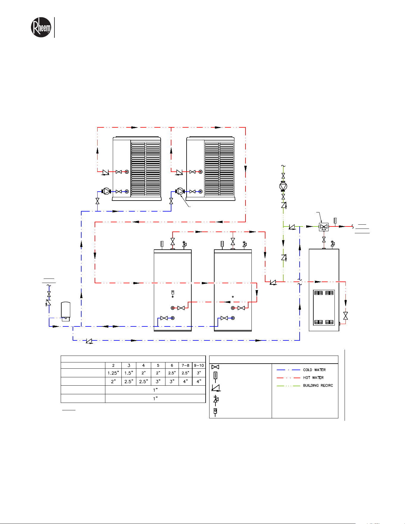
El nuevo grado de confort.
MR
Commercial HEAT PUMP WATER HEATER MONOBLOCK - I&O MANUAL
Page 38
3.7.2 PIPING DIAGRAM FOR MULTIPASS WATER
HEATING
SHUT-OFF VALVE
CHECK VALVE
TEMPERATURE GAUGE
T & P RELIEF VALVE
TANK-STAT
MULTI-PASS PIPING DIAGRAM: SPLIT HP, V-STORAGE TANK & SWING TANK
This drawing is for reference only and shall not be used as an alternative to a professional
engineered project drawing. Any use of this drawing is the responsibility of the party using it.
Refer to local codes or building officials prior to installation
LEGEND
COLD
WATER
HP-1
STORAGE-1 STORAGE-2
HP-2
TANK
SENSOR
HP CIRCULATOR
PUMP (Typ.)
BUILDING
RETURN
HOT
WATER
SUPPLY
RECIRC
PUMP
MIXING VALVE
(Optional)
ELECTRIC
SWING TANK
(Optional)
PIPE DIAMETERS
# OF HEAT PUMPS
MANIFOLD SIZE - 068
MANIFOLD SIZE - 120
BRANCH SIZE - 068
BRANCH SIZE - 120
NOTE: Manifold pipe diameters are based on a velocity of 5 ft/s
1. This drawing is for illustration purpose only. Please refer to local code requirements for installation of plumbing components
and pipe sizes.
2. Unions are recommended on all water connections.
3. Pipe all relief valves to drain, or as local codes require.
4. Piping to and from heat pumps and tanks shall be in a first-in / last-out configuration (reverse/return).
5. Keep heat pump branch lines (inlet & outlet) as short as possible.
6. All temperature sensors must be installed in thermal wells with thermal conductive paste. Refer to installation manual for
additional details.
7. Building recirc. pump controlled by aqua-stat and/or a timer.
8. Heat pump supports constant speed or variable speed circulator pumps in multi-pass configuration. Refer to heat pump
specs document for circulator model and additional information.
9. Expansion tank sized per application.
10. Heat pump condensation drain not shown in drawing. Please refer to Use & Care Manual for additional information. Refer
to local codes for proper removal of condensation.
MULTI-PASS PIPING DIAGRAM: SPLIT HP. V-STORAGE TANK &
SWING TANK
SHUT-OFF VALVE
CHECK VALVE
TEMPERATURE GAUGE
T & P RELIEF VALVE
TANK-STAT
MULTI-PASS PIPING DIAGRAM: SPLIT HP, V-STORAGE TANK & SWING TANK
This drawing is for reference only and shall not be used as an alternative to a professional
engineered project drawing. Any use of this drawing is the responsibility of the party using it.
Refer to local codes or building officials prior to installation
LEGEND
COLD
WATER
HP-1
STORAGE-1 STORAGE-2
HP-2
TANK
SENSOR
HP CIRCULATOR
PUMP (Typ.)
BUILDING
RETURN
HOT
WATER
SUPPLY
RECIRC
PUMP
MIXING VALVE
(Optional)
ELECTRIC
SWING TANK
(Optional)
PIPE DIAMETERS
# OF HEAT PUMPS
MANIFOLD SIZE - 068
MANIFOLD SIZE - 120
BRANCH SIZE - 068
BRANCH SIZE - 120
NOTE: Manifold pipe diameters are based on a velocity of 5 ft/s
1. This drawing is for illustration purpose only. Please refer to local code requirements for installation of plumbing components
and pipe sizes.
2. Unions are recommended on all water connections.
3. Pipe all relief valves to drain, or as local codes require.
4. Piping to and from heat pumps and tanks shall be in a first-in / last-out configuration (reverse/return).
5. Keep heat pump branch lines (inlet & outlet) as short as possible.
6. All temperature sensors must be installed in thermal wells with thermal conductive paste. Refer to installation manual for
additional details.
7. Building recirc. pump controlled by aqua-stat and/or a timer.
8. Heat pump supports constant speed or variable speed circulator pumps in multi-pass configuration. Refer to heat pump
specs document for circulator model and additional information.
9. Expansion tank sized per application.
10. Heat pump condensation drain not shown in drawing. Please refer to Use & Care Manual for additional information. Refer
to local codes for proper removal of condensation.
NOTE: We recommend use of metalic pipe, Copper or similar pipe with minimum temperature rating of
175°F
On high outdoor ambient applications, greater than 95°F ambient, maximum stored water temperature
shall not be greater than 140°F.
Flow from the tank and the unit must be adjusted properly to ensure that more water flows out of the
tank(s) than from the unit during a building demand.
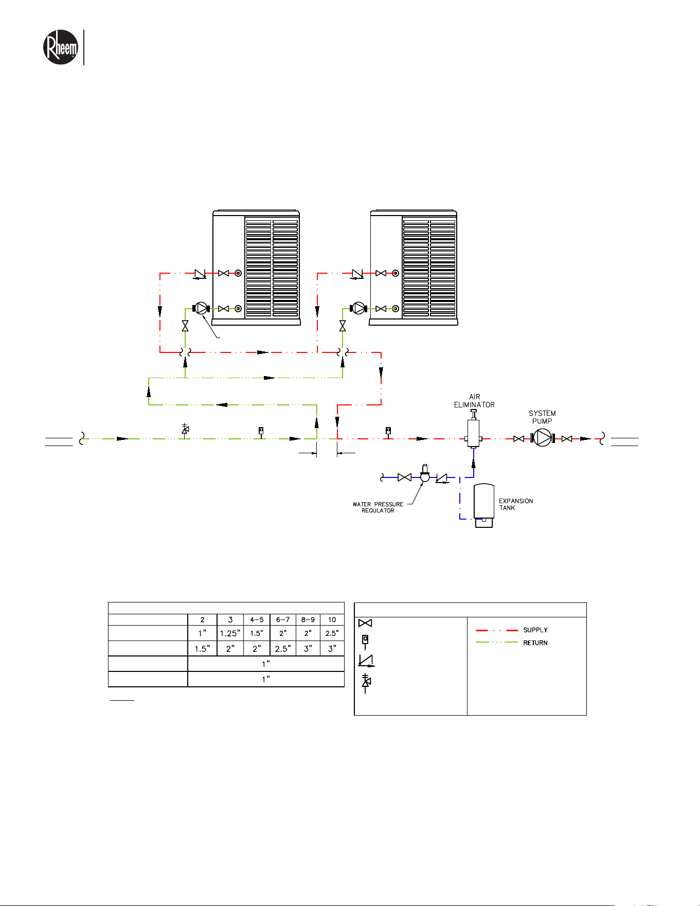
El nuevo grado de confort.
MR
Commercial HEAT PUMP WATER HEATER MONOBLOCK - I&O MANUAL
Page 39
3.7.3 PIPING DIAGRAM FOR SPACE HEATING
HYDRONIC PIPING DIAGRAM: SPLIT HP PRIMARY / SECONDARY
SHUT-OFF VALVE
CHECK VALVE
RELIEF VALVE
TEMPERATURE SENSOR
HYDRONIC PIPING DIAGRAM: SPLIT HP PRIMARY / SECONDARY
This drawing is for reference only and shall not be used as an alternative to a professional
engineered project drawing. Any use of this drawing is the responsibility of the party using it.
Refer to local codes or building officials prior to installation
LEGEND
SYSTEM
RETURN
HP-1
HP CIRCULATOR
PUMP (Typ.)
SYSTEM
SUPPLY
COLD
WATER FILL
4 x Pipe Dia.
or
12" Max
HP-2
1. This drawing is for illustration purpose only. Please refer to local code requirements for installation of plumbing components
and pipe sizes.
2. Unions are recommended on all water connections.
3. Pipe all relief valves to drain, or as local codes require.
4. Piping to and from heat pumps shall be in a first-in / last-out configuration (reverse/return).
5. Keep heat pump branch lines (inlet & outlet) as short as possible.
6. All temperature sensors must be installed in thermal wells with thermal conductive paste. Refer to installation manual for
additional details.
7. Heat pump supports constant speed or variable speed circulator pumps in multi-pass configuration. Refer to heat pump
specs document for circulator model and additional information.
8. Expansion tank sized per application.
9. Heat pump condensation drain not shown in drawing. Please refer to Use & Care Manual for additional information. Refer
to local codes for proper removal of condensation.
PIPE DIAMETERS
# OF HEAT PUMPS
MANIFOLD SIZE - 068
MANIFOLD SIZE - 120
BRANCH SIZE - 068
BRANCH SIZE - 120
NOTE: Manifold pipe diameters are based on a velocity of 5 ft/s
SHUT-OFF VALVE
CHECK VALVE
RELIEF VALVE
TEMPERATURE SENSOR
HYDRONIC PIPING DIAGRAM: SPLIT HP PRIMARY / SECONDARY
This drawing is for reference only and shall not be used as an alternative to a professional
engineered project drawing. Any use of this drawing is the responsibility of the party using it.
Refer to local codes or building officials prior to installation
LEGEND
SYSTEM
RETURN
HP-1
HP CIRCULATOR
PUMP (Typ.)
SYSTEM
SUPPLY
COLD
WATER FILL
4 x Pipe Dia.
or
12" Max
HP-2
1. This drawing is for illustration purpose only. Please refer to local code requirements for installation of plumbing components
and pipe sizes.
2. Unions are recommended on all water connections.
3. Pipe all relief valves to drain, or as local codes require.
4. Piping to and from heat pumps shall be in a first-in / last-out configuration (reverse/return).
5. Keep heat pump branch lines (inlet & outlet) as short as possible.
6. All temperature sensors must be installed in thermal wells with thermal conductive paste. Refer to installation manual for
additional details.
7. Heat pump supports constant speed or variable speed circulator pumps in multi-pass configuration. Refer to heat pump
specs document for circulator model and additional information.
8. Expansion tank sized per application.
9. Heat pump condensation drain not shown in drawing. Please refer to Use & Care Manual for additional information. Refer
to local codes for proper removal of condensation.
PIPE DIAMETERS
# OF HEAT PUMPS
MANIFOLD SIZE - 068
MANIFOLD SIZE - 120
BRANCH SIZE - 068
BRANCH SIZE - 120
NOTE: Manifold pipe diameters are based on a velocity of 5 ft/s
NOTE: We recommend use of metallic pipe, Copper or similar pipe with minimum temperature rating of
175°F.
On high outdoor ambient applications, greater than 95°F ambient, maximum stored water temperature
shall not be greater than 140°F.
El nuevo grado de confort.
MR
Commercial HEAT PUMP WATER HEATER MONOBLOCK - I&O MANUAL
Page 40
3.8 INDOOR INSTALLATION LOCATION
CONSIDERATIONS
INDOOR INSTALLATION OF THE WATER HEATER
• Indoor installation relies on flammable refrigerant
sensor for safe operation. Do not tamper, disable, or
otherwise impair the sensor. Doing so will void war-
ranty and can cause unsafe operation. Unit must be
powered up at all times.
• Keep flammable liquids and gases away from unit. If
gas water heaters are also installed in the indoor vi-
cinity, these must be at least 6ft away from the unit,
to prevent flame or pilot extinguish due to air cur-
rents.
• Consider that enclosed areas will greatly increase
the noise perception of the units. Install the units
in areas as far away as feasible from places where
sound might be an issue.
DUCTING ADVISORY
Ducting this unit will significantly increase its static pres-
sure, which may result in elevated noise levels, reduced
performance, and potential motor stress or damage.
For optimal performance and reliability it is recommend-
ed that the unit be installed in a non-ducted configu-
ration or that a dedicated fan-assisted system be de-
signed where ducting is unavoidable.
This equipment is designed to operate under low static
pressure conditions, with a recommended maximum
discharge static pressure of 0.2 in. w.c.
IMPORTANT CONSIDERATIONS
• This unit is not designed to be ducted, the fan is not
capable of overcoming significant external static
pressure
• Any addition of ductwork, louvers, dampers or exter-
nal components will increase resistance to airflow.
Exceeding the recommended discharge static
pressure may result in loss of system capac-
ity and efficiency, increased system freeze and
defrost potentially leading to long term reliability
concerns.
These units use A2L refrigerant, minimum room volume
for install is as follows.
Non ducted:
RMHPHDA068: 4300 ft3 (121.7 m3)
RMHPHDA120: 7400 ft3 (209.5 m3)
Consult with your local Rheem applications engineer
for louver sizing based on your room size.
Louver size listed on the next page is only for purposes
of proper refrigerant venting in case of leak.
VENTILATION & LOUVER CONSIDERATIONS
Components such as louvers, dampers and exhaust
systems can significantly contribute to static pressure.
Careful sizing of such components is required. Note
that typical louver assemblies may exceed or be very
close to max allowable static pressure limit.
The design and implementation of any ducted configu-
ration, including but not limited to
* Static pressure calculations
* Airflow verifications
* Fan selection (if needed)
Remain the responsibility of the installing contractor
and/or project design engineer.
MODEL AIRFLOW
RMHPHDA068 6000 SCFM
RMHPHDA120 6000 SCFM
Disclaimer: this guide is provided as manufacturer recommendation for installation requirement. Final system design
and compliance with local codes and standard remain the responsibility of the project design team.
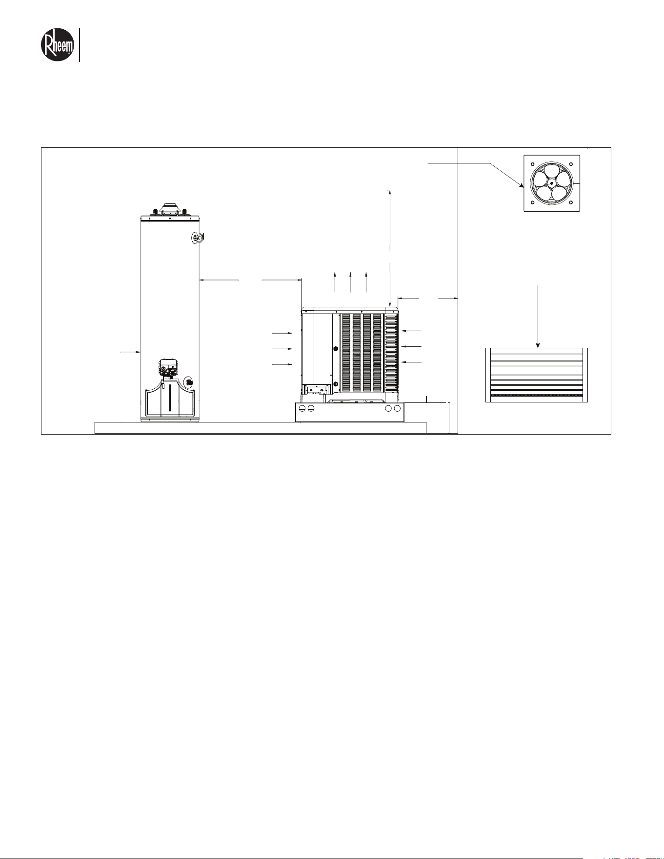
El nuevo grado de confort.
MR
Commercial HEAT PUMP WATER HEATER MONOBLOCK - I&O MANUAL
Page 41
GAS OR
ELECTRIC
WATER
HEATER
6 FT
(1.80m)
MIN
AIR
FLOW
IN
AIR
FLOW
IN
AIR FLOW OUT
60” (1.52m) MIN
Indoor extractor fan (recommended)
must see table for extraction CFM and
static pressure.
Fresh air intakes. Louvers
or venting Minimum
ventilation area to be
calculated per UL60335-2-40
Annex GG section 8.2
24”
(0.6m)
2 FT
(0.6m)
MIN
Louver size is for single unit, if multiple units are installed indoors, then the louver size and air extraction must match
the amount of units.
3.8 INDOOR INSTALLATION LOCATION
CONSIDERATIONS

El nuevo grado de confort.
MR
Commercial HEAT PUMP WATER HEATER MONOBLOCK - I&O MANUAL
Page 42
1. Is the heat pump water heater properly located
and level?
2. Is air free to travel around all four sides on the
heat pump water heater?
3. Is the wiring correct and according to the unit wir-
ing diagram?
4. Are wiring connections tight? (Including those in
unit and compressor electrical box.)
5. Is the unit properly grounded?
6. Is unit properly fused?
7. Condensate drain line properly sized, run, tapped
and pitched?
8. Are water connections properly installed, tight
and leak tested?
9. Is the water circulator properly installed, water
flow is the right direction and is sized accord-
ingly?
10. Does the fan turn free without rubbing?
11. Is the fan tight in the fan shaft?
12. Are all covers and access panels in place to pre-
vent air loss?
13. Is water flowing through the water heater?
14. For indirect tank heating, is the glycol to water
ratio the appropriate. Consult piping diagram for
estimated mix.
15. The actual REFRIGERANT CHARGE is in accor-
dance with the room size within which the refrig-
erant containing parts are installed.
16. Ventilation machinery and outlets are operating
adequately and are not obstructed.
17. If an indirect refrigerating circuit is being used,
the secondary circuit shall be checked for the
presence of refrigerant.
18. Markings on the equipment continues to be vis-
ible and legible. Markings and signs that are illeg-
ible shall be corrected.
19. Refrigerating pipe or components are installed in
a position where they are unlikely to be exposed
to any substance which may corrode refrigerant
containing components, unless the components
are constructed of materials which are inherently
resistant to being corroded or are suitably pro-
tected against being so corroded.
4.1 HEAT PUMP WATER HEATER PRE-START
CHECK LIST
4.0 START-UP
TO TURN ON WATER HEATER
* Make sure power is applied to the unit.
* Make sure that water circulator is powered up and
all water valves feeding the water loop are in the
right position.
* Make sure water tanks are full and all air has been
purged from pipes.
* Select your desired water outlet set point. After five
minutes of initial power up, your unit should start
running. Note that the circulation pump between
your tank and heaters can start a little earlier than
the unit.
TO TURN OFF THE WATER HEATER
* Disable the heater from the unit controller.
* Shut off the power to the unit.
* Shut off the flow of water to the unit.
* Disconnect power to the circulation pump.

El nuevo grado de confort.
MR
Commercial HEAT PUMP WATER HEATER MONOBLOCK - I&O MANUAL
Page 43
4.2 SYSTEM START UP AND OPERATIONAL
CHECK UP
TEMPERATURE CONTROL
The unit begins heating when a command is received
from the controller (Sky-35) Heating continues until the
water temperature reaches the set point, at this time
the heater operation will be terminated.
ADDITIONAL FEATURES
CIRCULATOR CONTROL
The control system supports:
* Single-speed circulator: 0.75A @ 24Vac max
* Variable-speed circulator: 10mA @ 0–12VDC
AMBIENT (OUTSIDE) LOCKOUT
* High Ambient Lockout: > 115°F
* Low Ambient Lockout: < –13°F
The unit will not operate outside this range. If ambi-
ent conditions exceed limits during operation, heating
stops and an alarm is triggered. Operation resumes
automatically once ambient conditions return to range.
HEAT MODE
* Heating starts after a five-minute compressor start
delay and confirmation of water flow. This five min-
ute delay is a safety feature and is active upon
power up or at the end of heat cycle.
* The fan runs with the compressor and may stop
earlier during shutdown or remain on for a few sec-
onds after cycle ends. This is normal behavior.
* The circulator continues to run for two minutes af-
ter heating ends.
FAULT HISTORY
* Stores the last 25 errors in a FIFO buffer.
* Errors are time stamped and viewable via the user
interface or service tool.
COMPRESSOR DISCHARGE TEMPERATURE
Upon detection of high compressor discharge temper-
ature, the unit will act to reduce compressor speed in
order to cool down.
DEFROST OPERATION
* Initiates when evaporator temperature is lower than
35°F for 34 minutes.
* Compressor speed is reduced, then increased to
optimize defrost.
* Heating output is reduced during defrost; auxiliary
heat is recommended if needed
FREEZE PROTECTION
* Activates circulator and/or low-speed heating to
prevent pipe freezing.
* Circulator runs for at least 120 seconds.
* Fan may operate during this cycle—use caution
when servicing.
HIGH WATER TEMPERATURE LIMIT
The control software of the heat pump will continuously
monitor water outlet temp and will act to reduce com-
pressor power in order to avoid water temperatures
greater than 165°F.
It is recommended to review piping for proper water
flow through the unit as well as the water inlet tem-
perature.

El nuevo grado de confort.
MR
Commercial HEAT PUMP WATER HEATER MONOBLOCK - I&O MANUAL
Page 44
4.2 SYSTEM START UP AND OPERATIONAL
CHECK UP
HIGH PRESSURE TRANSDUCER
High protection pressure will be triggered when liquid
line pressure is high. Upon triggering this condition, an
alarm will be declared and compressor speed will be
gradually reduced.
Fan will be kept on during this time to help reduce the
high pressure on the system.
LOW PRESSURE TRANSDUCER
Low pressure alarm will be set when suction pressure
is below a safety threshold for two minutes of con-
tinuously running the unit. When this fault is declared,
compressor speed will be modulated to keep pressure
above 20 psi.
WATER FLOW SWITCH
Unit is equipped with a water flow switch. The water
flow switch shall provide a signal to the heat pump to
allow heating operation. Water flow switch will prove
flow through the unit and allow for safe heating. The
water flow switch is installed internally on the water
piping and is a critical component for a safe system
operation.
FLAMMABLE REFRIGERANT SENSOR
The heat pump water heater comes equipped with a
flammable refrigerant sensor. This sensor is calibrated
to detect leaks of refrigerant and shut off the unit. This
sensor is mandated for safe and reliable installations
and should not be removed or tampered with in any
way.
• Detects refrigerant leaks and shuts down the unit.
• Activates alarm and keeps fan running.
• Must remain installed and powered for safety.
• Sensor lifespan: 15 years. Sensor must be tested
and/or replaced according to the manufacturer's
recommended time.
CRANKCASE HEATER
The heat pump water heater is equipped with a crank-
case heater. This heater is installed around the com-
pressor and it is critical to prevent refrigerant from
condensing inside the compressor during off periods.
Crankcase heater operation will be carried out when
the compressor is shut off and active only when am-
bient temperature around the unit is lower than 40°F.
Heater will turn once every minute to keep compressor
warm. The heater is a 90-watt resistive strip installed
around the compressor.
SEASONAL START-UP OR
ANNUAL CHECK
NOTE: During initial start up or during ex-
tended off periods, heater might need to run for
extended and continuous periods. This heater is
design to operate for extended time.
1. Remove leaves, pine needles, etc., from the
evaporator coil. Clean the coil by gently applying a
mild solution of household liquid soap and water.
2. Remove the side louvered panels by removing the
single screw at the top of each louvered panel. Lift
and pull the bottom out. The panel will easily come
away from the cabinet giving access to the coil for
cleaning.
3. Gently rinse the coil with water; DO NOT use high
pressure.
4. Re-install the side louvered panels and secure
each with the single screw at the top center of each
panel.
5. Set the valves to ensure proper water flow through
the unit.
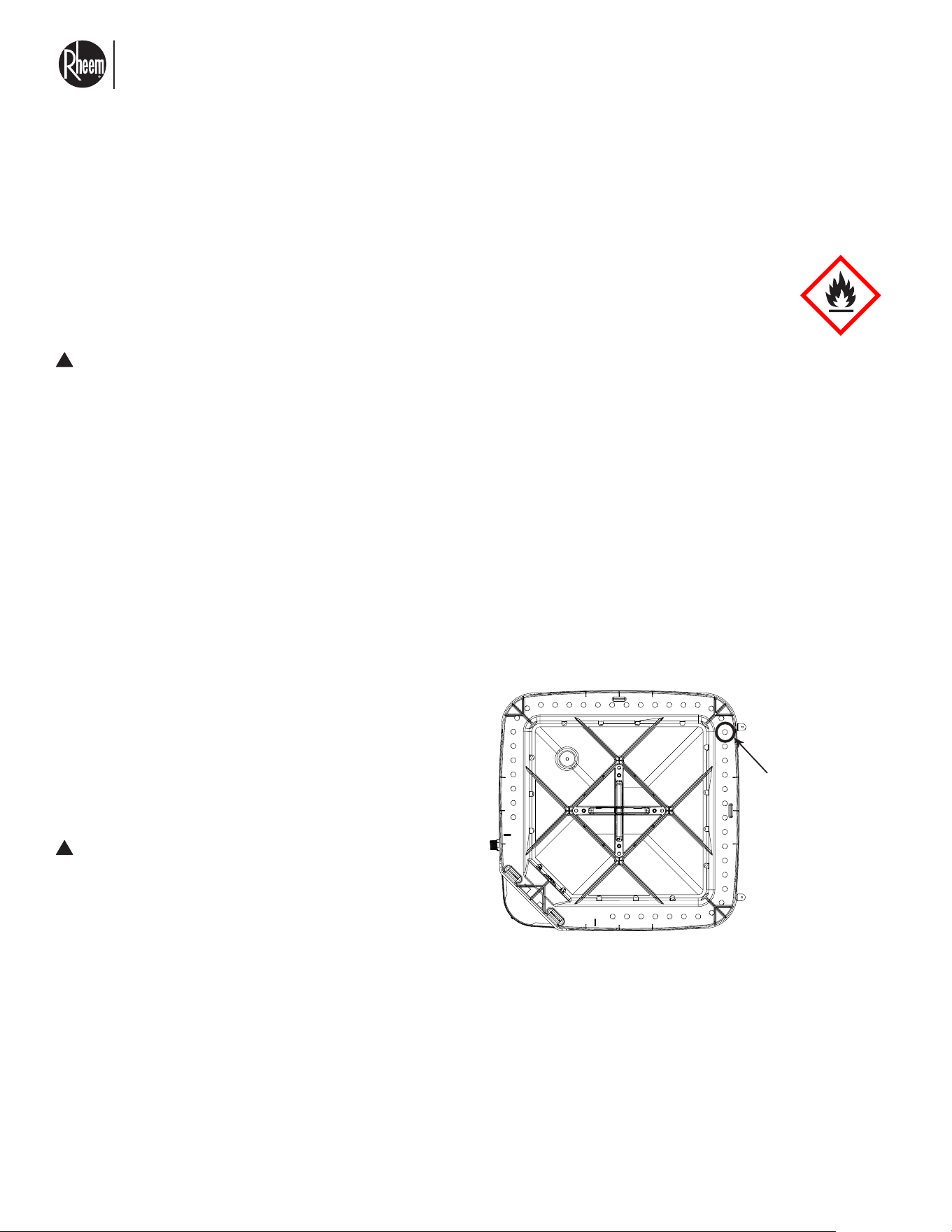
El nuevo grado de confort.
MR
Commercial HEAT PUMP WATER HEATER MONOBLOCK - I&O MANUAL
Page 45
5.1 MAINTENANCE
OUTDOOR COIL CLEANING
The outdoor fan draws air across the coil dur-
ing operation which results in contaminants col-
lecting on and between the aluminum fins. These
contaminants restrict the air-flow through the coil
resulting in reduced capacity and efficiency and in-
creases the temperature of the components that
can reduce their life. Therefore, it is recommended
that the outdoor coil be cleaned at least annually
by a qualified service technician using a non-corrosive
coil cleaner and low pressure water hose sprayer. Care
must be taken not to damage or flatten out the fins by
spraying the fins from an angle. Washing from the top
of the coil down from the inside out is the most effec-
tive method of cleaning the coil. The exterior louver
panels and unit top are easily removable to facilitate
the coil cleaning task.
WARNING: Disconnect electrical power to
the unit before removing the top panel or any
electrical panel as the fan motor could start at
any time and live electrical connections will be
exposed.
CABINET CLEANING AND CARE
Annual cleaning of the exterior cabinet is rec-
ommended using a mild detergent, water, and
cloth/sponge to remove dust, mold, and potentially
corrosive contaminants that have collected on the
cabinet. DO NOT apply wax to the cabinet since the
painted surface is textured which will result in a
white wax build-up. Make sure drain holes are free of
blockages to allow proper drainage.
!
!
CAUTION: R-454B is classified as safety group A2L per ASHRAE Standard 34. Verify that service
equipment and instruments are approved for use with group A2L refrigerants, and in particular with
R-454B. Failure to exercise care may result in equipment damage or personal injury.
* Before servicing disconnect power to the unit, wait at least five minutes before opening electrical
panel. This allows any capacitors to discharge and prevent electrical shocks.
Drain
Holes
Condensate Drain Hole Locations.
5.0 SERVICE AND MAINTENANCE
At least once a year, schedule service checks must be made to verify the safety systems in this unit are working as
intended. For continuing high performance and to minimize possible equipment failures, it is essential that periodic
maintenance be performed. This section provides general guidelines on items to consider for maintenance and fre-
quency.
El nuevo grado de confort.
MR
Commercial HEAT PUMP WATER HEATER MONOBLOCK - I&O MANUAL
Page 46
5.2 REFRIGERANT CONNECTIONS SERVICE
AND CHECK
5.1.1 WORKING PERSONNEL
REMOVAL AND EVACUATION
Although the heat pump water heater is a sealed system,
vacuuming and recharging may be required in some cas-
es. Follow these steps carefully:
1. Refrigerant Recovery
Recover all refrigerant into R-454B-approved recovery
cylinders only.
2. System Purging
Purge the system using oxygen-free nitrogen.
Do not use compressed air or oxygen, as this can create a
fire or explosion hazard with R-454B.
3. Purging Procedure
• Break the vacuum with oxygen-free nitrogen.
• Pressurize the system to working pressure.
• Vent to atmosphere.
• Pull a vacuum.
• Repeat this cycle until all refrigerant is removed.
• For the final purge, vent the nitrogen to atmospher-
ic pressure before beginning service.
4. Ignition Source Precautions
• DO NOT use open flames, smoking materials, or
any ignition sources near the unit during service.
• Ensure the area is free of flammable materials be-
fore starting work.
• Post “No Smoking” signs clearly around the work
area.
5. Removal and Evacuation
This procedure is required during removal and evacu-
ation and must be followed:
a. When breaking into the refrigeration circuit for any
reason, use a refrigeration vacuum circulator ca-
pable of evacuation in the 500 micro range.
b. Connect the vacuum circulator to the service mani-
fold assembly with a pressure gauge that will read
30 inches vacuum.
c. Connect the service manifold to the suction line
Schrader valve port.
d. Ensure there is no power to the unit.
e. With an accurate scale, ½ oz., set the refrigerant
recovery cylinder in the upright position.
f. Connect the recovery cylinder to the unit using the
service valves.
g. Evacuate refrigerant from the unit until the vacuum
circulator reads a minimum of 500 microns.
h. Purge the refrigeration circuit with inert gas until
there is no refrigerant within the system.
i. Using the inert gas in the system, pressurize the
unit accordingly and check the refrigerant joints for
leaks.
• If leaks are detected, make repairs to the joints
and check for leaks again.
• If no leaks are detected, continue to the next step.
j. Evacuate the circuit again.
k. Once all inert gas is removed, pull a vacuum on the
unit to check for any leaks in the system. If a leak
is suspected, all naked flames shall be removed/
extinguished.
l. If leaks are present, spray a soapy substance over
the refrigeration circuit. Bubbles will help locate the
leak. Avoid using detergent that contain chlorine.
Chlorine may react with refrigerant and corrode
copper.
m. Patch the leak and pull a vacuum again. Continu-
ously flush or purge with inert gas when using flame
to open circuit.
DANGER: Risk of Fire or Explosion. Flam-
mable Refrigerant Used. To Be Repaired Only
By Trained Service Personnel. Do Not Puncture
Refrigerant Tubing.
Every installation, maintenance, service, and repair
working procedure must be conducted by qualified
personnel who have been trained in operating and ser-
vicing units that employ flammable refrigerants such as
R-454B.
Examples of working procedures include but are not
limited to:
• Breaking into the refrigeration circuit
• Opening sealed components
• Opening ventilated enclosures
!
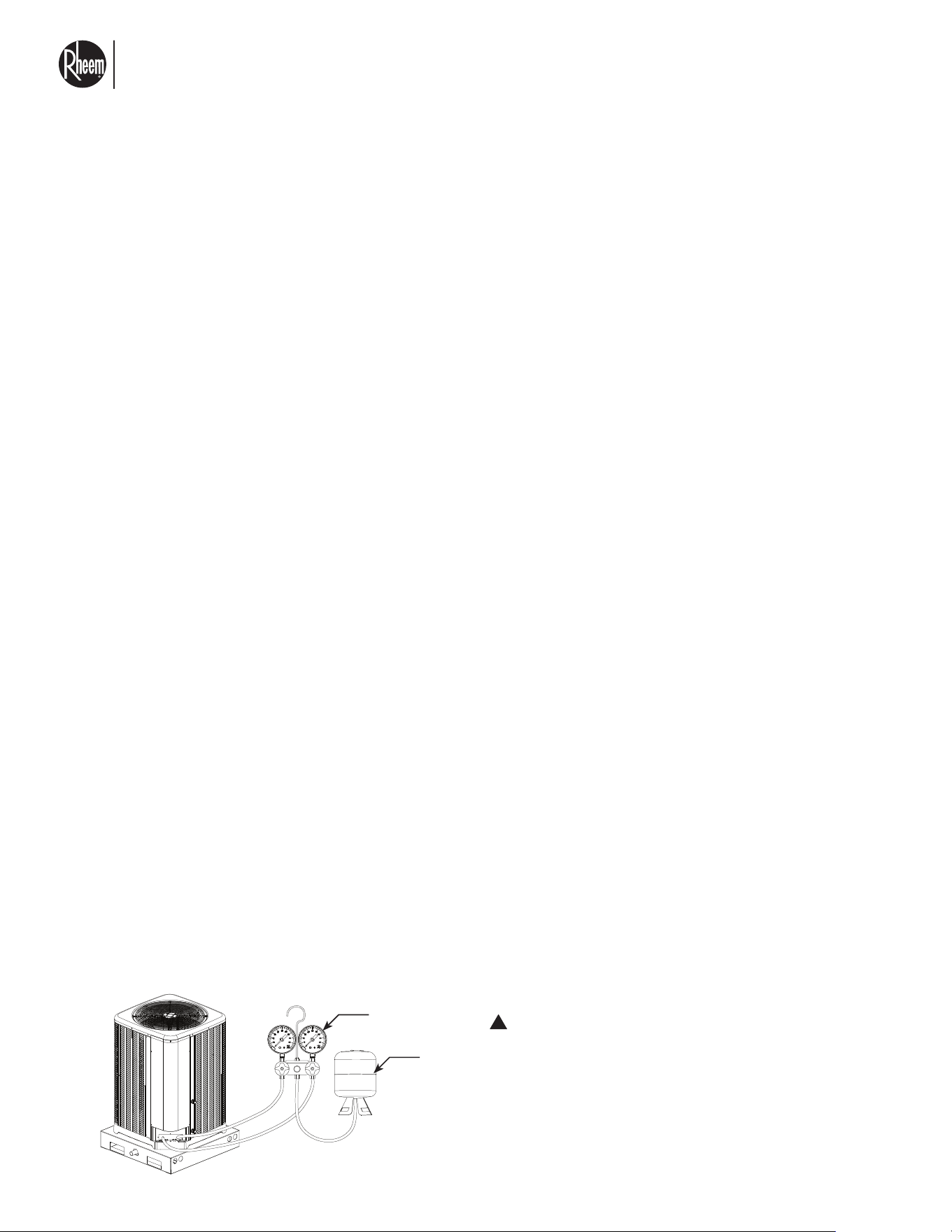
El nuevo grado de confort.
MR
Commercial HEAT PUMP WATER HEATER MONOBLOCK - I&O MANUAL
Page 47
5.2 REFRIGERANT CONNECTIONS SERVICE
AND CHECK
CHARGING PROCEDURE
Prior to recharging the system, complete a leak check
and purge the system with inert gas as detailed in Re-
moval and Evacuation of Refrigerant. The charging
procedure steps are as follows:
1. Ensure that the unit is properly grounded before
beginning charging.
2. Install the R-454B refrigerant cylinder to the unit
service valve.
3. Before tightening, purge the cylinder and service
valve hose to ensure that the contamination of dif-
ferent refrigerants does not occur when using the
charging equipment.
• Hoses of lines shall be as short as possible to
minimize the amount of refrigerant contained in
them.
4. Place tank following the manufacturer recom-
mended orientation. Make sure tank is not moving
or shifting position during the charging procedure.
5. Check unit rating label or consult this manual to get
refrigerant charge weight.
6. Replace service port caps and valve stern caps.
These caps must be replaced to prevent leaks.
After charging is complete, a leak test must be done.
Before leaving the site, an additional leak test must
also be done at the end of installation.
Only use recovery machines, gauges, and hoses rated
for A2L refrigerants (e.g., R-32, R-454B). Improper tools
may cause ignition or equipment damage.
n. If leaks are still detected, repeat steps 11 to 14.
o. If no leaks are present, charge the system as di-
rected in the next section.
p. Remove the vacuum circulator from suction, dis-
charge, and liquid shut-off.
q. Electronic leak detectors may be used to detect re-
frigerant leaks but, in the case of FLAMMABLE RE-
FRIGERANTS, the sensitivity may not be adequate,
or may need re-calibration. (Detection equipment
shall be calibrated in a refrigerant-free area.) Ensure
that the detector is not a potential source of igni-
tion and is suitable for the refrigerant used. Leak
detection equipment shall be set at a percentage of
the LFL of the refrigerant and shall be calibrated to
the refrigerant employed, and the appropriate per-
centage of gas (25% maximum) is confirmed.
r. If a leakage of refrigerant is found which requires
brazing, all of the refrigerant shall be recovered
from the system, or isolated (by means of shut-off
valves) in a part of the system remote from the leak.
Removal of refrigerant shall be done in accordance
with local codes and Clause DD.9 from UL60335-
2-40.
REMOVAL AND EVACUATION
Gauges
Tank
WARNING: In the event of a refrigerant leak,
ventilate the area immediately. Do not operate
electrical devices or switches that may cause
sparks.
!
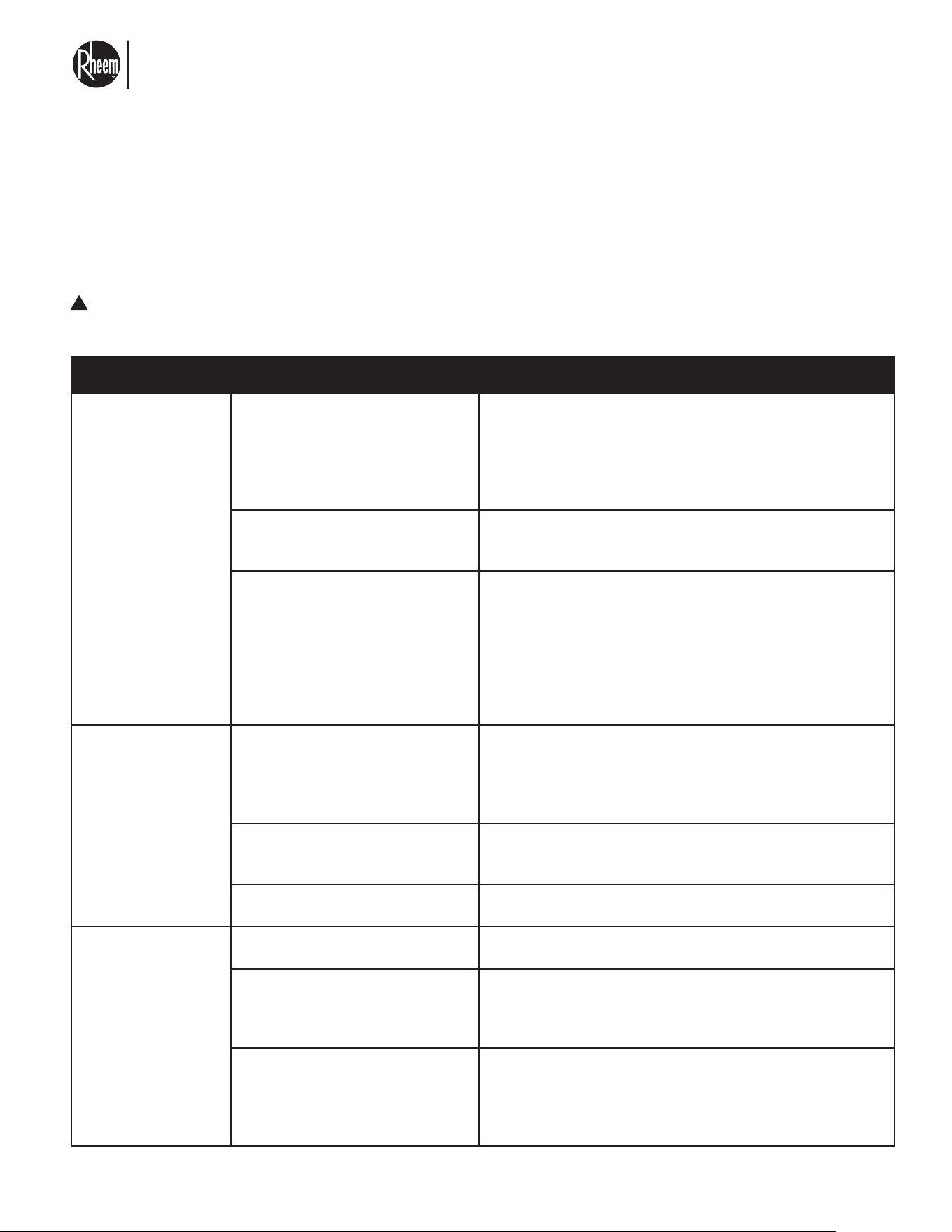
El nuevo grado de confort.
MR
Commercial HEAT PUMP WATER HEATER MONOBLOCK - I&O MANUAL
Page 48
6.1 WHAT DO TO IN CASE OF FAILURES
6.0 DIAGNOSTICS
GENERAL TROUBLESHOOTING
WARNING: Disconnect all power to unit before servicing. Failure to shut off power can cause
electrical shock resulting in personal injury or death.
!
SYMPTOM POSSIBLE CAUSE REMEDY
Unit will not run
No voltage on unit
1. Confirm correct voltage, phase and frequency are
connected to the water heater. If using a step-down or
up transformer, confirm the right taps are being used.
2. Confirm that breaker or fuses are not tripped.
3. Check system phases, confirm all phases are supplying
voltage.
No heat demand is being
received
1. Review wiring between heat pump and Sky-35.
2. Confirm that both Sky-35 system and units are grounded
to the same physical earth.
No water flow is present through
unit
1. Confirm that water flow is present through unit and
that unit water circulator is powered up and properly
connected. See section 3.5 for circulator control wiring.
2. Confirm water flow is at least 3.3 GPM and is flowing in
the right direction.
3. Confirm that flow switch is making when flow is present.
Review wiring diagram, flow switch wires can be
measured for continuity.
Unit circulator not
running
Circulator not wired properly
1. Confirm circulator is connected to proper voltage.
2. Confirm proper activation signal is connected from the
heat pump unit. Heat pump supports single speed and
variable speed circulator. See section 3.5 for circulator
wiring.
Water valves closed
1. Confirm that all water valves, strainers, check valves and
other piping to and from the heat pump water heater are
open and in the right flow direction.
No heat demand is being
received
Review wiring between heat pump and Sky-35.
Outdoor fan runs,
compressor does
not
Bad inverter driver
1. Review error codes on Sky-35 display.
2. Error on inverter driver, contact tech support.
Bad compressor or wiring
1. Review compressor wiring per the wiring diagram.
2. Disconnect wires from VFD and measure continuity
between wires and to ground. Any wire that has
continuity with ground means a bad compressor.
Flammable refrigerant sensor
activated
If a leak is present in the system, the flammable refrigerant
sensor will be activated. During this time, heating operation
is disabled and fan will run continuously until sensor is
reset. Please note this is a safety feature and should not be
disabled.
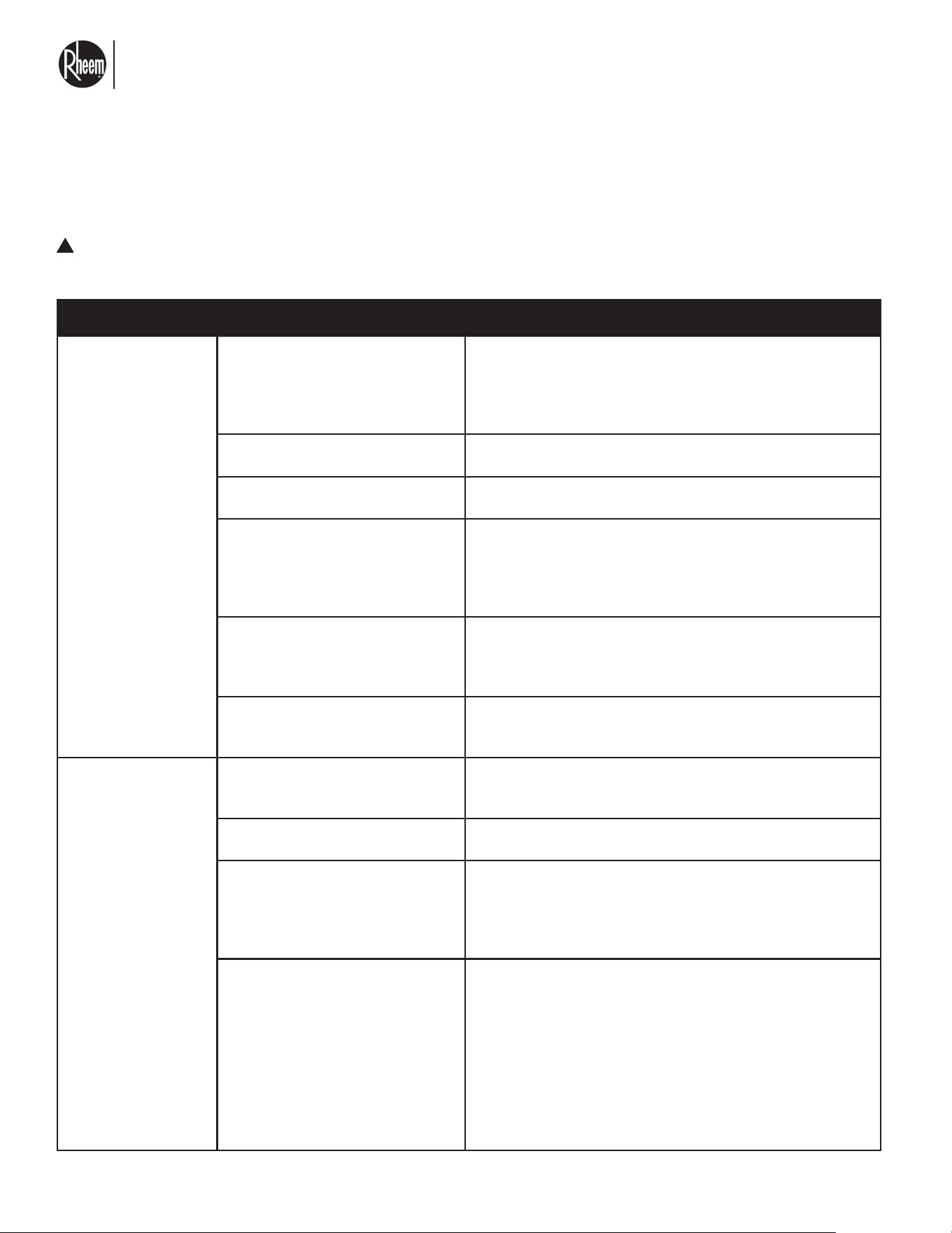
El nuevo grado de confort.
MR
Commercial HEAT PUMP WATER HEATER MONOBLOCK - I&O MANUAL
Page 49
6.1 WHAT DO TO IN CASE OF FAILURES
GENERAL TROUBLESHOOTING
WARNING: Disconnect all power to unit before servicing. Failure to shut off power can cause
electrical shock resulting in personal injury or death.
!
SYMPTOM POSSIBLE CAUSE REMEDY
Insufficient heating
Water flow is too high
1. Confirm water flow is align with desired water outlet
temperature and heating mode.
2. Confirm unit circulator and make sure it is operating
on/off mode and not based on temperature differential
from external sensors.
Incorrect heat pump mode
setting
1. Confirm that the right mode of operation is selected
according to the piping of the water heating system.
Unit in failure state
1. Confirm that no error codes exist in the system, use
the Sky-35 display.
Poor ventilation around unit
1. Ensure that unit has proper clearances to allow
adequate airflow through the system.
2. Verify that no obstructions exist around the
evaporator coil, excessive dirt, leaves, or stuck plastic
bags causing blockage.
Unit poorly charged
1. Review system charge by checking superheat during
heating cycle, a value between 8 to 16 is normal.
Superheat values higher than 30°F can mean low
system charge.
Under size system or storage
tank
1. Confirm that storage tank capacity and system
flows are sized properly for the capacity of the unit
installed.
Compressor short
cycle
Oversized system
1. System capacity exceeds the demand, causing the
unit to reach set point rapidly. Confirm that system is
sized properly
Incorrect heat pump mode
setting
1. Confirm that the right mode of operation is selected
according to the piping of the water heating system.
Water flow issue
1. Review water flow and make sure there are no air
bubbles on the system that could cause air gaps.
Purge the system.
2. Make sure water circulator is operating properly and
that adequate and constant water flow exists.
Compressor over current
1. Monitor current of the system, it should not exceed 40
amps during the heat cycle.
2. Review system charge by checking superheat during
heating cycle, a value between 8 to 16 is normal.
Superheat values lower than 2°F can mean excessive
system charge.
3. Check system discharge pressure, pressures in
excess of 550psi, can mean reduced water flow,
high charge of system or possible water pipe partial
blockage.
El nuevo grado de confort.
MR
Commercial HEAT PUMP WATER HEATER MONOBLOCK - I&O MANUAL
Page 50
6.1 WHAT DO TO IN CASE OF FAILURES
GENERAL TROUBLESHOOTING
WARNING: Disconnect all power to unit before servicing. Failure to shut off power can cause
electrical shock resulting in personal injury or death.
!
SYMPTOM POSSIBLE CAUSE REMEDY
Compressor short
cycle
Blockage in refrigeration system
1. Main EEV might be fully closed, causing low pressure
to drop and cause freezing.
2. Check that main expansion valve control is properly
connected to the board and properly mounted on the
electronic expansion valve assembly.
Excessive frost
formation on unit
Fan not working
1. Check fan connections to the main control board and
to power terminal block.
2. Verify fan motor windings by measuring coil
resistance, see wiring diagram for motor winding
leads.
3. Confirm fan spinning direction, air should be expelled
from the top of the unit.
Unit charge low
Review system charge by checking superheat during
heating cycle, a value between 8 to 16 is normal.
Superheat values higher than 30°F can mean system is
low on charge.
Inadequate defrost sensor
location
Verify that evaporator and suction temperature
thermistors are not loose or have been detached from
the pipes.
Discharge bypass valve not
working
1. Bad vapor bypass valve coil. Check wiring diagram
and measure resistance of the coil.
2. Confirm that vapor bypass is active, this can be
forced from the Sky-35 screen display.
High discharge,
normal suction
pressure
Water flow
Confirm water flow is at least 5GPM and is flowing in
the right direction.
Unit configuration setting
Confirm the heat pump is configured so that it matches
the piping configuration, single or multipass.
Water outlet temperature sensor
1. Confirm that water outlet temperature sensor is firmly
installed against water pipe.
2. Check sensor wiring to control board. Make sure
connector is fully inserted and there are no loose
wires.
3. Measure sensor resistance, resistance should be
10 k ohm at ambient temp (70°F). As temperature
increases on sensor, resistance value should lower.
El nuevo grado de confort.
MR
Commercial HEAT PUMP WATER HEATER MONOBLOCK - I&O MANUAL
Page 51
6.1 WHAT DO TO IN CASE OF FAILURES
GENERAL TROUBLESHOOTING
WARNING: Disconnect all power to unit before servicing. Failure to shut off power can cause
electrical shock resulting in personal injury or death.
!
SYMPTOM POSSIBLE CAUSE REMEDY
Low suction
pressure, iced
indoor coil
Fan not working
1. Check fan connections to the main control board and
to power terminal block.
2. Verify fan motor windings by measuring coil
resistance, see wiring diagram for motor winding
leads.
3. Confirm fan spinning direction, air should be expelled
from the top of the unit.
Unit charge low
Review system charge by checking superheat during
heating cycle, a value between 8 to 16 is normal.
Superheat values higher than 30°F can mean system is
low on charge.
Partial evaporator blockage
Verify that no obstructions exist around the evaporator
coil, excessive dirt, leaves, or stuck plastic bags
causing blockage.
Electronic expansion valve (EEV)
1. Main EEV might be fully closed, causing low pressure
to drop to freezing.
2. Check that main expansion valve control is properly
connected to the board and properly mounted on the
electronic expansion valve assembly.
Fluctuating head
and suction
pressures
Electronic expansion valve
1. Main EEV might be acting erratically, check that
stepper motor is firmly installed on valve stem.
2. Check that main EEV is properly connected to the
control board and installed properly mounted on the
electronic expansion valve assembly.
Suction temperature sensor
1. Confirm that suction temperature sensor is firmly
installed on copper pipe and that insulation is
installed properly.
2. Check sensor wiring to control board. Make sure
connector is fully inserted and there are no loose
wires.
3. Measure sensor resistance, resistance should be
10 k ohm at ambient temp (70°F). As temperature
increases on sensor, resistance value should lower.
Poor ventilation around unit
1. Ensure that unit has proper clearances to allow
adequate airflow through the system.
2. Verify that no obstructions exist around the
evaporator coil, excessive dirt, leaves, or stuck plastic
bags causing blockage.
Suction pressure transducer
1. Confirm that pressure transducer is properly installed
on the threaded connector.
2. Verify that the connector on the control board is fully
inserted and no wires are loose.
El nuevo grado de confort.
MR
Commercial HEAT PUMP WATER HEATER MONOBLOCK - I&O MANUAL
Page 52
GENERAL TROUBLESHOOTING
WARNING: Disconnect all power to unit before servicing. Failure to shut off power can cause
electrical shock resulting in personal injury or death.
!
SYMPTOM POSSIBLE CAUSE REMEDY
Excessive vibration/
noise from unit
Mechanical installation
1. Verify that all straps, brackets are properly installed
and securely fastened.
2. Purge water lines until only water comes out.
3. Make sure unit is level and sitting on a flat surface.
4. Confirm fan blade is not damaged and that it is
spinning properly and balanced.
Bubbles in water line
1. Make sure that there are no bubbles in water line.
2. Purge water lines until only water comes out of the
lines.
Faulty Compressor
Electrical installation
1. Confirm correct voltage, phase and frequency are
connected to the water heater. If using a step-down or
up transformer, confirm output voltage matches unit
nameplate.
2. Overvoltage might damage the compressor.
3. Contact manufacturer for further information.
Unit charge low
1. Review system charge by checking superheat during
heating cycle, a value between 8 to 16 is normal.
Superheat values higher than 30°F can mean system
is low on charge.
2. Contact manufacturer for further information.
6.1 WHAT DO TO IN CASE OF FAILURES
El nuevo grado de confort.
MR
Commercial HEAT PUMP WATER HEATER MONOBLOCK - I&O MANUAL
Page 53
6.2 ERROR CODES
ALERT / ALARM
CODE
DESCRIPTION POSSIBLE CAUSE ACTION
A001_W Model Data
Configuration Error
Error on model data file Data corruption
Shutdown - contact your
Rheem authorized dealer
A002_V Vapor Inlet
Temperature Sensor
Fault
Vapor inlet temperature
sensor failed.
Sensor disconnected or shorted.
Shutdown - check sensor
wires measure resistance
between 1K and 729 kOhms
A003_V Vapor Outlet
Temperature Sensor
Fault
Vapor Outlet temperature
sensor failed
Sensor disconnected or shorted.
Shutdown - check sensor
wires measure resistance
between 1K and 729 kOhms
A004_W Outlet
Temperature Over
Limit
Outlet temperature
exceeds 175F
Bad water outlet sensor or loose
from pipe. Water flow through unit
is not optimal.
Check water sensor
placement and that no
obstruction exist on water
pipe.
A007_W
Hydra Control
Communication Fault
Communication error
Wiring issue between main
control and expansion board.
Shutdown - Review wiring
between main control board
and expansion board.
A008_W Sky-35
Communication Fault
Lost communication with
SKY-35 main controller
device
Communication with SKY-35
restore
Unit will shut down
If enabled, unit will enter
a limp mode, 12 minutes
standby, then start heating.
Unit will use last known
setpoint.
A009_W Maximum
Delta Temperature
Exceeded
Delta between water outlet
and inlet is too high
• Little or not flow through unit.
• Water temp sensor failed.
Shutdown - check water flow,
pump and water temperatures
sensors.
T010_S Clean Unit
Reminder
Service reminder
Perform system service and
cleaning.
Send to SKY-35
T012_S Clean Drain
Tap
Condensate drain trap
cleaning
Clean up system drain. Send to SKY-35
A019_W Low
Ambient Temperature
Notice
Ambient temperature too
high <-15°F
Ambient temperature too low
Locked out - unit will not
operate
A020_W High
Ambient Temperature
Notice
Ambient temperature too
high >115°F
Ambient temperature too high
Locked out - unit will not
operate
T021_W Low Suction
Temperature
Suction temperature is
abnormally low
• Incorrect or no water flow
• Fan not running
• Ambient temperature too low
• Suction temperature sensor
damaged.
Shutdown
A022_W Low
Superheat alarm
Unit superheat is
abnormally low.
• Incorrect or no water flow
• Fan not running
• Ambient temperature too low
• Suction temperature sensor
damaged.
• System is overcharged.
Shutdown - 3 strikes lockout
A031_W Water Inlet
Temperature Sensor
Fault
Water inlet temperature
sensor failed
Sensor disconnected or shorted.
Shutdown - check sensor
wires measure resistance
between 1K and 729 k Ohms
El nuevo grado de confort.
MR
Commercial HEAT PUMP WATER HEATER MONOBLOCK - I&O MANUAL
Page 54
ALERT / ALARM
CODE
DESCRIPTION POSSIBLE CAUSE ACTION
A032_W Water Outlet
Temperature Sensor
Fault
Water outlet temperature
sensor failed
Sensor disconnected or shorted.
Shutdown - check sensor
wires measure resistance
between 1K and 729 k Ohms
A033_W Evaporator
Temperature Sensor
Fault
Evaporator temperature
sensor failed
Sensor disconnected or shorted.
Shutdown - check sensor
wires measure resistance
between 1K and 729 k Ohms
A036_W Suction
Pressure Transducer
Fault
Pressure detected at then
suction side is 0
Sensor is disconnected or there's
voltage drop across the wires
Shutdown - check wires
harness for wire damage and
proper insertion on pressures
transducer.
A037_W Liquid
Pressure Transducer
Fault
Pressure detected at the
discharge side is 0
Sensor is disconnected or there's
voltage drop across the wires
Shutdown - check wires
harness for wire damage and
proper insertion on pressures
transducer.
A038_W Water Flow
Sensor Fault
Water flow is not detected
by the unit after a heat
demand is started.
• No flow of water
• Sensor disconnected or loose
• Obstruction on the piping
Shutdown - check for
correct connection between
unit and circulator. Check
circulator voltage, check no
obstructions on piping. Check
wiring.
A039_W Suction
Temperature Sensor
Fault
Suction temperature
sensor failed
Sensor disconnected or shorted.
Shutdown - check sensor
wires measure resistance
between 1K and 729 kOhms
A041_W Discharge
Sensor Fault
Discharge temperature
sensor failed
Sensor disconnected or shorted.
Shutdown - check sensor
wires measure resistance
between 1K and 729 kOhms
A042_W Ambient
Sensor Fault
Ambient temperature
sensor failed
Sensor disconnected or shorted.
Shutdown - check sensor
wires measure resistance
between 1K and 729 kOhms
A050_W Refrigerant
Pressure Ratio Fault
Compression ratio for unit
is lower than required.
• Incorrect system charge
• Incorrect temperature /pressure
readings.
Shutdown - 3 strikes lockout
A051_W Low
Discharge Superheat
Fault
Discharge superheat is
lower than required for
extended period of time.
• Incorrect system charge
• Incorrect temperature /
pressure readings.
• Vapor injection circuit failure.
Shutdown - Check proper
sensor installation discharge
thermistor and liquid pressure
transducer.
Review system proper charge.
A093_W Model Data
Restore Failure
Model Data is corrupt or
not present
Data corruption
Shutdown - contact your
Rheem authorized dealer
T101_W Inverter
Fault - Compressor
Overcurrent
Over current sensed by
inverter
• Compressor is drawing too
much current.
• Water flow is not optimal for
unit, usually too low.
• Water returning to unit is too
hot.
Shutdown - unit will
permanently lock after
experiencing this alarm 3
times.
A102_W Inverter
Fault - IPM Temp
Sensor Fault
Over temperature alarm
• Failure on fan motor
• Inverter failure
Shutdown - check proper fan
operation, check inverter LED
codes.
6.2 ERROR CODES
El nuevo grado de confort.
MR
Commercial HEAT PUMP WATER HEATER MONOBLOCK - I&O MANUAL
Page 55
6.2 ERROR CODES
ALERT / ALARM
CODE
DESCRIPTION POSSIBLE CAUSE ACTION
A104_W Inverter
Fault - PFC Temp
Sensor Fault
Over temperature alarm
• Failure on fan motor
• Inverter failure
Shutdown - check proper fan
operation, check inverter LED
codes.
A106_W Inverter
Fault - DC Bus
Voltage High
DC output voltage to
compressor is too high
Check proper voltage delivery
from power supply
Shutdown - unit will
permanently lock after
experiencing this alarm 3
times.
A107_W Inverter
Fault - DC Bus
Voltage Low
DC output voltage to
compressor is too low
Check proper voltage delivery
from power supply
Shutdown - unit will
permanently lock after
experiencing this alarm 3
times.
A109_W Inverter
Fault - Comm. Lost
W/Contoller
Communication error
Wiring issue between inverter
driver and main control board
Shutdown - Review wiring
between main control board
and inverter board.
A110_W Inverter
Fault - AC Under
Voltage
AC input voltage too low
Check proper voltage delivery
from power supply
Shutdown
A111_W Inverter
Fault - AC Over
Voltage
AC input voltage too high
Check proper voltage delivery
from power supply
Shutdown
A112_W Inverter
Fault - AC Current
High
High current demanded
from Inverter
Damaged compressor, incorrect
water flow, high water inlet
temperature.
Shutdown - 3 strikes for
lockout.
A114_W Inverter
Fault - Current
Detection Fault
Inverter fault Contact Rheem dealer Shutdown
A116_W Inverter
Fault - IPM Over
Temperature
Over temperature alarm
• Failure on fan motor
• Inverter failure
Shutdown - check proper fan
operation, check inverter LED
codes.
A117_W Inverter
Fault - IPM Over
Current
Over current alarm
• Failure on fan motor
• Inverter failure
Shutdown - check proper fan
operation, check inverter LED
codes.
A119_W Inverter
Fault - Compressor
Failed Start
Compressor fault Contact Rheem dealer
Locked out - unit will not
operate
A120_W Inverter
Fault - AC Input
Phase Fault
Loss or incorrect phase
Review power wiring for correct
phase and power supply for
dropped out phase.
Shutdown
A122_W Inverter
Fault - Compressor
Phase Lost
Loss of phase at the
compressor connections
Review compressor wiring
Shutdown - contact your
Rheem authorized dealer
A123_W Inverter
Fault - PFC Over
Temperature
Inverter fault Contact Rheem dealer
Shutdown - 3 strikes
for lockout - Fan runs
continously.
A124_W Inverter
Fault - DC Hardware
Protection
Inverter fault Contact Rheem dealer Shutdown
El nuevo grado de confort.
MR
Commercial HEAT PUMP WATER HEATER MONOBLOCK - I&O MANUAL
Page 56
ALERT / ALARM
CODE
DESCRIPTION POSSIBLE CAUSE ACTION
A125_W Inverter
Fault - AD Offset
Fault
Inverter fault Contact Rheem dealer Shutdown
A126_W Inverter
Fault - Speed
Misalignment
Compressor fault Contact Rheem dealer
Shutdown - 3 strikes for
lockout
A128_W Inverter
Fault - Compressor
Sync Failure
Compressor or inverter
fault
Contact Rheem dealer Shutdown
A129_W Inverter
Fault - Compressor
Model Error
Compressor or inverter
fault
Contact Rheem dealer Shutdown
A311_S Refrigerant
Detected Sensor 1
Refrigerant has been
detected within the unit
vicinity.
• Leak on the system.
• Possible leak from a nearby
refrigerant storage tank. "
Shutdown - unit will keep
fan turned of to dissipate
refrigerant gas.
A812_W Inverter
Fault - Drive Failure
Inverter fault Contact Rheem dealer Shutdown
A928_W Locked Out
- See History Faults
Any active 3 strikes
lockout alarm
Clear the alarms or cycle power Permanent Lockout
A929_W Inverter
Communication Fault
Inverter fault Contact Rheem dealer
Shutdown - Check the
connection between main
control board and inverter.
Also check transformer power
wires (YL and BU wires)
T957_W Low
Refrigerant Pressure
Suction pressure is low.
• Fan failure
• Incorrect system charge
• Bad compressor or inverter
Shutdown - 3 strikes for
lockout
T958_W High
Refrigerant Pressure
Refrigerant discharge
pressure is abnormally
high
• Incorrect or no water flow
• Fan not running
• Water inlet too hot
• Discharge temperature sensor
damage
Shutdown - 3 strikes for
lockout
T959_W High Suction
Pressure
Suction pressure is too
high
• Incorrect system charge
• Incorrect temperature /
pressure readings
• Ambient too hot
Shutdown - 3 strikes for
lockout
A972_W Compressor
Discharge Temp High
Refrigerant discharge
temperature too high
• Incorrect or no water flow
• Fan not running
• Water inlet too hot
• Discharge temperature sensor
damage
• Refrigerant charge may be low
Shutdown - 3 strikes for
lockout. Check water pump
for proper operation. Confirm
water inlet is not excessively
high.
Check for leaks in the system.
T986_W High
Refrigerant Pressure
Envelope
Liquid pressure is high
• Incorrect or no water flow
• Fan not running
• Water inlet too hot
Shutdown - 3 strikes for
lockout. Check water pump
for proper operation. Confirm
water inlet is not excessively
high.
6.2 ERROR CODES
El nuevo grado de confort.
MR
Commercial HEAT PUMP WATER HEATER MONOBLOCK - I&O MANUAL
Page 57
Any replacement part used to replace parts origi-
nally supplied on equipment must be the same
as or an approved alternate to the original part sup-
plied. The manufacturer will not be responsible
for replacement parts not designed to physically fit or
operate within the design parameters the original parts
were selected for.
WARNING: Work shall be undertaken under a con-
trolled procedure so as to minimize the risk of a flam-
mable gas or vapor being present while the work is be-
ing performed.
WARNING: all maintenance staff and other workers
in the vicinity where the unit is being repaired, need
to be instructed of the nature of the work being done.
Work in confined spaces shall be avoided.
WARNING: The area of work shall be continuously
monitored with an appropriate refrigerant detector pri-
or to and during the work, to ensure technician is safe
and aware of potential toxic or flammable refrigerants.
Make sure that leak detection device is suitable for
use with R-454B. Make sure there's enough ventilation
around the area where work is performed.
WARNING: Always have a dry powder CO
2
fire extin-
guisher adjacent to the work area, when brazing into
refrigerant system.
WARNING: Do not smoke or use other sources of
ignition, other than the brazing torch, when making re-
pairs to the system.
WARNING: When recharging the system, do not
charge with more refrigerant than what it is listed on
the rating plate.
WARNING: DO NOT use an open flame (torch, or
other naked flame) to detect refrigerant leaks.
WARNING: All components must be replaced by a
qualified technician. All electrical components are not
serviceable and should be replaced as soon as failure
occurs.
REPLACEMENT PARTS
ITEM DESCRIPTION PART NUMBER RMHPHDA068 RMHPHDA120 QTY. NOTES
1 Main expansion valve 35 kW 61-109611-01 X 1
2 Vapor injection valve 35 kW / 20 kW 61-110099-01 X 1
3 Main expansion valve 20 kW 61-109610-01 X 1
4 Main EEV valve coil 61-109663-01 X 1
5 Vapor injection EEV coil 61-109664-02 X 1
6 Main EEV coil 20 kW 61-109664-01 X 1
7 Compressor 35 kW 55-109605-01 X 1
8 Compressor 20 kW 55-109606-01 X 1
9 High pressure switch 47-110094-01 X 1
10 Liquid pressure sensor harness 45-104130-05 X 1
11 Liquid pressure sensor 47-103454-01 X 1 Order item 10 If wire harness is need
12 Discharge temperature sensor 47-110097-01 X 1
13 Suction pressure sensor harness 45-104130-03 X 1
14 Suction pressure sensor 47-103454-05 X 1 Order item 13 If wire harness is need
15 Suction and evaporator sensor 47-108211-06 X 1
16 Defrost valve coil 61-103961-02 X 1
17 Defrost valve 61-103961-16 X 1
18 Economizer condenser 65-109785-01 X 1
When ordering this part, please also order items
19 and 20
19 Economizer insulation part A 68-109720-01 X 1
20 Economizer insulation part B 68-109765-01 X 1
21 Liquid line lter drier 83-104826-08 X 1
7.0 REPLACEMENT PARTS
!
!
!
!
!
!
!
!
El nuevo grado de confort.
MR
Commercial HEAT PUMP WATER HEATER MONOBLOCK - I&O MANUAL
Page 58
7.0 REPLACEMENT PARTS
REPLACEMENT PARTS
ITEM DESCRIPTION PART NUMBER RMHPHDA068 RMHPHDA120 QTY. NOTES
22 Control relay SPDT 42-19737-01 X 1
23 Transformer 75 VA 46-110061-01 X 1
24A Universal control board 47-109780-01A X 1
24B Universal control board 47-109780-01B X 1
25 VFD power Choke 46-109786-01 X 1
26
Variable frequency driver (inverter)
- 35 kW
47-109788-01 X 1
27
Variable frequency driver (inverter)
- 20 kW
47-109787-01 X 1
28 Main power terminal block 45-21134-04 X 1
29 Hydronic control board 47-109923-01 X 1
30 Filter board (EMI) 47-109723-01 X 1
31 Ambient air sensor 47-102709-10 X 1
32 24 VAC power terminal block 45-106539-01 X 1
33 External connection terminals 100-10000884 X 6 When ordering this part, also order part 34
34 Terminals teminator blocks 100-10000885 X 2
35 Regal fan motor 51-100998-56 X 1
36 Motor wire conduit 68-100930-11 X 1
37 Fan blade 26" 70-101323-29 X 1
38 Wire grille 95-110082-01 X 1
39 Cranckase heater 35 kW 44-109748-01 X 1
40 Cranckase heater 20kW 44-109748-02 X 1
41 Condenser 35 kW 65-109784-01 X 1
When ordering this part, please also order items
42 and 43
42 Condenser insulation part A 68-109762-01 X 1
43 Condenser insulation part B 68-109745-01 X 1
44 Condenser 20 kW 65-109617-01 X 1
When ordering this part, please also order items
45 and 46
45 Condenser insulation part A 68-109761-01 X 1
46 Condenser insulation part B 68-109744-01 X 1
47 Water Flow switch 47-110067-01 X 1
48 Water pipe tting 82-110086-01 X 1
49 Water pipe press tting 82-110078-01 X 1
50 A2L sensor 47-109642-01 X 1 Order item 51 if harness is required.
51 A2L sensor harness 45-110064-01 X 1
52 Cranckase heater relay 45-109900-01 X 1
53 Cranckase heater main power (460V) 45-109901-01 X 1
54 Defrost valve power harness 45-109902-01 X 1
55 Power 460V to VFD 45-109904-01 X 1
56 Solenoid valve coil 61-103961-13 X 1
57 Communication harness 20 kW 45-109906-01 X 1
58 24 Vac power supply wires 20 kW 45-109907-01 X 1
59 24 Vac power supply wires 35 kW 45-109908-01 X 1
60
Water in/out, variable speed fan and
pump harness
45-109910-01 X 1
61
Hydra Power and single speed pump
harness
45-109912-01 X 1
62 Communication harness 35 kW 45-109916-01 X 1
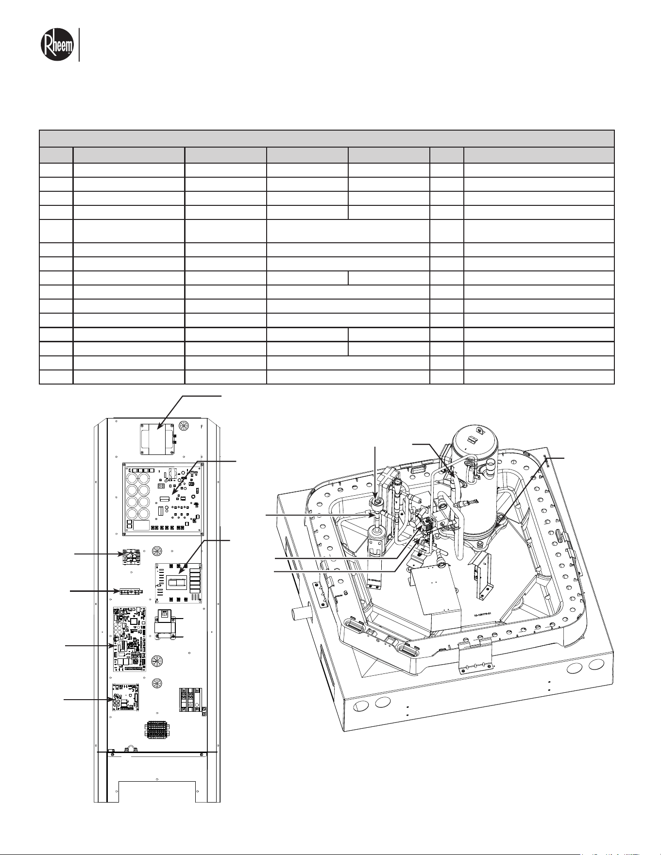
El nuevo grado de confort.
MR
Commercial HEAT PUMP WATER HEATER MONOBLOCK - I&O MANUAL
Page 59
7.0 REPLACEMENT PARTS
REPLACEMENT PARTS
ITEM DESCRIPTION PART NUMBER RMHPHDA068 RMHPHDA120 QTY. NOTES
63 VFD to choke harness 35 kW 45-109918-01 X 1
64 Fan relay harness 20 kW 45-109920-01 X 1
65 Main 460V power to EMI lter 35 kW 45-109949-01 X 1
66 Power to VFD 35 kW 45-110060-01 X 1
67
Brackets for hurricane or seismic
tie down
10-105931-02 X 6
When ordering this part, please order items on
line 68
68 Tie down screws 63-105938-01 X 30
69 Water temperature sensors 47-109941-01 X 1
70 Charge accumulator 83-108723-02 X 1
71 Bypass solenoid valve 61-103961-10 X 1
72 Tank well thermistor 011932 X 1 Order depending on your needs
73 System water circulator VM3450-DD1-RS2W00 X 1 Sugested sytem circulator
74 Power transformer 30 KVA T3030K0013B X 1 Suggested step up transformer*
75 Power transformer 45 kVA T3045K0013B X 1 Suggested step up transformer*
76 Nipple with indexed diffuser 2" AP18971 X 1
77 Solenoid valve water inlet USS-MSV00009 X 1 Suggested shut off valve, 1 per unit.
25
17
16
3
12
40
7
4
1
5
8
27
30
23
26
22
32
24A
24B
33
34
28
29
31
39
NOTE: Images may differ in appearance from the actual product.
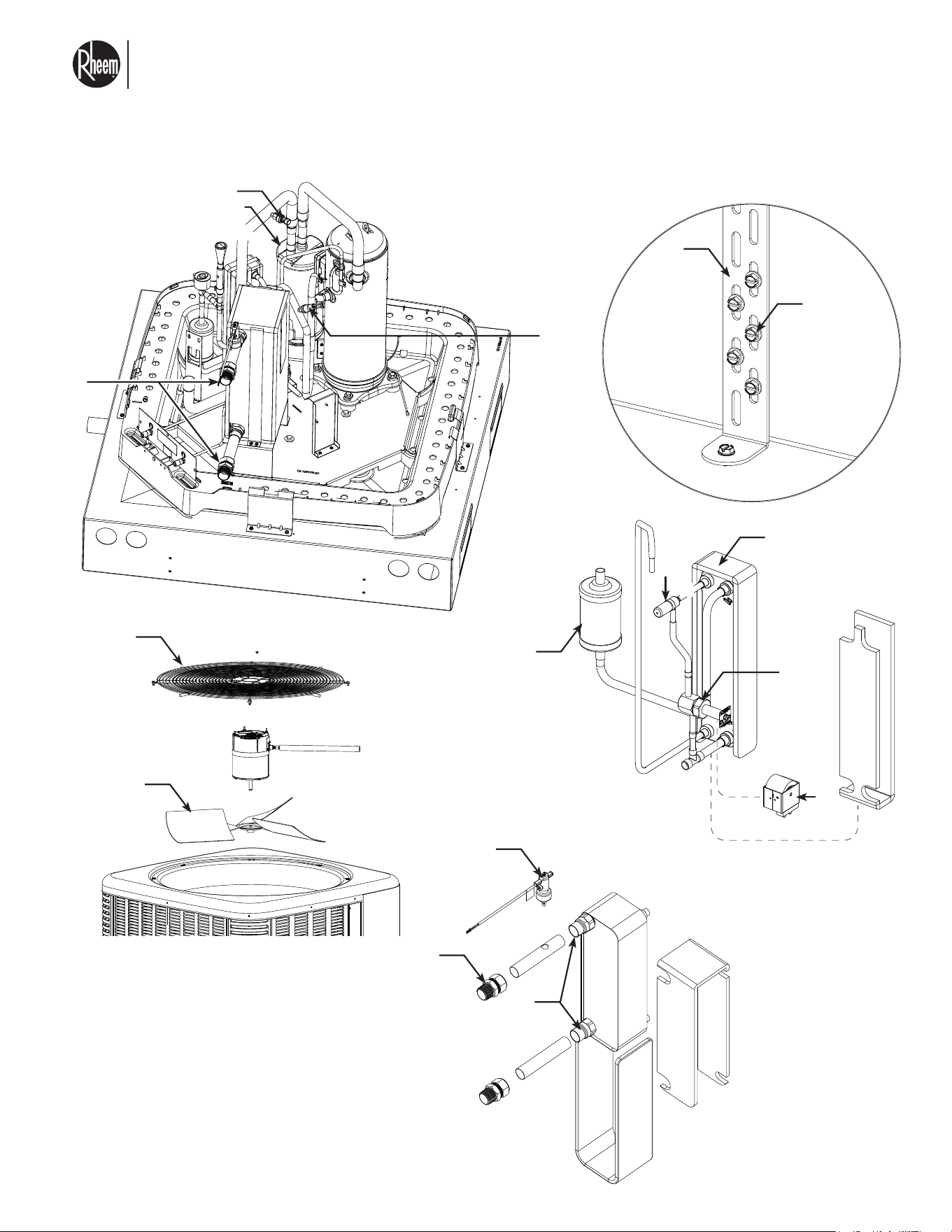
El nuevo grado de confort.
MR
Commercial HEAT PUMP WATER HEATER MONOBLOCK - I&O MANUAL
Page 60
38
9
69
14
70
37
35
36
67
68
20
47
49
48
45
44
41
42
43
46
21
56
71
69
2
18
19
NOTE: Images may differ in appearance
from the actual product.
7.0 REPLACEMENT PARTS
15

El nuevo grado de confort.
MR
Commercial HEAT PUMP WATER HEATER MONOBLOCK - I&O MANUAL
Page 61
7.1 BEFORE BEGINNING DECOMMISSIONING
7.2 DECOMMISSIONING PROCEDURE
Before carrying out decommissioning, the technician
performing decommissioning must be familiar with the
equipment and its safety procedures, and ensure elec-
trical power is available to the unit. See Section Work-
ing Personnel on page 65.
Always use new refrigerant if ever recharging system.
DO NOT use reclaimed refrigerant to re-charge.
Before beginning any work on systems containing
flammable refrigerants, safety checks are necessary to
ensure that the risk of ignition is minimized. See sec-
tion 5.2.
Before beginning any work on the system or conduct-
ing any hot work, ensure that the area is in the open or
that it is adequately ventilated. Ventilation must con-
tinue while the unit is being worked on. Ventilation is
required to safely disperse any released refrigerant into
the atmosphere.
Work shall be undertaken under a controlled procedure
so as to minimize the risk of flammable gas or vapor
being present while work is being performed. See sec-
tion Importance of a Quality Installation on page 6.
The area shall be checked with an appropriate refrig-
erant detector before and during work to ensure the
technician is aware of potentially toxic or flammable
atmospheres.
Make sure the correct amount of recovery cylinders are
on hand, to hold the total volume of the unit. Make sure
cylinders are labeled as containing reclaimed refriger-
ant.
Make sure all pressure relief valves on cylinders are in
good condition.
Consult your local guidelines for the disposal of used
refrigerant. DO NOT MIX REFRIGERANTS.
If compressor oil must be removed, ensure system has
been fully evacuated first.
Follow the decommissioning procedure outlined below:
READ ALL STEPS BEFORE BEGINNING.
1. Become familiar with the equipment, its operation,
and its safety procedures.
2. Isolate the system electrically.
3. Ensure that mechanical handling equipment for the
refrigerant cylinders is at hand, if required.
4. Ensure personal, protective equipment is being
used correctly.
5. A competent supervisor must be present during the
refrigerant recovery process. Ensure such a person
is available on site.
6. Confirm that the recovery equipment and cylinders
are correct for the equipment and its refrigerant.
7. If possible, circulate down the refrigerant system.
8. If a vacuum is not possible, make a manifold so
that the refrigerant can be removed from various
parts of the system.
9. Make sure that the recovery cylinder is situated on
the scale before recovery begins.
10. Start the recovery machine and operate it in accor-
dance with its instructions.
11. Do not overflow the cylinders. No more than 80%
volume liquid charge is allowed.
12. Do not exceed the maximum working pressure of
the cylinder, even temporarily.
13. When the cylinders have been filled correctly and
the process is complete, make sure that the cylin-
ders and the recovery equipment are removed from
the site promptly.
14. Recovered refrigerant shall not be charged into an-
other unit.
15. Once refrigerant is recovered, label system as De-
Comissioned. The label shall be dated and signed.
Ensure that there are labels on the systems that
state flammable refrigerant.
When performing any maintenance or troubleshoot-
ing on the refrigerating equipment or associated parts,
a dry powder or CO
2
fire extinguisher shall be nearby
for emergency use. Equipment must be labeled stat-
ing that is has been decommissioned and emptied of
refrigerant. The label must be dated and signed. Ensure
that there are label(s) on the unit stating that this equip-
ment contains flammable refrigerant.

El nuevo grado de confort.
MR
Commercial HEAT PUMP WATER HEATER MONOBLOCK - I&O MANUAL
Page 62
8.0 CERTIFICATE OF LIMITED WARRANTY
COMMERCIAL AIR TO WATER HEAT PUMP WATER HEATER
For the Rheem, Ruud, Richmond, or Raypak Models listed
in this Manual.
GENERAL
This Limited Warranty is only available to the original
owner of this water heater. It is not transferable.
Rheem Manufacturing Company (Rheem®) warrants
this Rheem/Ruud/Richmond/Raypak water heater, and
its component parts, to be free from defects in materials
and workmanship, under normal use and service, for the
Applicable Warranty Period. At its option, Rheem will
repair or replace the defective water heater, or defective
component part(s), in accordance with the terms of this
Limited Warranty, if it fails in normal use and service
during the Applicable Warranty Period. The replace-
ment component part(s) must be Rheem authorized
component part(s). The replacement unit will be war-
ranted only for the unexpired portion of the original
unit’s Applicable Warranty Period.
EFFECTIVE DATE
The Effective Date of warranty coverage (or the begin-
ning of the Applicable Warranty Periods) is the date of
installation of the water heater, if properly documented.
Otherwise, it is the date of manufacture of the water
heater plus ninety (90) days.
APPLICABLE WARRANTY PERIODS
The Applicable Warranty Periods are one (1) year from
the Effective Date for the tank and the component
parts. One year parts only warranty.
WARRANTY EXCLUSIONS
This Limited Warranty will not cover:
a) Service trips to your facility to teach you how to in-
stall, use, or maintain this water heater or to bring the
water heater installation into compliance with local
building codes and regulations.
b) Damages, malfunctions or failures resulting from fail-
ure to install the water heater in accordance with ap-
plicable building codes/ordinances or good plumb-
ing and electrical trade practices.
c) Damages, malfunctions, or failures resulting from im-
proper installation or failure to operate and maintain
the water heater in accordance with the manufac-
turer’s instructions provided.
d) Performance problems caused by improper sizing
of the water heater or (pertaining to electric models)
electric service voltage, wiring, or fusing.
e) Damages, malfunctions, or failures caused by abuse,
accident, fire, flood, freeze, lightning, acts of God,
and the like.
f) Coil failures (leaks) caused by operating the water
heater in a corrosive or contaminated atmosphere.
g) Damages, malfunctions, or failures caused by oper-
ating the water circulator without any supply of wa-
ter.
h) Damages, malfunctions, or failures caused by oper-
ating the unit at water temperatures exceeding the
maximum setting of the operating, or high limit, con-
trol.
i) Coil failures caused by operating the water heater
when it is not supplied with potable water, free to cir-
culate at all times.
j) Damages, malfunctions or failures caused by sub-
jecting the heater to pressures, or electrical charac-
teristics, greater than those shown on the rating label.
k) Damages, malfunctions or failures resulting from the
use of any attachment, including any energy saving
device, not authorized by Rheem.
l) Units installed outside the fifty states (and the District
of Columbia) of the United States of America.
m) Units removed from the original installation location.
n) Units that have had their rating labels removed. A
water heater should not be operated if the rating la-
bel is removed
o) Parts installed with or used in connection with nor-
mal maintenance, such as cleaning or replacing re-
frigerant, or refrigerant drier.

El nuevo grado de confort.
MR
Commercial HEAT PUMP WATER HEATER MONOBLOCK - I&O MANUAL
Page 63
CERTIFICATE OF LIMITED WARRANTY
LABOR, SHIPPING, AND PROCESSING COSTS (Af-
ter 1 Year)
This Limited Warranty does not cover any labor expenses
for service, repairs, reinstallation, permits, or removal and
disposal of the failed water heater, or defective compo-
nent part(s). All such expenses are your responsibility.
Rheem will pay the transportation costs for an “in-war-
ranty” replacement water heater, or “in-warranty” replace-
ment component part(s), to a convenient delivery point
(selected by Rheem) near the place the original water
heater, or original component part(s), is located: such as
a local Rheem/Ruud/Raypak/Richmond water heater dis-
tributor. You must pay any local freight charges, including
the cost of returning the failed water heater, or defective
component part(s) to a convenient shipping location (se-
lected by Rheem): such as a local Rheem/Ruud/Raypak/
Richmond water heater distributor.
Rheem does not authorize, recommend, or receive any
benefit from any claims processing or similar fees charged
by others to process warranty claims for any Rheem wa-
ter heater or component part(s). Rheem will not reimburse
any party for these, or any other, fees not specifically cov-
ered in this Limited Warranty document.
HOW TO OBTAIN WARRANTY CLAIM ASSISTANCE
Any claim for warranty assistance must be made promptly.
First, determine if your water heater is “in- warranty” (that
is, within the Applicable Warranty Period). You can deter-
mine your unit’s warranty status by obtaining the complete
model number, the complete serial number, and the date
of installation of your water heater and then accessing
the “Warranty Verification” information on the web site
(www.raypak.com) or contacting Rheem Commercial Wa-
ter Phone (877) 541-7575) or Raypak Technical Support/
Warranty (805) 278-5300 during normal business hours to
determine if the Applicable Warranty Period has expired.
If your water heater is “in-warranty”, contact the plumber,
or mechanical contractor, that installed it for assistance
with the warranty repairs, or replacement, required. You
may also select a plumber, or mechanical contractor, from
your local Yellow Pages to assist you. Technical Service
personnel are available to assist you on the web site
(www.raypak.com) or contacting Rheem Commercial Wa-
ter Phone (877) 541-7575) or Raypak Technical Support/
Warranty (805) 278-5300 – in obtaining “in-warranty” ser-
vice or to answer your questions about the operation or
repair of your water heater during normal business hours.
Be prepared to provide the plumber, mechanical contrac-
tor, or Technical Service person you contact with the com-
plete model number, the complete serial number, and the
date of installation of your water heater in addition to an
explanation of your water heater problem.
If an exact replacement is not available, Rheem will pro-
vide you with the current model of your water heater, or
component part(s), or a replacement unit with comparable
operating features. If government regulations or industry
certification or similar standards require the replacement
water heater, or replacement component part(s), to have
features not found in the defective water heater, or the
defective component part(s), you will be charged for the
difference in price represented by those required features.
If you pay the price difference for those required features
and/or to upgrade the size and/or other features available
on a replacement new water heater, you will also receive
a complete new Limited Warranty (with the full Applicable
Warranty Period) for the replacement new water heater.
Rheem reserves the right to inspect, or require the return
of, the failed water heater or the defective component
part(s). Each “in-warranty” failure water heater must be
made available to Rheem (with the rating label and all the
component parts intact) in exchange for the replacement
water heater. Each defective “in-warranty” component
part to be replaced must be returned to Rheem in ex-
change for the replacement component part.
Warranty compensation is subject to validation of “in-war-
ranty” coverage by Rheem Claims Department personnel.
• To obtain warranty compensation for an “in-warranty”
water heater failure, you must provide Rheem with: (at
Rheem’s option) either the failed water heater (with
the rating label and all the component parts intact)
or the complete original rating label (photocopies are
not acceptable) removed from the failed water heater;
the complete model number and the complete serial
number of the Rheem/Ruud/Richmond/Raypak wa-
ter heater that replaced the failed unit; and the date
the original water heater failed. You may also be re-
quired to provide documentary proof of the failed
water heater’s date of installation to establish its
“in-warranty” status.
• To receive warranty compensation for an “in-warranty”
defective component part, you must provide Rheem
with: the defective component part; the complete
model number and the complete serial number of the
Rheem/Ruud/Richmond/Raypak water heater from
which the defective component part was removed;
and the date the defective component part failed. You
may also be required to provide documentary proof of
the date of installation of the Rheem/Ruud/Richmond/
Raypak water heater from which the defective part
was removed – or the date of purchase of the part (if it
was purchased separately) - to establish the “in-war-
ranty” status of the defective component part.
El nuevo grado de confort.
MR
Commercial HEAT PUMP WATER HEATER MONOBLOCK - I&O MANUAL
Page 64
EXCLUSIVE WARRANTY – LIMITATION OF LI-
ABILITY
This Limited Warranty is the only Warranty for this unit
given by the Water Heater Division of Rheem Manu-
facturing Company. No one is authorized to make any
other warranties on behalf of Rheem. ANY IMPLIED
WARRANTIES, INCLUDING MERCHANTABILITY, OR
FITNESS FOR A PARTICULAR PURPOSE, SHALL NOT
EXTEND BEYOND THE APPLICABLE WARRANTY PE-
RIODS SPECIFIED PREVIOUSLY. RHEEM’S SOLE LI-
ABILITY, WITH RESPECT TO ANY DEFECT, SHALL BE
AS SET FORTH IN THIS LIMITED WARRANTY, AND
ANY CLAIMS FOR INCIDENTAL OR CONSEQUEN-
TIAL DAMAGES (INCLUDING DAMAGE FROM WATER
LEAKAGE) ARE EXCLUDED. Some states do not allow
limitations on how long an implied warranty lasts, or for
the exclusion of incidental or consequential damages,
so the above limitations or exclusions may not apply
to you.
This Limited Warranty gives you specific legal rights,
and you may also have other rights, which vary from
state to state.
We suggest you immediately complete the information
below and retain this Certificate of Limited Warranty
in the event warranty service is needed. Reasonable
proof of the date of installation of your water heater
may be required to establish its “in-warranty” status.
Otherwise, the Effective Date of this Limited Warranty
will be the date of manufacture of the water heater plus
ninety (90) days.
DO NOT RETURN THIS DOCUMENT TO RHEEM.
KEEP IT WITH YOUR WATER HEATER OR BUSI-
NESS RECORDS.
Name of Owner:
Owner's Address:
Name of Plumber / Mechanical Contractor - Installer:
Address of Plumber / Mechanical Contractor - In-
staller:
Telephone Number of Plumber / Mechanical Contrac-
tor - Installer:
Date of Water Heater Installation:
Model Number of Your Water Heater:
Serial Number of Your Water Heater:
TECHNICAL SUPPORT LINE
Rheem Commercial Water Phone
Phone: (877) 541-7575
Raypak Technical Support/Warranty
805-278-5300
CERTIFICATE OF LIMITED WARRANTY

El nuevo grado de confort.
MR
Commercial HEAT PUMP WATER HEATER MONOBLOCK - I&O MANUAL
Page 65
IF YOU NEED SERVICE
1. Should you have any questions about your new water heater, or if it requires adjustment, repair, or routine mainte-
nance, it is suggested that you first contact your installer, plumbing contractor or previously agreed upon service
agency. In the event that the firm has moved, or is unavailable, refer to the telephone directory commercial listings
or local utility for qualified service assistance.
2. Should your problem not be solved to your complete satisfaction, you should then contact the Manufacturer’s Na-
tional Service Department at one of the following addresses:
In The U.S.A.:
Raypak, Inc.
2151 Eastman Avenue,
Oxnard, CA 93030
Phone: 805-278-5300
When contacting the manufacturer, the following information should be made available:
a. Model and serial numbers of the water heater as shown on the rating plate attached to the jacket of the heater.
b. Address where the water heater is located and can be seen.
c. Name and address of the installer and any service agency who performed service on the water heater.
d. Date of installation invoice or start up documents, indicating start up date and any prior service work.
e. Details of the problem as you can best describe them.
f. List of people, with dates, who have been contacted regarding your problem.
3. Should you have any issue or need assistance with the WiFi Module/EcoNet App then contact the EcoNet Customer
Service:
Phone: 1-800-255-2388
Website: www.Rheem.com/EcoNet
In CANADA:
Rheem Canada, Ltd. / Ltée
125 Edgeware Road, Unit 1
Brampton, ON L6Y 0P5
Phone: 1-800-268-6966.