READ CAREFULLY.
KEEP THESE INSTRUCTIONS
.
31-5000951 Rev. 0 03-25
GE is a trademark of the General Electric Company. Manufactured under trademark license.
NS16H
Heat Pump R-454B
Service
Manual

2 31-5000951 Rev. 0
General Information
These instructions are intended as a general guide and do not supersede national or local codes in any way. Consult
authorities having jurisdiction before installation.
The NS16H model is designed for use with R-454B refrigerant only. This unit must be installed with an approved indoor
air handler or coil. For AHRI Certified system matchups and expanded ratings, visit AHRIDirectory.org.
This outdoor unit is designed for use in systems that use the following refrigerant metering device:
• Check thermal expansion valve (CTXV)
IMPORTANT
Special procedures are required for cleaning the all-aluminum coil in this unit. See page 36 in this instruction for
information.
NOTE – This NS16H unit is a PARTIAL UNIT AIR CONDITIONER, complying with PARTIAL UNIT requirements of this
Standard, and must only be connected to other units that have been confirmed as complying to corresponding PARTIAL
UNIT requirements of this Standard,
UL 60335-2-40/CSA C22.2 No. 60335-2-40, or UL 1995/CSA C22.2 No 236.
31-5000951 Rev. 0 3
Important Safety Information
READ AND SAVE THESE INSTRUCTIONS
WARNING
For your safety; the information in this manual must be followed to minimize the risk of fire,
electric shock, or personal injury.
• Refrigerant can be harmful if it is inhaled. Refrigerant
must be used and recovered responsibly.
• Failure to follow this warning may result in personal
injury or death.
• Improper installation, adjustment, alteration, service
or maintenance can cause property damage, personal
injury or loss of life. Installation and service must be
performed by a licensed professional HVAC installer or
equivalent, service agency, or the gas supplier.
• To prevent serious injury or death:
1. Lock-out/tag-out before performing maintenance.
2. If system power is required (e.g., smoke detector
maintenance), disable power to blower, remove fan
belt where applicable, and ensure all controllers
and thermostats are set to the “OFF” position before
performing maintenance.
3. Always keep hands, hair, clothing, jewelry, tools, etc.
away from moving parts.
• Do not use means to accelerate the defrosting process
or to clean, other than those recommended by the
manufacturer.
• The appliance shall be stored in a room without
continuously operating ignition sources (for example:
open flames, an operating gas appliance, or an operating
electric heater).
• Do not pierce or burn.
• Be aware that refrigerants may not contain an odor.
• Ducts connected to an appliance shall not contain a
potential ignition source.
• Every working procedure that affects safety means shall
only be carried out by competent persons. This appliance
is not to be used by persons (including children) with
reduced physical, sensory or mental capabilities, or
lack of experience and knowledge, unless they have
been given supervision or instruction concerning use of
the appliance by a person responsible for their safety.
Children should be supervised to ensure they do not play
with the appliance.
• Auxiliary devices which may be a potential ignition
source shall not be installed in the duct work. Examples
of such potential ignition sources are hot surfaces with
a temperature exceeding 700°C and electric switching
devices.
• For appliances using A2L refrigerants connected via
an air duct system to one or more rooms, only auxiliary
devices approved by the appliance manufacturer or
declared suitable with the refrigerant shall be installed in
connecting ductwork.
• For duct connected appliances, false ceilings or
drop ceilings may be used as a return air plenum if a
REFRIGERANT DETECTION SYSTEM is provided in
the appliance and any external connections are also
provided with a sensor immediately below the return air
plenum duct joint.
• PARTIAL UNITS shall only be connected to an appliance
suitable for the same refrigerant.
• If this appliance is conditioning a space with an area
smaller than TAmin, then that space must be without
continuously operating open flames (e.g. an operating
gas appliance) or other potential ignition sources (e.g. an
operating electric heater or similar hot surface). A flame-
producing device may be installed in the same space
if the device is provided with an effective flame arrest
system.
• Electric Shock Hazard. Can cause injury
or death. Unit must be properly grounded in
accordance with national and local codes.
Line voltage is present at all components
when unit is not in operation on units
with singlepole contactors. Disconnect
all remote electric power supplies before
opening access panel. Unit may have
multiple power supplies.

4 31-5000951 Rev. 0
Important Safety Information
READ AND SAVE THESE INSTRUCTIONS
CAUTION
• As with any mechanical equipment, contact with sharp
sheet metal edges can result in personal injury. Take
care while handling this equipment and wear gloves and
protective clothing.
• Servicing shall be performed only as recommended by
the manufacturer.
• Under no circumstances shall potential sources of
ignition be used in the searching for or detection of
refrigerant leaks. A halide torch (or any other detector
using a naked flame) shall not be used.
• The following leak detection methods are deemed
acceptable for all refrigerant systems:
• Electronic leak detectors may be used to detect
refrigerant leaks but, in the case of flammable
refrigerants, the sensitivity may not be adequate, or
may need recalibration. (Detection equipment shall
be calibrated in a refrigerant-free area.) Ensure that
the detector is not a potential source of ignition and
is suitable for the refrigerant used. Leak detection
equipment shall be set at a percentage of the LFL of
the refrigerant and shall be calibrated to the refrigerant
employed, and the appropriate percentage of gas (25
% maximum) is confirmed. Leak detection fluids are
also suitable for use with most refrigerants but the use
of detergents containing chlorine shall be avoided as
the chlorine may react with the refrigerant and corrode
the copper pipe-work. If a leak is suspected, all naked
flames shall be removed/extinguished. If a leakage
of refrigerant is found which requires brazing, all of
the refrigerant shall be recovered from the system, or
isolated (by means of shut off valves) in a part of the
system remote from the leak.
• Repair and maintenance to electrical components shall
include initial safety checks and component inspection
procedures such as that capacitors are discharged
in a safe manner to avoid possibility of sparking, that
no live electrical components and wiring are exposed
while charging, recovering, or purging the system, and
that there is continuity of grounding. If a fault exists
that could compromise safety, then no electrical supply
shall be connected to the circuit until it is satisfactorily
dealt with. If the fault cannot be corrected immediately
but it is necessary to continue operation, an adequate
temporary solution shall be used that is reported to the
owner of the equipment, so all parties are advised.
• No person carrying out work in relation to a refrigerating
system which involves exposing any pipe work shall
use any sources of ignition in such a manner that it may
lead to the risk of fire or explosion. All possible ignition
sources, including cigarette smoking, should be kept
sufficiently far away from the site of installation, repairing,
removing and disposal, during which refrigerant can
possibly be released to the surrounding space. Prior to
work taking place, the area around the equipment is to
be surveyed to make sure that there are no flammable
hazards or ignition risks. “No Smoking” signs shall be
displayed.
• Sealed electrical components shall be replaced, not
repaired.
• Intrinsically safe components must be replaced, not
repaired.
• Some soaps used for leak detection are corrosive to
certain metals. Carefully rinse piping thoroughly after
leak test has been completed. Do not use matches,
candles, flame or other sources of ignition to check for
gas leaks.
31-5000951 Rev. 0 5
Important Safety Information
READ AND SAVE THESE INSTRUCTIONS
IMPORTANT
• This unit must be matched with an indoor coil as specified
with AHRI. For AHRI Certified system match-ups, visit
AHRIDirectory.org.
• Ensure that the area is in the open or that it is adequately
ventilated before breaking into the system or conducting
any hot work. A degree of ventilation shall continue
during the period that the work is carried out.
• Verify cabling will not be subject to wear, corrosion,
excessive pressure, vibration, sharp edges or any other
adverse environmental effects.
• Pipe work, including piping material, pipe routing,
and installation shall include protection from physical
damage in operation and service, and be in compliance
with national and local codes and standards, such as
ASHRAE 15, ASHRAE 15.2, IAPMO Uniform Mechanical
Code, ICC International Mechanical Code, or CSA B52.
All field joints shall be accessible for inspection prior to
being covered or enclosed.
• Work shall be undertaken under a controlled procedure
so as to minimize the risk of a flammable gas or vapor
being present while the work is being performed.
NOTE: All maintenance staff and others working in the
local area shall be instructed on the nature of work being
carried out with work in confined spaces being avoided.
• The area shall be checked with an appropriate refrigerant
detector prior to and during work, to ensure the technician
is aware of potentially toxic or flammable atmospheres.
Ensure that the leak detection equipment being used
is suitable for use with all applicable refrigerants, i. e.
nonsparking, adequately sealed or intrinsically safe.
• If any hot work is to be conducted on the refrigerating
equipment or any associated parts, the appropriate fire
extinguishing equipment shall be available to hand.
Have a dry powder or CO2 fire extinguisher adjacent to
the charging area.
• Where electrical components are being changed,
they shall be fit for the purpose and to the correct
specification.
• At all times the manufacturer’s maintenance and service
guidelines shall be followed. If in doubt, consult the
manufacturer’s technical department for assistance.
• The following checks shall be applied to installations
using FLAMMABLE REFRIGERANTS as applicable:
1. The actual refrigerant charge is in accordance with the
room size within which the refrigerant containing parts
are installed.
2. The ventilation machinery and outlets are operating
adequately and are not obstructed.
3. If an indirect refrigerating circuit is being used, the
secondary circuit shall be checked for the presence
of refrigerant.
4. Markings on the equipment should be visible and
legible. Markings and signs that are illegible shall be
corrected.
5. Refrigerating pipe or components are installed in a
position where they are unlikely to be exposed to any
substance which may corrode refrigerant containing
components, unless the components are constructed
of materials which are inherently resistant to being
corroded or are suitably protected against being so
corroded.
• When breaking into the refrigerant circuit to make
repairs – or for any other purpose – conventional
procedures shall be used. However, for flammable
refrigerants it is important that best practice be followed
and, since flammability is a consideration, procedures
such as safely remove refrigerant following local and
national regulations, purging the circuit with inert gas,
evacuating (optional for A2L), purging with inert gas
(optional for A2L), or opening the circuit by cutting or
brazing be adhered to. The refrigerant charge shall
be recovered into the correct recovery cylinders if
venting is not allowed by local and national codes.
For appliances containing flammable refrigerants, the
system shall be purged with oxygen-free nitrogen to
render the appliance safe for flammable refrigerants.
This process might need to be repeated several
times. Compressed air or oxygen shall not be used for
purging refrigerant systems. For appliances containing
flammable refrigerants, refrigerants purging shall be
achieved by breaking the vacuum in the system
with oxygenfree nitrogen and continuing to fill until
the working pressure is achieved, then venting to
atmosphere, and finally pulling down to a vacuum
(optional for A2L). This process shall be repeated until
no refrigerant is within the system (optional for A2L).
When the final oxygenfree nitrogen charge is used, the
system shall be vented down to atmospheric pressure
to enable work to take place. Ensure that the outlet for
the vacuum pump is not close to any potential ignition
sources and that ventilation is available.

6 31-5000951 Rev. 0
Important Safety Information
IMPORTANT
Cont.
• In addition to conventional charging procedures, the
following requirements shall be followed.
– Ensure that contamination of different refrigerants
does not occur when using charging equipment. Hoses
or lines shall be as short as possible to minimize the
amount of refrigerant contained in them.
– Cylinders shall be kept in an appropriate position
according to the instructions.
– Ensure that the REFRIGERATING SYSTEM is
grounded prior to charging the system with refrigerant.
– Label the system when charging is complete (if not
already).
– Extreme care shall be taken not to overfill the
REFRIGERATING SYSTEM.
• Prior to recharging the system, it shall be pressure
tested with the appropriate purging gas. The system
shall be leak tested on completion of charging, but prior
to commissioning. A follow up leak test shall be carried
out prior to leaving the site.
• Prior to beginning work on systems containing flammable
refrigerants, safety checks are necessary to ensure that
the risk of ignition is minimized.
• During repairs to sealed components, all electrical
supplies shall be disconnected from the equipment
being worked upon prior to any removal of sealed
covers, etc. If it is absolutely necessary to have an
electrical supply to equipment during servicing, then a
permanently operating form of leak detection shall be
located at the most critical point to warn of a potentially
hazardous situation.
• Particular attention shall be paid to the following to
ensure that by working on electrical components, the
casing is not altered in such a way that the level of
protection is affected. This shall include damage to
cables, excessive number of connections, terminals
not made to original specification, damage to seals,
incorrect fitting of glands, etc.
– Ensure that the apparatus is mounted securely.
– Ensure that seals or sealing materials have not degraded
to the point that they no longer serve the purpose of
preventing the ingress of flammable atmospheres.
Replacement parts shall be in accordance with the
manufacturer’s specifications.
• Before carrying out work on systems containing
refrigerant, it is essential that the technician is completely
familiar with the equipment and all its detail. It is
recommended good practice that all refrigerants are
recovered safely. Prior to the task being carried out, an
oil and refrigerant sample shall be taken in case analysis
is required prior to re-use of recovered refrigerant. It is
essential that electrical power is available before the
task is commenced.
• Steps to ensure this are: becoming familiar with
the equipment and its operation, isolating the system
electrically, ensuring that before attempting the
procedure that mechanical handling equipment is
available, if required, for handling refrigerant cylinders,
and that all personal protective equipment is available
and being used correctly while the recovery process
is supervised at all times by a competent person and
that the recovery equipment and cylinders conform to
the appropriate standards. Additionally, pump down
refrigerant system, if possible, and if a vacuum is not
possible, make a manifold so that refrigerant can be
removed from various parts of the system. Make sure
that cylinders are situated on the scales before recovery
takes place. Start the recovery machine and operate in
accordance with instructions. Do not overfill cylinders
(no more than 80 % volume liquid charge). Do not
exceed the maximum working pressure of the cylinder,
even temporarily. When the cylinders have been filled
correctly and the process completed, make sure that
the cylinders and the equipment are removed from site
promptly and all isolation valves on the equipment are
closed off. Recovered refrigerant shall not be charged
into another refrigerating system unless it has been
cleaned and checked.
• After completion of field piping for split systems, the
field pipework shall be pressure tested with an inert gas
and then vacuum tested prior to refrigerant charging,
according to the following requirements;
– Field-made refrigerant joints indoors shall be tightness
tested. The test method shall have a sensitivity of .2 oz.
per year of refrigerant or better, under pressure. No leak
shall be detected.
READ AND SAVE THESE INSTRUCTIONS
31-5000951 Rev. 0 7
IMPORTANT
Cont.
• When removing refrigerant from a system, either for
servicing or decommissioning, it is recommended good
practice that all refrigerants are removed safely.
• When transferring refrigerant into cylinders, ensure
that only appropriate refrigerant recovery cylinders are
employed. Ensure that the correct number of cylinders
for holding the total system charge is available. All
cylinders to be used are designated for the recovered
refrigerant and labelled for that refrigerant (i. e. special
cylinders for the recovery of refrigerant). Cylinders shall
be complete with pressure-relief valve and associated
shut-off valves in good working order. Empty recovery
cylinders are evacuated and, if possible, cooled before
recovery occurs.
• The recovery equipment shall be in good working order
with a set of instructions concerning the equipment that
is at hand and shall be suitable for the recovery of all
appropriate refrigerants including, when applicable,
flammable refrigerants. In addition, a set of calibrated
weighing scales shall be available and in good working
order. Hoses shall be complete with leak-free disconnect
couplings and in good condition. Before using the
recovery machine, check that it is in satisfactory working
order, has been properly maintained and that any
associated electrical components are sealed to prevent
ignition in the event of a refrigerant release. Consult
manufacturer if in doubt.
• The recovered refrigerant shall be returned to the
refrigerant supplier in the correct recovery cylinder,
and the relevant waste transfer note arranged. Do not
mix refrigerants in recovery units and especially not in
cylinders.
• If compressors or compressor oils are to be removed,
ensure that they have been evacuated to an acceptable
level to make certain that flammable refrigerant does
not remain within the lubricant. The evacuation process
shall be carried out prior to returning the compressor to
the suppliers. Only electric heating to the compressor
body shall be employed to accelerate this process.
When oil is drained from a system, it shall be carried
out safely.
• The Clean Air Act of 1990 bans the intentional venting of
refrigerant (CFCs, HCFCs and HFCs) as of July 1, 1992.
Approved methods of recovery, recycling or reclaiming
must be followed. Fines and/or incarceration may be
levied for noncompliance.
Important Safety Information
READ AND SAVE THESE INSTRUCTIONS
8 31-5000951 Rev. 0
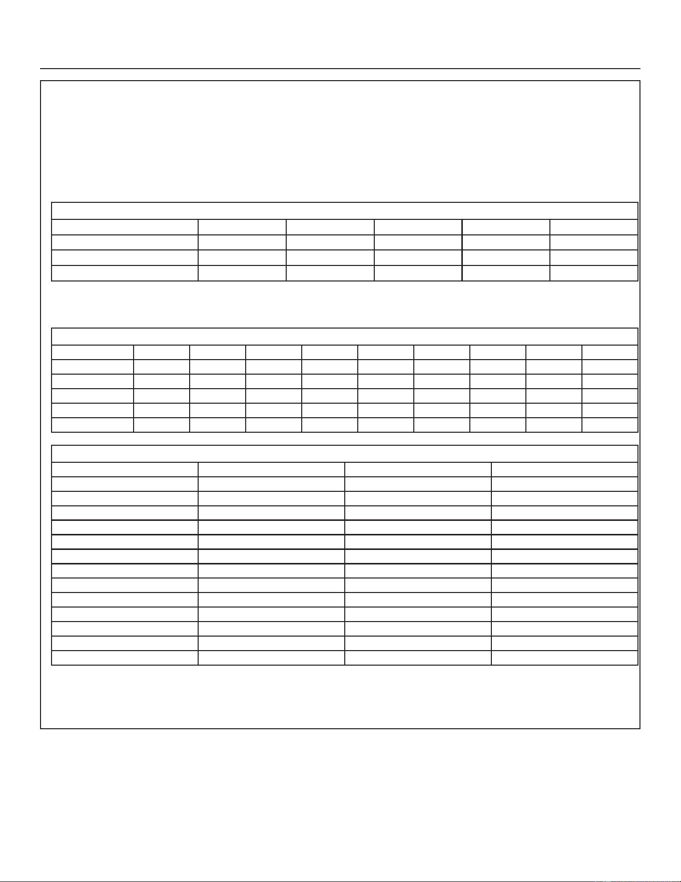
NOTE – R-454B is an A2L refrigerant. The system installation must meet the following parameters based upon total
refrigerant charge (line set included). TAmin (Total minimum conditioned area) is the minimum allowable conditioned
area based upon the total system charge at sea level. Values must be multiplied by altitude adjustment factor at
installed altitude.
Qmin table refers to minimum airflow requirements during refrigerant leak mitigation by the refrigerant detection system,
based upon total system charge.
See tables below.
TAmin Table
Charge (lbs) 10.0 15.0 20.0 25.0 30.0
Charge (kg) 4.5 6.8 9.1 11.3 13.6
Minimum Conditioned Area (ft²) 149.9 224.9 299.9 374.8 449.8
Minimum Conditioned Area (m²) 13.9 20.9 27.9 34.8 41.8
NOTE –7DEOHLVEDVHGRQWKHFRQ¿JXUDWLRQZKHUHWKHGLVFKDUJHSRUWDQGDLUUHWXUQSRUWLQWKHURRPLVKLJKHUWKDQP
NOTE – Multiply values in TAmin table by the Altitude Adjustment Factors to correct TAmin based on installed altitude.
Altitude Adjustment Factor
Altitude (m) 0 200 400 600 800 1000 1200 1400 1600
Altitude (ft) 0 660 1310 1970 2620 3280 3940 4590 5250
Adj. Factor 1 1 1 1 1.02 1.05 1.04 1.1 1.12
Altitude (m) 1600 1800 2000 2200 2400 2600 2800 3000 3200
Altitude (ft) 5250 5910 6560 7220 7870 8530 9190 9840 10500
Adj. Factor 1.12 1.15 1.18 1.21 1.25 1.28 1.32 1.36 1.4
Qmin Table
Refrigerant Charge lb (kg) CFM Required Refrigerant Charge lb (kg) CFM Required
5 (2.268) 135 18 (8.165) 487
6 (2.722) 162 19 (8.618) 514
7 (3.175) 189 20 (9.072) 541
8 (3.629) 216 21 (9.525) 568
9 (4.082) 244 22 (9.979) 595
10 (4.536) 271 23 (10.433) 622
11 (4.990) 298 24 (10.886) 649
12 (5.443) 325 25 (11.340) 676
13 (5.897) 352 26 (11.793) 704
14 (6.350) 379 27 (12.247) 731
15 (6.804) 406 28 (12.701) 758
16 (7.257) 433 29 (13.154) 785
17 (7.711) 460 30 (13.608) 812
NOTE – Qmin minimum airfow requirement for refrigerant leak mitigation.
Installation Instructions
31-5000951 Rev. 0 9
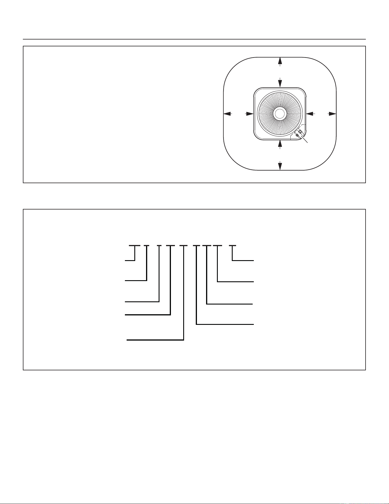
Installation Clearances
NOTES:
• Service clearance of 30” (762 mm) must be maintained
on one of the sides, adjacent to the control box.
• Clearance to one of the other three sides must be 36”
(914 mm).
• Clearance to one of the remaining two sides may be 12”
(305 mm) and the final side may be 6” (152 mm).
• A clearance of 24” (610 mm) must be maintained
between two units.
• 48” (1219 mm) clearance required on top of unit.
Model Number Identification
See
NOTES
See NOTES
See NOTES
See
NOTES
Control
Box
Installation Instructions
MAJOR / MINOR
REVISION
REFRIGERANT
5 - R454B
VOLTAGE
A - 208/230 1PH 60HZ
DESIGN VARIANT
S - SPECIFIED
BRAND
N-GE
PRODUCT
S - SPLIT
SEER
APPLICATION
H - HEAT PUMP
COOLING CAPACITY
(1000BTU/HR)
18, 24, 30, 36, 42, 48, 60
N S A – XX
XX
16
16
H 24
24
S 5
10 31-5000951 Rev. 0
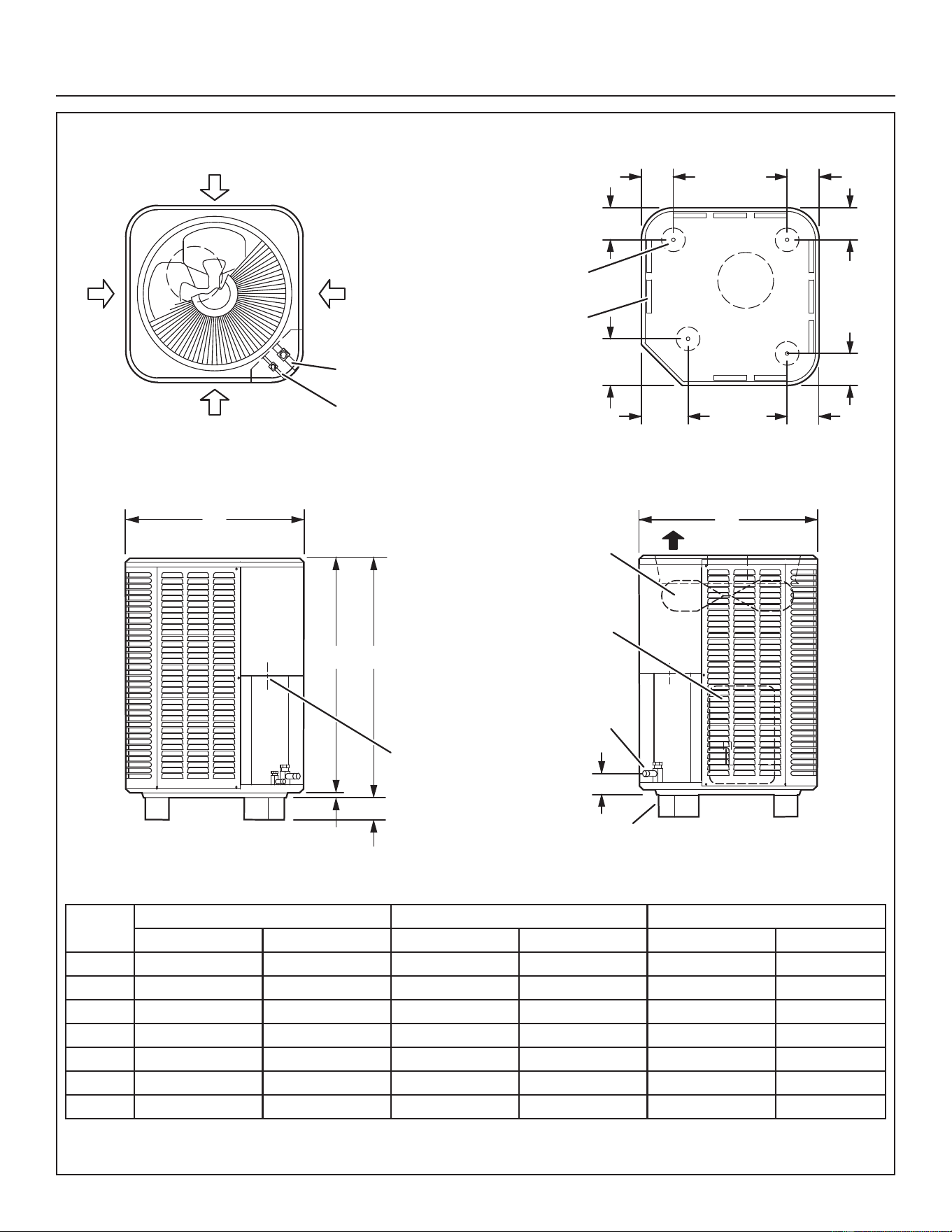
Unit Dimensions
SUCTION AND
C
SIDE VIEW
DISCHARGE AIR
SIDE VIEW
A
B
A
LIQUID LINE
CONNECTION
OUTDOOR
COIL FAN
COMPRESSOR
OPTIONAL UNIT
STANDOFF KIT (4)
(FIELD INSTALLED)
4-3/8
INLET
AIR
INLET
AIR
TOP VIEW
INLET AIR
INLET AIR
SUCTION LINE
CONNECTION
LIQUID LINE
CONNECTION
6-3/8
(162)
TOP VIEW BASE SECTION
COMPRESSOR
COIL DRAIN OUTLETS
(Around perimeter of base)
OPTIONAL UNIT
STAND-OFF KIT (4)
(Field Installed)
(111)
4-3/8
4-3/8
4-3/8
4-3/8
6-3/8
(162)
(111)
(111)
(111
() 111)
4-3/8
(111)
2 (51)
3/4 (19)
2-3/4 (70)
ELECTRICAL
INLETS
Size A B C
In. mm in. mm in. mm
018 28-1/4 718 43-1/4 1099 42-1/2 1080
024 28-1/4 718 43-1/4 1099 42-1/2 1080
030 28-1/4 718 33-1/4 845 32-1/2 826
036 32-1/4 817 33-1/4 845 36-1/2 927
042 32-1/4 817 37-1/4 946 36-1/2 927
048 32-1/4 817 37-1/4 946 28-1/2 724
060 32-1/4 817 37-1/4 946 42-1/2 1080
Installation Instructions
31-5000951 Rev. 0 11
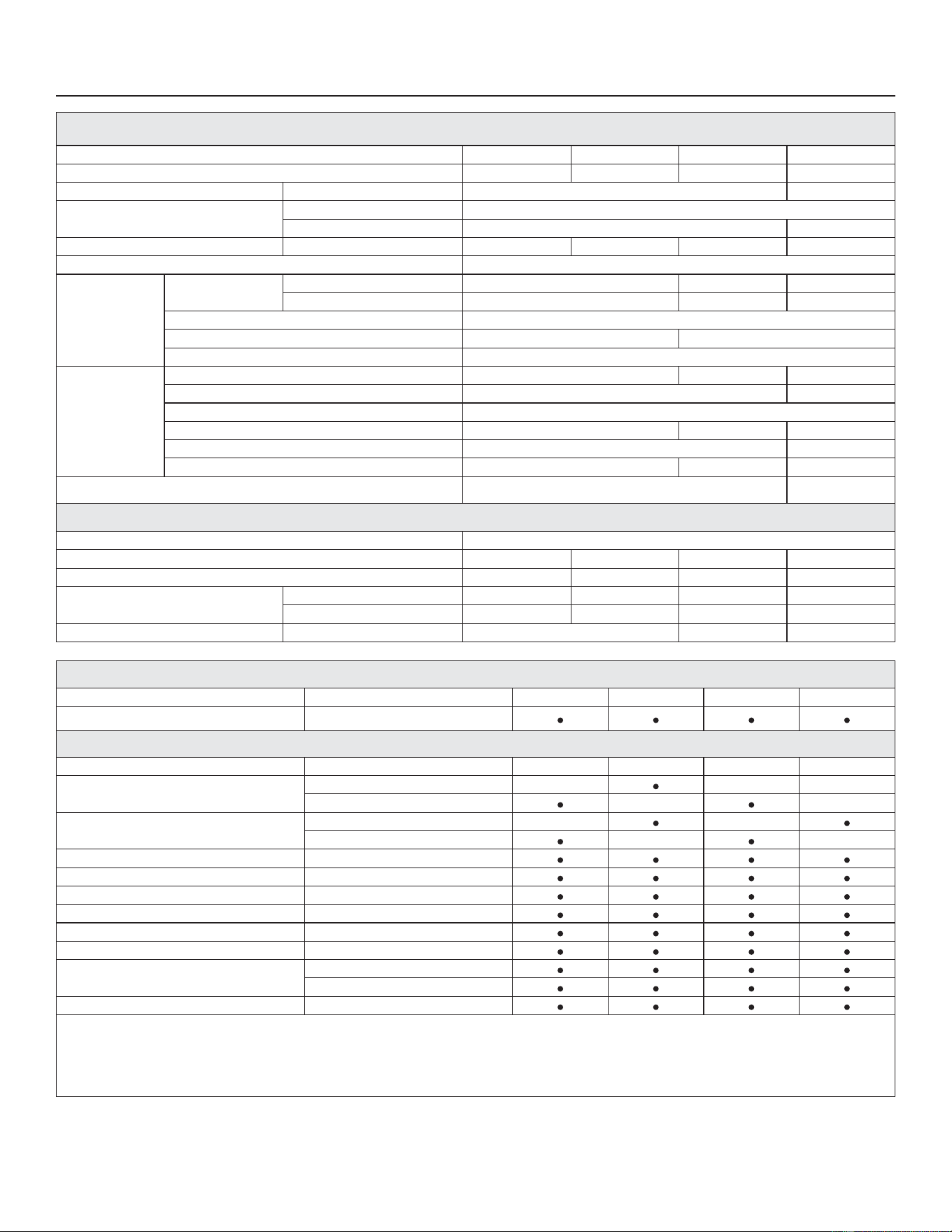
SPECIFICATIONS
Size 018 024 030 036
Nominal Tonnage 1.5 2 2.5 3
Sound Rating Number dBA 74 75
Connections (Sweat)
Liquid line (OD) - in. 3/8
Suction line (OD) - in. 3/4 7/8
Refrigerant Type ¹ R-454B charge furnished 4 lbs. 7 oz. 5 lbs. 3 oz. 6 lbs. 7 oz. 7 lbs. 2 oz.
Indoor Unit Expansion Valve (TXV) 26Z70
Outdoor Coil
Net face area - ft.²
Outer coil 24.5 18.7 22.2
Inner coil - - - 18.0 21.5
Tube diameter - in. 5/16
Rows 1 2
Fins - in 22
Outdoor Fan
HP 1/8 1/6 1/5
Diameter - in. 22 26
Blades 3
Cfm 2840 2670 3590
Rpm 825 839
Watts 127 162 200
Shipping Data - lbs. 185 220
ELECTRICAL DATA
Line voltage data (Volts-Phase-Hz) 208/230-1-60
² Maximum overcurrent protection (MOCP) amps (unit) 15 20 25 35
³ Minimum circuit ampacity (MCA) (unit) 9.7 13.6 16.6 22.2
Compressor
Rated load amps 7.2 10.3 12.5 16.7
Locked rotor amps 47 60.2 67 93.5
Fan Motor Full load amps 0.7 1.0 1.4
OPTIONAL CONTROLS - ORDER SEPARATELY
Accessory Part No. 018 024 030 036
Remote Outdoor Temperature Sensor X2658
OPTIONAL ACCESSORIES - ORDER SEPARATELY
Accessory Part No. 018 024 030 036
Compressor Crankcase Heater
Copeland - 27V63
Factory
LG - 27U16
Factory
Compressor Hard Start Kit
Copeland - 10J42
LG - 88M91
Compressor Sound Cover 18J42
Compressor Low Ambient Cut-Off 45F08
Freezestat - 3/8 in. 93G35
Indoor Blower Off Delay Relay 58M81
/RZ$PELHQW.LW 54M89
Mild Weather Kit 11B97
Outdoor Thermostat Kit
Thermostat - 10Z23
Mounting Box - 31416
Unit Stand-Off Kit 94J45
NOTE - Extremes of operating range are plus 10% and minus 5% of line voltage.
¹ Refrigerant charge is sufficient for 15 ft. length of refrigerant lines. For longer line set requirements see the Installation Instructions for information about line set length and additional refrigerant charge
required.
² HACR type breaker or fuse.
³ Refer to National or Canadian Electrical Code manual to determine wire, fuse and disconnect size requirements.
&UDQNFDVH+HDWHUDQG)UHH]HVWDWDUHUHFRPPHQGHGZLWK/RZ$PELHQW.LW
Installation Instructions
12 31-5000951 Rev. 0
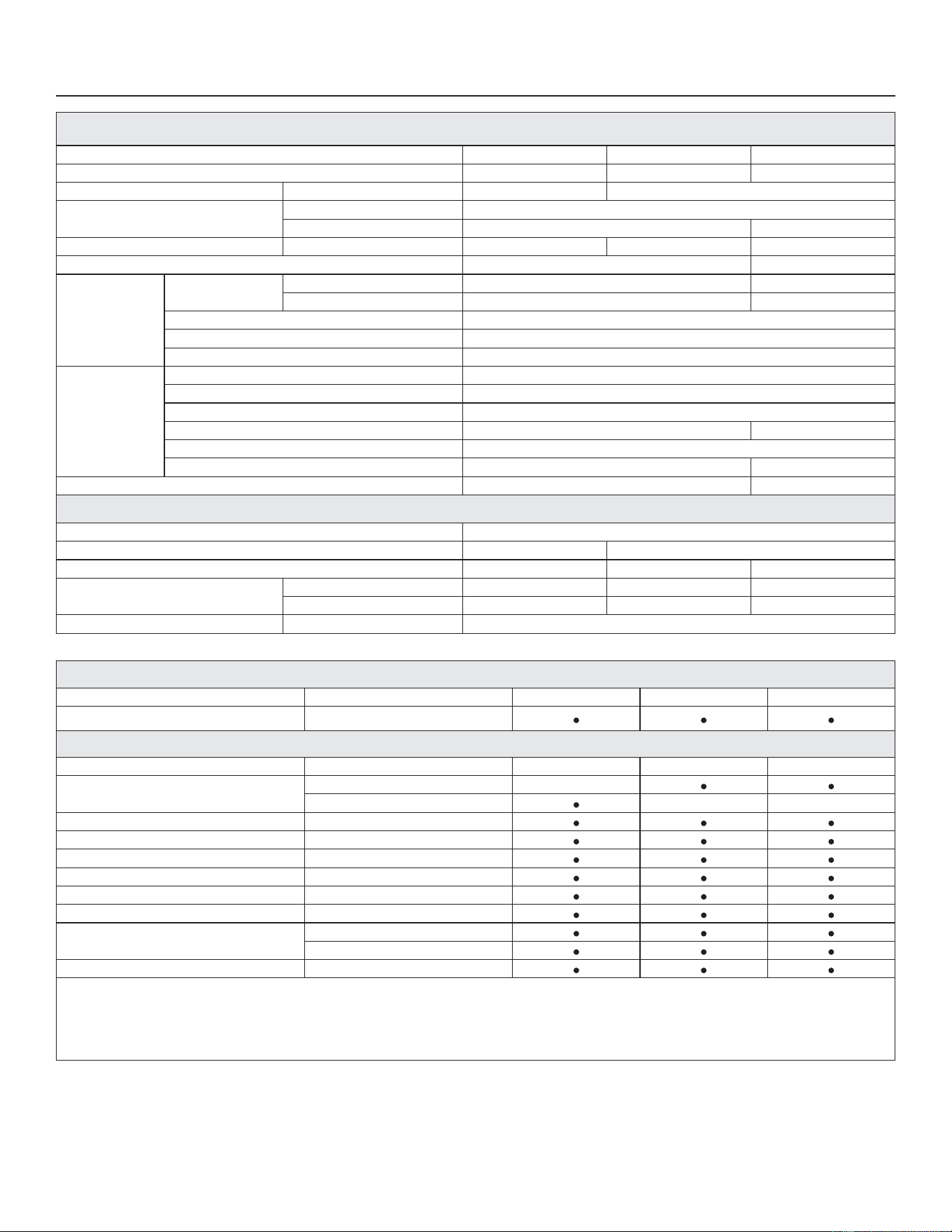
SPECIFICATIONS
Size 042 048 060
Nominal Tonnage 3.5 4 5
Sound Rating Number dBA 78 79
Connections (Sweat)
Liquid line (OD) - in. 3/8
Suction line (OD) - in. 7/8 1-1/8
Refrigerant Type ¹ R-454B charge furnished 8 lbs. 5 oz. 8 lbs. 6 oz. 9 lbs. 6 oz.
Indoor Unit Expansion Valve (TXV) 26Z71 26Z72
Outdoor Coil
Net face area - ft.²
Outer coil 24.93 29.09
Inner coil 24.13 28.16
Tube diameter - in. 5/16
Rows 2
Fins - in 22
Outdoor Fan
HP 1/3
Diameter - in. 26
Blades 4
Cfm 4110 4060
Rpm 825
Watts 213 224
Shipping Data - lbs. 250 260
ELECTRICAL DATA
Line voltage data (Volts-Phase-Hz) 208/230-1-60
² Maximum overcurrent protection (MOCP) amps (unit) 35 50
³ Minimum circuit ampacity (MCA) (unit) 22.3 30.6 32.2
Compressor
Rated load amps 15.8 22.4 23.7
Locked rotor amps 96 126 157
Fan Motor Full load amps 2.6
OPTIONAL CONTROLS - ORDER SEPARATELY
Accessory Part No. 042 048 060
Remote Outdoor Temperature Sensor X2658
OPTIONAL ACCESSORIES - ORDER SEPARATELY
Accessory Part No. 042 048 060
Compressor Hard Start Kit
Copeland - 10J42
LG - 88M91
Compressor Low Ambient Cut-Off 45F08
Compressor Sound Cover 18J42
Freezestat - 3/8 in. 93G35
Indoor Blower Off Delay Relay 58M81
/RZ$PELHQW.LW 54M89
Mild Weather Kit 11B97
Outdoor Thermostat Kit
Thermostat - 10Z23
Mounting Box - 31416
Unit Stand-Off Kit 94J45
NOTE - Extremes of operating range are plus 10% and minus 5% of line voltage.
¹ Refrigerant charge is sufficient for 15 ft. length of refrigerant lines. For longer line set requirements see the Installation Instructions for information about line set length and additional refrigerant charge
required.
² HACR type breaker or fuse.
³ Refer to National or Canadian Electrical Code manual to determine wire, fuse and disconnect size requirements.
&UDQNFDVH+HDWHUDQG)UHH]HVWDWDUHUHFRPPHQGHGZLWK/RZ$PELHQW.LW
Installation Instructions
31-5000951 Rev. 0 13
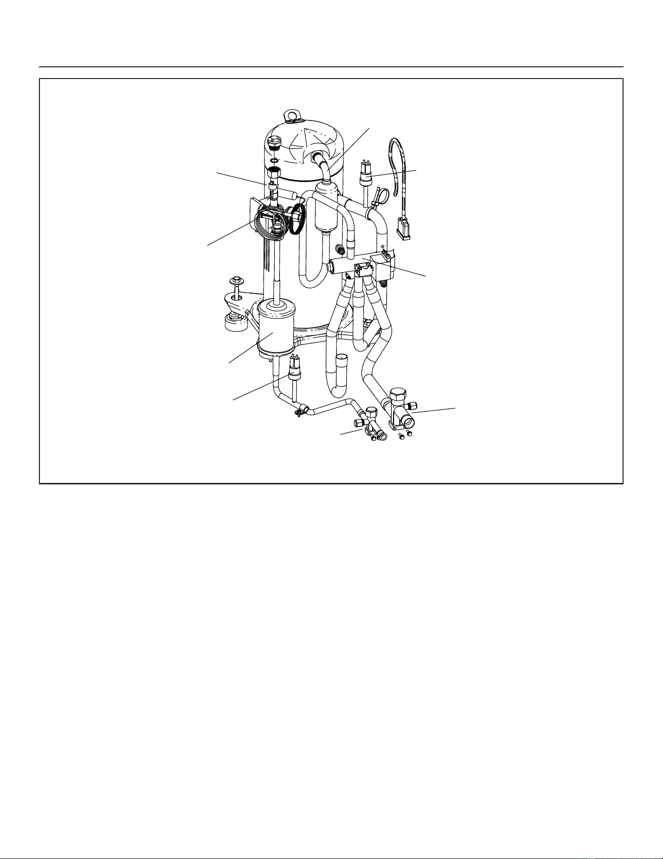
Typical Unit Parts Arrangement
FIGURE 1. Typical Plumbing Arrangement
Discharge Line
Low Pressure Switch
Reversing Valve
High Pressure Switch
Bi-Flow Filter Drier
Check / Expansion Valve
Defrost Coil Sensor
Vapor Line Service Valve
Liquid Line Service Valve
Installation Instructions
14 31-5000951 Rev. 0
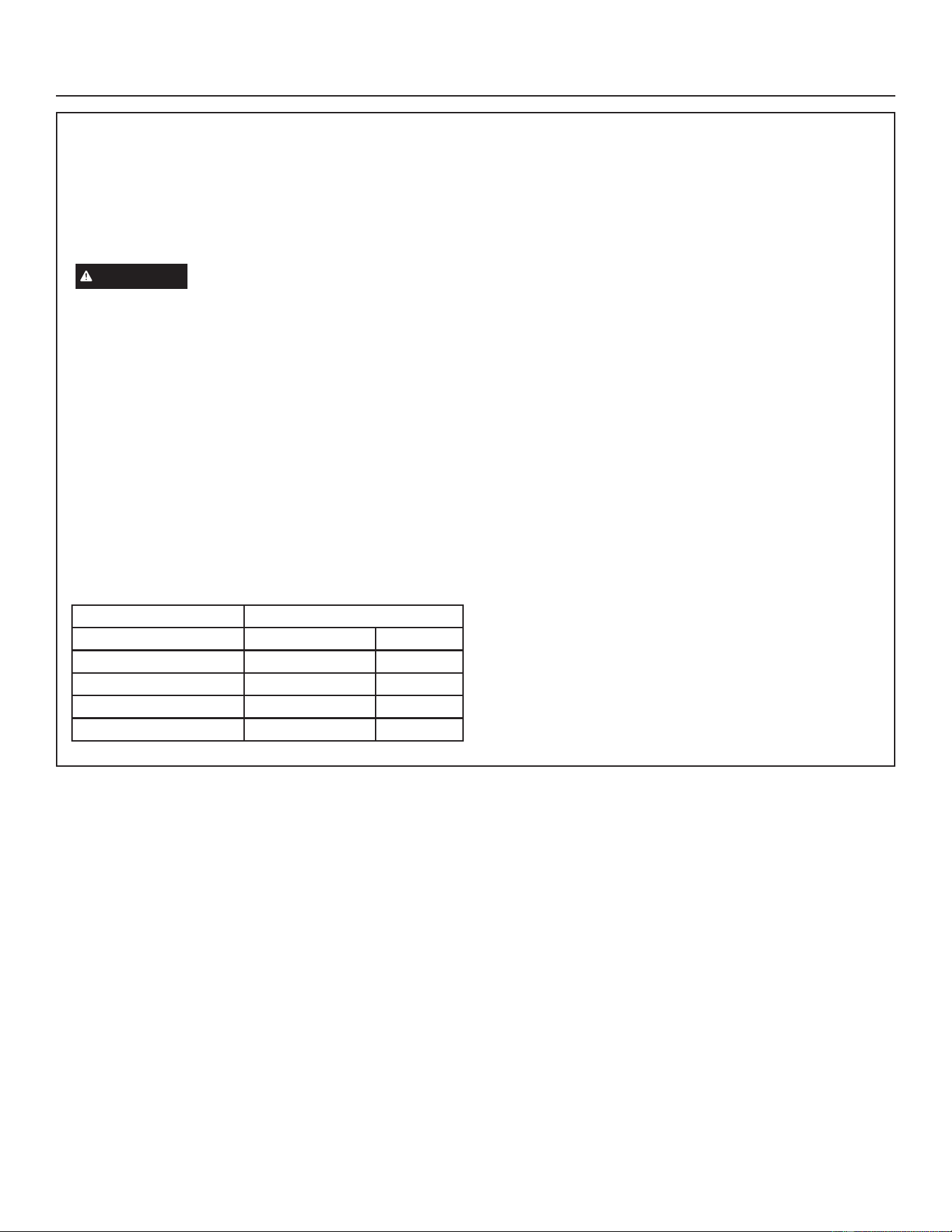
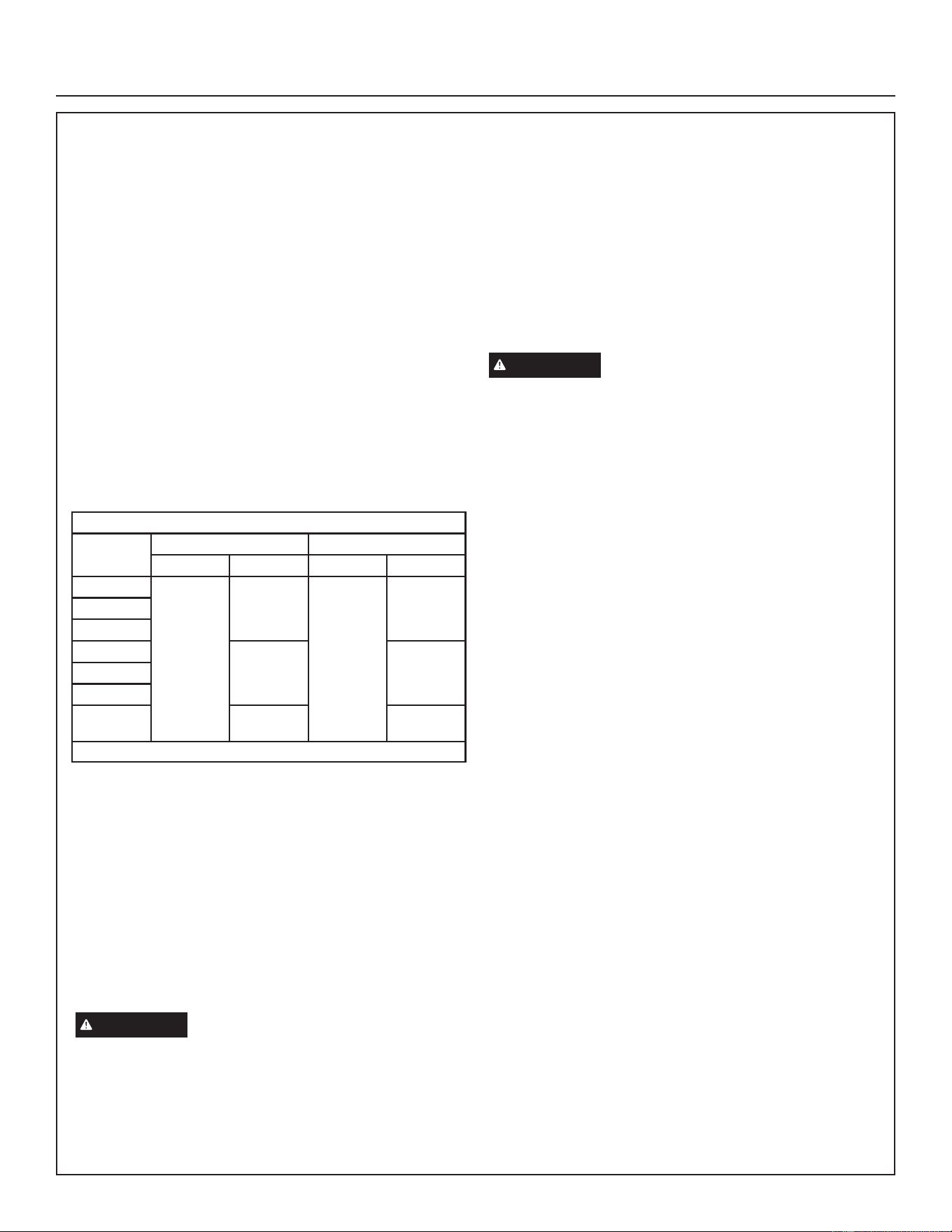
Operating Gauge Set and Service Valves
TORQUE REQUIREMENTS
When servicing or repairing heating, ventilating, and
air conditioning components, ensure the fasteners are
appropriately tightened. Table 1 lists torque values for
fasteners.
IMPORTANT
• Only use Allen wrenches of sufficient hardness (50Rc
- Rockwell Harness Scale minimum). Fully insert the
wrench into the valve stem recess.
• Service valve stems are factory-torqued (from 9 ft-lbs
for small valves, to 25 ft-lbs for large valves) to prevent
refrigerant loss during shipping and handling. Using an
Allen wrench rated at less than 50Rc risks rounding
or breaking off the wrench, or stripping the valve stem
recess.
• See the GE Appliances Service and Application Notes
for further details and information.
• To prevent stripping of the various caps used, the
appropriately sized wrench should be used and fitted
snugly over the cap before tightening.
TABLE 1. Torque Requirements
Parts Recommended Torque
Service valve cap 8 ft.- lb. 11 NM
Sheet metal screws 16 ft.- lb. 2 NM
Machine screws #10 28 ft.- lb. 3 NM
Compressor bolts 90 in.- lb. 10 NM
Gauge port seal cap 8 ft.- lb. 11 NM
USING MANIFOLD GAUGE SET
When checking the system charge, only use a manifold
gauge set that features low loss anti-blow back fittings.
Manifold gauge set used with R-454B refrigerant systems
must be capable of handling the higher system operating
pressures. The gauges should be rated for use with
pressures of 0 - 800 psig on the high side and a low side
of 30” vacuum to 250 psig with dampened speed to 500
psi. Gauge hoses must be rated for use at up to 800 psig
of pressure with a 4000 psig burst rating.
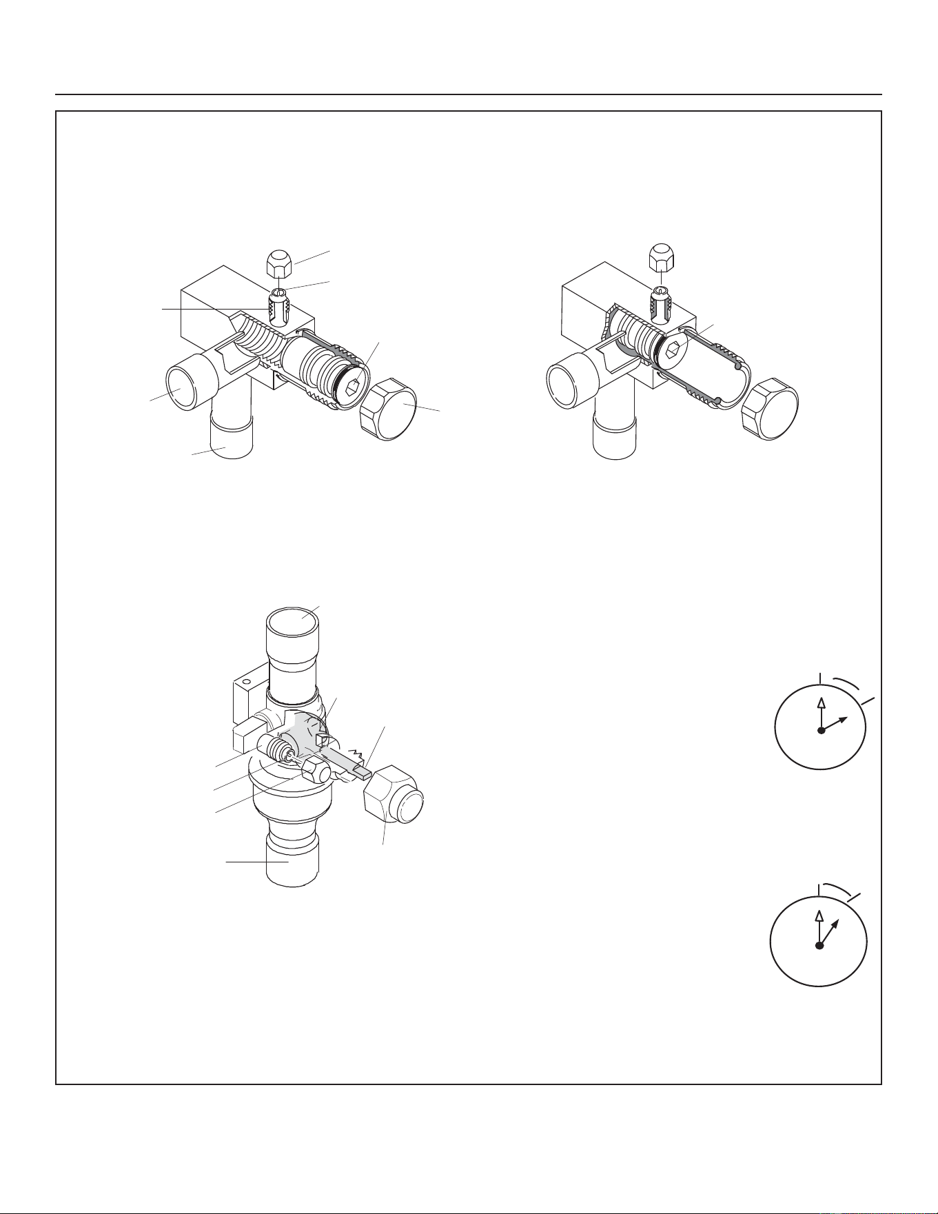
OPERATING SERVICE VALVES
The liquid and vapor line service valves are used for
removing refrigerant, flushing, leak testing, evacuating,
checking charge and charging. Each valve is equipped
with a service port which has a factory-installed valve
stem. Figure 2 provides information on how to access and
operate both angle and ball service valves
Installation Instructions
31-5000951 Rev. 0 15
Service Valves
ANGLE AND BALL
1. Remove stem cap with an appropriately sized wrench.
2. Use a service wrench with a hex-head extension (3/16” for liquid line valve sizes and 5/16” for vapor line valve sizes)
to back the stem out counterclockwise as far as it will go.
Operating Ball Type Service Valve:
1. Remove stem cap with an appropriately sized wrench.
2. Use an appropriately sized wrenched to open. To open
valve, roate stem counterclockwise 90°. To close rotate
stem clockwise 90°.
To Access Service Port:
A service port cap protects the service port core from
contamination and serves as the primary leak seal.
1. Remove service port cap with an appropriately sized
wrench.
2. Connect gauge set to service port.
3. When testing is completed, replace service port cap
and tighten as follows:
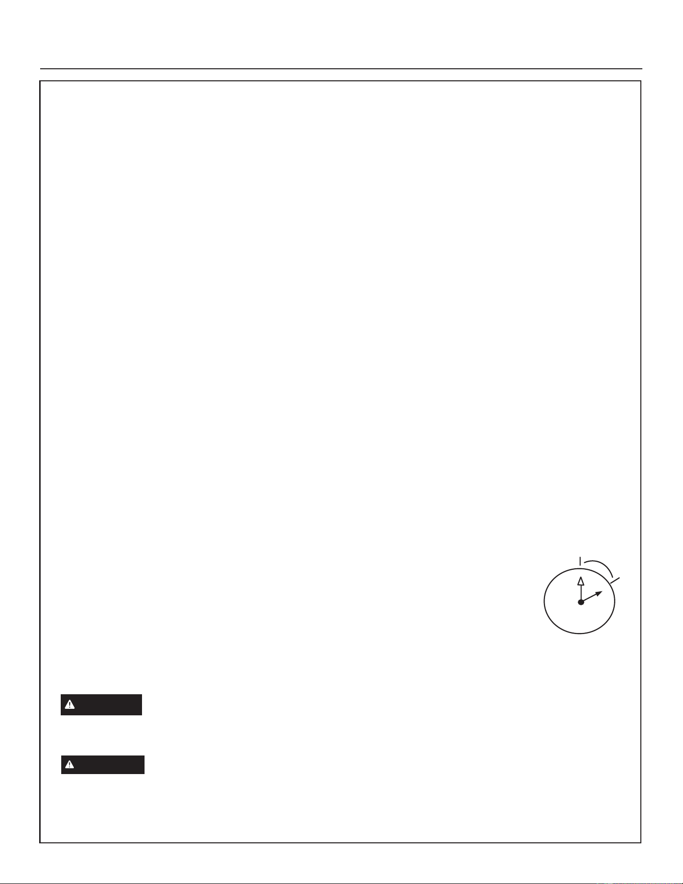
• With torque wrench: Finger tighten
and torque cap per Table 1.
• Without torque wrench: Finger
tighten and use an appropriately
sized wrench to turn an additional 1/6
turn clockwise.
Reinstall Stem Cap:
Stem cap protects the valve stem from damage and serves
as the primary seal. Replace the stem cap and tighten as
follows:
• With Torque Wrench: Finger tighten
and then torque cap per Table 1.
• Without Torque Wrench: Finger
tighten and use an appropriately sized
wrench to turn an additional 1/12 turn
clockwise.
To Indoor Unit
Service Port Core
Service Port Core
To Outdoor Unit
Stem Cap
(Valve Stem Shown Open)
Insert Hex Wrench Here
Service Port Cap
(Valve Stem Shown Closed)
Insert Hex Wrench Here
NOTE — A label with specific torque requirements may be affixed to the stem cap. If the label is present, use the
specified torque.
FIGURE 2. Angle and Ball Service Valves
To OPEN, rotate stem
counterclockwise 90°.
To CLOSE, rotate
stem clockwise 90°.
Service Port Core
Service Port
Service Port Cap
To Outdoor Unit
To Indoor Unit
Stem Cap
Ball (shown
closed)
Valve
Stem
1
2
3
4
5
6
7
8
9
10
11
12
1/6 TURN
1
2
3
4
5
6
7
8
9
10
11
12
1/12 TURN
Installation Instructions
16 31-5000951 Rev. 0
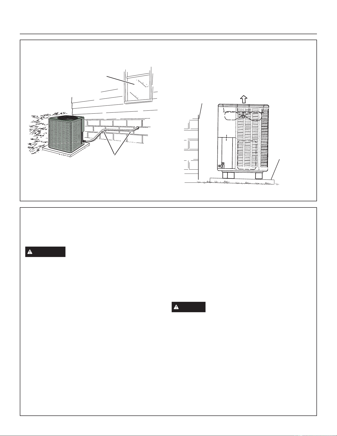
Placement and Slab Mounting
Detail A Detail B
Install unit level or, if on a slope, maintain slope
tolerance of 2 degrees (or 2 inches per 5 feet [50 mm
per 1.5 m]) away from building structure.
Two 90º elbows installed in line
set will reduce line set vibration
Install unit away
from windows
Building
Structure
Discharge Air
Mounting Slab
Ground Level
FIGURE 3. Placement and Slab Mounting
Unit Placement
See Unit Dimensions on Page 10 for sizing mounting
slab, platforms or supports. Refer to Page 9 for mandatory
installation clearance requirements.
CAUTION
In order to avoid injury, take proper
precaution when lifting heavy objects.
POSITIONING CONSIDERATIONS
Consider the following when positioning the unit:
• Some localities are adopting sound ordinances based
on the unit’s sound level registered from the adjacent
property, not from the installation property. Install the unit
as far as possible from the property line.
• When possible, do not install the unit directly outside
a window. Glass has a very high level of sound
transmission.
For proper placement of unit in relation to a window see
the provided illustration in Figure 3, Detail A.
PLACING UNIT ON SLAB
When installing unit at grade level, the top of the slab
should be high enough above grade so that water from
higher ground will not collect around the unit. The slab
should have a slope tolerance as described in Figure 3,
Detail B.
ROOF MOUNTING
Install the unit a minimum of 6 inches (152 mm) above the
roof surface to avoid ice build-up around the unit. Locate
the unit above a load bearing wall or area of the roof that
can adequately support the unit. Consult local codes for
rooftop applications.
If unit coil cannot be mounted away from prevailing winter
winds, a wind barrier should be constructed. Size barrier
at least the same height and width as outdoor unit. Mount
barrier 24 inches (610 mm) from the sides of the unit in the
direction of prevailing winds.
NOTICE
Roof Damage!
This system contains both refrigerant and oil. Some
rubber roofing material may absorb oil, causing the
rubber to swell. Bubbles in the rubber roofing material
can cause leaks. Protect the roof surface to avoid
exposure to refrigerant and oil during service and
installation. Failure to follow this notice could result in
damage to roof surface.
Installation Instructions
31-5000951 Rev. 0 17
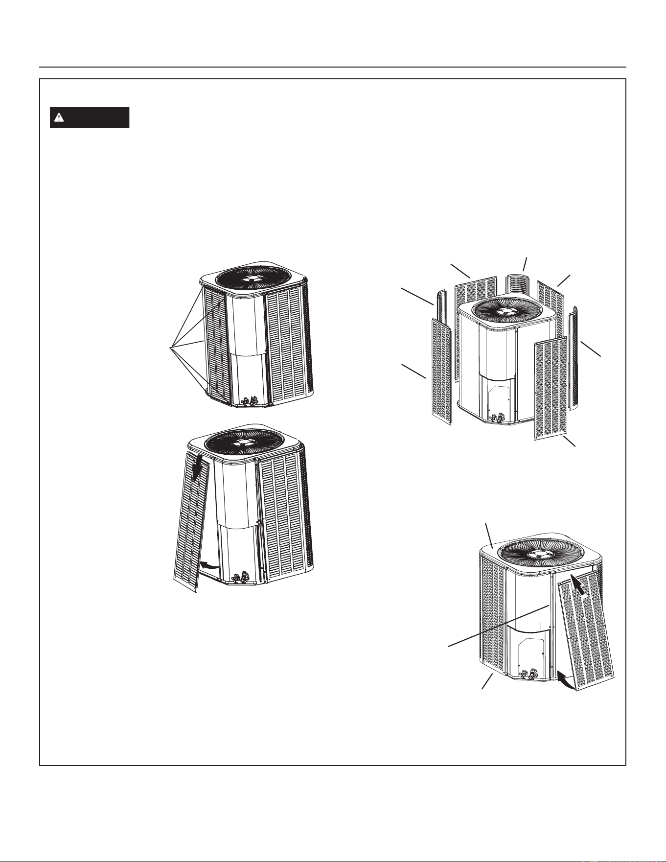
Removing and Installing Louvered Panels
WARNING
To prevent personal injury, or damage to panels, unit or structure, be sure to observe the following:
• While installing or servicing this unit, carefully stow all removed panels out of the way, so that the panels will not cause
injury to personnel, nor cause damage to objects or structures nearby, nor will the panels be subjected to damage
(e.g., being bent or scratched).
• While handling or stowing the panels, consider any weather conditions, especially windy conditions, that may cause
panels to be blown around and battered.
STEP 1
To remove panel,
remove mounting
screws securing panel
to the unit.
STEP 2
Slightly lift panel in
order to clear side lips
of panel from base of
unit.
STEP 3
Tilt panel out slightly
and pull downward to
remove.
STEP 1
Insert panel under unit top cap lip and lift slightly to clear
side lip of panel from base.
STEP 2
Move panel in
towards unit. Align
left/right side lips of
panel with groove
inserts along left/
right side of unit.
STEP 3
Secure panel, with
mounting screws.
PANEL INSTALLATION
Panel Center
Panel Center
Corner Post
Corner Post
Panel Left
Panel Right
Corner
Post
Top Cap
Side
Groove
Base
REMOVAL
FIGURE 4. Louvered Panels
Installation Instructions
18 31-5000951 Rev. 0
New or Replacement Line Set
This section provides information on new installation or
replacement of existing line set. If a new or replacement
line set is not required, then proceed to Brazing
Connections on Page 20.
If refrigerant lines are routed through a wall, seal and
isolate the opening so vibration is not transmitted to the
building. Pay close attention to line set isolation during
installation of any HVAC system. When properly isolated
from building structures (walls, ceilings. floors), the
refrigerant lines will not create unnecessary vibration and
subsequent sounds.
REFRIGERANT LINE SET
Field refrigerant piping consists of liquid and suction lines
from the outdoor unit (braze connections) to the indoor
unit coil (flare or braze connections).
TABLE 2
REFRIGERANT LINE SET – INCHES (MM)
Model
Valve Field Connections Recommended Line Set
Liquid Line Vapor Line Liquid Line Vapor Line
– 018
3/8”
(10mm)
3/4”
(19mm)
3/8”
(10mm)
3/4”
(19mm)
– 024
– 030
– 036
7/8”
(22mm)
7/8”
(22mm)
– 042
– 048
– 060
1-1/8”
(28mm)
1-1/8”
(28mm)
NOTE - Some applications may require a field-provided 7/8” to 1-1/8” adapter.
NOTE – When installing refrigerant lines longer than 50
feet, contact GE Appliances Technical Support Product
Applications for assistance or GE Appliances piping
manual. To obtain the correct information from GE
Appliances, be sure to communicate the following points:
• Model NS16H and size of unit (e.g. -060).
• Line set diameters for the unit being installed as listed in
table 2 and total length of installation.
• Number of elbows and if there is a rise or drop of the
piping.
IMPORTANT
Mineral oils are not compatible with R-454B. If oil must be
added, it must be a Polyol ester oil.
The compressor is charged with sufficient Polyol ester oil
for line set lengths up to 50 feet. Recommend adding oil to
system based on the amount of refrigerant charge in the
system. No need to add oil in system with 20 pounds of
refrigerant or less. For systems over 20 pounds - add one
ounce for every five pounds of refrigerant.
Recommended topping-off POE oils are Mobil EAL
$5&7,&&&RU,&,(0.$5$7(5/&)
LINE SET ISOLATION
IMPORTANT
If this unit is being matched with an approved line set
or indoor unit coil that was previously charged with
mineral oil, or if it is being matched with a coil which was
manufactured before January of 1999, the coil and line
set must be flushed prior to installation. Take care to
empty all existing traps. Polyol ester (POE) oils are used
in GE Appliances units charged with R-454B refrigerant.
Residual mineral oil can act as an insulator, preventing
proper heat transfer. It can also clog the expansion device
and reduce system performance and capacity. Failure
to properly flush the system, per this instruction and the
detailed Installation and Service Procedures manual will
void the warranty.
Installation Instructions
31-5000951 Rev. 0 19
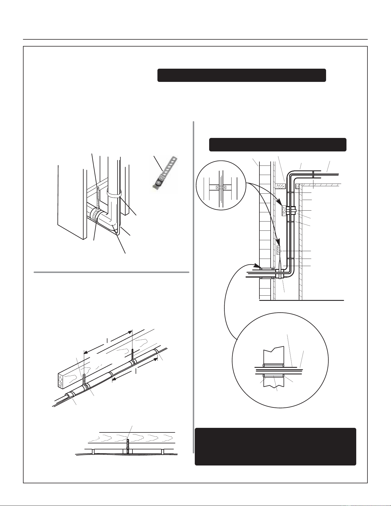
ANCHORED HEAVY NYLON
WIRE TIE OR AUTOMOTIVE
MUFFLER‐TYPE HANGER
STRAP LIQUID LINE TO
VAPOR LINE
WALL
STUD
LIQUID LINE
NON-CORROSIVE
METAL SLEEVE
VAPOR LINE - WRAPPED
IN ARMAFLEX
AUTOMOTIVE
MUFFLER‐TYPE HANGER
REFRIGERANT LINE SET — TRANSITION
FROM VERTICAL TO HORIZONTAL
Line Set Isolation — The following illustrations are
examples of proper refrigerant line set isolation:
STRAPPING
MATERIAL (AROUND
VAPOR LINE ONLY)
TAPE OR
WIRE TIE
WIRE TIE (AROUND
VAPOR LINE ONLY)
FLOOR JOIST OR
ROOF RAFTER
TAPE OR
WIRE TIE
To hang line set from joist or rafter, use either metal strapping material
or anchored heavy nylon wire ties.
8 FEET (2.43 METERS)
STRAP THE VAPOR LINE TO THE JOIST
OR RAFTER AT 8 FEET (2.43 METERS)
INTERVALS THEN STRAP THE LIQUID
LINE TO THE VAPOR LINE.
FLOOR JOIST OR
ROOF RAFTER
REFRIGERANT LINE SET — INSTALLING
HORIZONTAL RUNS
NOTE — Similar installation practices should be used if line set is
to be installed on exterior of outside wall.
PVC
PIPE
FIBERGLASS
INSULATION
CAULK
OUTSIDE
WALL
VAPOR LINE WRAPPED
WITH ARMAFLEX
LIQUID
LINE
OUTSIDE WALL
LIQUID LINE
VAPOR LINE
WOOD BLOCK
BETWEEN STUDS
STRAP
WOOD BLOCK
STRAP
SLEEVE
WIRE TIE
WIRE TIE
WIRE TIE
INSIDE WALL
REFRIGERANT LINE SET — INSTALLING
VERTICAL RUNS (NEW CONSTRUCTION SHOWN)
INSTALLATION
LINE SET
NOTE — Insulate liquid line when it is routed through areas where the
surrounding ambient temperature could become higher than the
temperature of the liquid line or when pressure drop is equal to or greater
than 20 psig.
NON-CORROSIVE
METAL SLEEVE
IMPORTANT — Refrigerant lines must not contact structure.
NON-CORROSIVE
METAL SLEEVE
8 FEET (2.43 METERS)
IMPORTANT — Refrigerant lines must not contact wall
WARNING — Polyol ester (POE) oils used with R-454B
refrigerant absorb moisture veryquickly. Itis very important thatthe
refrigerant system be kept closed as much as possible. DO NOT
remove line set caps or service valve stub caps until you are ready
to make connections.
FIGURE 5. Line Set Installation
Installation Instructions
20 31-5000951 Rev. 0
Brazing Connections
Use the procedures outlined in Figure 6 and Figure 7 for brazing line set connections to service valves.
WARNING
Danger of fire. Bleeding the refrigerant
charge from only the high side may result
in pressurization of the low side shell and
suction tubing. Application of a brazing torch
to a pressurized system may result in ignition
of the refrigerant and oil mixture. Check the
high and low pressures before applying heat.
WARNING
When using a high pressure gas such as
nitrogen to pressurize a refrigeration or air
conditioning system, use a regulator that can
control the pressure down to 1 or 2 psig (6.9
to 13.8 kPa).
CAUTION
• Brazing alloys and flux contain materials which are
hazardous to your health.
• Avoid breathing vapors or fumes from brazing operations.
Perform operations only in well-ventilated areas.
• Wear gloves and protective goggles or face shield to
protect against burns.
• Wash hands with soap and water after handling brazing
alloys and flux.
IMPORTANT
• Allow braze joint to cool before removing the wet rag
from the service valve. Temperatures above 250ºF can
damage valve seals.
• Use silver alloy brazing rods with 5% minimum silver
alloy for copper-to-copper brazing. Use 45% minimum
alloy for copper-to-brass and copper-to-steel brazing.
WARNING
Fire, Explosion and Personal Safety hazard.
Failure to follow this warning could result in
damage, personal injury or death.
Never use oxygen to pressurize or purge
refrigeration lines. Oxygen, when exposed to
a spark or open flame, can cause fire and/
or an explosion, that could result in property
damage, personal injury or death.
Installation Instructions
31-5000951 Rev. 0 21
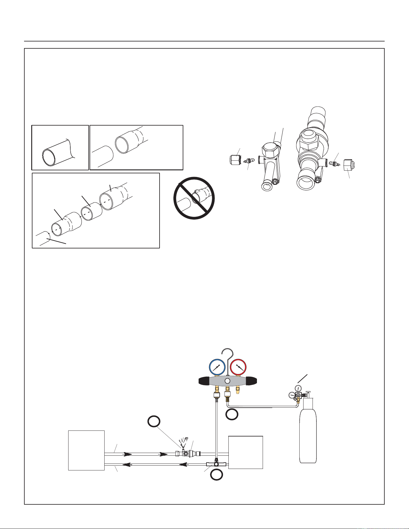
Brazing Procedures
1. CUT AND DEBUR
Cut ends of the refrigerant lines square (free from nicks
or dents) and debur the ends. The pipe must remain
round. Do not crimp end of the line.
2. CAP AND CORE REMOVAL
Remove service cap and core from both the suction /
vapor and liquid line service ports.
LIQUID LINE SERVICE
VALVE
SERVICE
PORT
CORE
SERVICE PORT
CAP
SERVICE
PORT
CORE
SERVICE
PORT CAP
CUT AND DEBUR
LINE SET SIZE MATCHES
SERVICE VALVE CONNECTION
COPPER TUBE
STUB
SERVICE VALVE
CONNECTION
REFRIGERANT LINE
DO NOT CRIMP SERVICE VALVE
CONNECTOR WHEN PIPE IS
SMALLER THAN CONNECTION
REDUCER
SUCTION / VAPOR LINE
SERVICE VALVE
LINE SET SIZE IS SMALLER
THAN CONNECTION
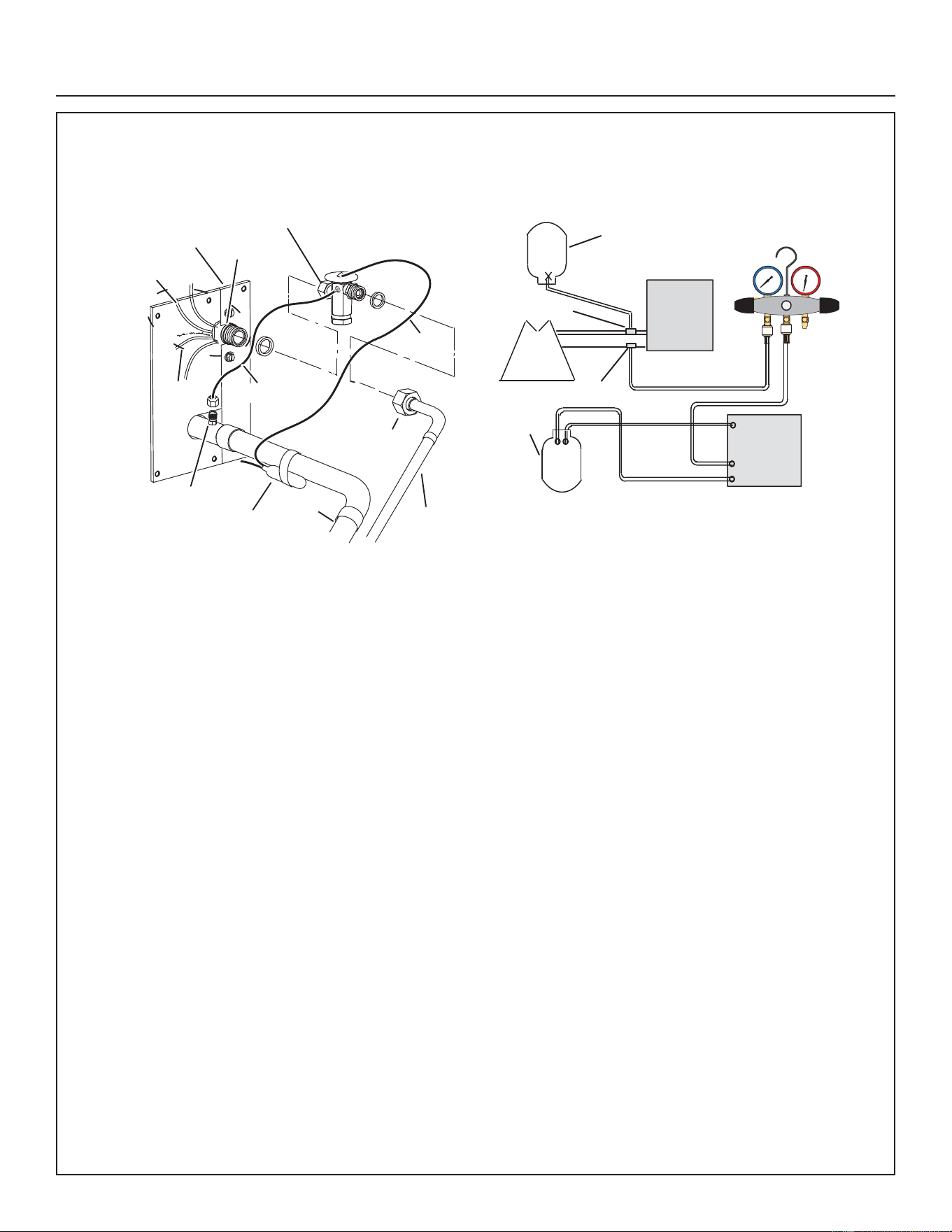
3. ATTACH THE MANIFOLD GAUGE SET FOR BRAZING LIQUID AND SUCTION / VAPOR LINE SERVICE VALVES
Flow regulated nitrogen (at 1 to 2 psig) through the low-side refrigeration gauge set into the liquid line service port valve,
and out of the suction / vapor line service port valve.
A. Connect gauge set low pressure side to liquid line service valve (service port).
B. Connect gauge set center port to bottle of nitrogen with regulator.
C. Remove core from valve in suction / vapor line service port to allow nitrogen to escape
OUTDOOR
UNIT
LIQUID LINE
VAPOR LINE
LIQUID LINE SERVICE
VALVE
SUCTION /
VAPOR LINE
SERVICE
VALVE
ATTACH
GAUGES
INDOOR
UNIT
SUCTION / VAPOR SERVICE PORT MUST BE
OPEN TO ALLOW EXIT POINT FOR NITROGEN
NITROGEN
HIGHLOW
USE REGULATOR TO FLOW
NITROGEN AT 1 TO 2 PSIG.
B
A
C
WHEN BRAZING LINE SET TO
SERVICE VALVES, POINT FLAME
AWAY FROM SERVICE VALVE.
Installation Instructions
22 31-5000951 Rev. 0
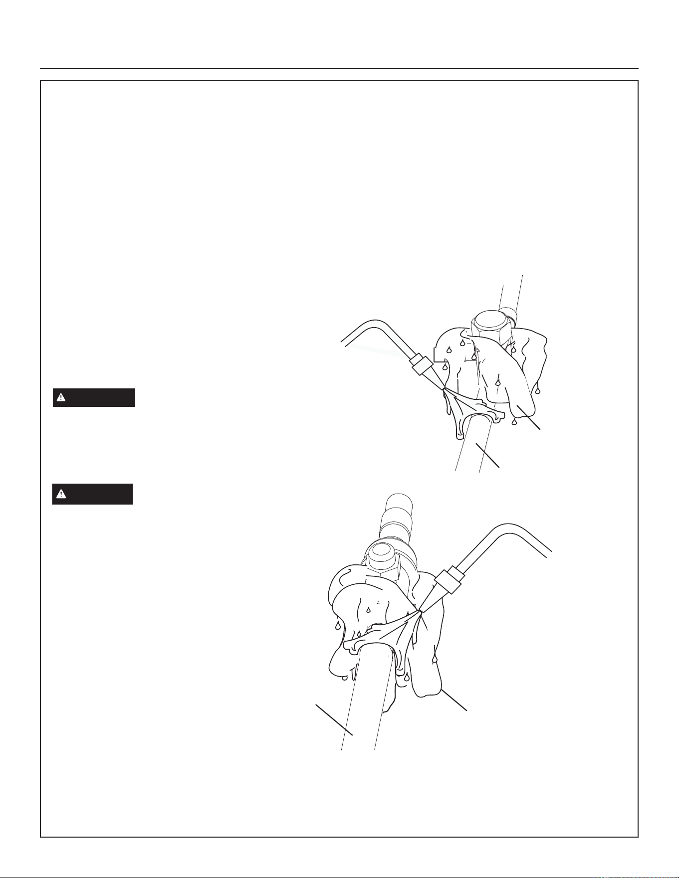
Brazing Procedures (cont.)
4. WRAP SERVICE VALVES
To help protect service valve seals during brazing, wrap water saturated cloths around service valve bodies and copper
tube stubs. Use additional water saturated cloths underneath the valve body to protect the base paint.
5. FLOW NITROGEN
Flow regulated nitrogen (at 1 to 2 psig) through the refrigeration gauge set into the valve stem port connection on the
liquid service valve and out of the suction / vapor valve stem port. See steps 3A, 3B and 3C on manifold gauge set
connections.
6. BRAZE LINE SET
Wrap both service valves with water saturated cloths as illustrated here and as mentioned in step 4, before brazing to
line set. Water saturated cloths must remain water saturated throughout the brazing and cool-down process.
7. PREPARATION FOR NEXT STEP
After all connections have been brazed, disconnect manifold gauge set from service ports. Apply additional water
saturated cloths to both services valves to cool piping. Once piping is cool, remove all water saturated cloths. Refer to
the unit installation instructions for the next step in preparing the unit.
WHEN BRAZING LINE SET TO
SERVICE VALVES, POINT FLAME
AWAY FROM SERVICE VALVE.
LIQUID LINE SERVICE VALVE
LIQUID LINE
WATER-SATURATED
CLOTH
SUCTION LINE
WATER-SATURATED
CLOTH
SUCTION LINE SERVICE
VALVE
WHEN BRAZING LINE SET TO
SERVICE VALVES, POINT FLAME
AWAY FROM SERVICE VALVE.
IMPORTANT
Allow braze joint to cool. Apply
additional water saturated cloths to help cool brazed
joint. Do not remove water saturated cloths until piping
has cooled. Temperatures above 250ºF will damage
valve seals.
WARNING
1. FIRE, PERSONAL INJURY, OR
PROPERTY DAMAGE may result
if you do not wrap a water saturated
cloth around both liquid and suction
line service valve bodies and copper
tube stub while brazing in the line set!
The braze, when complete, must be
quenched with water to absorb any
residual heat.
2. Do not open service valves until
refrigerant lines and indoor coil have
been leak-tested and evacuated.
Refer to procedures provided in this
supplement.
Installation Instructions
31-5000951 Rev. 0 23
Flushing Line Set and Indoor Coil
1. TYPICAL EXISTING EXPANSION VALVE REMOVAL
PROCEDURE (UNCASED COIL SHOWN)
SENSING
LINE
TWO PIECE PATCH PLATE
(UNCASED COIL ONLY)
VAPOR
LINE
DISTRIBUTOR
ASSEMBLY
DISTRIBUTOR
TUBES
LIQUID
LINE
MALE EQUALIZER
LINE FITTING
EQUALIZER
LINE
CHECK
EXPANSION
VALVE
TEFLON
®
RING
STUB END
TEFLON
®
RING
SENSING BULB
LIQUID LINE
ORIFICE
HOUSING
LIQUID LINE
ASSEMBLY WITH
BRASS NUT
A. On fully cased coils, remove the coil access and
plumbing panels.
B. Remove any shipping clamps holding the liquid line and
distributor assembly.
C. Disconnect the equalizer line from the check expansion
valve equalizer line fitting on the vapor line.
D. Remove the vapor line sensing bulb.
E. Disconnect the liquid line from the check expansion
valve at the liquid line assembly.
F. Disconnect the check expansion valve from the liquid
line orifice housing. Take care not to twist or damage
distributor tubes during this process.
G. Remove and discard check expansion valve and the
two Teflon
®
rings.
H. Use a field-provided fitting to temporary reconnect the
liquid line to the indoor unit’s liquid line orifice housing.
2. CONNECT GAUGES AND EQUIPMENT FOR
FLUSHING PROCEDURE
LOW HIGH
EXISTING
INDOOR
UNIT
GAUGE
MANIFOLD
INVERTED CYLINDER
CONTAINS CLEAN
HCFC22* TO BE USED
FOR FLUSHING.
LIQUID LINE SERVICE
VALVE
INLET
DISCHARGE
TANK
RETURN
CLOSED
OPENED
RECOVERY CYLINDER
RECOVERY MACHINE
NEW
OUTDOOR
UNIT
VAPOR LINE
SERVICE VALVE
VAPOR
LIQUID
1
A
B
C
D
A. Inverted HCFC-22 cylinder with clean refrigerant* to the
vapor service valve.
B. HCFC-22 gauge set (low side) to the liquid line valve.
C. HCFC-22 gauge set center port to inlet on the recovery
machine with an empty recovery tank to the gauge set.
D. Connect recovery tank to recovery machines per
machine instructions.
3. FLUSHING LINE SET
The line set and indoor unit coil must be flushed with at
least the same amount of clean refrigerant* that previously
charged the system. Check the charge in the flushing
cylinder before proceeding.
A. Set the recovery machine for liquid recovery and start
the recovery machine. Open the gauge set valves to
allow the recovery machine to pull a vacuum on the
existing system line set and indoor unit coil.
B. Invert the cylinder of clean HCFC-22* and open its
valve to allow liquid refrigerant to flow into the system
through the vapor line valve. Allow the refrigerant to
pass from the cylinder and through the line set and the
indoor unit coil before it enters the recovery machine.
C. After all of the liquid refrigerant has been recovered,
switch the recovery machine to vapor recovery so
that all of the HCFC-22 vapor is recovered. Allow the
recovery machine to pull the system down to 0.
D. Close the valve on the inverted HCFC-22 drum and the
gauge set valves. Pump the remaining refrigerant out
of the recovery machine and turn the machine off.
*IMPORTANT - Clean refrigerant is any refrigerant in a system that has not had compressor burn out. If the system has
experienced burn out, it is recommended that the existing line set and indoor coil be replaced.
Installation Instructions
24 31-5000951 Rev. 0
Installing Indoor Metering Device
This outdoor unit is designed for use in systems that use a
check / expansion valve metering device at the indoor coil.
See the NS16H Product Specification bulletin for approved
expansion valve kit match-ups. The expansion valve unit
can be installed internal or external to the indoor coil. In
applications where an uncased coil is being installed in
a field-provided plenum, install the expansion valve in a
manner that will provide access for field servicing of the
expansion valve. Refer to below illustration for reference
during installation of expansion valve unit.
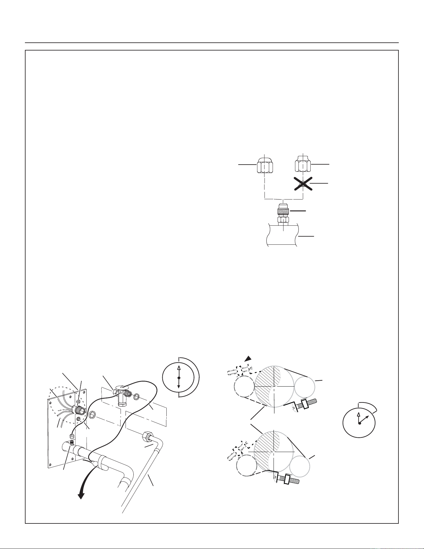
INDOOR EXPANSION VALVE INSTALLATION
A. Remove the field-provided fitting that temporary
reconnected the liquid line to the indoor unit’s distributor
assembly.
B. Install one of the provided Teflon® rings around the
stubbed end of the expansion valve and lightly lubricate
the connector threads and expose surface of the
Teflon® ring with refrigerant oil.
C. Attach the stubbed end of the expansion valve to the
liquid line orifice housing. Finger tighten and use an
appropriately sized wrench to turn an additional 1/2 turn
clockwise as illustrated in the figure above, or 20 ft-lb.
D. Place the remaining Teflon® washer around the other
end of the expansion valve. Lightly lubricate connector
threads and expose surface of the Teflon® ring with
refrigerant oil.
E. Attach the liquid line assembly to the expansion valve.
Finger tighten and use an appropriately sized wrench to
turn an additional 1/2 turn clockwise or 20 ft-lb.
EQUALIZER LINE INSTALLATION
A. Remove and discard either the flare seal cap or flare
nut with copper flare seal bonnet from the equalizer line
port on the vapor line as illustrated in the figure to the
right.
B. Remove and discard either the flare seal cap or flare
nut with copper flare seal bonnet from the equalizer line
port on the vapor line as illustrated in the figure to the
right.
VAPOR
LINE
FLARE
NUT
COPPER FLARE
SEAL BONNET
MALE BRASS
EQUALIZER
LINE FITTING
FLARE
SEAL CAP
OR
SENSING BULB INSTALLATION
A. Attach the vapor line sensing bulb in the proper
orientation as illustrated to the right using the clamp
and screws provided.
NOTE — Confirm proper thermal contact between vapor
line and expansion bulb before insulating the sensing bulb
once installed.
B. Connect the equalizer line from the expansion valve
to the equalizer vapor port on the vapor line. Finger
tighten the flare nut plus 1/8 turn (7 ft-lbs) as illustrated
below.
ON 7/8” AND LARGER LINES,
MOUNT SENSING BULB AT
EITHER THE 4 OR 8 O'CLOCK
POSITION. NEVER MOUNT ON
BOTTOM OF LINE.
12
ON LINES SMALLER THAN
7/8”, MOUNT SENSING
BULB BETWEEN THE 3 AND
9 O'CLOCK POSITIONS.
12
BULB
VAPOR LINE
NOTE — NEVER MOUNT ON BOTTOM OF LINE.
BULB
BULB
BULB
3 O'CLOCK
TWO PIECE
PATCH PLATE
(UNCASED
COIL ONLY)
VAPOR
LINE
LIQUID LINE
ORIFICE
HOUSING
DISTRIBUTOR
TUBES
LIQUID LINE
MALE EQUALIZER LINE
FITTING (SEE
EQUALIZER LINE
INSTALLATION FOR
FURTHER DETAILS)
SENSING
LINE
EQUALIZER
LINE
EXPANSION
VALVE
TEFLON
®
RING
(Uncased Coil Shown)
Sensing bulb insulation is required if
mounted external to the coil casing. See
sensing bulb installation for bulb positioning.
STUB
END
TEFLON
®
RING
LIQUID LINE
ASSEMBLY WITH
BRASS NUT
DISTRIBUTOR
ASSEMBLY
1
2
3
4
5
6
7
8
9
10
11
12
1/2 Turn
1
2
3
4
5
6
7
8
9
10
11
12
1/8 Turn
Installation Instructions
31-5000951 Rev. 0 25
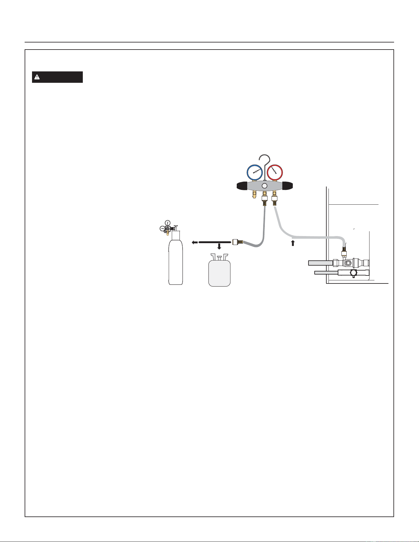
Leak Test Line Set and Indoor Coil
IMPORTANT
Leak detector must be capable of sensing HFC refrigerant.
1. CONNECT GAUGE SET
A. Connect an R-454B manifold gauge set high pressure hose to the vapor valve service port.
NOTE — Normally, the high pressure hose is connected to the liquid line port. However, connecting it to the vapor port
better protects the manifold gauge set from high pressure damage.
B. With both manifold valves closed,
connect the cylinder of R-454B
refrigerant to the center port of the
manifold gauge set.
NOTE — Later in the procedure, the
R-454B container will be replaced by the
nitrogen container.
2. TEST FOR LEAKS
After the line set has been connected to the indoor and outdoor units, check the line set connections and indoor unit for
leaks. Use the following procedure to test for leaks:
A. With both manifold valves closed, connect the cylinder of R-454B refrigerant to the center port of the manifold gauge
set. Open the valve on the R-454B cylinder (vapor only).
B. Open the high pressure side of the manifold to allow R-454B into the line set and indoor unit. Weigh in a trace amount
of R-454B. [A trace amount is a maximum of two ounces (57 g) refrigerant or three pounds (31 kPa) pressure]. Close
the valve on the R-454B cylinder and the valve on the high pressure side of the manifold gauge set. Disconnect the
R-454B cylinder.
C. Connect a cylinder of dry nitrogen with a pressure regulating valve to the center port of the manifold gauge set.
D. Adjust dry nitrogen pressure to 160 psig (1103 kPa). Open the valve on the high side of the manifold gauge set in
order to pressurize the line set and the indoor unit.
E. After a few minutes, open one of the service valve ports and verify that the refrigerant added to the system earlier
is measurable with a leak detector Once leak detector is confirmed operational, leak check the entire system (field
joints and line set included) to a sensitivity of 5 grams per year of refrigerant.
F. After leak testing, disconnect gauges from service ports.
TO VAPOR
SERVICE VALVE
R-454B
MANIFOLD GAUGE SET
OUTDOOR UNIT
HIGH
LOW
A
B
NITROGEN
NOTE - Position
canister to deliver
liquid refrigerant.
LEAK TEST
Installation Instructions
26 31-5000951 Rev. 0
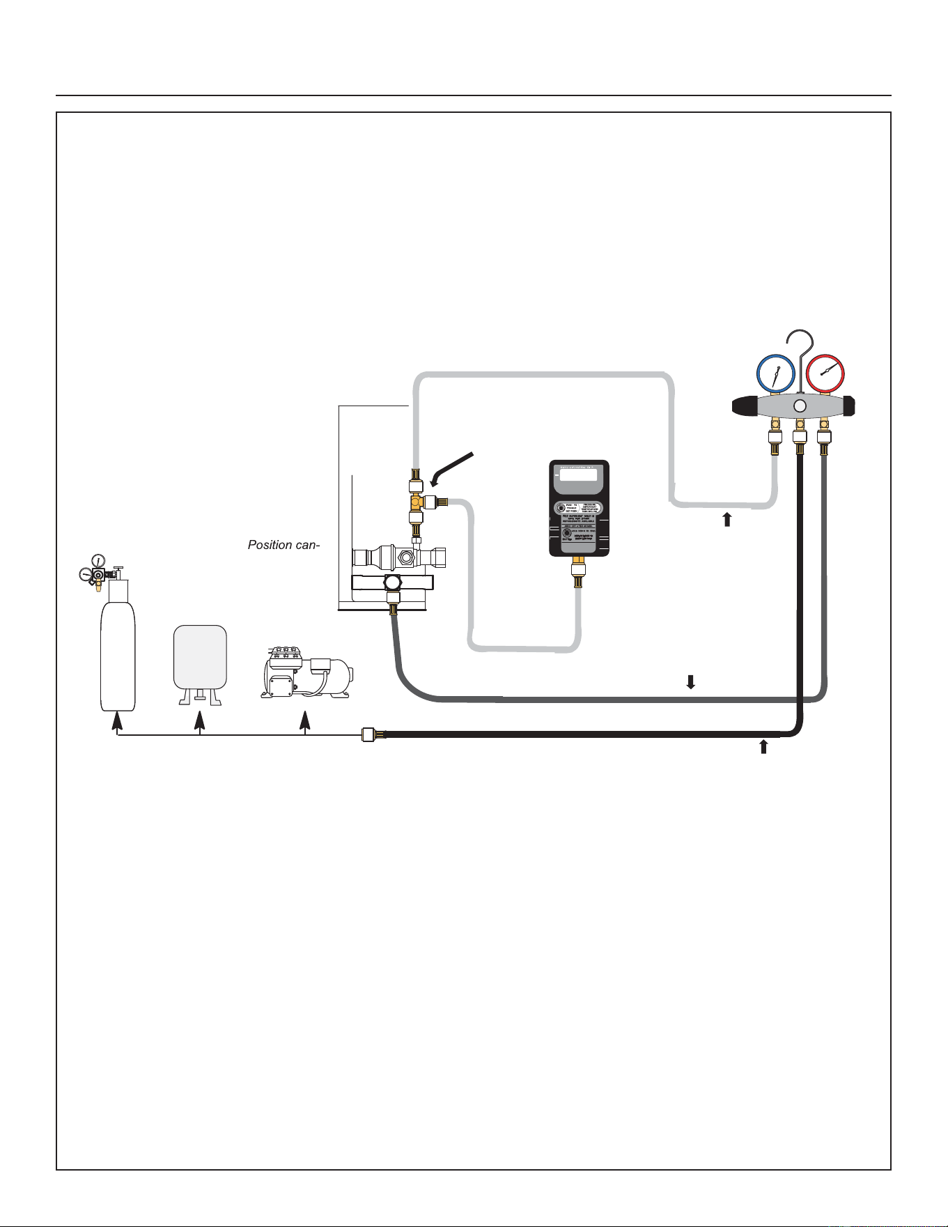
Evacuating Line Set and Indoor Coil
1. CONNECT GAUGE SET
NOTE — Remove cores from service valves (if not already done).
A. Connect low side of manifold gauge set with 1/4 SAE in-line tee to vapor line service valve.
B. Connect high side of manifold gauge set to liquid line service valve.
C. Connect micron gauge available connector on the 1/4 SAE in-line tee.
D. Connect the vacuum pump (with vacuum gauge) to the center port of the manifold gauge set. The center port line
will be used later for both the R-454B and nitrogen containers.
OUTDOOR
UNIT
TO VAPOR
SERVICE VALVE
TO LIQUID LINE
SERVICE VALVE
MICRON
GAUGE
VACUUM PUMP
1/4 SAE TEE WITH SWIVEL
COUPLER
500
MANIFOLD
GAUGE SET
R-454B
RECOMMEND MINIMUM 3/8” HOSE
HIGH
LOW
NITROGEN
A
B
C
D
EVACUATE THE SYSTEM
.
NOTE -
ister to deliver liquid
refrigerant.
Installation Instructions
31-5000951 Rev. 0 27
Evacuating Line Set and Indoor Coil (cont)
2. EVACUATE THE SYSTEM
A. Open both manifold valves and start the vacuum pump.
B. Evacuate the line set and indoor unit to an absolute pressure of 23,000 microns (29.01 inches of mercury).
NOTE — During the early stages of evacuation, it is desirable to close the manifold gauge valve at least once. A rapid
rise in pressure indicates a relatively large leak. If this occurs, repeat the leak testing procedure.
NOTE — The term absolute pressure means the total actual pressure within a given volume or system, above the
absolute zero of pressure. Absolute pressure in a vacuum is equal to atmospheric pressure minus vacuum pressure.
C. When the absolute pressure reaches 23,000 microns (29.01 inches of mercury), perform the following:
• Close manifold gauge valves
• Close valve on vacuum pump
• Turn off vacuum pump
• Disconnect manifold gauge center port hose from vacuum pump
• Attach manifold center port hose to a dry nitrogen cylinder with pressure regulator set to 150 psig (1034 kPa) and
purge the hose.
• Open manifold gauge valves to break the vacuum in the line set and indoor unit.
• Close manifold gauge valves.
D. Shut off the dry nitrogen cylinder and remove the manifold gauge hose from the cylinder. Open the manifold gauge
valves to release the dry nitrogen from the line set and indoor unit.
E. Reconnect the manifold gauge to the vacuum pump, turn the pump on, and continue to evacuate the line set and
indoor unit until the absolute pressure does not rise above 500 microns (29.9 inches of mercury) within a 20-minute
period after shutting off the vacuum pump and closing the manifold gauge valves.
F. When the absolute pressure requirement above has been met, disconnect the manifold hose from the vacuum pump
and connect it to an upright cylinder of R-454B refrigerant. Open the manifold gauge valve 1 to 2 psig in order to
release the vacuum in the line set and indoor unit.
G. Perform the following:
• Close manifold gauge valves.
• Shut off R-454B cylinder.
• Reinstall service valve cores by removing manifold hose from service valve. Quickly install cores
with core tool while maintaining a positive system pressure.
• Replace stem caps and secure finger tight, then tighten an additional one-sixth (1/6) of a turn as
illustrated.
Evacuating the system of non-condensables is critical for proper operation of the unit. Non-
condensables are defined as any gas that will not condense under temperatures and pressures present during
operation of an air conditioning system. Non-condensables and water suction combine with refrigerant to produce
substances that corrode copper piping and compressor parts.
WARNING
Possible equipment damage. Avoid deep vacuum operation. Do not use compressors to evacuate
a system. Extremely low vacuum can cause internal arcing and compressor failure. Damage caused by deep vacuum
operation will void warranty.
IMPORTANT
Use a thermocouple or thermistor electronic vacuum gauge that is calibrated in microns. Use an
instrument capable of accurately measuring down to 50 microns.
1
2
3
4
5
6
7
8
9
10
11
12
1/6 TURN
Installation Instructions
28 31-5000951 Rev. 0
Electrical
In the U.S.A., wiring must conform with current local codes
and the current National Electric Code (NEC). In Canada,
wiring must conform with current local codes and the
current Canadian Electrical Code (CEC).
Refer to the furnace or air handler installation instructions
for additional wiring application diagrams and refer to unit
nameplate for minimum circuit ampacity and maximum
overcurrent protection size.
24VAC TRANSFORMER
Use the transformer provided with the furnace or air
handler for low-voltage control power (24VAC - 40 VA
minimum).
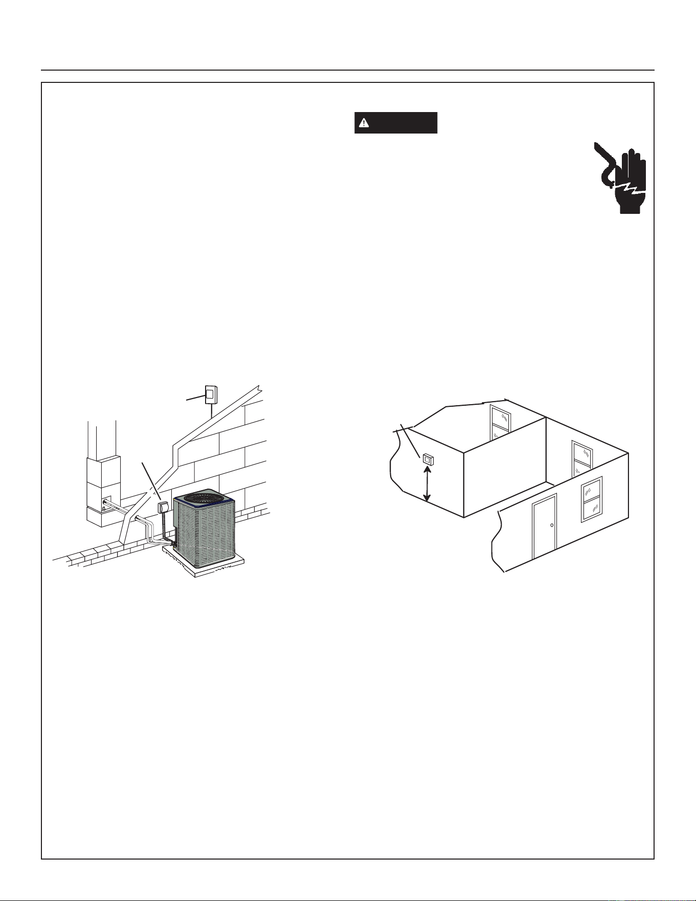
SIZE CIRCUIT AND INSTALL SERVICE DISCONNECT
SWITCH
Refer to the unit nameplate for minimum circuit ampacity,
and maximum fuse or circuit breaker (HACR per NEC).
Install power wiring and properly sized disconnect switch.
SERVICE
DISCONNECT
SWITCH
MAIN FUSE BOX/
BREAKER PANEL
NOTE — Units are approved for use only with copper
conductors. Ground unit at disconnect switch or to an
earth ground.
WARNING
Electric Shock Hazard. Can cause injury
or death. Unit must be properly grounded in
accordance with national and local codes. Line
voltage is present at all components when unit
is not in operation on units with singlepole
contactors. Disconnect all remote electric
power supplies before opening access panel.
Unit may have multiple power supplies.
INSTALL THERMOSTAT
Install room thermostat (ordered separately) on an inside
wall approximately in the center of the conditioned area
and 5 feet (1.5m) from the floor. It should not be installed
on an outside wall or where it can be affected by sunlight
or drafts.
THERMOSTAT
5 FEET
(1.5M)
NOTE — 24VAC, Class II circuit connections are made in
the control panel.
Installation Instructions
31-5000951 Rev. 0 29
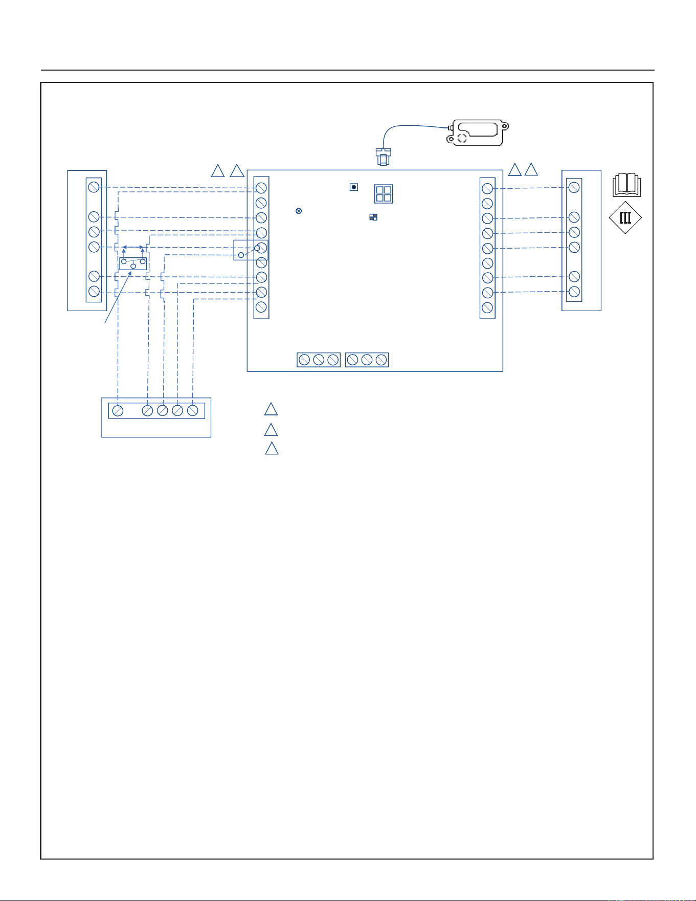
Electrical (cont)
Air Handler
1
2
Thermostat / Outdoor Unit Terminal Block (BLACK)
Indoor Unit Terminal Block (BLUE)
Class II Voltage Field Wiring
Single-Stage Heat Pump
Optional
N.C. Condensate
Float Switch
TSTAT
INDOOR
NO COM NCNO COM NC
ZONING ALARM
W1
W2
G
R
O/B
DS
C
Y2
Y1
W1
W2
G
R
O/B
DS
C
Y2
Y1
SENSOR #1
SW1
SW2
LED
W1
C
G
R
O
Y1
W1
C
G
R
O
Y1
W1
C
O
Y1
R
2
1
RDS Sensor
Thermostat
RDS Blower Control Board - 24 Volt
Cat # (27A05)
3
3
3
Heat Pump with NAM-71 AHU with Factory Installed RDS Control Field Wiring Diagram
Installation Instructions
30 31-5000951 Rev. 0
Installation Instructions
System Operation
UNIT COMPONENTS
IMPORTANT
Some scroll compressors have an internal vacuum
protector that will unload scrolls when suction pressure
goes below 20 psig. A hissing sound will be heard when
the compressor is running unloaded. Protector will
reset when low pressure in system rises above 40 psig.
DO NOT REPLACE COMPRESSOR.
The outdoor unit and indoor blower cycle on demand from
the room thermostat. If the thermostat blower switch is in
the ON position, the indoor blower operates continuously.
Bi-Flow Liquid line Filter Drier
The unit is equipped with a large-capacity bi-flow filter drier
which keeps the system clean and dry. If replacement is
necessary, order another of the same design and capacity.
The replacement filter drier must be suitable for use with
R-454B refrigerant.
Low Pressure Switch (S87)
The NS16H is equipped with an auto-reset low pressure
switch which is located on the vapor line. The switch shuts
off the compressor when the vapor pressure falls below
the factory setting. This switch, which is ignored during
defrost operation, closes at pressures at or above 40 ± 5
psig (276 ± 34 kPa) and opens at 25 ± 5 psig (172 ± 34
kPa). It is not adjustable.
High Pressure Switch (S4)
The NS16H is equipped with an auto-reset high pressure
switch (single-pole, single-throw) which is located on the
liquid line. The switch shuts off the compressor when
discharge pressure rises above the factory setting. The
switch is normally closed and is permanently adjusted to
trip (open) at 590 ± 15 psig (4068 ± 103 kPa).
Crankcase Heater (HR1)
Certain units are equipped with a belly band type
crankcase heater. HR1 prevents liquid from accumulating
in the compressor. The HR1 is controlled by a thermostat
switch integrated into the heater. On all units, the heater
is on when there is no compressor operation. Thermostat
switch closes at 45°F and opens at 65°F.
Charging
Verify the unit is electrically grounded before charging
the system. Extreme care shall be taken not to overfill the
refrigerating system.
Charge should be checked and adjusted using information
outlined in this section and in the tables provided on the
charging label on the unit’s control access panel.
R454B is a zeotropic blend of two refrigerants. At any
given refrigerant pressure, R454B will have two saturation
temperatures, a saturated liquid temperature and a
saturated vapor temperature. See R454B Refrigerant
Pressure Temperature Chart in the installation and
service manual for saturation temperatures.
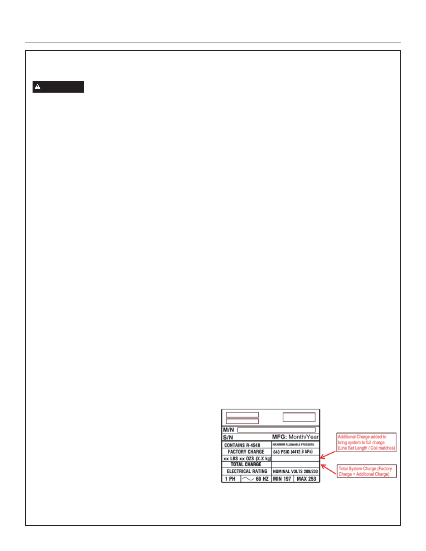
R454B Units must be charged with liquid refrigerant.
Follow conventional charging procedures when charging
the system. The technician is required to mark the total
charge of the installed system on the unit nameplate,
which includes the nameplate charge (factory charge) and
additional charge that is added to the system at the time
of installation.
7KH5%UHIULJHUDQWF\OLQGHUVDUHSURYLGHGZLWKDóފ/+
IODUHFRQQHFWLRQWKHUHIRUHDóފ/+IHPDOHIODUHDGDSWHU
will be required. Connect manifold gauges and hoses
following conventional charging procedures. Position the
R454B refrigerant cylinder to deliver liquid refrigerant.
NS16H unit is factory-charged with enough R454B
refrigerant to accommodate a 15-foot length of refrigerant
piping. For line lengths over 15 feet, add 3 oz of refrigerant
for every 5 feet of piping beyond 15 feet.
Initiate a call for cooling and allow the refrigerant pressures
and temperatures to stabilize. Adjust the charge to using
the subcooling method. The unit charging label provides
the target Subcooling Values. Record the liquid line
temperature. Measure the liquid line pressure and use
the value to determine the Saturated Liquid Temperature.
Calculate subcooling by subtracting the liquid line
temperature from the Saturated liquid temperature.
Subcooling = Saturated Liquid Temperature – Liquid
Line Temperature
Compare the results with the unit charging label.
Once system charging has been completed, the additional
charge and total charge must be marked on the unit
nameplate. See below.
Total Charge = Factory Charge + Additional charge.
The total charge is marked on the space adjacent to “Total
Charge”. See nameplate below.
Detailed information is given in the NS16H Installation
and Service Procedures manual, which is available on
GEAppliancesAirandWater.com.
31-5000951 Rev. 0 31
Installation Instructions
System Configuration
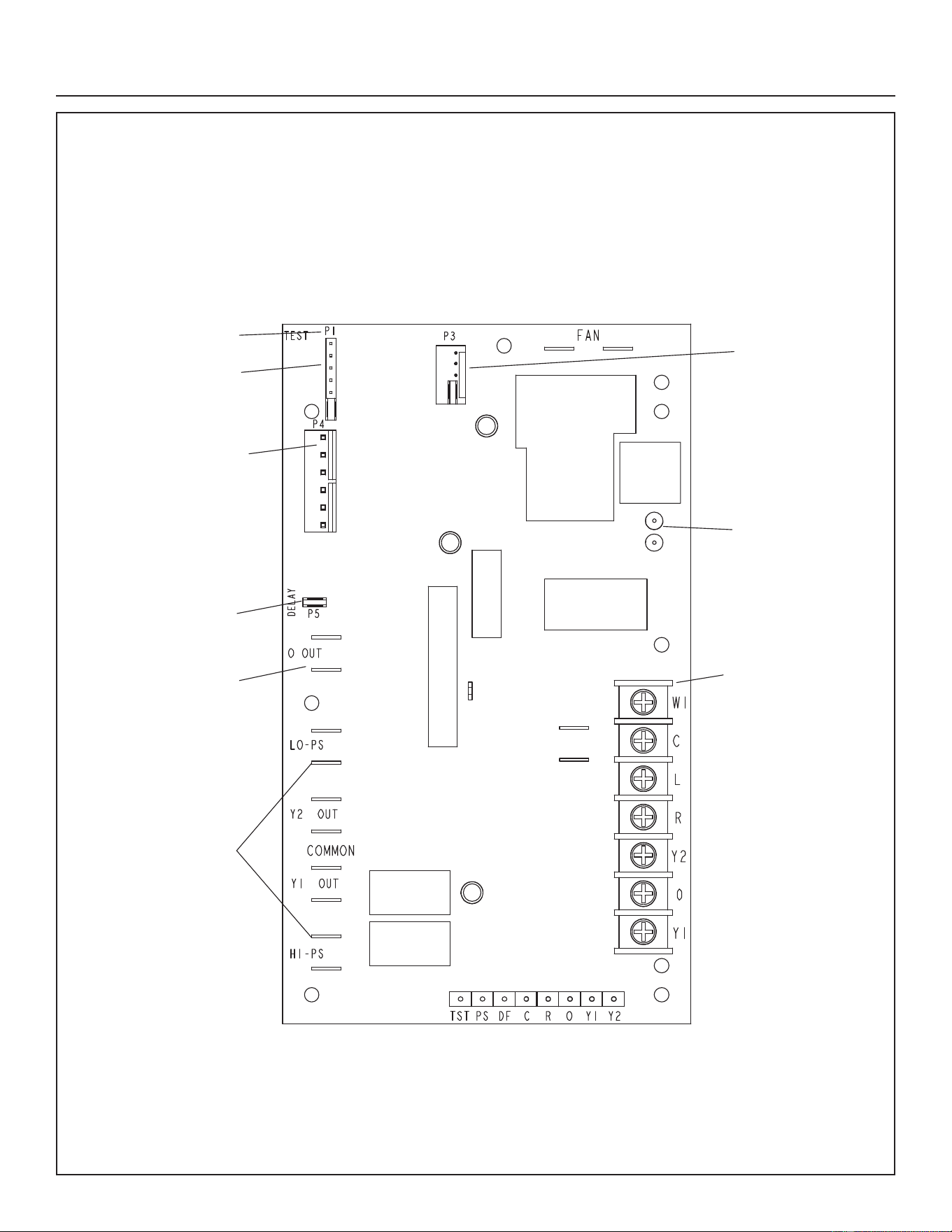
Demand Defrost Control (A108)
The demand defrost control measures differential temperatures to detect when the system is performing poorly
because of ice build-up on the outdoor coil. The control self-calibrates when the defrost system starts and after each
system defrost cycle. The demand defrost control components are shown below.
• Demand defrost control connections, jumpers and LED locations are shown below.
• Demand defrost control connections, jumpers and LED descriptions are listed in table on page 32.
• Demand defrost control status, fault and lockout LEDs are listed in table on page 35.
24V TERMINAL STRIP
CONNECTIONS
(P2)
DIAGNOSTIC LEDS
(DS1 AND DS2)
PRESSURE
SWITCH CIRCUIT
CONNECTIONS
TEST PINS (P1)
SENSOR CONNECTION
(COIL AND AMBIENT
SENSORS)
(P4)
REVERSING VALVE
(O OUT)
DELAY PINS
(P5)
NOMINAL DEFROST
SELECTION TIME
(P3)
DEFROST TERMINATION
PIN SETTINGS (P1)
Demand Defros
t
Control (A108)
32 31-5000951 Rev. 0
Installation Instructions
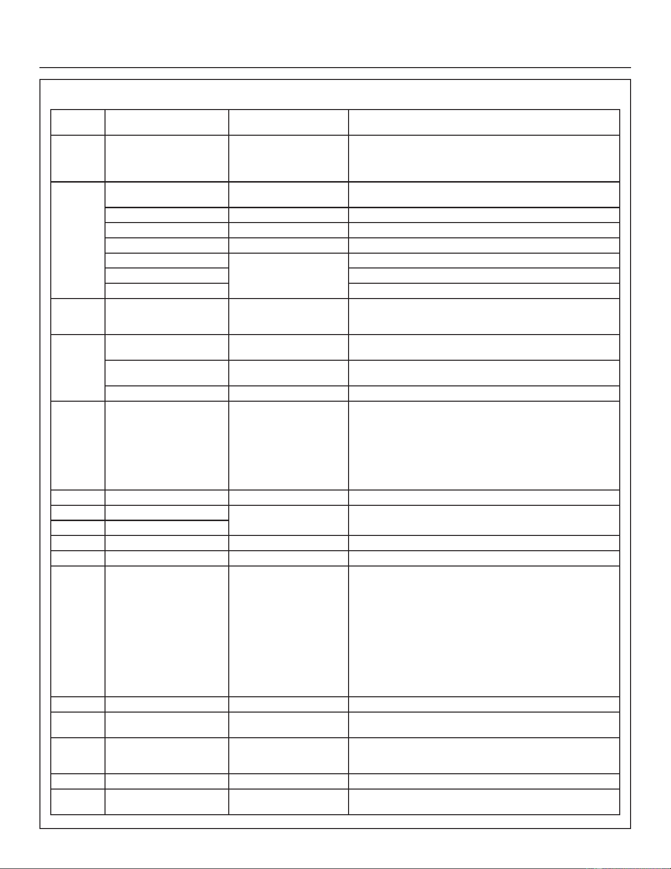
DEMAND DEFROST CONTROL (A108) INPUTS, OUTPUTS AND CONFIGURABLE SETTINGS
Control
Locations
Control Label or
Description
Purpose Function
P1 50, 70, 90, 100 Defrost Temperature
Termination Shunt (Jumper)
Pins
The demand defrost control (illustrated on Page 31) has selections
which are: 50, 70, 90, and 100°F (10, 21, 32 and 38°C). The shunt
termination pin is factory-set at 50°F (10°C). If the temperature shunt
is not installed, the default termination temperature is 90°F (32°C).
P2 W1 24VAC Thermostat Input /
Output
24VAC input / output from indoor thermostat to indoor unit.
C 24VAC Common 24VAC common.
L Thermostat Service Light Thermostat service light connection.
R 24VAC 24VAC.
T2 Thermostat Input Controls the second stage operation of the unit.
O Reversing valve solenoid.
Y1 Controls the operation of the unit.
P3 165, 140, 100, 60 Nominal defrost time
selection
The nominal defrost time selection input is provided by the position
of a selection shunt on the 0.100” P3 header. Options are 165, 140,
100 and 60 seconds. Default setting is 140 seconds.
P4 DIS-YEL Coil Sensor (P4-5) Ground connection for outdoor coil temperature sensor.
(P4-6) Connection for outdoor coil temperature sensor.
$0%%/$&. Ambient Sensor (P4-3) Ground connection for outdoor ambient temperature sensor.
(P4-4) Connection for outdoor ambient temperature sensor.
COIL-BROWN Discharge Sensor 1RGLVFKDUJHVHQVRULVXVHGUHSODFHGE\.UHVLVWRU
P5 DELAY Delay Mode The demand defrost control has a field-selectable function to
reduce occasional sounds that may occur while the unit is cycling
in and out of the defrost mode. When a jumper is installed on the
DELAY pins, the compressor will be cycled off for 30 seconds
going in and out of the defrost mode. Units are shipped with jumper
installed on DELAY pins.
NOTE - The 30-second off cycle is functional when TEST pins on
P1 are jumpered.
P6 TST, PS DF, C, R, O, Y1, Y2 Factory Test Connectors No field use.
DS1 RED LED Diagnostic LED Demand defrost control LEDs may be OFF, ON, or FLASHING to
indicate diagnostic conditions which are described in table 3.
DS2 GREEN LED
FAN TWO CONNECTORS Condenser Fan Operation These two connections provide power for the condenser fan.
O OUT O OUT 24 VAC output 24 VAC output connection for reversing valve.
LO-PS LO-PS Low-Pressure Switch When the low pressure switch trips, the demand defrost control
will cycle off the compressor, and the strike counter in the demand
defrost control will count one strike. The low pressure switch is
ignored under the following conditions:
• during the defrost cycle and 90 seconds after the termination of
defrost
• When ambient temperature is below 15°F, the Low pressure
switch is ignored for 10 minutes during compressor operation
before allowing the pressure switch to de-energize the
compressor.
• during 90 seconds following the start of the compressor
• during TEST mode.
Y2 OUT Y2 OUT 24 VAC Output 24 VAC output for second-stage compressor solenoid.
Y1 OUT Y1 OUT 24 VAC Common Output 24 VAC common output, switched for enabling compressor
contactor.
HS-PS HS-PS High-Pressure Switch When the high pressure switch trips, the demand defrost control
will cycle off the compressor, and the strike counter in the demand
defrost control will count one strike.
L L Service Light Output 24VAC service light output.
24V 24V 24 Volt Output 24VAC typically used to supply power to the System Operation
Monitor (LSOM). Not used in this system.

31-5000951 Rev. 0 33
Installation Instructions
Defrost System
This section addresses:
• Emergency Heat
• Defrost System Overview
• Defrost Control Connections, Jumper Settings and
Features
• Operational Mode Overview (Calibration, Normal and
Defrost)
• Defrost Cycle Actuation
EMERGENCY HEAT (AMBER LIGHT)
An emergency heat function is designed into some room
thermostats. This feature is applicable when isolation of
the outdoor unit is required, or when auxiliary electric
heat is staged by outdoor thermostats. When the room
thermostat is placed in the emergency heat position, the
outdoor unit control circuit is isolated from power and
field-provided relays bypass the outdoor thermostats. An
amber indicating light simultaneously comes on to remind
the homeowner that he is operating in the emergency heat
mode.
Emergency heat is usually used during an outdoor unit
shutdown, but it should also be used following a power
outage if power has been off for over an hour and the
outdoor temperature is below 50°F (10°C). System should
be left in the emergency heat mode at least six hours
to allow the crankcase heater sufficient time to prevent
compressor slugging.
DEFROST SYSTEM OVERVIEW
The control monitors ambient temperature, outdoor coil
temperature, and total run time to determine when a
defrost cycle is required. The coil temperature probe
is designed with a spring clip and is mounted between
the outlet of the TXV and the distributor. See coil sensor
location on Page 13, Figure 1 Typical Plumbing Location
arrangement drawing. The location of the coil sensor is
important for proper defrost operation.
NOTE – The demand defrost control accurately measures
the performance of the system as frost accumulates on the
outdoor coil. This typically will translate into longer running
time between defrost cycles as more frost accumulates on
the outdoor coil before the demand defrost control initiates
defrost cycles.
Demand Defrost Operation
The defrost control uses a time-dependent frost
accumulation duration demand defrost control algorithm
to provide a demand defrost when the system falls below
optimum levels. The demand defrost control algorithm
is reactive based upon the previous heat pump run time
between defrost cycles (frost accumulation time) and
the time spend in defrost (nominal defrost time). The
defrost control monitors ambient temperature, outdoor
coil temperature along with the compressor run time in
heating mode and defrost cycle time.
The outdoor unit control monitors compressor run time in
the heating mode when the outdoor coil temperature is
below 37°F and accumulates the frost accumulation time.
Once the frost accumulation time is met the unit control
will initiate a defrost cycle.
The unit will run in the defrost mode until the coil temperature
reaches the defrost termination temperature setpoint. The
maximum length of defrost cycle is 14 minutes and the
defrost cycle will automatically be terminated if the defrost
cycle exceeds 14 minutes.
Two consecutive low pressure switch trips while operating
in the heat pump heating mode will initiate a defrost cycle
to defrost that may occur during a weather related event
such as freezing rain.
Frost Accumulation Time
The frost accumulation time is the amount of time the
heat pump runs in the heating mode when the outdoor
coil temperature is below 37°F. The initial target frost
accumulation time is 90 minutes, but the control will
adjust the frost accumulation time higher or lower based
upon the previous defrost cycle time history. If the defrost
cycle time is short (70% or less of the defrost cycle time)
the defrost accumulation time will be increased by 30
minutes. If the defrost cycle time is long (130% or more
of the target defrost cycle time) the defrost accumulation
time will be decreased by 30 minutes. If the defrost
accumulation time is significantly longer (200% or more of
the target defrost cycle time) or if the defrost terminates at
the 14-minute maximum time, the frost accumulation time
is set to 30 minutes. No change is he frost accumulation
time is made if the frost accumulation time is close to the
target defrost cycle time (between 70% and 130% of the
target defrost cycle time).The defrost cycle time is counted
from the time the reversing valve is energized until the
defrost termination temperature reaches 50°F. The defrost
termination tempeature jumper setting does not affect the
defrost cycle time.

34 31-5000951 Rev. 0
Installation Instructions
Defrost System (cont)
Cold Climate Defrost
When the outdoor temperature is below 10°F, the frost
accumulation time is set to 360 minutes to reduce the
frequency of the defrost cycle to increase the system
efficiency. When the outdoor temperture is less the 10
degrees, there is less moisture in the air and defrost
frequency can be reduced. The defrost cycle resumes
normal operation when the outdoor temperature rises
above 15°F and the frost acumulation time is reset to 90
minutes.
NOTE – Colder climates may require a higher defrost
termination temperature setting to ensure the outdoor
coil is cleared of frost during defrost. If the outdoor coil
is not adequately cleared of frost, the heat pump may
experience reduced heating performance or damage to
the outdoor coil from the buildup of ice on the coil.
DEFROST CONTROL CONNECTIONS, JUMPERS
SETTINGS AND FEATURES
Defrost Temperature Termination Jumper Settings (P1)
The demand defrost control selections are: 50, 70, 90 and
100°F (10, 21, 32 and 38°C). The shunt termination pin
is factory set at 50°F (10°C). If temperature shunt is not
installed, default termination temperature is 90°F (32°C).
Test Pins (P1) Function
Placing the jumper on the field test pins (P1) allows the
technician to:
• Clear short cycle lockout
• Clear five-strike fault lockout
• Cycle the unit in and out of defrost mode
Place the unit in defrost mode to clear the coil
Nominal Defrost Time Selection Input (P3)
The nominal defrost time selection input is provided by the
position of a selection shunt on the 0.100” P3 header. If
the nominal defrost time shunt is not installed, the default
nominal defrost time shall be 140 seconds. The control
shall be provided from the factory with the shunt installed
in the 140 position. The nominal defrost time selection is
used as the value for the Nom_def_time variable.
Position Definitions for P3 Header:
• Connecting P3-1 and P3-2 will set the nominal defrost
time to 140 seconds.
• Connecting P3-2 and P3-3 will set the nominal defrost
time to 100 seconds.
• Connecting P3-3 and P3-4 will set the nominal defrost
time to 60 seconds.
• Connecting P3-4 and P3-5 will set the nominal defrost
time to 165 seconds.
Compressor Delay Mode (P5)
The demand defrost control has a field-selectable function
to reduce occasional sounds that may occur while the unit
is cycling in and out of the defrost mode. When a jumper is
installed on the DELAY pins, the compressor will be cycled
off for 30 seconds going in and out of the defrost mode.
Units are shipped with jumper installed on DELAY pins.
NOTE - The 30 second off cycle is NOT functional when
jumpering the TEST pins.
DEMAND DEFROST CONTROL (A108) DIAGNOSTIC
LEDS
The state (Off, On, Flashing) of two LEDs on the demand
defrost control (DS1 [Red] and DS2 [Green]) indicate
diagnostics conditions that are described in table 4.
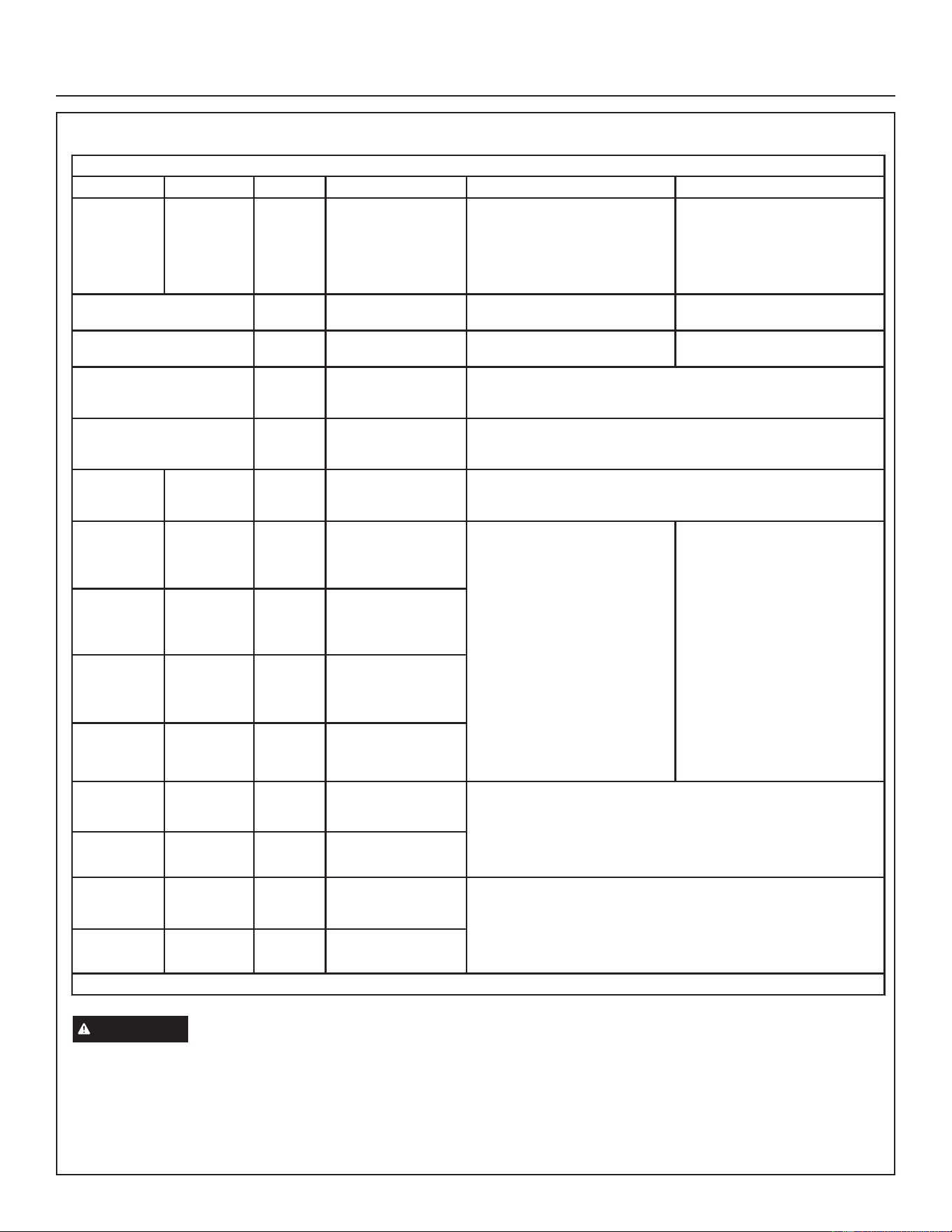
31-5000951 Rev. 0 35
Installation Instructions
DEMAND DEFROST CONTROL (A108) DIAGNOSTIC LEDS
DS1 and DS2 System Status, Fault and Lockout Codes
DS2 Green DS1 Red Type Condition / Code Possible Cause(s) Solution
OFF OFF Status Power Problem
No power (24V) to demand defrost
control terminals R and C or
demand defrost control failure.
1. Check control transformer power
(24V).
2. If power is available to demand
defrost control and LED(s) do
not light, replace demand defrost
control.
Simultaneous SLOW Flash Status Normal operation
Unit operating normally or in
standby mode.
None required
Alternating SLOW Flash Status
5-minute anti-short
cycle delay
Initial power up, safety trip, end of
room thermostat demand.
None required (jumper TEST pins
to override)
Simultaneous FAST Flash Fault
Ambient Sensor
Problem
Sensor being detected open or shorted or out of temperature range.
Demand defrost control will revert to time/temperature defrost operation.
(System will still heat or cool).
Alternating FAST Flash Fault Coil Sensor Problem
Sensor being detected open or shorted or out of temperature range.
Demand defrost control will not perform demand or time/temperature
defrost operation. (System will still heat or cool.)
ON ON Fault
Demand Defrost
Control Failure
Indicates that demand defrost control has internal component failure.
Cycle 24VAC power to demand defrost control. If code does not clear,
replace demand defrost control.
OFF SLOW Flash Fault Low Pressure Fault
• Restricted air flow over indoor or
outdoor coil.
• Improper refrigerant charge in
system.
• Improper metering device
installed or incorrect operation of
metering device.
• Incorrect or improper sensor
location or connection to system.
• Remove any blockages or
restrictions from coils and/or fans.
Check indoor and outdoor fan
motor for proper current draws.
• Check system charge using
subcooling method.
• Check system operating
pressures and compare to
unit subcooling tables in this
instruction or located on unit
access panel.
• Make sure all pressure switches
and sensors have secure
connections to system to prevent
refrigerant leaks or errors in
pressure and temperature
measurements.
OFF ON Lockout Low Pressure Lockout
SLOW Flash OFF Fault High Pressure Fault
ON OFF Lockout High Pressure Lockout
SLOW Flash ON Fault
Discharge Line
Temperature Fault
7KH16+KDVD.UHVLVWRULQVWDOOHGRQWKHGLVFKDUJHVHQVRU
connections. The high discharge temperature code should not occur.
If this code occurs, check for a shorted resistor on discharge sensor
connection.
During compressor operation, the demand defrost control will de-energize
the compressor contactor output (and the defrost output if active).
FAST Flash ON Lockout
Discharge Line
Temperature Lockout
OFF FAST Flash Fault
Discharge Sensor
Fault
7KH16+KDVD.UHVLVWRULQVWDOOHGRQWKHGLVFKDUJHVHQVRU
connections. The discharge sensor fault is detected if the 10k resistor is
open resistor on the discharge sensor connections. If this code occurs
check for a open resistor on discharge sensor connection. If the sensor
resistance is not within range after 90 seconds, the demand defrost one
fault. After 5 faults, the demand defrost control will lock out.
FAST Flash OFF Lockout
Discharge Sensor
Lockout
(DFKIDXOWDGGVVWULNHWRWKDWFRGH¶VFRXQWHUVWULNHVSHUFRGH /2&.287
IMPORTANT
After testing has been completed, properly reposition test jumper across desired timing pins
36 31-5000951 Rev. 0
Installation Instructions
Maintenance
DEALER
WARNING
Electric Shock Hazard.
Can cause injury or death. Unit must be
properly grounded in accordance with
national and local codes.
Line voltage is present at all components
when unit is not in operation on units
with single-pole contactors. Disconnect
all remote electric power supplies before
opening access panel. Unit may have
multiple power supplies.
WARNING
Improper installation, adjustment,
alteration, service or maintenance can cause property
damage, personal injury or loss of life. Installation and
service must be performed by a licensed professional
HVAC installer or equivalent, service agency, or the gas
supplier.
NOTICE
• Failure to follow instructions will cause damage to the
unit.
• This unit is equipped with an aluminum coil. Aluminum
coils may be damaged by exposure to solutions with a
pH below 5 or above 9. The aluminum coil should be
cleaned using potable water at a moderate pressure
(less than 50psi). If the coil cannot be cleaned using
water alone, GE Appliances recommends use of a coil
cleaner with a pH in the range of 5 to 9. The coil must be
rinsed thoroughly after cleaning.
• In coastal areas, the coil should be cleaned with potable
water several times per year to avoid corrosive buildup
(salt).
Maintenance and service must be performed by a qualified
installer or service agency. At the beginning of each
cooling season, the system should be checked as follows:
Outdoor Unit
1. Clean and inspect outdoor coil (may be flushed with a
water hose). Ensure power is off before cleaning.
2. Outdoor unit fan motor is pre-lubricated and sealed. No
further lubrication is needed.
3. Visually inspect all connecting lines, joints and coils for
evidence of oil leaks.
4. Check all wiring for loose connections.
5. Check for correct voltage at unit (unit operating).
6. Check amp draw on outdoor fan motor.
Motor Nameplate:_________ Actual:__________.
7. Inspect drain holes in coil compartment base and clean
if necessary.
NOTE – If insufficient heating or cooling occurs, the
unit should be gauged and refrigerant charge should be
checked.
Outdoor Coil
It may be necessary to flush the outdoor coil more frequently
if it is exposed to substances which are corrosive or which
block airflow across the coil (e.g., pet urine, cottonwood
seeds, fertilizers, fluids that may contain high levels of
corrosive chemicals such as salts)
• Outdoor Coil – The outdoor coil may be flushed with a
water hose.
• Outdoor Coil (Sea Coast) – Moist air in ocean locations
can carry salt, which is corrosive to most metal. Units that
are located near the ocean require frequent inspections
and maintenance. These inspections will determine the
necessary need to wash the unit including the outdoor
coil. Consult your installing contractor for proper intervals/
procedures for your geographic area or service contract.
Indoor Unit
1. Clean or change filters.
2. GE Appliances blower motors are prelubricated and
permanently sealed. No more lubrication is needed.
3. Adjust blower speed for cooling. Measure the pressure
drop over the coil to determine the correct blower CFM.
Refer to the unit information service manual for pressure
drop tables and procedure.
4. Belt Drive Blowers - Check belt for wear and proper
tension.
5. Check all wiring for loose connections.
6. Check for correct voltage at unit. (blower operating)
7. Check amp draw on blower motor.
Motor Nameplate:_________ Actual:__________.
Indoor Coil
1 - Clean coil if necessary.
2 - Check connecting lines, joints and coil for evidence of
oil leaks.
3 - Check condensate line and clean if necessary.
HOMEOWNER
Cleaning of the outdoor unit’s coil should be performed
by a trained service technician. Contact your dealer and
set up a schedule (preferably twice a year, but at least
once a year) to inspect and service your outdoor unit.
The following maintenance may be performed by the
homeowner.
31-5000951 Rev. 0 37
Installation Instructions
Maintenance (cont)
IMPORTANT
Sprinklers and soaker hoses should not be installed where
they could cause prolonged exposure to the outdoor unit
by treated water. Prolonged exposure of the unit to treated
water (i.e., sprinkler systems, soakers, waste water, etc.)
will corrode the surface of the steel and aluminum parts,
diminish performance and affect longevity of the unit.
Outdoor Coil
The outdoor unit must be properly maintained to ensure
its proper operation.
• Please contact your dealer to schedule proper inspection
and maintenance for your equipment.
• Make sure no obstructions restrict airflow to the outdoor
unit.
• Grass clippings, leaves, or shrubs crowding the unit can
cause the unit to work harder and use more energy.
.HHS VKUXEEHU\ WULPPHG DZD\ IURP WKH XQLW DQG
periodically check for debris which collects around the
unit.
Routine Maintenance
In order to ensure peak performance, your system must be
properly maintained. Clogged filters and blocked airflow
prevent your unit from operating at its most efficient level.
1. Air Filter – Ask your GE Appliances dealer to show
you where your indoor unit’s filter is located. It will be
either at the indoor unit (installed internal or external
to the cabinet) or behind a return air grille in the wall or
ceiling. Check the filter monthly and clean or replace it
as needed.
2. Disposable Filter – Disposable filters should be
replaced with a filter of the same type and size.
NOTE – If you are unsure about the filter required
for your system, call your GE Appliances dealer for
assistance.
3. Reusable Filter – Many indoor units are equipped with
reusable foam filters. Clean foam filters with a mild
soap and water solution; rinse thoroughly; allow filter
to dry completely before returning it to the unit or grille.
NOTE – The filter and all access panels must be in
place any time the unit is in operation.
4. Electronic Air Cleaner – Some systems are equipped
with an electronic air cleaner, designed to remove
airborne particles from the air passing through the
cleaner. If your system is so equipped, ask your dealer
for maintenance instructions.
5. Indoor Unit – The indoor unit’s evaporator coil is
equipped with a drain pan to collect condensate formed
as your system removes humidity from the inside air.
Have your dealer show you the location of the drain
line and how to check for obstructions. (This would also
apply to an auxiliary drain, if installed.)
Thermostat Operation
See the thermostat homeowner manual for instructions on
how to operate your thermostat.
Heat Pump Operation
Your new GE Appliances heat pump has several
characteristics that you should be aware of:
• Heat pumps satisfy heating demand by delivering large
amounts of warm air into the living space. This is quite
different from gas- or oil-fired furnaces or an electric
furnace which deliver lower volumes of considerably
hotter air to heat the space.
• Do not be alarmed if you notice frost on the outdoor coil
in the winter months. Frost develops on the outdoor coil
during the heating cycle when temperatures are below
45°F (7°C). An electronic control activates a defrost
cycle lasting 5 to 15 minutes at preset intervals to clear
the outdoor coil of the frost.
• During the defrost cycle, you may notice steam rising
from the outdoor unit. This is a normal occurrence. The
thermostat may engage auxiliary heat during the defrost
cycle to satisfy a heating demand; however, the unit
will return to normal operation at the conclusion of the
defrost cycle.
Extended Power Outage
The heat pump is equipped with a compressor crankcase
heater which protects the compressor from refrigerant
slugging during cold weather operation.
If power to your unit has been interrupted for several
hours or more, set the room thermostat selector to the
EMERGENCY HEAT setting to obtain temporary heat
without the risk of serious damage to the heat pump.
In EMERGENCY HEAT mode, all heating demand is
satisfied by auxiliary heat; heat pump operation is locked
out. After a six-hour compressor crankcase warm-up
period, the thermostat can be switched to the HEAT setting
and normal heat pump operation may resume.
Preservice Check
If your system fails to operate, check the following before
calling for service:
• Verify room thermostat settings are correct.
• Verify that all electrical disconnect switches are ON.
• Check for any blown fuses or tripped circuit breakers.
• Verify unit access panels are in place.
• Verify air filter is clean.
• If service is needed, locate and write down the unit model
number and have it handy before calling.
Accessories
For update-to-date information, see any of the following
publications:
• GE Appliances NS16H Product Specification
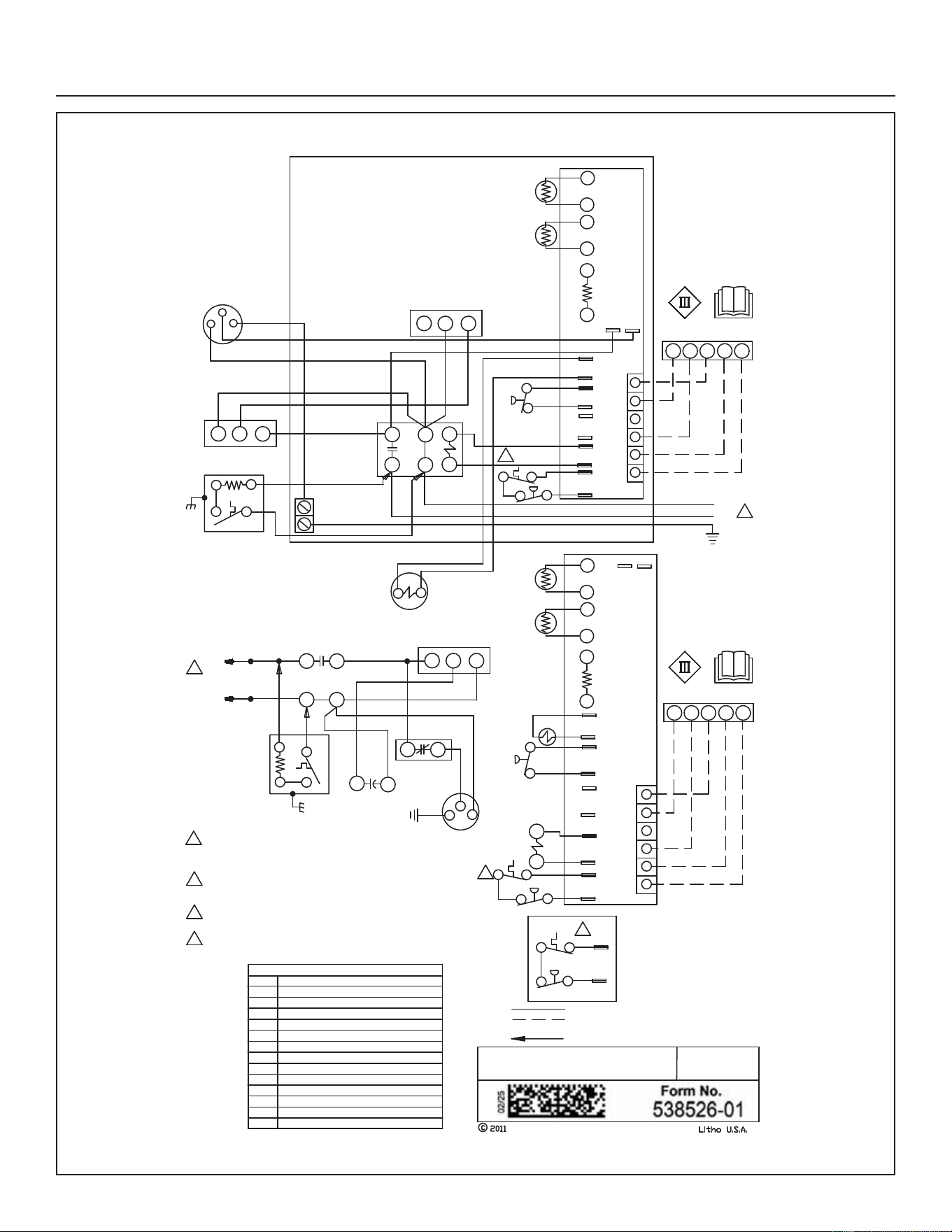
38 31-5000951 Rev. 0
Installation Instructions
Wiring and Sequence of Operation - Typical Unit Wiring
Supersedes
GROUND
LUG
L1
1
F
C
H
R
S
C
GREEN
RED
RED
RED
YELLOW
OUTDOOR
FAN
BLACK
DUAL
CAPACITOR
L2
L1
208-230/
60/
1
GROUND
COMPRESSOR
CONTACTOR
COMPRESSOR
K1-1
L2
208-230/60/1
BLACK
YELLOW
RED
RED
RED
H
C
B4
C12
CS
R
B1
KEY COMPONENT
B1
B4
DESCRIPTION
C12
HR1
K1,-1
S40
S87
S173
COMPRESSOR
MOTOR-OUTDOOR FAN
CAPACITOR-DUAL
HEATER-COMPRESSOR
CONTACTOR-COMPRESSOR
TERMOSTAT-CRANKCASE
SWITCH-LOW PRESS, COMP 1
SWITCH-THERMAL PROTECTION
FAN
CMC1
RED
BLK
HI-PS
O OUT
LO-PS
Y2-OUT
Y1-OUT
C
R
W1
O
Y1
THERMOSTAT
FAN
HI-PS
O OUT
LO-PS
DF
Y1-OUT
FAN
W1
C
L
R
O
Y1
C
R
W1
O
Y1
THERMOSTAT
W1
C
L
R
O
Y1
REVERSING
VALVE
RED
BLACK
RED
1
CMC1
L1
K1
HR1
S6
S41
SWITCH-DEFROST
THERMOSTAT-LOW AMBIENT
L1
VALVE-REVERSING
CMC1
CONTROL-DEFROST
CMC1
HI-PS
S173
S4
S4
SWITCH-HIGH PRESSURE
4
4
4
S173
S4
S4
S173
S87
SINGLE SPEED HP
S87
AMB
COIL
6
5
4
3
RT21
RT13
GROUND
AMB
COIL
6
5
4
3
RT21
RT13
DISCH
2
1
DISCH
2
1
GRN
1
2
3
S41 TO BE MOUNTED IN CONTROL BOX AND WIRED
IN PARALLEL WITH LOW PRESSURE SWITCH
NOTE-FOR USE WITH COPPER CONDUCTORS ONLY.
REFER TO UNIT RATING PLATE FOR MINIMUM CIRCUIT
AMOACITY AND MAXIMUM OVERCURRENT PROTECTION SIZE
NOTE-IF ANY WIRE IN THIS APPLIANCE IS
REPLACED, IT MUST BE REPLACED WITH WIRE OF LIKE
SIZ, RATING,INSULATION THICKNESS AND TERMINATION
4
S173 SWITCH USED ONLY IN UNITS EQUIPPED
WITH COMPRESSORS WHICH DO NOT INCLUDE
INTERNAL SWITCH
CRANKCASE
HEATER
S40
LINE VOLTAGE FIELD INSTALLED
CLASS II VOLTAGE FIELD WIRING
DENOTES OPTIONAL COMPONENTS
S40
CRANKCASE
HEATER
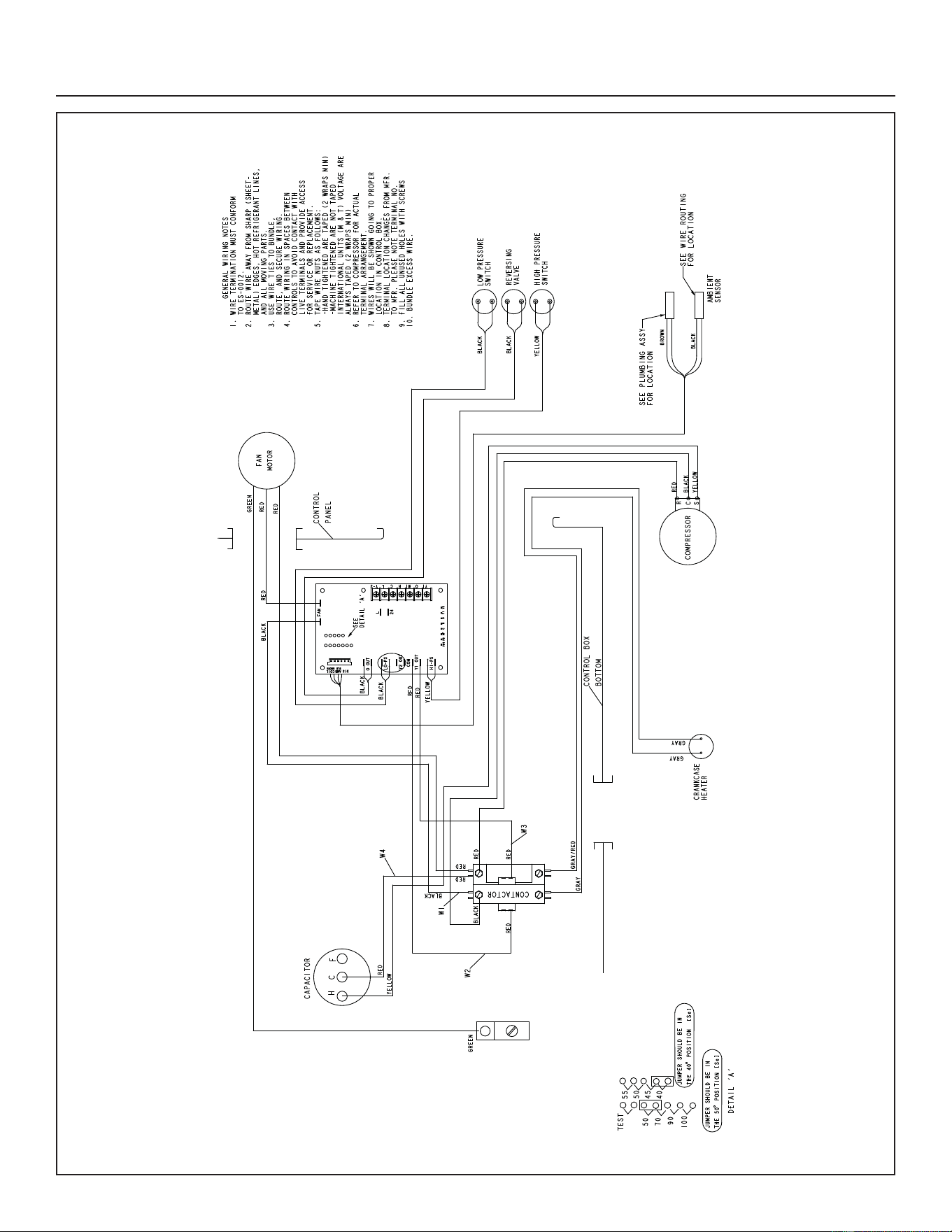
31-5000951 Rev. 0 39
Installation Instructions
Wiring and Sequence of Operation - Typical Factory Wiring
DEFROST COIL
SENSOR
40 31-5000951 Rev. 0
Operating Sequence
This is the sequence of operation for NS16H series units.
The sequence is outlined by numbered steps which
correspond to circled numbers on the adjacent diagram.
The steps are identical for both cooling and first stage
heating demand with the exception reversing valve L1
is energized during cooling demand and de-energized
during heating demand.
NOTE – Transformer in indoor unit supplies power (24
VAC) to the thermostat and outdoor unit controls.
COOLING:
Internal thermostat wiring energizes terminal O by cooling
mode selection, energizing the reversing valve L1.
1. Demand initiates at Y1 in the thermostat.
9$&HQHUJL]HVFRPSUHVVRUFRQWDFWRU.
. 12 FORVHV HQHUJL]LQJ FRPSUHVVRU % DQG
outdoor fan motor (B4).
END OF COOLING DEMAND:
4. Demand is satisfied. Terminal Y1 is de-energized.
&RPSUHVVRUFRQWDFWRU.LVGHHQHUJL]HG
.RSHQVDQGFRPSUHVVRU%DQGRXWGRRUIDQPRWRU
(B4) are de-energized and stop immediately.
FIRST STAGE HEAT:
Internal thermostat wiring de-energizes terminal O by
heating mode selection, de-energizing the reversing valve
L1. See steps 1, 2 and 3.
End of FIRST STAGE HEAT:
See steps 4, 5 and 6.
DEFROST MODE:
When a defrost cycle is initiated, the control energizes
the reversing valve solenoid and turns off the condenser
fan. The control will also put 24VAC on the “W1” (auxiliary
heat) line. The unit will stay in this mode until either the
coil sensor temperature is above the selected termination
temperature, the defrost time of 14 minutes has been
completed, or the room thermostat demand cycle has been
satisfied. (If the temperature select shunt is not installed,
the default termination temperature will be 90°F.) If the
room thermostat demand cycle terminates the cycle, the
defrost cycle will be held until the next room thermostat
demand cycle. If the coil sensor temperature is still below
the selected termination temperature, the control will
continue the defrost cycle until the cycle is terminated in
one of the methods mentioned above.
Servicing Units Void of Charge
If the outdoor unit is void of refrigerant, clean the system
using the procedure described below.
1. Leak check system using procedure outlined on
page 25.
2. Evacuate the system using procedure outlined on
page 26.
3. Use nitrogen to break the vacuum and install a new
filter drier in the system.
4. Evacuate the system again using procedure outlined
on page 26.
5. Weigh in refrigerant.
Start-Up
IMPORTANT
If unit is equipped with a crankcase
heater, it should be energized 24 hours before unit start-
up to prevent compressor damage as a result of slugging.
1. Rotate fan to check for binding.
2. Inspect all factory and field-installed wiring for loose
connections.
3. After evacuation is complete, open the liquid line and
suction line service valves to release the refrigerant
charge (contained in outdoor unit) into the system.
4. Replace the stem caps and tighten as specified in
Operating Service Valves on page 15.
5. Check voltage supply at the disconnect switch. The
voltage must be within the range listed on the unit’s
nameplate. If not, do not start the equipment until you
have consulted with the power company and the voltage
condition has been corrected.
6. Set the thermostat for a cooling demand. Turn on power
to the indoor indoor unit and close the outdoor unit
disconnect switch to start the unit.
7. Check system for sufficient refrigerate by using
the procedures listed under Start-Up and Charging
Procedures.
8. Recheck voltage while the unit is running. Power must
be within range shown on the nameplate.
Installation Instructions
31-5000951 Rev. 0 41
Decommissioning
Before carrying out this procedure, it is essential that
the technician is completely familiar with the equipment
and all its detail. It is recommended good practice that all
refrigerants are recovered safely.
Prior to the task being carried out, an oil and refrigerant
sample shall be taken in case analysis is required prior to
re-use of recovered refrigerant. It is essential that electrical
power is available before starting decommissioning.
a) Become familiar with the equipment and its operation.
b) Isolate system electrically.
c) Before attempting the procedure, ensure that:
• mechanical handling equipment is available, if required,
for handling refrigerant cylinders;
• all personal protective equipment is available and
being used correctly;
• the recovery process is supervised at all times by a
competent person;
• recovery equipment and cylinders conform to the
appropriate standards.
d) Pump down refrigerant system, if possible.
e) If a vacuum is not possible, make a manifold so that
refrigerant can be removed from various parts of the
system.
f) Make sure that cylinder is situated on the scales before
recovery takes place.
g) Start the recovery machine and operate in accordance
with instructions.
h) Do not overfill cylinders (no more than 80% volume
liquid charge).
i) Do not exceed the maximum working pressure of the
cylinder, even temporarily.
j) When the cylinders have been filled correctly and the
process completed, make sure that the cylinders and
the equipment are removed from site promptly and all
isolation valves on the equipment are closed off.
k) Recovered refrigerant shall not be charged into another
REFRIGERATING SYSTEM unless it has been cleaned
and checked.
IMPORTANT
Equipment shall be labelled stating that
it has been decommissioned and emptied of refrigerant.
The label shall be signed and dated. Ensure that there are
labels on the equipment that state the flammability of the
refrigerant used.
Installation Instructions
42 31-5000951 Rev. 0
Installation Instructions
R-454B Refrigerant Pressure-Temperature Chart
Pressure
(psig)
Saturated
Liquid
Temp (°F)
Saturated
Vapor
Temp (°F)
Pressure
(psig)
Saturated
Liquid
Temp (°F)
Saturated
Vapor
Temp (°F)
Pressure
(psig)
Saturated
Liquid
Temp (°F)
Saturated
Vapor
Temp (°F)
Pressure
(psig)
Saturated
Liquid
Temp (°F)
Saturated
Vapor
Temp (°F)
0 -58.9 -57.1 158 58.9 61.3 272 93 95.4 362 113.4 115.6
25 -19.2 -17.2 160 59.6 62 274 93.5 95.9 364 113.8 116
30 -13.9 -11.8 165 61.4 63.8 276 94 96.4 366 114.2 116.4
35 -9.0 -6.9 170 63.1 65.5 278 94.5 96.9 368 114.6 116.8
40 -4.4 -2.3 175 64.9 67.3 280 95 97.4 370 115 117.2
45 -0.2 1.9 180 66.6 69 282 95.5 97.9 372 115.4 117.6
50 3.7 5.9 185 68.2 70.6 284 96 98.4 374 115.8 118
55 7.5 9.7 190 69.8 72.2 286 96.5 98.8 376 116.2 118.4
60 11 13.2 195 71.4 73.8
288 97 99.3 378 116.6 118.8
65 14.4 16.6 200 73 75.4 290 97.5 99.8 380 117 119.2
70 17.6 19.8 202 73.6 76 292 97.9 100.3 382 117.4 119.6
75 20.6 22.9 204 74.2 76.6 294 98.4 100.7 384 117.7 119.9
80 23.6 25.9 206 74.9 77.3 296 98.9 101.2 386 118.1 120.3
85 26.4 28.7 208 75.5 77.9 298 99.4 101.7 388 118.5 120.7
90 29.1 31.4 210 76.1 78.5 300 99.8 102.2 390 118.9 121.1
95 31.7 34 212 76.7 79.1 302 100.3 102.6 392 119.3 121.5
100 34.3 36.6 214 77.3 79.7 304 100.8 103.1 394 119.7 121.9
102 35.3 37.6 216 77.9 80.2 306 101.2 103.5 396 120.1 122.2
104 36.2 38.6 218 78.4 80.8 308 101.7 104 398 120.5 122.6
106 37.2 39.5 220 79 81.4 310 102.1
104.4 400 120.8 123
108 38.1 40.5 222 79.6 82 312 102.6 104.9 405 121.8 123.9
110 39.1 41.4 224 80.2 82.6 314 103 105.4 410 122.7 124.9
112 40 42.4 226 80.8 83.1 316 103.5 105.8 415 123.6 125.8
114 40.9 43.3 228 81.3 83.7 318 103.9 106.2 420 124.6 126.7
116 41.8 44.2 230 81.9 84.3 320 104.4 106.7 425 125.5 127.6
118 42.7 45.1 232 82.4 84.8 322 104.8 107.1 430 126.4 128.5
120 43.6 46 234 83 85.4 324 105.3 107.6 435 127.3 129.4
122 44.5 46.9 236 83.6 86 326 105.7 108 440 128.2 130.2
124 45.4 47.7 238 84.1 86.5 328 106.2 108.5 445 129 131.1
126 46.2 48.6 240 84.7 87.1 330 106.6 108.9 450 129.9 132
128 47.1 49.4 242 85.2 87.6 332 107 109.3 460
131.6 133.7
130 47.9 50.3 244 85.8 88.1 334 107.5 109.7 470 133.3 135.3
132 48.8 51.1 246 86.3 88.7 336 107.9 110.2 480 135 137
134 49.6 51.9 248 86.8 89.2 338 108.3 110.6 490 136.7 138.6
136 50.4 52.8 250 87.4 89.7 340 108.8 111 500 138.3 140.2
138 51.2 53.6 252 87.9 90.3 342 109.2 111.5 510 139.9 141.8
140 52 54.4 254 88.4 90.8 344 109.6 111.9 520 141.5 143.3
142 52.8 55.2 256 88.9 91.3 346 110 112.3 530 143 144.8
144 53.6 56 258 89.5 91.8 348 110.5 112.7 540 144.5 146.3
146 54.3 56.7 260 90 92.4 350 110.9 113.1 550 146.1 147.8
148 55.1 57.5 262 90.5 92.9 352 111.3 113.5 560 147.5 149.2
150 55.9 58.3 264 91 93.4 354 111.7 114 570 149 150.7
152 56.6 59 266 91.5 93.9 356 112.1 114.4 580 150.5 152.1
154 57.4 59.8 268 92 94.4 358 112.5 114.8 590 151.9 153.5
156 58.1 60.5 270 92.5 94.9 360 112.9 115.2 600 153.3 154.8
Note
1. R-454B is a zeotropic blend and must be charged with liquid refrigerant only.
2. Saturated liquid temperature is used to calculate liquid subcooling.
3. Saturated vapor temperature is used to to calculate suction superheat.
4. See unit charging label for subcooling values and additional charging information.

31-5000951 Rev. 0 43
Notes
44 31-5000951 Rev. 0
Printed in the U.S.A.
All specifications and illustrations subject
to change without notice and without
incurring obligations.
Start-Up and Performance Checklist
Job Name Job no. Date
Job Location City State
Installer City State
Unit Model No. Serial No. Service Technician
Nameplate Voltage
Rated Load Ampacity Compressor Outdoor Fan
Maximum Fuse or Circuit Breaker
Electrical Connections Tight? Indoor Filter clean? Supply Voltage (Unit Off)
Indoor Blower RPM S.P. Drop Over Indoor (Dry) Outdoor Coil Entering Air Temp.
Discharge Pressure Suction Pressure Refrigerant Charge Checked?
Refrigerant Lines: Leak Checked? Properly Insulated? Outdoor Fan Checked?
Service Valves: Fully Opened? Caps Tight? Thermostat
Voltage With Compressor Operating Calibrated? Properly Set? Level?