RSE30 | RSE30B | RSG30/LP | RSG30B/LP
RSE36 | RSE36B | RSG36/LP | RSG36B/LP

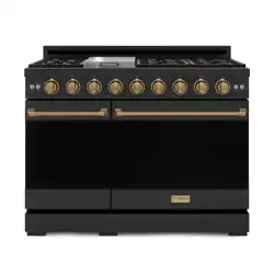
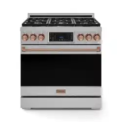
RSG MODELS
GAS/LP RANGE
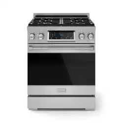
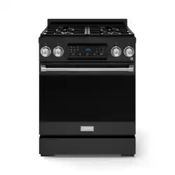
RSE MODELS
ELECTRIC RANGE
RSG30/LP | RSG36/LP | RSG30B/LP | RSG36B/LP
RSE30 | RSE36 | RSE30B | RSE36B
INSTALLATION INSTRUCTIONS
GORDON RAMSAY COLLECTION
BY THOR KITCHEN

1
TABLE OF CONTENTS
IMPORTANT INSTRUCTION . . . . . . . . . . . . . . . . . . . . . . . . . . . . . . . . . . . . . . . . . . . . . . . . . . . . . . . 2
1.1 Critical safety information . . . . . . . . . . . . . . . . . . . . . . . . . . . . . . . . . . . . . . . . . . . . . . . . . . . . . . . 2
1.2 Signal words explanation . . . . . . . . . . . . . . . . . . . . . . . . . . . . . . . . . . . . . . . . . . . . . . . . . . . . . . . . . . . . . . . . . . . . . 3
1.3 Intended use 3
1.4 IMPORTANT INSTRUCTION . . . . . . . . . . . . . . . . . . . . . . . . . . . . . . . . . . . . . . . . . . . . . . . . . . . . . . . 4
DELIVERY 7
2.1 Unpack 7
2.2 Appliance description 8
INSTALLATION 17
3.1 Important note to the installer 17
3.2 Clearances and dimensions 17
3.3 Install the handle 23
3.4 Attach/detach the oven door . . . . . . . . . . . . . . . . . . . . . . . . . . . . . . . . . . . . . . . . . . . . . . . . . . . . . . . . . . . . . . . . . 24
3.5 Attach/detach the kickplate. . . . . . . . . . . . . . . . . . . . . . . . . . . . . . . . . . . . . . . . . . . . . . . . . . . . . . . . . . . . . . . . . . 26
3.6 Install the burner knobs. . . . . . . . . . . . . . . . . . . . . . . . . . . . . . . . . . . . . . . . . . . . . . . . . . . . . . . . . . . . . . . . . . . . . 27
3.7 Installation for gas models (RSG30/LP, RSG36/LP, RSG30B/LP and RSG36B/LP only) . . . . . . . . . . . . 28
3.8 Electrical connection for gas range (RSG30/LP, RSG36/LP, RSG30B/LP and RSG36B/LP only) . . . . 32
3.9 Electrical connection for electric range (RSE30, RSE36, RSE30B and RSE36B only) 33
3.10 Install the back spacers 36
3.11 Move and level the appliance 37
3.12 Install anti-tip device. . . . . . . . . . . . . . . . . . . . . . . . . . . . 37
3.13 Place the bottom cover (RSG30/LP, RSG36/LP, RSG30B/LP and RSG36B/LP only) 40
3.14 Assemble the burners. . . . . . . . . . . . . . . . . . . . . . . . . . . . . . . . . . . . . . . . . . . . . . . . . . . . . . . . . . . . . . . . . . . . . . . 41
3.15 Perform a test run 42
3.16 Conditioning. . . . . . . . . . . . . . . . . . . . . . . . . . . . . . . . . . . . . . . . . . . . . . . . . . . . . . . . . . . . . . . . . . . . . . . . . . . . . . . . 42
TROUBLESHOOTING 43
WARRANTY 43
2
IMPORTANT INSTRUCTION
1.1 Critical safety information
WARNING: If the information in these instructions is not followed exactly,
a fire or explosion can result causing property damage, personal injury,
or death.
- Do not store or use gasoline or other flammable vapors and liquids in the
vicinity of this or any other appliance.
- WHAT TO DO IF YOU SMELL GAS:
•
Do not try to light any appliance.
•
Do not touch any electrical switch.
•
Do not use any phone in your building.
•
Immediately call your gas supplier from a neighbor's phone. Follow the
gas supplier's instructions.
•
If you cannot reach your gas supplier, call the fire department.
- Installation and service must be performed by a qualified installer,
service agency, or the gas supplier.
WARNING
Never Operate the Top Surface Cooking Section of this Appliance
Unattended.
•
Failure to follow this warning statement could result in fire,
explosion, or burn hazard that could cause property damage,
personal injury, or death.
•
If a fire should occur, keep away from the appliance and immediately
call your fire department.
DO NOT ATTEMPT TO EXTINGUISH AN OIL/GREASE FIRE WITH WATER.
WARNING
NEVER use this appliance as a space heater to heat or warm the room.
Doing so can result in carbon monoxide poisoning and overheating of
the oven.
3
IMPORTANT INSTRUCTION
WARNING
•
A child or adult can tip the appliance and be killed.
•
Install the anti-tip device to the wall/floor (see chapter 3.10 Install anti-tip device). Verify the anti-tip
device has been properly installed and engaged with the back of the appliance.
•
Engage the appliance to the anti-tip device by pushing that appliance all the way into the installation
location. Ensure the anti-tip device is re-engaged when the appliance is moved.
•
Re-engage the anti-tip device if the appliance is moved. Do not operate the appliance without the anti-
tip device in place and engaged.
•
See installation instructions for details.
•
Failure to do so can result in death or serious burns to children or adults.
To check the installation of the anti-tip device:
1. Remove any items on the cooktop (31).
2. Grasp the top rear edge of the appliance and carefully attempt to tilt it forward.
3. Verify that the anti-tip device is engaged.
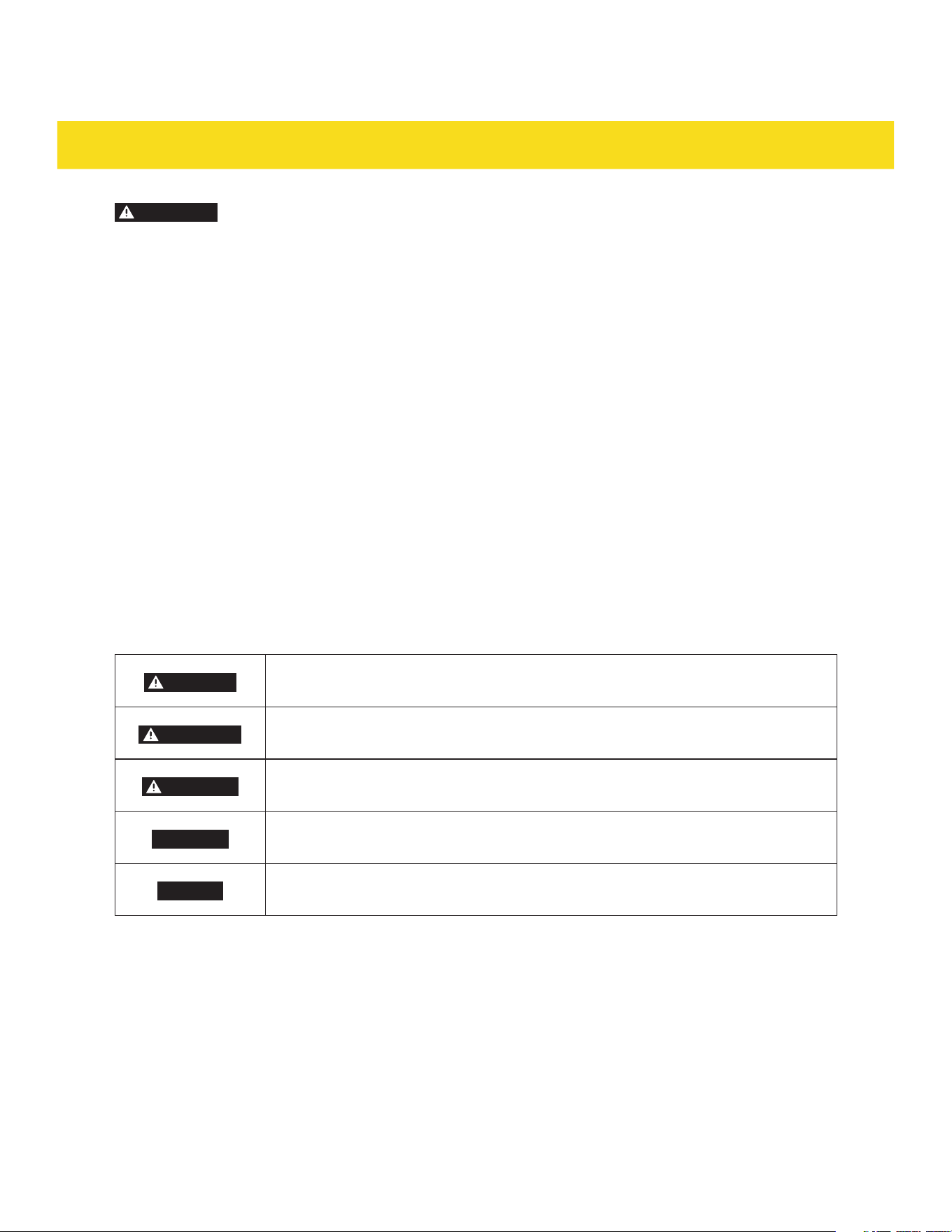
1.2 Signal words explanation
The following signal words are used in this manual
DANGER
This signal word indicates a hazardous situation which, if not avoided, will result
in death or serious injury.
WARNING
This signal word indicates a hazardous situation which, if not avoided, could
result in death or serious injury.
CAUTION
This signal word indicates a hazardous situation which, if not avoided, could
result in minor or moderate injury.
CAUTION
This signal word indicates a hazardous situation which, if not avoided, could
result in property damage.
NOTICE
This signal word is a preferred signal word to address tips and practices not
related to personal injury.
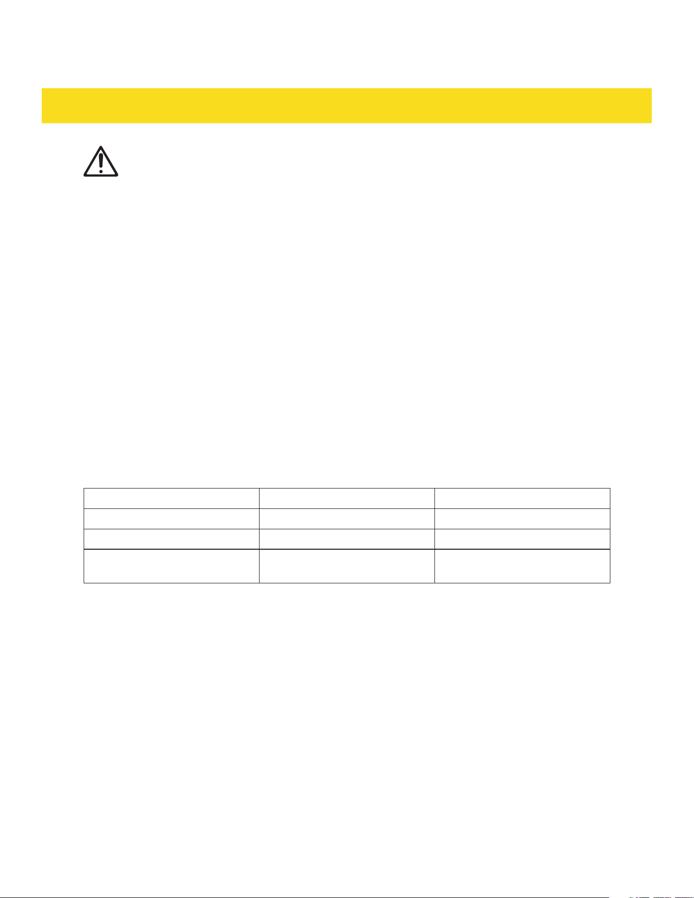
1.3 Intended use
•
This appliance is intended for cooking and preparing food.
•
This appliance is intended for household use only.
•
This appliance is intended to be used in dry indoor areas only.
•
Only use the appliance as mentioned in this manual. Any other use is considered improper and may
result in damage to property or injury to persons.
•
Potential injury from improper use.
•
The manufacturer or vendor cannot be held liable for damages or injury incurred through improper or
incorrect use.

4
IMPORTANT INSTRUCTION
1.4 IMPORTANT INSTRUCTION
For all models
This installation instructions is part of this appliance, and contains important information on setup and
use. Read this manual carefully, especially the IMPORTANT INSTRUCTION chapter, before using the
appliance. Failure to do so may result in personal injury and/or damage to the appliance.
•
Keep this manual for future use and reference. Make sure to include this manual when passing the
appliance on to third parties. If you require a digital copy of this manual, please contact customer
service.
•
The appliance must be installed in accordance with local codes. In the absence of local codes, follow
ANSI Z223.1/NFPA 54 standards in the U.S. or CSA B149.1 in Canada.
•
It is recommended to electrically ground the appliance during installation in accordance with local
codes. If local codes are not available, follow NFPA 70 or CSA C22.1 standards in Canada.
•
The ventilation area is located at the back of the appliance. The back of the appliance should not be in
direct contact with a wall/surface. Install the back spacers to the back of the appliance to maintain a
proper area for ventilation.
•
In the event of a power failure, do not attempt to use the appliance. If the power fails, always turn the
oven off. If the oven is not turned off and the power returns, the oven my begin to operate again. Food
left unattended could catch fire or spoil.
•
The maximum depth of cabinets installed above the cooktop (31) is 13" (33 cm).
•
Seal any openings in the wall behind the appliance and in the floor under the appliance.
•
If there is a cabinet above the appliance, install a noncombustible material on the bottom if that
cabinet in accordance with local codes. If local codes are not available, follow ANSI Z223.1/NFPA 54 or,
CSA B149.1. in Canada
•
Proper Installation - Be sure your appliance is properly installed and grounded by a qualified
technician.
•
Never Use Your Appliance for Warming or Heating the Room.
•
Do Not Leave Children Alone - Children should not be left alone or unattended in area where
appliance is in use. They should never be allowed to sit or stand on any part of the appliance.
•
Wear Proper Apparel - Loose-fitting or hanging garments should never be worn while using the
appliance.
•
User Servicing - Do not repair or replace any part of the appliance unless specifically recommended in
the manual. All other servicing should be referred to a qualified technician.
•
Storage in or on Appliance - Flammable materials should not be stored in an oven or near surface
units.
•
Do Not Use Water on Grease Fires - Smother fire or flame or use dry chemical or foam-type
extinguisher.
•
Use Only Dry Potholders - Moist or damp potholders on hot surfaces may result in burns from steam.
Do not let potholder touch hot heating elements. Do not use a towel or other bulk cloth.
•
Use Proper Pan Size - The appliance is equipped with one or more surface units of different size.
Select utensils having flat bottoms large enough to cover the surface unit heating element. The use
of undersized utensils will expose a portion of the heating element to direct contact and my result in
ignition of clothing. Proper relationship of utensil to burner will also improve efficiency.

5
IMPORTANT INSTRUCTION
•
Never Leave Surface Units Unattended at High Heat Settings - Boilover can cause smoke and greasy
spillovers that may ignite.
•
Protective Liners - Do not use aluminum foil to line the surface of cooktop drip pan or oven bottoms.
Improper installation of these liners may result in a risk of electric shock, fire or damage to the
porcelain surface.
•
Glazed Cooking Utensils - Only specific types of glass, glass-ceramic, ceramic, earthenware, or other
glazed utensils are suitable for use on the cooktop, as they may break from sudden temperature
changes.
•
Utensil Handles Should Be Turned Inward and Not Extend Over Adjacent Surface units - To reduce
the risk of burns, ignition of flammable materials, and spillage due to unintentional contact with the
utensil, the handle of a utensil should be positioned so that it is turned inward, and does not extend
over adjacent surface units.
•
Use Caution When Opening Door - Let hot air or steam escape before removing or replacing food.
•
Do Not Heat Unopened Food Containers - Build-up of pressure may cause container to burst and
result in injury.
•
Keep Oven Exhaust Vent Unobstructed.
•
Placement of Oven Racks - Always place oven racks in the desired position while the oven is cool. If
moving a rack while the oven is hot, ensure potholders do not touch the heating elements.
•
Do Not Clean Door Gasket - The door gasket is essentials for a good seal. Care should be taken not to
rub, damage, or move the gasket.
•
Do not use a protective coating to line the oven and do not use commercial oven cleaner unless
Certified for use in a self cleaning oven.
•
Clean only the parts as suggested in the manual.
•
Before Using the Self-Clean Function: Remove the broiler pan, oven racks, and any other utensils.
•
DO NOT TOUCH SURFACE UNITS OR AREAS NEAR SURFACES UNITS - Surface units may be hot
even though they are dark in color. Areas near surface units may become hot enough to cause burns.
During and after use, do not touch, or let clothing or other flammable materials contact surface units
or areas near units until they have had sufficient time to cool. Among these areas are the surrounding
areas of cook-top, drip-pan, burners and cooking grates.
•
DO NOT TOUCH INTERIOR SURFACES OF OVEN - Interior surfaces of an oven become hot enough to
cause burns. During and after use, do not touch, or let clothing or other flammable materials contact
the interior surfaces of oven until they have had sufficient time to cool. Other surface of the appliance
may become hot enough to cause burns - among these surface are oven vent openings and surfaces
near these openings, oven doors, and windows of oven doors.
•
If the self-cleaning mode malfunctions, the display will show the error code "E10", accompanied by a
repeated beep tone. This indicates a malfunction in the self-cleaning mode. Turn off the appliance or
disconnect it from the power supply and have it serviced by a qualified technician.
CAUTION
Risk of fire and damage! Do not leave food or cooking utensils, etc., in oven during the
pyrolytic self cleaning mode of operation. Remove all items from the oven prior to initiating
the cleaning cycle. Before initiating the cleaning cycle, wipe off all excessive spillage, food
residue or debris that could potentially ignite. Maintain a safe distance from the appliance
during the cleaning cycle and avoid placing any flammable items or materials near the
appliance.
CAUTION
Risk of injury! Do not store items of interest to children in cabinets above a appliance or
on the backguard of a appliance - children climbing on the appliance to reach items could
be seriously injured.
6
IMPORTANT INSTRUCTION
WARNING
This appliance contains chemicals known to the State of California to cause cancer and/or
reproductive harm, and birth defects or other reproductive harm. For more information go to
www.P65Warnings.ca.gov.
For gas appliances only (RSG30/LP, RSG36/LP, RSG30B/LP, RSG36B/LP)
•
Line Pressure Testing Above 1/2 psi (3.5kPa): The range and its individual shutoff valve must be
disconnected from the gas supply piping system during any pressure testing of that system at test
pressures in excess of 1/2 psi (3.5 kPa).
•
Line pressure testing equal or less than 1/2 psi (3.5 kPa): The range must be isolated from the gas
supply piping system by closing its individual manual shutoff valve during any pressure testing of the
gas supply piping system at test pressures equal to or less than 1/2 psi (3.5 kPa).
•
The appliance should not be installed with a ventilation system that blows air downward toward the
appliance. This type of ventilation system may cause ignition and combustion problems with the gas
cooking appliance resulting in personal injury or unintended operation.
•
Do not use an air curtain or other overhead appliance hood (equipment that operates by blowing a
downward airflow onto a appliance) in conjunction with a gas appliance unless the hood and appliance
have been designed and tested in accordance with ANSI Z21.1 or CSA 1.1, and designed and tested for
combination use.
•
The maximum gas supply pressure, test pressure and the supplied pressure regulator setting of the
gas appliance supplied are as follows:
LP (Liquid Propane) in wc NG (Natural gas) in wc
Maximum gas supply pressure
13.0 10.0
Test pressure
≥11.0 ≥6.0
Appliance pressure regulator
setting for outlet pressure
10.0 5.0
•
Leak testing of the appliance shall be conducted in accordance with these instructions (see chapter
3.6 Installation for gas models (RSG30/LP, RSG36/LP, RSG30B/LP,RSG36B/LP only)).
•
A manual valve has to be installed in an accessible location in the gas piping external to the appliance
for the purpose of turning on or shutting off the gas supply to the appliance.
COMMONWEALTH OF MASSACHUSETTS
•
Installations and repairs must be performed by a qualified or licensed contractor, plumber, or gas
fitter, qualified or licensed by the state, province, or region where this appliance is being installed.
•
Use only gas shut-off valves approved for use within the state, province, or region where this
appliance is being installed.
•
A flexible gas connector, when used, must not exceed 3' (0.9 m).
For electrical appliances only (RSE30, RSE36, RSE30B, RSE36B)
•
Do Not Cook on a Broken Cooktop - If the cooktop is broken, cleaning solutions and spillovers may
seep through the cracks, posing a risk of electric shock. Contact a qualified technician immediately.

7
IMPORTANT INSTRUCTION
•
Clean Cook-Top With Caution Do Not clean cooktop when it's hot. Do Not clean cooktop when it's hot. - If a wet sponge or cloth is used to
wipe spills on a hot cooking area, be careful to avoid steam burn. Some cleaners can produce noxious
fumes if applied to a hot surface.
DELIVERY
2.1 Unpack
DANGER
Risk of suffocation! Keep any packaging materials away from children and pets – these
materials are a potential source of danger, e.g. suffocation.
•
If the appliance is too heavy, it is possible to remove the oven door (33) before moving the
appliance (see chapters 3.4 Attach/detach the oven door).
•
Do not remove any warning-type labels, the model and serial number label, or the tech sheet that is
located on the back of the appliance.
You will need:
•
People x 2
•
Furniture dolly x 1
•
Soft towel/blanket x 1
•
Cardboard/plywood at least 33 x 30"
(83.8 x 76.2 cm) in size
1. Cut the straps on the packaging.
2. Take off the top cover and then lift the whole cardboard sleeve off.
3. Unpack the appliance parts located on the foam tray on top of the appliance.
4. Take off the foam tray.
5. Open the oven door (33) and remove all packing materials and appliance parts.
6. Check the appliance for transport damages.
7. Review all components (see chapter 2.2 Appliance description).
8. Wrap the appliance with a soft towel/blanket to prevent any scratches when the appliance comes into
contact with the furniture dolly.
9. Stand at the back of the appliance and tilt in towards the furniture dolly.
10. Slide the furniture dolly underneath the appliance to remove the appliance from its packaging base.
11. Place the appliance onto cardboard or plywood to avoid damaging the floor surface.
8
DELIVERY
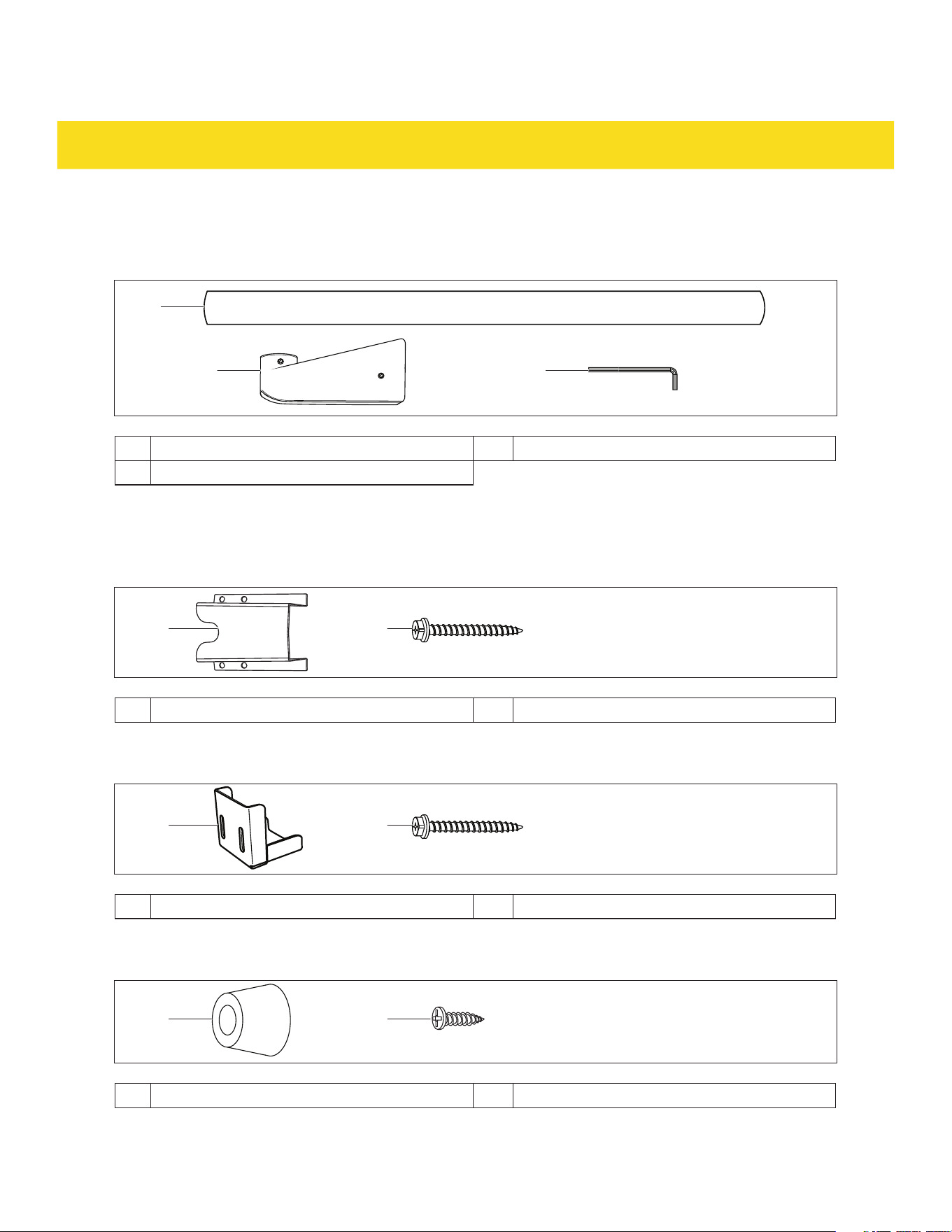
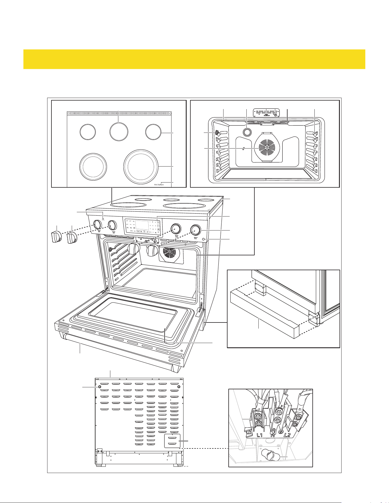
2.2 Appliance description
Door parts
1
2 3
1 Door handle x 1 3 Hex key x 1
2 Door side bracket x 2
Anti-tip kit
For model RSG30/LP and RSG30B/LP
54
4 Anti-tip device x 1 5 Anti-tip device screw x 4
For model RSE30, RSE30B, RSE36, RSE36B , RSG36/LP and RSG36B/LP
54
4 Anti-tip device x 1 5 Anti-tip device screw x 2
Spacer kit
76
6 Spacer x 2 7 Spacer screw x 2
9
DELIVERY
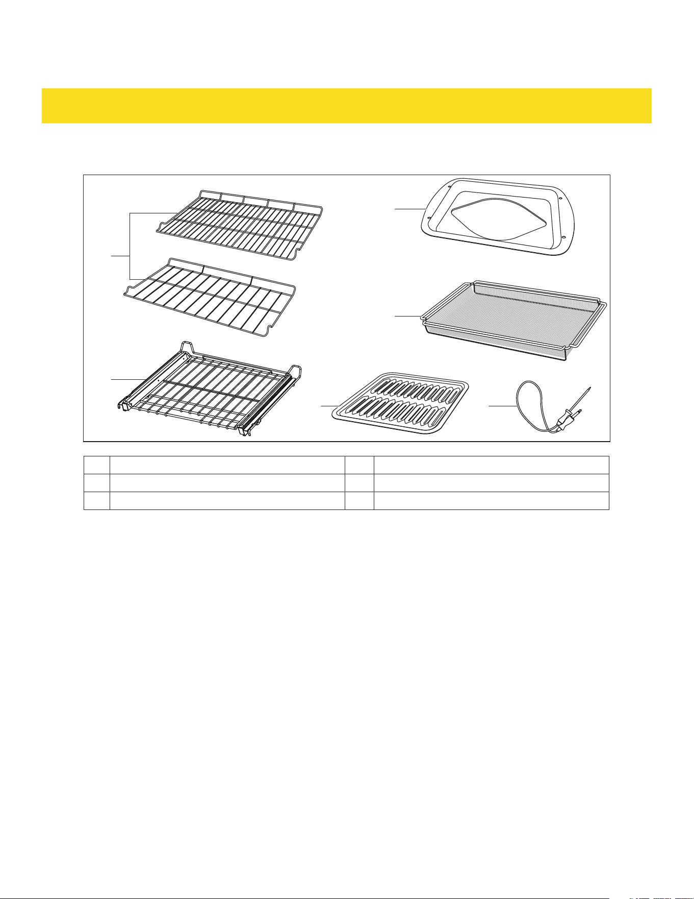
Baking accessories
10
11
129
8a
8b
For RSG36/LP, RSG36B/LP, RSE36, RSE36B
For RSG30/LP, RSG30B/LP, RSE30, RSE30B
8a Oven rack x 1 10 Broiler pan x 1
8b Telescopic oven rack x 1 11
1
Air fry basket x 1
9 Grid x 1 12
1
Probe x 1
1
Not included for RSG30/LP and RSG30B/LP
10
DELIVERY
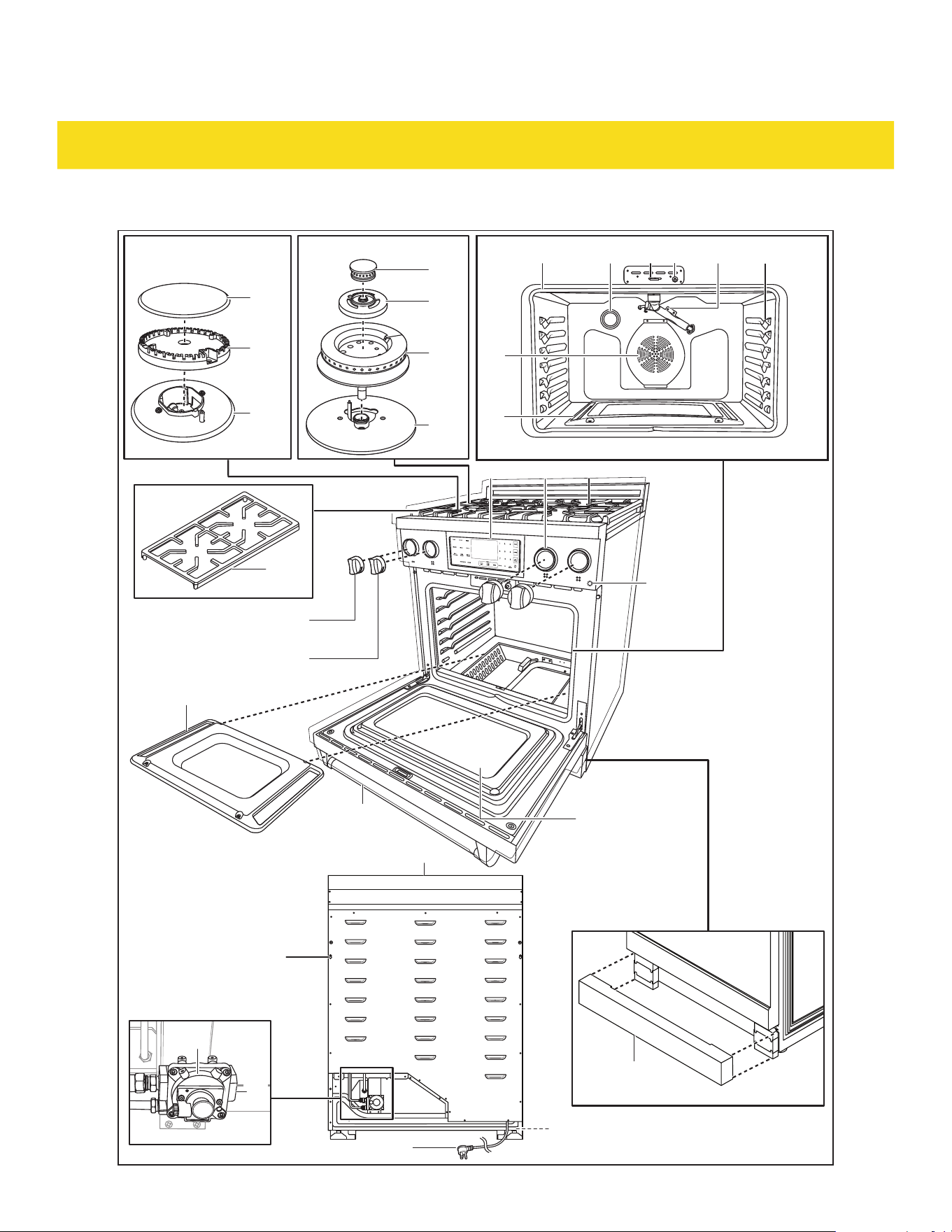
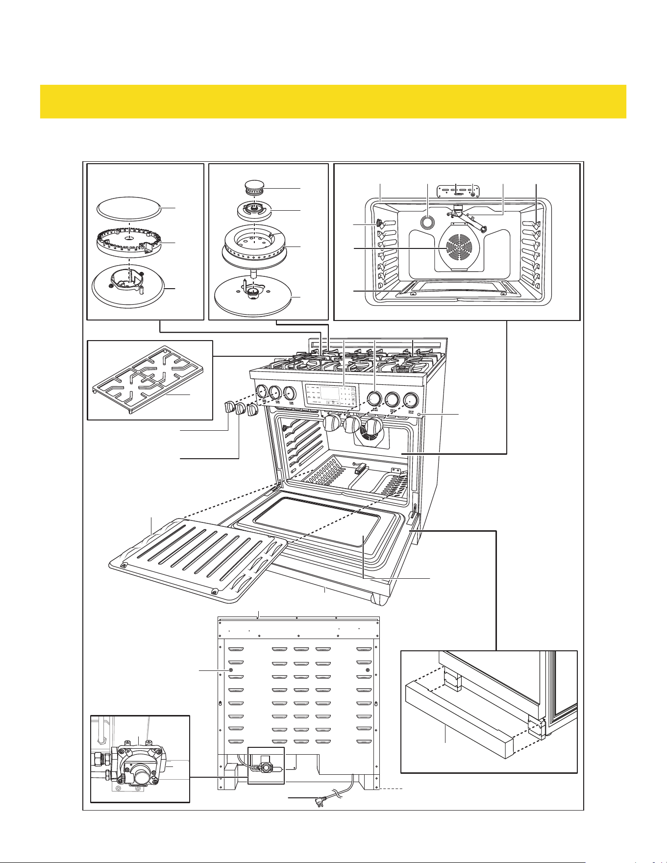
RSG30/LP and RSG30B/LP overview
Light
13
14
15
16
17
28
18
19
27
26
2120
34
33
37
22 23 25
40
35
29 30 31
43
41
38
42
39
24
32
36
53
11
DELIVERY
13 Burner cap x 2 29 Control panel
14 Burner head x 2 30 Knob bezel x 4
15 Burner base 31 Cooktop
16 Dual burner cap with flame spreader x 2 32 Viewing window
17 Dual burner simmer ring x 2 33 Oven door
18 Dual burner lower flame spreader x 2 34 Oven bottom cover
19 Dual burner base 35 Dual burner knob x 2
20 Oven cavity 36 Burner knob x 2
21 Light 37 Kickplate
22 Oven door lock 38 Exhaust vent
23 Oven door sensor 39 Foot x 4
24 Broiler burner 40 Power cord with plug
25 Rack positions 41 Spacer holes
26 Bake burner 42 Pressure regulator
27 Convection fan 43 Gas inlet
28 Cast iron cooking grate x 2 53 Oven light button
12
DELIVERY
RSG36/LP and RSG36B/LP overview
Light
13
14
15
16
17
28
18
19
27
26
44
2120
34
33
37
22 23 25
40
36
29 30 31
43
41
38
42
39
24
32
53
35
13
DELIVERY
13 Burner cap x 4 30 Knob bezel x 6
14 Burner head x 4 31 Cooktop
15 Burner base 32 Viewing window
16 Dual burner cap with flame spreader x 2 33 Oven door
17 Dual burner simmer ring x 2 34 Oven bottom cover
18 Dual burner lower flame spreader x 2 35 Dual burner knob x 2
19 Dual burner base 36 Burner knob x 4
20 Oven cavity 37 Kickplate
21 Light 38 Exhaust vent
22 Oven door lock 39 Foot x 4
23 Oven door sensor 40 Power cord with plug
24 Broiler burner 41 Spacer holes
25 Rack positions 42 Pressure regulator
26 Bake burner 43 Gas inlet
27 Convection fan 44 Probe port
28 Cast iron cooking grate x 3 53 Oven light button
29 Control panel 54 Hot surface indicator
14
DELIVERY
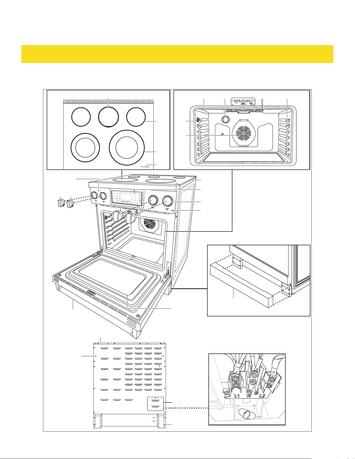
RSE30 and RSE30B overview
Light
51
52
39
31
30
46
47
50
41
27
44
37
33
45
222120
3635
48 2523
32
29
38
49
53
54
15
DELIVERY
20 Oven cavity 38 Exhaust vent
21 Light 39 Foot x 4
22 Oven door lock 41 Spacer holes
23 Oven door sensor 44 Probe port
25 Rack positions 45 Warning zone
27 Convection fan 46 Single cooking zone
29 Control panel 47 Dual cooking zone
30 Knob bezel x 4 48 Broil element
31 Cooktop 49 Burner On indicator
32 Viewing window 50 Terminal block
33 Oven door 51 Strain relief
35 Dual cooking zone knob x 2 52 Terminal block cover
36 Single cooking zone knob x 2 53 Oven light button
37 Kickplate 54 Hot surface indicator
16
DELIVERY
RSE36 and RSE36B overview
Light
51
52
39
31
30
46
47
50
41
27
44
37
33
45
222120
3635
48 2523
32
29
38
49
53
54
17
DELIVERY
20 Oven cavity 38 Exhaust vent
21 Light 39 Foot x 4
22 Oven door lock 41 Spacer holes
23 Oven door sensor 44 Probe port
25 Rack positions 45 Warning zone
27 Convection fan 46 Single cooking zone
29 Control panel 47 Dual cooking zone
30 Knob bezel x 6 48 Broil element
31 Cooktop 49 Burner On indicator
32 Viewing window 50 Terminal block
33 Oven door 51 Strain relief
35 Dual cooking zone knob x 2 52 Terminal block cover
36 Single cooking zone knob x 2 53 Oven light button
37 Kickplate 54 Hot surface indicator
INSTALLATION
3.1 Important note to the installer
•
Read all installation instructions included in this manual before installing the appliance.
•
Remove all packing materials from the appliance (see chapter 2.1 Unpack) before connecting it to the
electric and/or gas supply.
•
Adhere to all governing codes and ordinances during installation.
•
Install the anti-tip device to the wall/floor (see chapter 3.10 Install anti-tip device). Verify the anti-tip
device has been properly installed and engaged with the back of the appliance.
•
Leave these instructions with the consumer for future reference.
•
Important - Save for local electrical inspector's use.
3.2 Clearances and dimensions
•
Provide proper clearance between the appliance and adjacent combustible surfaces. These
dimensions must be met for safe use of the appliance.
•
The location of the electrical outlet and gas pipe opening may be adjusted to meet specific
requirements.
•
Seal any openings in the wall behind the appliance and in the floor under the appliance.
•
If there is a cabinet above the appliance, install a noncombustible material on the bottom if that
cabinet in accordance with local codes or, in the absence of local codes, with ANSI Z223.1/NFPA 54 or,
in Canada, CSA B149.1.
•
With the spacers installed, the appliance may be placed against the back wall.

18
DELIVERY
•
To eliminate the risk of burns or fire by reaching over heated surface units, cabinet storage space
located above the surface units should be avoided. If cabinet storage is to be provided, the risk can be
reduced by installing a appliance hood that projects horizontally a minimum of 5" (12.7 mm) beyond
the bottom of the cabinets.
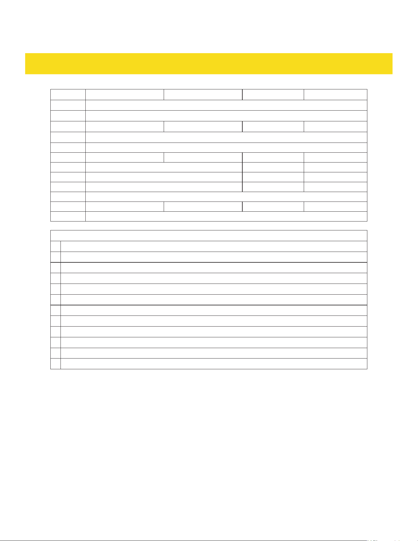
Dimensions
Width
Width
Depth (door open) Depth (door open)
Depth (door closed)
RSG models RSE models
Depth (door closed)
Height Height
Fig. 1
RSG30/LP,
RSG30B/LP
RSG36/LP,
RSG36B/LP
RSE30, RSE30B RSE36, RSE36B
Width
29 7/8" (75.9 cm) 35 7/8" (91.1 cm) 29 7/8" (91.1 cm) 29 7/8" (91.1 cm)
Depth (back panel to
front of handle)
29" (73.6 cm)29" (73.6 cm) 29" (73.6 cm)29" (73.6 cm) 29" (73.6 cm)29" (73.6 cm) 29" (73.6 cm)29" (73.6 cm)
Depth (door open)
47 1/2" (120.6 cm)47 1/2" (120.6 cm) 47 1/2" (120.6 cm)47 1/2" (120.6 cm) 47 1/2" (120.6 cm)47 1/2" (120.6 cm)
Height (from bottom to
top of side panel)
(± feet height)
36" ±1-3"
(91.4 cm
±2.5-7.6 cm)
36" ±1-3"
(91.4 cm
±2.5-7.6 cm)
36" ±1-3"
(91.4 cm
±2.5-7.6 cm)
36" ±1-3"
(91.4 cm
±2.5-7.6 cm)
47 1/2" (120.6 cm)
19
INSTALLATION
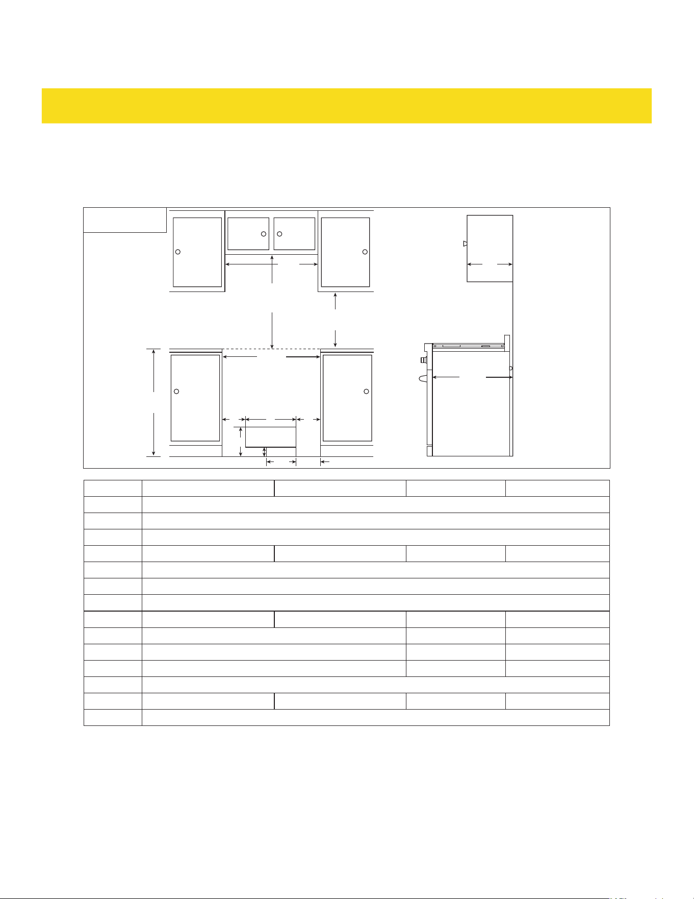
Clearances
Clearances for cooktops (31) with a cabinet on top
Electrical
Gas
C
B1/B2
Front view
Side view
A
D
G
FF
K
M
H
I
E
J
L
Fig. 2
RSG30/LP, RSG30B/LP RSG36/LP, RSG36B/LP RSE30, RSE30B RSE36, RSE36B
A 36" (91.4 cm)
B1 min 30" (76.2 cm)
B2 min 24" (60.9 cm)
C 30" (76.2 cm) 36" (91.4 cm) 30" (76.2 cm) 36" (91.4 cm)
D 18" (45.7 cm)
E 13" (33 cm)
F 5" (12.7 cm)
G 20" (50.8 cm) 26" (66 cm) 20" (50.8 cm) 26" (66 cm)
H 2" (5.1 cm) - -
I 9" (22.9 cm) - -
J 5" (12.7 cm) - -
K max 6" (15.24 cm)
L 30" (76.2 cm) 36" (91.44 cm) 30" (76.2 cm) 36" (91.44 cm)
M 24 3/4" (62.8 cm)
20
INSTALLATION
Legend
A Countertop height
B1 Minimum clearance above cooktop (31) for unprotected cabinet bottom
B2
Minimum clearance above cooktop (31) for protected cabinet bottom:
Cabinet bottom has to be protected with no less than 6.4 mm thick flame retardant millboard
covered with no less than No. 28 MSG sheet metal, 0.4 mm thick stainless steel, 0.6 mm thick
aluminum or 0.5 mm thick copper.
C Width of cabinet above cooktop (31)
D Clearance between cabinets and countertops
E Cabinet depth
F Clearance of the electrical component area from the side of the cabinet
G Width of the electrical component area
H Height of the gas connection area
I Width of the gas connection area
J Clearance of the gas connection area from the side of the cabinet
K Recommended height of the electrical component area
L Width of countertop cutout
M Depth of countertop cutout
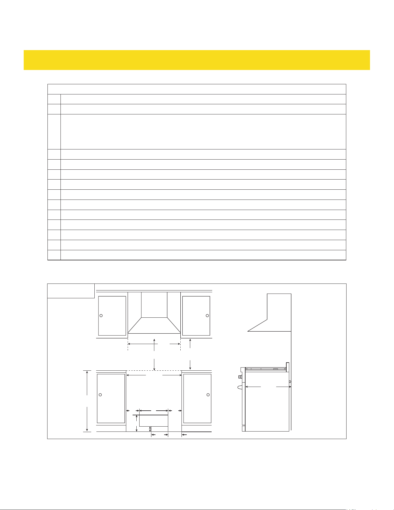
Clearances for cooktops (31) with a hood on top
C
B
A
D
F
Front view
Electrical
Gas
EE
J
K
L
G
H
I
Fig. 3
21
INSTALLATION
RSG30/LP, RSG30B/LP RSG36/LP, RSG36B/LP RSE30, RSE30B RSE36, RSE36B
A
36" (91.4 cm)
B
min 30" (76.2 cm)
C
30" (76.2 cm) 36" (91.4 cm) 30" (76.2 cm) 36" (91.4 cm)
D 18" (45.7 cm)
E
5" (12.7 cm)
F
20" (50.8 cm)
26" (66 cm)
20" (50.8 cm)
26" (66 cm)
G
2" (5.1 cm)
-
-
H
9" (22.9 cm)
-
-
I
5" (12.7 cm)
-
-
J
max 6" (15.24 cm)
K 30" (76.2 cm) 36" (91.44 cm) 30" (76.2 cm) 36" (91.44 cm)
L
24 3/4" (62.8 cm)
Legend
A Countertop height
B Minimum clearance above cooktop (31)
C Width of hood above cooktop (31)
D Clearance between cabinets and countertops
E Clearance of the electrical component area from the side of the cabinet
F Width of the electrical component area
G Height of the gas connection area
H
Width of the gas connection area
I Clearance of the gas connection area from the side of the cabinet
J Recommended height of the electrical component area
K Width of countertop cutout
L Depth of countertop cutout
22
INSTALLATION
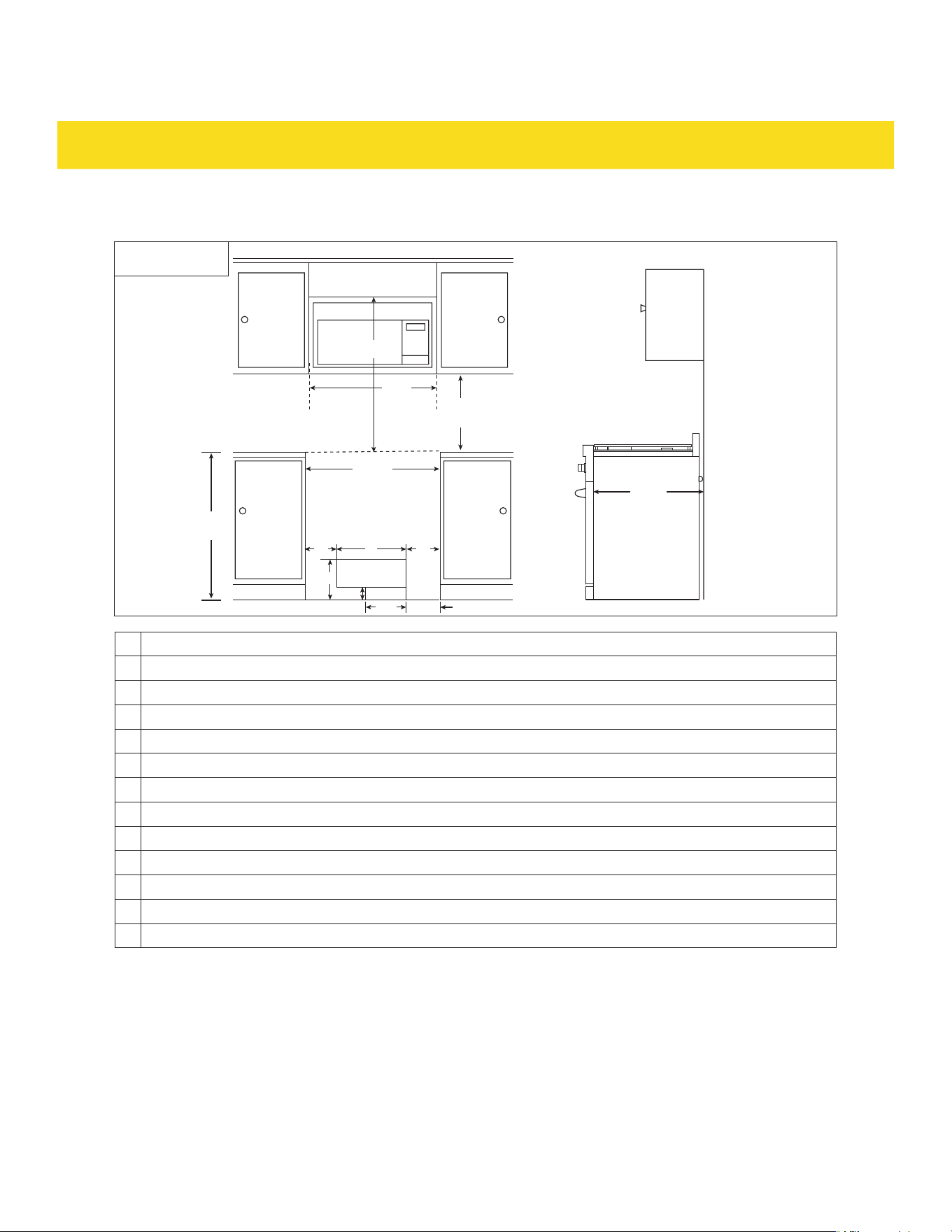
Clearances for cooktops (31) with an over-the-range microwave
C
B
A
D
H
G FF
K
L
M
I J
Front view
Electrical
Gas
Fig. 4
RSG30/LP, RSG30B/LP, RSE30B and RSE30
A
36" (91.4 cm)
B
min 30" (76.2 cm)
C
30" (76.2 cm)
D 18" (45.7 cm)
F
5" (12.7 cm)
G
20" (50.8 cm)
H
2" (5.1 cm)
I
9" (22.9 cm)
J
5" (12.7 cm)
K
max 6" (15.24 cm)
L
30" (76.2 cm)
M
24 3/4" (62.8 cm)
23
INSTALLATION
Legend
A Countertop height
B Width of over-the-range microwave
C From cooktop (31) to top of over-the-range microwave
D Clearance between cabinets and countertops
F Clearance of the electrical component area from the side of the cabinet
G Width of the electrical component area
H Height of the gas connection area
I Width of the gas connection area
J Clearance of the gas connection area from the side of the cabinet
K Recommended height of the electrical component area
L Width of countertop cutout
M Depth of countertop cutout
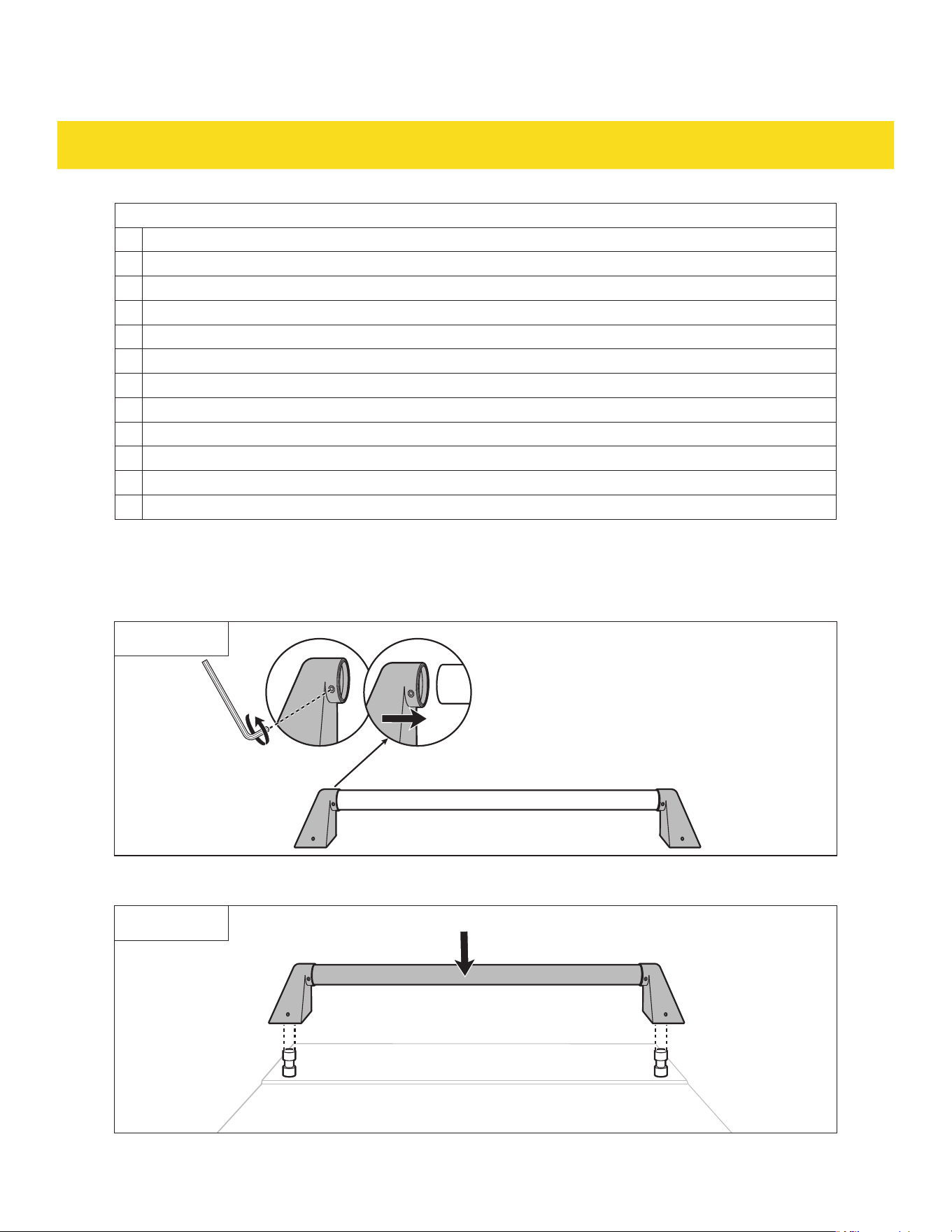
3.3 Install the handle
1. Attach door side brackets (2) to both ends of the door handle (1) (Fig. 5).
Fig. 5
2. Place the assembled door handle (1) onto the door pins on the oven door (33) (Fig. 6).
Fig. 6
24
INSTALLATION
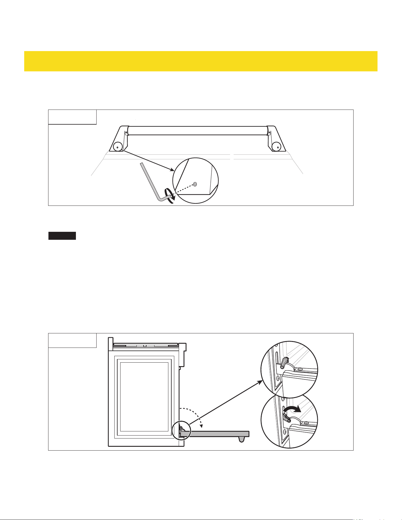
3. Tighten the pre-installed screws on the door side brackets (2) with the hex key (3) (Fig. 7). Do not
overtighten the screws.
Fig. 7
3.4 Attach/detach the oven door
NOTICE
The oven door (33) has multiple colors available (sold separately). Visit Thor kitchen website for
further details.
•
The oven door (33) may be too big or heavy. It is recommended to have 2 people work together for
attaching/detaching the oven door.
•
Do not carry or hold the removed oven door (33) by the door handle. It cannot support the weight of
the oven door (33).
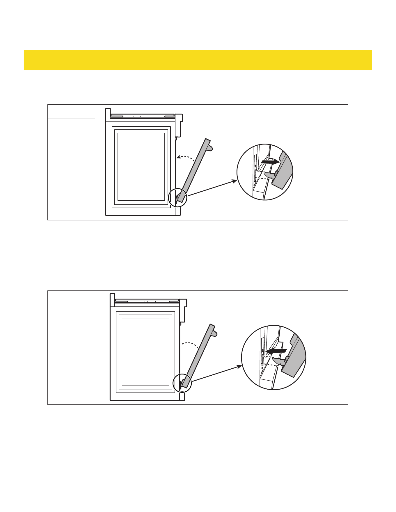
Detach
1. Fully open the oven door (33).
2. Unlock the hinge lock on both sides by rotating them fully towards the oven door (33) (Fig. 8).
Fig. 8
3. Firmly grasp both sides on the oven door (33).
25
INSTALLATION
4. Close the oven door (33) until it is approximately at a 20° angle (Fig. 9). When the oven door (33) is at
the correct angle position, the hinges arms release from the appliance.
20°
Fig. 9
5. Take out the oven door (33) by lifting it upwards and outwards.
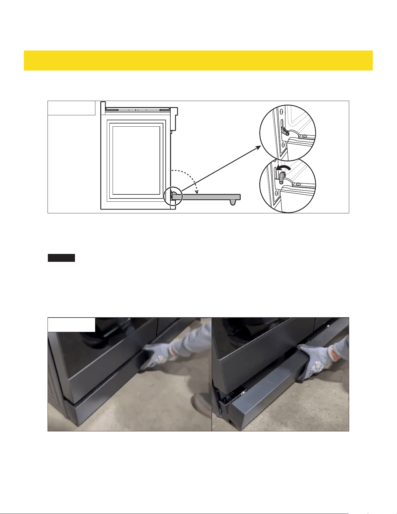
Attach
1. Firmly grasp both sides on the oven door (33).
2. With the door at the same 20° angle as the detach position, slide the hinge arms into the bottom edge
of the hinge slots on the appliance (Fig.10).
20°
Fig. 10
3. The notch in the hinge arms must be fully inserted into the bottom edge of the slots.
4. Open the door fully. If the door does not open fully, the hinge arms are not inserted correctly in the
bottom edge of the hinge slots.
26
INSTALLATION
5. Re-engage the hinge locks, rotating them back toward the slots in the oven (Fig.11).
Fig. 11
6. Close the oven door (33).
3.5 Attach/detach the kickplate
NOTICE
The kickplate (37) has multiple colors available (sold separately). Visit Thor kitchen website for
further details.
Detach
1. Tilt the kickplate (37) backwards to release it from the magnets (Fig. 12).
2. Lift the kickplate (37) upwards to unhook it from the sides (Fig. 12).
Fig. 12
27
INSTALLATION
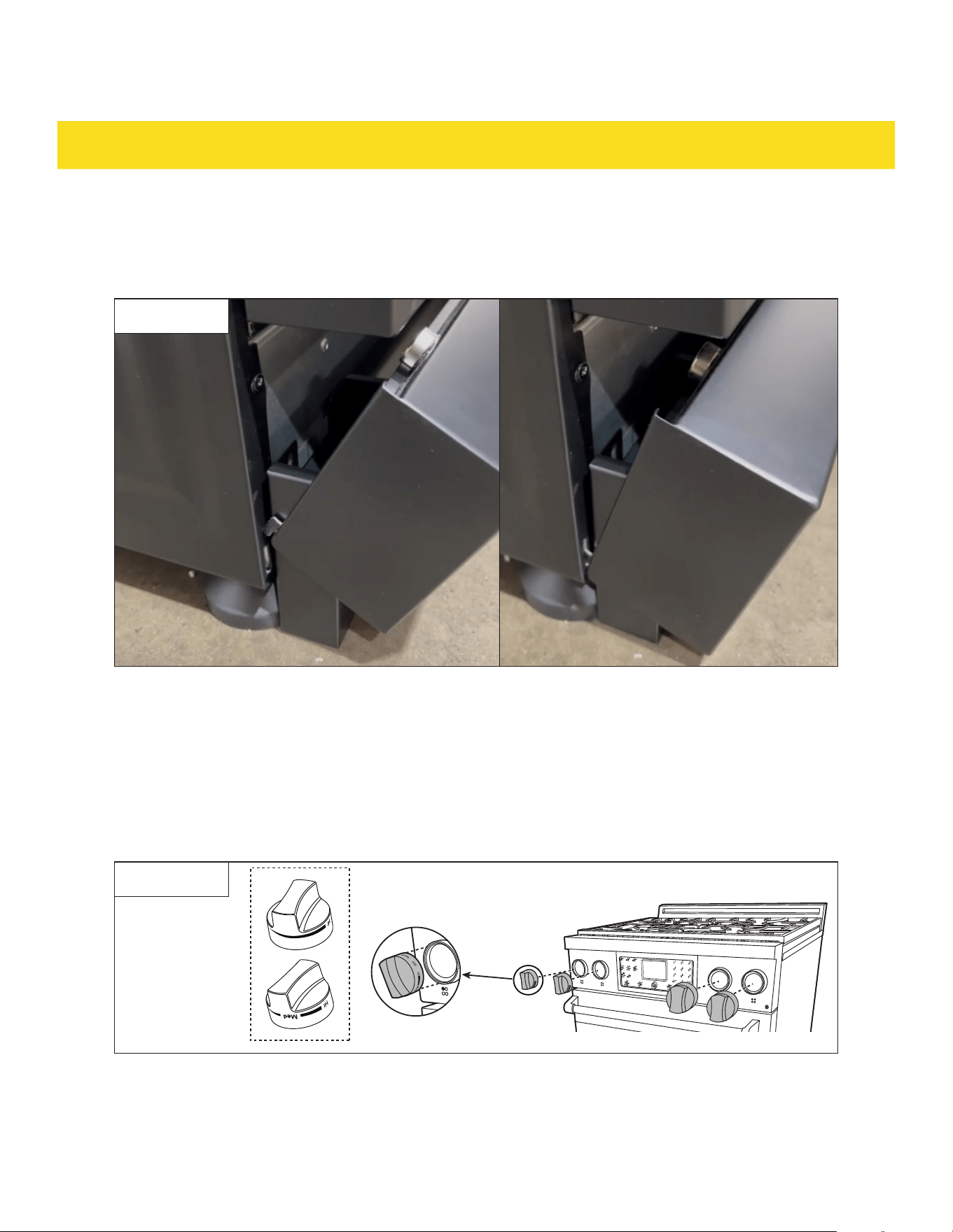
Attach
1. At a tilted angle, hook the kickplate (37) to the slits on both sides of the appliance (Fig. 13).
2. Rotate the kickplate (37) upwards, the magnets snap it into place (Fig. 13).
Fig. 13
3.6 Install the burner knobs
There are markings located on the control panel (29) to show which knob bezel (30) corresponds to which
burner base (15/19)/burner ring (46/47) on the cooktop (31).
1. Match the knobs (35/36) into its corresponding knob bezels (30) (Fig. 14/15).
Gas models (RSG30/LP, RSG36/LP, RSG30B/LP and RSG36B/LP only)
Fig. 14
28
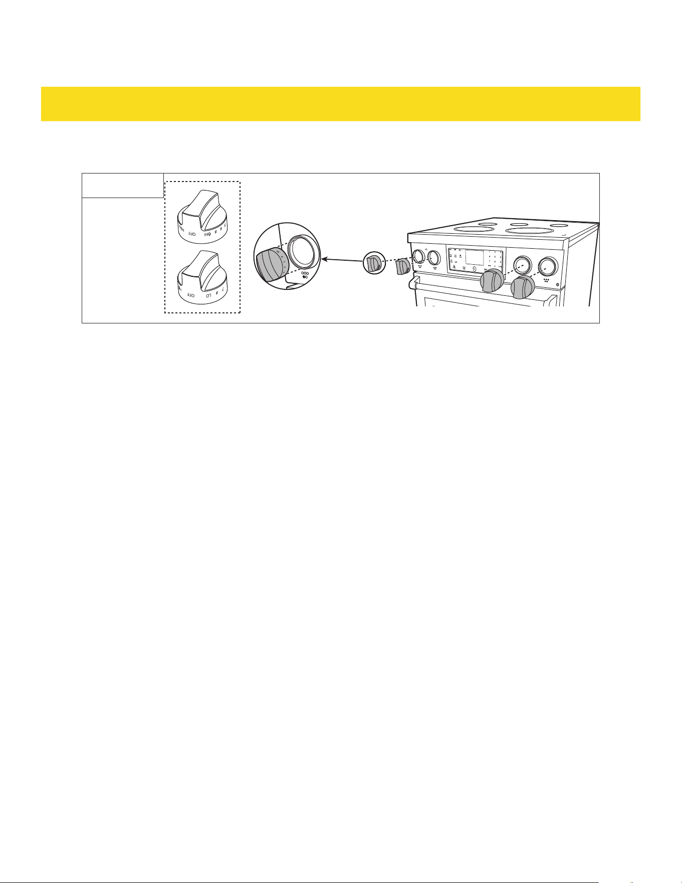
INSTALLATION
Electrical models (RSE30, RSE36, RSE30B and RSE36B only)
Fig. 15
2. Push the knobs (35/36) in fully. Make sure there is no friction between the knobs (35/36) and the bezel
around them.
3.7 Installation for gas models (RSG30/LP, RSG36/LP, RSG30B/LP and RSG36B/LP
only)
NG to LP gas conversion (RSG30/LP, RSG36/LP, RSG30B/LP and RSG36B/LP only)
The appliance is configured for use with NG gas as default. To convert the NG gas configuration to LP gas
configuration, contact the local certified gas technician to complete the conversion. The LP conversion
number for RSG models are:
•
RSG30/B: LPKRSG30
•
RSG36/B: LPKRSG36
29
INSTALLATION
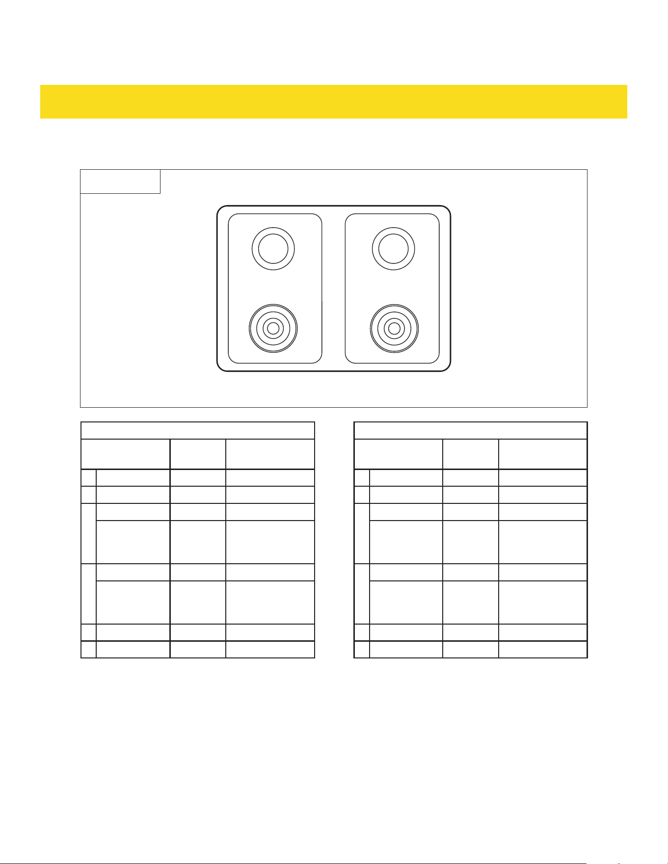
For RSG30/LP and RSG30B/LP:
Front
Left Right
Rear
33
11
44
22
Fig. 16
NG configuration LP configuration
Burner location BTU
Orifice size
(mm)
Burner location BTU
Orifice size
(mm)
1 Rear left 12000 1.50 1 Left rear 12000 1.07
2 Rear right 12000 1.50 2 Right rear 12000 1.07
3
Front left 15000 1.65
3
Front left 15000 1.00
Front left
(small
nozzle)
- 0.38
Front left
(small
nozzle)
- 0.34
4
Front right 15000 1.65
4
Front right 15000 1.00
Front
right (small
nozzle)
- 0.38
Front
right (small
nozzle)
- 0.34
-- Broiler 10000 1.32 -- Broiler 10000 1.05
-- Oven 185000 1.9 -- Oven 18500 1.33
30
INSTALLATION
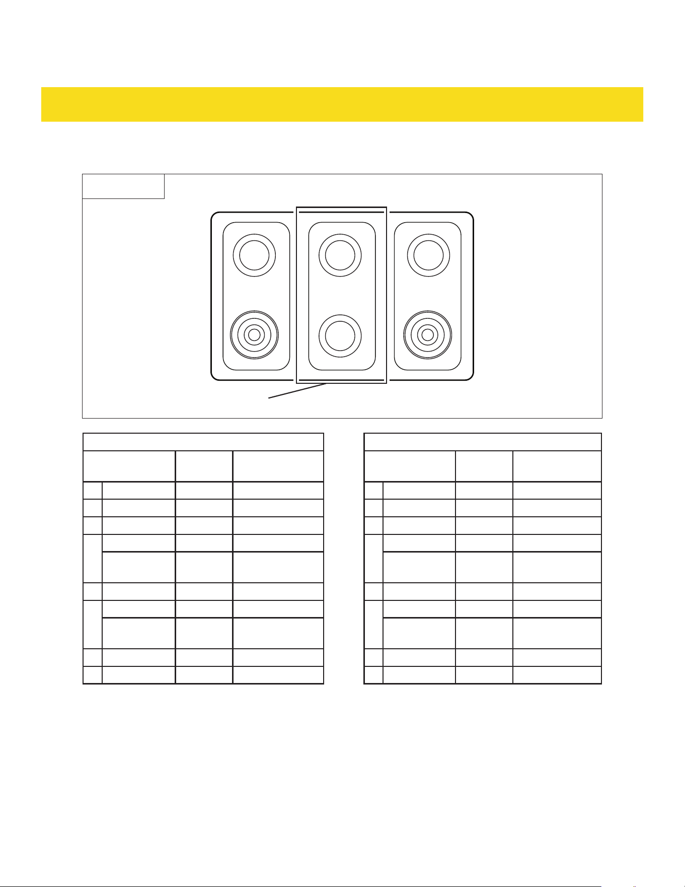
For RSG36/LP and RSG36B/LP:
Front
Left
Middle
Right
Rear
44 55 66
11 22 33
Fig. 17
NG configuration LP configuration
Burner location BTU
Orifice size
(mm)
Burner location BTU
Orifice size
(mm)
1 Rear left 12000 1.5 1 Rear left 12000 1
2 Rear middle 6000 1.06 2 Rear middle 6000 0.6
3 Rear right 12000 1.5 3 Rear right 12000 1
4
Front right 15000 1.65
4
Front right 15000 1.07
Front right
(simmer)
- 0.38
Front right
(simmer)
- 0.34
5 Front middle 18000 1.88 5 Front middle 18000 1.24
6
Front left 15000 1.65
6
Front left 15000 1.07
Front left
(simmer)
- 0.38
Front left
(simmer)
- 0.34
-- Broiler 13500 1.62 -- Broiler 13500 1.05
-- Oven 22000 2.18 -- Oven 22000 1.33
31
INSTALLATION
Connect to a gas supply (RSG30/LP, RSG36/LP, RSG30B/LP and RSG36B/LP only)
•
A manual shut-off valve has to be installed in an accessible location in the gas piping external to the
appliance for the purpose of turning on or shutting off the gas supply to the appliance.
•
During any pressure testing of the gas supply piping system at a test pressure equal to or less than
1/2 psi (3.5 kPa), isolate the appliance from the building's gas supply piping system by closing its
individual manual shut-off valve.
Equipment required
•
Cross-head screwdriver
•
Flat-head screwdriver
•
Pencil
•
Measuring tape
•
Adjustable wrench
•
Pipe wrench x 2
•
Spirit level
•
Gas line shut-off valve
•
Flex gas line rated for NG/LP (1/2" (1.2 mm) NPT
x 1/2" (1.2 mm) I.D.) Must use a new flex gas line
when installing a new appliance.
•
Flare fitting for connection to gas supply
line (1/2" (1.2 mm) NPT x 1/2" (1.2 mm) I.D.)
•
Flare fitting for connection to pressure regulator
on appliance (1/2" (1.2 mm) NPT x 1/2" (1.2 mm)
I.D.)
•
Liquid gas leak detector
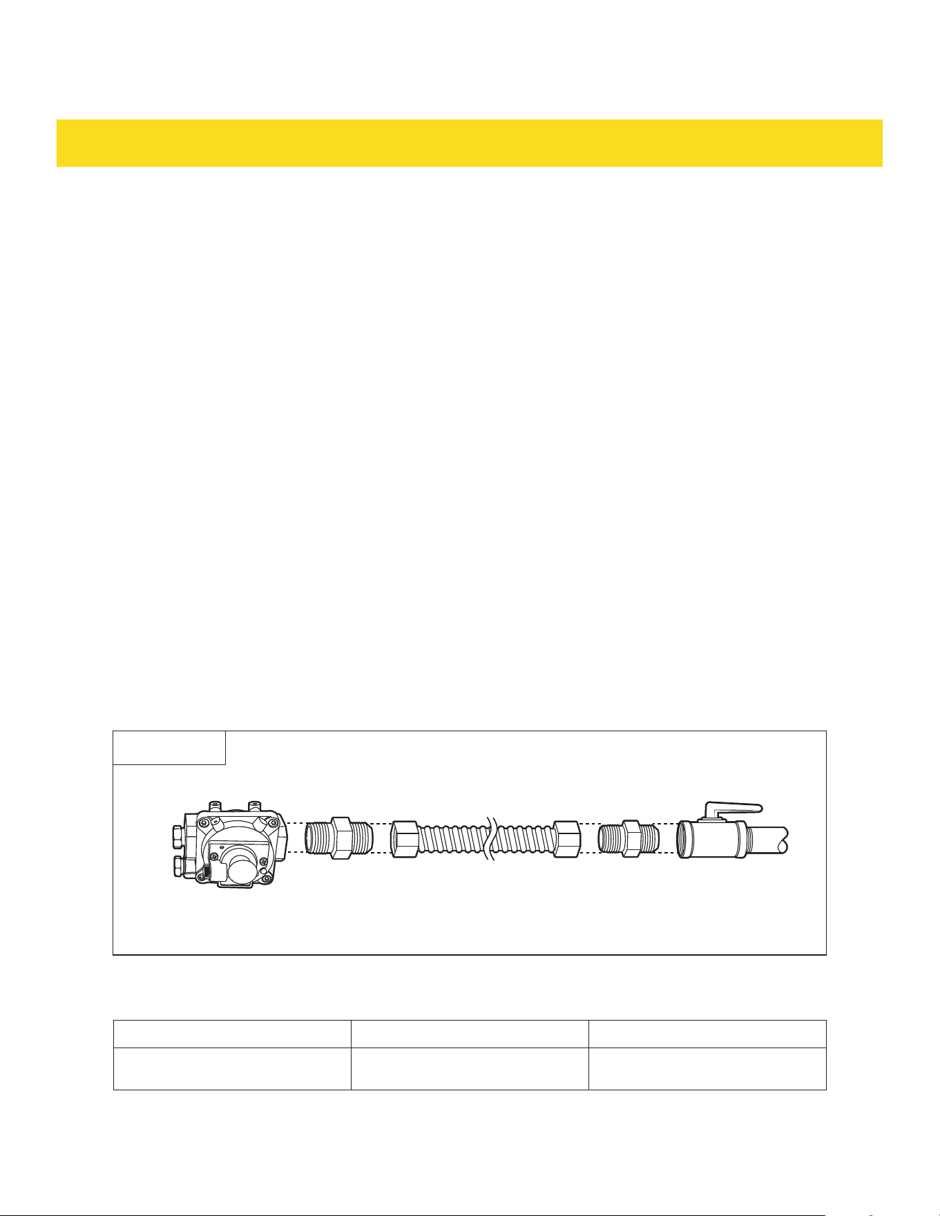
Connect to gas supply
1. Must include a shut-off valve: Install a manual gas line shut-off valve in an easily accessible location.
Do not block access to shut-off valve.
2. Connect the male pipe thread end of the 1/2" flare fitting adapter to the NPT of the pressure regulator
inlet (42) (Fig. 18).
Fig. 18
3. Install a male 1/2" flare fitting to the NPT internal thread of the manual shut-off valve (Fig. 16).
4. Check the gas supply pressure required for the regulator setting:
LP (Liquid Propane) in wc NG (Natural gas) in wc
Appliance pressure regulator
setting for outlet pressure
10.0 5.0
5. Connect the flex gas line to the gas inlet (43) on the appliance and to the shut-off valve, positioning the
appliance to allow for connection.

32
INSTALLATION
6. After making all necessary connections, conduct a leak test of the appliance according to the
manufacturer's instructions (see the following chapter).
Gas leak test (RSG30/LP, RSG36/LP, RSG30B/LP and RSG36B/LP only)
•
Leak testing of the appliance shall be conducted in accordance with these instructions.
1. Ensure that all appliance burner knobs (35/36) are in the off position, and then turn on the main gas
supply valve.
2. Use a liquid gas leak detector to check all gas connection joints and fittings for leaks in the system.
Gas leaks may not be detected by smell alone. Never use an open flame to check for gas leaks.
3. Wipe off the liquid gas leak detector after the test.
3.8 Electrical connection for gas range (RSG30/LP, RSG36/LP, RSG30B/LP and
RSG36B/LP only)
•
This appliance must be supplied with the proper voltage and frequency, and connected to an individual
properly grounded branch circuit, protected by a circuit breaker or fuse having amperage as specified
on the rating label. The rating label is located on the right of the oven door (33).
•
The outlet for the appliance should be located within the range of the appliance's power cord. Do not
use an extension cord with this appliance.
•
If the electrical service provided does not meet the above specifications, have a licensed electrician
install an approved outlet.
•
It is recommended to have the electrical wiring and hookup of the appliance connected by a qualified
electrician. After installation, have the electrician explain where and how to locate and disconnect the
appliance from power.
WARNING
Electrical Grounding Instructions
This appliance is equipped with a three-prong grounding plug for your protection against shock hazard
and should be plugged directly into a properly grounded outlet. Do not cut or remove the grounding prong
from this plug.
Connect the plug
1. Check that all burner knobs (35/36) are at the OFF position.
2. Connect the plug (40) to a suitable outlet. The control panel (29) flashes once and a beep tone plays.

33
INSTALLATION
3.9 Electrical connection for electric range (RSE30, RSE36, RSE30B and RSE36B
only)
•
This appliance must be supplied with the proper voltage and frequency, and connected to an individual
properly grounded branch circuit, protected by a circuit breaker or fuse having amperage as specified
on the rating label. The rating label is located on the right of the oven door (33).
•
This appliance is manufactured ready to be installed with a single phase 4-wire power supply cord
rated at 240 Volt, 50 Amps, rated at 194 °F (90 °C).
•
This appliance can only be plugged into a standard 14-50R wall receptacle, Be sure the wall
receptacle is within reach of range's final location.
•
It is recommended to electrically ground the appliance during installation in accordance with local
codes or, in the absence of local codes, with NFPA 70 or CSA C22.1.
•
If the electrical service provided does not meet the above specifications, have a licensed electrician
install an approved outlet.
•
It is recommended to have the electrical wiring and hookup of the appliance connected by a qualified
electrician. After installation, have the electrician explain where and how to locate and disconnect the
appliance from power.
•
Effective January 1,1996, the National Electrical Code requires that new constructions (not pre-
existing) utilize a 4-conductor connection with an electric appliance. When installing an electric
appliance in new construction, follow the 4-wire connection section of this chapter.
•
The outlet for the appliance should be located within the range of the appliance's power cord. Do not
use an extension cord with this appliance.
Equipment required
•
Cross-head screwdriver
•
3 or 4 prong UL or CSA International Certified power cord (rated at 240 Volt, 50 Amps)
4-wire connection
1. Loosen the screws on the terminal block cover (52) and set the screws aside for later use.
2. Identify the corresponding terminals on the terminal block (50) for each power cord wire: live (L1),
live (L2), neutral (N), and ground (G).
34
INSTALLATION
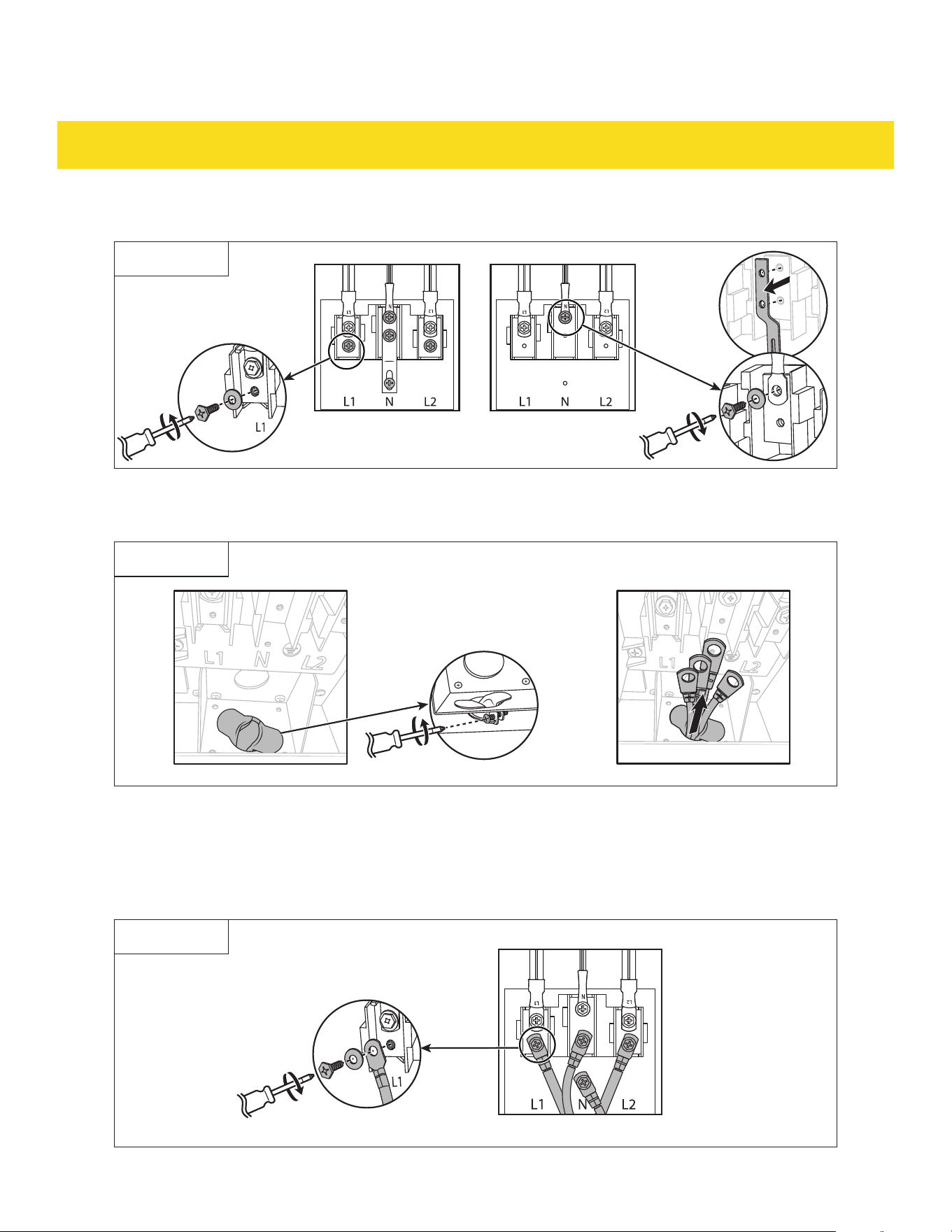
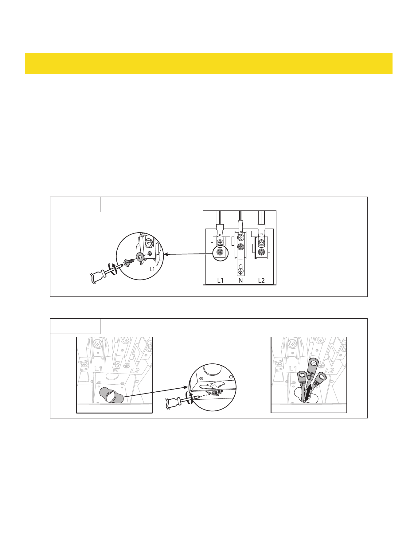
3. Remove the 4 lower terminal screws from the terminal block (50) (Fig. 19).
Fig. 19
4. Remove the 2 upper screws of the neutral (N) terminal and take out the grounding strip (Fig. 19).
5. Re-tighten the 2 upper screws of the neutral (N) terminal (Fig. 19).
Fig. 20
6. Loosen the screws on the strain relief (51) (Fig. 20).
7. Extend the power cord wire upwards through the strain relief (51) from the bottom of the back panel
(Fig. 20).
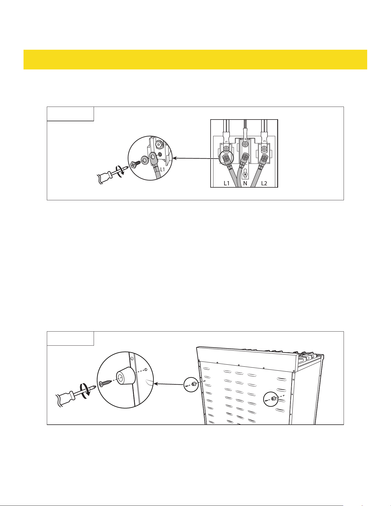
8. Hook the ring terminals of the power cord wire into their designated terminals on the terminal
block (50) (e.g., live 1/2, neutral, and ground) and tighten the screws securely (Fig. 21).
Fig. 21
35
INSTALLATION
9. Ensure the ring terminals have good contact with the terminals on the terminal block (50).
10. Slightly push the power cord upwards to leave some slack above the strain relief (51), then tighten the
screws on the strain relief (51).
11. Reinstall the terminal block cover (52) and re-tighten the screws.
3-wire connection
1. Loosen the screws on the terminal block cover (52) and set the screws aside for later use.
2. Identify the corresponding terminals on the terminal block (50) for each power cord wire: live (L1),
live (L2), and neutral (N).
3. Remove the 3 lower terminal screws (L1, L2, and N) from the terminal block (50) (Fig. 22).
Fig. 22
4. Loosen the screws on the strain relief (51) (Fig. 23).
Fig. 23
5. Extend the power cord wire upwards through the strain relief (51) from the bottom of the back panel.
36
INSTALLATION
6. Hook the ring terminals of the power cord wire into their designated terminals on the terminal
block (50) (live 1/2 and neutral) and tighten the screws securely (Fig. 24).
Fig. 24
7. Ensure the ring terminals have good contact with the terminals on the terminal block (50).
8. Slightly push the power cord upwards to leave some slack above the strain relief (51), then tighten the
screws on the strain relief (51).
9. Reinstall the terminal block cover (52) and re-tighten the screws.
Connect the plug
1. Check that all burner knobs (35/36) are at the OFF position.
2. Connect the plug to a suitable outlet. The control panel (29) flashes once and a beep tone plays.
3.10 Install the back spacers
1. Locate the 2 spacer holes (41) at the back of the appliance (Fig. 25).
2. Attach the spacers (6) with the spacer screws (7) (Fig. 25).
Fig. 25
37
INSTALLATION
3.11 Move and level the appliance
•
It is recommended to use a furniture dolly when moving the appliance to prevent damaging the floor.
•
If the appliance is too heavy, it is possible to remove the oven door (33) before moving the appliance.
•
The appliance must be installed by a professional to ensure that the appliance is level. Improper
installation or failure to adjust the level may cause the telescopic rack (8b) to slide out naturally due to
tilt and cause personal injury.
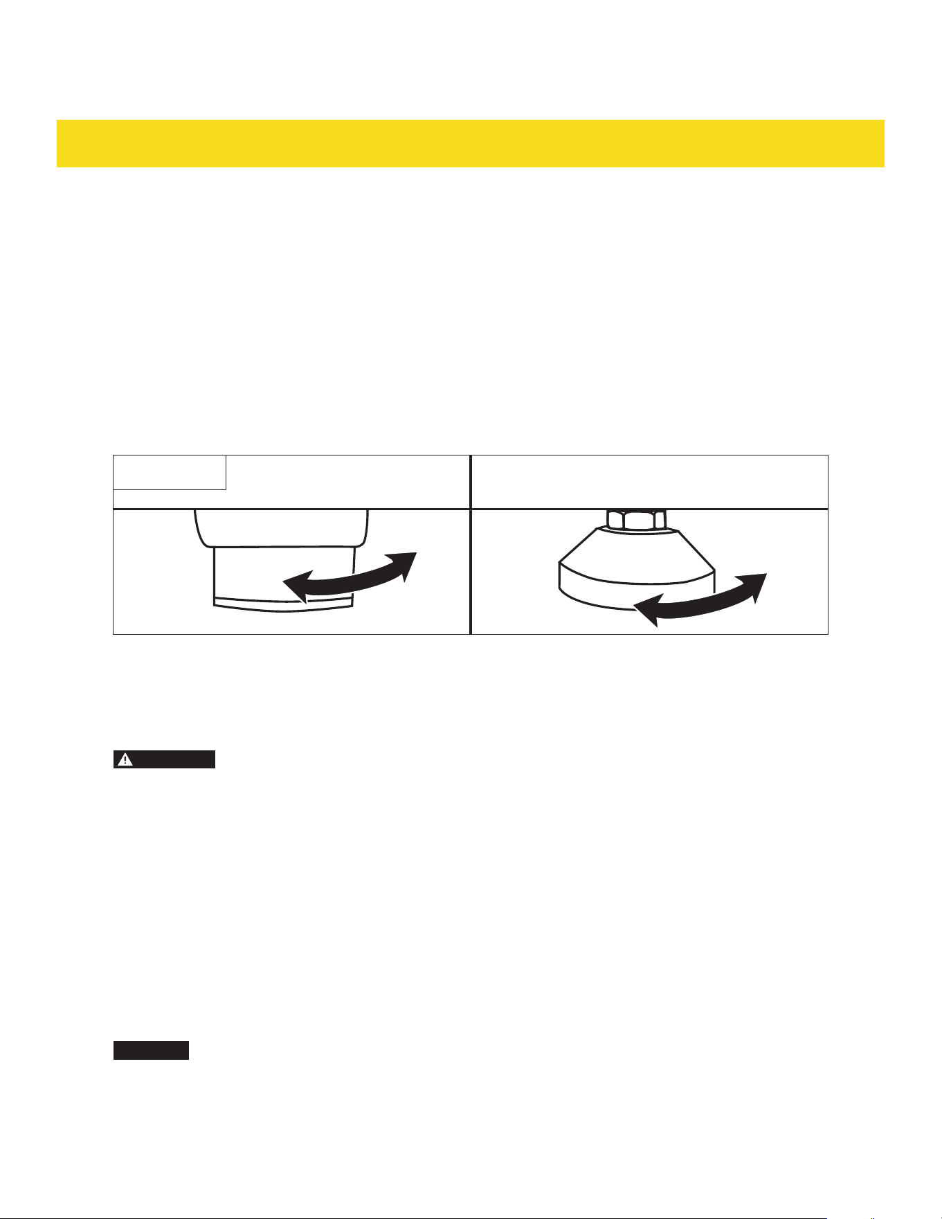
1. Adjust the height of the appliance to fit the countertops following the clearances information provided
in chapter 3.2 Clearances and dimensions.
2. Rotate the feet (39) clockwise to increase the height of the feet (39) (Fig. 26).
3. Rotate the feet (39) counter-clockwise to decrease the length of the feet (39) (Fig. 26).
Fig. 26
4. Use a spirit level to check for adjustments. Place the spirit level on the oven rack (8) for more
accuracy.
3.12 Install anti-tip device
WARNING
Risk of injury!
•
A child or adult can tip the appliance and be killed.
•
Install the anti-tip device to the wall/floor. Verify the anti-tip device has been properly installed and
engaged with the back of the appliance.
•
Engage the appliance to the anti-tip device (4) by pushing the appliance all the way into the installation
location. Ensure the anti-tip device (4) is re-engaged when the appliance is moved.
•
Re-engage the anti-tip device (4) if the appliance is moved. Do not operate the appliance without the
anti-tip device (4) in place and engaged.
•
See installation instructions for details.
•
Failure to do so can result in death or serious burns to children or adults.
•
Even after the anti-tip device (4) is installed, do not step, lean or sit on the oven door (33) or place any
heavy objects on it.
CAUTION
Risk of damage! Do not drill into any pipes or power lines beneath the surface while
preparing the mounting holes for the anti-tip device (4). Use a voltage/metal detector before
drilling any holes to eliminate any such potential risks.
38
INSTALLATION
Equipment required
•
Power drill
•
Pencil
•
Spirit level
•
Measuring tape
For RSG30/LP and RSG30B/LP
1. Place the anti-tip device (4) on the floor, on the right side of the installation area.
2. Test the fit of the anti-tip device (4) by pushing the appliance into place. Ensure that the anti-tip
device (4) catches onto the back right foot (39) of the appliance.
3. Once the correct placement is verified, pull out the appliance and mark the holes on the anti-tip
device (4) onto the floor (Fig. 27).
4. Put away the anti-tip device (4) and drill holes on the marked positions (Fig. 27).
Fig. 27
5. Attach the anti-tip device (4) to the floor using the provided anti-tip device screws (5) (Fig. 28).
Fig. 28
6. Push the appliance all the way into the installation location, engaging it firmly with the anti-tip
device (4).
39
INSTALLATION
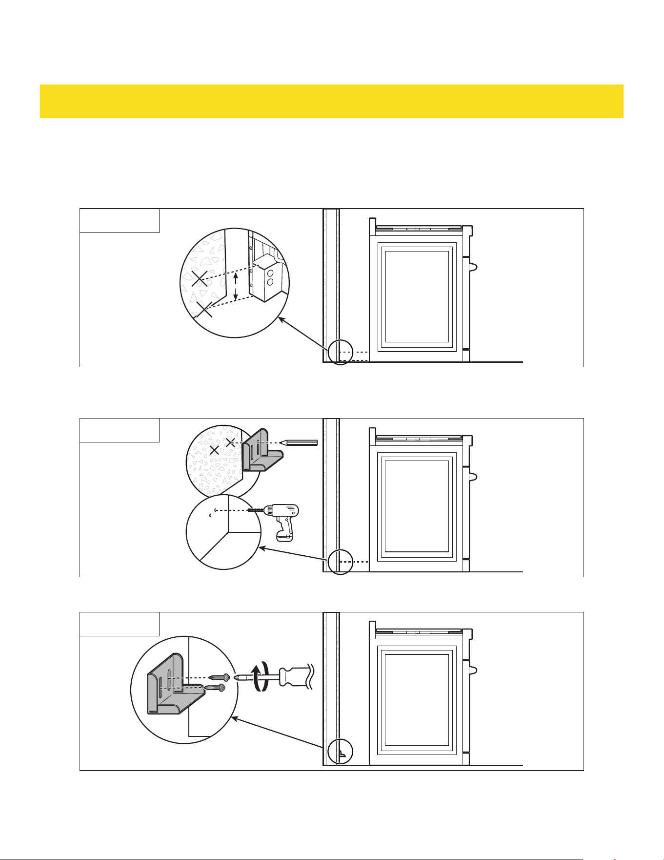
For RSG36/LP, RSE30 , RSE36, RSG36B/LP, RSE30B and RSE36B
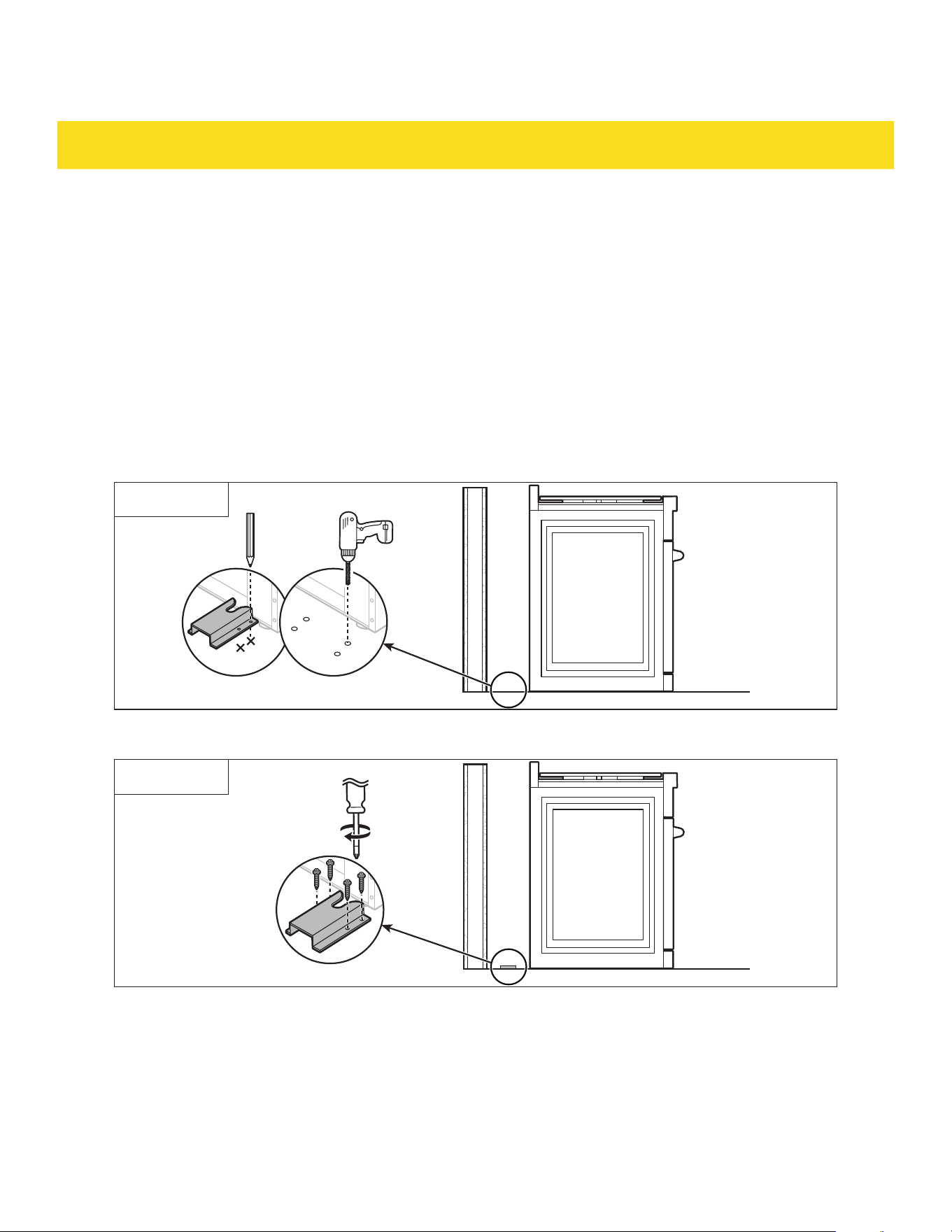
1. Measure the height between the floor and the left side of the back panel (Fig. 29).
2. Mark this measurement on the back wall (Fig. 29).
Fig. 29
3. Place the anti-tip device (4) against the wall and mark the holes on it, ensuring they are level (Fig. 30).
4. Drill holes on the marked places (Fig. 30).
Fig. 30
5. Attach the anti-tip device (4) to the back wall using the provided screws (5) (Fig. 31).
Fig. 31
6. Push the appliance all the way into the installation location, engaging it with the anti-tip device (4).
40
INSTALLATION
Check the installation of the anti-tip device
1. Remove any items on the cooktop (31).
2. Grasp the top rear edge of the appliance and carefully attempt to tilt it forward.
3. Verify that the anti-tip device (4) is engaged.
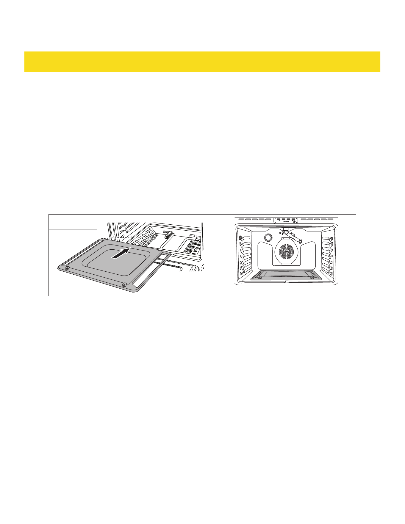
3.13 Place the bottom cover (RSG30/LP, RSG36/LP, RSG30B/LP and RSG36B/LP
only)
•
To avoid permanent damage to the oven bottom finish, do not line the oven bottom with any type of foil
or liner.
Place the oven bottom cover (34) over the oven bottom assembly (26). When placed correctly, the rim of
the oven bottom cover (34) fully fits into the indentation of the oven bottom assembly (26) (Fig. 32).
Fig. 32
41
INSTALLATION
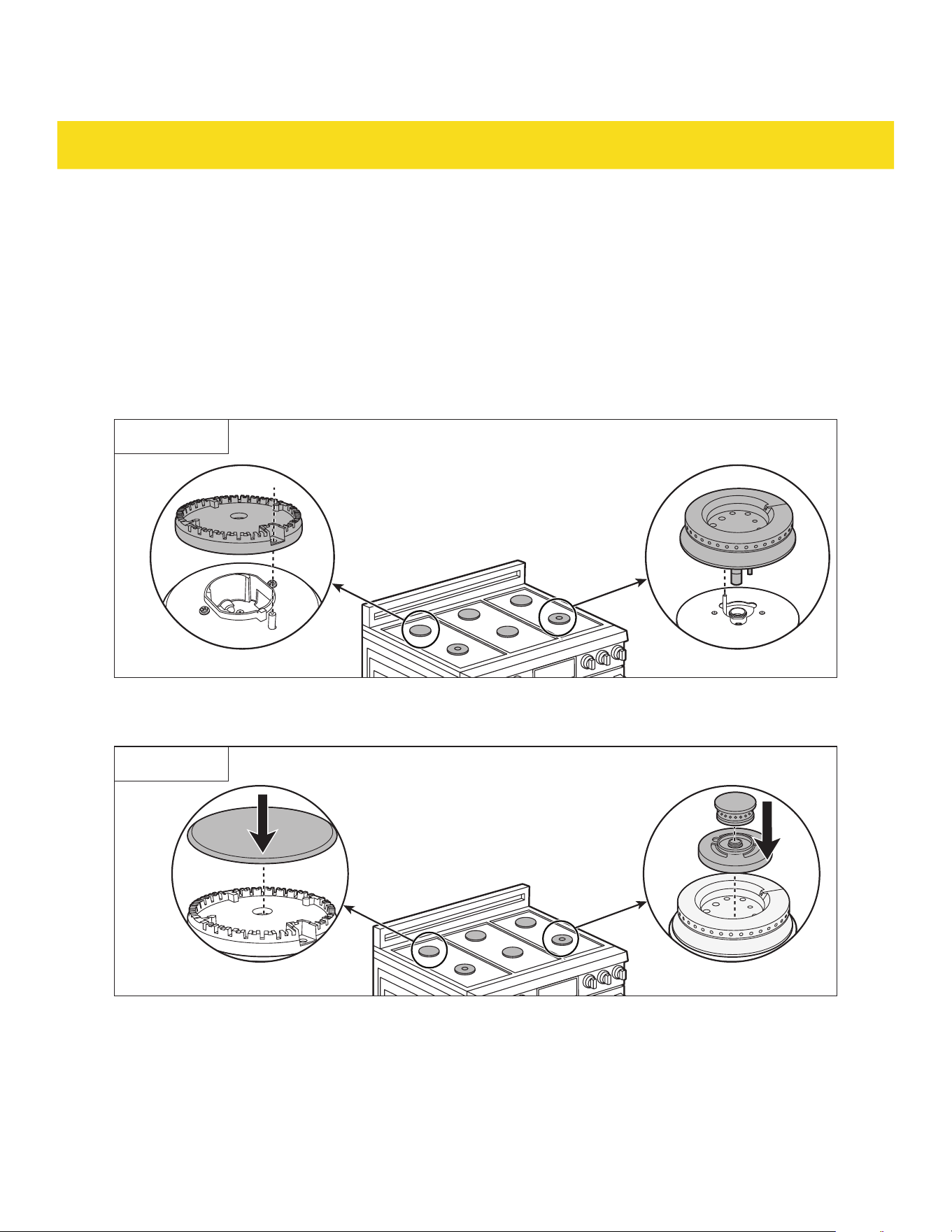
3.14 Assemble the burners
•
The burner parts (13, 14, 16, 17, 18) come pre-assembled and taped to the cooktop (31).
•
If adhesive residue remains, use a soft cloth and dishwashing liquid to remove it. Avoid harsh or
abrasive cleaners.
•
The burner base (15/19) has an electrode that fits into holes on the burner head (14)/bass flame
spreader (18). Ensure the hole in the burner head (14)/dual burner lower flame spreader (18) is
positioned over the electrode (Fig. 33) when assembling.
•
Properly assembled burners should have a level surface and not be tilted (Fig. 33). A tilted burner may
cause an uneven flame.
Fig. 33
•
For RSG36/LP and RSG36B/LP, match the correct sizes of burner heads (14) and burner caps (13) to
the burner base (15) (Fig. 34).
Fig. 34
•
For RSG30/LP, RSG36/LP, RSG30B/LP and RSG36B/LP place the cooktop grates (28) on the
cooktop (31) after assembling the burners.
42
INSTALLATION
3.15 Perform a test run
Check burner ignition (RSG30/LP, RSG36/LP, RSG30B/LP and RSG36B/LP only)
1. Select a burner knob (35/36) and simultaneously push in and turn to the Ignite position. A clicking
sound indicates proper ignition operation.
2. The burner should ignite within 4 seconds once the air is purged from the supply lines. After ignition,
rotate the burner knob (35/36) out of the Ignite position.
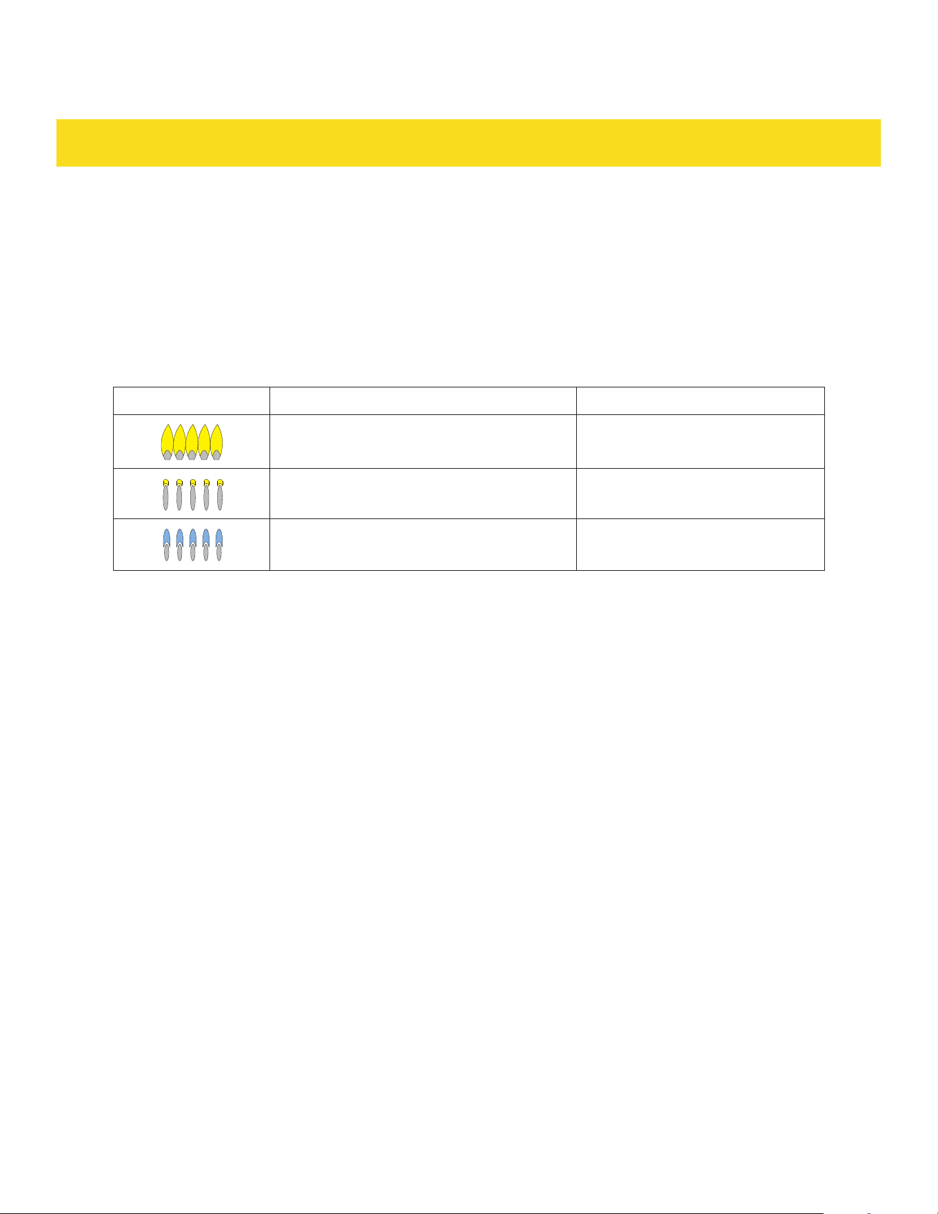
3. Visually check the combustion quality of the flames:
Flame appearance Description Verdict
Yellow flames Call for service to adjust the flame
Yellow tips on the outer cones Normal for LP
Soft blue flames Normal for NG
4. Test each burner one by one until all burners have been checked.
Check oven and broiler burners/heating elements
1. Select BAKE function.
2. Press START. After 30-90 seconds check that the oven burner (26) has started to heat up.
3. Select BROIL HI function.
4. Press START. After 30-90 seconds check that the broiler burner (24) has started to heat up.
3.16 Conditioning
Conditioning burns off any manufacturing residues.
1. Place all the oven racks (8) inside the oven cavity (20).
2. If a hood is installed, set it on high.
3. Set the oven to the BAKE function and preheat the empty oven to 350 °F (176 °C) and allow it to heat
for 30 minutes, then increase the temperature to 500 °F (260 °C) then allow oven to heat for another
30 minutes.
4. Let the oven cavity (20) cool down.
5. Once cooled, wipe the oven cavity (20) with a damp cloth and mild detergent, then dry thoroughly.

43
TROUBLESHOOTING
Problem Possible cause Solution
The appliance is not
level.
The appliance has been installed
improperly.
Place the oven rack (8) in the center of the
oven. Place a level on the oven rack (8).
Adjust the feet (39) until the oven rack (8)
is level. Ensure the floor is level and strong
and stable enough to adequately support the
appliance.
The floor is sagging or sloping. Contact a carpenter to correct the situation.
The kitchen cabinets are not
properly aligned and make the
appliance appear to be not level.
Ensure the cabinets are square and provide
sufficient room for installation.
The appliance must
be accessed for
servicing and cannot
be moved easily.
The kitchen cabinets are not
square and too close to the
appliance.
Contact a builder or installer to make the
appliance accessible.
Carpet is interfering with
movement of the appliance.
Provide sufficient space so the appliance can
be lifted over the carpet.
WARRANTY
Warranty&Service
This appliance has been manufactured by Thor International, 4651 E Airport Drive, California 91761
For Customer Service, please call (877) 288 - 8099
For the most up to date warranty and service policy, please refer to our website
WWW.THORKITCHEN.COM/WARRANTY-REGISTRATION
For in-warranty service requests, please visit our website at
WWW.THORKITCHEN.COM/SERVICE
Please Note: You must provide proof of purchase or installation date for any in-warranty service requests

#ChefInspired
WELCOME TO THE
GORDON RAMSAY COLLECTION
THOR Kitchen x Gordon Ramsay Collection is backed by a solid two-year warranty
on both parts and labor. It’s our commitment to quality and your peace of mind.
Registering your appliance ensures top-notch service and personalized support.
Your registration helps us stay informed about your appliance, enabling us
to provide timely maintenance reminders, updates, and exclusive offers. This
ensures your appliance maintains peak performance for years to come.
01
02
03
Scan the QR Code or visit thorkitchen.
com/register-your-product.
Input your purchase and product
information and select register.
That’s it. You’re all set.
Start cookin’!
ThorKitchen.com/Gordon-Ramsay-Collection