20
SERVICE CENTRE
AUTHORISED RETAILER
1
10
INSTRUCTIONS, USE AND MAINTENANCE MANUAL
Ver. 001 02/2023
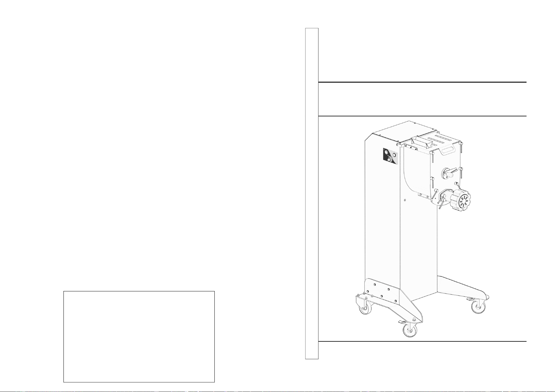
Fresh pasta machine
2
CONTENTS
1. Delivery and warranty 3
1.1 Foreword
1.2 Preserving and using the manual
1.3 Warranty
1.4 Description of the machine
1.5 Permitted use
1.6 Improper use - not permitted use
1.7 Identification of the equipment
1.7.1 Warning plates
1.8 Safety devices and protections
1.9 Operating station
2. Technical features 9
2.1 Main components
2.2 Technical specifications
2.3 Dimensions and weight of the machine
2.4 Noise level
2.5 Electrical diagrams
2.5.1 230V / 60 Hz 1 ph
3. Controls and indicator lights 12
3.1 List of controls and indicator lights
4. Inspection, shipping, delivery and installation 13
4.1 Inspection
4.2 Shipping and handling the machine
4.3 Installation
4.3.1 Disposing of the packaging
4.3.2 Handling the machine
4.4 Electrical connections
4.4.1 Single-phase machine
5. Start up and shut down 14
5.1 Checking the electrical connections
5.2 Checking the presence and effectiveness of safety devices and guards
5.3 Checking the effectiveness of the emergency button
5.4 Machine start up
5.5 Machine shut down
6. Using the machine 15
6.1 Instructions
6.2 Dough preparation
6.3 Extrusion
7. Maintenance 15
7.1 Lubrication
7.2 Cleaning the machine
7.3 Removing the locking ring, extruder, spiral and cleaning the spout
7.3.1 Extruder maintenance
7.3.2 Removing the tank
7.3.3 Reassembling the tank
8. Trouble-shooting 19
8.1 Trouble-shooting
19
Problem
Cause Solutions
The machine
does not start up
The differential switch is positioned
to “0”.
Bring the switch to “I” position
The main switch is positioned to “0” Bring the switch to “I” position
The start up button is faulty
Contact the Technical
Assistance
Safety devices not present or
incorrectly mounted
Check the safety devices and
protections
The dough does
not flow out
The extruder is dirty Clean the extruder
The machine is running in mixing
mode
Shut down the machine and
push the extruding mode
button
8 - Trouble-Shooting
8.1 - Trouble-shooting
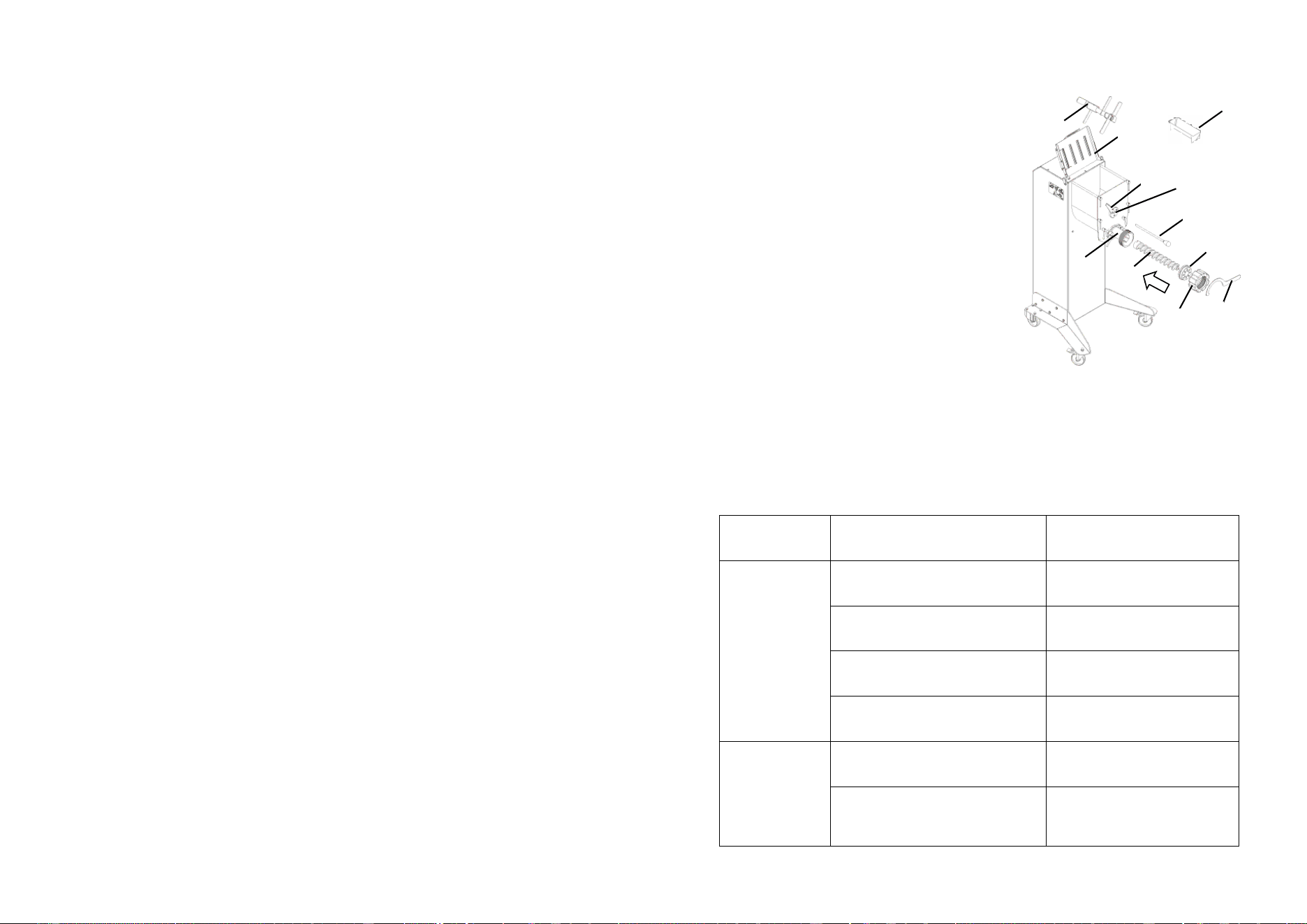
Reassembling the spiral
Insert the screw ref. 9 inside the dough outlet
ref. 11, pushing it all the way, paying attention
that the seat in the rear part of the spiral mates
correctly with the drive pin inside the tank. In-
sert the extruder ref. 8 on the pin on the spiral,
then screw the ring nut ref. 7 by turnin it clo-
ckwise with the aid of the key ref. 6.
Reassembling the blade
Insert the blade ref. 5 inside the tank, positio-
ning it in line with the flange ref. 18 placed on
the front of the tub. Keeping the blade statio-
nary in position with one hand, insert the bar
ref. 4 inside the flange and through the blade
until it stops. Then turn the lever ref. 3 until it is
positioned horizontally.
N.B: Make sure that the lever rif. 3 is correctly
recessed in the seat in the bar ref. 4. If not,
push or pull the bar towards you until you find the correct alignment to tighten the
lever ref. 3. Then close the lid ref. 2 so that it rests on the tank. Now reassemble
the liquid dosing tank ref. 1.
Fig. 7.3.8
5
2
3
4
7
9
8
6
1
11
18
18
Fig. 7.3.5
15
16
Fig. 7.3.7
10
11
17
Fig. 7.3.6
2
13
14
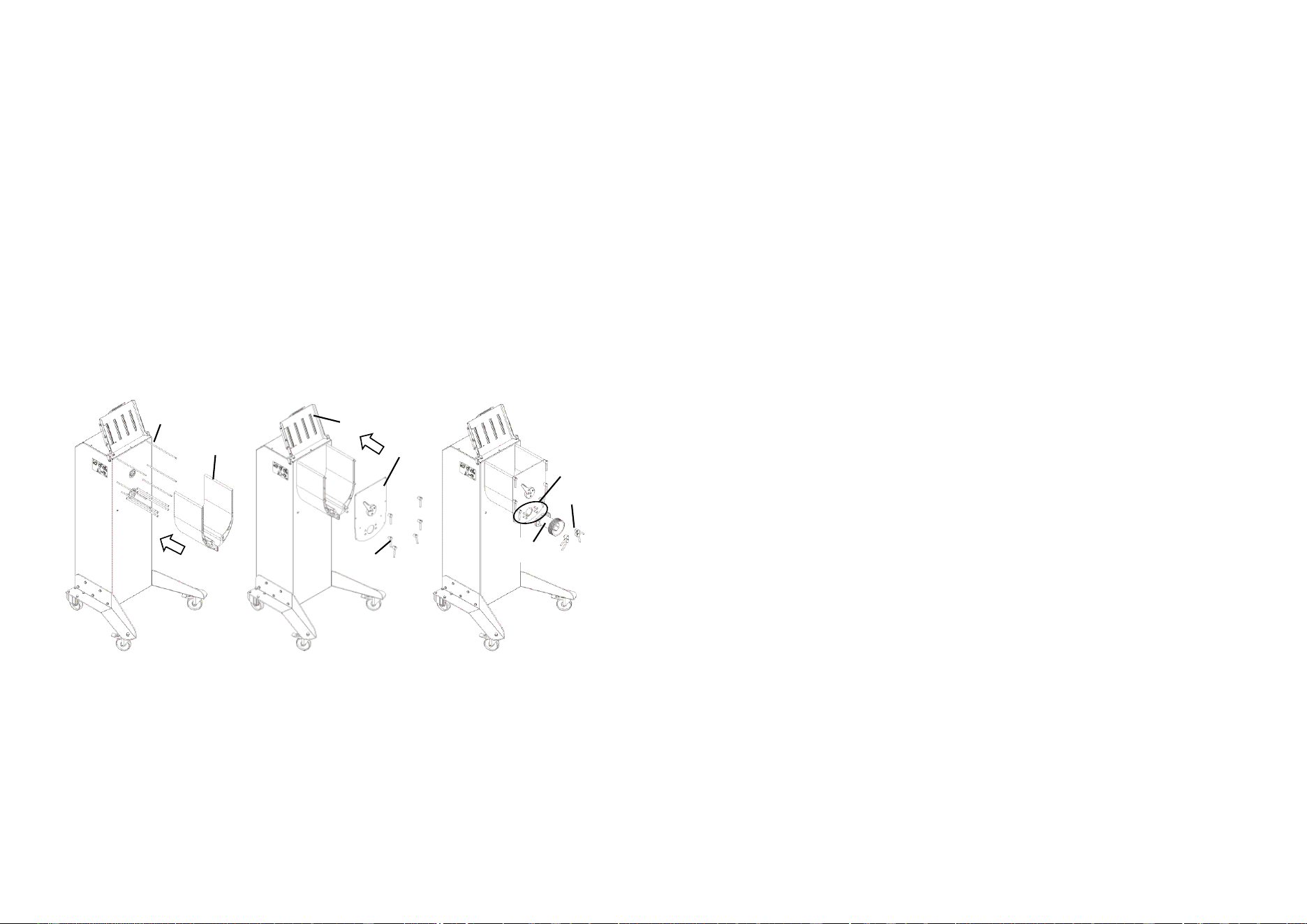
7.3.3 - Reassembling the tank
These are the operations to be carried out for the correct reassembly of the tank.
Reassembling the tank
After having correctly centered the tank ref. 15 with the 10 pins ref. 16, with two
hands push it linearly into place until it is completely in contact with the hull.
Reassembling the front panel
To refit the front panel ref. 14 after having correctly centred it with the 10 pins ref.
16, holding it still with one hand, push it against the tank ref. 15, then lock it to it by
screwing all the eight knobs ref. 13.
Reassembling the dough outlet
To reassemble the dough outlet ref. 11, align it with the four bars ref. 17, then push
it against the front panel ref. 14 and making sure that there are no gaps between
the two parts, holding the union with one hand, lock everything by screwing the
four bolts ref. 10.
3
1 - Delivery and warranty
1.1 - Foreword
WARNING!
The symbols used in this manual are intended to draw the reader's attention to
points and dangerous operations as regards personnel and operators safety as
well as the risks to damage the machine.
Do not operate the machine unless you are not certain to have understood
properly the meaning of these indications.
WARNING!
For clarity, some illustrations in this Manual show the equipment or parts of it with
the panels or casings removed.
Do not use the machine in such conditions. The machine has to be used only
when all guards are in place.
This manual cannot be reproduced, even partially, without the consent of the
manufacturer and its contents can not be used for purposes not permitted by the
manufacturer.
Any violation of the copyright mentioned above could lead to prosecution under law.
1.2 - Preserving and using the manual
The purpose of this manual is to give the users by means of texts and images the
recommendations and essential criteria related to transport, handling, use and
maintenance of the machine. Read this manual carefully prior to using the
machine.
The Manual must be preserved in a known easily accessible place, available for
consultation whenever required. If the Manual is lost, damaged or becomes
illegible, contact your reseller or directly manufacturer for a copy.
If the equipment concerned changes ownership, the Manual has to be handed
over to the new owner.
This manual reflects the state of the techniques at the moment the machine has
been placed on the market and it doesn't has to be considered obsolete just
because not yet updated according to the new expertise. The manufacturer
reserves the right to update the production and related manuals without updating
the production and the previous manuals, except for special cases. In case of
doubts, please contact the nearest Customer Assistance Service of the
manufacturer.
The manufacturer aims to continuously improve its products.
For this reason, the manufacturer is keen to receive any report or proposal aimed
at improving the machine and / or the manual. The equipment has been delivered
to the user under warranty conditions at the moment of the purchase.
Please contact the manufacturer for further details.
1.3 - Warranty
Under no circumstances the user is allowed to tamper with the machine. In case of
fault refer to your supplier.
Any attempt of the user or unauthorized personnel to disassemble, modify or more
4
generally tamper with any part of the machine will cause the Declaration of
Conformity, it shall void the warranty and will relieved the Manufacturer from
damages caused by such behaviour.
The Manufacturer shall be relieved of all liability in the following situations:
- incorrect installation;.
- improper use of the equipment by inadequately trained personnel;
- use contrary to regulations in force in the country where the equipment is used;
- omitted or poor maintenance;
- use of non-original spares or not specific for the model;
- total or partial non-compliance with these instructions- with spare parts that are
not original or are not specific for the model.
1.4 - Description of the machine
The machine in your possession is a simple, compact, highly efficient and powerful
equipment.
- Since it must be used in food applications, the components were carefully
chosen to provide maximum hygiene.
- The basin is made of electropolished stainless steel.
- The tools are made of stainless steel to ensure durability and maximum hygiene.
- Cast stainless steel spout
- It provides two operation modes: mixing and extruding.
- Maximum mixing capacity 9.8 kg (7 kg flour 2.8 kg egg)
- Pre-arranged for dough-cutter installation.
- Ventilated three-phase motor offering the following advantages:
- consistency, high performance and durability of the motor;
- increases the real operation time due to fewer interruptions.
The version represented in this manual have been built in compliance with UL 763,
CSA C22.2 nr 195, NSF 8 and further modifications.
In case of accident, no responsibility can be charged to the manufacturer if the
machine has been modified, tampered with, if it has been used with the safety
guards removed or for purposes not permitted by the manufacturer.
1.5 - Permitted use
The machine was designed and built for fresh pasta production.
It is to be used in professional environments; the machine operator has to be
specialize din the field and have read and understood this manual. After each
work cycle it is advisable to let the machine rest for a few minutes before
using it again.
17
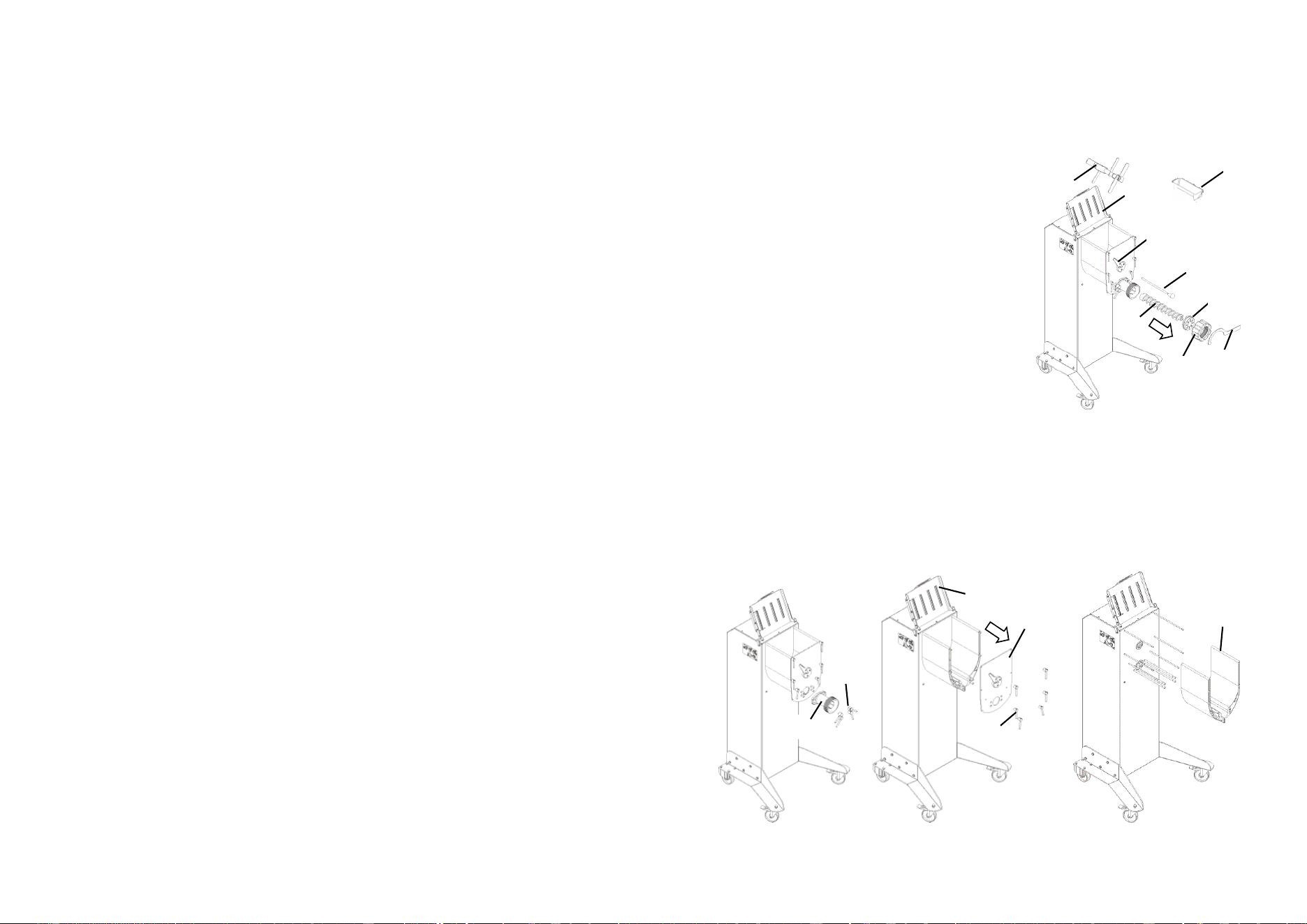
7.3.2 - Removing the tank
At the end of each processing cycle, to better clean the machine, it is also possible
to remove the tank. These are the operations to carry out for a correct disassembly
of the tank.
Removing the blade
Remove the liquid dosing tank ref. 1, lift the cover
ref. 2, rotate the lever ref.3. Take with a hand the
blade ref. 5, remove the bar ref. 4 then lift and
remove the blade ref. 5.
Removing the spiral
Unscrew the ring nut ref. 7 by rotating it counter-
clockwise with the aid of the key ref. 6, remove
the extruder ref. 8 then remove the spiral ref. 9.
Removing the dough otulet
To remove the dough outlet ref. 11, unscrew the
four bolts ref. 10 that kepp it integral with the tub,
then remove it.
Removing the front panel of the tank
To remove the front panel ref. 14, holding it still with on hand, unscrew all the six
remaining knobs ref. 13, the front will then be free to be removed.
Removing the tank
After having carried out all the previous steps correctly, pull the bowl ref. 15
linearly towards you with two hands.
Fig. 7.3.2
10
11
Fig. 7.3.4
15
Fig. 7.3.3
2
13
14
Fig. 7.3.1
5
2
3
4
7
9
8
6
1
16
7.2 - Lubrication
The machine does not require lubrication.
7.3 - Cleaning the machine
WARNING!
Unplug the machine from the mains before cleaning.
Do not wash the machine with pressurized water jet.
With a sponge soaked in water and suitable non toxic neutral degreasers (pH 7),
remove any residues off the machine.
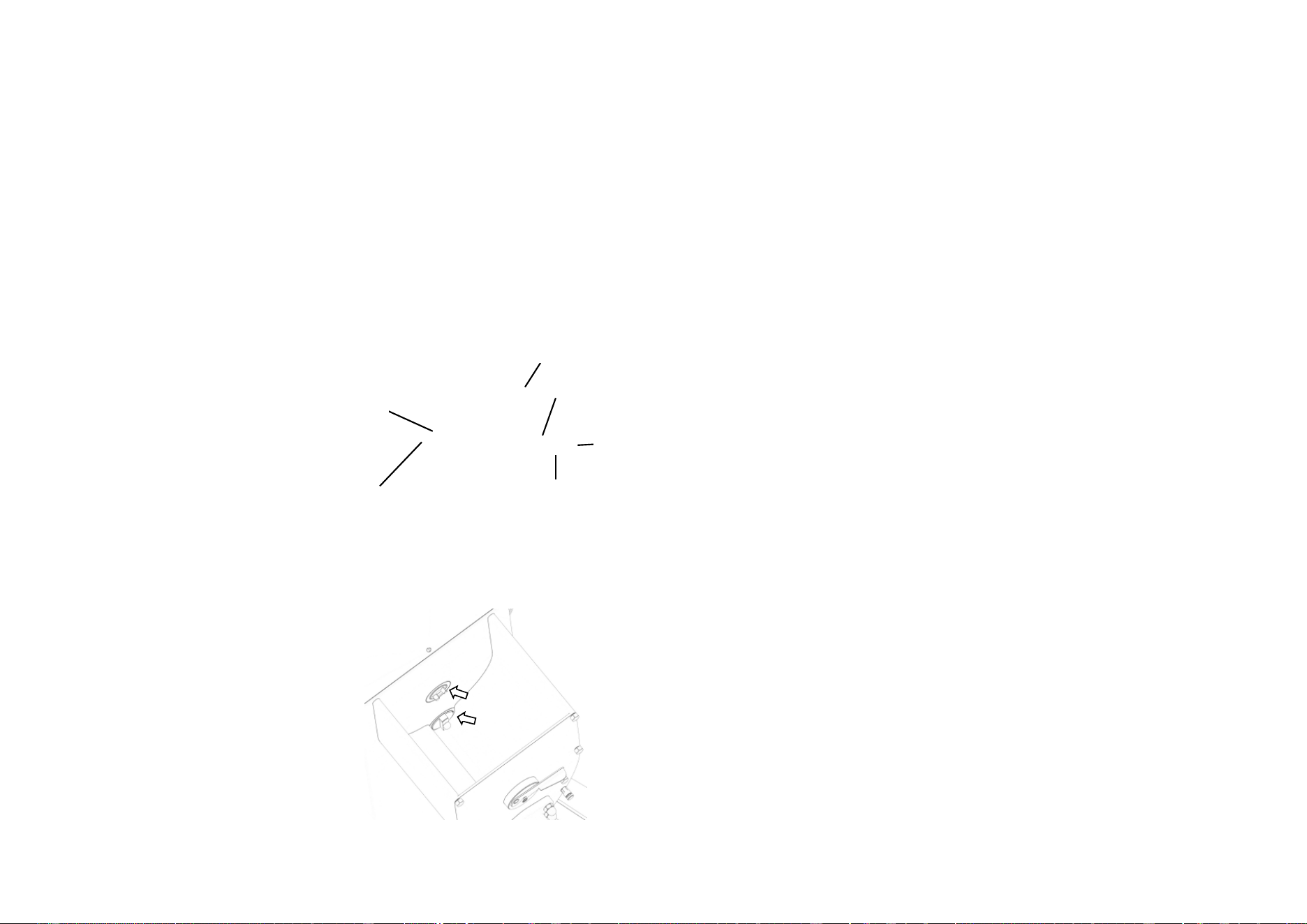
7.3.1 - Removing the tools
At the end of each processing cycle, remove the utensils to optimally clean the
machine.
Removing the mixer blade
1. Put the blade “1” in the position shown in
Fig. 7.2.1.
2. Raise the lever “2” and remove the bar “3”.
3. Remove the blade “1” by sliding it
upwards.
WARNING!
If the blade is not locked in position as shown
in fig. 7.2.1 it cannot be removed.
CAUTION!
If the blade is not lying in the position
shown in Fig. 7.2.1, it cannot be
removed.
Removing the propeller
1. loosen the ring 4
2. remove the die 5
3. remove the spiral 6
WARNING!
After each kneading, ensure the propelling
pivots are thoroughly cleaned so the blade and
Archimedean screw can be properly
assembled (fig 7.2.2)
Fig. 7.2.2
1
Fig. 7.2.1
2
3
5
4
6
5
1.6 - Improper use not permitted
The machine must be used exclusively for the purposes intended by the
manufacturer; in particular:
- do not use the machine for food products other than those indicated by the
manufacturer.
- do not use the machine unless it has been properly installed with all the
protections intact and properly assembled to avoid the risk of severe injury.
- do not access the electrical components without having previously
disconnected the machine from the mains: ones risks electrocution.
- Follow the indicated flour / liquid quantities. Wrong quantities of ingredients can
generate permanent damage to the machine.
- Do not wear clothing which do not follow the safety regulations. Check with your
employer as regards the safety regulations and safety equipment to be
provided with.
- Do not use the equipment if damaged.
- Before using the machine make sure that any dangerous condition has been
appropriately cleared. In case of abnormal operation, stop the machine and
warn the persons in charge with maintenance.
- Do not allow unauthorized persons to operate on the equipment. The
emergency treatment in case of an accident caused by electrical shock implies
to first remove the contact between the injured person from the conductor (since
usually the person faints). This is dangerous operation. The victim in this case is
a conductor: touch him/her could imply being electrocuted.
It should therefore first be remove contacts directly from the supply valve,
otherwise move the victim using insulating materials (wood or PVC stick, cloth,
leather, etc.). It is recommended to call for medical staff, the patient has to
betransferred to a hospital.
6
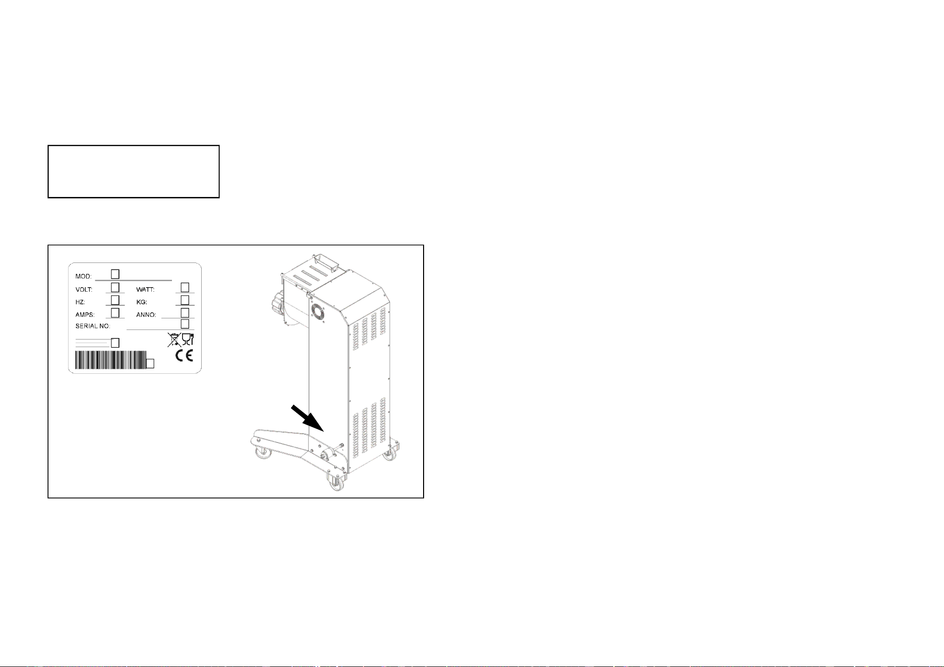
1.7 - Identification of the equipment
Providing an exact description of the "Version", the "Serial Number" and the '' Year
of manufacture" of the machine will allow rapid and effective answer from our
customer service. It is recommended to indicate the machine version and serial
number whenever you call for service.
Collect these data from the plate shown in Fig. 1.7.1. It is suggested to insert the
machine identification data in the following table:
WARNING!
Do not alter the data on the identification plate under any any circumstances.
Fig. 1.7.1
A = machine version
B = Voltage
C = motor power
D = motor frequency Hz
E = Weight
F = Amperage
G = Year of manufacture
H = Serial No.
I = Manufacturer
L = Barcode
A
B C
D E
F G
H
I
L
Machine version…………………………..
Serial No.…………………………………..
Year of manufacture……………………...
Type………………………………………...
15
6 - Using the machine
6.1 Instructions
WARNING!
Only authorized personnel can operate on the machine.
Priori to the start up the operator must first ensure all the guards are in place and
all the safety devices are present and effective. Otherwise, shut the machine down
and contact the operator in charge with maintenance.
Ensure that the of flour / egg ratio is always
1kg of flour / 400g of egg.
Prior to start up, arrange the machine with the suitable extruder, spiral and mixing
paddle
6.2 - Dough preparation
1. Pour the flour mix in the mixing basin
2. Close the top cover and insert the funnel "4" (Figure 2.1.1) on the feeder cap
3. Start the machine in mixer mode by means of the button "2" (Figure 3.1.1)
4. Start pouring the eggs already beaten in the feeder funnel
5. After the eggs where poured, wait for the dough to be ready (about 15 min)
6. Shut down the machine
6.3 - Extrusion
1. Start the machine in extruder mode through button 1 (Fig. 3.1.1) and draw
roughly 50 g of product to clean the extrusion channel
2. Switch the machine off and replace the dough die with the desired die inside the
ring
3. Start the machine in extruder mode through button 1 (Fig. 3.1.1)
4. The screw feeder will put pressure on the pasta. As soon as the pasta reaches
the right pressure, it will start being drawn.
5. Take the pasta leaving the die and cut it with a knife to the desired length.
6. Switch the machine off after emptying the tank.
7 - Maintenance
7.1 - Prescriptions
WARNING! All maintenance and cleaning intervention must only be carried out
with the machine shut down and disconnected from the mains.
The area where maintenance is performed must always be clean and dry.
Do not allow unauthorized personnel to operate on the machine.
Any possible replacement of components, including the replacement tools, must
be carried out with original spare parts by authorized workshops or directly by the
manufacturer.
14
4.4 - Electrical connections
WARNING!
Ensure the mains match the voltage given on the equipment’s ID plate. All inter-
ventions must be carried out exclusively by specialized and expressly authorized
personnel. Carrie out the electrical connection to properly earthed mains.
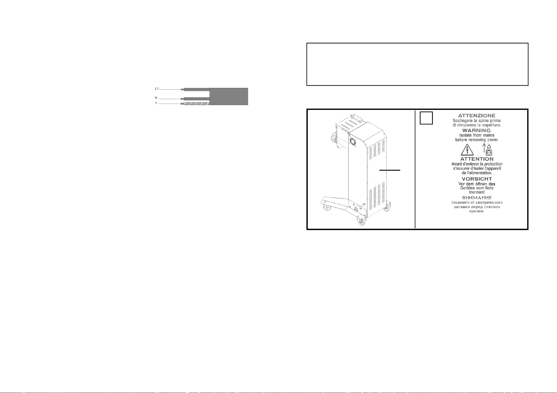
4.4.1 - Single phase machine 230 Volt - 60 Hz
In this version the machine is supplied with a
power cable having 3 x 1.5 mm cross sec-
tion. The cable is connected to a three-poles
single-phased plug.
Connect the cable to single phase 230 Volt-60 Hz mains; interpose a differential
circuit breaker of 16 amps.
5 - Starting-up and shutting-down
5.1 - Checking the electrical connections
Connect the plug to the mains and press the start button (2 Fig. 3.1.1). The ma-
chine gets enable din extruding mode; ensure the spiral direction of rotation is
counter-clockwise.
Otherwise, disconnect the machine from the mains and contact your supplier.
Note: In the machines connected to a single phase line, manufactured for this
specific power supply, the correct direction of rotation is determined directly by the
manufacturer.
5.2 - Checking presence and effectiveness of safety devices and
protections
1 - Interlocked cover
Ensure the machine stops when the upper cover is open.
When the cover is open the machine must not run.
5.3 - Checking the effectiveness of the stop button (fig. 3.1.1)
When machine is connected to the mains and tools are in movement, press the
shut down button (4 Fig. 3.1.1). The machine must shut down.
5.4 - Machine start up (fig. 3.1.1)
After having properly connected the machine to the mains, push the mixing button (2 Fig.
3.1.1) or push the extruding button (1 or 3 Fig. 3.1.1), to have the machine started up.
5.5 - Machine shut down (fig. 3.1.1)
To shut down the machine, push the shut down button, “4” Fig. 3.1.1.
7
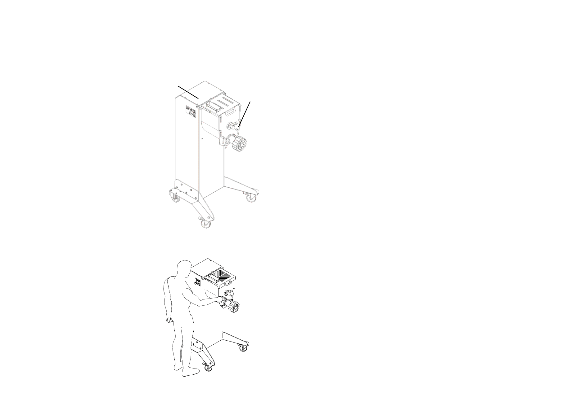
1.7.1 - Warning plates (fig. 1.7.2)
WARNING!
Do not intervene on electrical components when the machine is connected to the
mains. Ones risks electrocution. Follow the indications on the plates.
Failure to comply to the recommendations could result in personal injury.
Make sure the plates are always in place and readable.
Otherwise apply or replace them.
A
Fig. 1.7.2
A
8
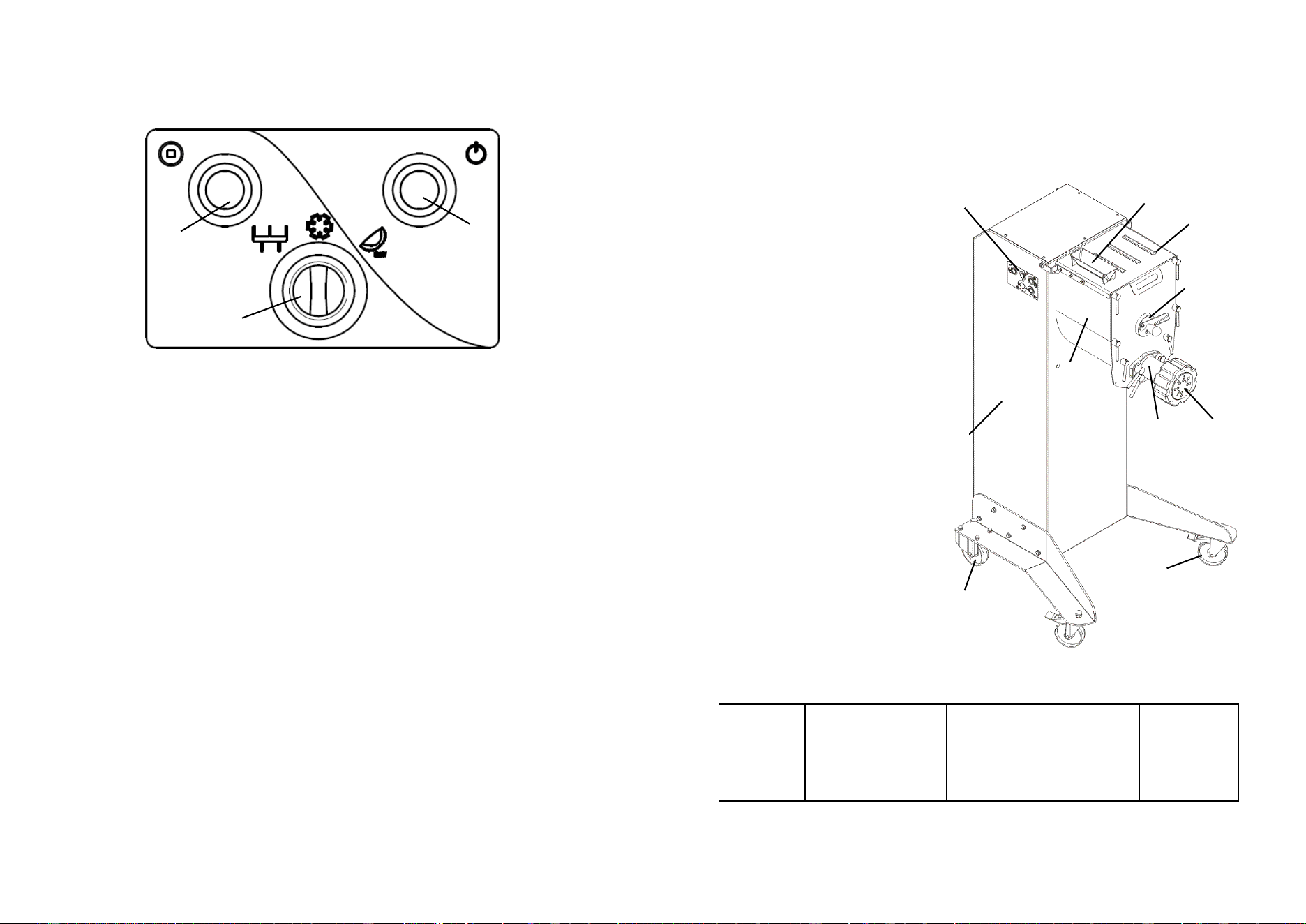
1.8 - Safety devices and protections
WARNING!
Before use ensure that all the safety devices are installed and working properly.
Before each working shift ensure that all the safety devices are installed and that
they are working properly. Otherwise contact the person in charge with
maintenance activity.
1 - Cover sensor.
It prevents the starting up of the machine
in case the cover is up.
2 - Front presence sensor of the tank. It does not
allow the machine to be switched on if the front
panel is missing.
WARNING!
Do not tamper with the safety devices.
1.9 - Operating station
The correct position that the operator must
occupy to optimize the working with the
machine is shown in fig. 1.9.1.
Fig. 1.9.1
1
Fig. 1.8.1
2
13
4 - Inspection, shipping, delivery and installation
4.1 Inspection
The equipment in your possession has been tested at our factory to verify that all
moving parts work properly and it is properly adjusted. The tests are carried out
with materials similar to those processed by the user.
4.2 - Shipping and handling the machine
All materials shipped have been thoroughly checked before delivery to the
shipping company. Unless otherwise agreed upon with the customer, the machine
is wrapped with nylon and fixed with steel straps on the bench, cover by a box
which is also fixed with steel straps to the pallet. On receiving the machine, check
the integrity of the packaging. In case of damage to the packaging, the carrier shall
sign the notice of receipt for instance which should sound like this: "I tentatively
accept..." and the reason.
ON opening the packaging, in case of badly damaged components of the machine,
file a complaint to the shipping company within three days from the date indicated
on the documents.
4.3 - Installation
WARNING!
The machine installation area has to be sturdy and the surface has to ensure a
safe support. When positioning the machine keep extensive space around it. This
allows greater manoeuvrability during operation and ensures access for
maintenance. Prepare suitable lighting around the machine to ensure proper
visibility to the machine operator.
- Remove the cellophane wrapping off the machine and other packaging present
on the inside.
4.3.1 - Disposing the packaging
The components such as cardboard, nylon, wood products are comparable to
municipal solid wastes. They can therefore be freely disposed off. The Nylon is a
pollutant material that produces toxic fumes when burned. Do not burn it; dispose
it off in accordance with the laws in force regarding the matter. If the machine is
delivered in countries where special rules are implemented, the packaging must be
disposed off according to such regulations.
4.3.2 - Handling the machine
WARNING!
Handle the machine with care and attention, avoid accidental falls that could
damage it. To avoid muscle strain, when lifting the machine, use the force of the
legs.
12
3 - List of controls and indicator lights
3.1 - List of controls and indicator lights
1 - Start button
By pushing the button the machine starts.
2 - Shut down button
Push this button to shut down the machine.
3 - Operating mode selector
A - kneading mode: the auger rotates clockwise bringing the product
towards the bottom of the bowl.
B - extruder mode: the auger rotates anticlockwise bringing the product
towards the extruder. The auger puts the dough under pressure towards
the extruder and the pasta begins to extrude. With this function the motor is
powered at 50 Hz by making the auger rotate at 28 rpm.
C - slow extruder mode: the auger rotates anticlockwise bringing the
product towards the extruder. The auger puts the dough under pressure
towards the extruder and the pasta begins to extrude. With this function the
motor is powered at 30 Hz by making the auger rotate at 18 rpm. This
function is dedicated to use of the ravioli maker.
Fig. 3.1.1
2
3
1
A
B
C
9
2 -Technical features
2.1 - Main components
To facilitate the understanding of the manual, hereafter there are listed below and
shown in fig. 2.1.1. the main parts of the machine
1 - Fixed wheels
2 - Castor wheels
3 - Dough basin
4 - Feeder funnel
5 - Commands
6 - Blade unlocking lever
7 - Casing
8 - Interlocked cover
9 - Extruder
10 - Dough outlet and helix
2.2 - Technical features
Motor Supply Dough
capacity
Output/h. Dies
watt / Hp V / Hz Kg kg/h. ø mm
2250 / 3 230 / 60 9.8 20 100
Fig. 2.1.1
1
2
3
4
7
8
6
9
5
10
10
2.3 - Dimensions and weight of the machine
2.4 - Noise level
The measured machine equivalent noise level does not exceed 70 dB.
A B C D E F G
Net
weight
mm mm mm mm mm mm mm kg
680 600 780 810 1690 1390 900 118
A
B
C D
E
F
G
Fig. 2.3.1
11
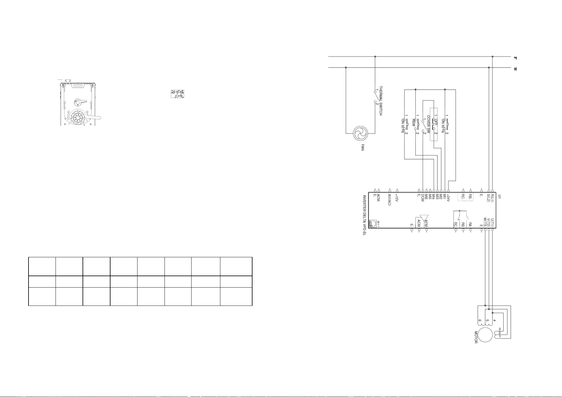
2.5 - Electrical diagrams
2.5.1 - 230V / 60 Hz 1 ph