2
INSTALLER: Leave these instructions with the consumer.
CONSUMER: Retain these instructions for future reference.
TESTED IN ACCORDANE WITH: ANSI Z21.58-2022 AND CSA 1.6-2022
THE STANDARD FOR OUTDOOR COOKING GAS APPLICANCES.
CODE REQUIREMENTS:
Installation of this cooking appliance must conform to local codes. In the absence of local codes, this unit
should be installed in accordance with the National Fuel Gas code ANSI Z223.1/NFPA 54, the Natural Gas
and Propane Installation code CSA B149-1, or the Propane Storage and Handling Code CSA B149.2.
All Electrical Components must be electrically grounded in accordance with local codes or in the absence
of local codes with the National Electrical Code NFPA 70 or Canadian Electrical code Part 1 (CSA C22.1).
FOR OUTDOOR INSTALLATION AND USE ONLY:
This outdoor cooking gas appliance must only be used outdoors and must not be used in a building,
garage, or any other enclosed area.
! WARNING
1. DO NOT STORE OR USE GASOLINE OR OTHER
FLAMMABLE LIQUIDS OR VAPORS IN THE VICINITY
OF THIS OR ANY OTHER APPLIANCE.
2. AN LP CYLINDER NOT CONNECTED FOR USE
SHALL NOT BE STORED IN THE VICINITY OF THIS
OR ANY OTHER APPLIANCE.
! DANGER
IF YOU SMELL GAS:
1. SHUT OFF GAS TO THE APPLIANCE
2. EXTINGUISH ANY OPEN FLAME.
3. OPEN LID.
4. IF ODOR CONTINUES, KEEP AWAY FROM THE AP-
PLIANCE AND IMMEDIATELY CALL YOUR GAS SUP-
PLIER AND OR FIRE DEPARTMENT.
1. NE PAS ENTREPOSER NI UTILISER DE L’ESSENCE NI
D’AUTRES VAPEURS OU LIQUIDES INFLAMMABLES À
PROXIMITÉ DE CET APPAREIL NI DE TOUT AUTRE
APPAREIL.
2. UNE BOUTEILLE DE GPL QUI N’EST PAS RACCOR-
DÉE EN VUE DE SON UTILISATION NE DOIT PAS
ÊTRE ENTREPOSÉE À PROXIMITÉ E CET APPAREIL
NI DE TOUT AUTRE APPAREIL.
! AVERTISSEMENT
! DANGER
S’IL Y A UNE ODEUR DE GAZ:
1. COUPEZ L’ADMISSION DE GAZ DE ‘LAPPARIEL.
2. ÉITENDRE TOUTE FLAME NUE.
3. OUVRIR LE COURVERCLE.
4. SI L’ODEUR PERSISTE, ÉLOIGNEZ-VOUS DE L’APPA-
REIL ET APPELEZ IMMÉDIATEMENT LE FOURNIS-
SEUR DE GAZ OU LE SERVICE D’INCENDIE.
CALIFORNIA PROPOSITION 65 - WARNING Pursuant to California Health & Safety Code Sec. 25249.6
Appliances that use Natural Gas and Propane emit toxic combustion byproducts, that are on the list of
substances which are known by the State of California to cause cancer and / or birth defects or other
reproductive harm. To minimize exposure to these substances, always operate this unit in a well ventilat-
ed area and according to this use and care manual.
For additional information, please go to https://www.p65warnings.ca.gov .
3020914
1085 Bixby Drive
City of Industry, CA. 91745
(888) 383-8800
www.alfrescogrills.com
Artisan
3
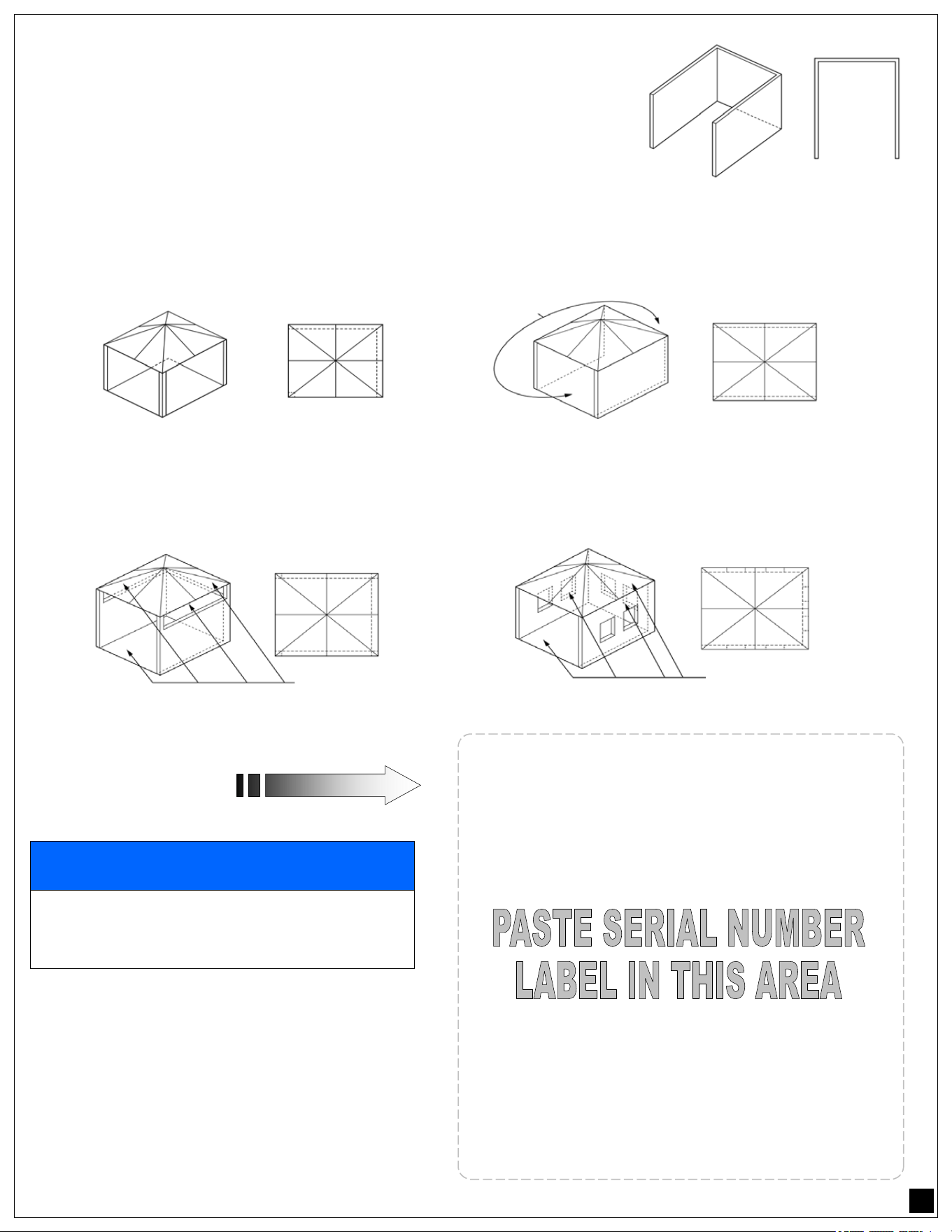
ILLUSTRATIONS AND DEFINITIONS OF OUTDOOR AREAS:
An appliance is considered to be outdoors if installed with shelter
no more inclusive than with walls on three sides, but with no over-
head cover (see image # 1) ; all openings must be permanently
open; sliding doors, garage doors, windows, or screened openings
are not considered as permanent openings or,
An appliance is considered to be outdoors if installed with shelter no more inclusive than within a partial
enclosure that includes an overhead cover and no more than two sidewalls. The sidewalls may be parallel,
as in a breezeway, or at right angles to each other (see image # 2 and # 3). All openings must be perma-
nently open; sliding doors, garage doors, windows, or screened openings are not considered as permanent
openings.
An appliance is considered to be outdoors if installed with shelter no more inclusive than within a partial
enclosure that includes an overhead cover and three sidewalls, as long as 30% or more of the horizontal
periphery of the enclosure is permanently open. (see image # 4 and # 5), All openings must be perma-
nently open; sliding doors, garage doors, windows, or screened openings are not considered as perma-
nent openings.
APPLIANCE SERIAL
NUMBER LABEL:
CLEARANCES:
It is necessary to maintaining proper clearances
from combustible construction, the specific mini-
mum clearances from such construction to the
sides and back of this cooking gas appliance is
shown in the serial label.
Image # 1
! NOTICE
THIS OUTDOOR COOKING APPLIANCE IS NOT
INTENDED TO BE INSTALLED IN OR ON BOATS.
THIS APPLIANCE IS NOT INTENDED TO BE IN-
STALLED IN OR ON RECREATIONAL VEHICLES.
Image # 2
Image # 3
BOTH ENDS
OPEN
Image # 4
30% OR MORE OF THE HORIZONTAL
PERIPHERY OF THEENCLOSURE IS
OPEN AND UNRESTRICTED
Image # 5
30% OR MORE OF THE HORIZONTAL
PERIPHERY OF THEENCLOSURE IS
OPEN AND UNRESTRICTED

4
LOCATING AND ASSEMBLING THE GRILL:
When determining a suitable location for your grill, take into account the outdoor area as determined on
page 3 and concerns such as wind exposure, rain, sprinklers, proximity to traffic paths and keeping any
gas supply line runs as short as possible.
Locate the grill only in a well-ventilated area. Never locate the grill in a building, garage, or other such
enclosed areas without an approved ventilation system. Never locate the grill over, under or next to
unprotected combustible construction. During heavy use, the grill will produce a lot of smoke.
CLEARANCES:
TO NON-COMBUSTIBLE CONSTRUCTIONS:
A minimum of 3-5/8” clearance from the back of the grill to non-combustible construction is required to
allow the hood to be fully opened.
TO COMBUSTIBLE CONSTRUCTIONS:
The minimum clearance of the unit to combustible construction is indicated in the serial plate on page 3.
ASSEMBLY:
BUILT-IN MODELS: Before locating your Artisan Grill into your non-combustible enclosure, please
complete the following steps:
1. Remove all packaging materials.
2. Ensure that the burners are positioned correctly on their orifices, and are fully seated onto their
supports. (See page 5)
3. Position the briquette trays onto their support ledge.
4. Make the connection to the gas regulator according to the instructions on pages 11 thru 19 for
your gas type.
5. To comply with safety and service requirements, the main gas shut off valve must be
accessible from front of grill without using any tools.
Your Artisan Grill has provision for mounting onto a mobile cart if you choose to do so.
Contact your
Artisan dealer for the appropriate cart for your grill.
FREE STANDING (CART) MODELS: Please complete the following steps:
1. Remove all packaging materials.
2. Ensure that the burners are positioned correctly on their orifices, and are fully seated onto their
supports. (see page 5)
3. Position the briquette trays onto their support ledge.
4. Make the connection to the gas regulator according to the instructions on pages 11 thru 19 for
your gas type.
5. Allow a minimum of 3” clearance around all sides of grill cart for proper air movement.
6. Lock the front casters to prevent unwanted grill / cart movement.
NOTE:
To prevent lighting problems and ensure proper operation of your grill, it is imperative that the burners are
properly installed and aligned with respect to the gas orifices.
5
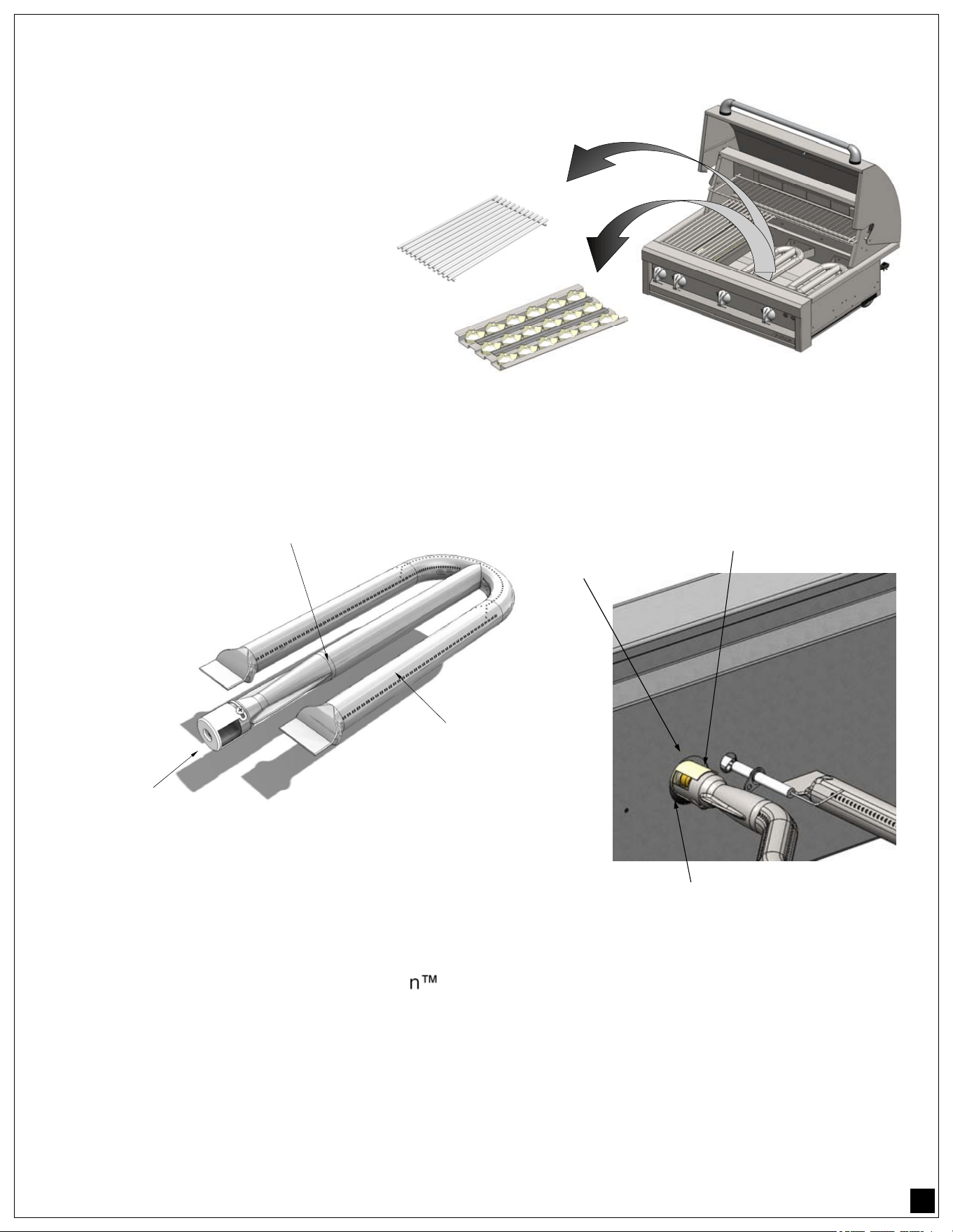
BURNER PLACEMENT:
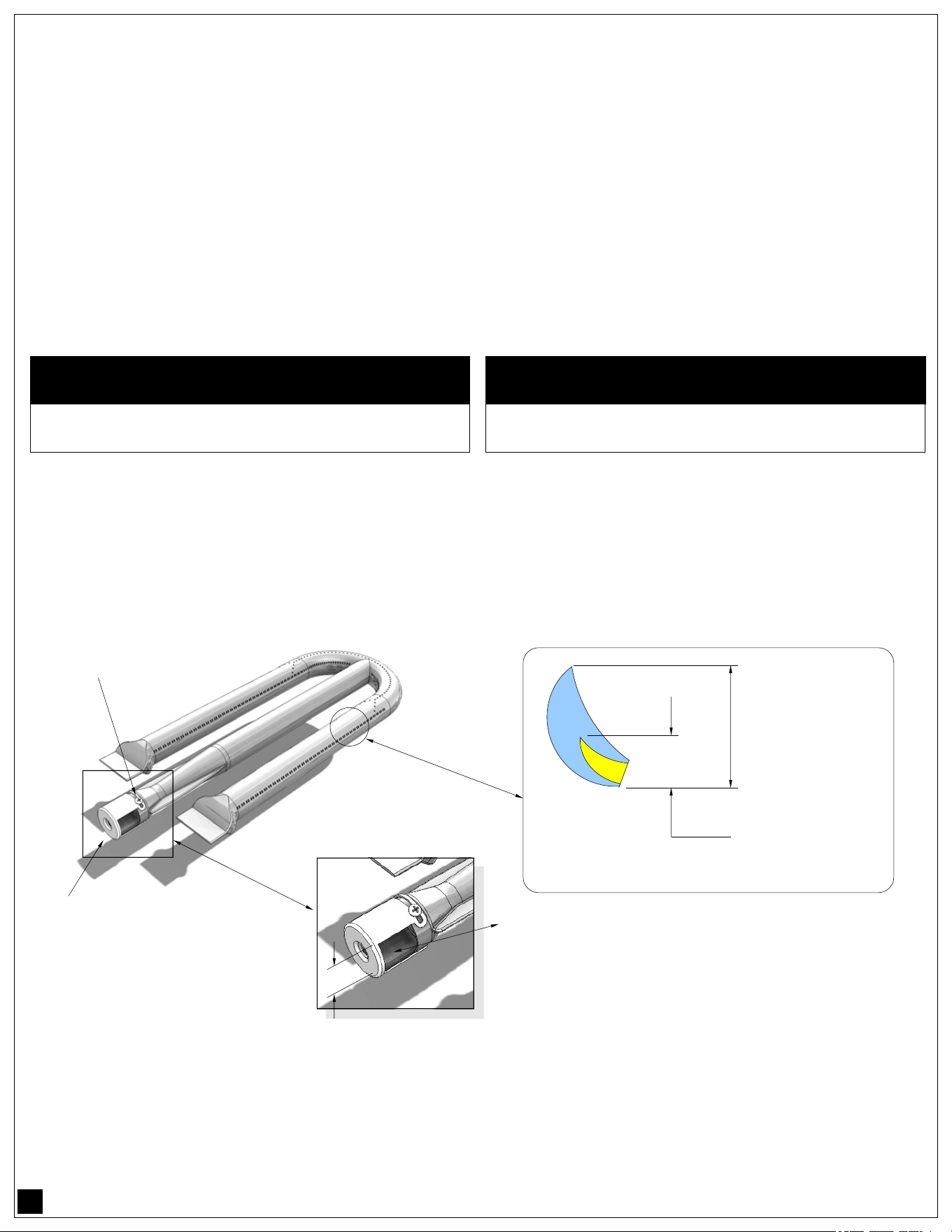
The main burners (U-Burners) are located below the grates and
briquette trays. To access the burners lift the grates and the briquette
trays out of the cooking surface of the grill.
Located directly below the
briquette trays, the burners
are resting between the rear
support backet and the gas
orifice at the front of the grill
(directly behind the firewall).
The air shutter adjustment screws are accessible with a flat
screwdriver by removing the burner. Loosen the screw of the air shutter. Reinstall the burner. Make certain
that the burners are sitting properly on the orifices taking care not to move or damage the igniter electrode.
LEAK TESTING:
GENERAL INFORMATION:
Although all gas connections on your Artisan
Grill are leak tested at the factory prior to shipment, a
complete gas tightness check must be performed at the installation site due to possible mishandling in
shipment, or excessive pressure unknowingly being applied to the unit.
Periodically check the whole system for leaks, or immediately check if the smell of gas is detected.
In order to check for leaks, it is necessary to connect and pressurize the grill with the fuel supply system of
your choice such as a local liquid propane (LP) tank system or a fixed piped system of natural gas (NG) or
a remote LP system.
Follow the fuel connection instructions in this manual prior to conducting any leak testing.
REMOVE GRATES
BRIQUETTE TRAYS ARE
LOCATED OVER THE BURNERS
SHUTTER
AND INLET
PORT
SUPPLY
VENTURY
TUBE
MAIN BURNER
MAIN U-BURNER
BURNER SHUTTER
NOTCH
INLET
MAIN
BURNER
6
GAS CONNECTIONS INFORMATION:
For LP or NG fuel systems with flexible hoses, please inspect the hose before each use of the outdoor
cooking gas appliance. If it is evident that there is excessive abrasion or wear, or the hose is cut, it shall be
replaced prior to the outdoor cooking gas appliance being put
into operation.
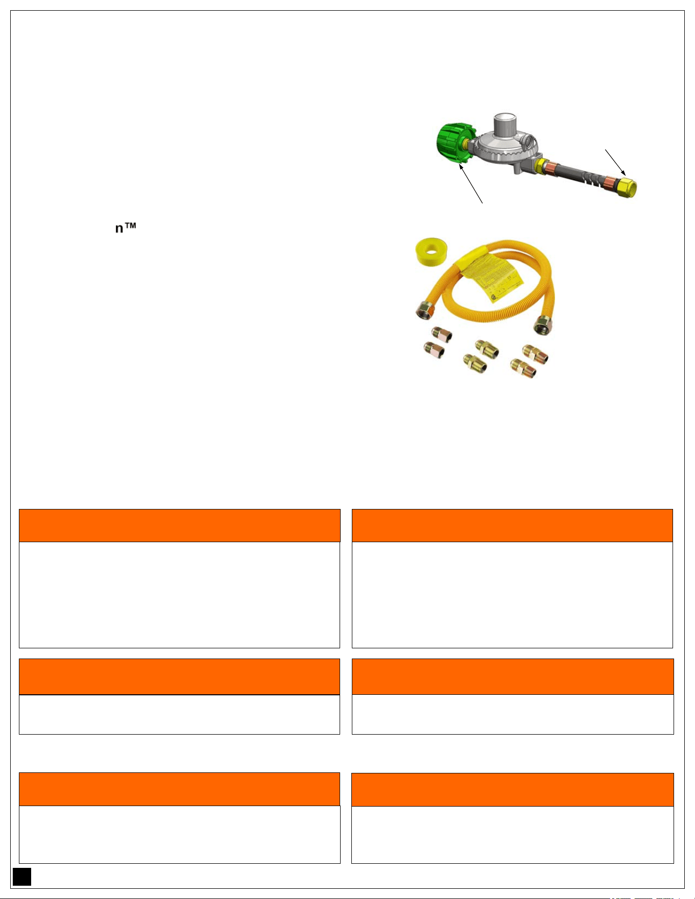
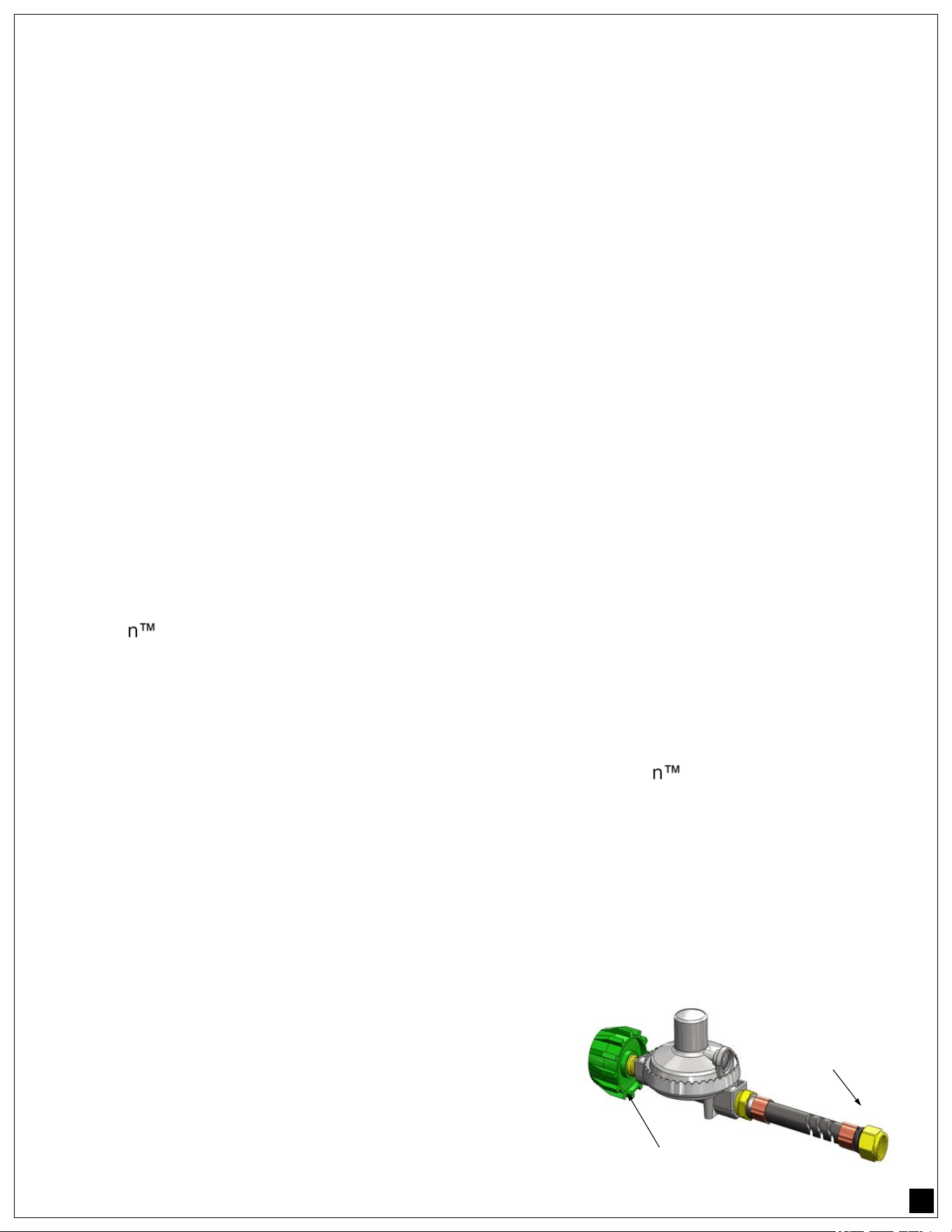
If the unit is installed with a flexible rubber hose / regulator
assembly, only replace with assembly part number:
• PROP-KIT-01
This assembly consists of a 36” long hose with a 3/8” ODF
fitting and dual in-line regulator with a QCC1 connection.
Contact Artisan Grills for replacement.
If the unit is installed with a flexible metal (stainless) hose or a
coated stainless hose, (minimum 1/2” ID for NG and 3/8” ID
for LP), similar hoses are available for replacement at
plumbing stores, supply warehouses or home centers.
All rigid pipes, semi-flexible tubing and connectors must
comply with ANSI Z21.75 and CSA 6.27 as suitable for
outdoor installation.
The maximum length of the connection must be 6 Ft (1.82 m).
CONNECTION ACCESS:
FOR BUILT IN UNITS: Locate the access plate or door provided in the outdoor counter or island for
inspection of gas lines / shut-off valves and electrical connections.
FOR CART MOUNTED UNITS: For LP cart mounted units, inspection of the flexible hose, regulator and
tank can be done by opening the doors of the cart. For NG cart mounted units, the flexible hose is available
for inspection on the back of the cart unit.
LE CAPOT DOIT ÊTRE OUVERT LORSQUE L'ALLUM-
AGE DE LA HOTTE DU GRIL. NE DOIT PAS ÊTRE FER-
MÉ PENDANT DE LONGUES PÉRIODES LORSQUE DES
BRÛLEURS IR SONT UTILISÉS.
! AVERTISSEMENT
HOOD MUST BE OPEN WHEN LIGHTING THE GRILL.
HOOD SHOULD NOT BE CLOSED FOR LONG PERIODS
WHEN IR BURNERS ARE IN USE.
! WARNING
GARDER TOUT LE CORDON ÉLECTRIQUE ET LE TUYAU
D'ALIMENTATION DE CARBURANT À L'ÉGARD DE TOUTES
SURFACES CHAUFFANTES.
! AVERTISSEMENT
KEEP ANY ELECTRICAL CORD AND FUEL SUPPLY
HOSE AWAY FROM ANY HEATED SURFACES.
! WARNING
TYPICAL GAS
CONNECTION KIT
AVAILABLE AT
HOME CENTERS
COMPRISES OF
HOSE, ADAPTERS
AND / OR REDUC-
ERS AND GAS
APPROVED SEAL-
ING TAPE.
ELECTRICAL GROUNDING INSTRUCTIONS:
THIS OUTDOOR COOKING GAS APPLIANCE IS
EQUIPPED WITH A THREE-PRONG (GROUNDING) PLUG
FOR YOUR PROTECTION AGAINST SHOCK HAZARD
AND SHOULD BE PLUGGED DIRECTLY INTO A
PROPERLY GROUNDED THREE-PRONG RECEPTACLE.
DO NOT CUT OR REMOVE THE GROUNDING PRONG
FROTH THIS PLUG.
! WARNING
INSTRUCTIONS DE MISE À LA TERRE ÉLECTRIQUE
CET APPAREIL DE CUISSON AU GAZ D’EXTÉRIEUR
EST ÉQUIPÉ D’UNE FICHE À TROIS BROCHES (MISE À
LA TERRE) POUR VOTRE PROTECTION CONTRE LES
RISQUES D’ÉLECTROCUTION ET DEVRAIT ÊTRE
BRANCHÉ DIRECTEMENT DANS UNE PRISE À TROIS
BROCHES CORRECTEMENT MISE À LA TERRE. NE PAS
COUPER OU ENLEVER LA PRISE MISE À LA TERRE.
! AVERTISSEMENT
3/8” ODF
CONNECTOR
QCC1 CONNECTOR
7
LIGHTING INSTRUCTIONS:
BUTTON SYMBOLS AND LOCATIONS:
ILUMINATION LIGHTS IN YOUR GRILL:
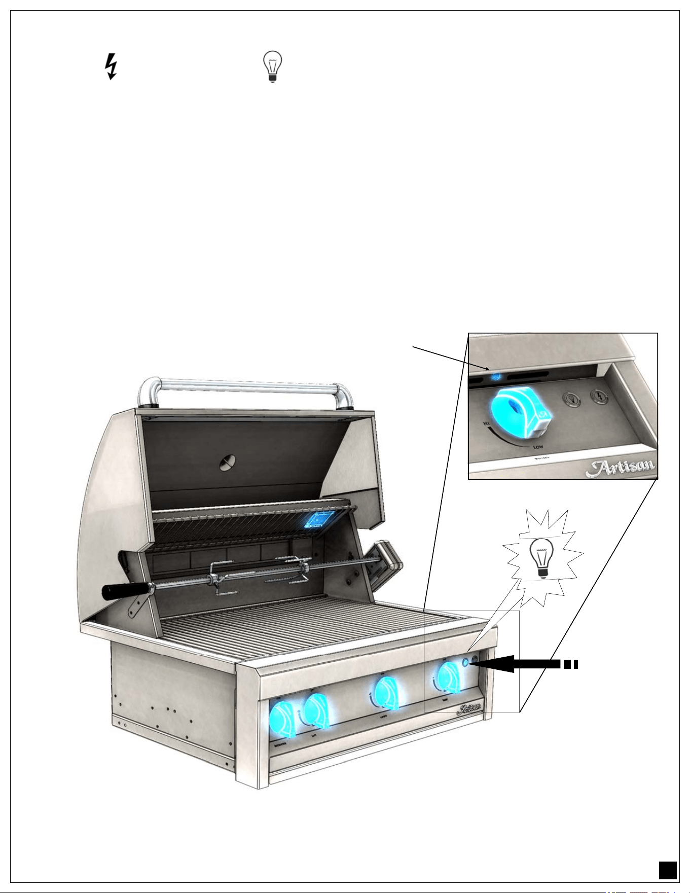
There are two types of lights on your ARTP/ART Grill, incandescent in the cooking area and LED blue panel
lights under the control panel (
See illustration below).
Both lights systems are controlled with one light switch button.
Open the hood, press the proper light switch button (see symbols above and illustration below).
NOTE:
Incandescent light bulb is located on the right side of the rear hood above the cooking area. The
area around the light fixtures and the light fixtures themselves become extremely hot during grill operation with
or without the lights being turned on.
TOP SWITCH:
IGNITER BUTTON
MIDDLE SWITCH:
LIGHT FIXTURES
PUSH TO
POWER
LIGHTS
LED LIGHT
8
GRILL BURNERS LIGHTING:
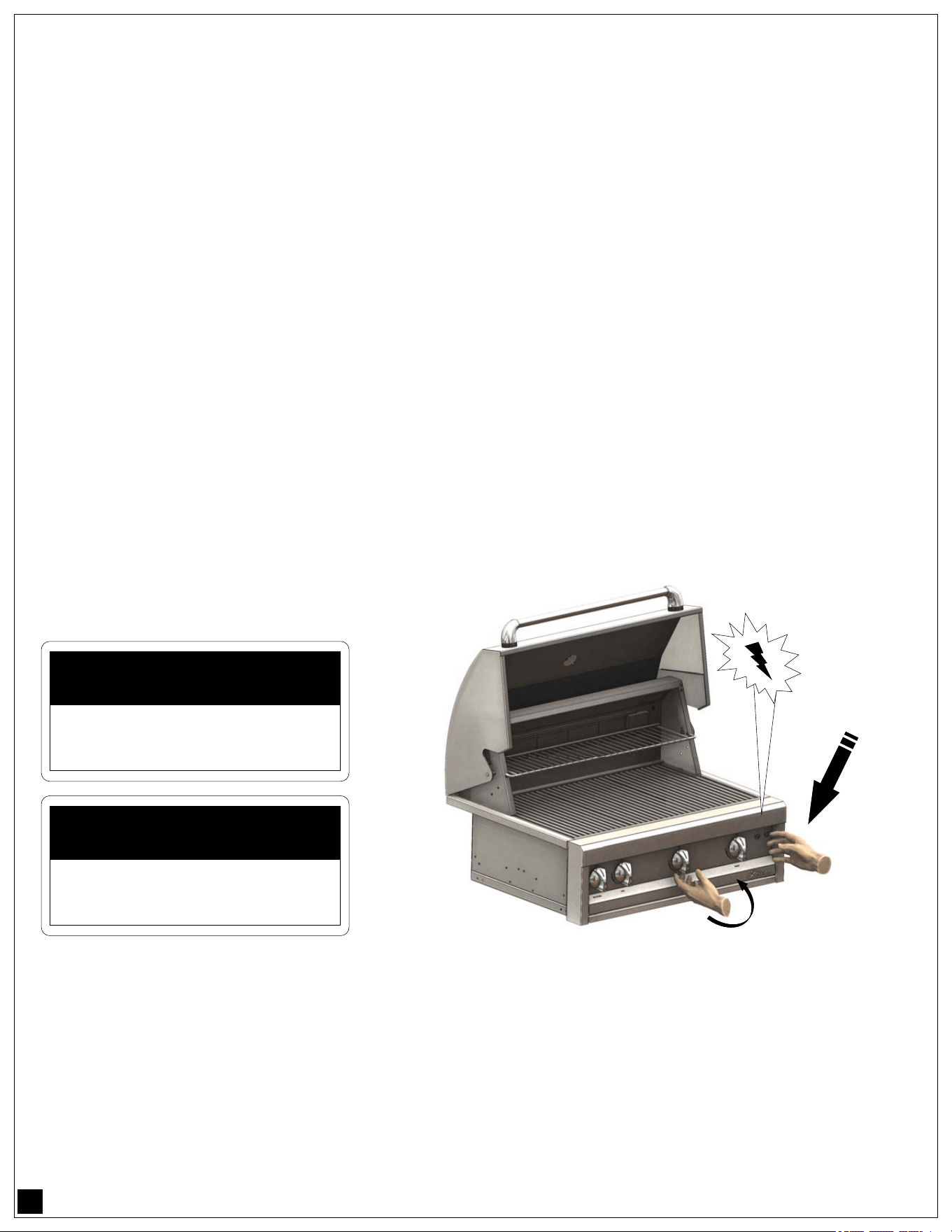
Always keep your face and body as far away from the grill as possible when lighting !.
Lift the hood, depress the igniter button for the burner you are trying to light, and immediately push and turn
the burner control knob counter-clockwise to the “HI” position and wait for the burner to light. (See
illustration below).
NOTE: The first burner may take longer to light while air is purged from the gas supply system.
If the burner does not light within 4 seconds, turn knobs to “OFF” and wait 5 minutes to allow any
accumulated gas to dissipate before trying again. If the burner will not light after several attempts, then it
can be lit with a match.
Keep your face away from the grill as far as possible and pass a lit, long stem match through the notch in
the grill rack to the ports of the burner you are trying to light. When attempting to light a burner with a
match, ensure that the correct burner control knob is used.
Position the match near the burner ports. Push and turn the control knob to “HI”. Repeat procedure on each
burner if necessary. If the burner does not light in 4 seconds turn the knob OFF, wait 5 minutes and try
again. If the burner will not light after several attempts see page 34: Troubleshooting.
To assure that an IR burner is lit, very carefully
place your hand 8-10 inches away from the
burner surface. If you do not feel the heat of the
burner, shut off control knob, wait five minutes,
and attempt to relight.
SIDE BURNER LIGHTING:
Push and turn the side burner right hand control knob to the “HI” position and immediately depress the
igniter button. You’ll hear a snapping sound from the spark which is being generated at the side burners. It
is necessary to keep the igniter button depressed until the burner is lit.
If the burner does not light in 4 seconds, turn knobs to “OFF” and wait 5 minutes to allow any accumulated
gas to dissipate before trying again. If the burner will not light after several attempts, then it can be lit with a
match.
NOTE: To ensure proper spark ignition, do not change the gap between the electrode wires and the
burners. The optimum gap is preset at the factory between 1/8” and 3/16”.
! CAUTION
IN SUNNY ENVIRONMENTS, THE
FLAME FROM AN IR BURNER
MAY BE IMPOSSIBLE TO SEE.
! MISE EN GARDE
DANS LES ENVIRONNEMENTS
SOLEILS, LA FLAMME D'UN
PUSH TO
IGNITE
PUSH & TURN TO “HI”

9
ROTISSERIE BURNER LIGHTING:
Open the lid, press the igniter button (see page 8) and then turn the control knob to the “HI” position. If the
burner does not light within 4 seconds, turn the control knob to “Off”, wait five minutes and attempt to
relight. If the igniter does not function, you can light the burner by holding a lit match to the burner (with the
control knob at the “HI” position).
After your first use of the rotisserie burner it is likely that the stainless steel adjacent and directly above the
burner will darken to a dark blue color. This is a normal property of the corrosion resistant, type 304
stainless steel used in the manufacturing of your barbecue, and is not detrimental to its operation.
PREHEATING THE GRILL (U-BURNERS):
Preheating the grill is important for best performance. To preheat the grill when cooking with the U-burners,
close the hood after lighting the burners as described above. Set the grill control knobs on “HI” for 15
minutes.
PREHEATING THE GRILL (IR-BURNERS):
Preheating the IR burners is important to protect them from food drippings. After lighting the IR burners as
described above, allow to preheat on “HI” for four minutes before beginning to grill.
If your grill is equipped with a SEAR-ZONE IR BURNER, light and preheat the U-BURNERS first, then
light and preheat the SEAR-ZONE IR BURNER.
PREHEATING THE ROTISSERIE BURNER:
Light the rotisserie burner as described in the lighting instructions. Once lit, the rotisserie burner will reach
cooking temperatures in about 1 minute.
BURNER ADJUSTMENTS:
NOTE: Artisan grills are available with both U-burners and IR burners. The following instructions apply
only to the U-burners. IR burners do not require adjustment and need only be checked visually for proper
performance. On high, an IR burner should glow red evenly over its entire surface.
U-BURNER AIR ADJUSTMENT:
Each grill burner is tested and adjusted at the factory prior to shipment; however, variations in the local gas
supply, elevation and other factors might make it necessary to adjust the burners. The flames of the
burners should be visually checked and compared with illustration on page 25.
Flames should be blue and stable with no yellow tips, excessive noise or lifting.
If any of these conditions exist, check if dirt, debris, spider webs, etc., are blocking the air shutter or burner
ports. Proceed with air shutter adjustment.
AIR SHUTTER ADJUSTMENT:
A sheet metal cap at the inlet of the burner called the “AIR SHUTTER” regulates the amount of air that
enters into the burner for combustion. The air shutter is locked in place by a screw, which must be loosened
prior to lighting the burner for adjustment.
10
The air shutter adjustment screws are accessible with a flat screwdriver by removing the burner. Loosen
the screw of the air shutter. Reinstall the burner. Make certain that the burners are sitting properly on the
orifices taking care not to move or damage the igniter electrode.
Light the burners and adjust according to the following directions:
• Turn the valve on “HI”, light the burner and allow it to “WARM UP” for 10 minutes.
• If the flame is yellow, indicating insufficient air, turn the air shutter counter-clockwise to
allow more air into the burner.
• If the flame is noisy and tends to lift away from the burner, (WITH THE BRIQUETTE
TRAYS IN POSITION) indicating too much air, turn the air shutter clockwise to reduce the
amount of air to the burner.
• Retighten the locking screw of the air shutter cap.
NOTE: Be careful, as the burner could be and / or will become very hot after lighting it.
Flames should be blue and stable with no yellow tips, excessive noise or lifting.
GENERAL MAINTENANCE INSTRUCTIONS:
1. Keep the outdoor cooking gas appliance area clear and free from combustible materials, gasoline,
and other flammable vapors and liquids;
2. DO NOT obstruct the flow of combustion and ventilation air;
3. Keep the ventilation opening(s) of the cylinder enclosure (if any) free and clear from debris;
4. Visually check burner flames.
For additional information regarding burner flames or adjustments please refer to page 26 and 27 of
this manual.
5. Clean the outdoor cooking gas appliance, including special surfaces, if necessary with
recommended cleaning agents (see detailed cleaning information on pages 30 through 31); and
6. Check and clean burner/venturi tubes for insects and insect nests. A clogged tube can lead to a
fire beneath the grill.
IN SUNNY ENVIRONMENTS, THE FLAME FROM AN
IR BURNER MAY BE IMPOSSIBLE TO SEE.
! CAUTION
DANS LES ENVIRONNEMENTS SOLEILS, LA FLAMME
D'UN BRÛLEUR IR PEUT ÊTRE IMPOSSIBLE À VOIR.
! MISE EN GARDE
AIR SHUTTER
ADJUSTMENT CAP
LOCKING SCREW
U-BURNER
1” MAXIMUM
3
/
8
” MAXIMUM
FLAME SIZE
AIR SHUTTER APPERTURE IS FACTORY
SET TO APPROXIMATELY 1/2” FOR LP &
5/8” FOR NG - MINOR ADJUSTMENTS MAY
BE NECESSARY DUE TO FACTORS SUCH
AS HIGH ALTITUDE LOCATIONS.
11
PARTS AND REPLACEMENTS:
For information regarding obtaining replacement parts please refer to “How to obtain service” on page 39 of
this manual.
OPERATING TEMPERATURE:
The minimum operating temperature for safe use of this outdoor cooking gas appliance is 0 °F (-17.8 °C)
NOTE:
PORTABLE (CART-MOUNTED) OUTDOOR GRILLS MUST NOT BE USED
UNDER OVERHEAD COMBUSTIBLE CONSTRUCTION.
SELF CONTAINED LIQUID PROPANE (LP) GAS SUPPLY SYSTEMS:
L.P. TANK REQUIREMENTS:
Use only a standard 20 Lb. (5 Gallons) propane gas cylinder (18-1/4” H x 12-1/4” Ø). The tank must be
installed in the upright position. Do not use a dented or rusty LP tank as it may be hazardous and should be
checked by your LP supplier. Never use a cylinder with a damaged valve.
The LP cylinder shall be constructed and marked in accordance with the Specification for LP Gas Cylinders
of the U.S. Department of Transportation (DOT) or CSA B339.
The cylinder must be provided with a shut off valve terminating in an LP gas supply cylinder valve outlet
specified, as applicable, for connection type QCC1 according to the standard for compressed gas cylinder
valve outlet and inlet connections CGA 791.
LP GAS CONNECTION TO LP TANKS:
Your Artisan Grill for use with LP gas comes equipped with its own regulator, which MUST NOT be
removed.
There is also a secondary High Capacity, Hose / Regulator assembly for connection to a standard 20 Lb.
LP cylinder. The LP gas pressure regulator and hose supplied with this unit must be used without
alteration.
If this assembly needs to be replaced use only the type specified by Artisan
Grill for this appliance. Only
replace with assembly part number:
• PROP-KIT-01
This assembly consists of a 36” long hose with a 3/8” ODF
fitting and dual in-line regulator with a QCC1 connection.
To connect the LP Regulator / Hose Assembly follow the diagram on the next page:
LP TANK CONNECTION STEPS:
1. Locate the regulator and gas connection point in the
rear right side of your BBQ unit (in cart mounted
models, remove the rear panel from the BBQ cart to
gain access).
2. Attach a 1/2” FPT x 1/2” MPT (male-to-female) elbow to
the regulator.
3. Attach a 1/2” MPT x 3/8” ODF (compression flare fitting)
reducer to the elbow in order to connect to the LP tank regulator / hose assembly.
3/8” ODF
QCC1 CONNECTOR
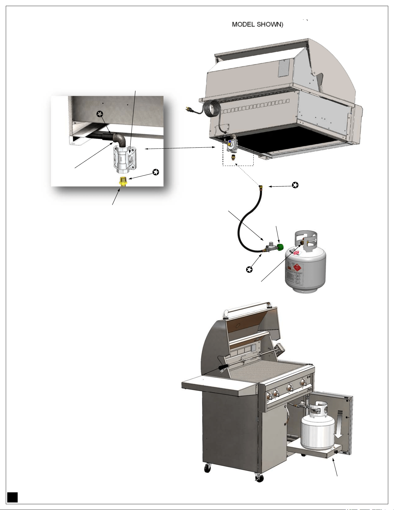
12
TYPICAL ARTISAN BBQ (36”
MODEL SHOWN)
NOTE:
Locations marked with a star ()
are areas of the piping that MUST be
leaked checked after every
connection.
LP CYLINDER CART MOUNTING:
To install the LP cylinder in cart
mounted grills, follow these steps:
• Open the door and pull out the
cart LP cylinder tray to its full
extended position.
• Loosen the LP Cylinder fastener
knob.
• Insert the LP Cylinder vertically
on the tray opening.
• Tighten the fastening knob until
the cylinder is held securely.
TYPICAL 20 LBS.
(5 GALLONS)
LP GAS TANK
LP REGULATOR AND
HOSE ASSEMBLY
CYLINDER FASTENER KNOB
CONVERTIBLE GAS
PRESSURE REGULATOR
1/2” FPT X 1/2” MPT
90° ELBOW
1/2” FPT X 3/8” FLARE
BRASS FITTING
13
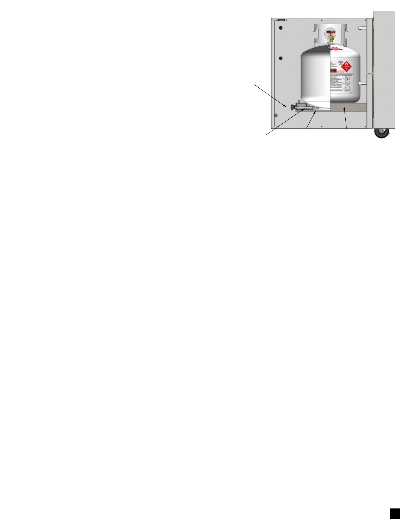
TANK RETENTION POINTS:
The standard 20 Lbs. (5 Gallons) LP tank rests on the center
of the tank tray and it is retained in place (preventing the tank
from tipping sideways) by the locking screw that secures the
bottom ring of the LP tank.
LP REGULATOR HOSE ASSEMBLY RETENTION:
In addition to retaining the LP tank, it is also required to
properly support the LP Regulator / Hose Assembly and
prevent the unit from falling to the ground during LP tank
exchanges as per ANSI Z21.58 regulations.
For this purpose, when installing the included LP Regulator
and Hose Assembly, fasten the assembly to the cart unit-
with the included cart lanyard. (see previous diagram)
NOTE:
LP Tank cylinders of different brands are made of different materials as well as features. Other LP cylinders
may be used with this appliance provided that they are compatible with the retention means as shown on
the illustration above, while utilizing the same cylinder retention means and the same points of contact be-
tween the cylinder and the retention means.
The LP Gas Supply Cylinder to be used must be:
1. Constructed and marked in accordance with the Specifications for LP gas Cylinders of the U.S.
Department of Transportation (DOT) or CSA B339, as applicable;
2. Provided with a listed overfilling prevention device; and
3. Provided with a cylinder connection device compatible with the connection for outdoor cooking
appliance (Type QCC1 connection)
LEAK TESTING LP TANK CONNECTIONS:
BEFORE TESTING:
• Make sure all the grill control knobs are in the OFF position.
• Do not smoke while leak testing.
• Never leak test with an open flame.
• Make a soap solution of one part liquid detergent and one part water for leak testing purposes.
• Always check with a full cylinder.
TO TEST:
• Apply the solution to the gas fittings marked with a star () on the previous page by using a
spray bottle, or a brush to spread the solution.
• Turn the gas supply (LP Tank valve) to the OPEN position..
• Check all connections from the LP cylinder up to and including the manifold pipe assembly.
• Soap bubbles will appear is a leak is present.
• If a leak is present, immediately turn CLOSE the LP Tank valve, tighten any leaking fittings,
turn the gas supply back ON and RECHECK again.
• If you cannot stop a gas leak CLOSE the LP Tank valve and call your dealer where you pur-
chased your grill.
• Do not use the grill until all connections have been checked and do not leak.
ALWAYS CHECK FOR LEAKS AFTER EVERY LP TANK CHANGE.
FASTENER
KNOB
LP TANK
COLLAR
LOCK
SCREW
TANK
TRAY
14
IMPORTANT INFORMATION:
Check all gas supply fittings for leaks before each use. It is handy to keep a spray bottle of soapy water
near the shut-off valve of the gas supply line. Spray all the fittings. Bubbles indicate leaks.
If the outdoor cooking gas appliance is not in use, the gas shall be turned off at the supply cylinder. An out-
door cooking gas appliance may be stored indoors only if the cylinder is disconnected and removed from
the outdoor cooking gas appliance.
Cylinders shall be stored outdoors out of the reach of children and shall not be stored in a building, garage,
or any other enclosed area.
The LP gas cylinder used shall include a collar to protect the cylinder valve.
• Do not store a spare LP gas cylinder under or near this appliance.
• Never fill the cylinder beyond 80% full.
• If the information above is not followed exactly, a fire causing death or serious injury could occur.
This outdoor cooking gas appliance is designed to use a CGA 791 connection. Place a dust cap on the LP
cylinder valve outlet whenever the cylinder is not in use. Only install the type of dust cap on the cylinder
valve outlet that is provided with the cylinder valve. Other types of caps or plugs may result in leakage of
propane.
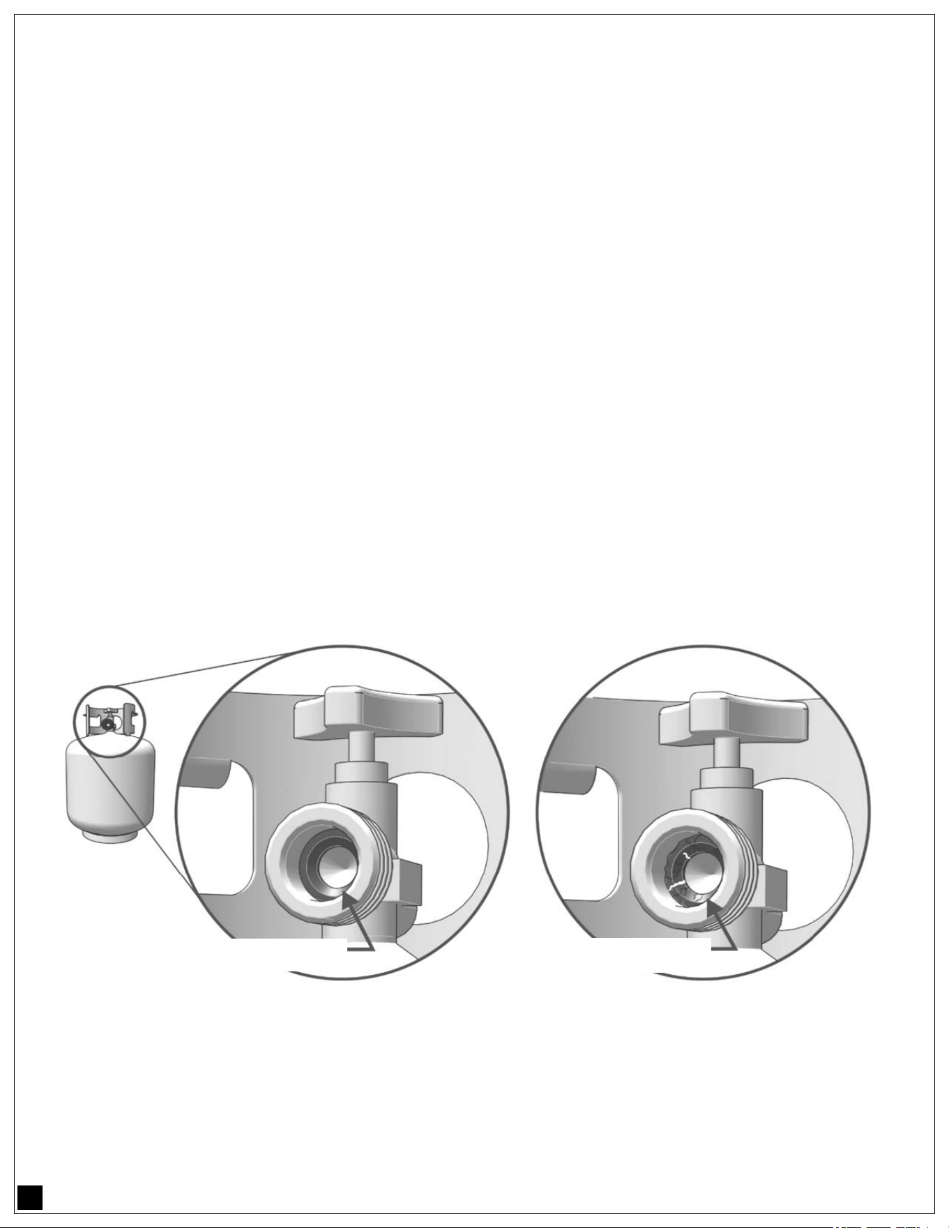
The LP gas cylinder face elastomeric face seal element (O-Ring) on these devices could, over time, show
marked and visible damage or deterioration that might cause a leak even with the connection tightened.
A visual inspection for the seal must be carried out every time a LP gas cylinder is replaced or refilled; any
LP gas cylinder showing signs of damage or deterioration as those illustrated below, including visible
cracks and pitting, must be returned unused to the LP gas cylinder seller.
CART-MOUNTED LP GAS CONNECTION TO AN LP FIXED FUEL SYSTEMS:
An LP Fixed Fuel System is one with a large central LP tank that feeds the entire household. Those sys-
tems are normally equipped with a high pressure regulator by the large LP tank and low pressure regula-
tors close to the home.
For this type of installation:
• DO NOT use the LP small tank regulator supplied with the unit (such as the one shown on page
12 with a QCC1 type connection).
EXAMPLE OF A GOOD
RUBBER SEAL
EXAMPLE OF A DAMAGED
RUBBER SEAL

15
• Connect the gas line for this type of installation directly to the unit’s convertible gas pressure regu-
lator (see page 10) through the back panel of the cart assembly in similar fashion as a typical NG
gas connection (see page 17) using a flexible hose connected to a required gas shut-off valve.
• NOTE: The convertible gas pressure regulator must be set for LP gas. (The factory pre-sets the
regulator in LP units).
All rigid pipes, semi-flexible tubing and connectors must comply with the Standard for Connectors for Out-
door Gas Appliances and Manufactured Homes, ANSI Z21.75 and CAS 6.27, and suitable for outside in-
stallation. The maximum length of the connection must be 6 Ft. (1.82 m)
INFORMATION FOR LP FIXED FUEL SYSTEMS TESTING:
• The outdoor cooking gas appliance and its individual shut-off valve must be disconnected from
the gas supply piping system during any pressure testing of that system at test pressures in ex-
cess of 1/2 psi (3.5 kPa)
• The outdoor cooking gas appliance must be isolated from the gas supply piping system by clos-
ing its individual manual shut-off valve during any pressure testing of the gas supply piping sys-
tem at test pressures equal to or less than 1/2 psi (3.5 kPa).
BUILT-IN OUTDOOR COOKING GAS APPLIANCE MODELS:
• THIS OUTDOOR COOKING GAS APPLIANCE MUST NOT BE USED UNDER OVERHEAD
COMBUSTIBLE CONSTRUCTION.
• IF INSTALLED UNDER OVERHEAD COMBUSTIBLE CONSTRUCTION, THE APPLIANCE
MUST BE INSTALLED IN CONJUNCTION WITH A SUITABLE UL-710 OR ULC-S646
APPROVED HEAVY DUTY VENT HOOD ONLY. THE VENT HOOD MUST BE PLACED IN OP-
ERATION DURING OPERATION OF THE APPLIANCE.
The built-in enclosure should be properly constructed with a typical average industry height of 36”, a width
of no less than 6” wider than the appliance overall width and a minimum depth as specified in the specifica-
tion sheet of this outdoor cooking gas appliance.
Please consult local building codes and requirements. Specification sheets are available with your retailer,
or contact Artisan
Grills or go to www.alfrescogrills.com
The built-in enclosure should be built of the appropriate non-combustible materials such as granite, stone
brick, cement, etc and metal framing components whenever possible.
The outdoor cooking appliance should never be operated while on top of combustible countertops such as,
Formica®, Corian®, Azure®, Quartz Composite materials including wood, laminates, wood composites nor
countertops with combustible materials, binders or components including finishes such as oils, lacquer, var-
nish, shellac, paints or other combustible finishes.
This appliance is only for installation in a built-in enclosure of non-combustible materials. If the appliance is
to be installed in a built-in enclosure of combustible materials, it MUST be installed with an insulating jacket
for zero clearance installation as specified in the serial plate of this appliance shown on page 3 of this care
and use manual.
16
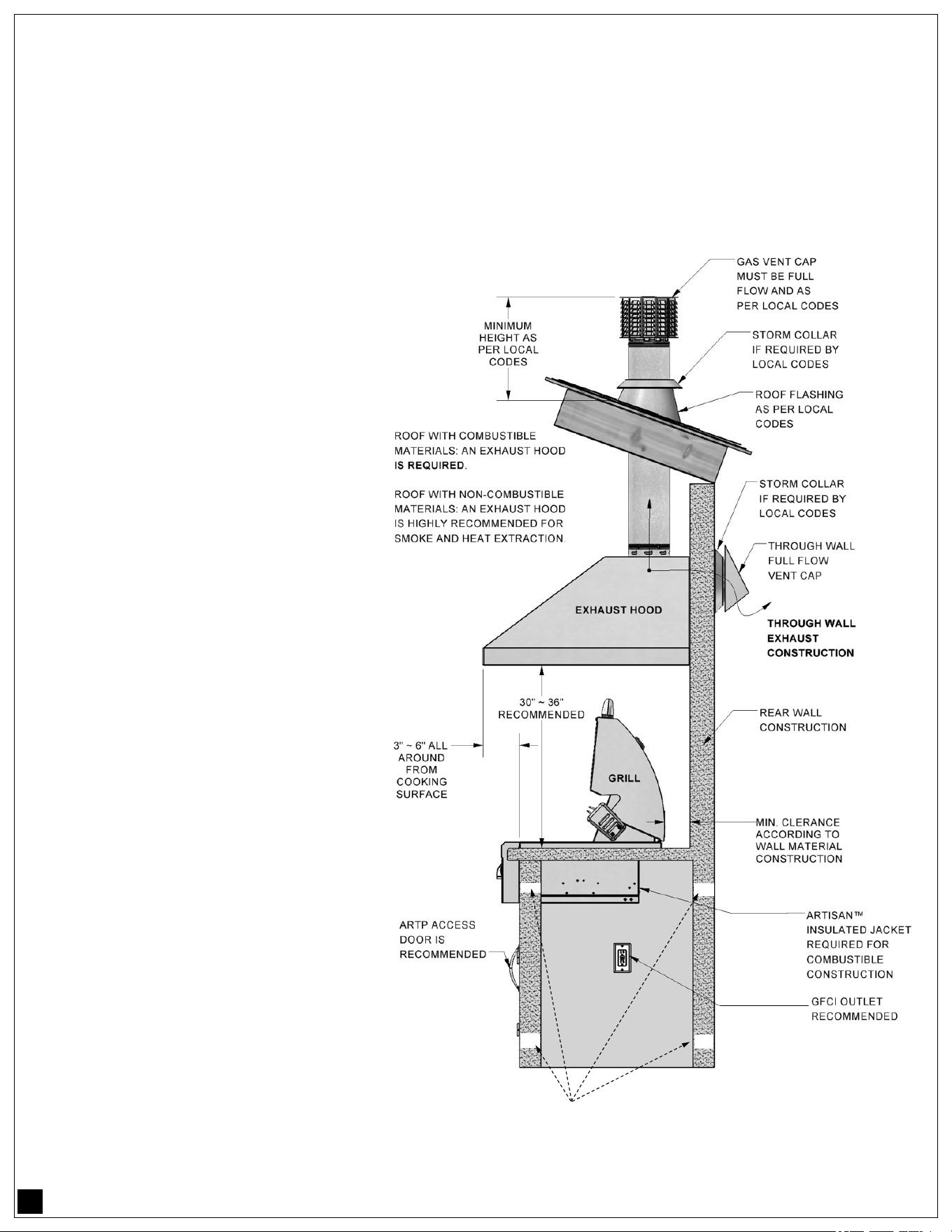
OVERHEAD CONSTRUCTION PROTECTION AND EXHAUST REMOVAL:
IMPORTANT: Never install the grill under unprotected combustible construction.
If install under any type of combustible construction, the use of an approved exhaust hood is required.
The exhaust hood provides the required protection for overhead unprotected combustible construction.
ADDITIONALLY, THE REQUIRED EXHAUST HOOD SHOULD BE:
• UL-710 or ULC-S646 approved Type I Hood for this application.
• Rated for outdoor use.
• Installed according to the manufac-
turer’s instructions.
• Have it’s own GFCI protected
branch circuit power supply.
• Have a minimum airflow of 1200
CFM’s for baffled filtered hoods or
900 CFM’s for non-baffled filtered
hoods.
• Installed at a least 30” over the
cooking surface.
• Hood intake area should be at least
3” ~ 6” bigger (side to side and front
to back) than the grill’s cooking sur-
face area.
NOTE:
Heavy and fast rising smoke is a
challenging situation for any exhaust
hood or vent system.
Constant wind or wind drafts will also
affect the ability of the exhaust hood to
catch smoke during operation.
If the BBQ grill is located in a
consistently windy area such as near
the ocean side, large lakes or on a
hillside property, a wind-break type
of construction may be required for
proper operation.
TOP AND BOTTOM VENTILATION AS PER ANSI Z21.58 CLAUSE 4.6
VENTILATION ACCORDING TO LP ENCLOSURES SHOWN ON PAGE (18)
ALSO REQUIRED FOR NG SYTEMS.
17
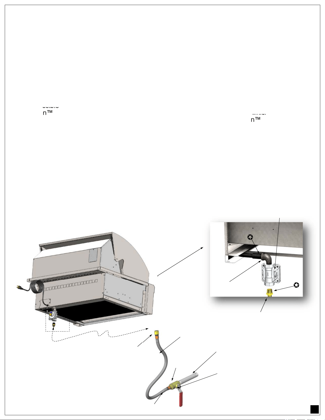
BUILT-IN APPLIANCES GAS CONNECTION - NATURAL GAS (NG)
NEVER CONNECT THE GRILL TO AN UNREGULATED GAS SUPPLY.
Before proceeding, ensure the unit is fitted for natural gas (regulator settings as well as orifices). Connect-
ing to an improper gas type will result in poor performance and increased risk of damage or injury. Installa-
tion of this cooking appliance must be made in accordace with local codes. In the absence of local codes,
this unit should be installed in accordance with the National Fuel Gas Code No. Z223.1/ NFPA 54, Natural
Gas and Propane Installation code CSA B149-1, or Propane Storage and Handling Code B149.2.
NATURAL GAS CONNECTION:
Ensure that the service pipe supplying the Grill is fitted with a shut off valve conveniently positioned and
easily accessible as an emergency gas shutoff.
Your Artisan Grill for use with natural gas comes equipped with its own regulator which MUST NOT be
removed. If this regulator needs to be replaced use only the type specified by Artisan Grill for this appli-
ance.
To connect the regulator and flex hose assembly follow the next steps:
1. Locate the regulator and gas connection point in the rear right side of your BBQ unit
2. Attach a 1/2” FPT x 1/2” MPT (male-to-female) elbow to the regulator (see diagram below).
3. Attach a 1/2” MPT x 1/2” ODF (compression flare fitting) connected to the elbow.
4. Connect to gas supply using a 1/2” Ø minimum flexible (semi-rigid) stainless steel gas hose.
The hose as well as the connectors must comply with the Standard for Connectors for Outdoor Gas Appli-
ances and Manufactured Homes, ANSI Z21.75 and CAS 6.27.
NOTE:
Locations marked with a star ()
are areas of the piping that MUST be
leaked checked after every
connection.
SHUT OFF HAND VALVE
MUST BE LOCATED IN
ACCESSIBLE AREA
INCOMING NG
GAS SUPPLY
NG STAINLESS
FLEXIBLE HOSE
TYPICAL ARTISAN BBQ (36”
MODEL SHOWN)
CONVERTIBLE GAS
PRESSURE REGULATOR
1/2” FPT X 1/2” MPT
90° ELBOW
1/2” FPT X 3/8” FLARE
BRASS FITTING
18
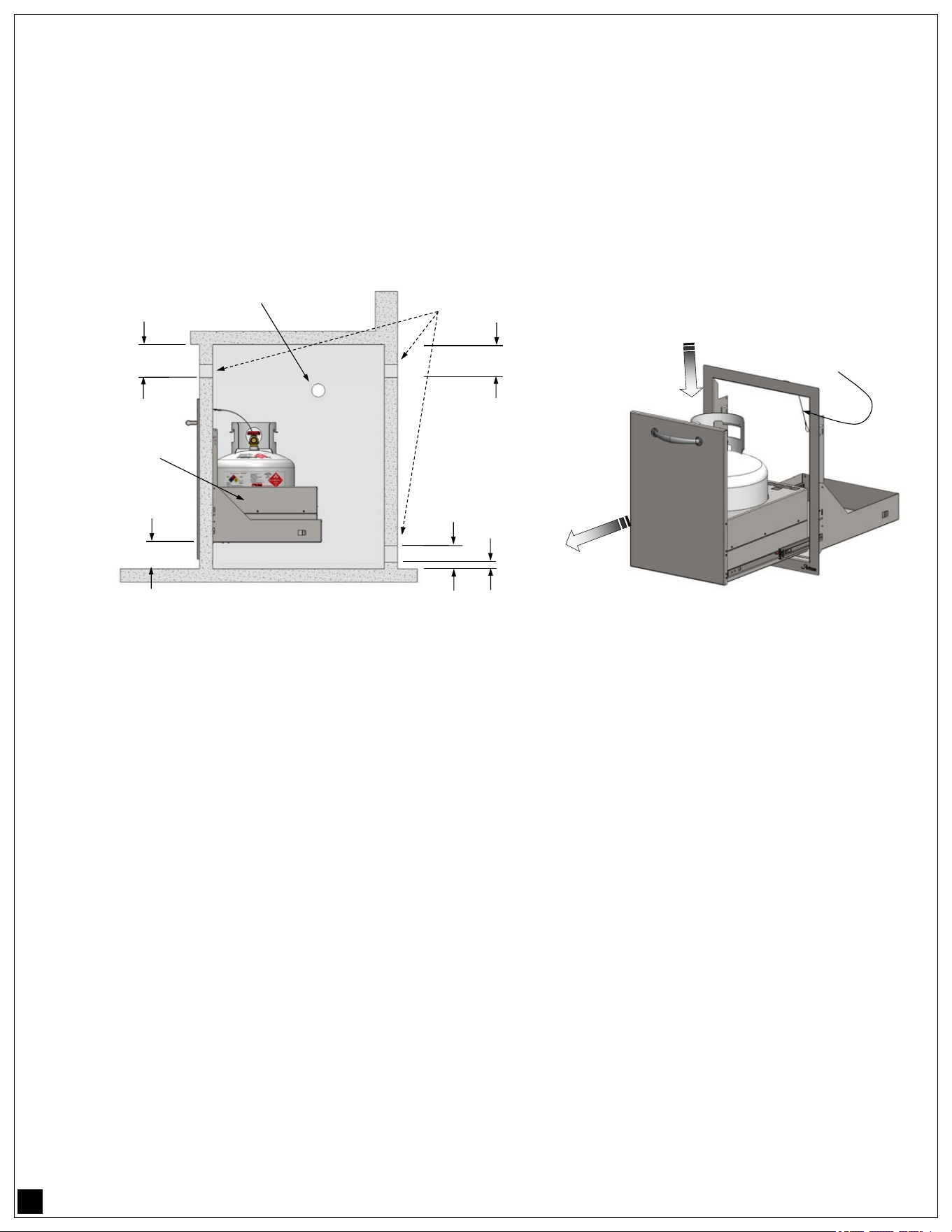
BUILT-IN APPLIANCES GAS CONNECTION - LP CYLINDER ENCLOSURES
When the outdoor cooking gas appliance is installed in a built in enclosure that requires the use of LP by
means of a gas cylinder, the use of the gas appliance tank drawer ARTP-18LPTDR-SC is highly
recommended. Refer to the ARTP-18LPTDR-SC specification sheet for installation.
The construction requirements for an LP-cylinder enclosure, should be such that the resultant construction
complies with the requirements of ANSI Z21.58 - 2022 Clause 4.6
CAUTION THE ABOVE CODE IS THE MINIMUM. MORE VENTILATION IS RECOMMENDED AS IS
ALWAYS SAFER.
TANK RETENTION POINTS:
When the ARTP-18LPTDR-SC cylinder gas drawer is installed in the built-in construction, the typical
standard 20 Lbs. (5 Gallons) LP cylinder rests on the center of the tank tray and it is retained in place
(preventing the tank from tipping sideways) by the design of the drawer itself. The cylinder can rotate freely
but can’t fall out of the drawer tray or tip over.
LP REGULATOR HOSE ASSEMBLY RETENTION:
In addition to retaining the LP tank, it is also required to properly support the LP Regulator / Hose Assembly
and prevent the unit from falling to the ground during LP tank exchanges as per ANSI Z21.58 regulations.
For this purpose, when installing the included LP Regulator and Hose Assembly, fasten the assembly to the
ARTP-18LPTDR-SC frame with the included Regulator & Hose lanyard.
ENCLOSURES FOR BUILT-IN GRILLS WITH REMOTE LP GAS SUPPLY SYSTEM
An enclosure for built in grills with remote LP gas supply systems shall be ventilated by openings at both
the upper and lower levels of the enclosure. Ventilation shall be accomplished by one of the following:
• One side of the enclosure, other than the front, shall be completely open, or
• For an enclosure having four sides, a top, and a bottom:
• At least one ventilation opening shall be provided on the exposed exterior side of the enclosure
located within 5 in (127mm) of the top of the enclosure and unobstructed. The opening’s shall have
a total free area of not less than 3 in² per 1000 Btu/h (293 W) of the largest single burner capacity.
• At least one ventilation opening shall be provided on the exposed, exterior side of the enclosure 1
in (25.4 mm) or less from the floor level and shall have a total free area of not less than 3 in²
per 1000 Btu/h (293 W) of the largest single burner capacity. The upper edge shall be no more
than 5 in (127 mm) above the floor level.
BUILT-IN CONSTRUCTION
TANK BOTTOM
2” MINIMUM
ARTP-18LPTDR-SC
LP TANK DRAWER
RECOMMENDED
BUILT-IN CONNECTION PASS THROUGH
SEALED AS PER REQUIREMENTS ABOVE.
WITHIN 5”
MAXIMUM
5”
1” OR LESS
WITHIN 5”
TOP AND BOTTOM VENTILATION AS PER ANSI Z21.58 CLAUSE 4.6
AT LEAST ONE VENT (UNOBSTRUCTED) TO EXTERIOR OF ENCLOSURE
TOP: MINIMUM 1 in²/lb (14.2 cm²/ kg) FUEL CAPACITY
BOTTOM: MINIMUM 1/2 in
²/lb (7.1 cm²/ kg) FUEL CAPACITY
ARTP-18LPTDR-SC LP TANK DRAWER
REGULATOR &
HOSE LANYARD
OPEN
DRAWER
DROP IN
LP CYLINDER

19
• Every opening shall have a minimum dimension so as to permit the entrance of a 3/16 in (4.8 mm) rod.
• Ventilation openings shall not communicate directly with other compartments of the enclosure and,
• Ventilation openings shall not be located in front of the appliance above floor level.
BUILT-IN APPLIANCE LP GAS CONNECTION TO A REMOTE LP GAS SUPPLY SYSTEMS:
A remote LP Fuel System is one with a large central LP tank that feeds the entire household. Those
systems are normally equipped with a high pressure regulator by the large LP tank and low pressure
regulators close to the home.
For this type of installation:
• DO NOT use the LP small tank regulator supplied with the unit (such as the one shown on page
10 with a QCC1 type connection).
• Connect the gas line for this type of installation directly to the unit’s convertible gas pressure
regulator in similar fashion as a typical NG gas connection (See page 17) using a flexible hose
connected to a required gas shut-off valve.
• NOTE: The convertible gas pressure regulator must be set for LP gas. (The factory pre-sets the
regulator in LP units).
• The connectors used shall the those provided with this appliance or those specified on page 6 of
this manual. Such rigid pipes, semi-flexible tubing and connectors must comply with the
Standard for Connectors for Outdoor Gas Appliances and Manufactured Homes, ANSI Z21.75
and CAS 6.27, and suitable for outside installation. The maximum length of the connection must
be 6 Ft. (1.82 m)
• The connector and primary shut-off valve should be accessible through door opening in the built-
in enclosure.
• All the rigid pipes, flexible tubing or gas connectors should be as short as possible in order to be
self supporting, otherwise they must be supported by mechanical means (ie: enclosure framing
plus additional pipe support straps or clamps) in order to minimize vibration.
• All the rigid pipes, flexible tubing or gas connectors must be protected as they pass through
openings in the compartment of the built-in enclosure according to ANSI Z21.58 2022 Clause
4.6
For all other types of rigid pipe, semi-rigid tubing, and/or connectors available to connect an appliance to a
fixed fuel piping system that can be obtained at plumbing stores, supply warehouses or home centers, the
connection must be made with by the use of a rigid pipe, semi-rigid tubing, and/or connectors that comply
with ANSI Z21.75 and CSA 6.27 standards.
BUILT-IN APPLIANCE INFORMATION FOR A REMOTE LP FUEL SUPPLY SYSTEMS TESTING:
When the Outdoor Cooking Gas Appliance is meant to be used with other than self contained LP gas
supply systems the following information should be taken into consideration during testing:
• The outdoor cooking gas appliance and its individual shut-off valve must be disconnected from
the gas supply piping system during any pressure testing of that system at test pressures in
excess of 1/2 psi (3.5 kPa)
• The outdoor cooking gas appliance must be isolated from the gas supply piping system by
closing its individual manual shut-off valve during any pressure testing of the gas supply piping
system at test pressures equal to or less than 1/2 psi (3.5 kPa).

20
F AVERTISSEMENT
PIÈCES ÉLECTRIQUES ET COMPOSANTS.
DÉBRANCHER TOUS LES BLOCS D'ALIMENTA-
TION ET LES PILES AVANT DE LES RÉPARER.
F WARNING
ELECTRICAL PARTS AND COMPONENTS
DISCONNECT ALL POWER SUPPLIES AND BATTER-
IES BEFORE SERVICING.
ELECTRICAL CONNECTIONS - LINE VOLTAGE
This Outdoor Cooking Gas Appliance has been tested in accordance with: ANSI Z21.58-2022 and CSA
1.6-2022 , The Standard for Outdoor Cooking Gas Appliances.
Please follow this instructions for your safety:
a) To protect against electric shock, do not immerse cord or plugs in water or other liquid.
b) Unplug from the outlet when not in use and before cleaning. Allow to cool before putting on or
taking off parts.
c) Do not operate any outdoor cooking gas appliance with a damaged cord or plug, or after the
appliance malfunctions or has been damaged in any manner. Contact Artisan
Grills for repair.
d) Do not let the cord hang over the edge of a table or touch hot surfaces.
e) Do not use an outdoor cooking gas appliance for purposes other than intended.
f) When connecting, first connect plug to the outdoor cooking gas appliance then plug appliance
into the outlet.
g) Use only a Ground Fault Interrupter (GFI) protected circuit with this outdoor cooking gas
appliance.
h) Never remove the grounding plug or use with an adapter of two prongs.
i) Use only extension cords with a three-prong grounding plug, rated for the power of the
equipment, and approved for outdoor use with a W-A marking
WARNINGS:
• If the information in this manual is not followed exactly, a fire or explosion may result causing property
damage, personal injury or death.
• Do not try lighting this appliance without reading the LIGHTING INSTRUCTIONS section of this manual.
For outdoor use only.
• This cooking appliance is not intended to be installed in or on recreational vehicles and / or boats.
BEFORE USING THE GRILL:
• Ensure that the grill has been leak tested. (see page 5 and 15)
• Remove any packing material.
• Read and understand the instructions in this manual.
• Electric power supply must be plugged-in at all times for barbecue operation; except during any
electrical maintenance.
NOTES CONCERNING GFCI USE AND LOCATION:
1. Do not attempt to circumvent using a GFCI receptacle, it is for your safety.
2. Ensure that the GFCI receptacle is located in an easily accessed location.
3. Follow the manufacturer’s instructions for installation and testing (must comply with local and
national codes).
21
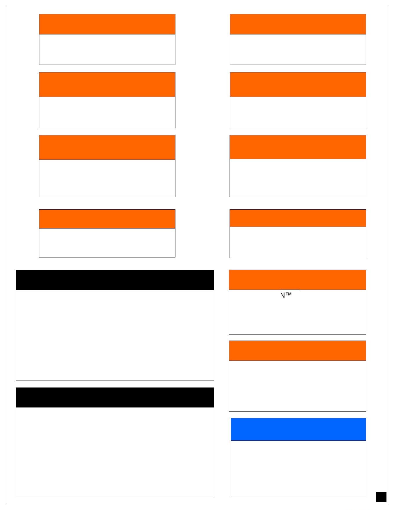
! AVERTISSEMENT
POUR UTILISATION À L'EXTÉRIEUR
NE PAS ÊTRE INSTALLÉ DANS OU SUR DES
VÉHICULES RÉCRÉATIFS ET / OU DES BA-
TEAUX.
! WARNING
FOR OUTDOOR USE ONLY
NOT TO BE INSTALLED IN OR ON
RECREATIONAL VEHICLES AND / OR BOATS.
H AVERTISSEMENT
GAZ INFLAMMABLE
DÉBRANCHER TOUS LES GAZ PROPANE OU
GAZ NATUREL DE CET APPAREIL AVANT DE
PROCÉDER À L'ENTRETIEN.
H WARNING
FLAMMABLE GAS
DISCONNECT ALL PROPANE OR NATURAL GAS
SUPPLIES TO THIS UNIT BEFORE SERVICING.
! WARNING
NEVER USE A DENTED OR RUSTED
LIQUID PROPANE TANK.
SHUT OFF TANK WHEN NOT IN USE.
! AVERTISSEMENT
N'UTILISEZ JAMAIS DE RÉSERVOIR
DE PROPANE LIQUIDE BOSSELÉ OU
ROUILLÉ. ÉTEINDRE LE RESERVOIR
LORSQU'IL N'EST PAS UTILISÉ.
! CAUTION
CYLINDERS MUST BE STORED OUTDOORS IN A
WELL VENTILATED AREA OUT OF THE REACH OF
CHILDREN.
DISCONNECTED LP CYLINDERS MUST HAVE THREADED
VALVE PLUGS TIGHTLY INSTALLED, AND MUST NOT BE
STORED IN A BUILDING, GARAGE OR ANY OTHER ENCLOSED
AREA. THE GAS MUST BE TURNED OFF AT THE SUPPLY CYL-
INDER WHEN THE UNIT IS NOT IN USE. IF THE APPLIANCE IS
STORED INDOORS, THE CYLINDER MUST BE DISCONNECTED
AND REMOVED FROM THE APPLIANCE.
! REGULATOR NOTICE
Exposure to pressures above the safety
limit of 69” WC. will permanently damage
the gas regulator requiring a replace-
ment.
OVER PRESSURE DAMAGE IS NOT COV-
ERED BY YOUR ARTISAN WARRANTY
! MISE EN GARDE
LE CYLINDRE DOIT ÊTRE STOCKÉ À L'EXTÉRIEUR
DANS UN ENDROIT BIEN VENTILÉ ET HORS DE LA POR-
TÉE DES ENFANTS.
DÉBRANCHER LES BOUTEILLES DE LP DOIVENT AVOIR DES
BOUCHONS DE VALEUR VISSÉS HERMÉTIQUEMENT INSTAL-
LÉS, ET NE DOIVENT PAS ÊTRE STOCKÉS DANS UN BÂTI-
MENT, GARAGE OU TOUT AUTRE ESPACE FERMÉ. LE GAZ
DOIT ÊTRE ARRÊTÉ AU NIVEAU DU CYLINDRE D'ALIMENTA-
TION LORSQUE L'APPAREIL N'EST PAS UTILISÉ. SI L'APPA-
REIL EST ENTREPOSÉ À L'INTÉRIEUR, LE CYLINDRE DOIT
ÊTRE DÉBRANCHÉ ET RETIRÉ DE L'APPAREIL.
! WARNING
YOUR ARTISAN GRILL’S PRESSURE
REGULATOR HAS A MAXIMUM INPUT
PRESSURE OF 14” WC. (OR APPROX.
.5 PSI) , AND A SAFETY LIMIT OF 69”
WC. (2.5 PSI).
! AVERTISSEMENT
VOTRE RÉGULATEUR DE PRESSION
ARTISAN GRILLADES A UNE PRES-
SION D'ENTRÉE MAXIMALE DE 14"
WC (OU ENVIRON 0,5 PSI), ET UNE
LIMITE DE SÉCURITÉ DE 69" WC (2,5
PSI).
! WARNING
DO NOT ATTEMPT TO LIGHT THE
GRILL IF THE ODOR OF GAS IS
PRESENT.
! AVERTISSEMENT
N'ESSAYEZ PAS D'ALLUMER LE
GRIL SI L'ODEUR DE GAZ EST
PRÉSENTE.
22
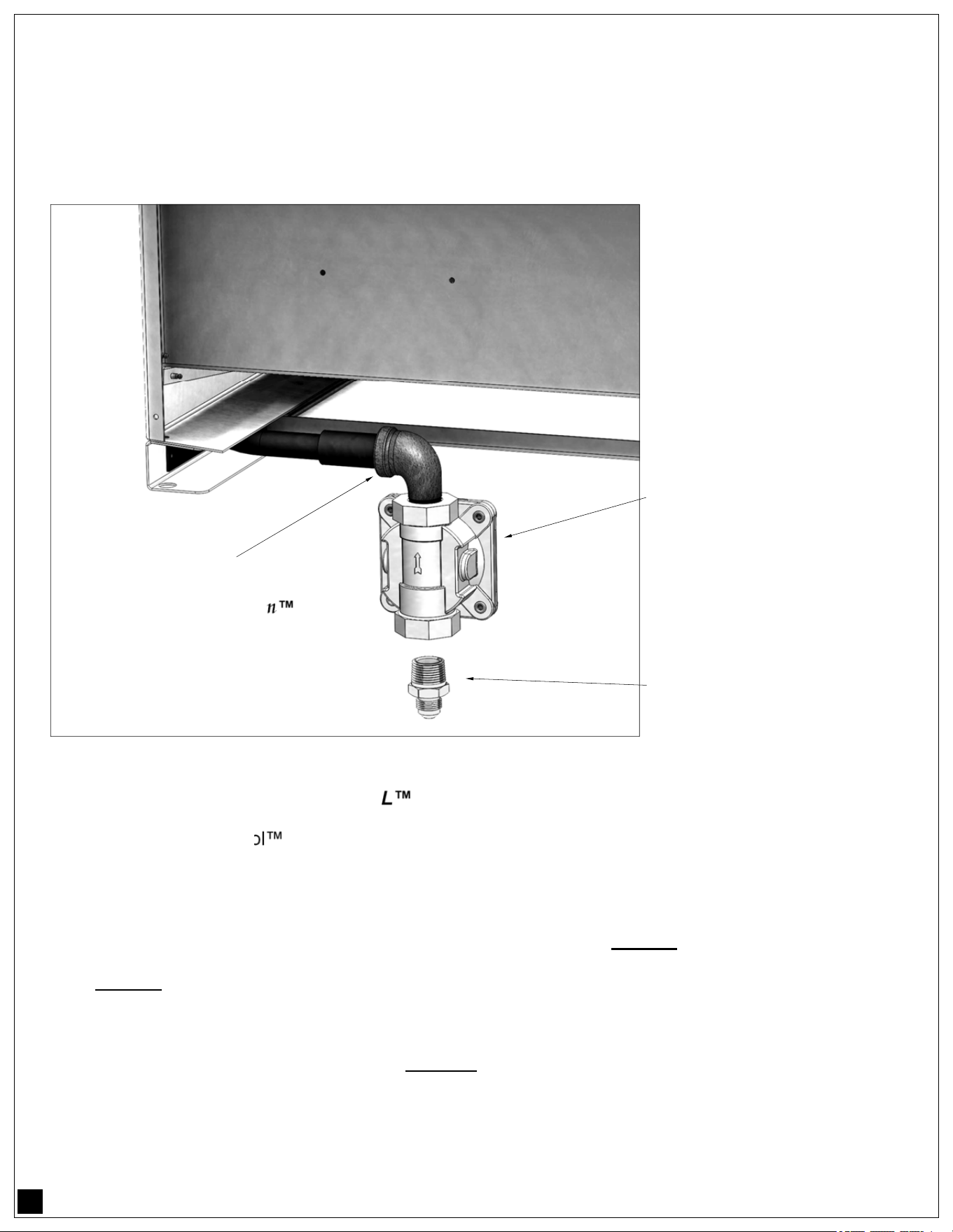
REGULATOR SUPPLY CONVERTION:
Attach inlet elbow (1/2” Ø black pipe elbow) to gas manifold (see illustration below). Locate and
attach the hose regulator with 1/2” x 3/8 nipple (fitting hose adaptor) using gas approved gas plumbing
seal of yellow Teflon® tape. (This step only applies to NG to LP conversion).
PRESSURE
REGULATOR
FITTING—HOSE ADAPTOR
1/2ӯ NPT x 3/8ӯ COMP.
(NG TO LP ONLY!)
ROTATE ELBOW IF NECESSARY
(PROVIDED BY Artisan )
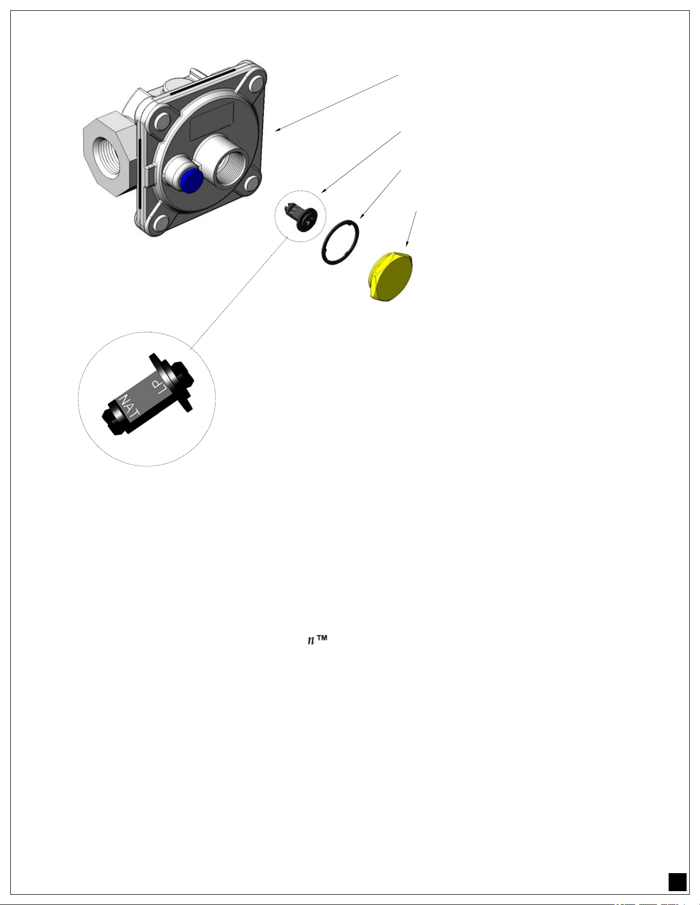
PRESSURE ADJUSTMENT: (MAXITROL UNITS ONLY)
1– To convert the Maxitrol
pressure regulator from NG to LP (or vice-versa) , remove the brass cap
located on the large round dome of the regulator body. The cap has a sealing washer; do not lose or
damage this sealing washer as it is required for a gas tight seal. (see illustration on page 12)
2– Located on the cap is also a black plastic plunger. This plunger provides the correct pressure to a
spring located inside the body of the regulator. It is necessary to reverse the direction of the plunger
so it provides the right amount of pressure to the spring inside the body of the regulator.
To reverse the plunger pull it out of the brass cap by pushing it sideways until it snaps and pops out.
3– The plunger is labeled “NAT” or “LP” for natural gas or liquid propane. (see illustration on page 12).
The regulator is set to the correct pressure according to the way the plunger faces the regulator
body. If the plunger label reads ”NAT” towards” the body of the regulator , it will be set for natural
gas. If it reads “LP” it will be set for liquid propane.
23
Pressure Regulators cont.
PLUNGER DETAIL:
The regulator plunger is labeled “NAT” for Natural gas or “LP”
for liquid propane. (The “LP” side has a wide disk on the end.)
The side facing the body of the regulator determines what
use is the regulator set for.
Example: The image above is showing a regulator set for nat-
ural gas.
4– Once the regulator plunger has been reversed for it’s appropriate use and snapped back into the brass
cap, re-install the cap with the sealing washer back into the body or the regulator.
The regulator pressure conversion is complete.
LEAK TESTING:
GENERAL:
Although all gas connections on your Artisan Grill are leak tested at the factory prior to shipment, a
complete gas tightness check must be performed at the installation site due to possible mishandling in
shipment, or excessive pressure unknowingly being applied to the unit.
Periodically check the whole system for leaks, or immediately check if the smell of gas is detected.
BEFORE TESTING:
• Make sure that all packing material is removed from the grill.
• Make sure the burner tie-down straps are removed from the unit.
• Do not smoke while leak testing.
• Never leak test with an open flame.
• Make a soap solution of one part liquid detergent and one part water for leak testing purposes.
• Apply the solution to the gas fittings by using a spray bottle, or brush.
• For LP units, always check with a full cylinder.
PRESSURE REGULATOR
BODY (DOME SIDE)
PLUNGER
SEALING WASHER
BRASS CAP

24
READ THIS CARE AND USE MANUAL CAREFULLY AND COMPLETELY BEFORE USING YOUR
GRILL TO REDUCE THE RISK OF FIRE, BURN HAZARD OR OTHER INJURY. KEEP THIS
MANUAL FOR FUTURE REFERENCE.
When properly cared for, your Artisan Grill will give safe, reliable service for many years. However, extreme
care must be used since the grill produces intense heat, which can increase accident potential. When using this
appliance, basic safety practices must be followed, including but not limited to the following:
• Begin by ensuring proper assembly. A qualified technician should perform all other service.
• All other service should be referred to and performed by a qualified technician.
• For personal safety, wear proper apparel while barbecuing.
• Loose fitting garments or sleeves should never be worn while using this appliance.
• Some synthetic fabrics are highly flammable and should not be worn while cooking.
• Never let clothing, pot holders or other flammable materials come in contact with or too close to any grate,
burner or hot surface until it has cooled down sufficiently. Fabrics may ignite and result in personal injury.
• Use only dry potholders: moist or damp potholders on hot surfaces may cause personal burns from steam. Do
not use a towel or bulky cloth in place of potholders. Do not let potholders touch hot portions of the grill rack.
• Only certain types of glass, heatproof glass ceramic, earthenware, or other glazed utensils are suitable for grill
use. These types of materials may break with sudden temperature changes. Use only on low or medium heat
settings and according to their manufacturer’s directions.
• Grease is flammable. Let hot grease cool before attempting to handle it.
• Avoid letting grease deposits collect in the bottom of the grill by cleaning the grease tray often. Never while
grill is on or hot from recent use; pan will not come out.
• Do not use aluminum foil to line the grill racks, nor to line the drip tray. This can severely upset combustion
airflow or trap excessive heat in the control area. The result of this can be melted knobs, igniters and
increased chance of personal injury. Never grill without the drip pan in place and pushed all the way to the
back of the grill. Without the drip pan, hot grease can leak downward creating a fire or explosion hazard.
• Children should not be left alone or unattended in an area where the grill is being used. Never allow them to
sit, stand or play on or around the grill. Do not store items of interest to children around or below the grill or in
the cart. Never allow children to crawl inside of the cart.
• Do not heat unopened food containers that may cause the container to build-up pressure and burst.
• Protect your hand when opening a hot grill lid. Never lean over an open hot grill.
• When lighting a burner, always pay close attention to what you are doing. Be certain you are
depressing the correct button, labeled for the igniter.
• When using the grill: do not touch the grill rack, burner grate, hood or immediate surrounding area as
these areas become extremely hot and could cause burns. Use only the handles and knobs provided
for operation of the grill.
• For proper lighting and performance of the burners keep the ports clean. It is necessary to clean
them periodically for optimum performance. The burners will only operate in one position and must
be mounted correctly for safe operation.

25
• Clean the grill with caution. Avoid steam burns; do not use a wet sponge or cloth to clean the grill while
it is hot. Some cleaners produce noxious fumes or can ignite when applied to a hot surface.
• INSECT WARNING: Spiders and insects can nest in the burners of this and other grills, and cause the
gas to flow from the front of the burner. This is a very dangerous condition, which can cause a fire to
occur behind the valve panel, thereby damaging the grill and making it unsafe to operate. Inspect the
grill at least twice a year.
• Be sure all grill controls are turned off and the grill is cool before using any type of aerosol cleaner on or
around the grill. The chemical that produces the spraying action could, in the presence of heat, ignite or
cause metal parts to corrode.
• Do not use this appliance under overhead combustible surfaces. Use only in well ventilated are-
as. Do not use in buildings, garages, sheds, breezeways or any enclosed areas.
• Keep the area surrounding the grill free from combustible materials, trash, or combustible fluids and
vapors such as gasoline or charcoal lighter fluid. Do not obstruct the flow of combustion gases and ven-
tilation airways.
• Keep the back of the cart free and clear from debris.
• If the unit is stored indoors ensure that it is cool. If propane is used, the cylinder must be unhooked and
the propane cylinder stored outside in a well-ventilated area, out of reach of children.
• Never use the grill in windy conditions. If located in a consistently windy area, oceanfront, mountaintop,
etc... a windbreak will be required. Always adhere to the specified clearances.
• Keep any electrical supply cord, away from the heated areas of the grill.
• Do not use the grill for cooking excessively fatty meats or products, which promote flare-ups.
PREHEATING THE GRILL:
U-BURNERS:
Preheating the grill is important for best performance. To preheat the grill when cooking with the U-
burners, close the hood after lighting the burners as described above. Set the grill control knobs on “HI”
for 15 minutes.
IR-BURNERS:
Preheating the IR burners is important to protect them from food drippings. After lighting the IR burners
as described above, allow to preheat on “ON” for four minutes before beginning to grill.
If your grill is equipped with a SEAR-ZONE
IR BURNER, light and preheat the U-BURNERS first, then
light and preheat the SEAR-ZONE IR BURNER.
ROTISSERIE BURNER:
Light the rotisserie burner as described in the lighting instructions. Once lit, the rotisserie burner will
reach cooking temperatures in about 1 minute.

26
BURNER ADJUSTMENTS:
NOTE: grills are available with both U-burners and IR burners. The following instructions apply
only to the U-burners. IR burners do not require adjustment and need only be checked visually for proper
performance. On high, an IR burner should glow red evenly over its entire surface.
U-BURNER AIR ADJUSTMENT:
Each grill burner is tested and adjusted at the factory prior to shipment; however, variations in the local
gas supply, elevation and other factors might make it necessary to adjust the burners. The flames of the
burners should be visually checked and compared with figures on next page.
If any of these conditions exist, check if dirt, debris, spider webs, etc., are blocking the air shutter or burn-
er ports. Proceed with air shutter adjustment.
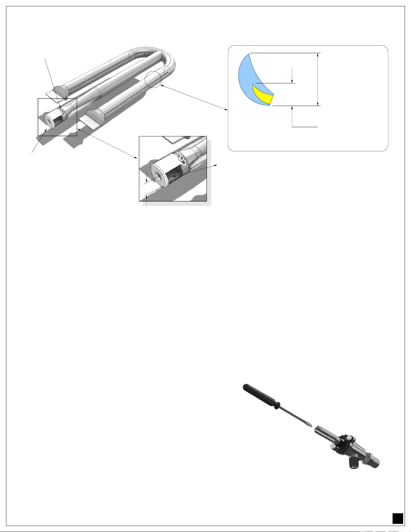
AIR SHUTTER ADJUSTMENT:
A sheet metal cap at the inlet of the burner called the “AIR SHUTTER” regulates the amount of air that
enters into the burner for combustion.
The air shutter is locked in place by a screw, which must be loosened prior to lighting the burner for ad-
justment. The air shutter adjustment screws are accessible with a screwdriver by removing the burner.
Loosen the screw of the air shutter. Reinstall the burner. Make certain that the burners are sitting properly
on the orifices taking care not to move or damage the igniter electrode.
Light the burners and adjust according to the following directions:
• Turn the valve on “HI”, light the burner and allow it to “WARM UP” for 10 minutes.
• If the flame is yellow, indicating insufficient air, turn the air shutter counter-clockwise to
allow more air to the burner. *Caution, see note below.
• If the flame is noisy and tends to lift away from the burner, (WITH THE BRIQUETTE
TRAYS IN POSITION) indicating too much air, turn the air shutter clockwise to reduce
the amount of air to the burner.
• Retighten the locking screw of the air shutter cap.
*NOTE: Be careful, as the burner may be or will become very hot after lighting it.
Flames should be blue and stable with no yellow tips, excessive noise or lifting.
! WARNING
NEVER ADJUST THE BURNER SO LOW
THAT IT MAY GO OUT DURING USE. DO
NOT OPERATE THE GRILL WITH THE LOW
HEAT SCREW REMOVED.
GAS CAN ESCAPE AND CAUSE A
POTENTIALLY HAZARDOUS CONDITION.
! AVERTISSEMENT
NE JAMAIS AJUSTER LE BRÛLEUR SI BAS QU'IL
PEUT S'ÉTEINDRE PENDANT L'UTILISATION.
N'UTILISEZ PAS LE GRIL AVEC LA VIS À
CHALEUR BASSE RETIRÉE.
LE GAZ PEUT S'ÉCHAPPER ET PROVOQUER
UNE CONDITION POTENTIELLEMENT
DANGEREUSE.
27
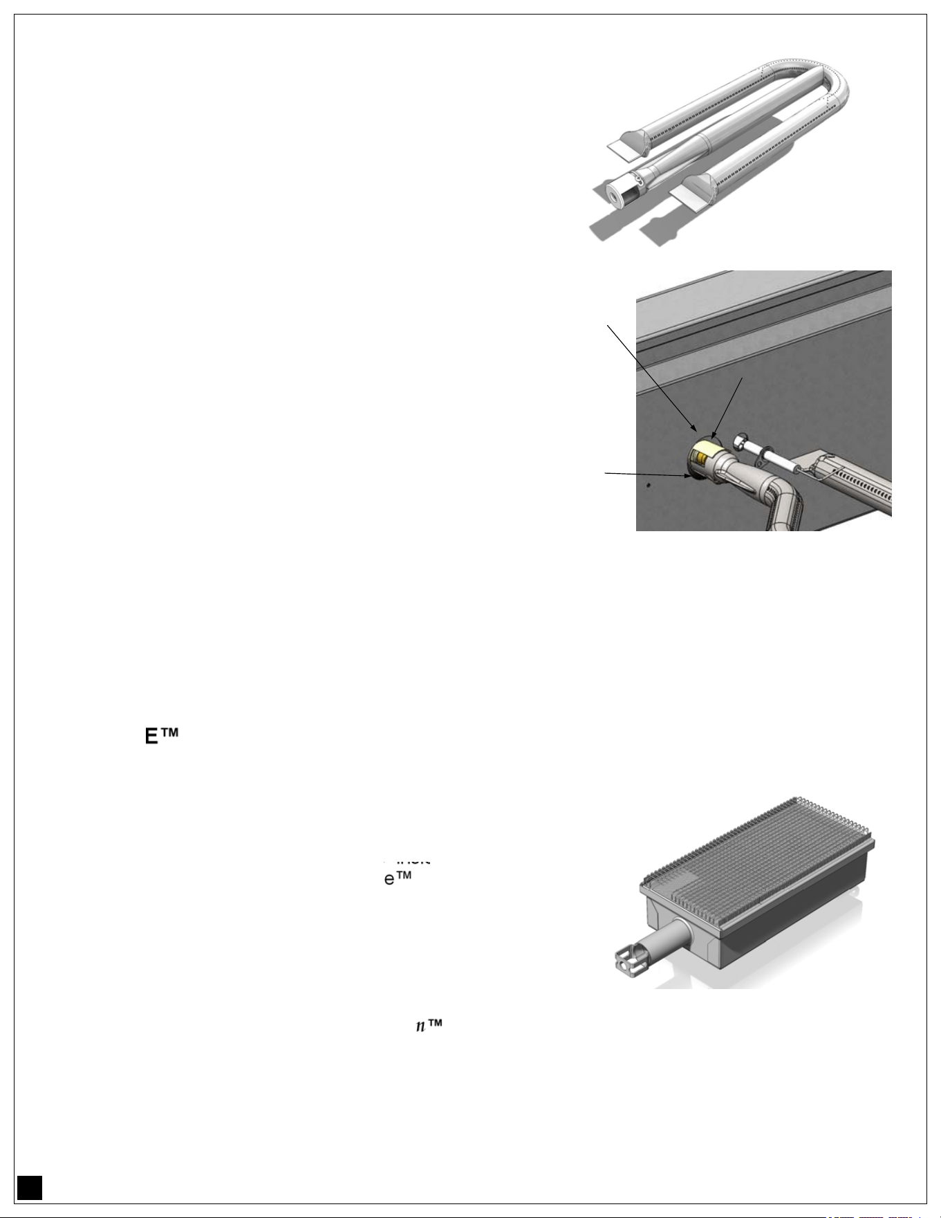
LOW HEAT SETTING ADJUSTMENT:
NOTE:
THE LOW HEAT SETTING ON YOUR GRILL IS PRESET AT THE FACTORY. ADJUST ONLY IF ALTI-
TUDE OR ENVIRONMENTAL FACTORS ARE CAUSING POOR, LOW HEAT, PERFORMANCE.
ADJUSTMENT STEPS:
1. Follow lighting instructions by setting the control
knob on “HI” and allow the burner to preheat for 10
minutes.
2. Turn the control knob to “LOW” and wait for the
burner temperature to drop and stabilize.
3. Attempting adjustment at any setting other than
LOW can create a dangerous condition.
4. Remove knob by pulling straight away from control
panel.
5. Insert a small blade screwdriver into the valve stem
to begin the adjustment.
6. Turn counter-clockwise to INCREASE the low heat
flame while using pliers to hold the stem securely.
7. Adjust the flames so the burner is fully lit around the
perimeter when the knob is in the LOW position. Once
proper adjustment is reached, reattach the knob by
pushing onto stem.
AIR SHUTTER
ADJUSTMENT CAP
LOCKING SCREW
U-BURNER
1” MAXIMUM
3
/
8
” MAXIMUM
FLAME SIZE
AIR SHUTTER APPERTURE IS FACTORY
SET TO APPROXIMATELY 1/2” FOR LP &
5/8” FOR NG - MINOR ADJUSTMENTS MAY
BE NECESSARY DUE TO FACTORS SUCH
AS HIGH ALTITUDE LOCATIONS.
28
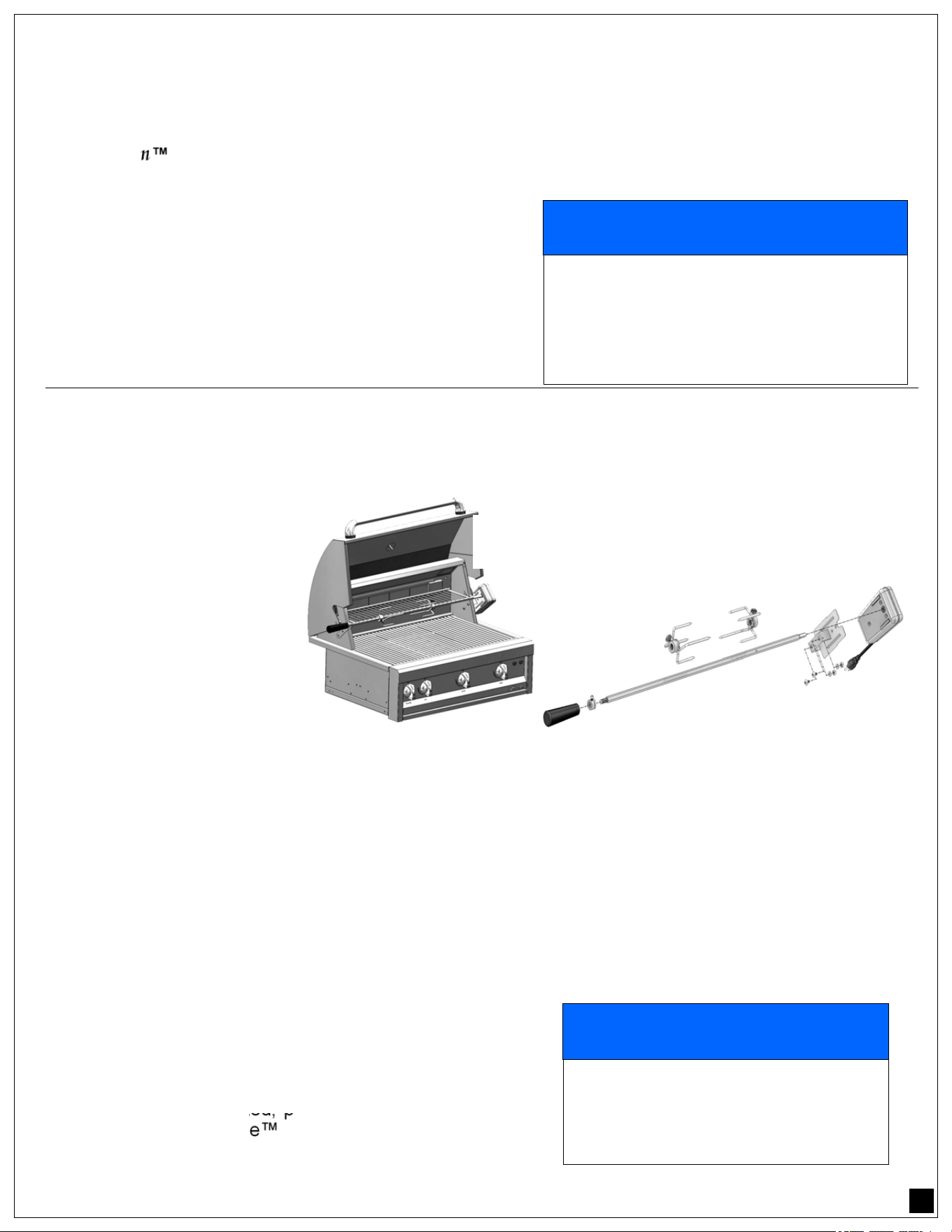
OPERATING THE GRILL:
U-BURNERS:
The grill burners encompass the entire cooking area and
are side ported to minimize blockage from falling grease
and debris.
Above the burners there are stainless steel briquette
trays with ceramic briquettes. The briquette tray is a
fundamental part for the performance of the grill. Do not
cook on the grill without them.
Make sure the briquette tray is installed properly before
lighting the burner. Each grill burner has its own igniter.
The burners are locked in the proper position within the
barbeque unit by the inlet port where the valve orifice
stem is located, the shutter adjustment screw notch and
the rear mounting bracket at the back of the grill cavity.
USING THE GRILL:
Grilling requires high heat for searing and proper
browning. Most foods are cooked at the “HI” heat setting
for the entire cooking time. However, when grilling large pieces of meat
or poultry, it may be necessary to turn the heat to a lower setting after the initial browning. This method will
cook the food through without burning the outside. Foods cooked for a long time or basted with a sugary
marinade may need a lower heat setting near the end of the cooking time.
NOTE: The hot grill sears the food, sealing in the juices. The longer the preheat period, the faster the meat
browns and the darker the sear marks. Place the food on the grill and cook to the desired brown level.
Adjust heat setting, if necessary. The control knob may be set to any position between “HI” and “LOW”.
DO NOT leave the grill unattended while cooking.
SEAR-ZONE
- IR BURNERS:
An IR grill works by producing intense heat which quickly sears the
meat. Searing locks in flavor and juices while allowing the outer
surface to absorb smoke and food aroma that is produced as
grease and drippings are vaporized by the burner. The result is a
crisp, flavorful outside with a tender, juicy inside. Just the result
you want with most grilled foods. Sear-Zone
burners are located
in their proper position by the inlet port and the rear bracket
support of the burner area.
USING THE GRILL:
Grilling requires high heat for searing and proper browning. The
intense infrared heat produced by your Artisan Grill meets these requirements perfectly. Meat is cooked
evenly throughout, while juices grease and food particles are vaporized upon contact with the burner,
giving added flavor to your food.
LOCATING
NOTCH
INLET PORT
BURNER
SHUTTER
29
NOTE: The hot grill sears the food, sealing in the juices. Proper preheating browns the meat and produces
darker sear marks. Place the food on the grill and sear both sides as recommended on the “Infrared Grill-
ing Tips” section on page 30. DO NOT leave the grill unattended while cooking.
ROTISSERIE BURNERS:
Your
Artisan Grill is capable of performing back burner rotisserie cooking. The location of the rear
burner allows the placement of the rotisserie basting pan (not included) beneath the food to collect juices
and drippings for basting and gravy. To flavor the contents of
the basting pan, you can add herbs, onion, garlic,
or spices.
To assure that an IR burner is lit, very carefully place your
hand 8-10 inches away from the burner surface. If you do
not feel the heat of the burner, shut off control knob, wait five
minutes, and attempt to relight.
ROTISSERIE MOTOR:
The rotisserie motor is capable of turning up to a 25 Lb. cut of meat or poultry, with a maximum diameter of
10”. The rotisserie motor is electrically grounded by it’s own plug, therefore the motor must be installed in
accordance with local codes or, in the absence of local codes, with the National Electrical Code, ANSI/
NFPA 70-1990.
SKEWER:
The skewer for the rotis-
serie is assembled into
the skewer coupler
(located in the motor) by
placing the pointed end
into the square opening
of the coupler. The oth-
er end of the skewer
(round shaft end) rests
in the slot in the oppo-
site end of the barbecue.
To load the skewer, slide the meat holders with the prongs facing towards the center the skewer bar. Push
the skewer through the center of the food, and then slide the second meat holder (prongs toward the food)
onto the skewer.
Center the product to be cooked on the skewer then push the meat holders firmly together. Tighten the
thumb nuts of the meat holders with pliers. It may also be necessary to wrap the food with butcher’s string
(never use nylon or plastic string) to secure any loose portions. Once the food is secure, insert the skewer
into the coupler.
Start the motor with the switch located on the end of the motor.
ROTISSERIE BASTING PAN:
Place a pan onto the grill racks (or, if necessary, directly onto
the briquettes if the grill racks are removed to accommodate
large cuts of meat). This pan is required to catch drippings
from the meat being cooked, preventing grease build-up on
the briquettes or Sear-Zone IR Burner.
ROTISSERIE BASTING PAN:
! NOTICE
AVOID WATER DAMAGE TO BURNER NEVER
ALLOW WATER TO CONTACT THE IR BURNER
AS DAMAGE TO THE CERAMIC PANEL WILL
RESULT.
WATER DAMAGE IS NOT COVERED BY YOUR
ARTISAN WARRANTY
! NOTICE
ALWAYS USE BASTING PAN WITH
ROTISSERIE TO KEEP DRIPPINGS
OFF BURNERS AND BRIQUETTES.
DO NOT USE WHILE GRILLING.
ATTACH ROTISSERIE
MOTOR TO EITHER END
30
ROTISSERIE GENERAL COOKING INSTRUCTIONS:
As a general rule, rotisserie cooking will take 15 ~ 20 minutes per pound of meat. Keep the hood closed as
much as possible to improve performance.
INFRARED GRILLING TIPS:
Even for an experienced chef, infrared cooking can, at first, present a bit of a challenge. By following these
simple tips, you will soon be producing juicier, more flavorful foods than you have ever experienced before.
As a general rule, foods will cook in less time than they would take on an
ordinary grill. By turning food frequently (approximately every 2 minutes), excessive charring is simply
avoided.
Artisan
RECOMMENDS THAT YOU TURN FOOD BEING GRILLED ON A SEAR
ZONE IR-BURNER EVERY TWO MINUTES DURING THE COOKING PERIOD.
NEVER ALLOW FOOD TO COOK MORE THAN 2 1/2 MINUTES WITHOUT TURNING.
SEARING IS THE KEY:
An infrared grill works by producing intense heat which quickly sears meats. Searing locks in flavor and
juices while allowing the outer surface to absorb smoke and food aroma that is produced as grease and
drippings are vaporized by the burner. The result is a crisp, flavorful outside with a tender, juicy inside.
Just the result you want with most grilled foods.
HOW TO GRILL WITH IR:
Properly pre-heat the grill by following the lighting instructions on page 7 and 8. Place food on grill grids
and turn every 2 to 2 1/2 minutes until food is cooked to desired taste. Do not let food cook more than 2 1/2
minutes without turning. Perfect cross sear marks can be made by rotating food 90° at each turn.
APPROXIMATE SEAR-ZONE COOKING TIMES:
These are recommended times only. Due to the variations on the cuts of meats and personal taste, your
cooking times may be different. Use your discretion when cooking with Artisan
Sear-Zone IR-
Burners.
STAINLESS STEEL CARE:
Stainless Steel is widely used for catering and residential kitchen equipment because of its strength, its
ability to resist corrosion and its ease of cleaning. In fact, stainless steel ranks alongside glass and new
china in terms of “ease of cleaning” and in percentage removal of bacteria during washing. As a result of
these virtues, the metal is often taken for granted and it is assumed that no problems will arise during its
usage. However, some care is required to ensure that the stainless steel can live up to this reputation.
FOOD ITEM APPROXIMATE COOKING TIME
(MINUTES)
RARE MEDIUM WELL
HAMBURGER -1/2” THICK 4 5 6
STEAK - 1” THICK” 6 8 10
CHICKEN BREAST (BONELESS) 8 ~ 10
CHICKEN BREAST (BONE-IN) 20 ~ 24

31
DAY TO DAY CARE:
To maintain the original appearance of your Artisan Grill, a regular cleaning routine should be
carried out using the following guidelines:
1. After use, following the safety precautions detailed on page 4 and 5, wipe the Grill with
a soft damp soapy cloth and rinse with clean water, preferably warm/hot water. This
should remove most substances encountered during the grilling process.
2. For more tenacious deposits, including oil, grease and water-borne deposits, use a multi
purpose cream cleanser and apply with a soft damp cloth. Rinsing with fresh water, as
described above, should follow as a last step.
3. For really stubborn dirt or burned-on grease, a nylon-scouring pad may be used in
conjunction with the cream cleanser. On no account should “wire wool” pads be used
unless they are made of stainless steel.
4. Harsh abrasives and scouring materials should not be used for cleaning stainless steel
as they will leave scratch marks in the surface and damage the appearance of the Grill.
Likewise do not use wire brushes, scrapers or contaminated scouring pads.
5. Your
Artisan Grill has a directional polished grain, any cleaning with abrasives
should be carried out along this grain direction and not across it.
6. After use, always remove wet cleaning aids (such as cloths, pads, containers) from the
surface, to avoid formation of water marks or stains.
7. If necessary, dry the Grill after use with a soft dry cloth or towel.
If the preceding guidelines are adhered to, your
Artisan Grill should offer excellent life and should
live up to its reputation of being “stainless”.
Neglect of this practice, however, can lead to deterioration of the surface and, in some extreme cases,
corrosion of the steel itself. The two most common types of corrosion that may be encountered,
particularly on stainless steel, are rust marks and pitting of the surface.
RUST-BROWN MARKS:
The rust marks are more likely to be the result of small particles of “ordinary-steel” which have become
attached to the surface; these have subsequently rusted in the damp environment. The most common
source of such particles is from “wire-wool” scouring pads, but contamination may also occur from
carbon steel utensils and old cast iron water supply pipes.
These brown marks are only superficial stains, which will not harm the Grill; they should be removable
using a soft damp cloth and a multi-purpose cream cleanser.
Occasionally, it may be necessary to resort to a proprietary stainless steel cleanser, to return the surface
of the Grill to its original condition. To avoid re-occurrence of any “rust-staining” it is essential that the
source of the contamination be eliminated.
PITTING:
Another form of corrosion, which occasionally occurs in stainless steel, is pitting of the surface. The
reason for this corrosive attack can usually be attributed to certain household products, for example:
Bleaches:
Most common domestic bleaches & sterilizing solutions contain chlorine in the form of sodium
hypochlorite. If used in concentrated form, bleaches can attack the stainless steel, causing pitting of the
surface. They should always be used to the strengths prescribed by the manufacturer and should be
thoroughly rinsed off with clean water immediately after use. All cleaning agents containing hypochlorite
are unsuitable for long term contact with stainless steel and, even when used in the highly diluted form,
they can produce pitting under certain conditions.
Foodstuffs:
In general stainless steel is fully resistant to all foodstuffs in common use. Only in isolated cases, such
as when concentrated salt and vinegar mixtures are allowed to remain in contact with the steel for a long
period, can any surface marking result.
32
CARE & MAINTENANCE OF YOUR GRILL:
GRILL RACK:
The easiest way to clean the round wire grill racks is immediately after cooking is completed and after
turning off the flame. Wear a barbecue mitt to protect your hand from the heat and steam. Dip a brass
bristle barbecue brush in hot soapy water and scrub the hot grill rack. Dip the brush frequently in the bowl
of water. Steam, created as water contacts the hot grill, assists the cleaning process by softening any food
particles. The food particles will fall and burn.
If the grill is allowed to cool before cleaning, then cleaning will
be more difficult.
The V-grate used for the IR burner will primarily self-clean
during the 5 minute IR burner cleaning period (Rear IR-
Burner cleaning below). After the grate has cooled, remove
it from the grill and brush off burned debris.
STAINLESS STEEL:
The Grill is made from commercial quality type 304 non-
rusting and non-magnetic stainless steel, and the cleaning
information shown on Page 38 should be followed.
DRIP TRAY:
The drip tray should be cleaned after every usage of the grill.
After allowing the grill to cool completely, remove the drip tray
by pulling it out from the grill until it stops, then lifting the front
edge about 45° to remove from grill.
Reinstall by placing rear of tray into guides, then lifting front
edge 45° to re-insert the tray. Slide completely into the grill.
GRILL BURNERS:
Before removing the burners, make sure that the gas supply is
OFF and the control knobs are in the OFF position. Allow grill
to cool completely, then lift off the grill racks and briquette
trays. To remove burners, lift the rear of the burner out of the
bracket.
Angle the burner slightly to clear the igniter electrode and
opening at the front of the grill. Slide burner straight off the
orifice tip. Great care should be used when installing a burner,
as it must be correctly centered and secured on the orifice
before any attempt is made to relight the grill. The burner
should lie flat and not have any side-to-side movement.
Frequency of cleaning will depend upon grill use.
U-BURNER CLEANING:
Clean the exterior of the burner with a brass wire brush. Clear
any stubborn scale with a metal scraper. Clear any clogged
ports with a thin wire. Never use a wooden toothpick as it may
break off and clog the port. Shake out any debris through the
air shutter. Use a flashlight to inspect the burner inlet to
ensure it is not blocked, if obstructions can be seen, use a stiff
wire to clean out the burner throat.
! NOTICE
NEVER CLEAN THE V-GRATE WITH ANY
TYPE OF LIQUID WHILE IT IS ON THE
GRILL. LIQUID CAN PERMANENTLY
DAMAGE THE IR-BURNER.
! WARNING
DO NOT ALLOW EXCESS GREASE OR
LIQUIDS TO ACCUMULATE IN THE DRIP
TRAY AS THIS WILL CREATE A FIRE
HAZARD.
! AVERTISSEMENT
NE PERMETZ PAS D'EXCESSER UNE
GRAISSE OU DES LIQUIDES À ACCU-
MULER DANS LE BANDE DE DÉCHARGE,
CELUI-CI CRÉER UN RISQUE D'IN-
CENDIE.
! WARNING
DO NOT ATTEMPT TO REMOVE THE
DRIP TRAY DURING USE OR WHILE IT IS
HOT AFTER USING THE GRILL.
! AVERTISSEMENT
NE TENTUREZ PAS DE RETIRER LE BANDE
DE DÉCHARGE PENDANT L'UTILISATION OU
QU'IL SOIT CHAUD APRÈS UTILISATION DU
GRILL.

33
IR-BURNER CLEANING:
AFTER EACH USE, IT IS NECESSARY TO BURN ALL IR
BURNERS WITH THE HOOD OPEN FOR AT LEAST FIVE
MINUTES TO VAPORIZE ANY FOOD DRIPPINGS OR
PARTICLES.
It may occasionally be necessary to brush,
blow or vacuum accumulated ash from the burner surface.
Do so carefully and only when the burner is cool.
ORIFICE CLEANING:
With the burner removed, remove the orifice and shine a flashlight through the openings to ensure there is
no blockage. Use a needle to clear any debris. Be extremely careful not to enlarge the hole or break off the
needle.
TO REASSEMBLE THE BURNERS:
Replace the burner by sliding the air shutter over the brass orifice, centering it in the hole and resting the
rear of the burner onto its supporting bracket.
IT IS EXTREMELY IMPORTANT TO CENTER THE BURNER ON THE ORIFICE PROPERLY.
Be careful not to upset the air shutters’ original position (unless readjusting). Make sure the burner is level
and does not rock. Special care must be taken not to hit or damage the electrode wire while replacing the
burners.
ELECTRODE GAPS:
The right gap must be maintained to ensure a proper spark. The gap should be 1/8” to 3/16”. To adjust
gap, hold the base of the wire rod tightly with a pair of pliers, and with another set of pliers, twist the tip of
the wire to achieve the correct gap
NOTE: Rough handling of the electrode can crack the ceramic body, causing all of the igniters to fail.
Replace the briquette trays, ensuring that they sit level and do not rock. Light all of the burners and check
for proper flame characteristics (see page 27).
CLEANING THE BRIQUETTES AND TRAYS: After allowing the grill to cool completely, turn the briquette
assemblies (briquettes and tray) upside-down and operate the grill on high for 30 minutes. After allowing to
cool again, return the briquette assemblies to their proper (flat side down) position. The trays can
occasionally be scrubbed clean when needed after allowing them to cool completely. Never handle hot
trays.
ADDITIONAL CONSIDERATIONS:
Always keep the area around the grill free of obstructions and debris. Maintain at least 3” of space around
grill to ensure proper airflow, and keep all ventilation openings clear and free of debris. Visually check
flame characteristics and compare to description on page 27. Adjust if needed. Clean appliance after each
use, and check for blockages, especially at the burner orifices, after periods of prolonged non-use. To
maintain the appearance of your
Artisan Grill for many years, keep it covered when not in use.
Backyard environments are harsh on your grills’ finish. Long exposure to sun, water, yard chemicals and
the elements will reduce the appearance of the stainless steel. This is especially applicable in ocean front
locations, or locations subject to sea mists.
Artisan Grills strongly recommends that you cover your Grill
when not in use.
! NOTICE
FAILURE TO PERFORM THIS STEP
WILL DAMAGE THE IR-BURNER

34
TROUBLESHOOTING:
BEFORE CALLING FOR SERVICE:
If your ARTISAN
Grill does not function properly, use the following checklist before contacting your
dealer for service. You may save the cost of a service call and the inconvenience of being without
your grill.
SPIDER AND INSECT WARNING:
Spiders and insects can nest in the burners of this or any other grill, and cause the gas to flow from the
front of the burner. This is a very dangerous condition, which can cause a fire to occur behind the valve
panel, thereby damaging the grill and making it unsafe to operate.
WHEN TO LOOK FOR SPIDERS:
You should inspect the burners at least twice a year or immediately if any of the following conditions occur:
1. The smell of gas in conjunction with the burner flames appearing yellow.
2. The Grill does not reach temperature.
3. The Grill heats unevenly.
4. The burners make popping noises.
GRILL WON’T LIGHT:
First determine if the spark igniters are functioning properly. A rapid snapping sound should be heard when
the igniter button is depressed. If no sound is heard, check the battery (see page 37).
If the spark igniters are working correctly, next determine if gas is reaching the burners. Ensure the gas
supply is turned on, and that there are no leaks according to the procedure on page 13. Attempt to match-
light a burner according to the procedure on page 8-9.
If the burner will light with a match, then the spark igniter may not be functioning correctly, or may not be
adjusted correctly. Adjust according to the procedure on page 34 or call for service. If the burner will not
match light, and the gas supply has been confirmed, then check the burner for blockages.
FLAME IS YELLOW / GAS SMELL:
IF YOU SMELL GAS WHILE THE GRILL IS OPERATING, IMMEDIATELY TURN OFF ALL BURNERS.
Perform a leak test and check for blockages according to the procedure on page 25. Also check the air
shutter adjustment according to the procedure on page 27.
NOTE: If the grill is operating in a dusty area or if heavy grease is present, some orange tips on the burner
flame should be considered normal.
LOW / INSUFFICIENT HEAT:
Ensure that adequate preheat time has elapsed. U-burners should preheat for at least 15 minutes with the
hood closed (20 ~ 25 minutes for high heat); IR burners should be allowed to preheat for at least five
minutes with the hood open.
If adequate preheat time was allowed, check the gas supply for a damaged and/or kinked supply line.
Replace if necessary. On LP units, a mostly empty tank may not have sufficient pressure to run the grill at
high heat. Replace with a full tank. Make sure that the regulator/hose assembly being used is the unit
supplied with the grill. On NG units, ensure that the flexible supply line is at least 1/2” diameter.
Check the gas supply pressure to ensure at least 7” W.C. for NG and 11” W.C. for LP.
If gas supply is adequate, check burners for blockages according to the procedure described above. Check
flame characteristics according to the procedure on page 27 and adjust air shutter if needed.

35
Check that there is no pressure being applied to the regulator attached to the back of the grill. This regulator
contains a flexible diaphragm and should not touch the grill body or any surrounding objects.
Check to make
sure that the burners and the drip tray are clean and free from obstructions. Clean if necessary.
NOTE: No part of the grill should ever be lined with aluminum foil as it will interfere with airflow and can cause a
low heat condition in the firebox and a high heat condition inside the control panel.
BURNER BLOWS OUT:
First determine if the problem is being caused by location. If location is subject to high winds, reposition the grill
to provide some protection by placing the back of the grill toward the wind.
Check the gas supply and flame characteristic according to the procedure under Low / Insufficient Heat. Check
to ensure that burners are correctly positioned in the grill. Correctly installed burners should be seated firmly with
no side-to-side movement.
ROTISSERIE WON’T LIGHT:
Follow the same procedure as “grill won’t light”, on page 28, to diagnose problems with the Rotisserie IR burner.
The IR burner flame may be hard to see in bright sunny conditions.
GRILL GETS TOO HOT:
IF THE GRILL GETS TOO HOT, TURN IT OFF IMMEDIATELY AND ALLOW IT TO COOL.
Perform a leak test according to the procedure on page 13. If leaks cannot be corrected, call for service before
attempting to use the grill.
LIGHTS DON’T WORK:
Check that power is connected and that the GFCI has not tripped.
LIGHT BULB REPLACEMENT:
NOTE: Disconnect all power to your
Artisan grill before any service or light bulb replacement is performed.
Light bulbs are located on the left and right side of the rear hood above the cooking area. The area around the
light fixtures and the light fixtures themselves become extremely hot during grill operation with or without the
lights being turned on.
BEFORE REPLACING ANY LIGHT BULB, ALLOW SUFFICIENT TIME FOR THE FIXTURES TO COOL
DOWN IF THE LIGHTS OR THE GRILL WAS TURNED ON, OR BOTH.
Light bulbs can reach several hundred degrees when operating, so allow plenty of time for them to cool down.
G940120-G9 BASE
40W-120 VAC
Part# 210-0317
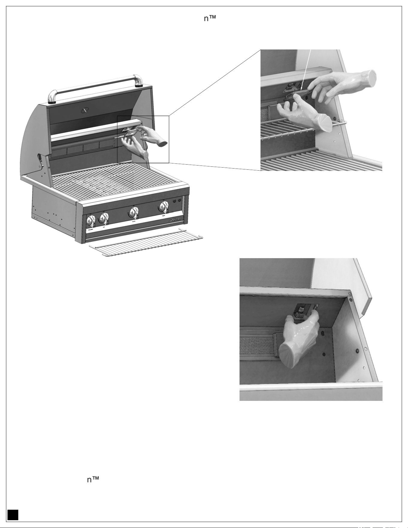
36
Should you need to replace the light bulb in you Artisan Grill, please refer to the following steps :
Reach inside the light fixture and remove the light bulb by
pulling it straight out of the socket.
INSTALLING A NEW LIGHT BULB:
NOTE: When replacing light bulbs, use a soft clean cloth
(cotton or paper towels) when handling lights.
Always keep halogen lights free of fingerprints and grease
when replacing. Because of the light bulb’s very high operat-
ing temperature, grease or fingerprints left on the light bulb
might reduce the bulb’s life.
Insert a new light bulb using a clean cloth and do not force the
light bulb in the socket. Very little effort is required for the
bulb to “SNAP” and lock into place.
Look at the bulb and verify that no fingerprints are left on it. Wipe off any fingerprints and or grease that
might have accidentally come in contact with the glass of the light bulb.
Replace the light cover by inserting it into the light fixture at a slight angle until it “SNAPS” into place.
Power up your Artisan Grill and verify the light bulb operation by turning on the light switch.
LIGHT COVER
REMOVE THE
LIGHT COVER
The light cover is supported by a spring
mechanism on the light fixture. Simply pry
open the light cover from the left or right
side by hand only.
DO NOT USE ANY TOOLS as you might
chip the tempered glass cover.
REMOVE THE
LIGHT BULB
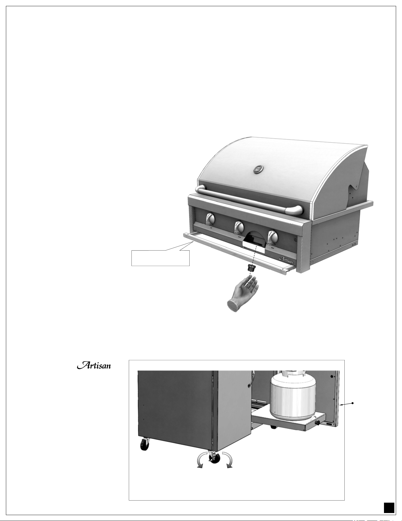
37
APPENDIX:
CART MOUNTED UNITS — CART SECUREMENT:
To prevent your
Cart and Barbeque from
rolling on a leveled or une-
ven floor, secure the cart’s
caster wheels located on
the front of the cart.
The caster wheels are ac-
cessible by opening the
doors and using the
wheel’s side lever to LOCK
or UNLOCK the backing
system of the wheels as
shown to the right.
OPEN
DOOR
LOCK
UNLOCK
CASTER
WHEEL
BATTERY REPLACEMENT:
All AAEP BBQ models have igniters powered by 9 Volt DC batteries. Batteries should be replaced when
poor spark ignition or very slow sparking performance is heard.
To insert or replace the battery which powers the igniters, please perform the following steps:
1. Slide the drip tray forward slightly, as shown below.
2. Unscrew the battery cap (rotate counterclockwise as viewed from below).
3. Either insert a new battery or replace the old battery with a new battery.
4. Replace the battery cap (rotate clockwise as viewed from below).
5. Slide the drip tray back in place.
NOTE:
All ARTP/ART models have 115 Volt igni-
tion system, thus no batteries are required or
replaced.
REMOVE CAP
(UNSCREW)
REPLACE CAP
(SCREW BACK)
DRIP TRAY

38
ADDITIONAL IMPORTANT CLEANING AND STORAGE CONSIDERATIONS:
In order to maintain your grill in clean working order, it will be necessary, under certain conditions, to take
additional precautions:
• If your gill is located in a coastal area, it will be exposed to salty air which is corrosive.
• If it is located close to a swimming pool or Jacuzzi with chlorinated water, then it will be exposed to
dilute hydrochloric acid which can be formed as a result of chlorine compounds used in the pool causing
chlorine to be combined with hydrogen and water in the atmosphere.
• Muriatic acid (another name for hydrochloric acid) is used to maintain the correct ph balance in the pool
water. Chlorine is an oxidizing agent, and as such can promote rapid corrosion or other oxidizing
processes which can damage various materials.
Type 304 stainless steel is highly resistant to corrosion but given enough exposure to such corrosive
conditions might succumb to some degree, such that pitting or rusting may occur.
Our barbecue materials have been tested in saline solutions with higher salinity than sea water, and they
have been tested in highly chlorinated solutions. They have also been tested by exposure to highly acidic
foods.
During and after these tests, we found these materials were able to withstand exposure over prolonged
periods of time. However, the above mentioned corrosive substances, along with neglect, can lead to a
situation whereby conditions might combine to cause some damage to occur.
Therefore, we suggest that you always keep your barbecue clean, dry and covered when not in use. This is
even more important when long term storage is intended; always store the grill clean, dry and covered with
an optional Artisan Barbecue Cover.
Do not allow any food particles or grease to be left inside your barbecue, as this will attract rodents which,
in addition to being undesirable from an hygienic standpoint, are likely to cause physical damage to your
barbecue. Rodents are known to chew on the insulation of wiring which will eventually cause permanent
damage to the wiring and possibly electrical components.
One final consideration for barbecues located either along the coast or in a desert community: Wind driven
sand is highly abrasive, therefore constant exposure will eventually pit and scratch almost anything; one
more reason to keep your barbecue covered when not in use.
By routinely caring for your barbecue as outlined in this manual, you can enjoy many years of service from
it and keep it looking the way it should.
In the event that any light rusting is found on the stainless steel, it will usually not be the stainless steel
which is corroding but iron particles which have somehow been deposited on the surface. For more
information on this subject, please request our “Rust removal bulletin”.
As a first course of action though, we recommend “Bar Keepers Friend”, available from many supermarkets
and hardware stores. This product, if used as directed, will usually solve the problem. Note though, when
using this product on textured surfaces such as your barbecue, always rub in the direction of the grain;
never across the grain, since doing so will damage the finish.
Refer also to pages 30-31 for additional Stainless Steel Care tips.

39
Artisan Limited Warranty
The warranties shown below commence on the date of the original purchase.
15 years - Stainless Steel Burners.
10 Years - All Stainless Steel Parts.
3 Years - Ceramic Briquette Trays (briquette excluded).
1 Year - Ignition Systems (Batteries excluded), Side Burners,
Rotisserie Motors and Thermometers.
TERMS APPLICABLE TO THE WARRANTY ABOVE:
Artisan Grill’s warranty applies only to products installed for normal residential use. The warranty
applies only to products installed in any one of the fifty states of the United States, the District of Columbia
or the ten provinces of Canada.
This warranty does not apply to rust, corrosion, oxidation or discoloration, unless the affected
component becomes inoperable, to correct any defect caused by negligence, accident or improper use,
maintenance, installation, service or repair. It does not cover labor or labor related charges.
Product must be installed and connected to a gas source in accordance with what is specified in the
installation instructions or in the Care and Use Manual, with no exceptions, and by a qualified professional
installer.
All replacement components, such as valves, etc, must be an Artisan product. Artisan’s warranty only
applies to the original purchaser and may not be transferred, and commences from the date of purchase,
and is valid only with proof of purchase.
Limitations & Exclusions: 1. Artisan’s warranty applies only to the original purchaser and may not be transferred. 2. Artisan’s warranty is in lieu of all other
warranties, expressed or implied and all other obligations or liabilities related to the sale or use of its grill products. 3. Artisan’s warranty shall not apply and
Artisan is not responsible for damage resulting from misuse, abuse, alteration of or tampering with the appliance, accident, hostile environment, flare-up fires,
improper installation, or installation not in accordance with the instructions contained in the User Manual, or the local codes. 4. Artisan shall not be liable for
incidental, consequential, special or contingent damages resulting from its breach of this written warranty or any implied warranty. 5. Some states do not allow
limitations on how long an implied warranty lasts, or the exclusions of or limitations on consequential damages. This warranty gives you specific legal rights and
you may have other rights, which vary from state to state. 6. No one has the authority to add to or vary Artisan’s warranty, or to create for Artisan any other
obligation or liability in connection with the sale or use of its products.
Artisan shall not be responsible for and shall not pay for the following: 1. Installation or start-up. 2. Service by an unauthorized service provider. 3. Damage
or repair due to service by an unauthorized service provider or use of unauthorized parts. 4. Improper installation. 5. Damage caused by accidents, abuse,
alteration, misuse, installation that is not in accordance with the instructions contained in the User Manual, or local codes. 6. Units installed in non-residential
applications such as retirement homes, restaurants, hotels, schools, etc. 7. To correct normal adjustments or settings due to improper installation, commissioning
or local gas supply properties. 8. Shipping and handling costs, export duties, or installation cost. 9. The cost of service calls to diagnose trouble; or removal or re-
installation cost.
SERVICE & REPLACEMENT PARTS:
For quicker and easier results, visit our website at: http://www.artisangrills.com or, call our toll free
number at: (866)-203-5607 to report service problems and / or to obtain replacement parts for your
Artisan Grill. Replacement parts are shipped F.O.B. City of industry, California 91745.
Before calling for service, please make sure you have the following information:
• Model number and Serial number, Date of purchase and Proof of purchase.
The warranty specifically excludes liability for indirect, incidental or consequential damages.
This product is designed for residential use only.
FOR WARRANTY CLAIMS PLEASE CALL: (866) 203-5607

40