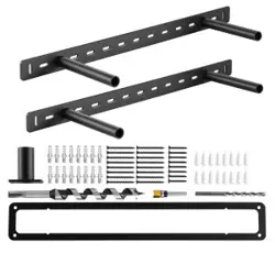
LED Floating Shelf Bracket
User Manual
• 12V DC ONLY: Never connect this product directly to high-voltage AC power
(110V/120V). You must use a 12V DC Constant Voltage LED Driver.
• CERTIFICATION: To prevent fire or electric shock, ensure your external power supply
(Driver/Adapter) is NRTL certified (e.g., UL, ETL) and rated for use in your region.
• WATTAGE CHECK: The rated wattage of your power supply must be greater than the
total wattage of all connected shelves combined. (See "Power Selection" for details).
• INSTALLATION: We strongly recommend having this product installed by a certified
electrician, especially if wiring inside walls. The manufacturer assumes no liability for
improper installation or electrical work.
IMPORTANT SAFETY INSTRUCTIONS
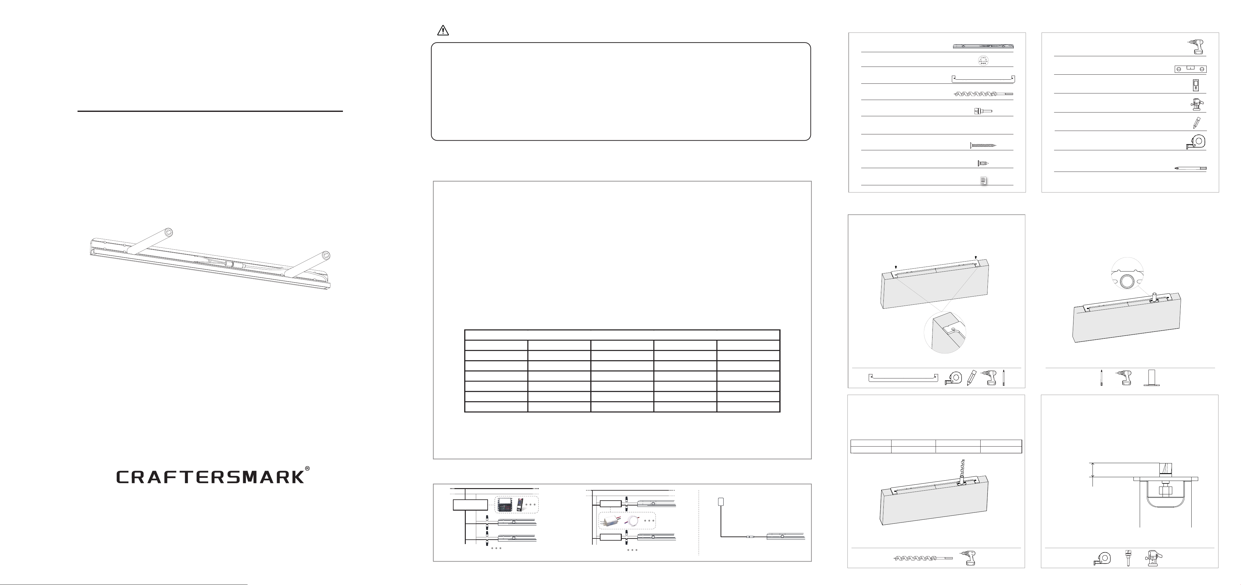
Power Selection
(NOTE: LED Driver / Power Adapter is NOT included. You must purchase one
separately based on your setup.)
Option 2: External Power Adapter (Plug-in)
Select a 12V DC Adapter appropriate for the shelf's wattage. Use one adapter
per shelf. Connect using the standard DC 3.5mm plug.
Option 1: Hardwired Driver
▪ Single Shelf: Choose a 12V DC driver that matches the
wattage rating in the chart below.
▪ Multiple Shelves: If connecting multiple shelves to one
driver, the driver's wattage must handle the TOTAL
power of all shelves.
Calculation Example (How to choose a driver):
lf you are installing two 40-inch shelves:
1.Check chart: One 40" shelf = 10 Watts
2.Total Power: 10W + 10W = 20 Watts.
Shelf Length Voltage Rated Power Color Temp Lumens
18 inch DC 12V 4.5 W 2700K 360LM
22 inch DC 12V 5.5 W 2700K 440LM
28 inch DC 12V 7.0 W 2700K 560LM
34 inch DC 12V 8.5 W 2700K 680LM
40 inch DC 12V 10.0 W 2700K 800LM
46 inch DC 12V 11.5 W 2700K 920LM
Specifications Chart
3.Result: You need a 12V DC Driver rated for at least 20W (we recommend
24W or higher).
Wiring Diagram
AC(L)
AC(N)
12V Driver
AC(L)
AC(N)
12V Driver
12V Driver
12V DC Adapter(Not included)
3.5mm Plug
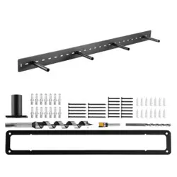
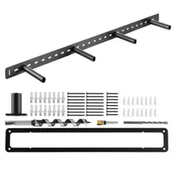
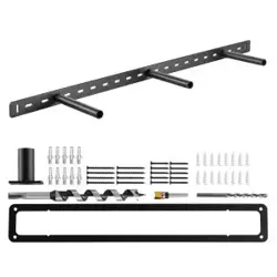
Packing list
Prepare Your Shelf (Drilling & Routing)
Tools You’ll Need
1.Attach the Routing Jig
Align the Routing Jig with the back edge of your
wood shelf. Center it perfectly. Secure it using the
provided short screws (KA4.0*30mm).
2.Attach the Drilling Jig
Insert the Drilling Jig into the slot of the Routing
Jig. Align the notch/tab to lock it in place. Secure
with short screws (KA4.0*30mm).
Tools You’ll Need
Tools You’ll Need Tools You’ll Need
3.Drill the Rod Holes
Using a power drill and the provided Auger Bit
(16x300mm), drill holes into the wood for the
bracket rods. Repeat Steps 1-3 for all rod holes
before proceeding.
Bracket Rod 4 inch 6 inch 8 inch
Hole 5 inch 7 inch 9 inch
21.9mm
(approx. 7/8")
4. Install Router Bit
Remove the Drilling Jig. Install the provided
Router Bit (3/4" Dia x 5/8" Deep) into your router.
Adjust the bit height to exactly 21.9mm (approx.
7/8").
Cross Screwdriver
Required Tools (Not Included)
Measuring Tape
Drill
Pencil
Stud Finder
Level
Router
LED Shelf Bracket
Auger Bit
Routing Jig
Long Screws
Router Bit
Short Screws
Installation Guide
Drilling Jig
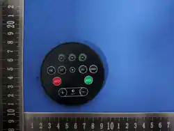
Remote Control
Tools You’ll Need Tools You’ll Need
Finished
6.Test-Fit the Bracket
Remove all jigs. Insert the bracket into the routed
recess and holes. It should sit flush (flat) against
the wood surface.
5.Route the Recess
Use the router to carve out the recess for the
bracket's backplate inside the Routing Jig area.
Make several shallow passes for a clean and safe
cut.
Recess depth: 15.9mm (5/8")
Tools You’ll Need
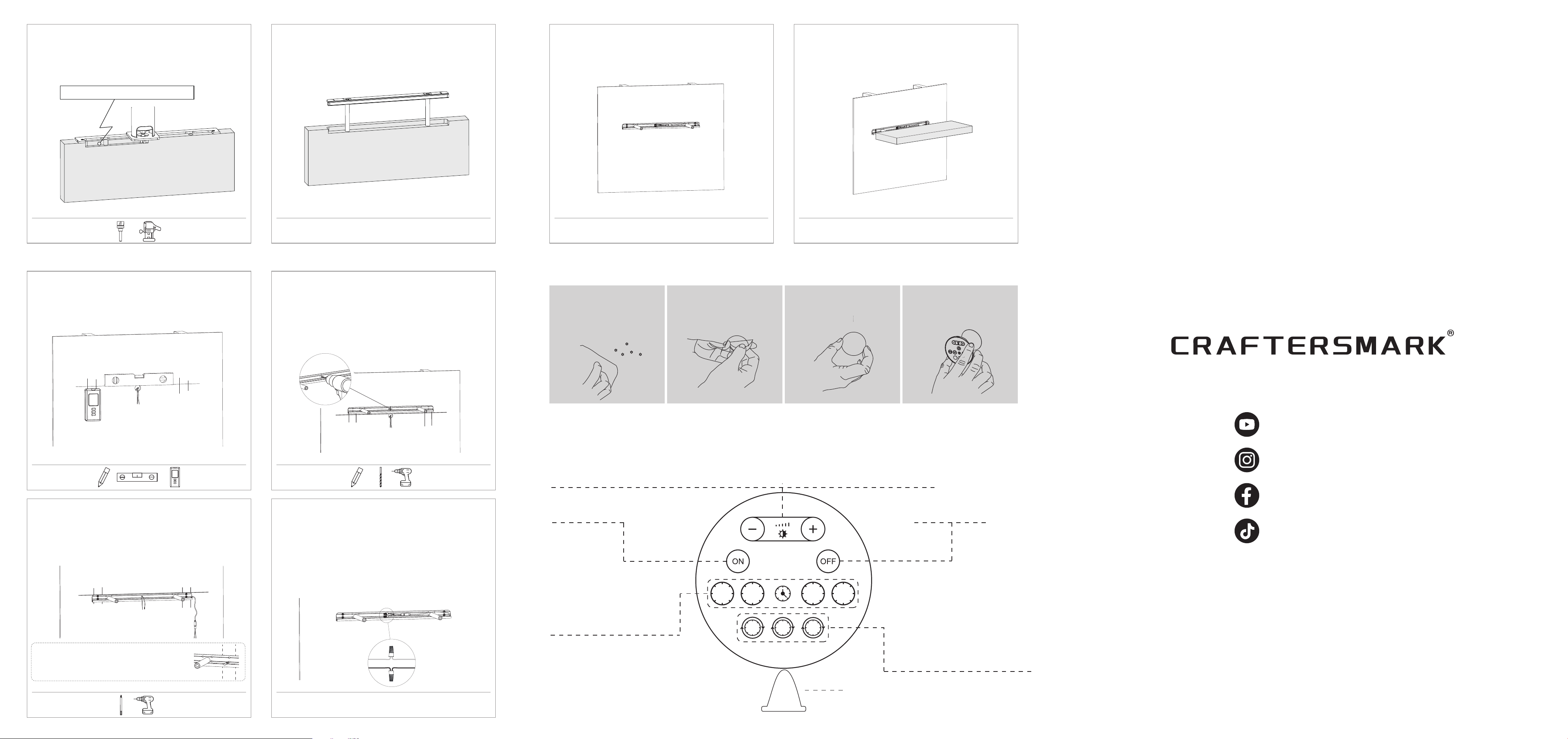
Mounting the Bracket to the Wall
3.Mount the Bracket
Feed the power wires through the newly drilled
hole. Align the bracket with your wall studs and
reference line. Secure it to the studs using the
Long Screws (KA M4*50).
2.Drill Wiring Hole in Bracket
Mark the wiring connection position on the brack-
et. Use the provided Metal Drill Bit to drill a hole
through the bracket at the marked location to
allow wires to pass through.
Note:
Skip this step if using the Plug-in Power Adapter.
Pro Tip:
If the pre-drilled slots on the bracket do not align
with your wall studs, use the provided Metal Drill
Bit to drill new mounting holes in the bracket
backplate that align with your studs.
Tools You’ll Need
1. Mark Wall Location
Determine your desired shelf height. Use a Level
to mark a horizontal reference line. Use a Stud
Finder to locate and mark your wall studs.
Tools You’ll Need
Tools You’ll Need
5.Test Light
Turn on the power. Use the remote control to turn
the light on and off, verifying that the system
works properly.
4.Electrical Connection
Connect your power supply wires to the shelf
wires using the wire connectors.
WARNING: Check Polarity! Ensure you connect the
Positive (+) wire from the driver to the Positive
(+) shelf wire, and Negative (-) to Negative (-).
Note:
If using the Plug-in Power Adapter, skip this step.
Simply plug the adapter into the shelf in Step 5.
Tools You’ll Need
6.Final Installation
Once confirmed, slide the wood shelf onto the
bracket rods until it sits flush against the wall.
Ensure the shelf is stable and perfectly level.
Tools You’ll Need
Finished
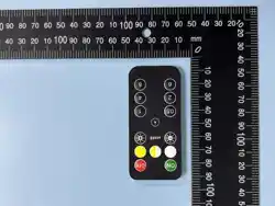
Remote Control Installation (Note: Mount on smooth, flat surfaces only)
1.Determine the loca-
tion. Clean the surface
to ensure it is free of
dirt and dust.
2.Peel off the protec-
tive film from the metal
plate.
3.Stick the metal plate
to your desired loca-
tion.
4.Attach the remote
control to the metal
plate, it holds magneti-
cally.
Using the Remote Control
30Min
1H
3H
2H
1H 2H 3H
Brightness Adjustment
Short press "+": Increase brightness in steps (10 levels).
Long press "+": Stepless dimming - The brightness smoothly increases until you release.
Short press "-": Decrease brightness in steps (10 levels).
Long press "-": Stepless dimming - The brightness smoothly decreases until you release.
Power Buttons
Turn the light on.
Power Buttons
Turn the light off.
One-Time Timer
Press 30Min, 1H, 2H, or 3H.
The light will automatically
turn off after the selected
time elapses. The indicator
light flashes once to confirm.
Transparent film: Remove before use.
Daily Memory Timer
Options with circle arrows (1H,
2H, 3H). Once selected, the light
stays on for the set duration,
turns off, and automatically turns
on at the exact same time every
day. The light flashes once to
confirm your selection.
Need More Installation Help?
Email us at
@Craftersmarkofficial
@craftersmark
@Craftersmarkofficial
@Craftersmark

FCC Warning
This device complies with Part 15 of the FCC Rules. Operation is subject to the following two conditions:
(1) This device may not cause harmful interference, and (2) this device must accept any interference received, including interference that may cause undesired operation.
NOTE 1: This equipment has been tested and found to comply with the limits for a Class B digital device, pursuant to part 15 of the FCC Rules. These limits are designed to provide reasonable protection
against harmful interference in a residential installation. This equipment generates, uses and can radiate radio frequency energy and, if not installed and used in accordance with the instructions, may cause
harmful interference to radio communications. However, there is no guarantee that interference will not occur in a particular installation. If this equipment does cause harmful interference to radio or
television reception, which can be determined by turning the equipment off and on, the user is encouraged to try to correct the interference by one or more of the following measures:
- Reorient or relocate the receiving antenna.
- Increase the separation between the equipment and receiver.
-Connect the equipment into an outlet on a circuit different from that to which the receiver is connected.
-Consult the dealer or an experienced radio/TV technician for help.
NOTE 2: Any changes or modifications to this unit not expressly approved by the party responsible for compliance could void the user's authority to operate the equipment.
The device has been evaluated to meet general RF exposure requirement. The device can be used in portable exposure condition without restriction.