5240 Willis Rd.
Theodore, AL 36582 USA
Toll Free: 1 (855) 223-2665
Tel: 1 (805) 933-9970
coolboss.com
Cool Boss™ HVLS Industrial Ceiling Fan
Installation and Operation Manual
Manual 5900279 — Revision A2 — May 2023
Models:
CB-11HVLS
CB-16HVLS
CB-20HVLS
CB-24HVLS
Designed and engineered by BendPak Inc. in Southern California, USA. Made in China.
⚠ DANGER
Read the entire contents of this manual before using this product. Failure to follow the
instructions and safety precautions in this manual can result in severe injury or death. Make sure all
other operators also read this manual. Keep the manual near the product for future reference.
By
proceeding with setup and operation, you agree that you fully understand the contents of
this manual and assume full responsibility for product use.
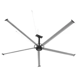
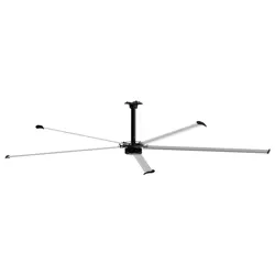
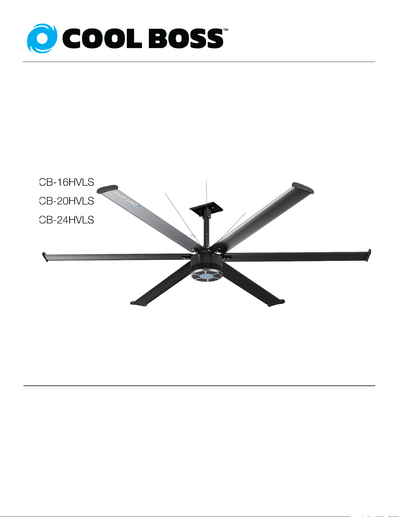
CB-16HVLS Pictured above.
Actual product color may vary.

Manual. Cool Boss™ HVLS Industrial Ceiling Fan Series, Installation and Operation Manual, P/N 5900279,
Manual Revision A2, May 2023.
Copyright. Copyright © 2023 by BendPak Inc. All rights reserved. No part of this manual can be reproduced,
adapted, translated, or transmitted by any means, electronic or mechanical, for any purpose or in any form,
without prior written permission of BendPak Inc.
Trademarks. Cool Boss, the Cool Boss logo, and BendPak are trademarks of BendPak Inc. All other company,
product, and service names are used for identification only. All trademarks and registered trademarks mentioned
in this manual are the property of their respective owners.
Limitations. Every effort has been made to ensure complete and accurate instructions are included in this
manual. However, product updates, revisions, and/or changes may have occurred since this manual was
published. BendPak reserves the right to change any information in this manual without incurring any obligation for
equipment previously or subsequently sold. BendPak is not responsible for typographical errors in this manual.
Warranty. The Cool Boss warranty is more than a commitment to you: it is also a commitment to the value of
your new product. Visit coolboss.com/warranty for complete warranty information.
Safety. Your new product was designed and manufactured with safety in mind. Your safety also depends on
proper training and thoughtful operation. Do not set up, operate, maintain, or repair your Cool Boss without
reading and understanding this manual and the labels on the unit.
Owner Responsibility. In order to ensure operator safety and maintain your product properly, it is the
responsibility of the product owner to read and follow these instructions:
• Follow all setup, operation, and maintenance instructions.
• Verify product setup and use conforms to all applicable local, state, and federal codes, rules, and regulations,
such as state and federal OSHA regulations and electrical codes.
• Read and follow all safety instructions. Keep them readily available for operators.
• Make sure all operators are properly trained, know how to safely operate the unit, and are properly supervised.
• Do not operate the product until you are certain all components are in place and operating correctly.
• Carefully inspect the product on a regular basis and perform all maintenance as specified.
• Service and maintain the unit only with approved replacement parts.
• Keep all instructions permanently with the product and make sure all labels are clean and visible. BendPak
makes no promises, guarantees or assurances that our products meet any state, county, federal or
international mandated permit, license, code, standard, certification, or any other mandate other than what is
listed or shown on Cool Boss, BendPak website(s), or any BendPak, Cool Boss or Ranger online or published
catalog. Buyer assumes full responsibility for any state, county, federal or international mandated permit,
license, code, standard, certification, or any other mandate required related to the installation and/or operation
of any BendPak, Cool Boss or Ranger product. BENDPAK will not be responsible for any charges, fines, liens,
or other levies imposed on the Buyer related to any special or regional fire, structural, seismic or any other
building code and/or codes such as the Uniform Building Code (UBC), International Building Code (IBC), or
any other state, county, federal or international mandated permit, license, code, standard, certification, or
other mandate, law, rule, regulation or directive by any other agency, government, administrations, or
corporations whether state, county, federal, or international mandated.
Only use this HVLS Fan if it can be used safely
Unit Information. Enter the Model Number,
Serial Number, and Date of Manufacture from the
label on your unit. This information is required for
part or warranty issues.
Model:
Serial:
Date of Manufacture:

Cool Boss Industrial HVLS Fan 3 P/N 5900279 — May 2023 — Rev. A2
Table of Contents
Introduction 3 Operation 32
Shipping Information 4 Maintenance 35
Safety Considerations 4 Troubleshooting 37
Frequently Asked Questions 6 Wiring Diagram 39
Specifications 7 Parts Diagram 45
Components 9 Labels 47
Installation 11 Maintenance Log 49
Introduction
The Cool Boss High Volume Low Speed (HVLS) Industrial Ceiling Fan keeps your shop or workplace
cool and comfortable on even the hottest summer days. The Cool Boss HVLS Fans are an economical
year-round ventilation solution. Cool Boss Models CB-20HVLS and CB-24HVLS described here also
feature a negative air ionizer. All Cool Boss HVLS Fans utilize highly reliable permanent magnet
(synchronous) motors to drive the Fan Blades directly without reduction gearing. The Fan controller
utilizes a Variable Frequency Drive (VFD) to control Fan speed and torque. The Fan Blades are
constructed of high strength, fatigue resistant aluminum alloy, powder coated to ease cleaning and
ensure long life. All models require 220 VAC, 50/60 Hz. electrical power. This manual applies to all four
Cool Boss HVLS Fans. There are minor mechanical and electrical differences between the Fan models.
These differences will be clearly identified in the manual and labelled by model number.
CB-11HVLS has a nominal diameter of 11.5 ft. / 3.5 m.
CB-16HVLS has a nominal diameter of 16.5 ft. / 5 m.
CB-20HVLS has a nominal diameter of 20 ft. / 6 m includes an ion generator.
CB-24HVLS has a nominal diameter of 24 ft. / 7.3 m includes an ion generator.
This manual is mandatory reading for all users of the Cool Boss HVLS Fans, including
anyone who installs, operates, maintains, or repairs them. Always keep this manual on or near the
equipment.
⚠ DANGER Be very careful when setting up, operating, maintaining, or repairing this equipment;
failure to do so correctly could result in property damage, product damage, injury,
or (in rare cases) death. Make sure only authorized personnel operate this
equipment. All repairs must be performed by an authorized technician. Do not
make modifications to the unit; this voids the warranty and increases the chances
of injury or property damage. Make sure to read and follow the instructions on the
labels on the unit.

Cool Boss Industrial HVLS Fan
4
P/N 5900279 — May 2023 — Rev. A2
Keep this manual on or near the equipment so that anyone who uses or services
the unit can read it. Assistance with your Cool Boss is available from your dealer,
by calling Cool Boss at (855) 2BE-COOL, or by emailing
[email protected]. You may also contact Cool Boss for parts
replacement (please have the serial number and model number of your unit
available).
Scan this QR Code for up-to-date information and videos on Cool Boss Fans.
Shipping Information
Your equipment was carefully checked before shipping. Nevertheless, you should thoroughly inspect
the shipment before you sign to acknowledge that you received it.
When you sign the bill of lading, it tells the carrier the items on the invoice were received in good
condition. Do not sign the bill of lading until after you have inspected the shipment. If any of the
items listed on the bill of lading are missing or are damaged, do not accept the shipment until the
carrier makes a notation on the bill of lading that lists the missing and/or damaged goods.
If you discover missing or damaged goods after you receive the shipment and have signed the bill of
lading, notify the carrier at once and request the carrier to make an inspection. If the carrier will not
make an inspection, prepare a signed statement to the effect that you have notified the carrier (on a
specific date) and that the carrier has failed to comply with your request.
It is difficult to collect for loss or damage after you have given the carrier a signed bill of lading. If this
happens to you, file a claim with the carrier promptly. Support your claim with copies of the bill of
lading, freight bill, invoice, and photographs, if available. Our willingness to assist in helping you
process your claim does not make us responsible for collection of claims or replacement of lost or
damaged materials.
Safety Considerations
Read this manual carefully before using your new product. Do not set up or operate
the product until you are familiar with all operating instructions and warnings. Do not allow anyone else
to operate the product until they are also familiar with all operating instructions and warnings.
⚠ WARNING California Proposition 65. This product can expose you to chemicals including
styrene and vinyl chloride which are on a list of over nine hundred chemicals
identified by the State of California to cause birth defects or reproductive harm.
ALWAYS use this product in accordance with BendPak and Cool Boss’
instructions. For more information go to www.P65Warnings.ca.gov.
Safety Information
• The product is an air-moving device. Use it only for its intended purpose.
• The product should only be operated by authorized personnel. Children should not be allowed
operate the Cool Boss HVLS Fan. Make sure all operators read and understand the Warning labels
and this Installation and Operation Manual. Keep the manual near the Fan at all times.
• Never operate any Cool Boss equipment with damaged wiring.
• When the product is in use, keep all body parts away from it. No personnel should be closer than
ten-feet (3-meters) from this device while it is operating.
• Outdoor installation is prohibited. Only use this product indoors in a well-ventilated area.
Ensure a window or door is open to allow adequate air flow.
• Always use appropriate tools and lifting equipment.
Cool Boss Industrial HVLS Fan
5
P/N 5900279 — May 2023 — Rev. A2
• Save these instructions! Always stay clear of moving parts.
• Do not make any modifications to the product. Modifications void the warranty and increases the
chances of severe injury or property damage.
• Extension cord use is prohibited.
• Do not spray any part of the Fan or its controller with water. Moisture can harm the motor and
other parts of the electrical system.
• Only connect the Motor Controller to a GFCI protected circuit.
• Make a visual inspection of the product before using it. Check for damaged or missing parts. Do
not use the product if you find problems with the unit. Instead, remove it from service,
then contact your dealer, call Cool Boss at (805) 933-9970, or email Cool Boss at
• Do not operate the Cool Boss if the Fan has cracked, damaged or worn components.
• Do not operate the Cool Boss within 35-feet (10.6 m) of an open flame or spark.
• Do not operate the Cool Boss in an environment with flammable or corrosive gasses.
• Do not operate the Cool Boss in an environment where powdered metal, oil, water, or other
foreign matter can enter the Motor or its Controller.
• Always remove and lockout electrical power before performing inspection, maintenance, or
repairs on this Fan.
• BendPak recommends making a thorough inspection of the product at least once a year. Replace
any damaged or severely worn parts, decals, or warning labels.
• Even if the main Fan Motor is stopped and the switch is in the off position,
hazardous voltage may be present on the circuit terminals. Only licensed Electricians
should be allowed to open and service the Cool Boss HVLS Fan Control Panel or Fan Motor.
Symbols
Following are the symbols used in this manual:
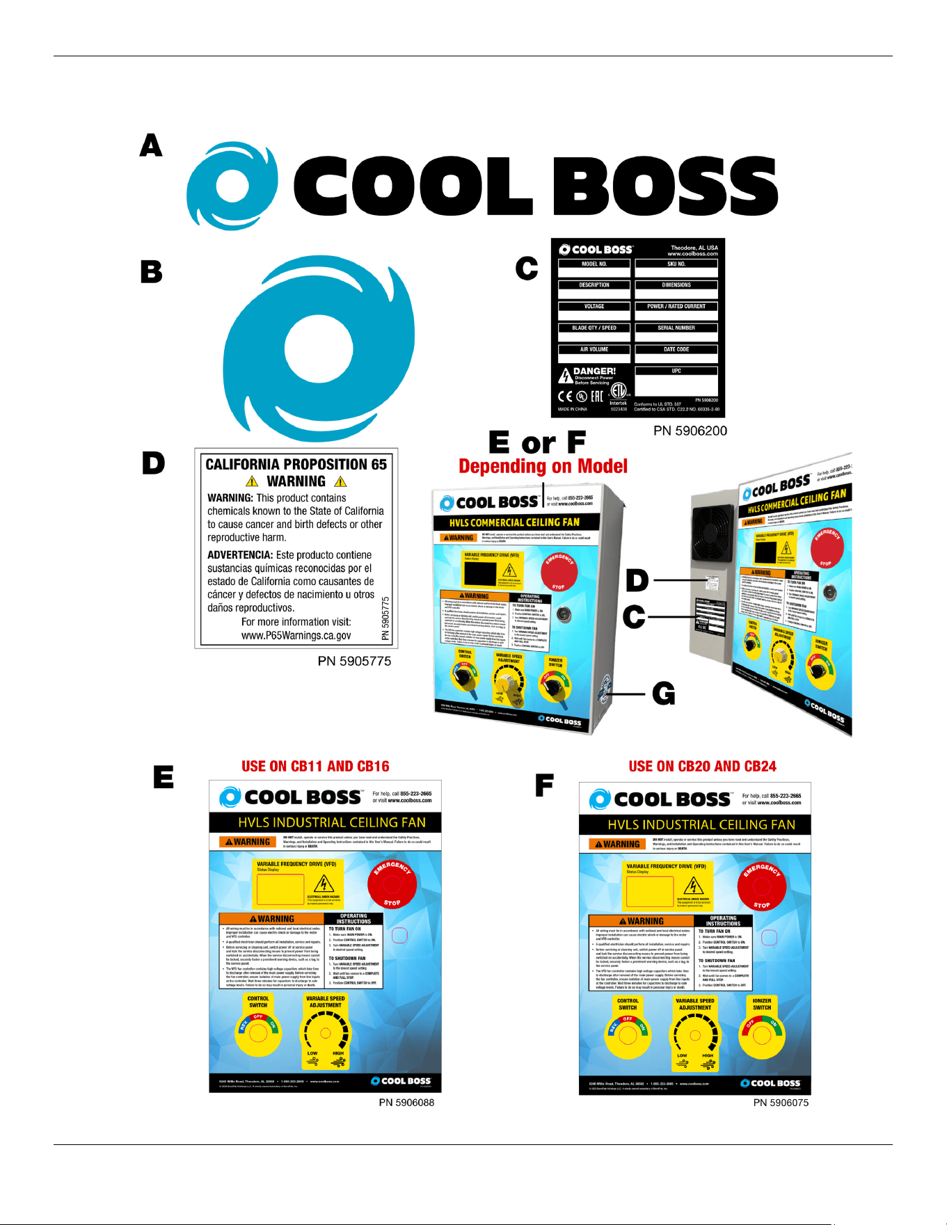
⚠ DANGER Calls attention to an immediate hazard that will result in death or severe injury.
⚠ WARNING Calls attention to a hazard or unsafe practice that could result in death or severe
personal injury.
⚠ CAUTION Calls attention to a hazard or unsafe practice that could result in minor personal
injury, product, or property damage.
Tip Calls attention to information that can help you use your product better.
Liability Information
BendPak Inc. assumes no liability for damages resulting from:
• Use of the equipment for purposes other than those described in this manual.
• Modifications to the equipment without prior, written permission from BendPak Inc.
• Injury or death caused by modifying, disabling, overriding, or removing safety features.
• Damage to the equipment from external influences.
• Incorrect operation of the equipment.
Cool Boss Industrial HVLS Fan 6 P/N 5900279 — May 2023 — Rev. A2
Frequently Asked Questions
Question: What is an HVLS Fan?
Answer: A High Volume, Low Speed Fan. This type of Fan relies on its size to move large quantities
of air while the actual rotation speed remains low. The Fan directs air toward the floor where it is
dispersed, creating a cool breeze over the area. This effect can lower the perceived air temperature by
as much as ≈10°F / 6°C.
Q: How much air does the Cool Boss HVLS Fan
move?
A: Each Fan can move approximately:
Q: What is the recommended spacing for multiple
Cool Boss HVLS Fans?
A: The spacing varies with the Fan size. Refer to
figure 5 in the Find a Location section.
Q: How close can I mount the Cool Boss Fan to Stock Racks and or walkways and mezzanines?
A: Air flow from the Fan will be deflected by solid objects. This disruption may cause turbulence which
can affect the Fan’s performance. Keep the Fan Blade ends at least two Fan diameters away from
walls and see Find a Location for distance to obstructions.
Q: What are the requirements for Fan distance to fire sprinklers?
A: Consult local Fire regulations regarding the placement of the Fan around fire protection equipment.
Q: Is it difficult to control the Cool Boss?
A: Not at all. There are three controls. A Control Switch (Rev. – Off – On), a Variable Speed
Adjustment, and an Ionizer Switch (On-Off). The Variable Frequency Drive does all the hard work
for you.
Q: How much maintenance does the HVLS Fan require?
A: Very little. Maintenance consists of annual inspections for mechanical wear on the Fan Blades, and
the mounting hardware. Verify all mounting hardware is secured and inspect for wear on the Guy Wires
and attachments. Refer to the Maintenance Section for more specific information.
Q: Is the HVLS Fan suitable for wet dirty environments?
A: No! Installation is not permitted in wet or dirty environments.
Q: Can I swap to larger or smaller Fan Blades?
A: No! Fan Blades are specifically designed for this Motor and Controller. Replacing components with
larger or smaller components will cause an imbalance and damage or destroy the Fan. This could also
lead to injury of nearby personnel.
Q: Can I swap to a different Motor Controller?
A: No! The Synchronous Motor Controller is specifically programmed for the specific motor and blade
size to develop the correct torque and speed. Do not substitute components!
Q: What is an Air Ionizer?
A: The Cool Boss Ion Generator utilizes high voltage to electrically charge the air moving through the
Fan. This electrical charge generates negative ions (Anions) in the air. Anions are highly effective at
removing particulates from the air.
Model Air Volume
CB-11HVLS
148,321 cfm / 4,200 cmm
CB-16HVLS
360,210 cfm / 10,200 cmm
CB-20HVLS
448,496 cfm / 12,700 cmm
CB-24HVLS
524,422 cfm / 14,850 cmm
Cool Boss Industrial HVLS Fan
7
P/N 5900279 — May 2023 — Rev. A2
Specifications
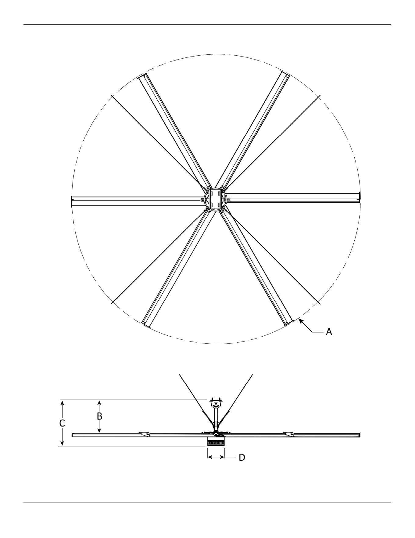
Top View
Side View
Cool Boss Industrial HVLS Fan 8 P/N 5900279 — May 2023 — Rev. A2
All specifications subject to change without notice.
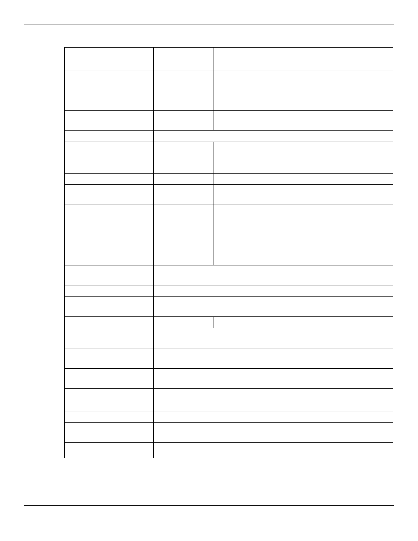
Model CB-11HVLS CB-16HVLS CB-20HVLS CB-24HVLS
A – Fan Diameter
11.5 ft. / 3.5 m 16.5 ft. / 5 m 20 ft. / 6.1 m 24 ft. / 7.3 m
B – Mount to Blades
42.5 in. /
1,080 mm
41.3 in. /
1,049 mm
43.3 in. /
1,100 mm
43.3 in. /
1,100 mm
C – Mount to Motor
overall length
49.2 in. /
1,250mm
51.5 in. /
1,310 mm
54.3 in. /
1,379 mm
54.3 in. /
1,379 mm
D – Motor Diameter
13.4 in. /
340 mm
13.4 in. /
340 mm
17.3 in. /
439 mm
17.3 in. /
439 mm
Down Rod Length*
40 in. / 1016 mm
Optimum Ceiling
Height
17 ft. / 5.2 m 25 ft. / 7.5 m 30 ft. / 9.1 m 36 ft. / 10.9 m
Fan Speed - Variable
90 RPM Max. 78 RPM Max. 60 RPM Max. 55 RPM Max.
Number of Blades
6 6 5 5
Air Volume
148,321 cfm /
4,200 cmm
360,210 cfm /
10,200 cmm
448,496 cfm /
12,700 cmm
524,422 cfm /
14,850 cmm
Fan Hanging Weight
152 lbs. /
69 kg
209.5 lbs. /
95 kg
282 lbs. /
128 kg
295.5 lb. /
134 kg
Voltage/Current
208-230 VAC,
5 Amps
208-230 VAC,
5 Amps
208-230 VAC,
7 Amps
208-230 VAC,
7 Amps
Frequency/Phase
50/60 Hz.,
Single Phase
50/60 Hz.,
Single Phase
50/60 Hz.,
Single Phase
50/60 Hz.,
Single Phase
Motor
High Efficiency Variable Speed Direct Drive Permanent Magnet
Synchronous Motor (PMSM)
Motor Control
Compact Variable Frequency Drive (VFD)
Control Cable
Length
≈80 ft. / 25 m
Ion Generator
No No Yes Yes
Overcurrent
Protection
Standard
Over Temperature
Protection
Standard
Motor Overload
Protection
Standard
Sound Level
≤40 db
Certifications
UL Standard 507, UL 1004-1, CSA C22.2
Intertek ETL Listed
Yes
Operating
Temperature
-13° to +140° F / -10.5° to +60° C
Operating Humidity
<95% Non-Condensing
*Custom Down Rod lengths available.
Cool Boss Industrial HVLS Fan
9
P/N 5900279 — May 2023 — Rev. A2
Components
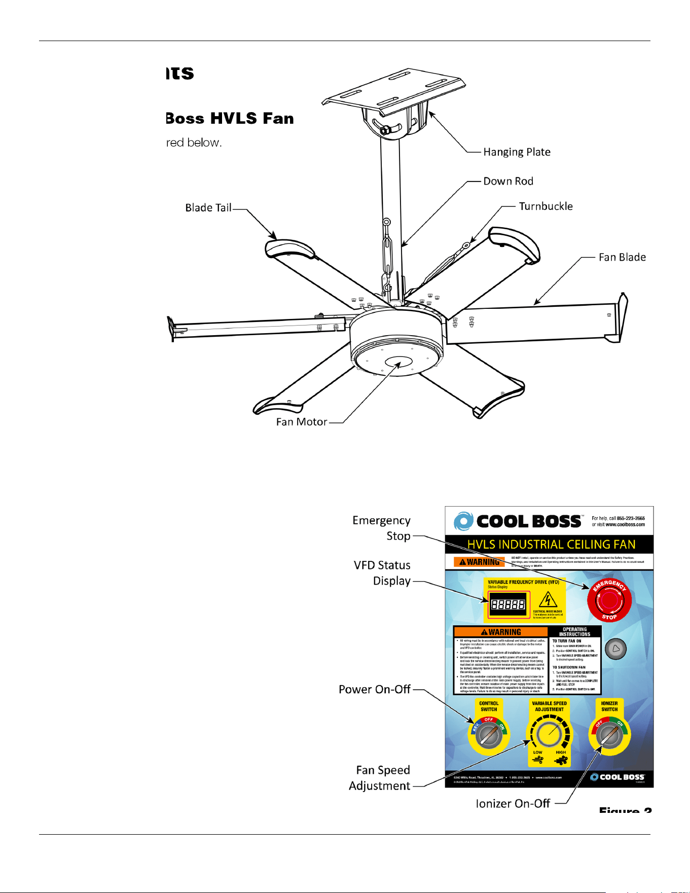
The Cool Boss HVLS Fan
CB-11 pictured below.
The Cool Boss Fan Control Panel
Control Functions
The Control Panel houses the Variable
Frequency Drive and the user controls.
Control Switch
Right - ON for CW rotation
Center - OFF
Left - REV. - for CCW rotation
Fan Speed Adjustment – Adjusts the
Fan rotation speed.
VFD Status Display – Displays
Variable Frequency Drive function and
error codes.
Emergency-Stop – Immediately
removes power from the Fan and
Control. Press to activate, rotate to
release.
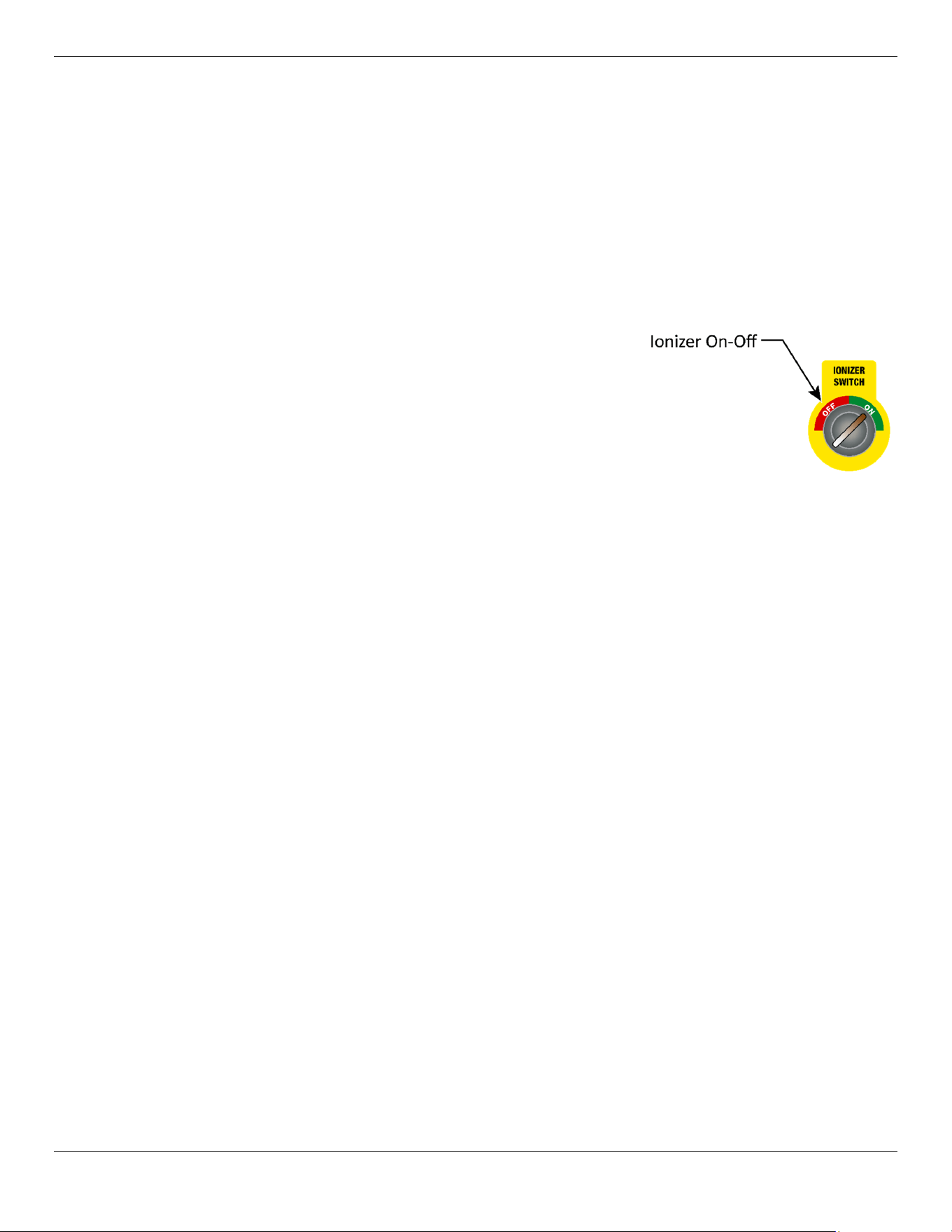
Ionizer On-Off – Rotate right to apply
power to the Ionizer.
*Available on CB-20HVLS and
CB-24HVLS only.
Figure 1
Figure 2

Cool Boss Industrial HVLS Fan 10 P/N 5900279 — May 2023 — Rev. A2
Installation Checklist
There are eight basic steps in the Cool Boss HVLS Fan set up.
1. Find a location.
2. Unbox the Fan.
3. Mounting the Fan Brackets
4. Attach the Blade Connector (CB-11 Only)
5. Install the Fan on its Down Rod
6. Installing the Fan on its Hanging Plate
7. Installing the Guy Wires and Leveling the Fan
8. Installing the Fan Blades CB-11
9. Installing the Fan Blades CB-16, CB-20 and CB-24HVLS
10. Installing the Arc Plate Sections CB-16, CB-20 and CB-24HVLS
11. Installing the Cover
12. Installing the Control and Connect to Power (Electrician required.)
13. Operational Test for function.
14. Leave the Manual with the Fan Owner/Operator.

Cool Boss Industrial HVLS Fan
11
P/N 5900279 — May 2023 — Rev. A2
Installation
The installation process includes multiple steps. Perform them in the order listed.
⚠
WARNING
Use only the factory-supplied parts shipped with your Lift. If you use attachments,
accessories, or configuration modifying components that are in the path and/or
affect the operation of the equipment, affect the equipment’s electrical listing, or
affect the intended accommodation, and if they are not certified for use with this
Fan, then you void the warranty of the Fan as well as compromising the safety of
everyone who sets up or uses the Fan. If you are missing parts, visit
CoolBoss.com/Support, email [email protected] or contact Cool
Boss Technical Support at (805) 933-9970 (please have the serial number and
model number of your unit available).
⚠ WARNING The Cool Boss HVLS Fan is heavy and awkward to work with. Installation should be
accomplished by competent personnel ensuring the Fan is properly rigged and
balanced for lifting. Installation personnel should have knowledge, training, and
experience in lifting, rigging, and securing heavy objects overhead.
⚠ WARNING Only properly trained and equipped personnel should be working with the Fan on
elevated work platforms or aerial lifts.
⚠ WARNING Block off the area under the installation site. Do not allow personnel to walk near or
under the area while work aloft is underway.
⚠ WARNING You must wear the proper protective equipment at all times during setup and
assembly of the HVLS Fan: eye protection, head protection, leather gloves, steel-
toed boots, back belts, including a proper harness and tie-in equipment for fall
protection while working overhead.
Tools required for Assembly:
Drill or Hammer Drill Metric Socket and Ratchet Set
Tape measure Level
Phillips and Flat Head Screwdrivers Wire Rope Cutters
Metric Open/Closed End Wrench Set Personnel Lift or equal
Metric Allen Wrench Set
Lifting and rigging equipment
Hammer Pry Bar
You will need an assistant. This is not a one-man installation!
Find a location for the Cool Boss HVLS Fan
Find a suitable location for the Cool Boss. Consider the following when selecting a location for the Cool
Boss HVLS Fan.
The Cool Boss should be mounted indoors near an appropriate power source
Cool Boss Industrial HVLS Fan
12
P/N 5900279 — May 2023 — Rev. A2
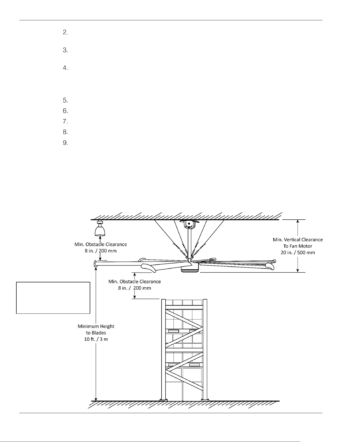
In a ventilated area with vertical space to allow the lowest part of the Fan to remain more than
ten feet (3 m) off the floor.
≈80-Feet (25 m) of Control Cable is provided with the HVLS fan. The Fan Control must be
attached to a wall or column close enough to allow connection using this cable.
Before installing your Fan, review all fire and building codes applying to fire suppressing
sprinkler systems. The Fan should not be allowed to interfere with installed fire sprinkler
systems. It is the owner’s responsibility to verify compliance with all national, state, and local
fire and building codes.
Fan position shall be roughly centered between any four adjacent fire sprinklers.
Operating temperature must remain between +5° to +131° F / -15° to +55° C.
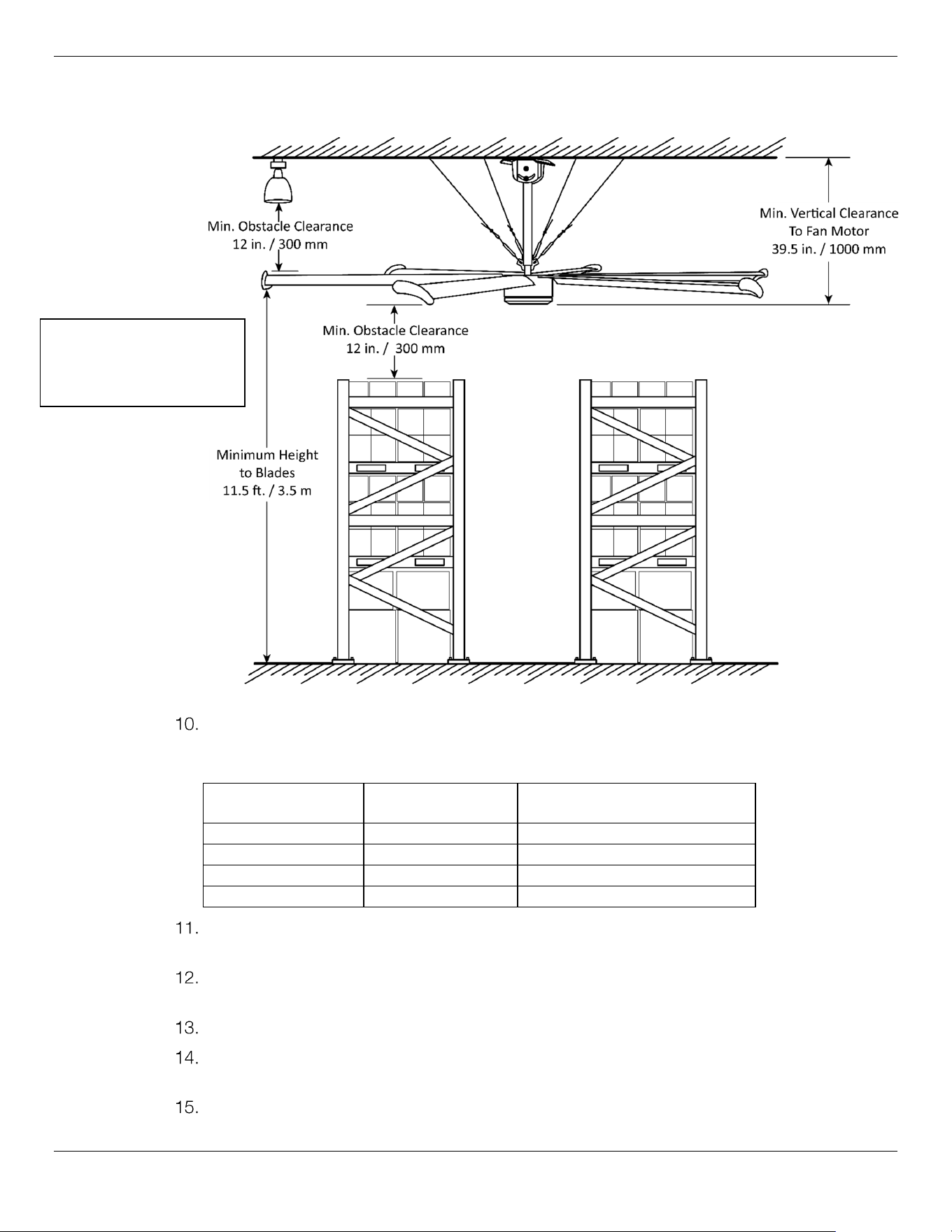
Vertical clearances for the CB-11 and CB-16, refer to figure 3.
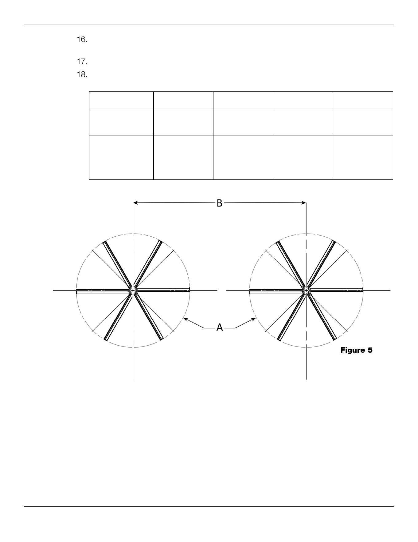
Vertical clearances for the CB-20 and CB-24 refer to figure 4.
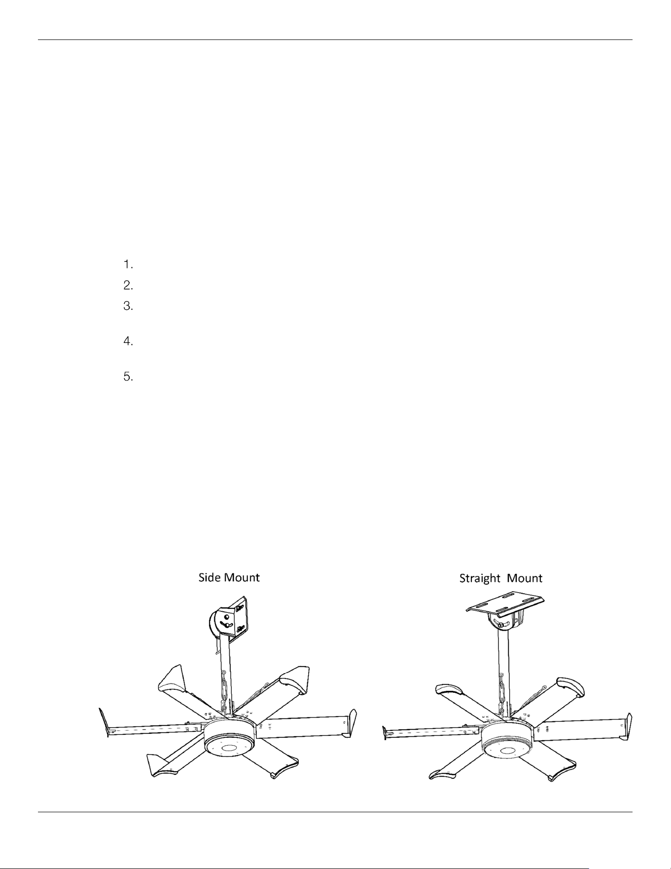
If installing multiple Fans, see figure 5 for spacing required between Fans.
⚠ WARNING T
his equipment has internal arcing or sparking parts that should not be exposed to
flammable vapors.
Always maintain a minimum distance of 50-feet / 15-meters
from any open flame or sparks.
⚠ WARNING Verify the structural framing will support the weight of the HVLS Fan; is well
constructed, and stable enough to prevent the Fan from falling
.
Figure 3 — Vertical Clearances CB-11HVLS and CB-16HVLS
Figure not to scale.
Optimum Ceiling Height:
CB-11HVLS: 17 ft, / 5.2 m
CB-16HVLS: 25 ft. / 7.5 m
Cool Boss Industrial HVLS Fan
13
P/N 5900279 — May 2023 — Rev. A2
Figure 4 — Vertical Clearances CB-20HVLS and CB-24HVLS
The Fan must be mounted directly to the building structure. That structure must be capable of
supporting at least twice the hanging load of the Cool Boss HVLS Fan. Refer to the table
below:
CB HVLS Model Hanging Load Structure must support
CB-11HVLS
152 lbs. / 69 kg 304 lbs. / 138 kg Minimum
CB-16HVLS
209.5 lbs. / 95kg 419 lbs. / 190 kg Minimum
CB-20HVLS
282 lbs. / 128kg 564 lbs. / 256 kg Minimum
CB-24HVLS
295.5 lbs. / 134kg 591 lbs. / 268 kg Minimum
If you are uncertain as to the load bearing capability of the building structure consult a
professional structural engineer.
After installation, the vertical clearance of the Fan Blades and motor should conform to either
figure 3 or 4 based on your Fan model.
The Fan must be mounted so that a person cannot contact the rotating Fan Blades.
Avoid mounting the Fan directly under Skylights or Lighting Fixtures to prevent the creation of
a strobe effect.
Air conditioning or air cooler discharge vents should be located away from the Fan by at least
two-times the diameter of the Fan.
Figure not to scale.
Optimum Ceiling Height:
CB-20HVLS: 30 ft. / 9.1 m
CB-24HVLS: 36 ft. / 10.9 m
Cool Boss Industrial HVLS Fan
14
P/N 5900279 — May 2023 — Rev. A2
Do not place the Fan in an area that can be exposed to wind. Doing so may cause personal
injury, death, or equipment damage.
Do not mount the Fan in an area that may come into contact with water.
When installing multiple HVLS Fans the minimum center to center distance is as detailed in the
table below.
HVLS Model CB-11HVLS CB-16HVLS CB-20HVLS CB-24HVLS
A-Fan
Diameter
11.5 ft. / 3.5 m 16.5 ft. / 5 m 20 ft. / 6.1 m 24 ft. / 7.3 m
B- Min.
Distance
between
HVLS Fans
33 ft. / 10 m 49.25 ft. / 15 m 69 ft. / 21 m 69 ft. / 21 m
⚠ CAUTION To ensure efficient operation, the Cool Boss HVLS requires adequate air flow.
Figure 5
Cool Boss Industrial HVLS Fan
15
P/N 5900279 — May 2023 — Rev. A2
Unbox the Cool Boss HVLS Fan
The Cool Boss HVLS Fan is carefully packaged to prevent damage. Exercise care in removing the Fan
from its packaging.
⚠ WARNING Be careful not to injure yourself on the container’s sharp edges or fasteners.
⚠ WARNING You must wear the proper protective equipment at all times during setup and
assembly of this Fan: leather gloves, steel-toed boots, and back belts.
⚠ WARNING Only properly trained and equipped personnel should be working with the Fan on
elevated work platforms or aerial lifts.
To unbox the Cool Boss HVLS Fan:
Clear the area directly under the Fan mounting location.
Move the personnel lifting equipment into position.
Move the crates containing the Cool Boss Fan near the Fan mounting location. Make sure the
containers will not interfere with the Personnel Lift or rigging equipment.
Use a hammer and pry bar to carefully remove the shipping container from around the Cool
Boss components.
Verify all components are undamaged. Do not install damaged Fan Blades or mating
components.
⚠ WARNING Damaged components, when rotating under load, can break unpredictably and
cause damage to the Fan and personal injury to those nearby.
Mount the Fan Brackets
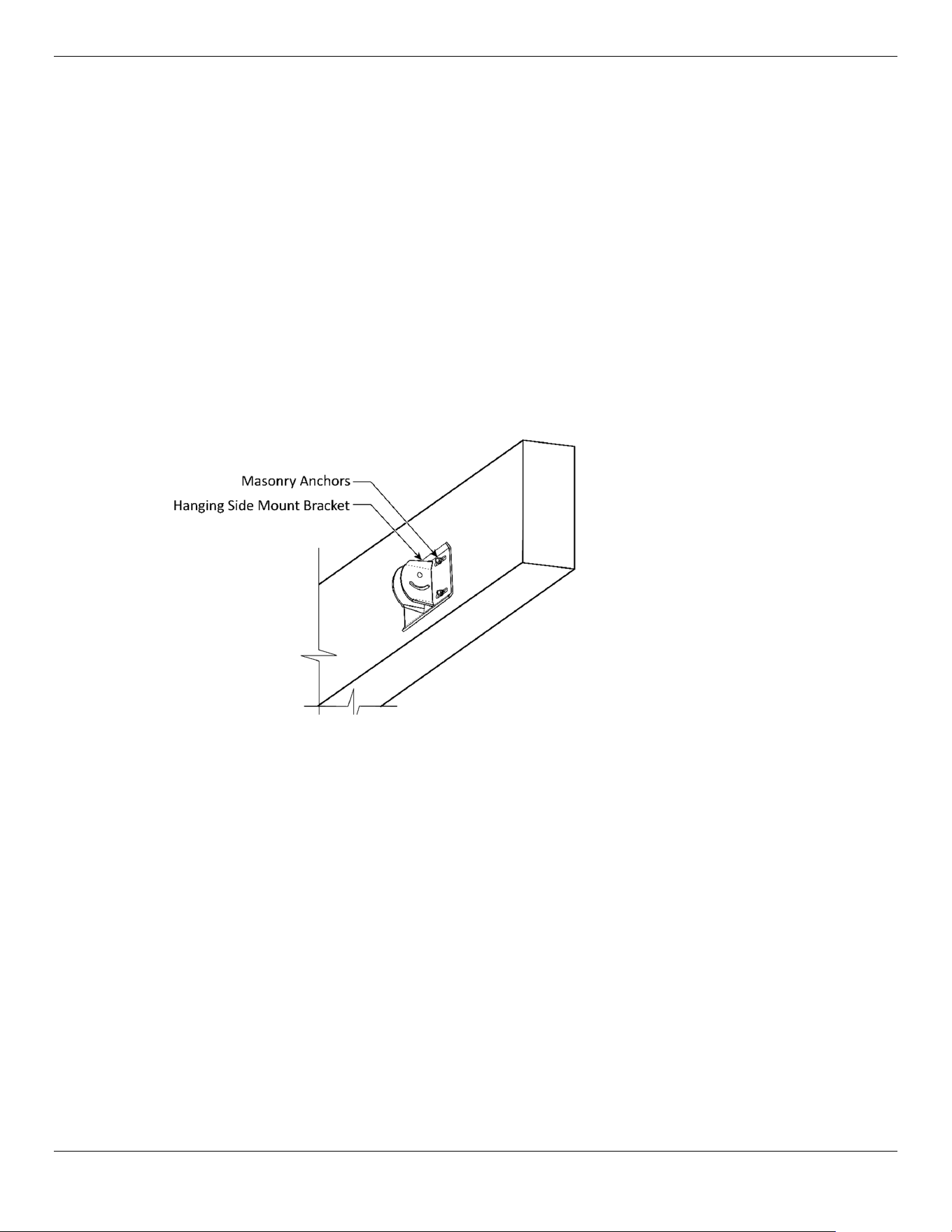
The Cool Boss HVLS Fan is typically mounted on structural members, typically Steel Reinforced
Concrete Beams or Structural Steel I-Beams. There are two basic mounting methods, a Side Hanging
Mount and a Straight Hanging mount are available using the brackets provided.
Figure 6
Cool Boss Industrial HVLS Fan
16
P/N 5900279 — May 2023 — Rev. A2
⚠ WARNING The Cool Boss HVLS Fan is heavy and awkward to work with. Installation should be
accomplished by competent personnel ensuring the Fan is properly rigged and
balanced for lifting. Installation personnel should have knowledge, training, and
experience in lifting, rigging, and securing heavy objects overhead.
⚠ WARNING Block off the area under the installation site. Do not allow personnel to walk near or
under the area while work aloft is underway.
⚠ WARNING You must wear the proper protective equipment at all times during setup and
assembly of the HVLS Fan: eye protection, head protection, leather gloves, steel-
toed boots, back belts, including a proper harness and tie-in equipment for fall
protection while working overhead.
To mount the HVLS Fan on a Reinforced Concrete Beam (Hanging Side Mount):
1. Verify the mounting location satisfies the location and clearance criteria called out in the previous
section, Find a location for your Cool Boss HVLS Fan.
2. Verify the Structural Beam can support the weight of the Cool Boss Fan.
3. Retrieve the Hanging Side Mount Bracket and 12 mm or 16 mm Masonry Anchors.
4. Using the Bracket as a template, mark the hole locations on the Beam, then drill holes for the
Expansion Anchors using an appropriate Drill Bit. Drill the holes straight and perpendicular to the
beam.
5. Use a vacuum or compressed air to thoroughly clear the debris from the hole. Do not make the
holes any larger than necessary. Refer to figure 9.
6. Cover the Anchor end threads with a Hex Nut and carefully tap the Anchors into the holes.
To mount the Cool Boss HVLS Fan on a Reinforced Concrete Beam (Straight Mount):
1. Verify the mounting location satisfies the location and clearance criteria called out in the previous
section, Find a location for your Cool Boss HVLS Fan.
2. Verify the Structural Beam is capable of supporting the weight of the Cool Boss Fan.
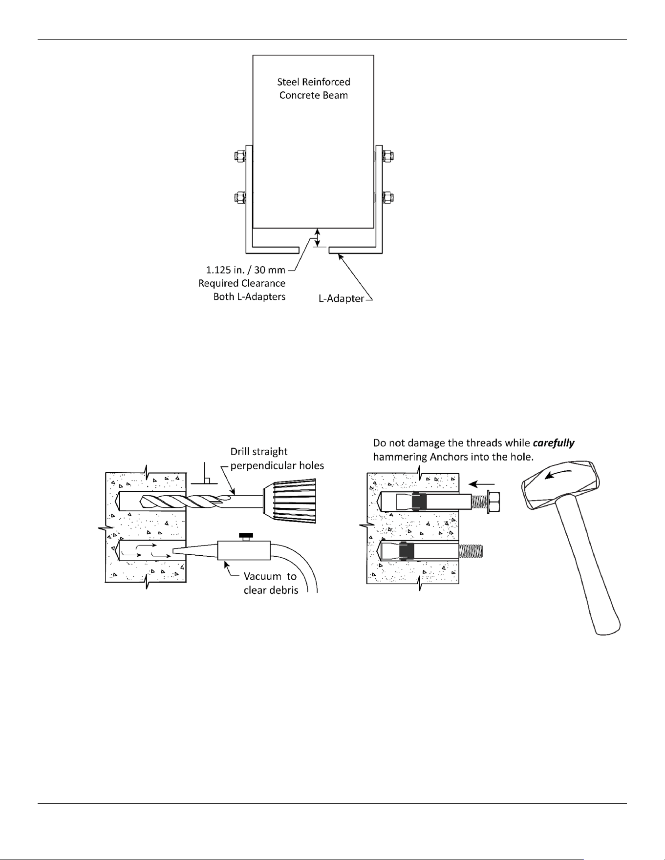
3. Retrieve the two L-Adapters and 12 mm x 100 mm Expansion Anchors with Lock Washers, Flat
Washers, and Hex Nuts.
4. Place the L-Adapters against the Beam and adjust their position until a 1.125 in. / 30 mm
clearance is achieved between the Bracket and the Beam. Refer to figure 8.
Figure 7
Cool Boss Industrial HVLS Fan
17
P/N 5900279 — May 2023 — Rev. A2
5. Using the L-Shaped Adapter as a template, mark the hole locations on the Beam, then drill Ø12
mm holes for the Expansion Anchors using a Masonry Drill Bit. Drill the holes straight and
perpendicular to the beam.
6. Use a vacuum or compressed air to thoroughly clear the debris from the hole. Do not make the
holes any larger than necessary Refer to figure 9.
7. Cover the Anchor end threads with a Hex Nut and carefully tap the Anchors into the holes.
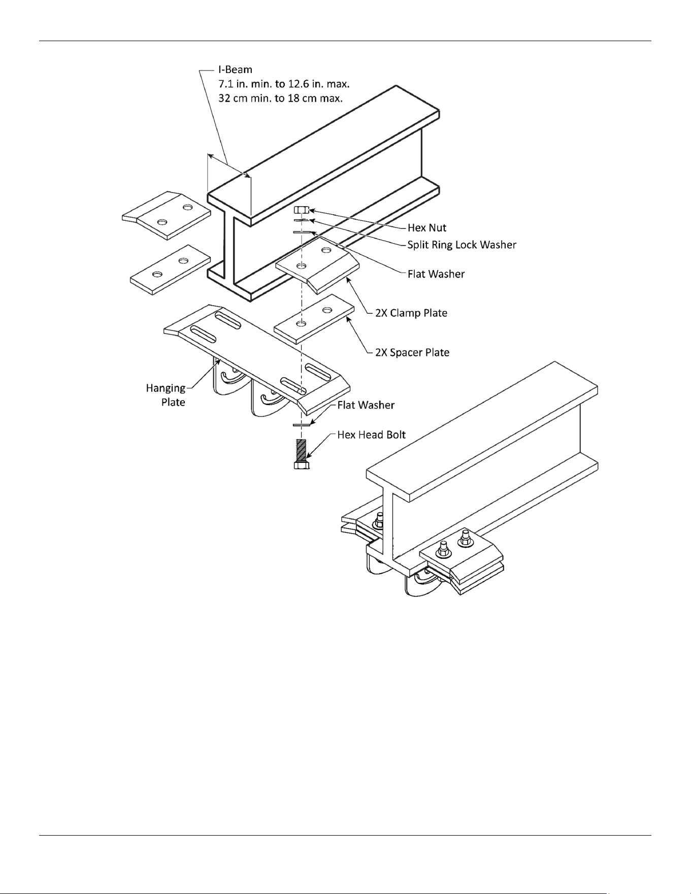
8. Install each L-Adapter with four Flat Washers, Lock Washers, and Hex Nuts. Refer to figure 10.
9. Install the Hanging Plate using four M16 x 60 Bolts, Flat Washers, Split Ring Lock Washers, and
Hex Nuts. Refer to figure 10.
Figure 8
Figure 9
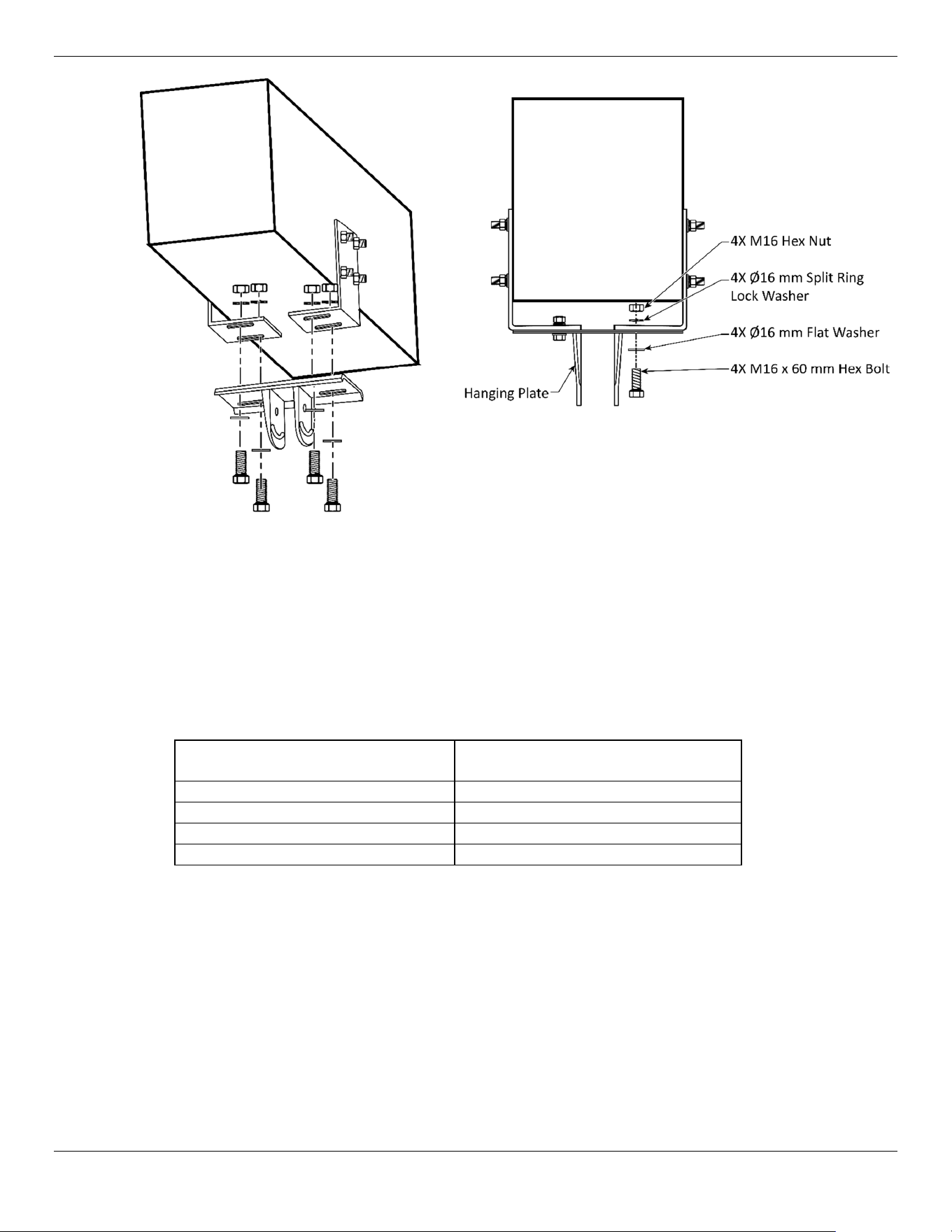
Cool Boss Industrial HVLS Fan
18
P/N 5900279 — May 2023 — Rev. A2
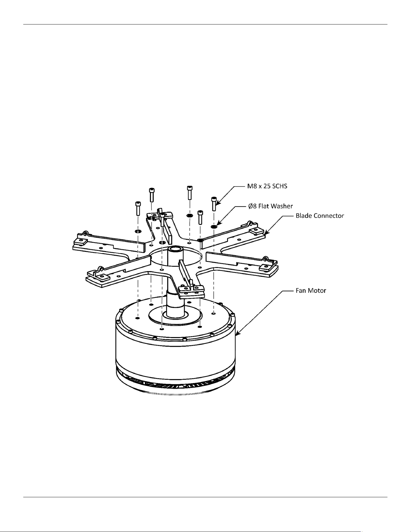
To mount the Cool Boss HVLS Fans to a Streel I-Beam:
1. Verify the mounting location satisfies the location and clearance criteria called out in the previous
section, Find a location for your Cool Boss HVLS Fan.
2. Verify the Structural Beam is capable of supporting the weight of the Cool Boss Fan.
3. Retrieve the Clamping Plate, the Spacer Plate, and the Hanging Plate.
4. Retrieve the fasteners detailed in the table below based upon your Cool Boss Fan Model. Refer to
figure 11 and the table below:
CB-11HVLS
CB-16HVLS
CB-20HVLS
CB-24HVLS
4 ea. M12 Hex Nuts 4 ea. M16 Hex Nuts
4 ea. Ø12 Split Ring Lock Washer 4 ea. Ø16 Split Ring Lock Washer
8 ea. Ø12 mm Flat Washer 8 ea. Ø16 mm Flat Washer
4 ea. M12 x 60 mm Hex Head Bolt 4 ea. M16 x 60 mm Hex Head Bolt
Figure 10
Cool Boss Industrial HVLS Fan
19
P/N 5900279 — May 2023 — Rev. A2
Figure not to scale.
Figure 11
Cool Boss Industrial HVLS Fan
20
P/N 5900279 — May 2023 — Rev. A2
Attach the Blade Connector to the Motor (CB-11 Only)
The CB-11HVLS Fans utilize a Blade Connector that must be attached to the Fan Motor. Skip to the
next section if you are installing a CB-16HVLS, CB-20HVLS or CB-24HVLS.
To install the Blade Connector on the CB-11HVLS Fan Motor:
1. Refer to figure 12, and retrieve the following:
a. The Fan Motor
b. The Blade Connector
c. 6 ea. M8 x 25 mm Socket Head Cap Screws
d. 6 ea. Ø8 Flat Washers
2. Place the Blade Connector on the Fan Motor and secure using the Flat Washers and Socket Head
Cap Screws. Tighten securely. Refer to figure 12 below.
Figure not to scale.
Figure 12
Cool Boss Industrial HVLS Fan
21
P/N 5900279 — May 2023 — Rev. A2
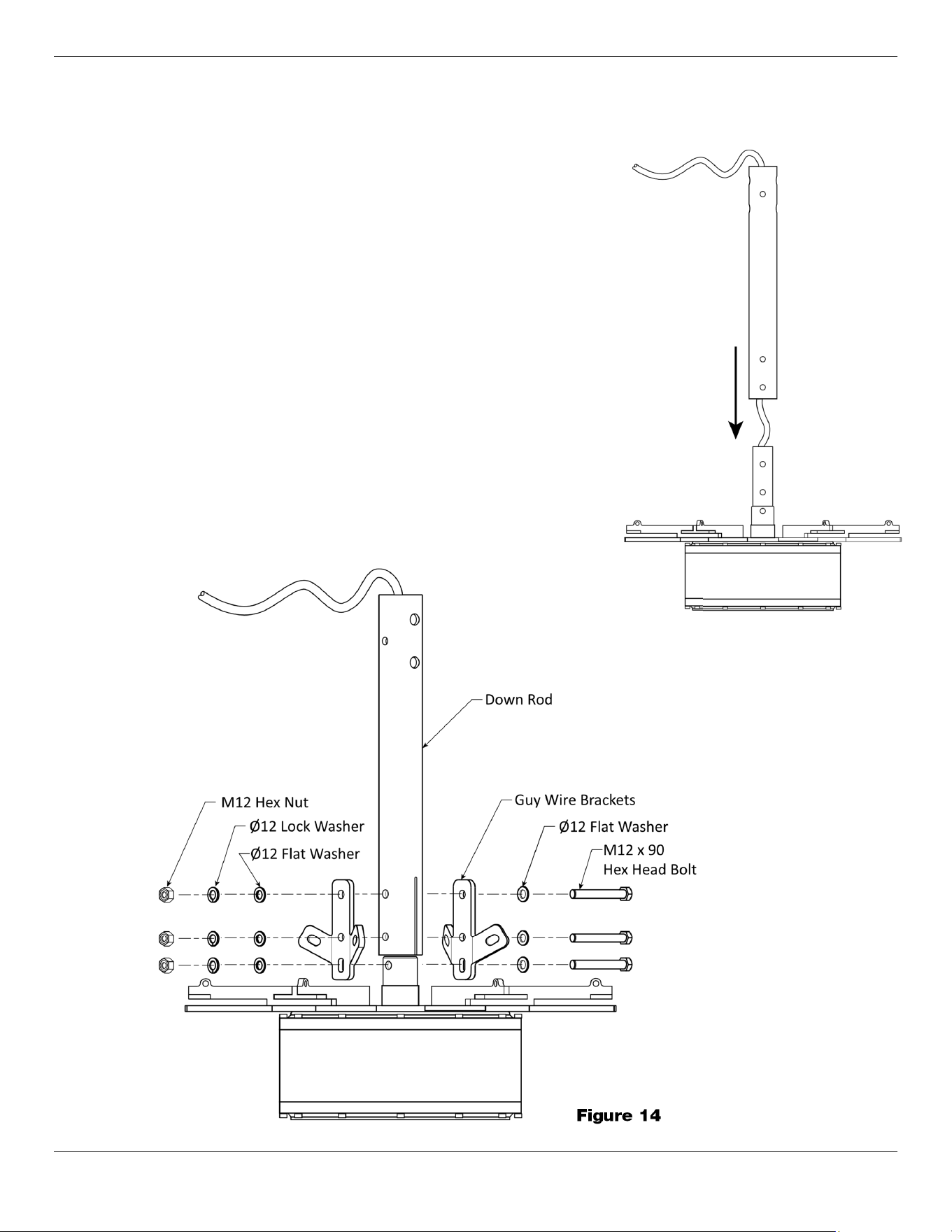
Install the Fan on its Down Rod
The Fan Motor must be connected to its Down Rod and the Guy Wire Brackets which provide Guy
Wire attachment points.
To install the Fan Motor on its Down Rod:
1. Retrieve the following:
a. Down Rod
b. 2 ea. Guy Wire Brackets
c. 3 ea. M12 x 90 mm Hex Head Bolts
d. 3 ea. M12 x 90 mm Hex Head Bolts
e. 6 ea. Ø12 Flat Washer
f. 3 ea. Split Ring Lock Washer
g. 3 ea. M12 Hex Nut
2. Feed the Control Cable through the Down Rod then
carefully slide the Down Rod over the Fan’s Center Shaft.
Refer to figure 13.
3. Attach the Guy Wire Mounting Brackets to the Main Shaft
as detailed in figure 14.
Figure 13
Figure 14
Cool Boss Industrial HVLS Fan
22
P/N 5900279 — May 2023 — Rev. A2
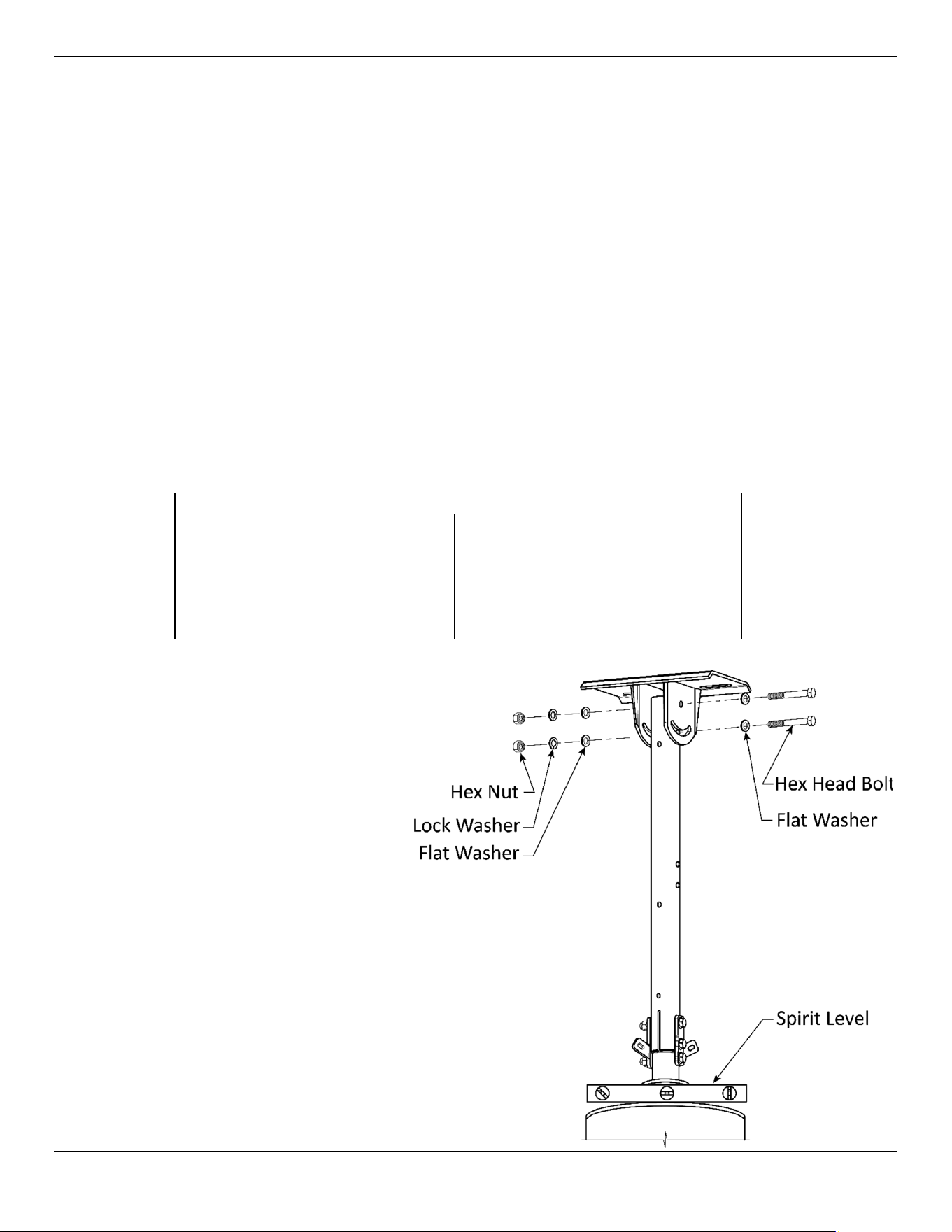
Install the Fan on its Hanging Plate
The Fan Motor must be connected to its Down Rod and the Guy Wire Brackets which provide Guy
Wire attachment points.
⚠ WARNING The Cool Boss HVLS Fan is heavy and awkward to work with. Installation should be
accomplished by competent personnel ensuring the Fan is properly rigged and
balanced for lifting. Installation personnel should have knowledge, training, and
experience in lifting, rigging, and securing heavy objects overhead.
⚠ WARNING Block off the area under the installation site. Do not allow personnel to walk near or
under the area while work aloft is underway.
⚠ WARNING You must wear the proper protective equipment at all times during setup and
assembly of the HVLS Fan: eye protection, head protection, leather gloves, steel-
toed boots, back belts, including a proper harness and tie-in equipment for fall
protection while working overhead.
To connect the Fan Down Rod to the Hanging Bracket:
1. Retrieve the fasteners detailed in the table below based upon your Cool Boss Fan Model:
Fasteners
CB-11HVLS
CB-16HVLS
CB-20HVLS
CB-24HVLS
2 ea. M12 Hex Nuts 2 ea. M16 Hex Nuts
2 ea. Ø12 Split Ring Lock Washer 2 ea. Ø16 Split Ring Lock Washer
4 ea. Ø12 mm Flat Washer 4 ea. Ø16 mm Flat Washer
2 ea. M12 x 90 mm Hex Head Bolt 2 ea. M16 x 90 mm Hex Head Bolt
2. Verify the Fan’s Control
Cable will not be damaged
as the Fan is hoisted into
position.
3. Safely hoist the Fan Motor
with its Down Rod up to the
Hanging Bracket.
4. Secure the Fasteners finger
tight as indicated in
figure 15.
5. Place a Spirit Level on top of
the Fan Motor and adjust the
Motor to hang level to the
ground. Tighten the Hex
Head Bolts to secure the Fan
Motor.
Figure 15
Cool Boss Industrial HVLS Fan
23
P/N 5900279 — May 2023 — Rev. A2
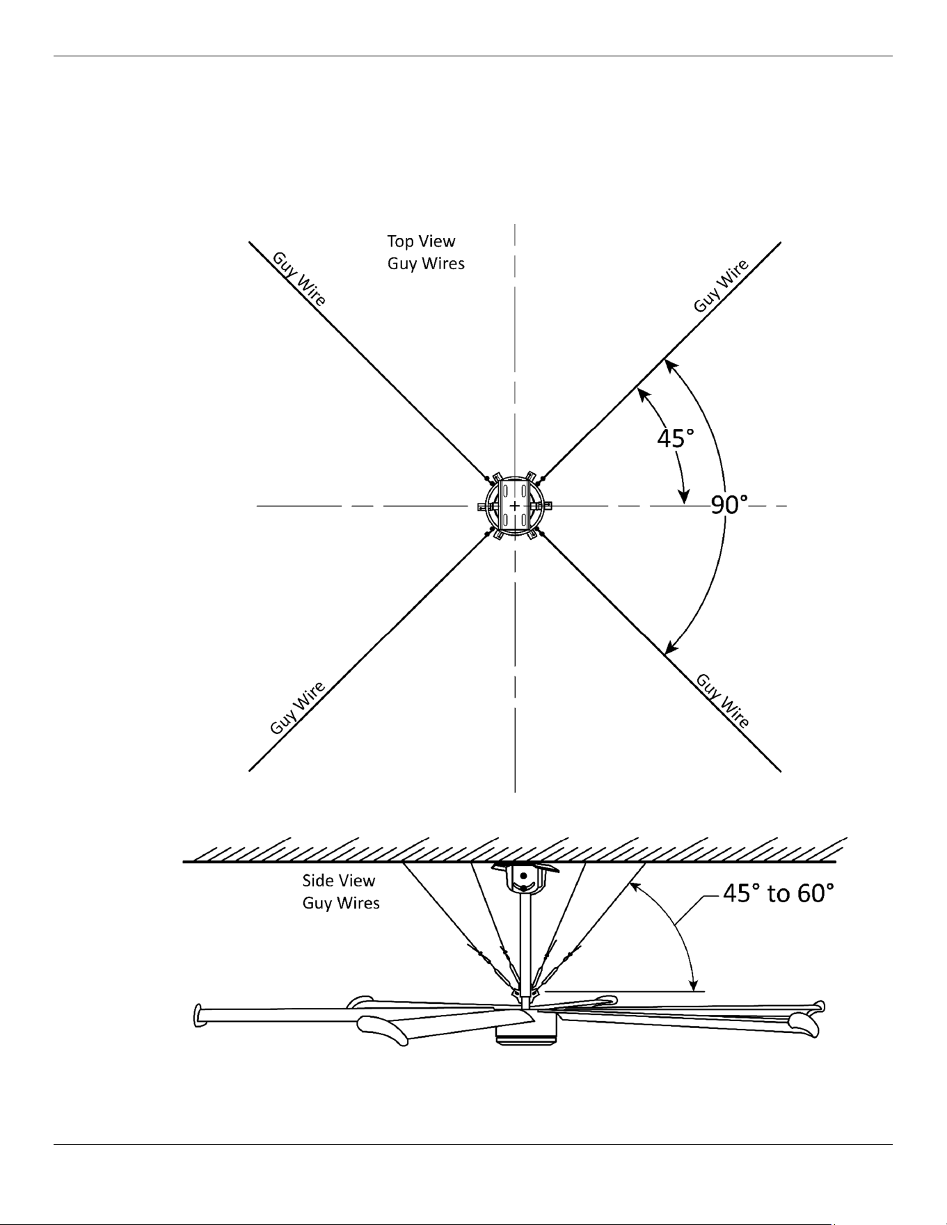
Install the Guy Wires and Leveling the Fan
The Guy Wires are wire rope cables used to steady and support the Fan structure during the torque
created at start-up and any small oscillations encountered during normal operation. Four Guy Wires
are attached between Brackets on the Fan Down Rod and fixed points on the building structure.
Turnbuckles are used to adjust the tension on the Guy Wires and will also affect the level of the Fan
motor.
Figure 16
Cool Boss Industrial HVLS Fan
24
P/N 5900279 — May 2023 — Rev. A2
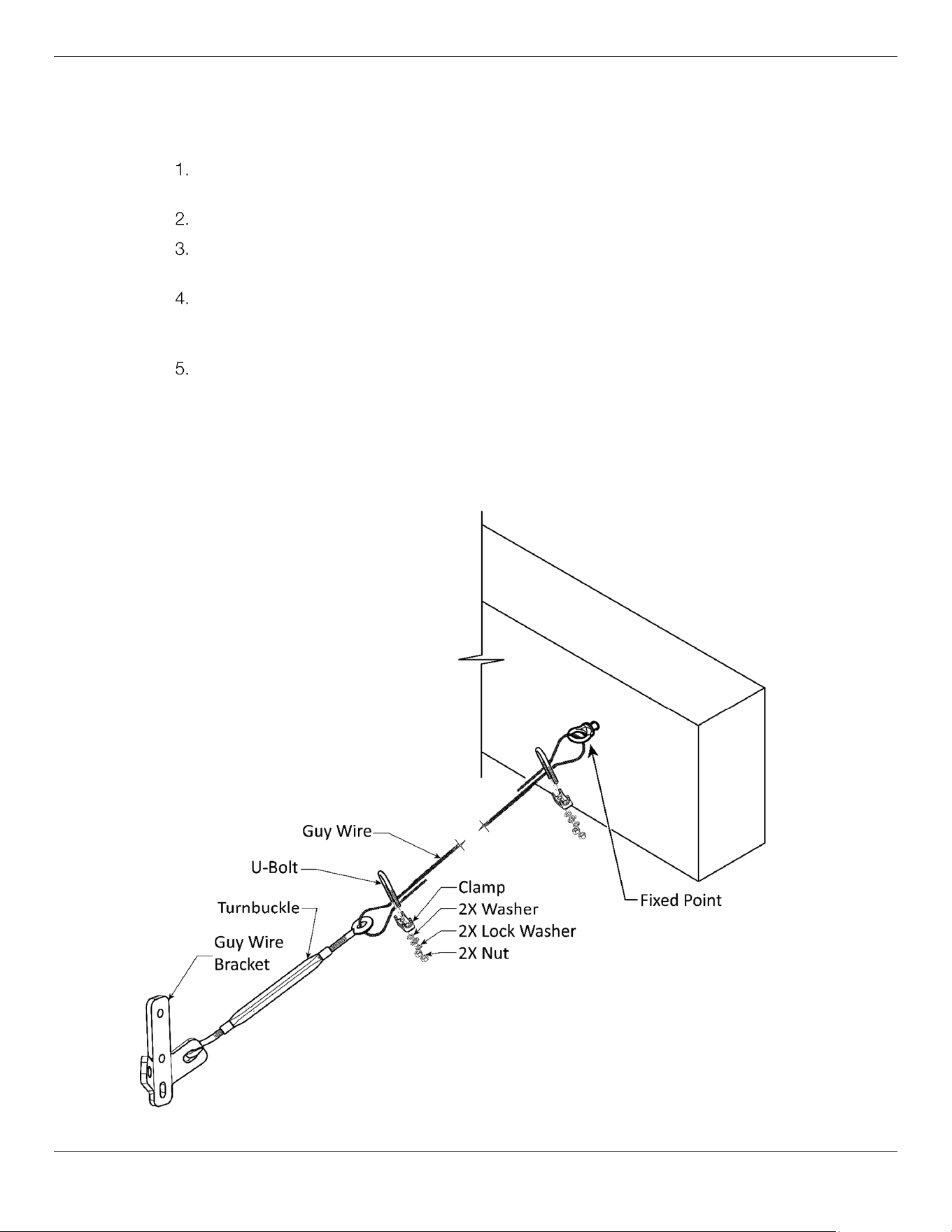
To Install the Guy Wires and Level the Fan Motor:
Locate and prepare the four fixed points that will be used to anchor the Guy Wires. The ideal angle
between Guy Wires is 90°. Refer to figure 16.
Use an Eyebolt or similar as the Fixed-Point Anchor. Verify the structure is capable of
supporting the Guy Wire load without damaging the structure or pulling free of the structure.
Attach the Turnbuckle to the Guy Wire Bracket.
Loop one end of the Guy Wire through the Turnbuckle’s Eyebolt and secure with the U-Bolt,
Clamp, Washer, Lock Washer, and Hex Nut.
Loop the other end of the Guy Wire through the Fixed Point remove any slack and secure as
in step 4 above. Repeat this process to install the three remaining supporting Guy Wires.
Refer to figure 17.
After installing all Guy Wires, place a level on the top of the Fan Motor and use the
Turnbuckles to adjust the tension on each Wire. The goal is to have the Fan Motor Level with
a moderate amount of tension on each wire to ensure it is balanced and will compensate for
any oscillation upon start-up or during speed changes in normal operation.
⚠ WARNING Do not operate this Fan if it is unlevel or out of balance. Rebalance and level or
contact Cool Boss at (805) 933-9970, email at [email protected].
Figure 17
Cool Boss Industrial HVLS Fan
25
P/N 5900279 — May 2023 — Rev. A2
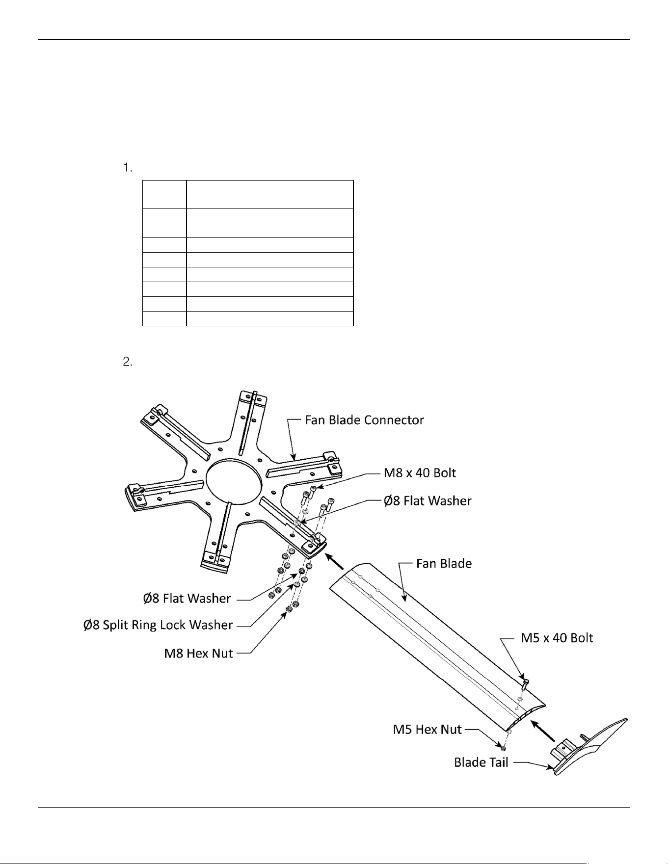
Install the Fan Blades (CB-11HVLS Only)
The Fan Blades are a critical component. If the Blades are bent or damaged, do not install. There are
minor differences in the attachment of the Blades based on the model of the specific Fan. Use the
procedure that applies to your Model of the Cool Boss HVLS Fan.
⚠ WARNING Do not operate this Fan if the Blades are bent or damaged.
Retrieve the following components:
Qty. Description
6 Fan Blade
6 Blade Tail
24 M8 x 40 Bolt
48 Ø8 Flat Washer
24 Ø8 Split Ring Lock Washer
24 M8 Hex Nut
6 M5 x 40 Bolt
6 M5 Hex Nut
Attach the six Fan Blades to the Blade Connector using the fasteners as detailed in
figure 18 below. Take care not to damage the Blades during the installation.
Figure 18
Cool Boss Industrial HVLS Fan
26
P/N 5900279 — May 2023 — Rev. A2
Install the Fan Blades
CB-16HVLS, CB-20HVLS and CB-24HVLS
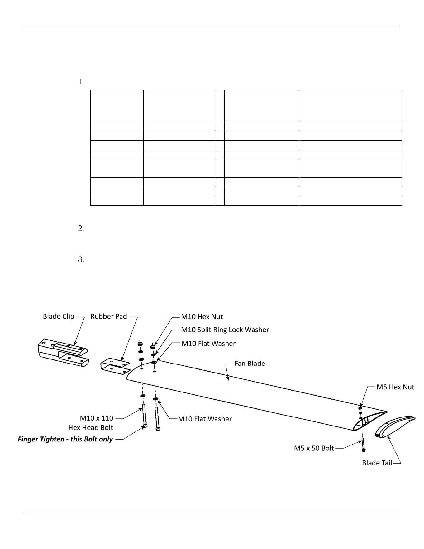
To Install the Fan Blades:
Retrieve the following components:
CB-16HVLS
Qty.
Description CB-20HVLS and
CB-24HVLS
Qty.
Description
6 Fan Blades 5 Fan Blades
6 Blade Tails 5 Blade Tails
12 M10 x 110 Bolt 10 M10 x 110 Bolt
24 M10 Flat Washer 20 M10 Flat Washer
12 M10 Split Ring
Lock Washer
10 M10 Split Ring Lock Washer
12 M10 Hex Nut 10 M10 Hex Nut
6 M5 x 40 Bolt 5 M5 x 40 Bolt
6 M5 Hex Nut 5 M5 Hex Nut
Assemble each of the Fan Blades to a Blade Clip with a Rubber Pad using the fasteners as
detailed in figure 19. Leave the innermost M10 x 110 mm Bolt finger tight on all Blade
assemblies. This Bolt will be tightened after adding the Arc Plate Supports.
Attach the Blade Tail as detailed below.
IMPORTANT! Leave the innermost M12 Hex Head Bolt finger tight on all
assemblies.
Components removed for clarity. Figure not to scale.
Figure 19
Cool Boss Industrial HVLS Fan
27
P/N 5900279 — May 2023 — Rev. A2
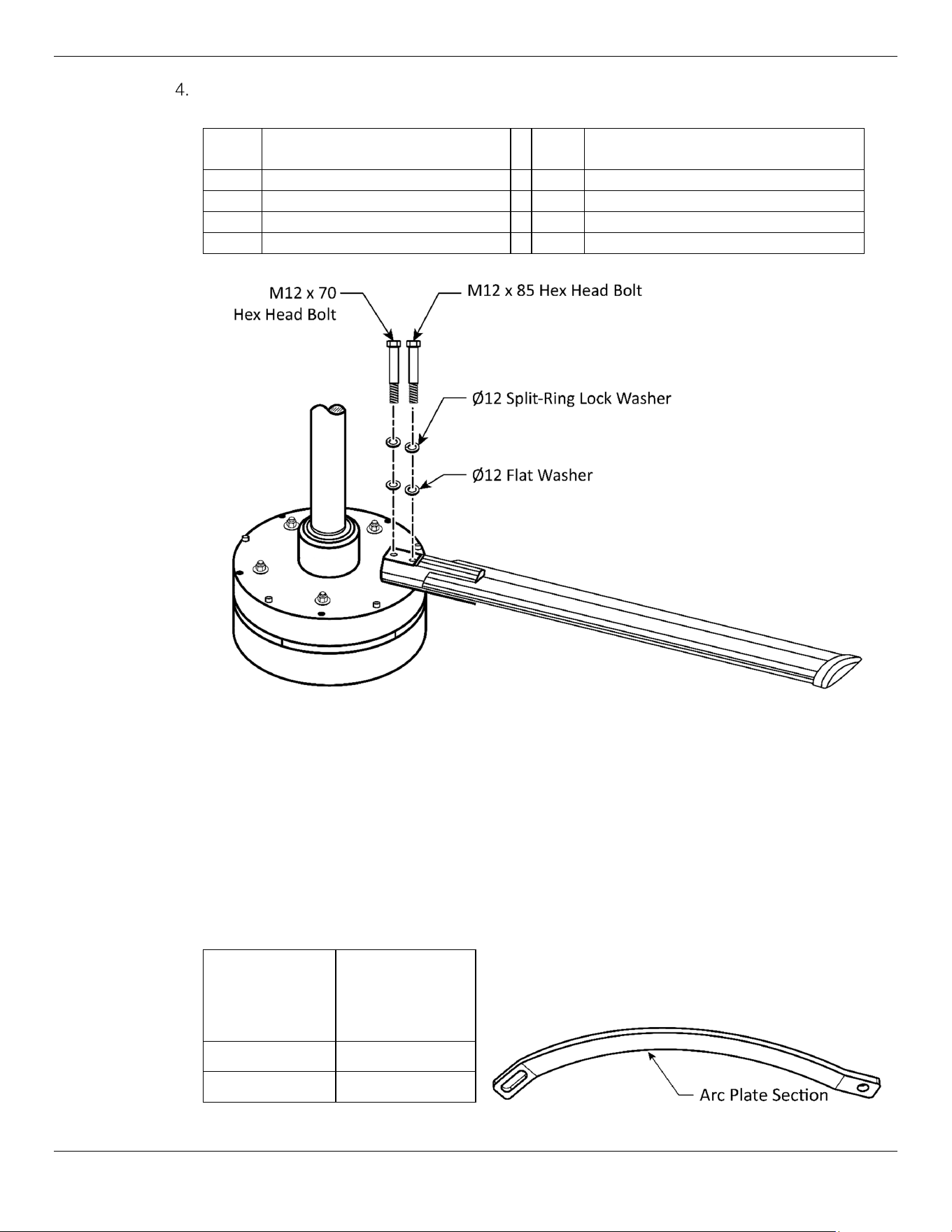
Attach the Blade Assembly to the Fan Motor at the Blade Clip as detailed in figure 20.
Assembly will require:
Qty. CB-16HVLS
Description
Qty. CB-20HVLS and CB-24HVLS
Description
6 M12 x 85 mm Hex Head Bolt 5 M12 x 85 mm Hex Head Bolt
6 M12 x 70 mm Hex Head Bolt 5 M12 x 70 mm Hex Head Bolt
12 Ø12 Split-Ring Lock Washer 10 Ø12 Split-Ring Lock Washer
12 Ø12 Flat Washer 10 Ø12 Flat Washer
Components removed for clarity. Figure not to scale.
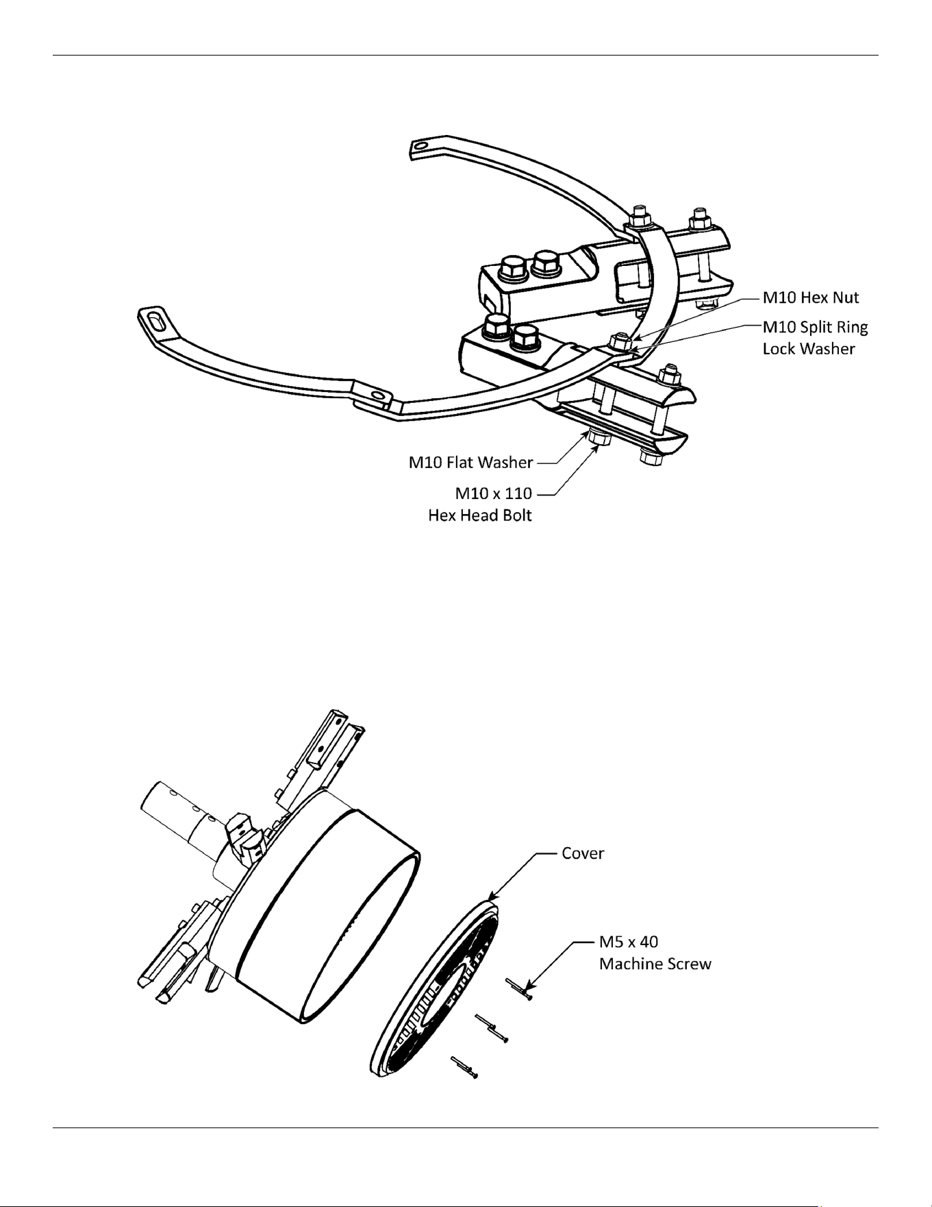
Install the Arc Plate Sections
CB-16HVLS, CB-20HVLS and CB-24HVLS
The Arc Plates serve to connect and solidify the Fan Blade structure.
To Install the Arc Plate Sections:
1. Retrieve the Arc Plate Sections for your Fan Model. Refer to figure 20.
Fan Model
Number of
Arc Plate
Sections
required
CB-20HVLS
5
CB-24HVLS
5
Figure 20
Cool Boss Industrial HVLS Fan
28
P/N 5900279 — May 2023 — Rev. A2
2. Install the Arc Plate Sections onto the Fan and secure fasteners as detailed in figure 21.
Components removed for clarity. Figure not to scale.
Install the Cover
Install the cover as detailed in figure 22.
Components removed for clarity. Figure not to scale.
Figure 21
Figure 22
Cool Boss Industrial HVLS Fan
29
P/N 5900279 — May 2023 — Rev. A2
Install the Control and Connect to Power
⚠ DANGER All electrical work must be accomplished by a licensed Electrician, in
accordance with national, state, and local electrical codes. If you do not use a
licensed Electrician, you void your warranty and put everyone who uses the Fan in
danger of injury or, in rare cases, death.
⚠ WARNING Do not change any of the operating parameters of the Variable Frequency Drive
(VFD). This HVLS Fan is configured at the factory and changing VFD parameters
may cause damage that is not covered under warranty.
⚠ WARNING Do not install the HVLS Fan control in an area subjected to high temperatures,
direct sunlight and or inflammables.
To connect the Cool Boss HVLS Fan to Power:
Before connecting the Fan Control to a power source, Lock-Out the power at the Electrical
Service Panel to ensure it cannot be re-energized while work is being conducted.
Verify the required 220VAC, Single Phase, 50/60 Hz., electrical power at the following current
is available for the following Fan models:
CB-11HVLS CB-16HVLS CB-20HVLS CB-24HVLS
208-230VAC,
5 Amps, 50/60 Hz.,
1 Ph.
208-230VAC,
5 Amps, 50/60 Hz.,
1 Ph.
208-230VAC,
7 Amps, 50/60 Hz.,
1 Ph.
208-230VAC,
7 Amps, 50/60 Hz.,
1 Ph.
Attach the Fan Control to a wall or column where it will be protected from direct sunlight,
excessive heat, traffic, or collisions with equipment.
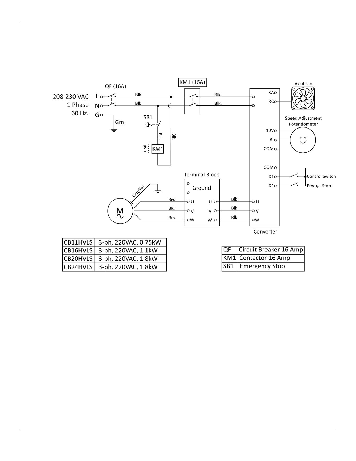
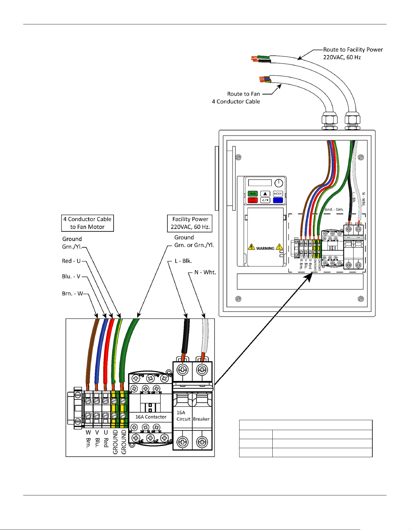
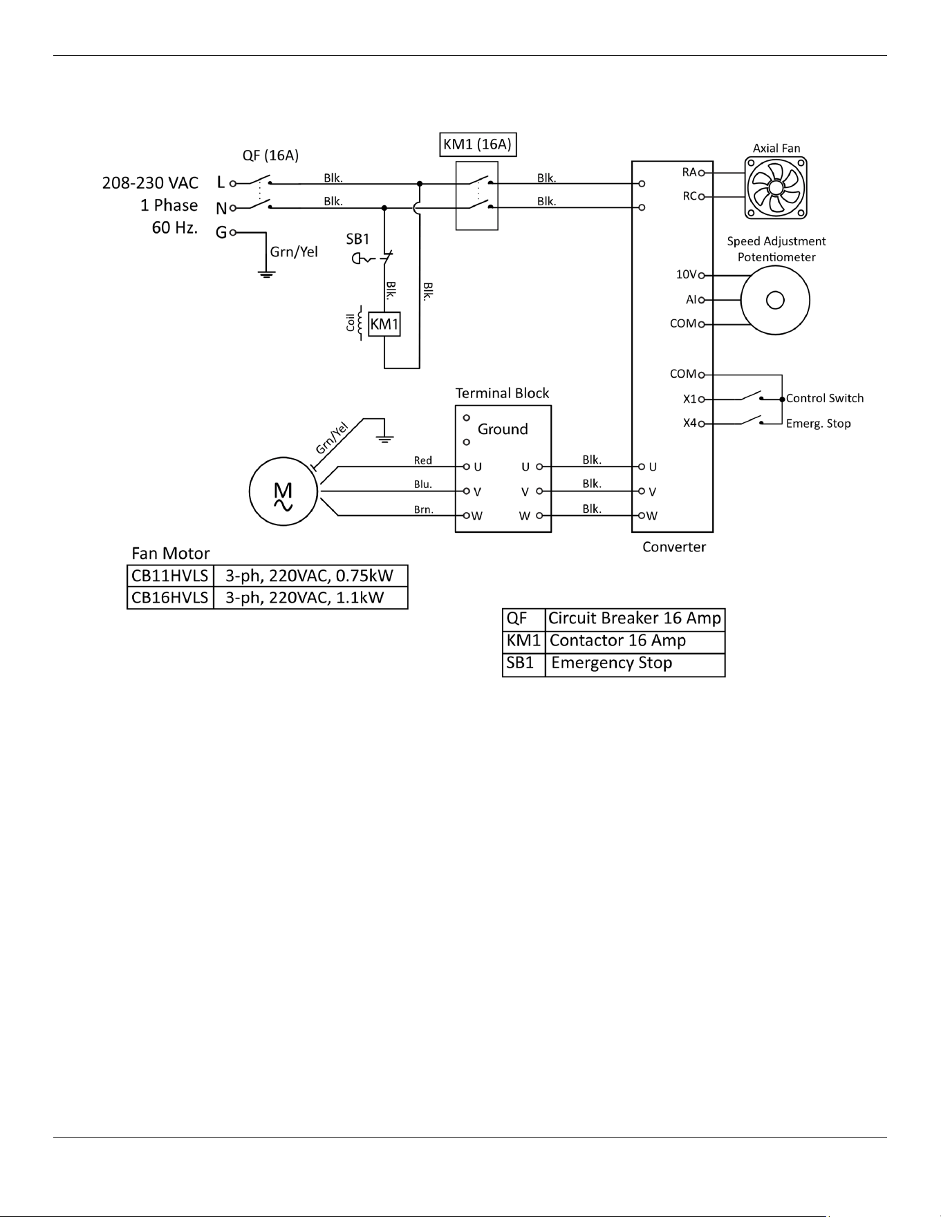
Refer to the Schematic and Wiring Diagram in this manual and on the inside cover of the
Control.
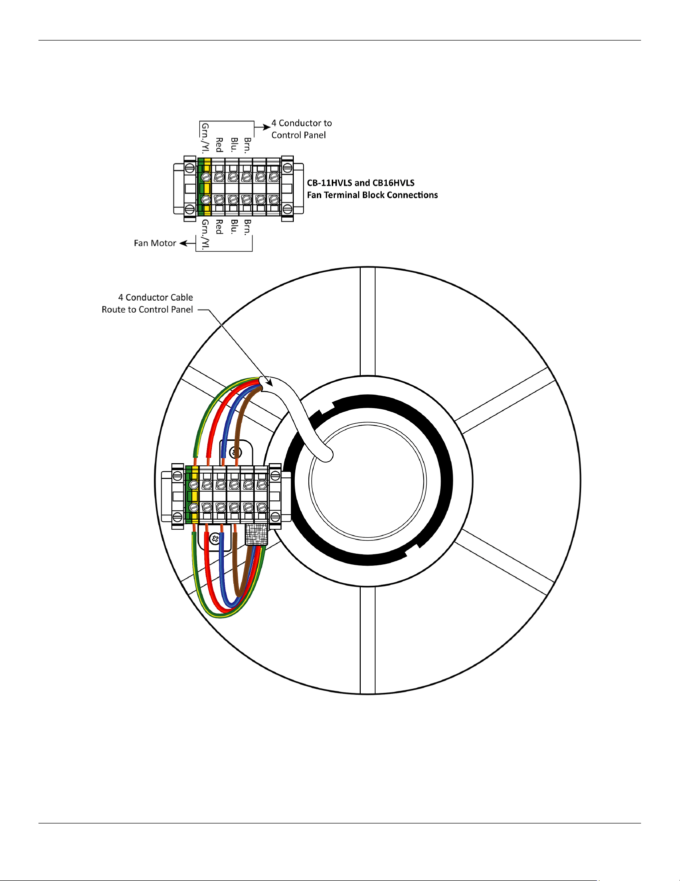
Models CB-11 and CB-16 include approximately 80-feet / 25 m of 4-conductor cable with the
Fan. Route, protect and secure the 4-Conductor Cable from the Fan Motor to the Control
Box. All wiring is to conform to national, state, and local electrical codes.
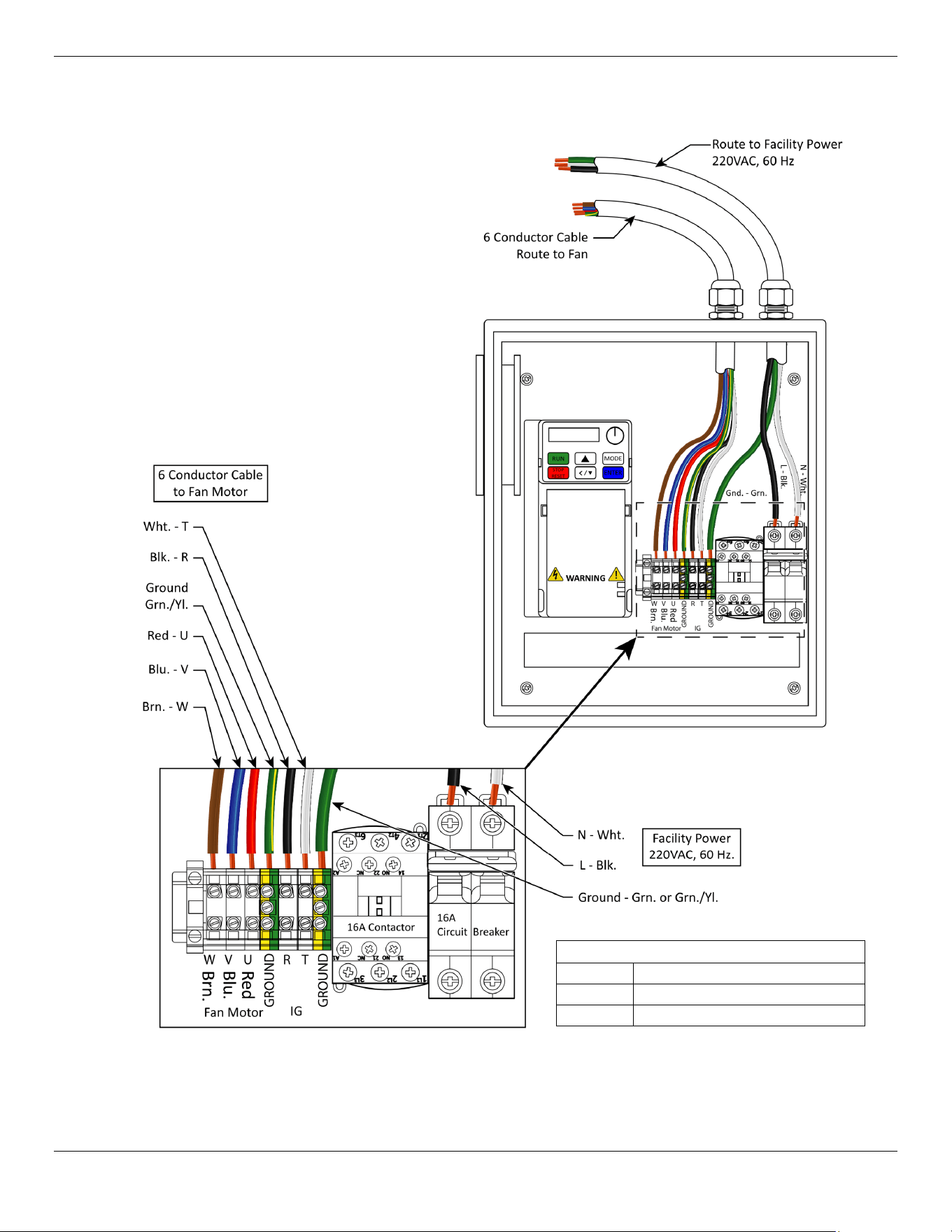
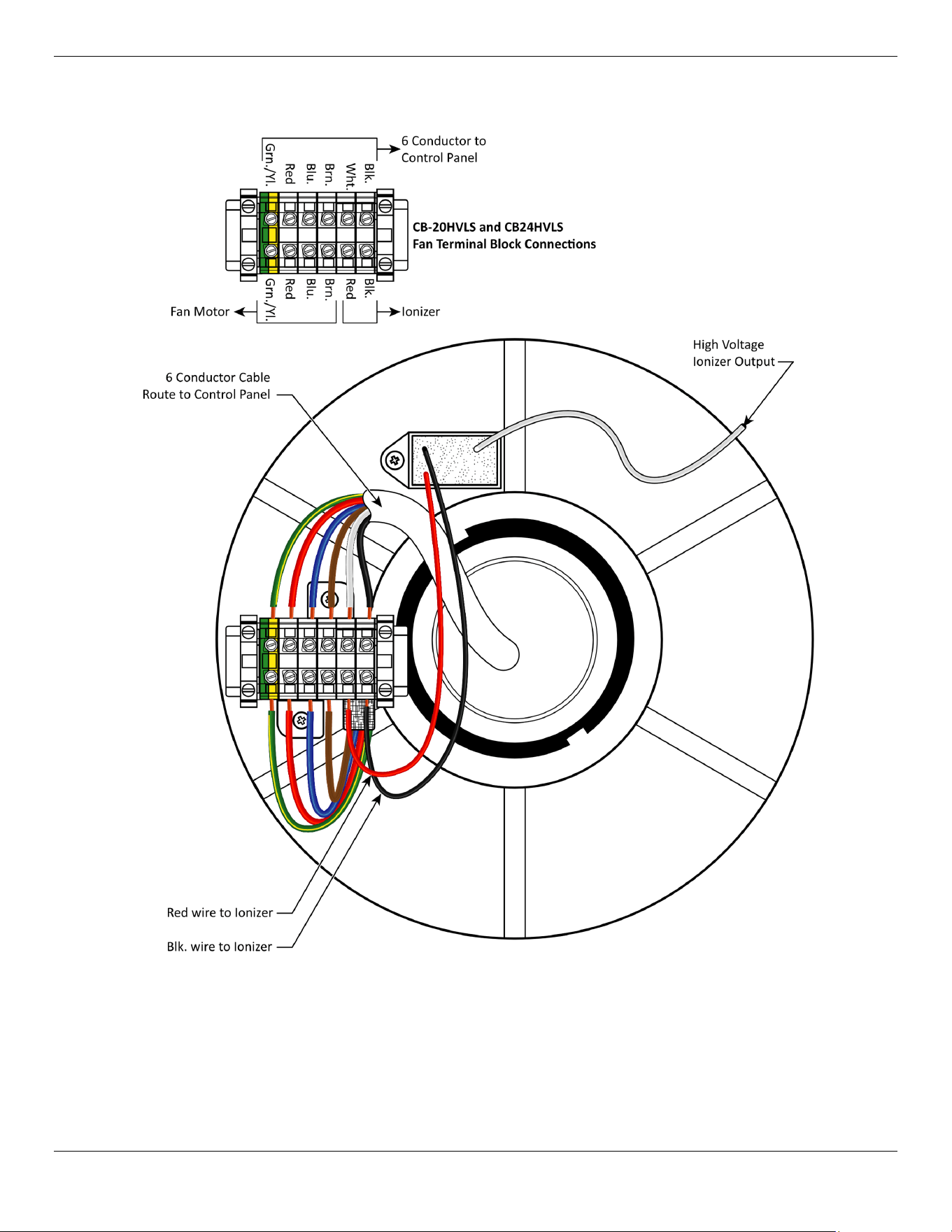
Models CB-20 and CB-24 include approximately 80-feet / 25 m of 6-conductor cable. Route,
protect and secure as above.
Connect the Control Cable wiring to the Fan Motor Barrier Strip as indicated in the Wiring
Diagram for your Fan model.
Route, protect and secure 220VAC Electrical Power from the facility’s electrical service
protected by an appropriately rated circuit breaker to the Control as indicated by the Wiring
Diagram.
Additional electrical information:
Damage caused by improper electrical installation (such as not grounding the unit) voids the
warranty.
⚠ DANGER After removing power from the Fan, even if the main Fan Motor is
disconnected, hazardous voltage may be present on the circuit
terminals. Verify terminals are safe with a Voltmeter before beginning work. For
your safety, do not begin work on the wiring until the voltage drops to a safe level.
Cool Boss Industrial HVLS Fan
30
P/N 5900279 — May 2023 — Rev. A2
Repairing or installing wiring when residual voltage is present may cause sparking,
severe injury, or death.
⚠ DANGER
All units must be grounded to a common ground terminal to prevent damage from
lightning, electrical shock, and to reduce EMF noise interference.
⚠ WARNING
Disconnect power before performing any troubleshooting or maintenance. Make sure
the unit cannot be re-energized until you have completed maintenance or
troubleshooting
.
⚠ WARNING For generator users and or areas with frequent brownout conditions.
Motor failure due to excessive high or low voltage is not covered under warranty. If you
plan to use the Cool Boss HVLS Fan with a Generator or operate in an area with
frequent brownouts, verify that the power source can provide the required current and
voltage. While voltage variations are common (±5%) both high and low voltage
episodes in excess of 15% to 20% can cause Electric Motor overheating and
premature Motor failure.
Low voltage will cause the Motor to draw more electrical current to deliver the same
amount of force to the Fan Blades. Excessive current overheats the Motor Windings,
eventually burning through the insulation and resulting in complete Motor failure.
High voltage episodes can cause premature failure of electrical and electronic
components due to overheating.
Final Installation Checklist
☐ Installation location satisfies the requirements listed in this manual as well as any national, state,
and local building codes.
☐ Mount Fan Brackets.
☐ Mount Fan Blade Connector Bracket (CB-11 Only).
☐ Mount Fan Motor on its Down Rod.
☐ Mount Fan Motor on its Hanging Plate.
☐ Install Guy Wires and level the Fan Motor.
☐ Install Fan Blades on the connector bracket, CB-11 only.
☐ Install the Fan Blades on the Clips and the Fan Motor (CB-16, CB-20 and CB-24HVLS).
☐ Install the Arc Plate Sections CB-16, CB-20, and CB-24HVLS only.
☐ Install the Control.
☐ Route, protect and secure the control cable between the Control and the Fan Motor (Electrician
required).
☐ Make all connections on the motor and control terminal strips (Electrician required).
☐ Install the Cover on the Fan Motor.
☐ Connect the Control to facility Electrical Power (Electrician required).
☐ Complete Operational Test for function.
☐ Leave the Installation and Operation Manual with the Fan Owner/Operator.
Cool Boss Industrial HVLS Fan
31
P/N 5900279 — May 2023 — Rev. A2
Operational Test
Before starting the Cool Boss, verify that the Fan is undamaged, and no obstructions will
interfere or create a hazard with its operation.
Rotate the Variable Speed Adjustment control counterclockwise to its lowest speed
position.
Rotate the Control Switch to the On position.
Verify there are no error codes displayed on the Fan VFD Control. If error codes are present,
Rotate the Control Switch to the Off position and refer to the Troubleshooting section.
Rotate the Variable Speed Adjustment slowly clockwise until the Fan is moving at a slow
speed.
Observe the Fan to verify it is turning in a clockwise direction when viewed from the ground.
Observe the Fan operation to verify that there is no excessive shaking or wobbling and the
Fan is operating safely in all respects. If the Fan is swaying or rocking excessively, press the
Emergency Stop button to immediately remove power and allow the Fan Blades to stop.
Lockout power to the Fan and inspect for out of level conditions, loose fasteners or guy
wire tension and supports that would affect the Fan performance. Refer to the
Troubleshooting section. Correct the conditions and test again.
If the Fan is operating normally, slowly rotate the Speed Adjustment to the maximum
setting.
Observe the Fan to verify there is
no excessive rocking or swaying present.
If the Fan is
swaying or rocking excessively, press the Emergency Stop button to remove power
and allow the Fan Blades to stop. Lockout power to the Fan and inspect for loose fasteners or
guy wire tension and supports that would affect the Fan performance. Refer to the
Troubleshooting section. Correct the conditions and test again. Refer to the Troubleshooting
section.
Rotate the Variable Speed Adjustment to the low setting.
Rotate the Control Switch to the Off position and wait for the Fan to come to a
complete stop.
Rotate the Control Switch to the REV. position.
Slowly rotate the Variable Speed adjustment control clockwise until the Fan is moving at a
low speed.
Observe the Fan operation to verify that there is no excessive shaking or wobbling and the
Fan is operating safely in all respects. If the Fan is swaying or rocking excessively, press the
Emergency Stop button to immediately remove power and allow the Fan Blades to stop.
Lockout power to the Fan and inspect for out of level conditions, loose fasteners or guy
wire tension and supports that would affect the Fan performance. Refer to the
Troubleshooting section. Correct the conditions and test again.
If the Fan is operating normally, slowly rotate the Speed Adjustment to the maximum
setting.
Rotate the Variable Speed Adjustment to the low setting and wait for the Fan to come to
a stop.
Rotate the Control Switch to the Off position.
Testing is complete.

Cool Boss Industrial HVLS Fan 32 P/N 5900279 — May 2023 — Rev. A2
Operation
This section describes how to operate your Cool Boss HVLS Fan. Review the following dangers and
warnings.
⚠ DANGER Never open the control panel. Hazardous voltages may be present on the Fan’s
internal terminals even when power has been removed! Refer all service to qualified,
licensed Electricians!
⚠ WARNING Do not change any of the operating parameters on the Variable Frequency Drive
(VFD). This HVLS Fan is configured at the factory and unauthorized changes to the
VFD parameters may cause damage that is not covered under warranty.
⚠ WARNING The Cool Boss should only be operated by authorized, trained personnel. That
training includes reviewing and understanding this Installation and Operation
Manual and Safety Labels on the Cool Boss. Do not allow children or impaired
persons to operate the Cool Boss.
⚠ WARNING Never operate the Cool Boss in wet conditions.
⚠ WARNING Use only in a well-ventilated open environment with a fresh air supply.
⚠ WARNING The Cool Boss area must be free from airborne pollutants, flammable gases and
contaminates.
⚠ WARNING Operating temperature must remain between +5° to +131° F / -15° to +55° C.
⚠ WARNING Never spray the Fan with water as moisture may harm the motor or other electrical
system components.
⚠ WARNING Do not operate the Fan near open containers of flammable liquids or gases.
⚠ WARNING Always maintain a minimum distance of 50-feet / 15-meters from any open flame
or sparks.
⚠ WARNING The Cool Boss HVLS Fans are not designed to be used by children or persons with
reduced physical, sensory, or mental capabilities or lack of experience and
knowledge unless they have been given supervision or instruction concerning use
by a person responsible for their safety.
⚠ WARNING Never operate the Cool Boss if it has been damaged or begins to oscillate
unusually.
⚠ WARNING Never modify the Cool Boss Fan structure or the Fan VFD Control Parameters.
⚠ WARNING Never open the Cool Boss Fan control while under power – risk of electrical shock.
⚠ WARNING Never insert objects between the rotating Fan Blades.
⚠ WARNING Always allow the HVLS Fan to come to a complete stop before attempting to
reverse the Fan’s direction of rotation.
Cool Boss Industrial HVLS Fan
33
P/N 5900279 — May 2023 — Rev. A2
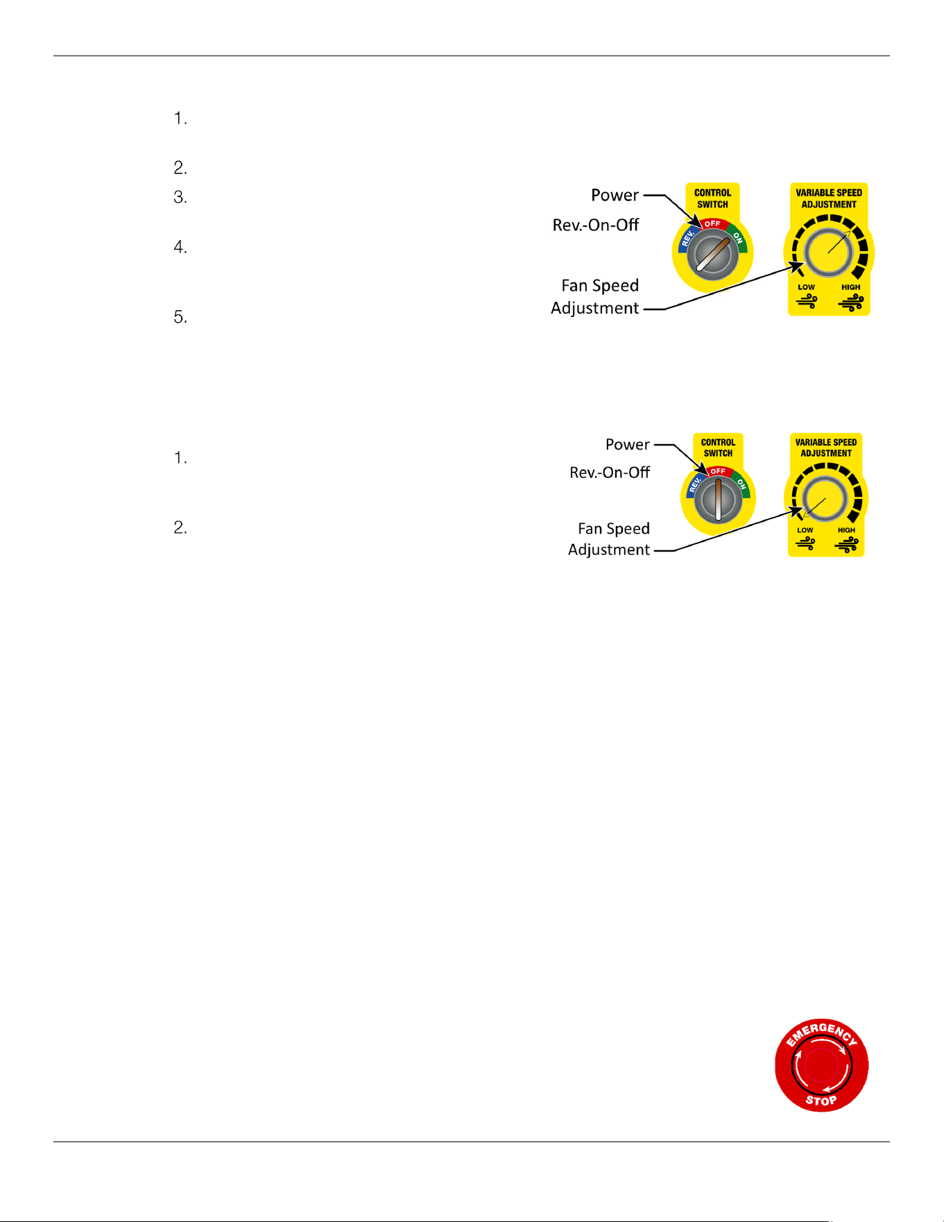
To operate the Cool Boss HVLS Fan:
Before starting the Cool Boss, verify that the Fan is undamaged, and no obstructions will
interfere or create a hazard with its operation.
Rotate the Speed Adjustment Knob to its low position.
Rotate the Control Switch to the On
position.
Rotate the Speed Adjustment until the
Fan is providing the amount of air circulation
desired.
Observe the Fan operation to verify that
there is no excessive shaking or wobbling and the Fan is operating safely in all respects.
⚠ WARNING Rotating Fan Blades! Keep all objects, hands, fingers, and loose clothing away from
the Fan when it is operating.
To shut down the Cool Boss HVLS Fan:
Rotate the Speed Adjustment knob to the
lowest setting and wait for the Fan to stop
rotating.
Rotate the Control Switch to the off
position.
To put the Cool Boss HVLS Fan into reverse:
⚠ WARNING Always allow the HVLS Fan to come to a complete stop before attempting to
reverse the Fan’s direction of rotation. It is not good practice to reverse direction
on any electric motor without first stopping the rotation. The VFD will likely go into
an error condition and may be damaged. In addition, the motor will draw much
more electrical current to reverse the direction of rotation creating heat in the
motor’s windings leading to a breakdown in the winding insulation. This will shorten
the Fan’s useful life.
1. Allow the Fan rotation to stop before proceeding.
2. Rotate the Speed Adjustment Knob to its lowest setting.
3. Rotate the Control Switch to the REV. position.
4. Rotate the Speed adjustment knob until the Fan is providing the amount of air circulation
desired.
5. Shutting down the fan is identical to the shut down instructions already described above.
To use the Emergency Stop
:
Pushing the Emergency Stop button will immediately remove power from the Controller and the
Fan Motor. All Fan functions are locked out until the Emergency Stop button is released. Pushing
the Emergency Stop will not immediately stop the fan blade motion. The blades will slow
gradually as energy is lost to drag and friction.
To release the Emergency stop
:
1. Rotate the
Control Switch
to the off position and the
Speed Adjustment
to the lowest-speed position.
Cool Boss Industrial HVLS Fan
34
P/N 5900279 — May 2023 — Rev. A2
2. Rotate the
Emergency Stop
button clockwise in the direction of the arrows printed on the
button. The button will pop out and the Fan may be operated normally.
Negative Ion Air Purifier Operation
The Cool Boss CB-20HVLS and CB-24HVLS Ionizer utilizes a high-voltage electrode to ionize the
surrounding air. The HVLS Fan forces air to move around an electrode generating negative ions
(anions). Anions are effective in removing particulates from the air.
To use the Ionizer function
:
1. Rotate the Fan Control Switch to the on position and adjust to the desired speed.
2.
Rotate the Ionizer Switch on the Control Panel to the
On position.
To shut down the Ionizer function
:
1. Rotate the Ionizer Switch to the Off position to shut down
the Ion generator.
Cool Boss Industrial HVLS Fan
35
P/N 5900279 — May 2023 — Rev. A2
Maintenance
⚠ DANGER Before servicing, cleaning, or maintenance, disconnect the unit at the service panel
and lock the service disconnecting means to prevent power from being switched
on accidentally. When the service disconnecting means cannot be locked, securely
fasten a prominent warning device, such as a tag, to the service panel.
⚠ DANGER After removing power from the Fan, even if the main Fan Motor is
disconnected, hazardous voltage may be present on the circuit
terminals. Verify terminals are safe with a Voltmeter before beginning work. For
your safety, do not begin work on the wiring until the voltage drops to a safe level.
Repairing or installing wiring when residual voltage is present may cause personal
injury, sparking or a short circuit.
⚠ DANGER Any electrical work must be accomplished by a licensed electrician in accordance
with all national, state, and local electrical codes.
⚠ WARNING Do not change any of the operating parameters on the Variable Frequency Drive
(VFD). This HVLS Fan is configured at the factory and unauthorized changes to the
VFD parameters may cause damage that is not covered under warranty.
⚠ WARNING Do not use this Fan with damaged or missing components!
⚠ WARNING Rotating Fan Blades can cause severe injury! Keep hands and loose clothing clear!
To maintain the Cool Boss HVLS:
• Daily Operation
.
Visually confirm the Fan is rotating clockwise when viewed from the ground.
• Daily Operation
.
Visually confirm the running condition of the Fan. No excessive rocking or swaying
should be present. If the Fan is swaying, immediately stop the Fan and inspect for loose fasteners or
guy wire supports.
• Daily Operation
.
No excessive noise should be created by the Fan. Immediately stop the Fan if
excessive or unusual noises are heard. Inspect the Fan and tag as inoperative until maintenance
personnel can determine the problem.
• Annually
. Inspect and v
erify fasteners are tight and in good condition.
• Annually. Inspect the Fan Blades and Tails for cracks or other damage and tighten to secure, if
loose.
• Annually. Inspect the Guy Wires and their mountings for wear. Repair/replace as required.
• Annually. Inspect labels. Replace any worn or illegible labels.
⚠ WARNING Do not spray the HVLS Fan with water. The electronics are not sealed. Water can
damage the motor and/or other parts of the electrical system.
⚠ WARNING
Do not operate your HVLS Fan if you find maintenance issues; instead, remove it from
service. Assistance with your HVLS Fan is available from your dealer, by calling Cool
Boss at (805) 933-9970, or by emailing
. You may also
contact Cool Boss for parts replacement (please have the serial number and model
number of your unit available).

Cool Boss Industrial HVLS Fan 36 P/N 5900279 — May 2023 — Rev. A2
To store the Cool Boss HVLS Fan:
If the Cool Boss Fan motor drive/controller is stored in a no-charge condition for more than 3 months,
the ambient storage temperature should be no higher than 30°C. Storage longer than one year is not
recommended, it could result in the degradation of the internal electrolytic capacitors.
Assistance with your Cool Boss is available from your dealer, by calling Cool Boss at
parts replacement (please have the serial number and model number of your unit available).
Cool Boss Industrial HVLS Fan
37
P/N 5900279 — May 2023 — Rev. A2
Troubleshooting
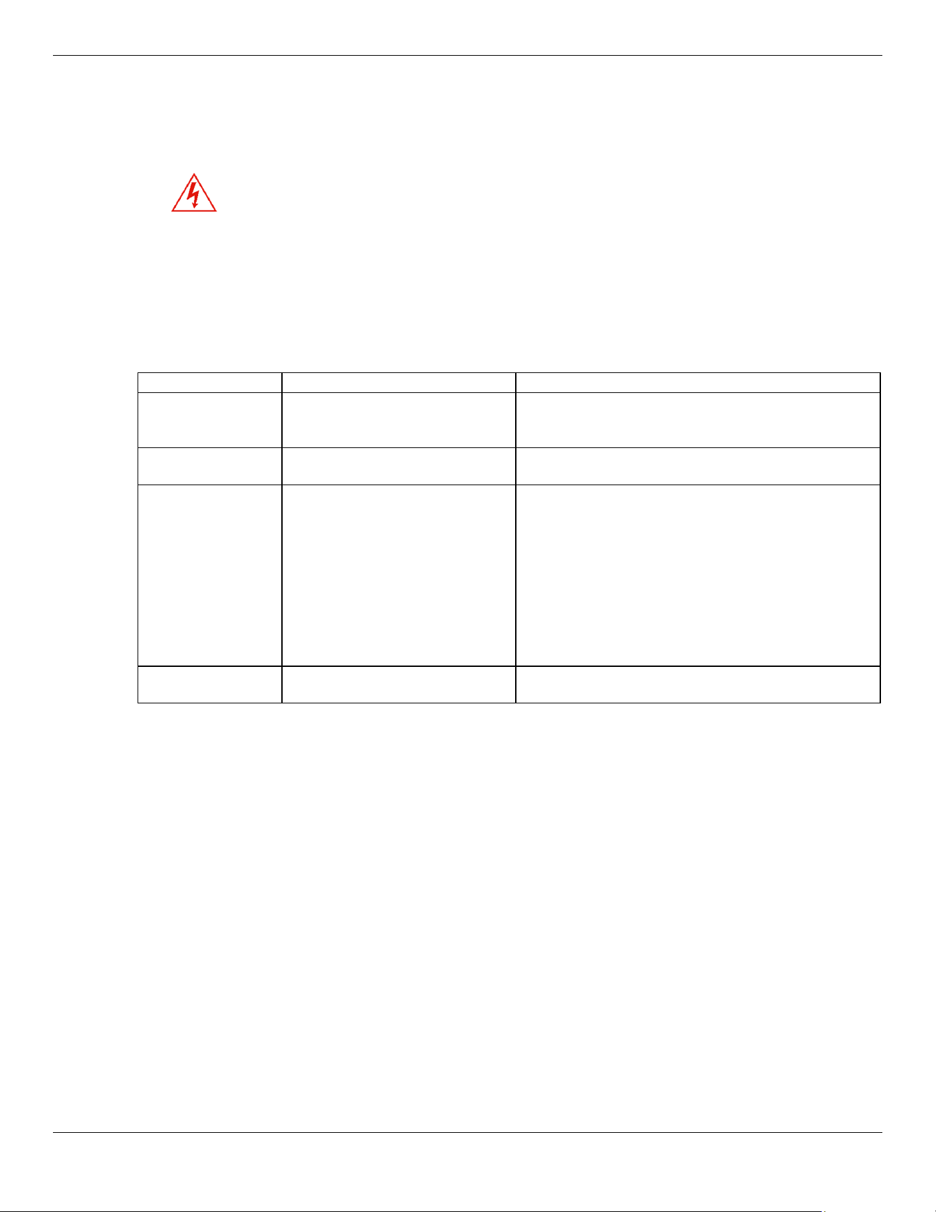
⚠ DANGER After removing power from the Fan, even if the main Fan Motor is
disconnected, hazardous voltage may be present on the circuit
terminals. Verify terminals are safe with a Voltmeter before beginning work. For
your safety, do not begin work on the wiring until the voltage drops to a safe level.
Repairing or installing wiring when residual voltage is present may cause sparking,
severe injury, or death.
⚠ DANGER Any electrical work must be accomplished by a licensed electrician in accordance
with all national, state, and local electrical codes.
⚠ WARNING Only qualified persons are allowed to service the Fan Motor or its controller.
Issue Probable Cause Action to Take
Control Panel
inoperative.
No power.
Circuit Breaker open.
Panel component failure.
– Check the power supply.
– Reset the circuit breaker.
– Replace the Control.
Fan not working or
moving slowly.
Fan is blocked by debris.
Brown-out or low voltage.
– Check for mechanical blockage and remove.
– Correct voltage supply issue.
Fan is swaying
excessively.
Loose fasteners or Guy Wires
and/or their mounts. Bent or
damaged Blades. Obstructions
too close to the Fan Blades. Fan
may be out of level.
Inspect for loose or damaged fasteners and tighten
or replace as required – Verify the Fan is still Level
before operating.
Inspect Blades for impact damage or bends. If
Blades are damaged or bent, replace as required.
Do not attempt to bend the Blades back into shape.
Obstructions too close to the Fan will cause
disruption in air flow and may cause the Fan to sway
and may eventually cause damage, if allowed to
continue.
Fan makes unusual
sounds.
Worn or broken components
and fasteners. Damaged Blades.
Inspect for worn components and contact Cool
Boss for parts or service.
(805) 933-9970
⚠ WARNING For areas with frequent brownout conditions. Premature electrical
component and Motor failure due to excessive high or low voltage is not covered
under warranty. Verify that the facility can provide the required current and voltage
for the HVLS Fan. While voltage variations are common (±5%) both high and low
voltage episodes in excess of 15% to 20% can cause Electric Motor overheating
and premature Motor failure.
Low voltage will cause the Motor to draw more electrical current to deliver the same
amount of force to the Spindle. Excessive current overheats the Motor Windings,
eventually burning through the insulation and resulting in complete Motor failure.
High voltage episodes can cause premature failure of electrical and electronic
components due to overheating.
Variable Frequency Drive (VFD) Errors Codes
⚠ WARNING Do not change any of the operating parameters on the Variable Frequency Drive
(VFD). This HVLS Fan is configured at the factory and unauthorized changes to the
VFD parameters may cause damage that is not covered under warranty.
Cool Boss Industrial HVLS Fan 38 P/N 5900279 — May 2023 — Rev. A2
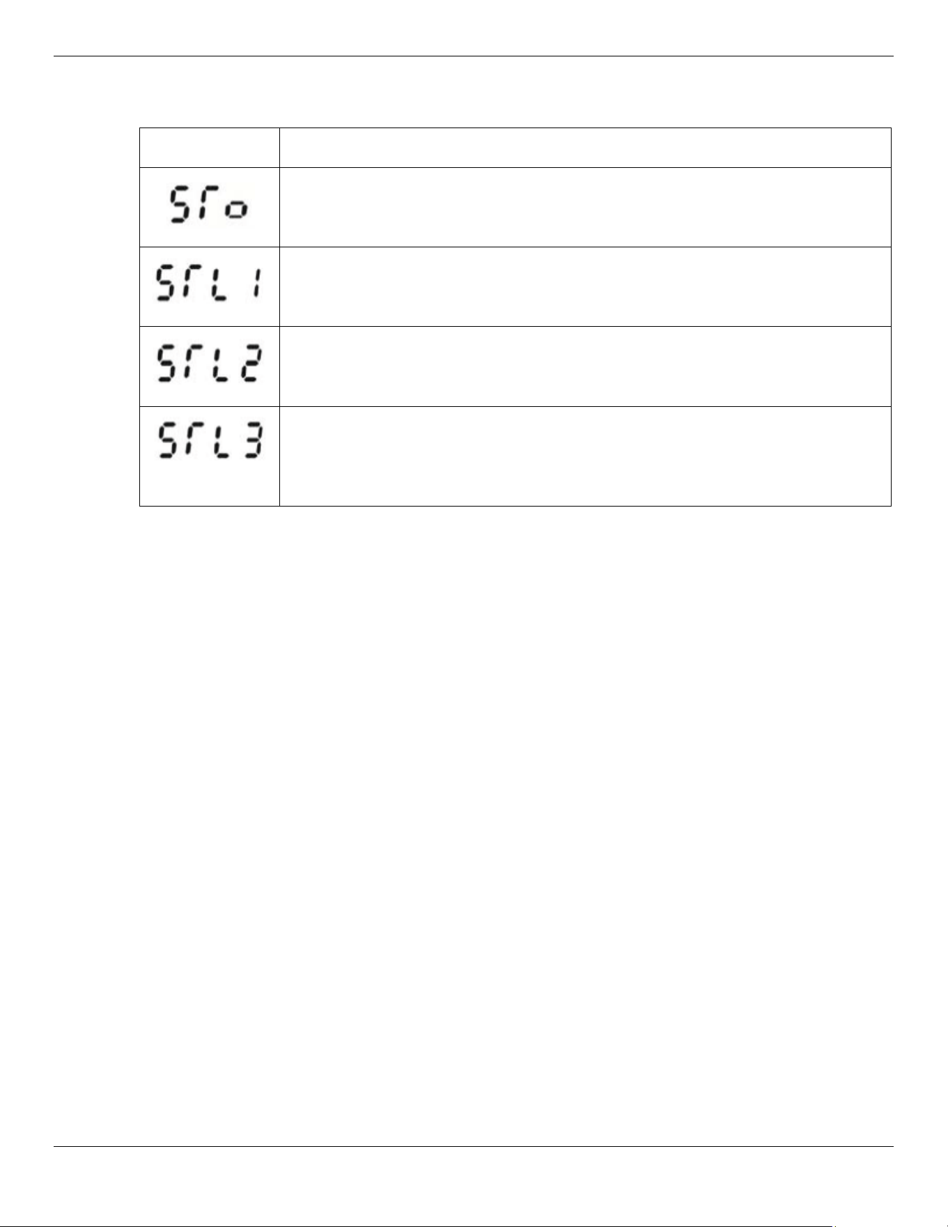
The Cool Boss HVLS Fan’s Variable Frequency Drive includes a self-test capability and will display fault
codes if a problem is detected.
Error Code Description
Safe-Torque off
Engage emergency off button and then cycle power back on.
Contact Cool Boss if fault persists.
Channel 1 (S1 - DCM) Safety Loop Error detected.
Engage emergency off button and then cycle power back on.
Contact Cool Boss if fault persists.
Channel 2 (S2 - DCM) Safety Loop Error
Engage emergency off button and then cycle power back on.
Contact Cool Boss if fault persists.
S1 - DCM and S2 - DCM internal Loop error detected.
Verify Power wiring is correct. Engage emergency off button and then cycle
power back on.
Contact Cool Boss if fault persists.
Assistance with your Cool Boss is available from your dealer, by calling Cool Boss at (805) 933-
replacement (please have the serial number and model number of your unit available).
Cool Boss Industrial HVLS Fan
39
P/N 5900279 — May 2023 — Rev. A2
Wiring Diagram
Schematic CB-11HVLS and CB-16HVLS
Cool Boss Industrial HVLS Fan
40
P/N 5900279 — May 2023 — Rev. A2
Illustrated Control Box Wiring Diagram CB-11HVLS and CB-16HVLS
Not drawn to scale. Components removed for clarity.
HVLS Control Box Dimensions
Height 15.75 in / 400 mm
Width 12 in. / 305 mm
Depth 8 in. / 203 mm
Cool Boss Industrial HVLS Fan
41
P/N 5900279 — May 2023 — Rev. A2
Illustrated Fan Motor Wiring Diagram CB-11HVLS and CB-16HVLS
Fan Motor Bottom View
Not drawn to scale. Components removed for clarity.
Cool Boss Industrial HVLS Fan
42
P/N 5900279 — May 2023 — Rev. A2
Schematic CB-20HVLS and CB-24HVLS
Cool Boss Industrial HVLS Fan
43
P/N 5900279 — May 2023 — Rev. A2
Illustrated Control Box Wiring Diagram CB-20HVLS and CB-24HVLS
Not drawn to scale. Components removed for clarity.
HVLS Control Box Dimensions
Height 15.75 in / 400 mm
Width 12 in. / 305 mm
Depth 8 in. / 203 mm
Cool Boss Industrial HVLS Fan
44
P/N 5900279 — May 2023 — Rev. A2
Illustrated Fan Motor Wiring Diagram CB-20HVLS and CB-24HVLS
Fan Motor Bottom View
Not drawn to scale. Components removed for clarity.
Cool Boss Industrial HVLS Fan
45
P/N 5900279 — May 2023 — Rev. A2
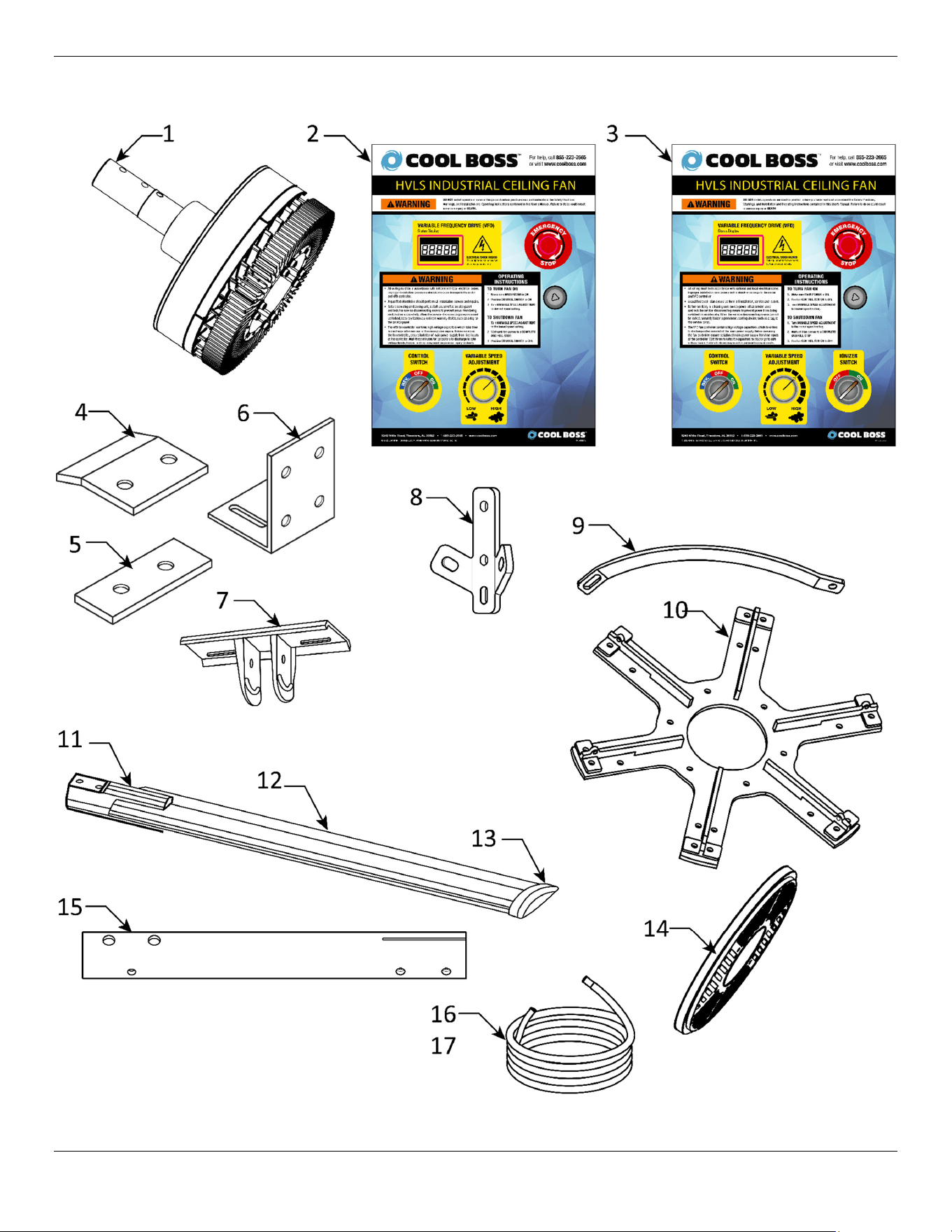
Parts Diagram
Cool Boss Industrial HVLS Fan 46 P/N 5900279 — May 2023 — Rev. A2
Specify Model and Serial Number when ordering spare/replacement parts.
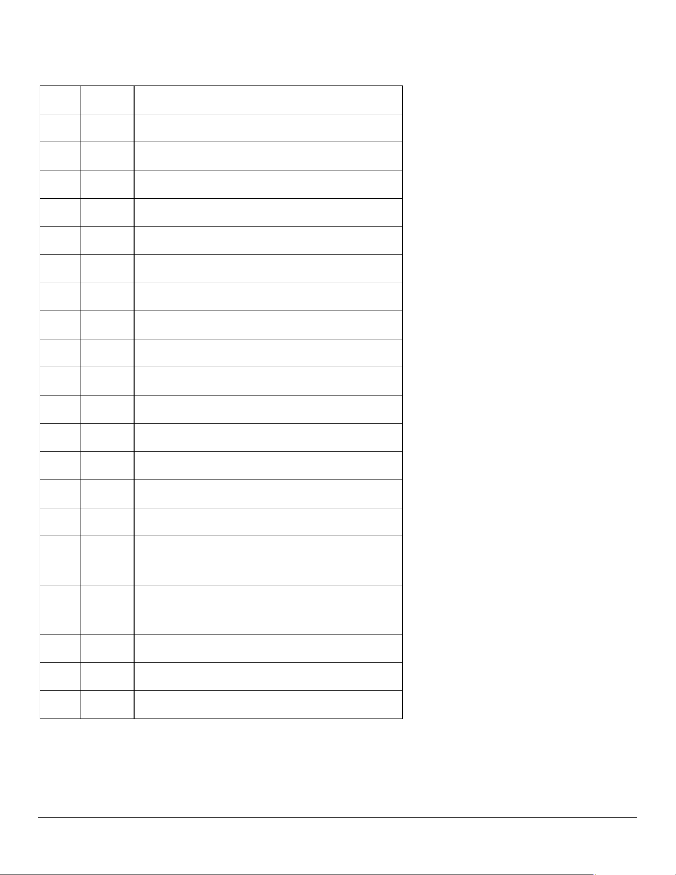
Item Qty. Description
1 1 Fan Motor
2 1 Fan Control CB11HVLS & CB-16HVLS Only
3 1 Fan Control CB20HVLS & CB24HVLS Only
4 2 Clamp
5 2 Spacer
6 2 L Bracket
7 1 Hanging Plate
8 2 Protection Ring
9 5/6 Arc Plate
10 1 Blade Connector Bracket
11 5/6 Blade Clip
12 5/6 Blade
13 5/6 Blade Tail
14 1 Cover
15 1 Down Rod
16
80 ft. /
25m
4-Conductor Control Cable
CB11HVLS & CB16HVLS Only
17
80 ft. /
25m
6-Conductor Control Cable
CB20HVLS & CB24HVLS Only
18 Set Fasteners (Not pictured above)
19 5/6 Rubber Pad (Not pictured above)
20 As Req. Guy Wire (Not pictured above)
Cool Boss Industrial HVLS Fan
47
P/N 5900279 — May 2023 — Rev. A2
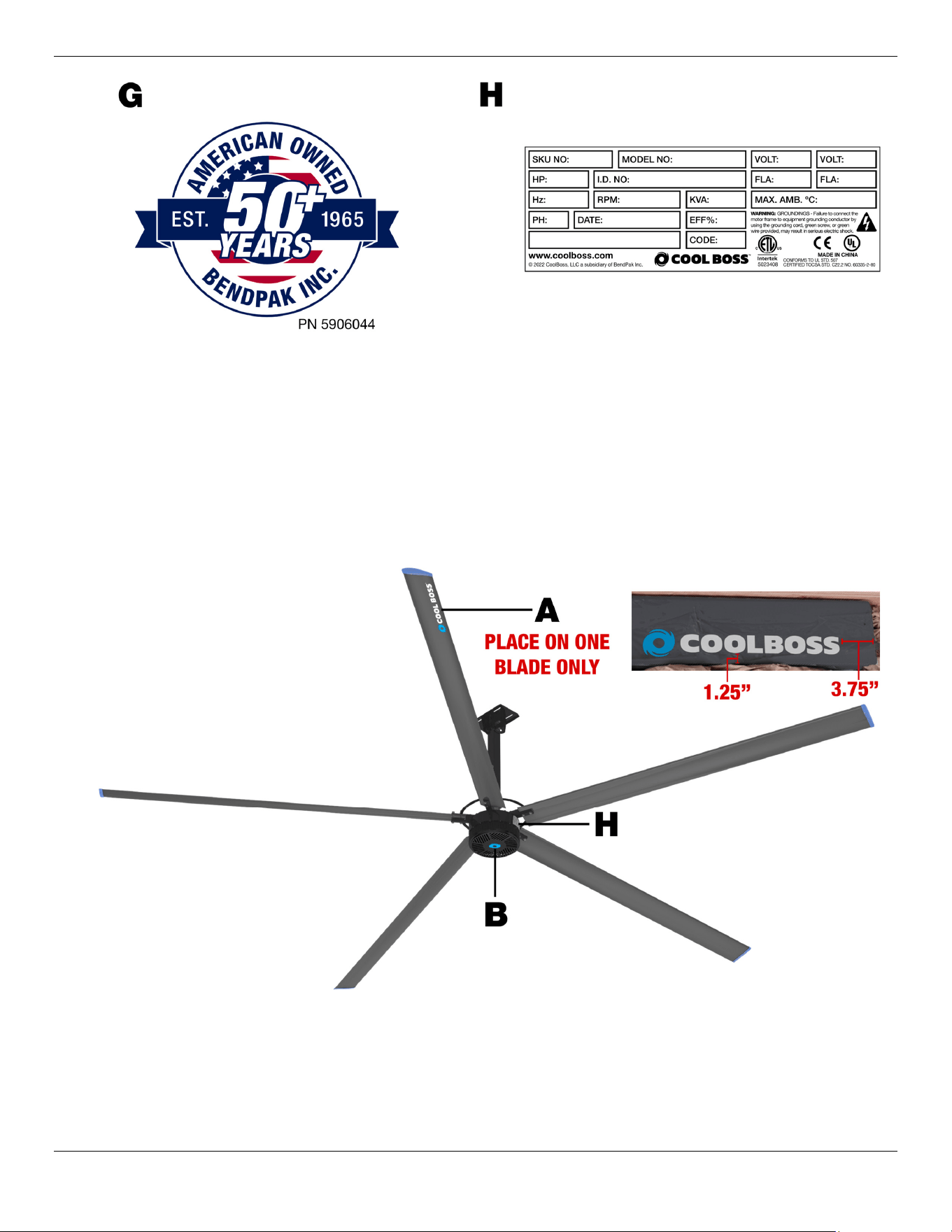
Labels
Cool Boss HVLS Industrial Ceiling Fan
48
P/N 5900279 — May 2023 — Rev. A2
Cool Boss HVLS Industrial Ceiling Fan 49 P/N 5900279 — May 2023 — Rev. A2
Maintenance Log
Cool Boss HVLS Industrial Ceiling Fan 50 P/N 5900279 — May 2023 — Rev. A2
Maintenance Log
Cool Boss HVLS Industrial Ceiling Fan 51 P/N 5900279 — May 2023 — Rev. A2
Maintenance Log

5240 Willis Rd.
Theodore, AL 36582 USA
coolboss.com
© 2023 BendPak Inc. All rights reserved.