IMPORTANT
READ THESE INSTRUCTIONS CAREFULLY BEFORE BEGINNING THE INSTALLATION. PROPER INSTALLA-
TION WILL PROVIDE SAFE AND EFFICIENT SERVICE, AND AVOID NEEDLESS EXPENSE NOT COVERED BY
THE WARRANTY. READ THE PRODUCT WARRANTY CONTAINED IN THIS MANUAL AND REMEMBER TO
FILL OUT AND RETURN TO THE MANUFACTURER ALL RELEVANT WARRANTY CARDS AND
CERTIFICATES. SHOULD YOU HAVE ANY QUESTIONS, PLEASE CONTACT YOUR LOCAL DEALER OR
REFER TO THE GETTING SERVICE FOR YOUR WATER HEATER SECTION OF THIS MANUAL.
SAVE THIS MANUAL FOR FUTURE REFERENCES.
COMMERCIAL ELECTRIC WATER HEATER, FLEXIBLE
OWNER’S MANUAL
INSTALLATION AND OPERATING INSTRUCTIONS
•
DO NOT
open the electrical junction box or the element
access panel before the power to the water heater is
turned
“OFF”.
•
DO NOT ATTEMPT
to repair or replace any of the
electrical components installed on the water heater
before the power to the water heater is turned “
OFF
”.
•
DO NOT USE
the water heater on a voltage other than
that specified on the water heater rating plate.
•
DO NOT CONNECT
the power supply wiring to
anywhere other than the power distribution block in elec-
trical junction box of the water heater.
•
DO NOT TURN ON
the power to the water heater unless
it is completely filled with water.
•
DO NOT DRAIN
the water heater unless the power to the
water heater has been turned “
OFF
”.
•
DO NOT STORE
or use gasoline or other flammable
vapours and liquids in the vicinity of this or any other
appliance.
WHAT TO DO IF YOU SMELL SMOKE
• Immediately turn “OFF” the power to the water heater.
• If after turning “OFF” the power the smoke continues,
call your local fire department.
• When the smoke has stopped, call a qualified service
technician to identify and repair the problem.
For your records, write the model and serial number here:
Model # ____________________________________
Serial # ____________________________________
GI-IM066En-0725
54000080
© 2025 A. O. Smith Enterprises Ltd. Printed in Canada
105-108-112 Models
DANGER
WARNING
CAUTION
AVERTISSEMENT
ATTENTION
If the information in these instructions is not followed
exactly, a fire or explosion may result causing property
damage, personal injury, or death.
R
R
2
TABLE OF CONTENTS
Safety Information ................................ 2
Installation Instructions .......................... 3
Location ...................................... 3
Water Piping .................................. 4
Temperature & Pressure-Relief Valve ........... 4
Pressure Build-up in a Water System ............ 5
Filling the Water Heater ........................ 5
Electrical Connections .......................... 8
Voltage ........................................9
Conversion Instructions ......................... 23
Field Conversions ............................ 23
Phase Conversions ............................23
Surface mount Thermostat .....................23
Wattage & Voltage Conversion for 208V,
240V & 480V Models ........................24
Wattage & Voltage Conversion for 600V Models..24
Operating Instructions .......................... 25
Installation Checklist .......................... 25
Starting the Water Heater ..................... 25
Start-up Procedure .............................26
Safety Controls ................................26
To reset the high limit switch .................... 26
Water Temperature Regulation ................ 26
To adjust the temperature on the thermostat .....26
General Maintenance ............................ 27
Element and Thermostat Replacement ..........27
Temperature and Pressure-Relief Valve ........ 27
Anodes ...................................... 27
Draining the Water Heater .................... 28
Vacation ..................................... 28
Getting Service for your Water Heater .......... 28
Replacement Parts ............................... 29
Troubleshooting Guide .......................... 34
Warranty ........................................ 36
SAFETY INFORMATION
Your safety and the safety of others is extremely important during the installation, operation, and servicing of this water heater. Many safety-
related messages have been provided in this manual and on your water heater. Always read and abide by all safety messages. These mes-
sages will point out the potential hazard, tell you how to reduce the risk of injury, and tell you what will happen if the instructions are not followed.
This is the safety alert symbol. This symbol alerts you to potential hazards that can kill or hurt you and others. All safety
messages will follow the safety alert symbol and either the word “DANGER” or “WARNING”.
Serious injury or death can occur if you do not
follow the instructions immediately.
Serious injury or death can occur if you do not
follow the instructions.
Before proceeding with the installation instructions:
1)
Inspect the water heater and its component parts for possible damage. Do not install or attempt to repair any damaged component
parts. If you detect any damage, contact the dealer where the water heater was purchased or the manufacturer listed on the war-
ranty card.
2)
Verify that the voltage being supplied corresponds to that which is marked on the water heater rating plate.
IMPORTANT
These instructions have been written as a guide for the proper installation and operation of your water heater, and the manufacturer
of this water heater will not accept any liability where these instructions have not been followed. However, for your safety and to avoid
damage caused by improper installation, this water heater must be installed by a Certified Licensed Professional, and meet all local
codes or, in the absence of local codes, CSA C22.1 Canadian Electrical Code, in Canada, and/or the National Electrical Code, ANSI/
NFPA 70, in the United States.
DANGER
WARNING
CAUTION
AVERTISSEMENT
ATTENTION
DO NOT use this water heater if any part has been under water. Immediately call a qualified service technician to inspect the water heater and to replace
any part of the control system which has been under water. Failure to follow this instruction can result in property damage, personal injury, or death.
3
Location
This water heater should be located as close as possible to an
adequate power supply and to the main use of hot water. This
location must not be subject to freezing temperatures. The water
heater should be positioned so that the electrical junction box,
element, and thermostat access panels can be opened for inspection,
adjustment, and servicing of the elements, thermostats and other
electrical components. The drain valve must also be accessible. The
water heater must be located close to a suitable free-flowing floor
drain. Where a floor drain is not adjacent to the water heater, a
suitable drain pan must be installed under the water heater (see
Figure 2). In Canada, according the National Plumbing Code, this
drain pan must be at least two (2) inches (5.1 cm) larger than the
diameter of the water heater, and at least three (3) inches (7.6 cm)
deep providing access to the drain valve. Always make sure to follow
local codes as they may be more rigorous. This pan must be piped to
a suitable drain to prevent damage to property in the event of a water
leak from the piping, the relief valve, or the water heater.
Sooner or later, all water heaters leak. The manufacturer,
based on national building codes has given the necessary
advice to prevent damage to the building. Under no
circumstances is the manufacturer to be held liable for
any water damage in connection with this water heater.
Suggested clearances for service purposes are a minimum of twelve
(12) inches (30.5 cm) from the top and thirty (30) inches (76.2 cm) in
front of the unit. Should this water heater be installed on carpeting, the
carpeting must be protected by a wood or metal panel beneath the
water heater. This panel must extend at least three (3) inches
(7.6 cm) beyond the width and depth of the water heater. Should the
water heater be installed in an alcove or closet, the entire floor area
must be covered by the panel.
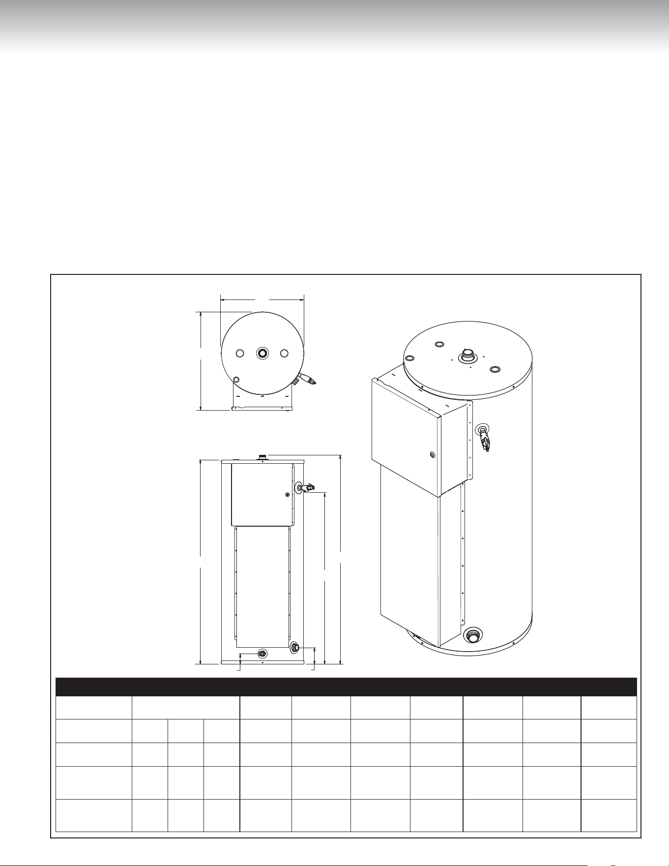
INSTALLATION INSTRUCTIONS
F
G
C
B
E
A D
SPECIFICATIONS
Models
Storage Capacity
Imp. gal. L Imp. gal.
A
Inches (cm)
B
Inches (cm)
C
Inches (cm)
D
Inches (cm)
E
Inches (cm)
F
Inches (cm)
G
Inches (cm)
105 49 184 41
3
1/8
(7.9) 40
1/4
(102) 49
1/8
(124.8) 4
7/8
(12.4) 50
5/8
(128.6) 26
1/4
(66.7) 22 (55.9)
108 74 279 61
3
1/8
(7.9) 51
3/8
(130.5) 59
5/8
(151.4) 4
7/8
(12.4) 62 (157.5) 28
1/4
(71.8) 24 (61)
112
2 & 4 elements
1122-1124
119 451 99
4
1/8
(10.5) 56
5/8
(143.8) 67
3/8
(171.1) 6
1/8
(15.6) 69
1/4
(175.9) 32
5/8
(82.9) 28
1/4
(71.8)
112
3, 6, & 9 elements
(1123-1126-1129)
119 451 99
5
1/8
(13) 58 (147.3) 69 (175.3) 7
1/8
(18.1) 70
1/8
(178.1) 33
3/4
(85.7) 29
1/2
(74.9)
Figure 1
4
INSTALLATION INSTRUCTIONS
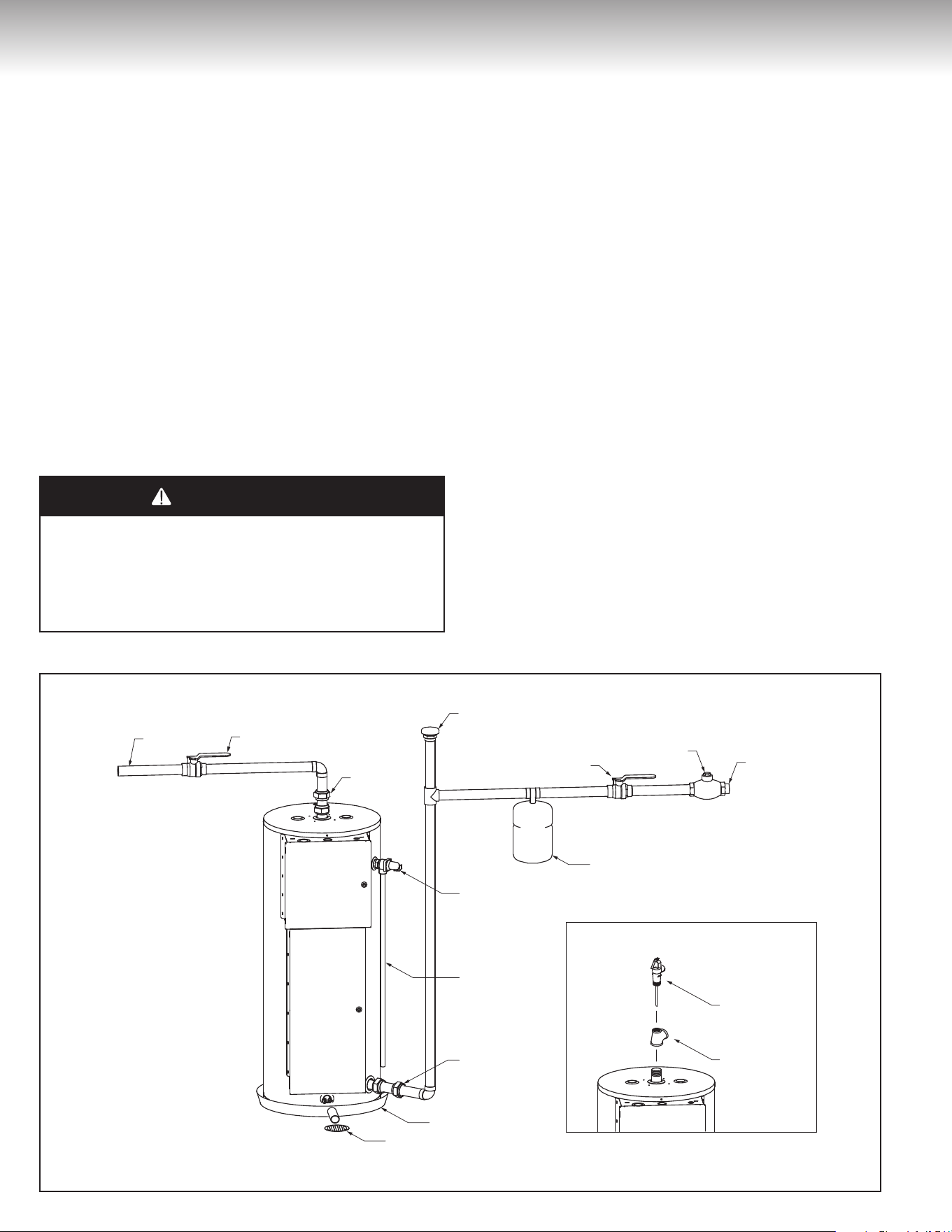
Water Piping
Refer to Figure 2 for a typical installation. Use of this layout should
provide a trouble-free installation for the life of the water heater. Refer to
Figures 3 to 9 for different installation configurations. Before making the
plumbing connections, locate the COLD water inlet and the HOT water
outlet, these fittings are both 1½” N.P.T. male thread. Female NPT
fittings must be used during the installation. Install a shut-off valves
close to the water heater in the hot and cold water lines. It is
recommended that unions be installed in the hot and cold water lines so
that the water heater can be easily disconnected, if servicing is required.
When assembling the hot and cold piping to the water heater, use
Teflon™ tape and wrap it clockwise around all the threads or a good
food grade of pipe joint compound, and ensure all fittings are tight. DO
NOT HEAT THESE FITTINGS when making welded connections to the
water heater. Solder the pipe to a threaded connection before screwing
it to the water heater fittings. It is imperative that open flame is not
applied to the inlet and outlet fittings, as heat will damage or destroy the
plastic lined fittings. This will result in premature failure of the
fittings, which is not covered by the warranty.
Temperature and Pressure-Relief Valve
DANGER
WARNING
CAUTION
AVERTISSEMENT
ATTENTION
DO NOT plug the temperature and pressure-relief valve or its
discharge line. DO NOT remove the relief valve. Make sure the
relief valve is properly sized for the water heater. If the relief valve
continuously discharges water, call a qualified service technician to
correct the problem. Failure to follow these instructions can result
in property damage, personal injury, or death.
In order to provide full protection against excess pressure and/or tem-
perature, a temperature & pressure-relief valve meeting the requirements
of the Standard Relief Valves and Automatic Gas Shut-Off Devices for
Hot Water Supply Systems, CSA 4.4, in Canada, and ANSI Z21.22, in
the United States is supplied with the water heater and MUST BE
installed by the installer. The relief valve should never be plugged or
removed from the opening marked for it on the water heater.
If this relief valve should need to be replaced, use only a new tempera-
ture and pressure-relief valve. Never install an old or existing relief valve,
as it may be damaged or inadequate for the working requirements of the
new water heater. This new relief valve must meet all local codes and
must have a maximum set pressure that does not exceed the hydro-
static working pressure of the water heater (150 psi = 1,035 kPa) and a
BTU/hr rating equal to or greater than the input rating, as shown on the
water heater rating plate. Never install another type of valve between the
relief valve and the water heater.
A discharge line must be installed into the relief valve. The discharge line:
• Must not be smaller than the outlet pipe size of the relief valve.
• Must not terminate less than six (6) inches (15.2 cm) and not more
than twelve (12) inches (30.5 cm) above a floor drain or drain pan con-
nected to an adequate free-flowing drain.
• Must not be restricted in any way. Do not thread, cap, or in any way
restrict the end of this outlet.
• Must be of a material capable of withstanding 210°F (99°C) without
distortion.
• Must be installed to allow complete drainage of the relief valve and
discharge line.
Vacuum Breaker
recommended
Thermal Expansion Tank
Temperature and
Pressure-Relief Valve
Temperature
and Pressure-Relief
Valve
Brass Tee
Overow Tube
Union
Drain Pan
Manual shut-o Valve
Check Valve
Drain
COLD WATER
INLET
HOT WATER
OUTLET
INSTALL AS PER LOCAL CODES
Union
Manual shut-o Valve
INSTALLER SELON LES CODES LOCAUX
Casse-vide
recommandé
Réservoir d'expansion thermique
Soupape de sûreté
température et
pression
Tuyau d'évacuation
Raccord
Bassin de rétention
Robinet d'arrêt manuel
Clapet
de retenue
Drain
ENTRÉE
D'EAU FROIDE
SORTIE
D'EAU CHAUDE
Raccord
Robinet d'arrêt manuel
Modèle 112 / 600V
à 63kW
112 / 600V at 63kW model only
Figure 2
5
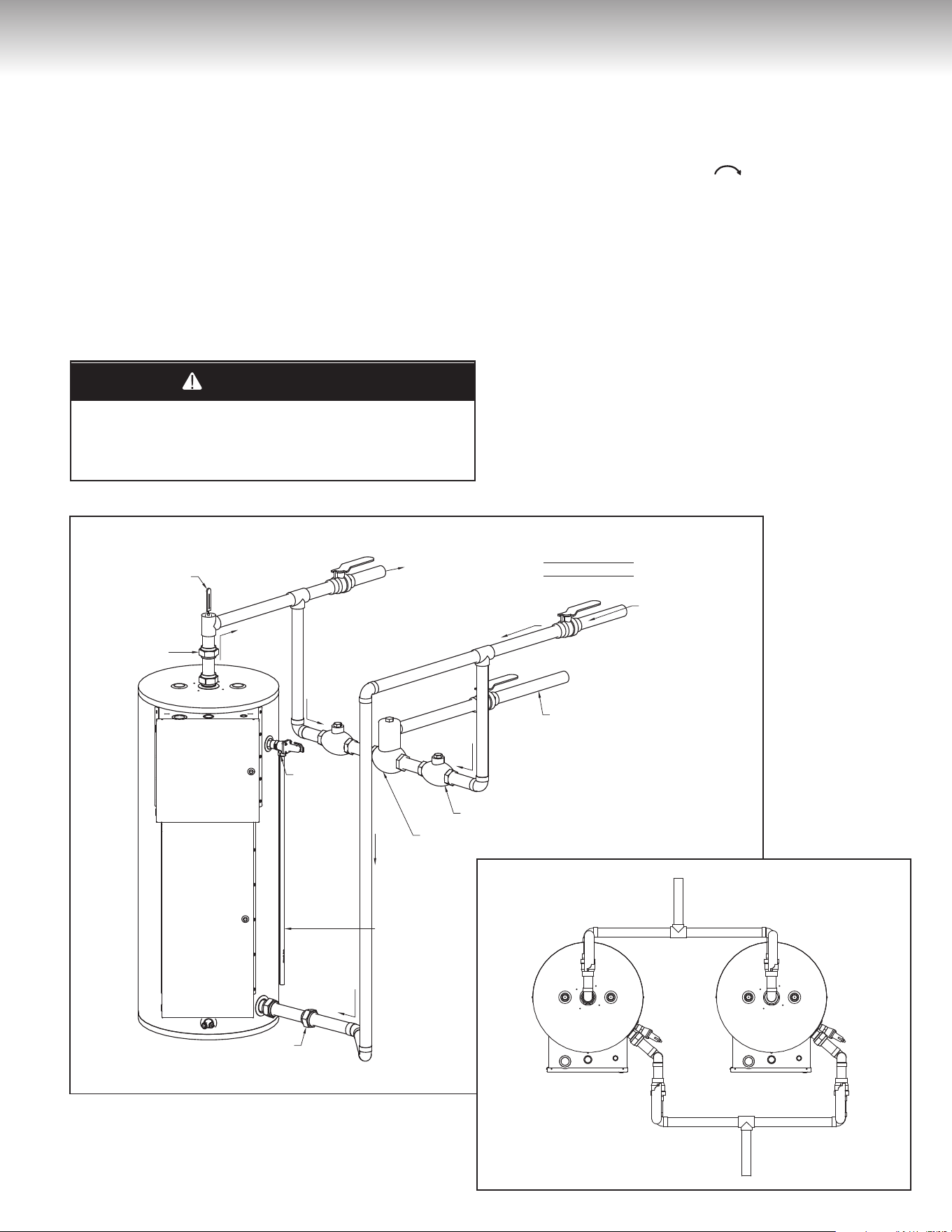
Thermometer
C heck Valve
Mixing Valve
TWO TEMPERATURE
WITH MIXING VALVE
HOT WATER OUTLET
Tempered Water Outlet
COLD WATER INLET
Overue Tube
Temperature
and
Pressure-
Relief Valve
Union
Union
Thermomètre
Clapet de retenue
Mitigeur
DEUX TEMPÉRATURES
AVEC MITIGEUR
SORTIE D'EAU CHAUDE
Sortie d'eau tempérée
ENTRÉE
D'EAU FROIDE
Tuyau d'évacuation
Soupape
de sûreté
Température
et pression
Raccord
Raccord
INSTALLATION INSTRUCTIONS
Figure 3
Pressure Build-up in a Water System
When the water heater operates, the heated water expands creating a
pressure build-up. This is a natural function and is one of the reasons
for installing a temperature and pressure-relief valve. If the cold water
supply line has a check valve, a backflow prevention device or pressure-
reducing valve, a suitable expansion tank (properly selected and
calibrated) must be installed to prevent any undue expansion. The water
distribution network must also be protected against water hammer by
means of prefabricated rams. In the absence of these protections, the
warranty is void (see Figure 2). An indication of pressure build-up is
frequent discharges of water from the relief valve. If the relief valve
discharges water on a continuous basis, it may indicate a malfunction of
the relief valve, and a qualified service technician must be called to have
the system checked, and the problem corrected.
Filling the Water Heater
DANGER
WARNING
CAUTION
AVERTISSEMENT
ATTENTION
NEVER operate the water heater unless it is completely filled with
water. Failure to follow this instruction can result in premature
failure of the water heater and its component parts that is not
covered by the warranty.
Check that all of the water piping connections have been made. To
fill the water heater:
1) Make sure that the water heater drain valve is closed by inserting
a flat-head screwdriver into the slot on the head of the drain valve
and turning the knob clockwise .
2) Open the cold water supply manual shut-off valve. This valve
must remain open, as long as the water heater is in use. Never
operate the water heater with the cold water supply manual shut-
off valve closed.
3) To make sure the water heater is completely filled with water,
open hot water faucets to let the air out of the water heater and
plumbing system. Leave the faucets open until a constant flow of
water is obtained.
4) Check all of the plumbing connections to make sure there are no
leaks.
TWO TANKS
IN PARALLEL
Hot Water
Outlet
Cold Water
Inlet
DEUX RÉSERVOIRS
EN PARALLÈLE
Sortie
d’eau chaude
Arrivée
d’eau froide
Figure 4
6
INSTALLATION INSTRUCTIONS
WATER
HEATER
1
WATER
HEATER
2
Thermomètre
Robinet régulateur de débit
Clapet de retenue
Clapet de retenue
Pompe circulatrice en bronze
Contrôle de température du conduit
CHAUFFE-EAU
1
CHAUFFE-EAU
2
SORTIE D'EAU CHAUDE
ENTRÉE D'EAU FROIDE
Réservoir d'expansion
thermique
NOTE : Les chaue-eau doivent être de taille identique
Raccord
Robinet d'arrêt manuel
Robinet d'arrêt manuel
Soupape
de température
et pression
Tuyau d'évacuation
Raccord
Raccord
Raccord
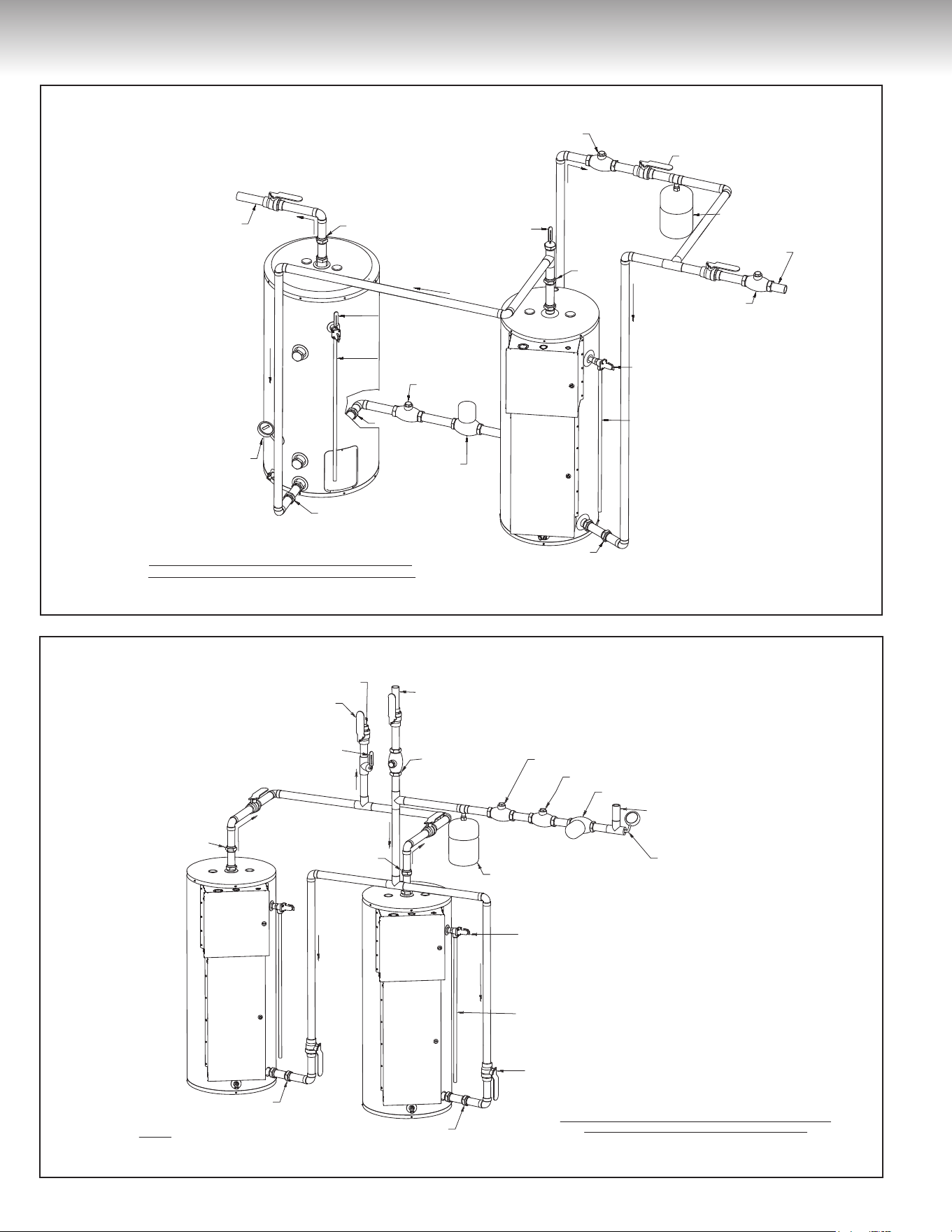
Thermometer
Flow regulating plug cock
Check Valve
All Bronze circulating Pump
Line temperature Control
TWO HEATERS WITH OR WITHOUT MIXING CIRCULATION,
WITH OR WITHOUT BUILDING RECIRCULATION
RETURN LINE FROM CIRCULATING LOOP
FOR STORED TEMPERATURE WATER
(IF USED)
HOT WATER OUTLET
COLD WATER INLET
Thermal Expansion Tank
NOTE: Must Be Identical Size Heater
Union
Manual Shut-o Valve
Manual Shut-o Valve
Safety Valve
Overue Tube
Union
Union
Union
Check Valve
DEUX CHAUFFE-EAU AVEC OU SANS CIRCULATION
MIXTE, AVEC OU SANS RECIRCULATION
CONDUIT DE RETOUR DE LA BOUCLE DE CIRCULATION
POUR L'EAU TEMPÉRÉE ENTREPOSÉE
(SI UTILISÉE)
Figure 6
TROIS CHAUFFE-EAU AVEC OU SANS CIRCULATION MIXTE,
AVEC OU SANS RECIRCULATION
Union
Union
Union
Union
Union
Check Valve
Clapet de
retenue
Check Valve
Thermometer
Thermometer
Thermal Expansion
Tank
All Bronze
Circulating Pump
Overue Tube
Overue Tube
Flow Regulating
Plug Cock
Shut-o Ball Valve
Cold Water
Supply
Tank Temperature
control170° Max.
Hot
Water
to Fixture
STORAGE
TANK
WATER HEATER
RÉSERVOIR
D’ENTREPOSAGE
CHAUFFE-EAU
Safety Valve
ONE TEMPERATURE ONE WATER HEATER & STORAGE TANK
FORCED CIRCULATION WITHOUT BUILDING RECIRCULATION
Pompe circulatrice
en bronze
Thermomètre
Thermomètre
Clapet
de retenue
Contrôle de température
de la cuve
SORTIE D'EAU CHAUDE
ENTRÉE D'EAU FROIDE
Robinet d'arrêt manuel
Soupape
de température
et pression
Tuyau d'évacuation
Tuyau d'évacuation
Robinet régulateur
de débit
Réservoir d'expansion thermique
Raccord
Raccord
Raccord
Raccord
Raccord
Figure 5
7
INSTALLATION INSTRUCTIONS
Réservoir d'expansion thermique
Clapet de retenue
Clapet de retenue
Robinet régulateur de débit
Pompe circulatrice en bronze
Thermomètre
Contrôle de température du conduit
ENTRÉE D'EAU FROIDE
CONDUIT DE RETOUR DE LA BOUCLE DE CIRCULATION
POUR L'EAU TEMPÉRÉE ENTREPOSÉE
(SI UTILISÉE)
SORTIE D'EAU CHAUDE
CHAUFFE-EAU
1
CHAUFFE-EAU
2
CHAUFFE-EAU
3
Robinet d'arrêt manuel
Raccord
Raccord
Tuyau d'évacuation
Soupape
de température
et pression
Robinet d'arrêt manuel
Raccord
Raccord
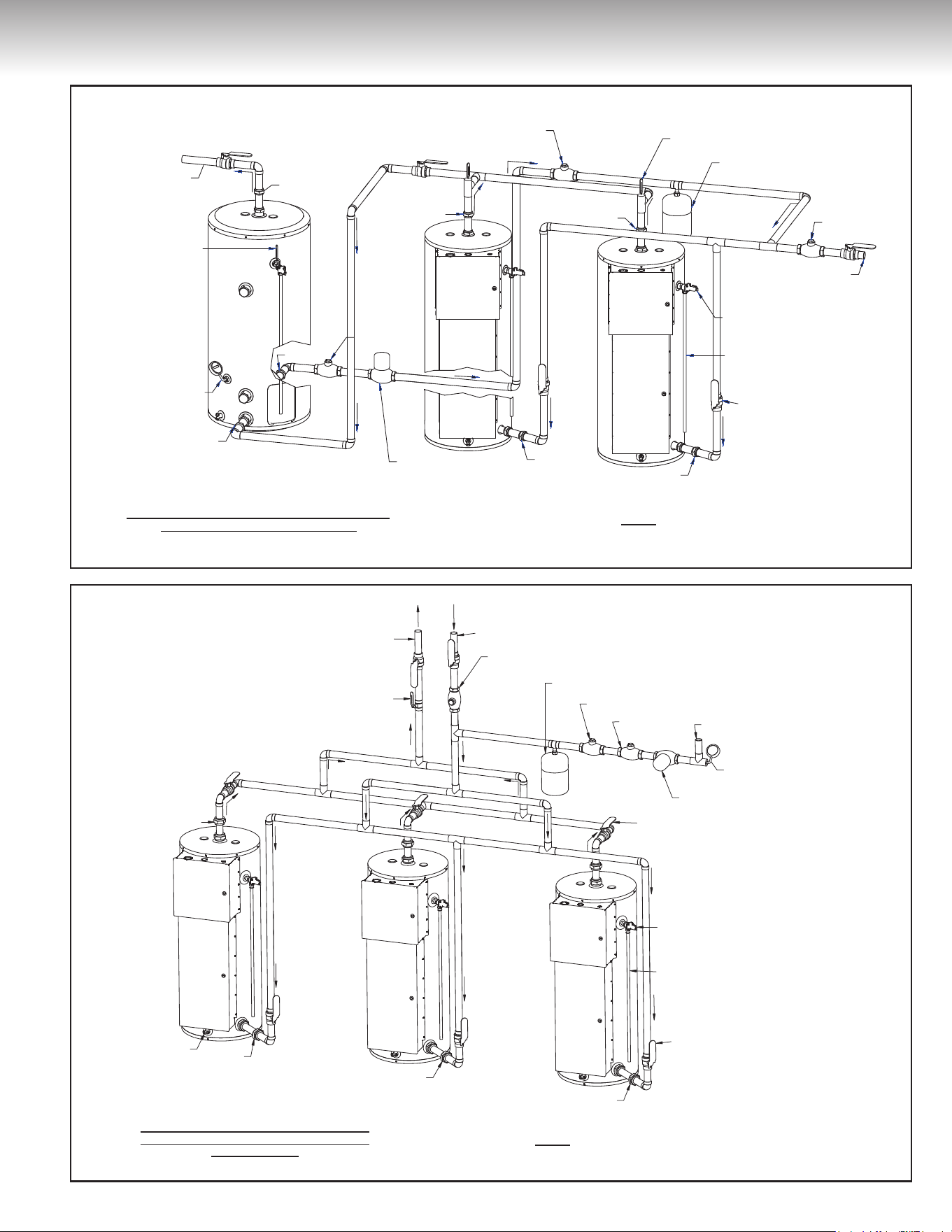
Overow Tube
Safety Valve
Union
Shut-o Ball Valve
Shut-o Ball Valve
Drain
Union
Union
Union
Line temperature Control
Thermal Expansion Tank
RETURN LINE FROM CIRCULATING LOOP
FOR STORED TEMPERATURE WATER
(IF USED)
All Bronze circulating Pump
Check Valve
Flow regulating plug cock
Check Valve
Thermometer
COLD WATER INLET
HOT WATER OUTLET
WATER
HEATER 1
WATER
HEATER 2
WATER
HEATER 3
THREE HEATERS WITH OR WITHOUT MIXING
CIRCULATION , WITH OR WITHOUT BUILDING
RECIRCULATION
NOTE :
Must Be Identical Size Water Heaters
Robinet
TROIS CHAUFFE-EAU AVEC OU SANS CIRCULATION
MIXTE, AVEC OU SANS RECIRCULATIONRECIRCULATION
NOTE :
Les chauffe-eau doivent être de taille et de puissance identiques
Figure 8
RÉSERVOIR
D'ENTREPOSAGE
Pompe circulatrice
en bronze
Robinet régulateur
de débit
Contrôle de température
de la cuve
Contrôle de température
de la cuve 170° Max.
SORTIE
D'EAU
CHAUDE
Thermomètre
Réservoir d'expansion
thermique
ALIMENTATION
EN EAU FROIDE
Thermomètre
Soupape
de température
et pression
Tuyau d'évacuation
Robinet d'arrêt manuel
Raccord
Raccord
Raccord
Raccord
Raccord
Raccord
Raccord
STORAGE
TANK
WATER
HEATER 2
WATER
HEATER 1
All Bronze
Circulating Pump
Flow Regulating
Plug Cock
Check Valve
Tank Temperature
control 170° Max.
Hot
Water
to Fixture
Thermometer
Thermal Expansion
Tank
Cold Water
Supply
Thermometer
TWO HEATERS WITH STORAGE TANK WITH OR
WITHOUT BUILDING CIRCULATION
Safety Valve
Overue Tube
Shut-o Ball Valve
Union
NOTE : Must Be Identical Size Heater
Union
Union
Union
Union
Union
Union
Check Valve
DEUX CHAUFFE-EAU AVEC OU SANS CIRCULATION MIXTE,
AVEC OU SANS RECIRCULATION
NOTE
: Les chauffe-eau doivent être de taille identique
CHAUFFE-EAU
1
CHAUFFE-EAU
2
Clapet de
retenue
Clapet de
retenue
Figure 7
8
INSTALLATION INSTRUCTIONS
Electrical Connections
DANGER
WARNING
CAUTION
AVERTISSEMENT
ATTENTION
This water heater uses an external electrical source for power. It
must be electrically grounded in accordance with all local codes or,
in the absence of local codes, CSA C22.1 Canadian Electrical
Code, in Canada, and/or the National Electrical Code, ANSI/NFPA
70, in the United States. Failure to properly ground this water
heater can result in property damage, personal injury, or death.
This water heater must be connected on a separate fuse branch
circuit. Check the water heater rating plate for the element wattage
and voltage and make sure that the power supply wiring and the fus-
ing or circuit breaker are the correct size for this water heater (see
Table 1). Verify that all of the wire connections on the elements and
thermostat have been installed correctly, are secure, and that none
of the wires are grounded, have split, or are broken (see WIRING
DIAGRAM, Figures 11 to 24). If any of the original wiring needs
replacing, use only TEW type wire that is approved for 221°F
(105°C) of the same size or greater. To hook up the water heater to
the power supply, connect the power supply wiring to the power
distribution block in the electrical junction box.
Flow Regulating
Plug Cock
Thermal Expansion
Tank
Thermometer
Check Valve
All Bronze
Circulating Pump
Tank Temperature
Control
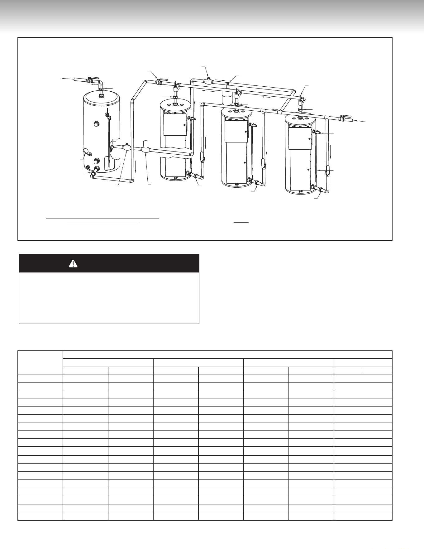
THREE WATER HEATERS WITH STORAGE TANK WITH OR
WITHOUT BUILDING CIRCULATION
STORAGE
TANK
WATER
HEATER 1
WATER
HEATER
2
WATER
HEATER
3
HOT WATER
OUTLET
COLD WATER
INLET
Temperature
and Pressure-
Relief Valve
Overue
Tube
Union
Manual
shut-O Valve
NOTE : Must Be Identical Power And Size Water Heaters
Union
Union
Union
Union
Union
Union
Union
Union
Robinet régulateur
de débit
Réservoir d'expansion
thermique
Thermomètre
Clapet de retenue
Pompe circulatrice
en bronze
Contrôle de température
de la cuve
TROIS CHAUFFE-EAU MUNIS D’UN RÉSERVOIR D’ENTREPOSAGE
AVEC OU SANS CIRCULATION
RÉSERVOIR
D'ENTREPOSAGE
CHAUFFE-EAU
1
CHAUFFE-EAU
2
CHAUFFE-EAU
3
SORTIE D'EAU CHAUDE
ALIMENTATION
EN EAU FROIDE
Soupape
de température
et pression
Tuyau
d'évacuation
Raccord
Robinet
d'arrêt manuel
NOTE : Les chaue-eau doivent être de taille identique
Raccord
Raccord
Raccord
Raccord
Raccord
Raccord
Raccord
Raccord
Figure 9
Total Input, kW
Voltage
208 Volts 240 Volts 480 Volts 600 Volts
1ph 3ph 1ph 3ph 1ph 3ph 3 ph 347V
3 14.4 — 12.5 — 6.3 — —
4.5 18.3 — 18.8 — 9.4 — —
5 24.0 — 20.8 — 10.4 — —
6 28.8 16.7 25.0 14.4 12.5 7.2 5.8
9 43.3 25.0 37.5 21.7 18.8 10.8 8.7
10 48.0 — 41.6 — 20.8 — —
12 57.7 33.3 50.0 28.9 25.0 14.4 11.5
13.5 64.9 37.5 56.3 32.5 28.1 16.2 13.0
15 72.1 41.6 62.5 36.1 31.3 18.0 14.4
18 86.5 50.0 75.0 43.3 37.5 21.7 17.3
24 115.4 66.6 100.0 57.7 50.0 28.9 23.1
27 129.8 74.9 112.5 65.0 56.3 32.5 26.0
30 144.2 83.3 125.0 72.2 62.5 36.1 28.9
36 173.1 99.9 150.0 86.6 75.0 43.3 34.6
40.5 194.7 112.4 168.8 97.4 84.4 48.7 39.0
45 216.3 124.9 187.5 108.3 93.8 54.1 43.3
54 — — 255.0 129.9 112.5 65.0 52.0
63 — — — — — — 60.0
Table 1 — Total Full Load Current in Amperes
9
INSTALLATION INSTRUCTIONS
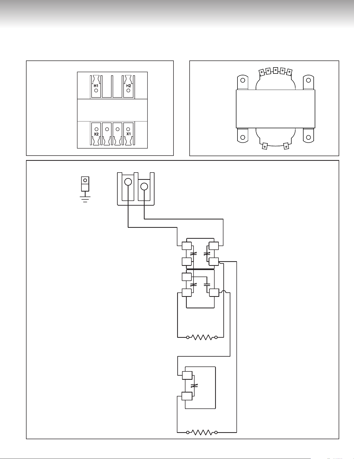
Voltage
When a control transformer is installed in the electrical junction box of
the water heater, make sure that the voltage on the connection of the
Transformer primary circuit is the same as the voltage on the rating
plate of the water heater.
480V 277V 240V 208V 0V
PRIMARY
X1 X2
0V 120V
480V 277V 240V 208V 0V
PRIMAIRE
X1 X2
0V 120V
Figure 10BFigure 10A
GROUND/
MISE À LA TERRE
HIGH LIMIT SWITCH/
INTERRUPTEUR
HAUTE TEMPÉRATURE
THERMOSTAT
THERMOSTAT
ELEMENT/
ÉLÉMENT
ELEMENT/
ÉLÉMENT
MISE À LA TERRE
INTERRUPTEUR
HAUTE TEMPÉRATURE
THERMOSTAT
THERMOSTAT
ÉLÉMENT
ÉLÉMENT
GROUND
HIGH LIMIT SWITCH
THERMOSTAT
THERMOSTAT
ELEMENT
ELEMENT
POWER DISTRIBUTION BLOCK POWER DISTRIBUTION BLOCK/BORNIER DE DISTRIBUTIONBORNIER DE DISTRIBUTION
GROUND/
MISE À LA TERRE
HIGH LIMIT SWITCH/
INTERRUPTEUR
HAUTE TEMPÉRATURE
THERMOSTAT
THERMOSTAT
ELEMENT/
ÉLÉMENT
ELEMENT/
ÉLÉMENT
MISE À LA TERRE
INTERRUPTEUR
HAUTE TEMPÉRATURE
THERMOSTAT
THERMOSTAT
ÉLÉMENT
ÉLÉMENT
POWER
DISTRIBUTION
BLOCK
GROUND
HIGH LIMIT SWITCH
THERMOSTAT
THERMOSTAT
ELEMENT
ELEMENT
POWER DISTRIBUTION BLOCK/BORNIER DE DISTRIBUTIONBORNIER
DE
DISTRIBUTION
RED/ROUGE
RED/ROUGE
RED/ROUGE
BLACK/NOIR
BLACK/NOIR
BLACK/NOIRBLACK/NOIR
Ancien Nom : Commer_Wiring_04 Nouveau Nom : DF-Comm-50-80-120G-2Ele
ROUGE
ROUGE
ROUGE
NOIR
NOIR
NOIRNOIR
Ancien Nom : Commer_Wiring_04 Nouveau Nom : DF-Comm-50-80-120G-2Ele
RED
RED
RED
BLACK
BLACK
BLACKBLACK
Ancien Nom : Commer_Wiring_04 Nouveau Nom : DF-Comm-50-80-120G-2Ele
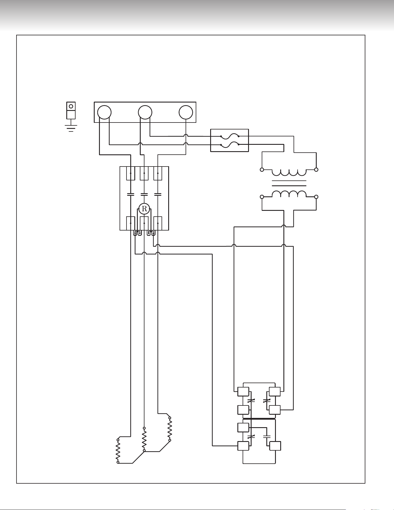
Figure 11
208 Volts / 240 Volts / 480 Volts
(single phase)
Wiring diagram
for commercial electric water heater
models 105, 108 & 112
with 2 elements
PRIMARY
600V
240V
PRIMAIRE
600V
240V
10
INSTALLATION INSTRUCTIONS
GROUND
HIGH LIMIT SWITCH
THERMOSTAT
ELEMENT
THERMOSTAT
ELEMENT
THERMOSTAT
ELEMENT
THERMOSTAT
ELEMENT
HIGH LIMIT SWITCH
MISE À LA TERRE
INTERRUPTEUR
HAUTE TEMPÉRATURE
INTERRUPTEUR
HAUTE TEMPÉRATURE
THERMOSTAT THERMOSTAT
ÉLÉMENTÉLÉMENT
ÉLÉMENTÉLÉMENT
THERMOSTATTHERMOSTAT
THERMOSTAT THERMOSTAT
THERMOSTATTHERMOSTAT
GROUND/
MISE À LA TERRE
HIGH LIMIT SWITCH/
INTERRUPTEUR
HAUTE TEMPÉRATURE
HIGH LIMIT SWITCH/
INTERRUPTEUR
HAUTE TEMPÉRATURE
ELEMENT/ÉLÉMENT ELEMENT/ÉLÉMENT
ELEMENT/ÉLÉMENT ELEMENT/ÉLÉMENT
POWER DISTRIBUTION BLOCK
GROUND
HIGH LIMIT SWITCH
THERMOSTAT
ELEMENT
THERMOSTAT
ELEMENT
THERMOSTAT
ELEMENT
THERMOSTAT
ELEMENT
HIGH LIMIT SWITCH
MISE À LA TERRE
INTERRUPTEUR
HAUTE TEMPÉRATURE
INTERRUPTEUR
HAUTE TEMPÉRATURE
THERMOSTAT THERMOSTAT
ÉLÉMENTÉLÉMENT
ÉLÉMENTÉLÉMENT
THERMOSTATTHERMOSTAT
GROUND/
MISE À LA TERRE
HIGH LIMIT SWITCH/
INTERRUPTEUR
HAUTE TEMPÉRATURE
HIGH LIMIT SWITCH/
INTERRUPTEUR
HAUTE TEMPÉRATURE
THERMOSTAT THERMOSTAT
ELEMENT/ÉLÉMENT ELEMENT/ÉLÉMENT
ELEMENT/ÉLÉMENT ELEMENT/ÉLÉMENT
THERMOSTATTHERMOSTAT
Ancien Nom : Commer_Wiring_05 Nouveau Nom : DF-Comm-50-80-120G-4EleAncien Nom : Commer_Wiring_05 Nouveau Nom : DF-Comm-50-80-120G-4EleAncien Nom : Commer_Wiring_05 Nouveau Nom : DF-Comm-50-80-120G-4Ele
POWER DISTRIBUTION BLOCK/BORNIER DE DISTRIBUTIONBORNIER DE DISTRIBUTION
POWER DISTRIBUTION BLOCK POWER DISTRIBUTION BLOCK/BORNIER DE DISTRIBUTIONBORNIER DE DISTRIBUTION
RED
RED
RED
RED
RED
RED
BLACK
BLACK
BLACK
BLACK
BLACK
BLACK
NOIR
NOIR
NOIR
NOIR
BLACK/NOIR
BLACK/NOIR
BLACK/NOIR
BLACK/NOIR
BLACK
BLACK
ROUGE
ROUGE
ROUGE
ROUGE
ROUGE
ROUGE
NOIR
NOIR NOIR
NOIR
RED/ROUGE
RED/ROUGE
RED/ROUGE
RED/ROUGE
RED/ROUGE
RED/ROUGE
BLACK/NOIR
BLACK/NOIR BLACK/NOIR
BLACK/NOIR
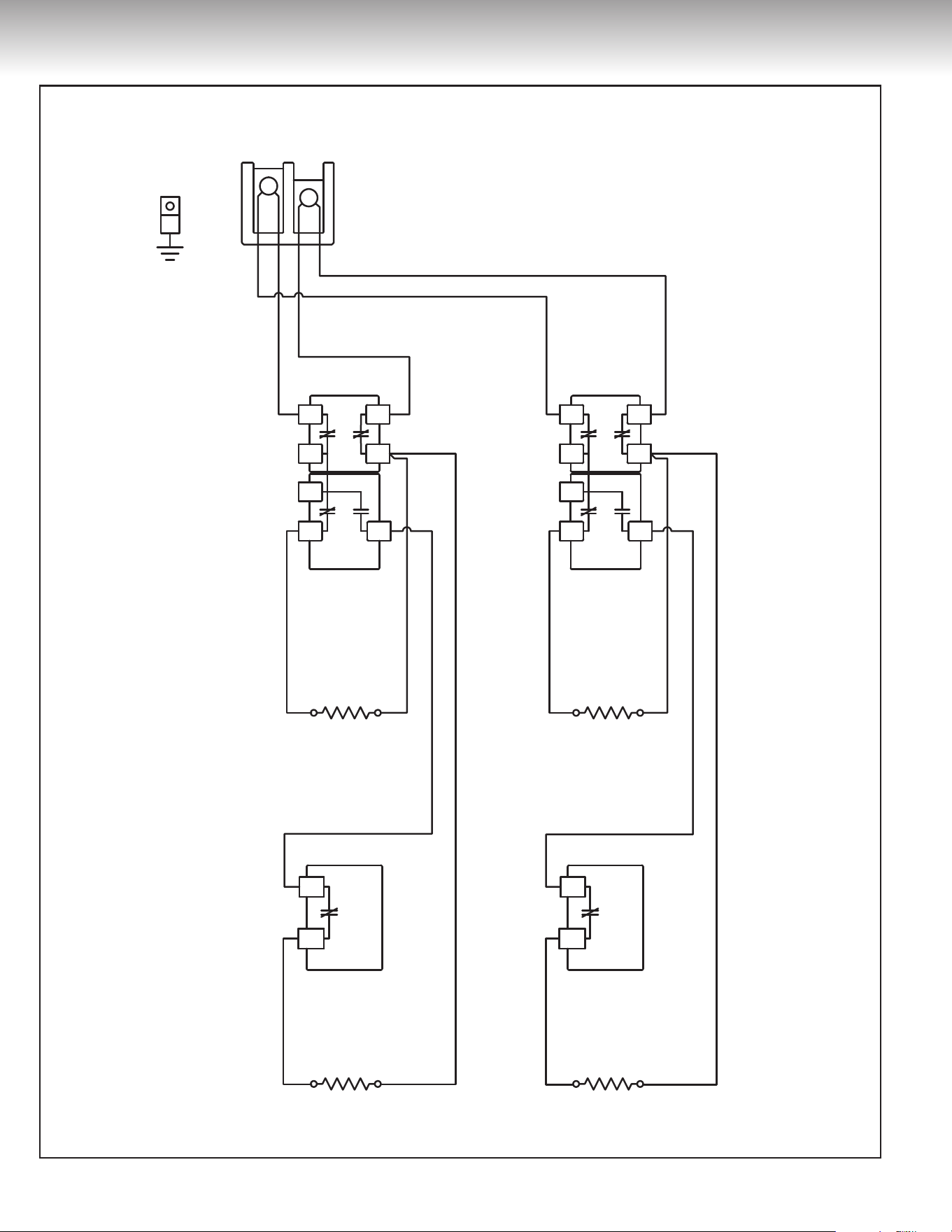
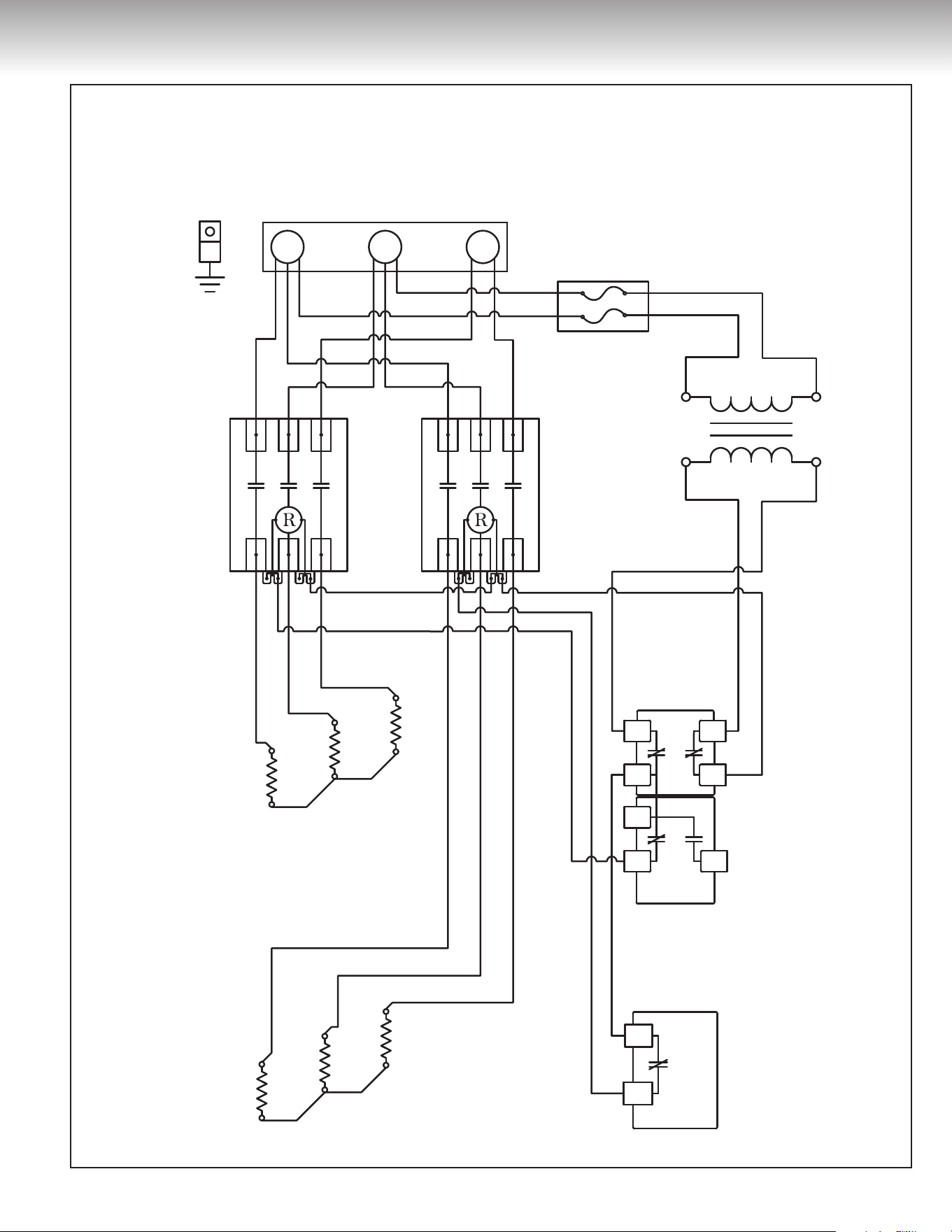
Figure 12
208 Volts / 240 Volts / 480 Volts
(single phase)
Wiring diagram
for commercial electric water heater
models 105, 108 & 112
with 4 elements
11
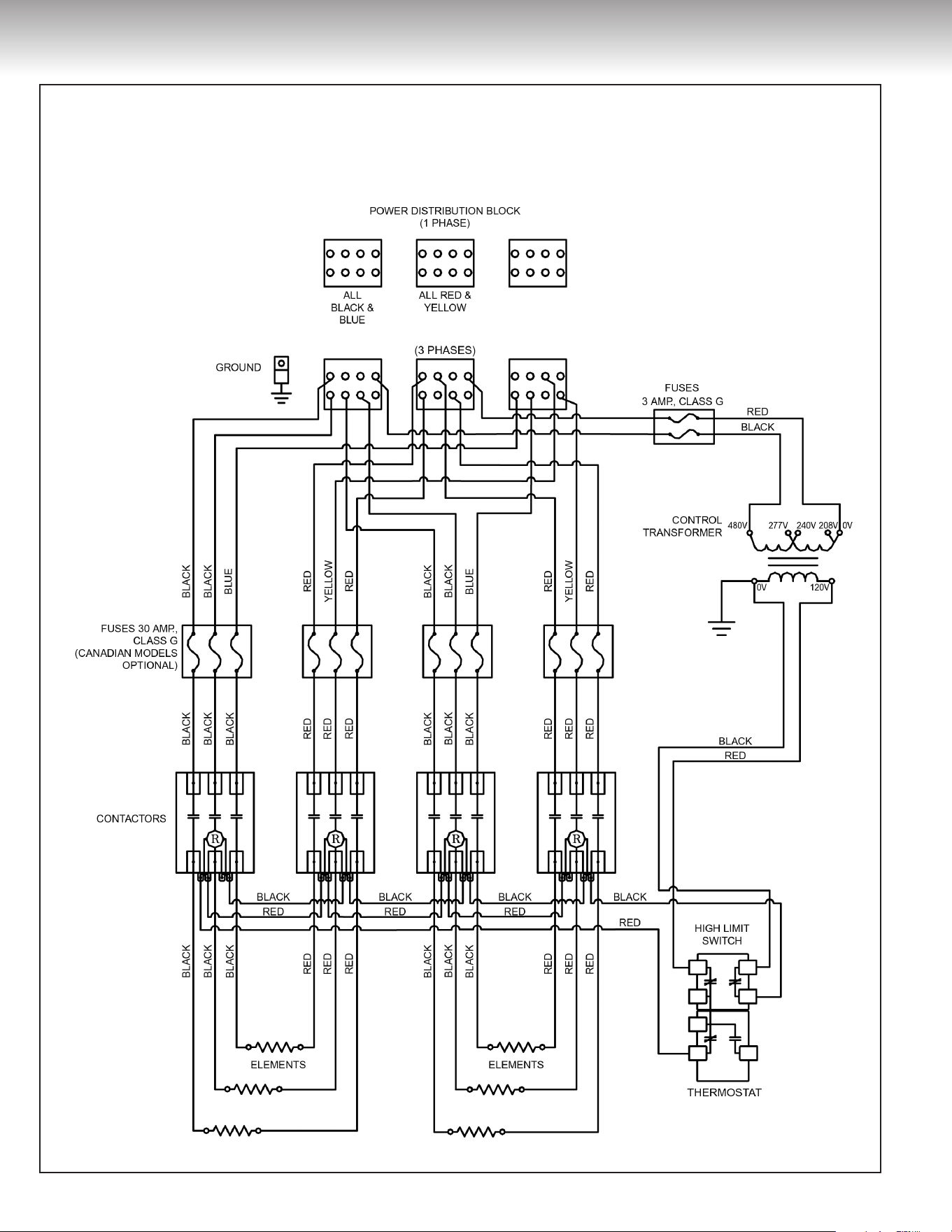
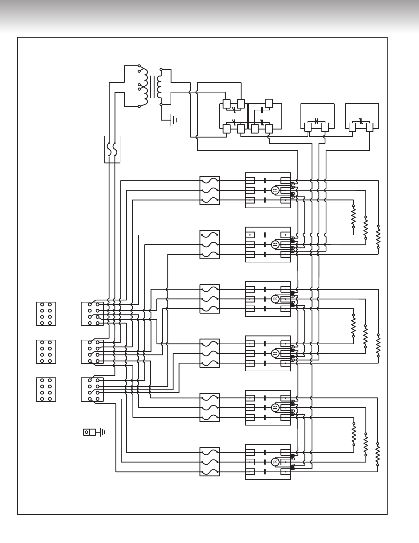
POWER DISTRIBUTION BLOCK (1 PHASE)
ALL BLACK & BLUE
ALL RED & YELLOW
(3 PHASES)
GROUND
HIGH LIMIT SWITCH
THERMOSTAT
ELEMENTS
CONTACTORS
FUSES 30 AMP., CLASS G
(CANADIAN MODELS OPTIONAL)
HIGH LIMIT SWITCH
THERMOSTAT
TO CONTACTOR
TO CONTACTOR
FROM CURRENT
TRANSFORMER
BORNIER DE DISTRIBUTION (1 PHASE)
TOUS LES
NOIRS ET BLEUS
TOUS
LES ROUGES ET JAUNES
(3 PHASES)
MISE À LA TERRE
INTERRUPTEUR
HAUTE TEMPÉRATURE
THERMOSTAT
ÉLÉMENTS
CONTACTEURS
FUSES 30 AMP., CATÉGORIE G
(MODÈLES CANADIENS OPTIONNELS)
INTERRUPTEUR
HAUTE TEMPÉRATURE
THERMOSTAT
VERS CONTACTEUR
VERS CONTACTEUR
DU TRANSFORMATEUR
DE CONTRÔLE
POWER DISTRIBUTION BLOCK/BORNIER DE DISTRIBUTION
(1 PHASE)
ALL BLACK &
BLUE/TOUS LES
NOIRS ET BLEUS
ALL RED &
YELLOW/TOUS
LES ROUGES ET JAUNES
(3 PHASES)
GROUND/
MISE À LA TERRE
FUSES/FUSIBLES
3 AMP., CLASS/CATÉGORIE G
CONTROL
TRANSFORMER/
TRANSFORMATEUR
DE CONTRÔLE
HIGH LIMIT SWITCH/
INTERRUPTEUR
HAUTE TEMPÉRATURE
THERMOSTAT
ELEMENTS/
ÉLÉMENTS
CONTACTORS/
CONTACTEURS
FUSES/FUSIBLES
30 AMP., CLASS/CATÉGORIE G
(CANADIAN MODELS OPTIONAL)/
(MODÈLES CANADIENS OPTIONNELS)
HIGH LIMIT SWITCH/
INTERRUPTEUR
HAUTE TEMPÉRATURE
THERMOSTAT
TO CONTACTOR/
VERS CONTACTEUR
TO CONTACTOR/
VERS CONTACTEUR
FROM CURRENT
TRANSFORMER/
DU TRANSFORMATEUR
DE CONTRÔLE
ALTERNATIVE
THERMOSTAT-HIGH LIMIT
CONSTRUCTION
ALTERNATIVE DE
BRANCHEMENT DE
THERMOSTAT ET INTERRUPTEUR
HAUTE TEMPÉRATURE
ALTERNATIVE
THERMOSTAT-HIGH LIMIT
CONSTRUCTION/ALTERNATIVE
DE BRANCHEMENT DE
THERMOSTAT ET INTERRUPTEUR
HAUTE TEMPÉRATURE
480V
0V 120V
277V 240V 208V 0V
FUSES
3 AMP., CLASS G
CONTROL
TRANSFORMER
480V
0V 120V
277V 240V 208V 0V
FUSIBLES
3 AMP., CATÉGORIE G
TRANSFORMATEUR
DE CONTRÔLE
480V
0V 120V
277V 240V 208V 0V
POWER DISTRIBUTION BLOCK (1 PHASE)
ALL
BLACK & BLUE
ALL
RED & YELLOW
(3 PHASES)
GROUND
HIGH LIMIT SWITCH
THERMOSTAT
ELEMENTS
CONTACTORS
BORNIER DE DISTRIBUTION (1 PHASE)
TOUS LES
NOIRS ET BLEUS
TOUS
LES ROUGES ET JAUNES
(3 PHASES)
MISE À LA TERRE
INTERRUPTEUR
HAUTE TEMPÉRATURE
THERMOSTAT
ÉLÉMENTS
CONTACTEURS
POWER DISTRIBUTION BLOCK/BORNIER DE DISTRIBUTION
(1 PHASE)
ALL BLACK &
BLUE/TOUS LES
NOIRS ET BLEUS
ALL RED &
YELLOW/TOUS
LES ROUGES ET JAUNES
(3 PHASES)
GROUND/
MISE À LA TERRE
CONTROL
TRANSFORMER/
TRANSFORMATEUR
DE CONTRÔLE
480V
0V 120V
277V 240V 208V 0V
HIGH LIMIT SWITCH/
INTERRUPTEUR
HAUTE TEMPÉRATURE
THERMOSTAT
ELEMENTS/
ÉLÉMENTS
CONTACTORS/
CONTACTEURS
FUSES 30 AMP., CLASS G
(CANADIAN MODELS OPTIONAL)
FUSES 30 AMP., CATÉGORIE G
(MODÈLES CANADIENS OPTIONNELS)
FUSES/FUSIBLES
30 AMP., CLASS/CATÉGORIE G
(CANADIAN MODELS OPTIONAL)/
(MODÈLES CANADIENS OPTIONNELS)
FUSES/FUSIBLES
3 AMP., CLASS/CATÉGORIE G
CONTROL
TRANSFORMER
480V
0V 120V
277V 240V 208V 0V
FUSES
3 AMP., CLASS G
TRANSFORMATEUR
DE CONTRÔLE
480V
0V 120V
277V 240V 208V 0V
FUSIBLES
3 AMP., CATÉGORIE G
RED
BLACK
BLACK
BLUE
BLACK
BLACK
BLACK
RED
RED
YELLOW
BLUE
BLUE
BLACK
BLACK
RED
RED
RED
BLACK
RED
BLACK
BLACK
RED
RED
BLACK
RED
Ancien nom : Commer_50-80_03_Rev-B Nouveau Nom : DF-Comm-50-80-3Ele
ROUGE
NOIR
NOIR
BLEU
BLEU
NOIR
NOIR
NOIR
ROUGE
ROUGE
JAUNE
BLEU
NOIR
NOIR
ROUGE
ROUGE
NOIR
ROUGE
ROUGE
NOIR
NOIR
ROUGE
ROUGE
NOIR
ROUGE
Ancien nom : Commer_50-80_03_Rev-B Nouveau Nom : DF-Comm-50-80-3Ele
RED/ROUGE
RED/ROUGE
BLACK/NOIR
RED/ROUGE
BLACK/NOIR
BLACK/NOIR
RED
RED
BLACK
BLACK
ROUGE
ROUGE
NOIR
NOIR
BLACK/NOIR
BLUE/BLEU
BLUE/BLEU
BLACK/NOIR
BLACK/NOIR
BLACK/NOIR
RED/ROUGE
RED/ROUGE
YELLOW/JAUNE
BLUE/BLEU
BLACK/NOIR
BLACK/NOIR
RED/ROUGE
RED/ROUGE
RED/ROUGE
BLACK/NOIR
RED/ROUGE
BLACK/NOIR
BLACK/NOIR
RED/ROUGE
RED/ROUGE
BLACK/NOIR
RED/ROUGE
Ancien nom : Commer_50-80_03_Rev-B Nouveau Nom : DF-Comm-50-80-3Ele
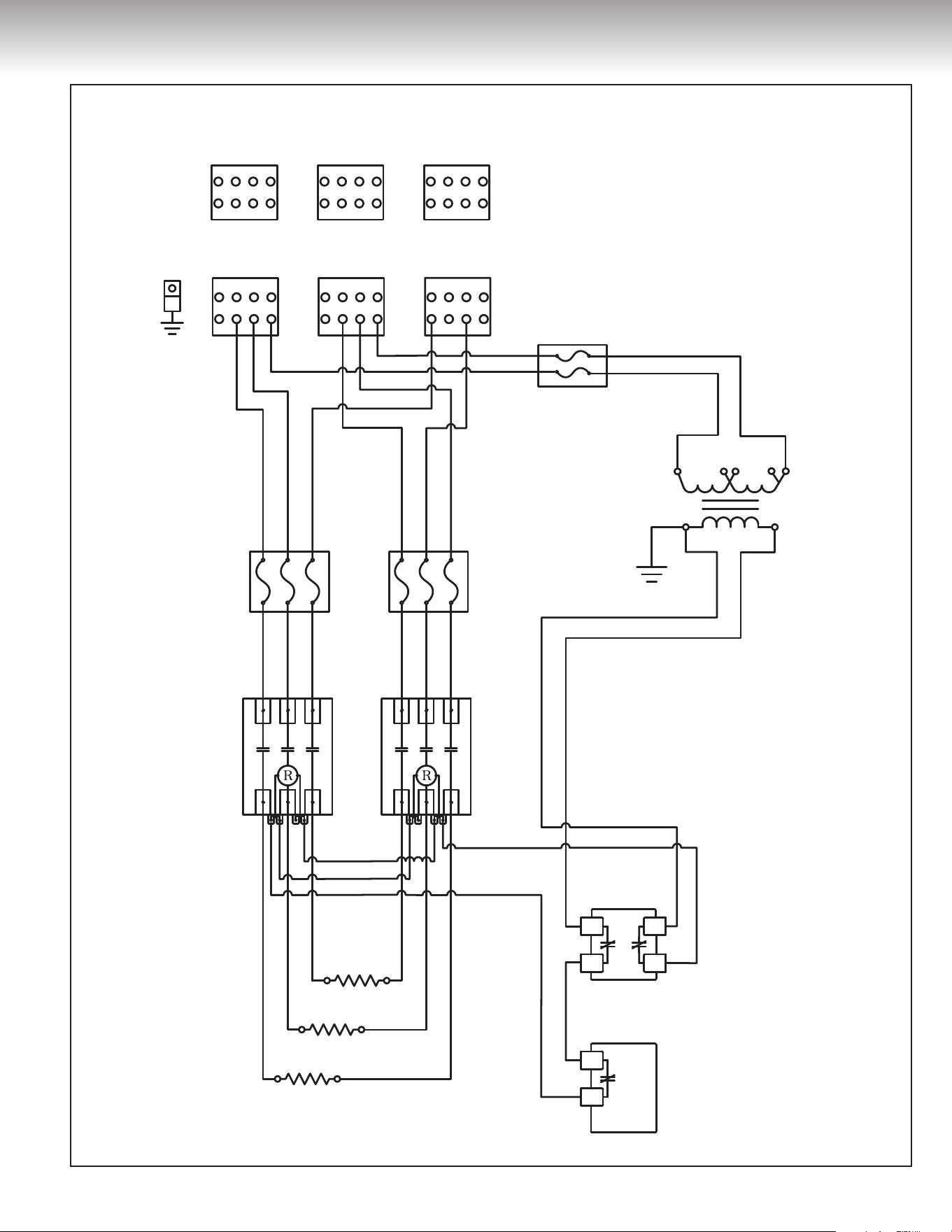
INSTALLATION INSTRUCTIONS
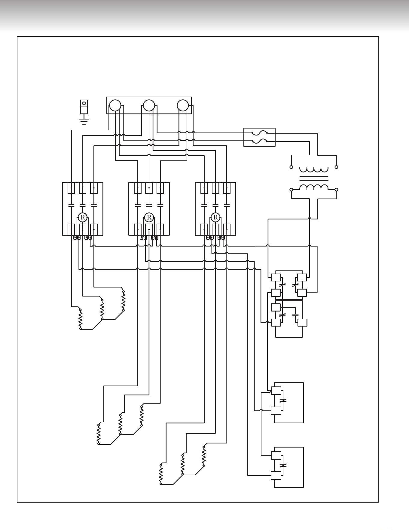
Figure 13
208 Volts / 240 Volts / 480 Volts
Wiring diagram
for commercial electric water heater
models 105, 108
with 3 elements
12
INSTALLATION INSTRUCTIONS
Figure 14
208 Volts / 240 Volts / 480 Volts
Wiring diagram
for commercial electric
water heater
models 105, 108
with 6 elements
13
CONTACTORS
ELEMENTS ELEMENTS ELEMENTS
THERMOSTATTHERMOSTAT
HIGH LIMIT SWITCH
ALL BLACK &
BLUE
ALL RED &
YELLOW
(3 PHASES)
480V 277V 240V 208V 0V
0V 120V
GROUND
FUSES
3 AMP., CLASS G
FUSES 30 AMP., CLASS G
(CANADIAN MODELS OPTIONAL)
CONTROL
TRANSFORMER
POWER DISTRIBUTION BLOCK (1 PHASE)
RED
RED
BLACK
RED
BLACK
BLACK
RED
BLACK
RED
BLACK
RED
BLACK
RED
BLACK
RED
BLACK
RED
BLACK
BLACK
BLACK
RED
RED
YELLOW
RED
RED
YELLOW
RED
RED
YELLOW
BLUE
BLACK
BLACK
BLUE
BLACK
BLACK
BLUE
RED
RED
RED
BLACK
BLACK
BLACK
RED
RED
RED
BLACK
BLACK
BLACK
RED
RED
RED
BLACK
BLACK
BLACK
RED
RED
RED
BLACK
BLACK
BLACK
RED
RED
RED
BLACK
BLACK
BLACK
RED
RED
RED
BLACK
BLACK
BLACK
INSTALLATION INSTRUCTIONS
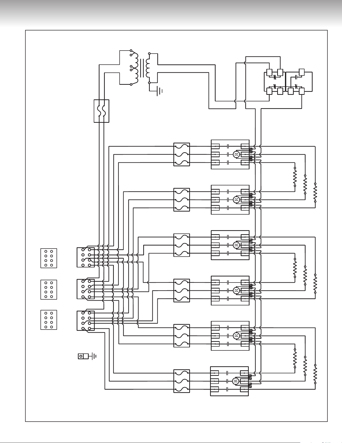
Figure 15
208 Volts / 240 Volts / 480 Volts
Wiring diagram
for commercial electric water heater
models 105, 108
with 9 elements
14
HIGH LIMIT SWITCH
THERMOSTAT
ELEMENTS
CONTACTORS
ALL
BLACK & BLUE
ALL
RED & YELLOW
(3 PHASES)
GROUND
INTERRUPTEUR
HAUTE TEMPÉRATURE
THERMOSTAT
ÉLÉMENTS
CONTACTEURS
TOUS LES NOIRS
ET BLEUS
TOUS LES
ROUGES ET JAUNES
(3 PHASES)
MISE À LA TERRE
HIGH LIMIT SWITCH/
INTERRUPTEUR
HAUTE TEMPÉRATURE
THERMOSTAT
ELEMENTS/
ÉLÉMENTS
CONTACTORS/
CONTACTEURS
FUSES/FUSIBLES
3 AMP., CLASS/CATÉGORIE G
ALL BLACK &
BLUE/TOUS LES NOIRS
ET BLEUS
ALL RED &
YELLOW/ TOUS LES
ROUGES ET JAUNES
(3 PHASES)
GROUND/
MISE À LA TERRE
120V
480V 277V 240V 208V 0V
0V
CONTROL
TRANSFORMER/
TRANSFORMATEUR
DE CONTRÔLE
FUSIBLES
3 AMP., CATÉGORIE G
120V
480V 277V 240V 208V 0V
0V
TRANSFORMATEUR
DE CONTRÔLE
FUSES
3 AMP., CLASS G
120V
480V 277V 240V 208V 0V
0V
CONTROL
TRANSFORMER
POWER DISTRIBUTION BLOCK (1 PHASE)
POWER DISTRIBUTION BLOCK/BORNIER DE DISTRIBUTION
(1 PHASE)
BORNIER DE DISTRIBUTION (1 PHASE)
FUSES 30 AMP., CLASS G
(CANADIAN MODELS OPTIONAL)
FUSIBLES
30 AMP., CATÉGORIE G
(MODÈLES CANADIENS OPTIONNELS)
FUSES/FUSIBLES
30 AMP., CLASS/CATÉGORIE G
(CANADIAN MODELS OPTIONAL)/
(MODÈLES CANADIENS OPTIONNELS)
HIGH LIMIT SWITCH
THERMOSTAT
ELEMENTS
CONTACTORS
ALL
BLACK & BLUE
ALL
RED & YELLOW
(3 PHASES)
GROUND
FUSES 30 AMP., CLASS G
(CANADIAN MODELS OPTIONAL)
INTERRUPTEUR
HAUTE TEMPÉRATURE
THERMOSTAT
ÉLÉMENTS
CONTACTEURS
TOUS LES NOIRS
ET BLEUS
TOUS LES
ROUGES ET JAUNES
(3 PHASES)
MISE À LA TERRE
FUSIBLES
30 AMP., CATÉGORIE G
(MODÈLES CANADIENS OPTIONNELS)
HIGH LIMIT SWITCH/
INTERRUPTEUR
HAUTE TEMPÉRATURE
THERMOSTAT
ELEMENTS/
ÉLÉMENTS
CONTACTORS/
CONTACTEURS
FUSES/FUSIBLES
3 AMP., CLASS/CATÉGORIE G
ALL BLACK &
BLUE/TOUS LES NOIRS
ET BLEUS
ALL RED &
YELLOW/ TOUS LES
ROUGES ET JAUNES
(3 PHASES)
GROUND/
MISE À LA TERRE
FUSES/FUSIBLES
30 AMP., CLASS/CATÉGORIE G
(CANADIAN MODELS OPTIONAL)/
(MODÈLES CANADIENS OPTIONNELS)
120V
480V 277V 240V 208V 0V
0V
CONTROL TRANSFORMER/
TRANSFORMATEUR
DE CONTRÔLE
FUSIBLES
3 AMP., CATÉGORIE G
120V
480V 277V 240V 208V 0V
0V
TRANSFORMATEUR
DE CONTRÔLE
FUSES
3 AMP., CLASS G
120V
480V 277V 240V 208V 0V
0V
CONTROL TRANSFORMER
POWER DISTRIBUTION BLOCK (1 PHASE)
POWER DISTRIBUTION BLOCK/BORNIER DE DISTRIBUTION
(1 PHASE)
BORNIER DE DISTRIBUTION (1 PHASE)
RED
RED
YELLOW
BLACK
RED
BLACK
BLACK
BLUE
RED
RED
BLACK
BLACK
RED
BLACK
RED
RED
BLACK
BLACK
RED
BLACK
BLUE
BLUE
BLACK BLACK
ROUGE
ROUGE
JAUNE
NOIR
ROUGE
NOIR
NOIR
BLEU
ROUGE
ROUGE
NOIR
NOIR
ROUGE
NOIR
ROUGE
ROUGE
NOIR
NOIR
ROUGE
NOIR
BLEU
BLEU
NOIR NOIR
Ancien nom : Commer_Wiring_03_Rev_B_2012-10-19 Nouveau nom : DF-Comm-120G3Ele
RED/ROUGE
RED/ROUGE
YELLOW/JAUNE
BLACK/NOIR
RED/ROUGE
BLACK/NOIR
RED/ROUGE
NOIR
ROUGE
NOIR
ROUGE
BLACK
RED
BLACK
RED
BLACK/NOIR
RED/ROUGE
BLACK/NOIR
BLACK/NOIR
BLUE/BLEU
RED/ROUGE
RED/ROUGE
BLACK/NOIR
BLACK/NOIR
RED/ROUGE
BLACK/NOIR
RED/ROUGE
RED/ROUGE
BLACK/NOIR
BLACK/NOIR
RED/ROUGE
BLACK/NOIR
BLUE/BLEU
BLUE/BLEU
BLACK/NOIR BLACK/NOIR
INSTALLATION INSTRUCTIONS
Figure 16
208 Volts / 240 Volts / 480 Volts
Wiring diagram
for commercial electric
water heater
models 112
with 3 elements
15
ALL
BLACK & BLUE
ALL
RED & YELLOW
(3 PHASES)
GROUND
HIGH LIMIT SWITCH
THERMOSTAT
THERMOSTAT
ELEMENTSELEMENTS
CONTACTORS
FUSES 30 AMP.
CLASS G
(CANADIAN
MODELS OPTIONAL)
TOUS LES
NOIRS ET BLEUS
TOUS LES
ROUGES ET JAUNES
(3 PHASES)
MISE À LA TERRE
INTERRUPTEUR
HAUTE TEMPÉRATURE
THERMOSTAT
THERMOSTAT
ÉLÉMENTS ÉLÉMENTS
CONTACTEURS
FUSIBLES 30 AMP.,
CATÉGORIE G
(MODÈLES CANADIENS
OPTIONNELS)
ALL BLACK &
BLUE/TOUS LES
NOIRS ET BLEUS
ALL RED &
YELLOW/TOUS LES
ROUGES ET JAUNES
(3 PHASES)
480V 277V 240V 208V 0V
GROUND/
MISE À LA TERRE
FUSES/FUSIBLES
3 AMP., CLASS/CATÉGORIE G
CONTROL
TRANSFORMER/
TRANSFORMATEUR
DE CONTRÔLE
HIGH LIMIT SWITCH/
INTERRUPTEUR
HAUTE TEMPÉRATURE
THERMOSTAT
THERMOSTAT
ELEMENTS/
ÉLÉMENTS
ELEMENTS/
ÉLÉMENTS
CONTACTORS/
CONTACTEURS
FUSES/FUSIBLES
30 AMP.,
CLASS/CATÉGORIE G
(CANADIAN
MODELS OPTIONAL)/
(MODÈLES CANADIENS
OPTIONNELS)
0V 120V
480V 277V 240V 208V 0V
FUSIBLES
3 AMP., CATÉGORIE G
TRANSFORMATEUR
DE CONTRÔLE
0V 120V
480V 277V 240V 208V 0V
FUSES
3 AMP., CLASS G
CONTROL
TRANSFORMER
0V 120V
POWER DISTRIBUTION BLOCK (1 PHASE)
POWER DISTRIBUTION BLOCK/BORNIER DE DISTRIBUTION
(1 PHASE)
BORNIER DE DISTRIBUTION (1 PHASE)
ALL
BLACK & BLUE
ALL
RED & YELLOW
(3 PHASES)
GROUND
HIGH LIMIT SWITCH
THERMOSTAT
THERMOSTAT
ELEMENTSELEMENTS
CONTACTORS
FUSES 30 AMP.,
CLASS G
(CANADIAN
MODELS OPTIONAL)
TOUS LES
NOIRS ET BLEUS
TOUS LES
ROUGES ET JAUNES
(3 PHASES)
MISE À LA TERRE
INTERRUPTEUR
HAUTE TEMPÉRATURE
THERMOSTAT
THERMOSTAT
ÉLÉMENTS ÉLÉMENTS
CONTACTEURS
FUSIBLES 30 AMP.,
CATÉGORIE G
(MODÈLES CANADIENS
OPTIONNELS)
ALL BLACK &
BLUE/TOUS LES
NOIRS ET BLEUS
ALL RED &
YELLOW/TOUS LES
ROUGES ET JAUNES
(3 PHASES)
480V 277V 240V 208V 0V
GROUND/
MISE À LA TERRE
FUSES/FUSIBLES
3 AMP., CLASS/CATÉGORIE G
CONTROL
TRANSFORMER/
TRANSFORMATEUR
DE CONTRÔLE
HIGH LIMIT SWITCH/
INTERRUPTEUR
HAUTE TEMPÉRATURE
THERMOSTAT
THERMOSTAT
ELEMENTS/
ÉLÉMENTS
ELEMENTS/
ÉLÉMENTS
CONTACTORS/
CONTACTEURS
FUSES/FUSIBLES
30 AMP.,
CLASS/CATÉGORIE G
(CANADIAN
MODELS OPTIONAL)/
(MODÈLES CANADIENS
OPTIONNELS)
0V 120V
480V 277V 240V 208V 0V
FUSIBLES
3 AMP., CATÉGORIE G
TRANSFORMATEUR
DE CONTRÔLE
0V 120V
480V 277V 240V 208V 0V
FUSES
3 AMP., CLASS G
CONTROL
TRANSFORMER
0V 120V
POWER DISTRIBUTION BLOCK (1 PHASE)
POWER DISTRIBUTION BLOCK/BORNIER DE DISTRIBUTION
(1 PHASE)
BORNIER DE DISTRIBUTION (1 PHASE)
BLACK
BLACK
RED
RED
BLACKBLACKBLACKBLACK
NOIRNOIRNOIR BLACK/NOIRBLACK/NOIRBLACK/NOIR
RED
RED
RED
YELLOW
BLACK
BLACK
BLUE
RED
RED
YELLOW
BLACK
BLACK
BLUE
RED
RED
RED
BLACK
BLACK
RED
BLACK
RED
RED
BLACK
BLACK
BLACK
RED
BLACK
RED
RED
BLACK
BLACK
RED
BLACK
RED
RED
BLACK
BLACK
RED
BLACK
BLUE
BLUE
NOIR
NOIR
ROUGE
ROUGE
NOIR
ROUGE
ROUGE
ROUGE
JAUNE
NOIR
NOIR
BLEU
ROUGE
ROUGE
JAUNE
NOIR
NOIR
BLEU
ROUGE
ROUGE
ROUGE
NOIR
NOIR
ROUGE
NOIR
ROUGE
ROUGE
NOIR
NOIR
ROUGE
NOIR
ROUGE
ROUGE
NOIR
NOIR
ROUGE
NOIR
NOIR
ROUGE
ROUGE
NOIR
NOIR
ROUGE
NOIR
BLEU
BLEU
BLACK/NOIR
BLACK/NOIR
BLACK/NOIR
RED/ROUGE
RED/ROUGE
NOIR
ROUGE
ROUGE
BLACK
RED
RED
RED/ROUGE
RED/ROUGE
BLACK/NOIR
RED/ROUGE
RED/ROUGE
RED/ROUGE
YELLOW/JAUNE
BLACK/NOIR
BLACK/NOIR
BLUE/BLEU
RED/ROUGE
RED/ROUGE
YELLOW/JAUNE
BLACK/NOIR
BLACK/NOIR
BLUE/BLEU
RED/ROUGE
RED/ROUGE
RED/ROUGE
BLACK/NOIR
BLACK/NOIR
BLACK/NOIR
RED/ROUGE
BLACK/NOIR
RED/ROUGE
RED/ROUGE
BLACK/NOIR
BLACK/NOIR
RED/ROUGE
BLACK/NOIR
RED/ROUGE
RED/ROUGE
BLACK/NOIR
BLACK/NOIR
RED/ROUGE
BLACK/NOIR
RED/ROUGE
RED/ROUGE
BLACK/NOIR
BLACK/NOIR
RED/ROUGE
BLACK/NOIR
BLUE/BLEU
BLUE/BLEU
Commer_Wiring_02_Rev-B DF-Comm-120G-6EleCommer_Wiring_02_Rev-B DF-Comm-120G-6Ele Commer_Wiring_02_Rev-B DF-Comm-120G-6Ele
Figure 17
INSTALLATION INSTRUCTIONS
208 Volts / 240 Volts / 480 Volts
Wiring diagram
for commercial electric
water heater
models 112
with 6 elements
16
(3 PHASES)
ALL BLACK
& BLUE
ALL RED &
YELLOW
GROUND
HIGH LIMIT SWITCH
THERMOSTAT
THERMOSTAT
THERMOSTAT
ELEMENTS ELEMENTS ELEMENTS
CONTACTORS
FUSES30 AMP., CLASS G
(CANADIAN MODELS OPTIONAL)
FUSES
3 AMP., CLASS G
CONTROL
TRANSFORMER
480V
120V0V
277V 240V 208V 0V
POWER DISTRIBUTION BLOCK (1 PHASE)
RED
BLACK
BLACKBLACKBLACKBLACKBLACK
RED
BLACK
BLACK
BLACK
BLACK
BLACK
BLACK
BLACK
BLACK
BLACK
BLACK
BLACK
BLACK
BLACK
BLACK
BLACK
BLACK
BLACK
BLACK
BLACK
BLACK
BLACK
BLACK
BLACK
BLACK
BLACK
BLUE
BLUE
BLUE
BLUE
BLUE
RED
YELLOW
YELLOW
RED
RED
RED
RED
RED
RED
RED
RED
RED RED
RED
RED
RED
RED
RED
RED
RED
RED
RED
RED
RED
RED
RED
YELLOW
RED
RED
BLACK
YELLOW
YELLOW
RED
RED
RED
BLACK
Figure 18
INSTALLATION INSTRUCTIONS
208 Volts / 240 Volts / 480 Volts
Wiring diagram for commercial electric
water heater models 112 with 9 elements
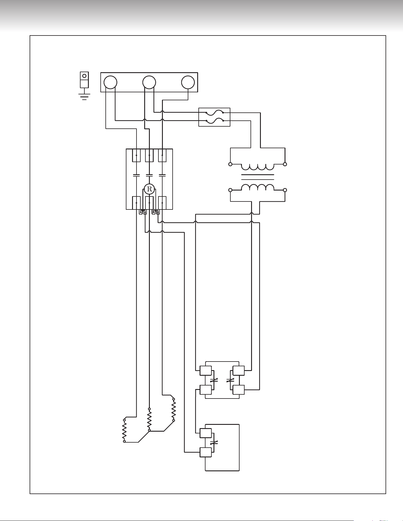
17
Figure 19
INSTALLATION INSTRUCTIONS
GROUND/
MISE À LA TERRE
FUSES/FUSIBLES
3 AMP., CLASS/CATÉGORIE G
HIGH LIMIT SWITCH/
INTERRUPTEUR
HAUTE TEMPÉRATURE
600V
240V
CONTROL
TRANSFORMER/
TRANSFORMATEUR
DE CONTRÔLE
THERMOSTAT
ELEMENTS/
ÉLÉMENTS
CONTACTOR/
CONTACTEUR
FUSES/FUSIBLES
3 AMP., CLASS/CATÉGORIE G
600V
240V
CONTROL
TRANSFORMER/
TRANSFORMATEUR
DE CONTRÔLE
FUSES/FUSIBLES
3 AMP., CLASS/CATÉGORIE G
600V
240V
CONTROL
TRANSFORMER/
TRANSFORMATEUR
DE CONTRÔLE
MISE À LA TERRE
INTERRUPTEUR
HAUTE TEMPÉRATURE
THERMOSTAT
ÉLÉMENTS
CONTACTEUR
GROUND
HIGH LIMIT SWITCH
THERMOSTAT
ELEMENTS
CONTACTOR
HIGH LIMIT SWITCH/
INTERRUPTEUR
HAUTE TEMPÉRATURE
THERMOSTAT
TO CONTACTOR/
VERS CONTACTEUR
TO CONTACTOR/
VERS CONTACTEUR
FROM CURRENT
TRANSFORMER/
DU TRANSFORMATEUR
DE CONTRÔLE
INTERRUPTEUR
HAUTE TEMPÉRATURE
THERMOSTAT
VERS CONTACTEUR
VERS CONTACTEUR
DU TRANSFORMATEUR
DE CONTRÔLE
HIGH LIMIT SWITCH
THERMOSTAT
TO CONTACTOR
TO CONTACTOR
FROM CURRENT
TRANSFORMER
ALTERNATIVE
THERMOSTAT-HIGH LIMIT
CONSTRUCTION
POWER DISTRIBUTION BLOCK/BORNIER DE DISTRIBUTIONBORNIER DE DISTRIBUTIONPOWER DISTRIBUTION BLOCK
ALTERNATIVE
THERMOSTAT-HIGH LIMIT
CONSTRUCTION/ALTERNATIVE
DE BRANCHEMENT DE
THERMOSTAT ET INTERRUPTEUR
HAUTE TEMPÉRATURE
ALTERNATIVE DE BRANCHEMENT DE
THERMOSTAT ET INTERRUPTEUR
HAUTE TEMPÉRATURE
GROUND/
MISE À LA TERRE
FUSES/FUSIBLES
3 AMP., CLASS/CATÉGORIE G
HIGH LIMIT SWITCH/
INTERRUPTEUR
HAUTE TEMPÉRATURE
600V
240V
CONTROL
TRANSFORMER/
TRANSFORMATEUR
DE CONTRÔLE
THERMOSTAT
ELEMENTS/
ÉLÉMENTS
CONTACTOR/
CONTACTEUR
FUSIBLES
3 AMP., CATÉGORIE G
600V
240V
TRANSFORMATEUR
DE CONTRÔLE
FUSES
3 AMP., CLASS G
600V
240V
CONTROL
TRANSFORMER
MISE À LA TERRE
INTERRUPTEUR
HAUTE TEMPÉRATURE
THERMOSTAT
ÉLÉMENTS
CONTACTEUR
GROUND
HIGH LIMIT SWITCH
THERMOSTAT
ELEMENTS
CONTACTOR
POWER DISTRIBUTION BLOCK/BORNIER DE DISTRIBUTIONBORNIER DE DISTRIBUTION
POWER DISTRIBUTION BLOCK
RED/ROUGE
RED/ROUGE
BLACK/NOIR
RED/ROUGE
BLACK/NOIR
BLACK/NOIR
BLUE/BLEU
NOIR
ROUGE
BLEU
BLACK
RED
BLUE
RED/ROUGE
RED/ROUGE
BLACK/NOIR
BLACK/NOIR
RED/ROUGE
RED/ROUGERED/ROUGE
Ancien Nom : Commer_50-80_102 Nouveau Nom : DF-Comm-50-80-600V-3Ele
ROUGE
ROUGE
NOIR
NOIR
ROUGE
ROUGE
NOIR
NOIR
ROUGE
ROUGEROUGE
BLEU
Ancien Nom : Commer_50-80_102 Nouveau Nom : DF-Comm-50-80-600V-3Ele
RED
RED
BLACK
BLACK
RED
RED
BLACK
BLACK
RED
REDRED
BLUE
Ancien Nom : Commer_50-80_102 Nouveau Nom : DF-Comm-50-80-600V-3Ele
BLUE/BLEU
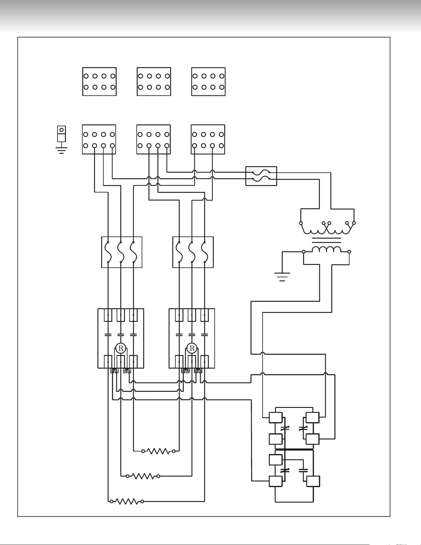
600 Volts / 3 Phases
Wiring diagram for commercial electric
water heater models 105, 108 with 3 elements
18
Figure 20
INSTALLATION INSTRUCTIONS
HIGH LIMIT SWITCH/
INTERRUPTEUR
HAUTE TEMPÉRATURE
600V
240V
GROUND/
MISE À LA TERRE
FUSES/FUSIBLES
3 AMP., CLASS/CATÉGORIE G
CONTROL
TRANSFORMER/
TRANSFORMATEUR
DE CONTRÔLE
ELEMENTS/
ÉLÉMENTS
ELEMENTS/
ÉLÉMENTS
CONTACTORS/
CONTACTEURS
THERMOSTAT
600V
240V
FUSIBLES
3 AMP., CATÉGORIE G
TRANSFORMATEUR
DE CONTRÔLE
600V
240V
FUSES
3 AMP., CATÉGORIE G
CONTROL
TRANSFORMER
INTERRUPTEUR
HAUTE TEMPÉRATURE
MISE À LA TERRE
ÉLÉMENTS
ÉLÉMENTS
CONTACTEURS
THERMOSTAT
HIGH LIMIT SWITCH
GROUND
ELEMENTS
ELEMENTS
CONTACTORS
THERMOSTAT
POWER DISTRIBUTION BLOCK POWER DISTRIBUTION BLOCK/BORNIER DE DISTRIBUTIONBORNIER DE DISTRIBUTION
HIGH LIMIT SWITCH/
INTERRUPTEUR
HAUTE TEMPÉRATURE
600V
240V
GROUND/
MISE À LA TERRE
FUSES/FUSIBLES
3 AMP., CLASS/CATÉGORIE G
CONTROL
TRANSFORMER/
TRANSFORMATEUR
DE CONTRÔLE
600V
240V
FUSIBLES
3 AMP., CATÉGORIE G
TRANSFORMATEUR
DE CONTRÔLE
600V
240V
FUSES
3 AMP., CLASS G
CONTROL
TRANSFORMER
ELEMENTS/
ÉLÉMENTS
ELEMENTS/
ÉLÉMENTS
CONTACTORS/
CONTACTEURS
INTERRUPTEUR
HAUTE TEMPÉRATURE
MISE À LA TERRE
ÉLÉMENTS
ÉLÉMENTS
CONTACTEURS
HIGH LIMIT SWITCH
POWER DISTRIBUTION BLOCK
GROUND
ELEMENTS
ELEMENTS
CONTACTORS
POWER DISTRIBUTION BLOCK/BORNIER DE DISTRIBUTIONBORNIER DE DISTRIBUTION
BLACK/NOIR
RED/ROUGE
NOIR
ROUGE
BLACK
RED
BLUE/BLEU
BLACK/NOIR
RED/ROUGE
RED/ROUGE
RED/ROUGE
RED/ROUGE
RED/ROUGE
RED/ROUGE
RED/ROUGE
BLACK/NOIR
RED/ROUGE
RED/ROUGE
RED/ROUGERED/ROUGE
BLACK/NOIR
BLACK/NOIR
BLACK/NOIR
RED/ROUGE
Ancien Nom : Commer_50-80_101 Nouveau Nom : DF-Comm-50-80-600V-6Ele
THERMOSTAT
BLUE/BLEU
BLEU
ROUGE
ROUGE
ROUGE
ROUGE
ROUGE
ROUGE
ROUGE
NOIR
ROUGE
ROUGE
ROUGE ROUGE
NOIR
NOIR
NOIR
NOIR
ROUGE
Ancien Nom : Commer_50-80_101 Nouveau Nom : DF-Comm-50-80-600V-6Ele
THERMOSTAT
BLEU
RED
REDRED
BLUE
BLACK
BLACK
NOIR
BLACK/NOIR
BLACK
BLACK
RED
RED
RED
RED
RED
RED
RED
BLACK
RED
BLACK
RED
Ancien Nom : Commer_50-80_101 Nouveau Nom : DF-Comm-50-80-600V-6Ele
THERMOSTAT
BLUE
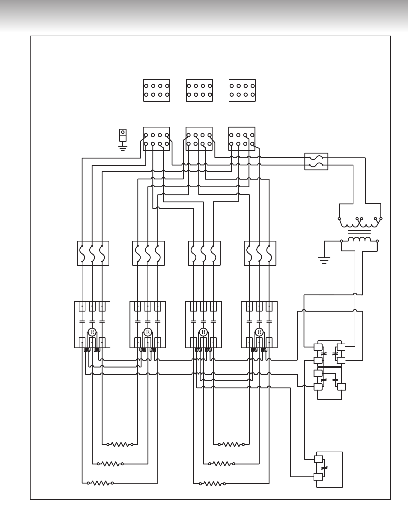
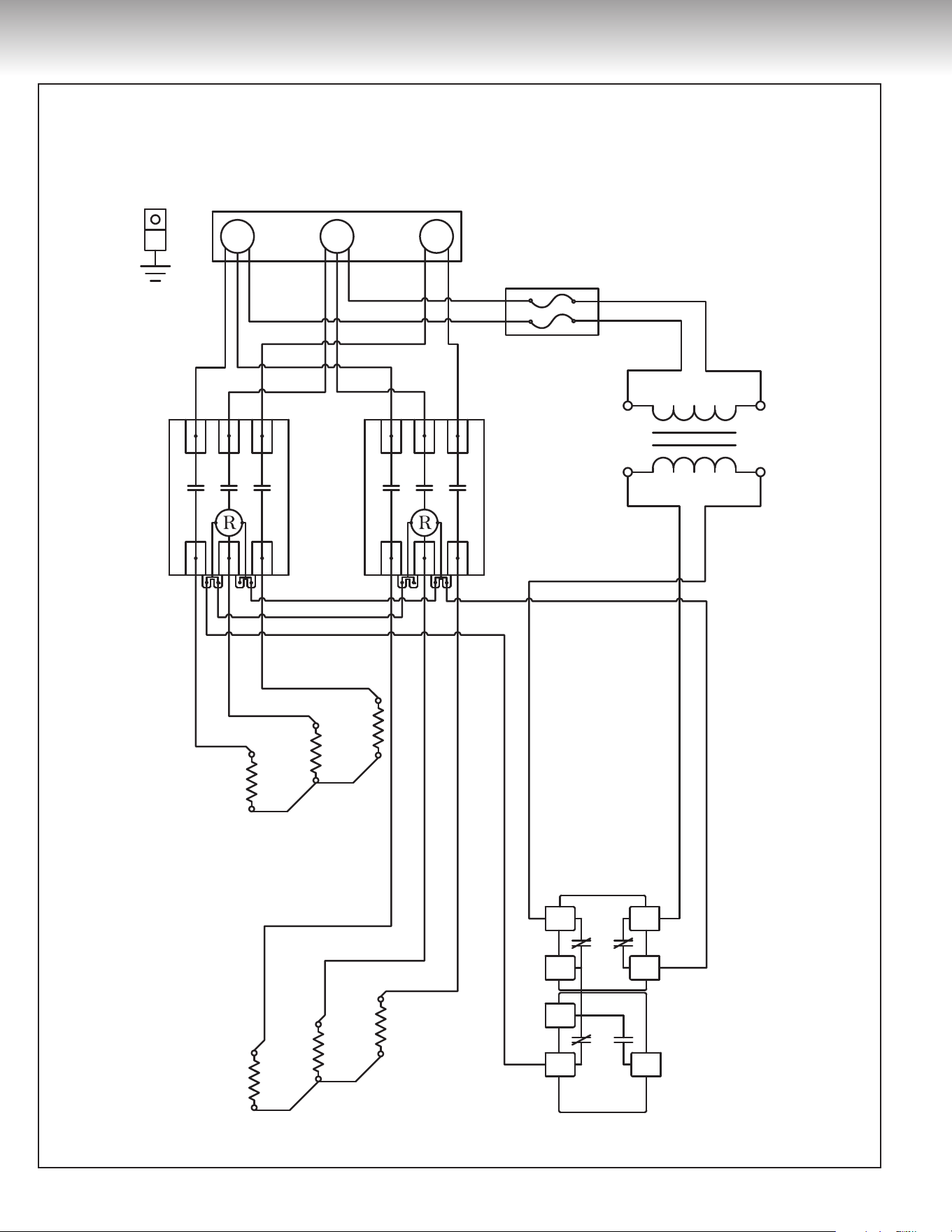
600 Volts / 3 Phases
Wiring diagram for commercial electric
water heater models 105, 108 with 6 elements
19
Figure 21
INSTALLATION INSTRUCTIONS
HIGH LIMIT SWITCH/
INTERRUPTEUR
HAUTE TEMPÉRATURE
600V
240V
GROUND/
MISE À LA TERRE
FUSES/FUSIBLES
3 AMP., CLASS/CATÉGORIE G
CONTROL
TRANSFORMER/
TRANSFORMATEUR
DE CONTRÔLE
THERMOSTAT
ELEMENTS/
ÉLÉMENTS
ELEMENTS/
ÉLÉMENTS
ELEMENTS/
ÉLÉMENTS
CONTACTORS/
CONTACTEURS
600V
240V
FUSIBLES
3 AMP., CATÉGORIE G
TRANSFORMATEUR
DE CONTRÔLE
600V
240V
FUSES
3 AMP., CLASS G
CONTROL
TRANSFORMER
INTERRUPTEUR
HAUTE TEMPÉRATURE
MISE À LA TERRE
THERMOSTAT
ÉLÉMENTS
ÉLÉMENTS
ÉLÉMENTS
CONTACTEURS
HIGH LIMIT SWITCH
GROUND
THERMOSTAT
ELEMENTS
ELEMENTS
ELEMENTS
CONTACTORS
POWER DISTRIBUTION BLOCK POWER DISTRIBUTION BLOCK/BORNIER DE DISTRIBUTIONBORNIER DE DISTRIBUTION
HIGH LIMIT SWITCH/
INTERRUPTEUR
HAUTE TEMPÉRATURE
600V
240V
GROUND/
MISE À LA TERRE
FUSES/FUSIBLES
3 AMP., CLASS/CATÉGORIE G
CONTROL
TRANSFORMER/
TRANSFORMATEUR
DE CONTRÔLE
600V
240V
FUSIBLES
3 AMP., CATÉGORIE G
TRANSFORMATEUR
DE CONTRÔLE
600V
240V
FUSES
3 AMP., CLASS G
CONTROL
TRANSFORMER
THERMOSTAT
ELEMENTS/
ÉLÉMENTS
ELEMENTS/
ÉLÉMENTS
ELEMENTS/
ÉLÉMENTS
CONTACTORS/
CONTACTEURS
Ancien Nom : Commer_50-80_100 Nouveau Nom : DF-Comm-50-80-600V-9Ele
INTERRUPTEUR
HAUTE TEMPÉRATURE
MISE À LA TERRE
THERMOSTAT
ÉLÉMENTS
ÉLÉMENTS
ÉLÉMENTS
CONTACTEURS
Ancien Nom : Commer_50-80_100 Nouveau Nom : DF-Comm-50-80-600V-9Ele
HIGH LIMIT SWITCH
GROUND
THERMOSTAT
ELEMENTS
ELEMENTS
ELEMENTS
CONTACTORS
Ancien Nom : Commer_50-80_100 Nouveau Nom : DF-Comm-50-80-600V-9Ele
POWER DISTRIBUTION BLOCK
POWER DISTRIBUTION BLOCK/BORNIER DE DISTRIBUTIONBORNIER DE DISTRIBUTION
RED/ROUGE
RED/ROUGE
RED/ROUGE
RED/ROUGE
BLACK/NOIR
RED/ROUGE
BLACK/NOIR
RED/ROUGE
RED/ROUGE
RED/ROUGE
RED/ROUGE
RED/ROUGE
BLUE/BLEU
BLUE/BLEU
BLUE/BLEU
BLACK/NOIRBLACK/NOIR
BLACK/NOIR
BLACK/NOIR
BLACK/NOIR
ROUGE
NOIR
RED
BLACK
RED/ROUGE
RED/ROUGE
BLACK/NOIR
RED/ROUGE
RED/ROUGE
RED/ROUGE
RED/ROUGE
RED/ROUGE
RED/ROUGE
RED/ROUGE
BLACK/NOIR
ROUGE
ROUGE
ROUGE
ROUGE
NOIR
ROUGE
NOIR
ROUGE
ROUGE
ROUGE
ROUGE
BLEU
BLEU
BLEU
NOIRNOIR
NOIR
NOIR
ROUGE
ROUGE
NOIR
ROUGE
ROUGE
ROUGE
ROUGE
ROUGE
ROUGE
ROUGE
NOIR
RED
RED
RED
RED
BLACK
RED
BLACK
RED
RED
RED
RED
BLUE
BLUE
BLUE
BLACKBLACK
BLACK
BLACK
RED
RED
RED
BLACK
RED
RED
RED
RED
RED
RED
BLACK
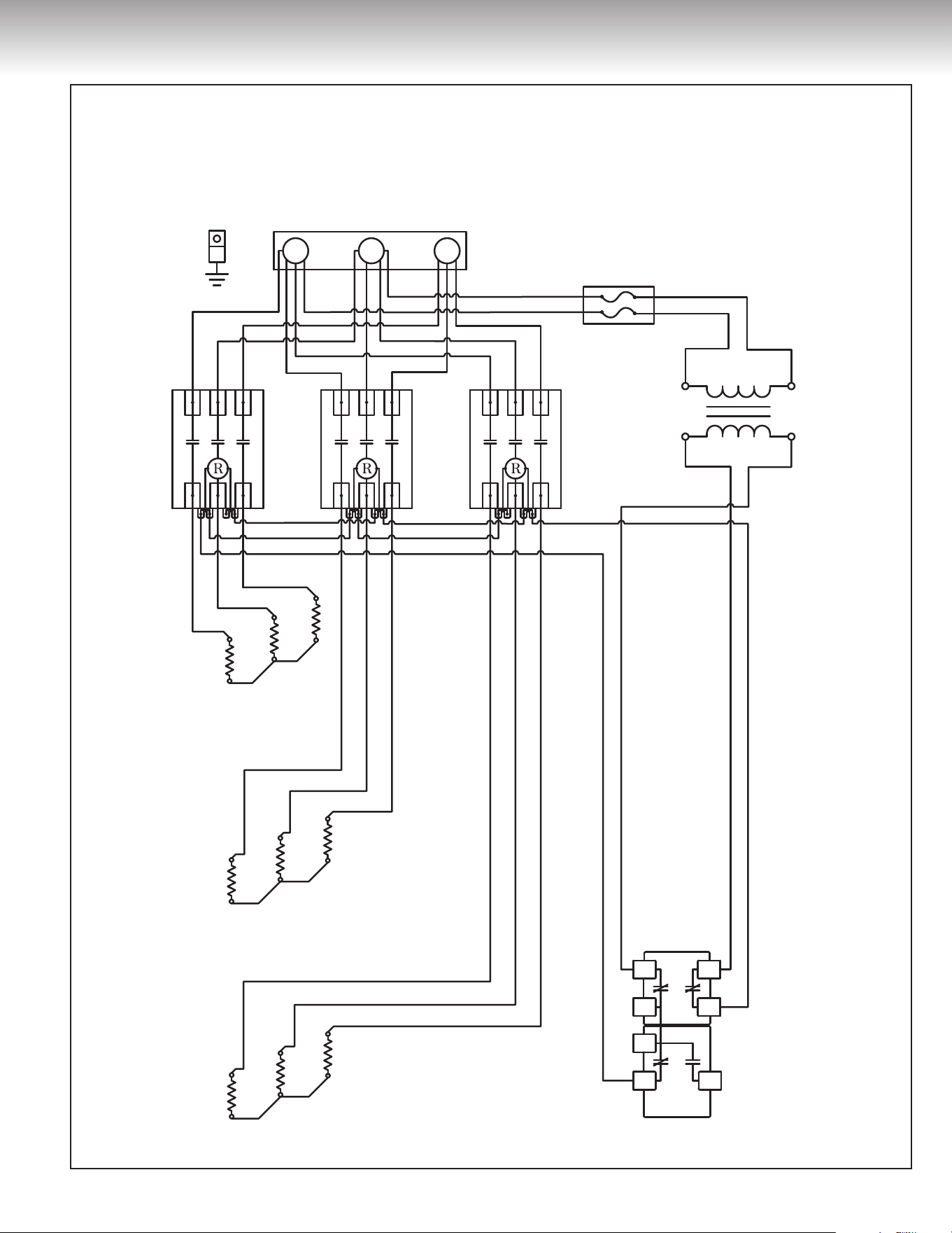
600 Volts / 3 Phases
Wiring diagram for commercial electric
water heater models 105, 108 with 9 elements
20
Figure 22
INSTALLATION INSTRUCTIONS
HIGH LIMIT SWITCH/
INTERRUPTEUR
HAUTE TEMPÉRATURE
600V
240V
INTERRUPTEUR
HAUTE TEMPÉRATURE
600V
240V
HIGH LIMIT SWITCH
600V
240V
POWER DISTRIBUTION BLOCK/BORNIER DE DISTRIBUTION
GROUND/
MISE À LA TERRE
FUSES/FUSIBLES
3 AMP., CLASS/CATÉGORIE G
CONTROL
TRANSFORMER/
TRANSFORMATEUR
DE CONTRÔLE
THERMOSTAT
ELEMENTS/
ÉLÉMENTS
CONTACTOR/
CONTACTEUR
BORNIER DE DISTRIBUTION
MISE À LA TERRE
FUSIBLES
3 AMP., CATÉGORIE G
TRANSFORMATEUR
DE CONTRÔLE
THERMOSTAT
ÉLÉMENTS
CONTACTEUR
POWER DISTRIBUTION BLOCK
GROUND
FUSES
3 AMP., CLASS G
CONTROL
TRANSFORMER
THERMOSTAT
ELEMENTS
CONTACTOR
HIGH LIMIT SWITCH/
INTERRUPTEUR
HAUTE TEMPÉRATURE
600V
240V
INTERRUPTEUR
HAUTE TEMPÉRATURE
600V
240V
HIGH LIMIT SWITCH
600V
240V
GROUND/
MISE À LA TERRE
FUSES/FUSIBLES
3 AMP., CLASS/CATÉGORIE G
CONTROL
TRANSFORMER/
TRANSFORMATEUR
DE CONTRÔLE
THERMOSTAT
ELEMENTS/
ÉLÉMENTS
CONTACTOR/
CONTACTEUR
MISE À LA TERRE
FUSIBLES
3 AMP., CATÉGORIE G
TRANSFORMATEUR
DE CONTRÔLE
THERMOSTAT
ÉLÉMENTS
CONTACTEUR
GROUND
FUSES
3 AMP., CLASS G
CONTROL
TRANSFORMER
THERMOSTAT
ELEMENTS
CONTACTOR
POWER DISTRIBUTION BLOCK/BORNIER DE DISTRIBUTIONBORNIER DE DISTRIBUTION
POWER DISTRIBUTION BLOCK
RED/ROUGE
RED/ROUGE
BLUE/BLEU
RED/ROUGE
RED/ROUGE
RED/ROUGE
RED/ROUGE
RED/ROUGE
BLACK/NOIR
BLACK/NOIR
BLACK/NOIR BLUE/BLEU
BLACK/NOIR
BLACK/NOIR
ROUGE
BLEU
ROUGE
ROUGE
ROUGE
ROUGE
ROUGE ROUGE
NOIR NOIR
NOIR BLEU
NOIR
NOIR
RED
RED
RED
RED
BLUE
RED
RED RED
BLACK BLACK
BLACK BLUE
BLACK
BLACK
Ancien Nom : Commer_Wiring_102 Nouveau Nom : DF-Comm-120-600V-3EleAncien Nom : Commer_Wiring_102 Nouveau Nom : DF-Comm-120-600V-3EleAncien Nom : Commer_Wiring_102 Nouveau Nom : DF-Comm-120-600V-3Ele
600 Volts / 3 Phases
Wiring diagram for commercial electric
water heater models 112 with 3 elements
21
Figure 23
INSTALLATION INSTRUCTIONS
Ancien Nom : Commer_Wiring_101 Nouveau Nom : DF-Comm-120-600V-6Ele
HIGH LIMIT SWITCH/
INTERRUPTEUR
HAUTE TEMPÉRATURE
600V
240V
GROUND/
MISE À LA TERRE
FUSES/FUSIBLES
3 AMP., CLASS/CATÉGORIE G
CONTROL
TRANSFORMER/
TRANSFORMATEUR
DE CONTRÔLE
600V
240V
FUSIBLES
3 AMP., CATÉGORIE G
TRANSFORMATEUR
DE CONTRÔLE
600V
240V
FUSES
3 AMP., CLASS G
CONTROL
TRANSFORMER
THERMOSTAT
THERMOSTAT
CONTACTORS/
CONTACTEURS
HIGH LIMIT SWITCH/
INTERRUPTEUR
HAUTE TEMPÉRATURE
600V
240V
GROUND/
MISE À LA TERRE
FUSES/FUSIBLES
3 AMP., CLASS/CATÉGORIE G
CONTROL
TRANSFORMER/
TRANSFORMATEUR
DE CONTRÔLE
THERMOSTAT
THERMOSTAT
CONTACTORS/
CONTACTEURS
Ancien Nom : Commer_Wiring_101 Nouveau Nom : DF-Comm-120-600V-6Ele
INTERRUPTEUR
HAUTE TEMPÉRATURE
MISE À LA TERRE
THERMOSTAT
THERMOSTAT
ÉLÉMENTS
ÉLÉMENTS
CONTACTEURS
INTERRUPTEUR
HAUTE TEMPÉRATURE
MISE À LA TERRE
THERMOSTAT
THERMOSTAT
CONTACTEURS
Ancien Nom : Commer_Wiring_101 Nouveau Nom : DF-Comm-120-600V-6Ele
HIGH LIMIT SWITCH
GROUND
THERMOSTAT
THERMOSTAT
CONTACTORS
HIGH LIMIT SWITCH
GROUND
THERMOSTAT
THERMOSTAT
CONTACTORS
ELEMENTS
ELEMENTS
ELEMENTS/
ÉLÉMENTS
ELEMENTS/
ÉLÉMENTS
600V
240V
FUSES/FUSIBLES
3 AMP., CLASS/CATÉGORIE G
CONTROL
TRANSFORMER/
TRANSFORMATEUR
DE CONTRÔLE
600V
240V
FUSES/FUSIBLES
3 AMP., CLASS/CATÉGORIE G
CONTROL
TRANSFORMER/
TRANSFORMATEUR
DE CONTRÔLE
POWER DISTRIBUTION BLOCK
POWER DISTRIBUTION BLOCK/BORNIER DE DISTRIBUTIONBORNIER DE DISTRIBUTION
POWER DISTRIBUTION BLOCK
POWER DISTRIBUTION BLOCK/BORNIER DE DISTRIBUTIONBORNIER DE DISTRIBUTION
BLACK/NOIR
BLACK/NOIR
BLACK/NOIR
BLACK/NOIR
BLUE/BLEU
RED/ROUGE
NOIR
ROUGE
BLACK
RED
RED/ROUGE
RED/ROUGERED/ROUGE
BLACK/NOIR
RED/ROUGE
BLACK/NOIR
BLUE/BLEU
RED/ROUGE
RED/ROUGE
RED/ROUGE
RED/ROUGE
RED/ROUGE
RED/ROUGE
BLUE/BLEU
RED/ROUGE
BLACK/NOIR
RED/ROUGE
NOIR
NOIR
NOIR
BLEU
ROUGE
ROUGEROUGE
NOIR
ROUGE
NOIR
BLEU
ROUGE
ROUGE
ROUGE
ROUGE
ROUGE
ROUGE
BLEU
ROUGE
NOIR
ROUGE
BLACK
BLACK
BLACK
BLUE
RED
REDRED
BLACK
RED
BLACK
BLUE
RED
RED
RED
RED
RED
RED
BLUE
RED
BLACK
RED
ÉLÉMENTS
ÉLÉMENTS
ELEMENTS
ELEMENTS
ELEMENTS/
ÉLÉMENTS
ELEMENTS/
ÉLÉMENTS
600 Volts / 3 Phases
Wiring diagram for commercial electric
water heater models 112 with 6 elements
22
Figure 24
INSTALLATION INSTRUCTIONS
HIGH LIMIT SWITCH/
INTERRUPTEUR
HAUTE TEMPÉRATURE
GROUND/
MISE À LA TERRE
FUSES/FUSIBLES
3 AMP., CLASS/CATÉGORIE G
CONTROL
TRANSFORMER/
TRANSFORMATEUR
DE CONTRÔLE
THERMOSTAT
THERMOSTAT
THERMOSTAT
ELEMENTS/
ÉLÉMENTS
ELEMENTS/
ÉLÉMENTS
ELEMENTS/
ÉLÉMENTS
CONTACTORS/
CONTACTEURS
INTERRUPTEUR
HAUTE TEMPÉRATURE
MISE À LA TERRE
THERMOSTAT
THERMOSTAT
THERMOSTAT
ÉLÉMENTS
ÉLÉMENTS
ÉLÉMENTS
CONTACTEURS
HIGH LIMIT SWITCH
GROUND
THERMOSTAT
THERMOSTAT
THERMOSTAT
ELEMENTS
ELEMENTS
ELEMENTS
CONTACTORS
600V
240V
FUSIBLES
3 AMP., CATÉGORIE G
TRANSFORMATEUR
DE CONTRÔLE
600V
240V
FUSES
3 AMP., CLASS G
CONTROL
TRANSFORMER
600V
240V
POWER DISTRIBUTION BLOCK POWER DISTRIBUTION BLOCK/BORNIER DE DISTRIBUTION
BORNIER DE DISTRIBUTION
HIGH LIMIT SWITCH/
INTERRUPTEUR
HAUTE TEMPÉRATURE
GROUND/
MISE À LA TERRE
FUSES/FUSIBLES
3 AMP., CLASS/CATÉGORIE G
CONTROL
TRANSFORMER/
TRANSFORMATEUR
DE CONTRÔLE
CONTROL
TRANSFORMER
FUSIBLES
3 AMP., CATÉGORIE G
TRANSFORMATEUR
DE CONTRÔLE
FUSES
3 AMP., CLASS G
THERMOSTAT
THERMOSTAT
THERMOSTAT
ELEMENTS/
ÉLÉMENTS
ELEMENTS/
ÉLÉMENTS
ELEMENTS/
ÉLÉMENTS
CONTACTORS/
CONTACTEURS
INTERRUPTEUR
HAUTE TEMPÉRATURE
MISE À LA TERRE
THERMOSTAT
THERMOSTAT
THERMOSTAT
ÉLÉMENTS
ÉLÉMENTS
ELEMENTS/
ÉLÉMENTS
CONTACTEURS
HIGH LIMIT SWITCH
GROUND
THERMOSTAT
THERMOSTAT
THERMOSTAT
ELEMENTS
ELEMENTS
ELEMENTS
CONTACTORS
POWER DISTRIBUTION BLOCK
POWER DISTRIBUTION BLOCK/BORNIER DE DISTRIBUTION
BORNIER DE DISTRIBUTION
RED/ROUGE
RED/ROUGE
RED/ROUGE
BLACK/NOIR
RED/ROUGE
BLACK/NOIR
BLACK/NOIR
BLACK/NOIR
BLACK/NOIR
BLUE/BLEU
BLUE/BLEU
BLUE/BLEU
BLUE/BLEU
RED/ROUGE
RED/ROUGE
RED/ROUGE
RED/ROUGE
RED/ROUGE
RED/ROUGE
BLACK/NOIRBLACK/NOIRBLACK/NOIR
BLACK/NOIR
YELLOW/JAUNE
YELLOW/JAUNE
RED/ROUGE
RED/ROUGE
RED/ROUGE
RED/ROUGE
RED/ROUGE
RED/ROUGE
RED/ROUGE
RED/ROUGE
Ancien Nom : Commer_Wiring_100 Nouveau Nom : DF-Comm-120-600V-9Ele
600V
240V
ROUGE
NOIR
600V
240V
ROUGE
ROUGE
ROUGE
NOIR
ROUGE
NOIR
NOIR
NOIR
NOIR
BLEU
BLEU
BLEU
BLEU
ROUGE
ROUGE
ROUGE
ROUGE
ROUGE
RED
BLACK
600V
240V
RED
NOIRNOIRNOIR
JAUNE
JAUNE
ROUGE
ROUGE
ROUGE
ROUGE
ROUGE
ROUGE
ROUGE
ROUGE
Ancien Nom : Commer_Wiring_100 Nouveau Nom : DF-Comm-120-600V-9Ele
RED
RED
RED
BLACK
RED
BLACK
BLACK
BLACK
BLACK
BLUE
BLUE
BLUE
BLUE
RED
RED
RED
RED
BLACKBLACKBLACK
YELLOW
RED
RED
RED
RED
RED
RED
RED
RED
Ancien Nom : Commer_Wiring_100 Nouveau Nom : DF-Comm-120-600V-9Ele
600 Volts / 3 Phases
Wiring diagram for commercial electric
water heater models 112 with 9 elements
23
CONVERSION INSTRUCTIONS
Field Conversions
All water heaters are manufactured and shipped from the factory pre-
wired for phase, voltage, and wattage conversion. (No phase or
voltage conversion on 600V Models. In addition, no other
voltage can be converted to 600V).
Phase Conversion
DANGER
WARNING
CAUTION
AVERTISSEMENT
ATTENTION
600V Models cannot be converted to Single Phase.
DANGER
WARNING
CAUTION
AVERTISSEMENT
ATTENTION
Two (2) and four (4) elements water heaters are single phase and
cannot be converted to three (3) phases.
DANGER
WARNING
CAUTION
AVERTISSEMENT
ATTENTION
Disconnect from power supply before attempting the conversion
procedure. Read all instructions before proceeding with the
conversion procedure.
Surface mount thermostat
– Three (3) phases to single phase (See Figure 25)
Figure 25
Three (3) Phases
L1 L2 L3
Power distribution block
BLACK RED BLUE &
YELLOW
1.
Disconnect all blue and yellow wires from terminal L3
on the power distribution block.
2.
Reconnect all blue wires to terminal L1.
3.
Reconnect all yellow wires to terminal L2.
4.
Connect incoming power to terminal block L1 and L2.
Surface mount thermostat
– Single phase to three (3) phases (See Figure 26)
Figure 26
BLACK & RED &
BLUE YELLOW
Single Phase
L1 L2
Power distribution block
1. Disconnect all blue wires from terminal L1 on the distribution block.
2. Disconnect all yellow wires from terminal L2.
3. Reconnect all blue and yellow wires to terminal L3.
4. Connect incoming power to terminal block L1, L2, and L3
Check that all electrical connections are tightly secured and that wire
routings are neat and orderly. Make sure that you have done the
proper wiring has specified in these instructions and on the wiring
diagram.
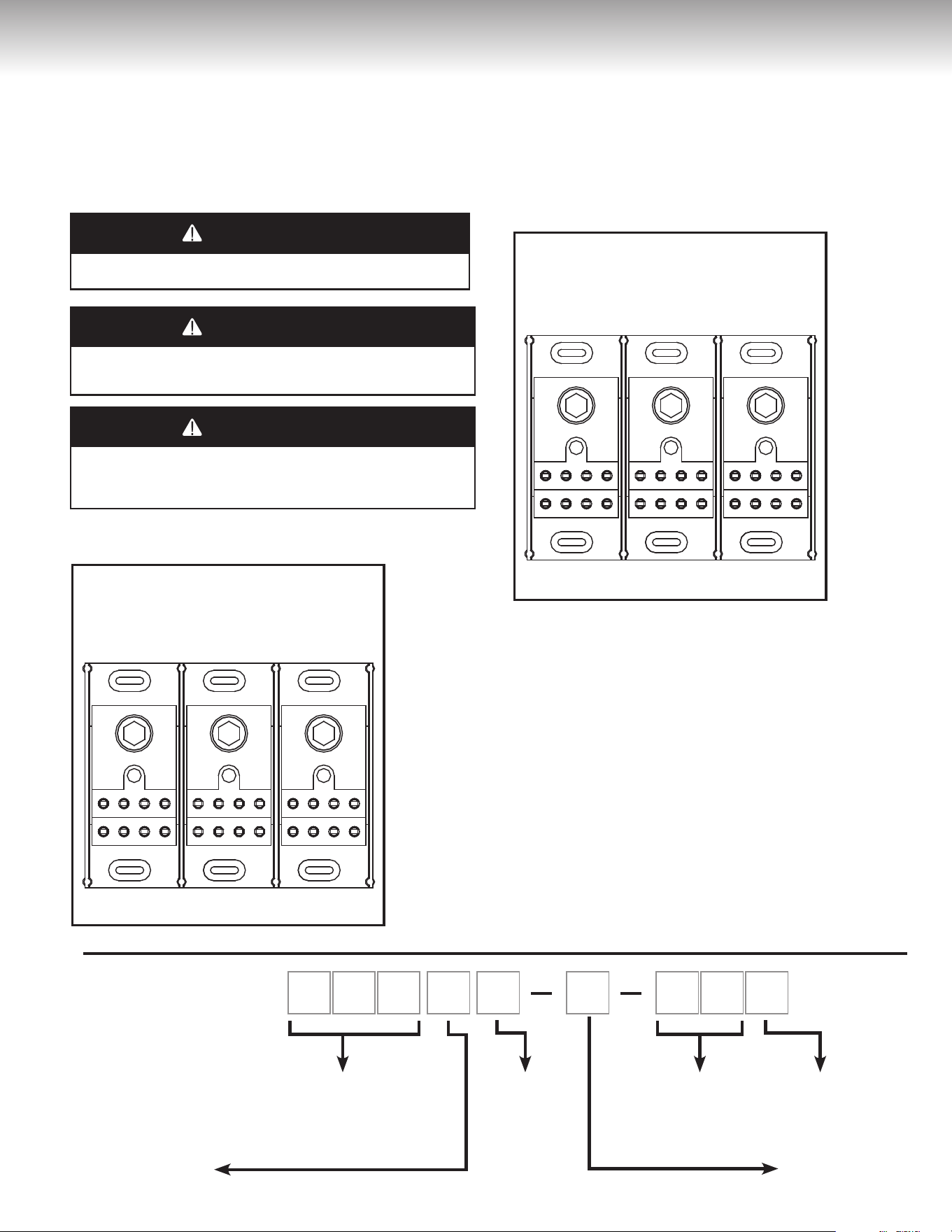
Note: Actual part may differ slightly from illustration depending on
model.
TANK CAPACITY
105 = 40.5
Imp. gal
/ 48.6
US Gal.
108 = 61.4
Imp. gal
/ 73.7
US Gal.
112 = 99.1
Imp. gal
/ 119.0
US Gal.
INPUT IN
KILOWATTS
ex: 27 = 27kW
SURFACE MOUNT
THERMOSTAT
NUMBER
OF ELEMENTS
NUMBER
OF PHASES
VOLTAGE
A = 208 V
B = 240 V
C = 600 V
D = 480 V
1 0 5 6 B 3 2 7 S
THE STRUCTURE
OF THE
MODEL NUMBER
24
CONVERSION INSTRUCTIONS
Model & Type
Number
of
elements
Desired
Total Input, (kW)
DESIRED VOLTAGE
208 Volts 240 Volts 480 Volts
Conversion Kit Part Numbers
105, 108, or
112 Models
Light Duty 2
3 06999301 06999309 06999325
4.5 06999302 06999310 06999326
5 06999303 06999311 06999327
6 N/A 06999312 06999328
Medium Duty 4
6 06999305 06999313 06999329
9 06999306 06999314 06999330
10 06999307 06999315 06999331
12 N/A 06999316 06999332
Heavy Duty
3
6 06999101
06999113
06999143
9 06999102 06999114 06999144
12
06999103 06999115 06999145
13.5 06999104 06999116 06999146
15 06999105 06999117 06999147
18 N/A 06999118 06999148
6
18 06999106 06999119 06999149
24 06999107 06999120 06999150
27 06999108 06999121 06999151
30 06999109* 06999122 06999152
36 N/A 06999123* 06999153
9
36 06999110 06999124 06999154
40.5 06999111 06999125 06999155
45 06999112 06999126 06999156
54 N/A 06999127 06999157
Model & Type
Number
of
elements
Desired
Total Input,
(kW)
Conversion
Kit Part
Numbers
105, 108, 112 600V / 3 Phase Models
Heavy
Duty
3
6 06999158
9 06999159
12 06999160
13.5 06999161
15 06999162
18 06999163
6
18 06999164
24 06999165
27 06999166
30 06999167
36 06999168
9
36 06999169
40.5 06999170
45 06999171
54 06999172
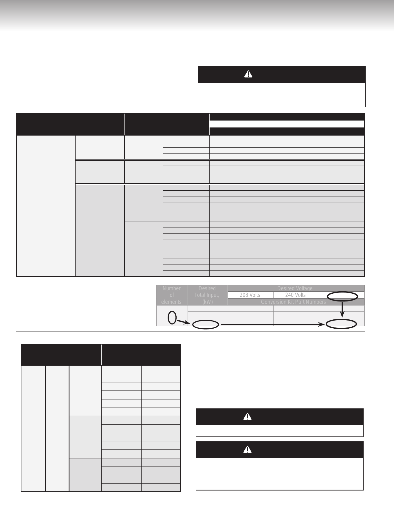
WATTAGE AND VOLTAGE CONVERSION FOR 208V, 240V &
480V MODELS
Conversion kits are available to modify total power (kW) and/or
voltage (V) of the water heater in the field. Refer to Table 2 for the
selection of the appropriate conversion kit.
1. Find the “Number of elements” in the water heater to be converted
(4
th
digit of model number on the rating plate, see page 23).
2. Find the “Desired total input (kW)” in Table 2 that matches the
number of elements.
3. Then, move across the Table 2 on the same row to the “Desired
Voltage” column. The appropriate Conversion Kit part number will
be the one where the “Desired total input” row intersects the
“Desired Voltage” column.
DANGER
WARNING
CAUTION
AVERTISSEMENT
ATTENTION
No addition or removal of heating elements in reference to the original
model is allowed in the conversion process. Failure to do so could result
in electrical shock and/or property damage, personal injury, or death.
WATTAGE CONVERSION FOR 600V MODELS
Conversion kits are available to modify total power (kW) of the water
heater in the field. Refer to Table 3 for the selection of the appropriate
conversion kit.
1. Find the “Number of elements” in the water heater you wish to convert.
2. Find the “Desired total input (kW)” in Table 3 that matches your
number of elements.
3. The appropriate Conversion Kit part number will be on the last
column of this row.
DANGER
WARNING
CAUTION
AVERTISSEMENT
ATTENTION
Voltage and phase conversion are not allowed on 600V models.
DANGER
WARNING
CAUTION
AVERTISSEMENT
ATTENTION
No addition or removal of heating elements in reference to the
original model is allowed in the conversion process. Failure to do so
could result in electrical shock and/or property damage, personal
injury, or death.
EXAMPLE: For a 6 element water heater to be
converted to 27 kW / 480V, the appropriate
Convertion Kit part number is 06999151.
Number
of
elements
Desired
Total Input,
(kW)
Desired Voltage
208 Volts 240 Volts
Conversion Kit Part Numbers
18 06999106 06999119 06999149
24 06999107 06999120 06999150
27 06999108 06999121
06999151
480 Volts
6
27
Table 2
Table 3
*IMPORTANT: Any 6-element model cannot be converted to 30kW/208V - 1 phase nor 36kW/ 240V-1 phase
25
OPERATING INSTRUCTIONS
Installation Checklist
Location
• Is the water heater located close to an adequate power supply and the main use of hot water? ................................................................. n
• Is the water heater protected from freezing temperatures? ........................................................................................................................... n
• Has a drain pan been installed and piped to a free-flowing drain? ................................................................................................................ n
• Can the element and thermostat access panels be opened for inspection, adjustment, and servicing of the elements and thermostats? ...... n
• Is the area where the water heater is located free of flammable vapours? ................................................................................................... n
Water Piping
• Has a temperature and pressure-relief valve been installed? .................................................................................................................................... n
• Does this valve have a discharge line installed and is it piped to a free-flowing drain? ................................................................................ n
• Have all the plumbing connections been properly installed and are they leak free? ..................................................................................... n
• Is the water heater completely filled with water and purged from all its air? ................................................................................................ n
• Does the network have protection against thermal expansion? ................................................................................................................... n
• Is the piping network equipped with pre-fabricated water hammer(s) suitably selected and positioned, if required? .................................. n
Wiring
• Does the power supply voltage match the voltage indicated on the water heater rating plate? ................................................................... n
• Has the correct size of wire and fusing or circuit breaker been used to supply the water heater with power? ............................................. n
• Is the water heater electrically grounded? ..................................................................................................................................................... n
• Have the electrical connections been checked, and are they secure? .......................................................................................................... n
Starting the Water Heater
Before turning “ON” the power
to your water heater, make sure
that you have read and
understood all of the instructions
and warnings in this manual and
on your water heater. If you
have any questions about
turning “ON” your water heater,
immediately contact a qualified
installer, service agency, or the
local electric utility.
DANGER
WARNING
CAUTION
AVERTISSEMENT
ATTENTION
DO NOT turn “ON” the power to this water heater if:
• It is not completely filled with water and purged from all its
air.
• The power supply voltage does not match the voltage listed
on the rating plate.
• Gasoline or other flammable vapours and liquids have been
stored in the vicinity of the water heater.
Failure to follow these instructions can result in property
damage, personal injury, or death.
• DO NOT open the electrical junction box or the
element access panel before the power to the water
heater is turned “OFF”.
• DO NOT ATTEMPT to repair or replace any of the
electrical components installed on the water heater
before the power to the water heater is turned “OFF”.
• DO NOT USE the water heater on a voltage other
than that specified on the water heater rating plate.
• DO NOT CONNECT the power supply wiring to
anywhere other than the power distribution block in
electrical junction box of the water heater.
• DO NOT TURN ON the power to the water heater
unless it is completely filled with water and purged
from all its air.
• DO NOT DRAIN the water heater unless the power
to the water heater has been turned “OFF”.
• DO NOT STORE or use gasoline or other flammable
vapours and liquids in the vicinity of this or any other
appliance.
WHAT TO DO IF YOU SMELL SMOKE
• Immediately turn “OFF” the power to the water heater.
• If after turning “OFF” the power the smoke continues,
call your local fire department.
• When the smoke has stopped, call a qualified service
technician to identify and repair the problem.
DANGER
WARNING
CAUTION
AVERTISSEMENT
ATTENTION
If the information in these instructions is not
followed exactly, a fire or explosion may result
causing property damage, personal injury, or death.
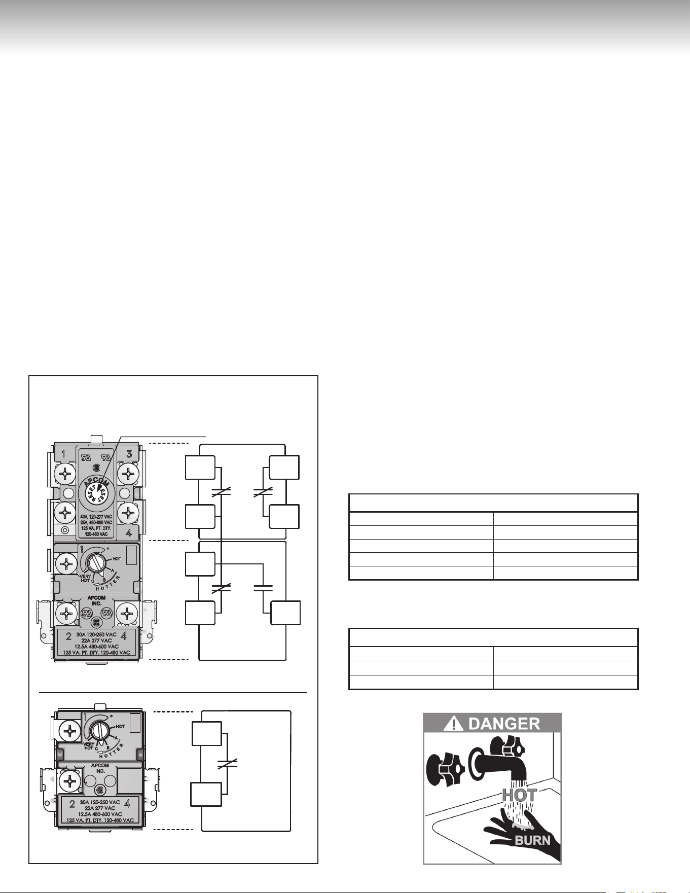
26
Start-up Procedure
1) Turn «ON» the circuit breaker at the main service panel.
2) Make sure the fuse box or power switch (if one exists) next to the
water heater is pushed to “ON”.
3) If you smell smoke, refer to What to do if you smell smoke.
4) Hot water should be available at the faucet within thirty (30) to sixty
(60) minutes.
5) If after one (1) hour you do not have any hot water, check that the
fuse or circuit breaker is in working condition.
6) If at this time you still do not have any hot water, call a qualified
service technician.
Note: If after one (1) hour you receive only a small amount of hot
water, check that the plumbing connections are not reversed.
Safety Controls
This water heater is equipped with a combination thermostat and
high limit switch that is located above the upper heating element. If
for any reason the temperature of the water becomes excessively
high, the high limit switch will open the circuit to the heating elements.
Once the control opens, it must be reset manually (See Figure 27).
To reset the high limit switch:
1) Turn “OFF” the power to the water heater.
2) Open the elements and thermostat(s) access panel and remove
the insulation.
3) Press the red reset button on the high limit switch.
4) Replace the insulation and close the element access panel
before turning “ON” the power to the water heater.
Water Temperature Regulation
The higher the setting, the greater the risk of scalding. Hot water can
cause third degree burns in less than one (1) second at 160°F
(71°C), in five (5) seconds at 140°F (60°C), and in thirty (30) seconds
at 130°F (54°C). In households where there are children, physically
challenged individuals, or seniors, mixing valves for point of use are
necessary as means of reducing the scalding potential of hot water.
The thermostat is factory set at 140°F (60°C) on all models.
To adjust the temperature on the thermostat:
1) Turn “OFF” the power to the water heater.
2) Open the elements and thermostat(s) access panel and remove
the insulation. (DO NOT remove the thermostat protective cover
if so equiped).
3) Using a small flat-head screwdriver, turn the thermostat dial to the
desired temperature setting (see Table 4a or 4b depending on
model.).
4) Replace the insulation and close the elements and thermostat(s)
access panel before turning “ON” the power to the water heater.
OPERATING INSTRUCTIONS
HIGH LIMIT
MANUAL RESET BUTTON
THERMOSTAT
THERMOSTAT
INTERRUPTEUR
DISPOSITIF DE RÉENCLENCHEMENT MANUEL
THERMOSTAT
HIGH LIMIT
MANUAL RESET BUTTON
THERMOSTAT
THERMOSTAT
INTERRUPTEUR
DISPOSITIF DE RÉENCLENCHEMENT MANUEL
THERMOSTAT
TEMPERATURE EQUIVALENCE
HOT 120˚F / 48.9˚C
A 130˚F / 54.4˚C
B 140˚F / 60.0˚C
C 150˚F / 65.5˚C
VERY HOT 160˚F / 71.1˚C
TEMPERATURE EQUIVALENCE
LO 140˚F / 60.0˚C
MED 160˚F / 71.1˚C
HI 180˚F / 82.2˚C
Figure 27
Combination Thermostat High limit
Thermostat only
Table 4a
All 105 models, 1083-1086-1089 models, 1123-1126-1129 models
Table 4b
1082-1084 models, 1122-1124 models
All 105 models, 1083-1086-1089 models,
1123-1126-1129 models
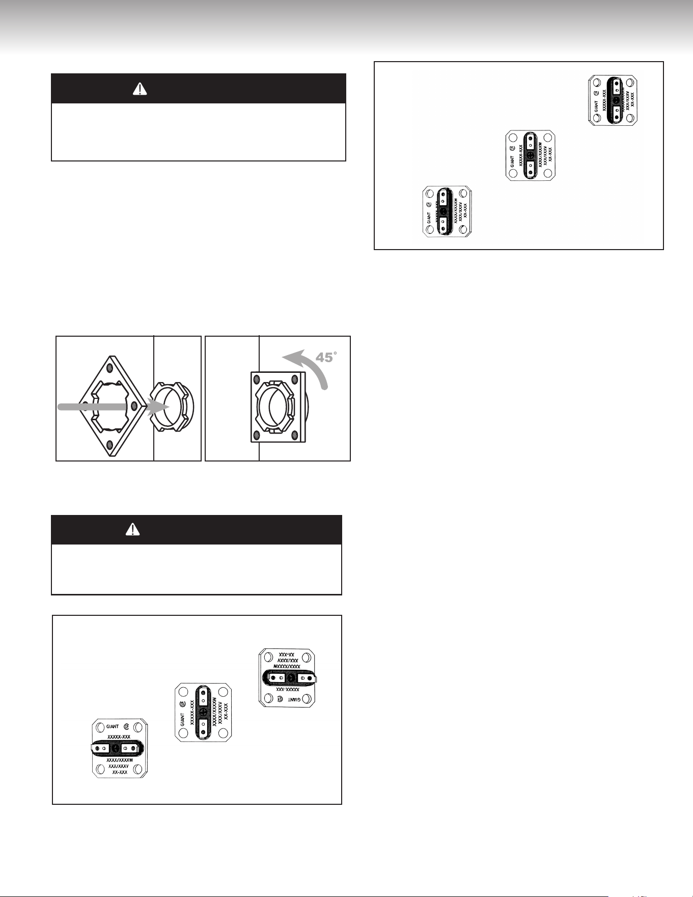
27
Table 4a
All 105 models, 1083-1086-1089 models, 1123-1126-1129 models
GENERAL MAINTENANCE
Element and Thermostat Replacement
DANGER
WARNING
CAUTION
AVERTISSEMENT
ATTENTION
Before attempting to repair or replace any of the electrical compo-
nents on this water heater, turn “OFF” the power to the water
heater. Failure to do so could result in electrical shock and/or prop-
erty damage, personal injury, or death.
Replacing an Element
1) Turn “OFF” the power to the water heater and drain all of the water
from the water heater (see Draining the Water Heater, page 28).
2) Open the elements and thermostat(s) access cover and remove
the insulation.
3) Disconnect the wires from the element terminals.
4) Unscrew the four (4) bolts securing the element to the water
heater and pull element out of the tank. Make sure the TWIST-
LOCK flange is in the right position (See Figure 28).
Figure 28 TWIST-LOCK
5) Replace the element with a new element of the same wattage and
voltage. Make sure that the gasket surface is clean and that the
element has been re-installed water-tight with a new gasket.
IMPORTANT
Make sure that the elements are properly oriented as illustrated
on the following figures. (Orientation of the text on the element
flange is important). (See Figures 29 and 30)
Figure 29
105 et 108 models
Figure 30
112 models
6) Re-connect the wires to the element and tighten securely.
7) Re-fill the water heater (see Filing the Water Heater, page 5).
DO NOT TURN THE POWER ON TO THE WATER HEATER
UNLESS YOU ARE SURE IT IS COMPLETELY FILLED WITH
WATER.
8) Replace the insulation and close the elements and thermostat(s)
access panel before turning “ON” the power to the water heater.
Replacing a Thermostat
(See Replacement Parts, page 29 to 33)
1) Turn “OFF” the power to the water heater.
2) Open the elements and thermostat(s) access panel and remove
the insulation.
3) Disconnect the wires from the thermostat terminals.
4) Lift the thermostat bracket arms and slide the thermostat up to
remove it.
5) Replace the thermostat with a new thermostat of the same manu-
facturer and type.
6) Reconnect the wires on the thermostat terminals referring to the
corresponding wiring diagram in Figures 11 to 24.
7) Set the thermostat to the desired temperature (see Water
Temperature Regulation, page 26).
8) Replace the insulation and close the elements and thermostat(s)
access panel before turning “ON” the power to the water heater.
Temperature and Pressure-Relief Valve
Manually operate the temperature and pressure-relief valve at
least once a year, standing clear of the outlet to avoid being
burned. Lift and release the operating lever on the valve to make
it operate freely. If, after manually operating the valve, it fails to
completely reset itself and continues to discharge water, replace it
with a new one.
Anodes
This water heater is equipped with two (2) magnesium anodes that
are designed to prolong the life of the glass-lined inner tank. The
anodes are slowly consumed, protecting the glass-lined tank from
corrosion. They should be checked every two (2) years. If more
than half of any anode has been consumed, it should be replaced.
Instructions on how to change an anode can be obtained from the
manufacturer.
28
GENERAL MAINTENANCE
The life expectancy of the water heater is reduced where a water
softener is introduced to fight hard water, because the sodium salts
added by a softener make this water extremely conductive. In these
conditions, the magnesium anodes are consumed more rapidly and
should be verified every year.
In certain water conditions, the magnesium anodes will react with
the water, producing discoloured or smelly water. The most
common complaint is hot water that smells like rotten eggs. This
phenomenon is the result of the reaction between the magnesium
anodes and hydrogen sulfide gas dissolved in the water, which
occurs frequently in well systems. This problem can usually be
eliminated or reduced by changing the anodes to a type more
suitable for these conditions (aluminum anodes) and by chlorinating
the water heater and the plumbing system. If the problem persists,
special filtration equipment may be required. Under no circumstances
are the anodes to be removed from the water heater on a
permanent basis. Removal of the anodes will lead to premature
failure of the water heater and void the warranty.
DANGER
WARNING
CAUTION
AVERTISSEMENT
ATTENTION
Hydrogen gas can be produced in a hot water system that has not
been used for a long period of time (generally two [2] weeks or
more). HYDROGEN GAS IS EXTREMELY FLAMMABLE. It is
highly recommended to open a hot water faucet for several minutes
before you use any electrical appliances connected to the hot water
system, such as a dishwasher or washing machine. If hydrogen gas
is present, there will be an unusual sound, such as air escaping
through the pipe, as the hot water faucet is opened. DO NOT smoke
or introduce an open flame near the faucet when it is opened.
Draining the Water Heater
Drain a pail of water through the drain valve at least once a year. This
will remove excess sediment from the bottom of the tank. This
sediment, if allowed to accumulate, will reduce the efficiency and the
life of the tank.
To completely drain the water heater:
1) Turn “OFF” the power to the water heater.
2) Close the cold water supply manual shut-off valve.
3) Connect one end of a garden hose to the water heater drain valve
and put the other end next to a free-flowing drain.
4) Open the drain valve by inserting a flat-head screwdriver into
the slot on the head of the drain valve and turning the knob
counterclockwise .
5) Open a hot water faucet to allow air into the system.
Vacation
If you are planning a vacation or other prolonged absence, it is
essential to turn “OFF” the power to the water heater and the cold
water supply to the water heater. This preventive action will save
energy, protect against property damage in the event the water
heater leaks, and prevent the build-up of hydrogen gas. If the water
heater and piping are exposed to freezing temperatures, they should
both be drained. Remember to check the water heater thoroughly
after it has been shut off for an extended period of time before putting
it back in operation. Make sure that the water heater is completely full
of water, and that the cold water supply manual shut-off valve is
open, before turning “ON” the power to the water heater.
Getting Service for your Water Heater
If you are having problems with your water heater, follow these three
easy steps:
1) Read the Troubleshooting Guide contained in this manual (see
Page 34). It lists the most common problems experienced with
your electric water heater. The solutions you find listed may
provide a quick and simple solution to your problem and save you
time and money.
2) If the solution listed in the Troubleshooting Guide does not solve
the problem or if your particular problem is not listed in the guide,
contact the installer of the water heater, or the local electric utility.
3) If you still cannot solve the problem, contact the manufacturer’s
Customer Service Department by e-mail at [email protected]
or by telephone at 1-800-363-9354 (option 1). To help serve you in
a quick and efficient manner, always have the following informa-
tion ready:
a) Model number.
b) Serial number.
c) Date of installation.
d) Where the water heater was purchased.
e) Complete address where the water heater is installed.
f) A description of the problem.
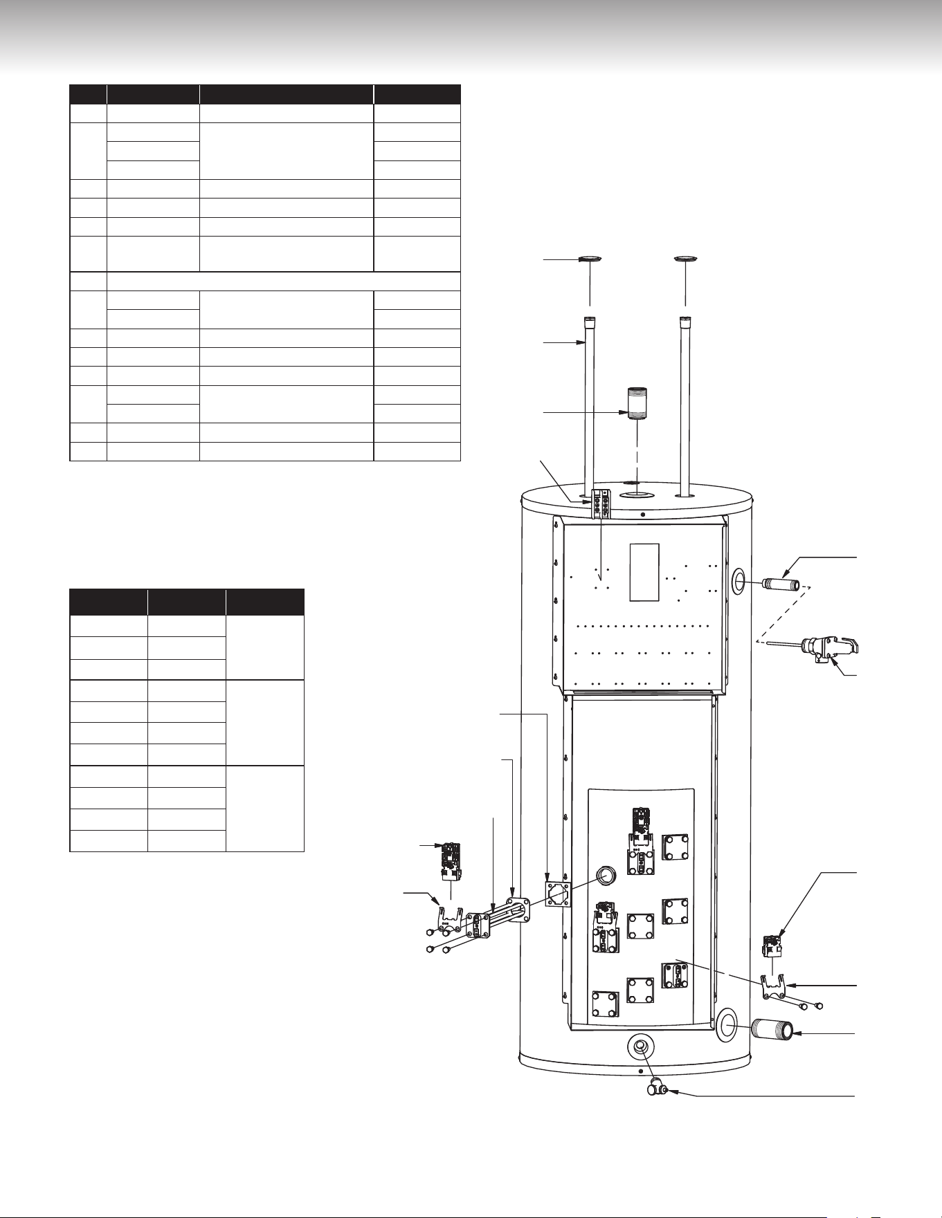
29
REPLACEMENT PARTS
1
2
3
4
5
6
7
8
9
10
11
9
12
13
14
Item Part number Description Models
1 87000014-A Snap-in plug All
2
MS155410
Magnesium anodes
105
MS155520 108
MS166530 112
3 16000008-A Outlet nipple 1½” X 3” All
4 TB587001 Terminal block All
5 99001204-A Twist-lock ange with screws All
6 18G0002
Square ange element
gasket
All
7 SEE ELEMENT TABLE BELOW
8
56000016-A
Combination thermostat
/ high limit
105
56000035-A 108 & 112
9 18G0001 Thermostat bracket All
10 DV3Z0070 Brass drain valve All
11 16001402-A Inlet nipple 1½’’ X 4” All
12
56000018-A
Lower thermostat
105
56000034-A 108 & 112
13 SV0N3020 T&P relief valve All
14 16000015-A Relief nipple ¾” X 3½’’ All
Illustration shows Model 108 with 4 elements
Part # Watts Volts
9AG30/80 3,000W
208V
9AG45/80 4,500W
9AG50/90 5,000W
10G30/80 3,000W
240V
10G45/80 4,500W
10G50/90 5,000W
10G60/100 6,000W
13G30/80 3,000W
480V
13G45/80 4,500W
13G50/90 5,000W
13G60/100 6,000W
ELEMENT TABLE
208 Volts, 240 Volts, 480 Volts
105, 108 & 112 models
with 2 or 4 elements
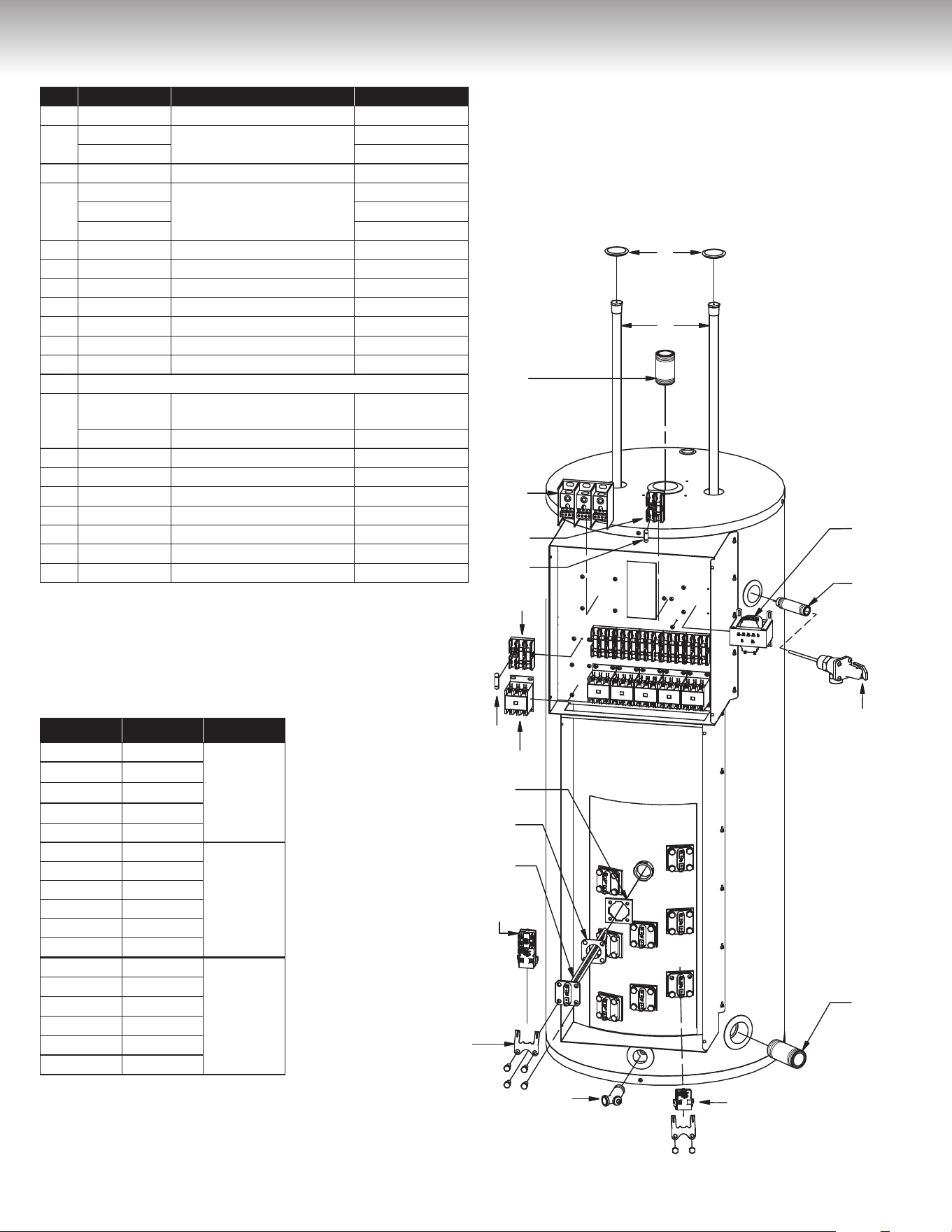
30
REPLACEMENT PARTS
19
18
17
16
10
11
12
13
14
3
4
6
5
7
8
9
20
15
1
2
Item Part number Description Models
1 87000014-A Snap-in plug All
2
MS155410
Magnesium anodes
105
MS155520 108
3 16000008-A Outlet nipple 1½” X 3” All
4
32000008-A
Terminal block three phases
3 elements
32000007-A 6 elements
32000009-A 9 elements
5 34001005-A Fuse Holder (2P) All
6 34000003-A Fuses (3 amps Class G) All
7 34001004-A Fuse Holders (3P) *US models (-US)
8 34000004-A Fuses (30 amps Class G) *US models
9 43000008-A Contactors HCC-3XT02CY All
10 99001204-A Twist-lock ange with screws All
11 18G0002 Square ange element gasket All
12 SEE ELEMENT TABLE BELOW
13
56000016-A
Combination
thermostat / high limit
All except 1053 &
1083
56000022-A High limit 1053 & 1083
14 18G0001 Thermostat bracket All
15 DV3Z0070 Brass drain valve All
16 56000018-A Lower thermostat 1053 & 1083
17 16001402-A Inlet nipple 1½’’ X 4” All
18 SV0N3020 T&P relief valve All
19 16000015-A Relief nipple ¾” X 3½’’ All
20 44000004-A Transformer Multi-tap /120V All
* Optional for Canadian Models
208 Volts, 240 Volts, 480 Volts
105, 108 models
with 3, 6, or 9 elements
Illustration shows Model 108 with 9 elements
ELEMENT TABLE
Part # Watts Volts
9AG20/80 2,000W
208V
9AG30/80 3,000W
9AG40/80 4,000W
9AG45/80 4,500W
9AG50/90 5,000W
10G20/80 2,000W
240V
10G30/80 3,000W
10G40/80 4,000W
10G45/80 4,500W
10G50/90 5,000W
10G60/100 6,000W
13G20/80 2,000W
480V
13G30/80 3,000W
13G40/80 4,000W
13G45/80 4,500W
13G50/90 5,000W
13G60/100 6,000W
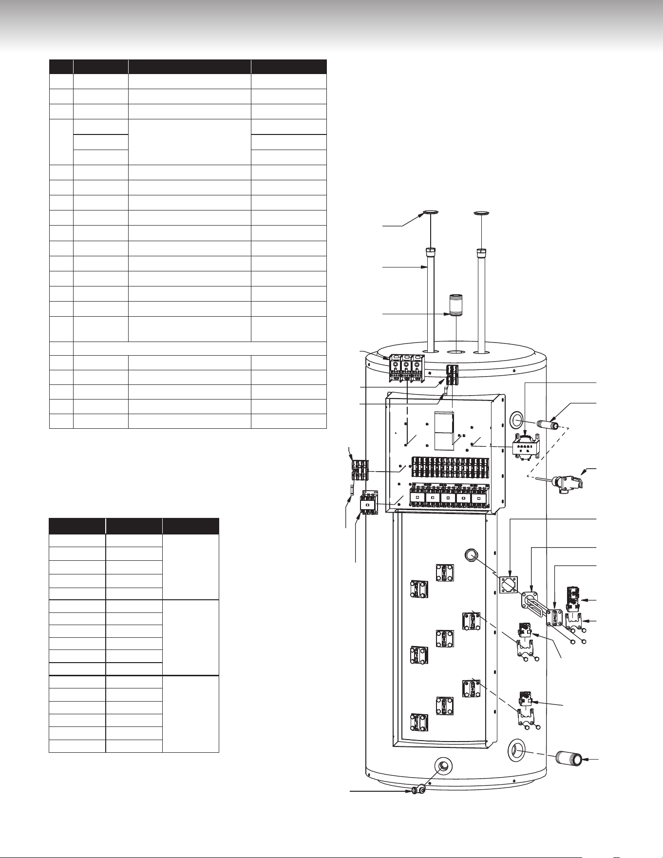
31
REPLACEMENT PARTS
2
3
19
20
4
5
6
7
8
9
10
21
17
18
16
15
14
13
12
11
1
* Optional for Canadian Models
Illustration shows Model 112 with 9 elements
208 Volts, 240 Volts, 480 Volts
112 model
with 3, 6, or 9 elements
Item Part number Description Models
1 87000014-A Snap-in plug All
2 MS166530 Magnesium anodes 112
3 16000008-A Outlet nipple
1½” X 3”
All
4
32000008-A
Terminal block
three phases
All 3 elements
32000007-A All 6 elements
32000009-A All 9 elements
5 34001005-A Fuse Holder (2P) All
6 34000003-A
Fuses (3 amps Class G)
All
7 34001004-A Fuse Holders (3P) *US models (-US)
8 34000004-A
Fuses (30 amps Class G)
*US models
9 43000008-A Contactors HCC-3XT02CY All
10 DV3Z0070 Brass drain valve All
11 16001402-A Inlet nipple
1½’’ X 4”
All
12 56000018-A Lower thermostat All except 1123
13 56000018-A Middle thermostat 1129 only
14 18G0001 Thermostat bracket All
15 56000016-A
Combination
thermostat / high limit
1126, 1129 top,
1123 bottom
16 SEE ELEMENT TABLE BELOW
17 18G0002 Square ange element gasket All
18 99001204-A Twist-lock ange with screws All
19 SV0N3020 T&P relief valve All
20 16000015-A Relief nipple
¾” X 3½’’
All
21 44000004-A Transformer Multi-tap /120V All
ELEMENT TABLE
Part # Watts Volts
9AG20/80 2,000W
208V
9AG30/80 3,000W
9AG40/80 4,000W
9AG45/80 4,500W
9AG50/90 5,000W
10G20/80 2,000W
240V
10G30/80 3,000W
10G40/80 4,000W
10G45/80 4,500W
10G50/90 5,000W
10G60/100 6,000W
13G20/80 2,000W
480V
13G30/80 3,000W
13G40/80 4,000W
13G45/80 4,500W
13G50/90 5,000W
13G60/100 6,000W
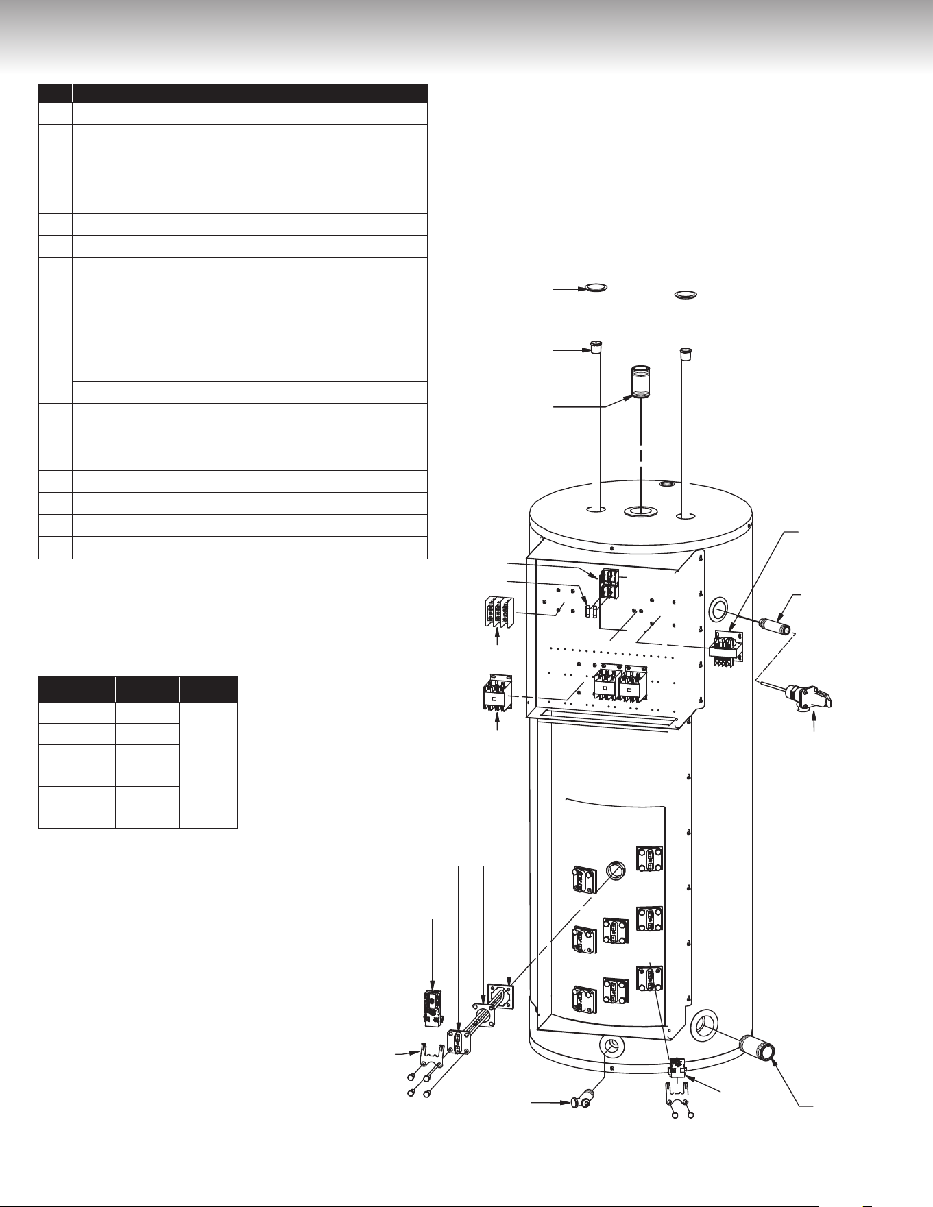
32
REPLACEMENT PARTS
1
2
3
4
7
6
5
8910
11
12
13
14
15
16
17
18
Illustration shows Model 108 with 9 elements
600 Volts
105, 108 models
with 3, 6, or 9 elements
Part # Watts Volts
12G20/80 2,000W
347V
12G30/80 3,000W
12G40/80 4,000W
12G45/80 4,500W
12G50/90 5,000W
12G60/100 6,000W
ELEMENT TABLE
Item Part number Description Models
1 87000014-A Snap-in plug All
2
MS155410
Magnesium anodes
105
MS155520 108
3 16000008-A Outlet nipple 1½’’ X 3’’ All
4 34001005-A Fuse Holder (2P) All
5 34000003-A Fuses (3 amps Class G) All
6 32000006-A Terminal block three phases All
7 CM586000 Contactors HCC-3XU02CY All
8 99001204-A Twist-lock ange with screws All
9 18G0002 Square ange element gasket All
10 SEE ELEMENT TABLE BELOW
11
56000016-A
Combination
thermostat / high limit
All except
1053,1083
56000022-A High limit 1053, 1083
12 18G0001 Thermostat bracket All
13 DV3Z0070 Brass drain valve All
14 56000018-A Lower thermostat 1053, 1083
15 16001402-A Inlet nipple 1½’’ X 4’’ All
16 SV0N3020 T&P relief valve All
17 16000015-A Relief nipple ¾’’ X 3½’’ All
18 TF485000 Transformer 600/240V All
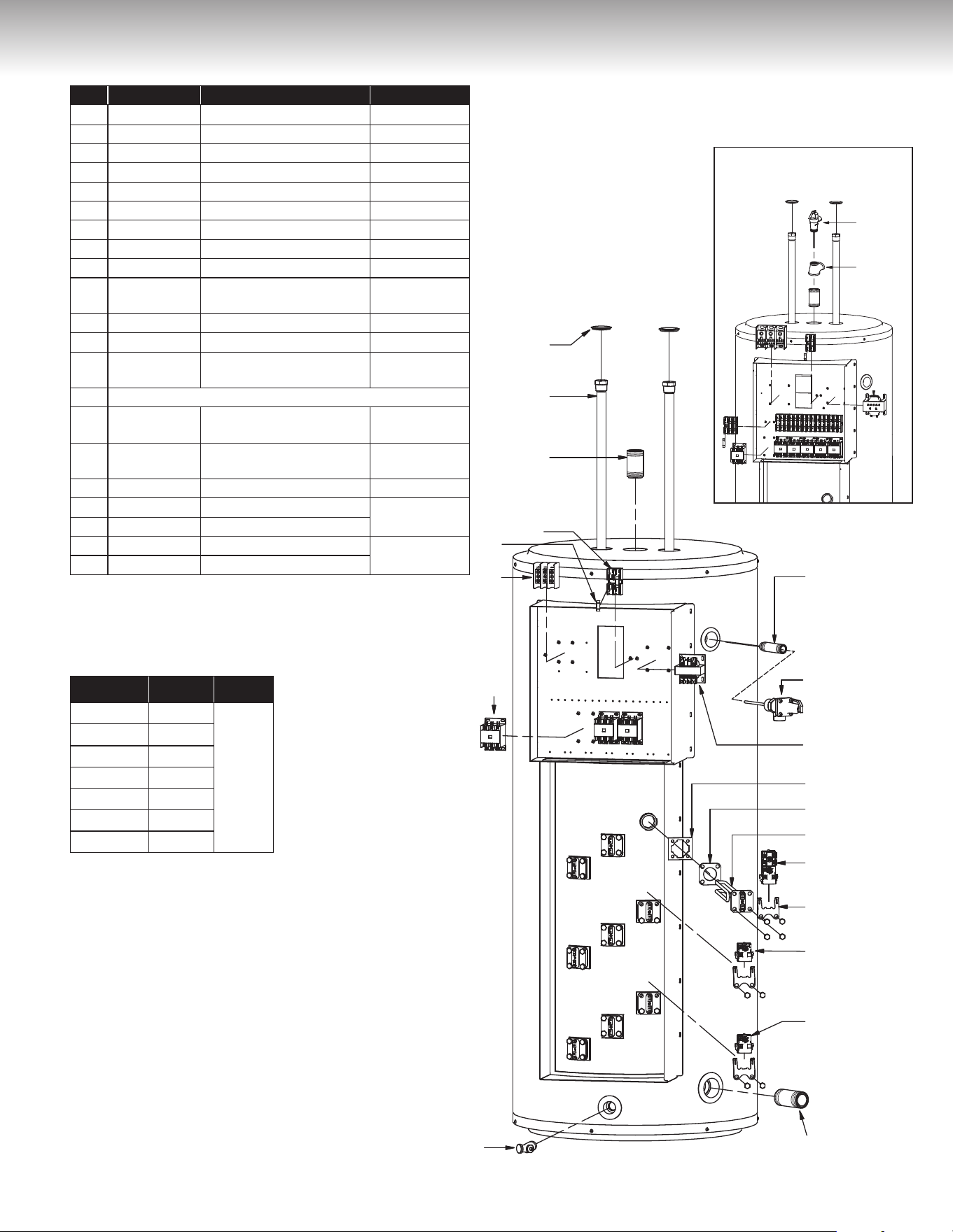
33
Illustration shows Model 112 with 9 elements
REPLACEMENT PARTS
2
3
4
5
6
7
8
18
19
16
15
14
13
12
11
9
17
10
1
Item Part number Description Models
1 87000014-A Snap-in plug All
2 MS166530 Magnesium anodes 112
3 16000008-A Outlet nipple 1½” X 3” All
4 34001005-A Fuse Holder (2P) All
5 34000003-A Fuses (3 amps Class G) All
6 TB587000 Terminal block three phases All
7 CU586000 Contactors HCC-3XU02CY All
8 DV3Z0070 Brass drain valve All
9 16001402-A Inlet nipple 1½’’ X 4” All
10 56000018-A Lower thermostat
All except
1123
11 56000018-A Middle thermostat 1129 only
12 18G0001 Thermostat bracket All
13 56000016-A
Combination
thermostat / high limit
1126, 1129 top
1123 bottom
14 SEE ELEMENT TABLE BELOW
15 18G0002
Square ange
element gasket
All
16 990012040A
Twist-Lock ange
with screws
All
17 TF485000 Transformer 600/240V All
18 SV0N3020 T&P relief valve
All except
63kW
19 16000015-A Relief nipple ¾” X 3½’’
20 17000017-A T&P relief valve
63kW model
only
21 90000006-A Brass Tee
1 ½’’ X 1 ½’’ X 1’’
600 Volts
112 model
with 3, 6, or 9 elements
Part # Watts Volts
12G20/80 2,000W
347V
12G30/80 3,000W
12G40/80 4,000W
12G45/80 4,500W
12G50/90 5,000W
12G60/100 6,000W
12G70/80 7,000W
ELEMENT TABLE
20
21
112/600V at 63kW model

34
TROUBLESHOOTING GUIDE
CONDITION CAUSE REMEDY
No hot water.
Dry-fired element. Replace with new element.
Main power supply is “OFF”. Turn “ON” main power supply.
Burnt fuse. Replace with new fuse.
Circuit breaker has tripped. Reset circuit breaker.
High limit reset control has tripped. Reset high limit control by pushing
the reset button.
Circuit breaker is defective. Replace with new circuit breaker.
Defective thermostat. Replace with new thermostat.
Defective element. Replace with new element.
Not enough hot water.
Water heater is undersized. Install size of water heater that meets demand.
High hot water demand. Increase the temperature of the thermostat.
Very cold water supply. Increase the temperature of the thermostat.
Wrong piping connections. Correct piping.
Sediment or lime accumulation at bottom
of water heater.
Drain water heater. Check to see if water treatment
is necessary.
Hot water plumbing system leaks. Check hot water plumbing system for leaks and repair.
Thermostat adjusted too low. Increase the temperature of the thermostat.
Defective thermostat. Replace with new thermostat.
Defective element. Replace with new element.
Long runs or exposed piping. Insulate piping.
Hot water piping on outside wall. Insulate piping.
Boiling hot water.
Thermostat temperature set too high. Lower the temperature on the thermostat.
Thermostat not in contact with water heater.Position properly. Be sure insulation is not
interfering with thermostat.
Element attacked by CO
2
. Replace with new element.
Defective thermostat. Replace with new thermostat.
Continuous operation.
Water heater is undersized. Install size of water heater that meets demand.
Element wattage too small. See Conversion Guide.
Thermostat not in contact with water heater.Position properly. Be sure insulation is not
interfering with thermostat.
Thermostat temperature set too low. Increase the temperature of the thermostat.
Defective thermostat. Replace with new thermostat.
Defective high limit reset control. Replace with new high limit reset control.
Element failure.
Wiring connections are wrong. See Figures 11 to 24 for correct wiring.
Wiring connections are loose. Locate, clean carefully, reconnect properly.
Lightning/Power surge. Inspect/replace fuse, element, and thermostat.
High voltage. Check with electrical utility and correct.
Short circuit. Locate short circuit and repair.
Thermostat failure.
No power. Inspect fuse/circuit breaker, replace/reset.
Loose wiring connection. Locate, clean carefully, reconnect properly.
Lightning/Power surge. Inspect/replace fuse, element, and thermostat.
Low/High voltage. Check with electrical utility and correct.
Short circuit. Locate short circuit and repair.
Blown fuse/circuit breaker.
Wiring connections are wrong. See Figures 11 to 24 for correct wiring.
Wiring connections are loose. Locate, clean carefully, reconnect properly.
Lightning/Power surge. Inspect/replace fuse, element, and thermostat.
High voltage. Check with electrical utility and correct.
Short circuit. Locate short circuit and repair.
Power supply wiring undersized.
See Table 1 and consult electrical code for correct wire size.
Fuse burns instantly. Short-circuit. Locate short circuit and repair.
Fuse burns often.
Fuse contacts oxidized or fuse not screwed
in tight enough.
Clean contacts and tighten fuse.
Power supply wiring is undersized.
See Table 1 and consult electrical code for correct wire size
.
CONDITION CAUSE REMEDY

35
CONDITION CAUSE REMEDY
No hot water.
Dry-fired element. Replace with new element.
Main power supply is “OFF”. Turn “ON” main power supply.
Burnt fuse. Replace with new fuse.
Circuit breaker has tripped. Reset circuit breaker.
High limit reset control has tripped. Reset high limit control by pushing
the reset button.
Circuit breaker is defective. Replace with new circuit breaker.
Defective thermostat. Replace with new thermostat.
Defective element. Replace with new element.
Not enough hot water.
Water heater is undersized. Install size of water heater that meets demand.
High hot water demand. Increase the temperature of the thermostat.
Very cold water supply. Increase the temperature of the thermostat.
Wrong piping connections. Correct piping.
Sediment or lime accumulation at bottom
of water heater.
Drain water heater. Check to see if water treatment
is necessary.
Hot water plumbing system leaks. Check hot water plumbing system for leaks and repair.
Thermostat adjusted too low. Increase the temperature of the thermostat.
Defective thermostat. Replace with new thermostat.
Defective element. Replace with new element.
Long runs or exposed piping. Insulate piping.
Hot water piping on outside wall. Insulate piping.
Boiling hot water.
Thermostat temperature set too high. Lower the temperature on the thermostat.
Thermostat not in contact with water heater.Position properly. Be sure insulation is not
interfering with thermostat.
Element attacked by CO
2
. Replace with new element.
Defective thermostat. Replace with new thermostat.
Continuous operation.
Water heater is undersized. Install size of water heater that meets demand.
Element wattage too small. See Conversion Guide.
Thermostat not in contact with water heater.Position properly. Be sure insulation is not
interfering with thermostat.
Thermostat temperature set too low. Increase the temperature of the thermostat.
Defective thermostat. Replace with new thermostat.
Defective high limit reset control. Replace with new high limit reset control.
Element failure.
Wiring connections are wrong. See Figures 11 to 24 for correct wiring.
Wiring connections are loose. Locate, clean carefully, reconnect properly.
Lightning/Power surge. Inspect/replace fuse, element, and thermostat.
High voltage. Check with electrical utility and correct.
Short circuit. Locate short circuit and repair.
Thermostat failure.
No power. Inspect fuse/circuit breaker, replace/reset.
Loose wiring connection. Locate, clean carefully, reconnect properly.
Lightning/Power surge. Inspect/replace fuse, element, and thermostat.
Low/High voltage. Check with electrical utility and correct.
Short circuit. Locate short circuit and repair.
Blown fuse/circuit breaker.
Wiring connections are wrong. See Figures 11 to 24 for correct wiring.
Wiring connections are loose. Locate, clean carefully, reconnect properly.
Lightning/Power surge. Inspect/replace fuse, element, and thermostat.
High voltage. Check with electrical utility and correct.
Short circuit. Locate short circuit and repair.
Power supply wiring undersized.
See Table 1 and consult electrical code for correct wire size.
Fuse burns instantly. Short-circuit. Locate short circuit and repair.
Fuse burns often.
Fuse contacts oxidized or fuse not screwed
in tight enough.
Clean contacts and tighten fuse.
Power supply wiring is undersized.
See Table 1 and consult electrical code for correct wire size
.
CONDITION CAUSE REMEDY
TROUBLESHOOTING GUIDE
Smoking wiring.
Lightning/Power surge. Inspect/replace fuse, element, and thermostat.
Low/High voltage. Check with electrical utility and correct.
Power supply wiring undersized.
See Table 1 and consult electrical code for correct wire size
.
Service wires charred or hot.
Wiring connections are wrong. See Figures 11 to 24 for correct wiring.
Water heater not properly grounded. Properly ground the water heater.
Lightning/Power surge. Inspect/replace fuse, element, and thermostat.
High voltage. Check with electrical utility and correct.
Short circuit. Locate short circuit and repair.
Power supply wiring undersized.
See Table 1 and consult electrical code for correct wire size.
Drain valve leaks.
Drain valve is open. Close the drain valve.
Defective drain valve. Replace with new drain valve.
Water drips from the
relief valve.
Excessive water pressure. Install a pressure-reducing valve.
Thermal expansion in a closed water
system.
Install a suitable expansion tank on the cold water
supply line.
Improperly seated relief valve. Check relief valve works properly and replace, if neces-
sary.
Defective thermostat. Replace with new thermostat.
Defective relief valve. Replace with new relief valve.
Water on the floor/drain pan.
Water discharge from the relief valve. See Pressure build-up in a water system.
Element leaks. Replace with new element and gasket.
Water heater leaks. Replace with new water heater.
Wet insulation.
Leaking plumbing connections. Locate leak and repair.
Leaking around heating element. Tighten, clean, and smooth face of tank flange and replace
element gasket.
Water discharge from the relief valve. See Pressure build-up in a water system.
Singing element. Build up of mineral deposits on element. Clean element, replace with new element if necessary.
Singing thermostat.
Thermostat not flush with tank. Install thermostat properly.
Wiring connections are loose. Locate, clean carefully, reconnect properly.
Traces of rust in the hot water.
Anode rods has been eaten away. Replace new anode rods.
Rusty water. Water corrosion. Replace with new water heater.
Rotten egg smell. High sulfate or mineral content in water. Change magnesium anodes to an aluminum anodes and
bleach water heater.
Tank bulged.
No relief valve installed. Install proper relief valve.
Excessive water pressure. Install a pressure-reducing valve.
Thermal expansion in a closed water
system.
Install a suitable expansion tank on the cold water supply
line.
“Water hammer” Install anti-water hammers suitably selected and installed
according to the manufacturer’s instructions

STANDARD BASIC LIMITED WARRANTY
ON COMMERCIAL WATER HEATERS
(Hereunder referred to as “Unit” or “Equipment”)
GENERAL
The manufacturer warrants that, subject to verification of your warranty
claim within the warranty period described below, the necessary corrective
actions will be taken to either repair or replace the defective unit or
component part subject to the terms and conditions outlined in this
document. Furthermore, any replacement unit or component part supplied
under warranty will carry only the warranty remaining portion, based on
the original unit installation date. However, the warranty is limited to ONE
(1) replacement unit. If due to some unusual circumstance, a replacement
unit or component part is found to be defective by our inspection
department, another unit or component part will be provided in order to
fulfill the obligation of the original warranty. This warranty applies only to
the original owner that purchased the unit, to the unit original installation
location, and it is not transferable. In order to benefit from this warranty,
the warranty reply card must be completed and sent back to GIANT within
forty-five (45) days of the unit purchase date, otherwise the warranty will
be three (3) years from the date of manufacture, without exception.
THE INNER TANK
If the inner tank of a water heater leaks in the shortest period of THREE
(3) years from the date of installation or FIFTY-FOUR (54) months
from the date of manufacture, whichever comes first, a replacement
will be provided to the original owner who purchased it. If an identical
replacement model of the original model is not available, for any reason
whatsoever, the manufacturer reserves the right to offer a comparable
model, however, a surcharge will be applied for all component (s) which
will have been incorporated into the water heater. Use of equipment for
any purpose other than drinking water will void the warranty.
COMPONENT PARTS
If any component part is found to be defective within ONE (1) year from
the date of original installation, provided said defective part is an in-house
factory made piece or an original factory approved OEM piece, the
manufacturer will furnish a replacement part after the receipt and testing
of the part claimed to be defective.
THIS WARRANTY WILL NOT APPLY:
1) To defects or malfunctions resulting from failure to properly install,
operate, or maintain the unit in accordance with the Owner’s
Manual.
2) If the installation does not conform to CSA &/or ETL Standards as
well as any applicable national or local building codes.
3) To any damage or failure caused by abuse, fire, floods, freezing,
or other acts of God.
4) To any damage or failure caused by operating the unit without
an approved temperature & pressure-relief valve having been
installed.
5) To any damage or failure caused by powering any energy source
while the equipment is empty or partially empty or contains
sediment build-up resulting in dry firing of the heating elements.
6) To any damage or failure caused by connecting the unit to any
other source of energy not approved by GIANT or by operating
the equipment for other use than with potable water without any
additives such as salt, chlorine, or chemicals other than those
added for the purpose of rendering the water fit to drink.
7) To any damage or failure caused by the removal of the anode
and/or by not assuring that there is a working anode in the unit at
all times. ‘‘All anodes must be checked at least once every
two (2) years & replaced, if necessary’’.
8) To any damage or failure caused by the use of the unit with a
water softener if the magnesium anode has not been replaced by
an aluminum anode approved by Giant, as well as the addition of
zinc pellets.
9) To any damage or failure caused by having affixed to the unit any
non-factory made or factory approved replacement part(s), such
as elements, controls, dip-tubes, anode, induced-current anode,
relief valves, etc.
10) To any damage caused by not having the unit installed adjacent
to a free-flowing drain or in a pan or basin connected to such
free-flowing drain.
11) For all equipment operated at water temperatures exceeding the
maximum operating setting of the thermostat and/or the high limit
control, at a pressure exceeding the one listed on the rating plate,
for equipment subject to a water-hammer effect that reverses
the bottom of the tank, units that are installed in a closed-looped
system without any adequate expansion tank
1
being installed as
well as equipment installed in a system equipped with a backflow
preventer, a pressure-reducing valve, or any other device, such
as a check valve, without an adequate expansion tank being
installed.
1
Or any other method accepted by the competent authority.
12) To any unit drained for wintering purposes.
13) To any performance issue caused by the poor selection of
equipment, power supply, wiring, or fuse / breaker.
14) To any unit from which the rating plate has been removed or
altered.
15) To any break or damage caused by a water-hammer effect
coming from, but not limited to, a quick-closing valve, a solenoid
valve, or any other valves without an adequate pre-fabricated
expansion tank being installed in compliance with existing codes,
standards, and good practices.
16) To any issue caused by the installation of water connections
not compatible with the equipment input and output ‘‘NPT’’
connections.
17) To any unit installed outside of Canada or the United States.
SERVICE LABOUR RESPONSIBILITY
This warranty does not cover any labour expense for diagnostic, service,
removal, or re-installation of a replacement unit. All such expenses are the
responsibility of the unit owner.
SHIPPING COSTS
If a unit or component part is deemed to be replaced, the manufacturer
will pay the transportation costs to ship said replacement unit or part to a
convenient authorized distributor or retailer of our choice. The unit owner
must pay for any local cartage including the cost of returning the replaced
unit or component part to the authorized distributor or retailer.
CLAIM PROCEDURE
Any claim covered by the warranty must be made to GIANT within a
maximum of thirty (30) days from the date the defect is first discovered.
Failure to provide a written notice for such defect to the manufacturer
within the allocated time frame will void the warranty. Any claim for
warranty service should be made with your contractor, wholesaler, or
retailer from whom the unit was purchased. In turn, said contractor,
wholesaler, or retailer will contact the manufacturer. If this procedure
cannot be followed, please contact a local contractor, wholesaler,
or retailer distributing our products. For further warranty information,
please call our customer service department at (514) 645-8893 or
1-800-363-9354, option 1. In order to answer your call promptly, prior to
calling the factory, please make sure to have handy the unit model and
serial number that is found on the rating plate, on the side of the unit. Proof
of purchase showing the date and name of the business from whom the
unit was purchased is mandatory if the manufacturing date goes beyond
the warranty period offered by the manufacturer.
If an exact replacement unit is unavailable for whatever reason such as,
but not limited to, changes in government standards, the manufacturer
agrees to provide a unit or component part with comparable features. If
government regulations or industry standards require the replacement
unit or component part to have features not found on the defective unit
or component part, the unit owner will be charged the difference in price
associated with these required features. If such owner pays the difference
in price for these required features, they will benefit from a complete new
Standard Basic Limited Warranty for the replacement unit.
MISCELLANEOUS
No one is authorized to modify any conditions of this actual warranty.
The manufacturer will not honour any other warranty of any kind other
than what is offered. No claims for incidental or consequential damage
(including damage from leakage) will be accepted. If the warranty card
is not returned to us, a proof of purchase showing the name, date, and
location of the original point of purchase is mandatory to process any
warranty claim. Failure to provide such documentation will result in the
lesser of the warranty periods being offered, as stated in the ‘‘GENERAL’’
section. In order to avoid any confusion and/or disputes, we
suggest that the warranty card be completed and returned to us
no later than forty-five (45) days after installation.
© 2024 A. O. Smith Enterprises Ltd. 11021, Notre-Dame E. Street, Montréal-East, Québec, Canada H1B 5H3 54000089 GI-PM026En-1224