Version: OPS-PV-100W-V1.0
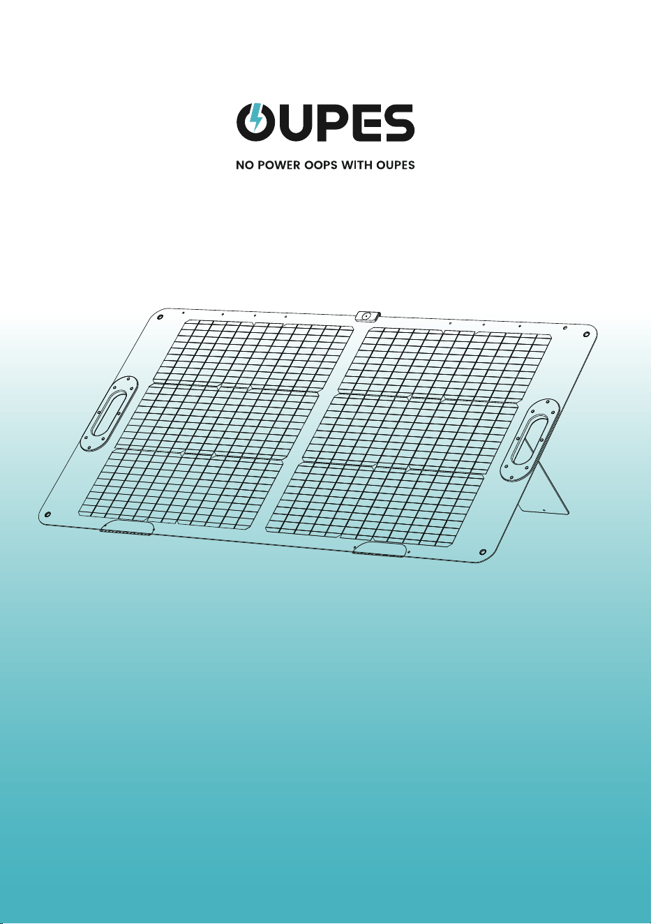
User Manual
100W Solar Panel

Customer service
Email us: [email protected]
Call us: +1(209)400-9909
Website: oupes.com
US Region
Email us: [email protected]
Website: eu.oupes.com
European Union Region
Email us: [email protected]
Website: ca.oupes.com
Canada Region
Email us: [email protected]
Website: mx.oupes.com
Mexico Region
Email us: [email protected]
Website: uk.oupes.com
United Kingdom Region

Disclaimer
Product List
Product Description
Specifications
Product Description
Instructions for Use
Connection Method
Calculation Method
In Series
In Parallel
01
03-04
02
03
04
05
06
07
08
07-08
English Contents
Language
English Contents
Deutsch (Deutsches Inhaltsverzeichnis)
French (Table des matières en français)
Italian (Indice in italiano)
Spanish (Tabla de Contenido en Español)
01-08
09-17
18-26
27-35
36-44

Disclaimer
Before using this product, please read this user manual carefully to ensure that you
fully understand the product and can use it correctly. After reading this user
manual, please keep it in a safe place for future reference. Improper use of this
product may cause serious injury to yourself or others, or result in product damage
and property loss. By using this product, you are deemed to have understood,
recognized and accepted all the terms and contents of this document. The Com-
pany shall not be responsible for any damages caused by the user's failure to use
this product in accordance with this user manual.
In accordance with laws and regulations, the company reserves the right of final
interpretation of this document and all documents related to this product. This
document is subject to change, update, revision or termination without notice.
Please visit our website for the latest product information.
●The company shall not be held responsible for any damage caused by force
majeure(e.g. fire, typhoon, flood, earthquake) or use under other abnormal circum-
stances by the customer.
●The company bears no responsibility for loss caused by the use of non-standard
connectors.
●The company shall not be liable for any damage caused by non-compliance
with the standard operation.
●Please do not disassemble the product. Otherwise, the warranty will be voided.
01
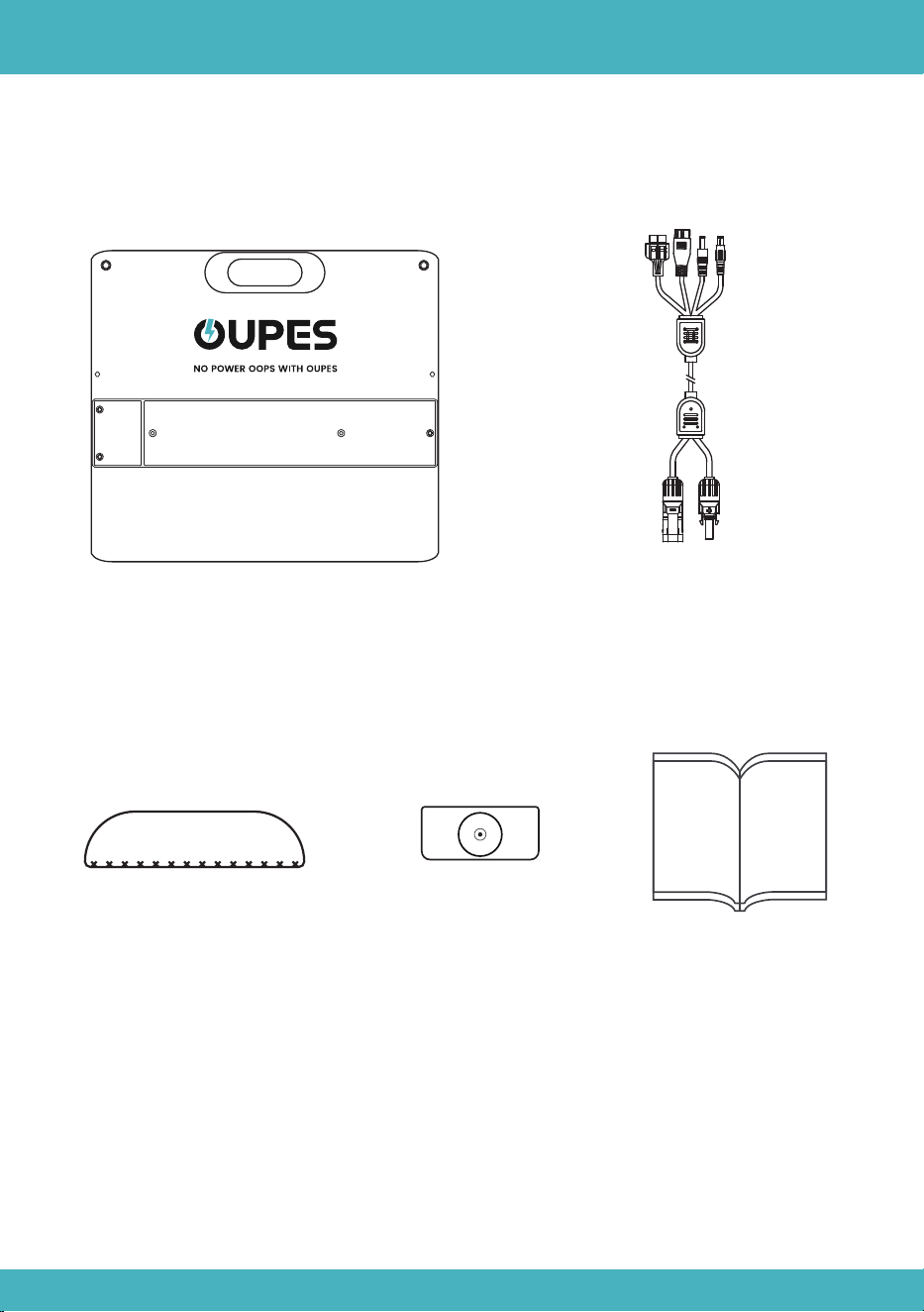
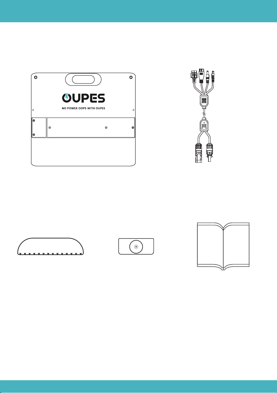
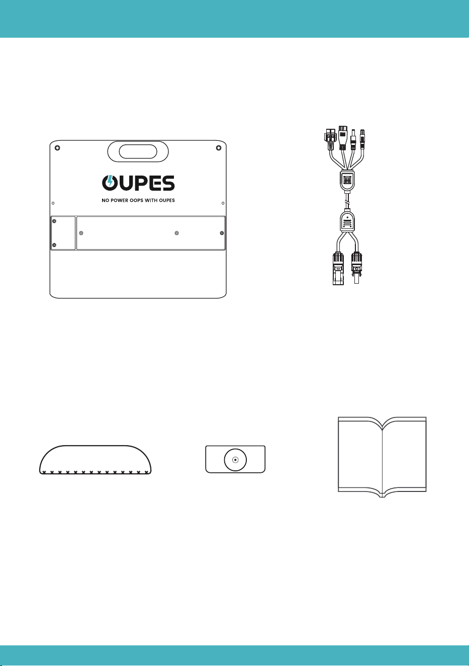
Solar Panel*1
Sundial Indicator*1
Product List
User Manual*1
02
MC4 connectors to Anderson+
XT60+7909+5521 Extension Cable
Water-proof Base*2
Product Description
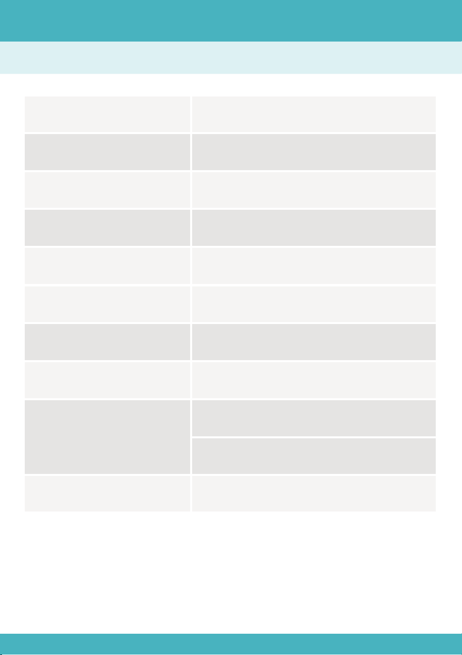
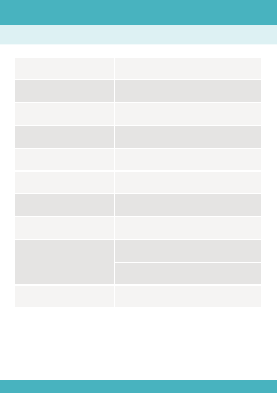
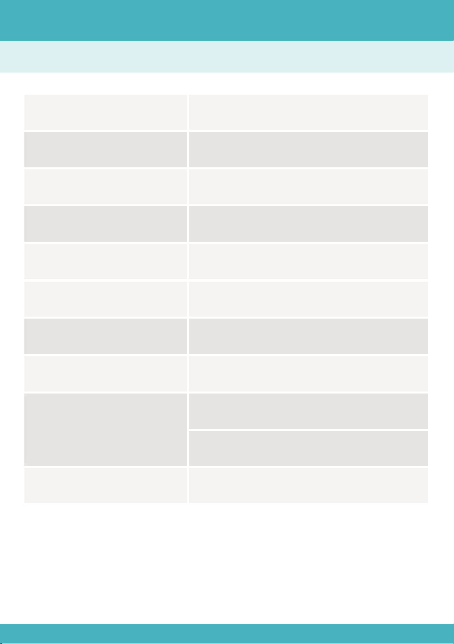
Rated Power
Cell Efficiency
Open Circuit Voltage
Short Circuit Current
100W
23%
24.4V
5.27A
Maximum Operating Voltage 20.5V
Maximum Operating Current
IP Grade
Working Temperature
4.88A
IP65
-4℉~185℉(-20℃~85℃)
Net Weight
9.92lb(4.5kg)
Dimension
Folded: 21.85*23.23*1.97in(555*590*50mm)
Unfolded: 43.7*23.23*1.38in(1110*590*35mm)
Specifications
03
Product Description
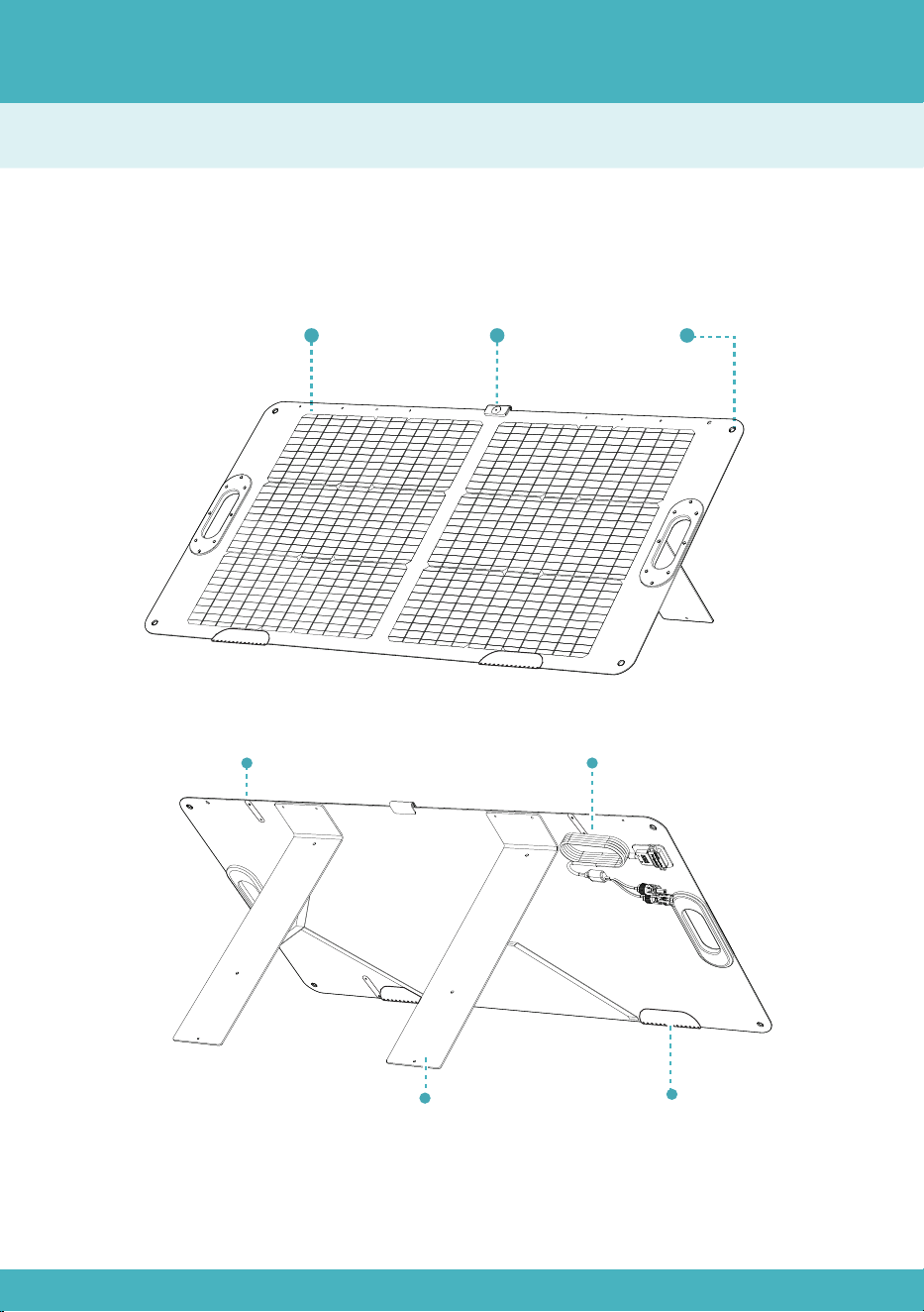
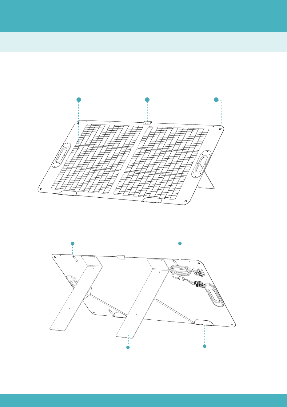
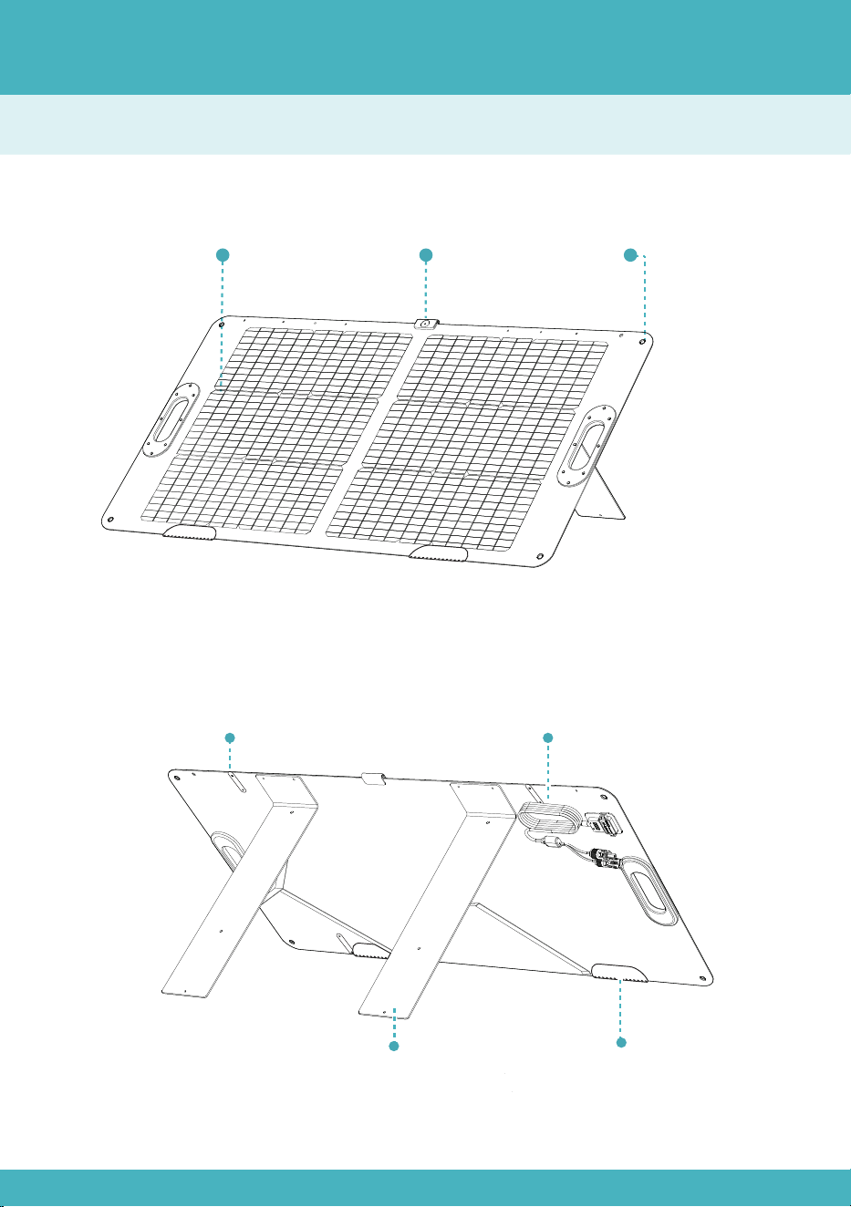
Overview
Mounting
Hole
Sundial Indicator
(Detachable)
Photovoltaic
Module
04
Bracket
MC4 Connectors Cables
Water-proof Base
Button Strap
Instructions for Use
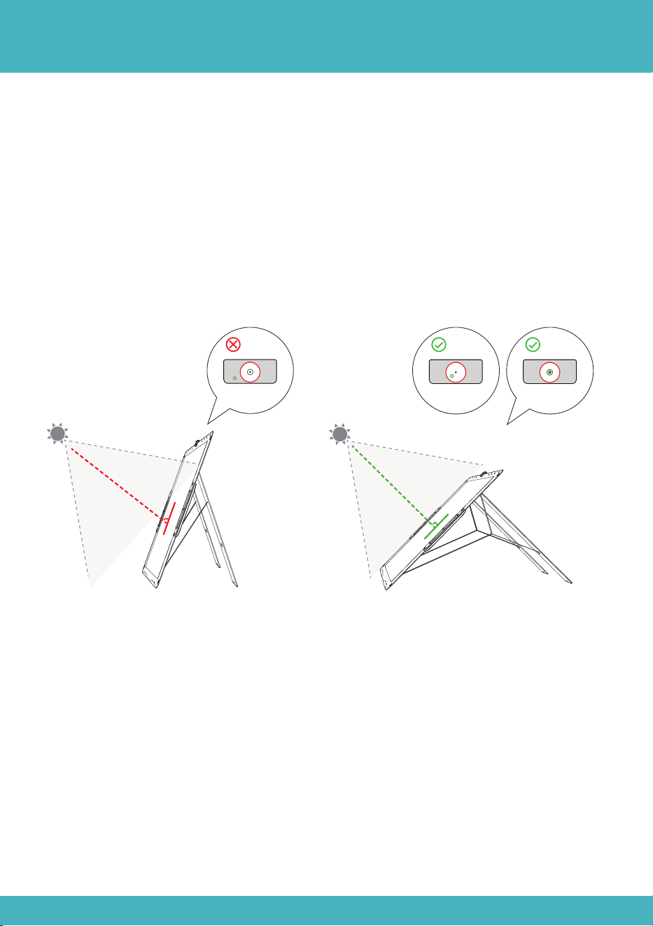
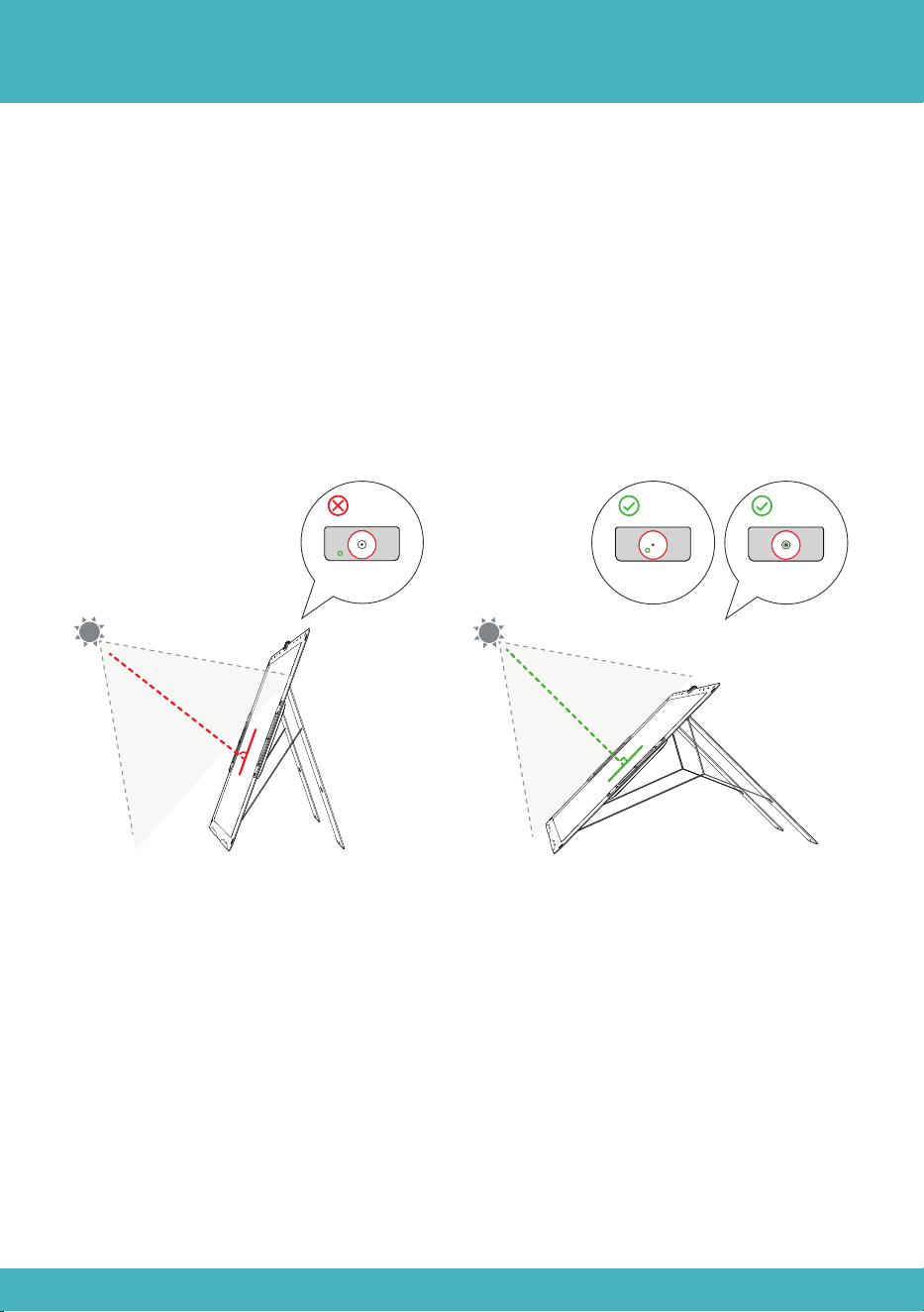
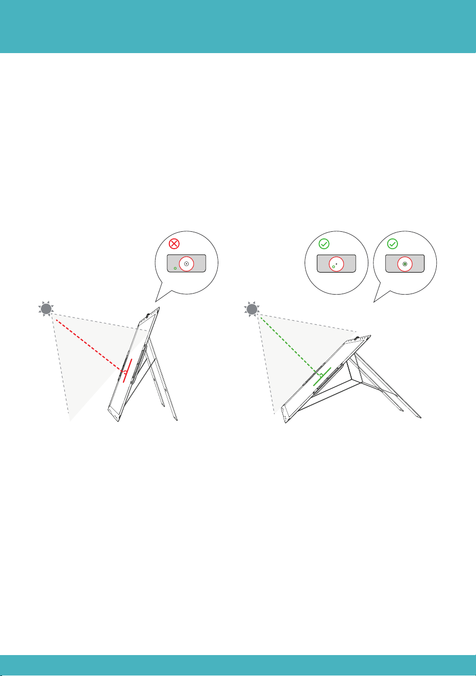
a)Undo all button straps, unfold the solar panels and spread the brackets.
b)Attach sundial indicator on the top of photovoltaic module.
c)Adjust the solar panel to focus sunlight within the sundial indicator's circle for
optimal illumination at its center.
d)Connect the solar panel to the portable power station and start charging.
05
90°
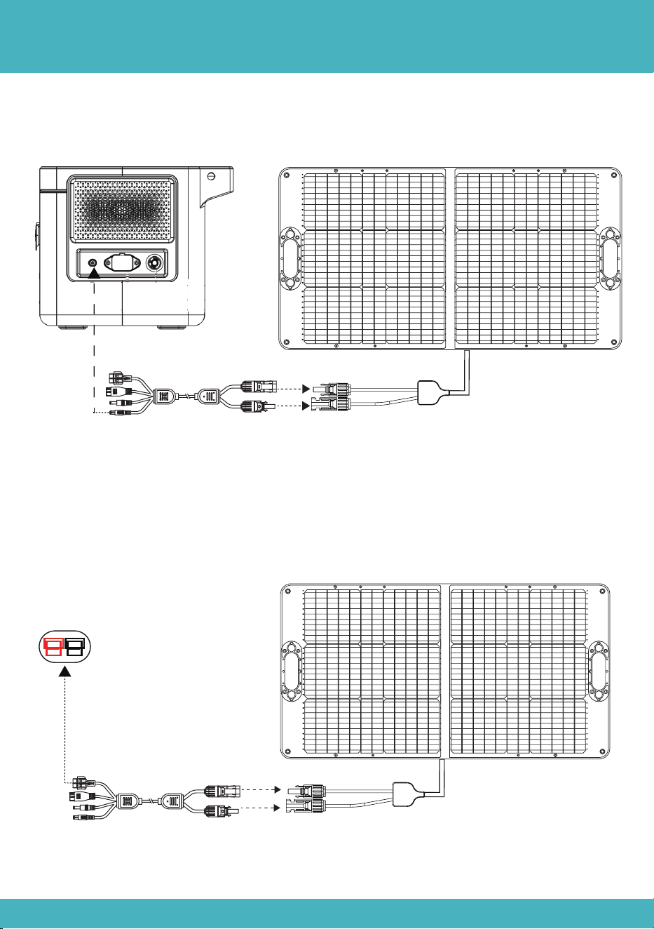
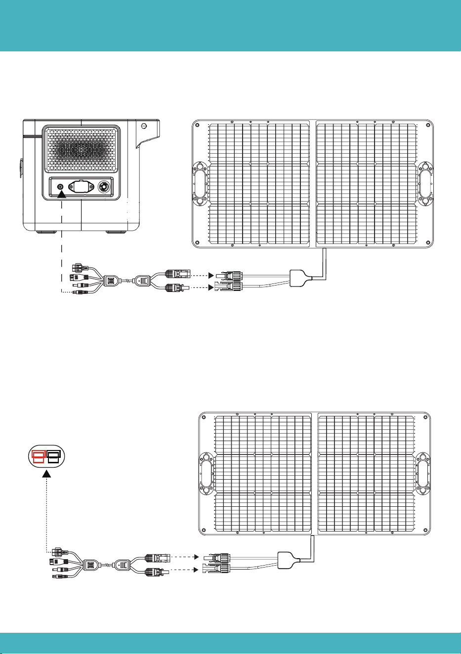
Connection Method
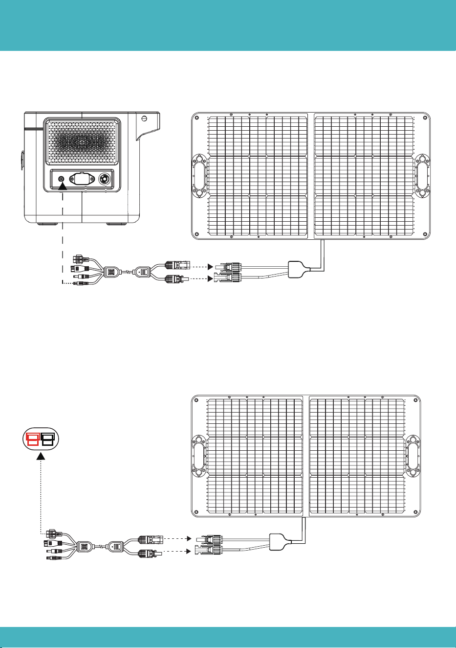
Method 2:Connect the MC4 male connector of the first panel to the MC4 female
connector of the next and so on. Then, connect the Anderson to MC4 charging cable
(a pair of MC4 connectors) to MC4 connectors of first and last one.
06
Method 1:Connect 7909 connector to the solar input port on the power station.
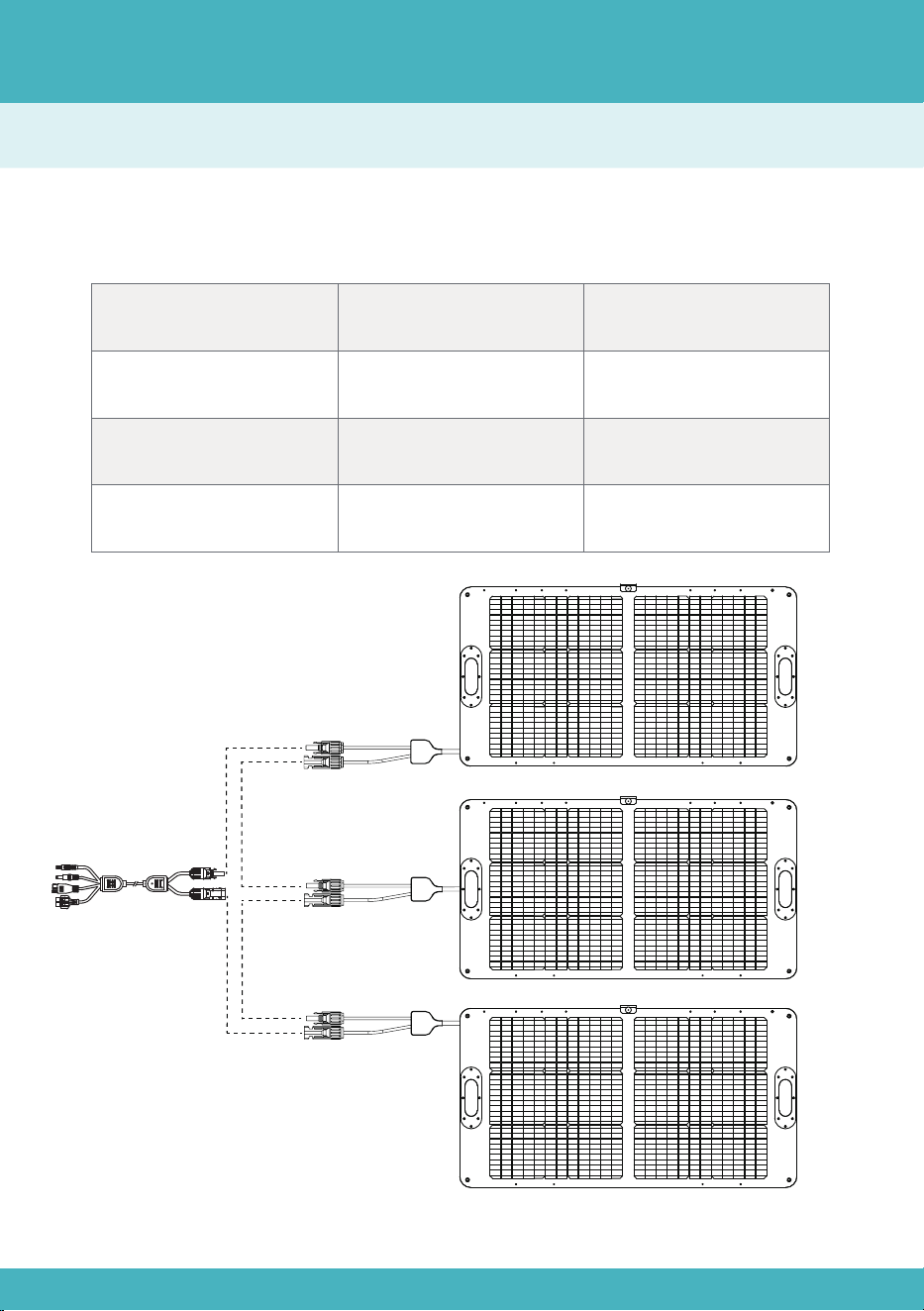
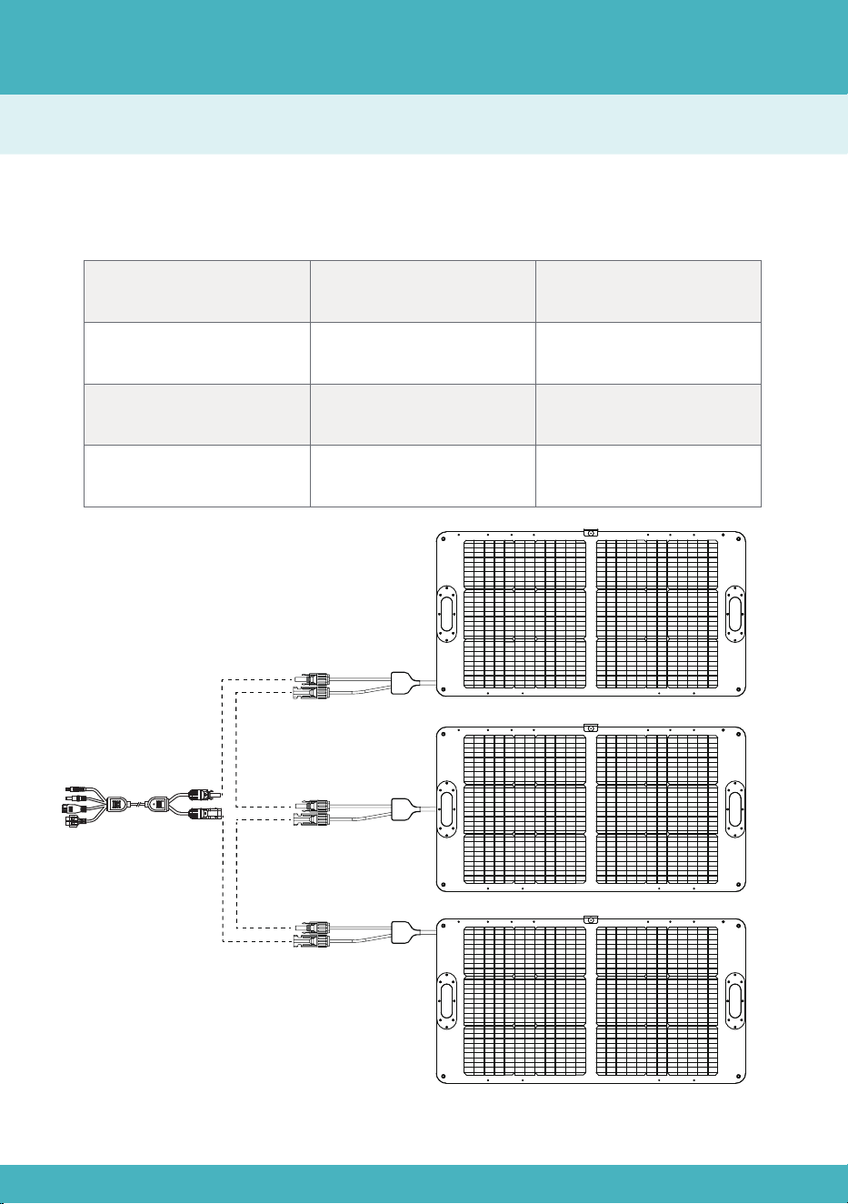
In Series
Please connect solar panels in same specifications, and it is recommended to
connect solar panels in same specifications.
In Series
Total Voltage
Adds up
Same as single solar panel
Total Voltage*Total Current
5.27A
24.4V*3*5.27A
24.4V*3
Total Current
Total Power
Example
Calculation Method
07
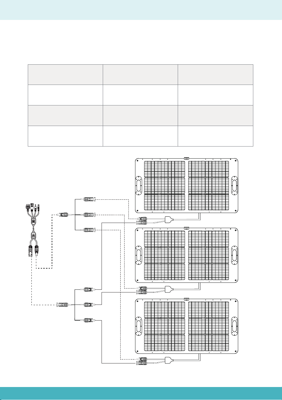
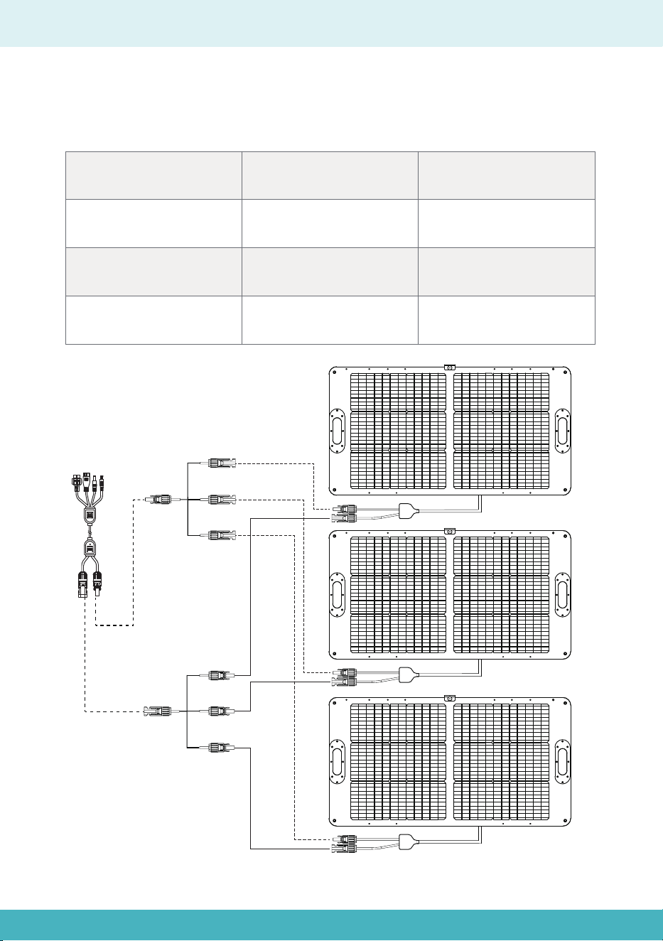
In Parallel
Please connect solar panels in same specifications, and it is recommended to
connect solar panels in same specifications.
In Parallel
Total Voltage
Same as single solar panel
Adds up
Total Voltage*Total Current
5.27A*3
24.4V*(5.27A*3)
24.4V
Total Current
Total Power
Example
08

Haftungsausschluss
Produktliste
Produktbeschreibung
Technische Daten
Produktbeschreibung
Gebrauchsanweisungen
Verbindungsmethode
Berechnungsmethode
In Reihe
Parallel
10
12-13
11
12
13
14
15
16
17
16-17
Deutsches Inhaltsverzeichnis
09

10
Haftungsausschluss
Bevor Sie dieses Produkt verwenden, lesen Sie bitte dieses Benutzerhandbuch sorg-
fältig durch, um sicherzustellen, dass Sie das Produkt vollständig verstehen und es
korrekt verwenden können. Bitte bewahren Sie dieses Benutzerhandbuch nach dem
Lesen an einem sicheren Ort auf, um es später bei Bedarf nachschlagen zu können.
Unsachgemäße Verwendung dieses Produkts kann zu schweren Verletzungen bei
Ihnen oder anderen sowie zu Produktschäden und Sachverlust führen. Durch die
Nutzung dieses Produkts gilt, dass Sie alle Bedingungen und Inhalte dieses Doku-
ments verstanden, anerkannt und akzeptiert haben. Das Unternehmen haftet nicht
für Schäden, die durch eine nicht bestimmungsgemäße Verwendung entgegen
den Anweisungen in diesem Benutzerhandbuch entstehen.
In Übereinstimmung mit geltenden Gesetzen und Vorschriften behält sich das
Unternehmen das Recht der endgültigen Auslegung dieses Dokuments und aller
damit verbundenen Unterlagen vor. Dieses Dokument kann ohne vorherige Ankün-
digung geändert, aktualisiert, überarbeitet oder aufgehoben werden.
Bitte besuchen Sie unsere Website, um die neuesten Produktinformationen zu
erhalten.
●Das Unternehmen haftet nicht für Schäden, die durch höhere Gewalt (z. B. Feuer,
Taifun, Überschwemmung, Erdbeben) oder durch Nutzung unter anderen
außergewöhnlichen Umständen durch den Kunden verursacht werden.
●Das Unternehmen übernimmt keine Haftung für Schäden, die durch die Verwend-
ung von nicht genormten Steckverbindern entstehen.
●Das Unternehmen haftet nicht für Schäden, die durch Nichteinhaltung des Stan-
dardbetriebs entstehen.
●Bitte zerlegen Sie das Produkt nicht. Andernfalls erlischt die Garantie.
10
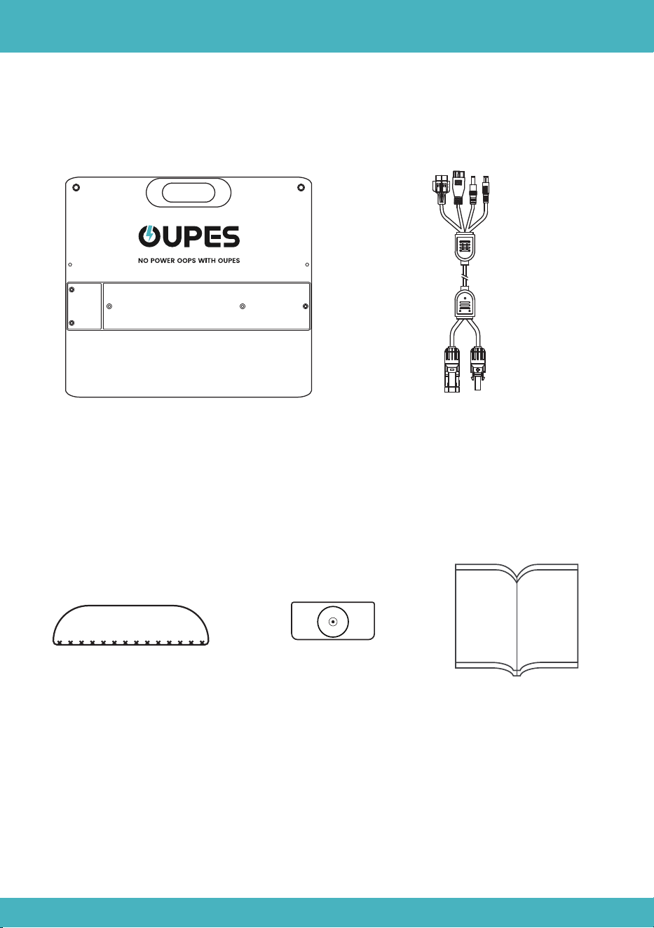
Solarmodul ×1
Sonnenuhr-Anzeiger ×1
Produktliste
Benutzerhandbuch ×1
11
MC4-Steckverbinder auf Ander-
son+XT60+7909+5521-Erweiterungskabel
Wasserfeste Basis*2
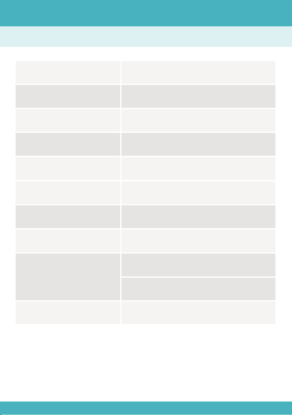
Produktbeschreibung
Nennleistung
Wirkungsgrad der Zelle
Leerlaufspannung
Kurzschlussstrom
100W
23%
24,4 V
5,27 A
Maximale Betriebsspannung 20,5 V
Maximaler Betriebsstrom
IP-Schutzart
Arbeitstemperatur
4,88 A
IP65
-4℉~185℉(-20℃~85℃)
Nettogewicht
9,92 lb (4,5 kg)
Abmessungen
Zusammengeklappt: 21,85 × 23,23 × 1,97 Zoll
(555 × 590 × 50 mm)
Ausgeklappt: 43,7 × 23,23 × 1,38 Zoll
(1110 × 590 × 35 mm)
12
Technische Daten
12
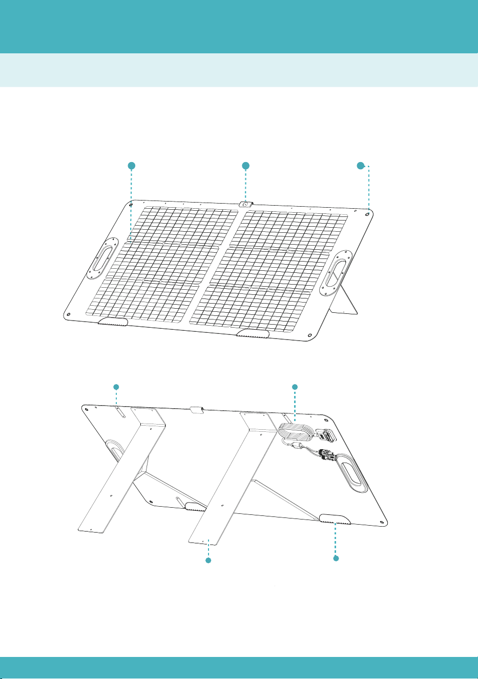
Produktbeschreibung
Übersicht
13
Knopfriemen
MontagelochPhotovoltaikmodul
Halterung
Sonnenuhr-Anzei-
ger (abnehmbar)
13
MC4-Steckverbinder-Kabel
Wasserfeste Basis
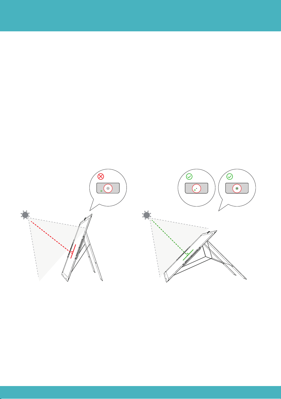
Gebrauchsanweisungen
a)Lösen Sie alle Knopfriemen, klappen Sie die Solarmodule auf und stellen Sie die
Halterungen auf.
b)Befestigen Sie den Sonnenuhr-Anzeiger an der Oberseite des Photovoltaikmoduls.
c)Richten Sie das Solarmodul so aus, dass das Sonnenlicht innerhalb des Kreises des
Sonnenuhr-Anzeigers gebündelt wird, um eine optimale Beleuchtung im Zentrum zu
erzielen.
d)Schließen Sie das Solarmodul an die tragbare Powerstation an und beginnen Sie
mit dem Laden.
14
90°
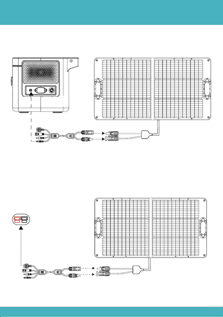
Verbindungsmethode
Methode 1: Verbinden Sie den 7909-Stecker mit dem Solareingangsanschluss an der
Powerstation.
Methode 2: Verbinden Sie den MC4-Stecker des ersten Moduls mit der MC4-Buchse
des nächsten Moduls und so weiter. Schließen Sie dann das Ander-
son-zu-MC4-Ladekabel (ein Paar MC4-Stecker) an die MC4-Stecker des ersten und
letzten Moduls an.
15
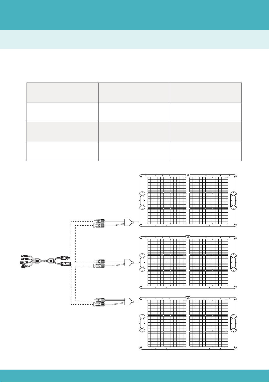
In Reihe
Bitte schließen Sie Solarmodule mit denselben Spezifikationen an; es wird empfohlen,
nur Solarmodule mit identischen Spezifikationen zu verbinden.
In Reihe
Gesamtspannung
Addiert sich
Gleich wie bei einem
einzelnen Solarmodul
Gesamtspannung
× Gesamtstrom
5,27 A
24,4 V × 3 × 5,27 A
24,4 V × 3
Gesamtstrom
Gesamtleistung
Beispiel
Berechnungsmethode
16
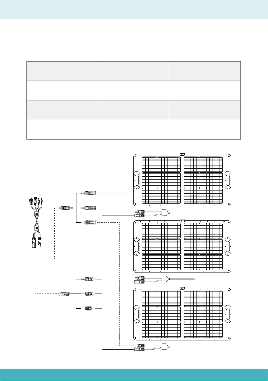
Parallel
Bitte schließen Sie Solarmodule mit denselben Spezifikationen an; es wird empfohlen,
nur Solarmodule mit identischen Spezifikationen zu verbinden.
Parallel
Gesamtspannung
Gleich wie bei einem
einzelnen Solarmodul
Addiert sich
Gesamtspannung
× Gesamtstrom
5,27 A × 3
24,4 V × (5,27 A × 3)
24,4 V
Gesamtstrom
Gesamtleistung
Beispiel
17

Clause de non-responsabilité
Liste des produits
Description du produit
Spécifications
Description du produit
Instructions d'utilisation
Méthode de connexion
Méthode de calcul
En série
En parallèle
19
21-22
20
21
22
23
24
25
26
25-26
Table des matières en français
18

Clause de non-responsabilité
Avant d'utiliser ce produit, veuillez lire attentivement ce manuel d'utilisation pour
vous assurer de bien comprendre le produit et de pouvoir l'utiliser correctement.
Après avoir lu ce manuel d'utilisation, veuillez le conserver dans un endroit sûr pour
consultation ultérieure. Une utilisation incorrecte de ce produit peut entraîner des
blessures graves pour vous-même ou autrui, ainsi que des dommages au produit
et des pertes matérielles. En utilisant ce produit, vous êtes réputé(e) avoir compris,
reconnu et accepté l'ensemble des termes et du contenu de ce document. La
société ne saurait être tenue responsable des dommages causés par le non-re-
spect de ce manuel d'utilisation lors de l'utilisation du produit.
Conformément aux lois et règlements, la société se réserve le droit d'interprétation
finale du présent document ainsi que de tous les documents relatifs à ce produit.
Ce document est susceptible d'être modifié, mis à jour, révisé ou résilié sans préa-
vis.
Veuillez consulter notre site web pour obtenir les dernières informations sur ce
produit.
●La société ne peut être tenue responsable de tout dommage causé par un cas de
force majeure (par exemple, incendie, typhon, inondation, tremblement de terre)
ou par une utilisation du client dans d'autres circonstances anormales.
●La société n'assume aucune responsabilité pour les pertes causées par l'utilisa-
tion de connecteurs non standard.
●La société ne sera pas responsable des dommages causés par le non-respect
du fonctionnement standard.
●Veuillez ne pas démonter le produit. Dans le cas contraire, la garantie sera
annulée.
19
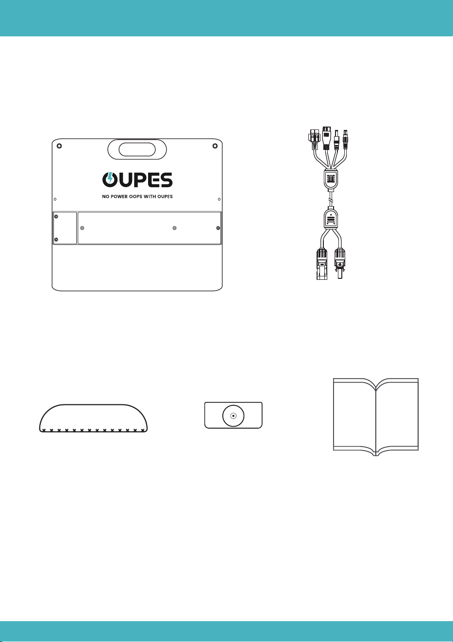
Indicateur de cadran solaire*1
Liste des produits
Manuel d'utilisation*1
Panneau solaire*1
20
Câble d'extension MC4 vers
Anderson+XT60+7909+5521
Base étanche*2
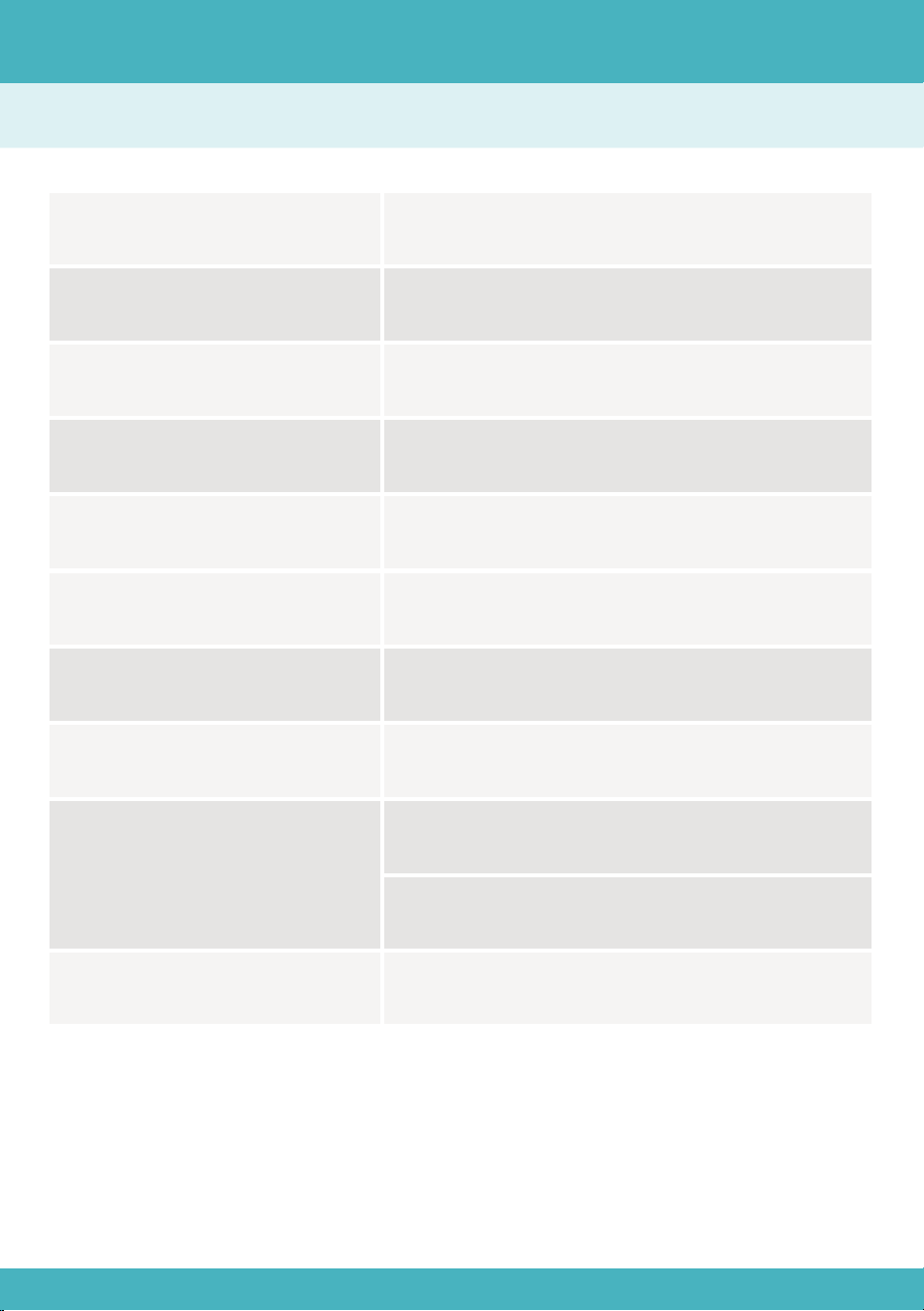
Description du produit
Puissance nominale
Efficacité cellulaire
Tension en circuit ouvert
Courant de court-circuit
100 W
23%
24,4 V
5,27 A
Tension de fonctionne-
ment maximale
20,5 V
Courant de fonctionne-
ment maximal
Indice IP
Température de
fonctionnement
4,88 A
IP65
-4℉~185℉(-20℃~85℃)
Poids net
9,92 lb (4,5 kg)
Dimension
Plié : 21,85*23,23*1,97 pouces
(555*590*50 mm)
Déplié : 43,7*23,23*1,38 pouces
(1110*590*35 mm)
Spécifications
21
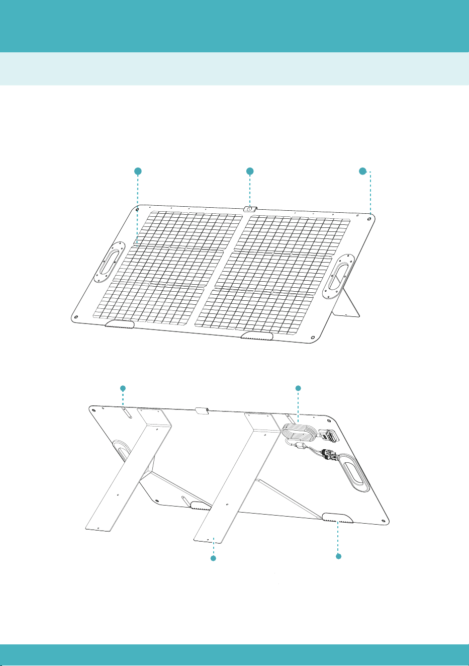
Description du produit
Aperçu
Bouton de fixation
Trou de montageModule photovoltaïque
Support
Indicateur de cadran
solaire (détachable)
22
Câbles à connecteurs MC4
Base étanche
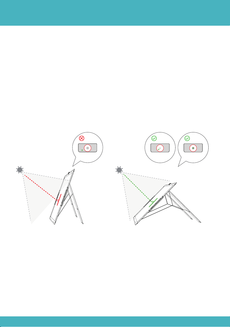
Instructions d'utilisation
a)Détachez toutes les sangles à boutons, dépliez les panneaux solaires et déployez
les supports.
b)Fixez l'indicateur de cadran solaire sur le dessus du module photovoltaïque.
c)Ajustez le panneau solaire de sorte que la lumière solaire se concentre dans le
cercle de cet indicateur, afin d'obtenir un éclairage optimal en son centre.
d)Connectez le panneau solaire à la station d'alimentation portable et commencez
la recharge.
23
90°
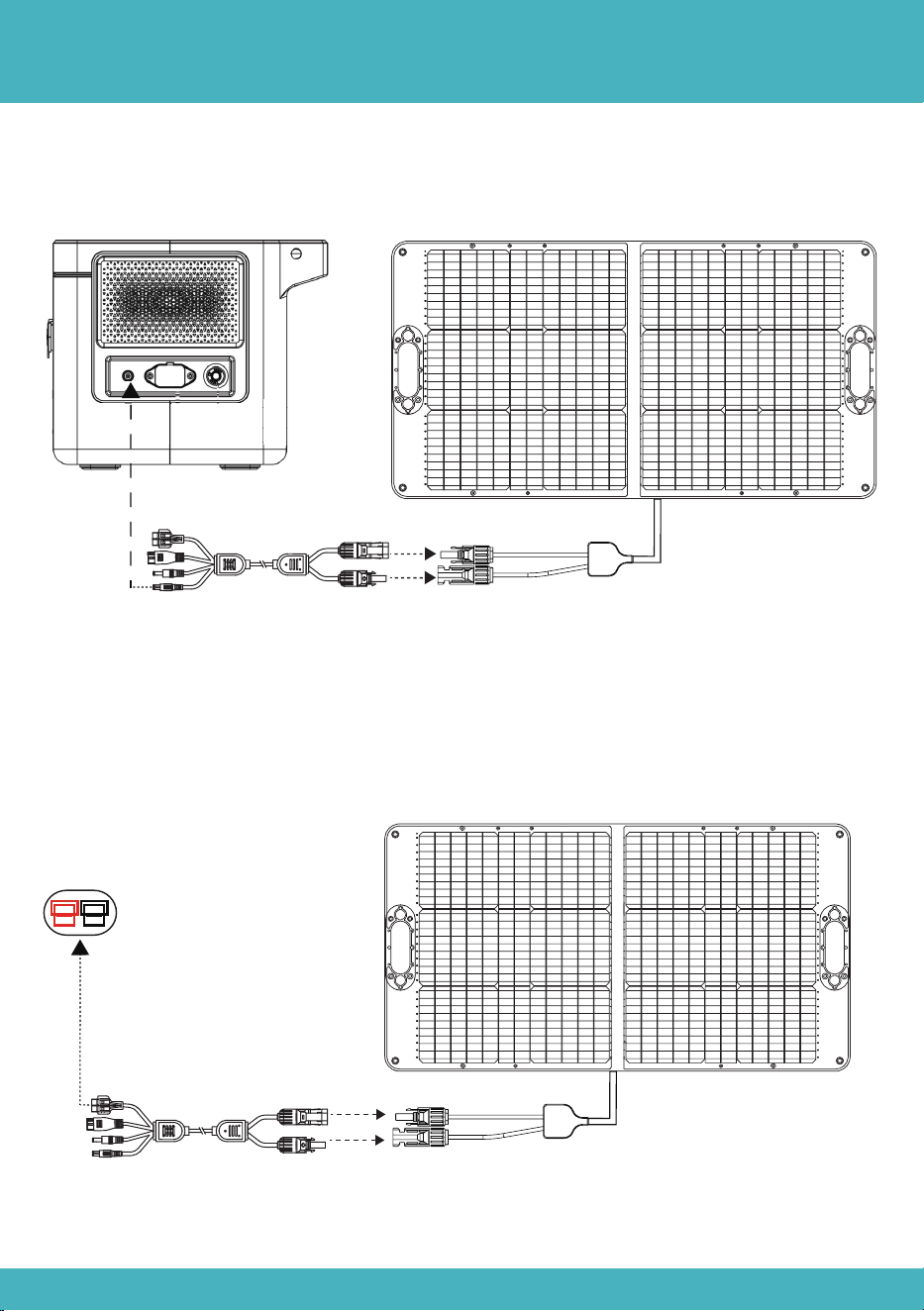
Méthode de connexion
Méthode 1 : Connectez le connecteur 7909 au port d'entrée solaire de la station
d'alimentation.
Méthode 2 : Connectez le connecteur mâle MC4 du premier panneau au connecteur
femelle MC4 du panneau suivant, et ainsi de suite. Ensuite, connectez le câble de
recharge Anderson à MC4 (une paire de connecteurs MC4) aux connecteurs MC4 du
premier et du dernier.
24
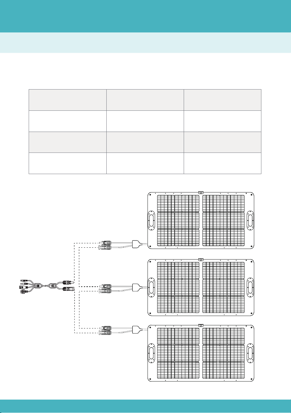
En série
Veuillez connecter des panneaux solaires de mêmes spécifications, et il est recom-
mandé de procéder ainsi.
En série
Tension totale
Somme
Identique à un panneau
solaire unique
Tension totale
* Courant total
5,27 A
24,4 V*3*5,27 A
24,4V*3
Courant total
Puissance totale
Exemple
Méthode de calcul
25
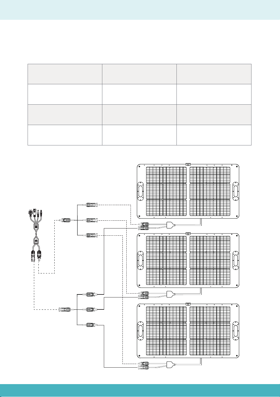
En parallèle
Veuillez connecter des panneaux solaires de mêmes spécifications, et il est recom-
mandé de procéder ainsi.
En parallèle
Tension totale
Identique à un panneau
solaire unique
Somme
Tension totale * Courant
total
5,27 A × 3
24,4 V × (5,27 A × 3)
24,4 V
Courant total
Puissance totale
Exemple
26

28
30-31
29
30
31
32
33
34
35
34-35
Indice in italiano
Esclusione di responsabilità
Elenco dei prodotti
Descrizione del prodotto
Specifiche
Descrizione del prodotto
Istruzioni per l'uso
Metodo di collegamento
Metodo di calcolo
In serie
In parallelo
27

Esclusione di responsabilità
Prima di utilizzare questo prodotto, si prega di leggere attentamente il presente
manuale utente per assicurarsi di comprendere appieno il prodotto e di poterlo
utilizzare correttamente. Dopo aver letto il presente manuale utente, si prega di
conservarlo in un luogo sicuro per futuro riferimento. L'uso improprio di questo
prodotto può causare gravi lesioni a se stessi o ad altri, oppure danni al prodotto e
perdite di proprietà. Utilizzando questo prodotto, si ritiene che l'utente abbia com-
preso, riconosciuto e accettato tutti i termini e i contenuti del presente documento.
L'azienda non sarà responsabile per eventuali danni causati dal mancato utilizzo
del prodotto da parte dell'utente in conformità con il presente manuale utente.
In conformità alle leggi e ai regolamenti, l'azienda si riserva il diritto di interpretazi-
one finale del presente documento e di tutti i documenti relativi a questo prodotto.
Il presente documento è soggetto a modifiche, aggiornamenti, revisioni o cessazi-
one senza preavviso.
Visitate il nostro sito web per le ultime informazioni sui prodotti.
●L'azienda non sarà responsabile di eventuali danni causati da cause di forza
maggiore (ad es. incendio, tifone, inondazione, terremoto) o dall'utilizzo in altre
circostanze anomali da parte del cliente.
●L'azienda non si assume alcuna responsabilità per eventuali perdite causate
dall'uso di connettori non standard.
●L'azienda non sarà responsabile di eventuali danni causati dal mancato rispetto
delle norme di funzionamento.
●Si prega di non smontare il prodotto. In caso contrario, la garanzia verrà invali-
data.
28
Indicatore della meridiana*1
Elenco dei prodotti
Manuale utente*1
Pannello solare*1
29
Cavo di prolunga MC4 per
Anderson+XT60+7909+5521
Base impermeabile*2
Descrizione del prodotto
Potenza nominale
Efficienza delle celle
Tensione a circuito aperto
Corrente di corto circuito
100 W
23%
24,4 V
5,27 A
Tensione di funziona-
mento massima
20,5 V
Corrente di funziona-
mento massima
Grado IP
Temperatura di funzion-
amento
4,88 A
IP65
-4℉~185℉(-20℃~85℃)
Peso netto
9,92 libbre (4,5 kg)
Dimensione
Piegato: 21,85*23,23*1,97pollici
(555*590*50mm)
Spiegato: 43,7*23,23*1,38pollici
(1110*590*35mm)
Specifiche
30
Descrizione del prodotto
Panoramica
Cinturino con bottone
Foro di montaggioModulo fotovoltaico
Staffa
Indicatore della meridiana
(staccabile)
31
Cavi con connettori MC4
Base impermeabile
Istruzioni per l'uso
a)Allentare tutte i cinturini con bottone, spiegare i pannelli solari e distendere le
staffe.
b)Fissare l'indicatore della meridiana sulla parte superiore del modulo fotovoltaico.
c)Regolare il pannello solare per concentrare la luce del sole all'interno del cerchio
dell'indicatore della meridiana, per un'illuminazione ottimale al centro.
d)Collegare il pannello solare alla stazione di alimentazione portatile e iniziare a
caricare.
32
90°
Metodo di collegamento
Metodo 1: Collegare il connettore 7909 alla porta di ingresso solare della stazione di
alimentazione.
Metodo 2: Collegare il connettore maschio MC4 del primo pannello al connettore
femmina MC4 del pannello successivo e così via. Quindi, collegare il cavo di carica da
Anderson a MC4 (una coppia di connettori MC4) ai connettori MC4 del primo e
dell'ultimo.
33
In serie
Si prega di collegare i pannelli solari nelle stesse specifiche e si consiglia di collegare i
pannelli solari nelle stesse specifiche.
In serie
Tensione totale
Si ammonta
Uguale a un singolo
pannello solare
Tensione totale*cor-
rente totale
5,27A
24,4V*3*5,27A
24,4V*3
Corrente totale
Potenza totale
Esempio
Metodo di calcolo
34
In parallelo
Si prega di collegare i pannelli solari nelle stesse specifiche e si consiglia di collegare i
pannelli solari nelle stesse specifiche.
In parallelo
Tensione totale
Uguale a un singolo
pannello solare
Si ammonta
Tensione totale*corrente
totale
5,27A*3
24,4V*(5,27A*3)
24,4 V
Corrente totale
Potenza totale
Esempio
35

Descargo de responsabilidades
Lista de Productos
Descripción del Producto
Especificaciones
Descripción del Producto
Instrucción para Uso
Método de Conexión
Método de Cálculo
En Serie
En Paralelo
37
39-40
38
39
40
41
42
43
44
43-44
Tabla de Contenido en Español
36

Descargo de responsabilidades
Antes de usar este producto, consulte cuidadosamente este manual del usuario
para asegurarse de que comprende completamente el producto y puede usarlo
correctamente. Después de leer este manual del usuario, consulte mantener
protocolo en un lugar seguro para futuras referencias. El uso inadecuado de
producto puede provocar lesiones graves a usted mismo o otros, o provocar
daños al equipo y pérdida de propiedad. Al usar producto, se considera que ha
entendido, reconocido y aceptado todos los términos matemáticos y contenidos
de documento. La Compañía no será responsable de ningún daño causado por el
incumplimiento por parte del usuario de utilizar este producto de acuerdo con
este manual del usuario.
De conformidad con las leyes y reglamentos, la compañía se reserva el derecho
de interpretación final de este documento y de todos los documentos relaciona-
dos con este producto. Este documento está sujeto a cambios, actualizaciones,
revisiones o terminación sin previo aviso.
Por favor visite nuestro sitio web para obtener la información más reciente del
producto.
Visitate il nostro sito web per le ultime informazioni sui prodotti.
●La empresa no será responsable de ningún daño causado por fuerza mayor (por
ejemplo, incendio, tifón, inundación, terremoto) o por el uso en otras circunstan-
cias anómalas por parte del cliente.
●La empresa no asume responsabilidad por pérdidas causadas por el uso de
conectores no estándar.
●La empresa no será responsable de ningún daño causado por el incumplimien-
to de la operación estándar.
●Por favor, no desmonte el producto. De lo contrario, la garantía quedará anula-
da.
37
Indicador de Reloj Solar*1Base impermeable*2
Lista de Productos
Manual del Usuario*1
Panel Solar*1
38
Cable de extensión MC4 a
Anderson+XT60+7909+5521
Descripción del Producto
Potencia Nominal
Eficiencia de la Célula
Voltaje de Circuito Abierto
Corriente de Cortocircuito
100 W
23%
24,4 V
5,27 A
Voltaje Máximo de
Funcionamiento
20,5 V
Corriente Máxima de
Funcionamiento
Grado IP
Temperatura de Funcio-
namiento
4,88 A
IP65
-4℉~185℉(-20℃~85℃)
Peso Neto
9,92 lb (4,5 kg)
Dimensiones
Plegado: 21,85*23,23*1,97 pulgadas
(555*590*50 mm)
Desplegado: 43,7*23,23*1,38 pulgadas
(1110*590*35 mm)
Especificaciones
39
Descripción del Producto
Resumen
Correa de Botón
Agujero de MontajeMódulo Fotovoltaico
Soporte
Indicador de Reloj Solar
(Desmontable)
40
Cables de conectores MC4
Base impermeable
Instrucción para Uso
a)Deshaga todas las correas de botón, despliegue los paneles solares y extienda los
soportes.
b)Coloque el indicador de reloj solar en la parte superior del módulo fotovoltaico.
c)Ajuste el panel solar para enfocar la luz solar dentro del círculo del indicador de
reloj solar, logrando una iluminación óptima en su centro.
d)Conecte el panel solar a la estación de energía portátil y comience a cargar.
41
90°
Método de Conexión
Método 1: Conecte el conector 7909 al puerto de entrada solar de la estación de
energía.
Método 2: Conecte el conector MC4 macho del primer panel al conector MC4 hembra
del siguiente y así sucesivamente. Luego, conecte el cable de carga Anderson a MC4
(un par de conectores MC4) a los conectores MC4 del primero y del último.
42
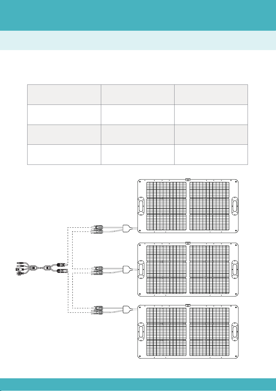
En Serie
Conecte paneles solares con las mismas especificaciones, y se recomienda conectar
paneles solares con las mismas especificaciones.
En Serie
Voltaje Total
Se suma
Igual que un solo
panel solar
Voltaje Total*Corriente
Total
5,27 A
24,4 V*3*5,27 A
24,4 V*3
Corriente Total
Potencia Total
Ejemplo
Método de Cálculo
43
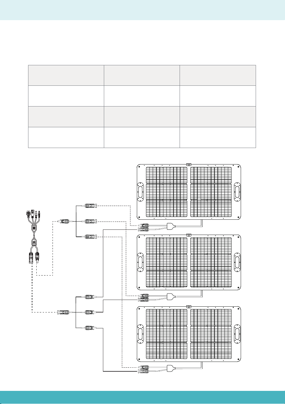
En Paralelo
Conecte paneles solares con las mismas especificaciones, y se recomienda conectar
paneles solares con las mismas especificaciones.
En Paralelo
Voltaje Total
Igual que un solo panel
solar
Se suma
Voltaje Total*Corriente
Total
5,27A*3
24,4 V*(5,27 A*3)
24,4 V
Corriente Total
Potencia Total
Ejemplo
44