
1
2
Revision
Description
A
First Edition
B
Second Edition
Revision History
USER MANUAL
Revision B – 5/29/2017
© 2013 Canada Metal (Pacific) Limited. All rights reserved.
The information contained in this document is the sole property of Canada Metal
(Pacific) Limited. Any reproduction in part or whole without the written permission
of Canada
Metal (Pacific) Limited is prohibited. Canada Metal (Pacific) Limited will not be
liable for errors contained herein or for incidental or consequential damages in
connection with the furnishing, performance or use of this document.
To the best of our knowledge, the information in this document was correct at the
time it was produced. However, Canada Metal (Pacific) Limited cannot accept
liability for any inaccuracies or omissions it may contain. In addition, our policy of
continuous product improvement may change specifications without notice. As a
result, Canada Metal (Pacific) Limited cannot accept liability for any differences
between the product and this document. Please visit www.intellisteer.com to en-
sure you have the most up-to-date version of the documentation for your product.
3
4
CONTENTS
1 Introduction. ................................................................................ 4
2 Installation. ................................................................................. 6
2.1 Included Parts ......................................................................... 6
2.2 Tools Required ........................................................................ 6
2.3 Battery Installation or Replacement .................................... 7
2.4 Mounting Receiver ................................................................. 8
2.5 Crimp Connections ................................................................ 8
2.6 Connecting To A Standalone Drive Unit .............................. 9
2.7 Connecting To An Autopilot System .................................. 10
2.8 Power Cable Gauge Recommendations .......................... 12
2.9 Verify Installation .................................................................. 13
3 Operation. ................................................................................. 14
3.1 Power On/Off ........................................................................ 14
3.2 Steering ................................................................................. 15
3.3 Auto Shut Off ........................................................................ 16
3.4 Overload Protection ............................................................. 16
4 Adding Or Replacing A Pendant. ........................................... 17
4.1 Pairing Pendant To Receiver .............................................. 17
5 Appendix. .................................................................................. 18
5.1 Warnings ............................................................................... 18
5.2 Troubleshooting .................................................................... 19
5.3 Specification .......................................................................... 20
5.4 FCC/CE Statements ............................................................ 21
5.5 Limited Warranty .................................................................. 21
1.
Introduction
Congratulations on your purchase of an Intellisteer Wire-
less Controller. This simple yet powerful system is designed
to free you from the need to hand steer your boat from the
helm, providing wireless jog steering control from anywhere
on your boat.
There is an Intellisteer model suitable for almost any boat.
Whether you have cable or hydraulic steering, with an au-
topilot or without, Intellisteer has a configuration that can
provide you with the freedom of wireless steering.
This manual covers the
installation and operation of
the standalone version of the
Intellisteer, designed to
interface with an existing au-
topilot and drive installation
whether or not the existing
course computer is opera-
tional. As long as the drive
unit is functional, Intellisteer
can control it.
5
6
If you do not have an existing autopilot installation, there are
other Intellisteer system packages which bundle the wireless
controller with a specially designed steering drive unit.
These include:
• Intellisteer Type R provides remote steering for auxiliary
or primary outboards or even sterndrives
• Intellisteer Type S provides a helm replacement for
remote steering of cable steered boats
• Intellisteer Type T provides a helm replacement for
remote steering of cable steered boats with tilt steering
• Intellisteer Type H provides remote steering for
hydraulically steered boats.
Instructions covering the installation of these Intellisteer
steering drives are included with the drive units in the system
kits.
More information can be found at www.intellisteer.com
2.
Installation
The Intellisteer Wireless Controller is designed to be used
with any reversing steering drive unit requiring less than 25A
peak operating current, whether mechanical or hydraulic.
While Intellisteer can be integrated with an Autopilot Course
Computer, it does not require one to operate. It is not suita-
ble for use with “all in one” cockpit autopilots with an integrat-
ed course computer.
It is also not suitable for use on boats with a positive ground
system.
It should not be fitted to boats where the maximum horse-
power of the engines exceeds the maximum horsepower
rating for the vessel as stated on the vessel manufacturers
tag.
2.1 Included Parts
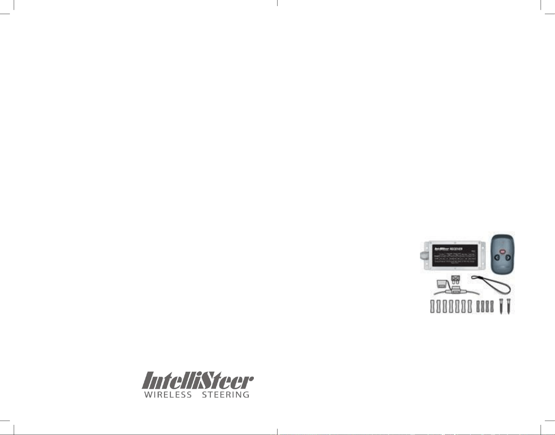
Before installation, check your kit includes all required parts:
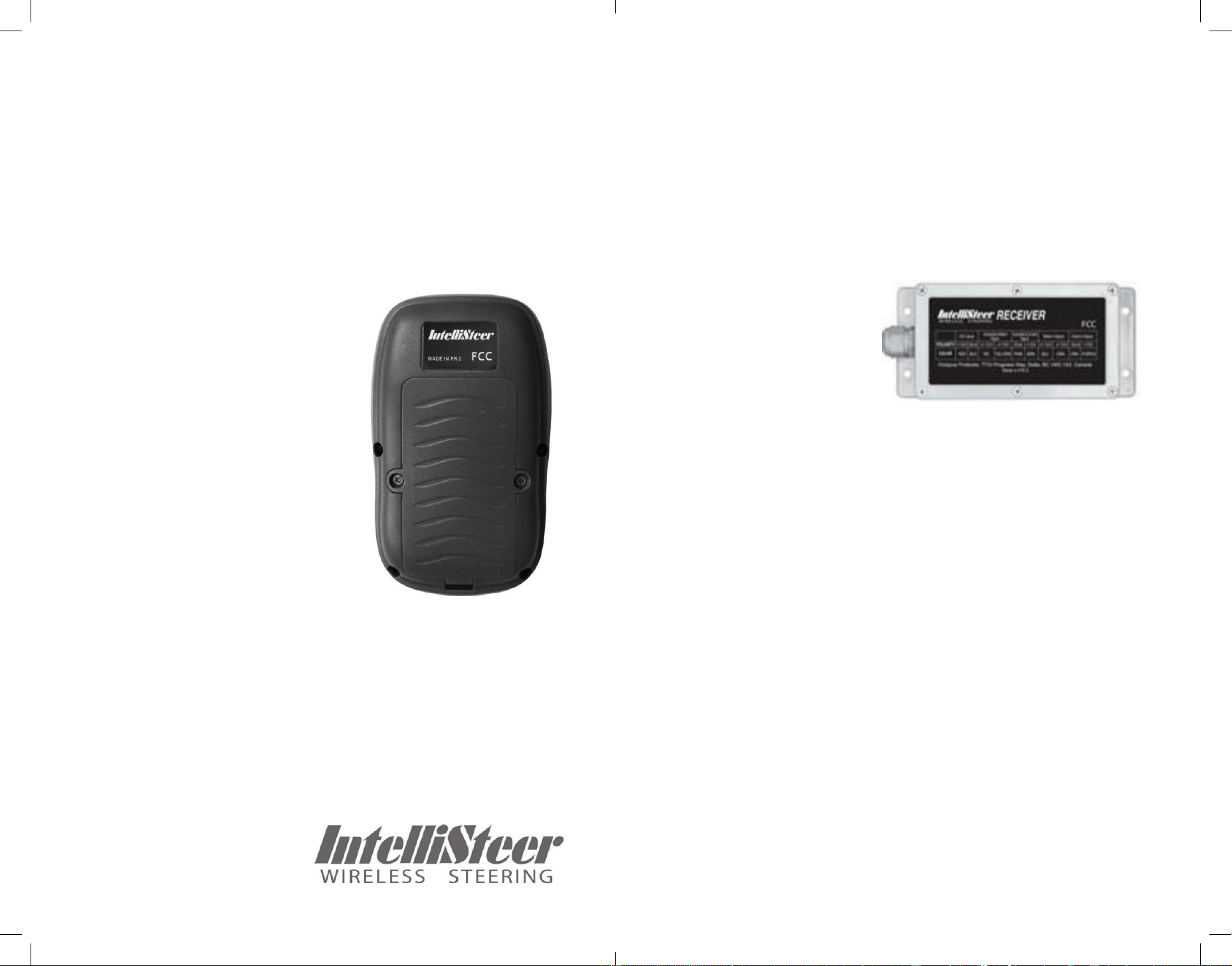
• Intellisteer Wireless Receiver
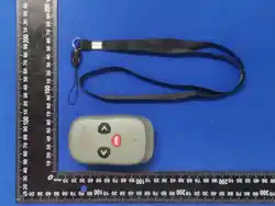
• Intellisteer Wireless Pendant
• Pendant Lanyard
• 7 Blue Crimp Connectors (14-
16 GA)
• 4 Red Crimp Connectors (18-22
GA)
• 25A Inline fuse & Fuse Holder
• 4 Mounting Screws
2.2 Tools Required
• Medium (#1) Phillips screwdriver for Receiver mounting
screws.
• Multi-meter for troubleshooting
• Hand crimp tool (double action recommended)
7
8
2.3 Battery Installation or Replacement
The pendant is powered by two AAA batteries (supplied pre-
installed in pendant). To replace these batteries:
• Remove two screws on back of pendant and remove cover.
• Install or replace the 2 batteries, noting the correct polarity.
• Place cover and secure with the
two screws - do not to over-tighten.
• Dispose of old batteries properly.
If the unit will not be used for a
long period of time, it is recom-
mended that the batteries be re-
moved to prevent damage due to
leakage from a discharged battery.
2.4 Mounting Receiver
The Receiver should be mounted where it has access to the
drive unit wiring and a 12v power supply (ideally close to the
autopilot course computer if fitting to a boat with an autopilot
system). Although the Receiver is
waterproof the location should not be exposed to the ele-
ments to protect the wiring connection from corrosion. If this
is not possible, all connections should be protected using
adhesive heatshrink sleeving.
Mount the Receiver us-
ing the four self-tapping
screws supplied.
Intellisteer Receiver
2.5 Crimp Connections
Positive crimp connections are critical to reliable operation;
ensure that the stripped wires are fully inserted into the
crimp and that the crimp is fully engaged. Using a double-ac-
tion hand crimping tool will give the best results, although a
standard single-action crimp can work well if used correctly.
Pull lightly on the wires after crimping to ensure a solid con-
nection. After crimping, heat the connector’s insulated barrel
with a small torch or heat gun to protect from corrosion.
2.6 Connecting to a Standalone Drive Unit
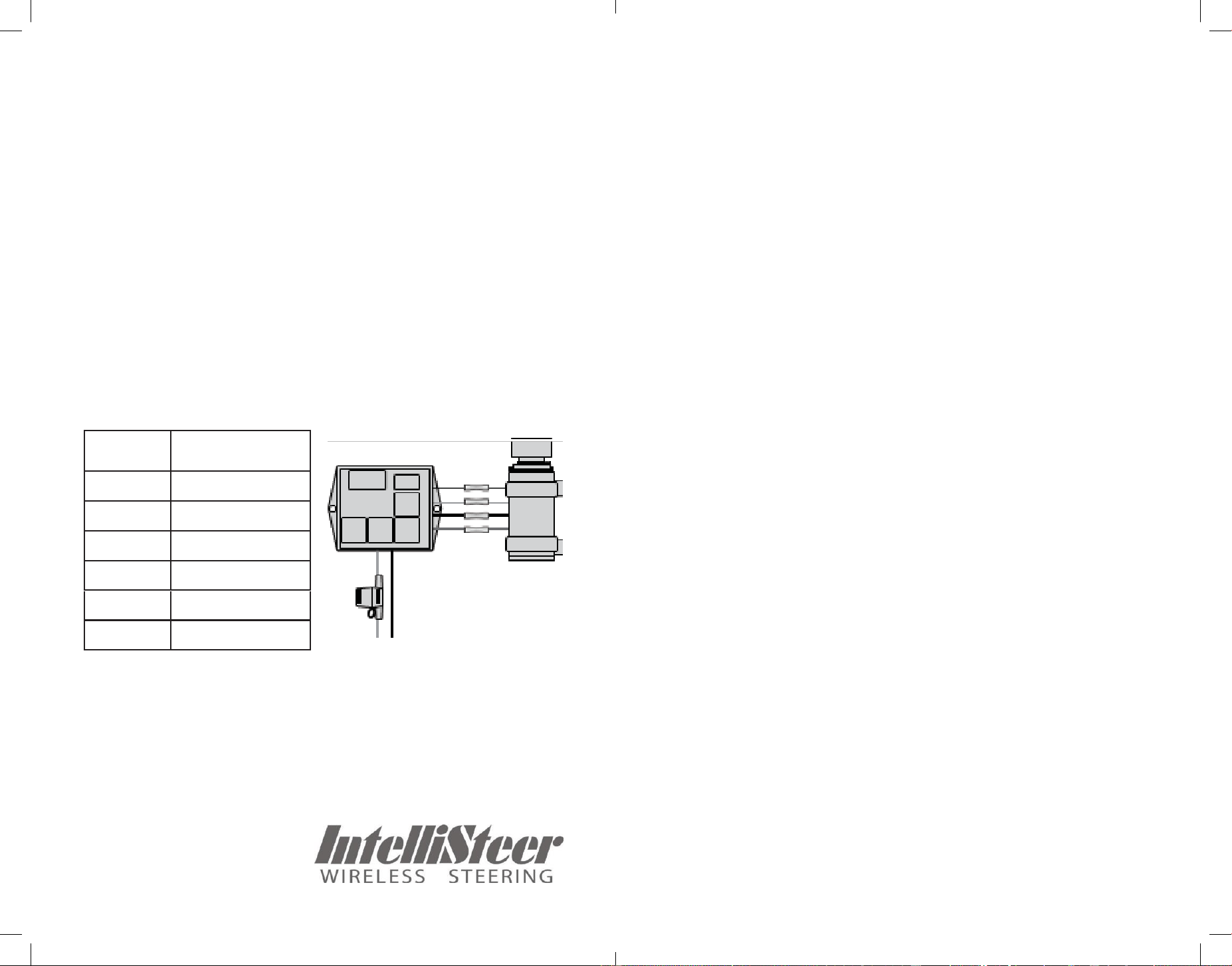
Typically there are 4 wires from a steering drive unit: two
heavy wires to drive the motor, and two lighter wires to ac-
tuate the clutch (for a mechanical drive) or bypass solenoid
(for a hydraulic drive) if required. Some drives do not have a
clutch – refer to your drive instructions for confirmation.
9
10
Cut back and strip the drive input and clutch wires from the
drive unit and connect to the Intellisteer Receiver as shown
in Table 1, using the supplied crimp connectors. If the steer-
ing direction does not match that indicated on the Pendant,
the drive input wires can be reversed. See Troubleshooting
section for more details.
Drive clutches do not usually have a polarity and the two
wires can be connected either way round. If the drive does
indicate a polarity, match to the clutch input on the Intellisteer
Receiver: + to Drive Unit Clutch 1, and – to Drive Unit
Clutch 2.
Fit the supplied inline fuse to the 12V+ wire, and connect the
ground line directly to the Intellisteer Receiver ground wire.
Intellisteer Receiver Steering Drive
12v DC + -
NOTE: For a standalone drive installation the four Course
Computer wires (Yellow, Yellow/Green, Brown and Pink) are
not used, and should be wrapped with electrical tape and
secured.
2.7 Connecting to an Autopilot System
Typically there are 4 wires between the autopilot course
computer and drive unit: two heavy wires to drive the motor,
and two lighter wires to actuate the clutch (for a mechanical
drive) or bypass solenoid (for a hydraulic drive) if required.
Some drives do not have a clutch – refer to your drive in-
structions for confirmation.
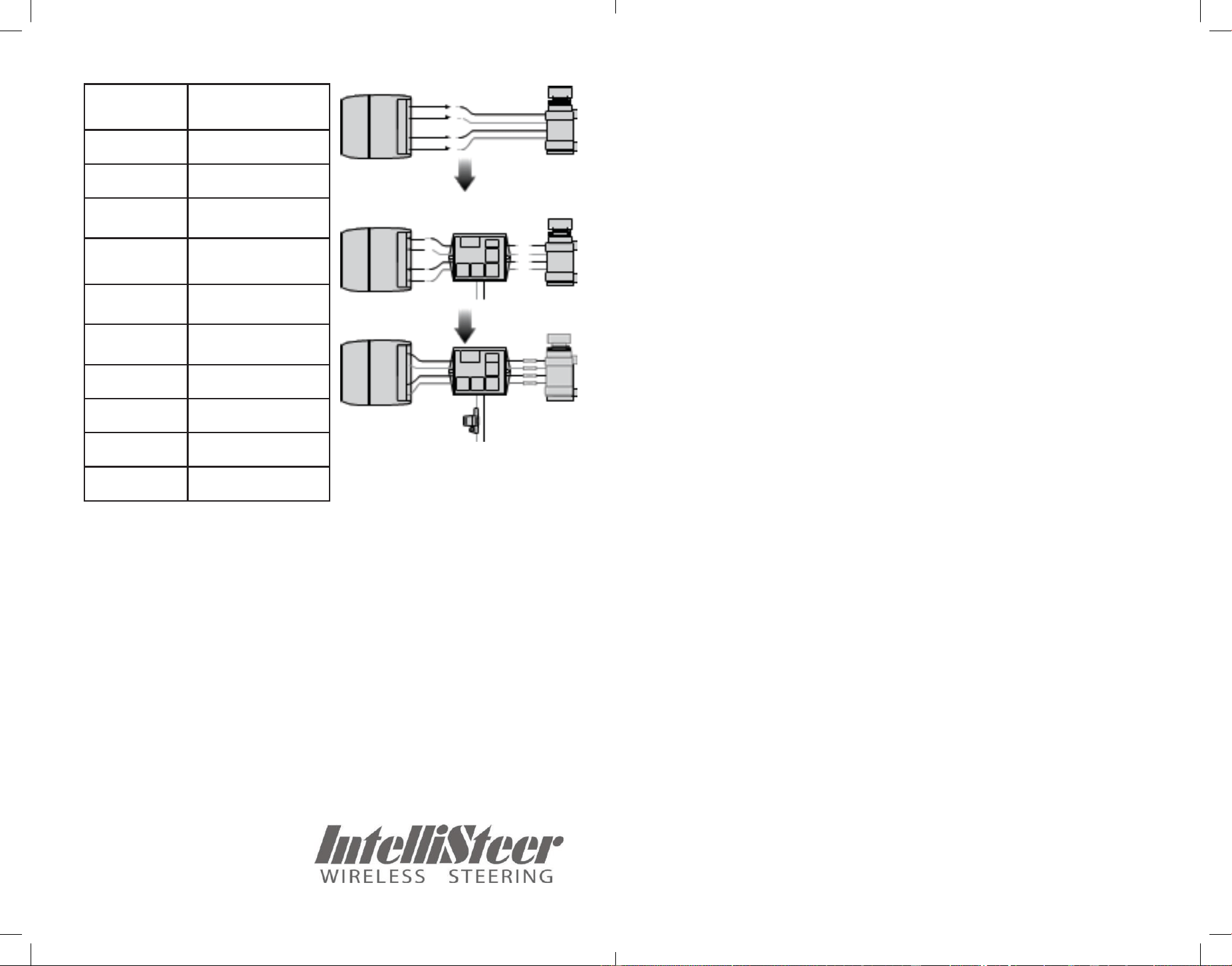
Disconnect the drive output and clutch wires from the course
computer and connect these to the corresponding drive unit
input and drive unit clutch wires on the Receiver as per Table
2, using the supplied crimp connectors. Connect the Course
Computer Drive Output and Course Computer Clutch wires
from the Receiver to the corresponding connectors on the
course computer - refer to your autopilot manual for the wire
colour coding between the autopilot course computer and
drive unit.
Autopilot drive clutches do not usually have a polarity and
the two wires can be connected either way round. If the au-
topilot clutch output does specify a polarity, connect Course
Computer Clutch Output + to Course Computer Clutch 1 on
Receiver, and Drive Unit Clutch 1 to + clutch input on Drive.
Fit the supplied inline fuse to the 12V+ wire, and connect the
ground line directly to the Intellisteer Receiver ground wire.
NOTE: Additional crimp connectors are supplied if it is not
possible to locate the Receiver close enough to the course
computer to be wired directly to it as described above and
it is necessary to splice the Receiver into the middle of the
wiring run.
Fuse
Intellisteer
Receiver
Connection
Red
Power 12v +
Black
Power Ground –
Blue
Drive Unit Input +
Green
Drive Unit Input –
Orange
Drive Unit Clutch 1
Purple
Drive Unit Clutch 2
11
12
Table 2
12v DC + -
2.8 Power Cable Gauge Recommendations
As power to the drive unit is supplied by the Intellisteer Re-
ceiver when operating, it is recommended that a minimum of
14GA wire be used for the power connection. Heavier gauge
wire may be required for longer runs and/or larger drive
units.
2.9 Verify Installation
• Check that the mounting and all connections are tight and
secure.
• Turn on the system with the Pendant ON/OFF button.
• Press the “<” or “>” buttons, and ensure that the boat
steers in the correct direction - if not, reverse the polarity of
the drive connections.
• If you are interfacing with an Autopilot course computer,
turn the Pendant off and ensure that the Autopilot operates
correctly as normal. Any problems likely relate to the polarity
of the clutch or drive connections - refer to the troubleshoot-
ing guide.
• Once you have verified the installation, you should famil-
iarize yourself with the operation of the Intellisteer Wireless
Controller while at the dock.
Course
Computer
Autopilot
Drive
Intellisteer
Receiver
Fuse
Intellisteer
Receiver
Connection
Red
Power 12v +
Black
Power 0v -
Yellow
Course Computer
Drive Output +
Yellow/
Green
Course Computer
Drive Output –
Brown
Course Computer
Clutch 1
Pink
Course Computer
Clutch 2
Blue
Drive Unit Input +
Green
Drive Unit Input –
Orange
Drive Unit Clutch 1
Purple
Drive Unit Clutch 2
13
14
3.
Operation
The Intellisteer Wireless System can be used for steering
control while trolling, or more generally as a second steering
station on the boat.
IMPORTANT: It is critical that the operator keeps a watch
for hazards at all times while underway - it is the operator’s
responsibility to ensure safe navigation of the vessel.
3.1 Power On/Off
If interfaced with an Autopilot, the Autopilot must be turned
off or put into standby mode before activating the Intellisteer
Wireless Controller to prevent interactions between the two
controllers. If both Intellisteer and the Autopilot are steering
at the same time, unpredictable results can occur.
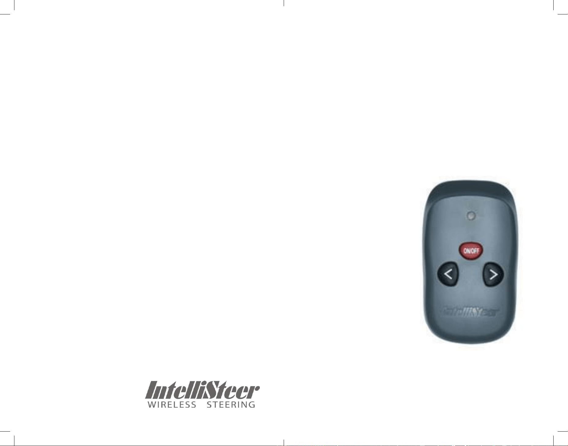
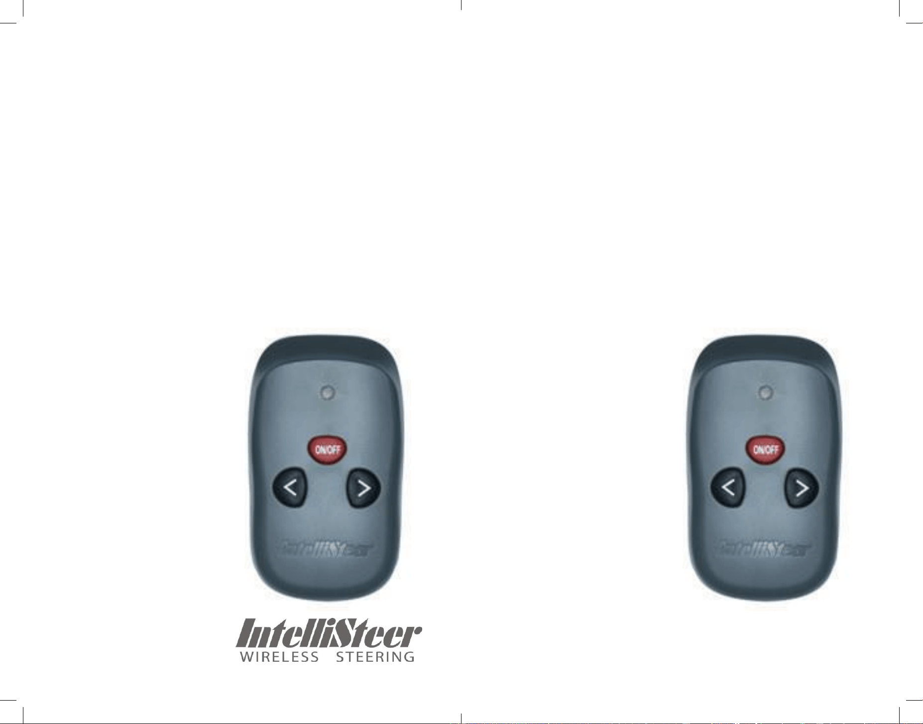
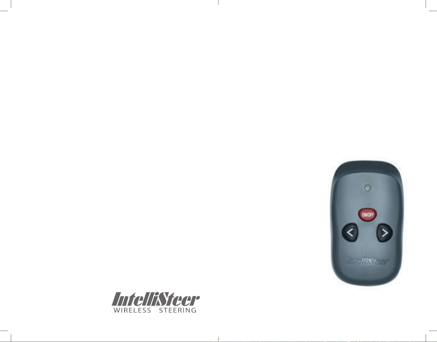
Press the red ON/OFF
button on the Pendant to
activate the Intellisteer Wire-
less System. The LED will
turn red for approximately 2
seconds during initialization,
then flash once every two
seconds to indicate that the
system is operational.
When the Intellisteer Wire-
less System is on, the pen-
dant jog steering buttons are
active.
When the “<” or “>” button is pushed, the clutch is engaged,
and the drive is activated. The LED indicator flashes contin-
uously while the steering buttons are pressed and the Pen-
dant is transmitting.
When the button is released, the clutch is disengaged and
manual steering is re-enabled.
Press ON/OFF to power off the Intellisteer and return to nor-
mal operation - the pendant LED will stop flashing and the
autopilot will be reconnected.
3.2 Steering
With the system powered on, press “<” or “>” on the pen-
dant to steer the boat to the Left or Right. As long as “<” or
“>” is pressed, power will be
supplied to the drive unit and
it will keep steering further in
the indicated direction until
the button is released. To
return the steering to straight
ahead, it will be necessary to
center the rudder by press-
ing the opposite button until
the boat is steering straight
ahead. With practice quite
precise steering control can
be achieved.
15
16
3.3 Auto Shut-off
If the Intellisteer is not used for 30 minutes the Pendant will
automatically power down to save battery life. To re-activate
the Pendant, simply press the ON/OFF button.
3.4 Overload Protection
To prevent electrical or mechanical damage in the event that
the drive unit is driven all the way to one end of the steering
system travel the Intellisteer Receiver incorporates overload
protection. If the drive unit “hits the stops” and can go no
further, but power continues to be applied, the Intellisteer Re-
ceiver will disconnect power to the drive unit. To reconnect
power to the drive unit, simply steer the boat in the other
direction.
Hydraulic pumps have higher current demands than me-
chanical drives, and can generate large current spikes when
the steering direction is quickly reversed. In this situation,
rapidly changing steering direction back and forth between
“<” or “>”, with no pause between the button pushes, can
cause large current spikes which may trigger the overload
protection circuit. If this occurs, simply wait for 1 second, and
then steer the boat in the other direction from the last button
push. This will reset the overload circuit.
To prevent this accidental activation of the overload protec-
tion circuit with hydraulic systems, simply wait for 1 second
between releasing one steering button and pushing the
other.
4.
Adding or Replacing a Pendant
Your Intellisteer Pendant and the Receiver are paired using
a unique code, ensuring that only your Pendant will control
your Receiver. The Pendant and Receiver are paired at the
factory and are ready to use out the box.
The Intellisteer Receiver can be paired with two Pendants at
the same time, in which case it can be controlled by either
one. If the user attempts to pair with a third Pendant it will
take the place of the first Pendant paired - only two Pendants
can be paired at a time.
4.1 Pairing Pendant to Receiver
1. Turn the Pendant on.
2. Disconnect power to the Receiver (remove inline fuse,
turn off breaker, etc).
3. Wait 10 seconds, then
reconnect power to the Re-
ceiver.
4. Within 5 seconds of restor-
ing power to the Receiver,
press both the “<” or “>” but-
tons on the Pendant at the
same time until you hear a
beep. You are now in Pairing
Mode.
5. Press any button and you
will hear two beeps. Then
wait 3-5 seconds until you
hear a long beep to exit from
Pairing Mode.
6. Turn the Pendant off and on. The units are now paired!

17
18
5.
Appendix
5.1 Warnings
Always maintain a permanent watch, this will allow you to
respond to situations as they develop. Failure to maintain a
permanent watch puts yourself, your vessel and others at
serious risk of harm.
This product must be installed and operated in accordance
with the instructions provided. Failure to do so could result in
personal injury, damage to your vessel and/or poor product
performance.
In the event of UNCONTROLLED remote steering or oth-
er EMERGENCY situations, return to MANUAL steering is
provided by turning the Intellisteer System OFF with the Pen-
dant ON/OFF button. If this is not practical, the helm can be
forced to one side or the other to manually override the auto-
pilot drive and power to the Receiver should be removed as
quickly as possible. It is STRONGLY advised that the helms-
man be formally familiarized with this OVERRIDE procedure.
Do NOT install in a location where it will be exposed to a
hazardous/flammable atmosphere (such as near fuel tanks).
Some autopilot drives connect directly to the helm wheel and
incorporate a manual clutch release. While this clutch is en-
gaged, it may be difficult or impossible to manually override
the autopilot drive. For this type of installation, users should
familiarize themselves with the use of the clutch release so
as to allow quick return to manual control in the event of an
emergency.
5.2 Troubleshooting
Pendant does not operate correctly (LED indicator not
operating normally)
• Check or replace Pendant batteries.
Receiver is not operating
• Check or replace 25A inline fuse.
• Check power supply polarity, and correct if it is reversed.
The Receiver is protected against reverse polarity, and no
damage will result. However the unit will not operate if the
power supply leads are reversed.
• Overload protection may have been activated. Try steering
in the other direction to reset the overload protection
Clutch does not operate correctly when Intellisteer is
steering
• Check Intellisteer clutch output polarity and correct if re-
versed (the clutch on most autopilot drive units is not polarity
sensitive, however some are)
Clutch operates correctly when Intellisteer is steering,
but not when the Autopilot is
• Check Intellisteer clutch input polarity and correct if re-
versed.
Steering is reversed on Intellisteer Operation
• Reverse drive polarity between the Intellisteer Receiver
and the drive unit.
Steering is reversed on Autopilot Operation
• Reverse drive polarity between the course computer and
the Intellisteer Receiver.
No communication between Pendant and Receiver
• Re-pair Pendant and Receiver
• There may be signal interference if the boat has steel bulk-
heads/decks or there are other metallic objects between the
Pendant and Receiver. Consider relocating the Receiver to a
place where there is no metal blocking the signal.

19
20
5.3. Specification
Wireless Controller & Receiver
Frequency: 315MHz
Meets FCC EMC standards Operating temperature range -
30C to +80C Handheld and Receiver can be paired in field
Pendant and Receiver auto-off in 30 minutes if no usage
Over 1 Million control codes provide enhanced security
Handheld Pendant
Water resistant
Supplied with 2x AAA batteries
Wireless Receiver & Motor Controller
Waterproof
Motor drive capability up to 25A Overload protection
Reverse polarity protection
12VDC nominal (9-16V DC operating range)
Offers pass-through capability for Autopilot motor and clutch
control circuits
Can be controlled by up to two Pendants
5.4. FCC/CE Statements
The Intellisteer Wireless Controller complies with the FCC
Code of Federal Regulations, Title 47, Part 15 regarding unli-
censed transmissions:
• This device will not cause harmful interference with other
equipment
• This device must accept any interference received, includ-
ing interference which may cause undesired operation.
This equipment has been tested and found to comply with
the limits for a Class B digital device pursuant to Part 15 of
the FCC Rules. These limits are designed to provide rea-
sonable protection against harmful interference when the
equipment is operated in a residential environment. This
equipment generates, uses, and can radiate radio frequency
energy and, if not installed and used in accordance with the
instruction manual, may cause harmful interference to radio
communications.
5.5. Limited Warranty
Canada Metal (Pacific) Ltd., manufacturer of IntelliSteer
and associated products warrants the original end user (the
“Purchaser”), provided that the recommended installation
and maintenance procedures set forth in the manual that
has been provided with the Equipment (the “Manual”) have
been followed, and subject always to the other provisions of
this Agreement, that the Equipment is free from defects in
workmanship and materials, under normal use and service
and will perform substantially in accordance with the spec-
ifications set forth in the Manual; Electronics are covered
for a period of one (1) year from the date of purchase of the
Equipment by the Purchaser.
This Limited Warranty covers the cost of shop labor and ma-
terials when the defective Equipment is delivered to Canada
Metal (Pacific) Ltd.

21
22
NOTICE OF DEFECT. The Limited Warranty will not apply to
any defective Equipment unless written notice of such defect
is given to Canada Metal (Pacific) Ltd., by mail to Custom-
er Service at 7733 Progress Way, Delta, BC, Canada, V4G
1A3, or by facsimile to Canada Metal (Pacific) Ltd. At 1-604-
952-2650, and is received by Canada Metal (Pacific) Ltd.
Within ten (10) days of the date upon which the defect first
become known to the Purchaser. Notices sent by mail will
be deemed to be received by Canada Metal (Pacific) Ltd.
on the seventh (7th) day first following the date of posting
in North America and on the tenth (10th) day next following
the date of posting anywhere else in the world. Notices sent
by facsimile will be deemed to be received by Canada Metal
(Pacific) Ltd. on the date of transmission with appropriate
answerback confirmation.
WARRANTY LIMITATIONS. The Limited Warranty shall not
be effective and shall be void, if the Equipment or its compo-
nents are (i) not installed or used under normal conditions as
recommended by Canada Metal (Pacific) Ltd.; (ii) subjected
to abuse, neglect, or carelessness; (iii) altered or repaired by
anyone not authorized by
Canada Metal (Pacific) Ltd. during the term of this Limited
Warranty; (iv) subjected to all non-pleasure use; (v) subject-
ed to use exceed- ing twelve (12) volt (v) direct current (dc);
(vi) subjected to use exceeding vessel trolling speeds.
This Limited Warranty does not cover, and Canada Metal
(Pacific) Ltd. is not responsible for structural elements of the
vessel upon which the Equipment is installed, or any elec-
trical or mechanical fittings, or components not supplied by
Canada Metal (Pacific) Ltd.
Canada Metal (Pacific) Ltd. is not responsible for the proper
installation of the Equipment or its supporting components,
and it is the responsibility of the Purchaser to ensure that the
supporting elements, and the Equipment’s connection there-
to, are properly engineered. The Purchaser shall periodically
inspect all structural and supporting elements of the vessel
and Equipment for signs of wear, corrosion, and/or visible
deterioration. The Purchaser shall discontinue use of the
Equipment at the first indication of deterioration.
The Limited Warranty shall not be valid except when deliv-
ered by an authorized dealer, representative or installing
boat builder or shipyard, and the Purchaser shall not be
entitled to rely on any other representations or warranties,
whether oral or written, except as provided in this limited
warranty.
THIS LIMITED WARRANTY IS IN LIEU OF ALL OTHER
EXPRESS OR IMPLIED WARRANTIES. ANY WARRANTY
IMPLIED BY STATUTE AND NOT EXCLUDED HEREIN,
INCLUDING WARRAN- TIES OR MERCHANTABILITY OR
FITNESS FOR A PARTICULAR PURPOSE, IS IN EFFECT
ONLY DURING THE DURATION OF THE EXPRESS WAR-
RANTY SET FORTH HEREIN.
This warranty gives the Purchaser specific legal rights, and
the Purchaser may also have other rights which may vary
from country to country or state to state. This warranty shall
be constructed pursuant to the laws of the Province of British
Columbia.

23
24
FCC ID: FCC ID:2BWD4INTTYPEA
FCC Caution:
This device complies with part 15 of the FCC Rules. Operation is subject to the following two conditions: (1) This device may not cause
harmful interference, and (2) this device must accept any interference received, including interference that may cause undesired
operation.
Any changes or modifications not expressly approved by the party responsible for compliance could void the user's authority to operate
the equipment.
NOTE: This equipment has been tested and found to comply with the limits for a Class B digital device, pursuant to Part 15 of the FCC
Rules. These limits are designed to provide reasonable protection against harmful interference in a residential installation. This
equipment generates, uses and can radiate radio frequency energy and, if not installed and used in accordance with the instructions,
may cause harmful interference to radio communications. However, there is no guarantee that interference will not occur in a particular
installation.
If this equipment does cause harmful interference to radio or television reception,
which can be determined by turning the equipment off and on, the user is encouraged to try to correct the interference by one or more of
the following measures:
-- Reorient or relocate the receiving antenna.
-- Increase the separation between the equipment and receiver.
-- Connect the equipment into an outlet on a circuit different
from that to which the receiver is connected.
-- Consult the dealer or an experienced radio/TV technician for help.
The device has been evaluated to meet general RF exposure requirement. The device can be used in portable exposure condition
without restriction.
lntelliSteer® is a registered trade mark of Canada Metal
(Pacific) Ltd.
7733 Progress Way, Delta, BC, Canada. V4G 1A3
Tel: 1 (604) 940-2010 Fax: 1 (604) 952-2650
Web: www.intellisteer.com E-mail: octopus@canmet.com