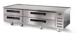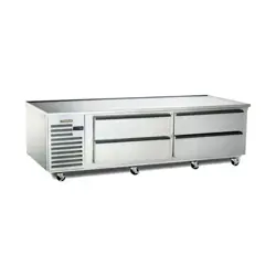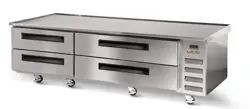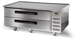
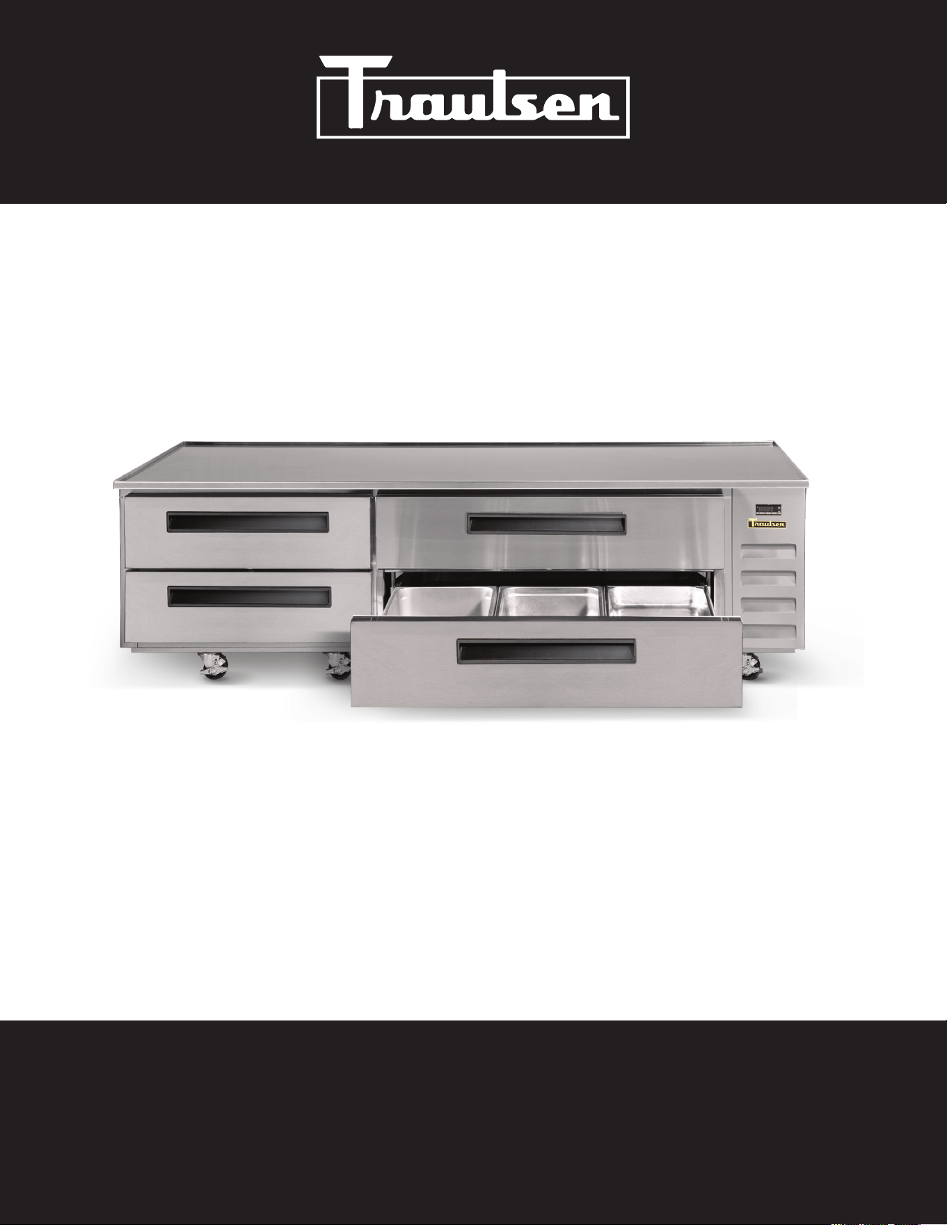
C-SERIES EQUIPMENT STANDS (CLES)
Hours of Operation: Monday - Friday 7:30 a.m. - 4:30 p.m. (CST)
4401 Blue Mound Road Fort Worth, Texas 76106 (USA)
Phone: 800.825.8220 | Service Fax: 817.740.6757 | E-mail: [email protected] | Website: traulsen.com
OWNER’S MANUAL
*Please Note: This manual is intended for use with the above referenced equipment manufactured after AUgust 2026. Traulsen’s equipment stands are
solely intended for use with cooking equipment. To obtain a copy of the correct Owner’s Manual to support the same products manufactured prior to this
date, please contact Traulsen Service at (800) 825-8220.
-1-
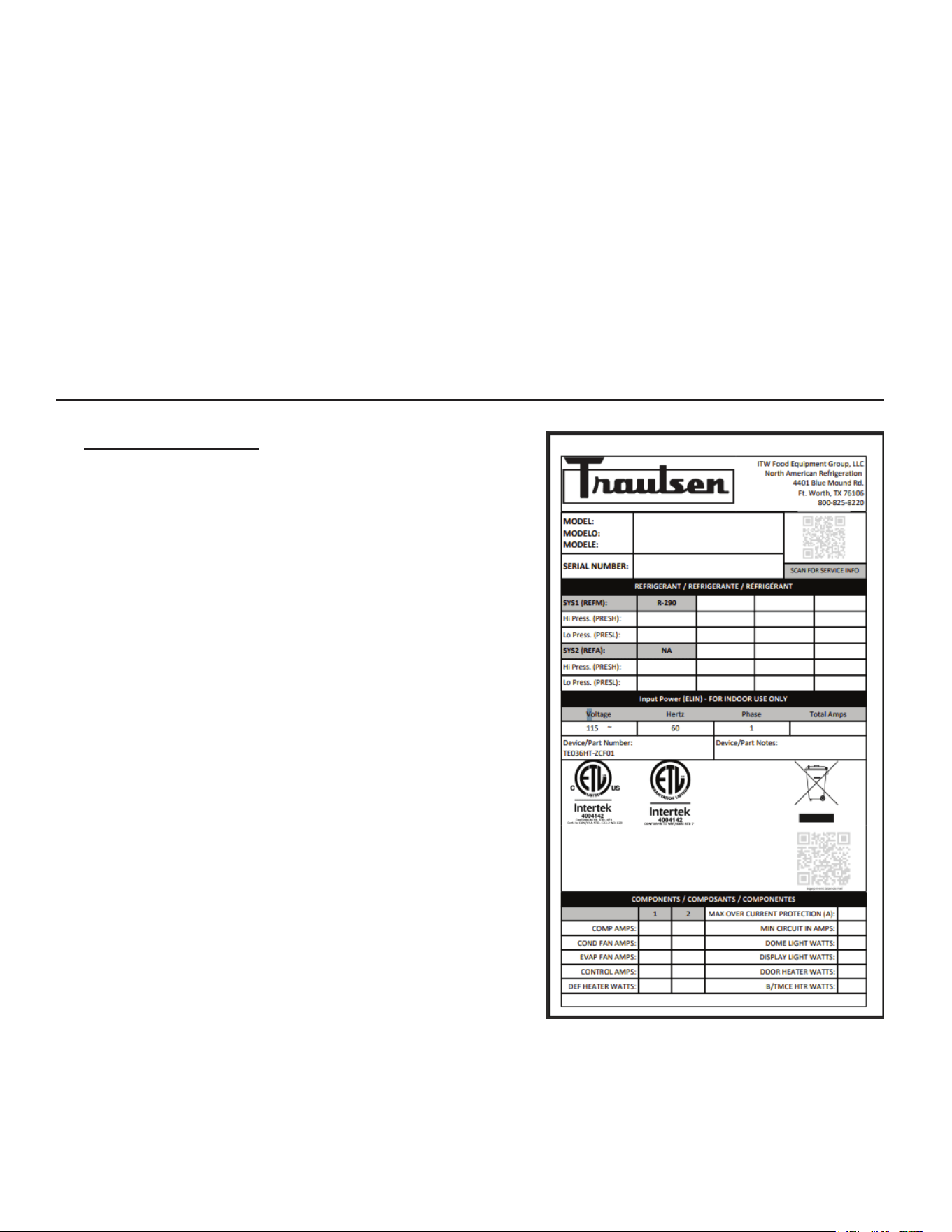
I. THE SERIAL TAG Page 1
II. RECEIPT INSPECTION Page 2
III. INSTALLATION
a) Location Page 2
b) Packaging Page 2
c) Adjusting the Casters Page 2
d) Cord & Plug Page 2
e) Power Supply Page 2
f) Placing Equipment on Top of Unit Page 3
IV. OPERATION Page 3
V. CARE & MAINTENANCE
a) Cleaning the Condenser Filter Page 3
b) Replacing the Gaskets Page 3
c) Cleaning the Cabinet Surface Page 4
VI. DRAWERS
a) Removing Drawers/Frame Modules Page 4
VII. MICROPROCESSOR CONTROL
a) Information Menu Page 4
b) Adjusting Cabinet Setpoint Page 4
c) Initiating a Defrost Page 5
d)CongurationParameters Page5
e) Technical Data Page 5
f) Components & Wiring Diagram Page 10
VIII. TROUBLE SHOOTING GUIDE Page 11
IX. SERVICE/WARRANTY INFORMATION
a) Service Information Page 12
b) Spare Parts Information Page 13
c) Warranty Registration Page 13
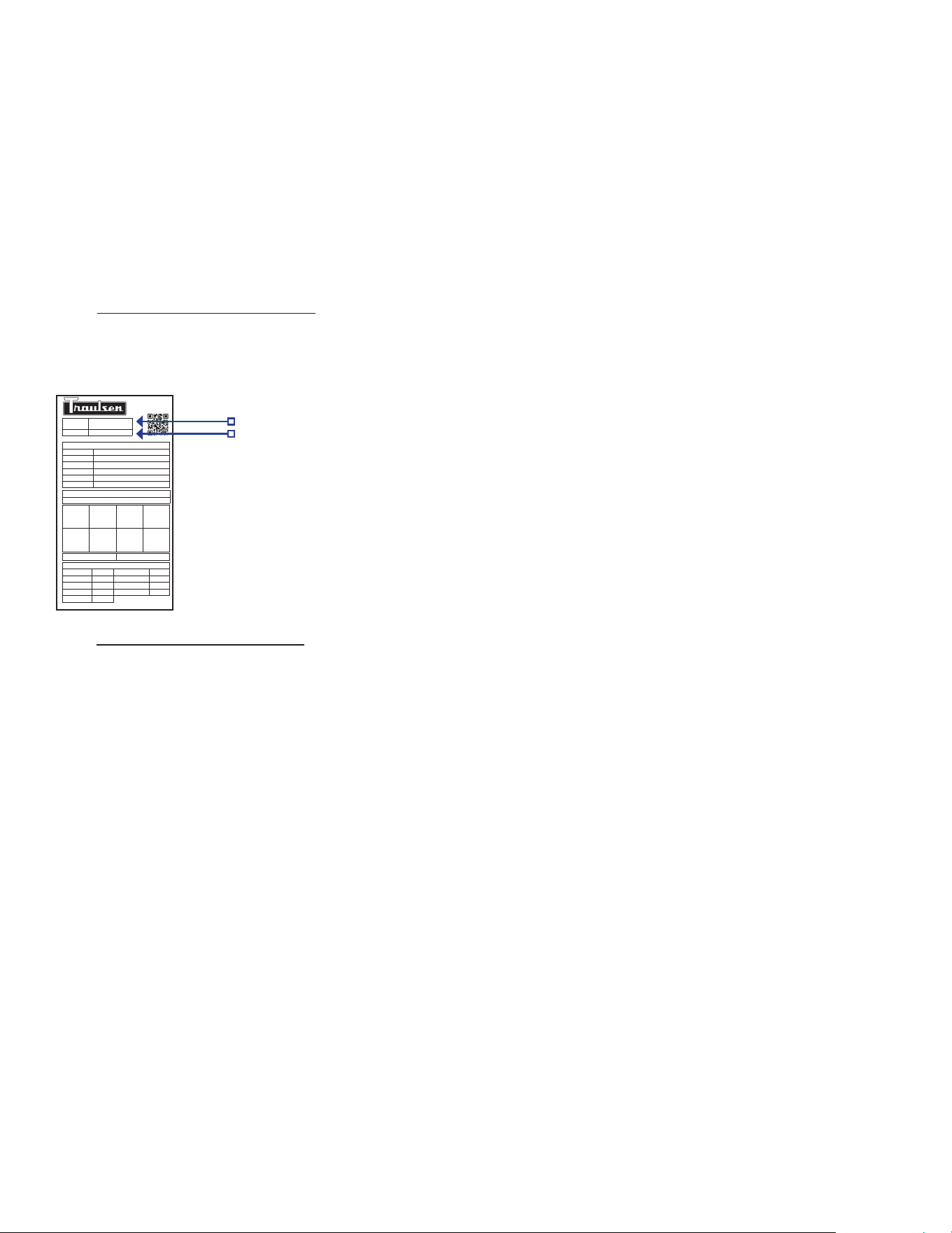
I. THE SERIAL TAG
Theserialtagisapermanentlyaxedlabelonwhichisrecorded
vital electrical and refrigeration data about your Traulsen product,
as well as the model and serial number. This tag is located in
the right interior compartment on all standard equipment stand
models.
READING THE SERIAL TAG
• Serial = The permanent ID# of your Traulsen unit
• Model = The model # of your Traulsen unit
• Volts = Voltage
• Hz = Cycle
• PH = Phase
• Total Current = Maximum amp draw
• Minimum Circuit = Minimum circuit ampacity
• Lights = Light wattage
• Heaters = Heater amperage (hot food units only)
• Refrigerant = Refrigerant type used
• Design Pressure = High & low side operating pressures and
refrigerant charge
• Agency Labels = Designates agency listings
CLES-36HT
26H
-2-
II. RECEIPT INSPECTION
All Traulsen products are factory tested for performance
and are free from defects when shipped. The utmost care
has been taken in crating this product to protect against
damage in transit.
You should carefully inspect your Traulsen unit for damage
during delivery. If damage is detected, you should save all
the crating materials and make note on the carrier’s Bill Of
Lading describing the damage. A freight claim should be
ledimmediately.Ifdamageissubsequentlynotedduringor
immediately after installation, contact the respective carrier
andleafreightclaim.Thereisave(5)daylimit tole
freight damage with the carrier. Under no condition may a
damagedunitbereturnedtoTraulsenwithoutrstobtaining
written permission (return authorization). You may contact
Hobart/Traulsen customer care at 800-333-7447 to request
a return.
Systems Using Refrigerant R-290 (Propane)
Traulsen has selected propane as the refrigerant for many
of their products. In addition to its low global warming
potential and impact on the environment, propane is an
ideal refrigerant. It is a ammable refrigerant, however,
whichiswhyyouwillseea“ammablerefrigerant”sticker
on applicable products. Traulsen products using propane
as the refrigerant are UL approved and are safe to use in
accordance with this Owner’s Manual and general industry
practices for commercial cooking environments. Please
check with local codes or regulations for any restrictions to
products using hydrocarbon refrigerants.
III. INSTALLATION
III. a) LOCATION
Unitmustbeplacedonleveloorforproperuse.
III. b) PACKAGING
Your Traulsen unit was shipped from the factory packaged
with stretch wrap material.
Most exterior stainless steel surfaces have a protective blue
vinyl covering to prevent scratching during manufacturing,
shipping and installation. After the unit is installed in place
of application peel, remove and discard the covering from
all surfaces.
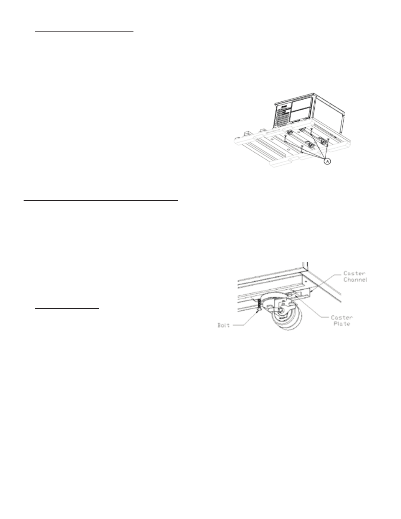
The equipment stands are shipped on a skid that is designed
toallowaunittobeslidotheskidontothefactoryinstalled
casters. When a unit is being removed from the skid two or
more runners will act as slides and will remain with the unit
while it is being removed. These runners prevent damage to
themachinewhenitdropsotheskidtotheoor.
III. b) PACKAGING CONT’D
To unload the machine, remove the exterior packaging.
Next, remove the bolts that attach the skid to the machine
as shown in (A).
Finally, push the machine o the skidkeeping the length
of the machine parallel to the skid’s 4x4 pieces. On longer
machines this may require two or more individuals.
NOTE: Traulsen does not recommend laying the unit on
its front, side or back. If you must, please allow the unit to
remain in an upright position for 24 hours before plugging
it in so that the compressor oils and refrigerant may settle.
III. c) ADJUSTING THE CASTERS
To adjust the caster loosen the two bolts and move caster
to desired location, spacing between casters not to exceed
48 inches. Casters on each end of the unit can not exceed
8 inches from the end of the cabinet.
III. d) CORD & PLUG
All self-contained models are shipped standard with a NEMA
5-15P plug and 9 foot cord and spring retainer attached at
the rear of the cabinet. Select only a dedicated electrical
outlet for power source.
NOTE: Do not under any circumstances, cut or remove the
round grounding prong from the plug, or use an extension
cord.
III. e) POWER SUPPLY
The supply voltage should be checked prior to connection
to be certain that proper voltage for the cabinet wiring
is available (refer to the serial tag to determine correct
unit voltage). Make connections in accordance with local
electricalcodes.Usequaliedelectricians.
-3-
III. e) POWER SUPPLY CONT’D
Use of a separate, dedicated circuit is required. Size wiring
to handle indicated load and provide necessary over current
protector in circuit (see amperage requirements on the unit’s
serial tag).
III. f) PLACING EQUIPMENT ON TOP OF UNIT
Equipment may be placed on top of your Traulsen equipment
stand. A stainless steel worktop, provided standard is
required on cabinets being used to support equipment
weighing in excess of 100 lbs. or producing heat in excess of
140°F to the top surface. Refer to below chart to determine
maximum top load capacity for your unit.
MODEL MAX TOP LOAD CAPACITY (lb.)
CLES-36HT 700 MH
CLES-48HT 700 MH
CLES-60HT 1,200 MH
CLES-72HT 1,200 MH
CLES-84HT 1,500 MH
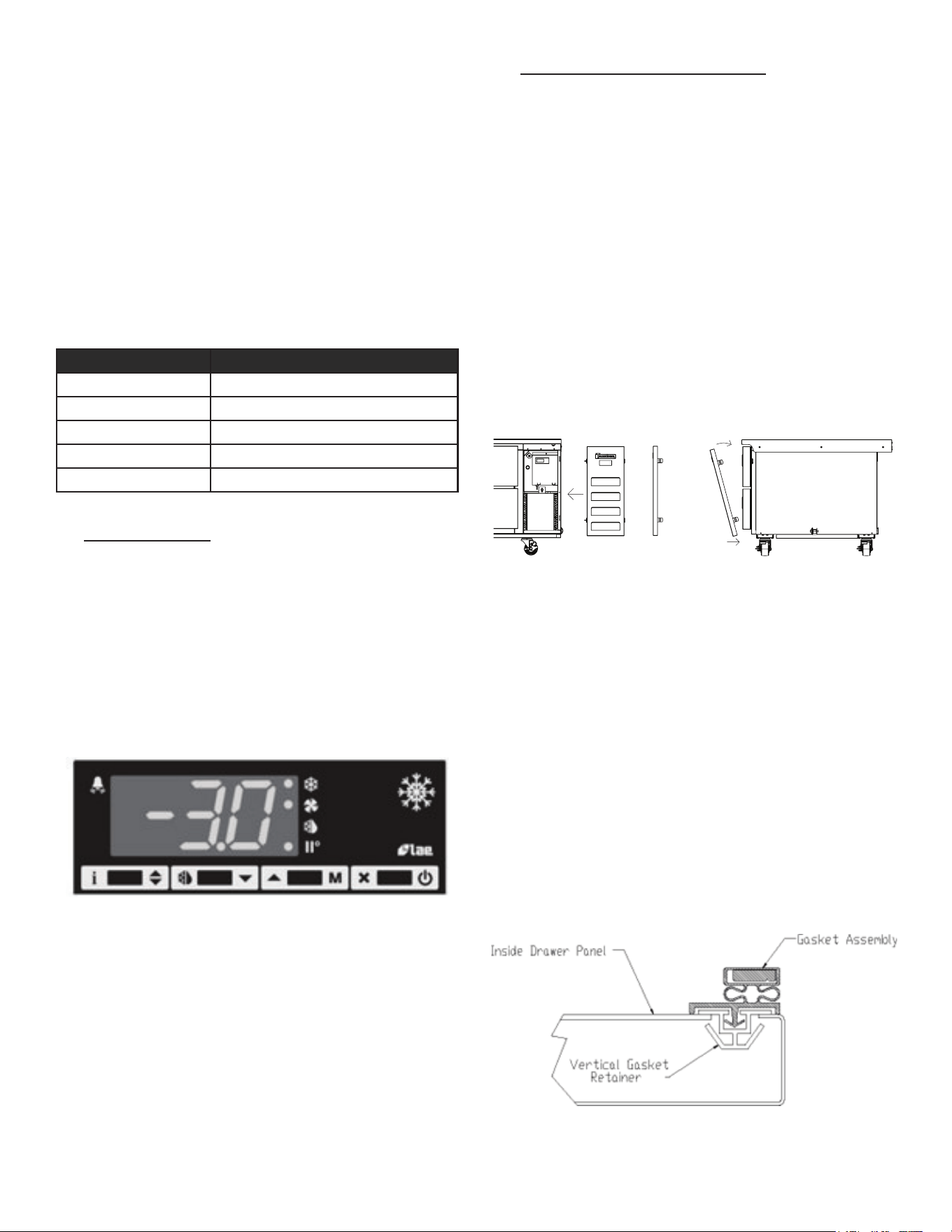
IV. OPERATION
Refrigerators do not require manual defrosting. During
normal operation, a refrigerator continuously circulates
above freezing cabinet air through the coil. A compressor
“OFF” cycle occurs every 2-1/2Hours for 20 minutes to
melt any frost which may accumulate on the coil during
thecompressor“ON”cycle.Thecontrolwillreadsetpoint
temperature, and the half water-half snowflake will be
illuminated. With standard holding refrigerators, high relative
humidity is also maintained to prevent dehydration of stored
product.
V. CARE & MAINTENANCE
V. a) CLEANING THE CONDENSER FILTER
The most important thing you can do to ensure a long,
reliable service life for your Traulsen is to regularly clean
thecondensercoilandorlterifprovided.
WARNING: DISCONNECT ELECTRICAL POWER SUPPLY
BEFORE
CLEANING ANY PARTS OF THE UNIT.
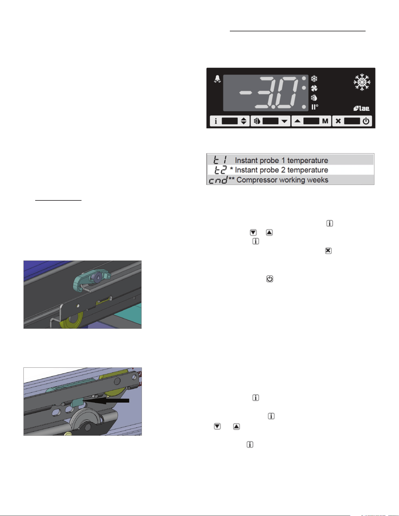
Tocleanthecondenser/lter,rstdisconnectelectricalpower
to the cabinet and remove the front louver assembly. To do
so, place hands under the louver panel and pull out and up
togetlouverpanelobracketoftheunit.Seediagrambelow.
Systems Using Refrigerant R-290 (Propane)
Removeanyignitionsource(arc,ame,heat)beforecleaning
the condenser coil. If the condenser coil is inadvertently
damaged during cleaning to the point of causing a refrigerant
leak, immediately ventilate the area and call for service.
Proceed to vacuum or brush any dirt, lint or dust from the
nnedcondensercoil/lter,thecompressorandothercooling
systemparts.Ifsignicantdirtiscloggingthecondenserns
orlter,usecompressedairtoblowthisclear.Toreplacethe
louver assembly reverse the process.
V. b) REPLACING THE GASKETS
Toremovethegaskettobereplaced,graspitrmlybyone
corner and pull it out. Before attempting to install a new
gasket, both the unit and the gasket itself must be at room
temperature.Insertthefourcornersrstbyusingarubber
mallet (or hammer with a block of wood). After the corners
are properly inserted, work your way towards the center from
both ends by gently hitting with a mallet until the gasket is
completely seated in place (see below for proper gasket
placement).
NOTE: The gasket may appear too large, but if it is installed
as indicated above it will slip into place.
-4-
V. c) CLEANING THE CABINET SURFACE
WARNING: DISCONNECT ELECTRICAL POWER SUPPLY
BEFORE
CLEANING ANY PARTS OF THE UNIT.
Exterior stainless steel should be cleaned with warm water,
mild soap and a soft cloth. Apply with a dampened cloth and
wipe in the direction of the metal grain.
Avoid the use of strong detergents and gritty, abrasive
cleaners as they may tend to mar and scratch the surface.
Do NOT use cleansers containing chlorine, such as bleach,
this may promote corrosion of the stainless steel.
Care should also be taken to avoid splashing the unit with
water, containing chlorinated cleansers, when mopping the
ooraroundtheunit.
For stubborn odor or spills, use baking soda and water
(mixed to a 1 tbsp baking soda to 1 pint water ratio).
A stainless steel polish is recommended for shining of unit.
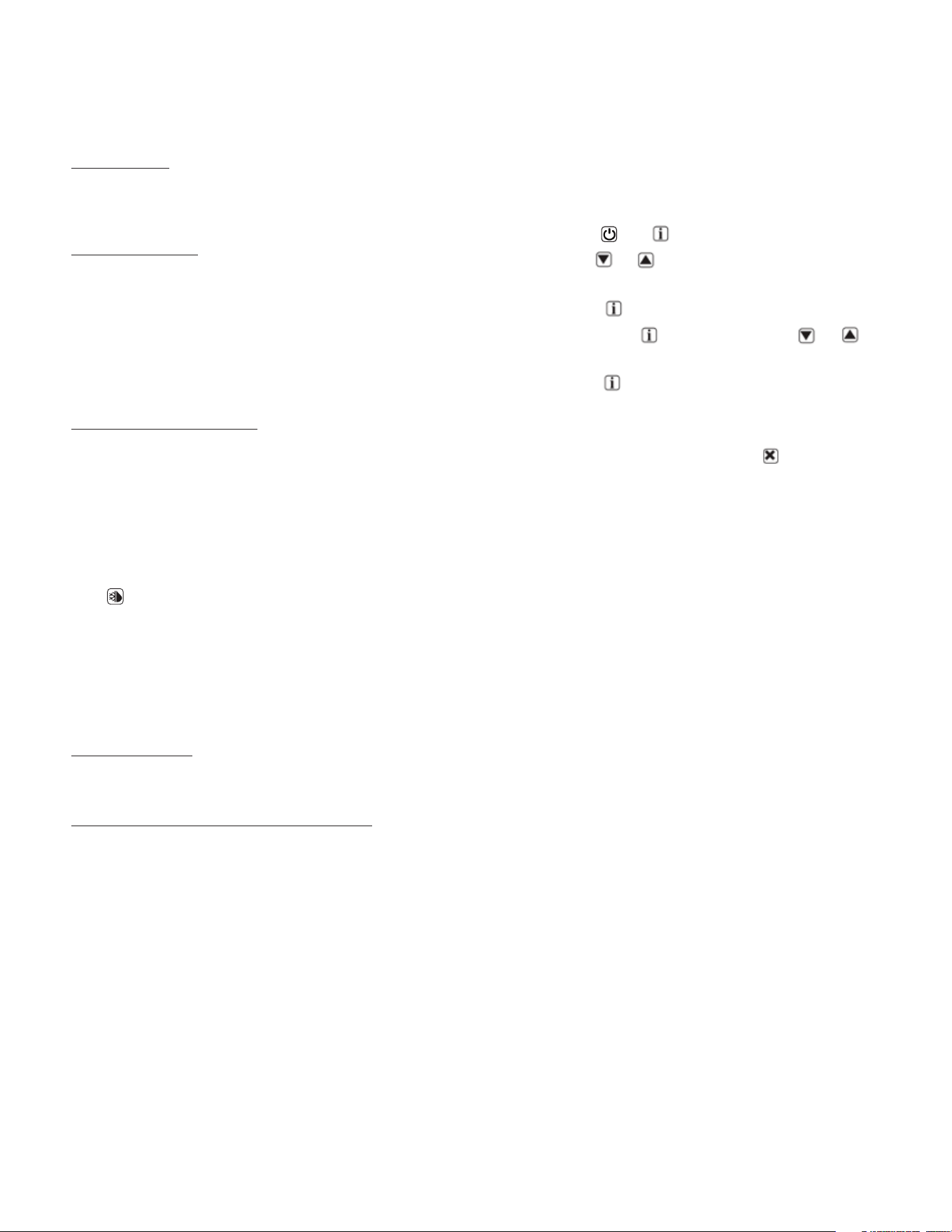
VI. DRAWERS
Drawermodelinteriorttingsmayrequireatooltofacilitate
cleaning. The drawer frame may be removed without tools.
To remove the drawers, the lock tab must be unlocked by
sliding the lock tab forward and then up, to loosen the slides
(seegurebelow).Thenthedrawercanbepulledouteasily
from the slides.
To remove the middle slide between the drawer and cabinet
for deeper cleaning, remove the middle slide by lifting up on
thebacktabandslidingitoutofthetrack(seegurebelow).
Caution: The outer slides attached the side of the cabinet
should not be removed because there are washers set
in the assemble to hold the proper spacing between the
slides. If removed the drawer slides may not function
properly.
VII. MICROPROCESSOR CONTROL
Your new equipment stand is equipped with a digital
control, which precisely regulates operation. It is supplied
from the factory completely ready for use.
VII. a) INFORMATION MENU
The information available in this menu is:
* displayed only if enabled (see Configuration Parameters)
** displayed only if ACC > 0
Access to menu and information displayed:
• Press and immediately release button .
• With button or select the data to be displayed.
• Press button to display value.
• To exit from the menu, press button or wait for 10
seconds.
Initiate Stand-By:
Keeping the button pressed for 3 seconds allows the
controller to be put on a standby or output control to be
resumed (with SB=YES only).
Locking the Keypad:
The keypad lock avoids undesired, potentially dangerous
operations, which might be attempted when the controller
is operating in a public place. In the INFO menu, set
parameter LOC = YES to inhibit all functions of the buttons.
To resume normal operation of keypad, adjust setting so
that LOC = NO.
VII. b) ADJUSTING CABINET SETPOINT
Setpoint display and modification:
• Press button for at least a half second to display
the setpoint value.
• While keeping the button pressed, use button
or to set the desired value (adjustment is within
the minimum SPL and the maximum SPH limit).
When button is released, the new value is stored.
Drawer lock tab
shown in unlocked
position.
-5-
VII. c) INITIATING A DEFROST
Automatic defrost:
Defrost starts automatically as soon as the time set with
parameter DFT has elapsed.
• Timed defrost: With DFM = TIM defrosts take place at
regular intervals when the timer reaches the value
of DFT. For example, with DFM = TIM and DFT = 36, a
defrost will take place every 6 hours.
• Optimized defrost: With DFM = FRO the timer is only
increased when the conditions occur for frost to form
on the evaporator, until the time set with parameter
DFT is matched. If the evaporator works at 0°F, defrost
frequency depends on the thermal load and climatic
conditions. With setpoints much lower than 0°F,
defrost frequency mainly depends on the refrigerator
operating time.
• Defrost time count backup: At the power-up, if DFB =
YES, the defrost timer resumes the time count from
where it was left o before the power interruption.
Vice versa, with DFB = NO, the time count re-starts
from 0. In stand-by, the accumulated time count is
frozen.
Manual or remote defrost start:
It’s possible to manually start a defrost, by pressing
button for 2 seconds.
Defrost type. Once defrost has started, Compressor and
Defrost outputs are controlled according to parameter
DTY. If FID = YES, the evaporator fans are active during
defrost.
Defrost termination. The actual defrost duration is
influenced by a series of parameters.
• Time termination: T2 = NO and T3 dierent from 2EU:
the evaporator temperature is not monitored and
defrost will last as long as time DTO.
• Temperature monitoring of one evaporator: T2 = YES
and T3 dierent from 2EU. In this case, if the sensor
T2 measures the temperature DLI before the time DTO
elapses, defrost will be terminated in advance.
Resuming thermostatic cycle:
When defrost is over, if DRN is greater than 0, all outputs
will remain o for DRN minutes, in order for the ice to melt
completely and the resulting water to drain. Moreover, if
probe T2 is active (T2 = YES), the fans will re-start when
the evaporator gets to a temperature lower than FDD; Vice
versa, if probe T2 is not active (T2 = NO) or after defrost
has come to an end, such condition does not occur by end
of the time FTO, after FTO minutes have elapsed the fans
will be switched on anyway.
VII. c) INITIATING A DEFROST CONT’D
Caution: if DFM = NON or C-H = HEA all defrost functions
are inhibited; if DFT = 0, automatic defrost functions are
excluded.
VII. d) CONFIGURATION PARAMETERS
Parameter Configuration:
• To get access to the parameter configuration menu,
press button
and for 5 seconds.
• With button or select the parameter to be
modified.
• Press button to display the value.
• By keeping button pressed, use button or to
set the desired value.
• When button is released, the newly programmed
value is stored and the following parameter is
displayed.
• To exit from the setup, press button or wait for 30
seconds.
VII. e) TECHNICAL DATA
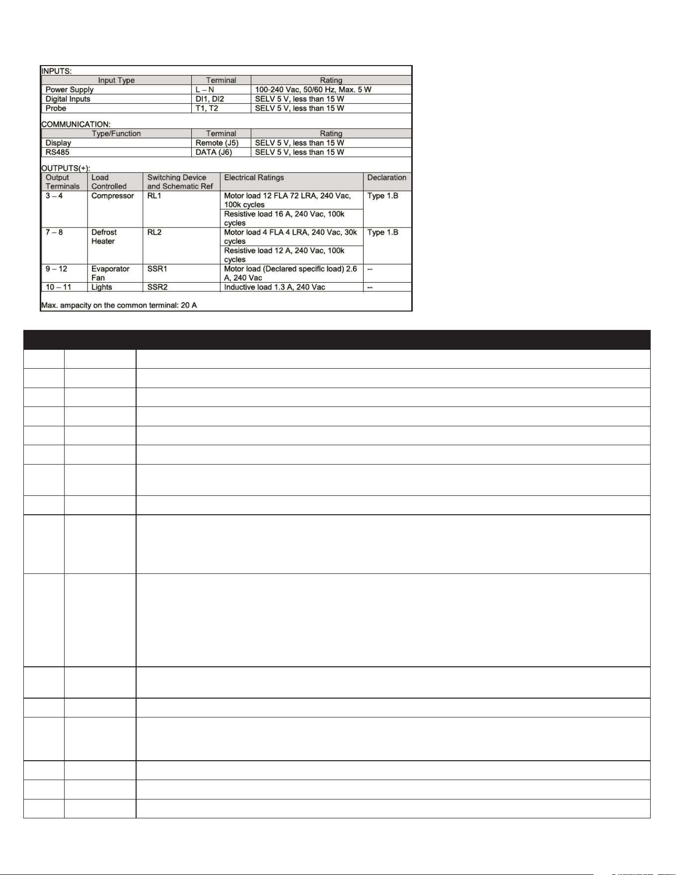
Power supply
100-240Vac ±10%, 50/60Hz, 3W
Relay output max loads (240Vac)
-6-
VII. e) TECHNICAL DATA CONT’D
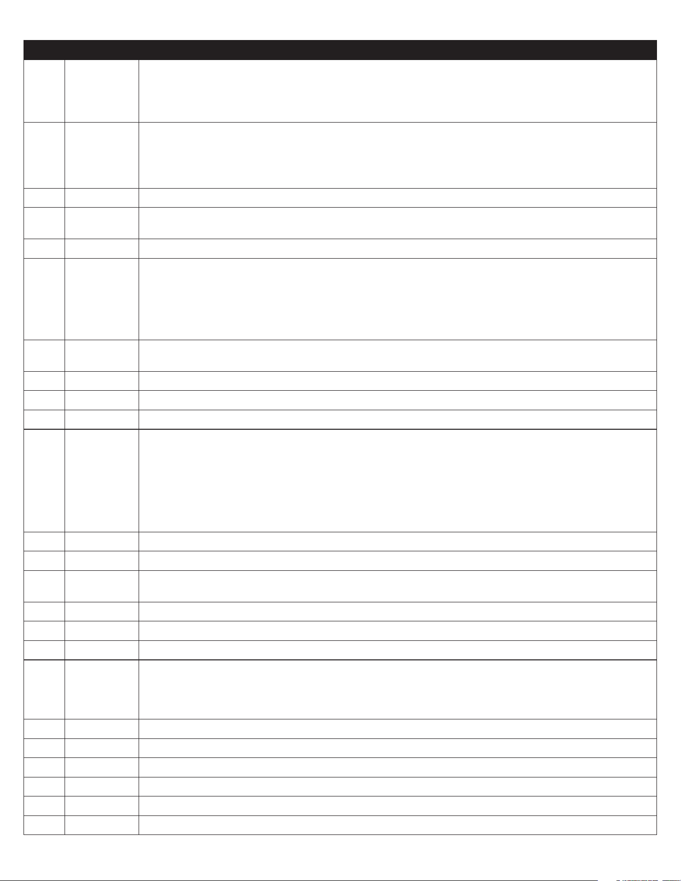
PAR RANGE DESCRIPTION
SPL -58..SPH Minimum limit for SP setting.
SPH SPL...180° Maximum limit for SP setting.
SP SPL... SPH Setpoint (value to be maintained in the room).
C-H REF; HEA Refrigerating (REF) or Heating (HEA) control mode.
HY0 1...10° Thermostat OFF -> ON dierential.
HY1 0...10° Thermostat ON -> OFF dierential.
CRT 0...30min Compressor rest time. The output is switched on again after CRT minutes have elapsed since the
previous switchover. We recommend to set CRT=03 with HY0<2.0°.
CT1 0...30min Compressor/Heater output run when probe T1 is faulty. With CT1=0 the output will always remain OFF.
CT2 0...30min Compressor/Heater output stop when probe T1 is faulty. With CT2=0 and CT1>0 the output will always
be ON.
Example: CT1=4, CT2= 6: In case of probe T1 failure, the compressor will cycle 4 minutes ON and 6
minutes OFF.
DFM NON;
TIM;
FRO
CRN
Defrost start mode
NON : defrost function is disabled (the following parameter will be FCM).
TIM : regular time defrost.
FRO : the defrost time count is only increased when the conditions occur for frost to form on the
evaporator (optimized time increase).
CRN : defrost is based o of compressor run time (time is based o of DAT).
DFT 0...250 Time interval among defrosts in x10 minutes. When this time has elapsed since the last defrost, a new
defrost cycle is started. Each number is multiplied by 10 minutes. 0-250 indicates 0-2500 minutes.
DAT 0…100hrs Frost accumulation timeout.
DFB NO/YES Defrost timer backup. With DFB=YES, after a power interruption, the timer resumes the count from where
it was left o with ±30 min. approximation. With DFB=NO, after a power interruption, the defrost timer
will re-start to count from zero.
DLI -58...180° Defrost end temperature.
DMD 0…30min Minimum defrost duration.
DTO 1...120min Maximum defrost duration.
-7-
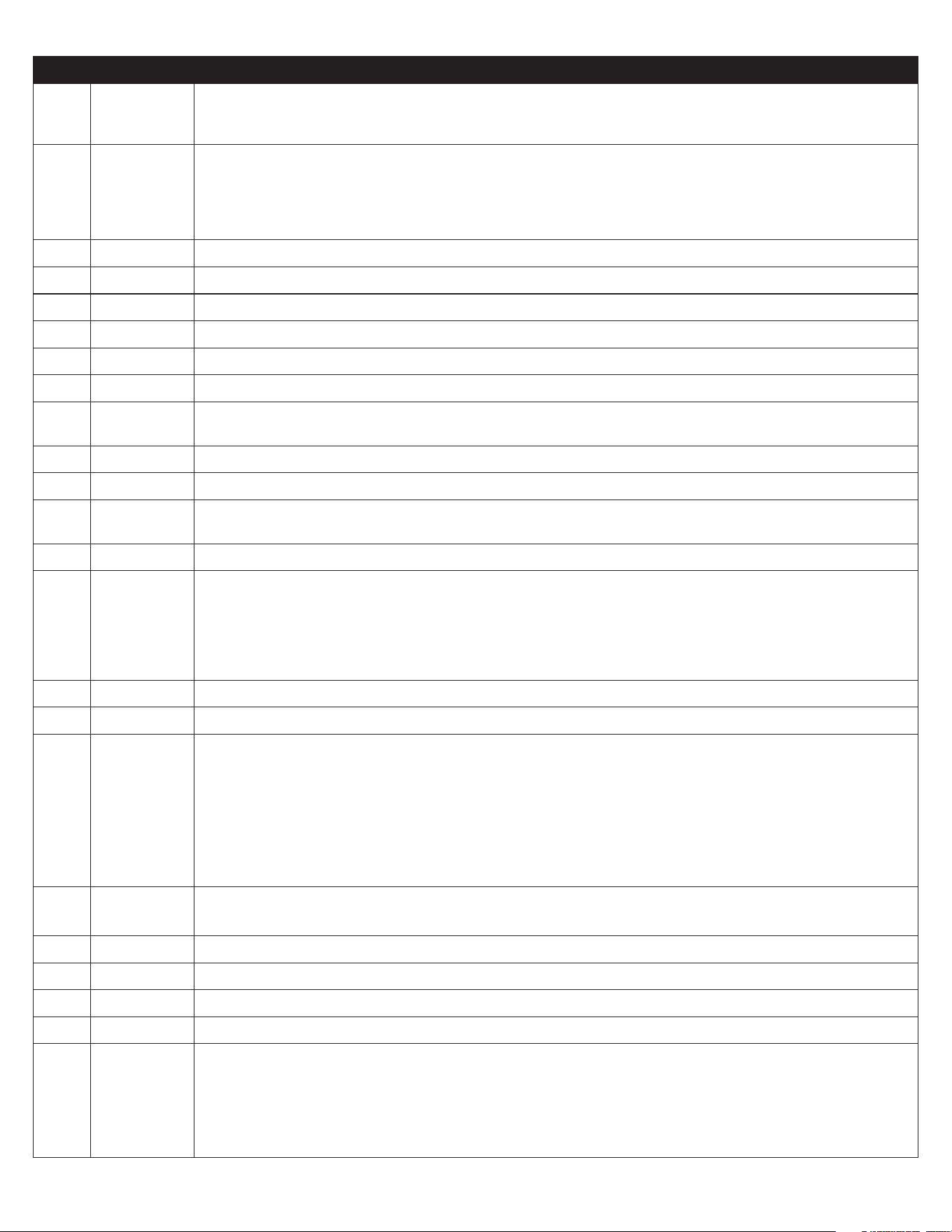
PAR RANGE DESCRIPTION
DTY OFF; ELE;
GAS
Defrost type
OFF: o cycle defrost (Compressor and Heater OFF). ELE: electric defrost (Compressor OFF and Heater
ON). GAS: hot gas defrost
(Compressor and Heater ON).
DSO OFF;
LO;
HI
Defrost start optimization
OFF : no optimization.
LO : defrost waits until the compressor cut-out.
HI : defrost waits until the compressor cut-in.
SOD 0...30 min Start optimization delay.
DPD 0...240sec Evaporator pump down. At the beginning of defrost, defrost outputs (determined by DTY) are OFF for
DPD seconds.
DRN 0...30min Pause after defrost (evaporator drain down time).
DDM RT;
LT;
SP;
DEF
Defrost display mode. During defrost the display will show:
RT: the real temperature;
LT : the last temperature before defrost;
SP : the current setpoint value;
DEF : “dEF”.
DDY 0...60min Display delay. The display shows the information selected with parameter DDM during defrost and for
DDY minutes after defrost termination.
FID NO/YES Fans active during defrost.
FDD -58...180° Evaporator fan re-start temperature after defrost.
FTO 0...120min Maximum evaporator fan stop after defrost.
FCM NON;
TMP;
TIM
Fan mode during thermostatic control.
NON : The fans remain ON all the time;
TMP : Temperature-based control. The fans are ON when the compressor is ON. When the compressor
is turned OFF, the fans remain ON as long as the temperature dierence Te-Ta is greater than FDT. The
fans are turned ON again with FDH dierential. (Te = Evaporator temperature, Ta = Air temperature);
TIM : Timed-based control. The fans are ON when the compressor is ON. When the compressor is OFF,
the fans switch ON and OFF according to parameters FT1, FT2,FT3
FDT -12...0° Evaporator-Air temperature dierence for the fans to turn OFF after the compressor has stopped.
FDH 1...12° Temperature dierential for fan re-start.
Example: FDT = -1, FDH=3. In this case, after the compressor has stopped, the fans are OFF when Te >
Ta - 1 (FDT), whereas the fans are ON when Te < Ta - 4 (FDT-FDH).
FT1 0...180sec Fan stop delay after compressor/heater stop. See Fig. 2
FT2 0...180 Timed fan stop in x10 seconds. With FT2=0 the fans remain on all the time.
FT3 0...180 Timed fan run in x10 seconds. With FT3=0, and FT2 > 0, the fans remain o all the time.
ATM NON;
ABS;
REL
Alarm threshold management.
NON : all temperature alarms are inhibited (the following parameter will be ACC).
ABS : the values programmed in ALA and AHA represent the real alarm thresholds.
REL : the alarm threshold is obtained by the sum of setpoint, thermostat dierential and ALR/AHR.
ALA -58... 180° Low temperature alarm threshold.
AHA -58... 180° High temperature alarm threshold.
ALR -12... 0° Low temperature alarm dierential. With ALR=0 the low temperature alarm is excluded.
AHR 0... 12° High temperature alarm dierential. With AHR=0 the high temperature alarm is excluded.
ATI T1; T2; T3 Probe used for temperature alarm detection.
ATD 0... 120 min Delay before alarm temperature warning.
-8-
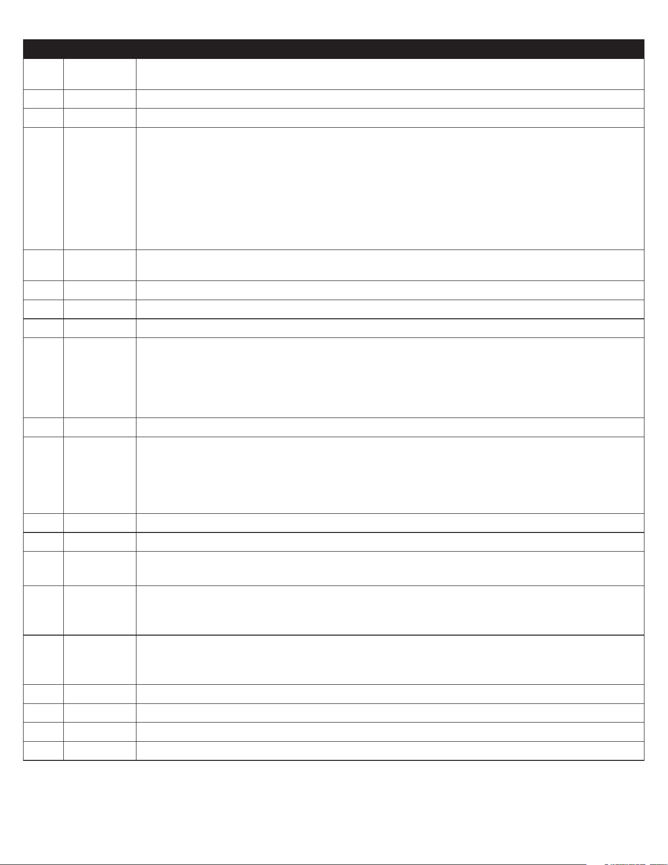
PAR RANGE DESCRIPTION
ACC 0...52 weeks Condenser periodic cleaning. When the compressor operation time, expressed in weeks, matches the ACC
value programmed, “CL” flashes in the display. With ACC=0 the condenser cleaning warning is disabled
and CND disappears from Info Menu.
IISM NON;
MAN;
ECO;
DI
Switchover mode to second parameter set
NON : inhibition to use the second parameter group (the following parameter will be SB).
MAN : button switches the two parameter groups over.
ECO : automatic switchover to the second parameter group, when ECO conditions are detected.
DI : switchover to the second parameter group when DIx input is on.
IISL -58... IISH Minimum limit for IISP setting.
IISH IISL... 180° Maximum limit for IISP setting.
IISP IISL... IISH Setpoint in mode 2.
IIH0 1... 10° Thermostat OFF->ON dierential in mode 2.
IIH1 0... 10° Thermostat ON->OFF dierential in mode 2.
IIDF 0...250 Time interval among defrosts in mode 2 in x10 minutes.
IIFC NON;
TMP; TIM
Fan control in mode 2. See FCM.
ECS 1...5 Controller sensitivity for the automatic switchover from Group I to Group II (1=minimum, 5=maximum).
ECS 1…5 Controller sensitivity for the automatic switchover.
EPT 0...240 min Eco pull-down time. Only with IISM=ECO. Group I parameters are used in regulation for at least EPT
minutes. See Fig.3
SB NO/YES Stand-by button enabling.
DSM NON;
ALR;
STP
Door switch input mode:
NON : door switch inhibited
ALR : when DIx=DOR and the digital input is on, an alarm is generated after ADO minutes
STP : when DIx=DOR and the digital input is on, in addition to the alarm, the fans are immediately
stopped and the compressor is stopped after CSD minutes.
DAD 0...30 min Delay before door open alarm warning.
CSD 0...30 min Compressor/heater stop delay after door has been opened.
D1O NON;
DOR;
ALR;
IISM;
RDS
DI1 digital input operation
NON : digital input 1 not active.
DOR : door input.
ALR : when the input is on, an alarm is generated (if AHM=STP, the compressor is stopped and the
defrosts are suspended).
IISM : when the input is on, the controller will use group 2 parameters.
RDS : when the input is on, a defrost is started (remote control).
D1A OPN; CLS. DI1 digital input activation.
OPN : on open CLS : on close
D2O See D1O DI2 digital input operation. See D1O.
D2A OPN; CLS. DI2 digital input activation. OPN : on open CLS : on close
PSL -58…158 Minimum setpoint adjusted via potentiometer.
PSR 0…15 Range of setpoint adjusted via potentiometer.
LSM NON;
MAN;
ECO;
DI1;
DI2; DI3.
Light control mode
NON : light output not controlled.
MAN : light output controlled through button (if OAx=LGT).
ECO : lights activated/deactivated following the ECO state.
DIx : lights activated/deactivated following the DIx state.
-9-
PAR RANGE DESCRIPTION
LSA OPN; CLS Light activation (only with LSM=ECO or LSM=DIx). OPN : lights on with DIx open or ECO mode
deactivated. CLS : lights on with DIx closed or ECO mode activated.
OT1 0…600 sec Activation time of OA1
OT2 0…600 sec Pause between OA1 activation
OA1 NON;
LGT;
0-1;
2CU;
2EU;
ALO;
ALC
AUX 1 output operation
NON : output disabled (always o).
LGT : output enabled for light control.
0-1 : the relay contacts follow the on/standby state of controller.
2CU : output programmed for the control of an auxiliary compressor.
2EU : output enabled for the control of the electrical defrost of a second evaporator.
ALO : contacts open when an alarm condition occurs.
ALC : contacts make when an alarm condition occurs.
2CD 0...120 sec Auxiliary compressor start delay. If OAx=2CU the auxiliary output is switched on with a delay of 2CD
seconds after the main compressor has cut-in. Both compressors are turned o at the same time.
OS1 -12.5..12.5° Probe T1 oset.
T2 NO/YES Probe T2 enabling (evaporator).
OS2 -12.5..12.5° Probe T2 oset.
T3 NON;
DSP;
CND;
2EU
Auxiliary probe T3 operation
NON : probe T3 not fitted.
DSP : temperature T3 to be displayed.
CND : condenser temperature measurement.
2EU : second evaporator temperature measurement.
OS3 -12.5..12.5° Probe 3 oset.
AHM NON;
ALR;
STP;
Operation in case of high condenser alarm
NON : high condenser alarm inhibited.
ALR : in case of alarm, “HC” flashes in the display and the buzzer is switched on.
STP : in addition to the alarm symbols displayed, the compressor is stopped and defrosts are
suspended.
AHT -50...110° Condensation temperature alarm (referred to T3 probe).
TLD 1...30 min Delay for minimum temperature (TLO) and maximum temperature (THI) logging.
TDS T1;
1-2; T3
Selects the temperature probe to be displayed. T1 : probe T1
1-2 : the AVG-weighted average between T1 and T2 T3 : probe T3
AVG 0...100% The relative weight of T2 on T1 (if TDS = 1-2)
Example 1: T1 = -5°, T2 = -20°, AVG = 100%. The displayed temperature will be -20° (T1 has no eect)
Example 2: T1 = -5°, T2 = -20°, AVG = 60%. The displayed temperature will be -14.
SCL 1°C;
2°C;
°F
Readout scale.
1°C : measuring range -50…110°C (0.1°C resolution within -9.9 ÷ 19.9°C interval, 1°C outside)
2°C : measuring range -50 … 110°C °F : measuring range -55 … 180°F
SIM 0...100 Display slowdown.
ADR 1...255 TRL-002 address for PC communication.
NPR 0…1 Setup programmed.
STT 0…255 Setup traceability.
-10-
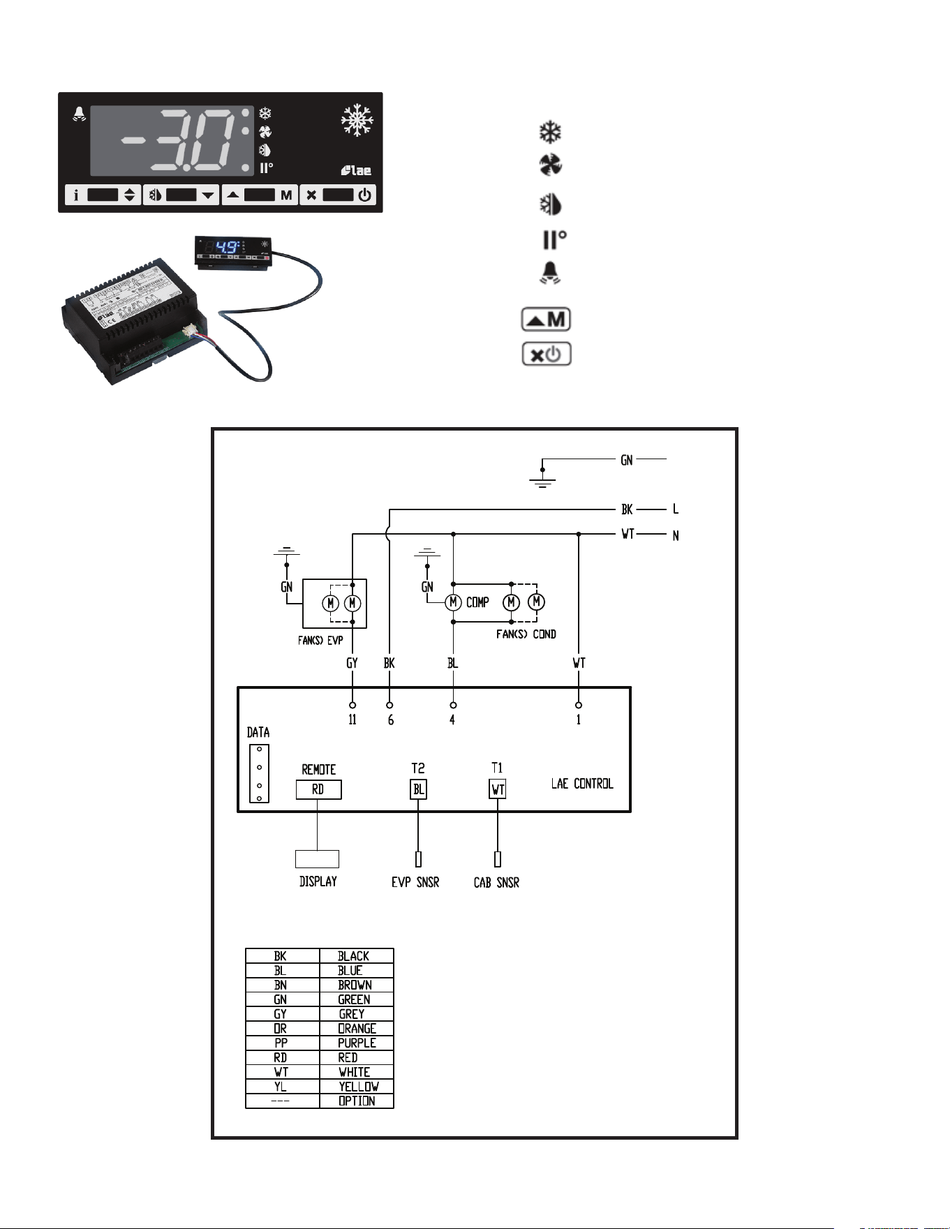
VII. f) COMPONENTS & WIRING DIAGRAM
Thermostat output
Fan output
Defrost output
Activation of 2
nd
parameter set
Alarm
Manual activation / Increase button
Exit / Stand-by button
Indications:
-11-
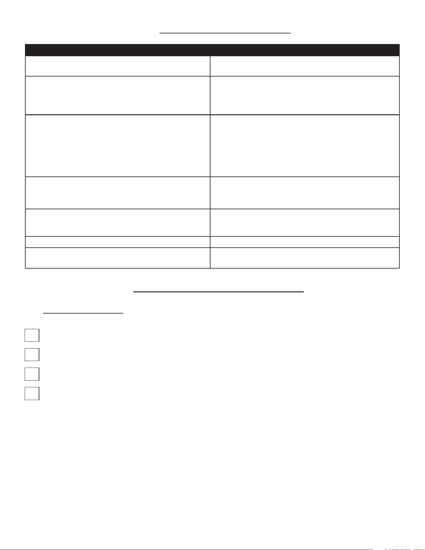
VIII. TROUBLESHOOTING GUIDE
FIND YOUR PROBLEM HERE REMEDY
1. Condensing unit fails to start.
a. Check if cord & plug has been disconnected.
b. Check control temperature setting.
2. Condensing unit operates for prolonged periods or continuously.
a. Are drawers closing properly?
b. Dirty condenser or filter. Clean properly.
c. Evaporator coil iced. Needs to defrost. See instructions for
setting a manual defrost cycle in section VII. c)
3. Food compartment is too warm.
a. Check drawers(s) and gasket(s) for proper seal
b. Perhaps a large quantity of warm food has recently been added
or the drawers were kept open for a long period of time, in both
cases, allow adequate time for the cabinet to recover its normal
operating temperature.
c. Control setting too high, readjust per instructions on section
VII. b)
d. Check that condensing coil is clean.
4. Food compartment is too cold.
a. Perhaps a large quantity of very cold or frozen food has recently
been added. Allow adequate time for the cabinet to recover its
normal operating temperature.
b. Adjust the control to a warmer setting, see section VII. b)
5. Condensation on the exterior surface.
a. Check drawer alignment and gaskets for proper seal.
b. Condensation on the exterior surface of the unit is perfectly
normal during periods of high humidity.
6. Compressor hums but does not start. a. Call for service.
7. No power to unit
a. Check if cord & plug has been disconnected.
b. Check power supply breaker.
IX. SERVICE/WARRANTY INFORMATION
IX. a) SERVICE INFORMATION
Before calling for service, please check the following:
Is the electrical cord plugged in?
Is the fuse OK or circuit breaker on?
Is the condenser coil clean?
Is the power switch on?
If after checking the above items and the unit is still not operating properly, please contact an authorized Traulsen service
agent:
4401 Blue Mound Road Fort Worth, TX 76106
(800) 825-8220.
Traulsen reserves the right to change specifications or discontinue models without notice.
-12-
This appliance is marked with the ISO 7010-W021 warning label to indicate the presence of FLAMMABLE REFRIGERANTS.
Prior to beginning work on systems containing FLAMMABLE REFRIGERANTS, safety checks are necessary to ensure that
the risk of ignition is minimized.
VENTILATED AREA
Ensure that the area is in the open or that it is adequately ventilated before breaking into the system or conducting any
hot work. A degree of ventilation shall continue during the period that the work is carried out. The ventilation should
safely disperse any released refrigerant and preferably expel it externally into the atmosphere.
CABLING
Check that cabling will not be subject to wear, corrosion, excessive pressure, vibration, sharp edges, or any other
adverse environmental eects. The check shall also take into account the eects of aging or continual vibration from
sources such as compressors or fans.
DETECTION OF FLAMMABLE REFRIGERANTS
Under no circumstances shall potential sources of ignition be used in the searching for or detection of refrigerant
leaks. A halide torch (or any other detector using a naked flame) shall not be used.
The following leak detection methods are deemed acceptable for all refrigerant systems. Electronic leak detectors may
be used to detect refrigerant leaks but, in the case of FLAMMABLE REFRIGERANTS, the sensitivity might not be
adequate, or might need recalibration. (Detection equipment shall be calibrated in a refrigerant-free area.) Ensure that
the detector is not a potential source of ignition and is suitable for the refrigerant used. Leak detection equipment
shall be set at a percentage of the LFL of the refrigerant and shall be calibrated to the refrigerant employed, and the
appropriate percentage of gas (25 % maximum) is confirmed.
Leak detection fluids are also suitable for use with most refrigerants but the use of detergents containing chlorine shall
be avoided as the chlorine can react with the refrigerant and corrode the copper pipe-work.
NOTE: Examples of leak detection fluids are
• bubble method
• fluorescent method agents
If a leak is suspected, all naked flames shall be removed/extinguished.
If a leakage of refrigerant is found which requires brazing, all of the refrigerant shall be recovered from the system,
or isolated (by means of shut o valves) in a part of the system remote from the leak. Removal of refrigerant shall be
according to the removal & evacuation section below.
REMOVAL & EVACUATION
When breaking into the refrigerant circuit to make repairs- or for any other purpose - conventional procedures shall
be used. However, for flammable refrigerants it is important that best practice be followed, since flammability is a
consideration. The following procedure shall be adhered to:
a) safely remove refrigerant following local and national regulations;
b) purge the circuit with inert gas;
c) evacuate
d) purge with inert gas;
e) open the circuit by cutting or brazing.
-13-
The refrigerant charge shall be recovered into the correct recovery cylinders if venting is not allowed by local and
national codes. For appliances containing flammable refrigerants, the system shall be purged with oxygen- free
nitrogen to render the appliance safe for flammable refrigerants. This process might need to be repeated
several times. Compressed air or oxygen shall not be used for purging refrigerant systems .
For appliances containing flammable refrigerants, refrigerants purging shall be achieved by breaking the vacuum in
the system with oxygen-free nitrogen and continuing to fill until the working pressure is achieved, then venting to
atmosphere, and finally pulling down to a vacuum. This process shall be repeated until no refrigerant is within the
system (optional for A2L). When the final oxygen-free nitrogen charge is used, the system shall be vented down to
atmospheric pressure to enable work to take place.
Ensure that the outlet for the vacuum pump is not close to any potential ignition sources and that ventilation is
available.
IX. b) SPARE PARTS INFORMATION
To purchase replacement parts or to speak to service support for Traulsen units please contact our Ft. Worth facility by
phone at 800-825-8220 or fax to 817-740-6748 (parts) or 817-740-6757 (service).
Note: When calling for spare parts or service support, please make sure you have model and serial number of unit available.
4401 Blue Mound Rd.
Ft. Worth, TX 76106
800-825-8220
Input Power (ELIN) - FOR INDOOR USE ONLY
115-208/230V ~ 60Hz 8.0A (8,0A)
MODEL:
MODELO:
MODELE:
RDT232WUT-FHS
S/N: T25364A14
REFRIGERANT / REFRIGERANTE / RÉFRIGÉRANT
SYS1 (REFM): R-134a 8.4oz 238.1 g (238,1 g)
Hi Press. (PRESH): 500psi 3.45 MPa (3,45 Mpa)
Lo Press. (PRESL): 250 psi 1.72 Mpa (1,72 Mpa)
SYS2 (REFA): R-404a 12.5oz 354.4g (354,4g)
Hi Press. (PRESH): 500psi 3.45MPa (3,45MPa)
Lo Press. (PRESL): 250psi 1.72Mpa (1,72Mpa)
(Symbol 1)
(Alt Safety / Other
1)
(Symbol 2)
(Alt. San / Other 2)
(Symbol 3)
(Alt. En. / Other 3)
(Symbol 4)
(WEEE)
(Symbol 5)
(Safety)
(Symbol 6)
(Sanitaon)
(Symbol 7)
(Energy)
(Symbol 8)
(Customer QR
Code / Other 4)
Device/Part Number: PartNum (UL/NSF Notes)
SCAN FOR SERVICE INFO
COMPONENTS / COMPOSANTS / COMPONENTES
COMP AMPS: EVAP FAN AMPS:
COND FAN AMPS: LIGHT WATTS:
DEF HTR AMPS: CTRL AMPS:
DOOR HTR AMPS: M IN AMPS:
MAX AMPS:
370-60297-00 REV.A 11/20/14
4401 Blue Mound Rd.
Ft. Worth, TX 76106
800-825-8220
Input Power (ELIN) - FOR INDOOR USE ONLY
115-208/230V ~ 60Hz 8.0A (8,0A)
MODEL:
MODELO:
MODELE:
RDT232WUT-FHS
S/N: T25364A14
REFRIGERANT / REFRIGERANTE / RÉFRIGÉRANT
SYS1 (REFM): R-134a 8.4oz 238.1 g (238,1 g)
Hi Press. (PRESH): 500psi 3.45 MPa (3,45 Mpa)
Lo Press. (PRESL): 250 psi 1.72 Mpa (1,72 Mpa)
SYS2 (REFA): R-404a 12.5oz 354.4g (354,4g)
Hi Press. (PRESH): 500psi 3.45MPa (3,45MPa)
Lo Press. (PRESL): 250psi 1.72Mpa (1,72Mpa)
(Symbol 1)
(Alt Safety / Other
1)
(Symbol 2)
(Alt. San / Other 2)
(Symbol 3)
(Alt. En. / Other 3)
(Symbol 4)
(WEEE)
(Symbol 5)
(Safety)
(Symbol 6)
(Sanitaon)
(Symbol 7)
(Energy)
(Symbol 8)
(Customer QR
Code / Other 4)
Device/Part Number: PartNum (UL/NSF Notes)
SCAN FOR SERVICE INFO
COMPONENTS / COMPOSANTS / COMPONENTES
COMP AMPS: EVAP FAN AMPS:
COND FAN AMPS: LIGHT WATTS:
DEF HTR AMPS: CTRL AMPS:
DOOR HTR AMPS: MIN AMPS:
MAX AMPS:
370-60297-00 REV.A 11/20/14
IX. c) WARRANTY REGISTRATION
The warranties for your new Traulsen unit may be registered with us by completing warranty information online, via our
website www.Traulsen.com. Click on the Warranty Registration text of the Service tab at the top of the home page. You
may also register your product by calling us directly at 800-825-8220.
Model Number
Serial Number

-14-
NOTES

4401 Blue Mound Road Fort Worth, Texas 76106 (USA)
Phone: 800.825.8220 | Service Fax: 817.740.6757 | E-mail: [email protected] | Website: traulsen.com
Form Number: TR36481 | Part Number: 375-60382-00 | Revision Date: 08/26
Traulsen © All Rights Reserved