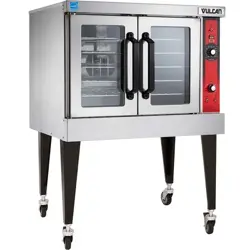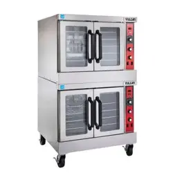
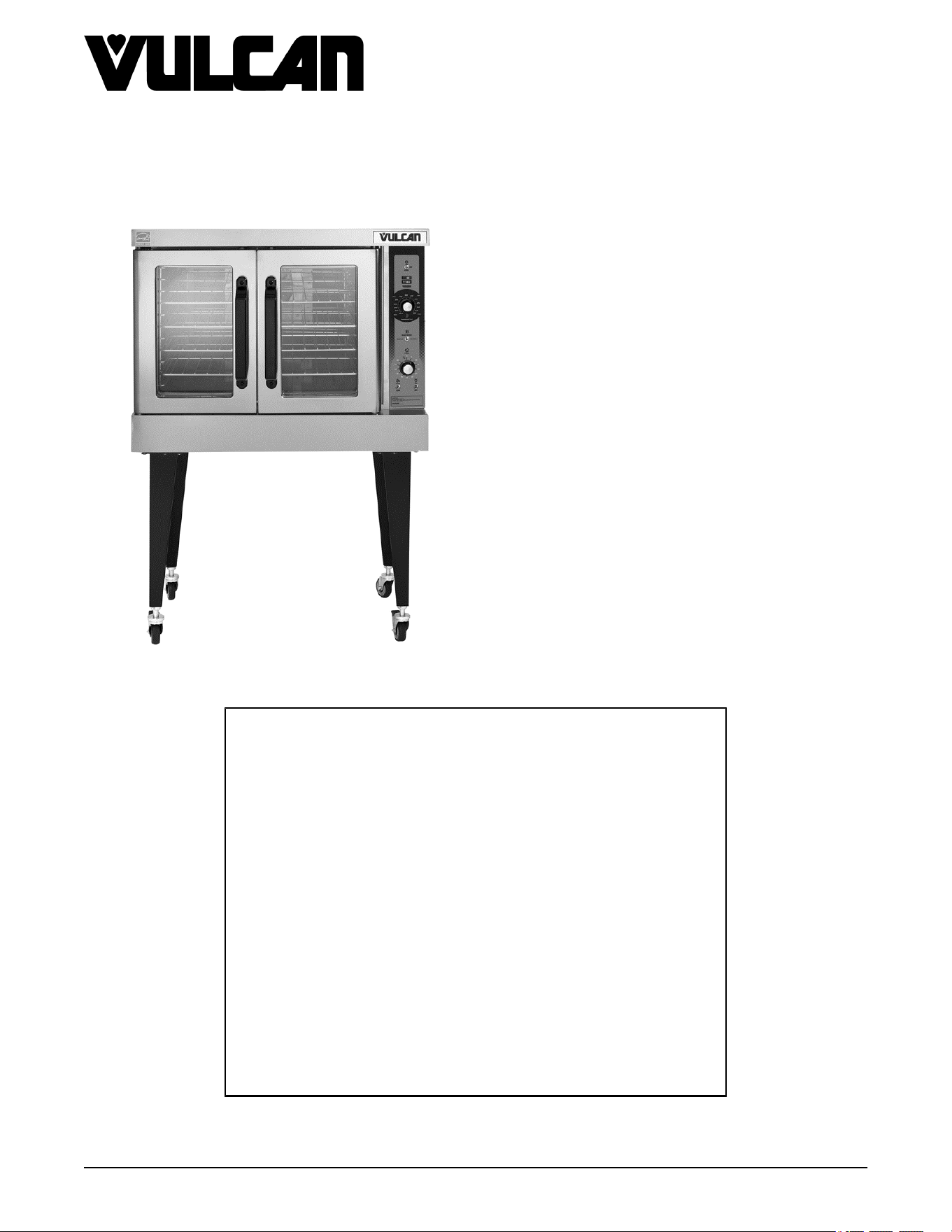
SG SERIES GAS CONVECTION
OVENS
MODELS SG4
SG6
STACKED
MODELS
SG44
SG66
- NOTICE -
This Manual is prepared for the use of trained Vulcan Service
Technicians and should not be used by those not properly
qualified.
This manual is not intended to be all encompassing. If you have
not attended a Vulcan Service School for this product, you should
read, in its entirety, the repair procedure you wish to perform to
determine if you have the necessary tools, instruments and skills
required to perform the procedure. Procedures for which you do
not have the necessary tools, instruments and skills should be
performed by a trained Vulcan Service Technician.
The reproduction, transfer, sale or other use of this Manual,
without the express written consent of Vulcan, is prohibited.
This manual has been provided to you by ITW Food Equipment
Group LLC ("ITW FEG") without charge and remains the property
of ITW FEG, and by accepting this manual you agree that you will
return it to ITW FEG promptly upon its request for such return at
any time in the future.
SERVICE MANUAL
A product of Vulcan-Hart 3600 North Point Blvd Baltimore, MD 21222
F45525 Rev. B (1118)

TABLE OF CONTENTS
SERVICE UPDATES ....................................................................................... 4
SERVICE UPDATES - SG .............................................................................. 4
GENERAL .................................................................................................. 5
INTRODUCTION ....................................................................................... 5
INSTALLATION ........................................................................................ 5
OPERATION ........................................................................................... 5
CLEANING ............................................................................................. 5
LUBRICATION ......................................................................................... 5
SPECIFICATIONS ...................................................................................... 5
TOOLS ................................................................................................. 5
REMOVAL AND REPLACEMENT OF PARTS ............................................................... 6
COVERS AND PANELS ................................................................................ 6
TOP FRONT COVER ............................................................................... 6
BOTTOM FRONT COVER .......................................................................... 6
CONTROL PANEL ................................................................................. 6
RIGHT SIDE PANEL ................................................................................ 6
CONTROL PANEL COMPONENTS ..................................................................... 7
COMPONENT PANEL COMPONENTS ................................................................. 7
TEMPERATURE PROBE ............................................................................... 8
GAS BURNER ......................................................................................... 9
GAS ORIFICE .......................................................................................... 9
GAS SOLENOID VALVE .............................................................................. 10
IGNITION CONTROL MODULE ....................................................................... 11
SPARK IGNITER AND FLAME SENSE ................................................................ 12
BLOWER AND MOTOR ENDING AT PRODUCTION DATE OF 3/18/2018 .............................. 13
BLOWER AND MOTOR STARTING AT PRODUCTION DATE OF 3/19/2018 ........................... 15
OVEN DOORS AND BEARINGS (INDEPENDENT DOORS) ENDING AT
PRODUCTION DATE OF 1/21/2018 ............................................................... 16
OVEN DOORS (INDEPENDENT DOORS) STARTING AT PRODUCTION DATE OF 1/22/2018 ......... 17
ROLLER LATCH ASSEMBLY (INDEPENDENT DOORS) ............................................... 18
DOOR WINDOW ...................................................................................... 18
DOOR SWITCH ....................................................................................... 19
HIGH LIMIT THERMOSTAT ........................................................................... 19
INTERIOR LIGHTS .................................................................................... 20
COOLING FAN ........................................................................................ 20
INTERIOR LIGHTS (REAR MOUNTED, ROUND) ...................................................... 21
INTERIOR LIGHTS (SIDE MOUNTED, SQUARE) ...................................................... 21
DOOR ADJUSTMENT ................................................................................. 23
SERVICE PRODCEDURES AND ADJUSTMENTS ......................................................... 25
SOLID STATE TEMPERATURE CONTROL CALIBRATION ............................................ 25
SOLID STATE TEMPERATURE CONTROL TEST ..................................................... 26
TEMPERATURE PROBE TEST ....................................................................... 27
GAS VALVE PRESSURE CHECK ..................................................................... 27
VERIFICATION OF SPARK AT IGNITOR .............................................................. 28
DOOR SWITCH ADJUSTMENT ....................................................................... 29
BLOWER ADJUSTMENT .............................................................................. 29
DOOR ADJUSTMENT ................................................................................. 30
DOOR STRIKE ADJUSTMENT (INDEPENDENT DOORS) ............................................. 31
FLAME SENSE CURRENT TEST ...................................................................... 31
ELECTRICAL OPERATION ................................................................................ 34
COMPONENT LOCATION ............................................................................. 34
COMPONENT FUNCTION ............................................................................ 37
SEQUENCE OF OPERATION ......................................................................... 38
SG SERIES GAS CONVECTION OVENS
F45525 Rev. B (1118) Page 2 of 46

NORMAL CYCLE ................................................................................. 38
COOL DOWN CYCLE (SOLID STATE TEMPERATURE CONTROL) ................................ 40
SCHEMATICS ........................................................................................ 41
WIRING DIAGRAM .................................................................................... 42
TROUBLESHOOTING ..................................................................................... 44
ALL MODELS ......................................................................................... 44
IGNITION MODULE DIAGNOSTICS ................................................................... 45
SG SERIES GAS CONVECTION OVENS
© VULCAN 2018
Page 3 of 46 F45525 Rev. B (1118)
SERVICE UPDATES
SERVICE UPDATES - SG
October 2018
• FLAME SENSE CURRENT TEST
• OVEN DOORS (INDEPENDENT DOORS)
Starting at Production Date of 1/22/2018
• INTERIOR LIGHTS (Rear Mounted, Round)
• INTERIOR LIGHTS (Side Mounted, Square)
• DOOR ADJUSTMENT
• COMPONENT LOCATION
• SCHEMATICS
• WIRING DIAGRAM
• IGNITION MODULE DIAGNOSTICS
SG SERIES GAS CONVECTION OVENS - SERVICE UPDATES
F45525 Rev. B (1118) Page 4 of 46
GENERAL
INTRODUCTION
Procedures in this manual will apply to all models unless specified. Pictures and illustrations can be of any model
unless the picture or illustration needs to be model specific.
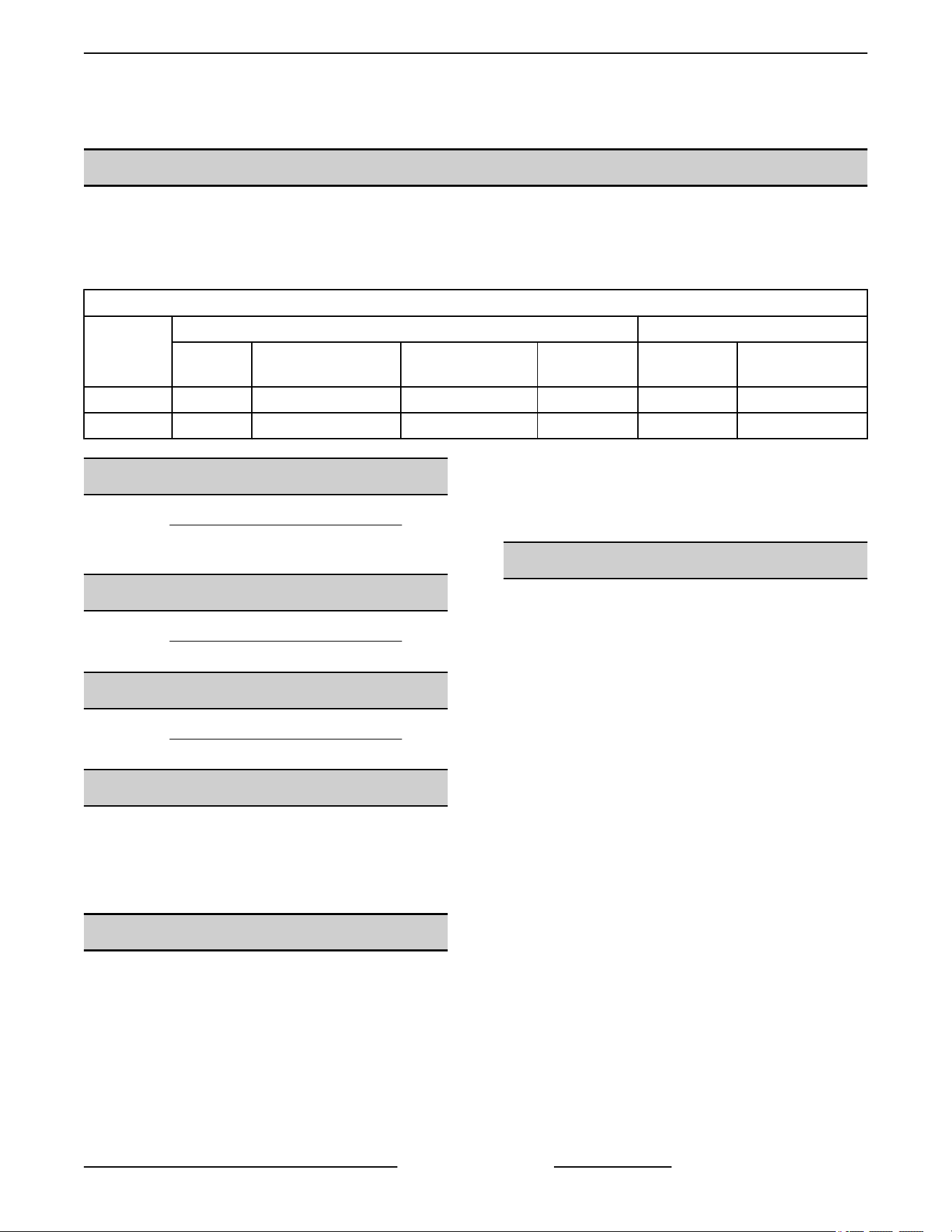
MODELS
MODEL
FEATURES OPTIONS
CAVITY
DEPTH
TEMPERTURE
CONTROL
DOORS (50/50)
COOK
TIMER
CASTERS
BLOWER
208/240/60/1
SG4 26.5" Solid State Independent 1-Hour Dial Optional Optional
SG6 30.5" Solid State Independent 1-Hour Dial Optional Optional
INSTALLATION
Refer to the Installation and Operation Manual for
detailed installation instructions on single or stacked
ovens.
OPERATION
Refer to the Installation and Operation Manual for
specific operating instructions.
CLEANING
Refer to the Installation and Operation Manual for
specific cleaning instructions.
LUBRICATION
• Cavity blower motor has sealed bearings and
requires no additional lubrication.
• Huskey™ TF-1000 grease or equivalent high
temperature Teflon grease.
SPECIFICATIONS
Electrical
Voltage - 120/60/1
Amps - 8.0 Amps
Input BTU Rating
Natural Gas - 60,000 BTU input at 5.0 in. W.C.
Propane Gas - 60,000 BTU input at 10.0 in. W.C.
Gas Line Pressures
Natural - Recommend (in. W.C.) 8.0, Min 6.0
Propane - Recommend (in. W.C.) 11.0, Min 11.0
Maximum 14.0 in. W.C. (Nat. or Prop.)
TOOLS
Standard
• Standard set of hand tools
• VOM with ability to measure micro amp current
VOM with minimum of NFPA-70E CAT III 600V,
UL/CSA/TUV listed. Sensitivity of at least 20,000
ohms per volt. Meter leads must also be rated at
CAT III 600V.
• Gear Puller to remove blower
Special
• Temperature tester (thermocouple type)
• Manometer
SG SERIES GAS CONVECTION OVENS - GENERAL
Page 5 of 46 F45525 Rev. B (1118)
REMOVAL AND REPLACEMENT OF PARTS
COVERS AND PANELS
Disconnect the electrical power to
the machine and follow lockout /
tagout procedures.
SHUT OFF THE GAS BEFORE SERVICING THE
UNIT.
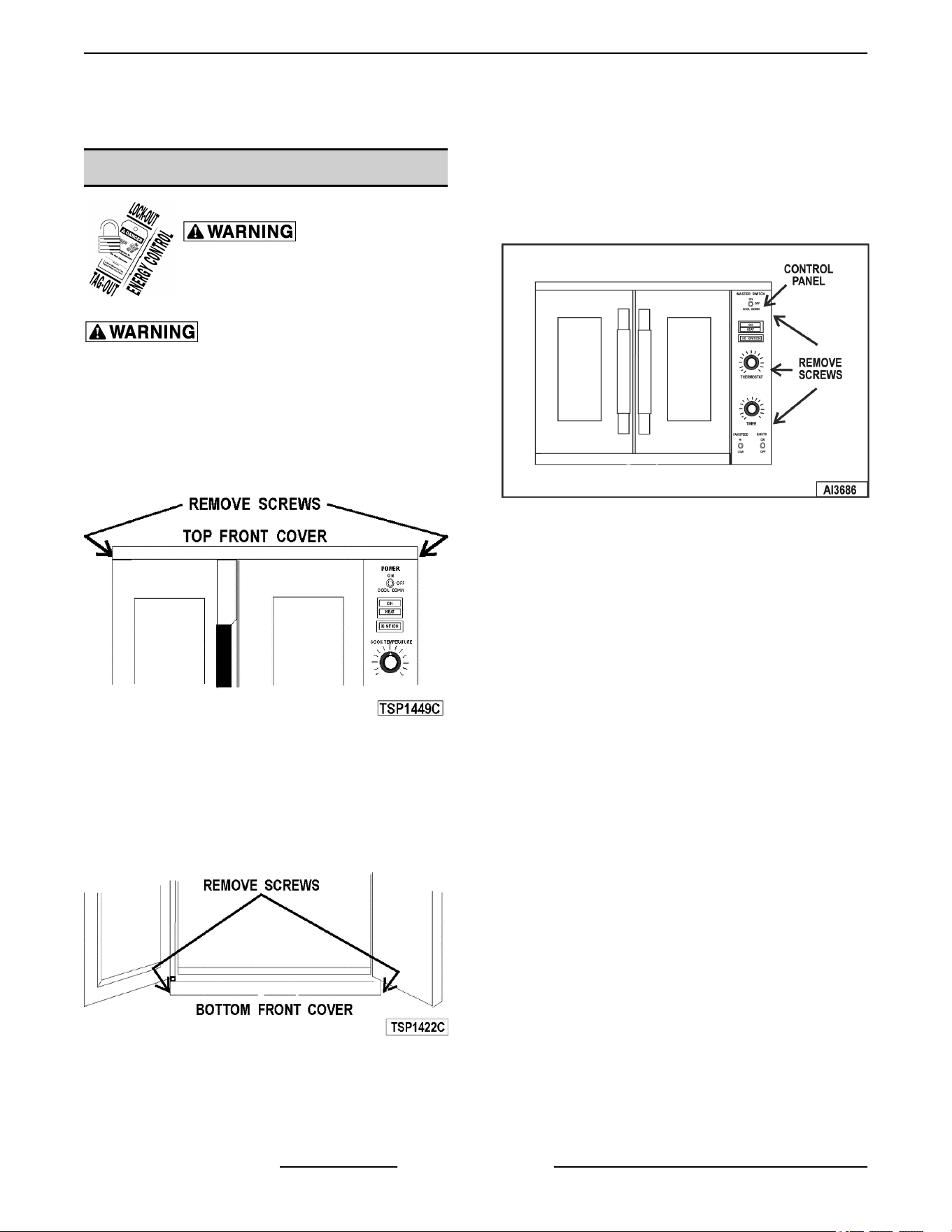
Top Front Cover
1. The top front cover is secured with four (4)
screws, two on each side of cover. Remove these
screws then remove the cover from the oven.
Fig. 1
2. Reverse the procedure to install.
Bottom Front Cover
1. The bottom front cover is secured with four (4)
screws, two on each side of cover. Remove these
screws then remove the cover from the oven.
Fig. 2
2. Reverse the procedure to install.
Control Panel
1. Remove three (3) screws on the right side which
secure the control panel then pull the panel away
from the oven.
Fig. 3
NOTE: If the oven has a mechanical (KX type)
thermostat, it must be removed from the control panel
first, before removing the control panel.
2. Disconnect the temperature probe leads from the
solid state temperature control.
3. Unplug the wire harness connector to the control
panel components.
4. Reverse the procedure to install.
Right Side Panel
1. Remove the screws which secure the right side
of the top front cover, bottom front cover and
control panel.
2. Remove the remaining six screws securing the
right side panel.
SG SERIES GAS CONVECTION OVENS - REMOVAL AND REPLACEMENT OF PARTS
F45525 Rev. B (1118) Page 6 of 46
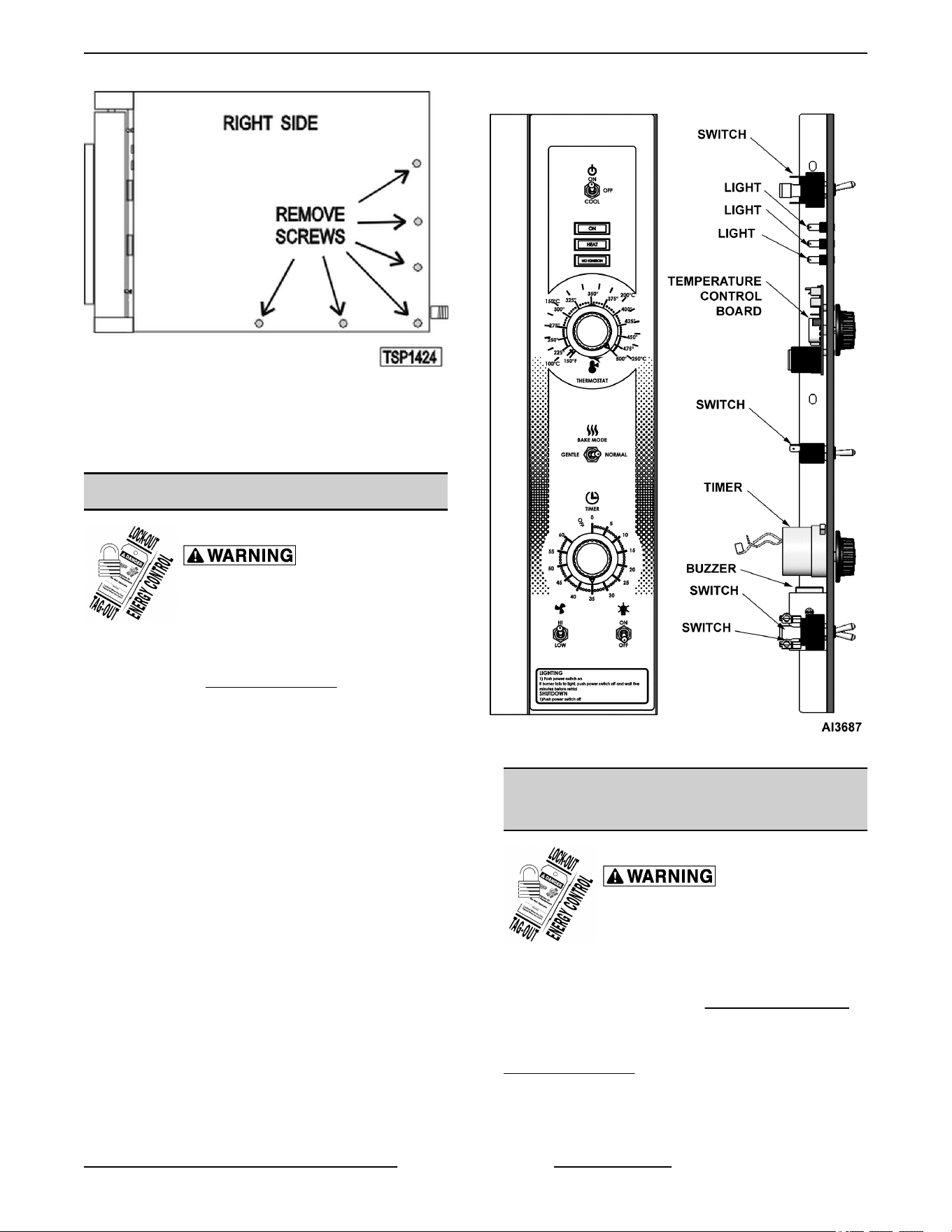
Fig. 4
3. Pull the right side panel out at the bottom then
down to remove.
4. Reverse the procedure to install.
CONTROL PANEL COMPONENTS
Disconnect the electrical power to
the machine and follow lockout /
tagout procedures.
Removable Components Procedure
1. Remove the CONTROL PANEL.
2. Remove the component being replaced.
3. Reverse the procedure to install the replacement
component, then check oven for proper
operation.
Fig. 5
COMPONENT PANEL
COMPONENTS
Disconnect the electrical power to
the machine and follow lockout /
tagout procedures.
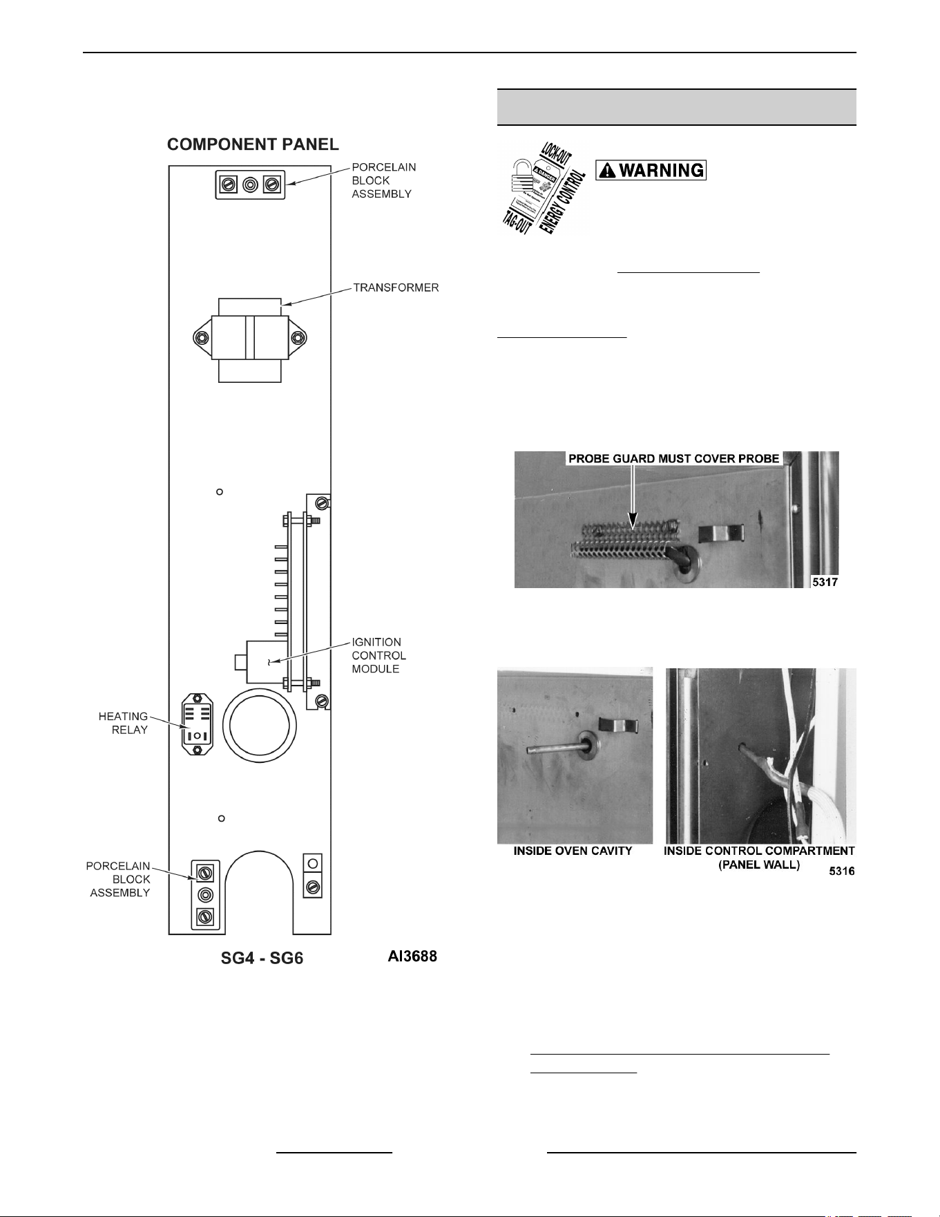
Removable Components Procedure
1. Remove the as outlined RIGHT SIDE PANEL.
NOTE: If right side panel is not accessible, this
component can be serviced by removing the
CONTROL PANEL.
2. Disconnect the wire leads to the component
being replaced.
3. Remove the component.
SG SERIES GAS CONVECTION OVENS - REMOVAL AND REPLACEMENT OF PARTS
Page 7 of 46 F45525 Rev. B (1118)
4. Reverse the procedure to install the replacement
component and check oven for proper operation.
Fig. 6
TEMPERATURE PROBE
Disconnect the electrical power to
the machine and follow lockout /
tagout procedures.
1. Remove the RIGHT SIDE PANEL.
NOTE: If right side panel is not accessible, this
component can be serviced by removing the
CONTROL PANEL.
2. Disconnect the probe leads from the solid state
temperature control.
3. Remove the racks and right rack support.
4. Remove the probe guard.
Fig. 7
5. Remove probe by pushing it through the oven
wall and into the control panel area.
Fig. 8
NOTE: The hole in the oven cavity wall does not line
up straight with the oven cavity outer shell, therefore
the probe must be removed at an angle.
6. Reverse the procedure to install the replacement
probe.
7. Adjust the temperature control as outlined under
SOLID STATE TEMPERATURE CONTROL
CALIBRATION .
SG SERIES GAS CONVECTION OVENS - REMOVAL AND REPLACEMENT OF PARTS
F45525 Rev. B (1118) Page 8 of 46
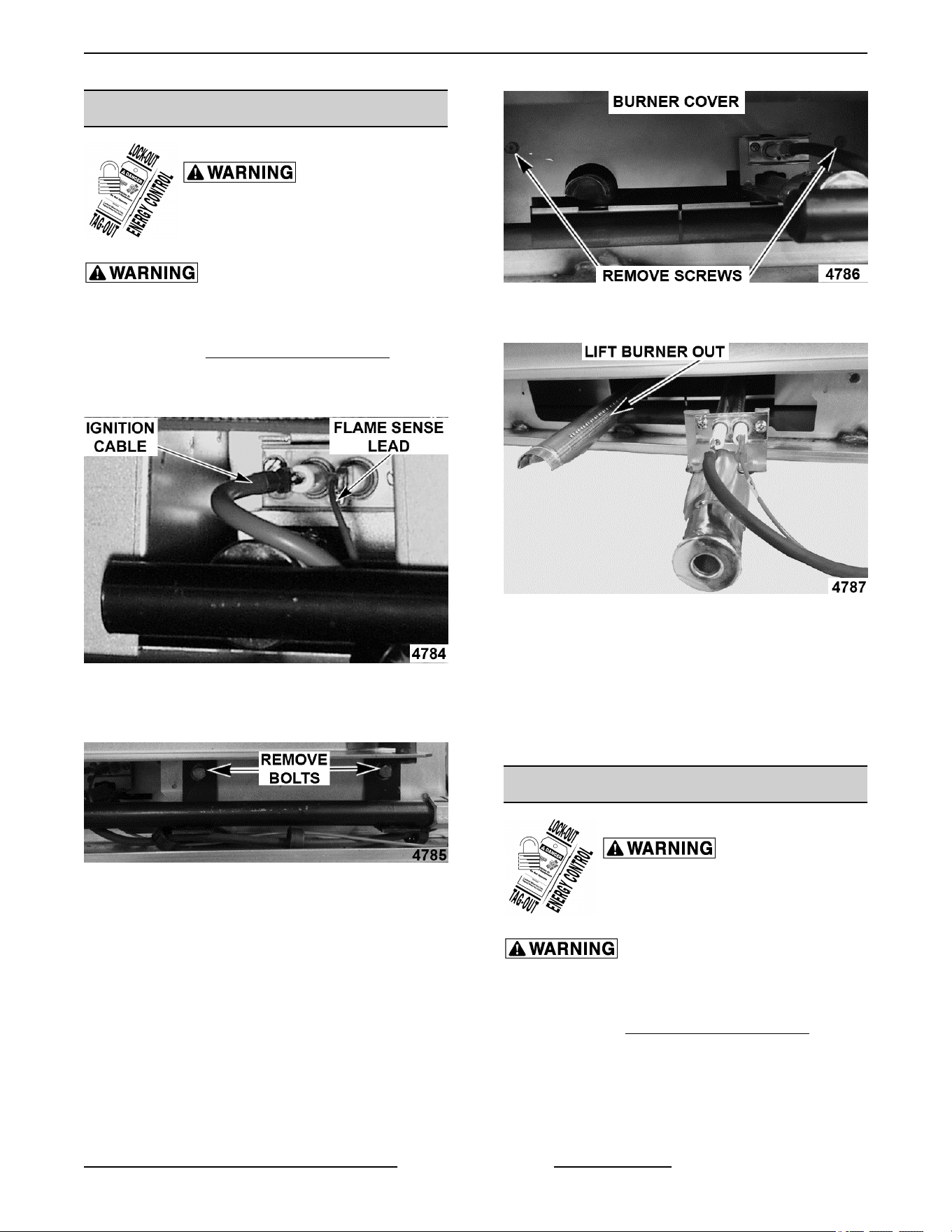
GAS BURNER
Disconnect the electrical power to
the machine and follow lockout /
tagout procedures.
SHUT OFF THE GAS BEFORE SERVICING THE
UNIT.
1. Remove the BOTTOM FRONT COVER.
2. Disconnect the ignition cable and the flame
sense lead wire.
Fig. 9
3. Disconnect the ignition cable and the flame
sense lead wire.
Fig. 10
4. Remove the screws securing the burner cover
then lift out.
Fig. 11
5. Grasp the burner and lift out.
Fig. 12
6. Reverse procedure to install the replacement
burner.
NOTE: Ensure that burner positioning bracket (U
shaped end) is inserted into slot at the rear of the
burner chamber.
7. Check for proper operation.
GAS ORIFICE
Disconnect the electrical power to
the machine and follow lockout /
tagout procedures.
SHUT OFF THE GAS BEFORE SERVICING THE
UNIT.
1. Remove the BOTTOM FRONT COVER.
2. Remove the bolts securing the gas manifold to
the oven and place the manifold to the side.
SG SERIES GAS CONVECTION OVENS - REMOVAL AND REPLACEMENT OF PARTS
Page 9 of 46 F45525 Rev. B (1118)
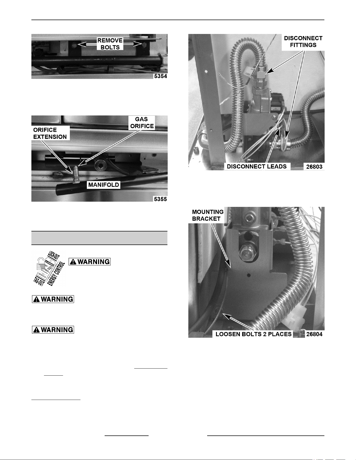
Fig. 13
3. Remove the gas orifice from the spud on the
manifold and replace with the correct orifice for
the given altitude.
Fig. 14
4. Reverse procedure to install and check for proper
operation.
GAS SOLENOID VALVE
Disconnect the electrical power to
the machine and follow lockout /
tagout procedures.
SHUT OFF THE GAS BEFORE SERVICING THE
UNIT.
All gas joints disturbed during servicing must be
checked for leaks. Check with a soap and water
solution (bubbles). Do not use an open flame.
1. Remove the Control Panel and the RIGHT SIDE
PANEL.
NOTE: If is right side panel not accessible, this
component can be serviced by removing the
CONTROL PANEL.
2. Disconnect the lead wires.
3. Disconnect the compression fittings to the valve.
Fig. 15
4. Loosen the bolts securing the valve and bracket
assembly then remove the screws securing the
valve to the bracket.
Fig. 16
5. Verify new gas valve is configured for the proper
gas type.
SG SERIES GAS CONVECTION OVENS - REMOVAL AND REPLACEMENT OF PARTS
F45525 Rev. B (1118) Page 10 of 46
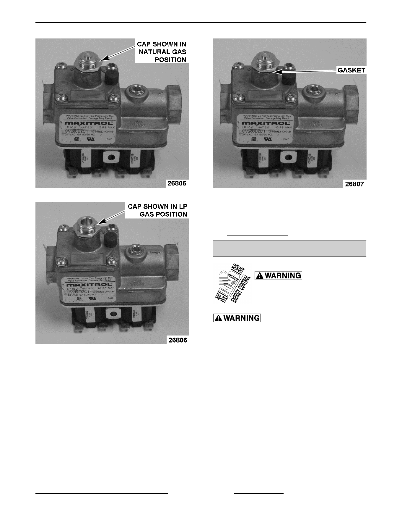
Fig. 17
Fig. 18
A. To change gas type unscrew and reverse
cap to show the proper gas type.
1) Make sure gasket is positioned
between cap and valve body.
Fig. 19
6. Reverse the procedure to install the replacement
gas valve.
7. Check pressure as outlined under GAS VALVE
PRESSURE CHECK.
IGNITION CONTROL MODULE
Disconnect the electrical power to
the machine and follow lockout /
tagout procedures.
SHUT OFF THE GAS BEFORE SERVICING THE
UNIT.
1. Remove the RIGHT SIDE PANEL.
NOTE: If right side panel is not accessible, this
component can be serviced by removing the
CONTROL PANEL.
2. Loosen the screws securing the mounting
bracket to the component panel and remove the
bracket.
SG SERIES GAS CONVECTION OVENS - REMOVAL AND REPLACEMENT OF PARTS
Page 11 of 46 F45525 Rev. B (1118)
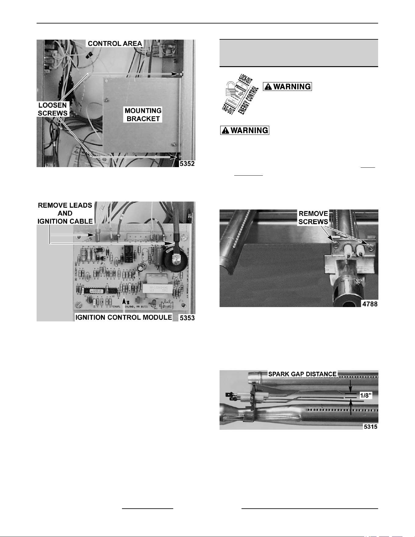
Fig. 20
3. Disconnect the lead wires and igniter cable from
the ignition module board.
Fig. 21
4. Remove the ignition module board from the
mounting bracket.
5. Reverse the procedure to install the replacement
ignition module board.
SPARK IGNITER AND FLAME
SENSE
Disconnect the electrical power to
the machine and follow lockout /
tagout procedures.
SHUT OFF THE GAS BEFORE SERVICING THE
UNIT.
1. Remove the gas burner as outlined under GAS
BURNER.
2. Remove the screws securing the ignitor and
flame sense to burner then remove the
assembly.
Fig. 22
3. Reverse the procedure to install the assembly
and check for proper operation.
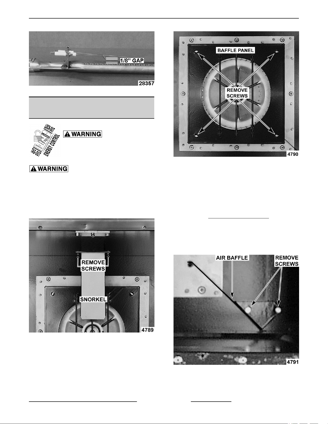
NOTE: Check to ensure the spark gap distance is
approximately 1/8". If the gap appears to be excessive
or poor sparking is occurring then adjust.
PREVIOUS PRODUCTION SHOWN
SG SERIES GAS CONVECTION OVENS - REMOVAL AND REPLACEMENT OF PARTS
F45525 Rev. B (1118) Page 12 of 46
CURRENT PRODUCTION SHOWN
BLOWER AND MOTOR Ending at
Production Date of 3/18/2018
Disconnect the electrical power to
the machine and follow lockout /
tagout procedures.
SHUT OFF THE GAS BEFORE SERVICING THE
UNIT.
1. Take out the racks and rack supports.
2. Remove screws securing the “snorkel” and
remove the snorkel.
Fig. 25
3. Remove screws securing baffle panel and
remove the panel.
Fig. 26
4. If replacing:
A. Blower Only - Loosen set screws on blower
hub and using a bearing puller, remove
blower from motor shaft.
1) Reverse procedure to install and adjust
blower position as outlined under
BLOWER ADJUSTMENT.
B. Motor - perform step 4A and continue
procedure.
5. Remove the screws securing the air baffle to the
rear wall at the lower right hand corner.
Fig. 27
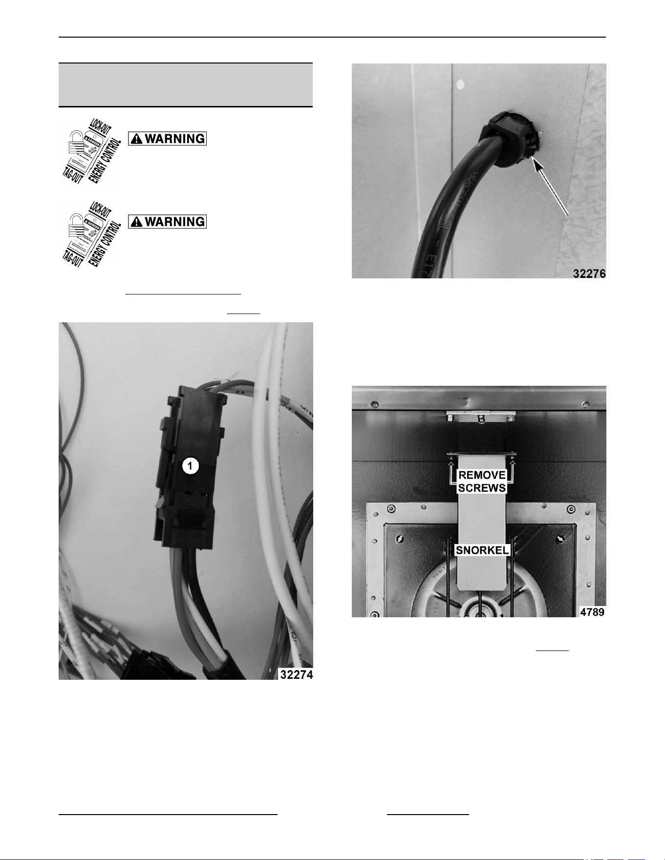
6. Remove the nuts that secure the motor mounting
plate to the rear wall.
SG SERIES GAS CONVECTION OVENS - REMOVAL AND REPLACEMENT OF PARTS
Page 13 of 46 F45525 Rev. B (1118)
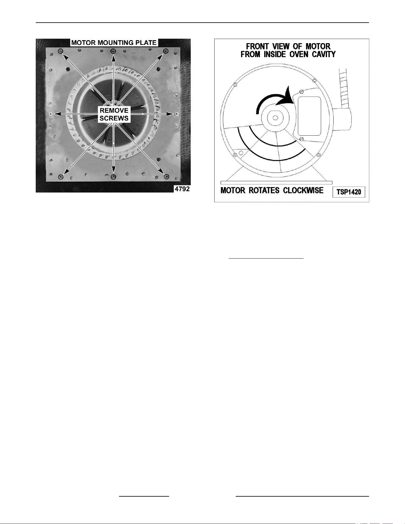
Fig. 28
7. Place a piece of cardboard on the bottom of the
oven cavity to protect its surface from any
damage during motor assembly removal.
8. Pull the motor assembly into the oven cavity and
place it on the cardboard.
9. Remove the junction box cover from the motor,
disconnect lead wires and remove the conduit.
10. Remove motor mounting bolts and flat washers
then lift the motor from the mounting plate.
11. Position the replacement motor on the motor
mounting plate and install mounting bolts and
washers. Hand tighten mounting bolts only.
12. Reconnect lead wires at the motor, replace
conduit and junction box cover.
NOTE: Check data plate on motor for wiring
schematic. The motor must rotate clockwise when
viewed from the shaft end.
Fig. 29
13. Slide blower onto motor shaft until hub is flush
with end of shaft then tighten set screws.
14. Adjust motor position until blower is parallel to
motor mounting plate as outlined under
BLOWER ADJUSTMENT.
15. Position motor mounting plate on the rear wall
and secure with nuts and washers.
16. Replace the baffle panel and “snorkel”.
17. Replace the air baffle on the rear wall at the lower
right hand corner.
18. Remove cardboard from the bottom of the oven
cavity.
19. Install rack guides and racks.
20. Check oven for proper operation.
SG SERIES GAS CONVECTION OVENS - REMOVAL AND REPLACEMENT OF PARTS
F45525 Rev. B (1118) Page 14 of 46
BLOWER AND MOTOR Starting at
Production Date of 3/19/2018
Disconnect the electrical power to
the machine and follow lockout /
tagout procedures.
Shut off the gas before servicing the
unit and follow lockout / tagout
procedures.
1. Remove RIGHT SIDE PANEL(S).
2. Disconnect motor harness (1, Fig. 30).
Fig. 30
3. Pinch cord grip together to remove from rear
panel.
Fig. 31
4. Push motor wiring harness/cord out hole in rear
panel.
5. Remove racks.
6. Remove screws securing "snorkel" and remove
snorkel.
Fig. 32
7. Remove blower baffle screws (2, Fig. 33) if
applicable.
SG SERIES GAS CONVECTION OVENS - REMOVAL AND REPLACEMENT OF PARTS
Page 15 of 46 F45525 Rev. B (1118)
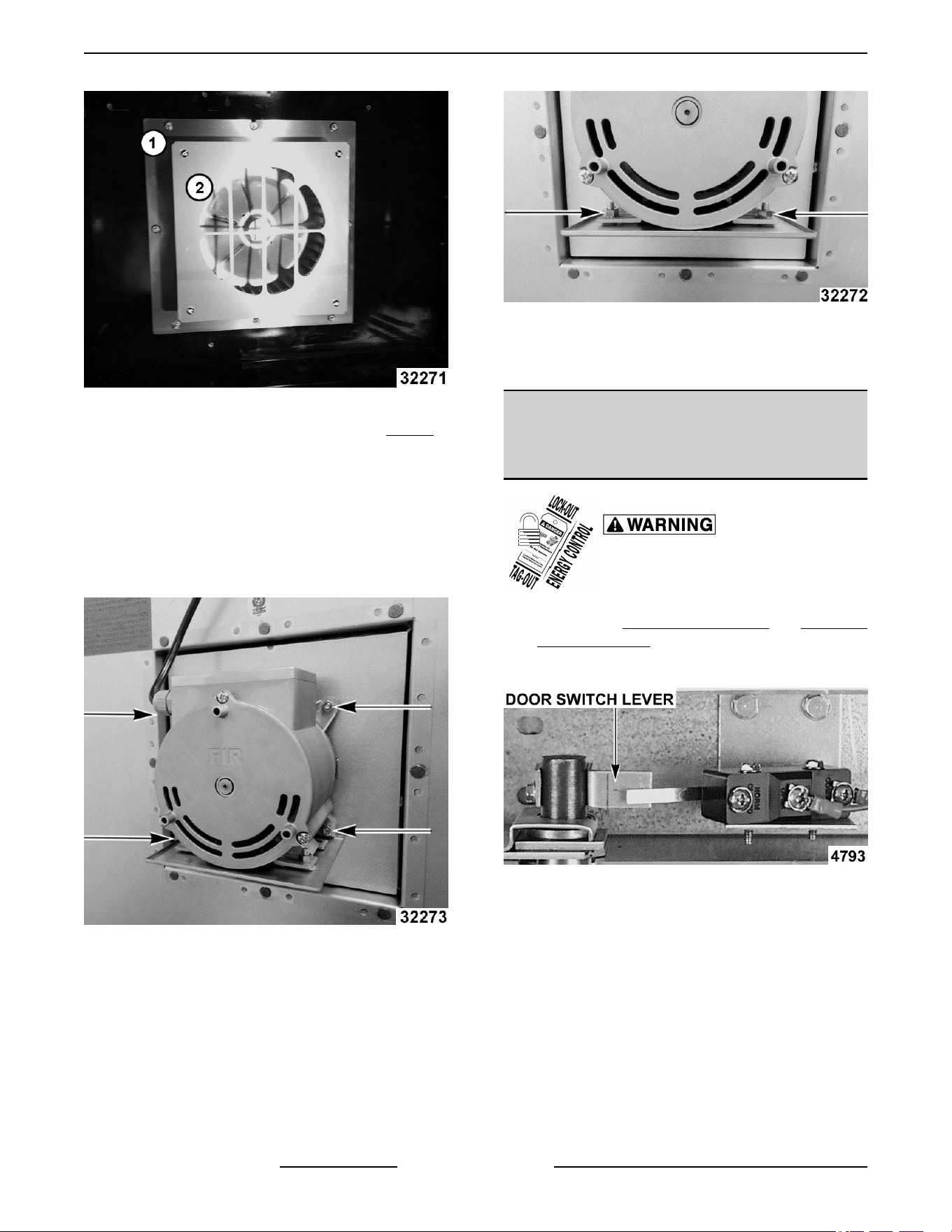
Fig. 33
8. Remove motor mounting plate nuts (1, Fig. 33).
9. Place a piece of cardboard on bottom of oven
cavity to protect its surface from any damage
during motor assembly removal.
10. Pull motor assembly into oven cavity and place
on cardboard.
11. Remove motor mounting bolts and washers and
lift motor off mounting plate.
Fig. 34
NOTE: Motor graphics are shown with motor
installed.
12. Remove drip pan from motor and install onto
replacement motor.
Fig. 35
13. Reverse procedure to install.
14. Verify operation.
OVEN DOORS AND BEARINGS
(INDEPENDENT DOORS) Ending at
Production Date of 1/21/2018
Disconnect the electrical power to
the machine and follow lockout /
tagout procedures.
1. Remove the TOP FRONT COVER and BOTTOM
FRONT COVER.
2. Remove the door switch lever.
Fig. 36
3. Remove the lower door seal strip to expose the
mounting screws of the door assembly.
4. Remove the two (2) lower sill bolts by the lower
door shaft and the four (4) counter-sunk screws
from the lower sill.
SG SERIES GAS CONVECTION OVENS - REMOVAL AND REPLACEMENT OF PARTS
F45525 Rev. B (1118) Page 16 of 46
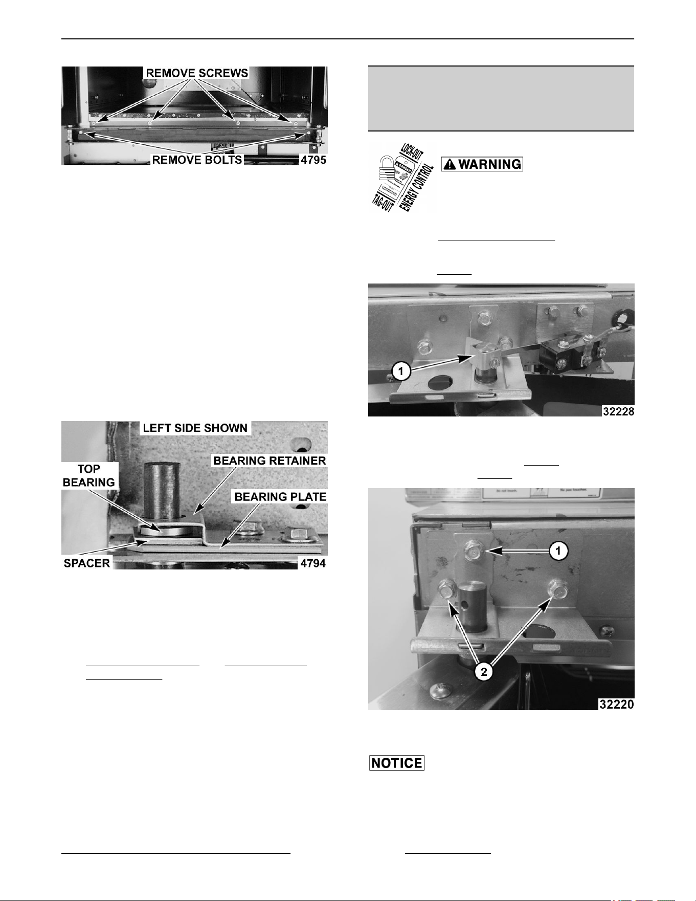
Fig. 37
NOTE: The door assembly is heavy and will drop
down once the last screw is removed. If removing door
assembly with-out assistance, the ignition cable,
flame sense lead and gas manifold should also be
removed to avoid damage to these components.
5. Tilt the top of the door slightly forward and lift the
door up until the bottom of the door shaft clears
the opening in the sill.
6. Lay the door flat to prevent damage.
7. The top and bottom bearings are now accessible
for inspection and/or replacement if needed.
A. If bearings are OK, proceed to step 8.
B. If replacing the top bearing, remove the top
bearing retainer and top bearing.
Fig. 38
C. If replacing the bottom bearing, remove it
from the door shaft or the lower sill opening.
8. Reverse procedure to install door assembly and
check for proper adjustment as outlined under
DOOR ADJUSTMENT and DOOR SWITCH
ADJUSTMENT.
OVEN DOORS (INDEPENDENT
DOORS) Starting at Production
Date of 1/22/2018
Disconnect the electrical power to
the machine and follow lockout /
tagout procedures.
1. Remove TOP FRONT COVERS.
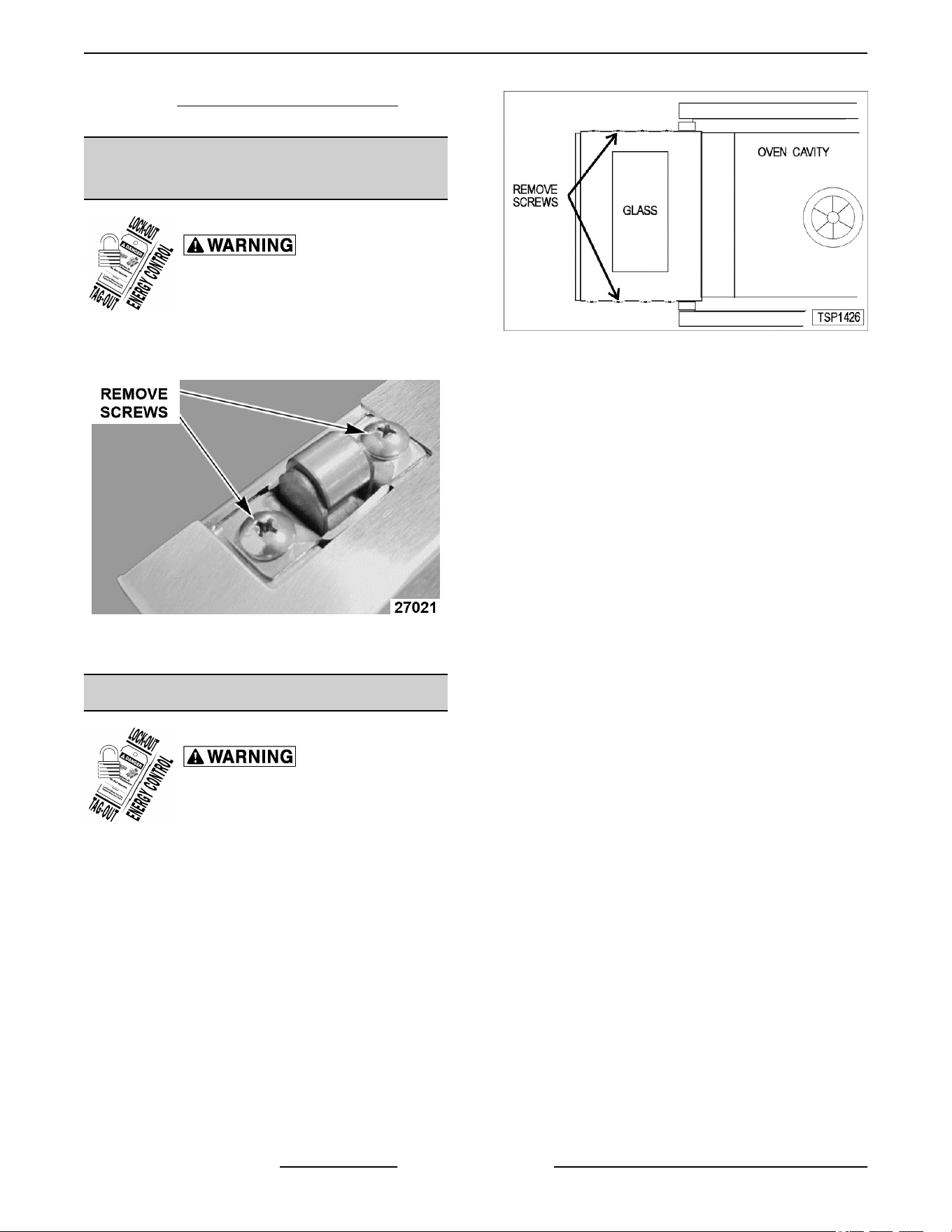
2. If servicing right side door, remove door switch
lever (1, Fig. 39).
Fig. 39
3. While supporting door, remove hex bolts holding
upper bearing retainer (1, Fig. 40 ) and upper
shaft bracket (2, Fig. 40).
Fig. 40
4. Lift door off lower shaft bracket.
Lay door on flat protective surface to service.
5. Reverse procedure to install.
SG SERIES GAS CONVECTION OVENS - REMOVAL AND REPLACEMENT OF PARTS
Page 17 of 46 F45525 Rev. B (1118)
6. Perform DOOR SWITCH ADJUSTMENT if
servicing right side door.
ROLLER LATCH ASSEMBLY
(INDEPENDENT DOORS)
Disconnect the electrical power to
the machine and follow lockout /
tagout procedures.
1. Remove the screws that attach roller latch
assembly to door.
Fig. 41
2. Reverse procedure to install.
DOOR WINDOW
Disconnect the electrical power to
the machine and follow lockout /
tagout procedures.
1. Remove the screws at the top and bottom of
door.
Fig. 42
2. Independent doors:
A. Remove the door handle then remove the
outer door panel.
B. Lift out the inner door panel and window
assembly.
NOTE: Left door only - remove door seal from the
inside edge of the door.
3. Simultaneous doors:
A. If replacing window on the left door, remove
the handle from the front of the door then
remove door seal from the inside edge of the
door.
1) Lift out the inner door panel and
window assembly.
2) If replacing window on the right door,
remove the screws along the inside
edge (if applicable) of the door then
remove the inner door panel and
window assembly.
4. Remove the screws securing the window “tabs”
to the door bracket and lift the window assembly
out from the door frame.
SG SERIES GAS CONVECTION OVENS - REMOVAL AND REPLACEMENT OF PARTS
F45525 Rev. B (1118) Page 18 of 46
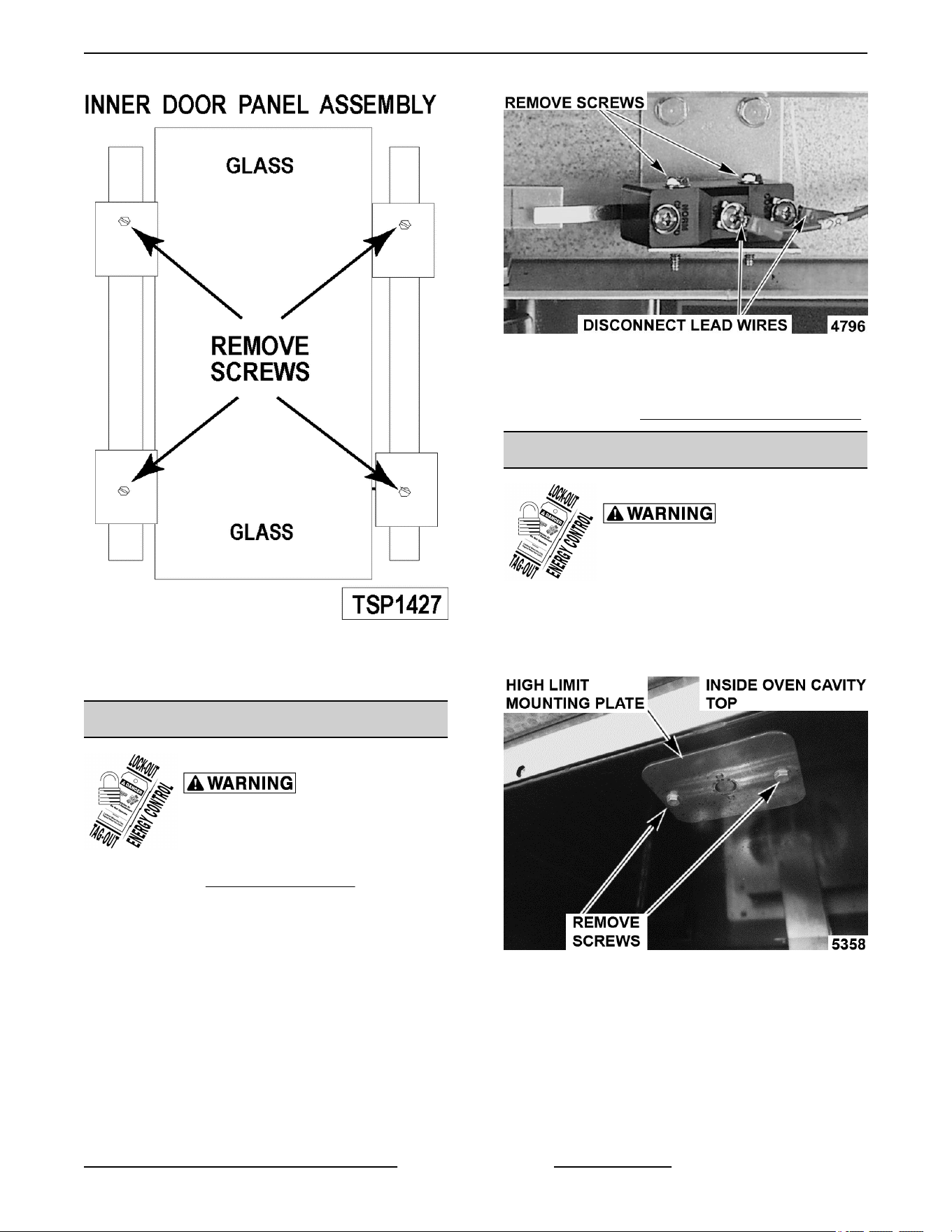
Fig. 43
5. Reverse procedure to install the replacement
window.
DOOR SWITCH
Disconnect the electrical power to
the machine and follow lockout /
tagout procedures.
1. Remove the TOP FRONT COVER.
2. Disconnect the lead wires to the door switch.
3. Remove the switch.
Fig. 44
4. Reverse procedure to install the replacement
switch and check for proper adjustment as
outlined under DOOR SWITCH ADJUSTMENT.
HIGH LIMIT THERMOSTAT
Disconnect the electrical power to
the machine and follow lockout /
tagout procedures.
1. Take out racks from the oven.
2. Remove the high limit thermostat cover/mounting
plate from inside the oven cavity at the top.
Fig. 45
3. Disconnect lead wires from high limit thermostat
then remove high limit thermostat from cover/
mounting plate.
SG SERIES GAS CONVECTION OVENS - REMOVAL AND REPLACEMENT OF PARTS
Page 19 of 46 F45525 Rev. B (1118)
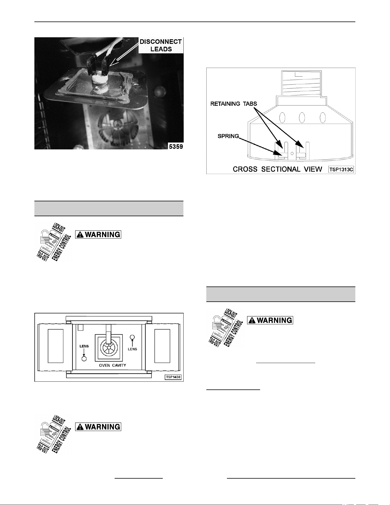
Fig. 46
NOTE: Remove the old RTV from the cover and
mating surfaces inside the oven cavity and apply new
RTV before installing.
4. Reverse procedure to install.
INTERIOR LIGHTS
Disconnect the electrical power to
the machine and follow lockout /
tagout procedures.
Lamp
1. Remove the racks.
2. Unscrew the glass lens for the light being
replaced then unscrew the bulb.
Fig. 47
3. Replace bulb then reverse the procedure to
install.
Disconnect the electrical power to
the machine and follow lockout /
tagout procedures.
Lamp Assembly
1. Remove the lens and bulb.
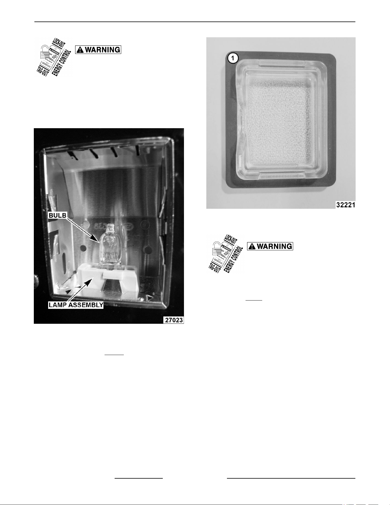
2. Remove the springs from the retaining tabs (2
places) on the socket.
Fig. 48
3. Depress the retaining tabs and pull the socket out
from the oven, far enough to disconnect the lead
wires.
4. Remove the socket from the oven.
5. Attach the lead wires to the replacement socket.
6. Insert the socket into the hole in the oven and
push until the socket is held in place by the
retaining tabs.
7. Install the light bulb and lens.
8. Check for proper operation.
COOLING FAN
Disconnect the electrical power to
the machine and follow lockout /
tagout procedures.
1. Remove the RIGHT SIDE PANEL.
NOTE: If right side panel is not accessible, this
component can be serviced by removing the
CONTROL PANEL.
2. Disconnect the lead wires to the fan motor by
removing wire nuts.
3. Remove the screws securing the air deflector to
the fan then loosen the tab screw holding the fan
to the component panel. Rotate the tab so that
the fan will clear and remove the fan.
SG SERIES GAS CONVECTION OVENS - REMOVAL AND REPLACEMENT OF PARTS
F45525 Rev. B (1118) Page 20 of 46
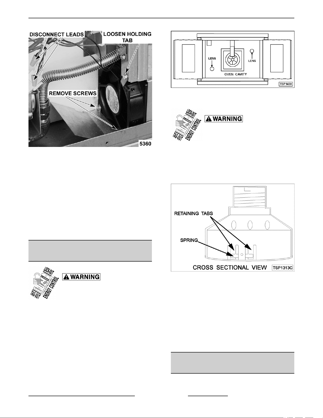
Fig. 49
4. Reverse the procedure to install the replacement
fan and check for proper operation.
NOTE: The fan must be installed so air is pulled from
the rear of the oven and blown into the control area.
The arrow on the fan body indicates “air flow” direction
and should be pointing toward the controls.
NOTE: Ensure fan is seated “squarely” against the air
tube and the oven bottom.
NOTE: The air deflector should be angled upwards
at approximately 30 degrees to properly direct the air
flow.
INTERIOR LIGHTS (Rear Mounted,
Round)
Disconnect the electrical power to
the machine and follow lockout /
tagout procedures.
Lamp
1. Remove racks.
2. Unscrew glass lens for the light being replaced
then unscrew bulb.
NOTE: Use a cloth when handling bulb so you do not
leave fingerprints on bulb.
Fig. 50
3. Replace bulb then reverse procedure to install.
Disconnect the electrical power to
the machine and follow lockout /
tagout procedures.
Lamp Assembly
1. Remove lens and bulb.
2. Remove springs from retaining tabs (2 places) on
the socket.
Fig. 51
3. Depress retaining tabs and pull socket out from
the oven, far enough to disconnect lead wires.
4. Remove socket from the oven.
5. Attach lead wires to the replacement socket.
6. Insert socket into the hole in oven and push until
socket is held in place by retaining tabs.
7. Install light bulb and lens.
8. Check for proper operation.
INTERIOR LIGHTS (Side Mounted,
Square)
Bulb Replacement
SG SERIES GAS CONVECTION OVENS - REMOVAL AND REPLACEMENT OF PARTS
Page 21 of 46 F45525 Rev. B (1118)
Disconnect the electrical power to
the machine and follow lockout /
tagout procedures.
1. Remove racks and right-side hand rack guide.
2. Pull lamp cover off.
3. Grasp lamp using a clean cloth and remove from
lamp assembly.
Fig. 52
4. Reverse procedure to install new bulb.
NOTE: Verify gasket (1, Fig. 53) is flat on lamp cover
and not damaged.
Fig. 53
Lamp Assembly Replacement
Disconnect the electrical power to
the machine and follow lockout /
tagout procedures.
1. Remove racks.
2. Remove BULB if reusing.
3. Lift right side rack guide off oven cavity.
4. Pull lamp cover off from the top or bottom.
5. Insert narrow blade screwdriver into tab and
bend out to release. Repeat with second tab.
SG SERIES GAS CONVECTION OVENS - REMOVAL AND REPLACEMENT OF PARTS
F45525 Rev. B (1118) Page 22 of 46
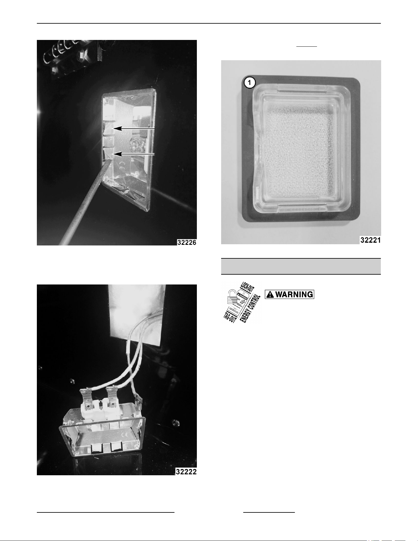
Fig. 54
6. Pull lamp housing out of oven cavity.
7. Disconnect wires.
Fig. 55
8. Reverse procedure to install.
NOTE: Verify gasket (1, Fig. 56) is flat on lamp cover
and not damaged.
Fig. 56
DOOR ADJUSTMENT
Disconnect the electrical power to
the machine and follow lockout /
tagout procedures.
1. Check the doors to make sure they have a .125
(1/8") gap between them and that the vertical
edge of the door is parallel to the vertical door
seal. If the doors are not positioned in this
manner, adjust the doors as described.
SG SERIES GAS CONVECTION OVENS - REMOVAL AND REPLACEMENT OF PARTS
Page 23 of 46 F45525 Rev. B (1118)
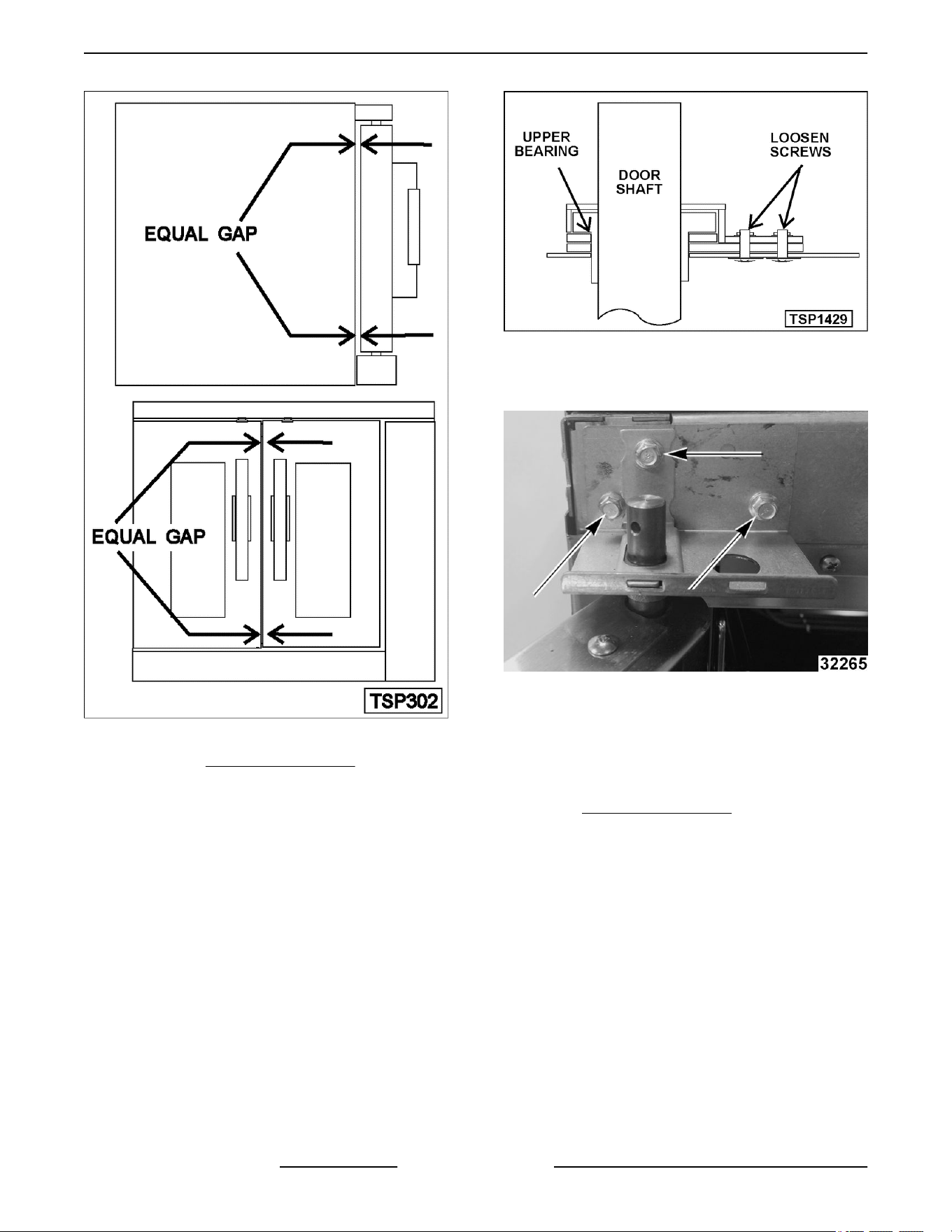
Fig. 57
2. Remove the TOP FRONT COVER.
3. Loosen the screws/bolts that secure the upper
door brackets just enough to allow door
movement.
Figure Shown below (Left Side) is ending at
Production Date of 1/21/2018.
Fig. 58
Figure shown below (Left Side) is starting at
Production Date of 1/22/2018.
Fig. 59
4. Move the door until proper alignment is achieved
then tighten the screws/bolts on the upper door
bearing hardware.
5. Repeat and on the opposite door, if necessary.
6. Install TOP FRONT COVER.
SG SERIES GAS CONVECTION OVENS - REMOVAL AND REPLACEMENT OF PARTS
F45525 Rev. B (1118) Page 24 of 46
SERVICE PRODCEDURES AND ADJUSTMENTS
Certain procedures in this section require electrical test or measurements while power is
applied to the machine. Exercise extreme caution at all times and follow Arc Flash procedures.
If test points are not easily accessible, disconnect power and follow Lockout/Tagout
procedures, attach test equipment and reapply power to test.
SOLID STATE TEMPERATURE
CONTROL CALIBRATION
1. Place a thermocouple in the geometric center of
the oven cavity.
2. Set the ON-OFF-COOL DOWN switch to ON.
3. Set the NORMAL - GENTLE BAKE switch to
NORMAL.
4. Set the temperature control dial to 350°F.
5. Allow the oven temperature to stabilize (normally
3 cycles).
6. Record the temperature at which the Heat lamp
goes OFF and comes ON for at least two
complete heating cycles.
7. Calculate the differential by subtracting the
temperature indicated when the lamp goes out
from the temperature indicated when the lamp
comes on.
Differential = Heat lamp OFF - Heat lamp ON
Example: 360° (lamp off) - 340° (lamp on) =
20°
A. The differential calculated should be less
than 20°F.
1) If the differential is less than 20°F, the
temperature control circuit is
functioning properly.
a. Proceed to Step 8.
2) If the differential is more than 20°F:
a. Check the temperature probe as
outlined under TEMPERATURE
PROBE TEST .
b. If the probe is functioning properly
then temperature control is
malfunctioning.
a) Install a replacement
temperature control and
check calibration.
8. Calculate the average temperature by adding the
temperature indicated when the lamp goes out to
the temperature indicated when the lamp comes
on and dividing this answer by 2.
[Temp. (lamp off) + Temp. (lamp on)] ÷ 2 =
Average Temp. Example: (360° + 340°) ÷ 2 =
350°
A. If the average temperature is less than 10°F
from the dial setting, the thermostat is
properly calibrated.
B. If the average temperature is more than
10°F from the dial setting, the thermostat
calibration must be adjusted.
1) Loosen the temperature control knob
set screw and remove the knob from
the stem.
2) Access the adjustment potentiometer
located at the 3 o'clock position.
a. Turn clockwise to increase,
counterclockwise to decrease
temperature
b. Repeat the average temperature
calculation in Step 8.
NOTE: Allow the oven to cycle at least two times
between adjustments before performing the
calculation.
a) If the average temperature
still differs more than 10°F
from the dial setting, adjust
the thermostat calibration
until the average
temperature is within
tolerance.
C. If the above adjustment cannot be obtained,
replace the temperature control and check
calibration.
SG SERIES GAS CONVECTION OVENS - SERVICE PRODCEDURES AND ADJUSTMENTS
Page 25 of 46 F45525 Rev. B (1118)
SOLID STATE TEMPERATURE
CONTROL TEST
Certain procedures in this section
require electrical test or
measurements while power is
applied to the machine. Exercise
extreme caution at all times and
follow Arc Flash procedures. If test
points are not easily accessible,
disconnect power and follow
Lockout/Tagout procedures, attach
test equipment and reapply power to
test.
1. Remove the RIGHT SIDE PANEL.
NOTE: If right side panel is not accessible, this
component can be serviced by removing
CONTROL
PANEL.
2. Place a thermocouple in the geometric center of
the oven cavity.
NOTE: Oven temperature must be below 450°F.
NOTE: If oven is equipped with "Cook and Hold"
option, set to Cook (normal cooking) before
continuing.
3. Set the temperature control to the maximum
setting.
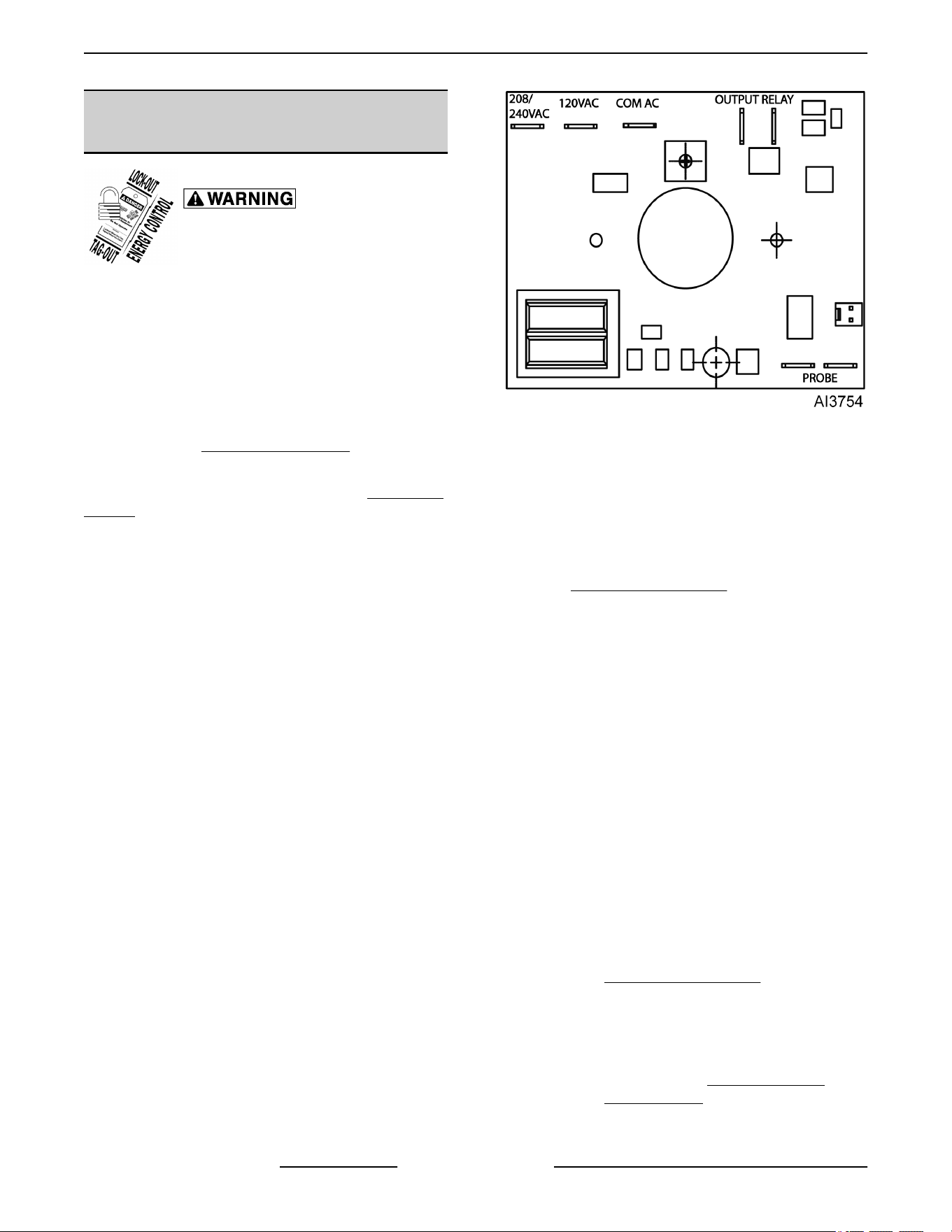
4. Check machine data plate for correct voltage to
oven. Refer to diagram below for proper terminal
locations and voltages before checking the
control. Use the correct terminals for the
corresponding voltage.
5. Turn the power switch to ON.
Fig. 60
6. Check for proper voltage across terminals COM
AC to 120VAC or COM AC to 208-240VAC for
power to the control.
A. If correct, proceed to step 7.
B. If incorrect, problem is not with the
temperature control. See
TROUBLESHOOTING.
7. Check relay voltages on the board:
A. For 120VAC controls - check across
OUTPUT RELAY terminal (left side) to
120VAC terminal for input to the internal
relay. Check across OUTPUT RELAY
terminal (right side) to 120 VAC for output
from the internal relay.
B. For 208-240VAC controls - check across
OUTPUT RELAY terminal (left side) to
208-240VAC terminal for input to the
internal relay. Check across OUTPUT
RELAY terminal (right side) to 208-240VAC
for output from the internal relay.
1) If input voltage to the internal relay is
correct, proceed to step 8. If input
voltage to the internal relay is not
present, problem is not with the
temperature control. See
TROUBLESHOOTING.
2) If output voltage from the internal relay
is correct proceed to step 8. If output
voltage from the internal relay is not
correct, check temperature probe as
outlined under TEMPERATURE
PROBE TEST.
8. Set the temperature control to the minimum
setting.
SG SERIES GAS CONVECTION OVENS - SERVICE PRODCEDURES AND ADJUSTMENTS
F45525 Rev. B (1118) Page 26 of 46
NOTE: Oven temperature must be above 300°F.
9. Check for zero (0) volts AC across terminals
OUTPUT RELAY terminal (right side) to 120VAC
or OUTPUT RELAY terminal (right side) to
208-240VAC for no output from the internal relay.
A. If correct, temperature control is functioning
properly.
B. If incorrect, check temperature probe as
outlined under TEMPERATURE PROBE
TEST.
1) If temperature probe is OK:
a. Turn the power switch OFF.
Disconnect the electrical power to
the machine and follow lockout /
tagout procedures.
b. Replace the temperature control
and check calibration as outlined
under
SOILD STATE
TEMPERATURE CONTROL
CALIBRATION.
TEMPERATURE PROBE TEST
Disconnect the electrical power to
the machine and follow lockout /
tagout procedures.
NOTE: The temperature probe used in conjunction
with the Solid State Temperature control is an RTD
(resistance temperature detector) of the Thermistor
type. As temperature increases the resistance value
decreases.
1. Remove the RIGHT SIDE PANEL.
NOTE: If right side panel is not accessible, this
component can be serviced by removing the
CONTROL PANEL.
2. Place a shielded thermocouple in the geometric
center of the oven cavity and determine the
temperature in the oven cavity.
3. Remove the probe lead wires from the solid state
temperature control.
4. Test the probe with an ohmmeter.
A. If the measured resistance values are inside
the given tolerance then the probe is
functioning properly.
B. If the measured resistance values are
outside the given tolerance then replace the
probe and retest.
1) Check oven for proper operation.
5. Reverse procedure to install.
TEMP (°F) OHMS* TEMP (°F) OHMS*
77 90,000 360 822
240 4,077 380 656
260 3,016 400 529
280 2,266 425 424
300 1,726 450 334
320 1,332 475 266
340 1,041
(*) Resistance in ohms ± 10%
GAS VALVE PRESSURE CHECK
Disconnect the electrical power to
the machine and follow lockout /
tagout procedures.
1. Turn gas supply off at manual shutoff valve.
2. Remove the RIGHT SIDE PANEL.
NOTE: If right side panel is not accessible, this
component can be serviced by removing the
CONTROL PANEL.
3. Remove the plug from the manifold pressure
port.
SG SERIES GAS CONVECTION OVENS - SERVICE PRODCEDURES AND ADJUSTMENTS
Page 27 of 46 F45525 Rev. B (1118)
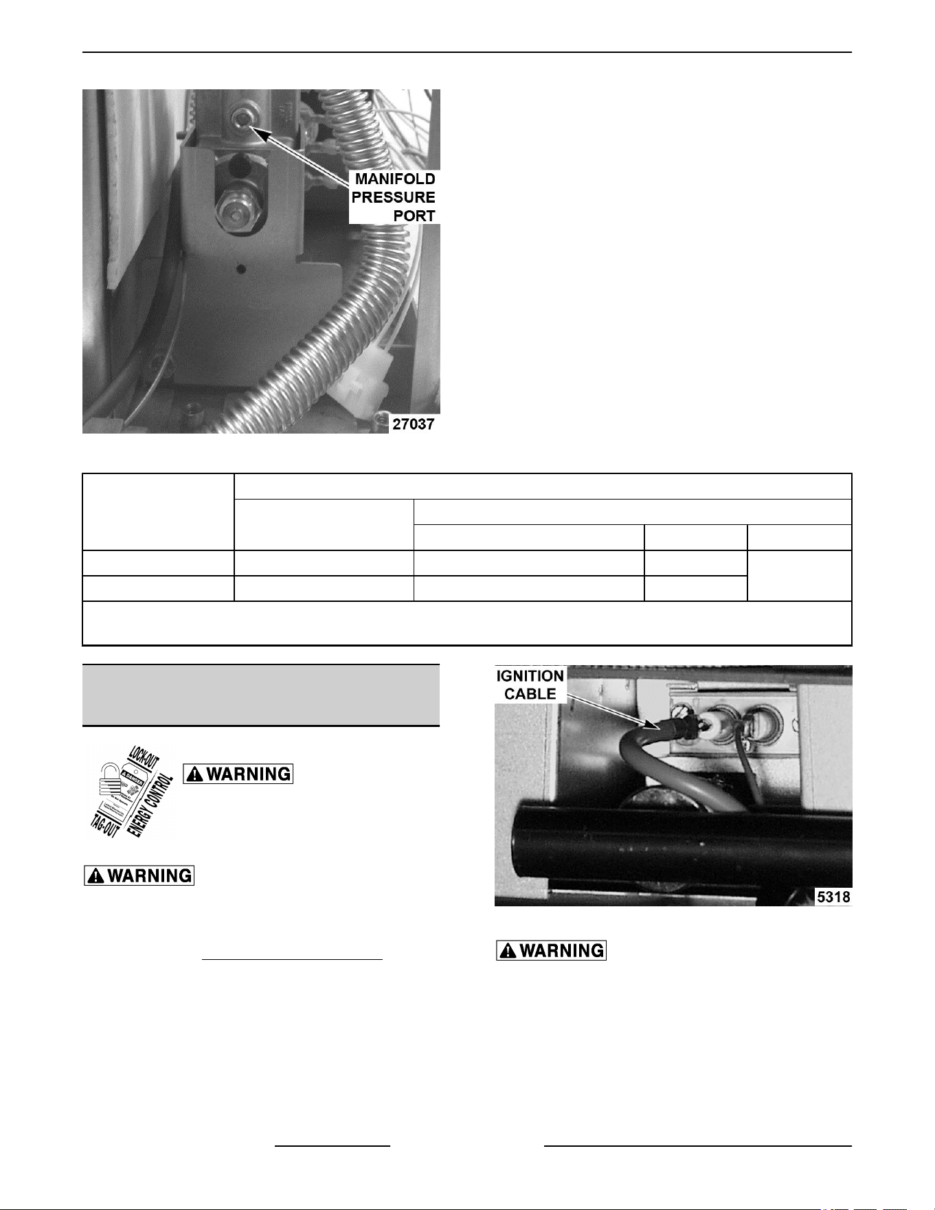
Fig. 61
4. Install hose barb adapter and attach manometer
tube.
5. Turn gas supply to the oven back on.
6. Plug the unit in and turn the power switch ON.
7. Set the temperature control to its highest setting
and allow burner to ignite.
NOTE: The burner must be lit during test.
NOTE: Accurate gas pressure readings can only be
made with the gas on and the burner lit.
GAS TYPE
PRESSURE READINGS (IN W.C.)
MANIFOLD
LINE
RECOMMENDED MIN MAX
Natural 5.0 8.0 6.0
14.0
Propane 10.0 11.0 11.0
NOTE: If the incoming line pressure to the valve is less than the minimum stated, then the manifold pressure will
not be maintained
VERIFICATION OF SPARK AT
IGNITOR
Disconnect the electrical power to
the machine and follow lockout /
tagout procedures.
SHUT OFF THE GAS BEFORE SERVICING THE
UNIT.
1. Remove the BOTTOM FRONT COVER.
2. Disconnect the high voltage "ignition cable" from
the spark ignitor.
Fig. 62
DO NOT HOLD THE WIRE WITH YOUR HANDS
FOR THIS TEST. THE MANUAL GAS VALVE MUST
BE CLOSED.
3. Clamp the ignition cable in a manner that will
position the end of the cable 3/16" from the oven
frame (bare metal surface).
SG SERIES GAS CONVECTION OVENS - SERVICE PRODCEDURES AND ADJUSTMENTS
F45525 Rev. B (1118) Page 28 of 46
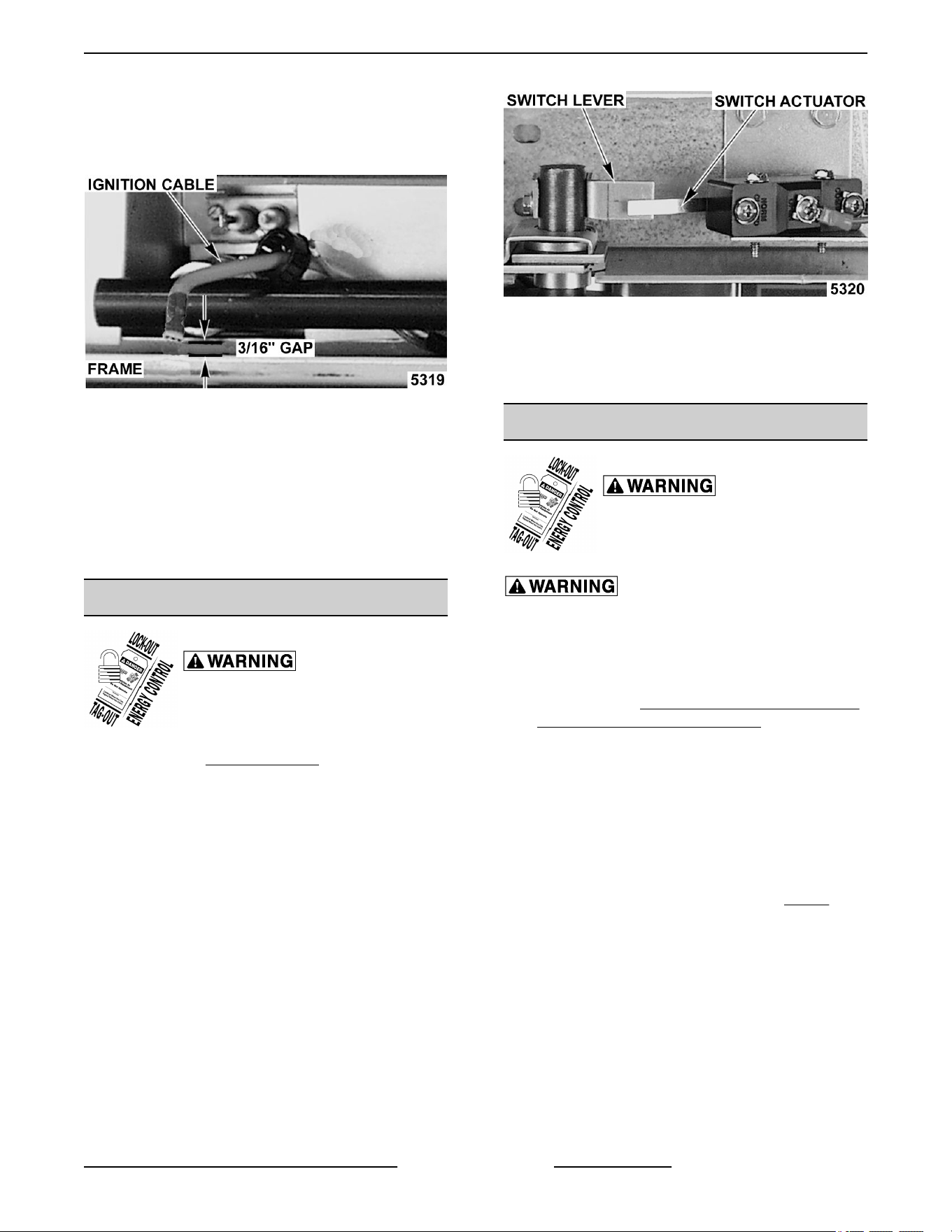
NOTE: It is critical that the cable be held 3/16" away
from the surface of the oven frame or sparking may
not occur even though the sparking circuit is
functioning properly.
Fig. 63
4. Plug the oven in and set the temperature control
to the maximum setting.
5. Turn the power switch ON.
6. Sparking should occur after a 4 second delay, for
a duration of 7 seconds then repeat twice after a
15 second purge time. Arching from the ignition
cable to the oven frame should be observed.
DOOR SWITCH ADJUSTMENT
Disconnect the electrical power to
the machine and follow lockout /
tagout procedures.
1. Remove the Top Front Cover.
2. Door operation:
A. Independent doors - The switch actuator
should be operated by the switch lever when
the right door is between 1" and 1 ½" from
being closed.
B. Simultaneous doors - The switch actuator
should be operated by the switch lever when
the right door is ½" from being closed.
3. If adjustment is necessary, bend the switch
actuator to obtain the proper setting.
Fig. 64
4. Install the top front cover.
5. Apply power to the oven and check for proper
operation.
BLOWER ADJUSTMENT
Disconnect the electrical power to
the machine and follow lockout /
tagout procedures.
SHUT OFF THE GAS BEFORE SERVICING THE
UNIT.
1. Remove the blower motor and mounting
assembly by following steps 1 through 8 as
outlined under BLOWER AND MOTOR Ending
at Production Date of 3/18/2018 .
2. Loosen the motor mounting bolts.
3. Adjust the motor position until the blower is
parallel to and 1/4 inch away from the motor
mounting plate. Check for squareness of the
blower to the motor mounting plate at the top,
bottom, left and right of the blower.
A. If the blower is square then tighten motor
mounting bolts and proceed to Step 4.
B. If the blower is not square continue
adjusting until proper spacing is achieved
then tighten motor mounting bolts.
NOTE: If necessary, place shims between motor and
frame.
SG SERIES GAS CONVECTION OVENS - SERVICE PRODCEDURES AND ADJUSTMENTS
Page 29 of 46 F45525 Rev. B (1118)
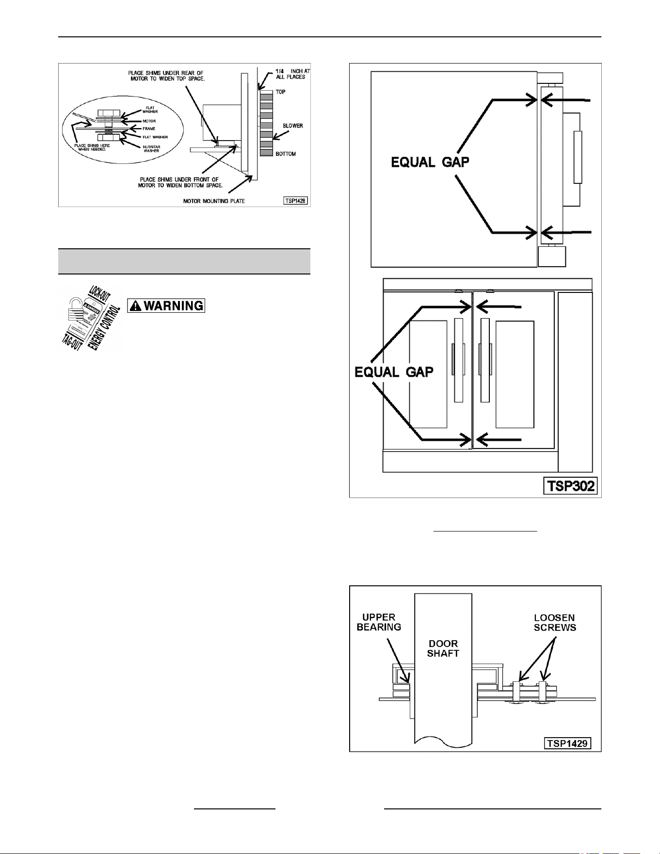
Fig. 65
4. Reverse the procedure to install.
DOOR ADJUSTMENT
Disconnect the electrical power to
the machine and follow lockout /
tagout procedures.
1. Check the doors to make sure they have an equal
gap between them and that the vertical edge of
the door is parallel to the vertical door seal. If the
doors are not positioned in this manner, adjust
the doors as described.
Fig. 66
2. Remove the TOP FRONT COVER.
3. Loosen the screws that secure the upper door
bearings and related hardware, just enough to
allow door movement.
Fig. 67
SG SERIES GAS CONVECTION OVENS - SERVICE PRODCEDURES AND ADJUSTMENTS
F45525 Rev. B (1118) Page 30 of 46

4. Move the door until proper alignment is achieved
then tighten the screws on the upper door
bearing hardware.
5. Repeat step 3 and 4 on the opposite door, if
necessary.
DOOR STRIKE ADJUSTMENT
(INDEPENDENT DOORS)
NOTE: For units with serial number starting with 48
made after 8/12/07 and serial number starting with 54
made after 8/26/07.
Disconnect the electrical power to
the machine and follow lockout /
tagout procedures.
1. Remove TOP FRONT COVER.
2. Open the doors and inspect door strike for proper
shape.
A. Replace if bent. Do not bend strike plate.
B. If adjustment is necessary, loosen
fasteners, close doors and insure contact
between door inner surface and upper
horizontal seal. Slide door strike plate until
contact with roller latch is made. Tighten
strike plate fasteners.
Fig. 68
3. Open and close the doors several times while
observing the roller latch and strike plate
operation.
A. Replace roller latch if malfunctioning as
outlined under ROLLER LATCH
ASSEMBLY (INDEPENDENT DOORS)
and adjust as outlined in this procedure.
4. Each oven door should open with a force of 8 to
25 pounds when pulled at the handle. The
adjustments must allow the doors to remain
closed during normal operation and allow
opening without exertion by the user.
FLAME SENSE CURRENT TEST
SG SERIES GAS CONVECTION OVENS - SERVICE PRODCEDURES AND ADJUSTMENTS
Page 31 of 46 F45525 Rev. B (1118)
Disconnect the electrical power to the machine and follow lockout / tagout procedures.
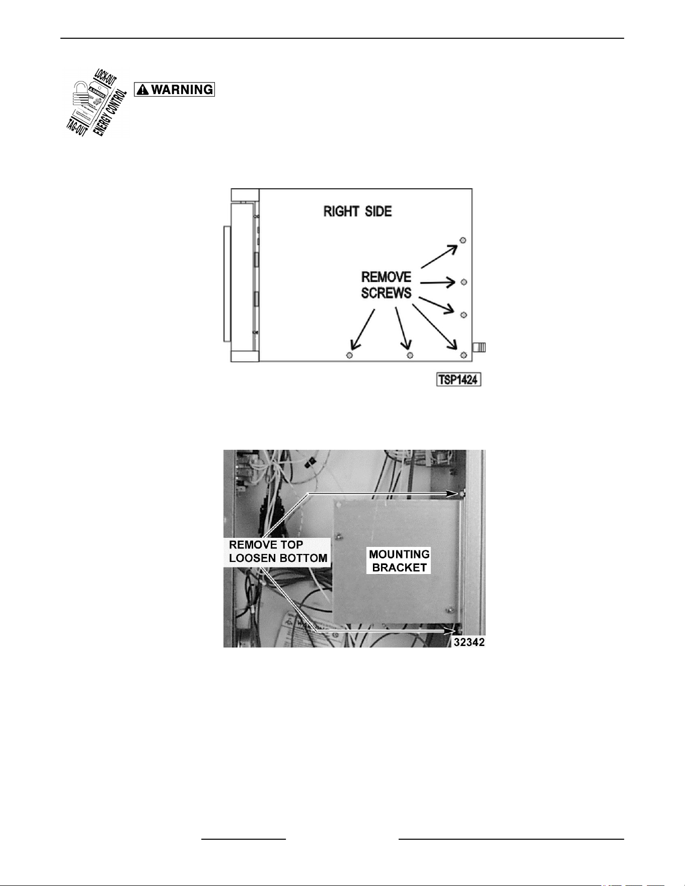
1. Remove screws securing right side of the top front cover, bottom front cover and control panel.
2. Remove right side panel mounting screws.
Fig. 69
3. Pull right side panel out from the bottom then down to remove.
4. Remove top screw and loosen bottom screw securing the ignition control module mounting bracket.
Fig. 70
5. Position bracket horizontally by pulling forward 90 degrees, with ignition module facing up for accessibility.
6. Re-apply power to unit.
7. Set VOM meter to read Micro Amps.
8. Place red (Positive) lead on FC+ and black (Negative) lead on FC- terminals on ignition module to test.
SG SERIES GAS CONVECTION OVENS - SERVICE PRODCEDURES AND ADJUSTMENTS
F45525 Rev. B (1118) Page 32 of 46
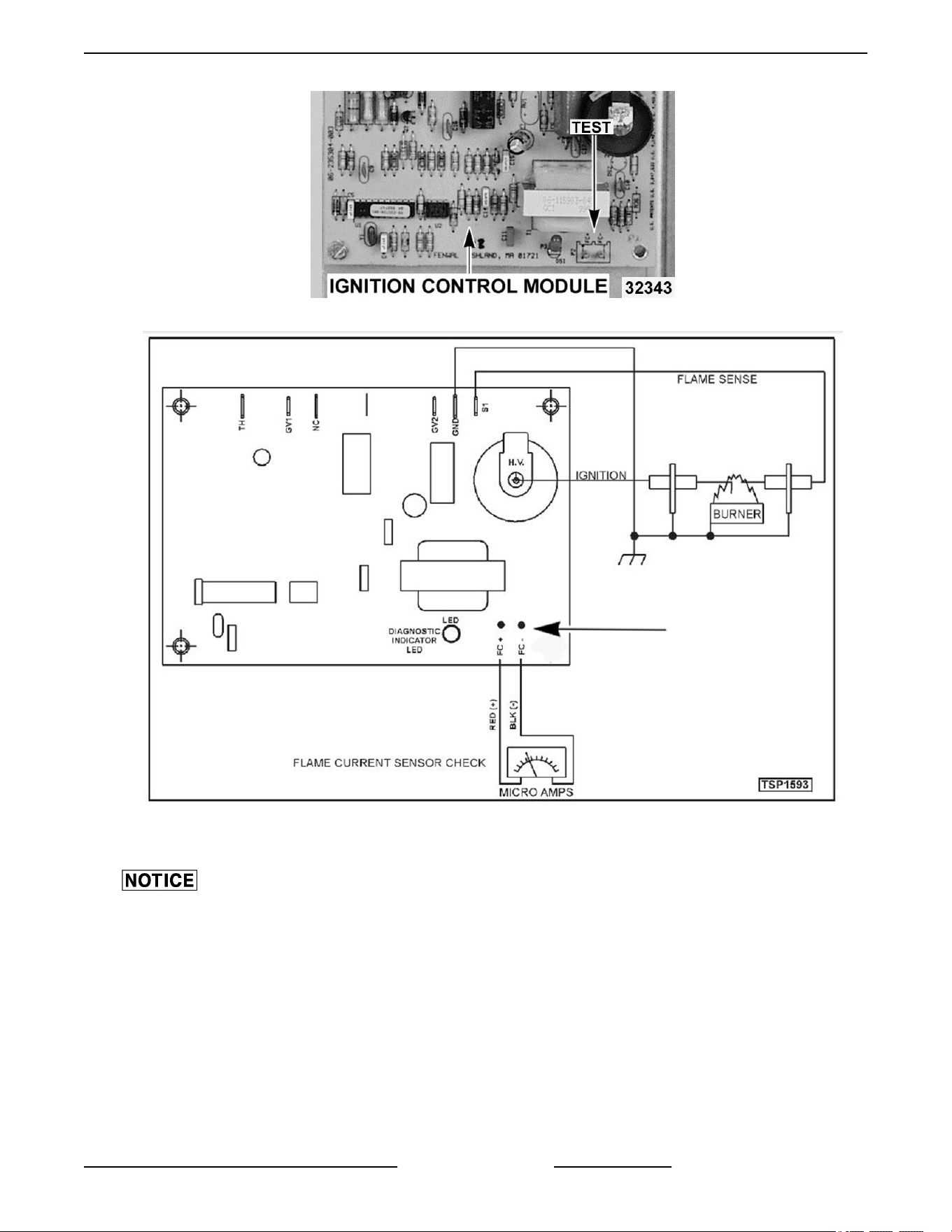
Fig. 71
Fig. 72
9. Set the oven to call for heat and measure the Micro Amps reading.
Micro Amp reading from the flame sensor should measure a minimum of 0.7 Micro Amps to maintain burner
ignition.
• If Micro amp reading is correct and the burner lights but does not maintain flame, replace ignition module.
• If Micro Amp reading is NOT correct, check wiring from flame sensor/igniter to the ignition module. If wiring
is OK, adjust, clean or replace flame sensor/igniter.
10. Install ignition control module mounting bracket and right panel.
11. Verify operation.
SG SERIES GAS CONVECTION OVENS - SERVICE PRODCEDURES AND ADJUSTMENTS
Page 33 of 46 F45525 Rev. B (1118)
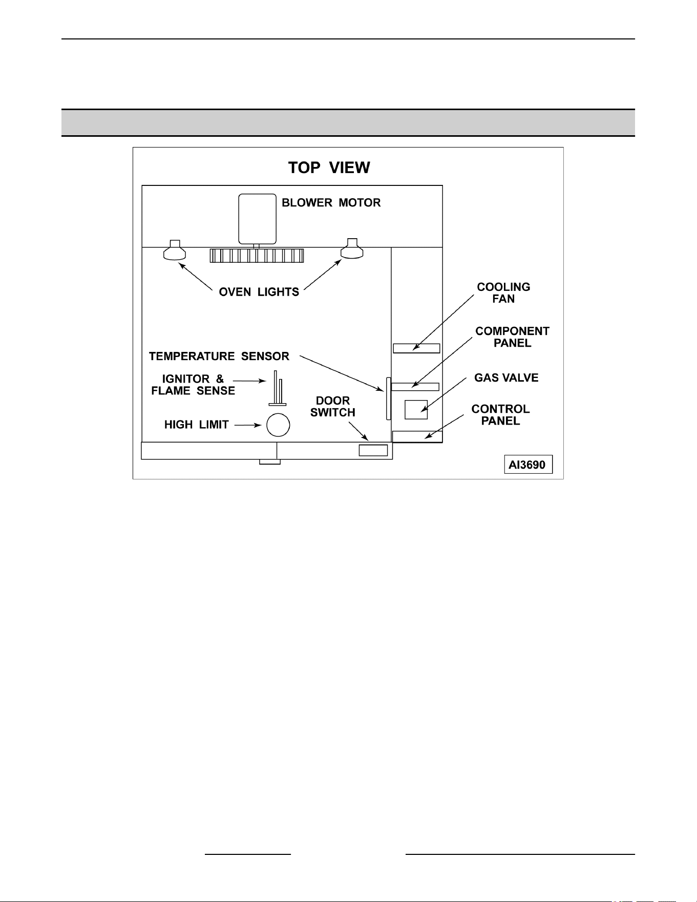
ELECTRICAL OPERATION
COMPONENT LOCATION
SHOWN IS UP TO MANUFACTURE DATE OF3/18/2018
SG SERIES GAS CONVECTION OVENS - ELECTRICAL OPERATION
F45525 Rev. B (1118) Page 34 of 46
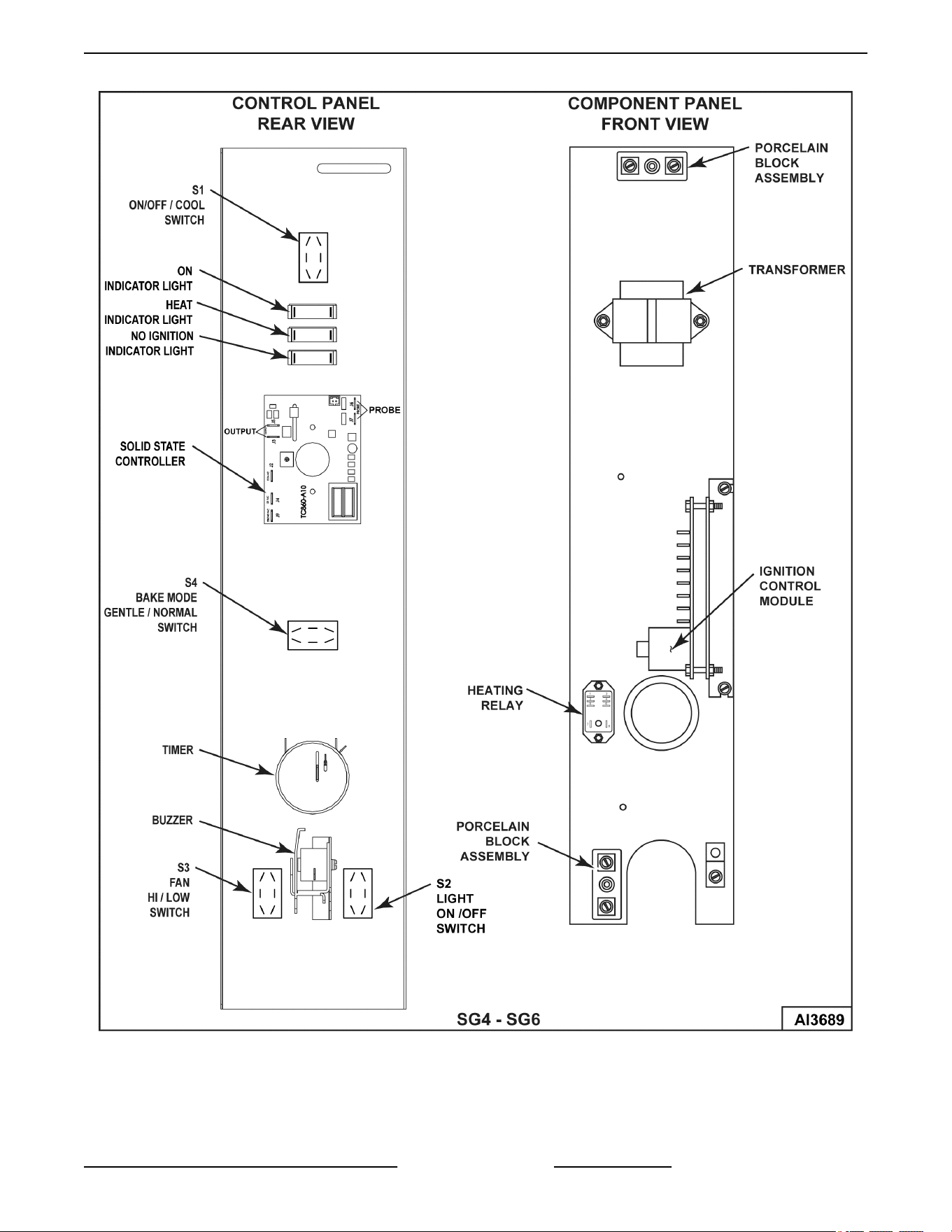
ENDING AT PRODUCTION DATE OF 3/18/2018
SG SERIES GAS CONVECTION OVENS - ELECTRICAL OPERATION
Page 35 of 46 F45525 Rev. B (1118)
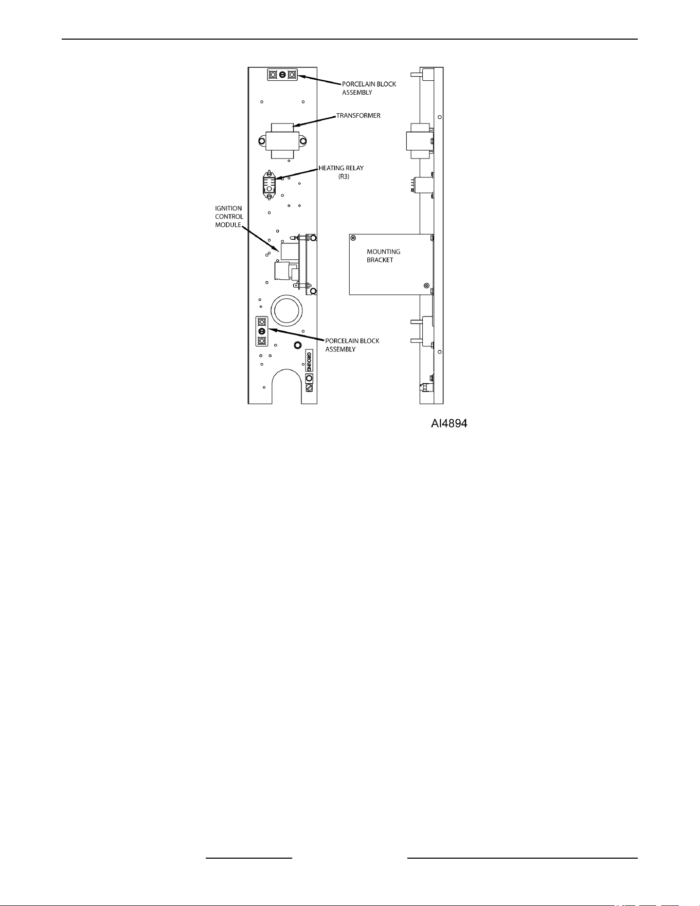
STARTING AT PRODUCTION DATE 3/18/2018 - 120V STANDARD
SG SERIES GAS CONVECTION OVENS - ELECTRICAL OPERATION
F45525 Rev. B (1118) Page 36 of 46
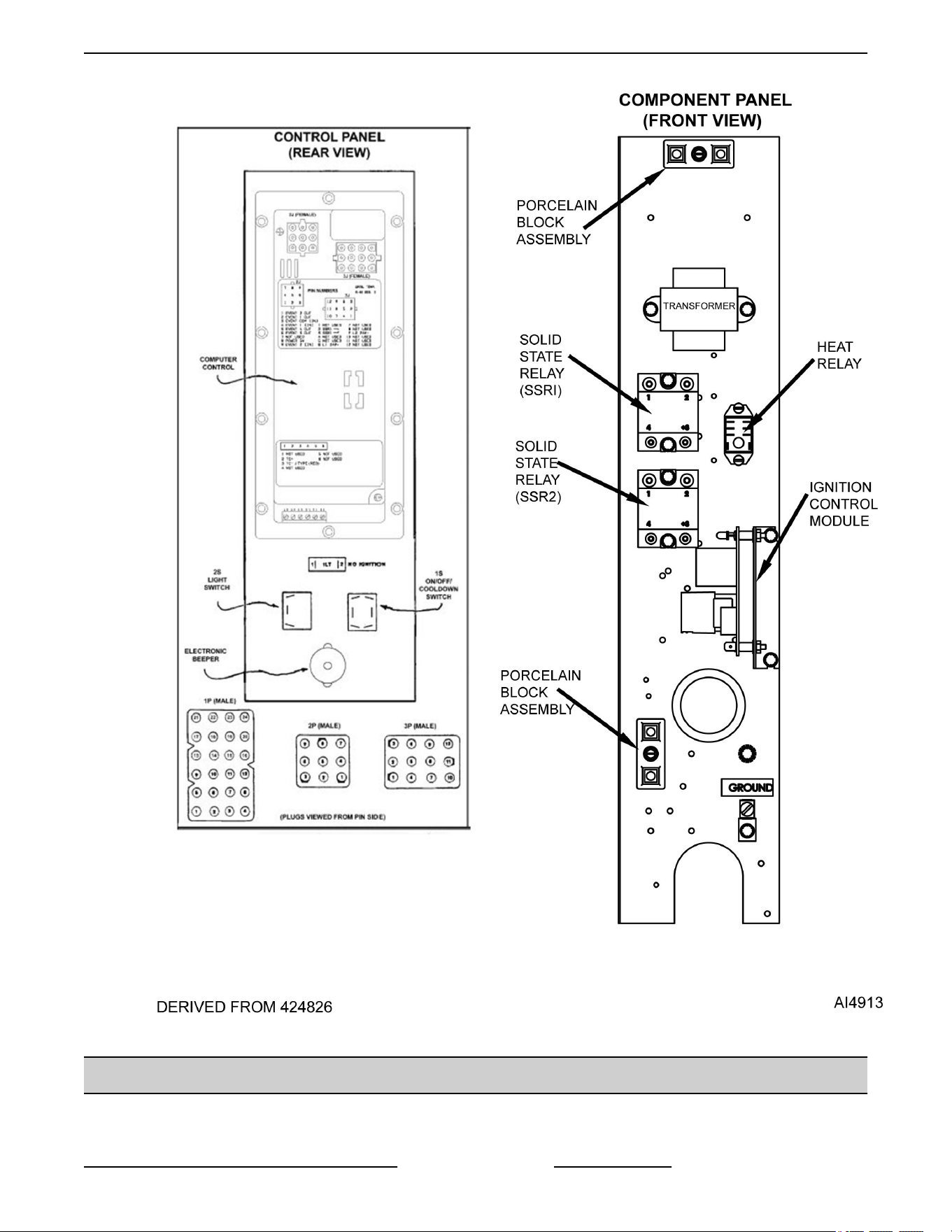
STARTING AT PRODUCTION DATE 3/18/2018 - 120V COMPUTER
COMPONENT FUNCTION
Power Switch (S1) .... Determines the mode of operation; ON, OFF, or COOL DOWN.
SG SERIES GAS CONVECTION OVENS - ELECTRICAL OPERATION
Page 37 of 46 F45525 Rev. B (1118)

Oven Light Switch
(S2) ...................
Controls the oven cavity lights.
Fan Speed Switch Hi/
Low (S3) ..............
Controls blower motor speed between Hi and Low settings.
Bake Mode Switch
(S4) ...................
Selects the cooking mode of the oven between Normal and Gentle Bake. Controls call
for heat 100% for Normal 75% for Gentle Bake.
Buzzer ................ Signals the end of a cook cycle.
Timer ................. Counts the time of the product and signals the buzzer at the end of the cycle.
Door Switch .......... Allows the oven to operate when the doors are closed but stops the oven from operating
when the doors are opened.
Blower Motor ......... Operates the oven cavity blower (convection fan). Also, an internal centrifugal switch on
the motor is utilized to allow the connection of power to the heat relay (R3) when the
motor is at operating speed.
Transformer (T1) ..... Provides 24VAC power to the ignition control module and heating circuit.
Solid State
Temperature
Control ...............
Monitors temperature sensor and regulates the oven cavity temperature by controlling
the heat relay (R3) through the blower motor centrifugal switch contacts.
High Limit
Thermostat ...........
Protects the oven from temperatures above 550°F by removing power from the 1st valve
(safety) on the dual solenoid gas valve which stops the flow of gas to the burner. Auto
resets at 500°F.
Ignition Control
Module ...............
Controls the gas ignition cycle - Energizes the 2nd valve (main) on the dual solenoid gas
valve, generates spark for burner ignition, monitors the presence of a flame and controls
the No Ignition light. The ignition times are: 4 second self diagnostic test (initial power
ON); 7 second ignition trial; 3 ignition trials with a 15 second purge between each trial.
Igniter/Flame
Sense .................
Ignites the gas and senses the presence of a flame. The flame presence generates a
micro-amp "flame sense" current that is monitored by the ignition control module. A flame
sense current of 1.0 micro amp (minimum) is required to maintain burner ignition.
Power On Light ....... Lit whenever the power switch (S1) is turned to ON or Cool Down mode.
Heat Light ............ Lit whenever temperature control is calling for heat.
No Ignition Light ...... Lit when power is turned ON, during ignition trial & gas purge time and when no flame is
detected by flame sensor. If the oven fails to ignite after 3 attempts, it will remain lit until
power is reset.
Temperature Probe ... Senses the oven temperature for the solid state temperature control. Converts the
temperature into a resistance valve which is monitored by the temperature control board.
The probe is an RTD (resistance temperature detector) of the Thermistor type. As
temperature increases the resistance value decreases.
Gas Valve (Dual
Solenoid) .............
Allows gas flow to the burner when the 1st valve (safety) and 2nd valve (main) solenoid
coils are both energized.
Cooling Fan .......... Circulates cooler air from rear of oven forward to cool components in the control area.
SEQUENCE OF OPERATION
SG4, SG6 (Solid State Temperature Control)
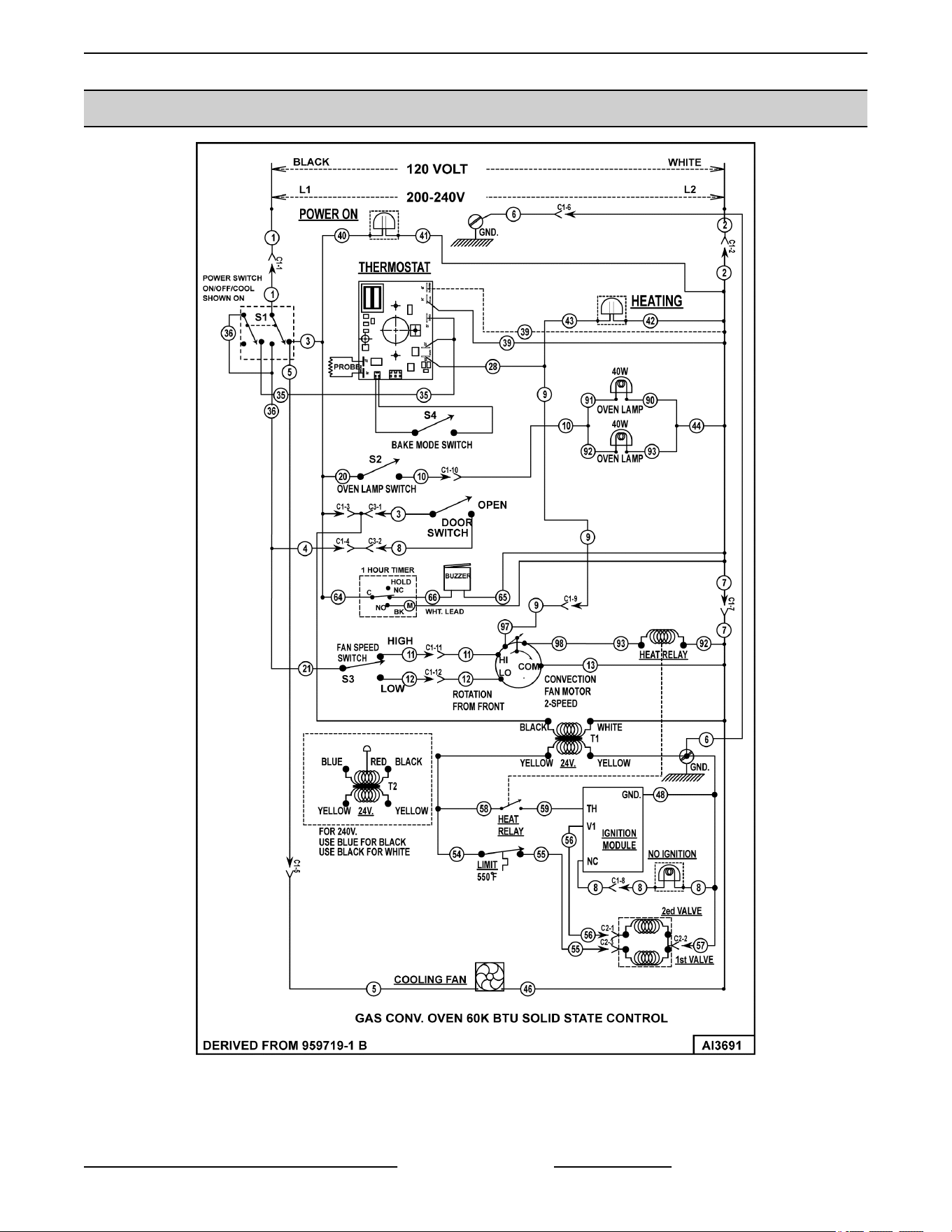
Schematic diagram AI3691 will be used to explain the
electrical sequence of operation.
Normal Cycle
1. Conditions.
A. Oven connected to correct voltage.
1) L1 (HOT) to power switch (S1).
SG SERIES GAS CONVECTION OVENS - ELECTRICAL OPERATION
F45525 Rev. B (1118) Page 38 of 46

2) L2 (NEUTRAL or SECOND LINE) to
one side of the following components:
power ON light, heat light, temperature
control board terminal T2 (120VAC) or
terminal T3 (208- 240VAC), oven
cavity lights, buzzer, "Cook" timer
motor, heat relay coil (R3), convection
fan motor common ©), transformer
primary (T1), motor speed (Hi/Low)
switch and the component cooling fan.
B. Oven properly grounded.
C. Gas supply valve ON.
D. Gas combination control valve ON.
E. Power switch (S1) OFF.
F. Oven light switch (S2) ON/OFF (position
has no affect on the function of the "Cook"
cycle).
G. Temperature control dial set to lowest
temperature (fully counterclockwise).
H. High limit switch CLOSED.
I. Timer in the OFF position.
J. Oven doors Closed.
1) Door switch contacts CLOSED.
K. Oven cavity temperature below 140°F.
2. Set temperature control dial to desired
temperature.
3. Power switch (S1) turned ON.
A. Component cooling fan energized.
B. Power ON light (Amber) comes ON.
C. Power to one side of the following
components: Timer terminal 1, transformer
primary (T1).
NOTE: Power is available to the oven light switch
(wire #20) to turn the oven cavity lights ON when the
light switch is turned ON; and power is available to the
normally open N.O. side (wire #28) of the door switch
contacts and connects power to additional
components when the door switch contacts are
CLOSED (door closed).
1) Transformer (T1) energized.
a. Power (24VAC) to one side of the
following components: heat relay
(R3) normally open (N.O.)
contacts, high limit --- connected
through the normally closed
(N.C.) contacts to the 1st valve
(safety) on the dual solenoid gas
valve.
a) 1st valve (safety) on the gas
valve energized.
NOTE: Gas does not flow to the burner until the 2nd
valve (main) is energized.
2) With door switch closed, power is
applied to motor speed switch (Hi/
Low).
a. When the convection fan motor
reaches operating speed, the
centrifugal switch (N.O.) on the
motor closes.
b. Power to normally open (N.O.)
side of internal relay contacts
(terminal 7) on the temperature
control board.
3) Power is also connected back through
a second set of contacts on the power
switch (S1) to terminal 8 on the
temperature control board.
a. Solid state temperature control
energized. If the oven
temperature is below set point,
the temperature control will
energize its internal relay. The
normally open (N.O.) contacts
close and apply power to the
following components:
a) Heat light (clear) comes ON.
b) Power is connected through
the centrifugal switch
contacts on the convection
fan motor, heat relay (R3) is
energized, (R3) contacts
(N.O.) close and the heating
circuit is powered.
c) Ignition control module is
energized.
d) No ignition light (red) comes
ON, module performs a self
diagnostic test for 4 seconds,
2nd valve (main) on the gas
valve is energized. Gas
starts to flow to the burner,
SG SERIES GAS CONVECTION OVENS - ELECTRICAL OPERATION
Page 39 of 46 F45525 Rev. B (1118)

sparking begins, the "no
ignition" light goes out and
burner lights. Sparking
continues for up to 7 seconds
or until a flame is
established. If a flame is
"sensed", the "no ignition"
light stays out and burner
remains lit. If a flame is not
"sensed" after 7 seconds of
sparking, the "no ignition"
light comes back on, 2nd
valve (main) on the gas valve
is de-energize and gas flow
to the burner stops. Ignition
trial cycle repeats after a 15
second purge between
cycles for two additional tries
before locking out. To reset
after a lockout, turn power
switch (S1) OFF then ON.
4. Oven reaches set temperature.
A. Temperature control de-energizes internal
relay and the normally open (N.O.) contacts
OPEN.
1) Heat light goes out.
2) Power removed from heat relay (R3).
a. R3 normally open (N.O.) contacts
OPEN.
a) Power removed from 2nd
valve (main) on the gas valve
and gas flow to the burner
stops.
5. The oven will continue to cycle on the
temperature control until the doors are opened or
power switch (S1) is turned to the OFF or COOL
DOWN position.
Cool Down Cycle (Solid State Temperature
Control)
1. Conditions.
A. Oven is ON.
B. Oven cavity temperature needs to be
lowered.
C. Doors are open.
1) Door switch contacts OPEN
D. Cook timer in the OFF position.
2. Power Switch (S1) turned to COOL DOWN.
NOTE: With door switch contacts OPEN (doors
open), the convection fan motor will still run and
continue to cool the oven. However, power would be
removed from the following components: Power ON
light (goes out), transformer T1 (de-energized) and to
the component cooling fan.
A. Power to motor speed switch (Hi/Low).
1) Motor speed (Hi/Low) relay (R1) is
energized and contacts change state.
a. Convection fan motor energized.
b. When Convection fan motor
reaches operating speed the
centrifugal switch on the motor
closes but no power is available
for connection to other
components.
3. If door switch is CLOSED (doors closed), power
is supplied to one side of the following
components: Power ON light (Amber), oven light
switch (S2), timer terminal 1, transformer primary
(T1) and component cooling fan.
A. Power ON light (Amber) comes ON.
B. Transformer (T1) energized.
1) Power (24VAC) to one side of the
following components: heat relay (R3)
normally open (N.O.) contacts, high
limit --- connected through the normally
closed (N.C.) contacts to the 1st valve
(safety) on the dual solenoid gas valve.
a. 1st valve (safety) on the gas valve
energized.
NOTE: Gas does not flow to the burner until the 2nd
valve (main) is energized.
4. The oven will remain in this condition until the
power switch (S1) is turned to the OFF or ON
position.
SG SERIES GAS CONVECTION OVENS - ELECTRICAL OPERATION
F45525 Rev. B (1118) Page 40 of 46
SCHEMATICS
ENDING AT PRODUCTION DATE OF 3/18/2018
SG SERIES GAS CONVECTION OVENS - ELECTRICAL OPERATION
Page 41 of 46 F45525 Rev. B (1118)
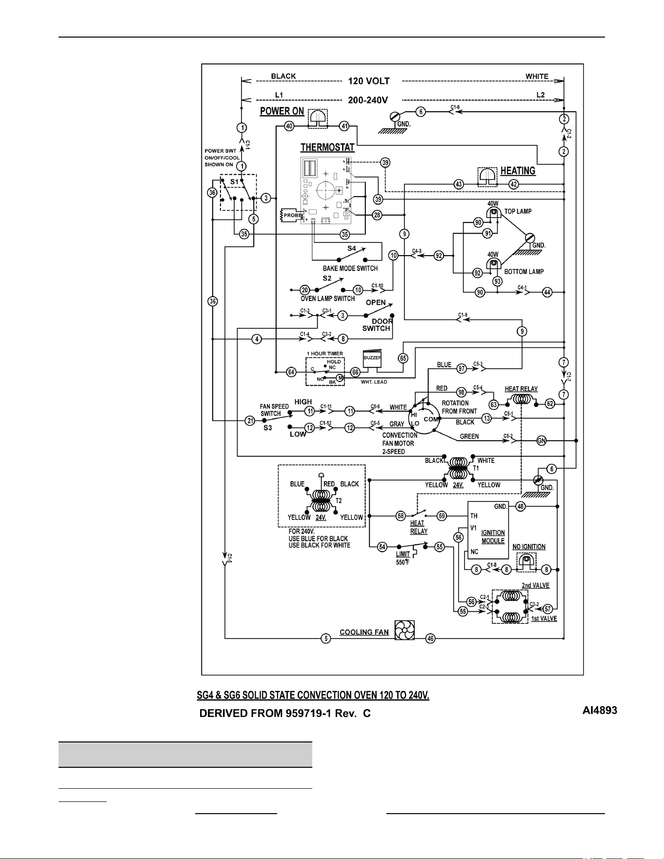
STARTING AT PRODUCTION DATE OF 3/19/2018
WIRING DIAGRAM
See Wiring Diagram AI3692 for production date up to
3/18/2018
SG SERIES GAS CONVECTION OVENS - ELECTRICAL OPERATION
F45525 Rev. B (1118) Page 42 of 46
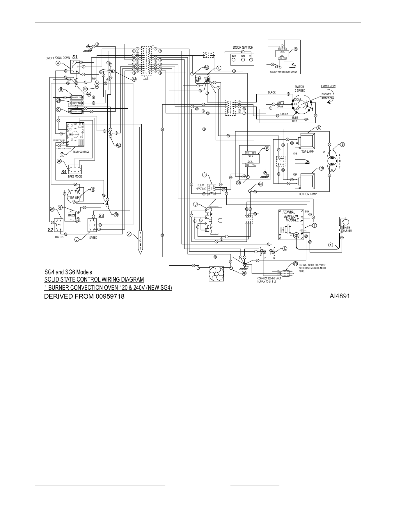
STARTING AT PRODUCTION DATE OF 3/19/2018
SG SERIES GAS CONVECTION OVENS - ELECTRICAL OPERATION
Page 43 of 46 F45525 Rev. B (1118)
TROUBLESHOOTING
Certain procedures in this section require electrical test or measurements while power is
applied to the machine. Exercise extreme caution at all times and follow Arc Flash procedures.
If test points are not easily accessible, disconnect power and follow Lockout/Tagout
procedures, attach test equipment and reapply power to test.
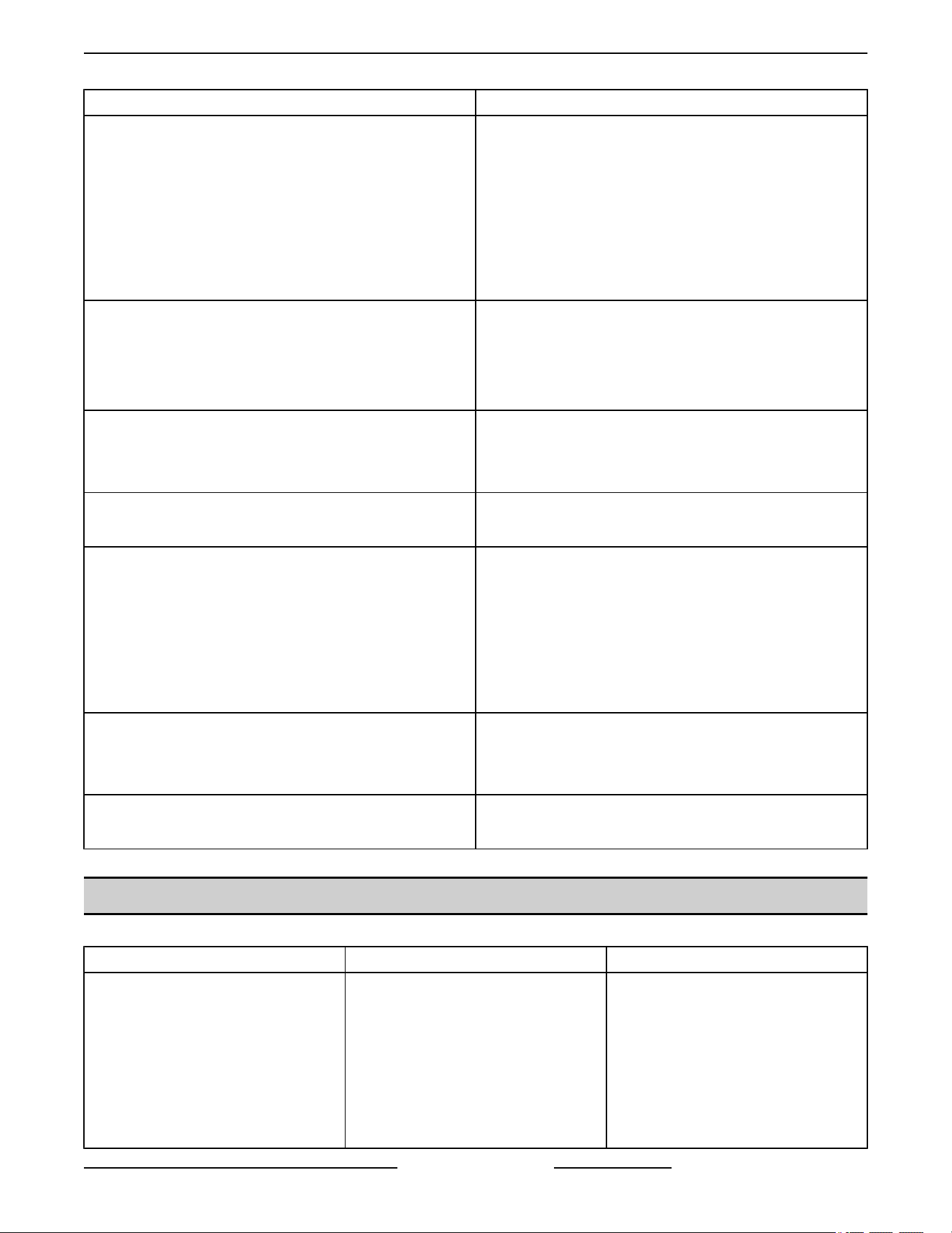
ALL MODELS
SYMPTOMS POSSIBLE CAUSES
Blower motor doesn’t run with 1S in “Cool Down” or “On”
position.
1. Line voltage.
2. Power switch (S1) malfunction.
3. Switch (S3) malfunction.
4. Interconnecting wiring malfunction.
5. Motor inoperable.
Blower motor doesn’t run in “On” position. “Cool Down”
functions OK.
1. Door switch malfunction.
2. Power switch contacts inoperative.
3. Interconnecting wiring malfunction.
Blower motor doesn’t run in “Cool Down” position. Runs
OK in “On” position.
1. Power switch malfunction.
2. Interconnecting wiring malfunction.
Gas does not ignite; No spark; No Ignition Light ON.
1. Shorted electrode on ignitor/flame sense.
2. Ignitor cable (high voltage) OPEN.
3. Heat relay (R3) malfunction.
4. Transformer (T1) inoperative.
5. High limit thermostat open.
6. Interconnecting wiring malfunction.
7. Ignition Module malfunction.
Sparks but gas does not ignite.
1. Gas solenoid valve OFF or inoperative.
2. Manual gas valve CLOSED.
3. Gas supply OFF or Insufficient gas pressure.
4. Interconnecting wiring malfunction.
5. Ignition Module malfunction.
SG SERIES GAS CONVECTION OVENS - TROUBLESHOOTING
F45525 Rev. B (1118) Page 44 of 46
SYMPTOMS POSSIBLE CAUSES
Gas ignites but will not maintain flame.
1. Igniter lead connections malfunction.
2. Ignitor ground inoperative.
3. Ignitor/flame sense malfunction.
4. Insufficient gas pressure.
5. Snorkel vent plugged, obstructed or missing.
6. Incorrect polarity from transformer (T1) to Ignition
module.
Excessive or low heat.
1. Temperature probe malfunction.
2. Temperature control board malfunction.
3. Gas pressure Insufficient.
4. Gas orifice plugged or obstructed.
Mechanical Timer inoperative or not functioning properly.
1. Interconnecting wiring malfunction.
2. Line voltage incorrect.
3. Timer malfunction.
Component cooling Fan does not run.
1. Motor inoperable.
2. Interconnecting wiring malfunction.
Uneven Cooking.
1. Convection Fan motor speed/direction.
2. Poor combustion.
A. Gas pressure incorrect.
B. Exhaust vent plugged or obstructed.
C. Snorkel Vent plugged or obstructed.
3. Air flow Baffles missing or damaged.
Intermittent problems.
1. High ambient temperatures.
2. Wiring connections loose.
3. Cooling fan malfunction.
No power to temperature control.
1. Power switch (S1) in “Cool Down”.
2. Door or door switch open.
IGNITION MODULE DIAGNOSTICS
NUMBER OF LED FLASHES INDICATES POSSIBLE CAUSE
2 Flashes Burner flame with no call for heat.
1. Main gas valve stuck open,
burner on with no call for heat
from the temperature control
system. Replace main gas
valve.
2. Check flame sensor and sensor
wire.
3. Ignition module malfunction.
SG SERIES GAS CONVECTION OVENS - TROUBLESHOOTING
Page 45 of 46 F45525 Rev. B (1118)
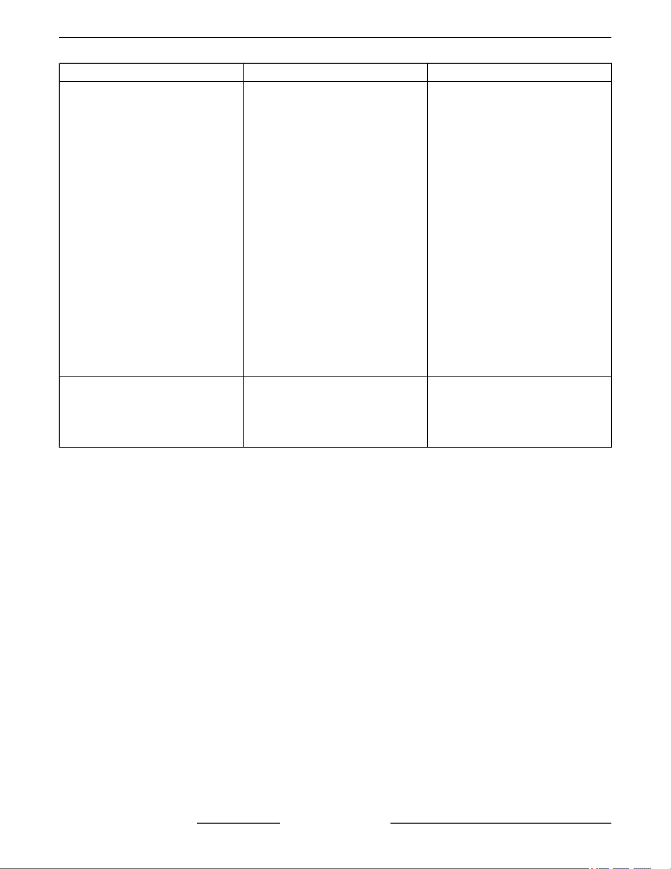
NUMBER OF LED FLASHES INDICATES POSSIBLE CAUSE
3 Flashes Ignition system has locked out.
1. Ignition module could not
“Prove” flame after three tries for
ignition within the lockout time
timing provided.
A. Check for gas supply to
burner.
B. Check for spark to ignition
electrode.
1) Check spark gap (gap
should be 1/8").
C. Check for flame current in
flame sense wire (0.000001
Amp Min. DC) using FC
designated terminals.
1) Check burner
adjustment (air/gas).
NOTE: If A thru C check
out, replace ignition
module.
4 Flashes Internal board problem.
1. Ignition module malfunction.
Remove power from “R” terminal
for five seconds then reconnect.
If fault remains, replace ignition
module.
SG SERIES GAS CONVECTION OVENS - TROUBLESHOOTING
F45525 Rev. B (1118) Page 46 of 46