1
ITEM #5249294
MODEL #HTE22023
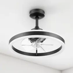
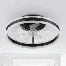
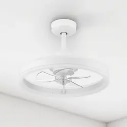
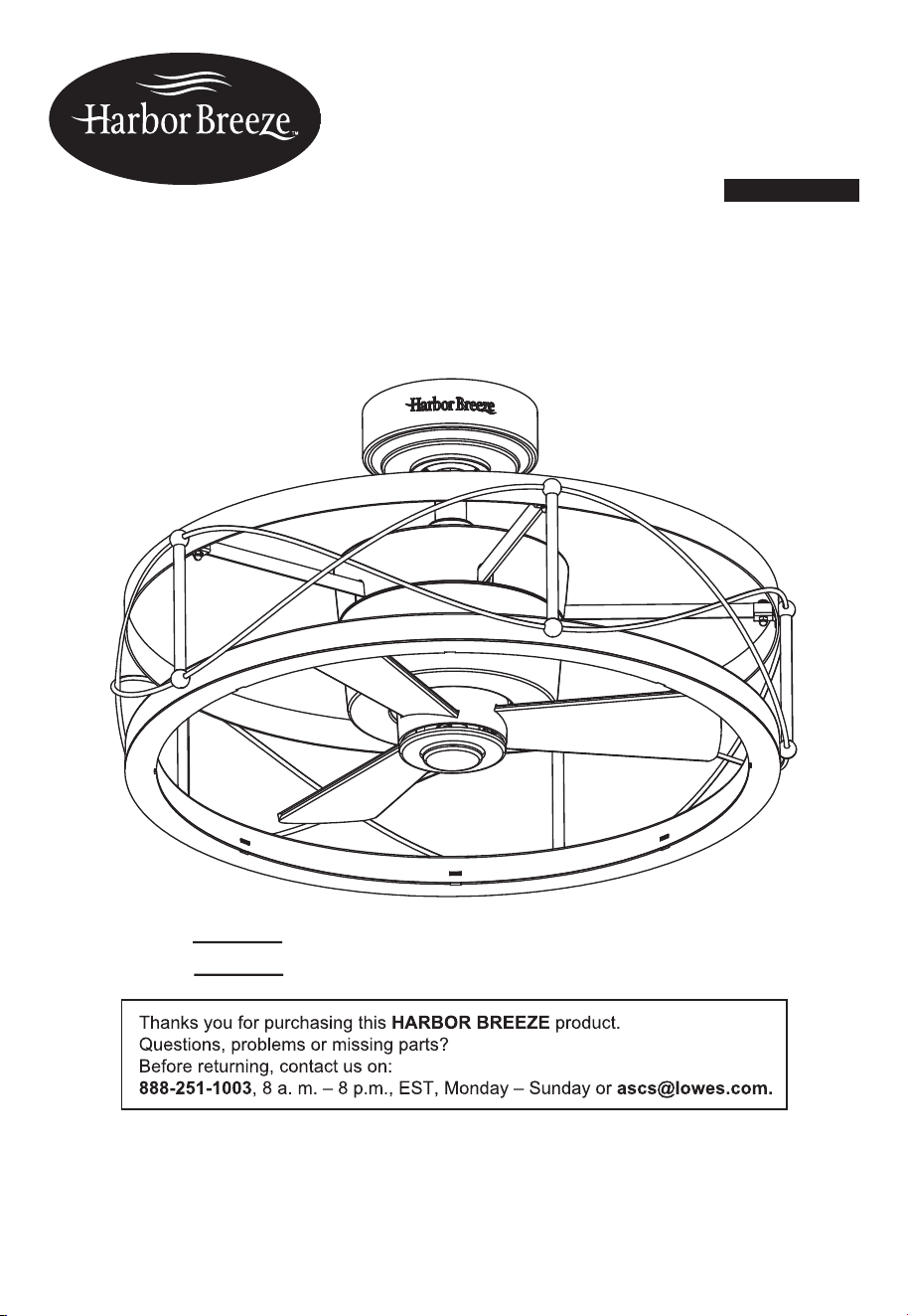
YORKMONT FAN
ATTACH YOUR RECEIPT HERE
HARBOR BREEZE and logo design are
trademarks or registered trademarks of
LF, LLC. All rights reserved.
SG241057
Serial Number
Purchase Date
Español p. 18

2
TABLE OF CONTENTS
Package Contents..............................................................................................................
Hardware Contents............................................................................................................
Safety Information..............................................................................................................
Preparation .......................................................................................................................
Initial Installation Instructions ............................................................................................
Standard/Angle-Mounting Instructions...............................................................................
Wiring Instructions .............................................................................................................
Final Installation Instructions ............................................................................................
Operating Instructions ......................................................................................................
Care and Maintenance .....................................................................................................
Troubleshooting..................................................................................................................
Limited Lifetime Warranty....................................................................................................
Replacement Part List ......................................................................................................
3
4
4
5
6
7
9
10
11
13
14
15
FCC Warning......................................................................................................................
16
17
3
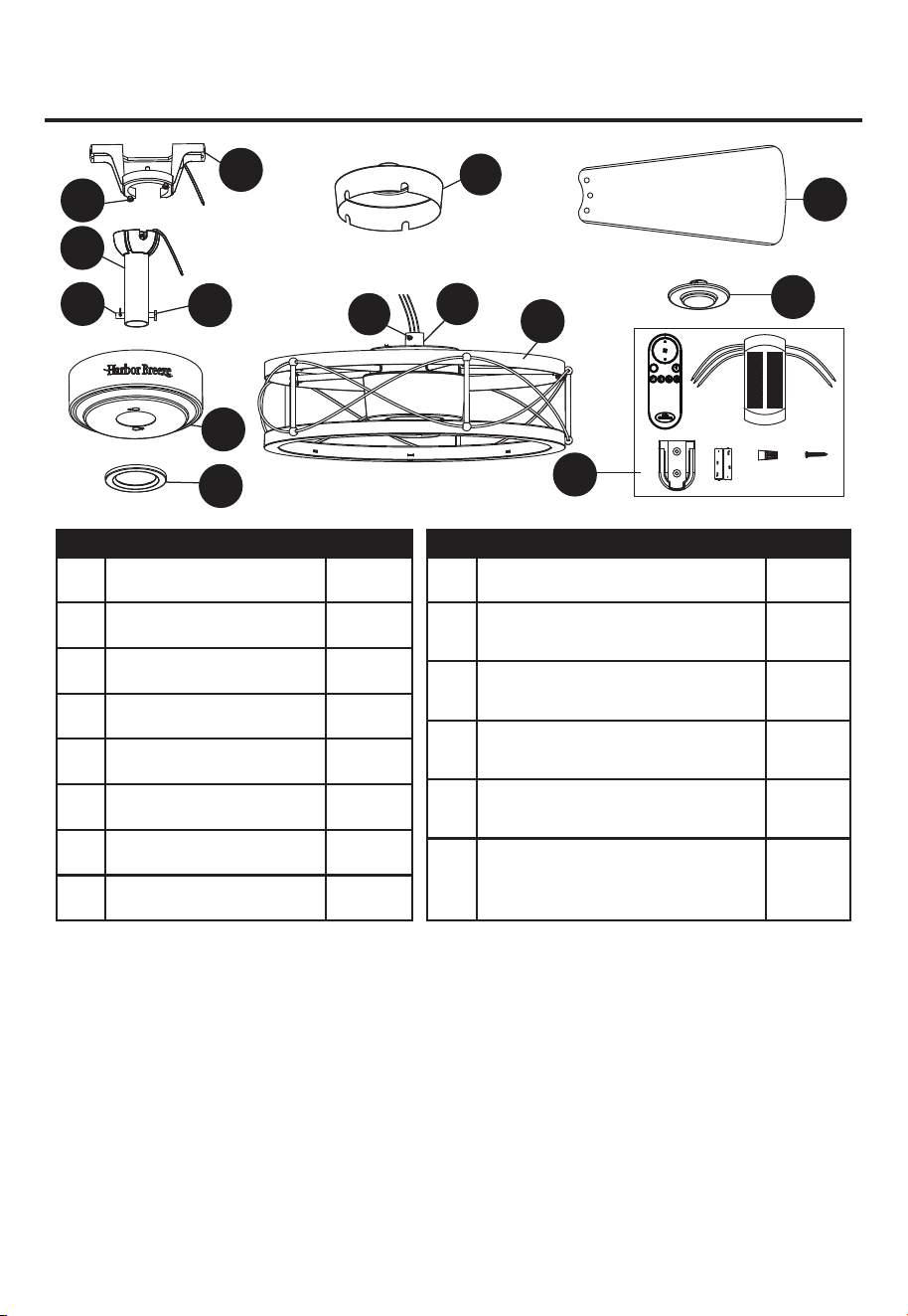
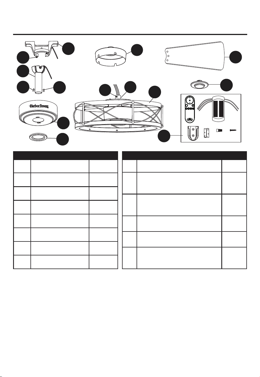
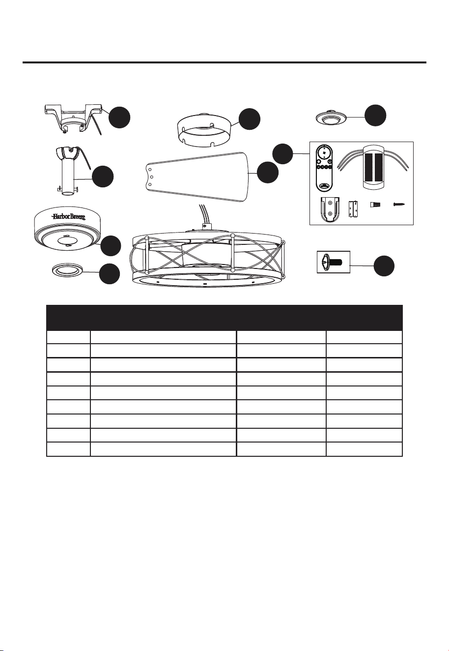
PACKAGE CONTENTS
I
A
N
B
J
K
C
D
E
F
H
G
M
L
DIM
R
X2
X6
PART DESCRIPTION QUANTITY PART DESCRIPTION QUANTITY
L
I
J
K
M
N
1
1
1
1
1
2
2
A
B
C
D
E
F
G
1
1
1
1
1
3
1
Mounting Bracket
Steel Cap
Remote Unit
Clevis Pin(preassembled on
Downod Assembly (B))
Hairpin Clip(preassembled on
Downod Assembly (B))
Coupling(preassembled on
Motor Assembly (G))
Coupling Screw
(preassembled on Coupling (L))
Mounting Bracket Screw
(preassembled on Mounting
Bracket (A))
Downrod Assembly
Canopy
Canopy Cover
Coupling Cover
Blade
Motor Assembly
H
4
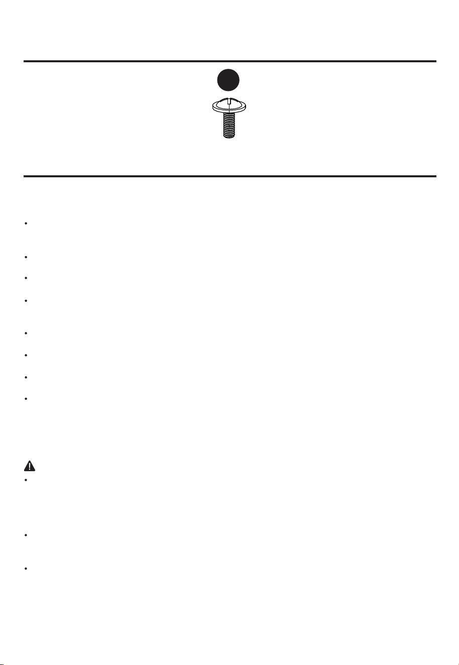
HARDWARE CONTENTS (not shown actual size)
AA
Qty. 9 +1 extra
Blade Screw
SAFETY INFORMATION
READ AND SAVE THESE INSTRUCTIONS
Please read and understand this entire manual before attempting to assemble, operate or install the
product.
All electrical connections must comply with local codes, ordinances or the National Electric Code
(NEC).Contact your municipal building department to inquire about your local codes, permits and/or
inspections.
Turn off electricity at main fuse box (or circuit breaker box) before beginning installation by removing
fuse or by switching off circuit breaker.
Do not connect this fixture to an electrical system that does not provide a means for equipment
grounding.Never use a fixture in a two-wire system that is not grounded.
If you are not sure your lighting system has a grounding means, do not attempt to install this fixture.
Contact a qualified, licensed electrician for information regarding proper grounding methods as
required by the local electrical code in your area.
Make sure the installation site you choose allows a minimum clearance of 7 ft. from the blades to
the floor and at least 30 in. from the ends of the blades to any obstruction.
If a dimmer control switch is used with this fixture, obtain professional advice to determine the
correct type and electrical rating required.
The lighting fixture must be positioned so there is at least 1.64 ft. between the bulb and any
illuminated surface.
For supply connections, if the conductor of a fan is identified as a grounded conductor, then it
should be connected to a grounded conductor power supply. If the conductor of a fan is identified as
an ungrounded conductor, then it should be connected to an ungrounded conductor power supply. If
the conductor of a fan is identified for equipment grounding, then it should be connected to an
equipment-grounding conductor.
Installing a fixture into an electrical system without a proper grounding means could allow metal
parts of the fixture to carry electrical currents. If any of the fixture wires, wire connections or splices
are broken, cut or loose during the mounting or normal operation of the fixture, under such condition,
anyone coming in contact with the fixture is subject to electrical shock, which could cause serious
injury or death.
Connection of the bare or green fixture ground wire to the black or white house wires may allow
metal parts of the fixture to carry electrical currents. Under this condition anyone coming in contact
with the fixture will receive electrical shock, which could cause serious injury or death.
Be careful not to damage or cut the wire insulation (covering) during fixture installation. Do not
permit wires to have contact with any surface having a sharp edge. Doing so may damage or cut the
wire insulation, which could cause serious injury or death from electric shock.
DANGER
5
WARNING
CAUTION
PREPARATION
Risk of fire. Most dwellings built before 1985 have supply wire rated for 140°F. Consult a qualified
electrician before installation.
To reduce the risk of fire or electric shock, do not use this fan with any solid state fan speed device
or variable speed control.
To reduce the risk of personal injury, do not bend the blade brackets when installing the brackets,
balancing or cleaning the fan.
Do not insert foreign objects in between rotating fan blades.
Do not install or use the fan if any part is damaged or missing.
To reduce the risk of fire, electric shock or personal injury, mount to metal outlet box marked
'ACCEPTABLE FOR FAN SUPPORT OF 35 LBS OR LESS' and use mounting screws provided
with the outlet box and/or support directly from building structure. Most outlet boxes commonly
used for the support of luminaries are not acceptable for fan support and may need to be replaced.
Consult a qualified electrician if in doubt.
Before servicing or cleaning the unit, switch power off at the service panel and lock the service
disconnecting means to prevent power from being switched on accidentally. When the service
disconnecting means cannot be locked, securely fasten a prominent warning device, such as a tag,
to the service panel.
Do not use lamp having a wattage greater than the maximum value stated on the fixture and in this
manual. Using a higher wattage lamp than specified will increase fixture temperature and increase
risk of fire.
Before beginning assembly of product, make sure all parts are present. Compare parts with package
contents list and hardware contents list. If any part is missing or damaged, do not attempt to assemble
the product.
Estimated Assembly Time: 45 minutes.
Tools Required for Assembly (not included): Phillips Screwdriver, Step Ladder, Tape, Pliers and Wire
Cutters.
6
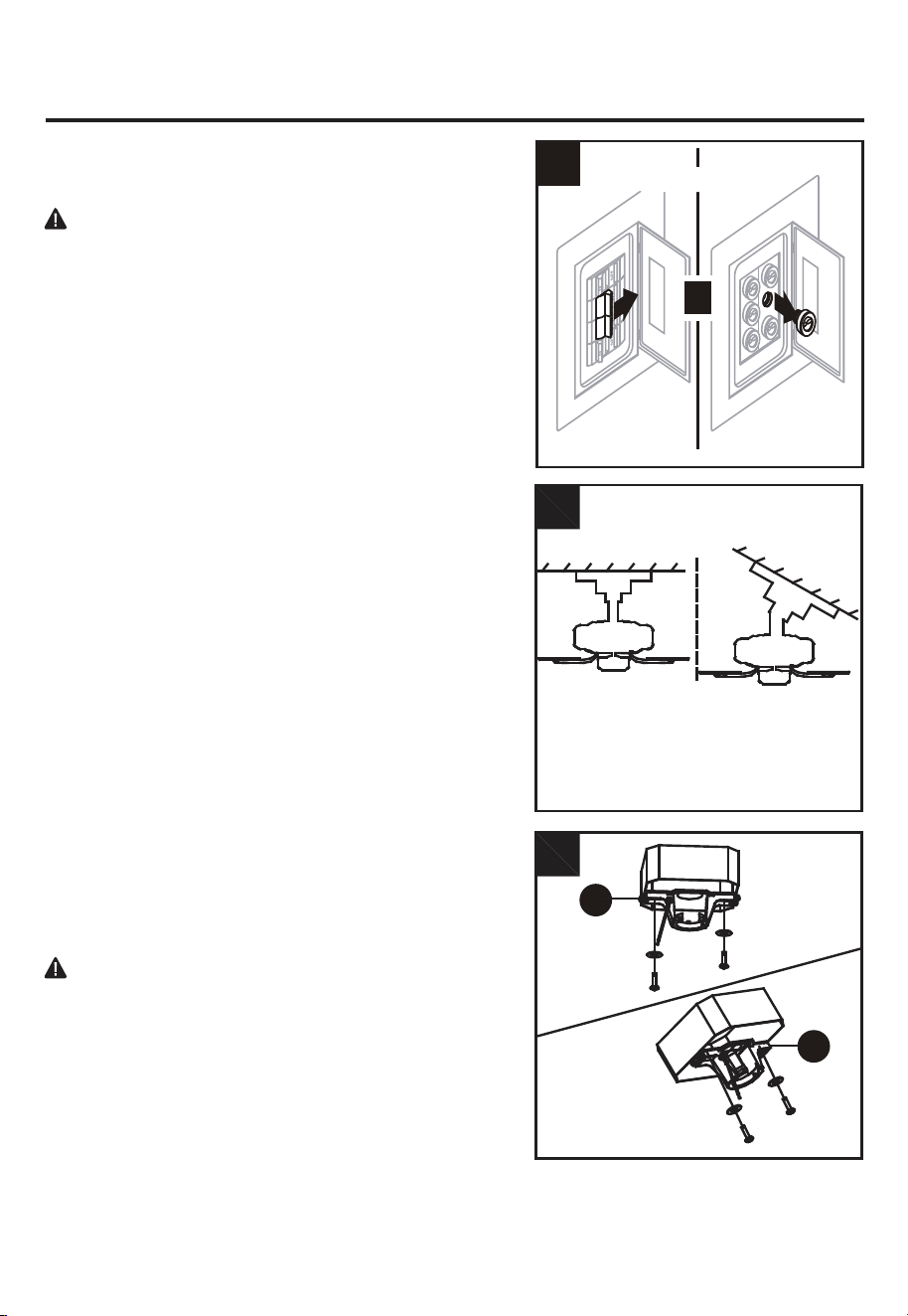
INITIAL INSTALLATION INSTRUCTIONS
DANGER:
A. Standard Mounting:
B. Angle Mounting:
Failure to disconnect power supply prior to
1.
Turn off circuit breakers and wall switch to the fan supply
line leads.
2. Choose the desired mounting method:
Standard mounting is best suited for ceilings 8 feet. or
higher. For taller ceilings you may want to use a longer
downrod (not included).
Angle-style mounting is best suited for angled or vaulted
ceilings. A longer downrod is sometimes necessary to
ensure proper blade clearance. If using the angle mount,
make sure the ceiling angle is not steeper than 20°.
3.
Check existing outlet box (not included) to ensure it is
securely fastened to at least two points in a structural
ceiling member and can support the full weight of the fan.
Once verified, install mounting bracket (A) to the outlet
box using the screws and washers provided with the
outlet box.
installation may result in serious injury or death.
DANGER:
A loose outlet box can cause the fan to
Note:
If using the angle mount, make sure open end of
wobble and increase the fan’s potential to fall, which
mounting bracket (A) points toward the ceiling.
could result in serious injury or death.
For ALL mounting options, there must be at least 30 inches
from the blade tip to nearest wall. Also, ensure there is 7
feet from the bottom edge of the blade to the floor.
A
B
2
3
Standard
Mounting
A
Angle
Mounting
A
or
T
Turn Off Power Source
1
777
INITIAL INSTALLATION INSTRUCTIONS
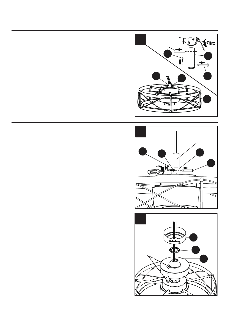
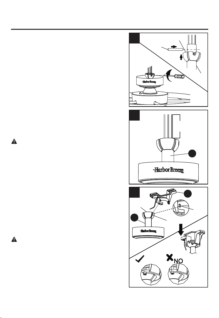
4. Remove the clip (K) and the cross pin (J) from the
downrod assembly (B). Loosen the coupling screws (M)
on the coupling (L).
Remove the hanger ball portion from the downrod
assembly (B) by loosening the set screw in the hanger
ball until the ball falls freely down the downrod. Remove
the pin from the downrod, then remove the hanger ball.
Retain the pin and hanger ball for reinstallation.
Note:
Make sure to keep loose hardware separate to
avoid confusion during installation.
STANDARD/ANGLE-MOUNTING INSTRUCTIONS
1.
Feed power wires from motor assembly through downrod,
then insert downrod into the coupling (L) on motor
assembly. Align the hole on downrod to hole on
coupling (L), then re-install clevis pin (J). Re-attach
hairpin clip (K) into clevis pin (J) until it snaps into place,
then tighten the two previously loosened coupling
screws (M).
G
M
L
J
B
K
4
1
2.
Must be aligned
Route wires through coupling cover (E), canopy cover (D)
and canopy (C). Align the rectangular hole of the coupling
cover (E) to the reverse switch of motor assembly.
C
D
E
2
Hanger ball
Pin
L
K
M
J
Downrod
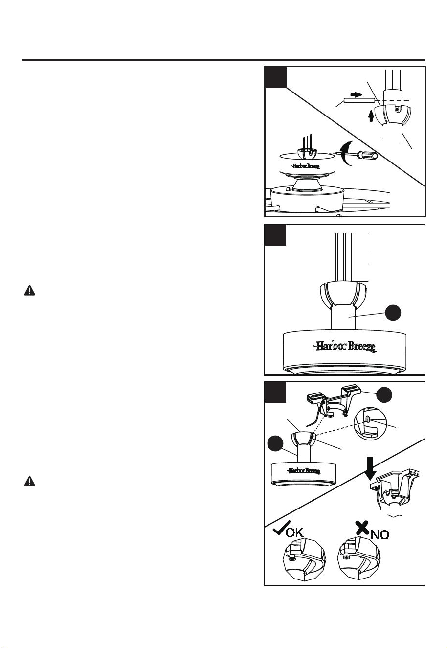
5. Carefully lift the assembly and rest the hanger ball of
downrod assembly (B) on the mounting bracket (A)
attached to the outlet box. Be sure the groove in the
hanger ball is lined up with the tab on the mounting
bracket (A). This will allow for hands-free wiring.
Proceed to WIRING on page 9.
DANGER: Be careful when aligning the tab to the
groove ! If not fully engaged, there is a possibility of the
fan falling, which may result in serious injury or death.
A
5
Hanger Ball
Groove
Tab
B
Hanger ball
Pin
Downrod
Reinstall the hanger ball on the downrod as follows.
Route the black, white and blue wires through the hanger
ball. Position the pin through the two holes in the downrod
and align the hanger ball so the pin is captured in the
groove in the top of the hanger ball. Pull the hanger ball
up tight against the pin. Securely tighten the set screw in
the hanger ball. A loose set screw could create fan
wobble.
3.
3
CAUTION:
Ensure all screws are tight before moving
onto the next step.
4. Cut off excess fixture wires, leaving approximately 6 to
9 inches above the top of the downrod assembly (B).
Strip 1/2 inch of insulation from the end of each fixture
wire.
4
B
6 to 9 in.
STANDARD/ANGLE-MOUNTING INSTRUCTIONS
8
9
WIRING INSTRUCTIONS
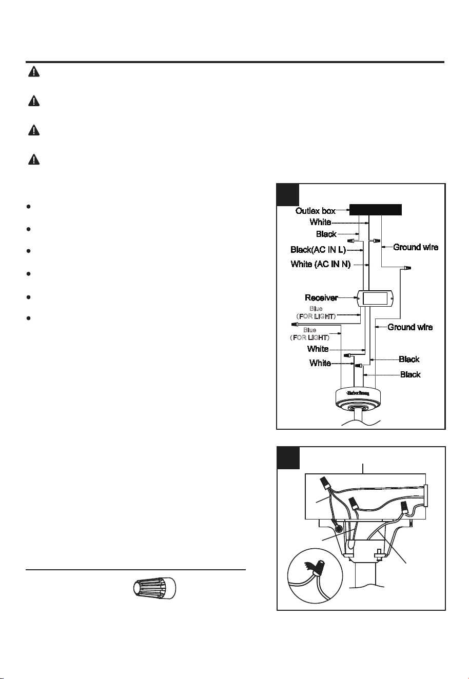
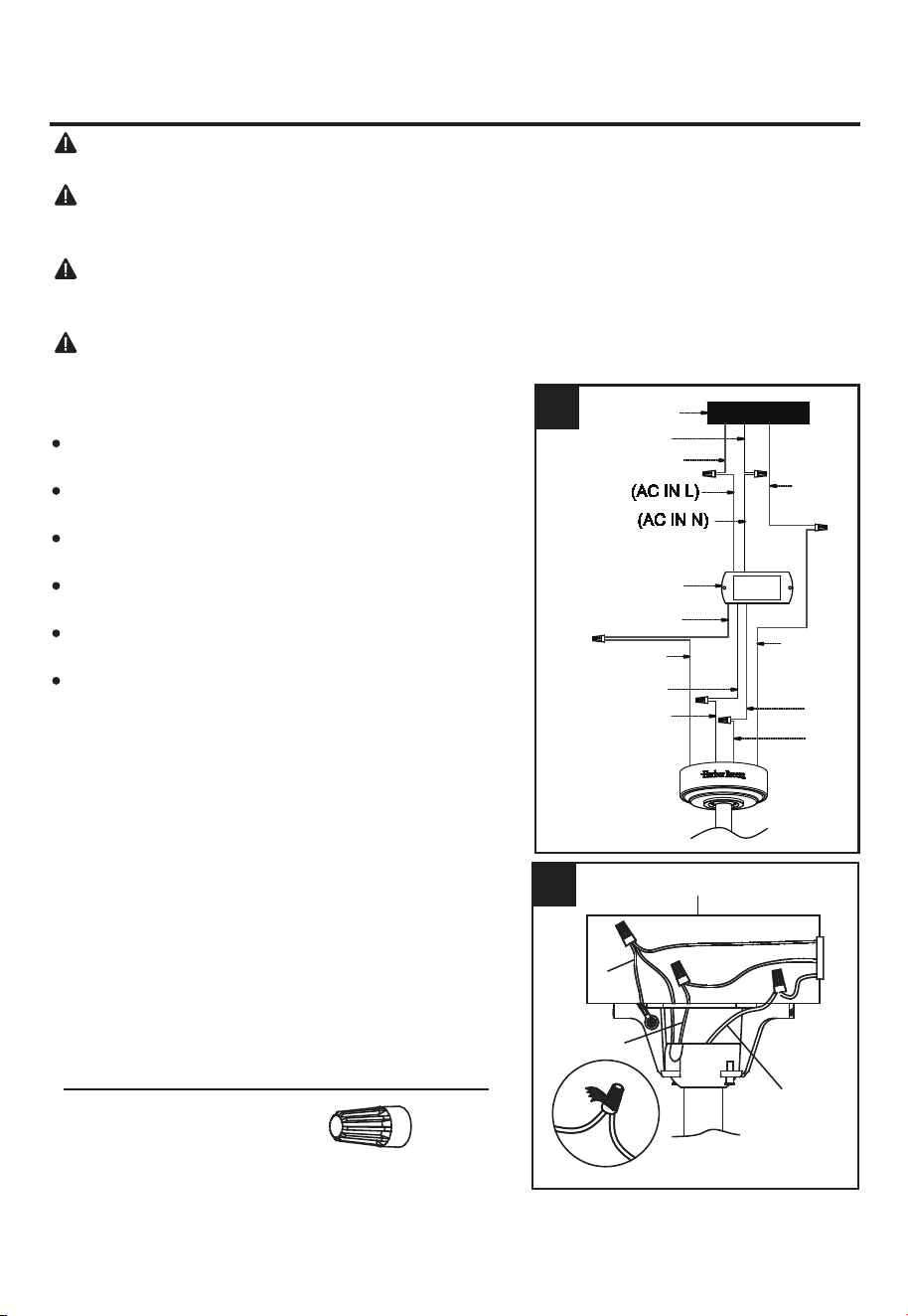
1. Follow steps below to wiring your fan.
Connect WHITE wire from the fan to WHITE wire marked
TO MOTOR N from the receiver.
Connect BLUE wire from the fan to BLUE wire marked
FOR LIGHT from the receiver.
Connect BLACK wire from the fan to BLACK wire
marked TO MOTOR L from the receiver.
Connect BLACK wire from the outlet box to BLACK wire
marked AC IN L from the receiver.
Connect WHITE wire from the outlet box to WHITE wire
marked AC IN N from the receiver.
Connect GROUND (GREEN) wires from mounting
bracket and downrod ball, to GROUND (GREEN or
BARE COPPER) from house.
WARNING:
To avoid possible electrical shock, be sure electricity is turned off at the main fuse
box before hanging.
WARNING:
If you are not sure if the outlet box is grounded, contact a licensed electrician for
advice, as it must be grounded for safe operation.
WARNING: If house wires are different colors than referred to in the following steps, stop
immediately. A professional electrician is recommended to determine proper wiring.
WARNING: If you feel that you do not have enough electrical wiring knowledge or experience,
have your fan installed by a licensed electrician.
1
Blue
(FOR LIGHT)
Blue
(FOR LIGHT)
2
BLACK
WHITE
GREEN
Outlet Box
2. Wrap electrical tape (not included) around each wire
connector and make sure no bare wire or wire strands
are visible after making connections. Then, turn wires
upward and carefully push them into the outlet box;
make sure the WHITE and GREEN connections are on
one side and the BLACK connections are on the other
side.
Hardware Used
Wire Connector x 6
WIRING INSTRUCTIONS
10
FINAL INSTALLATION INSTRUCTIONS
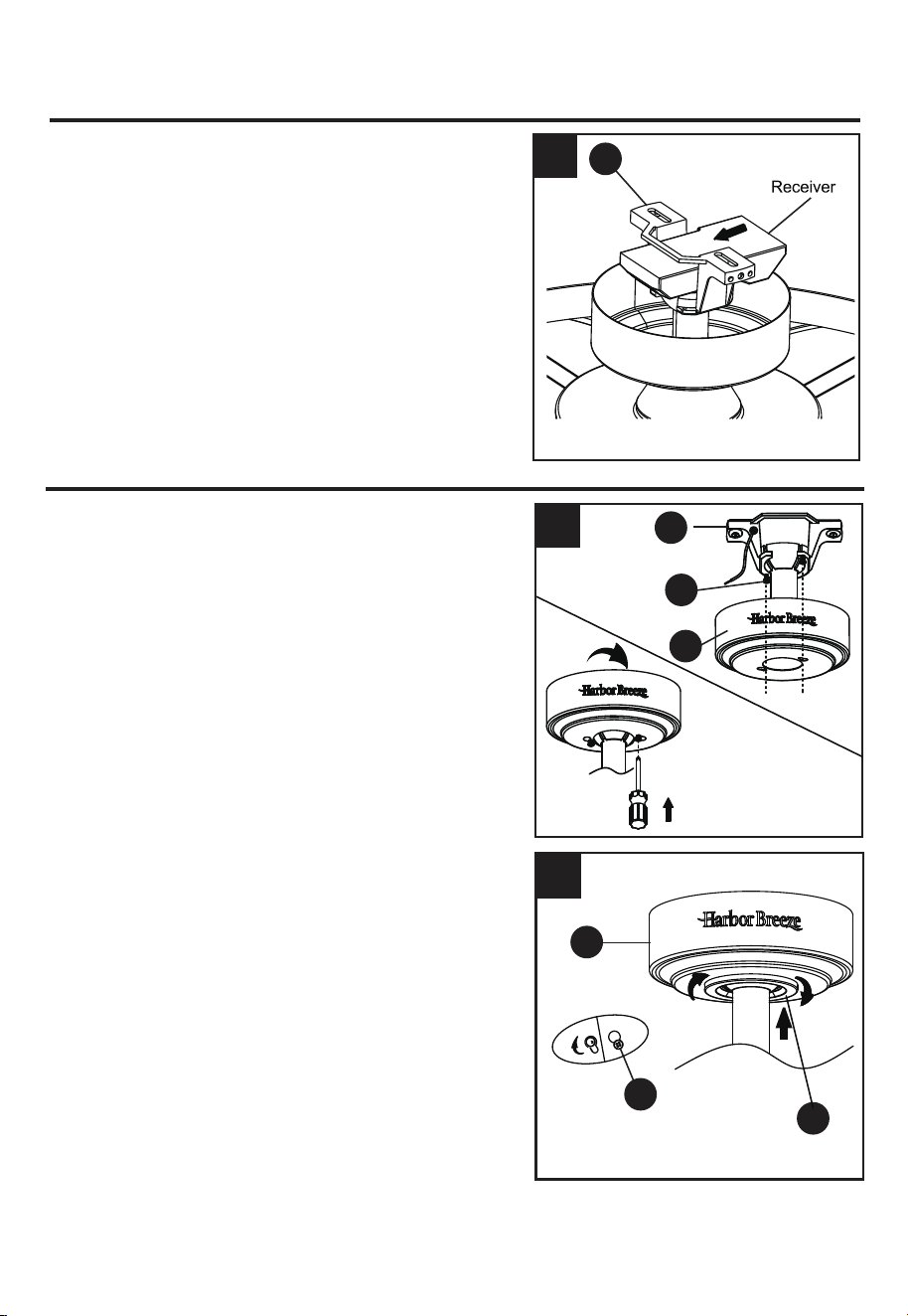
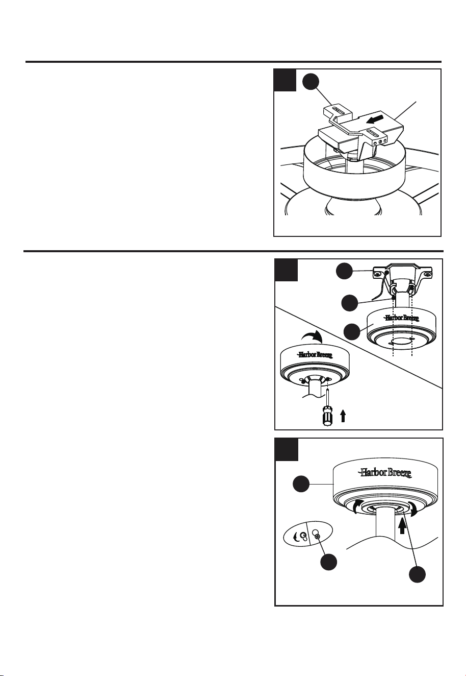
1. Loosen (but do not remove) the two preassembled
mounting screws (N) on mounting bracket (A) that align
with the slotted holes on canopy (C). Lift canopy (C) up
so slotted holes engage loosened screw heads on
mounting bracket (A), then twist canopy (C) clockwise,
then tighten all screws securely.
2. Raise canopy cover (D) over the mounting screws (N)
visible in canopy (C). Rotate canopy cover (D) clockwise
until it locks into place. You may need to adjust the
mounting screws (N) until the canopy (C) and canopy
cover (D) have a snug fit.
1
A
N
C
2
C
N
D
3
3. Once wiring step has been completed, slide the wired
receiver in between the mounting bracket (A) and the
top of the downrod assembly (B) with the flat side of
the receiver facing the ceiling.
A
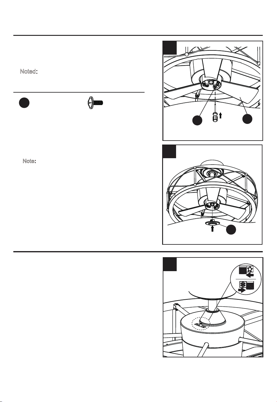
11
4 .
OPERATING INSTRUCTIONS
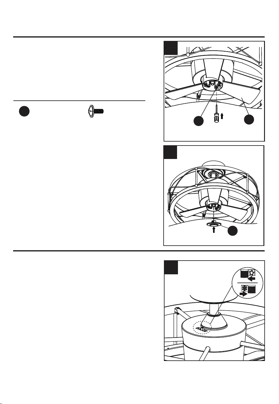
1. When the season changes, you may want to change
the direction in which the fan spins.
In warmer weather, counterclockwise rotation creates a
downward airflow, which cools the air. Push the switch
LEFT and see a SUN icon.
In cooler weather, clockwise rotation creates an upward
airflow,which moves hot air from the ceiling. Push the
switch
RIGHT and see a SNOWFLAKE icon.
WARNING:
Turn off and wait for fan to stop before
flipping the reverse switch.
Note: Use a small screwdriver or ballpoint pen to move
the reverse switch if you have difficulty doing so by
hand.
Attach the steel cap (H) to the motor shaft, and rotate
it until it is in place.
Note:
Do not overtighten the steel cap (H).
H
4
1
FINAL INSTALLATION INSTRUCTIONS
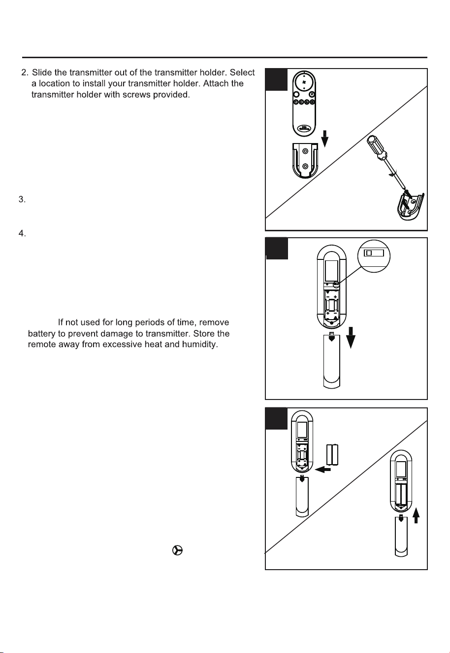
3.
Hardware Used
Blade Screw x 9
AA
Slide blades (F) through slots in the flywheel and
attach to the motor hub using the blade screws (AA).
Make sure the screws securing the blades (F) to the
motor hub are tight and are properly seated.
Noted: Periodically check blade hardware and resecure
if necessary.
F
3
AA
12
OPERATING INSTRUCTIONS
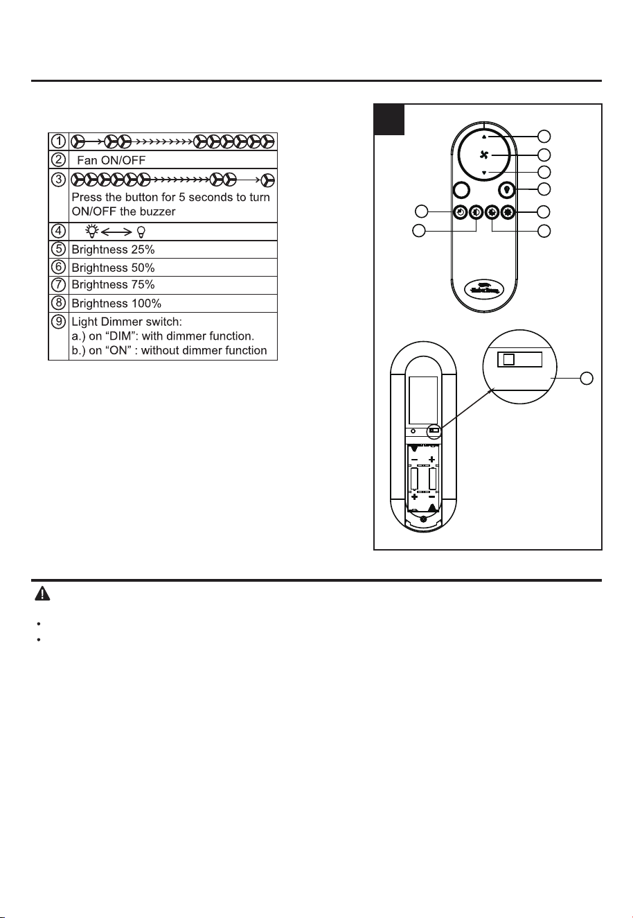
NOTE: Each transmitter of this remote control carries a
unique ID code to facilitate communication between
paired devices. The ID code is set by factory and is not
user changeable. However, you will be required to
perform an “ID code learning ” process manually under
these circumstances:
•When your remote control is not responding (make sure
• If you have multiple fans installed within a close
Open the battery cover.
proximity and want to control all fans using a same
remote transmitter.
NOTE: Each fan requires its own receiver.
NOTE:
battery is not flat)
•After you have replaced a faulty transmitter or receiver
with a new one.
Otherwise the remote control will not work. To perform
this process manually, follow steps below:
After installing and wiring the unit, restore power to your
fan, press and hold the transmitter “ ” button for 5
seconds until the fan beeps to indicate the code learning
process have been completed. This operation must be
completed within 1 minute after restore power to the fan.
.
3
4
2
DIM
R
ON
DIM
ON
A
UM-4 1.5VX2
A
A
A
A
A
FCC ID:M8C-EEC118RF433
DIM
This device complies with part 15 of the
FCC Rules. Operation is subject to the
following two conditions: (1)This device
may not cause harmful interference,
and (2)this device must accept any
Interference that may cause undesired
operation
A
UM-4 1.5VX2
A
-
+
AAA
A
A
A
A
-
+
A AA
DIM
ON
FCC ID:M8C-EEC118RF433
This device complies with part 15 of the
FCC Rules. Operation is subject to the
following two conditions: (1)This device
may not cause harmful interference,
and (2)this device must accept any
Interference that may cause undesired
operation
DIM
ON
FCC ID:M8C-EEC118RF433
This device complies with part 15 of the
FCC Rules. Operation is subject to the
following two conditions: (1)This device
may not cause harmful interference,
and (2)this device must accept any
Interference that may cause undesired
operation
To make fan operational, install two 1.5 V AAA batteries
(included). Replace the battery cover.
NOTE: This remote control uses two 1.5 V AAA batteries.
Replace batteries with the correct size and type of battery.
Clean the battery contacts and area inside the device
prior to installing new batteries. Ensure the batteries are
installed correctly with regard to the polarity ( + and -).
CARE AND MAINTENANCE
Important: Shut off main power supply before beginning any maintenance. Do not use water or a
damp cloth to clean the ceiling fan.
At least twice each year, tighten all screws and lower canopy to check mounting plate screws.
Clean fan housing with only a soft brush or lint-free cloth to avoid scratching the finish. Clean blades
with a lint-free cloth. You may occasionally apply a light coat of furniture polish to wood blades for
added protection.
13
OPERATING INSTRUCTIONS
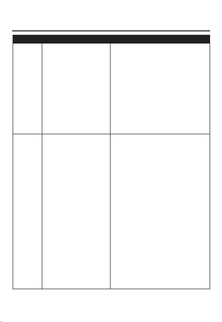
5. The buttons on the remote control the fan speed and
light as follows:
NOTE: This receiver has a preset memory function;
when the switch is turned OFF, the control will
remember the light intensity and fan speed. When the
switch is turned ON, the light and fan will resume
operation as they were prior to the switch being turned
OFF.
NOTE: Factory set is on “DIM” position.
5
ON
DIM
ON
A
UM-4 1.5VX2
A
A
A
A
A
FCC ID:M8C-EEC118RF433
DIM
9
This device complies with part 15 of the
FCC Rules. Operation is subject to the
following two conditions: (1)This device
may not cause harmful interference,
and (2)this device must accept any
Interference that may cause undesired
operation
DIM
1
2
3
4
7
8
5
6
R
TROUBLESHOOTING
14
1. Set screws are loose.
2. Using non-approved speed
control.
3. Normal noise.
4. Wire connectors inside switch
housing rattling.
5. Cracked blade.
6. The distance from canopy to
ceiling is too great.
7.Glass is not secure.
1. Tighten all set screws.
2. Some fan motors are sensitive to signals
from solid-state varible speed controls. DO
NOT USE a solid-state variable speed control.
3. Allow "break-in" period of 24 hours. Most
noises associated with a new fan will disappear
after this period.
4. Check to make sure wire connectors in
switch housing are not rattling against each
other or against the interior wall of the switch
housing.
5. Replace blades.
6. Make sure upper canopy is a short distance
from ceiling. It should not touch the ceiling.
7. Secure the glass.
1. Hanger bracket and/or ceiling
outlet box is not securely
fastened.
2. Set screw in downrod
assembly is loose.
3. Fan hanger ball is not properly
seated in canopy tabs.
4. Set screw in motor coupling is
loose.
5. Blade is loose.
6. Blade holders are loose.
7. Blade out of balance.
8. Fan too close to vaulted
ceiling.
9. Transition to different speed.
10. Fan not securely mounted.
1. Tighten the hanger bracket screws to the
outlet box,and/or secure outlet box.
2. Tighten the set screw in the downrod
assembly.
3. Turn power off, support the fan very carefully,
and check that the hanger ball is properly seated.
4. Raise motor coupling up and tighten set
screws securely.
5. Check that all blades are screwed firmly into
blade holders.
6. Check to be sure the fan blade irons seat
firmly and uniformly on the surface of the motor.
If flanges are seated incorrectly, loosen the
flange screws and retighten.
7. Interchange two adjacent blades; this will
redistribute the weight and possibly result in
smoother operation.
8. Lower or move fan. Extension downrods may
be ordered.
9. When switching from medium to low speed,
you may notice some fan wobble in the fan.
When the fan stabilizes at low speed, wobble
should disappear.
10. Make sure canopy and mounting bracket are
tightened securely to ceiling joist.
Fan sounds
noisy.
Fan wobbles.
PROBABLE CAUSE CORRECTIVE ACTION
PROBLEM
15
LIMITED LIFETIME WARRANTY
The manufacturer warrants this fan to be free from defects in workmanship and material present at
time of shipment from the factory for life (with limitations) from the date of purchase. This warranty
applies only to the original purchaser. The manufacturer agrees to correct such defect at no charge
or, at our option, replace the ceiling fan with a comparable or superior model.
To obtain warranty service, present a copy of your sales receipt as proof of purchase. All cost of
removal and reinstallation are the expressed responsibility of the purchaser. Any damage to the
ceiling fan by accident, misuse or improper installation, or by affixing accessories not produced by
this warranty, are at the purchaser’s own responsibility. The manufacturer assumes no responsibility
whatsoever for fan installation during the limited lifetime warranty. Any service performed by an
unauthorized person will render the warranty invalid.
Due to varying climatic conditions, this warranty does not cover changes in brass finish, rusting,
pitting, tarnishing, corroding or peeling. Brass finish fans maintain their beauty when protected from
varying weather conditions.
The duration of any implied warranty which can not be disclaimed is limited to the lifetime limited
period as specified in our warranty. The manufacturer shall not be liable for incidental, consequential
or special damages arising at or in connection with product use or performance except as may other
wise be accorded by law. This warranty gives you specific legal rights, and you also have other rights
which vary from state to state. This warranty supersedes all prior warranties.
NOTE: A small amount of “ wobble ” is normal and should not be considered a defect.
Any replacement of defective parts for the ceiling fan must be reported within the first year from
the date of purchase. For the balance of the warranty, call our customer service department at
888-251-1003 for return authorization and shipping instructions so that we may repair or replace the
ceiling fan. Any fan or parts returned improperly packaged is the sole responsibility of the purchaser.
There is no further expressed warranty. The manufacturer disclaims any and all implied warranties.
1. Power turned off, fuse blown
or circuit breaker tripped.
2. Loose wire connections or
wrong connections.
3. Motor reversing switch not
engaged.
1.Turn power on, replace fuse or reset breaker.
2a. Turn power off and loosen canopy; check all
connections according to section WIRING
INSTRUCTIONS on page 9.
2b. Check the plug connection in the switch
housing.
3. Push switch firmly right or left. Fan will not
operate when switch is in the middle.
Fan does not
start.
TROUBLESHOOTING
PROBABLE CAUSE CORRECTIVE ACTION
PROBLEM

16
FCC WARNING
This device (including remote control and LED module) complies with Part 15 of the FCC Rules.
Operation is subject to the following two conditions:
(1) This device may not cause harmful interference, and (2) this device must accept any interference
received, including interference that may cause undesired operation. Please note that changes or
modifications not expressly approved by the party responsible for compliance could void the user's
authority to operate the equipment.
Note: Both the remote control and LED module have been tested and found to comply with the limits
for Class B digital device,pursuant to part 15 of the FCC Rules. These limits are designed to provide
reasonable protectionagainst harmful interference in a residential installation.
The remote control generates, uses and can radiate radio frequency energy and, if not installed and
used in accordance with the instructions, may cause harmful interference to radio or television
reception, which can be determined by turning the equipment off and on, the user is encouraged to
try to correct the interference by one or more of the following measures:
- Reorient or relocate the receiving antenna.
- Increase the separation between the equipment and the receiver.
- Connect the equipment into an outlet on a circuit different from that to which the receiver is
connected.
Consult the dealer or an experienced radio/TV technician for help.
17
Printed in China
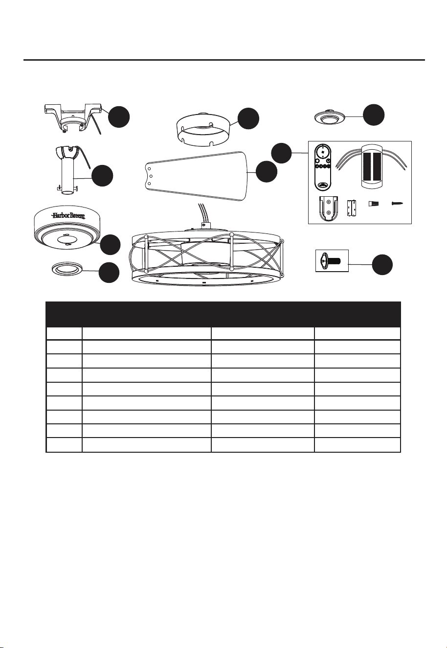
REPLACEMENT PART LIST
I
A
B
C
D
E
AA
H
F
DIM
R
X2
X6
For replacement parts, call our customer service department at 888-251-1003, 8 a.m.
–
8 p.m., EST,
Monday – Sunday. You could also contact us at [email protected].
A
B
C
D
E
F
H
I
AA
Mounting Bracket
Downrod Assembly
Canopy
Canopy Cover
Coupling Cover
Blade
Steel Cap
Remote Unit
Blade Screw
A102-0084184
A103-0328019
A101-0583019
A108-0013019
A106-0534019
A141-0736001
A183-0270019
A137-C055036
B166-1326005
YES
YES
YES
YES
YES
YES
YES
YES
YES
PART DESCRIPTION
COVERED UNDER
WARRANTY
PART#
18
ARTÍCULO #5249294
MODEL #HTE22023
Número de serie
Fecha de compra
VENTILADOR
YORKMONT
ADJUNTE SU RECIBO AQUÍ
HARBOR BREEZE y el diseño del
logotipo son marcas comerciales o
marcas registradas de LF, LLC.
Todos los derechos reservados.

19
ÍNDICE
Contenido del paquete........................................................................................................
Aditamentos........................................................................................................................
Información de seguridad....................................................................................................
Preparación .........................................................................................................................
Instrucciones de instalación iniciales ........................................................................................
Instrucciones estándar o de montaje en ángulo..................................................................
Instrucciones de cableado..................................................................................................
Instrucciones de instalación finales.....................................................................................
Instrucciones de funcionamiento........................................................................................
Cuidado y mantenimiento...................................................................................................
Solución de problemas .......................................................................................................
Garantía limitada de por vida .............................................................................................
Lista de piezas de repuesto ................................................................................................
20
21
21
22
23
24
26
27
28
30
31
33
Advertencia de la FCC........................................................................................................
34
35
20
CONTENIDO DEL PAQUETE
DESCRIPCIÓN CANTIDAD
L
I
J
K
M
N
1
1
1
1
1
2
2
A
B
C
D
E
F
G
1
1
1
1
1
3
1
H
Unidad de control remoto
Pasador de horquilla
(preensamblado en el ensamble
de la varilla [B])
Sujetador de horquilla
(preensamblado en el ensamble
de la varilla [B])
Acoplador(preensamblado en el
ensamble del motor [G])
Tornillo para el acoplador
(preensamblado en el acoplador [L])
Tornillo para soporte de montaje
(preensamblado en el soporte
de montaje [A])
Tapa de acero
Base
Cubierta de la base
Cubierta del acoplador
Soporte de montaje
Ensamble de la varilla
Ensamble del motor
Aspa
PIEZA DESCRIPCIÓN CANTIDADPIEZA
I
A
N
B
J
K
C
D
E
F
H
G
M
L
DIM
R
X2
X6
21
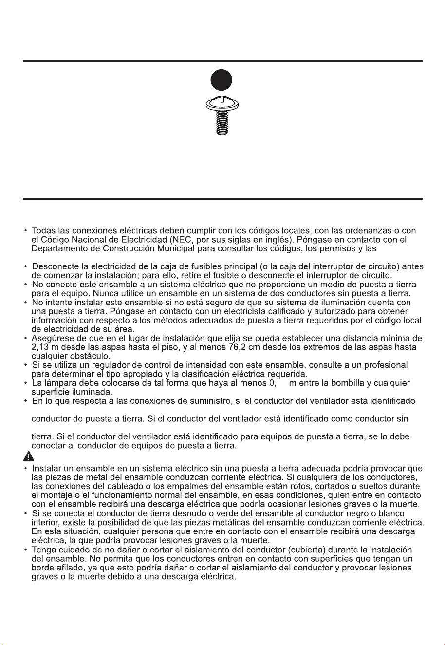
Cantidad: 9 +1 adicional
Tornillo para aspa
INFORMACIÓN DE SEGURIDAD
LEA Y GUARDE ESTAS INSTRUCCIONES
Lea y comprenda por completo este manual antes de intentar ensamblar, usar o instalar el producto.
inspecciones locales.
como conductor con puesta a tierra, se lo debe conectar a un suministro de electricidad con
puesta a tierra, se lo debe conectar a un suministro de electricidad con un conductor sin puesta a
PELIGRO
49
ADITAMENTOS (no se muestran en tamaño real)
AA
22
PRECAUCIÓN
ADVERTENCIA
PREPARACIÓN
Riesgo de incendio.
para 60 °C. Consulte a un electricista calificado antes de la instalación.
Tiempo estimado de ensamblaje:
15,87
aislante
23
INSTRUCCIONES DE INSTALACIÓN INICIALES
PELIGRO:
si no desconecta el suministro de la
A.
Montaje estándar:
B. Montaje en ángulo:
1.
Interrumpa el suministro de energía del ventilador apagando
los interruptores de circuito y el interruptor de pared.
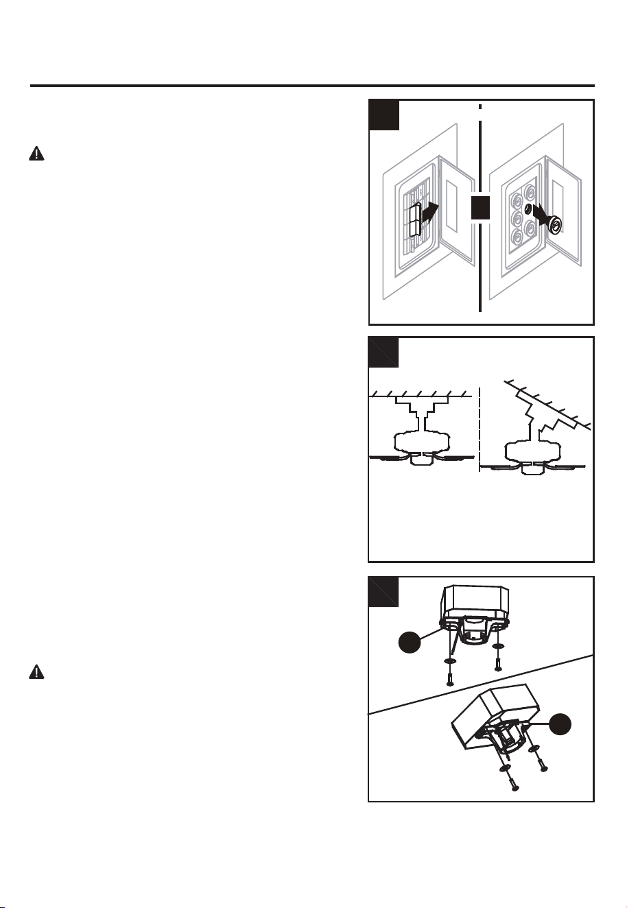
2. Elija el método de montaje deseado:
El montaje estándar es más adecuado para techos con
una altura de 2,43 m o superior. Para techos más altos,
se recomienda utilizar una varilla más larga (no incluida).
El montaje en ángulo es mejor para los techos en ángulo
o de bóveda. En ocasiones, es necesaria una varilla más
larga para asegurar una adecuada separación de las
aspas. Si realiza la instalación en ángulo, verifique que
el ángulo del techo no tenga una inclinación superior a
los 20°.
3.
Verifique la caja de salida existente (no incluida) para
asegurarse de que se encuentre firmemente sujetada a,
al menos, dos puntos de un miembro estructural del
techo y que pueda soportar el peso total del ventilador.
Una vez que la haya verificado, instale el soporte de
montaje (A) en la caja de salida con los tornillos y las
arandelas que se incluyen en la caja de salida.
instalación, pueden producirse lesiones graves o la
muerte.
PELIGRO:
una caja de salida suelta puede hacer que el
Nota:
si realiza el montaje en ángulo, asegúrese de
ventilador se tambalee y que aumenten las posibilidades de
que el extremo abierto del soporte de montaje (A) esté
instalado en dirección hacia el punto más alto del techo.
que el ventilador se caiga, lo que puede causar lesiones graves
o la muerte.
Para todas las opciones de montaje, es necesario que las
puntas de las aspas estén al menos a 76,2 cm de la pared
más cercana. Además, asegúrese de que haya al menos
2,13 metros desde el borde inferior del aspa hasta el piso.
A
B
2
3
Montaje
Estándar
A
Montaje en ángulo
A
O
1
Apague la fuente de alimentación
24
INSTRUCCIONES DE INSTALACIÓN INICIALES
4.
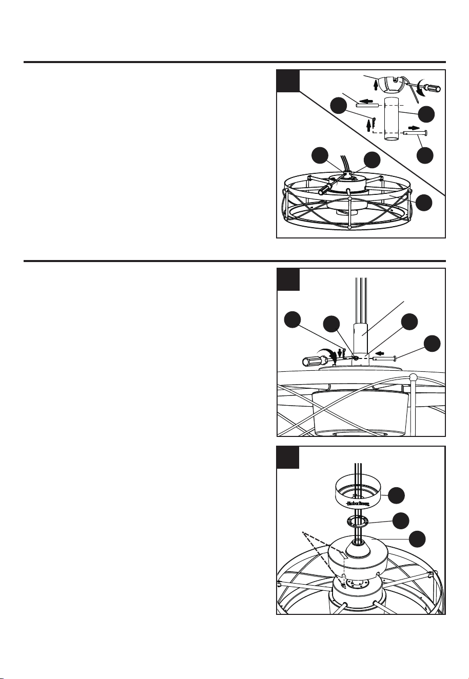
Retire el sujetador (K) y el pasador cruzado (J) ensamble
de la varilla (B). Afloje los tornillos para el acoplador (M)
en el acoplador (L).
Retire la parte de la bola de suspensión del conjunto de la
varilla descendente (B) aflojando el tornillo de fijación en
la bola de la percha hasta que la bola caiga libremente por
la varilla descendente. Retire el pasador de la varilla
descendente y, a continuación, retire la bola de
suspensión. Conserve el pasador y la bola de suspensión
para la reinstalación.
Nota: asegúrese de mantener los aditamentos sueltos
separados para evitar confundirlos durante la instalación.
INSTRUCCIONES ESTÁNDAR O DE MONTAJE EN ÁNGULO
1. Pase los conductores de fuerza del ensamble del motor
a través del
bola para colgar. Luego,inserte el bola
para colgar
en el acoplador (L) del ensamble del motor.
Alinee el orificio del
bola para colgar con el orificio del
acoplador (L) y luego vuelva a instalar el pasador de
horquilla (J). Vuelva a fijar el sujetador de horquilla (K)
en el pasador de horquilla (J) hasta que encaje en su
lugar. Luego, apriete los dos tornillos del acoplador (M)
que aflojó anteriormente.
2. Dirija los cables a través de la cubierta de acoplamiento
(E), la cubierta del dosel (D) y el dosel (C). Alinee el
orificio rectangular de la cubierta de acoplamiento (E)
con el interruptor inverso del conjunto del motor.
G
M
L
4
Bola colgante
J
B
K
Pasador
Debe alinearse
1
C
D
E
2
L
K
M
J
Varilla
25
PRECAUCIÓN:
asegúrese de que todos los tornillos
estén apretados antes de avanzar al siguiente paso.
INSTRUCCIONES ESTÁNDAR O DE MONTAJE EN ÁNGULO
4. Corte el excedente de conductores del ensamble a unos
15,24 cm a 22,86 cm aproximadamente por sobre la
parte superior del ensamble de la varilla (B). Pele 12,7
mm del aislamiento del extremo de cada conductor del
ensamble.
4
B
De 15,24 cm
a 22,86 cm
5. Levante cuidadosamente el ensamble y coloque la bola
de gancho del ensamble de la varilla (B) sobre el soporte
de montaje (A) que se encuentra fijado a la caja de
salida. Asegúrese de que la ranura de la bola de gancho
esté alineada con la lengüeta del soporte de montaje (A).
Esto permite tener las manos libres para conectar el
cableado.
Vaya al tema CABLEADO, en la página 26.
PELIGRO: tenga cuidado cuando alinee la lengüeta
con la muesca. Si no calza bien, es posible que el
ventilador se caiga, lo que podría provocar lesiones
graves o la muerte.
A
5
Bola
colgante
Ranura
Lengüeta
Sí
B
3.
3
Bola colgante
Pasador
Varilla
Vuelva a colocar la semiesfera en el barral como se
indica a continuación. Pase los cables de negro, blanco
y azul a través de la semiesfera. Pase el pasador a través
de los dos orificios en el barral y alinee la semiesfera de
modo que el pasador quede atrapado en la ranura de la
parte superior de la misma. Empuje la semiesfera hacia
arriba, bien ajustada contra el pasador. Ajuste firmemente
el tornillo de fijación en la semiesfera. Si el tornillo de
fijación está flojo, podría provocar oscilación del ventilador.
26
INSTRUCCIONES DE CABLEADO
ADVERTENCIA:
para evitar una posible descarga eléctrica, asegúrese de cortar la
alimentación eléctrica de la caja de fusibles principal antes de colgar el ventilador.
ADVERTENCIA: si no está seguro de si la caja de salida tiene puesta a tierra, póngase en
contacto con un electricista certificado para solicitar asesoramiento, ya que debe tener puesta a
tierra para un funcionamiento seguro.
1. Siga los pasos a continuación para cablear el ventilador.
Conecte el conductor BLANCO del ventilador al conductor
BLANCO marcado "TO MOTOR N" del receptor.
Conecte el conductor AZUL del ventilador al conductor
AZUL marcado "FOR LIGHT" del receptor.
Conecte el conductor NEGRO del ventilador al conductor
NEGRO marcado "AC IN L" del receptor.
Conecte el conductor NEGRO de la caja de salida al
conductor NEGRO marcado "AC IN L" del receptor.
Conecte el conductor BLANCO de la caja de salida al
conductor BLANCO marcado "AC IN N" del receptor.
Conecte el conductor DE PUESTA A TIERRA (VERDE)
de la abrazadera para colgar la bola de la varilla al
conductor DE PUESTA A TIERRA (VERDE o de COBRE
DESNUDO) de la casa.
ADVERTENCIA: si los conductores de la casa no tienen los mismos colores que se
mencionan en los siguientes pasos, deténgase de inmediato. Recomendamos que un electricista
profesional determine el cableado adecuado.
ADVERTENCIA: si considera que no tiene suficiente conocimiento o experiencia en cableados
eléctricos, es recomendable que un electricista autorizado instale el ventilador.
1
Caja de salida
Blanco
Blanco
Blanco
Negro
Verde
Verde
Azul
(FOR LIGHT)
Azul
(FOR LIGHT)
Negro
Negro
Receptor
Negro
Blanco
2
NEGRO
BLANCO
VERDE
Caja de salida
2. Coloque cinta aislante (no se incluye) alrededor de cada
conector de conductores y asegúrese de que no haya
conductores desnudos ni filamentos de conductores
visibles después de hacer las conexiones. Luego, gire
los conductores hacia arriba y, con cuidado, colóquelos
dentro de la caja de salida. Asegúrese de que las
conexiones BLANCAS y VERDES estén de un lado y
de que las conexiones NEGRAS estén del otro.
Aditamentos utilizados
Conector de conductores
x 6
INSTRUCCIONES DE CABLEADO
27
INSTRUCCIONES DE INSTALACIÓN FINALES
1. Afloje (pero no retire) los dos tornillos del soporte de
montaje (N) preensamblados en el soporte de
montaje (A) que se alinean con los orificios ranurados
en la base (C). Levante la base (C) para que los
orificios ranurados calcen con las cabezas de los
tornillos flojos en el soporte de montaje (A). Luego, gire
la base (C) en dirección de las manecillas del reloj,
apriete bien todos los tornillos.
2. Levante la cubierta de la base (D) sobre los tornillos del
soporte de montaje (N) visibles en la base (C). Gire la
cubierta de la base (D) en dirección de las manecillas
del reloj hasta fijarla en su lugar. Es posible que
necesite ajustar los tornillos del soporte de montaje (N)
hasta que la base (C) y su cubierta (D) estén ajustadas.
1
A
N
C
2
C
N
D
3
3.
Una vez que complete el paso de cableado, deslice el
receptor cableado entre el soporte de montaje (A) y la
parte superior del ensamble de la varilla (B) con el lado
plano del receptor apuntando hacia el techo.
A
Receptor
28
4 .
INSTRUCCIONES DE FUNCIONAMIENTO
1. Cuando cambie la estación, quizá desee cambiar la
dirección en la que gira su ventilador.
En climas más cálidos, la rotación en dirección contraria
a las manecillas del reloj crea un flujo de aire
descendente que enfría el aire. Presione el interruptor
hacia la IZQUIERDA y verá un icono de SOL.
En climas más fríos, la rotación en dirección de las
manecillas del reloj crea un flujo de aire ascendente,
que mueve el aire caliente del techo. Presione el
interruptor hacia la DERECHA y verá un icono de
COPO DE NIEVE.
ADVERTENCIA: apague y espere a que el
ventilador se detenga antes de colocar el interruptor de
reversa.
Nota: si tiene dificultades para hacerlo manualmente,
use un destornillador o un bolígrafo pequeño para
mover el interruptor de reversa.
Coloque la tapa de acero (H) en el eje del motor y
gírela hasta que quede en su lugar.
Nota: no apriete demasiado la tapa de acero (H).
H
4
1
INSTRUCCIONES DE INSTALACIÓN FINALES
3.
Aditamentos utilizados
Tornillo para aspa x 9
AA
Deslice las aspas (F) a través de las ranuras del
volante y fíjelas al eje del motor con los tornillos de las
aspas (AA). Asegúrese de que los tornillos que sujetan
las aspas (F) al eje del motor estén apretados y
asentados correctamente.
Nota: revise periódicamente los aditamentos de las
aspas y vuelva a asegurarlos si es necesario.
F
3
AA
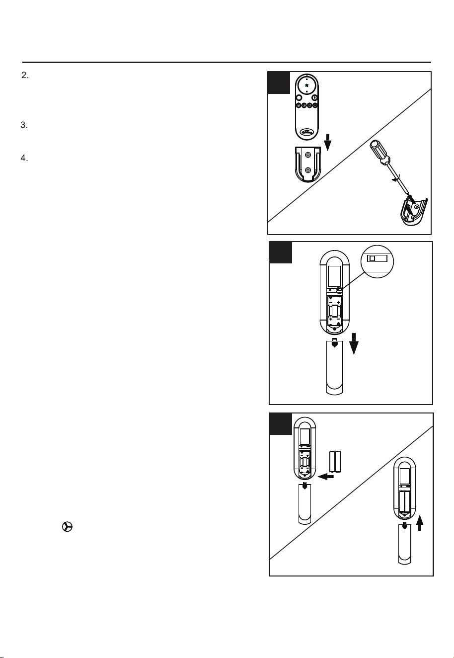
29
• Cuando su control remoto no responde (asegúrese de
que la batería no esté descargada)
• Después de haber reemplazado un transmisor o
receptor defectuoso por uno nuevo.
Después de instalar y cablear la unidad, restablezca la
alimentación de su ventilador, mantenga presionado el
botón “ ” del transmisor durante 5 segundos hasta
que el ventilador emita un pitido para indicar que se ha
completado el proceso de aprendizaje del código. Esta
operación debe completarse dentro de 1 minuto
después de restaurar la alimentación del ventilador.
3
2
4
NOTA: cada transmisor de este control remoto lleva un
código de identificación único para facilitar la
comunicación entre dispositivos vinculados. El código de
identificación se establece en la fábrica y no lo puede
cambiar el usuario. Sin embargo, se le pedirá que realice
un proceso de "aprendizaje de código de identificación"
manualmente en estas circunstancias:
NOTA:
este control remoto utiliza dos baterías AAA de
1.5 voltios. Reemplace las baterías por otras del tamaño
y el tipo correcto. Limpie los contactos de la batería y el
área interior del dispositivo antes de instalar las baterías
nuevas. Asegúrese de que las baterías estén instaladas
de manera correcta en lo que se refiere a la
polaridad (+ y -).
• Si tiene varios ventiladores instalados cerca y desea
controlar todos los ventiladores con un mismo transmisor
remoto.
Deslice el transmisor fuera del soporte. Seleccione una
ubicación para instalar su soporte. Fije el soporte con
los tornillos proporcionados.
retire las baterías si el control remoto no se ha
utilizado durante un período largo con el fin de evitar
daños. Almacene el control remoto alejado del calor y
humedad extremos.
INSTRUCCIONES DE FUNCIONAMIENTO
NOTA:
cada ventilador requiere su propio receptor.
NOTA:
Para que el ventilador funcione, instale dos baterías
AAA de 1.5 voltios (se incluye). Vuelva a colocar la
cubierta de las baterías.
Abra la cubierta de las baterías.
DIM
R
ON
DIM
ON
A
UM-4 1.5VX2
A
A
A
A
A
FCC ID:M8C-EEC118RF433
DIM
This device complies with part 15 of the
FCC Rules. Operation is subject to the
following two conditions: (1)This device
may not cause harmful interference,
and (2)this device must accept any
Interference that may cause undesired
operation
A
UM-4 1.5VX2
A
-
+
AAA
A
A
A
A
-
+
A AA
DIM
ON
FCC ID:M8C-EEC118RF433
This device complies with part 15 of the
FCC Rules. Operation is subject to the
following two conditions: (1)This device
may not cause harmful interference,
and (2)this device must accept any
Interference that may cause undesired
operation
DIM
ON
FCC ID:M8C-EEC118RF433
This device complies with part 15 of the
FCC Rules. Operation is subject to the
following two conditions: (1)This device
may not cause harmful interference,
and (2)this device must accept any
Interference that may cause undesired
operation
30
CUIDADO Y MANTENIMIENTO
IMPORTANTE: antes de realizar cualquier trabajo de mantenimiento, desconecte el suministro
de electricidad principal. No utilice agua ni un paño húmedo para limpiar el ventilador de techo.
Al menos dos veces por año, apriete todos los tornillos y baje la base para inspeccionar los
tornillos de la placa de montaje.
Limpie el ventilador solo con un cepillo suave o un paño sin pelusas para evitar rayar el acabado.
Limpie las aspas con un paño sin pelusas. De vez en cuando puede aplicar una fina capa de cera
para muebles en las aspas de madera para darles más protección.
INSTRUCCIONES DE FUNCIONAMIENTO
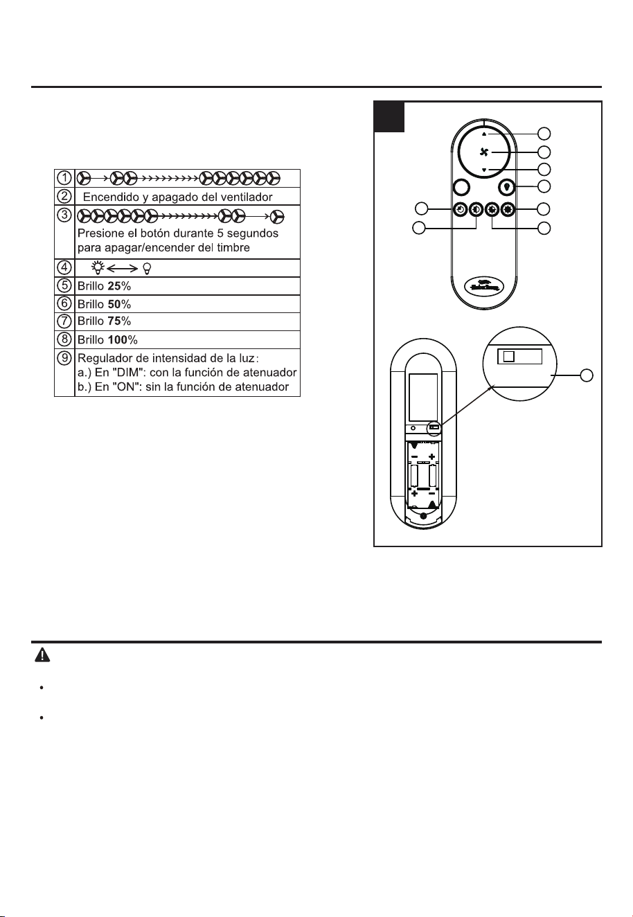
5. Los botones en el control remoto del kit de
alimentación controlan la velocidad y la luz del
ventilador como se indica a continuación:
NOTA:
NOTA:
el ajuste de fábrica está en la posición " DIM ".
este receptor tiene una función de memoria
preestablecida. Cuando se APAGA el interruptor, el
control remoto recordará la intensidad de la luz y la
velocidad del ventilador. Cuando se ENCIENDE
nuevamente el interruptor, la luz y el ventilador
reanudarán su funcionamiento del mismo modo en
el que lo hacía antes de APAGARLO.
5
ON
DIM
ON
A
UM-4 1.5VX2
A
A
A
A
A
FCC ID:M8C-EEC118RF433
DIM
9
This device complies with part 15 of the
FCC Rules. Operation is subject to the
following two conditions: (1)This device
may not cause harmful interference,
and (2)this device must accept any
Interference that may cause undesired
operation
DIM
1
2
3
4
7
8
5
6
R
31
SOLUCIÓN DE PROBLEMAS
3. Ruido normal. 3. Permita un período de “asentamiento” de 24
horas. La mayoría de los ruidos asociados
con un ventilador nuevo desaparecerán
después de este período.
1.
La abrazadera para colgar o
la caja de salida del techo no
están bien fijadas.
1.
Fije los tornillos de la abrazadera para colgar a
la caja de salida o asegure la caja de salida.
2.
El tornillo de fijación del
ensamble de la varilla está
suelto.
2.
Apriete el tornillo de fijación del ensamble de la
varilla.
3.
La bola de gancho del
ventilador no está
correctamente asentada en
las lengüetas de la base.
3.
Corte el suministro de alimentación, sujete el
ventilador con cuidado y verifique que la bola
para colgar esté instalada correctamente.
4. El tornillo de fijación del
acoplador del motor está
suelto.
4.
Levante el acoplador del motor y apriete
bien los tornillos de fijación.
5. El aspa está suelta.
5.
Compruebe que todas las aspas estén
firmemente atornilladas en los soportes de
las aspas.
6. Los soportes de las aspas
están sueltos.
6.
Compruebe que los soportes de hierro del
aspa del ventilador estén bien y
uniformemente asentados en la superficie
del motor. Si los rebordes no están bien
asentados, afloje los tornillos para los
rebordes y vuelva a apretarlos.
4.
Los conectores de cables de
la carcasa del interruptor
repiquetean.
4.
Compruebe que los conectores de cable de
la carcasa del interruptor no repiqueteen
unos contra otros o contra las paredes
interiores de la carcasa del interruptor.
5.
Hay un aspa partida.
5.
Reemplace las aspas.
6.
La distancia de la base al
techo es demasiado grande.
6.
Asegúrese de que la base superior esté a
una distancia corta del techo. No debería
tocar el techo.
7.
El vidrio no está asegurado.
7.
Asegure el vidrio.
El ventilador
emite mucho
ruido.
El ventilador
se tambalea.
PROBLEMA CAUSA POSIBLE
ACCIÓN CORRECTIVA
1. Los tornillos de fijación están
sueltos.
2. Se está usando un control de
velocidad no aprobado.
1. Apriete todos los tornillos de fijación.
2. Algunos motores de ventilador son sensibles
a las señales de los controles de velocidad
variable de estado sólido. NO USE un control
de velocidad variable de estado sólido.
32
SOLUCIÓN DE PROBLEMAS
9. Cambie a una velocidad
diferente.
9. Cuando cambie de velocidad media a baja,
puede notar que el ventilador tambalea un
poco. Cuando el ventilador se estabilice a
velocidad baja, el tambaleo debería
desaparecer.
10. El ventilador no está bien
colocado.
10. Asegúrese de que la base y el soporte de
montaje estén bien apretados a la vigueta
del techo.
1. El ventilador está apagado, se
quemó un fusible o el
interruptor de circuito se
desconectó.
1. Conecte el suministro de electricidad,
reemplace el fusible o reinicie el interruptor
de circuito.
2. Las conexiones de cableado
están sueltas o son incorrectas.
2a. Corte el suministro de electricidad y afloje
la base. Revise todas las conexiones
según la sección INSTRUCCIONES DE
CABLEADO en la página 26.
2b. Revise la conexión del enchufe en la
carcasa del interruptor.
3. El interruptor de reversa del
motor no está activado.
3. Mueva firmemente el interruptor hacia la
derecha o hacia la izquierda. El ventilador
no funciona cuando el interruptor está en el
centro.
El ventilador
se tambalea.
El ventilador
no arranca.
PROBLEMA CAUSA POSIBLE
ACCIÓN CORRECTIVA
7.
Las aspas están
desequilibradas.
8. El ventilador está demasiado
cerca del techo de bóveda.
7.
Intercambie dos aspas adyacentes; esto
redistribuirá el peso y podría hacer que
funcione más suavemente.
8.
Baje o mueva el ventilador. Puede pedir
varillas de extensión.

33
GARANTÍA LIMITADA DE POR VIDA
El fabricante garantiza que este ventilador no presenta defectos en los materiales ni en la mano de
obra presentes en el momento del transporte desde la fábrica, por un período de por vida (con
limitaciones) a partir de la fecha de compra. Esta garantía es válida solo para el comprador original.
El fabricante acepta reparar dichos defectos sin cargo o, según nuestro criterio, reemplazar el
ventilador de techo por un modelo comparable o superior.
Para obtener el servicio de garantía, presente una copia del recibo de venta como comprobante de la
compra. Todos los costos de extracción y reinstalación son responsabilidad explícita del comprador.
Cualquier daño al ventilador de techo producido por accidente, uso indebido o instalación incorrecta,
o a causa de accesorios de fijación, que no esté cubierto por esta garantía, será responsabilidad del
comprador. El fabricante no asume ningún tipo de responsabilidad por la instalación del ventilador
durante la garantía limitada de por vida. Cualquier servicio realizado por una persona no autorizada
invalidará la garantía.
Debido a las cambiantes condiciones climáticas, esta garantía no cubre cambios en el acabado de
latón, óxido, picaduras, deslustre, corrosión o descascarado. Los ventiladores con acabado mantienen
su belleza cuando se los protege de las condiciones climáticas cambiantes.
Cualquier reemplazo de piezas defectuosas para el ventilador de techo debe informarse dentro del
primer año a partir de la fecha de compra. Para conocer el saldo de la garantía, llame a nuestro
Departamento de Servicio al Cliente al 888-251-1003 para obtener la autorización para la
devolución y las instrucciones de envío, de modo que podamos reparar o reemplazar el ventilador de
techo. Cualquier ventilador o pieza devueltos con un embalaje incorrecto son responsabilidad única
del comprador. No existe otro tipo de garantía explícita. El fabricante rechaza cualquiera y todas las
garantías implícitas.
La duración de cualquier garantía implícita que no pueda rechazarse se limita al período limitado de
por vida especificado en nuestra garantía. El fabricante no será responsable por daños incidentales,
resultantes o especiales que surjan en relación con el uso o el funcionamiento del producto, excepto
que la ley indique lo contrario. Esta garantía le otorga derechos legales específicos, y usted tiene
también otros derechos que varían según el estado. Esta garantía sustituye cualquier garantía previa.
Nota: una pequeña cantidad de "tambaleo" es normal y no se debe considerar como un defecto.

34
ADVERTENCIA DE LA FCC
Este dispositivo (incluye control remoto y módulo LED) cumple con la sección 15 de las reglas de la
FCC. El funcionamiento está sujeto a las siguientes dos condiciones:
(1) Este dispositivo no debe causar interferencia perjudicial y (2) deberá aceptar cualquier
interferencia recibida, incluida la interferencia que pudiese causar la operación no deseada. Tenga
presente que cualquier cambio o modificación que no esté expresamente aprobado por la parte
responsable del cumplimiento podría anular la autorización del usuario para utilizar el equipo.
NOTA: tanto el control remoto como el módulo LED han sido probados y se ha verificado que cumplen
con los límites para un dispositivo digital Clase B, conforme a la parte 15 de las reglas de la FCC.
Estos límites están diseñados para proporcionar protección razonable contra interferencia perjudicial
El control remoto genera, usa y puede irradiar energía de radiofrecuencia y, si no se instala y usa de
en una instalación residencial.
acuerdo con las instrucciones, puede causar interferencia perjudicial a la recepción de radio o
televisión, lo que se puede determinar al apagar y encender el equipo. Se recomienda al usuario que
intente corregir la interferencia con una o más de las siguientes medidas:
- Reorientar o reubicar la antena de recepción.
- Aumentar la separación entre el equipo y el receptor.
- Conectar el equipo a un tomacorriente de un circuito distinto al que usa el receptor.
Solicite ayuda al distribuidor o a un técnico con experiencia en radio/TV.
35
Impreso en China
LISTA DE PIEZAS DE REPUESTO
Para obtener piezas de repuesto, llame a nuestro Departamento de Servicio al Cliente al 888-251-1003,
de lunes a domingo de 8 a.m. a 8 p.m., hora estándar del Este. También puede ponerse en contacto
I
A
B
C
D
E
AA
H
F
DIM
R
X2
X6
A
B
C
D
E
F
H
I
AA
Soporte de montaje
Ensamble de la varilla
Base
Cubierta de la base
Cubierta del acoplador
Aspa
Tapa de acero
Unidad de control remoto
Tornillo para aspa
A102-0084184
A103-0328019
A101-0583019
A108-0013019
A106-0534019
A141-0736001
A183-0270019
A137-C055036
B166-1326005
SÍ
SÍ
SÍ
SÍ
SÍ
SÍ
SÍ
SÍ
SÍ
PIEZA
CUBIERTO POR
LA GARANTÍA
DESCRIPCIÓN
PIEZA#