1
Instruction Manual
100276483_2000538796
KEEP THIS MANUAL IN THE POCKET ON HEATER FOR FUTURE REFERENCE
WHENEVER MAINTENANCE ADJUSTMENT OR SERVICE IS REQUIRED.
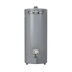
COMMERCIAL GAS WATER HEATERS
INSTALLATION - OPERATION -
SERVICE - MAINTENANCE
PLACE THESE INSTRUCTIONS ADJACENT TO HEATER AND NOTIFY OWNER TO KEEP FOR FUTURE REFERENCE.
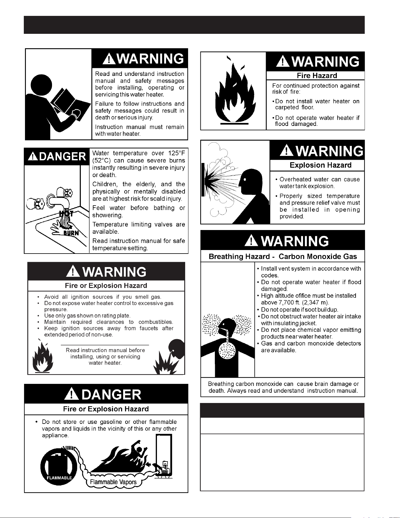
Read and understand this instruction
manual and the safety messages
herein before installing, operating or
servicing this water heater.
Failure to follow these instructions and
safety messages could result in death
or serious injury.
This manual must remain with the
water heater.
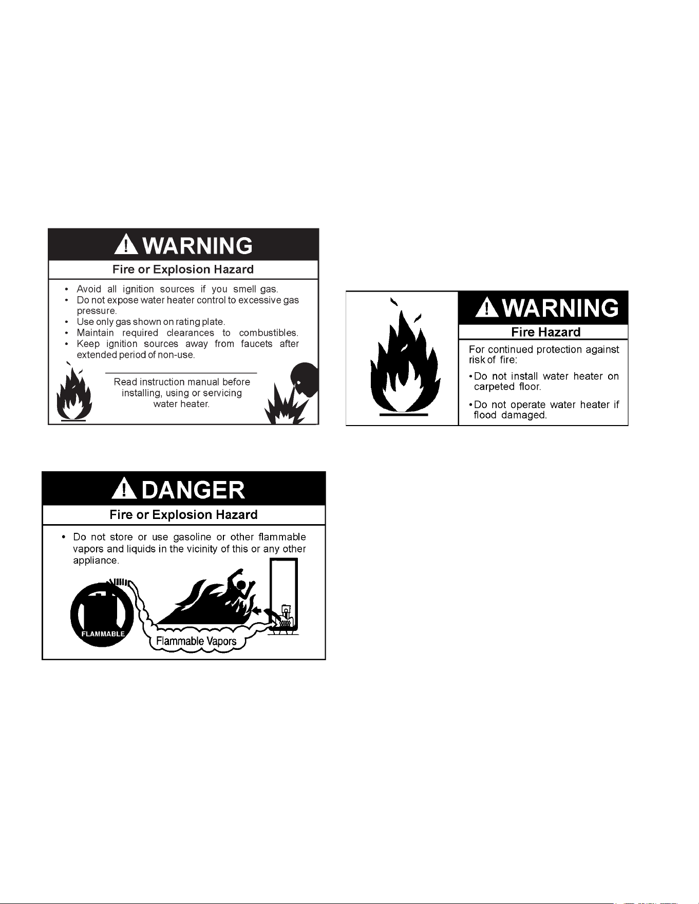
WARNING: If the information in these
instructions is not followed exactly, a fire
or explosion may result causing property
damage, personal injury or death.
Do not store or use gasoline or other
flammable vapors and liquids in the
vicinity of this or any other appliance.
WHAT TO DO IF YOU SMELL GAS:
Do not try to light any appliance.
Do not touch any electrical switch; do
not use any phone in your building.
Immediately call your gas supplier
from a neighbor’s phone. Follow the
gas supplier’s instructions.
If you cannot reach your gas supplier,
call the fire department.
Installation and service must be
performed by a qualified installer,
service agency or the gas supplier.
•
•
•
•
Low Lead Content
• For Your Safety •
AN ODORANT IS ADDED TO THE GAS USED
BY THIS WATER HEATER.

2
TABLE OF CONTENTS
SAFE INSTALLATION, USE AND SERVICE..................3
APPROVALS ..................................................................3
GENERAL SAFETY INFORMATION ..............................4
INTRODUCTION ............................................................5
Abbreviations Used ................................................... 5
Qualied Installer or Service Agency ......................... 5
Preparing for The Installation .................................... 5
INSTALLATION CONSIDERATIONS .............................6
Rough-In Dimensions ................................................ 6
Thermometers (Not Supplied) ................................... 7
Facts to Consider About the Location ........................ 7
High Altitude .............................................................. 9
Adjusting Air Shutter for Higher Altitudes ................... 9
Clearances ............................................................... 10
Insulation Blankets ................................................... 10
Hard Water ............................................................... 11
Circulation Pumps .................................................... 11
INSTALLATION REQUIREMENTS ..............................12
Gas Supply Systems ................................................ 12
Gas Pressure Requirements ................................... 12
Supply Gas Regulator .............................................. 12
Mixing Valves ............................................................ 12
Water Piping ............................................................. 13
Temperature-Pressure Relief Valve .......................... 14
Filling the Water Heater ............................................ 15
Air Requirements ...................................................... 16
Unconned Space .................................................... 16
Conned Space ........................................................ 16
Fresh Air Openings For Conned Spaces ................ 17
Outdoor Air Through Two Openings ......................... 17
Outdoor Air Through One Opening ........................... 17
Outdoor Air Through Two Horizontal Ducts .............. 18
Outdoor Air Through Two Vertical Ducts ................... 18
Air From Other Indoor Spaces .................................. 18
Venting ...................................................................... 19
Gas Piping ................................................................ 20
Sediment Traps ........................................................ 22
TEMPERATURE REGULATION ..................................24
FOR YOUR INFORMATION .........................................25
Start-UP CONDITIONS ............................................ 25
Operational Conditions ............................................. 26
PERIODIC MAINTENANCE .........................................27
Venting System Inspection ....................................... 27
Burner Inspection ..................................................... 27
Burner Cleaning ........................................................ 27
Air Shutter Adjustment .............................................. 28
Housekeeping ........................................................... 28
Anode Rod Inspection .............................................. 28
Temperature-Pressure Relief Valve Test .................. 28
Periodic Removal of Lime Deposits From Tank Type
Commercial Water Heaters ...................................... 30
Deliming Solvents ..................................................... 30
Tank Cleanout Procedure ......................................... 30
Deliming Using Flo-Jug Method ............................... 31
Draining and Flushing ............................................... 32
Service ...................................................................... 32
LEAKAGE TEST POINTS ............................................33
Removing and Replacing the Gas Control Valve/
Thermostat .............................................................. 34
WATER PIPING DIAGRAMS ........................................39
COMMERCIAL WATER HEATER LIMITED
WARRANTY .................................................................46
3
SAFE INSTALLATION, USE AND SERVICE
The proper installation, use and servicing of this water heater is extremely important to your safety and the safety of
others.
Many safety-related messages and instructions have been provided in this manual and on your own water heater to
warn you and others of a potential injury hazard. Read and obey all safety messages and instructions throughout this
manual. It is very important that the meaning of each safety message is understood by you and others who install,
use, or service this water heater.
All safety messages will generally tell you about the type of hazard, what can happen if you do not follow the safety
message, and how to avoid the risk of injury.
DANGER indicates an imminently
hazardous situation which, if not avoided,
will result in injury or death.
This is the safety alert symbol. It is used to alert you to
potential personal injury hazards. Obey all safety
messages that follow this symbol to avoid possible
injury or death.
WARNING indicates a potentially hazardous
situation which, if not avoided, could result
in injury or death.
CAUTION indicates a potentially hazardous
situation which, if not avoided, could result in
minor or moderate injury.
CAUTION used without the safety alert
symbol indicates a potentially hazardous
situation which, if not avoided, could result in
property damage.
WARNING
CAUTION
CAUTION
DANGER
APPROVALS
Low Lead Content
4
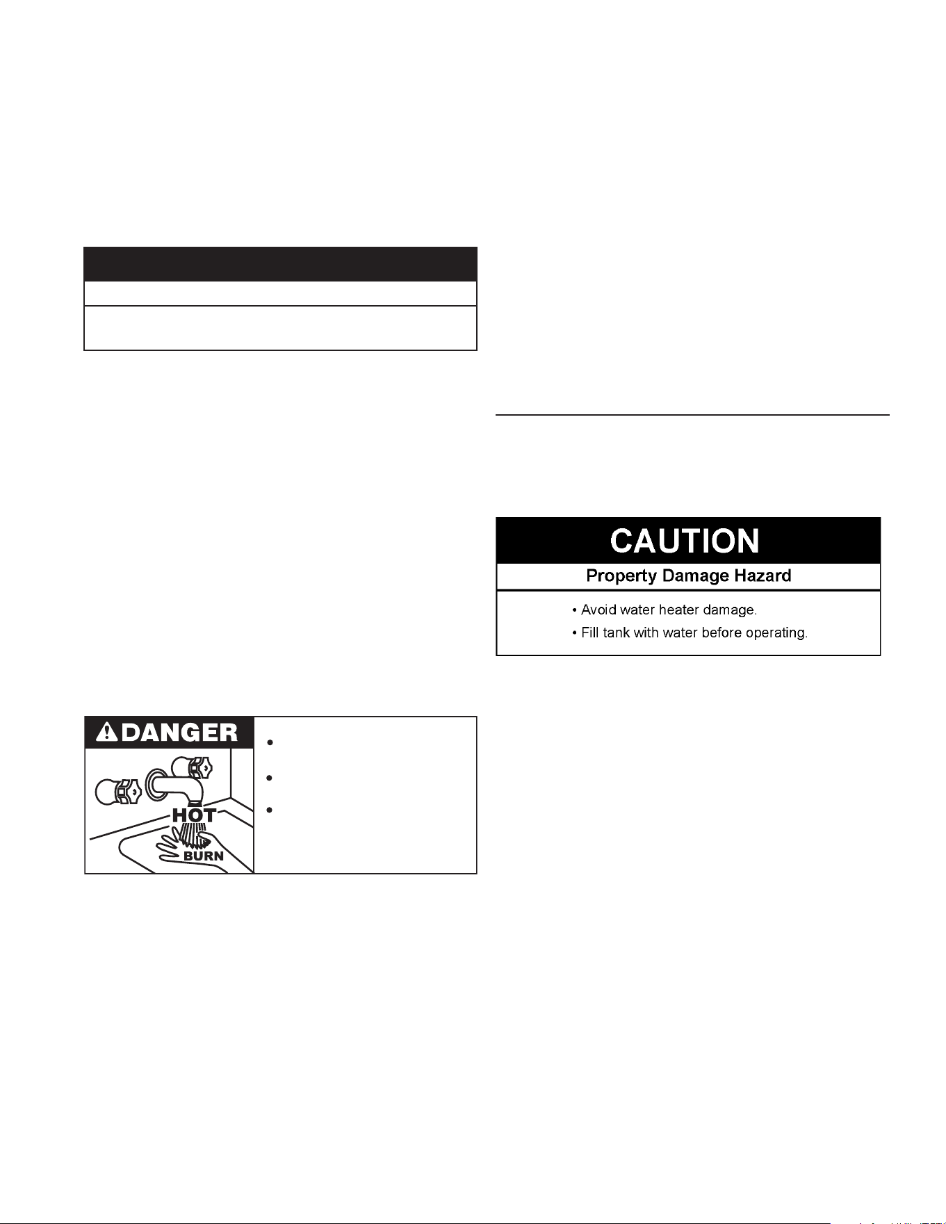
GENERAL SAFETY INFORMATION
Improper installation, use and service may
result in property damage.
CAUTION
•
Do not operate water heater if any part has been
exposed to flooding or water damage.
•
Inspect anode rods regularly, replace when significantly depleted.
•
Install in location with drainage.
•
Fill tank with water before operation.
•
Properly sized thermal expansion tanks are required on all
closed water systems.
Refer to this manual for installation and service.

5
Thank You for purchasing this water heater. Properly
installed and maintained, it should give you years of
trouble free service.
ABBREVIATIONS USED
Abbreviations Found In This Instruction Manual:
• UL - Underwriters Laboratories Inc.
• ANSI - American National Standards Institute
• NFPA - National Fire Protection Association
• ASME - American Society of Mechanical Engineers
• AHRI - Air-Conditioning, Heating and Refrigeration
Institute
• CAN - Canada
• EPACT - Energy Policy Act
• CSA - Canadian Standards Association
This gas-red water heater is design certied by
Underwriters Laboratories Inc. under the American
National Standard/CSA Standard for Gas Water Heaters
ANSI Z21.10.3 • CSA 4.3 (current edition).
QUALIFIED INSTALLER OR SERVICE AGENCY
Installation and service of this water heater requires
ability equivalent to that of a Qualied Agency (as dened
by ANSI below) in the eld involved. Installation skills
such as plumbing, air supply, venting, gas supply and
electrical supply are required in addition to electrical
testing skills when performing service.
ANSI Z223.1 2006 Sec. 3.3.83: “Qualied Agency” - “Any
individual, rm, corporation or company that either in
person or through a representative is engaged in and is
responsible for (a) the installation, testing or replacement
of gas piping or (b) the connection, installation, testing,
repair or servicing of appliances and equipment; that
is experienced in such work; that is familiar with all
precautions required; and that has complied with all the
requirements of the authority having jurisdiction.”
If you are not qualied (as dened by ANSI above) and
licensed or certied as required by the authority having
jurisdiction to perform a given task do not attempt to
perform any of the procedures described in this manual.
If you do not understand the instructions given in this
manual do not attempt to perform any procedures
outlined in this manual.
PREPARING FOR THE INSTALLATION
1. Read the “General Safety” section, page 4 of this
manual rst and then the entire manual carefully. If you
don’t follow the safety rules, the water heater will not
operate properly. It could cause DEATH, SERIOUS
BODILY INJURY AND/OR PROPERTY DAMAGE.
This manual contains instructions for the installation,
operation, and maintenance of the gas-red water
heater. It also contains warnings throughout the manual
that you must read and be aware of. All warnings and
all instructions are essential to the proper operation of
the water heater and your safety. Since we cannot put
everything on the rst few pages, READ THE ENTIRE
MANUAL BEFORE ATTEMPTING TO INSTALL OR
OPERATE THE WATER HEATER.
2. The installation must conform with these instructions
and the local code authority having jurisdiction. In the
absence of local codes, the installation must comply
with the current editions of the National Fuel Gas Code,
ANSI Z223.1/NFPA 54 or CAN/CSA-B149.1 the Natural
Gas and Propane Installation Code. All documents are
available from the Canadian Standards Association,
8501 East Pleasant Valley Road, Cleveland, OH
44131. NFPA documents are also available from the
National Fire Protection Association, 1 Batterymarch
Park, Quincy, MA 02269.
3. If after reading this manual you have any questions or
do not understand any portion of the instructions, call
the local gas utility or the manufacturer whose name
appears on the rating plate.
4. Carefully plan the place where you are going to put
the water heater. Correct combustion, vent action, and
vent pipe installation are very important in preventing
death from possible carbon monoxide poisoning and
res, see Figure 8 (page 10) and Figure 12 (page
14).
Examine the location to ensure the water heater is
consistent with the requirements described in Facts to
Consider About the Location (page 7).
5. For California installation this water heater must be
braced, anchored, or strapped to avoid falling or
moving during an earthquake. See instructions for
correct installation procedures. Instructions may be
obtained from California Ofce of the State Architect,
400 P Street, Sacramento, CA 95814.
6. Massachusetts Code requires this water heater to be
installed in accordance with Massachusetts 248-CMR
2.00: State Plumbing Code, and 248-CMR 5.00.
INTRODUCTION
6
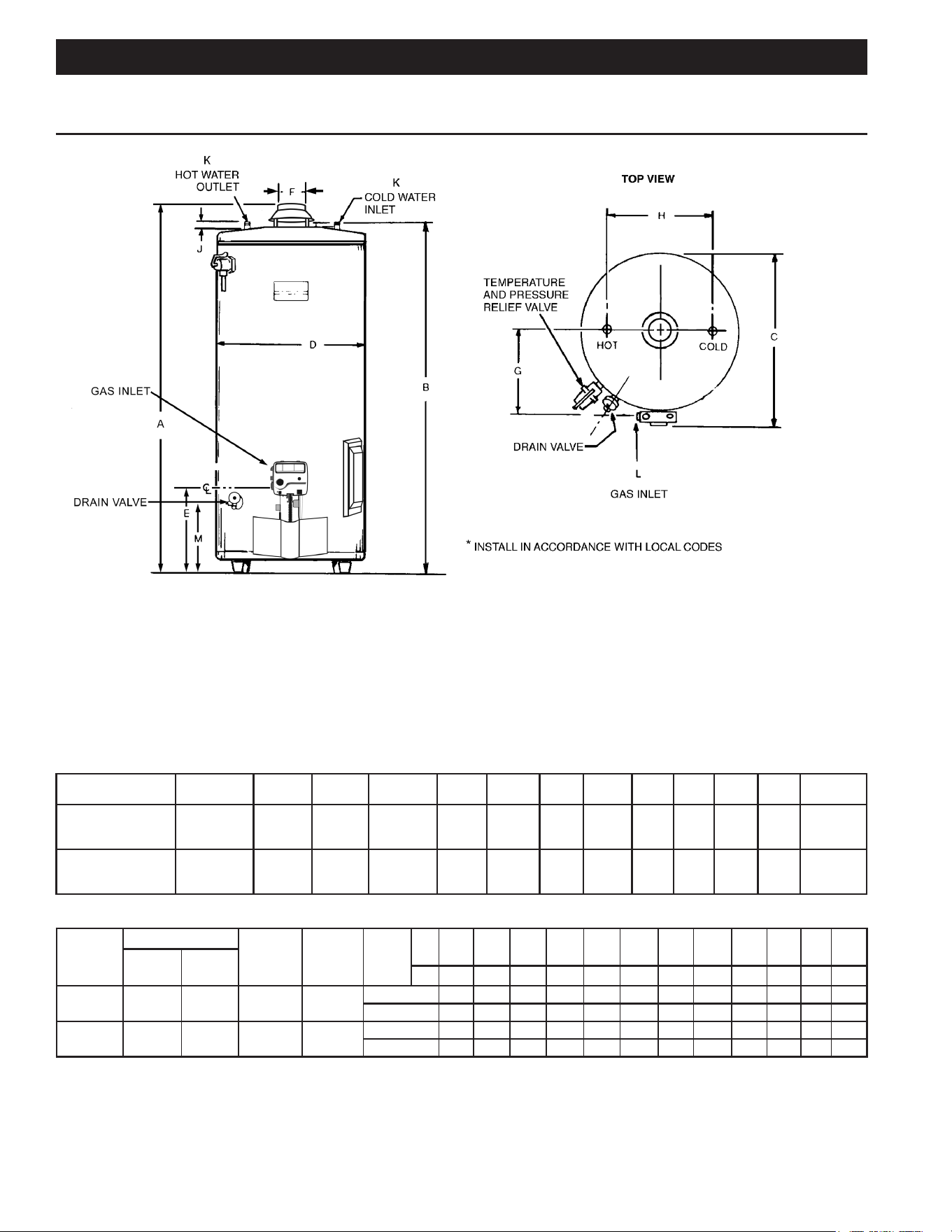
ROUGH-IN DIMENSIONS
TABLE 1. DIMENSIONS AND RECOVERY RATINGS DIMENSIONS
Model Units A B C D E F G H J K L M
75
Natural & LP
Inches
CM
61 7/8
157.2
59 3/8
150.8
29 15/16
76
26 1/2
67.3
14 3/16
36
4
10.2
14 7/8
39.4
16
40.6
1 7/8
4.8
1
NPT
1/2
NPT
12.0
30.5
100
Natural & LP
Inches
CM
69 7/8
177.5
67 3/8
171.1
31 1/2
80.0
27 3/4
70.5
14 1/8
35.9
4
10.2
15 5/8
39.7
16
40.6
1 7/8
4.8
1 1/4
NPT
1/2
NPT
11 15/16
30.3
TABLE 2. RECOVERY RATINGS
Model
Input
Approx.
Gal.
Cap.
Approx.
Liter
Cap.
Temp.
Rise
C° 17 22 28 33 39 44 50 56 61 67 72 78
Rating
Btu/Hr
Rating
kW
F° 30 40 50 60 70 80 90 100 110 120 130 140
75 75,100 22 74 280
GPH 243 182 146 121 104 91 81 73 66 61 56 52
LPH 916 686 550 456 392 343 305 275 249 230 211 196
100 75,100 22 98 371
GPH 243 182 146 121 104 91 81 73 66 61 56 52
LPH 916 686 550 456 392 343 305 275 249 230 211 196
Recovery ratings based on 80% thermal efciency.
INSTALLATION CONSIDERATIONS
FIGURE 1. ROUGH-IN DIMENSIONS
7
THERMOMETERS (NOT SUPPLIED)
Thermometers should be obtained and eld installed.
Thermometers are installed in the system as a means of
detecting the temperature of the outlet water supply.
This Water Heater has been design certied as
complying with ANSI Z21.10.3-CSA 4.3 current edition for
water heaters and is considered suitable for:
• Water (Potable) Heating and Space Heating*: All
models are considered suitable for water (potable)
heating and space heating.
*These water heaters cannot be used in space heating
applications only.
HOTTER WATER CAN SCALD:
Water heaters are intended to produce hot water.
Water heated to a temperature which will satisfy space
heating, clothes washing, dish washing, and other
sanitizing needs can scald and permanently injure
you upon contact. Some people are more likely to be
permanently injured by hot water than others. These
include the elderly, children, the inrm, or physically/
mentally handicapped. If anyone using hot water in your
home ts into one of these groups or if there is a local
code requiring a certain temperature water at the hot
water tap, then you must take special precautions. In
addition to using the lowest possible temperature setting
that satises your hot water needs, a means such as a
*Mixing Valve should be used at the hot water taps used
by these people or at the water heater. See Figure 11
(page 13). Mixing valves are available at plumbing
supply or hardware stores. Consult a qualied installer
or service agency. Follow mixing valve manufacturer’s
instructions for installation of valves. Before changing
the factory setting on the thermostat, see Temperature
Regulation (page 24).
FACTS TO CONSIDER ABOUT THE LOCATION
Carefully choose an indoor location for the new water
heater, because the placement is a very important
consideration for the safety of the occupants in the
building and for the most economical use of the water
heater. This water heater is not for use in manufactured
(mobile) homes or outdoor installation.
Whether replacing an old water heater or putting the
water heater in a new location, the following critical points
must be observed:
1. Select a location indoors as close as practical to the
gas vent or chimney to which the water heater vent
is going to be connected, and as centralized with the
water piping system as possible.
2. Selected location must provide adequate clearances
for servicing and proper operation of the water heater.
Installation of water heater must be accomplished in
such a manner that if the tank or any connections should
leak, ow will not cause damage to the structure. For
this reason, it is not advisable to install water heater in
an attic or upper oor. When such locations cannot be
avoided, a suitable metal drain pan should be installed
under the water heater. Metal Drain pans are available
at your local hardware store. Such a metal drain pan
must have a minimum length and width of at least 2” (51
mm) greater than water heater dimensions and must be
piped to an adequate drain. The pan must not restrict
combustion air ow.
Water heater life depends upon water quality, water
pressure and the environment in which the water heater
is installed. Water heaters are sometimes installed in
locations where leakage may result in property damage,
even with the use of a drain pan piped to a drain.
However, unanticipated damage can be reduced or
prevented by a leak detector or water shut-off device
used in conjunction with a piped drain pan. These
devices are available from some plumbing supply
wholesalers and retailers, and detect and react to
leakage in various ways:
8
• Sensors mounted in the drain pan that trigger an
alarm or turn off the incoming water to the water
heater when leakage is detected.
• Sensors mounted in the drain pan that turn off the
water supply to the entire home when water is
detected in the drain pan.
• Water supply shut-off devices that activate based on
the water pressure differential between the cold water
and hot water pipes connected to the water heater.
• Devices that will turn off the gas supply to a gas water
heater while at the same time shutting off its water
supply.
INSTALLATIONS IN AREAS WHERE FLAMMABLE
LIQUIDS (VAPORS) ARE LIKELY TO BE PRESENT OR
STORED (GARAGES, STORAGE AND UTILITY AREAS,
ETC.): Flammable liquids (such as gasoline, solvents,
propane [LP or butane, etc.] and other substances such
as adhesives, etc.) emit ammable vapors which can be
ignited by a gas water heater’s pilot light or main burner.
The resulting ashback and re can cause death or
serious burns to anyone in the area, as well as property
damage. If installation in such areas is your only option,
then installation must be accomplished in a way that
the pilot ame and main burner ame are elevated from
oor at least 18 inches. While this may reduce chances
of ammable vapors, from a oor spill being ignited,
gasoline and other ammable substances should never
be stored or used in the same room or area containing a
gas water heater or other open ame or spark producing
appliance.
NOTE: Flammable vapors may be drawn by air currents
from other areas of the structure to the appliance.
Also, the water heater must be located and/or protected
so it is not subject to physical damage by a moving
vehicle.
This water heater must not be installed directly on
carpeting. Carpeting must be protected by metal or wood
panel beneath the water heater extending beyond the full
width and depth of the water heater by at least 3” (76.2
mm) in any direction, or if the water heater is installed in
an alcove or closet, the entire oor must be covered by
the panel. Failure to heed this warning may result in a re
hazard.
9
HIGH ALTITUDE
Water heaters covered in this manual have been tested
and approved for installation at elevations up to 7,700
feet (2,347 m) above sea level. For installation above
7,700 feet (2,347 m), the water heater’s Btu input should
be reduced at the rate of 4 percent for each 1,000 feet
(305 m) above sea level which requires replacement of
the burner orice in accordance with the National Fuel
Gas Code ANSI Z223.1/NFPA 54 or the Natural Gas and
Propane Installation Code CAN/CSA B149.1. Contact
your local gas supplier for further information.
Failure to replace the standard orice with the proper
high altitude orice when installed at elevations above
7,700 feet (2,347 m) could result in improper and
inefcient operation of the water heater, producing
carbon monoxide gas in excess of the safe limits. This
could result in serious injury or death. Contact your
local gas supplier for any specic changes that may be
required in your area.
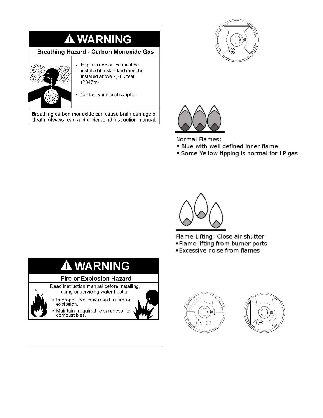
ADJUSTING AIR SHUTTER FOR HIGHER ALTI-
TUDES
The air shutter is preset with the air shutter in the open
position and for most applications changing the air
shutter is not required.
FIGURE 2. AIR SHUTTER OPEN
A correctly set burner should have a stable quiet ame.
The ame will be blue with a well dened blue inner
ame, Some yellow tipping is normal with LP gas. See
Figure 3.
FIGURE 3. NORMAL FLAMES
If ames are seen to lift from the burner ports, gradually
close the air shutter until a stable ame is achieved. See
Figure 4.
FIGURE 4. FLAME LIFTING
See Figure 5 for the appearance of the half-closed and
full-closed air shutter. Normally, this ame lifting occurs
only at altitudes above 5,400 feet.
FIGURE 5. HALF-CLOSED AND CLOSED AIR SHUTTER
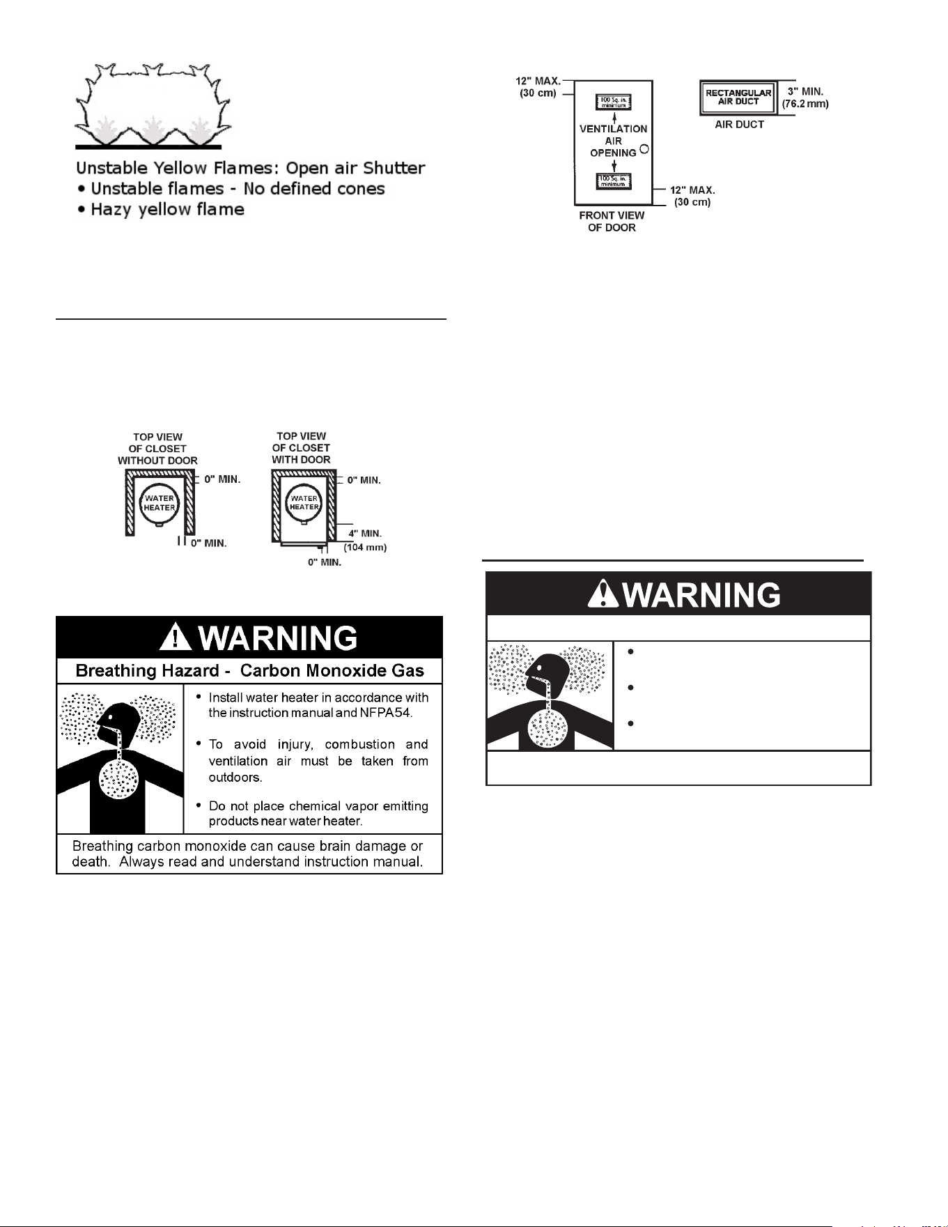
If the air shutter is closed too far, the ame will look hazy
and not have dened cones. See the example in Figure
6 (page 10). In this case, the air shutter will need to be
opened. See Figure 2.
10
FIGURE 6. UNSTABLE FLAME
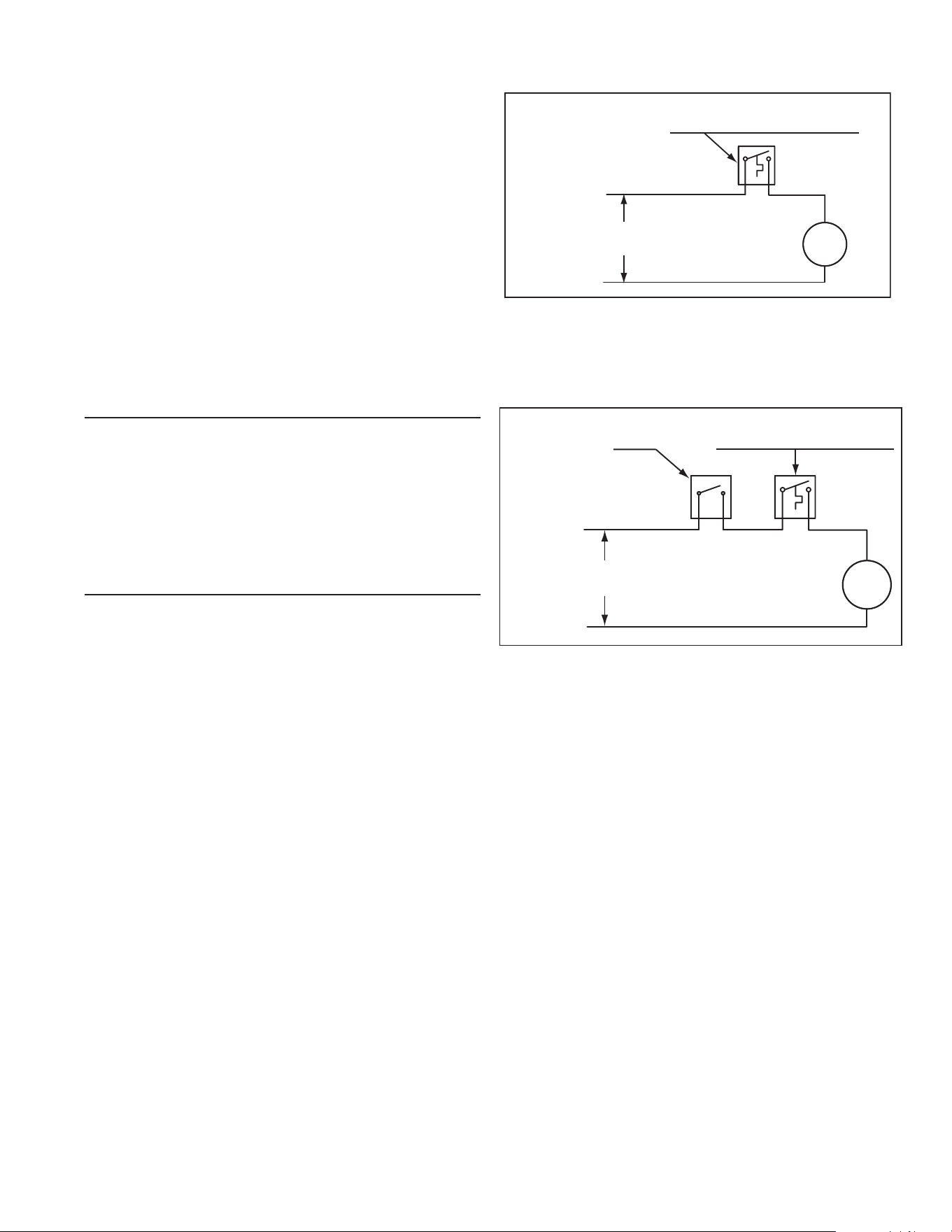
CLEARANCES
Minimum clearances between the water heater and
combustible construction are 0 inch at the sides and
rear, 4” (102 mm) at the front, and 6” (153 mm) from the
vent pipe. Clearance from the top of the jacket is 12”
(305 mm).
FIGURE 7. CLEARANCES
A gas water heater cannot operate properly without the
correct amount of air for combustion. Do not install in a
conned area such as a closet, unless you provide air
as described in Air Requirements (page 16). Never
obstruct the ow of ventilation air. If you have any doubts
or questions at all, call your gas supplier. Failure to
provide the proper amount of combustion air can result
in a re or explosion and cause death, serious bodily
injury, or property damage.
FIGURE 8. VENTILATION CLEARANCES
If this water heater will be used in beauty shops,
barber shops, cleaning establishments, or self-service
laundries with dry cleaning equipment, it is imperative
that the water heater or water heaters be installed
so that combustion and ventilation air be taken from
outside these areas.
Propellants of aerosol sprays and volatile compounds,
(cleaners, chlorine based chemicals, refrigerants, etc.)
in addition to being highly ammable in many cases,
will also change to corrosive hydrochloric acid when
exposed to the combustion products of the water
heater. The results can be hazardous, and also cause
product failure.
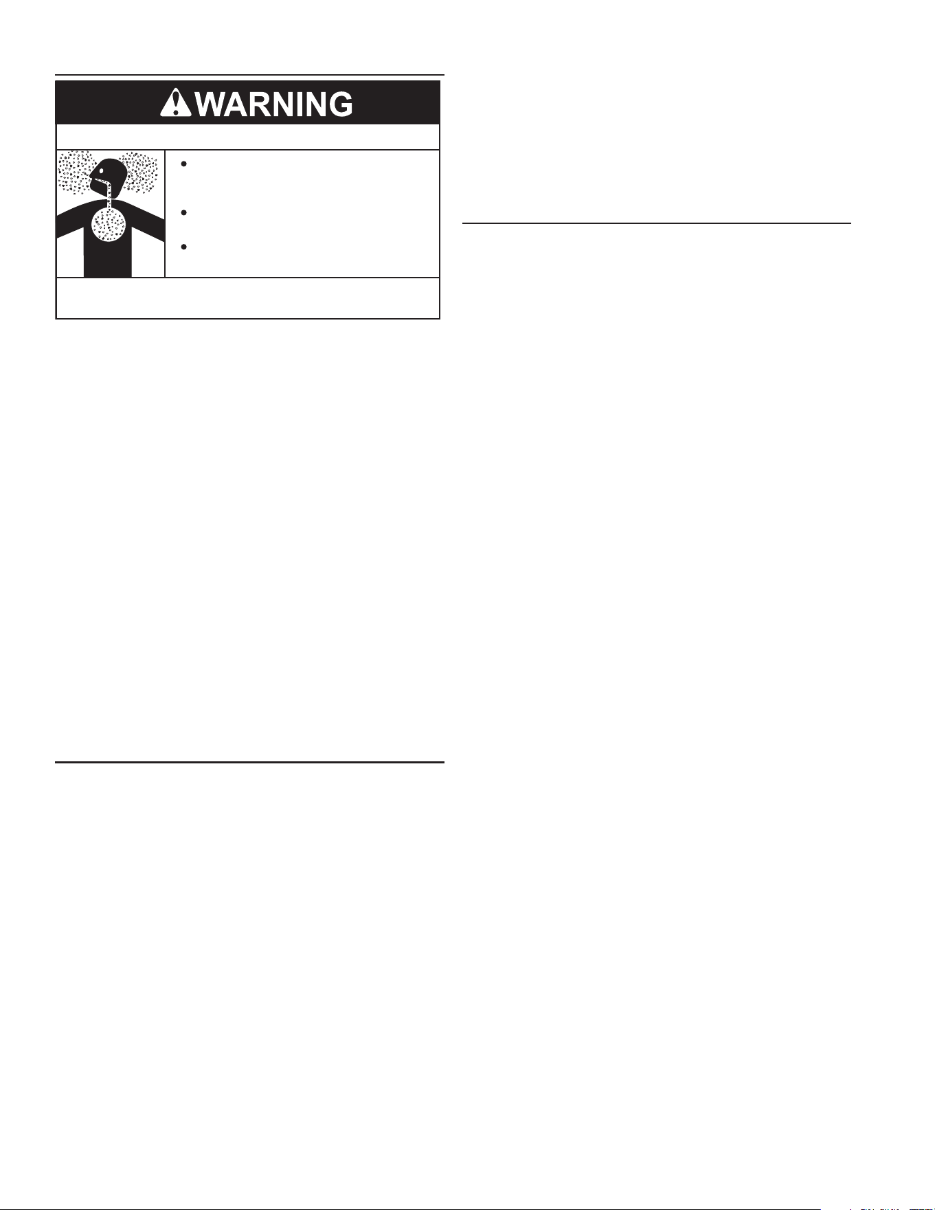
INSULATION BLANKETS
Do not obstruct water heater air intake
with insulating blanket.
Gas and carbon monoxide detectors
are available.
Install water heater in accordance with
the instruction manual.
Breathing carbon monoxide can cause brain damage or
death. Always read and understand instruction manual.
Breathing Hazard - Carbon Monoxide Gas
Insulation blankets are available to the general public
for external use on gas water heaters but are not
necessary with these products. The purpose of an
insulation blanket is to reduce the standby heat loss
encountered with storage tank heaters. The water
heaters covered by this manual meet or exceed the
Energy Policy Act standards with respect to insulation
and standby heat loss requirements, making an
insulation blanket unnecessary.
Should you choose to apply an insulation blanket to
this heater, you should follow these instructions. See
Leakage Test Points (page 33) for identication of
components mentioned below. Failure to follow these
instructions can restrict the air ow required for proper
combustion, potentially resulting in re, asphyxiation,
serious personal injury or death.
11
• DO NOT apply insulation to the top of the water
heater, as this will interfere with safe operation of the
draft hood. See Figure 18 (page 20).
• DO NOT cover the thermostat or the temperature-
pressure relief valve.
• DO NOT allow the insulation to come within 2 inches
(5 cm) of the oor to prevent blockage of combustion
air ow to the burner.
• DO NOT cover the instruction manual. Keep it on the
side of the water heater or nearby for future reference.
• DO obtain new warning and instruction labels from
the manufacturer for placement on the blanket directly
over the existing labels.
• DO inspect the insulation blanket frequently to make
certain it does not sag, thereby obstructing the
combustion air ow.
HARD WATER
Where hard water conditions exist, water softening or the
threshold type of water treatment is recommended. This
will protect the dishwashers, coffee urns, water heaters,
water piping and other equipment. See the Periodic
Removal of Lime Deposits From Tank Type Commercial
Water Heaters (page 30) for sediment and lime scale
removal procedures.
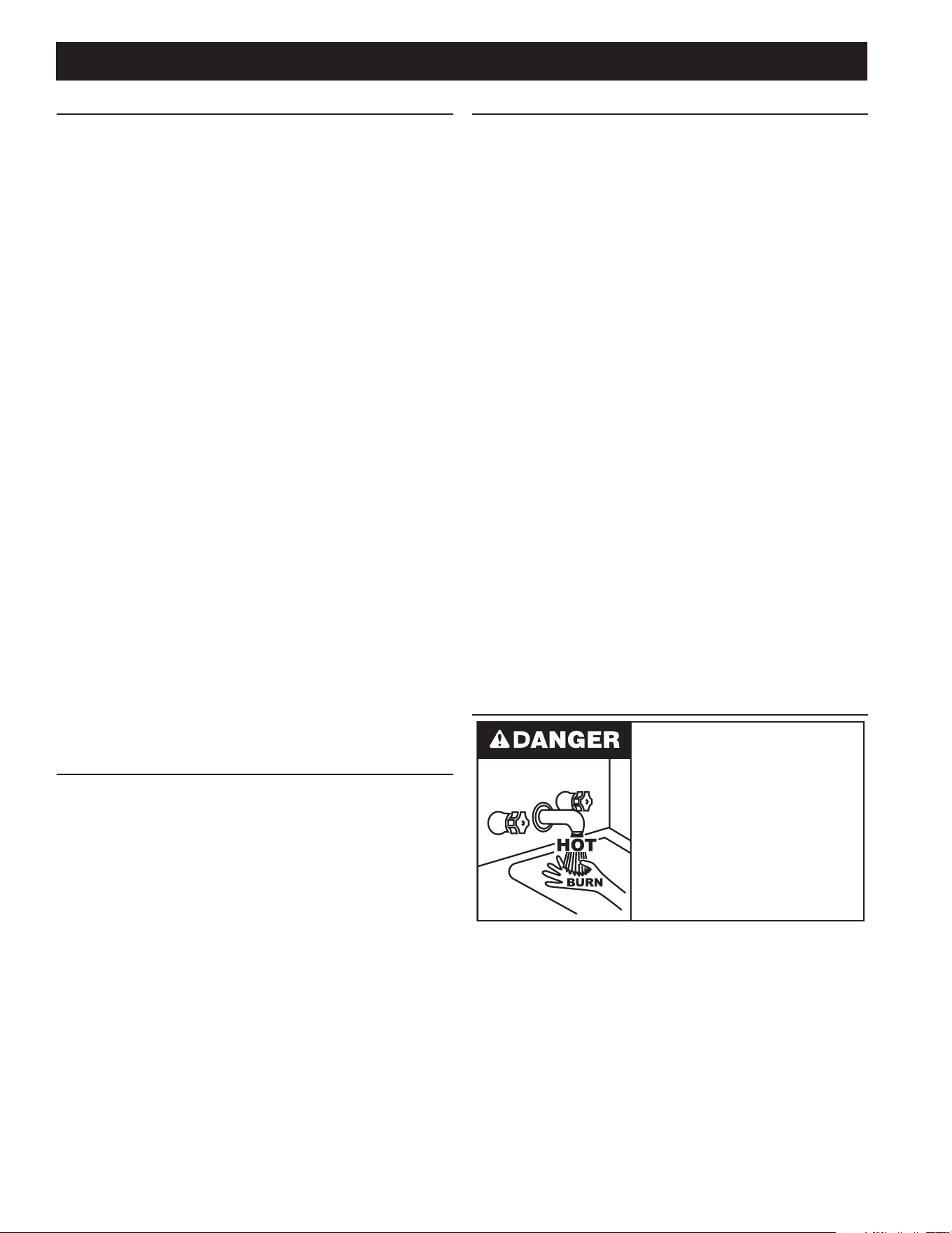
CIRCULATION PUMPS
A circulating pump is used when a system requires
a circulating loop or there is a storage tank used in
conjunction with the water heater. See Water Piping
(page 13) and Water Piping Diagrams (page 39) for
installation location of circulating pumps.
See the circulation pump wiring diagrams (Figure 9
and Figure 10) for electrical hookup information. Install
in accordance with the current edition of the National
Electrical Code, NFPA 70 or the Canadian Electrical Code,
CSA C22.1.
All bronze or stainless steel circulating pumps are
recommended for use with commercial water heaters.
Some circulating pumps are manufactured with sealed
bearings and do not require further lubrication. Some
circulating pumps must be periodically oiled. Refer to
the pump manufacturer’s instructions for lubrication
requirements.
CIRCULATING PUMP WIRING DIAGRAM
STORAGE TANK OR BUILDING RECIRCULATION
FIELD SUPPLIED TEMPERATURE CONTROL
INSTALLED IN THE STORAGE TANK
OR CIRCULATING LOOP RETURN LINE
CIRC
PUMP
MOTOR
L1 HOT
L2 NEUTRAL
120 VAC
POWER
NOTE: USE SEPARATE 120 VAC POWER
SUPPLY FOR PUMP CIRCUIT. DO NOT
SHARE POWER WITH APPLIANCE AS THIS
MAY CAUSE ELECTRICAL LINE NOISE AND
LEAD TO ERRATIC CONTROL SYSTEM
OPERATION.
FIGURE 9. STORAGE TANK/BUILDING RECIRCULATION
CIRCULATING PUMP WIRING DIAGRAM
DISHWASHER LOOP WITH TOGGLE SWITCH
FIELD SUPPLIED TEMPERATURE
CONTROL INSTALLED IN THE
CIRCULATING LOOP RETURN LINE
DISHWASHER
TOGGLE
SWITCH
CIRC
PUMP
MOTOR
L1 HOT
L2 NEUTRAL
120 VAC
POWER
NOTE: USE SEPARATE 120 VAC POWER
SUPPLY FOR PUMP CIRCUIT. DO NOT
SHARE POWER WITH APPLIANCE AS THIS
MAY CAUSE ELECTRICAL LINE NOISE AND
LEAD TO ERRATIC CONTROL SYSTEM
OPERATION.
FIGURE 10. DISHWASHER LOOP WITH TOGGLE SWITCH
12
GAS SUPPLY SYSTEMS
Low pressure building gas supply systems are dened
as those systems that cannot under any circumstances
exceed 14” W.C. (1/2 PSI Gauge). These systems do
not require pressure regulation. Measurements should
be taken to insure that gas pressures are stable and fall
within the requirements stated on the water heater rating
plate. Readings should be taken with all gas burning
equipment off (static pressure) and with all gas burning
equipment running at maximum rate (dynamic pressure).
The gas supply pressure must be stable within 1.5”
W.C. from static to dynamic pressure to provide good
performance. Pressure drops that exceed 1.5” W.C.
may cause rough starting, noisy combustion or nuisance
outages. Increases or spikes in static pressure during
off cycles may cause failure to ignite or in severe cases
damage to appliance gas valves. If your low pressure
system does not meet these requirements, the installer is
responsible for the corrections.
High Pressure building supply systems use pressures
that exceed 14” W.C. (1/2 PSI Gauge). These systems
must use eld supplied regulators to lower the gas
pressure to less than 14” W.C. (1/2 PSI Gauge).
Appliances require gas regulators that are properly
sized for the water heater input and deliver the rating
plate specied pressures. Gas supply systems where
pressure exceeds 5 PSI often require multiple regulators
to achieve desired pressures. Systems in excess of 5
PSI building pressure should be designed by gas delivery
professionals for best performance. Water heaters
connected to gas supply systems that exceed 14” W.C.
(1/2 PSI Gauge) at any time must be equipped with a gas
supply regulator.
GAS PRESSURE REQUIREMENTS
Natural gas models require a minimum gas supply
pressure of 5.0” W.C. (1.24 kPa). Propane gas models
require a minimum gas supply pressure of 11” W.C. (2.74
kPa). The minimum supply pressure is measured while
gas is owing (dynamic pressure). The supply pressure
(dynamic) should never fall below the specied minimum
supply pressure. The supply pressure should be
measured with all gas red appliances connected to the
common main ring at full capacity. If the supply pressure
drops more than 1.5” W.C. (0.37 kPa) as gas begins
to ow to the water heater then the supply gas system
including the gas line and/or the gas regulator may be
restricted or undersized. See Water Piping Diagrams
(page 39) and Gas Piping (page 20). The gas valve
on all models has a maximum gas supply pressure limit
of 14” W.C. (3.48 kPa) The maximum supply pressure is
measured while gas is not owing (static pressure).
SUPPLY GAS REGULATOR
The maximum allowable gas supply pressure for this
water heater is 14.0 inches W.C. (3.48 kPa). Install a
positive lock-up gas pressure regulator in the gas supply
line if inlet gas pressure can exceed 14.0 inches W.C.
(3.48 kPa) at any time. Regulators must be sized/used
according to manufacturer’s specications.
If a positive lock-up regulator is required follow these
instructions:
1. Positive lock-up gas pressure regulators must be rated
at or above the input Btu/hr rating of the water heater
they supply.
2. Positive lock-up gas pressure regulator(s) should be
installed no closer than 3 feet (1 meter) and no farther
than 8 feet (2.4 meters) of equivalent length from the
water heater’s inlet gas connection.
3. After installing the positive lock-up gas pressure
regulator(s), and while the water heater is operating,
an initial nominal supply pressure setting of 7.0” W.C.
is recommended and will generally provide good
water heater operation. Some addition adjustment
maybe required later to maintain a steady gas supply
pressure.
4. When installing multiple water heaters in the same
gas supply system it is recommended that individual
positive lock-up gas pressure regulators be installed at
each unit.
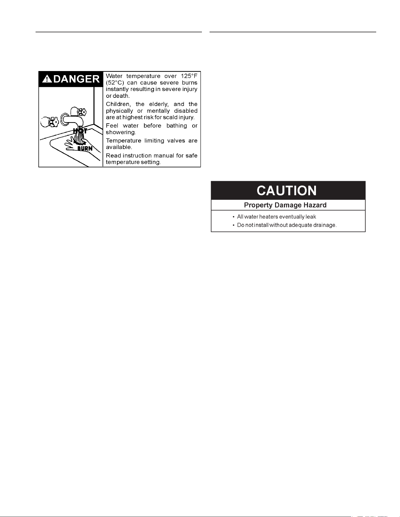
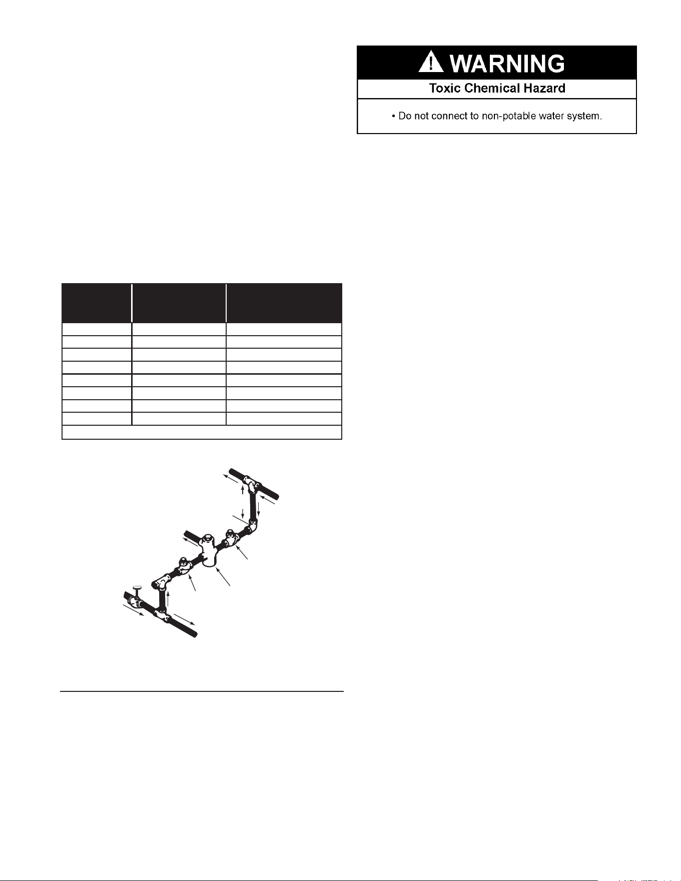
MIXING VALVES
Water temperature over 125°F (52°C)
can cause severe burns instantly
resulting in severe injury or death.
Children, the elderly and the physically
or mentally disabled are at highest risk
for scald injury.
Feel water before bathing or showering.
Temperature limiting devices such as
mixing valves must be installed when
required by codes and to ensure safe
temperatures at fixtures.
Water heated to a temperature which will satisfy clothes
washing, dish washing, and other sanitizing needs can
scald and cause permanent injury upon contact. Short
repeated heating cycles caused by small hot water uses
can cause temperatures at the point of use to exceed the
water heater’s temperature setting by up to 20°F (11°C).
Some people are more likely to be permanently injured
by hot water than others. These include the elderly,
children, the inrm and the physically/mentally disabled.
INSTALLATION REQUIREMENTS
13
Table 3 shows the approximate time-to-burn relationship
for normal adult skin. If anyone using hot water provided
by the water heater being installed ts into one of these
groups or if there is a local code or state law requiring a
certain water temperature at the point of use, then special
precautions must be taken.
In addition to using the lowest possible temperature
setting that satises demand of the application, a mixing
valve should be installed at the water heater or at hot
water taps to further reduce system water temperature.
See Figure 11 (page 13).
Mixing valves are available at plumbing supply stores.
Consult a Qualied Installer or Service Agency. Follow
mixing valve manufacturer’s instructions for installation of
the valves.
TABLE 3. APPROXIMATE TIME-TO-BURN
Water
Temperature °F
Time for
1st Degree Burn
(Less Severe Burns)
Time for Permanent Burns
2nd & 3rd Degree
(Most Severe Burns)
110
(normal shower temp.)
116 (pain threshold)
116 35 minutes 45 minutes
122 1 minute 5 minutes
131 5 seconds 25 seconds
140 2 seconds 5 seconds
149 1 second 2 seconds
154 instantaneous 1 second
(U.S. Government Memorandum, C.P.S.C., Peter L. Armstrong, Sept. 15,1978)
HOT WATER
OUTLET
TO TANK
INLET
CHECK
VALVE
MIXING
VALVE
COLD
WATER
INLET
TEMPERED WATER
OUTLET
12” TO 15”
(30-38 cm)
CHECK
VALVE
FIGURE 11. MIXING VALVE
WATER PIPING
WATER (POTABLE) HEATING AND SPACE HEATING
This water heater shall not be connected to any heating
systems or component(s) used with a non-potable water
heating appliance.
All piping components connected to this unit for space
heating applications shall be suitable for use with potable
water. Toxic chemicals, such as those used for boiler
treatment shall not be introduced into this system.
When the system requires water for space heating at
temperatures higher than required for domestic water
purposes, a mixing valve must be installed. See Figure 11
(page 13) for suggested piping arrangement.
These water heaters cannot be used in space heating
applications only.
CLOSED WATER SYSTEMS
Water supply systems may, because of code
requirements or such conditions as high line pressure,
among others, have installed devices such as pressure
reducing valves, check valves, and back ow preventers.
Devices such as these cause the water system to be a
closed system.
THERMAL EXPANSION
As water is heated, it expands (thermal expansion). In
a closed system the volume of water will grow when it
is heated. As the volume of water grows there will be a
corresponding increase in water pressure due to thermal
expansion. Thermal expansion can cause premature tank
failure (leakage). This type of failure is not covered under
the limited warranty. Thermal expansion can also cause
intermittent temperature-pressure relief valve operation:
water discharged from the valve due to excessive
pressure build up. This condition is not covered under the
limited warranty. The temperature-pressure relief valve is
not intended for the constant relief of thermal expansion.
A properly sized thermal expansion tank must be installed
on all closed systems to control the harmful effects of
thermal expansion. Contact a local plumbing service
technician to have a thermal expansion tank installed.
14
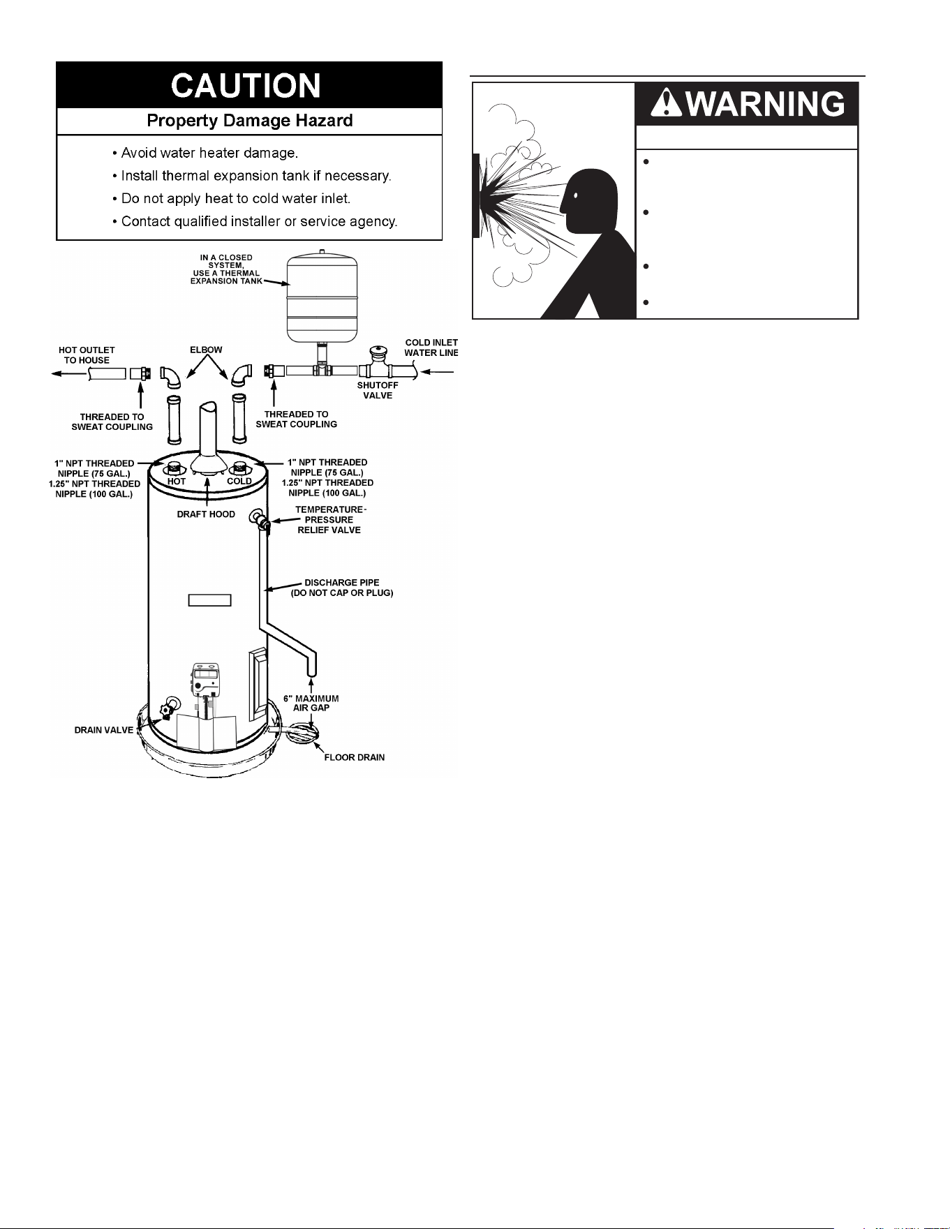
FIGURE 12. TYPICAL PIPING ARRANGEMENT
Note: To protect against untimely corrosion of hot and
cold water ttings, it is strongly recommended that
dielectric unions or couplings be installed on this water
heater when connected to copper pipe.
Figure 12 shows the typical attachment of the water
piping to the water heater. The water heater is equipped
with 1” NPT threaded nipple (75 gallon models) or
1.25” NPT threaded nipple (100 gallon models) water
connections.
TEMPERATURE-PRESSURE RELIEF VALVE
Explosion Hazard
Temperature-Pressure Relief Valve
must comply with ANSI Z21.22-
CSA 4.4 and ASME code.
Properly sized temperature-
pressure relief valve must be
installed in opening provided.
Can result in overheating and
excessive tank pressure.
Can cause serious injury or death.
This water heater is provided with a properly rated/
sized and certied combination temperature-pressure
relief valve (T&P valve) by the manufacturer. The valve
is certied by a nationally recognized testing laboratory
that maintains periodic inspection of production of listed
equipment of materials as meeting the requirements for
relief valves for hot water supply systems, ANSI Z21.22 •
CSA 4.4, and the code requirements of ASME. If replaced,
the new T&P valve must meet the requirements of local
codes, but not less than a combination temperature-
pressure relief valve rated/sized and certied as indicated
in the above paragraph. The new valve must be marked
with a maximum set pressure not to exceed the marked
hydrostatic working pressure of the water heater (150
psi = 1,035 kPa) and a discharge capacity not less than
the water heater Btu/hr or kW input rate as shown on the
water heater’s model rating label.
Note: In addition to the factory installed
temperature-pressure relief valve on the water heater,
each remote storage tank that may be installed and
piped to a water heating appliance must also have its
own properly sized, rated, and approved temperature-
pressure relief valve installed. Call the toll free technical
support phone number listed on the back cover of this
manual for technical assistance in sizing a temperature-
pressure relief valve for remote storage tanks.
For safe operation of the water heater, the temperature-
pressure relief valve must not be removed from its
designated opening nor plugged. The temperature-
pressure relief valve must be installed directly into the
tting of the water heater designed for the relief valve.
Install discharge piping so that any discharge will exit
the pipe within 6 inches (15.2 cm) above an adequate
oor drain, or external to the building. In cold climates
it is recommended that it be terminated at an adequate
drain inside the building. Be certain that no contact is
made with any live electrical part. The discharge opening
must not be blocked or reduced in size under any
circumstances. Excessive length, over 30 feet (9.14 m),
or the use of more than four elbows can cause restriction
and reduce the discharge capacity of the valve.
15
No valve or other obstruction is to be placed between the
temperature-pressure relief valve and the tank. Do not
connect discharge piping directly to the drain unless a
6” (15.2 cm) air gap is provided. To prevent bodily injury,
hazard to life, or property damage, the relief valve must
be allowed to discharge water in adequate quantities
should circumstances demand. If the discharge pipe is
not connected to a drain or other suitable means, the
water ow may cause property damage.
Water Damage Hazard
•
Temperature-Pressure Relief Valve discharge
pipe must terminate at adequate drain.
CAUTION
T&P Valve Discharge Pipe Requirements:
• Shall not be smaller in size than the outlet pipe size
of the valve, or have any reducing couplings or other
restrictions.
• Shall not be plugged or blocked.
• Shall not be exposed to freezing temperatures.
• Shall be of material listed for hot water distribution.
• Shall be installed so as to allow complete drainage
of both the temperature-pressure relief valve and the
discharge pipe.
• Must terminate a maximum of six inches above a
oor drain or external to building. In cold climates, it is
recommended that discharge pipe be terminated at an
adequate drain inside building.
• Shall not have any valve or other obstruction between
the relief valve and the drain.
Burn hazard.
Hot water discharge.
Keep clear of Temperature-
Pressure Relief Valve
discharge outlet.
The temperature-pressure relief valve must be manually
operated at least twice a year. Caution should be taken to
ensure the following:
1. No one is in front of or around the outlet of the
temperature-pressure relief valve discharge line.
2. The water manually discharged will not cause any
bodily injury or property damage because the water
may be extremely hot.
If, after manually operating the valve, it fails to completely
reset and continues to release water, immediately close
the cold water inlet to the water heater, follow the draining
instructions in this manual, and replace the temperature-
pressure relief valve with a properly rated/sized new one.
Note: The purpose of a temperature-pressure relief valve
is to prevent excessive temperatures and pressures in
the storage tank. The T&P valve is not intended for the
constant relief of thermal expansion. A properly sized
thermal expansion tank must be installed on all closed
systems to control thermal expansion, see Figure 12
(page 13).
If you do not understand these instructions or have any
questions regarding the temperature-pressure relief valve
call the toll free number listed on the back cover of this
manual for technical assistance.
FILLING THE WATER HEATER
Never use this water heater unless it is completely full
of water. To prevent damage to the tank, the tank must
be lled with water. Water must ow from the hot water
faucet before turning on the gas to the water heater.
To ll the water heater with water:
1. Close the water heater drain valve by turning the
handle to the right (clockwise). The drain valve is on
the lower front of the water heater.
2. Open the cold water supply valve to the water heater.
NOTE: The cold water supply valve must be left open
when the water heater is in use.
3. To insure complete lling of the tank, allow air to exit
by opening the nearest hot water faucet. Allow water
to run until a constant ow is obtained. This will let air
out of the water heater and the piping.
4. Check all water piping and connections for leaks.
Repair as needed.
16
AIR REQUIREMENTS
Breathing Hazard - Carbon Monoxide Gas
Install water heater in accordance with
the Instruction Manual and NFPA 54 or
CAN/CSA-B149.1.
To avoid injury, combustion and ventilation
air must be taken from outdoors.
Do not place chemical vapor emitting
products near water heater.
Breathing carbon monoxide can cause brain damage or
death. Always read and understand instruction manual.
For safe operation, an adequate supply of fresh
uncontaminated air for combustion and ventilation must
be provided.
An insufcient supply of air can cause recirculation of
combustion products resulting in contamination that may
be hazardous to life. Such a condition often will result
in a yellow, luminous burner ame, causing sooting of
the combustion chamber, burners, and ue tubes, and
creates a risk of asphyxiation.
Do not install the water heater in a conned space unless
an adequate supply of air for combustion and ventilation
is brought in to that space using the methods described
in Conned Space (page 16) that follows later in this
manual.
Never obstruct the ow of ventilation air. If you have any
doubts or questions at all, call your gas supplier. Failure
to provide the proper amount of combustion air can result
in a re or explosion and cause property damage, serious
bodily injury or death.
UNCONFINED SPACE
An unconned space is one in which the volume is not
less than 50 cubic feet per 1,000 Btu/hr (4.8 cubic meters
per kW) of the total input rating of all appliances installed
in the space. Rooms communicating directly with the
space in which the appliances are installed, through
openings not furnished with doors, are considered a part
of the unconned space.
Makeup air requirements for the operation of exhaust
fans, kitchen ventilation systems, clothes dryers and
replaces shall also be considered in determining the
adequacy of a space to provide combustion, ventilation
and dilution air.
UNUSUALLY TIGHT CONSTRUCTION
In unconned spaces in buildings, inltration may be
adequate to provide air for combustion, ventilation and
dilution of ue gases. However, in buildings of unusually
tight construction (for example, weather stripping, heavily
insulated, caulked, vapor barrier, etc.) additional air must
be provided using the methods described in that follows.
CONFINED SPACE
A conned space is one in which the volume is less than
50 cubic feet per 1,000 Btu/hr (4.8 cubic meters per kW)
of the total input rating of all appliances installed in the
space.
Openings must be installed to provide fresh air for
combustion, ventilation and dilution in conned spaces.
The required size for the openings is dependent on the
method used to provide fresh air to the conned space
and the total Btu/hr input rating of all appliances installed
in the space.
DIRECT VENT APPLIANCES
Appliances installed in a direct-vent conguration
that derives all air for combustion from the outdoor
atmosphere through sealed intake air piping are not
factored in the total appliance input Btu/hr calculations
used to determine the size of openings providing fresh air
into conned spaces.
EXHAUST FANS
Where exhaust fans are installed, additional air shall be
provided to replace the exhausted air. When an exhaust
fan is installed in the same space with a water heater,
sufcient openings to provide fresh air must be provided
that accommodate the requirements for all appliances
in the room and the exhaust fan. Undersized openings
will cause air to be drawn into the room through the
water heater’s vent system causing poor combustion.
Sooting, serious damage to the water heater and the risk
of re or explosion may result. It can also create a risk of
asphyxiation.
LOUVERS AND GRILLES
The free areas of the fresh air openings in the
instructions that follow do not take in to account the
presence of louvers, grilles or screens in the openings.
The required size of openings for combustion, ventilation
and dilution air shall be based on the “net free area” of
each opening. Where the free area through a design
of louver or grille or screen is known, it shall be used in
calculating the size of opening required to provide the
free area specied. Where the louver and grille design
17
and free area are not known, it shall be assumed that
wood louvers will have 25% free area and metal louvers
and grilles will have 75% free area. Non motorized
louvers and grilles shall be xed in the open position.
FRESH AIR OPENINGS FOR CONFINED SPACES
The following instructions shall be used to calculate the
size, number and placement of openings providing fresh
air for combustion, ventilation and dilution in conned
spaces. The illustrations shown in this section of the
manual are a reference for the openings that provide
fresh air into conned spaces only. Do not refer to these
illustrations for the purpose of vent installation. See
Venting (page 19) for complete venting instructions.
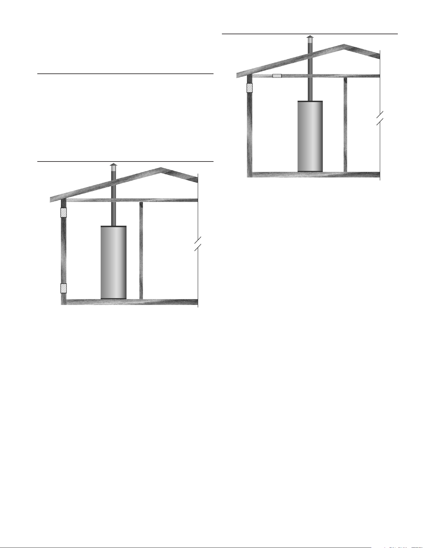
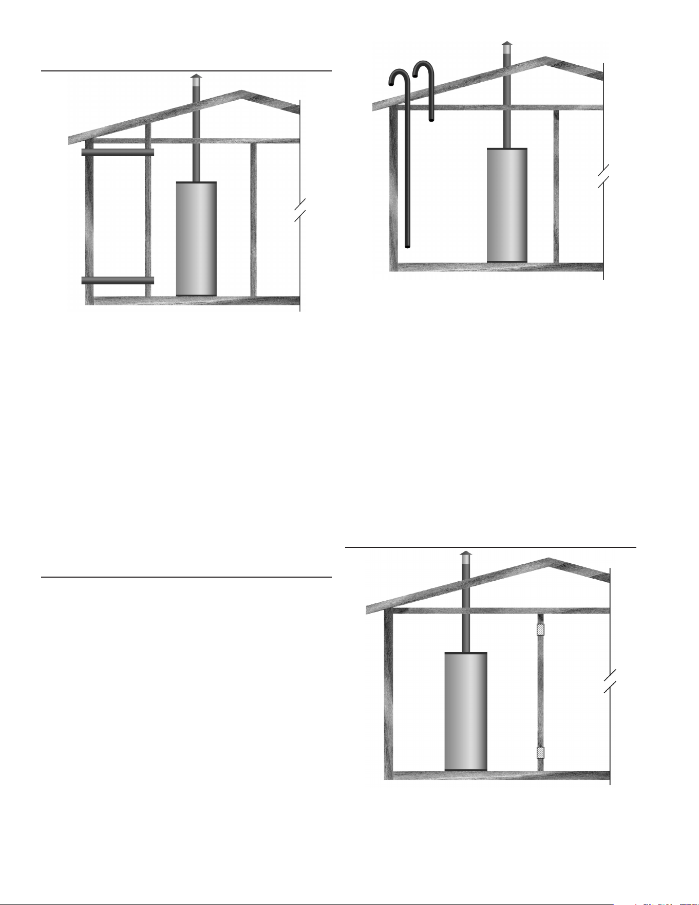
OUTDOOR AIR THROUGH TWO OPENINGS
FIGURE 13. FRESH AIR FROM TWO OPENINGS
The conned space shall be provided with two permanent
openings, one commencing within 12 inches (300 mm)
of the top and one commencing within 12 inches (300
mm) of the bottom of the enclosure. The openings shall
communicate directly with the outdoors. See Figure 13 .
Each opening shall have a minimum free area of 1
square inch per 4,000 Btu/hr (550 mm
2
per kW) of the
aggregate input rating of all appliances installed in the
enclosure. Each opening shall not be less than 100
square inches (645 cm
2
).
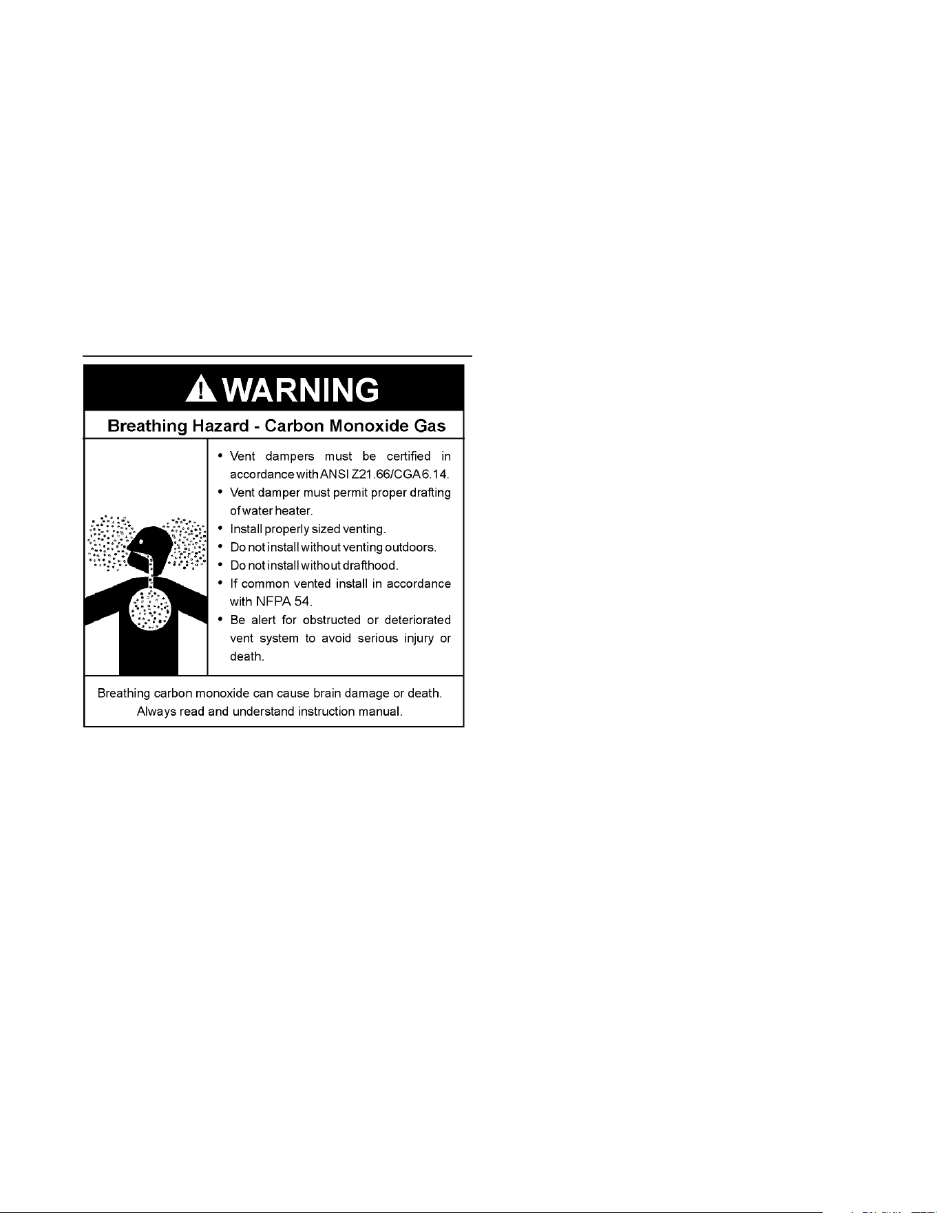
OUTDOOR AIR THROUGH ONE OPENING
FIGURE 14. FRESH AIR FROM ONE OPENING
Alternatively a single permanent opening, commencing
within 12 inches (300 mm) of the top of the enclosure,
shall be provided. See Figure 14.
The water heater shall have clearances of at least 1 inch
(25 mm) from the sides and back and 6 inches (150 mm)
from the front of the appliance. The opening shall directly
communicate with the outdoors or shall communicate
through a vertical or horizontal duct to the outdoors or
spaces that freely communicate with the outdoors and
shall have a minimum free area of the following:
1. One square inch per 3000 Btu/hr (733 mm
2
per kW)
of the total input rating of all appliances located in the
enclosure, and
2. Not less than the sum of the areas of all vent
connectors in the space.
18
OUTDOOR AIR THROUGH TWO HORIZONTAL
DUCTS
FIGURE 15. FRESH AIR FROM TWO HORIZONTAL DUCTS
The conned space shall be provided with two permanent
horizontal ducts, one commencing within 12 inches (300
mm) of the top and one commencing within 12 inches
(300 mm) of the bottom of the enclosure. The horizontal
ducts shall communicate directly with the outdoors. See
Figure 15.
Each duct opening shall have a minimum free area of 1
square inch per 2,000 Btu/hr (1100 mm
2
per kW) of the
aggregate input rating of all appliances installed in the
enclosure.
When ducts are used, they shall be of the same cross
sectional area as the free area of the openings to which
they connect. The minimum dimension of rectangular air
ducts shall be not less than 3 inches.
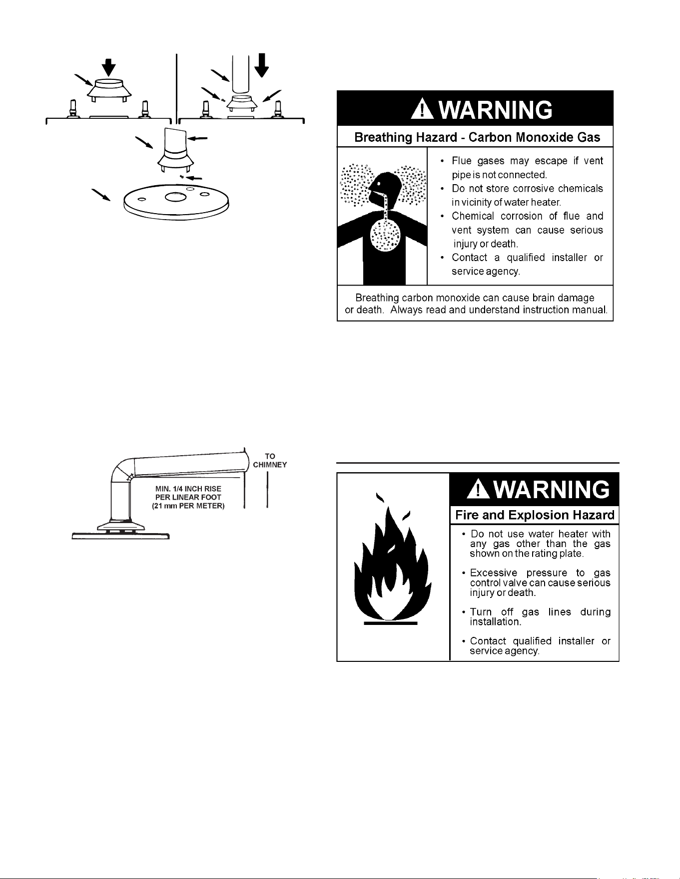
OUTDOOR AIR THROUGH TWO VERTICAL DUCTS
The illustrations shown in this section of the manual are
a reference for the openings that provide fresh air into
conned spaces only.
DO NOT refer to these illustrations for the purpose of
vent installation. See Venting (page 19) for complete
venting instructions.
FIGURE 16. FRESH AIR FROM TWO VERTICAL DUCTS
The conned space shall be provided with two permanent
vertical ducts, one commencing within 12 inches (300
mm) of the top and one commencing within 12 inches
(300 mm) of the bottom of the enclosure. The vertical
ducts shall communicate directly with the outdoors. See
Figure 16.
Each duct opening shall have a minimum free area of 1
square inch per 4,000 Btu/hr (550 mm
2
per kW) of the
aggregate input rating of all appliances installed in the
enclosure.
When ducts are used, they shall be of the same cross
sectional area as the free area of the openings to which
they connect. The minimum dimension of rectangular air
ducts shall be not less than 3 inches.
AIR FROM OTHER INDOOR SPACES
FIGURE 17. AIR FROM INDOOR SPACES
19
The conned space shall be provided with two permanent
openings, one commencing within 12 inches (300 mm) of
the top and one commencing within 12 inches (300 mm)
of the bottom of the enclosure. See Figure 17.
Each opening shall communicate directly with an
additional room(s) of sufcient volume so that the
combined volume of all spaces meets the criteria for an
unconned space.
Each opening shall have a minimum free area of 1
square inch per 1,000 Btu/hr (2200 mm
2
per kW) of the
aggregate input rating of all appliances installed in the
enclosure. Each opening shall not be less than 100
square inches (645 cm
2
).
VENTING
Water heaters covered by these instructions are Category
I, Natural Draft appliances.
If the water heater is being installed as a replacement
for an existing heater in pre-existing venting, a thorough
inspection of existing venting system must be performed
prior to any installation work.
VENT DAMPERS - Any vent damper, whether it is
operated thermally or otherwise must be removed if its
use inhibits proper drafting of the water heater.
Thermally Operated Vent Dampers: this gas-red water
heater has a thermal efciency at or above 80% which
may produce a relatively low ue gas temperature.
Such temperatures may not be high enough to properly
open thermally operated vent dampers. This would
cause spillage of the ue gases and may cause carbon
monoxide poisoning. Vent dampers must bear evidence
of certication as complying with the current edition of
the American National Standard ANSI Z21.66 CGA 6.14
(covering electrically and mechanically actuated vent
dampers). Before installation of any vent damper, consult
the local gas utility for further information.
To insure proper venting of this gas-red water heater,
the correct vent pipe diameter must be utilized. Any
additions or deletions of other gas appliances on a
common vent with this water heater may adversely affect
the operation of the water heater. Consult your gas
supplier if any such changes are planned.
For proper venting in certain installations, a larger
diameter vent pipe may be necessary. Consult your gas
supplier to aid you in determining the proper venting
for your water heater from the vent tables in the current
edition of the National Fuel Gas Code ANSI Z223.1/NFPA 54
or the Natural Gas and Propane Installation Code CAN\CSA
B 149.1.
Periodically check the venting system for signs of
obstruction or deterioration and replace if needed.
The combustion and ventilation air ow must not be
obstructed.
The water heater with draft hood installed must be
connected to a chimney or listed vent pipe system,
which terminates to the outdoors. Never operate the
water heater unless it is vented to the outdoors and has
adequate air supply to avoid risks of improper operation,
explosion or asphyxiation.
• For proper draft hood attachment, the draft hood legs
may be angled slightly inward.
• Place the draft hood legs in the receiving holes on the
top of the water heater. The legs will snap in the holes
to give a tight t. Secure draft hood with the supplied
brackets.
• Place the vent pipe over the draft hood. With the vent
pipe in position, drill a small hole through both the
vent pipe and draft hood. Secure them together with a
sheet metal screw. See Figure 18 (page 20).
Obstructed or deteriorated vent systems may present
serious health risk or asphyxiation.
20
Draft Hood
Draft Hood
Top of Heater
Screw
Vent to outdoors
or chimney
Screw
Vent
FIGURE 18. DRAFT HOOD ATTACHMENT
The vent pipe from the water heater must be no less
than the diameter of the draft hood outlet on the water
heater and must slope upward at least 1/4 inch per
linear foot (21 mm per meter). See Figure 19 (page
20).
All vent gases must be completely vented to the
outdoors of the structure (dwelling). Install only the draft
hood provided with the new water heater and no other
draft hood.
Vent pipes must be secured at each joint with sheet
metal screws.
FIGURE 19. VENT PIPE MINIMUM UPWARD SLOPE
There must be a minimum of 6” (153 mm) clearance
between single wall vent pipe and any combustible
material. Fill and seal any clearance between single
wall vent pipe and combustible material with mortar
mix, cement, or other noncombustible substance. For
other than single wall, follow vent pipe manufacturer’s
clearance specications. To insure a tight t of the vent
pipe in a brick chimney, seal around the vent pipe with
mortar mix cement.
Failure to have required clearances between vent piping
and combustible material will result in a re hazard.
Be sure vent pipe is properly connected to prevent
escape of dangerous ue gases which could cause
deadly asphyxiation.
Chemical vapor corrosion of the ue and vent system
may occur if air for combustion contains certain chemical
vapors. Spray can propellants, cleaning solvents,
refrigerator and air conditioner refrigerants, swimming
pool chemicals, calcium and sodium chloride, waxes,
bleach and process chemicals are typical compounds
which are potentially corrosive.
GAS PIPING
Contact your local gas service company to ensure
that adequate gas service is available and to review
applicable installation codes for your area.
Size the main gas line in accordance with Table 4 and
21
Table 5. The sizes shown are for straight lengths of pipe
at 0.5 in. W.C. pressure drop, which is considered normal
for low pressure systems. Note: Fittings such as elbows,
tees and line regulators will add to the pipe pressure
drop. Also refer to the current editions of the National
Fuel Gas Code (NFPA 54) or Natural Gas and Propane
Installation Code (CAN/CSA B149.1).
Make sure gas supplied is same type listed on model
rating plate. The inlet gas pressure must not exceed 14
inch water column (2.6 kPa) for natural and propane
(L.P.) gas. The minimum inlet gas pressure shown on
rating plate is that which will permit ring at rated input.
If the gas control valve is subjected to pressures
exceeding 1/2 pound per square inch (3.5 kPa), the
damage to the gas control valve could result in a re or
explosion from leaking gas.
If the main gas line shut-off serving all gas appliances is
used, also turn “off” the gas at each appliance. Leave all
gas appliances shut “off” until the water heater installation
is complete.
A gas line of sufcient size must be run to the water
heater. Consult the current edition of National Fuel Gas
Code ANSI Z223.1/NFPA 54 or the Natural Gas and Propane
Installation Code CAN/CSA B149.1 and your gas supplier
concerning pipe size.
The gas piping must include the following:
• A readily accessible manual shut off valve in the gas
supply line serving the water heater, and
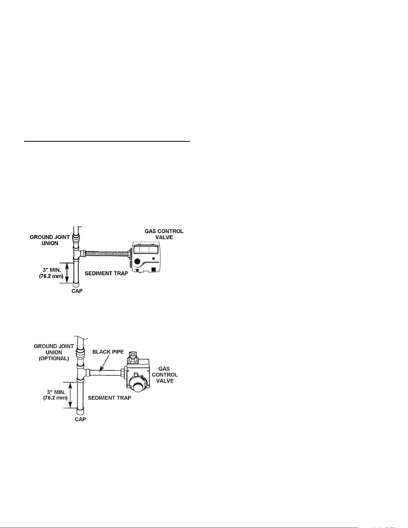
• A sediment trap ahead of the gas control valve to help
prevent dirt and foreign materials from entering the
gas control valve.
• A exible gas connector or a ground joint union
between the shut off valve and control valve to permit
servicing of the unit.
Be sure to check all the gas piping for leaks before
lighting the water heater. Use a soapy water solution, not
a match or open ame. Rinse off soapy solution and wipe
dry.
The minimum inlet gas pressure shown on the rating
plate is that which will permit ring at the rated input.
GAS SUPPLY LINE SIZES (IN INCHES)* MAXIMUM CAPACITY
OF PIPE IN CUBIC FEET PER HOUR
TABLE 4. INPUT IN THOUSANDS (BTU/HR)
LENGTH
IN
FEET
NOMINAL IRON PIPE SIZES (
INCHES
)
1/2" 3/4" 1" 1 1/4" 1 1/2" 2" 2 1/2" 3" 4"
10 175 360 680 1400 2100 3960 6300 11000 23000
20 120 250 465 950 1460 2750 4360 7700 15800
30 97 200 375 770 1180 2200 3520 6250 12800
40 82 170 320 660 990 1900 3000 5300 10900
50 73 151 285 580 900 1680 2650 4750 9700
60 66 138 260 530 810 1520 2400 4300 8800
70 61 125 240 490 750 1400 2250 3900 8100
80 57 118 220 460 690 1300 2050 3700 7500
90 53 110 205 430 650 1220 1950 3450 7200
100 50 103 195 400 620 1150 1850 3250 6700
125 44 93 175 360 550 1020 1650 2950 6000
150 40 84 160 325 500 950 1500 2650 5500
175 37 77 145 300 460 850 1370 2450 5000
200 35 72 135 280 430
800
1280 2280
4600
TABLE 5. INPUT IN KW
LENGTH
IN
METERS
NOMINAL IRON PIPE SIZES (
INCHES
)
1/2" 3/4" 1" 1 1/4" 1 1/2" 2" 2 1/2" 3" 4"
3 51 105 199 410 615 1160 1845 3221 6735
6 35 73 142 278 428 805 1277 2255 4626
9 28 59 110 225 346 644 1031 1830 3748
12 24 50 94 193 290 556 878 1552 3192
15 21 44 83 170 264 492 776 1391 2840
18 19 40 76 155 237 445 703 1259 2577
21 18 37 70 143 220 410 659 1142 2372
24 17 35 64 135 202 381 600 1083 2196
27 16 32 60 126 190 357 571 1010 2108
31 15 30 57 117 182 337 542 952 1962
38 13 27 51 105 161 299 483 864 1757
46 12 25 47 95 146 278 439 776 1610
53 11 23 42 88 135 249 401 717 1464
61 10 21 40 82 126 234 375 688 1347
Use pipe joint compound or teon tape marked as being
resistant to the action of petroleum [Propane (L.P.)]
gases.
The water heater and its gas connection must be leak
tested before placing the water heater in operation.
22
The water heater and its individual shut-off valve shall
be disconnected from the gas supply piping system
during any pressure testing of that system at test
pressures in excess of 1/2 pound per square inch (3.5
kPa). It shall be isolated from the gas supply piping
system by closing its individual manual shut-off valve
during any pressure testing of the gas supply piping
system at test pressures equal to or less than 1/2 pound
per square inch (3.5 kPa).
Connecting the gas piping to the gas control valve of the
water heater can be accomplished by either of the two
methods shown in Figure 20 and Figure 21.
SEDIMENT TRAPS
A sediment trap shall be installed as close to the inlet of
the water heater as practical at the time of water heater
installation. The sediment trap shall be either a tee
tting with a capped nipple in the bottom outlet or other
device recognized as an effective sediment trap. If a tee
tting is used, it shall be installed in conformance with
one of the methods of installation shown in Figure 20
and Figure 21.
FIGURE 20. GAS PIPING WITH FLEXIBLE CONNECTOR.
FIGURE 21. GAS PIPING WITH BLACK IRON PIPE
Contaminants in the gas lines may cause improper
operation of the gas control valve that may result in re or
explosion. Before attaching the gas line be sure that all
gas pipe is clean on the inside. To trap any dirt or foreign
material in the gas supply line, a sediment trap must be
incorporated in the piping. The sediment trap must be
readily accessible. Install in accordance with the “Gas
Piping” section. Refer to the current edition of the National
Fuel Gas Code, ANSI Z223.1/NFPA 54 or the Natural Gas and
Propane Installation Code CAN/CSA B149.1.
23
FOR YOUR SAFETY READ BEFORE LIGHTING
WARNING:
FLAMMABLE
If you do not follow these instructions exactly, a
fire or explosion may result causing property damage, personal
injury or loss of life.
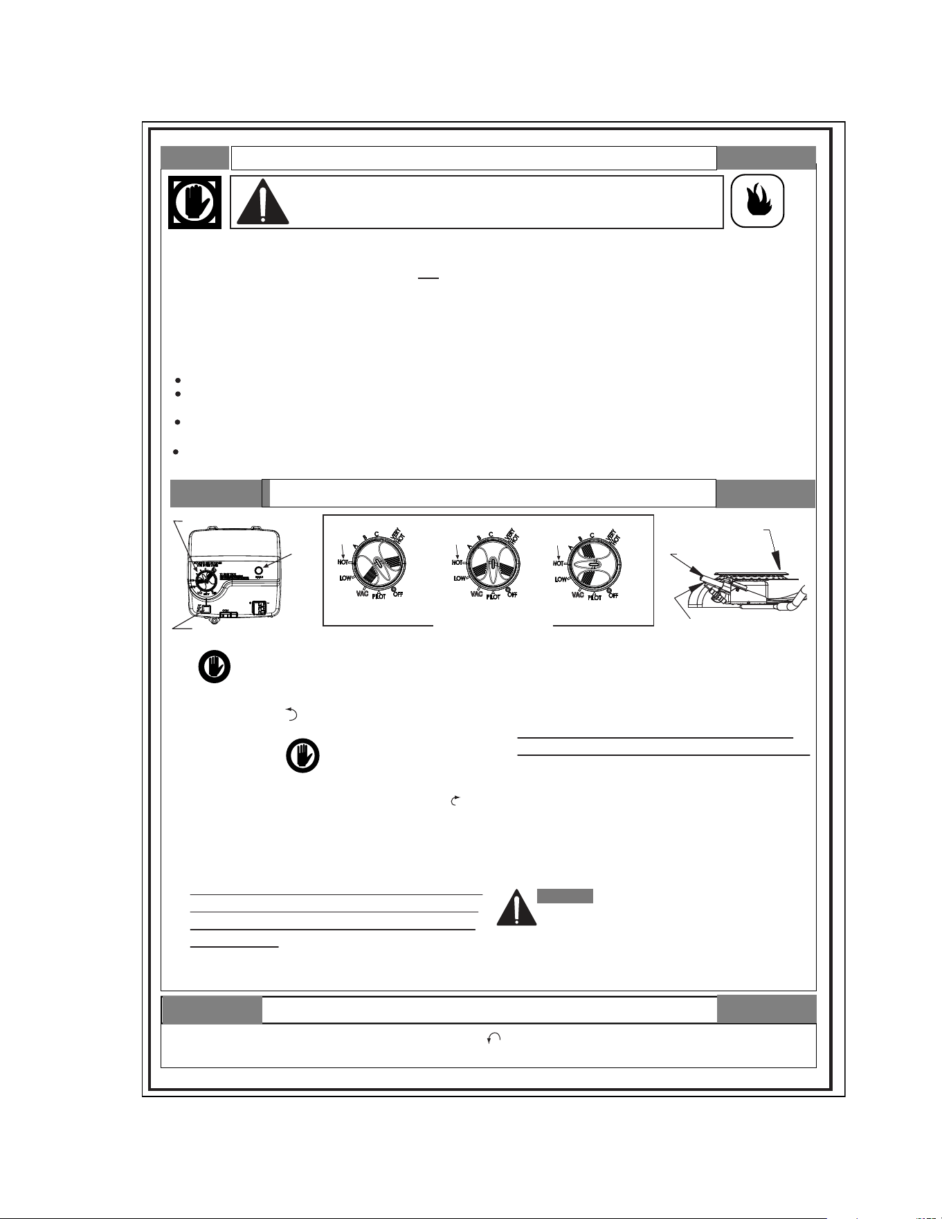
LIGHTING INSTRUCTIONS
CONTROL KNOB
FIGURE 'A'
"OFF" POSITION
FIGURE 'B'
"PILOT" POSITION
FIGURE 'C'
"ON" POSITION
TO TURN OFF GAS TO APPLIANCE
FIGURE 'D'
GAS CONTROL
MAIN BURNER
THERMOPILE
PILOT
1. STOP! It is imperative that you read all safety
warnings before lighting the pilot.
2. Turn the gas control/temperature knob
counterclockwise to the "OFF" setting.
3. Wait ten (10) minutes to clear out any gas. If you then
smell gas, STOP! Follow “ B” in the safety
information above on this label. If you do not
smell gas, go to the next step.
4. Turn the gas control/temperature knob clockwise to
“ PILOT”. See Figure ‘B’.
5. Press the gas control/temperature knob all the way
in and hold it in. The knob should travel in about
1/4 inch (6.35 mm) if it is set to "PILOT" correctly.
While holding the gas control/temperature knob in,
click the igniter button continuously (about once a
second) for up to 90 seconds or until Status Light
begins to blink.
6. When the status light starts blinking, release the
gas control/temperature knob. Set the gas control/
temperature knob to the desired setting. See Figure ‘C’.
If the status light does not start blinking within 90
seconds, repeat steps 2 through 5 up to THREE (3)
times, waiting 10 minutes between lighting attempts.
The circuitry in this advanced gas valve requires
that you wait 10 minutes between lighting attempts.
If the status light turns solid red, release the gas
control/temperature knob and repeat steps 2 through 5
(waiting 10 minutes before attempting to relight the pilot).
If the status light does not start blinking after three
lighting attempts, turn the gas control/temperature knob
to "OFF" and call a qualified service technician or your
gas supplier.
DANGER: Hotter water increases the risk of scald
injury. Consult the instruction manual before
changing temperature.
Refer to the Lighting Instructions in the Installation
Manual for more detailed troubleshooting
information.
1. Turn the gas control/temperature knob counterclockwise to the "OFF" setting. The status light will stop blinking and stay
on for a short time after the water heater is turned off. See Figure ‘A’.
VAC
Gas Control/Temperature Knob
Status
Light
Igniter
120°F
Mark
120°F
Mark
120°F
Mark
120°F
Mark
120°F
Mark
120°F
Mark
BEFORE LIGHTING: ENTIRE SYSTEM MUST BE FILLED WITH WATER AND AIR PURGED FROM ALL LINES
A.
C.
D.
B.
BEFORE LIGHTING
smell all around the appliance
area for gas. Be sure to smell next to the floor
because some gas is heavier than air and will
settle on the floor.
WHAT TO DO IF YOU SMELL GAS
Do not try to light any appliance.
Do not touch any electric switch; do not use any
phone in your building.
Immediately call your gas supplier from a neighbor's
phone. Follow the gas supplier's instructions.
If you cannot reach your gas supplier, call the fire
department.
Use only your hand to push in or turn the gas control
knob. Never use tools. If the knob will not push in or
turn by hand, don't try to repair it, call a qualified
service technician. Force or attempted repair may
result in a fire or explosion.
Do not use this appliance if any part has been under
water. Immediately contact a qualified installer or
service agency to replace a flooded water heater.
Do not attempt to repair the unit! It must be replaced!
This appliance has a pilot which is lit by a piezo-
electric spark gas ignition system. Do not open
the inner door of the appliance and try to light
the pilot by hand.
DO NOT USE THIS APPLIANCE IF THERE HAS
BEEN AN IGNITION OF VAPORS. Immediately
call a qualified service technician to inspect the
appliance. Water heaters subjected to a
flammable vapors ignition will show a
discoloration on the air intake grid and require
replacement of the entire water heater.
E.
24
Short repeated heating cycles caused by small hot water
uses can cause the temperature to exceed the thermostat
setting by up to 30°F (16.7°C). If you experience this
type of use you should consider using lower temperature
settings to reduce scald hazards.
Any water heater’s intended purpose is to heat water.
Hot water is needed for cleansing, cleaning, and
sanitizing (bodies, dishes, clothing). Untempered hot
water can present a scald hazard. Depending on the
time element, and the people involved (adults, children,
elderly, inrm, etc.) scalding may occur at different
temperatures.
HOTTER WATER CAN SCALD: Water heaters are
intended to produce hot water. Water heated to a
temperature which will satisfy space heating, clothes
washing, dish washing, and other sanitizing needs can
scald and permanently injure you upon contact. See
Table 3 (page 13).
Some people are more likely to be permanently injured by
hot water than others. These include the elderly, children,
the inrm, or physically/mentally handicapped. If anyone
using hot water in your home ts into one of these groups
or if there is a local code or state law requiring a certain
temperature water at the hot water tap, then you must
take special precautions. In addition to using the lowest
possible temperature setting that satises your hot water
needs, a means such as a mixing valve should be used
at the hot water taps used by these people or at the
water heater. Mixing valves are available at plumbing
supply or hardware stores, see Figure 11 (page 13) and
the piping diagram on page 41. Follow manufacturer’s
instructions for installation of the valves. Before changing
the factory setting on the thermostat, read this section
and see Figure 22.
WATER TEMPERATURE ADJUSTMENT
The water temperature setting can be adjusted from 55°F
to 181°F. Turn the Gas Control/Temperature Knob to the
desired setting/temperature.
NOTE:
The temperatures indicated are approximates. The actual
temperature of the heated water may vary.
STANDARD MODE
The controller adjusts the water heater to maintain the
temperature set by the user.
VACATION SETTING
The Vacation setting (VAC) sets the controller at
approximately 55°F. This setting is recommended when
the water heater is not in use for a long period of time.
This effectively turns the controller temperature setting
down to a temperature that prevents the water in the
water heater from freezing while still conserving energy.
STATUS LIGHT CODE
Normal Flashes:
• 0 Flashes Indicates Control Off/Pilot Out.
• 1 Flash Indicates Normal Operation.
• A solid red light indicates that the gas control
valve/thermostat is shutting down.
See Table 7 (page 36) for detailed diagnostic
information.
Never allow small children to use a hot water tap, or
to draw their own bath water. Never leave a child or
handicapped person unattended in a bathtub or shower.
NOTE: A water temperature range of 120°F-140°F
(49°C-60°C) is recommended by most dishwasher
manufacturers.
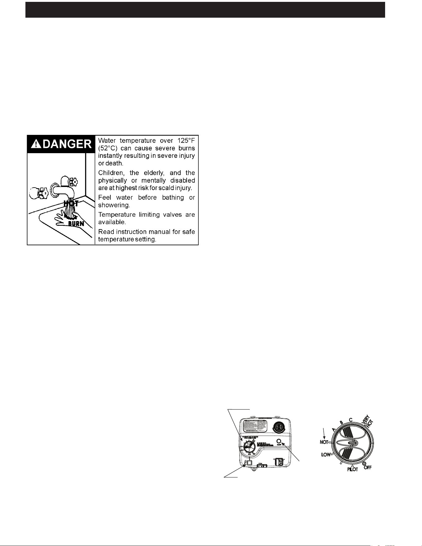
The thermostat is adjusted to the pilot position when it
is shipped from the factory. Water temperature can be
regulated by moving the temperature dial to the preferred
setting. The preferred starting point is 120°F at the “HOT”
setting. Align the knob with the desired water temperature
as shown in Figure 22. There is a hot water scald
potential if the thermostat is set too high.
If overheating occurs or the gas supply fails to shut off,
turn off the manual gas control valve to the water heater.
VAC
GAS CONTROL VALVE/THERMOSTAT
SETTINGS
GAS CONTROL/TEMPERATURE KNOB
120°F
MARK
STATUS
LIGHT
IGNITER
FIGURE 22. GAS CONTROL/TEMPERATURE KNOB
TEMPERATURE REGULATION

25
START-UP CONDITIONS
DRAFT HOOD OPERATION
Check draft hood operation by performing a worst case
depressurization of the building. With all doors and
windows closed, and with all air handling equipment and
exhaust fans operating such as furnaces, clothes dryers,
range hoods and bathroom fans, a match ame should
still be drawn into the draft hood of the water heater
with its burner ring. If the ame is not drawn toward the
draft hood, shut off water heater and make necessary air
supply changes to correct.
CONDENSATION
Whenever the water heater is lled with cold water, some
condensate will form while the burner is on. A water
heater may appear to be leaking when in fact the water is
condensation. This usually happens one of the following
occurs:
A. A new water heater is lled with cold water for the rst
time.
B. Burning gas produces water vapor in water heaters,
particularly high efciency models where ue temperatures
are lower.
C. Large amounts of hot water are used in a short time and
the rell water in the tank is very cold.
Moisture from the products of combustion condense on
the cooler tank surfaces and form drops of water which
may fall onto the burner or other hot surfaces to produce
a “sizzling” or “frying” noise.
Excessive condensation can cause pilot outage due to
water running down the ue tube onto the main burner
and putting out the pilot.
CHECKING GAS INPUT
With this heater in operation, determine whether it is
receiving the full rated input of gas. This may be done by
timing the gas meter and measuring gas pressure with a
gauge or manometer. When the heater is operating at full
capacity (full gas input) it should consume approximately
1 cubic foot of gas in the time shown in Table 5.
TABLE 6. INPUT CHECK TIME REQUIRED TO CONSUME 1
CU. FT. OF GAS
Model Type of Gas
BTU Per
Cu. Ft.
Approx. Time Required To
Consume 1 Cu. Ft. of Gas
75
Natural
Propane
1050
2500
50.3 sec. 119. 8 sec.
100
Natural
Propane
1050
2500
50.3 sec. 119.8 sec.
Use this formula to “clock” the meter. Be sure that other
gas consuming appliances are not operating during this
interval.
3,600 X H = Btu/Hr
T
T = Time in seconds needed to burn one
cubic foot of gas.
H = Heating value of gas in Btu’s per cubic foot of gas.
Btu/Hr = Actual heater input rate.
Example:
T = 50.3 seconds/ft3
H = 1,050 Btu/ft3 (natural gas)
Btu/Hr = ?
3,600 X 1,050 = 75,100 Btu/Hr (22.0 kW)
50.3
Compare the actual input rate to that given on the
heater’s rating plate. In the example, the full input rate
should be 75,100 Btu/Hr for natural gas.
Because of the suddenness and amount of water,
condensation water may be diagnosed as a “tank leak”.
After the water in the tank warms up (about 1-2 hours),
the condition should disappear.
Do not assume the water heater is leaking until there has
been enough time for the water in the tank to warm up.
An undersized water heater will cause more
condensation. The water heater must be sized properly
to meet the family’s demands for hot water including
dishwashers, washing machines and shower heads.
Excessive condensation may be noticed during the
winter and early spring months when incoming water
temperatures are at their lowest.
Good venting is essential for a gas red water heater
to operate properly as well as to carry away products of
combustion and water vapor.
FOR YOUR INFORMATION
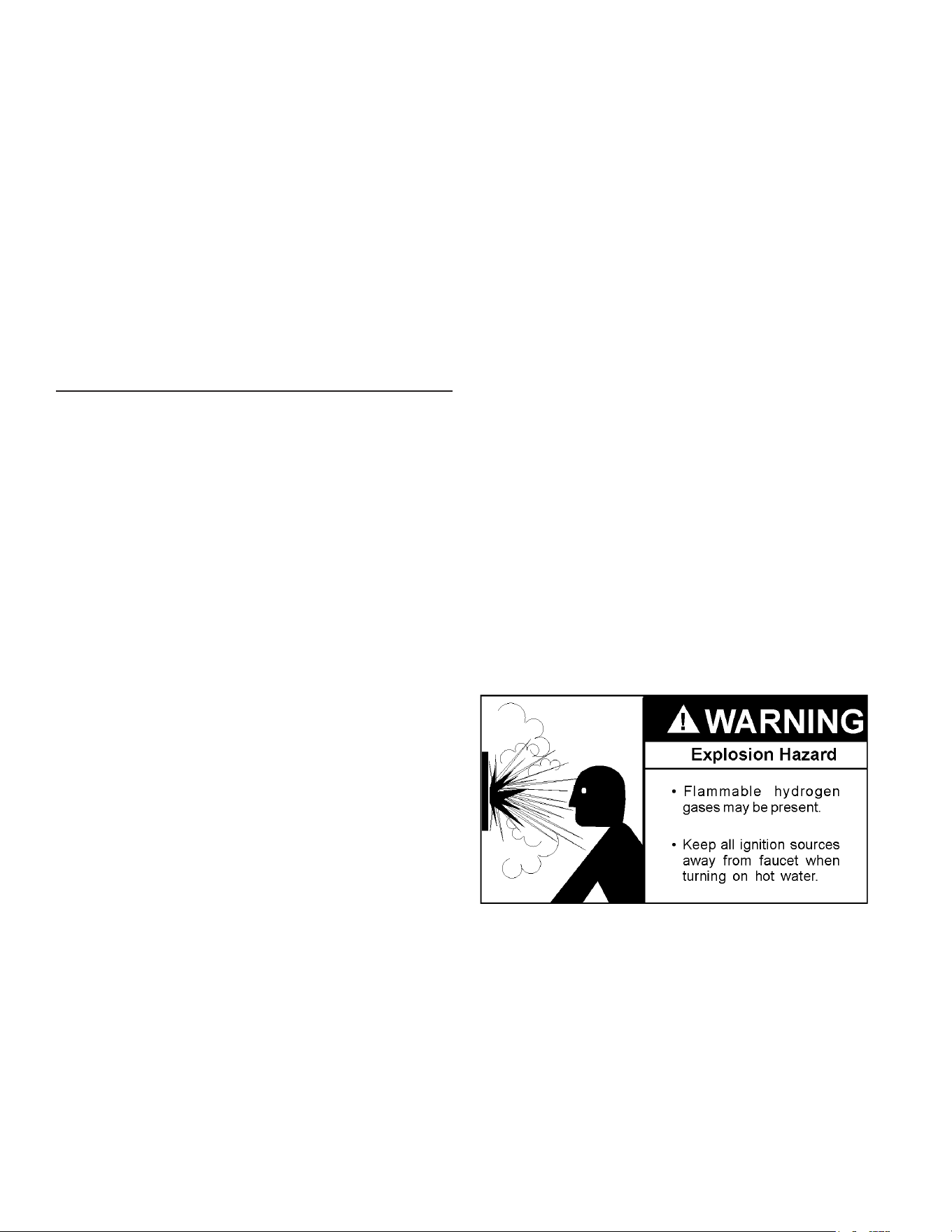
26
SMOKE/ODOR
It is not uncommon to experience a small amount of
smoke and odor during the initial start-up. This is due to
burning off of oil from metal parts, and will disappear in a
short while.
STRANGE SOUNDS
Possible noises due to expansion and contraction of
some metal parts during periods of heat-up and cool-
down do not necessarily represent harmful or dangerous
conditions.
Condensation causes sizzling and popping within the
burner area during heating and cooling periods and
should be considered normal. See Condensation (page
25).
OPERATIONAL CONDITIONS
SMELLY WATER
In each water heater there is installed at least one
anode rod (see parts section) for corrosion protection of
the tank. Certain water conditions will cause a reaction
between this rod and the water. The most common
complaint associated with the anode rod is one of a
“rotten egg smell” in the hot water. This odor is derived
from hydrogen sulde gas dissolved in the water. The
smell is the result of four factors which must all be
present for the odor to develop:
A. A concentration of sulfate in the supply water.
B. Little or no dissolved oxygen in the water.
C. A sulfate reducing bacteria which has accumulated within
the water heater (this harmless bacteria is nontoxic to
humans).
D. An excess of active hydrogen in the tank. This is caused
by the corrosion protective action of the anode.
Smelly water may be eliminated or reduced in some
water heater models by replacing the anode(s) with one
of less active material, and then chlorinating the water
heater tank and all hot water lines.
Contact the local water heater supplier or service agency
for further information concerning an Anode Replacement
Kit and this chlorination treatment.
If the smelly water persists after the anode replacement
and chlorination treatment, we can only suggest that
chlorination or aeration of the water supply be considered
to eliminate the water problem.
Do not remove the anode leaving the tank unprotected.
By doing so, all warranty on the water heater tank is
voided.
AIR IN HOT WATER FAUCETS
HYDROGEN GAS: Hydrogen gas can be produced in
a hot water system that has not been used for a long
period of time (generally two weeks or more). Hydrogen
gas is extremely ammable and explosive. To prevent
the possibility of injury under these conditions, we
recommend the hot water faucet, located farthest away,
be opened for several minutes before any electrical
appliances which are connected to the hot water system
are used (such as a dishwasher or washing machine).
If hydrogen gas is present, there will probably be an
unusual sound similar to air escaping through the pipe
as the hot water faucet is opened. There must be no
smoking or open ame near the faucet at the time it is
open.
TEMPERATURE-EXCEEDED SAFETY SHUT-OFF SYSTEM
This water heater is equipped with an automatic gas
Shut-off system. This system works when high water
temperatures are present. The high temperature Shut-off
is built into the gas control valve. It is non-resettable. If
the high temperature Shut-off activates, the gas control
valve must be replaced. Contact your gas supplier or
service agency. Turn “OFF” the entire gas supply to the
water heater.
See the 4-ash error code in Table 7 (page 36) for
troubleshooting.
27
VENTING SYSTEM INSPECTION
At least once a year a visual inspection should be made
of the venting system. You should look for:
1. Obstructions which could cause improper venting.
The combustion and ventilation air ow must not be
obstructed.
2. Damage or deterioration which could cause improper
venting or leakage of combustion products.
3. Rusted akes around top of water heater.
Be sure the vent piping is properly connected to prevent
escape of dangerous ue gases which could cause
deadly asphyxiation.
Obstructions and deteriorated vent systems may present
serious health risk or asphyxiation.
Chemical vapor corrosion of the ue and vent system
may occur if air for combustion contains certain chemical
vapors. Spray can propellants, cleaning solvents,
refrigerator and air conditioner refrigerants, swimming
pool chemicals, calcium and sodium chloride, waxes,
bleach and process chemicals are typical compounds
which are potentially corrosive.
If after inspection of vent system you found sooting or
deterioration, something is wrong. Call the local gas utility
to correct problem and clean or replace the ue and
venting before resuming operation of water heater.
Flood damage to a water heater may not be readily
visible or immediately detectable. However, over a period
of time a ooded water heater will create dangerous
conditions which can cause DEATH, SERIOUS BODILY
INJURY, OR PROPERTY DAMAGE. Contact a qualied
installer or service agency to replace a ooded water
heater. Do not attempt to repair the unit! It must be
replaced!
At least once a year a visual inspection should be made
of the main burner and pilot burner, see Figure 23. You
should check for sooting. Soot is not normal and will
impair proper combustion.
Soot build-up indicates a problem that requires correction
before further use. Turn OFF gas to water heater and
leave off until repairs are made, because failure to correct
the cause of the sooting can result in a re causing
death, serious injury, or property damage.
FIGURE 23. GAS BURNER ASSEMBLY
BURNER CLEANING
If inspection of the burner shows that cleaning is
required, turn the gas control knob clockwise ( ) to the
OFF position, depressing slightly.
NOTE: The knob cannot be turned from PILOT to OFF
unless knob is depressed slightly. DO NOT FORCE.
Loose deposits on or around the burner can be removed
by carefully using the hose of a vacuum cleaner inserted
through the access door of the water heater. If the
burner needs to be removed for additional cleaning,
call a service agency to remove and clean the burner
and correct the problem that required the burner to be
cleaned.
PERIODIC MAINTENANCE
BURNER INSPECTION
28
AIR SHUTTER ADJUSTMENT
If the installation is at a high elevation and the burner
ame exhibits ame lifting and/or noise, do the following:
1. Use a screw driver to loosen the air shutter screw.
2. Adjust the air shutter by rotating the shutter. Counter
clockwise to close and Clockwise to open.
a. Close air shutter - to prevent noisy ames that are
lifting from the burner ports.
b. Open air shutter – to reduce yellow tipping of the
ame. (A small number of yellow tips can be normal
to LP gases.)
3. Tighten the air shutter screw to secure the air shutter.
See Adjusting Air Shutter for Higher Altitudes (page
9).
HOUSEKEEPING
Fire and Explosion Hazard
Do not obstruct combustion air
openings at the bottom of the
water heater.
Do not use or store flammable vapor
products such as gasoline, solvents
or adhesives in the same room or area
near water heater or other appliance.
Can cause serious injury or death.
Vacuum around base of water heater for dust, dirt, and
lint on a regular basis.
INSTALLED IN SUITABLE AREA: To insure sufcient
ventilation and combustion air supply, proper clearances
from the water heater must be maintained. See Facts to
Consider About the Location (page 7). Combustible
materials such as clothing, cleaning materials, or
ammable liquids, etc. must not be placed against or
adjacent to the water heater which can cause a re.
ANODE ROD INSPECTION
Property Damage Hazard
•
Avoid water heater damage.
•
Inspection and replacement of anode rod required.
CAUTION
The anode rod is used to protect the tank from corrosion.
Most hot water tanks are equipped with an anode rod.
The submerged rod sacrices itself to protect the tank.
Instead of corroding the tank, water ions attack and eat
away the anode rod. This does not affect water’s taste
or color. The rod must be maintained to keep the tank in
operating condition.
Anode deterioration depends on water conductivity, not
necessarily water condition. A corroded or pitted anode
rod indicates high water conductivity and should be
checked and/or replaced more often than an anode rod
that appears to be intact. Replacement of a depleted
anode rod can extend the life of your water heater.
Inspection should be conducted by a qualied service
agency, and at a minimum should be checked annually
after the warranty period.
Articially softened water is exceedingly corrosive
because the process substitutes sodium ions for
magnesium and calcium ions.
The use of a water softener may decrease the life of the
water heater tank.
The anode rod should be inspected after a maximum of
three years and annually thereafter until the condition of
the anode rod dictates its replacement.
NOTE: Articially softened water requires the anode rod
to be inspected annually.
TEMPERATURE-PRESSURE RELIEF VALVE TEST
Burn hazard.
Hot water discharge.
Keep clear of Temperature-
Pressure Relief Valve
discharge outlet.
It is recommended that the temperature-pressure relief
valve should be checked to ensure that it is in operating
condition every 6 months.
When checking the temperature-pressure relief valve
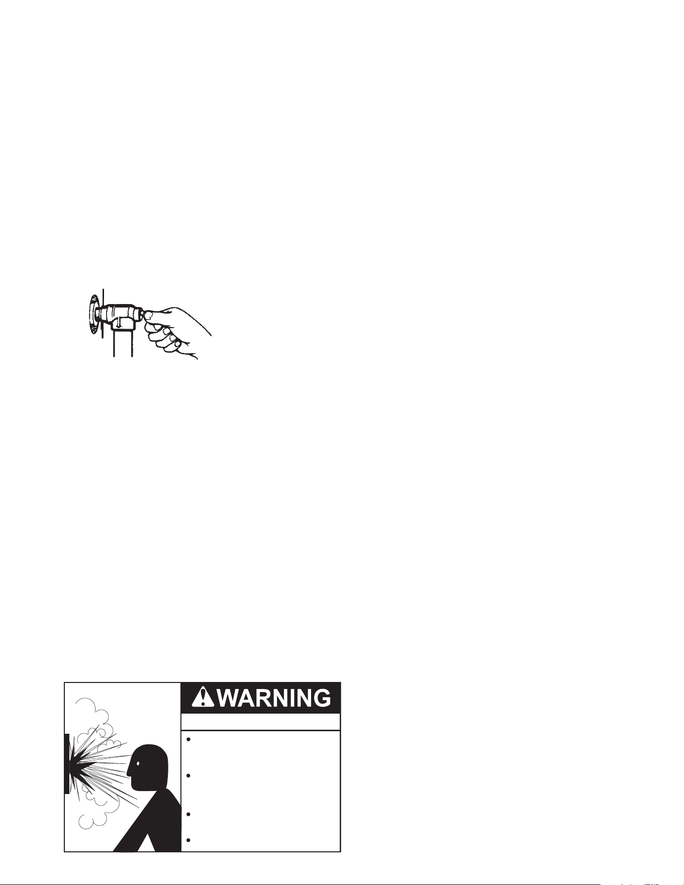
29
operation, make sure that (1) no one is in front of or
around the outlet of the temperature-pressure relief
valve discharge line, and (2) that the water discharge
will not cause any property damage, as the water may
be extremely hot. Use care when operating valve as the
valve may be hot.
To check the relief valve, lift the lever at the end of the
valve several times, see Figure 24. The valve should seat
properly and operate freely.
If after manually operating the valve, it fails to completely
reset and continues to release water, immediately close
the cold water inlet to the water heater and drain the
water heater, see Draining and Flushing (page 32).
Replace the temperature-pressure relief valve with a
properly rated/sized new one, see Temperature-Pressure
Relief Valve (page 14) for information on replacement.
DISCHARGE PIPE
TEMPERATURE-PRESSURE
RELIEF VALVE
FIGURE 24. CHECKING THE RELIEF VALVE
If the temperature-pressure relief valve on the water
heater weeps or discharges periodically, this may be due
to thermal expansion.
NOTE: Excessive water pressure is the most common
cause of temperature-pressure relief valve leakage.
Excessive water system pressure is most often caused
by thermal expansion in a “closed system.” See Closed
Water Systems (page 13) and Thermal Expansion
(page 13). The temperature-pressure relief valve is not
intended for the constant relief of thermal expansion.
Temperature-pressure relief valve leakage due to
pressure build up in a closed system that does not have
a thermal expansion tank installed is not covered under
the limited warranty. Thermal expansion tanks must be
installed on all closed water systems.
DO NOT PLUG THE TEMPERATURE-PRESSURE
RELIEF VALVE OPENING. THIS CAN CAUSE
PROPERTY DAMAGE, SERIOUS INJURY OR DEATH.
Explosion Hazard
Temperature-Pressure Relief Valve
must comply with ANSI Z21.22-
CSA 4.4 and ASME code.
Properly sized temperature-
pressure relief valve must be
installed in opening provided.
Can result in overheating and
excessive tank pressure.
Can cause serious injury or death.
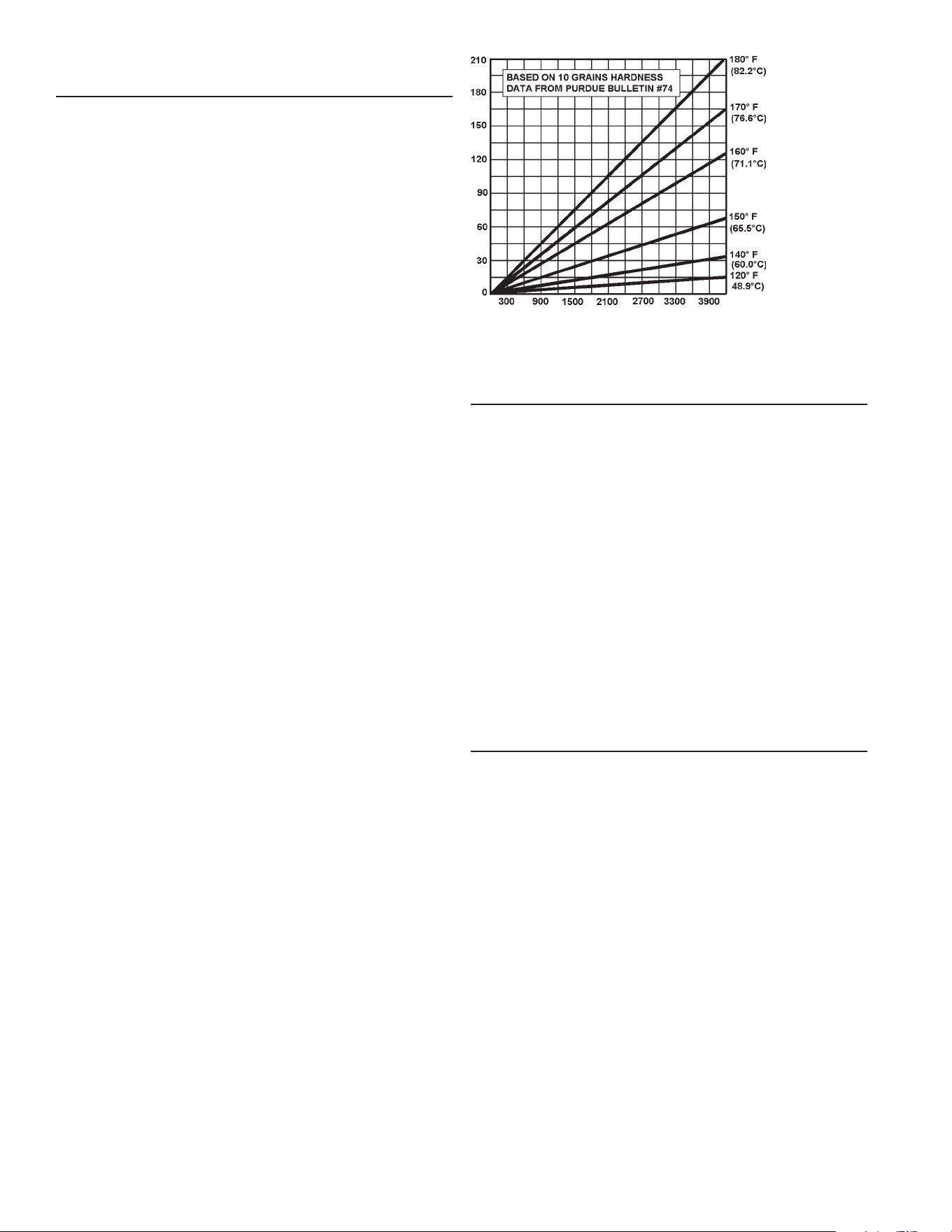
30
PERIODIC REMOVAL OF LIME DEPOSITS FROM
TANK TYPE COMMERCIAL WATER HEATERS
The amount of calcium carbonate (lime) released from
water is in direct proportion to water temperature and
usage, see the chart (Figure 25). The higher the water
temperature or water usage, the more lime deposits are
dropped out of the water. This is the lime scale which
forms in pipes, heaters and on cooking utensils.
Lime accumulation not only reduces the life of the
equipment but also reduces efciency of the heater and
increases fuel consumption.
The usage of water softening equipment greatly reduces
the hardness of the water. However, this equipment does
not always remove all of the hardness (lime). For this
reason it is recommended that a regular schedule for
deliming be maintained.
The time between cleaning will vary from weeks to
months depending upon water conditions and usage.
The depth of lime buildup should be measured
periodically. Heaters equipped with cleanout openings
will have about 2” of lime buildup when the level of lime
has reached the bottom of the cleanout opening. A
schedule for deliming should then be set up,based on the
amount of time it would take for a 1” buildup of lime. It is
recommended that the water heater initially be inspected
after 6 months.
EXAMPLE 1:
Initial inspection after 6 months shows 1/2” of lime
accumulation. Therefore, the heater should be delimed
once a year.
EXAMPLE 2:
Initial inspection after 6 months shows 2” of lime
accumulation.
Therefore, the heater should be delimed every 3 months.
FIGURE 25. LIME BUILD-UP BY TEMPERATURE AND
USAGE
DELIMING SOLVENTS
UN•LIME is recommended for deliming. UN•LIME is a
patented food grade acid which is safe to handle and
does not create the harmful fumes which are associated
with other products.
UN•LIME may be obtained from your dealer, distributor
or water heater manufacturer. Order Part Number
100110459, 1 gallon, packed 4 gallons per case or Part
Number 100110460, 5-gallon container.
NOTE: Un•Lime is not available for use in Canada.
Hydrochloric base acids are not recommended for use on
glass lined tanks.
Observe handling instructions on label of product being
used.
TANK CLEANOUT PROCEDURE
The following practices will ensure longer life and enable
the unit to operate at its designed efciency:
1. Once a month the heater should be ushed. Open
the drain valve and allow two gallons of water to drain
from the heater. Inlet water valve should remain open
to maintain pressure in tank.
2. A cleanout opening is provided for periodic cleaning
of the tank. Gas must be shut off and heater drained
before opening cleanout.
3. To clean heater through cleanout opening, proceed as
follows:
a. Drain heater.
b. Remove outer cover plate from lower side of heater
jacket.
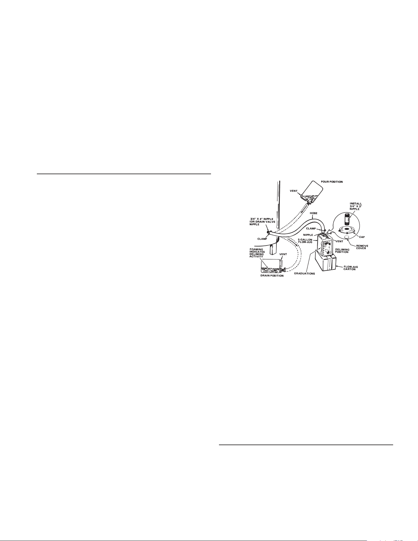
31
c. Remove six (6) hex head screws securing tank
cleanout plate and remove plate.
d. Remove lime, scale, or sediment using care not to
damage the glass lining.
e. Inspect cleanout plate gasket, if new gasket is
required, see the replacement parts list for item
number.
f. Install cleanout plate. Be sure to draw plate up tight
by tightening screws securely.
g. Replace outer jacket cover plate.
h. In some water areas the sediment might not be
removed by this method and may result in the
water heater making rumbling or boiling noises. To
dissolve and remove these more stubborn mineral
deposits, UN•LIME Professional Delimer should be
used.
DELIMING USING FLO-JUG METHOD
UN•LIME in the 5 gallon size is recommended for
deliming this water heater. UN•LIME with the necessary
hoses and ttings to delime your heater is also available
as a kit: Up-N-Down Transfer Kit. Contact your local
dealer, distributor or water heater manufacturer.
PREPARE THE WATER HEATER
To delime the water heater using the Flo-jug method, rst
prepare the heater for deliming.
PREPARE THE UP-N-DOWN TRANSFER KIT
The next step is the preparation on the Up-N-Down
Transfer Kit, if you have not already done so:
1. With the 5 gallon Up-N-Down container in the vertical
position, unscrew the plastic vent cap in the handle
and pierce the plastic membrane over the vent boss
under the cap to allow the container to vent.
Note: If your container does not have the vent cap and
vent boss, drill a 3/16” (4.76 mm) hole in the handle.
When you have nished deliming you will be able to
plug this drilled vent with the stainless steel screw that
is supplied with the kit.
2. Remove the container’s cap and cut plastic membrane
located in the 3/4” IPT opening in cap. Take care to not
damage the threads.
3. Find the 3/4” male adapter, apply teon tape to the
threaded end and screw it into the 3/4” IPT opening in
the cap.
4. Put cap with male adapter back on the container and
slide 3/4” hose over end of male adapter and fasten in
place using hose clamp provided.
DELIME USING FLO-JUG METHOD
1. Slide the hose clamp over end of hose and slide
hose over the male adapter in the water heater drain
opening and secure in place using hose clamp.
2. Lift container to the “Pour” Position being careful to
keep the vent in the handle above the liquid level and
pour the UN•LIME into the heater.
3. Lower container, you may have to place the container
on its empty carton to prevent the UN•LIME from
owing back into the container.
4. Let UN•LIME remain in the heater for 5 minutes and
then lower the container to the “Drain” Position.
5. Deliming activity is indicated by foaming on the
surface of the UN•LIME. If there is deliming activity,
repeat steps 6 thru 8.
FIGURE 26. DELIMING KIT CONFIGURATION
Normally, lime removal will be completed within one hour.
Severe build-up of lime may take longer than an hour to
complete descaling.
Note: To check UN•LIME for continued use, place some
scale or white chalk in a glass with a small amount of
UN•LIME. If the material is vigorously dissolved by the
UN•LIME, it can be reused; if not, the UN•LIME should be
replaced.
If the temperature-pressure relief valve on the appliance
weeps or discharges periodically, this may be due to
thermal expansion. You may have a check valve installed
in the water line or a water meter with a check valve.
Consult your local water supplier or service agency for
further information. Do not plug the temperature-pressure
relief valve.
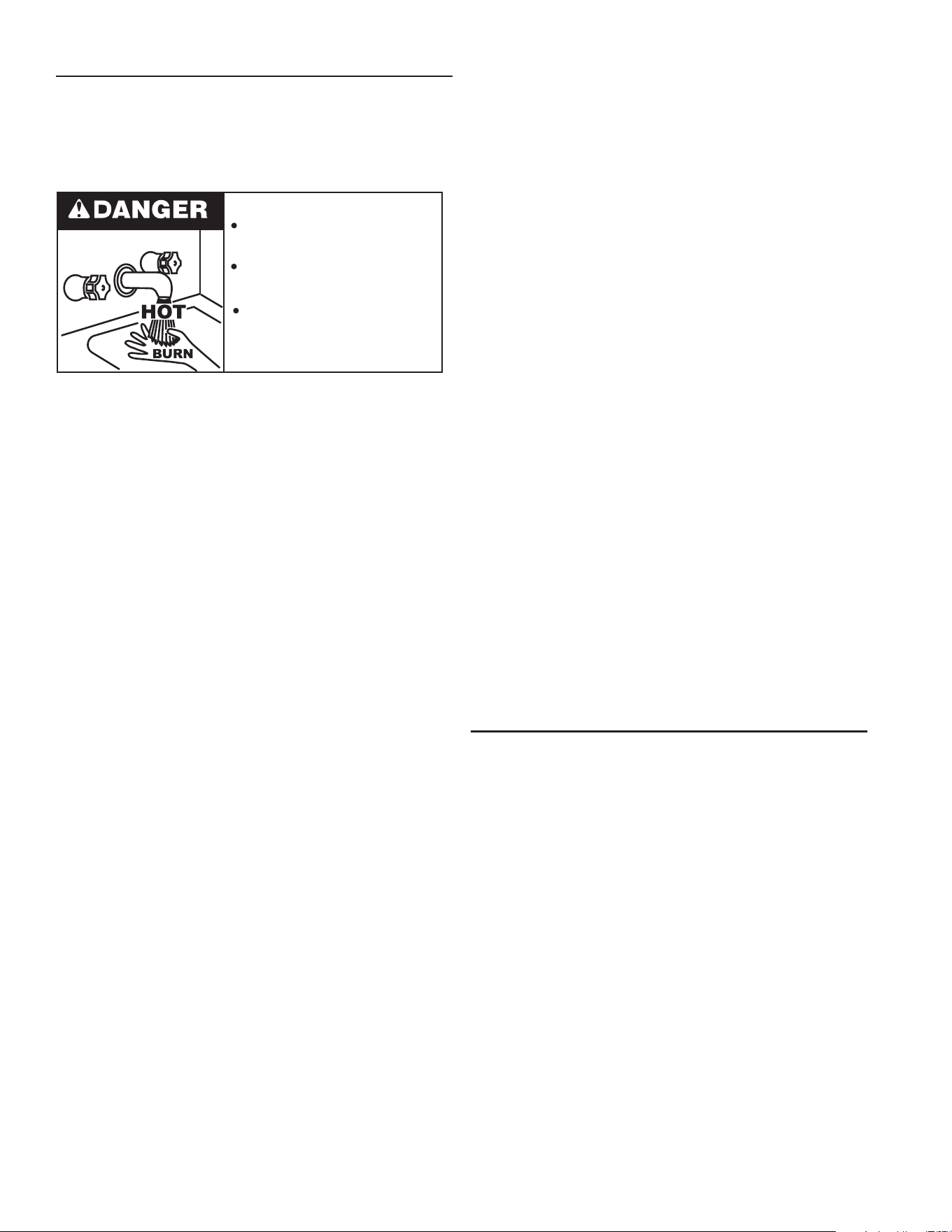
32
DRAINING AND FLUSHING
It is recommended that the water heater storage tank be
drained and ushed every 6 months to reduce sediment
buildup. The water heater should be drained if being shut
down during freezing temperatures. See Figure 29 for the
location of the water heater components described below.
Burn harzard.
Hot water discharge.
Keep hands clear of drain
valve discharge.
TO DRAIN THE WATER HEATER STORAGE TANK:
1. Turn off the gas supply at the Main Gas Shutoff Valve
if the water heater is going to be shut down for an
extended period.
2. Ensure the cold water inlet valve is open.
3. Open a nearby hot water faucet and let the water run
until the water is no longer hot.
4. Close the cold water inlet valve to the water heater.
5. Connect a hose to the water heater drain valve and
terminate it to an adequate drain.
6. Open the water heater drain valve and allow all the
water to drain from the storage tank.
7. Close the water heater drain valve when all water in
the storage tank has drained.
8. Close the hot water faucet opened in Step 4.
9. If the water heater is going to be shut down for an
extended period, the drain valve should be left open.
TO FLUSH THE WATER HEATER STORAGE TANK:
1. Ensure the cold water inlet valve is open.
2. Open a nearby hot water faucet and let the water run
until the water is no longer hot. Then close the hot
water faucet.
3. Connect a hose to the drain valve and terminate it to
an adequate drain.
4. Ensure the drain hose is secured before and during
the entire ushing procedure. Flushing is performed
with system water pressure applied to the water
heater.
5. Open the water heater drain valve to ush the storage
tank.
6. Flush the water heater storage tank to remove
sediment and allow the water to ow until it runs clean.
7. Close the water heater drain valve when ushing is
completed.
8. Remove the drain hose.
9. Fill the water heater - see Filling the Water Heater
(page 15) .
10. Turn on the gas supply to the water heater at the Main
Gas Shutoff Valve.
11. Allow the water heater to complete several heating
cycles to ensure it is operating properly.
SERVICE
Before calling for repair service, read the “Start Up
Conditions” and “Operational Conditions” found in the
“For Your Information” section of this manual.
If a condition persists or you are uncertain about the
operation of the water heater contact a service agency.
If you are not thoroughly familiar with gas codes, your
water heater, and safety practices, contact your gas
supplier or qualied installer to check the water heater.
Use the ”Leakage Checkpoints” guide to check a
“leaking” water heater. Many suspected leaks are not
leaking tanks. Often the source of the water can be found
and corrected.
Read this manual rst. Then before checking the water
heater make sure the gas supply has been turned OFF,
and never turn the gas ON before the tank is completely
full of water.
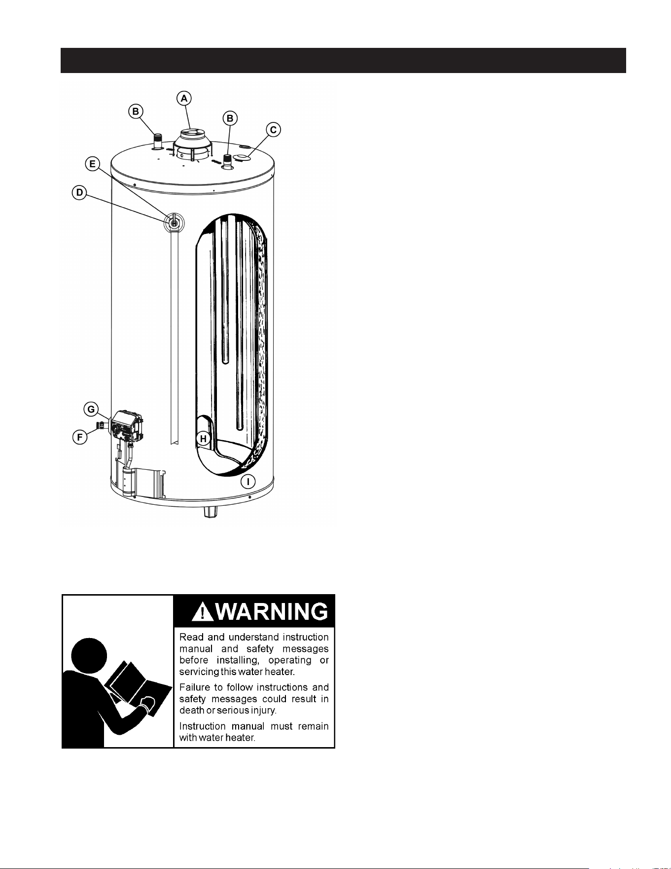
33
A. Water at the draft hood is water vapor which has
condensed out of the combustion products. This is caused
by a problem in the vent. Contact the gas utility.
B. *Condensation may be seen on pipes in humid weather
or pipe connections may be leaking.
C. *The anode rod tting may be leaking.
D. Small amounts of water from temperature-pressure relief
valve may be due to thermal expansion or high water
pressure in your area.
E. *The temperature-pressure relief valve may be leaking at
the tank tting.
F. Water from a drain valve may be due to the valve being
slightly opened.
G. *The drain valve may be leaking at the tank tting.
H. Combustion products contain water vapor which can
condense on the cooler surfaces of the tank. Droplets
form and drip onto the burner or run on the oor. This is
common at the time of start-up after installation and when
incoming water is cold.
I. Water in the water heater bottom or on the oor may be
from condensation, loose connections, or the relief valve.
DO NOT replace the water heater until a full inspection
of all possible water sources is made and necessary
corrective steps taken.
*To check where threaded portion enters tank, insert cotton
swab between jacket opening and tting. If cotton is wet,
follow the instructions in Draining and Flushing (page 32)
and then remove tting. Put pipe dope or teon tape on the
threads and replace. Then follow the instructions in Filling
the Water Heater (page 15).
LEAKAGE TEST POINTS
FIGURE 29. WATER HEATER COMPONENTS
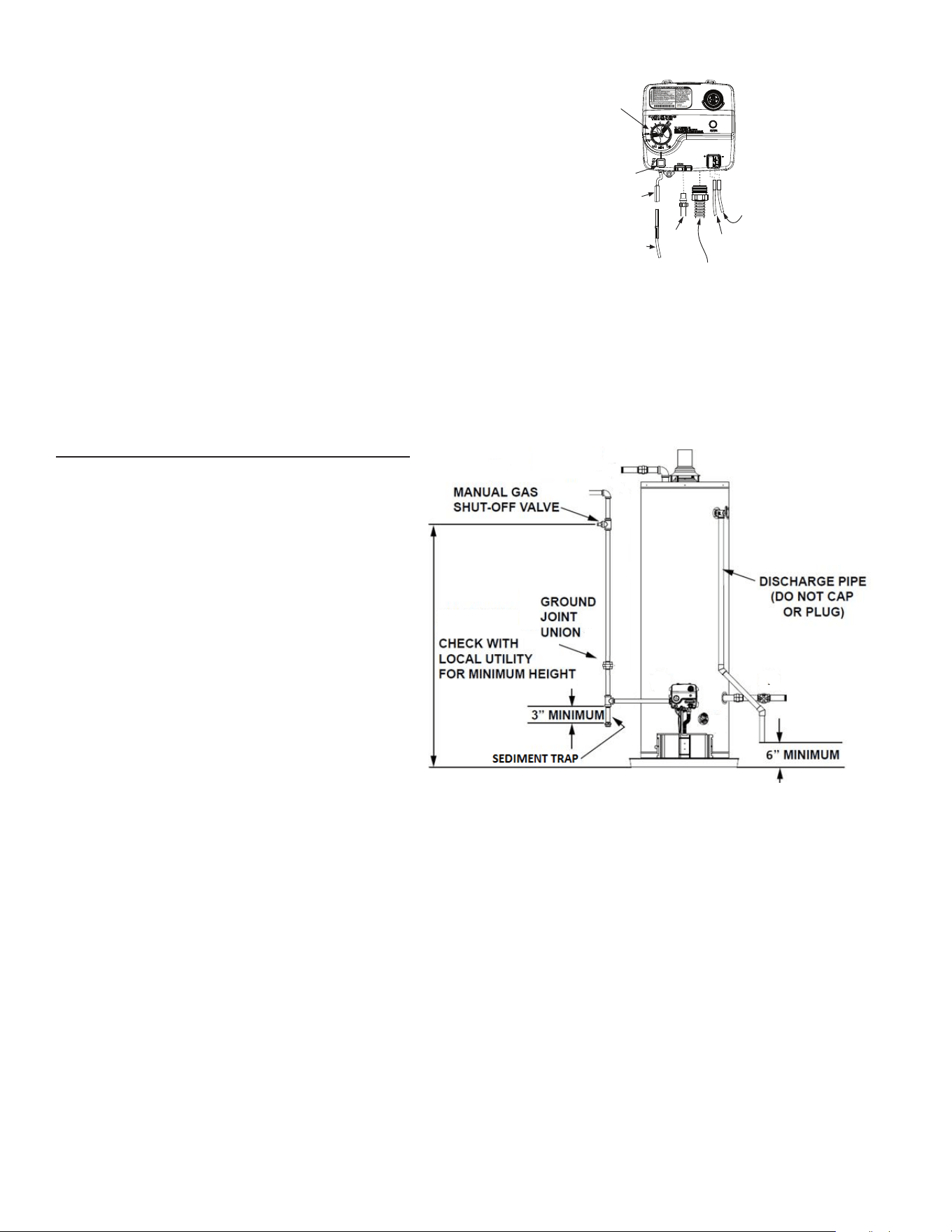
34
Never use this water heater unless it is completely
lled with water. To prevent damage to the tank,
the tank must
be lled with water. Water must ow
from the hot water faucet before turning “ON” gas
to the water heater.
Read this manual rst. Then before checking the
water heater make sure the gas supply has been
turned “OFF”, and never turn the gas “ON” before
the tank is completely full of water.
Never use this water heater unless it is completely
lled with water. To prevent damage to the tank,
the tank must be lled with water. Water must ow
from the hot water faucet before turning “ON” gas
to the water heater.
Leakage from other appliances, water lines, or
ground seepage should also be checked.
REMOVING AND REPLACING THE GAS CON-
TROL VALVE/THERMOSTAT
IMPORTANT: This water heater has a resettable
thermal switch installed. Do not attempt to disable
or modify this feature in any way. Use only factory
authorized replacement parts. IMPORTANT: This
gas control valve/thermostat is shipped from
the factory as a natural gas unit. However,
it may be converted to use LP gas. Before
installing this gas control valve/ thermostat,
make sure that it is congured for the type of
gas that you are using.
REMOVING THE GAS CONTROL VALVE/THERMOSTAT:
1. Turn the gas control/temperature knob to the
OFF position. See Figure 22 (page 24).
2. Turn off the gas at the manual shut-off valve on
the gas supply pipe.
3. Drain the water heater. Follow the instructions in
Draining and Flushing (page 32).
4. Disconnect the igniter wire from the igniter lead
wire. Use needle nose pliers to disconnect
the red (+) and white (-) thermopile wires.
Disconnect the pilot tube (7/16” wrench) and
manifold tube (3/4” wrench) at the gas control
valve/thermostat. See Gas Control Valve
Removal (page 34).
IGNITER
WIRE
RED WIRE
(LEFT SIDE)
PILOT
TUBE
MANIFOLD TUBE
IGNITER
BUTTON
IGNITER
LEAD
WIRE
WHITE
WIRE
(RIGHT
SIDE)
GAS CONTROL/
TEMPERATURE KNOB
VAC
FIGURE 27. GAS CONTROL VALVE REMOVAL
5. Referring to Figure 28 (page 34), disconnect the ground
joint union in the gas piping.
6. Disconnect the remaining pipe from the gas control valve/
thermostat.
FIGURE 28. PIPING CONFIGURATION
7. To remove the gas control valve/thermostat, thread a 4”
section of gas pipe into the gas inlet and use it to turn the
gas control valve/thermostat (counterclockwise.) Do not
use a pipe wrench or equivalent to grip body. Damage may
result, causing leaks. Do not insert any sharp objects into
the inlet or outlet connections. Damage to the gas control
valve/thermostat may result.

35
REPLACING THE GAS CONTROL VALVE/THERMOSTAT:
1. To replace the gas control valve/thermostat, reassemble
in reverse order. When replacing the gas control valve/
thermostat, thread a 4” section of gas pipe into the
inlet and use it to turn the gas control valve/thermostat
(clockwise). DO NOT OVER TIGHTEN; damage may
result.
2. Be sure to use approved Teon® tape or pipe joint
compound on the gas piping connections and tting on
the back of the gas control valve that screws into the
tank.
3. Be sure to remove the pilot ferrule nut from the new gas
control valve/thermostat.
4. Turn the main gas supply on and check the gas supply
connections for leaks. Correct any leak found. Next,
light the pilot and main burner, then check the manifold
tube and pilot tube connections for leaks. Correct
any leak found. Use an approved noncorrosive leak
detection solution. If such a solution is not available, use
a mixture of hand dish washing soap and water (one
part soap to 15 parts water) or childrens’ soap bubble
solution. Bubbles forming indicate a leak.
Be sure tank is completely lled with water before lighting
and activating the water heater. Follow the Lighting
Instructions on the front of the water heater.
TEFLON® is a registered trademark of E.I. Du Pont De
Nemours and Company.

36
TABLE 7. STATUS LIGHT AND DIAGNOSTIC CODE TROUBLESHOOTING CHART
LED Status Problem Corrective Action
0 FLASHES (LED NOT LIT) Pilot light is not lit or Thermopile has not yet
reached normal operating temperature.
Turn Gas Control Valve/Thermostat knob to OFF. Wait
10 minutes, then attempt to relight Pilot by following the
lighting instructions on the water heater’s label. Until
the Thermopile reaches its normal operating tempera-
ture, the Status Light will not blink, even if the Pilot is lit.
It may take up to 90 seconds of continuous Pilot opera-
tion before the Thermopile reaches normal operating
temperature and the Status Light starts to blink.
If the Status Light does not blink after three lighting at-
tempts, check to make sure unit is getting gas. Remove
the outer door. Press reset button. Replace outer door.
Turn Gas Control Valve/Thermostat knob to OFF. Wait
10 minutes, then attempt to light Pilot by following the
lighting instructions on the water heater’s label. Look
through the view port for the Pilot ame. If Pilot is
not visible, the spark igniter or gas supply to the Pilot
should be checked.
If the Pilot is visible and the Status Light does not blink
after 90 seconds of continuous Pilot operation, the Pilot
ame may not be heating the Thermopile sufciently
(weak Pilot), the Thermopile may be defective, or wiring
connectors may be loose.
NOTE: If the water heater has been operating but has
stopped and will not re-light, check the ame-arrestor
for signs of high temperature (blue or black) discolor-
ation indicating a ammable vapor incident. If you sus-
pect a ammable vapor incident has occurred, do not
use this appliance. Immediately call a qualied techni-
cian to inspect the appliance. Water heaters subjected
to a ammable vapors ignition will require replacement
of the entire water heater.
LIGHT ON (SOLID) Pilot light was recently extinguished and the
Thermopile is cooling down.
Turn Gas Control Valve/Thermostat knob to OFF. Wait
10 minutes for the Thermopile to cool, then attempt to
relight Pilot by following the lighting instructions on the
water heater’s label. NOTE: This gas control valve/
thermostat has built-in circuitry that requires waiting 10
minutes between lighting attempts.
Until the Thermopile reaches its normal operating tem-
perature, the Status Light will not blink, even if the Pilot
is lit. It may take up to 90 seconds of continuous Pilot
operation before the Thermopile reaches normal oper-
ating temperature and the Status Light starts to blink
1 FLASH (EVERY 3 SECONDS) Normal Operation No corrective action necessary.
2 FLASHES Pilot is lit but the Thermopile is not producing
the required output voltage.
Turn Gas Control Valve/Thermostat knob to OFF. The
Thermopile is probably defective, but loose wiring
connections or a weak Pilot ame can also cause this
symptom.
4 FLASHES The Gas Control Valve’s temperature sensor
has detected that the water temperature was
too high. Once this condition occurs, the
Main Burner and the Pilot Light will be shut
off. Since the Pilot light will be off, should this
condition occur, this Flash Code will only be
displayed immediately after the Pilot has been
relit. Turn Gas Control Valve/Thermostat knob
to OFF.
Relight pilot and verify 4 ashes. If 4 ashes are
observed, turn Gas Control Valve/Thermostat knob to
OFF. Turn Main Gas Supply OFF. Replace the Gas
Control Valve/Thermostat. See Removing and Replac-
ing the Gas Control Valve/Thermostat (page 34).
37
TABLE 7. STATUS LIGHT AND DIAGNOSTIC CODE TROUBLESHOOTING CHART
LED Status Problem Corrective Action
5 FLASHES The temperature sensor (thermistor) is defec-
tive.
Turn Gas Control Valve/Thermostat knob to OFF. Turn
Main Gas Supply OFF. Replace the Gas Control Valve/
Thermostat. See Removing and Replacing the Gas
Control Valve/Thermostat (page 34).
7 FLASHES Gas Control Valve failure. Turn Gas Control Valve/Thermostat knob to OFF. Turn
Main Gas Supply OFF. Replace the Gas Control Valve/
Thermostat. See Removing and Replacing the Gas
Control Valve/Thermostat (page 34).
8 FLASHES This condition only appears if the gas control/
temperature knob has been turned off and the
thermopile continued to produce electric pow-
er. This condition can occur if the thermopile
does not cool down as quickly as expected
when the unit is shut off. This condition can
also occur if the gas control/temperature knob
has been turned off and the pilot continues to
operate because the pilot valve is stuck in the
open position.
Make sure that the gas control valve/thermostat knob
is set to OFF. Wait one minute. Remove the outer door.
Look through the sight glass for a pilot ame. If a pilot
ame is observed with the gas control valve/thermostat
knob set to the OFF position, the pilot valve is stuck
open. Turn the main gas supply OFF. Replace the gas
control valve/thermostat. For instructions, see Remov-
ing and Replacing the Gas Control Valve/Thermo-
stat (page 34).
If the pilot ame is not observed when the gas control
valve/thermostat knob is set to the OFF position, wait
10 minutes for the thermopile to cool, then attempt to
relight the pilot by following the lighting instructions on
the water heater’s label. If this condition returns, re-
place the gas control valve/thermostat. See Removing
and Replacing the Gas Control Valve/Thermostat
(page 34).
38
TABLE 8. GENERAL TROUBLESHOOTING GUIDELINES
These guidelines should be used by a qualied service agent.
Symptom Problem Corrective Action
WATER LEAKS
Improperly sealed, hot or cold supply connection, relief
valve, drain valve, or thermostat threads.
Tighten threaded connections.
Leakage from other appliances or water lines. Inspect other appliances near water heater.
Condensation of ue products. See Condensation (page 25).
LEAKING T&P VALVE
Thermal expansion in closed water system. Install thermal expansion tank (DO NOT plug T&P valve).
Improperly seated valve.
Check relief valve for proper operation (DO NOT plug T&P
valve).
SMELLY WATER
High sulfate or mineral content in water supply. Drain and ush heater thoroughly, then rell.
Bacteria in water supply. Chlorinate or aerate water supply.
PILOT WILL NOT LIGHT
Gas control knob not positioned correctly. See the Lighting Instructions on the water heater’s label.
Main gas supply off. Turn on main gas shutoff valve.
Thermopile malfunction. Replace pilot/thermopile assembly.
No spark. Locate piezo switch on thermostat. Replace if needed.
BURNER WILL NOT STAY
LIT
Thermopile malfunction. Replace pilot/thermopile assembly.
Defective Gas Control. Replace Gas Control.
PILOT OUTAGE
Dirty pilot burner. Clean pilot assembly.
Thermopile malfunction. Replace pilot/thermopile assembly.
Defective Gas Control. Replace Gas Control.
Thermopile tip is not in contact with pilot ame. Insert thermopile correctly.
NOT ENOUGH HOT
WATER
Heater not lit or thermostat not on. See Lighting Instructions on the water heater’s label.
Thermostat set too low. See Temperature Regulation (page 24).
Heater undersized. Reduce hot water use.
Low gas pressure. Contact your gas supplier.
Incoming water is unusually cold. Allow more time for heater to re-heat.
Leaking hot water pipes or xtures. Have plumber check and repair leaks.
High temperature limit switch activated. Contact a service agency to determine cause.
WATER TOO HOT Thermostat set too high. See Temperature Regulation (page 24).
WATER HEATER
SOUNDS
Condensation dripping on burner. See Condensation (page 25).
SIZZLING OR RUMBLING Sediment or calcium in bottom of heater tank.
Clean sediment from tank. See Tank Cleanout Procedure
(page 30) .
SOOTING Improper combustion.
No adjustment available. Contact a service agency to
determine cause.
VENT GAS ODORS
Lack of supply air.
Contact a service agency to determine cause.
Improperly installed vent piping.
Downdraft.
Poor combustion.
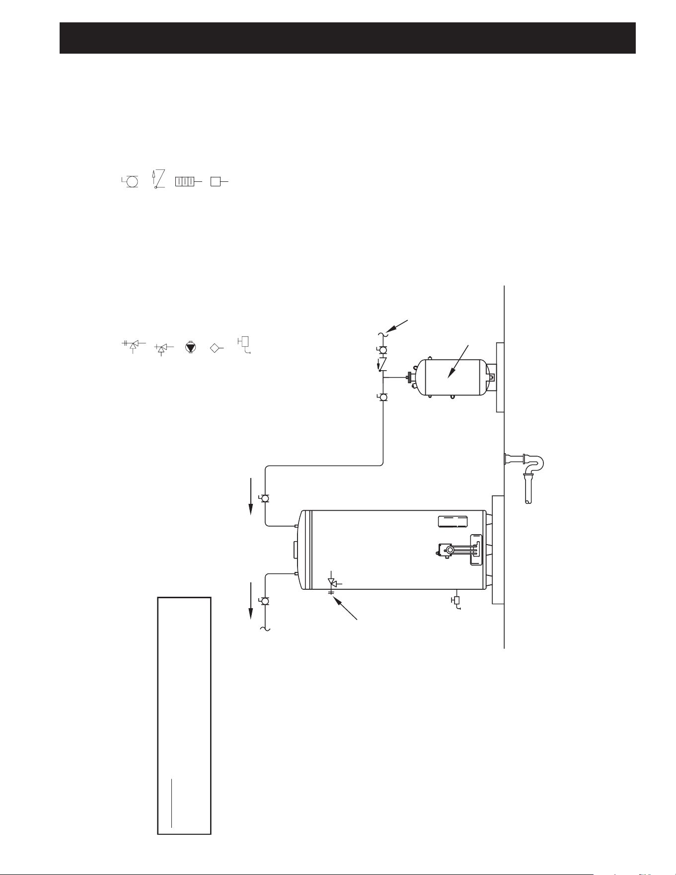
39
NOTES:
1.
Preferred piping diagram
.
2.
The temperature and pressure relief valve setting shall not exceed pressure rating of any component in the system
.
3.
Service valves are shown for servicing unit. Howeve
r, local codes shall govern their usage.
4. The Tank Te mperature Control should be wired to and control the pump between the water heater(s) and the storage tank(s).
SINGLE FL
UE - (1 UNIT)
LEGEND
TEMPERATURE & PRESSURE
RELIEF VALVE
PRESSURE RELIEF VALVE
CIRCULATING PUMP
TANK TEMPERATURE CONTROL
DRAIN
FULL PORT BALL VALV
E
TEMPERATURE GAGE
WATER FLOW SWITCH
CHECK VALVE
WARNING: THIS DRAWING SHOWS SUGGESTED
PIPING CONFIGUR
ATION AND OTHER DEVICES;
CHECK WITH LOCA
L CODES AND ORDINANCES
FOR ADDITIONAL
REQUIREMENTS.
FINISHED
FLOOR
HO CTOLD
COLD
EXPANSION
TANK
COLD WATER
SUPPLY
PIPE T&P TO
OPEN DRAIN
WATER PIPING DIAGRAMS
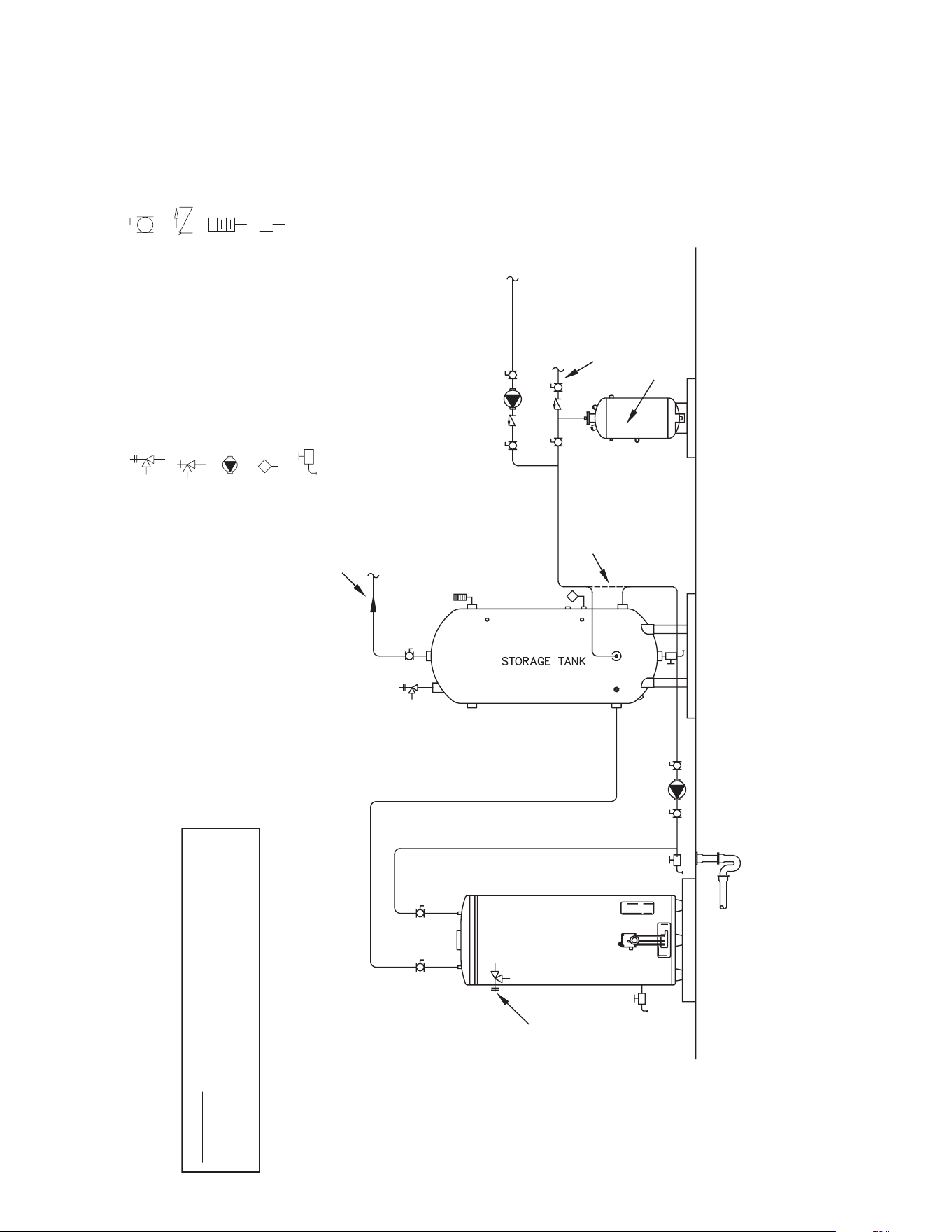
40
NOTES:
1. Preferred piping diagram.
2. The temperature and pressure relief valve setting shall not exceed pressure rating of any component in the system.
3. Service valves are shown for servicing unit. However, local codes shall govern their usage.
4. The Tank Temperature Control should be wired to and control the pump between the water heater(s) and the storage tank(s).
5. The water heater’s operating thermostat should be set 5 degrees F higher than the Tank Temperature Control.
SINGLE F
LUE
- (1 UNIT) WITH VE
RTICAL STORAGE TANK
LEGEND
TEMPERATURE & PRESSURE
RELIEF VALVE
PRESSURE RELIEF VALVE
CIRCULATING PUMP
TANK TEMPERATURE CONTROL
DRAIN
FULL PORT BALL VALVE
TEMPERATURE GAGE
WATER FLOW SWITCH
CHECK VALVE
W
ARNING:
THIS DRAWING SHOWS SUGGESTED
PIPING CONFIGUR
ATION AND OTHER DEVICES;
CHECK WITH LOCA
L CODES AND ORDINANCES
FOR
ADDITIONA
L REQUIREMENTS.
FINISHED
FLOOR
HOT COLD
EXPANSION
TANK
COLD WATER
SUPPLY
HOT WATER
RETURN FROM
FIXTURES
HOT WATER
TO FIXTURES
ALT. COLD
WATER CONNECTION
PIPE T&P TO
OPEN DRAIN
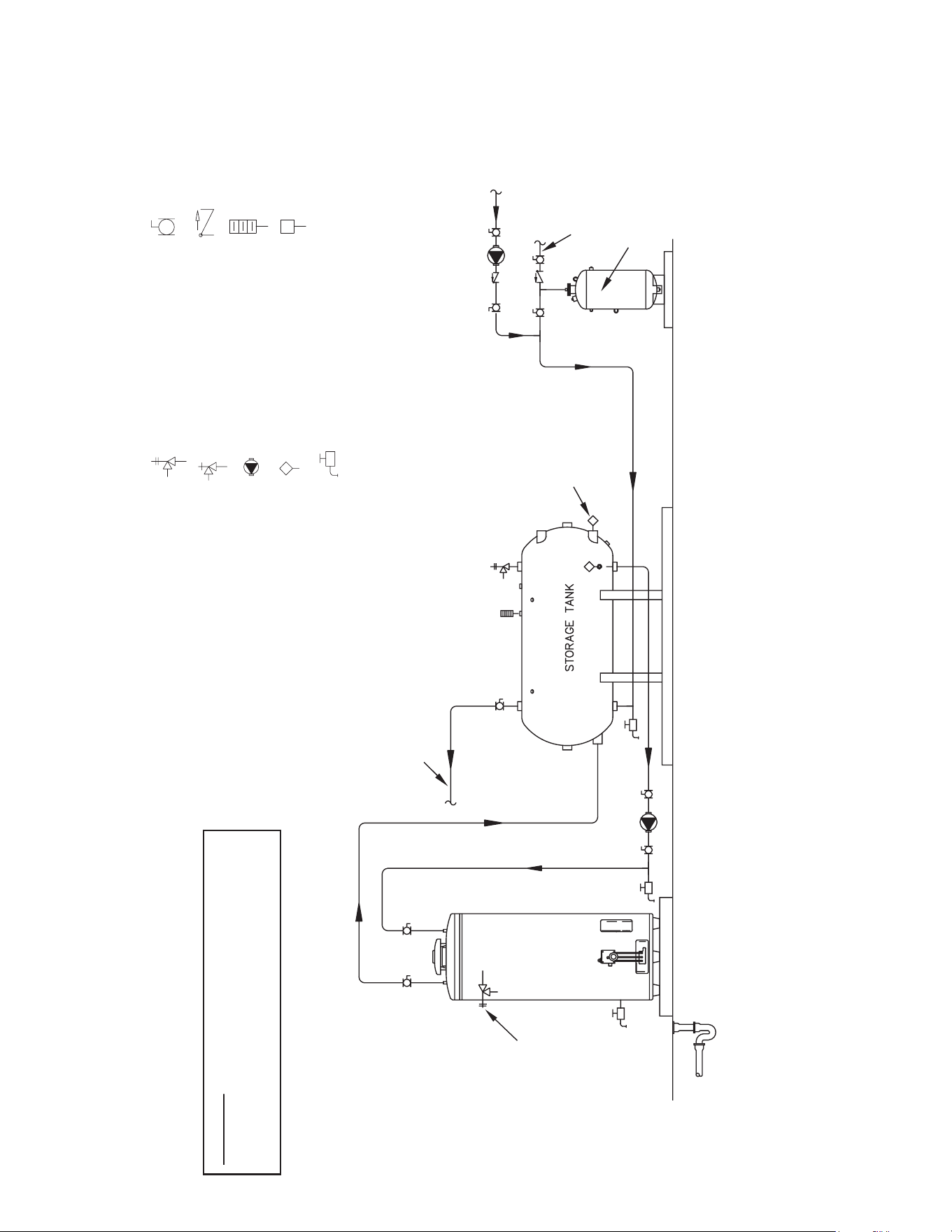
41
NOTES:
1. Preferred piping diagram.
2. The temperature and pressure relief valve setting shall not exceed pressure rating of any component in the system.
3. Service valves are shown for servicing unit. However, local codes shall govern their usage.
4. The Tank Temperature Control should be wired to and control the pump between the water heater(s) and the storage tank(s).
5. The water heater’s operating thermostat should be set 5 degrees F higher than the Tank Temperature Control.
SINGLE F
LUE
- (1 UNIT) WITH HORIZON
TAL STORAGE TANK
LEGEND
TEMPERATURE & PRESSURE
RELIEF VALVE
PRESSURE RELIEF VALVE
CIRCULATING PUMP
TANK TEMPERATURE CONTROL
DRAIN
FULL PORT BALL VALVE
TEMPERATURE GAGE
WATER FLOW SWITCH
CHECK VALVE
W
ARNING:
THIS DRAWING SHOWS SUGGESTED
PIPING CONFIGUR
ATION AND OTHER DEVICES;
CHECK WITH LOCA
L CODES AND ORDINANCES
FOR
ADDITIONA
L REQUIREMENTS.
FINISHED
FLOOR
HOT COLD
EXPANSION
TANK
COLD WATER
SUPPLY
HOT WATER
RETURN FROM
FIXTURES
HOT WATER
TO FIXTURES
ALTERNATE
LOCATION
PIPE T&P TO
OPEN DRAIN
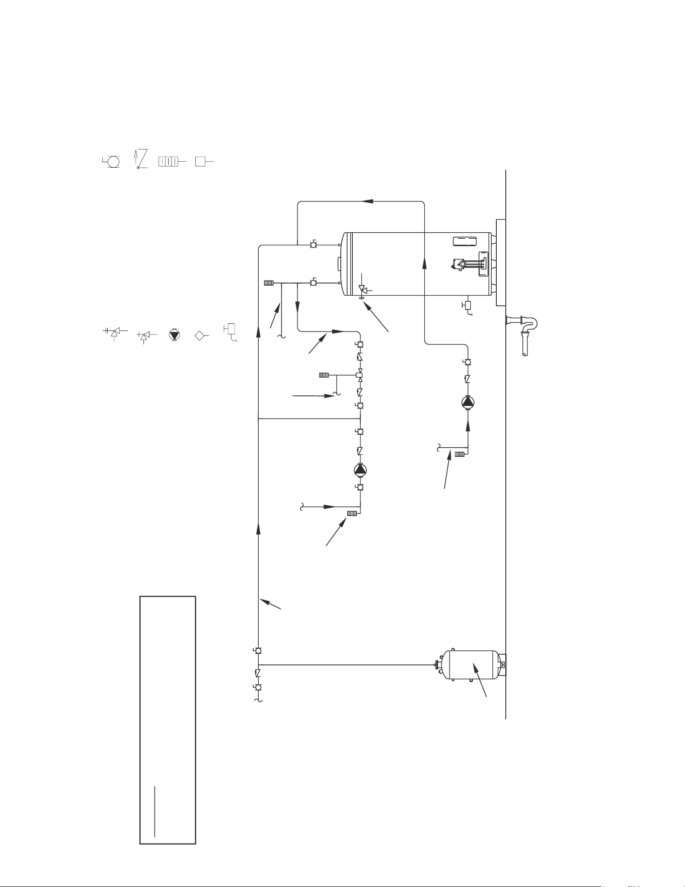
42
NOTES
:
1.
Preferred piping
diagram.
2.
The temperature and pressure relief valve setting shall not exceed pressure rating of any component in the system
.
3.
Service valves are shown for servicing unit. Howeve
r, local codes shall govern their usage.
4. The Tank T
emperature Control should be wired to and control the pump between the water heater(s) and the storage tank(s)
.
5. The water heater’s operating thermostat should be set 5 degrees F higher than the Tank Temperature Control.
SINGLE F
LUE
- (1 UNIT) WITH MIXING
VALVE TWO TEMPERATURE
LEGEND
TEMPERATURE & PRESSURE
RELIEF VALVE
PRESSURE RELIEF VALVE
CIRCULATING PUMP
TANK TEMPERATURE CONTROL
DRAIN
FULL PORT BALL VALVE
TEMPERATURE GAGE
WATER FLOW SWITCH
CHECK VALVE
W
ARNING:
THIS DRA
WING SHOWS SUGGESTED
PIPING CONFIGUR
ATION AND OTHER DEVICES;
CHECK WITH LOCA
L CODES AND ORDINANCES
FOR
ADDITIONA
L REQUIREMENTS.
HOT WATER
RETURN
MINIMUM
10´´ to 12´´
HOT WATER OUTLET
TEMPERED
WATER
RETURN
TEMPERED
WATER
OUTLET
COLD WATER
SUPPLY
LINE
TEMPERATURE
CONTROL
COLDHOT
EXPANSION
TANK
PIPE T&P TO
OPEN DRAIN
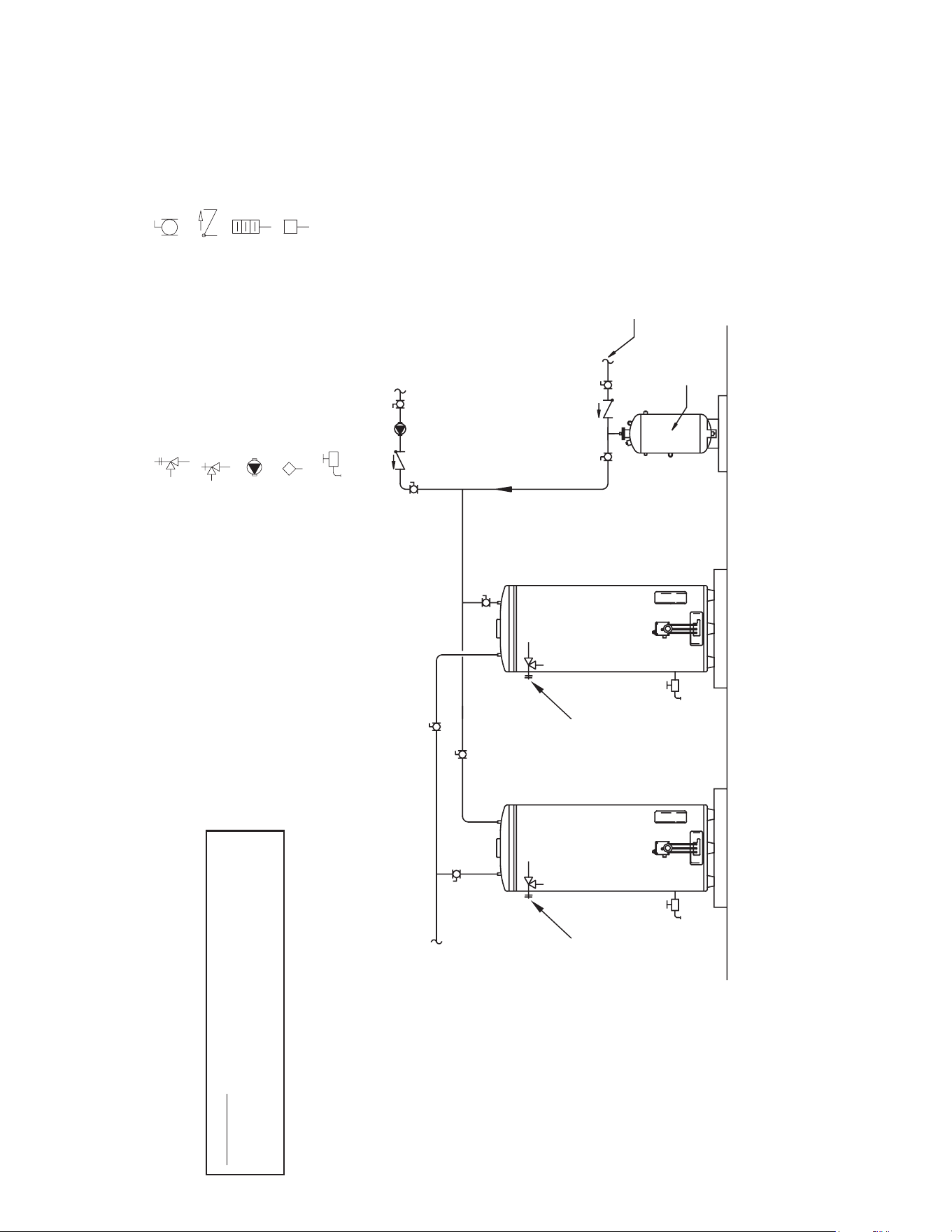
43
NOTES:
1. Preferred piping diagram.
2. The temperature and pressure relief valve setting shall not exceed pressure rating of any component in the system.
3. Service valves are shown for servicing unit. However, local codes shall govern their usage.
4. The Tank Temperature Control should be wired to and control the pump between the water heater(s) and the storage tank(s).
SINGLE F
LUE - (2 UNITS)
LEGEND
TEMPERATURE & PRESSURE
RELIEF VALVE
PRESSURE RELIEF VALVE
CIRCULATING PUMP
TANK TEMPERATURE CONTROL
DRAIN
FULL PORT BALL VALVE
TEMPERATURE GAGE
WATER FLOW SWITCH
CHECK VALVE
W
ARNING:
THIS DRAWING SHOWS SUGGESTED
PIPING CONFIGUR
ATION AND OTHER DEVICES;
CHECK WITH LOCA
L CODES AND ORDINANCES
FOR
ADDITIONA
L REQUIREMENTS.
FINISHED
FLOOR
HOT WATER
TO FIXTURES
HOT COL HD OT
HOT WATER RETURN
FROM FIXTURES
COLD
COLD WATER
SUPPLY
EXPANSION
TANK
PIPE T&P TO
OPEN DRAIN
PIPE T&P TO
OPEN DRAIN
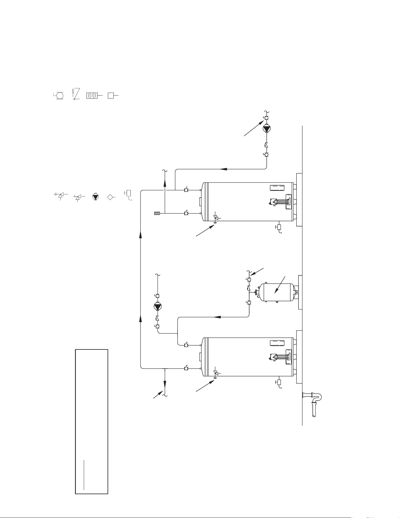
44
NOTES:
1. Preferred piping diagram.
2. The temperature and pressure relief valve setting shall not exceed pressure rating of any component in the system.
3. Service valves are shown for servicing unit. However, local codes shall govern their usage.
SINGLE F
LUE - (2 UNITS) TWO TEMPERATURE ONE PRE-HEATER/ONE BOOSTER HEATER
LEGEND
TEMPERATURE & PRESSURE
RELIEF VALVE
PRESSURE RELIEF VALVE
CIRCULATING PUMP
TANK TEMPERATURE CONTROL
DRAIN
FULL PORT BALL VALVE
TEMPERATURE GAGE
WATER FLOW SWITCH
CHECK VALVE
W
ARNING:
THIS DRAWING SHOWS SUGGESTED
PIPING CONFIGUR
ATION AND OTHER DEVICES;
CHECK WITH LOCA
L CODES AND ORDINANCES
FOR
ADDITIONA
L REQUIREMENTS.
FINISHED
FLOOR
HOT WATER
TO FIXTURES
HOT WATER RETURN
HOT HOTCOLD
HIGH
TEMPERATURE
RETURN
HIGH
TEMPERATURE
OUTLET
COLD WATER
SUPPLY
EXPANSION
TANK
PIPE T&P TO
OPEN DRAIN
PIPE T&P TO
OPEN DRAIN
BOOSTER
HEATER

45
NOTES

46
EFFECTIVE
For 3 Years, in the event of a tank leak, we will repair or, at
our discretion, replace the defective water heater.
For 1 Year, in the event of part failure, we will repair or, at
our discretion, replace the defective part.
We warrant this product against defects in materials or work-
manship as described in this document if installed within the
United States or Canada and provided the product remains
at its original place of installation.
Warranty coverage begins the date of installation OR the
date of manufacture if installation cannot be verified.
WHAT'S COVERED
Subject to these terms, in the event of defect in materials
and/or workmanship resulting in a tank leak during the first
three years, we will:
• Replace the water heater should the tank leak.
Subject to these terms, in the event of a defect in materials
and/or workmanship appearing during the first year, we will:
• Repair or, at our discretion, replace any part of the water heater
covered under this limited warranty excluding parts subject to
normal maintenance (Example: non-electronic anode rod, lter,
etc)
Service/labor, shipping, delivery, installation, handling
or any other costs are not covered at any time under this
warranty.
Any replacement part or product will be warranted only for
the unexpired portion of the original water heater’s limited
warranty period.
If an identical model is no longer available due to a change
in law, regulation, or standard, we will replace the product
with one having comparable capacity and input. In these
instances, the owner will have the option of paying the differ-
ence between what was paid for the original model and the
new model with the additional features, or receiving a refund
of the portion of the purchase price, on a pro-rata basis al-
locable to the unexpired portion of the warranty.
WHAT'S NOT COVERED
• Problems caused by improper: gas supply line sizing, gas type,
venting, connections, combustion air, voltage, wiring, or fusing
• Failure to follow applicable codes
• Failure to follow printed instructions
• Abuse, misuse, accident, re, ood, Acts of God
• Improper installation, sizing, delivery, or maintenance
• Claims related to rust, noise, smell, or taste of water
• Failure to conduct authorized factory start up if required
• Alterations to the water heater
• Non-outdoor heaters installed outdoors
• Damages due to a failure to allow for thermal expansion
• Heat exchanger failure due to lack of adequate / proper supply
of water
• Heaters moved from their original location
• Service trips to explain proper installation, use, or maintenance
of the product/unit or to describe compliance requirements
under applicable codes and regulations
• Charges related to accessing your heater including but not
limited to door/wall removal, equipment rental, etc.
• Replacement parts after expiration of this warranty
LIMITATIONS
NOTWITHSTANDING ANYTHING ELSE TO THE CON-
TRARY, THIS IS YOUR SOLE AND EXCLUSIVE WARRAN-
TY. ALL OTHER WARRANTIES INCLUDING A WARRANTY
OF MERCHANTABILITY OR FITNESS FOR PARTICULAR
PURPOSE ARE EXPRESSLY DISCLAIMED. SELLER SHALL
NOT BE LIABLE FOR ANY CONSEQUENTIAL, INCIDENTAL,
SPECIAL, PUNITIVE OR OTHER INDIRECT DAMAGES.
TOTAL LIABILITY ARISING AT ANY TIME SHALL NOT
EXCEED THE PURCHASE PRICE PAID WHETHER BASED
ON CONTRACT, TORT, STRICT LIABILITY OR ANY OTHER
LEGAL THEORY.
SERVICE INQUIRIES:
For service inquiries call the telephone number listed below. Be prepared to provide the following information: name, ad-
dress and telephone number; the model and serial number of the water heater; proof of installation; and a clear description
of the problem.
For your records, fill in the product:
Serial: ___________________
Model: ___________________
U. S. Customers:
A. O. Smith Corporation
500 Tennessee Waltz Parkway
Ashland City, Tennessee 37015
800 527-1953
www.hotwater.com
Canadian Customers:
P. O. Box 310
768 Erie Street
Stratford (Ontario) N5A6T3
800 527-1953
COMMERCIAL WATER HEATER LIMITED WARRANTY

47
