REV250618
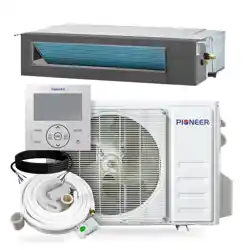
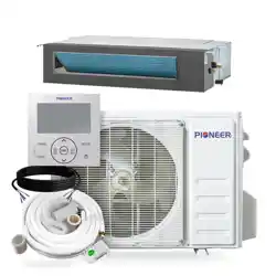
DUCTLESS MINI SPLIT SYSTEM AIR CONDITIONER / HEAT PUMP
RYB-20 Inverter Series
For 36,000-48,000 BTU/hr Systems
Quantum Ultra (R-454B) - RB Indoor and YN Outdoor
Installation &
User Manual
IMPORTANT NOTICE:
Read this manual carefully before installing or
operating your new air conditioning system. Be
sure to save this manual for future reference.
Table of Contents
20
1 Safety Precautions............................ 2
18
23
2 Product Overview.............................
3
Product Installation...........................
4
Indoor Unit Installation......................
43
5 Outdoor Unit Installation................... 35
39
48
6 Refrigerant Piping Connection........
7
Wiring Precautions..........................
8
Air Evacuation.................................
Air Conditioner Installation & User Manual
10
Test Run..........................................
51
9
Note on Adding Refrigerant.............
50
12
Unpacking & Packing......................
55
11 Commission..................................... 53
13
Care & Maintenance.......................
56
Read this Manual
The manual provides helpful hints on using and maintaining the air conditioner properly. Performing preventive care can save time and
money over the lifespan of the air conditioner. These instructions may not cover every possible condition of use, so common sense and
attention to safety is required when installing, operating, and maintaining this product.
T
Troubleshooting...............................
57
1
Air Conditioner Installation & User Manual
Safety Precautions
1
It is important to read this section before operating and installing the system. Incorrect installation due to
ignoring instructions can cause serious damage or injury. The seriousness of potential damage and injuries is
classified as either a warning or caution.
Explanation of Symbols
WARNING
This symbol indicates the possibility of personal injury or loss of life.
CAUTION
This symbol indicates the possibility of property damage or serious consequences.
WARNING
Children aged 8 and above, as well as individuals with lack of experience or reduced physical, sensory, or
mental capabilities can use the appliance if supervision or instruction is given. Do not allow children to play with
or near the appliance. Children or untrained personnel should be restricted from cleaning and performing
maintenance on the appliance, unless they're given supervision.
WARNINGS FOR PRODUCT USE
• Turn off the air conditioner and disconnect the power before cleaning, installing, or repairing the system.
Failure to do so can cause electric shock.
• If an abnormal situation arises (such as a burning smell), immediately turn off the unit and disconnect the
power. Call the dealer for instructions to avoid electrical shock, fire, or injury.
• Do not insert fingers, rods, or other objects into the air inlet or outlet. This could cause injury because the fan
rotates at high speeds.
• Do not use flammable sprays such as hair spray, lacquer, or paint near the unit. This may cause fire or
combustion.
• Do not operate the air conditioner in locations near or around combustible gases. Emitted gas may collect
around the unit and cause an explosion.
• Do not operate the air conditioner in a wet room such as a bathroom or laundry room. Too much exposure to
water can cause electrical components to short circuit.
• Do not expose your body directly to cool air for prolonged durations of time.
• If the air conditioner is used together with burners or other heating devices, thoroughly ventilate the room to
avoid oxygen deficiency.
• In certain functional environments (such as kitchens, server rooms, etc.), it is highly recommended to use
specifically designed air-conditioning units.
2

Air Conditioner Installation & User Manual
Safety Precautions
1
WARNINGS FOR PRODUCT INSTALLATION
• Turn off the air conditioner and disconnect its power supply before installing or repairing the system. Failure to
do so can cause electric shock.
• An authorized dealer or specialist must perform the installation. Incorrect installation can cause water leakage,
electrical shock, or fire.
• Perform the installation according to the instructions in this manual. Improper installation can cause water
leakage, electrical shock, or fire.
• Contact an authorized service technician to maintain and repair the unit.
• Install the appliance in accordance with national wiring regulations. Only use the included accessories, parts,
and specified parts for installation. Using non-standard parts can cause water leakage, electrical shock, fire, or
unit failure.
• Install the unit in a firm location that can support the unit's weight. If the chosen location cannot support the
unit's weight or the installation is done incorrectly, the unit may drop and cause serious injury or damage.
• For units with an auxiliary electric heater, do not install the unit within 3 feet (1 m) of any combustible materials.
• For units that have a wireless network function (USB device access replacement), professional staff must carry
out the maintenance operations.
• Do not install the unit in a location that may be exposed to combustible gas leaks. If combustible gas
accumulates around the unit, it could cause fire.
• Do not turn on the power until all work has been completed.
• When moving or relocating the air conditioner, consult experienced service technicians for the disconnection
and reinstallation of the unit.
• For information on installing the appliance to its support, read the Indoor Unit Installation and Outdoor Unit
Installation sections.
ELECTRICAL WARNINGS
• Only use the specified wire. If the wire is damaged, it must be replaced by the manufacturer, service agent, or
a similarly qualified individual in order to avoid a hazard.
• Properly ground the product during installation to avoid electrical shock.
• Incorporate disconnection in the fixed wiring, according to the wiring rules.
• Do not share the electrical outlet with other appliances. Improper or insufficient power supply can cause fire or
electric shock.
3
Air Conditioner Installation & User Manual
Safety Precautions
1
• For all electrical work, follow the local and national wiring standards, regulations, and installation manual.
Connect the cables tightly, then clamp them securely to prevent external forces from damaging the terminal.
Improper electrical connections can result in electrical shock or fire. Complete the electrical connections
according to the Electrical Connection diagram located on the panels of the indoor and outdoor units.
• Properly arrange all wiring to ensure that the control board cover can close correctly. If the control board cover
is not closed properly, it can lead to corrosion and cause the connection points on the terminal to heat up and
catch fire. It can also cause electrical shock.
• If connecting power to fixed wiring, incorporate an all-pole disconnection device in the fixed wiring. Ensure that
the device is in accordance with the wiring rules.
• Turn off the air conditioner and disconnect the power if the unit will not be used for a long duration of time.
• Turn off and unplug the unit during storms.
• Make sure that water condensation can drain unhindered from the unit.
• Do not operate the air conditioner with wet hands. This may cause electrical shock.
• Do not use the device for any other purpose than its intended use.
• Do not climb onto or place objects on top of the outdoor unit.
• Do not allow the air conditioner to operate for long periods of time with doors or windows open, or if the
humidity is considerably high.
TAKE NOTE OF FUSE SPECIFICATIONS
The air conditioner's circuit board (PCB) is designed with a fuse to provide overcurrent protection. The
specifications of the fuse are printed on the circuit board. For example: T3.15AL/250VAC, T5AL/250VAC,
T3.15A/250VAC, T5A/250VAC, T20A/250VAC, T30A/250VAC, etc.
Note: Only use the blast-proof ceramic fuse.
CAUTION
4
CLEANING & MAINTENANCE WARNINGS
• Turn off the device and disconnect its
power supply
before cleaning. Failure to do so can cause an electrical
shock.
• Do not clean the air conditioner with excessive amounts of water.
• Do not clean the air conditioner with combustible cleaning agents. Combustible cleaning agents can cause
fire or deformation.
Air Conditioner Installation & User Manual
Safety Precautions
1
WARNING FOR USING FLAMMABLE REFRIGERANTS
• Do not use means to accelerate the defrosting and cleaning processes, other than those recommended by
the manufacturer.
• Store the appliance in a room without continuously operating ignition sources. For example: open flames, an
operating gas appliance, or an operating electric heater.
• Do not pierce or burn.
• Be aware that refrigerants may not contain an odor.
R-454B refrigerant charge amount and minimum room area:
The machine you purchased may be one of the types listed in the table below. The indoor and outdoor units are
designed to be used together. Check the machine that was purchased. Install the indoor unit at least 7.6 feet (2.3
m) above the floor. The height of the room cannot be less than the indoor unit's installed height. The minimum
room area of operation or storage is as specified in the following table:
For the units with refrigerant sensors, when the unit detects a refrigerant leak, the minimum airflow of the indoor
unit is as follows:
Indoor Unit
Outdoor Unit
Model
36K RB036GMSILDFHG
48K RB048GMSILDFHG
YN036GMSI20RUG
YN048GMSI20RUG
Room Size Restriction
The appliances are connected via an air duct system to one or more rooms. The bottom of the air duct's air outlet
must be at a height of ≥ 7.3 feet (2.2 m) from the floor. In UL/CSA 60335-2-40, the R-454B refrigerant is
classified as mildly flammable refrigerants, which will limit the room area of the system service. Similarly, the total
amount of refrigerant should be less than or equal to the maximum allowable refrigerant charge, which depends
on the room area serviced by the system.
Note: The following are explanations for the nouns in this section:
• Mc: The actual refrigerant charge in the system.
• A: The actual room area where the appliance is installed.
• Amin: The required minimum room area.
• Mmax: The allowable maximum refrigerant charge in a room.
• Qmin: The minimum circulation airflow.
• Anvmin: The minimum opening area for connected rooms.
• TAmin: The total area of the conditioned space (For appliances serving one or more rooms with an air duct
system).
• TA: The total area of the conditioned spaced connected by air ducts.
5
Air Conditioner Installation & User Manual
Safety Precautions
1
Refrigerant Charge & Room Area Limitations
For the purpose of determining the room area (A) when calculating the maximum allowable refrigerant charge
(Mmax) in an unventilated space, the following shall apply:
The room area (A) should be defined as the room area enclosed by the projection to the floor of the walls,
partitions, and doors of the space in which the appliance is installed. Spaces connected by only drop ceilings,
ductwork, or similar connections should not be considered a single space.
For units mounted higher than 5.9 feet (1.8 m), the spaces divided by partition walls that are no higher than 5.2
feet (1.6 m) should be considered a single space.
For fixed appliances, the rooms on the same floor and connected by an open passageway between the spaces
can be considered a single room when determining compliance to Amin, if the passageway complies with all of
the following:
• It is a permanent opening.
• It extends to the floor.
• It is intended for people to walk through.
For fixed appliances, the area of the adjacent rooms on the same floor that are connected by permanent
openings in the walls and/or doors between occupied spaces, including gaps between the wall and floor, can be
considered a single room when determining compliance to Amin. The following must be met:
The space must have appropriate openings according to Sec. 2.
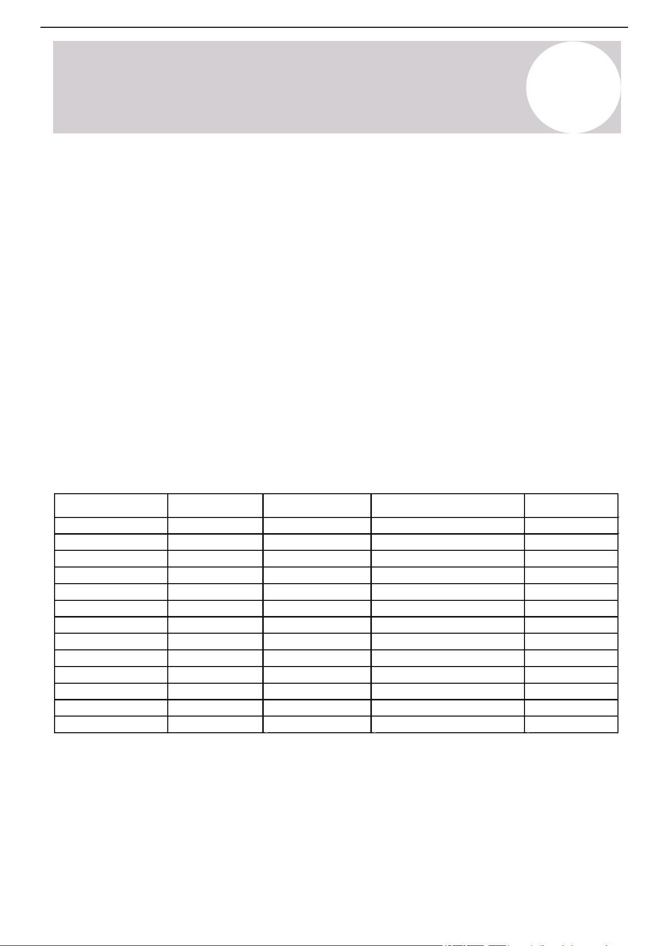
The minimum opening area for natural ventilation Anvmin must not be less than the following:
Height of outlet/m Mc/Kg
Mmax/kg
2.2
2.2
2.2
2.2
2.2
2.2
2.2
2.2
2.2
2.2
2.2
2.2
2.2
5 6.0 1.628 0.108
6 6.0 1.954 0.100
7 6.0 2.279 0.092
8 6.0 2.605 0.084
9 6.0 2.930 0.076
10 6.0 3.256 0.068
11 6.0 3.582 0.060
12 6.0 3.907 0.052
13 6.0 4.233 0.044
14 6.0 4.493 0.038
15 6.0 4.651 0.034
16 6.0 4.803 0.031
17 6.0 4.951 0.027
Note: Take the Mc=6.0kg as an example. For appliances serving one or more rooms with an air duct system, the
room area calculation should be determined based on the total area of the conditioned space connected by
ducts. Take into consideration that the circulating airflow distributed to all the rooms by the appliance's integral
indoor fan will mix and dilute the leaking refrigerant before entering any room.
A/m
2
Anvmin/m
2
6

Air Conditioner Installation & User Manual
Safety Precautions
1
Opening Conditions for Connected Rooms
When the openings for connected rooms are required, apply the following conditions:
• The area of any openings above 11.8 inches (300 mm) from the floor should not be considered in determining
the compliance with Anvmin.
• At least 50% of the required opening area Anvmin should be below 7.8 inches (200 mm) from the floor.
• The bottom of the lowest opening must not be higher than the point of release when the unit is installed and
not more than 3.9 inches (100 mm) from the floor.
• Openings are permanent openings which cannot be closed.
• For openings extending to the floor, the height should not be less than 0.7 inches (20 mm) above the surface
of the floor covering.
• A second higher opening should be provided. The total size of the second opening should not be less than
50% of the minimum opening area for Anvmin and be at least 4.9 feet (1.5 m) above the floor.
Note: The requirement for the second opening can be met by drop ceilings, ventilation ducts, or similar
arrangements that provide an airflow path between the connected rooms.
• The room into which refrigerant can leak,
plus the connected adjacent room (s)
should have a total area of not less than
TAmin.
• The room area in which the unit is installed
should not be less than 20% TAmin.
7
Air Conditioner Installation & User Manual
Safety Precautions
1
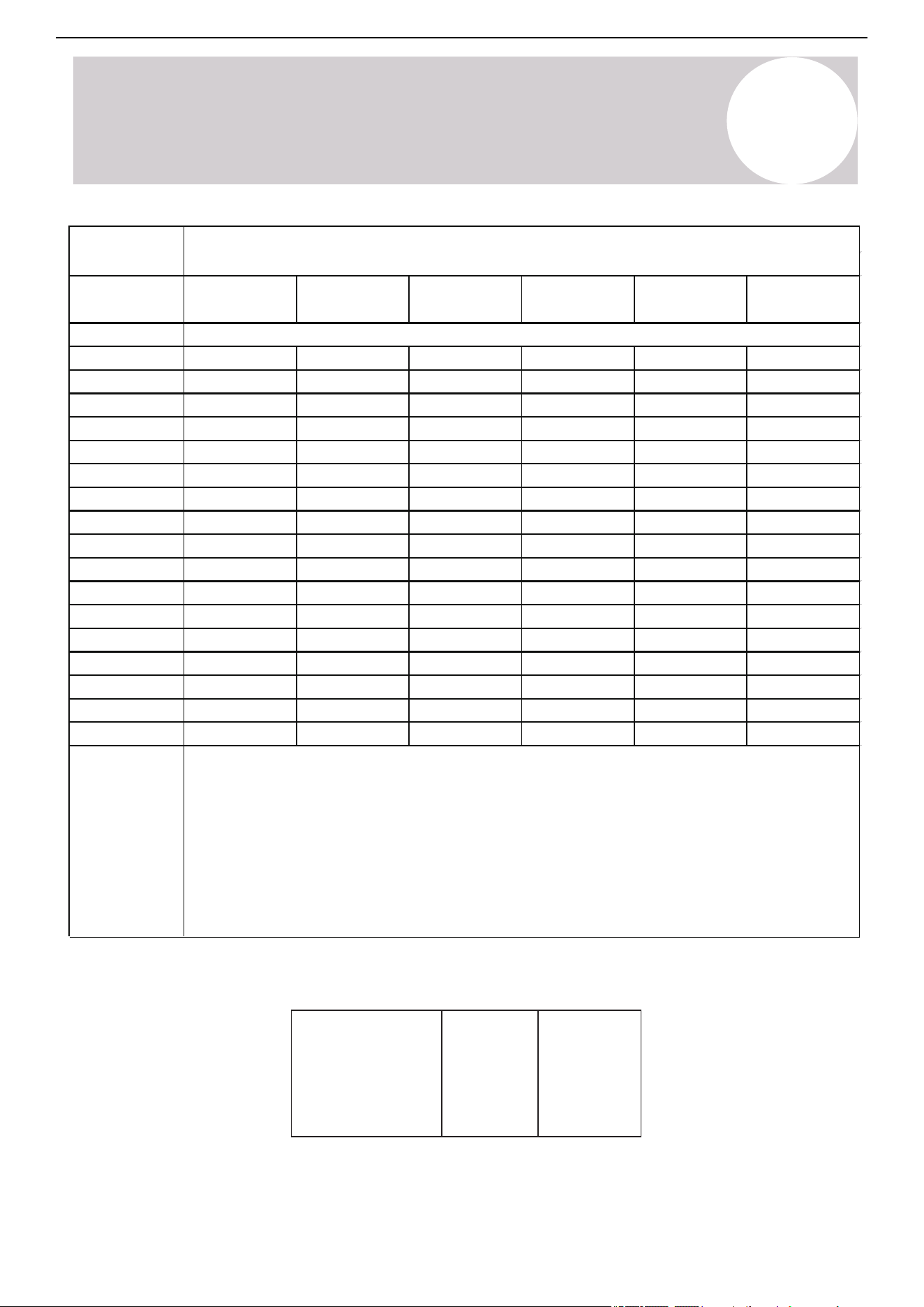
m
c
or m
REL
[ozs/kg]
7.6/2.3 7.9/2.4 8.6/2.6 9.2/2.8
<=62.6/1.776
Area
formula
h
inst
[ft/m]
12/1.10
63.4/1.8
70.5/2.0
77.5/2.2
84.6/2.4
91.7/2.6
98.7/2.8
105.8/3.0
112.8/3.2
119.9/3.4
126.9/3.6
134/3.8
141.0/4.0
148.1/4.2
155.1/4.4
162.2/4.6
169.2/4.8
176.3/5.0
47/4.35
52/4.83
58/5.31
63/5.80
68/6.28
73/6.76
78/7.24
84/7.73
89/8.21
94/8.69
99/9.17
104/9.66
110/10.14
115/10.62
120/11.11
125/11.59
130/12.07
51/4.68
56/5.20
62/5.72
68/6.24
73/6.76
79/7.28
84/7.80
90/8.32
96/8.84
101/9.36
107/9.88
118/10.92
124/11.44
129/11.96
135/12.48
140/13.00
55/5.07
61/5.64
67/6.20
73/6.76
79/7.32
85/7.89
91/8.45
97/9.01
104/9.58
110/10.14
122/11.27
128/11.83
134/12.39
140/12.96
146/13.52
152/14.08
6.0~7.3/
1.8~2.2
60/5.53
67/6.15
73/6.76
80/7.38
86/7.99
93/8.60
100/9.22
106/9.83
113/10.45
120/11.06
126/11.68
133/12.29
139/12.90
146/13.52
153/14.13
159/14.75
166/15.36
57/5.29
64/5.88
70/6.47
83/7.64
89/8.23
95/8.82
102/9.41
108/9.99
114/10.58
121/11.17
127/11.76
133/12.34
140/12.93
146/13.52
152/14.11
159/14.69
76/7.06
9.9/3.0
44/4.06
49/4.51
54/4.96
59/5.41
64/5.86
68/6.31
73/6.76
78/7.21
83/7.66
88/8.11
93/8.56
97/9.01
102/9.46
107/9.91
112/10.37
117/10.82
122/11.27
112/10.40
116/10.70
A
min
[ft
2
/ m
2
]
• A
min
is the required minimum room area in ft
2
/m
2
.
• M
c
is the actual refrigerant charge in the system in oz/kg
• M
REL
is the refrigerant releasable charge in oz/kg (applicable to the units with refrigerant
sensors only)
• h
inst
is the height of the bottom of the appliance relative to the floor of the room after
installation.
WARNING: The minimum room area or minimum room of conditioner space is based on the
releasable charge and total system refrigerant charge.
Model
Nominal air
volume
36K 48K
1176CFM
2000m
3
/h
1588CFM
2700m
3
/h
When the unit detects a refrigerant leak, the minimum airflow of the indoor unit is the following:
8

Air Conditioner Installation & User Manual
Safety Precautions
1
9
1. Installation
(Where refrigerant pipes are allowed)
- Any individual who is involved with working on or breaking into a refrigerant circuit must hold a valid certificate
from an industry-accredited assessment authority. The certificate authorizes the individual's competence for
handling refrigerants safely in accordance with the specifications of an industry recognized assessment.
- Maintenance and repairs requiring the assistance of other skilled personnel must be carried out under the
supervision of the individual competent in the use of flammable refrigerants.
- Keep the installation of the pipe-work to a minimum.
- Protect the pipe-work from physical damage.
- Ensure that the refrigerant pipes comply with national gas regulations.
- Ensure that the mechanical connections are accessible for maintenance purposes.
- Do not allow foreign matter (oil, water, etc.) from entering the piping. In addition, when storing the piping,
securely seal the opening by pinching, taping, etc.
- Competent individuals must carry out all working procedures that affect safety.
- Store the appliance in a well-ventilated area where the room size corresponds to the room area as specified for
operation.
- Test the joints using detection equipment with a capability of 5g/year of refrigerant or better. After installation,
ensure that the equipment is at a standstill and maintained under operating pressure, or at least the minimum
standstill pressure.
- In cases that require mechanical ventilation, ensure that the ventilation openings are kept clear of obstruction.
- Leak Detection System Installed: Power the unit except for service.
For units with refrigerant sensors, when the sensor detects refrigerant leakage, the indoor unit will display an
error code and emit a buzzing sound, the outdoor unit's compressor will immediately stop, and the indoor fan will
start running. The service life of the refrigerant sensor is 15 years. When the refrigerant sensor malfunctions, the
indoor unit will display the "FHCC" error code. The refrigerant sensor cannot be repaired and can only be
replaced by the manufacturer. Replace the sensor with one specified by the manufacturer.
(Applicable to units with refrigerant sensors only.)
2. When a flammable refrigerant is used, the requirements for the installation space of the appliance and/or
ventilation are determined according to the:
- Mass charge amount (M) used in the appliance.
- Installation location.
- Ventilation type of the location or appliance.
- Protect the piping material and pipe routing from physical damage during operation and service. Ensure that
the piping material and pipe routing are in compliance with national and local codes and standards, such as
ASHRAE 15, IAPMO Uniform Mechanical Code, ICC International Mechanical Code, or CSA B52. All field joints
must be accessible for inspection prior to being covered or enclosed.
- Protect piping, fittings, and protection devices from adverse environmental effects. For example, water
collecting and freezing in relief pipes or the accumulation of dirt and debris.

Air Conditioner Installation & User Manual
Safety Precautions
1
- Ensure that the piping in the refrigerant system is designed and installed to minimize the likelihood of hydraulic
shock damaging the system.
- Before applying any insulation, protect the steel pipes and components against corrosion with a rustproof
coating.
- Take precautions to avoid excessive vibration or pulsation.
- The minimum floor area of the room is mentioned in the form of a table or single figure without reference to a
formula.
- After completing the field piping for split systems, pressure test the field pipework with an inert gas. Then,
vacuum test the pipework before refrigerant charging. Ensure that the testing is completed according to the
following requirements:
a. The minimum test pressure for the low side of the system must be the low side design pressure and the
minimum test pressure for the high side of the system must be the high side design pressure, unless the high
side of the system cannot be isolated from the low side of the system. If the high side cannot be isolated from the
low side of the system, the entire system must be pressure tested to the low side design pressure.
b. After removing the pressure source, maintain the test pressure for at least 1 hour, ensuring that there is no
decrease of pressure, which is indicated by the test gauge. Ensure that the test gauge resolution does not
exceed 5% of the test pressure.
c. During the evacuation test, after achieving a vacuum level specified in the manual, isolate the refrigeration
system from the vacuum pump and ensure that the pressure does not rise above 1,500 microns within 10
minutes. The appropriate vacuum pressure level is specified in the manual, and must not be less than 500
microns or the value required for compliance with national and local codes and standards. The codes and
standards may vary between residential, commercial, and industrial buildings.
- Field-made refrigerant indoor joints must be tightness tested according to the following requirements: The test
method must have a sensitivity of 5 grams per year of refrigerant or better under a pressure of at least 0.25 times
the maximum allowable pressure. No leak should be detected.
3. Qualification of Workers
The working personnel must be qualified to perform any maintenance, service, and repair operations. Competent
individuals must carry out working procedures that affect safety means. The competent individual must complete
the training by national training organizations or manufacturers that are accredited to teach the relevant national
competency standards set in legislation. The individual's competence must be documented by a certificate. All
training must follow the ANNEX HH requirements of UL 60335-2-40 4th Edition.
Examples for such working procedures are:
- breaking into the refrigerating circuit.
- opening of sealed components.
- opening of ventilated enclosures.
4. Well-Ventilated Area
Before breaking into the system or conducting any hot work, ensure that the area is in the open or is adequately
ventilated. Maintain a degree of ventilation while the work is being carried out. Ensure that the ventilation safely
disperses any released refrigerant and preferably expels it externally into the atmosphere.
5. Cabling
Confirm that the cabling will not be subject to wear, corrosion, excessive pressure, vibration, sharp edges, or any
other adverse environmental effects. The check should also take into account the effects of aging or continual
vibration from sources such as compressors or fans.
10

Air Conditioner Installation & User Manual
Safety Precautions
1
6. Detection of Flammable Refrigerants
Do not use potential sources of ignition for searching or detecting refrigerant leaks. Do not use a halide torch or
detector using a naked flame. Ensure that the detector is not a potential source of ignition and is suitable for the
refrigerant used. Leak detection equipment must be set at a percentage of the refrigerant LFL, and calibrated to
the refrigerant employed. Confirm the appropriate percentage of gas (25% maximum.
The following leak detection methods are deemed acceptable for refrigerant systems:
Electronic leak detectors: This type of detector can detect refrigerant leaks. However, in the case of flammable
refrigerants, the sensitivity may not be adequate and need recalibration. Calibrate the detection equipment in a
refrigerant-free area.
Leak detection fluids: The bubble method and fluorescent method agents are examples of leak detection
fluids. These are suitable to use with most refrigerants. Avoid using detergents containing chlorine as the
chlorine may react with the refrigerant and corrode the copper pipe-work.
If a leak is suspected, remove or extinguish all naked flames.
If a refrigerant leak is found and requires brazing, recover all the refrigerant from the system or use the shut off
valves to isolate the refrigerant in a part of the system remote from the leak. See the following instructions for
removing refrigerant.
7. Removal and Evacuation
Use conventional procedures when breaking into the refrigerant circuit to make repairs or for any other purpose.
However, for flammable refrigerants, it is important to follow this best practice since flammability is a
consideration.
Follow this procedure:
- Safely remove refrigerant following local and national regulations.
- Evacuate.
- Purge the circuit with inert gas (optional for A2L).
- Evacuate (optional for A2L).
- Continuously flush or purge with inert gas when using a flame to open the circuit.
- Open the circuit.
Recover the refrigerant charge into the correct recovery cylinders if venting is not allowed by local and national
codes. For appliances containing flammable refrigerants, purge the system with oxygen-free nitrogen to render
the appliance safe from flammable refrigerants. If needed, repeat this process several times. Do not use
compressed air or oxygen to purge refrigerant systems.
For appliances containing flammable refrigerants, purge the refrigerant by breaking the vacuum in the system
with oxygen-free nitrogen and continuing to fill until the working pressure is achieved. Then, vent to atmosphere
and finally pull down to a vacuum (optional for A2L). Repeat this process until no refrigerant is present within
the system (optional for A2L). When using oxygen-free nitrogen, vent the system down to atmospheric pressure
to enable work to take place. Ensure that the outlet for the vacuum pump is not close to any potential ignition
sources and ventilation is available.
11

Air Conditioner Installation & User Manual
Safety Precautions
1
8. Charging Procedures
In addition to conventional charging procedures, follow these requirements:
- Use only appropriate tools when completing work. In case of uncertainty, consult the manufacturer of the tools
for information on use with flammable refrigerants.
- Ensure that the contamination of different refrigerants does not occur when using charging equipment. Hoses
or lines must be as short as possible to minimize the amount of refrigerant contained in them.
- Keep the cylinders upright.
- Ensure that the refrigerant system is earthed before charging the system with refrigerant.
- Label the system when charging is complete (if not already).
- Take extreme care to not overfill the refrigeration system.
- Prior to recharging the system, it must be pressure tested with oxygen-free nitrogen. Leak test the system after
completing the charging but prior to commissioning. Carry out a follow up leak test before leaving the site.
9. Recovery
When removing refrigerant from a system, either for servicing or decommissioning, it is recommended good
practice to remove refrigerants safely. When transferring refrigerant into cylinders, ensure that only appropriate
refrigerant recovery cylinders are employed. Ensure that the correct number of cylinders for holding the total
system charge are available. Designate all the cylinders intended to be used.
Servicing Information
1. Inspect the Area
Before working on systems containing flammable refrigerants, safety checks are required to ensure that the risk
of ignition is minimized. The following precautions must be complied with prior to conducting repairs on the
system.
2. Work Procedure
To minimize the risk of flammable gas or vapor presence, conduct work using controlled procedures.
3. General Work Area
Inform all maintenance staff and individuals working in the local area about the nature of the work being
performed. Avoid working in confined spaces. Section off the area around the workspace. Ensure that the area
is safe by controlling flammable materials.
4. Check for Refrigerant
Check the area with an appropriate refrigerant detector before and during work to ensure that the technician is
aware of potentially flammable atmospheres. Ensure that the leak detection equipment is suitable for flammable
refrigerants, i.e. non-sparking, adequately sealed, or intrinsically safe.
5. Fire Extinguisher
If conducting hot work on the refrigeration equipment or any associated parts is needed, appropriate fire
extinguishing equipment must be available. Keep a dry powder or CO2 fire extinguisher adjacent to the charging
area.
12

Air Conditioner Installation & User Manual
Safety Precautions
1
13
6. No Ignition Sources
Individuals carrying out work involving exposed pipework on a refrigerant system are prohibited from using any
sources of ignition that may lead to a risk of fire or explosion. All possible ignition sources, such as cigarette
smoking, must be performed at a sufficient distance from the installation or maintenance site. Before conducting
work on the equipment, the surrounding area must be surveyed to ensure that there are no flammable hazards
or ignition risks. No Smoking signs must be displayed.
7. Well-Ventilated Area
Ensure that the area is open and well-ventilated before accessing the system or performing any work that
generates heat. Ventilation must be maintained to a certain degree while work is being carried out. The
ventilation should safely disperse any released refrigerant and expel it externally into the atmosphere.
8. Inspect the Refrigeration Equipment
When changing electrical components, they must be fit-for-purpose and meet the correct specifications. Follow
the manufacturer's maintenance and service guidelines at all times. If in doubt, consult the manufacturer's
technical department for assistance.
For installations using flammable refrigerants, check the following:
- Ensure that the charge size is appropriate for the room in which the refrigerant-containing parts are installed.
- Confirm the ventilation machinery and outlets are operating adequately and not obstructed.
- If an indirect refrigerating circuit is being used, check the secondary circuit for the presence of refrigerant.
- Confirm the equipment markings are visible and legible. Correct markings and signs that are illegible.
- Install the refrigeration pipe or components in a position that minimizes the risk of corrosion from harmful
substances, unless constructed of corrosion-resistant materials and suitably protected.
9. Inspect the Electrical Devices
Repairing and maintaining electrical components must include initial safety checks and component inspections.
If a fault exists that could compromise safety, do not connect the electrical supply to the circuit until the fault is
resolved. If the fault cannot be immediately corrected but it is necessary to continue operation, a temporary
solution must be implemented. If a temporary solution is implemented, it must be reported to the owner of the
equipment, ensuring both parties are informed.
Initial safety checks must include the following:
- Confirm the capacitors are discharged. Ensure that this is done in a safe manner to avoid the possibility of
sparking.
- Ensure that no live electrical components and wiring are exposed while charging, recovering, or purging the
system.
- Confirm there is continuity of earth bonding.
10. Replace Sealed Electrical Components If It's Damaged.
11. Replace Intrinsically Safe Components If It's Damaged.
12. Cabling
Confirm that the cabling will not be subject to wear, corrosion, excessive pressure, vibration, sharp edges, or
any other adverse environmental effects. The check should also take into account the effects of aging or
continual vibration from sources such as compressors or fans.

Air Conditioner Installation & User Manual
Safety Precautions
1
13. Detection of Flammable Refrigerants
Do not use potential sources of ignition for searching or detecting refrigerant leaks. Do not use a halide torch or
detector using a naked flame. Ensure that the detector is not a potential source of ignition and is suitable for the
refrigerant used. Leak detection equipment must be set at a percentage of the refrigerant LFL, and calibrated to
the refrigerant employed. Confirm the appropriate percentage of gas (25% maximum).
The following leak detection methods are deemed acceptable for refrigerant systems:
Electronic leak detectors: This detector can detect refrigerant leaks. However, in the case of flammable
refrigerants, the sensitivity may not be adequate and need recalibration. Calibrate the detection equipment in a
refrigerant-free area.
Leak detection fluids: The bubble method and fluorescent method agents are examples of leak detection fluids.
These are suitable to use with most refrigerants. Avoid using detergents containing chlorine as the chlorine may
react with the refrigerant and corrode the copper pipe-work.
If a leak is suspected, remove or extinguish all naked flames.
If a refrigerant leak is found and requires brazing, recover all the refrigerant from the system or use the shut off
valves to isolate the refrigerant in a part of the system remote from the leak. See the following instructions for
removing refrigerant.
14. Removal and Evacuation
Use conventional procedures when breaking into the refrigerant circuit to make repairs or for any other purpose.
However, for flammable refrigerants, it is important to follow this best practice since flammability is a
consideration.
Follow this procedure:
- Safely remove refrigerant following local and national regulations.
- Evacuate.
- Purge the circuit with inert gas (optional for A2L).
- Evacuate (optional for A2L).
- Continuously flush or purge with inert gas when using a flame to open the circuit.
- Open the circuit.
Recover the refrigerant charge into the correct recovery cylinders if venting is not allowed by local and national
codes. For appliances containing flammable refrigerants, purge the system with oxygen-free nitrogen to render
the appliance safe from flammable refrigerants. If needed, repeat this process several times. Do not use
compressed air or oxygen to purge refrigerant systems.
For appliances containing flammable refrigerants, purge the refrigerant by breaking the vacuum in the system
with oxygen-free nitrogen and continuing to fill until the working pressure is achieved. Then, vent to atmosphere
and finally pull down to a vacuum (optional for A2L). Repeat this process until no refrigerant is within the system
(optional for A2L). When using oxygen-free nitrogen, vent the system down to atmospheric pressure to enable
work to take place. Ensure that the outlet for the vacuum pump is not close to any potential ignition sources and
ventilation is available.
14

Air Conditioner Installation & User Manual
Safety Precautions
1
15. Charging Procedures
In addition to conventional charging procedures, follow these requirements:
- Use only appropriate tools when completing work. In case of uncertainty, consult the manufacturer of the tools
for use with flammable refrigerants.
- Ensure that the contamination of different refrigerants does not occur when using charging equipment. Hoses
or lines must be as short as possible to minimize the amount of refrigerant contained in them.
- Keep the cylinders upright.
- Ensure that the refrigerant system is earthed before charging the system with refrigerant.
- Label the system when charging is complete (if not already).
- Take extreme care to not overfill the refrigeration system.
- Prior to recharging the system, it must be pressure tested with oxygen-free nitrogen. Leak test the system after
completing the charging but prior to commissioning. Carry out a follow up leak test before leaving the site.
16. Decommissioning
Before carrying out this procedure, it is essential that the technician is completely familiar with the equipment
and all its details. It is recommended good practice that all refrigerants are recovered safely. Prior to carrying out
the task, take an oil and refrigerant sample in case an analysis is required prior to re-using the recovered
refrigerant. It is essential that electrical power is available before the task is commenced.
a) Become familiar with the equipment and its operations.
b) Isolate the system electrically.
c) Before attempting the procedure ensure that
- Mechanical handling equipment is available for handling refrigerant cylinders.
- All personal protective equipment is available and being used correctly.
- A competent individual is supervising the recovery process at all times.
- Recovery equipment and cylinders conform to the appropriate standards.
d) Pump down the refrigerant system, if possible.
e) If a vacuum is not possible, make a manifold so that the refrigerant can be removed from various parts of the
system.
f) Make sure that the cylinder is situated on the scales before recovery takes place.
g) Start the recovery machine and operate it in accordance with the instructions.
h) Do not overfill cylinders (no more than 80% volume liquid charge).
i) Do not exceed the maximum working pressure of the cylinder, even temporarily.
j) When the cylinders have been filled correctly and the process is completed, make sure that the cylinders and
equipment are removed from the site promptly and all isolation valves on the equipment are closed off.
k) Do not charge recovered refrigerant into another refrigeration system, unless it has been cleaned and
checked.
15

Air Conditioner Installation & User Manual
Safety Precautions
1
17. Labeling
Label the equipment stating that it has been de-commissioned and emptied of refrigerant. Make sure to date and
sign the label. For appliances containing flammable refrigerants, ensure that there are labels on the equipment
stating it contains flammable refrigerant.
18. Recovery
When removing refrigerant from a system, either for servicing or decommissioning, it is recommended good
practice to remove refrigerants safely. When transferring refrigerant into cylinders, ensure that only appropriate
refrigerant recovery cylinders are employed. Ensure that the correct number of cylinders for holding the total
system charge are available. Designate all the cylinders intended to be used for the recovered refrigerant and
label them for that refrigerant (i.e., special cylinders for the recovery of refrigerant). Cylinders must be complete
with pressure-relief valves. The associated shut-off valves must be in good working order. Evacuate empty
recovery cylinders and, if possible, allow them to cool before recovery occurs.
The recovery equipment must be in good working condition with a set of instructions concerning the equipment
that is at hand. In addition, the recovery equipment must be suitable for the recovery of the flammable
refrigerant. If in doubt, consult the manufacturer. In addition, a set of calibrated weighing scales must be
available and in good working order. Hoses must be complete with leak-free disconnect couplings and in good
condition.
The recovered refrigerant must be processed according to local legislation in the correct recovery cylinder. In
addition, the relevant waste transfer note must be arranged. Do not mix refrigerants in the recovery unit and
especially not in the cylinders.
If removing compressors or compressor oils, ensure that they have been evacuated to an acceptable level to
make sure that flammable refrigerant does not remain with the lubricant. The compressor body must not be
heated by an open flame or other ignition sources to accelerate this process. When oil is drained from a system,
it must be carried out safely.
19. Transportation, Marking, and Storage for Units
- Transport equipment containing flammable refrigerants (Compliance with the transport regulations).
- Mark the equipment using signs (Compliance with local regulations).
- Dispose of equipment using flammable refrigerants (Compliance with national regulations).
- Store the equipment/appliance (Compliance with the manufacturer's instructions).
- Store packed (unsold) equipment. Construct the storage package protection in a way that potential
mechanical damage to the equipment inside the package will not cause a leak of the refrigerant charge. Local
regulations determine the maximum amount of equipment permitted to be stored together.
16
Air Conditioner Installation & User Manual
Safety Precautions
1
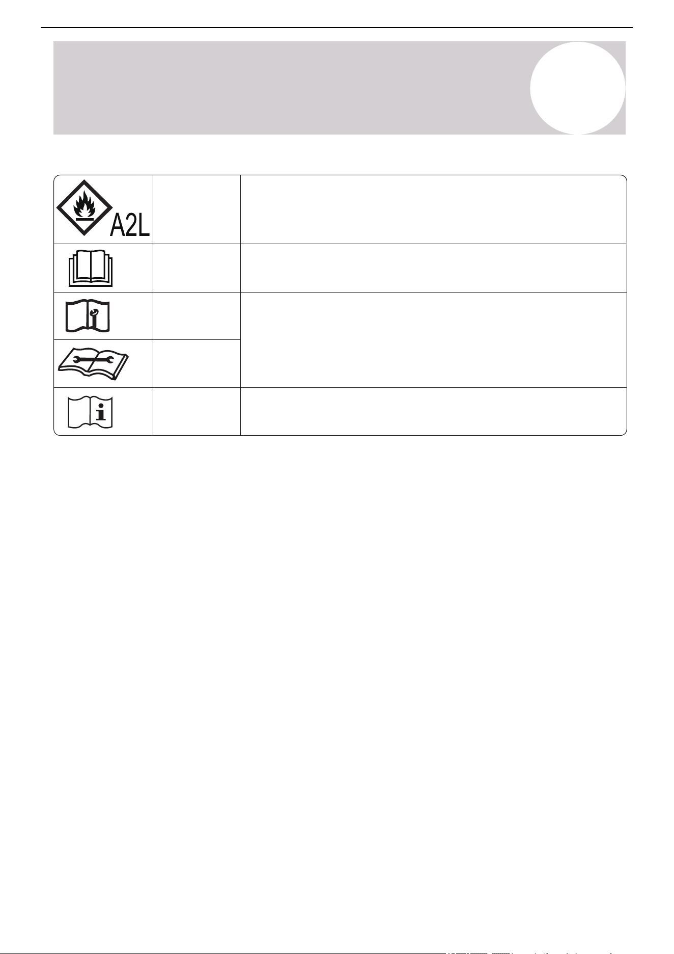
CAUTION
WARNING
This symbol shows that this appliance used a flammable
refrigerant. If the refrigerant is leaked and exposed to an
external ignition source, there is a risk of fire.
This symbol shows that the operation manual should be read
carefully.
This symbol shows that information is available such as the
operating manual or installation manual.
This symbol shows that a service personnel should be
handling this equipment with reference to this manual.
Explanation of symbols displayed on the indoor or outdoor units
CAUTION
CAUTION
CAUTION
17
Air Conditioner Installation & User Manual
Product Overview
2
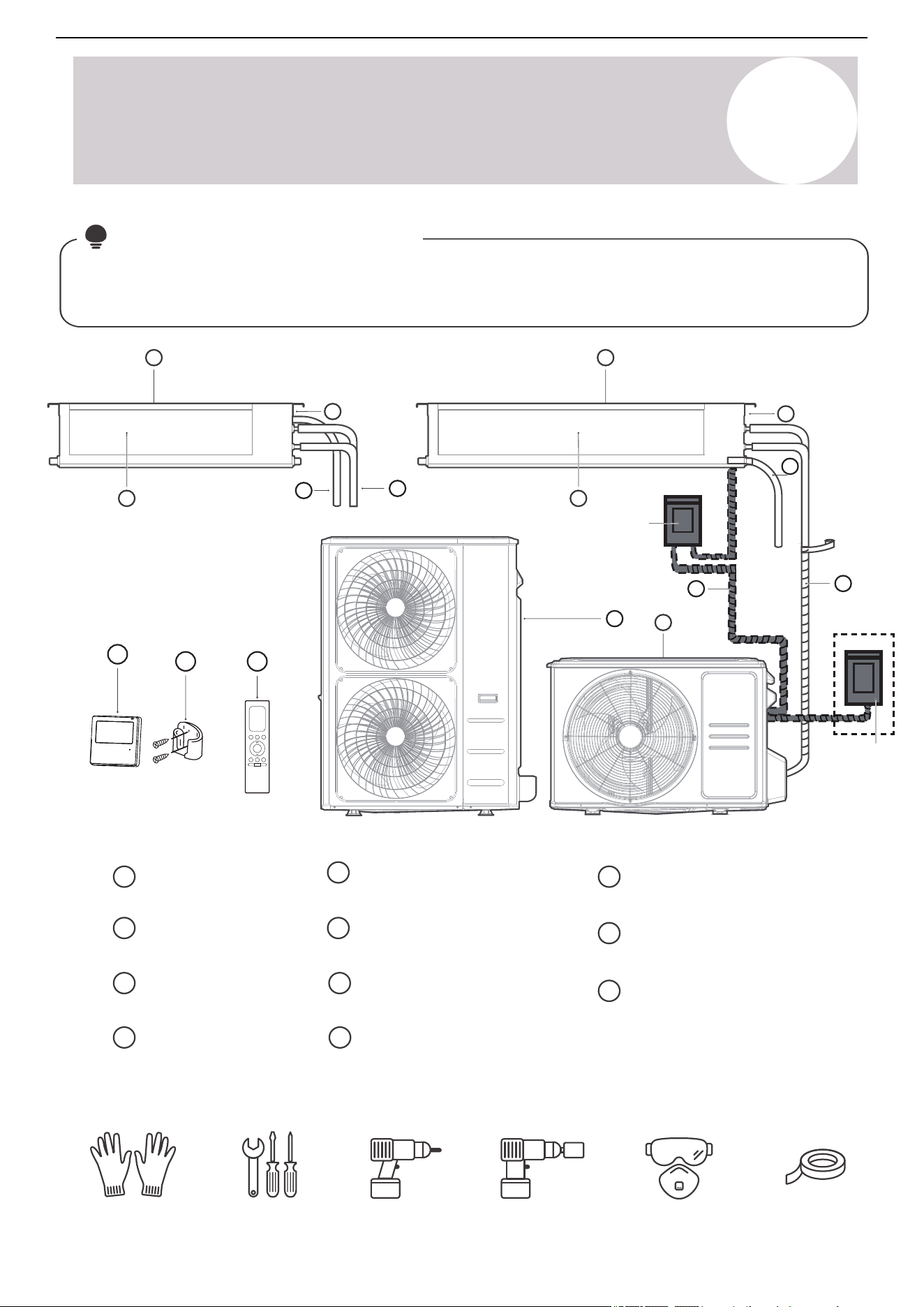
Note on Illustrations:
Illustrations in this manual are for explanatory purposes. The actual shape of the indoor unit may be slightly
different. The actual shape shall prevail. Perform the installation in accordance with the requirements of local
and national standards. The installation may be slightly different in different areas.
Refrigerant Piping
(purchase separately)
Outdoor Unit (A)
Outdoor Unit (B)
5
7
1
5
4
7
3
2
5
1
4
3
2
or
9
8
10
8
11
Air inlet
1
2
Air outlet
Electric control
box
Drain pipe
3
4
6
Connection cable
(purchase separately)
9
10
Wired remote controller
Remote Controller
(purchase separately)
Remote controller holder
(purchase separately)
Service
disconnect
6
Service
disconnect
Note: Select a service disconnect meeting the requirements of the local, regional, and national codes.
11
Gloves Screwdriver &
wrench
Goggles & masks Vinyl tape
It would be perfect to have these tools
Hammer
drill
Core drill
18
Note
Each time the air conditioner is powered on, a buzzing sound will be heard to indicate that the product has
been powered on normally. If there is no sound, it is possible that the unit is operating abnormally. Power
on the unit again or check the circuit.
The actual functions are subject to the product that was purchased. Check the indoor display and remote
control of the air conditioner.
See the Remote Controller manual for information on more features.
Air Conditioner Installation & User Manual
Product Overview
2
• Heat Exchanger Dust Removal
Function
This feature helps keep the outdoor coil
cleaner and may extend the duration between
regular maintenance intervals depending on
the local conditions. When the unit is turned
off, a 10-second delay occurs when the
outdoor fan runs in reverse rotation for 70
seconds to blow off loose accumulated dust
and debris.
• Refrigerant Leakage Detection
When the system detects a refrigerant
malfunction, the indoor unit will automatically
display the following error codes:
o EL0C - System lacks refrigerant.
o EHC1 - Refrigerant sensor detects
leakage.
o EHC2 - Working condition of the
refrigerant sensor is out of range and
leakage is detected.
o EHC3 - Working condition of the
refrigerant sensor is out of range.
o ECC1 - Other indoor unit refrigerant
sensor detects leakage (multi-zone
systems).
When EHC1 or EHC2 errors occur, the buzzer
will continue to beep for 5-6 minutes before
stopping. Pressing any button on the remote
control will also stop the buzzer.
Note: EHC1, EHC2, EHC3, and ECC1 error
codes are only applicable for units with
refrigerant sensors.
19
Air Conditioner Installation & User Manual
Product Installation
3
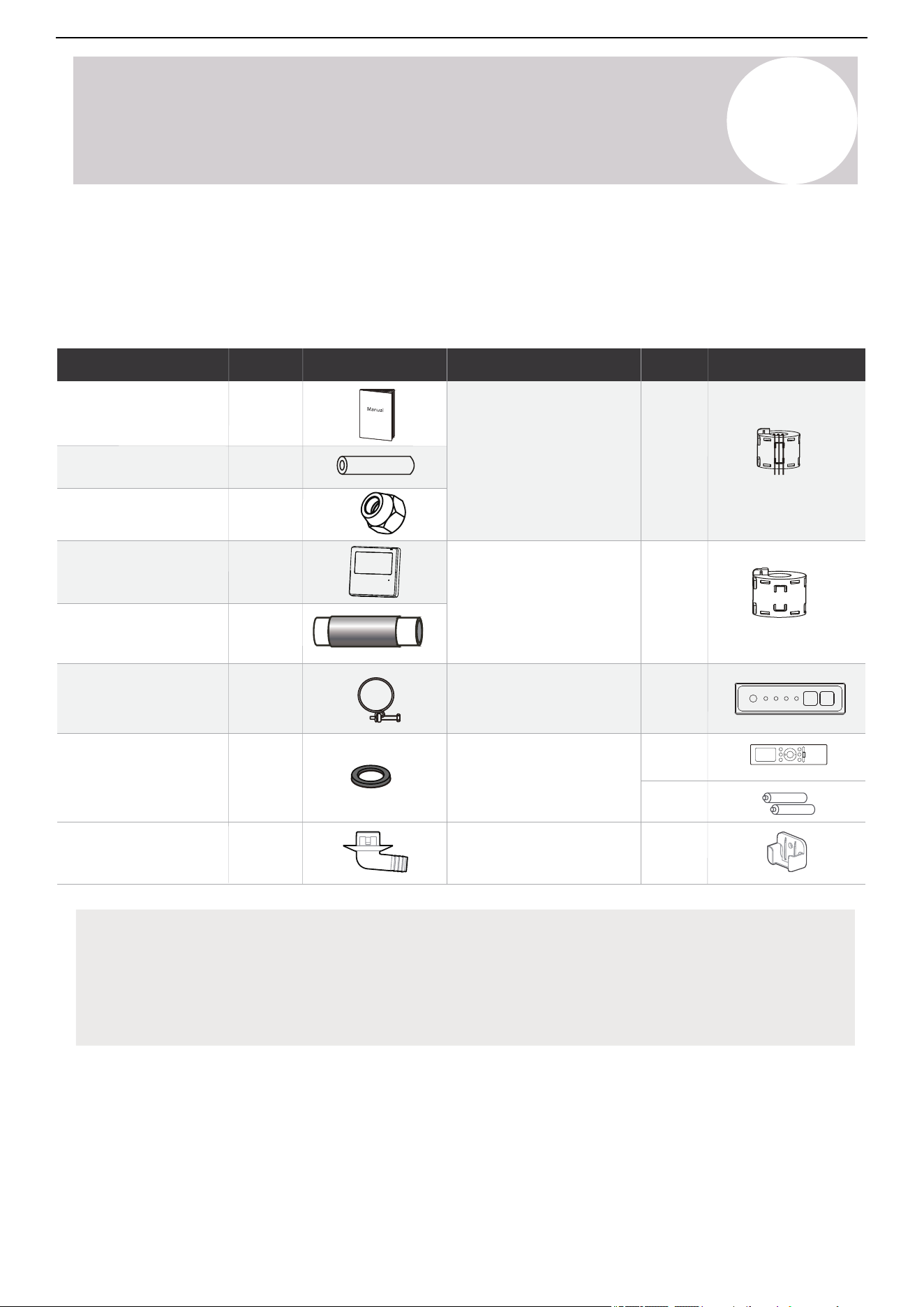
1
Magnetic ring
(Wrap the electric wires S1 &
S2 (P & Q & E) around the
magnetic ring twice)
Magnetic ring
(Hitch it on the connective
cable between indoor and
outdoor units after
installation.)
S1&S2 (P&Q&E)
Display panel 1
1
Manual
2~4
2
Refringent in/out pipe
protection cover
Copper nut
2
Outlet pipe clasp
1
1
Outlet pipe sheath
1
Wired remote controller
(with packing)
1
1
Remote controller & Battery
(purchase separately)
1
1
2
Remote controller holder
(purchase separately)
Drain joint
Seal ring
(Not available for the outdoor
unit with dimensions of 38.58
in x 38.39 in x16.34 in)
Name of Accessories
Qty
Shape
Name of Accessories
Qty
Shape
20
Accessories
The air conditioning system comes with the following accessories. Use all of the installation parts and
accessories to properly install the air conditioner. Improper installation may result in water leakage, electrical
shock and fire, or HTXLSPHQWIDLOXUH. The items that are not included with the air conditioner must be
purchased separately.
Optional Accessories
There are two types of remote controls: Wired and wireless.
Select a remote controller based on customer preferences and requirements. Install the remote control in an
appropriate place. Refer to catalouges and technical literature for guidance on selecting a suitable remote
controller.
Air Conditioner Installation & User Manual
Product Installation
3
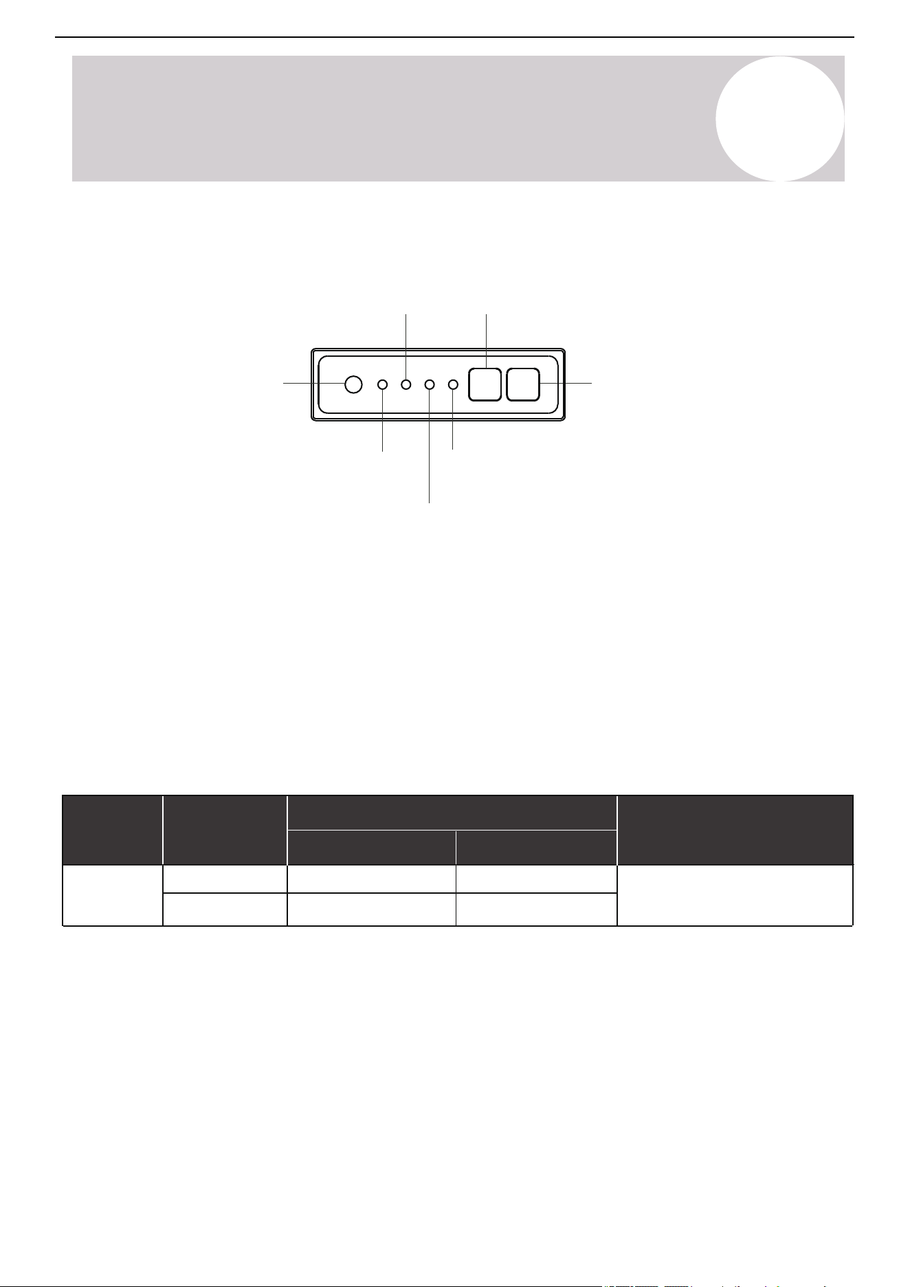
Display Panel
Timer
indicator
Infrared
receiver
Manual
button
LED
display
Operation
indicator
PRE-DEF
(pre-heating/defrost)
indicator
Alarm
indicator
Manual Button: This button selects the mode in the following order: Auto, Forced Cool, and Off.
Forced Cooling Mode: In Forced Cooling mode, the operation light flashes. The system will then turn to Auto
mode after it has cooled with a high wind speed for 30 minutes. The remote control will be disabled during this
operation.
Off Mode: When the display panel is turned off, the unit turns off and the remote control is re-enabled.
Size of Connecting Pipe
Parts you must purchase separately. Consult the dealer about the proper pipe size of the unit you purchased.
Liquid Side Gas Side
36K
48K
Connecting
pipe
assembly
Name Model
Pipe Specification
Remark
Pipes are not included in the accessories
and need to be purchased separately
from the local dealer.
Ø3/8 in (Ø9.52 mm)
Ø3/8 in (Ø9.52 mm)
Ø3/4 in (Ø19 mm)
Ø3/4 in (Ø19 mm)
21
Air Conditioner Installation & User Manual
Product Installation
3
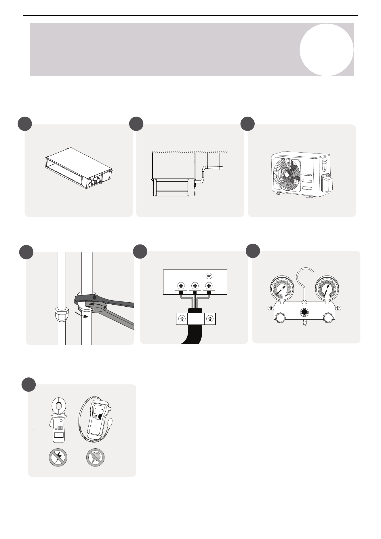
Installation Summary
Install the outdoor unit
Install the drain pipe
Install the indoor unit
1 2 3
Connect the refrigerant pipes
4
L1L1
Connect the wires
5
MC MC
Evacuate the refrigeration system
6
Perform a test run
7
22
Air Conditioner Installation & User Manual
Indoor Unit Installation
4
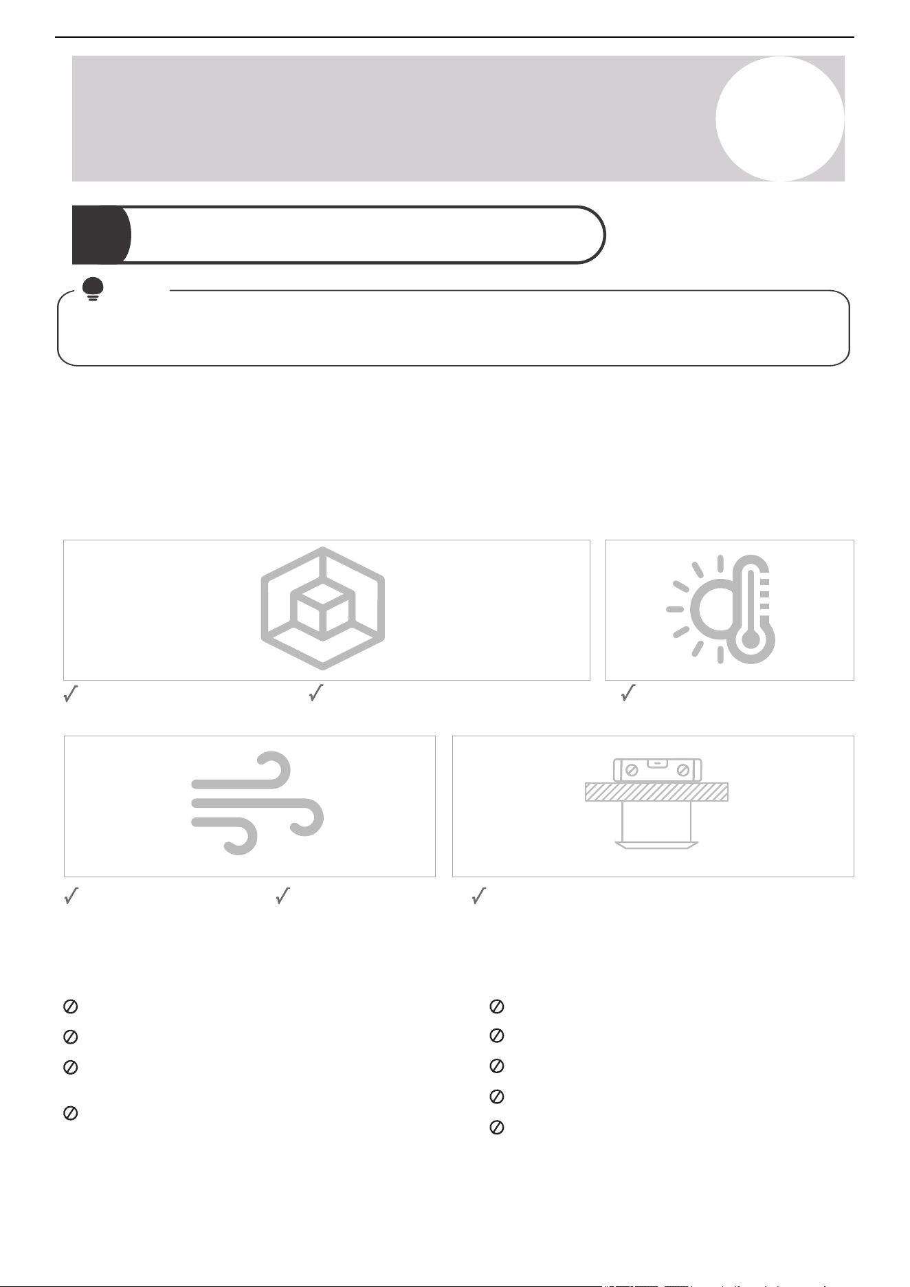
Select the Installation Location
1
Note:
Before installing the indoor unit, choose an appropriate location. The following are standards that will help
choose an appropriate location for the unit.
Before Installation:
• Determine the route for moving the unit to the installation site.
• First unseal and unpack the unit. Then, hold the seats of the hanger (4 pieces) to move the unit. Refrain
from exerting force on other parts of the unit, especially the refrigerant piping, water discharge piping, and
plastic parts.
Enough room exists for
installation and maintenance.
Enough room exists for connecting
the pipe and drainpipe.
The ceiling is horizontal and its structure can
sustain the weight of the indoor unit.
The air inlet and outlet
are not blocked.
The airflow can fill
the entire room.
There is no direct radiation
from heaters.
Proper installation locations must meet the following standards:
Areas with oil drilling or fracking
Coastal areas with high salt content in the air
Areas with caustic gases in the air, such as hot
springs
Areas that experience power fluctuations, such as
factories
Enclosed spaces, such as cabinets
Kitchens that use natural gas
Areas with strong electromagnetic waves
Areas that store flammable materials or gas
Rooms with high humidity, such as bathrooms or
laundry rooms
Do not install the unit in the following locations:
23
Air Conditioner Installation & User Manual
Indoor Unit Installation
4
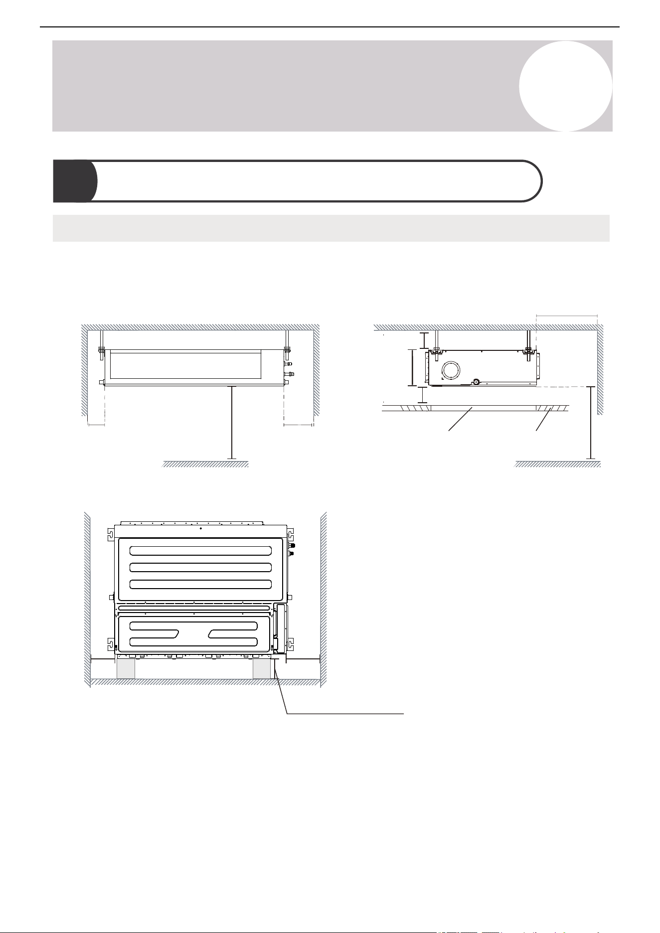
Confirm Installation Sizes
2
Installation Place
The distance between the mounted indoor unit must meet the specifications illustrated in the following diagram:
Left
side
Right
side
Strong and durable ceiling
Indoor unit
>7.9in
(200 mm)
>11.8in
(300 mm)
>0.8 in (20 mm)
>0.8 in (20 mm)
>11.8in
(300 mm)
FloorFloor
Floor
Service access Ceiling
B
>90.6in (2.3 m)
1) Ceiling-mounted
2) Wall-mounted
23.6~70.9 in (0.5~1.8 m)
>90.6 in (2.3 m)
≥15.7 in (399 mm)
≥23.6 in (599 mm)
24
Air Conditioner Installation & User Manual
Indoor Unit Installation
4
Maintenance Space
Air outlet
Air inlet
≥7.9 in
(201 mm)
≥11.8 in
(300 mm)
31.5 in x 31.5 in (800 mm x 800 mm)
Checking orifice
3
Hang the Indoor Unit
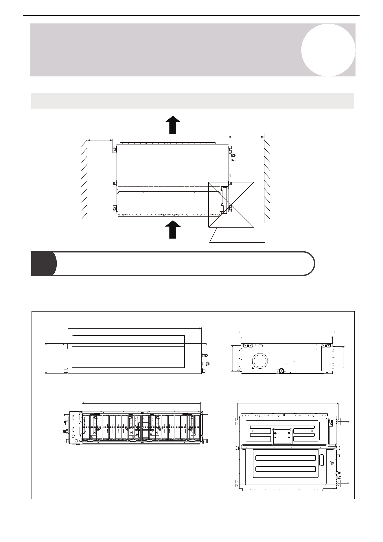
Air Outlet Dimensions
Air Inlet Dimensions
B
A
E
G
I
J
C
H
F
D
Refer to the following diagrams to locate the four positioning screw bolt holes on the ceiling. Be sure to mark the
places where to drill ceiling hook holes.
25
Air Conditioner Installation & User Manual
Indoor Unit Installation
4
OUTLINE DEMENSION
AIR OUTLET
OPENING SIZE
AIR RETURN
OPENING SIZE
SIZE OF
MOUNTED LUG
A B C D E F G
H
I
J
MODEL
36K/48K
47.2/1200 11.8/300 29.5/750 31.3/795 48.8/1240 25.2/64040.4/1027 9.2/233 43.0/1092 10.5/267
(unit: inch/mm)
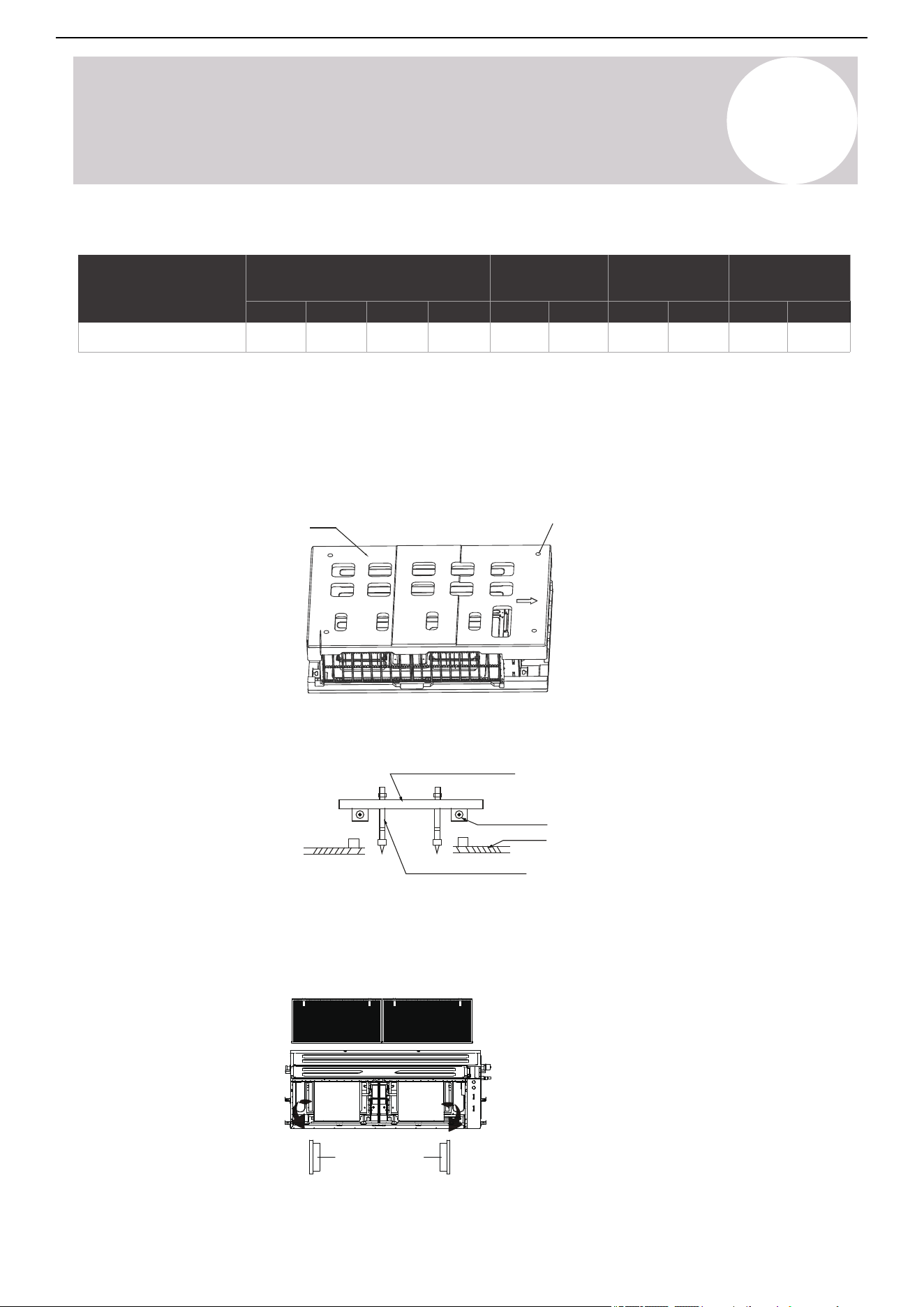
Ceiling Bolt Installation Guidelines
1) Wood
The mounting holes for the upper foam are used for auxiliary positioning bolts (if the foam is damaged, the
spacing between the actual lifting lugs should be the standard).
Upper foam Installation locating hole
Place the wood mounting across the roof beam, then install the hanging screw bolts.
Wood mounting
Roof beam
Hanging screw bolts
Ceiling
2) Take Out the Pearl Cottons (Only for 60K Units)
1. Remove the air inlet channel panel.
2. Take out two pearl cottons.
Air inlet channel panel
Pearl cotton
26
Air Conditioner Installation & User Manual
Indoor Unit Installation
4
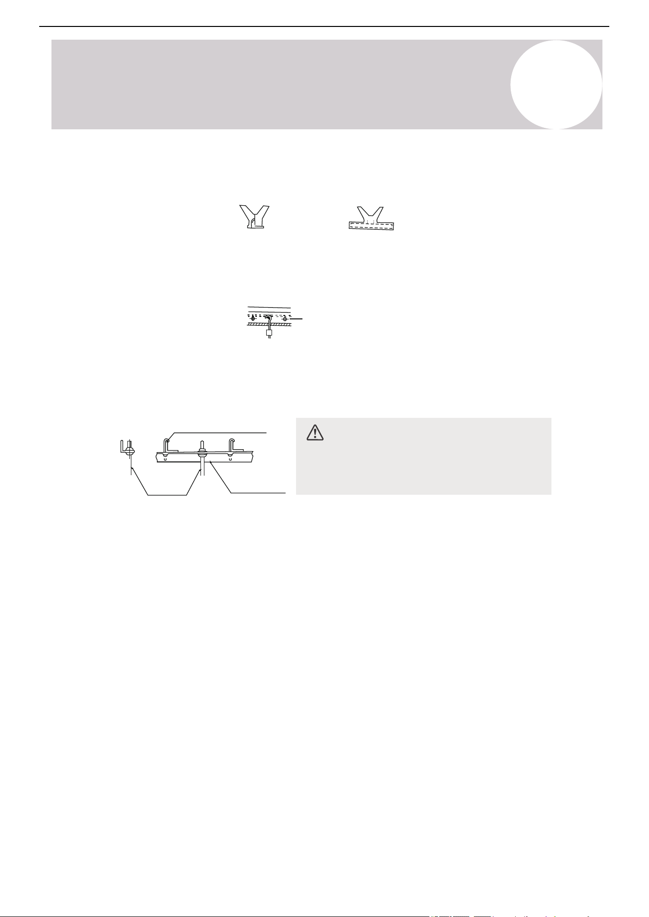
3) New Concrete Bricks
Inlay or embed the screw bolts.
(Blade shape insertion)
(Slide insertion)
4) Original Concrete Bricks
Use an embedding screw bolt, crock, and stick harness.
Steel bar
Embedding screw bolt
(Pipe hanging and embedding screw bolt)
5) Steel Roof Beam Structure
1. Install and use the supporting steel angle.
Hanging screw bolt
Hanging
bolts
Supporting
angle steel
CAUTION
Completely align the unit body with the hole.
Ensure that the unit and hole are the same size
before moving on.
2. Install and fit pipes and wires after finishing the installation of the main body. When choosing where to start,
determine the direction of the pipes to be drawn out. Especially in cases where is a ceiling involved, align the
refrigerant pipes, drain pipes, and indoor and outdoor lines with their connection points before mounting the unit.
3. Install the hanging screw bolts.
• Cut off the roof beam.
• Strengthen the point at which the cut was made. Consolidate the roof beam.
4. After selecting an installation location, align the refrigerant pipes, drain pipes, and the indoor and outdoor wires
with their connection points before mounting the unit.
5. Drill four holes 4 inches deep at the ceiling hook positions into the internal ceiling. Be sure to hold the drill at a
90° angle to the ceiling.
6. Secure the bolt using the washers and nuts provided.
7. Install the four suspension bolts.
27
Air Conditioner Installation & User Manual
Indoor Unit Installation
4
8. Mount the indoor unit with at least two people to lift and secure it. Insert suspension bolts into the unit's
hanging holes. Fasten them using the washers and nuts provided.
9. Position the indoor unit flat using a level indicator to prevent leaks.
Screw nut
Washer
Hanging screw bolt
Overhang part
Shockproof cushion
Note: Confirm the minimum drain tilt is 1/100 or
more.
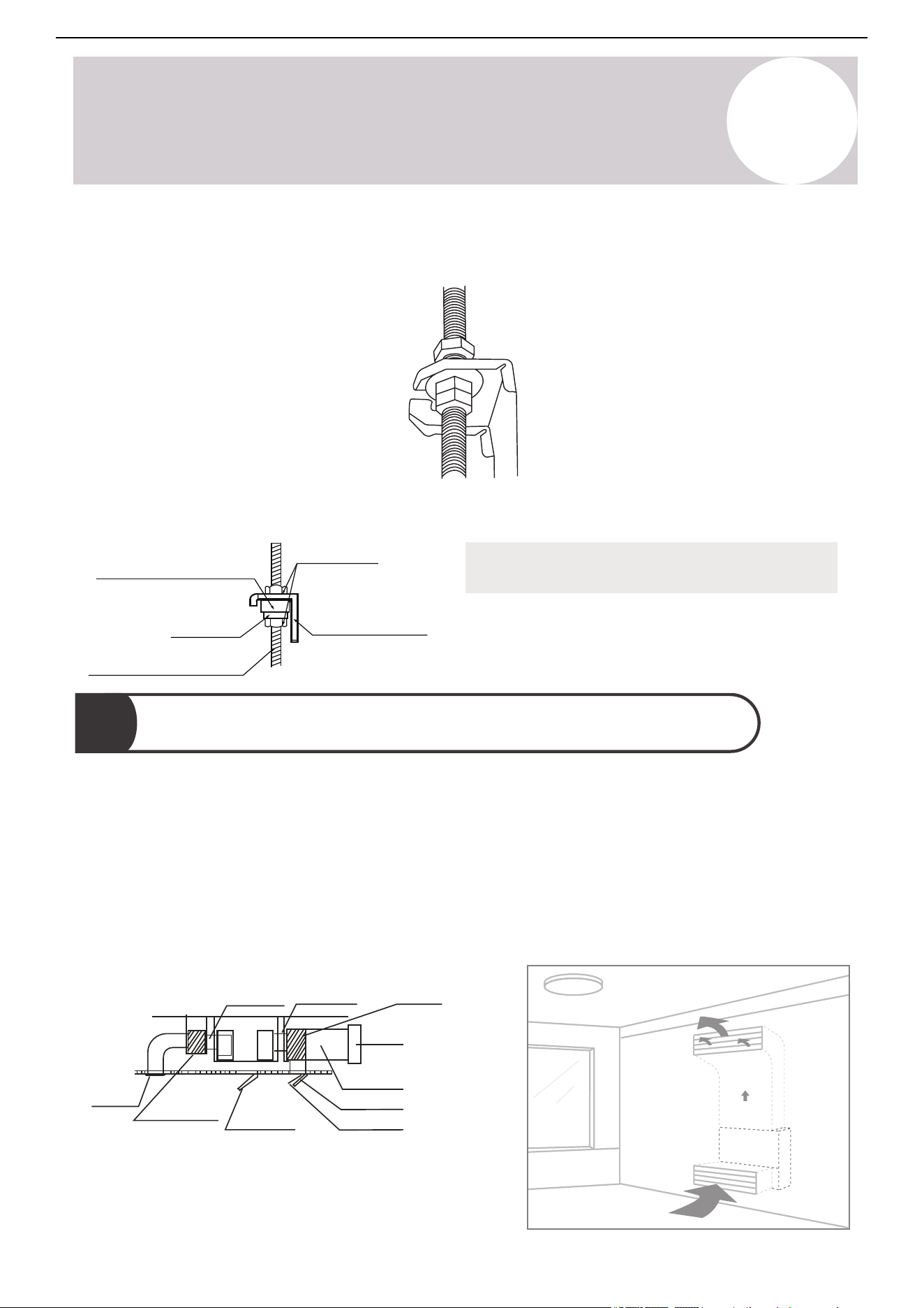
4
Duct & Accessories Installation
Duct
1. Install the filter according to the size of the air inlet.
2. Install the canvas tie-in between the body and duct.
3. The air inlet and outlet ducts must be far enough apart to avoid an air passage short-circuit.
4. Connect the duct according to the following diagrams:
Canvas tie-in Canvas tie-in
Air outlet
Isolation
booth
Isolation booth
Grille
Duct
Checking
orifice
Air inlet
Air dust filter
Ceiling-Mounted
Wall-Mounted
28
Air Conditioner Installation & User Manual
Indoor Unit Installation
4
Notes:
• The minimum length of the duct should be more than 3.3 feet (1 m). Fix on the air inlet and outlet using
screws (applicable to the unit that the air inlet and outlet filter is not fastened by screws). If fixing the air inlet
and outlet using screws is not available, the inlet and outlet needs to be installed with a grille, which needs to
be fixed to the air duct with screws.
• Do not place the weight of the connecting duct on the indoor unit.
• When connecting the duct, use a nonflammable canvas tie-in to prevent vibrating.
• Wrap the insulation foam outside the duct to avoid condensate. Add an internal duct underlayer to reduce
noise, if the end-user requires.
• When the machine is wall-mounted, the machine should be concealed mounted and the air inlet and outlet
should be installed with a grille. Fix the grille firmly with the screws.
CAUTION
Ensure that no part of the human body touches any internal components of the equipment after installation.
Wall-Mounted Installation
Note: Wall mounted installation is not suitable for models with this box size:
A=1400, B=380, C=800 and A=1200, B=300, C=750 (refer to the table on page 18).
The unit supports wall mounted installation. If the unit is purchased with a pump and requires vertical mounting,
follow the steps below:
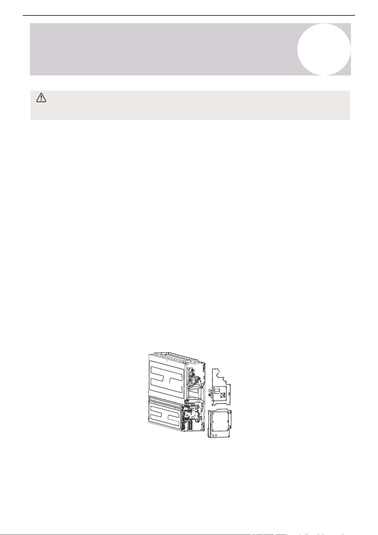
1. Remove the electrical control box cover, then unplug the pump and water level switch terminals from the
main control board.
2. Disassemble the pump components.
29
Air Conditioner Installation & User Manual
Indoor Unit Installation
4
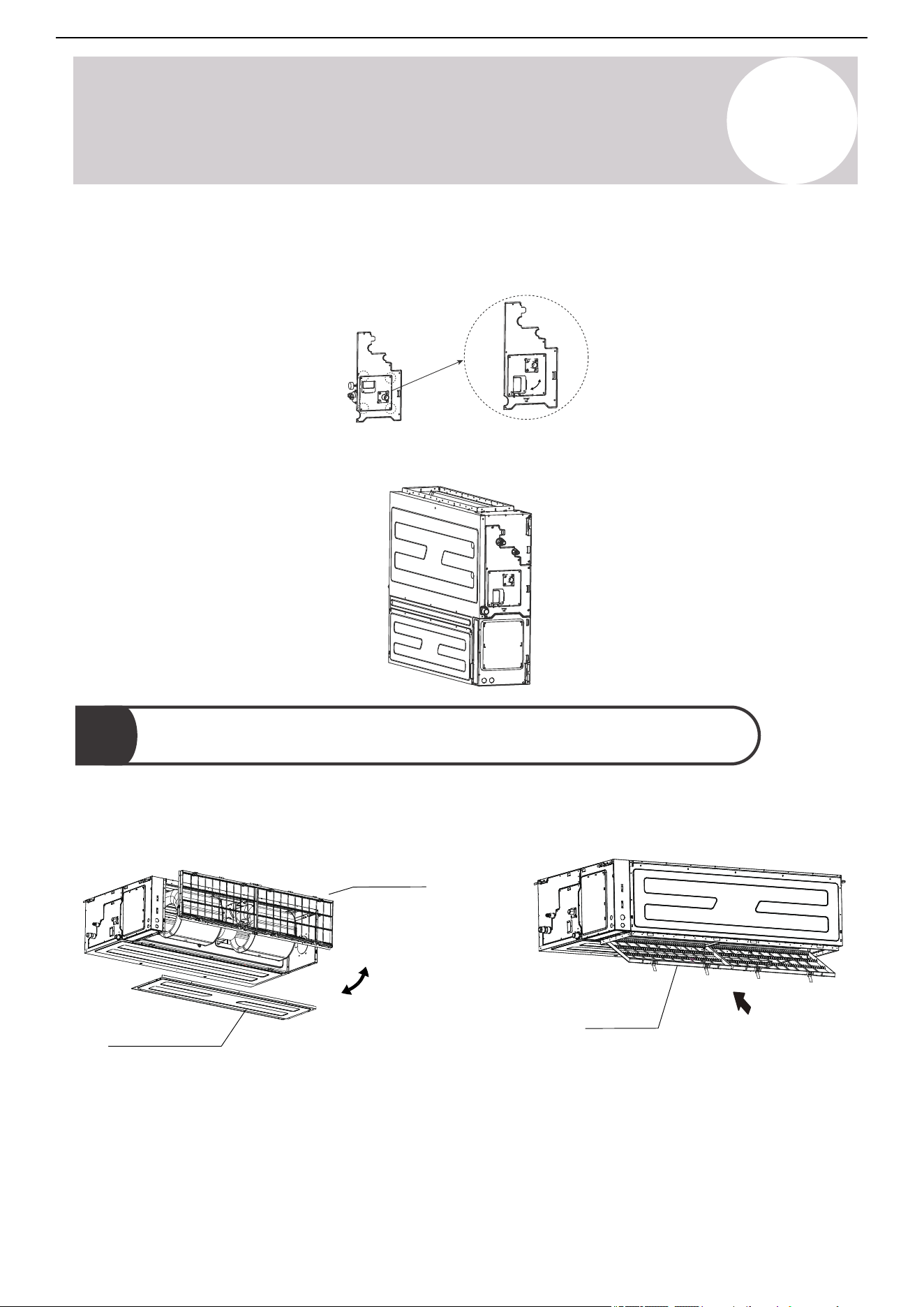
3. Remove the four screws, then remove the water pump components by 90° degrees. Fix the screws to the
water pump mounting plate again.
4. Install the pump parts to the machine and connect the wiring set.
5
Filter Installation
1. The duct is set to rear return air by default, and can be modified to bottom return air as needed. Take off the
ventilation panel, flange, and air filter. Then, change the mounting positions of the ventilation panel and air return
flange.
Flange and Air filter
Ventilation panel
Air filter
30
Air Conditioner Installation & User Manual
Indoor Unit Installation
4
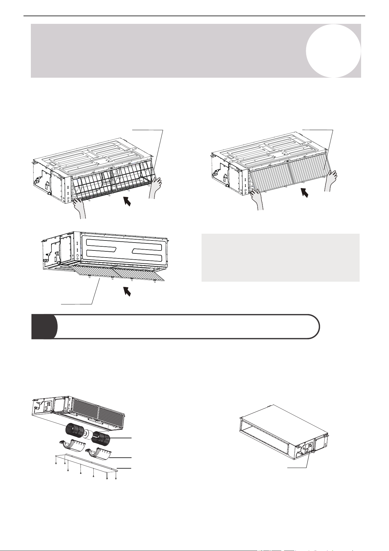
2. When installing the filter mesh, fit it into the flange.
Air filter
Air filter
Air filter
Note:
All the figures in this manual are for demonstration
purposes only. The air conditioner you have
purchased may be slightly different in design,
though similar in shape.
Motor and drain pump maintenance
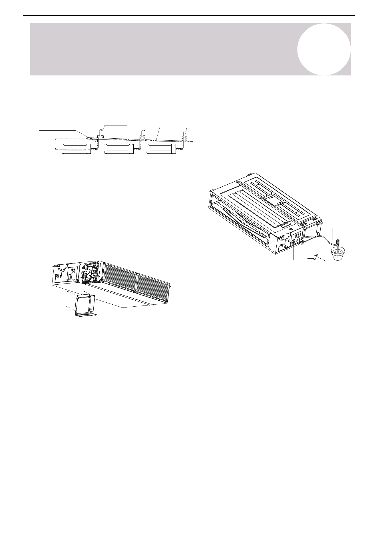
(The rear ventilated panel is used as an example)
6
1) Motor Maintenance:
1. Take off the ventilated panel.
2. Take off the blower housing.
3. Take off the motor.
Motor
Blower housing
Ventilated panel
2) Pump Maintenance:
1. Remove four screws from the drain pump.
2. Unplug the pump power supply and water level
switch cable.
3. Detach the pump.
Pump
31
Air Conditioner Installation & User Manual
Indoor Unit Installation
4
Indoor Drainpipe Installation
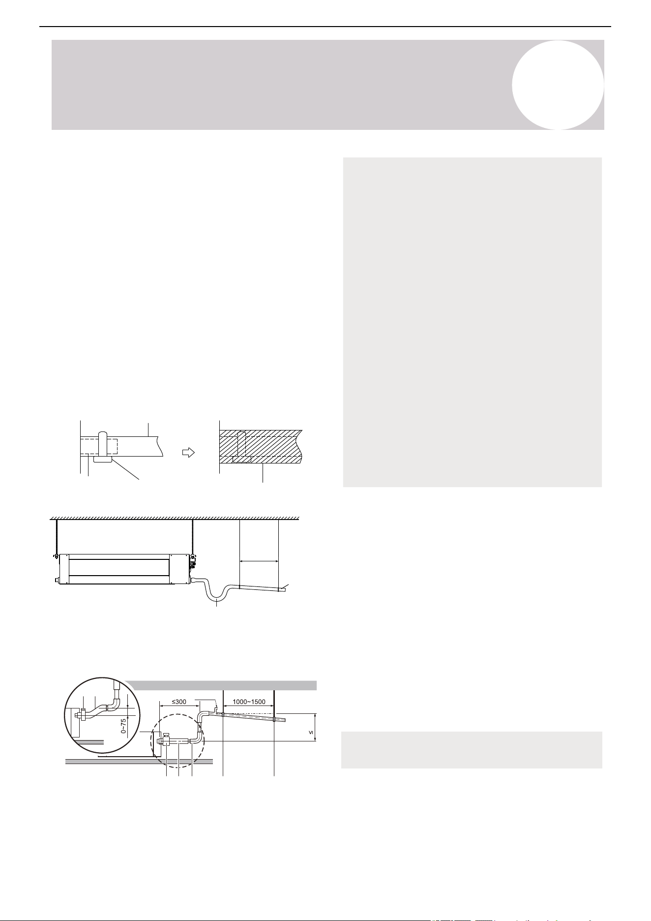
Install the drainpipe as illustrated in the following
figure.
1. Cover the drainpipe with heat insulation to prevent
condensation and leakage.
2. Attach the mouth of the drain hose to the unit's
outlet pipe. Sheath the mouth of the hose and clip it
firmly with a pipe clasp.
3. These units operate with a negative pressure at
the drain connections. A drain trap is required. The
trap needs to be installed as close to the unit as
possible. Make sure the top of the trap is below the
connection to drain pan, allowing complete drainage
of the pan.
(Ceiling-mounted)
Drainpipe
connecting port
Drain hose
Pipe clasp
Insulation
Lean over 1/50
Ceiling
U type tube
39-59 in
(1-1.5 m)
Note on Drainpipe Installation
• When using an extended drainpipe, tighten the
indoor connection with an additional protection
tube. This prevents it from pulling loose.
• The drainpipe should slope downward at a
gradient of at least 1/100 to prevent water from
flowing back into the air conditioner.
• To prevent the pipe from sagging, space
hanging wires every 39-59 inches (1-1.5 m).
• If the outlet of the drainpipe is higher than the
body's pump joint, use a lift pipe for the indoor
unit's exhaust outlet. Install the lift pipe no
higher than 21.7 inches (551 mm) from the
ceiling board. The distance between the unit
and lift pipe must be less than 7.9 inches (201
mm). Incorrect installation could cause water to
flow back into the unit and flood.
• To prevent air bubbles, keep the drain hose
level or slightly titled up (< 3 in / 75 mm)
Drainpipe Installation for Units with a Pump
(mm)
a b
dda b c
1000
Air vent
a: Metal clamp (accessory)
b: Drain hose (accessory)
c: Rising drain piping (vinyl pipe of 25 mm nominal
diameter and 32 mm outer diameter) (field supply)
d: Hanging bars (field supply)
Note: When connecting multiple drainpipes, install
the pipes as illustrated.
33
Air Conditioner Installation & User Manual
Indoor Unit Installation
4
Units with a Pump
Air vents are not allowed in
lifting section
Air vent (Each indoor unit
must have a vent)
39.4 in
(0-1,000 mm)
Air vent Air vent
Incline 1/50
To Check for Water Leaks
The procedure differs depending on whether
the electrical wiring is already finished. When
the electrical wiring is not finished yet,
temporarily connect the user interface and
power supply to the unit.
When Electrical Wiring is Not Finished Yet
1. Temporarily connect the electrical wiring.
2. Remove the switch box cover (a).
3. Connect the single-phase power supply (50hz, 230V)
to connections No. 1 and No. 2 on the terminal block for
power supply and earth.
4. Reattach the switch box cover (a).
5. Turn on the power.
6. Start the cooling operation.
7. Gradually pour approximately 1 liter of water through
the air discharge outlet, then checks for leaks.
f
b
c
e
d
a
a. Water inlet | b. Portable pump | c. Water inlet cover
d. Bucket (adding water through water inlet)
e. Drain outlet for maintenance | f. Refrigerant pipes
8. Turn off the power.
9. Disconnect the electrical wiring.
10. Remove the control box cover.
11. Disconnect the power supply and earth.
12. Reattach the control box cover.
When Electrical Wiring is Finished Already
1. Start cooling operation.
2. Gradually pour approximately 1 liter of water through
the air discharge outlet, then checks for leaks.
34
Air Conditioner Installation & User Manual
Outdoor Unit Installation
5
Select the Installation Location
1
Note: Prior to Installation
Before installing the outdoor unit, choose an appropriate location. The following are standards intended to help
select an appropriate location for the unit.
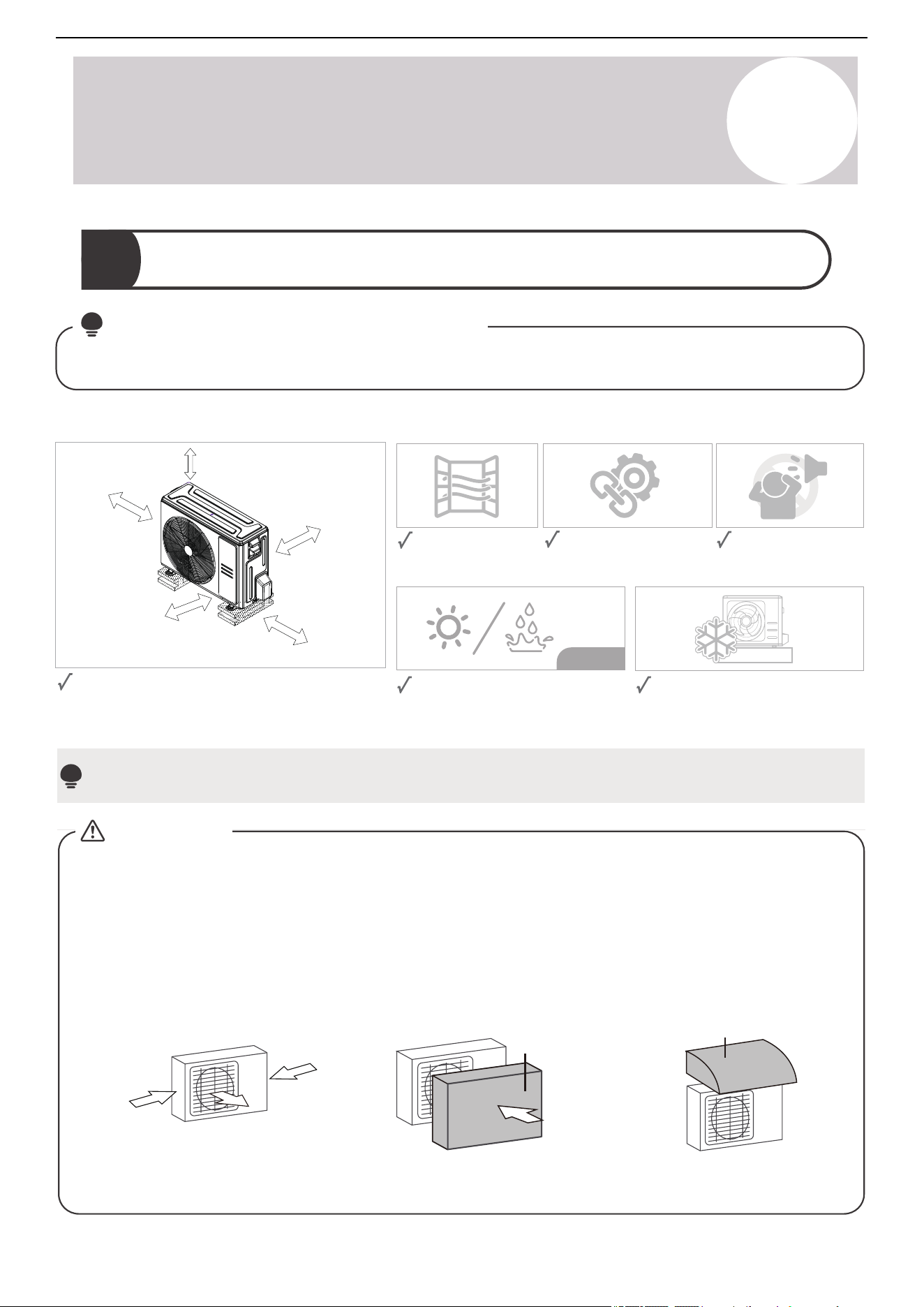
Proper installation locations must meet the following standards:
Firm and solid—the
location can support the
unit and will not vibrate.
Protected from prolonged periods of
direct sunlight or rain.
Where snowfall is anticipated, take
appropriate measures to prevent ice
buildup and coil damage.
Good air circulation
and ventilation.
Noise from the unit will
not disturb other
people.
Long-term
Meets all spatial requirements shown in the
installation clearance requirements above.
20 in (500mm) or more when front and
sides of the unit are clear
20 in (500 mm) or more
when any 2 sides of left,
right, and rear of the
unit are clear.
14 in (350 mm)
or more
4 in (100 mm)
or more
4 in (100 mm)
or more
Note:
Install the unit by following local codes and regulations, which can differ slightly between different regions.
Strong
wind
Strong
wind
Strong
wind
Wind Baffle
90° angle to the direction of
the wind
Build a wind baffle to
protect the unit
Build a shelter to protect
the unit
CAUTION:
Shelter
Special Considerations for Extreme Weather
If the unit is exposed to heavy wind:
Install the unit so that the air outlet fan is at 90° angle to the direction of the wind. If needed, build a barrier in
front of the unit to protect it from extremely heavy winds. See the figures below:
If the unit is frequently exposed to heavy rain or snow:
Build a shelter above the unit to protect it from rain or snow. Be careful not to obstruct air flow around the unit.
If the unit is frequently exposed to salty air (seaside):
Use an outdoor unit that is specially designed to resist corrosion.
35
Air Conditioner Installation & User Manual
Outdoor Unit Installation
5
Do not the install the unit in the following locations:
Near an obstacle that will block
air inlets and outlets.
Near public streets, crowded
areas, or where noise from the
unit will disturb others.
Near animals or plants
that will be harmed by
hot air discharge.
Near any source of
combustible gas.
In a location that is exposed to
large amounts of dust.
In a location exposed to an
excessive amount of salty air.
2
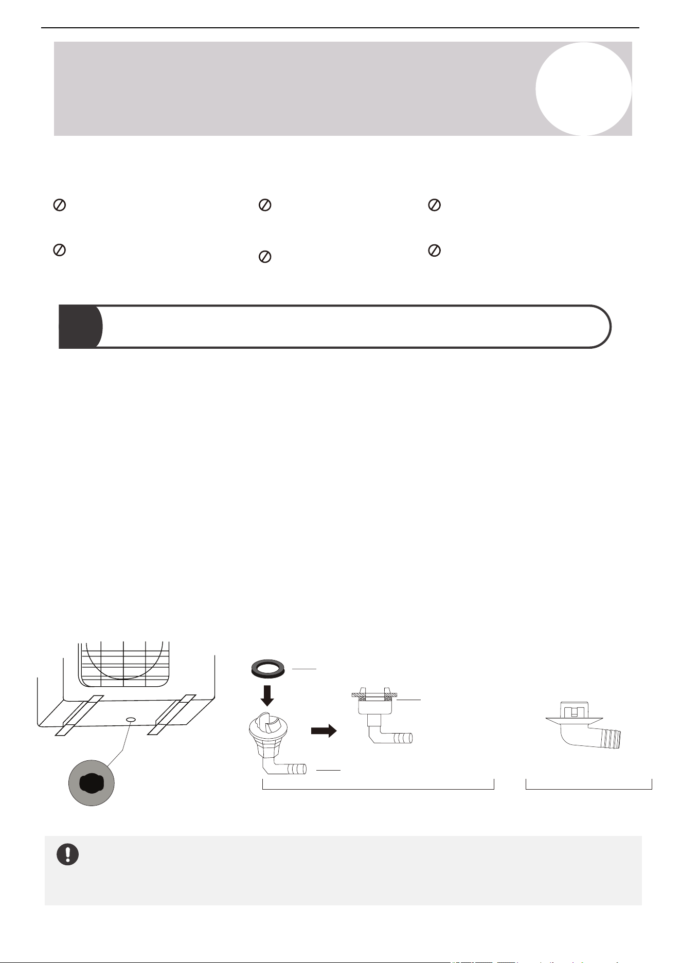
Install the Drain Joint (Heat Pump Unit Only)
Before bolting the outdoor unit in place, install the drain joint at the bottom of the unit.
Note: There are two different types of drain joints depending on the type of outdoor unit.
If the drain joint comes with a rubber seal (Figure A), do the following:
1. Fit the rubber seal on the end of the drain joint that will connect to the outdoor unit.
2. Insert the drain joint into the hole of the unit's base pan.
3. Rotate the drain joint 90° until it clicks into place facing the front of the unit.
4. Connect a drain hose extension (not included) to the drain joint in order to redirect water from the unit during
Heating mode.
If the drain joint does not come with a rubber seal (Figure B), do the following:
1. Insert the drain joint into the hole of the base pan, then press firmly to ensure it is properly installed and does
not become loose.
2. Connect a drain hose extension (not included) to the drain joint in order to redirect water from the unit during
Heating mode.
In Cold Climates
In cold climates, make sure that the drain hose is as vertical as possible to ensure swift water drainage. If water
drains too slowly, it can freeze in the hose and flood into the unit.
Base pan hole of
the outdoor unit
Seal
Seal
Drain joint
(A) (B)
36
Air Conditioner Installation & User Manual
Outdoor Unit Installation
5
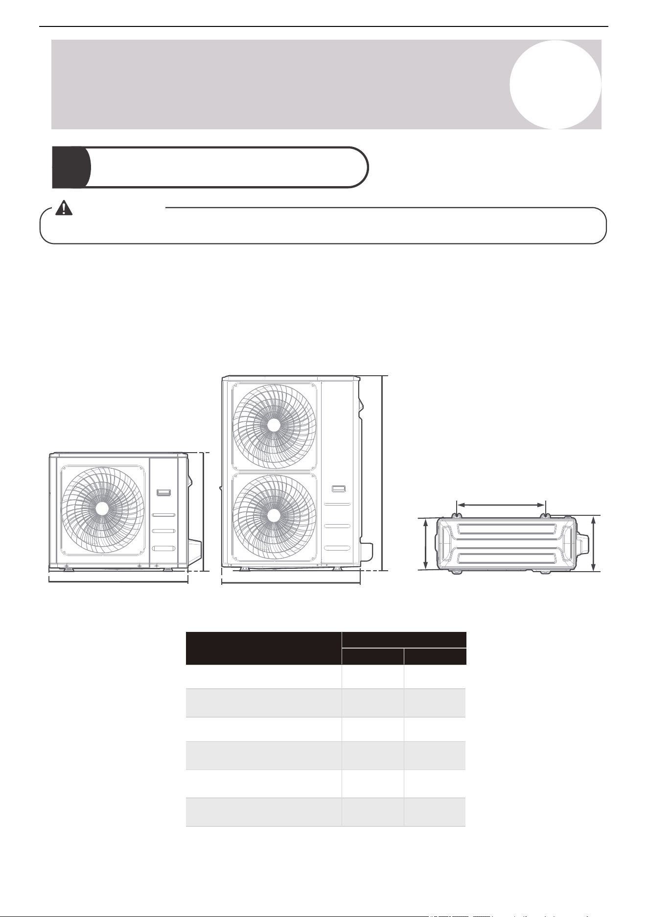
3
Anchor the Outdoor Unit
WARNING
When drilling into concrete, eye protection is recommended at all time.
Anchor the outdoor unit to the ground or a wall-mounted bracket with bolts (M10). Prepare the installation base
of the unit according to the dimensions below.
The following is a list of different outdoor unit sizes and the distance between their mounting feet. Prepare the
installation base of the unit according to the dimensions below.
Outdoor Unit Types & Specifications (Split Type Outdoor Unit)
W
H
W
H
D
A
B
Front View Top View
26.5 in
(673 mm)
15.87 in
(403 mm)
15.9 in
(404 mm)
24.25 in
(616 mm)
15.63 in
(397 mm)
17.8 in
(452 mm)
11.3 in
(286 mm)
20.1 in
(511 mm)
12.5 in
(317 mm)
Mounting Dimensions
Distance A Distance B
26.1 in
(663 mm)
13.9 in
(354 mm)
24.96 in
(634 mm)
30.1 in x 21.8 in x 11.9 in
(765 mm x 555 mm x 303 mm)
31.7 in x 21.8 in x 12.9 in
(
805 mm x 555 mm x 330 mm)
35.0 in x 26.5 in x 13.5 in
(
890 mm x 673
mm x 3
42
mm)
37.24 in x 31.9 in x 16.53 in
(
946 mm x 810
mm x
420
mm)
38.58 in x 38.39 in x 16.34 in
(
980 mm x 975
mm x
415
mm)
37.5 in x 52.5 in x 16.34 in
(952 mm x 1,333
mm x 415 mm)
Outdoor Unit Dimensions
W x H x D
37
Air Conditioner Installation & User Manual
Outdoor Unit Installation
5
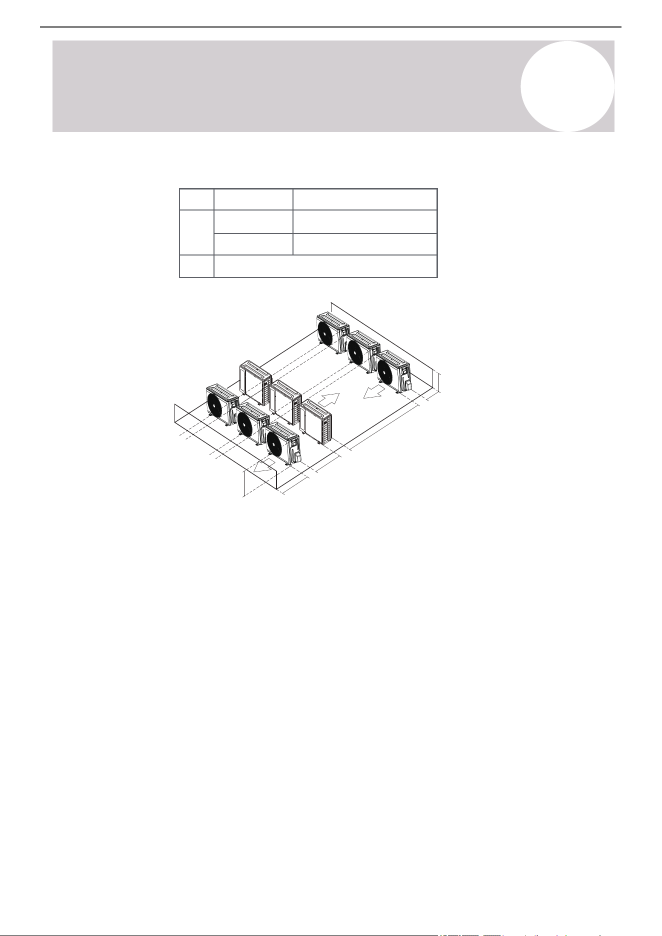
Rows of Series Installation
L ≤ H
L ≤ 1/2H
L A
9.8 in (248.9 mm) or more
1/2H < L ≤ H
11.8 in (299.7 mm) or more
L > H
Cannot be installed
L
118in (300cm) or more
A
23.6in (60cm)
or more
59in (150cm)
or more
or more
or more
n (25
9.8in (25cm)
9.8i cm)
H
Note:
H: Unit height
L: Height of the wall behind the unit
A: Distance between the unit and wall
38
Air Conditioner Installation & User Manual
Refrigerant Piping Connection
6
When connecting the refrigerant piping, do not let substances or gases other than the specified refrigerant from
entering the unit. The presence of other gases or substances will lower the unit's capacity, and can cause
abnormally high pressure in the refrigeration cycle. This can cause an explosion and injury.
Notes on Pipe Length & Elevation
Model
Length of Piping Maximum Drop Height
36K/48K 246 ft / 75 m
98.4 ft / 30 m
Maximum Length & Drop Height Based on Models
Ensure that the length of the refrigerant pipe, number of bends, and drop height between the indoor and outdoor
units meet the requirements shown in the table:
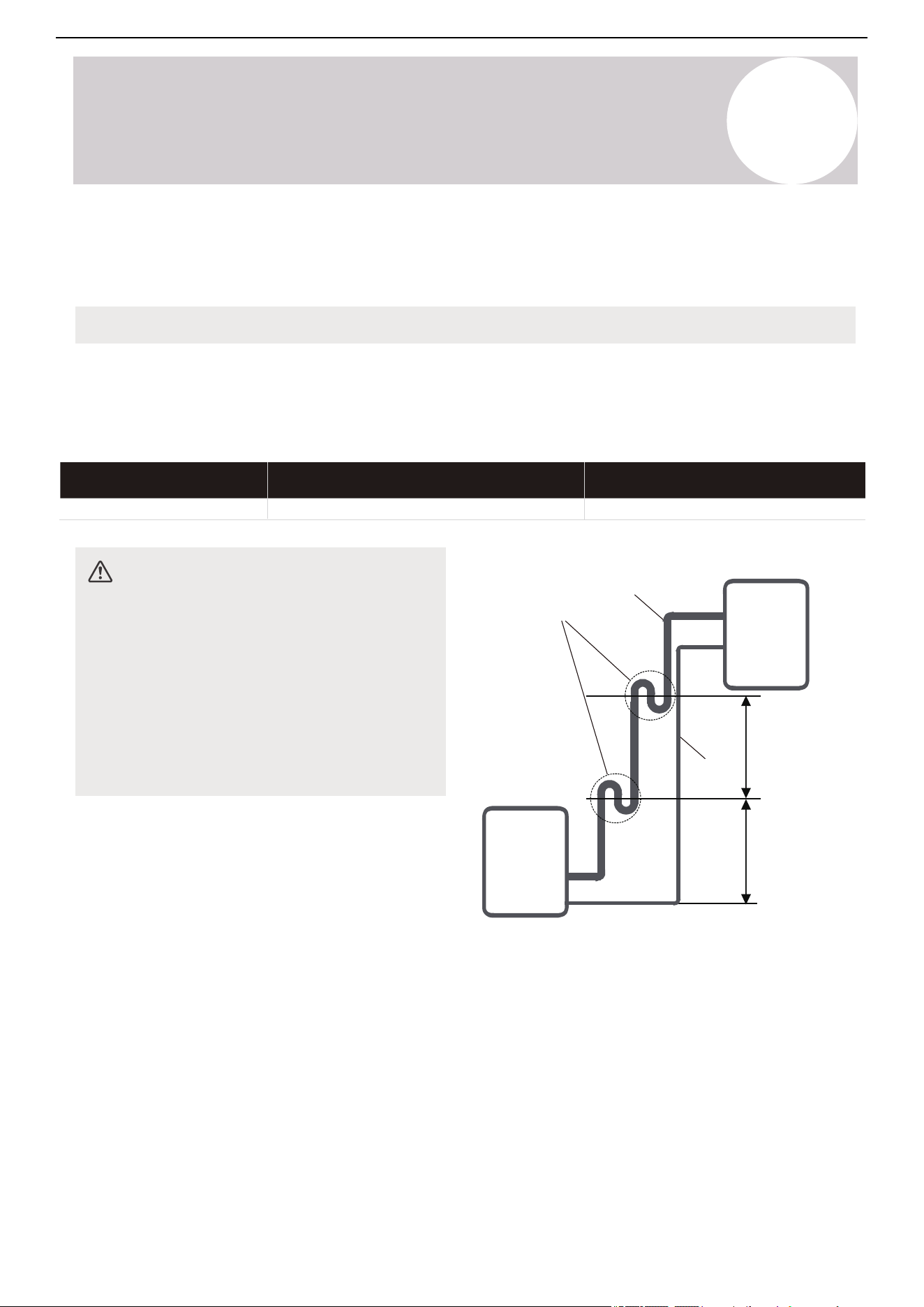
CAUTION
Oil Traps
If oil flows back into the outdoor unit's
compressor, this might cause liquid compression
or deterioration of oil return. Oil traps in the rising
gas piping can prevent this.
Install an oil trap every 20 feet (6 m) of vertical
suction line riser (<36K). Install an oil trap every
32.8 feet (10 m) of vertical suction line riser
(≥36K).
Indoor unit/
Outdoor unit
Oil trap
Gas piping
Indoor unit/
Outdoor unit
Liquid
piping
20 ft/6 m
(<36K)
32.8 ft/10 m
(≥36K)
20 ft/6 m
(<36K)
32.8 ft/10 m
(≥36K)
39
Air Conditioner Installation & User Manual
Refrigerant Piping Connection
6
Connection Instructions - Refrigerant Piping
CAUTION
• Install the branching pipe horizontally. An angle of more than 10° may cause malfunctions.
• Do not install the connecting pipe until both the indoor and outdoor units have been installed.
• Insulate both gas and liquid piping to prevent condensation.
Oblique Rough Warped
90°
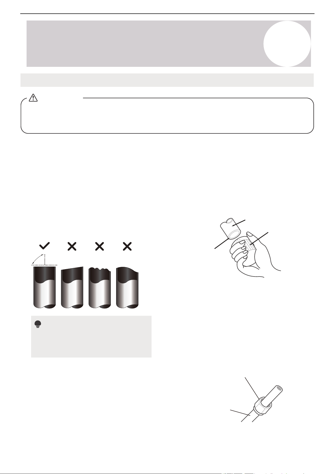
Step 1: Cut Pipes
When preparing the refrigerant pipes, take extra care
to cut and flare them properly. This will ensure
efficient operation and minimize the need for future
maintenance.
Do Not Deform the Pipe While Cutting
Be careful not to damage, dent, or deform the
pipe while cutting. This will drastically reduce
the heating efficiency.
40
1. Measure the distance between the indoor and
outdoor units.
2. Use a pipe cutter to cut the pipe a little longer than
the measured distance.
3. Make sure that the pipe is cut at a perfect 90°
angle.
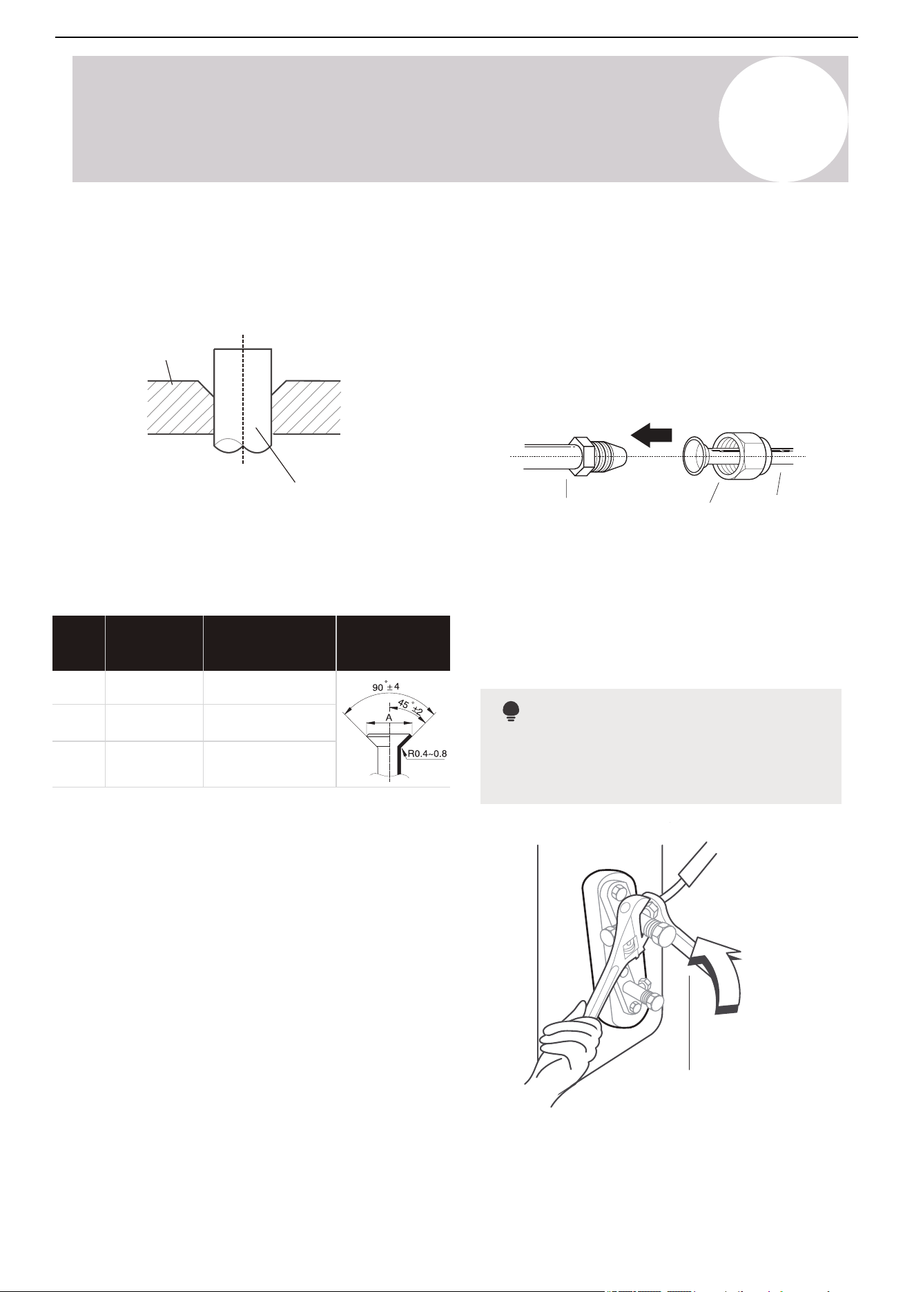
Step 2: Remove Burrs
Burrs can affect the air-tight seal of the refrigerant
piping connection. They must be completely
removed.
Point down
Pipe
Reamer
1. Hold the pipe at a downward angle to prevent
burrs from falling into the pipe.
2. Use a reamer or deburring tool to remove all the
burrs from the cut section of the pipe.
Step 3: Flare Pipe Ends
Proper flaring is essential to achieve an airtight seal.
Flare nut
Copper pipe
1. After removing burrs from the cut pipe, seal the
ends with PVC tape to prevent foreign materials from
entering the pipe.
2. Sheath the pipe with insulating material.
3. Place flare nuts on both ends of the pipe. Make
sure they are facing the correct direction, because it
is not possible to change their direction after flaring.
4. Remove the PVC tape from the ends of the pipe
when ready to perform the flaring work.
Air Conditioner Installation & User Manual
Refrigerant Piping Connection
6
Flare Shape
Tightening
Torque
Pipe
Gauge
Flare Dimension (A)
0.33~0.34 in (8.4~8.7 mm)
0.52~0.53 in (13.2~13.5 mm)
0.64~0.65 in (16.2~16.5 mm)
18-20 N.m
(180-200 kgf.cm)
32-39 N.m
(320-390 kgf.cm)
49-59 N.m
(490-590 kgf.cm)
Ø ¼ in
(6.35 mm)
Ø ⅜ in
(9.52 mm)
Ø ½ in
(12.7 mm)
8. Remove the flaring tool and flare form,
then inspect the end of the pipe for cracks
and flaring.
41
Flare form
Pipe
Step 3: Flare Pipe Ends (Continued)
5. Clamp the flare form on the end of the
pipe. The end of the pipe must extend beyond
the flare form.
6. Place the flaring tool onto the form.
7. Turn the handle of the flaring tool
clockwise until the pipe is fully flared.
Indoor unit tubing
Flare nut
Pipe
Use both a spanner and torque wrench when
connecting or disconnecting pipes to/from the
unit.
Torque wrench
Step 4: Connect Pipes
Connect the copper pipes to the indoor unit first,
then connect it to the outdoor unit. Connect the low-
pressure pipe, then the high-pressure pipe.
1. When connecting the flare nuts, apply a thin coat
of refrigeration oil to the flared ends of the pipes.
2. Align the center of the two pipes intended to be
connected.
3. Tighten the flare nut snugly by hand.
4. Use a wrench to grip the nut on the unit tubing.
5. While firmly gripping the nut, use a torque wrench
to tighten the flare nut according to the torque valves
in the table.
Note
Air Conditioner Installation & User Manual
Refrigerant Piping Connection
6
CAUTION
Ensure to wrap the insulation around the piping. Direct contact with the bare piping may result in
burns or frostbite.
• Make sure the pipe is properly connected. Over tightening may damage the bell mouth, while under
tightening may lead to leakage.
Note
Minimum Bend Radius
• Carefully bend the tubing in the middle
according to the diagram.
• Do not bend the tubing more than 90° or
more than three times.
Use appropriate tool
Min-radius 3.9 inch (99 mm)
Note
Step 4: Connect Pipes (Continued)
CAUTION
Check to make sure that there is no refrigerant
leakage after completing the installation work.
If there is refrigerant leakage, ventilate the area
immediately and evacuate the system. Refer to
the Air Evacuation section of this manual.
6. After connecting the copper pipes to the indoor unit, wrap the power cable, signal cable, and piping
together with binding tape.
7. Thread this pipeline through the wall and connect it to the outdoor unit.
8. Insulate all the piping, including the valves of the outdoor unit.
9. Fix the water receiver (supplied in the accessories box) to the indoor unit using a screw.
10. Open the stop valves of the outdoor unit to start the flow of the refrigerant.
• Do not intertwine the signal cable with other
wires while bundling these items together.
• Do not intertwine or cross the signal cable
with any other wiring.
42
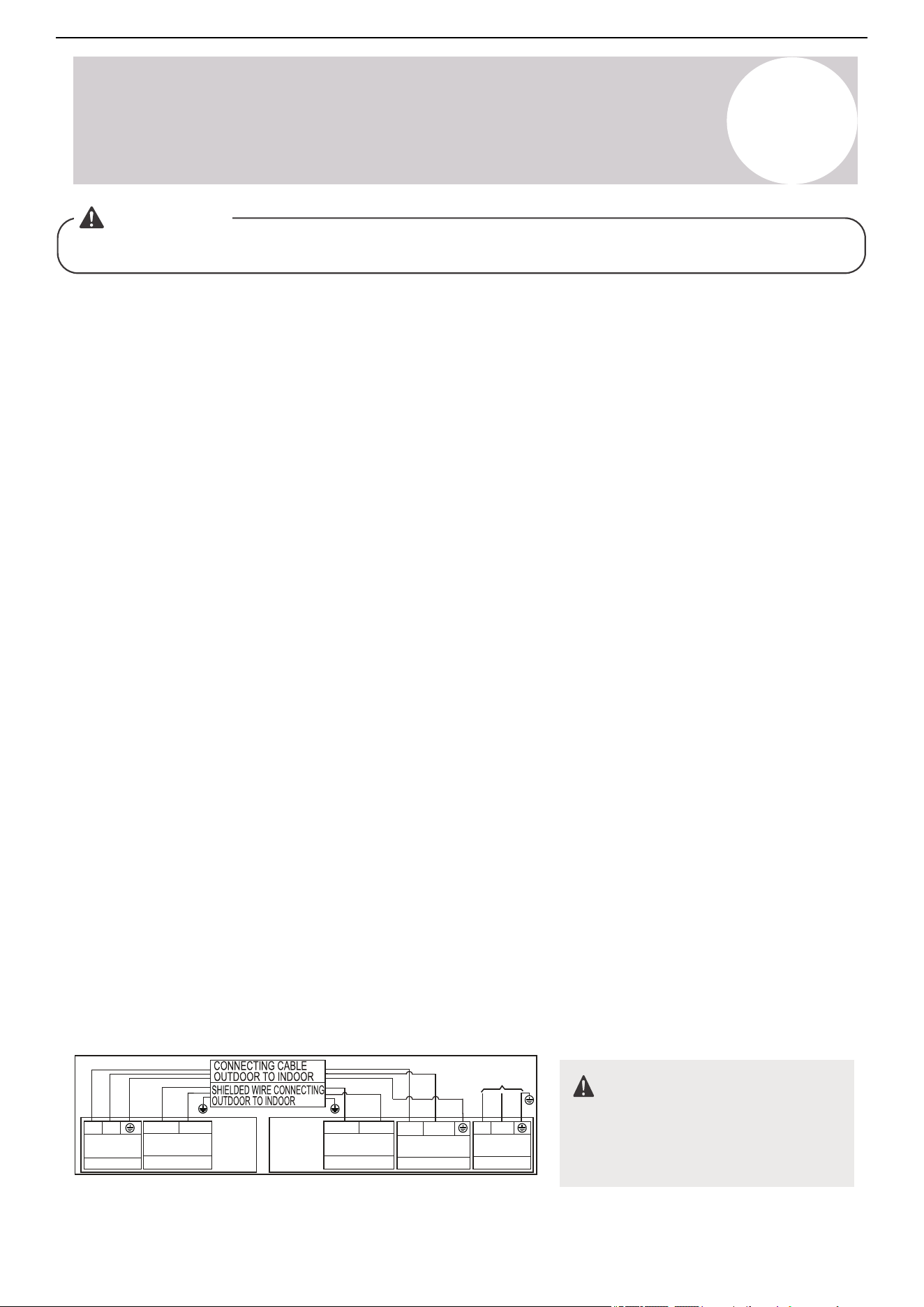
Air Conditioner Installation & User Manual
Wiring Precautions
7
WARNING
Before performing any electrical work, read these warnings.
• All wiring must comply with local and national electrical codes and regulations. A licensed electrician must
install all the wiring.
• All electrical connections must be made according to the electrical connection diagram located on the panels
of the indoor and outdoor units.
• If there is a serious safety issue with the power supply, stop work immediately. Explain the reasoning to the
client and refuse to install the unit until the safety issue is properly resolved.
• The power voltage must be within 90-110% of the rated voltage. Insufficient power supply can cause
malfunction, electrical shock, or fire.
• Installing an external surge suppressor at the outdoor disconnect is recommended.
• If connecting power to fixed wiring, incorporate a switch or circuit breaker that disconnects all poles and has a
contact separation of at least 1/8 of an inch (3 mm). Qualified technicians must use an approved circuit
breaker or switch.
• Only connect the unit to an individual branch circuit. Do not connect another appliance to that outlet.
• Make sure to properly ground the air conditioner.
• Firmly connect every wire. Loose wiring can cause the terminal to overheat, resulting in product malfunction
and possible fire.
• Do not let wires touch or rest against the refrigerant tubing, compressor, or any moving parts.
• If the unit has an auxiliary electric heater, install it at least 3.3 feet (1 m) away from any combustible materials.
• After turning off the power, always wait 10 minutes or more before touching the electrical components in order
to avoid electrical shock.
• Do not cross the electrical wiring with the signal wiring. This may cause distortion, interference, or possibly
damage to circuit boards.
• Do not connect other equipment to the same power circuit.
• Connect the outdoor wires before connecting the indoor wires.
208/230V
Main
INDOOR
UNIT
OUTDOOR
UNIT
Indoor Unit
Power Supply
L1 L2
Nonpolar RS-485
communication
Low voltage
S1 S2
Nonpolar RS-485
communication
Low voltage
S1 S2
Power to
Indoor Unit
L1
L2
208/230V
(1)L1
(2)L2
208/230V
208/230V~60Hz
PE
Power Supply
Power Supply
WARNING
Before performing any electrical or
wiring work, turn off the main power to
the system.
Connection Diagram (36K/48K)
43
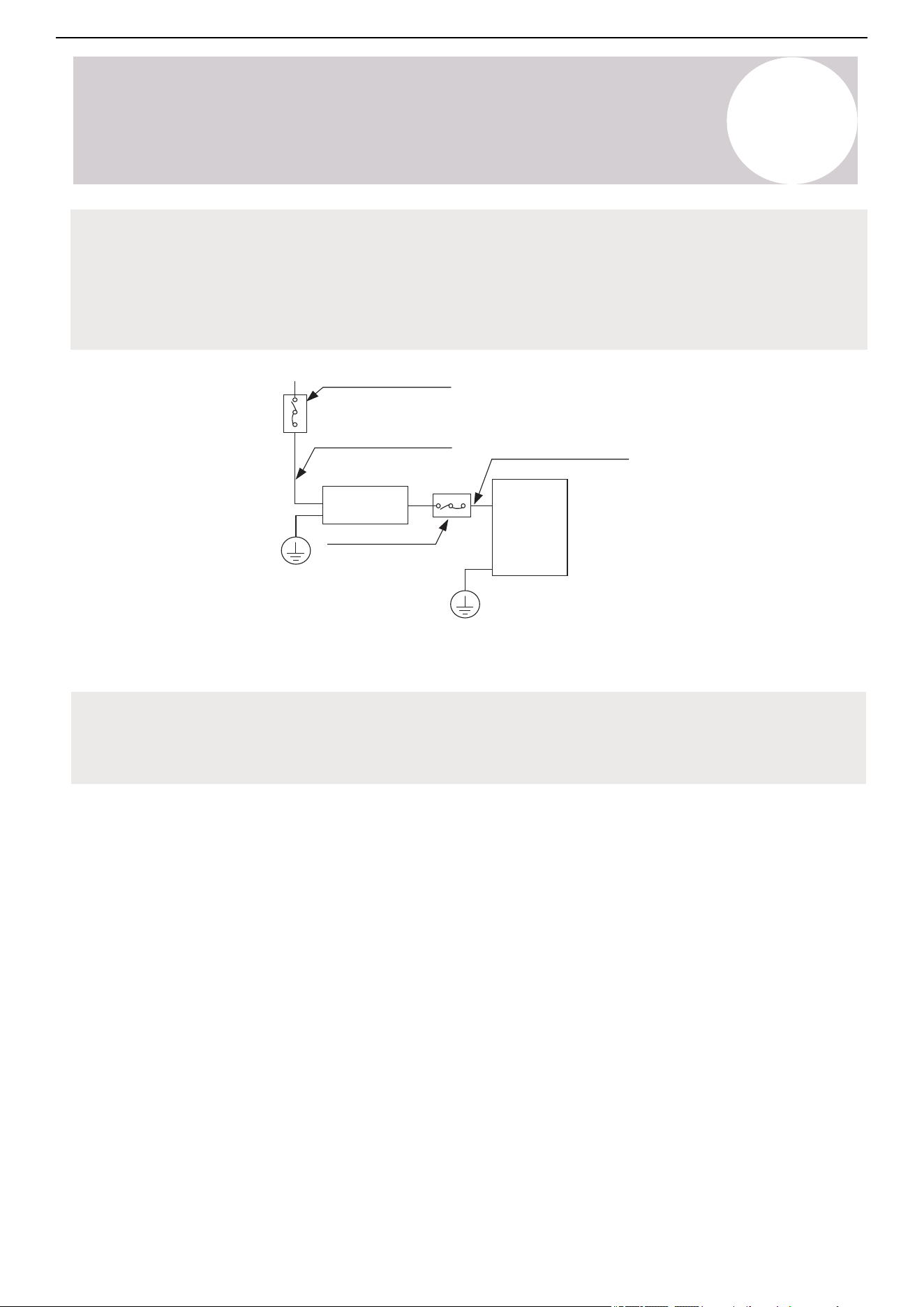
Air Conditioner Installation & User Manual
Wiring Precautions
7
Note for Service Disconnect
When the maximum current of the air conditioner is more than 16A, use a service disconnect or leakage
protection switch with a protective device (purchased separately). When the maximum current of the air
conditioner is less than 16A, equip the power cord of the air conditioner with a plug (purchased separately). In
North America, wire the appliance according to NEC and CEC requirements.
Service disconnect
(purchased separately)
Outdoor unit power wires
Outdoor
unit
Service disconnect
(purchased separately)
Indoor
unit
Indoor & outdoor
connective wires
(purchased separately)
Note: The cographs are for explanation purposes only. The machine may be slightly different. The actual
shape shall prevail.
Select the service disconnect as required by local, regional, and national codes.
44
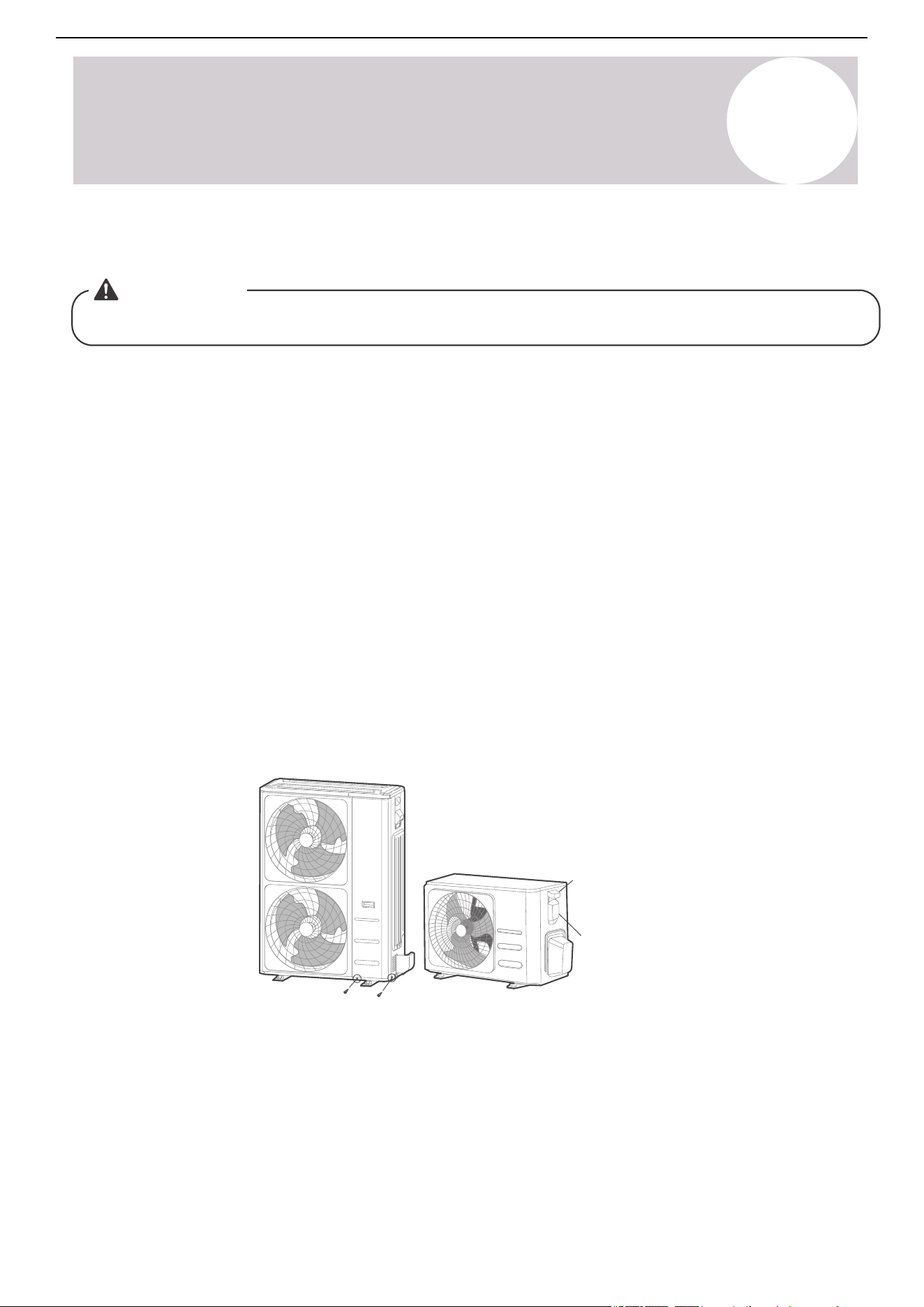
Air Conditioner Installation & User Manual
Wiring Precautions
7
Outdoor Unit Wiring
WARNING
Before performing any electrical or wiring work, turn off the main power to the system.
1. Prepare the cable for connection:
a) Begin by choosing the correct cable size. Choose the cable type according to the local electrical codes and
regulations.
b) The minimum circuit ampacity of the unit determines the size of the power supply cable, signal cable, fuse, and
switch needed. The minimum circuit ampacity is indicated on the nameplate located on the side panel of the unit.
Refer to the nameplate to choose the correct cable, fuse, or switch.
c) Use wire strippers to strip the rubber jacket from both ends of the signal cable to reveal approximately 5.9
inches (150 mm) of wire.
d) Strip the insulation from the ends of the cable.
e) Use a wire crimper to crimp u-lugs on the ends.
Note: When connecting the wires, strictly follow the wiring diagram inside the electrical box cover.
2. Remove the two screws fixed on the front and side panels, then take it down to perform the wire connection
(See the figure of outdoor unit A).
Unscrew the electrical wiring cover and remove it (See the figure of outdoor unit B).
2 screws
Outdoor Unit A Outdoor Unit B
Cover
Screw
3. Connect the u-lugs to the terminals. Match the wire colors/labels with the labels on the terminal block. Firmly
screw the u-lug of each wire to its corresponding terminal.
4. Clamp down the cable with the cable clamp.
5. Insulate unused wires with electrical tape. Keep them away from any electrical or metal parts.
6. Reinstall the cover of the electrical control box.
45
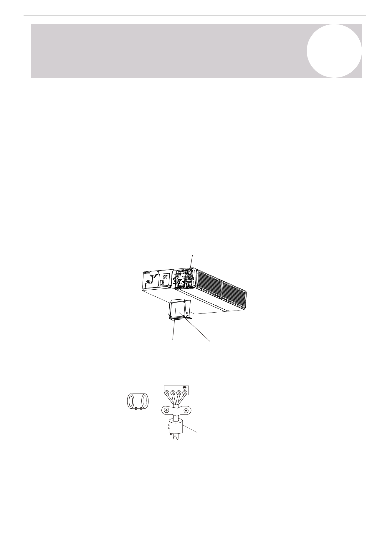
Air Conditioner Installation & User Manual
Wiring Precautions
7
Indoor Unit Wiring
1. Prepare the cable for connection:
a) Use wire strippers to strip the rubber jacket from both ends of the signal cable to reveal about 5.9 inches (150
mm) of the wire.
b) Strip the insulation from the ends of the wires.
c) Use a wire crimper to crimp the u-lugs to the ends of the wires.
2. Remove the cover of the electric control box on the indoor unit.
3. Connect the u-lugs to the terminals.
Match the wire colors/labels with the labels on the terminal block. Firmly screw the u-lug of each wire to its
corresponding terminal. Refer to the serial number and wiring diagram located on the cover of the electric control
box.
Connective
wiring diagram
Wiring
diagram
Control box
Magnetic ring (if supplied and packed with the
accessories)
1 2 3
Pass the belt through the
hole of the Magnetic ring to
fix it on the cable
4. Clamp down the cable with the cable clamp. The cable must not be loose or pull on the u-kugs.
46
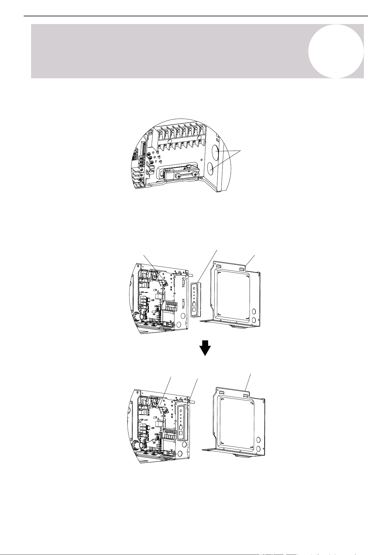
Air Conditioner Installation & User Manual
Wiring Precautions
7
5. Pass the wire through the knock-down hole on the electric control box.
Knock-down
hole
6. Reattach the electric box cover.
7. If the indoor unit is equipped with a display box, it needs to be installed in the electric control box.
Electric control box
Electric control box
Display box
Display box
Electric control box cover
Electric control box cover
47
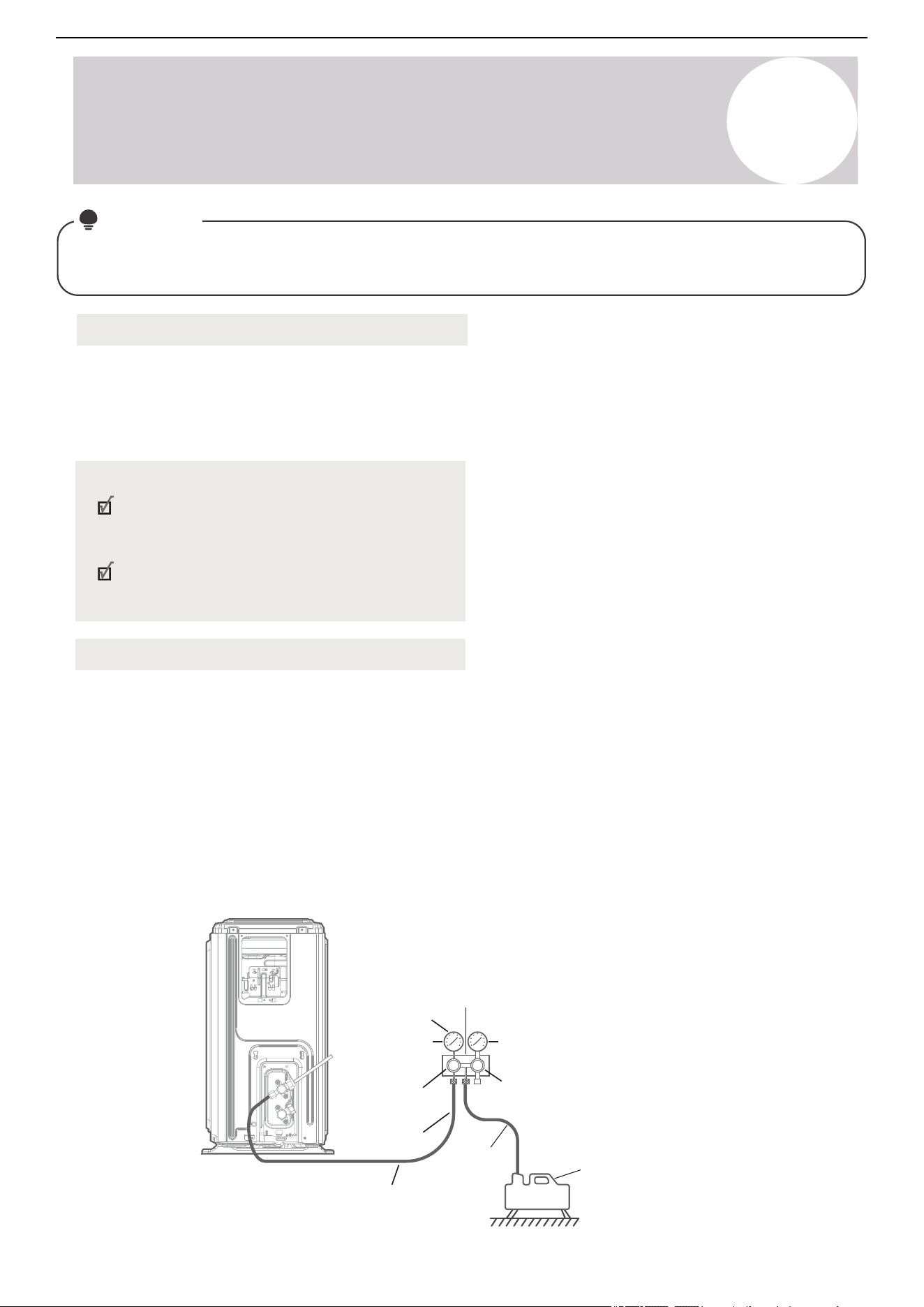
Air Conditioner Installation & User Manual
Air Evacuation
8
Notice
When opening the valve stems, turn the hexagonal wrench until it hits against the stopper. Do not try to force
the valve to open further.
Preparations & Precautions
Air and foreign matter in the refrigerant circuit can lead to abnormal rises in pressure, which can damage the air
conditioner, reduce its efficiency, and cause injury. Use a vacuum pump and manifold gauge to evacuate the
refrigerant circuit, removing any non-condensable gas and moisture from the system. Perform the evacuation
after the initial installation and when relocating the unit.
Before Performing the Evacuation
Check to make sure the connective pipes
between the indoor and outdoor units are
connected properly.
Check to make sure all wiring is connected
properly.
Evacuation Instructions
1. Connect the charge hose of the manifold gauge to the service port on the outdoor unit's low-pressure valve.
2. Connect another charge hose from the manifold gauge to the vacuum pump.
3. Open the low-pressure side of the manifold gauge. Keep the high-pressure side closed.
4. Turn on the vacuum pump to evacuate the system.
5. Run the vacuum for at least 15 minutes or until the compound meter reads -76cmHG (-10
5
Pa).
Outdoor
Unit
Manifold
Gauge
-76cmHg
Compound
gauge
Low-pressure
valve
Pressure hose
or
Charge hose
Low-pressure
valve
Pressure gauge
High-pressure
valve
Charge
hose
Vacuum pump
48
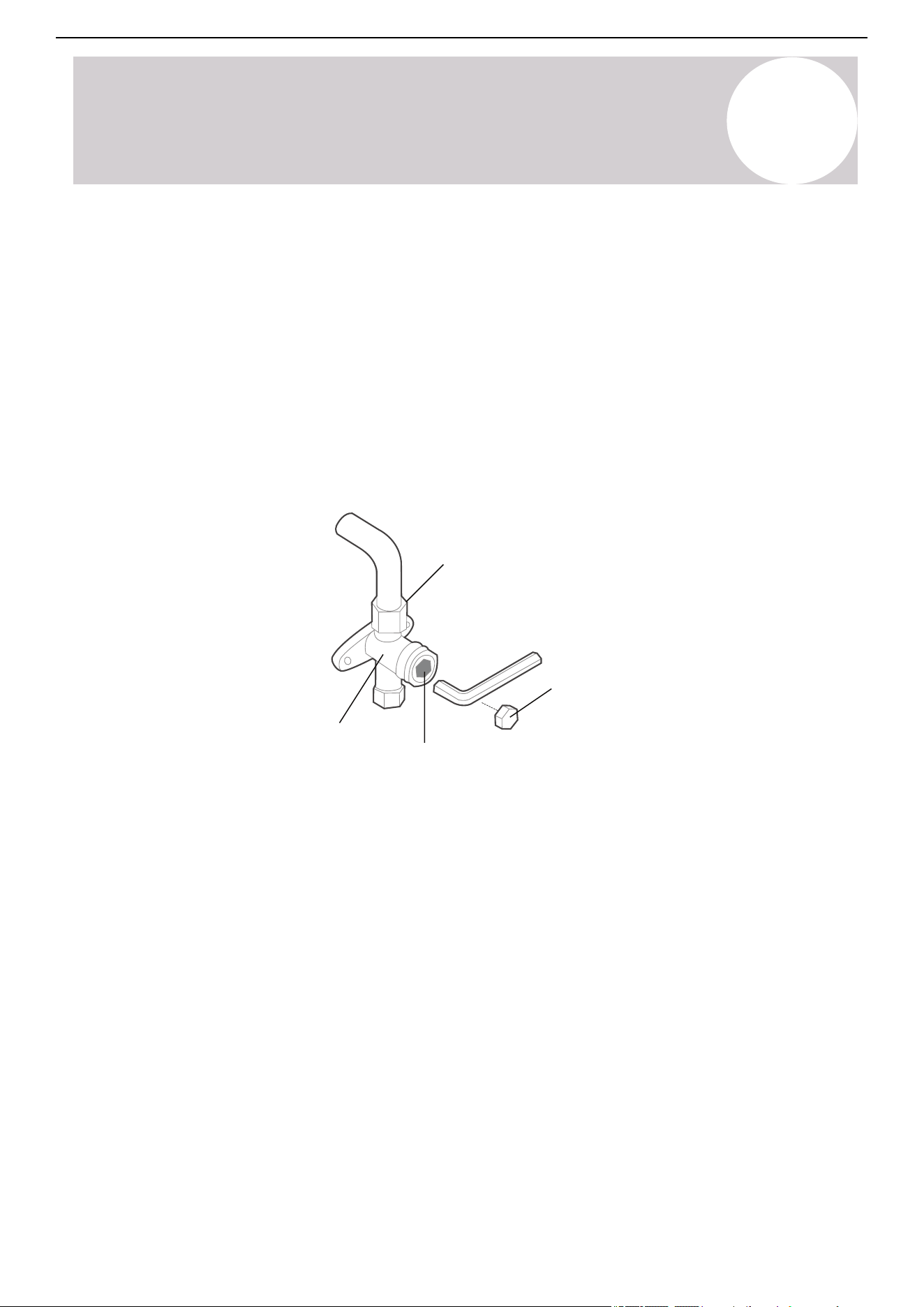
Air Conditioner Installation & User Manual
Air Evacuation
8
49
6. Close the low-side pressure of the manifold gauge, then turn off the vacuum pump.
7. Wait for 5 minutes, then confirm that there has been no change in system pressure.
8. If there is a change in system pressure, refer to the information on how to check for leaks. If there is no change
in system pressure, unscrew the cap from the packed valve (high-pressure valve),
9. Insert a hexagonal wrench into the packed valve (high-pressure valve) and open the valve by turning the
wrench 1/4 counterclockwise. Listen for gas exiting the system, then close the valve after 5 seconds.
10. Watch the pressure gauge for 1 minute to make sure that there is no change in pressure. The pressure gauge
should read slightly higher than the atmospheric pressure.
11. Remove the charge hose from the service port.
Flare nut
Valve body
Valve stem
Cap
12. Use a hexagonal wrench to fully open both the high-pressure and low-pressure valves.
13. Tighten the caps on all three valves by hand (service port, high pressure, and low pressure). Use a torque
wrench to tighten it further.

Air Conditioner Installation & User Manual
CAUTION
Do not mix different types of refrigerant.
Some systems require additional charging depending on the pipe lengths. In North America, the standard pipe
length is 25 feet (7.5 m). Charge the refrigerant from the service port on the outdoor unit's low-pressure valve.
Calculate the additional refrigerant to be charged using the following formula (the refrigerant quantity added in
the following table is a reference value and can be adjusted according to the actual situation):
Note on Adding Refrigerant
9
Liquid Side Diameter
Refrigerant
R-454B
Ø1/4 in (Ø6.35 mm)
Ø3/8 in (Ø9.52 mm)
(Pipe length - standard length) x 15g/m
(Pipe length - standard length) x 0.16oz/ft
(Pipe length - standard length) x 30g/m
(Pipe length - standard length) x 0.32oz/ft
50

Air Conditioner Installation & User Manual
CAUTION
Failure to perform the test run may result in unit damage, property damage, or personal injury.
Before Test Run
Perform the test run after the entire system has been completely installed. Confirm the following points
before performing the test:
a) The indoor and outdoor units are properly installed.
b) The piping and wiring are properly connected.
c) There are no obstacles near the inlet and outlet of the unit that might cause poor performance or product
malfunction.
d) The refrigeration system does not leak.
e) The drainage system is unimpeded and draining to a safe location.
f) The heating insulation is properly installed.
g) The grounding wires are properly connected.
h) The length of the piping and additional refrigerant capacity have been recorded.
i) The power voltage is the correct voltage for the air conditioner.
Test Run
10
51

Test Run Instructions
Test Run
Air Conditioner Installation & User Manual
1. Open both the liquid and gas stop valves.
2. Turn on the main power switch and allow the unit to warm up.
3. Set the air conditioner to Cool mode.
4. For the indoor unit:
a) Ensure that the remote control and its buttons operate properly.
b) Ensure that the louvers move properly and can be changed using the remote control.
c) Double check to see if the room temperature is being registered correctly.
d) Ensure that the indicators on the remote control and display panel for the indoor unit operate properly.
e) Ensure that the manual buttons on the indoor unit operate properly.
f) Confirm that the drainage system is unimpeded and draining smoothly.
g) Ensure that there is no vibration or abnormal noise during operation.
5. For the outdoor unit:
a) Check to see if the refrigeration system is leaking.
b) Make sure there is no vibration or abnormal noise during operation.
c) Ensure that the wind, noise, and water generated by the unit does not disturb neighbors or pose a safety
hazard.
6. Drainage Test
a) Ensure that the drain pipe flows smoothly. New buildings should perform this test before finishing the ceiling.
b) Remove the test cover. Add 67.6 oz (2,000 ml) of water to the tank through the attached tube.
c) Turn on the main power switch and run the air conditioner in Cool mode.
d) Listen to the sound of the drain pump to check if it makes any unusual noises.
e) Confirm the water is discharged. It may take up to 1 minute before the unit begins to drain, depending on the
drain pipe.
f) Make sure that there are no leaks in any of the piping.
g) Stop the air conditioner. Turn off the main power switch and reinstall the test cover.
Note: If the unit malfunctions or does not operate according to expectations, refer to the Troubleshooting
section in this manual before calling customer service.
10
52

Commission
Air Conditioner Installation & User Manual
11
The indoor ducted units can be programmed for different static pressure or real-time constant airflows. Use the
following steps to set the static pressure or real-time constant airflow:
When Using the 120L Wired Controller
To set static pressure airflow:
The factory default setting is SP1. The external static pressure can be manually changed to the fan curves 1, 2,
3, 4, 5, 6, 7, 8.
a. Press and hold the On/Off and Fan buttons for approximately 7 seconds.
b. Press the up or down buttons to scroll through the menu and select "8".
c. Press and hold the On/Off button for approximately 2 seconds. Press the up or down buttons to scroll through
the menu, then select "1-8".
d. Press the check mark button and the display board displays "CS".
e. Press and hold the On/Off and Fan buttons for approximately 7 seconds, then exit test mode.
To set real-time constant airflow:
Use the Automatic Airflow Adjustment function "AF" to realize real-time constant airflows.
a. Press and hold the On/Off and Fan buttons for approximately 7 seconds.
b. Press the up or down buttons to scroll through the menu and select "8".
c. Press and hold the On/Off button for approximately 2 seconds. Press the up or down buttons to scroll through
the menu, then select "AF".
d. Press the check mark button and the display board displays "CS".
e. Press and hold the On/Off and Fan buttons for approximately 7 seconds, then exit test mode.
Notes:
• Before commissioning, check the power connection of the machine, turn on the power, and ensure the
machine is not operating.
• If there is no change after airflow adjustment, perform the setting again.
• Low static pressure series 9K, 12K, and 18K models, the SP options can only be "1-4".
53

When Using the 120N Wired Controller
To set static pressure airflow:
The factory default setting is SP1. The external static pressure can be manually changed to the fan curves 1,
2, 3, 4, 5, 6, 7, 8.
a. Press and hold the Copy button for approximately 3 seconds. The lower right corner shows "P:00". Press the
check mark button.
b. Press the up button to scroll through the menu. The lower right corner shows "SP". Press the check mark
button.
c. Press the up and down buttons to scroll through the menu and select "1-8". Then, press the check mark
button.
d. Press the back button to exit the test mode.
To set real-time constant airflow:
Use the Automatic Airflow Adjustment function "AF" to realize real-time constant airflows.
a. Press and hold the Copy button for approximately 3 seconds. The lower right corner shows "P:00". Press the
check mark button.
b. Press the up button to scroll through the menu. The lower right corner shows "AF". Press the check mark
button.
c. Press the back button to exit the test mode.
Commission
Air Conditioner Installation & User Manual
11
Notes:
• T1, T2, T2b, T3, T4 are sub-menus for thermistors. Do not select to set the external static pressure.
• Before commissioning, check the power connection of the machine, turn on the power, and ensure the
machine is not operating.
• If there is no change after airflow adjustment, perform the setting again.
• Use the wired remote controller to set the static pressure or automatic airflow.
• Low static pressure series 6K, 9K, 12K, and 18K models, SP options can only be "1-4".
54

Air Conditioner Installation & User Manual
Instructions for unpacking and packing the unit:
Unpacking:
Indoor Unit:
1. Cut the packing belt.
2. Unpack the package.
3. Take out the packing cushion and support.
4. Remove the packing film.
5. Take out the accessories.
6. Lift the machine out and lay it flat.
Outdoor Unit:
1. Cut the packing belt.
2. Take the unit out of the package.
3. Remove the foam from the unit.
4. Remove the packing film from the unit.
Packing:
Indoor Unit:
1. Put the indoor unit into the packing film.
2. Put the accessories in.
3. Place the packing cushion and support.
4. Put the indoor unit into the package.
5. Close the package and seal it.
6. Use the packing belt if necessary.
Outdoor Unit:
1. Put the outdoor unit into the packing film.
2. Put the bottom foam into the box.
3. Put the outdoor unit into the package, then put the upper packaging foam on the unit.
4. Close the package and seal it.
5. Use the packing belt if necessary.
Note: Keep all the packaging items in case they're needed in the future.
Unpacking & Packing
12
55
Air Conditioner Installation & User Manual
13
Care & Maintenance
CAUTION
Clean the Indoor & Outdoors Units
• Always turn off the AC system and disconnect its power supply before cleaning or maintenance.
• Only use a soft, dry cloth to wipe the unit clean. Use a cloth soaked in warm water to wipe it clean if the unit
is especially dirty.
• Do not use chemicals or chemically treated cloths to clean the unit.
• Do not use benzene, paint thinner, polishing powder, or other solvents to clean the unit. They can cause the
plastic surface to crack or deform.
• Do not use water hotter than 104°F (40°C) to clean the front panel. This can cause the panel to deform or
become discolored.
• Before changing the filter or cleaning, turn off the unit and disconnect its power supply. A certified technician
must perform the removal and maintenance of the indoor unit.
• When removing the filter, do not touch metal parts in the unit. The sharp metal edges can cut you.
• Do not use water to clean the inside of the indoor unit. This can destroy insulation and cause electrical shock.
• Do not expose the filter to direct sunlight when drying. This can shrink the filter.
• An authorized dealer or licensed service provider must perform the maintenance and cleaning of the outdoor
unit.
• An authorized dealer or licensed service provider must perform any repairs to the unit.
• A professional must clean and remove the filter.
Maintenance –
Long Periods of Non-Use
Maintenance –
Pre-Season Inspection
After long periods of non-use, or before
periods of frequent use, do the following:
Maintain the AC
If the air conditioner won't be used for an
extended period of time.
Turn off the unit and
disconnect the power
Turn on the Fan function until the
unit dries out completely
Make sure nothing is blocking the air inlets
and outlets
Check for damaged wires
Check for leaks
56
Air Conditioner Installation & User Manual
Unit does not turn on when
pressing the On/Off button
Unit changes from
Cooling/Heating mode
to Fan mode
Indoor unit emits white
mist
Indoor and outdoor units
emit white mist
Indoor unit makes noises
Indoor and outdoor units
make noises
The unit has a 3-minute protection feature that prevents the unit from overloading. The
unit cannot be restarted within 3 minutes of being turned off.
Cooling and Heating mode: If the operation light and PRE-DEF (pre-heating/defrost)
indicators are lit up, the outdoor temperature is too cold, activating the unit's anti-cold
wind feature in order to defrost the unit.
In Cooling-only mode: If the Fan-Only indicator is lit up, the outdoor temperature is
too cold, activating the unit's anti-freeze protection in order to defrost the unit.
The unit may change its settings to prevent frost from forming on the unit. Once
the temperature increases, the unit will start operating in the previously selected
mode again.
The set temperature has been reached, at which point the unit turns off the
compressor. The unit will continue operating when the temperature fluctuates again.
In humid regions, a large temperature difference between the room's air and the
conditioned air can cause white mist.
When the unit restarts in Heating mode after defrosting, white mist may be emitted
due to moisture generated from the defrosting process.
A rushing air sound may occur when the louver resets its position.
A squeaking sound is heard when the system is off or in Cooling mode. The noise is
also heard when the drain pump (optional) is in operation.
A squeaking sound may occur after running the unit in Heating mode, due to
expansion and contraction of the unit's plastic parts.
Low hissing sound during operation: This is normal and caused by refrigerant
gas flowing through both the indoor and outdoor units.
Low hissing sound when the system starts, stops running, or defrosting: This noise is
normal and caused by the refrigerant gas stopping or changing direction.
Squeaking sound: Normal expansion and contraction of plastic and metal parts
caused by temperature changes during operation can cause squeaking noises.
Issue
Possible Causes
The following issues are not malfunctions and will not require repairs in most situations:
Common Issues
CAUTION
If any of the following conditions occur, turn off the unit immediately:
• The power cord is damaged or abnormally warm.
• A burning odor is present.
• The unit is emitting loud or abnormal sounds.
• A power fuse blows or the circuit breaker frequently trips.
• Water or other objects fall into or out of the unit.
Do not attempt to fix these problems by yourself. Contact an authorized service provider immediately.
T
Troubleshooting
57
Air Conditioner Installation & User Manual
Problem
Possible Causes
Solution
Poor Cooling
Performance
The temperature setting may be higher
than the ambient room temperature.
Heat exchanger on the indoor or
outdoor unit is dirty.
Air filter is dirty.
Air inlet or outlet of either unit is
blocked.
Doors and windows are open.
Excessive heat is generated by sunlight.
Too many sources of heat in the room
(people, computers, electronics, etc.).
Low refrigerant due to leak or long-
term use.
Lower the temperature setting.
Clean the affected heat exchanger.
Remove the filter and clean it according
to the instructions in this manual.
Turn the unit off, remove the obstruction, and
turn it back on.
Make sure that all doors and windows are
closed while operating the unit.
Close windows and curtains during periods
of high heat or bright sunshine.
Reduce the amount of heat sources.
Check for leaks. Reseal if necessary and top
off the refrigerant.
When trouble occurs, check the following points before contacting a repair company:
Note: If the problem persists, contact a local dealer or the nearest customer service center. Provide them with
a detailed description of the unit malfunction and model number.
Outdoor unit
makes noises
Dust is emitting from
either the indoor or
outdoor unit
Unit emitting bad odor
Fan of the outdoor
unit does not operate
The outdoor unit will make different sounds based on its current operating mode.
The unit may accumulate dust during extended periods of non-use, which will be emitted
when the unit is turned on. This can be mitigated by covering the unit during long periods
of inactivity.
The unit may absorb odors from the environment, which will be emitted during
operations. Examples are furniture, cooking, cigarettes, etc.
The unit's filters have become moldy and need to be cleaned.
During operation, the fan speed is controlled to optimize product operation.
Issue
Possible Causes
T
Troubleshooting
58
Air Conditioner Installation & User Manual
Poor heating
performance
Unit starts and stops
frequently
Unit is not working
Outdoor temperature is
extremely low.
Cold air is entering through
doors and windows.
Low refrigerant due to leak
or long-term use.
Use an auxiliary heating device.
Make sure that all doors and windows are
closed during use.
Check for leaks. Reseal if necessary and top
off refrigerant.
There's too much or little
refrigerant in the system.
Incompressible gas or moisture
has entered the system.
System circuit is blocked.
Compressor is broken.
Voltage is too high or low.
Check for leaks and recharge the system
with refrigerant.
Evacuate and recharge the system with refrigerant.
Determine which circuit is blocked and replace
the malfunctioning piece of equipment.
Replace the compressor.
Install a manostat to regulate the voltage.
Power failure.
Power is turned off.
Fuse is burned out.
Remote control batteries
are dead.
The unit's 3-minute protection
has been activated.
The unit's timer is activated.
Wait for the power to be restored.
Turn on the power.
Replace the fuse.
Replace the batteries.
Wait 3 minutes after restarting the unit.
Turn the timer off.
Problem
Possible Causes
Solution
T
Troubleshooting
The unit may stop operation or continue to run safely. If the indicator lamps continue
to flash or error codes appear, wait about 10 minutes. The problem may resolve
itself.
If not, disconnect the power. Then, connect the power again and turn the unit on.
Indicator lamps
continue to flash
Error codes appear and
begin with the letters as
the following in the
window display of the
indoor unit:
• E (x), P (x), F (x)
• EH (xx), EL (xx), EC
(xx)
• PH (xx), PL (xx), PC
(xx)
Note: If the problem continues after performing the checks and diagnostics above,
turn off the unit immediately and contact an authorized service center.
The design and specifications are subject to change without prior notice for product
improvements. Consult with the sales agency or manufacturer for details. Any
updates to the manual will be uploaded to the service website, check for the latest
version.
59

The design and specifications of this product are subject to change without prior notice
as development continues. Consult with the sales agency or manufacturer for details.
Refer to the equipment nameplate for all other applicable specifications.
Copyright © Parker Davis HVAC International, LLC. All rights reserved.
is a registered trademark of Parker Davis HVAC International, LLC.
Parker Davis HVAC International
7290 NW 77 Court, Miami, FL 33166 - USA
Tel
: (305) 513-4488
Fax
: (305) 513-4499
E-mail
Website: www.pdhvac.com
Pioneer product line, parts, and supplies are
available online for convenient ordering at:
www.highseer.com
www.pioneerminisplit.com
Scan the below code to visit our support page
where you can find more installation materials:
5060