PLACE THESE INSTRUCTIONS ADJACENT TO HEATER AND NOTIFY OWNER TO KEEP FOR FUTURE REFERENCE.
KEEP THIS MANUAL IN THE POCKET ON HEATER FOR FUTURE REFERENCE WHENEVER MAINTENANCE ADJUSTMENT OR SERVICE IS
REQUIRED.
PRINTED 0525 100338313_2000594665A
Instruction Manual
RESIDENTIAL GAS WATER HEATERS
LOW LEAD
CONTENT
WARNING: If the information in these
instructions is not followed exactly, a fire
or explosion may result causing property
damage, personal injury or death.
Do not store or use gasoline or other
flammable vapors and liquids in the
vicinity of this or any other appliance.
WHAT TO DO IF YOU SMELL GAS:
Do not try to light any appliance.
Do not touch any electrical switch; do
not use any phone in your building.
Immediately call your gas supplier
from a neighbor’s phone. Follow the
gas supplier’s instructions.
If you cannot reach your gas supplier,
call the fire department.
Installation and service must be
performed by a qualified installer,
service agency or the gas supplier.
•
•
•
•
Thank you for buying this energy efficient water heater. We
appreciate your confidence in our products.
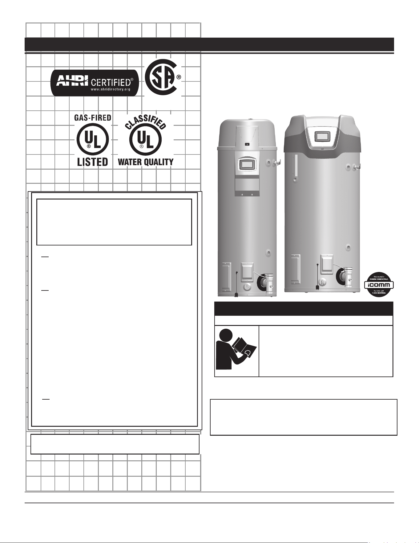
POWER VENT/POWER DIRECT VENT GAS MODELS
WITH DIRECT SPARK IGNITION
MODELS 50/75 GALLON SERIES 400/401
INSTALLATION - OPERATION - SERVICE - MAINTENANCE
Failure to follow these instrucons and safety
messages could result in death or serious injury.
Read and understand this instrucon manual and the
safety messages herein before installing, operang or
servicing this water heater.
This manual must remain with the water heater.
⚠
WARNING
Safety Hazard
For Your Safety
AN ODORANT IS ADDED TO THE GAS USED
BY THIS WATER HEATER.

2
CONTENTS
APPROVALS .............................................................................................3
GENERAL SAFETY INFORMATION .......................................................... 3
Precautions .......................................................................................... 3
Limiting the Risk of Scalding ................................................................3
Grounding Instructions ........................................................................3
Hydrogen Gas Flammable ....................................................................3
Important Definitions ..........................................................................4
Hazard Messages .................................................................................4
INTRODUCTION ......................................................................................8
Abbreviations Used..............................................................................8
Qualifications ....................................................................................... 8
Preparing For The Installation .............................................................8
FEATURES AND COMPONENTS ............................................................10
Controls And Switches .......................................................................12
Other Features ...................................................................................13
INSTALLATION CONSIDERATIONS .......................................................14
Locating The Water Heater ................................................................ 15
Insulation Blankets ............................................................................16
Combustion Air And Ventilation ........................................................17
Unconfined Space .............................................................................. 17
Unusually Tight Construction ............................................................17
Confined Space .................................................................................. 17
Direct Vent Appliances.......................................................................17
Exhaust Fans ......................................................................................17
Louvers and Grilles ............................................................................17
Fresh Air Openings For Confined Spaces ...........................................17
INSTALLATION REQUIREMENTS ..........................................................20
Chemical Vapor Corrosion .................................................................20
Water Piping ......................................................................................20
Power Supply ..................................................................................... 20
Dedicated Power Wiring and Breakers ..............................................20
Power Fluctuations and Electrical Noise ............................................20
Thermostatic Point-of-Use Mixing Valves ..........................................21
Gas Supply Systems ...........................................................................21
Gas Pressure Requirements ............................................................... 21
Supply Gas Regulator ......................................................................... 21
Space Heating And Potable Water System ........................................22
Closed Water Systems .......................................................................22
Thermal Expansion ............................................................................22
Temperature-Pressure Relief Valve .................................................... 23
T&P Valve Discharge Pipe Requirements: .......................................... 23
Condensate Piping .............................................................................24
Condensate Ph Level .........................................................................24
High Altitude Installations .................................................................25
Massachusetts Installation Requirements .........................................26
VENTING INSTALLATION ......................................................................27
Vent Installation Considerations ........................................................ 27
Vent/Intake Material..........................................................................27
Polypropylene Installations ...............................................................28
Vent Pipe Termination .......................................................................28
Planning The Vent System .................................................................28
Installation Of Horizontal Through The Wall Vent System .................29
Vent Terminal Installation, Sidewall ................................................... 29
Direct Vent Terminal Installation .......................................................29
Direct Vent Air Intake Moisture Protection .......................................30
Installation Sequence ........................................................................30
Vertical Vent Terminal Installation .....................................................30
Flat Roof Installation .......................................................................... 30
Sidewall Termination direct vent Clearances ..................................... 32
Sidewall Termination Clearances Other Than Direct Vent .................33
Direct Vent Diagram ..........................................................................34
Low Profile Termination Installation .................................................. 35
WATER HEATER INSTALLATION ............................................................ 36
Condensate Drain Installation ...........................................................36
Gas Piping ..........................................................................................37
Sediment Traps ..................................................................................37
Electrical Wiring .................................................................................37
Dedicated Power Wiring and Breakers ..............................................37
Leak Detection Module .....................................................................38
START UP ...............................................................................................39
Prior to Start up .................................................................................39
Gas Calibration ..................................................................................40
Lighting Instructions ..........................................................................41
TEMPERATURE REGULATION ...............................................................42
Limiting the Risk of Scalding ..............................................................42
High Temperature Limit Control ........................................................42
Thermostat Control ...........................................................................42
High Temperature Applications .........................................................43
CONTROL SYSTEM OPERATION ...........................................................44
Limiting the Risk of Scalding ..............................................................44
Wi-Fi ..................................................................................................44
Lockout Function ...............................................................................44
Control System Overview ..................................................................44
Control System Navigation.................................................................44
User Settings & Control System Menus .............................................46
MAINTENANCE .....................................................................................57
Venting System Maintenance ............................................................57
Draining and Flushing ........................................................................57
Lime Scale Removal ...........................................................................58
Burner Inspection and Maintenance .................................................58
Burner Flame Inspection ...................................................................58
Anode Rod Maintenance ...................................................................59
Temperature-Pressure Relief Valve Test ............................................59
Service ...............................................................................................60
TROUBLESHOOTING ............................................................................. 61
Installation Checklist .......................................................................... 61
Sequence Of Operation .....................................................................61
Start Up Conditions ...........................................................................63
Operational Conditions ......................................................................63
Operational Problems ........................................................................ 63
Replacement Parts ....... ......................................................................64
Fault And Alert Conditions .................................................................64
Checking for Leaks .............................................................................77
Water Leak Detection ........................................................................77
DIAGRAMS ............................................................................................78
Wiring Diagram .................................................................................. 79
Residential Gas Water Heaters • 3
APPROVALS
LOW LEAD
CONTENT
GENERAL SAFETY INFORMATION
PRECAUTIONS
DO NOT USE THIS WATER HEATER IF ANY PART HAS BEEN EXPOSED TO
FLOODING OR WATER DAMAGE
. Immediately call a qualified service agency
to inspect the water heater and to make a determination on what steps
should be taken next.
If the unit is exposed to the following, do not operate heater until all
corrective steps have been made by a qualified service agency.
1. External fire.
2. Damage.
3. Firing without water.
LIMITING THE RISK OF SCALDING
For a variety of reasons, water heaters can produce water that is much
hotter than its temperature setting. Take precautions to prevent this higher
temperature water from reaching the water fixtures.
The temperature of the water in the water
heater can exceed the thermostat se�ng and
be hot enough to cause burns.
To reduce the risk of unusually hot water
reaching the fixtures in the house, install point
of use thermosta�c mixing valves at each point
of use.
⚠
WARNING
Burn Hazard
According to a national standard ,
Performance Requirements for Water
Temperature Limiting Devices (ASSE 1070)
and many local plumbing codes,
the water heater’s gas control valve should not be used as the sole means
to regulate water temperature and avoid scalds.
A properly adjusted thermostatic mixing valve at each point of use allows
you to set the tank temperature to a higher setting without increasing
risk of scalds. A higher temperature setting allows the tank to provide
much more hot water and can help provide proper water temperatures
for appliances such as dishwashers and washing machines.
GROUNDING INSTRUCTIONS
This water heater must be grounded in accordance with the
National
Electrical Code
and/or local codes. These codes must be followed in all
cases. Failure to ground this water heater properly may also cause erratic
control system operation.
This water heater must be connected to a grounded metal, permanent
wiring system; or an equipment grounding conductor must be run with
the circuit conductors and connected to the equipment grounding terminal
or lead on the water heater.
HYDROGEN GAS FLAMMABLE
Flammable hydrogen gases can form in water pipes.
The hydrogen can explode if it is exposed to flame and
can cause severe injury or death.
Keep all igni�on sources away from faucet when
turning on hot water.
⚠
WARNING
Explosion Hazard
Hydrogen gas can be produced in a hot water system served by this water
heater that has not been used for a long period of time (generally two
weeks or more). Hydrogen gas is extremely flammable. To reduce the risk
of injury under these conditions, it is recommended that a hot water faucet
served by this water heater be opened for several minutes before using
any electrical appliance connected to the hot water system. If hydrogen
is present there will probably be an unusual sound such as air escaping
through the pipe as the water begins to flow. There should be no smoking
or open flame near the faucet at the time it is open.
Verify that the power to the water heater is turned off before performing any service procedures. The Enable/Disable switch on front
panel disables the gas valve. Electrical supply must be turned off at circuit breaker serving water heater.
4 • Residential Gas Water Heaters
General Safety Information
IMPORTANT DEFINITIONS
Qualified Installer: A qualified installer must have ability equivalent to a licensed tradesman in the fields of plumbing, air supply, venting and gas supply,
including a thorough understanding of the requirements of the
National Fuel Gas Code, ANSI Z223.1/NFPA 54
as it relates to the installation of gas fired
water heaters. The qualified installer must also be familiar with the design features and use of flammable vapor ignition resistant water heaters and
have a thorough understanding of this Installation and Operating manual.
Service Agency: A service agency also must have ability equivalent to a licensed tradesman in the fields of plumbing, air supply, venting and gas supply,
including a thorough understanding of the requirements of the
National Fuel Gas Code”, ANSI Z223.1/NFPA 54
as it relates to the installation of gas fired
water heaters. The service agency must also have a thorough understanding of this Installation and Operating manual, and be able to perform repairs
strictly in accordance with the service guidelines provided by the manufacturer.
Gas Supplier: The Natural Gas or Propane Utility or service who supplies gas for utilization by the gas burning appliances within this application. The
gas supplier typically has responsibility for the inspection and code approval of gas piping up to and including the Natural Gas meter or Propane storage
tank of a building. Many gas suppliers also offer service and inspection of appliances within the building.
HAZARD MESSAGES
Your safety and the safety of others is extremely important in the
installation, use and servicing of this water heater. Many safety-related
messages and instructions have been provided in this manual and on your
own water heater to warn you and others of a potential injury hazard. Read
and obey all safety messages and instructions throughout this manual. It
is very important that the meaning of each safety message is understood
by you and others who install, use or service this water heater.
Many safety-related messages and instructions have been provided in
this manual and on your own water heater to warn you and others of a
potential injury hazard. Read and obey all safety messages and instructions
throughout this manual. It is very important that the meaning of each
safety message is understood by you and others who install, use, or service
this water heater.
This is the safety alert symbol. It is used
to alert you to potenal personal injury
hazards. Obey all safety messages that
follow this symbol to avoid possible
injury or death. Keep this manual near
the water heater.
DANGER DANGER⬁⬁
DANGER
indicated an imminently
hazardous situaon which, if not
avoided, will result in injury or death.
WARNING WARNING⬁⬁
WARNING
indicates a potenally
hazardous situaon which if not avoided
could result in injury or death.
CAUTION CAUTION⬁⬁
CAUTION
indicates a potenally
hazardous situaon which, if not
avoided, could result in minor or
moderate injury.
CAUTION CAUTION
CAUTION
used without the safety alert
symbol indicates a potenally hazardous
situaon which, if not avoided could
result in property damage
All safety messages will generally tell you about the type of hazard, what
can happen if you do not follow the safety message, and how to avoid
the risk of injury.
Failure to follow these instrucons and safety
messages could result in death or serious injury.
Read and understand this instrucon manual and the
safety messages herein before installing, operang or
servicing this water heater.
This manual must remain with the water heater.
⚠
WARNING
Safety Hazard
Flammable hydrogen gases can form in water pipes.
The hydrogen can explode if it is exposed to flame and
can cause severe injury or death.
Keep all igni�on sources away from faucet when
turning on hot water.
⚠
WARNING
Explosion Hazard
CAUTION
Property Damage Hazard
Over me, the tank and fings of the water heater
can begin to leak and cause water damage.
• Locate the water heater near an adequate drain
and in an area where water leakage from the
heater or connecons will not result in damage to
the area or the lower floors of the structure.
• Install the water heater in a drain pan.
CAUTION
Property Damage Hazard
Avoid water heater damage from pressure fluctua�ons
in closed water systems.
• Fill tank with water before operating.
• Install thermal expansion tank if necessary.
• Do not apply heat to cold water inlet.
• Contact qualified installer or service agency.
General Safety Information
Residential Gas Water Heaters • 5
Read instruction manual before installing, using or servicing water
heater.
⚠
WARNING
Fire or Explosion Hazard
Under certain circumstances, the water heater can
explode and catch fire, resul�ng in property damage,
personal injury, or death.
Do the following to avoid these condi�ons:
• Do not store or use gasoline or other flammable
vapors and liquids in the vicinity of this or any other
appliance.
• Avoid all ignition sources if you smell gas.
• Do not expose water heater controls to excessive gas
pressure.
• Use only the gas shown on the water heater rating
label.
• Maintain required clearances to combustibles.
• Keep ignition sources away from faucets after
extended periods of non-use.
• Install water heater in accordance with
the Instruction Manual and NFPA 54 or
CAN/CSA-B149.1.
• To avoid injury, combustion and ventilation air
must be taken from outdoors.
• Do not place chemical vapor emitting products
near water heater.
Breathing carbon monoxide can cause brain damage or death. Always
read and understand instruc�on manual.
⚠
WARNING
Breathing Hazard - Carbon Monoxide Gas
Because of the increased risk from scalding, if you
set the water heater’s gas control knob higher than
120°F (49°C), install thermosta�c point-of-use
mixing valves at each point of use. Due to the
increased risk of scalding, do not set the tempera-
ture of the thermosta�c mixing valves above 120°F
(49°C).
⚠
DANGER
Burn Hazard
⚠
WARNING
Toxic Chemical Hazard
Connec�ng the water heater to a non-potable
water system might result in chemical or biological
contamina�on of the water heater.
Do not connect the water heater to a non-potable
water system.
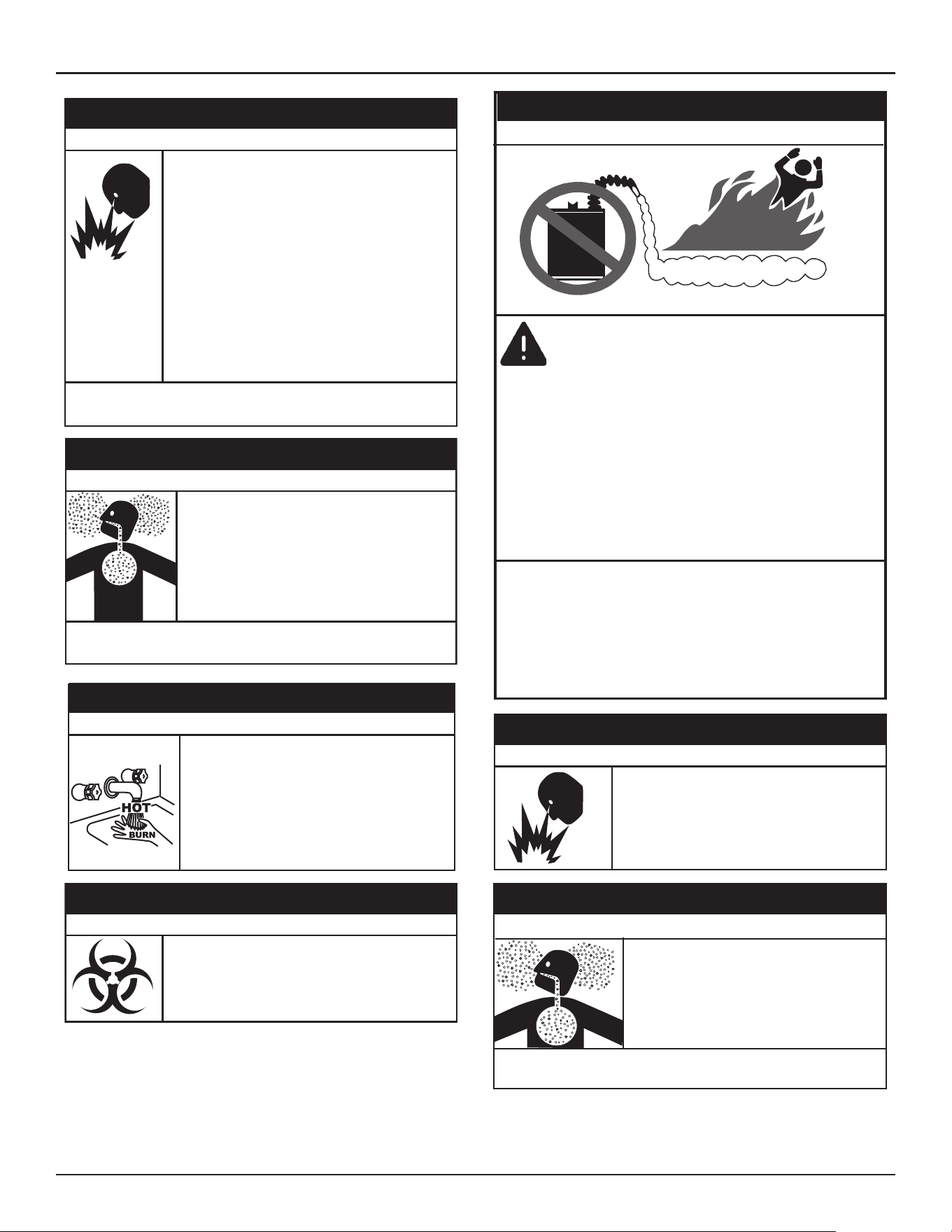
FLAMMABLES
Vapors from flammable
liquids may explode
and catch fire causing
death or sever burns.
Water heater has a main
burner and ignition device.
The ignition device:
1. Can come on at any time.
2. Will ignite flammable
vapors.
Do not use or store flammable
products, such as gasoline,
solvents, or adhesives in the
same room or area near the
water heater.
Keep flammable products:
1. Far away from heater.
2. In approved containers.
3. Tightly closed and
4. Out of children’s reach
Vapors:
1. Cannot be seen.
2. Are Heavier than air.
3. Go a long way on the floor.
4. Can be carried from other
rooms to the ignition
device by air currents.
Installation:
Do not install the water heater where flammable
products will be stored or used unless the main burner
and igniter are at least 18" (457 cm) above the floor.
This will reduce, but not eliminate the risk of vapors
being ignited by the main burner or hot surface igniter.
⚠
DANGER
Fire or Explosion Hazard
Flammable Vapors
Read the instruc�on manual before installing,
using, or servicing the water heater.
• Improper use can result in fire or explosion.
• Maintain required clearances to combustibles.
⚠
WARNING
Fire and Explosion Hazard
• Do not obstruct water heater air intake
with insula�ng blanket.
• Gas and carbon monoxide detectors are
available.
• Install water heater in accordance with the
instruc�on manual.
Breathing carbon monoxide can cause brain damage or death. Always read
and understand instruc�on manual.
⚠
WARNING
Breathing Hazard - Carbon Monoxide Gas
6 • Residential Gas Water Heaters
General Safety Information
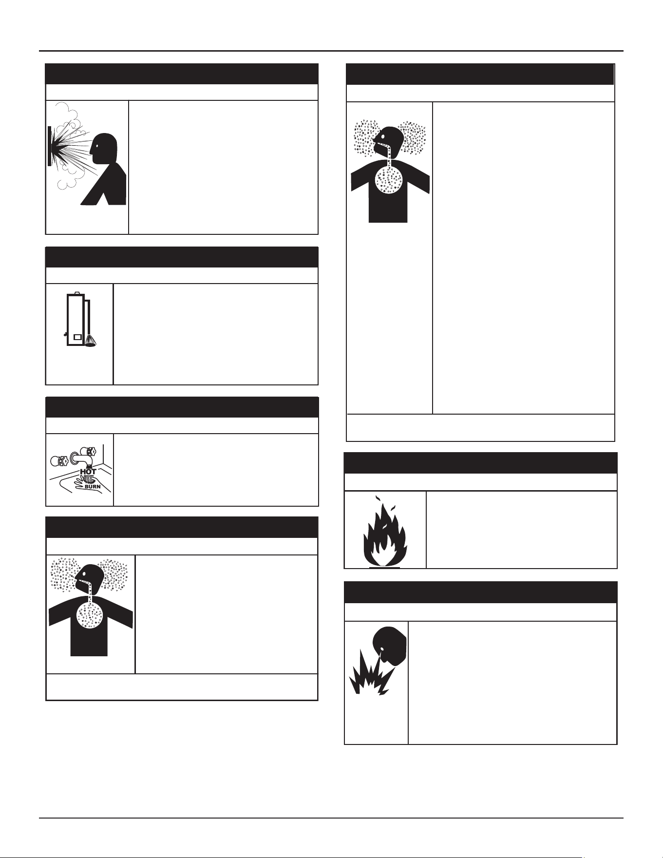
Normal opera�on of the water heater can cause
it to become sufficiently over-heated and/or
over-pressurized that it can explode, resul�ng in
property damage, sever injury, or death.
To avoid this hazard, you must install a properly-
sized temperature-pressure relief valve in opening
provided.
• The temperature-pressure relief valve must
comply with ANSI Z21.22-CSA 4.4 and ASME
code.
• Do not plug, block, or cap the discharge line.
⚠
WARNING
Explosion Hazard
Property Damage Hazard
While the water heater is in rou�ne opera�on, it can
release hot water from the temperature-pressure relief
valve discharge pipe in quan��es that could cause
damage to the surroundings.
Locate the water heater near an adequate drain and
in an area where water from the temperature-pres-
sure relief valve discharge pipe will not result in
damage to the area or the lower floors of the
structure.
⚠
CAUTION
⚠
DANGER
Burn Hazard
The discharge water from the temperature-pressure
relief valve is hot enough to cause burns.
Keep clear of the temperature-pressure relief valve
discharge outlet.
• Special considera�ons must be taken with
installa�ons above 10,100 (3,078 meters).
• Please contact an A. O. Smith qualified
service agent to obtain the proper setup
and instruc�ons before ligh�ng.
• Failure to implement the proper setup will
result in improper and inefficient opera�on
of the appliance, resul�ng in produc�on of
increased levels of carbon monoxide gas in
excess of the safe limits which could result
in serious personal injury or death.
Breathing carbon monoxide can cause brain damage or death. Always read
and understand instruc�on manual.
⚠
WARNING
Breathing Hazard - Carbon Monoxide Gas
Breathing carbon monoxide can cause brain damage or death. Always
read and understand instruc�on manual.
⚠
WARNING
Breathing Hazard - Carbon Monoxide Gas
• Install vent system in accordance with codes.
•
Do not operate water heater if any part has been
exposed to flooding or water damage.
• High altitude models should be installed at
elevations above 5,300 feet (1,615 m). For
operation above 10,100 feet (3,079 m), a high
altitude orifice must be installed.
• Do not operate if soot buildup is present.
• Do not obstruct water heater air intake with
insulating jacket.
• Do not place chemical vapor emitting products
near water heater.
•
Gas and carbon monoxide detectors are available.
• No vent damper installation is compatible with
this power vented water heater.
•
Do NOT elevate any portion of the field supplied
drain line beyond the 1/2” adapter above the
adapter. This must be true for the entire length
of the drain line including the exit into an
appropriate drain.
•
Condensate lines must be free and clear of debris
and must not allow back flow through the hose.
The condensate lines must be able to flow freely
to an appropriate drain.
• Do not allow condensate lines to become
crimped closed.
•
Analyze the entire vent system to make sure that
condensate will not become trapped in a section
of vent pipe and therefore reduce the open cross
sectional area of the vent.
• Contaminants in gas lines can cause fire or
explosions.
• Clean all gas piping before installation.
• Install drip leg in accordance with NFPA 54 or
CSA-B1491.
⚠
WARNING
Fire and Explosion Hazard
Gas piping can leak gas from fi�ngs and connec�ons if
it is not sealed properly. Gas leaks can cause fires and
explosions resul�ng in severe injury or death.
• Use joint compound or thread sealer tape compatible
with the type of gas you are using.
• Leak test all gas connections before placing the water
heater in operation.
• Disconnect gas piping at main gas shutoff valve before
leak testing.
• Install sediment trap in accordance with NFPA 54 or
CAN/CSA B149.1.
⚠
WARNING
Fire and Explosion Hazard
General Safety Information
Residential Gas Water Heaters • 7
Fire and Explosion Hazard
An improper field conversion from one
type of gas to another could cause
potentially dangerous conditions that may
cause an explosion or fire resulting in
property damage, bodily injury or death.
Do not attempt to convert a water heater
without consulting A. O. Smith.
⚠
WARNING
• Flue gases may escape if vent pipe is not
connected.
•
Be alert for obstructed, sooted, or deteriorated
vent system to avoid serious injury or death.
• Do not store corrosive chemicals in the vicinity
of the water heater.
• Chemical corrosion of the flue and vent system
can cause serious injury or death.
• Analyze the entire vent system to make sure
that condensate will not become trapped in a
section of vent pipe and therefore reduce the
open cross sectional area of the vent.
Breathing carbon monoxide can cause brain damage or death.
Always read and understand instruction manual.
⚠
WARNING
Breathing Hazard - Carbon Monoxide Gas
• The combustion chamber and burner sleeve and
housing become very hot during operation.
• Do not reach into the burner housing or
combustion chamber if the water heater is still
hot.
• Allow the water heater to cool and always use
gloves when handling the main burner.
⚠
CAUTION
Burn Hazard
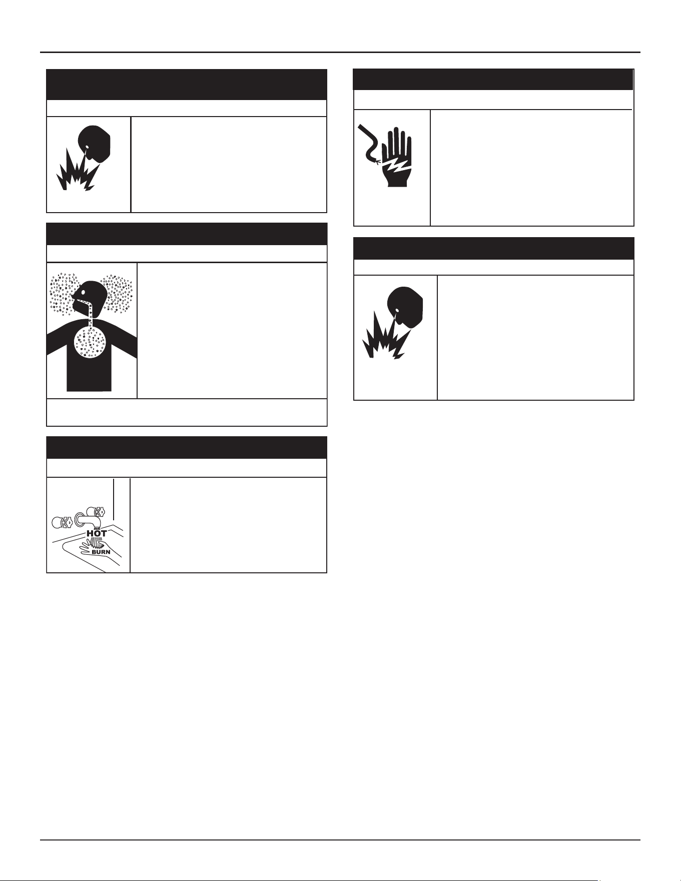
Servicing this water heater exposes you to
electrified components that can cause severe
injury or death if you touch them.
• Turn off power at the branch circuit breaker
serving the water heater before performing any
service.
• Label all wires prior to disconnecting when
performing service. Wiring errors can cause
improper and dangerous operation.
• Verify proper operation after servicing.
⚠
WARNING
Electrical Shock Hazard
Jumping out control circuits or components can
result in property damage, personal injury or death.
• Service should only be performed by a qualified
service technician using proper test equipment.
• Altering the water heater controls and/or wiring in
any way could result in permanent damage to the
controls or water heater and is not covered under
the limited warranty.
• Any bypass or alteration of the water heater
controls and/or wiring will result in voiding the
appl
iance warranty.
⚠
WARNING
Safety Hazard

8 • Residential Gas Water Heaters
INTRODUCTION
Thank You for purchasing this water heater. Properly installed and
maintained, it should give you years of trouble free service.
ABBREVIATIONS USED
Abbreviations found in this Instruction Manual include :
• ANSI - American National Standards Institute
• ASME - American Society of Mechanical Engineers
• AHRI - Air-Conditioning, Heating and Refrigeration Institute
• ASSE - Performance Requirements for Water Temperature Limiting
Devices
• NEC - National Electrical Code
• NFPA - National Fire Protection Association
• UL - Underwriters Laboratory
• CSA - Canadian Standards Association
QUALIFICATIONS
Qualified Installer or Service Agency
Installation and service of this water heater requires ability equivalent to
that of a Qualified Agency (as defined by ANSI below) in the field involved.
Installation skills such as plumbing, air supply, venting, gas supply and
electrical supply are required in addition to electrical testing skills when
performing service.
ANSI Z223.1 2006 Sec. 3.3.83: “Qualified Agency” - “Any individual, firm,
corporation or company that either in person or through a representative is
engaged in and is responsible for (a) the installation, testing or replacement
of gas piping or (b) the connection, installation, testing, repair or servicing
of appliances and equipment; that is experienced in such work; that is
familiar with all precautions required; and that has complied with all the
requirements of the authority having jurisdiction.”
If you are not qualified (as defined by
ANSI
above) and licensed or certified
as required by the authority having jurisdiction to perform a given task do
not attempt to perform any of the procedures described in this manual. If
you do not understand the instructions given in this manual do not attempt
to perform any procedures outlined in this manual.
PREPARING FOR THE INSTALLATION
1. Read the entire manual before attempting to install or operate the
water heater. Pay close attention to the
General Safety Information
(page 3). If you don’t follow the safety rules, the water heater may
not operate safely. It could cause property damage, injury and/or death.
2. This manual contains instructions for the installation, operation, and
maintenance of the water heater. It also contains warnings throughout
the manual that you must read and be aware of. All warnings and all
instructions are essential to the proper operation of the water heater
and your safety.
Detailed installation diagrams are also found in this manual. These
diagrams will serve to provide the installer with a reference. It is
essential that all venting, water piping, gas piping and wiring be
installed as shown.
3. Particular attention should be given to the installation of thermometers
at the locations indicated in the piping diagrams as these are necessary
for checking the operation of the water heater.
4. The principal components of the water heater are identified in
Features And Components on Page 10 & Page 11 in this manual. Use
this reference to locate and identify various components on the water
heater.
5. See the
Installation Checklist
(page 61)
and
Troubleshooting
(page
61). By using this checklist the user may be able to make minor
operational adjustments and avoid unnecessary service calls. However,
service and diagnostic procedures should only be performed by a
Qualified Service Agency.
Note:
Costs to correct installation errors are not covered.
6. Be sure to turn off power when working on or near the electrical system
of the water heater. Never touch electrical components with wet hands
or when standing in water.
7. The installation must conform to all instructions contained in this
manual and the local code authority having jurisdiction. These shall be
carefully followed in all cases. Authorities having jurisdiction should be
consulted before installation begins if there are any questions regarding
compliance with local, state or national codes.
8. In the absence of local codes, the installation must comply with the
current editions of the
National Fuel Gas Code, ANSI Z223.1/NFPA
54
and the
National Electrical Code, NFPA 70
or
CAN/CSA-B149.1
,
the
Natural Gas and Propane Installation Code
and
CSA C22.1
, the
Canadian Electrical Code
. All documents are available from the Canadian
Standards Association, 8501 East Pleasant Valley Road, Cleveland,
OH 44131. NFPA documents are also available from the National Fire
Protection Association, 1 Batterymarch Park, Quincy, MA 02269.
9. The water heater, when installed, must be electrically grounded in
accordance with the local codes or in the absence of local codes: current
edition of the
Canadian Electrical Code CSA C22.1, or Part I ”National
Electrical Code”, NFPA 70.
10. If after reading this manual you have any questions or do not understand
any portion of the instructions, call the toll free number found on the
warranty sheet provided with the water heater. In order to expedite
your request, please have the full Model, Serial and Series number of
the water heater you are working with available for the technician. This
information is located on the water heater’s rating plate.
11. Carefully plan the placement of the water heater. Examine the location
to ensure that it complies with the requirements in
Locating The Water
Heater
(page 15).

Introduction
Residential Gas Water Heaters • 9
12. For installation in California this water heater must be braced or
anchored to avoid falling or moving during an earthquake. See
instructions for correct installation procedures. Instructions may be
obtained from California Office of the State Architect, 1102 Q Street,
Suite 5100, Sacramento, CA 95811.
13. Massachusetts Code requires this water heater to be installed in
accordance with
Massachusetts 248-CMR 2.00: State Plumbing Code
and
248-CMR 5
. See
Massachusetts Installation Requirements
(page
26).
Recommended Accessories:
• A metal drain pan.
• Automatic water shut-off device.
• Pressure Reducing Valve.
• Thermal Expansion Tank.
• Thermostatic mixing valves at each point of use.
• Fuel gas and carbon monoxide detector.
10 • Residential Gas Water Heaters
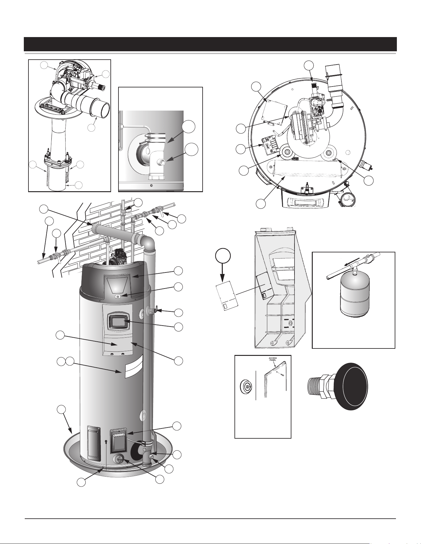
FEATURES AND COMPONENTS
3
2 4
5
6
1
**18
**17
17
28
25
26
27
24
23
22
21
20
11
12
16
7**
13
19
15
10
8
(Behind Plastic
Enclosure)
18
9
34
33
32
31
30
29
36
37
Install thermal expansion
tank if the water heater is
installed in a closed water
system.
Caution:
This access panel
covers a 2” NPT plug that was
required during the manufacturing
of this water heater. This 2” NPT
flange is not a cleanout fitting,
removing the 2” NPT plug and
using this fitting as a cleanout
could void your warranty.
Vacuum Relief Valve
*Install per local codes
* CAUTION HARNESS HAS 120 VAC. IN OPERATION.
** See
Venting Installation
(page 27) and Condensate Piping for more information.
See the manufacturer’s installation instructions for installing the Leak Detection Module
(LDM).
Figure 1. 50-Gallon Unit
Features and Components
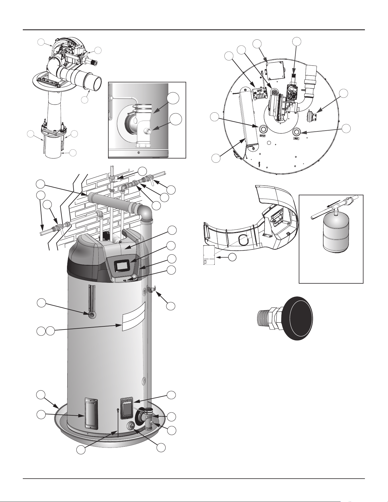
Residential Gas Water Heaters • 11
3
2 4
5
6
1
**18
**17
17
28
25
26
27
24
23
22
10
11
12
16
7**
13
8
19
15
14*
18
9
20
21
33
34
36
35
30
29
31
32
37
Install thermal expansion
tank if the water heater is
installed in a closed water
system.
Vacuum Relief Valve
*Install per local codes
* CAUTION HARNESS HAS 120 VAC. IN OPERATION.
** See
Venting Installation
(page 27) and Condensate Piping for more information.
See the manufacturer’s installation instructions for installing the Leak Detection Module
(LDM).
Figure 2. 75-Gallon Unit
12 • Residential Gas Water Heaters
Features and Components
1. Blower Assembly
2. Flame Sensor
3. Burner Assembly
4. Igniter Assembly
5. Intake-Air Fitting
6. Gas Control Valve Assembly
7. **Vent Terminal
8. Hot Water Outlet
9. Hot Water Shutoff Valve (field-supplied)
10. Temperature Probe
11. Rating Plate
12. Labels
13. Drain Pan
14. Cleanout Access Door
15. Leak Detection Module
16. Drain Valve
17. **Condensate Drain Outlet
18. **Exhaust Elbow Assembly
19. Blocked Outlet Switch/ Access Door
20. Display Enclosure
21. UIM (user interface module)
22. T/P Relief Valve
23. Enable / Disable Switch
24. Top Plastic Enclosure
25. Union (field-supplied)
26. Cold Water Inlet
27. Cold Water Shutoff Valve (field-supplied)
28. Main Manual Gas Shutoff Valve (field-
supplied)
29. Control Board Enclosure
30. Hot Water Outlet
31. Spark Igniter Transformer
32. Powered Anode Rod
33. Junction Box
34. Gas Supply Connection
35. Blocked Inlet Switch
36. Cold Water Inlet (field-supplied)
37. Flexible Memory Module (FMM)
Table 1. Recovery Capacities
Input Recovery Capacities
Rating
(Btu/hr)
Rating
(kW)
Temp.
Rise
F 30 40 50 60 70 80 90 100 110 120 130 140
C 17 22 28 33 39 44 50 56 61 67 72 78
100,000 29.3
GPH 387 291 233 194 166 145 129 116 106 97 90 83
LPH 1465 1102 882 734 628 549 488 439 401 367 341 314
Recovery capacity based on 96% thermal efficiency.
Table 2. Capacity, Gas And Electrical Characteristics
Nominal Capacity Rated Capacity *Manifold Pressure Electrical Characteristics
U.S. Gals. Liters U.S. Gals. Liters Gas Type "WC kPA Volts/Hz Amperes
50 189 49 186 Nat./LP 0 0 120/60 <5
75 284 74 280 Nat./LP 0 0 120/60 <5
*The manifold pressure is the factory setting and is not adjustable. A negative pressure will be seen with just the blower running without the Gas Control Valve open.
All models - Maximum Supply Pressure: 14 inches W.C. (3.48 kPa)
Minimum Supply Pressure for Natural Gas: 3.50 inches W.C. (.87 kPa)
Minimum Supply Pressure for Propane Gas: 8.00 inches W.C. (1.99 kPa)
Minimum pressure must be maintained under both load and no load (dynamic and static) conditions.
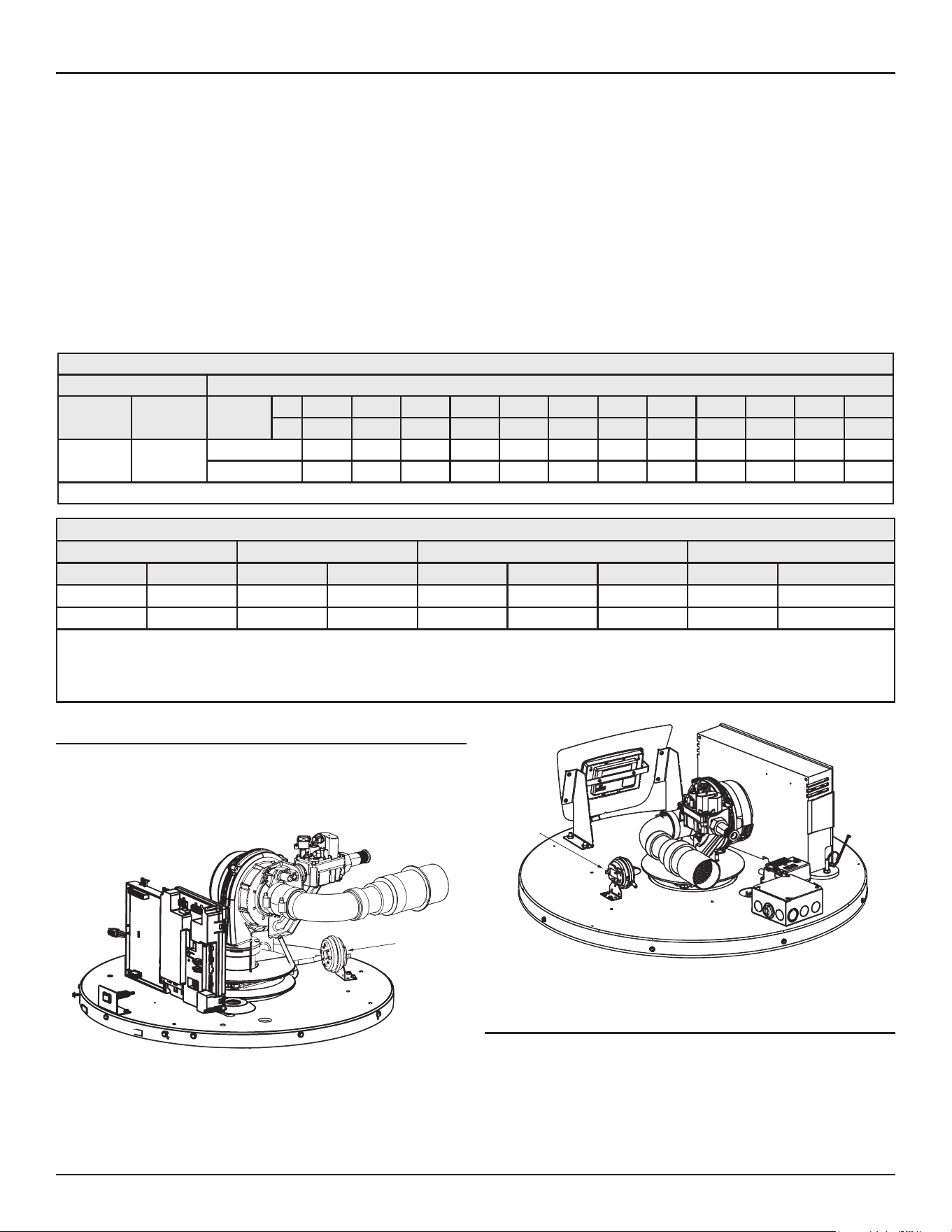
CONTROLS AND SWITCHES
This model is provided with two pressure switches. These switches are
essential to the safe and proper operation of the unit. The controller is
set up to shut the unit down whenever there is a failure of either of the
switches. It is important to understand the purpose of both switches.
Blocked
Intake
Switch
Figure 3. Blocked Intake Switch on 50 Gallon Unit
Blocked
Intake
Switch
Figure 4. Blocked Intake Switch on 75 Gallon Unit
Blocked Outlet Switch
The Blocked Exhaust Switch is set up to shut the unit off when a build-
up of positive pressure in the exhaust vent pipe occurs. This switch is a
positive pressure switch that requires an increase in pressure to change
the electrical contacts from normally closed to open. When this switch
prevents the unit from igniting, most likely the exhaust is blocked by some
means. Check to see if the condensate is allowed to flow freely from the
exhaust elbow and for obstructions in the exhaust venting and exhaust vent

Features and Components
Residential Gas Water Heaters • 13
terminal. Also verify that the vent length does not exceed the maximum
allowed as shown in the Vent Section of this manual.
Blocked Intake Switch
The Blocked Intake Switch is set up to shut the unit off when a build-up of
negative pressure in the intake air pipe occurs. This switch is a negative
pressure switch that requires an increase in negative pressure to change the
electrical contacts from normally closed to open. The switch is connected to
the pressure tap on the PVC pipe connected to the inlet of the blower. When
this switch prevents the unit from igniting, most likely the intake is blocked.
Verify that the screen on the intake air connection (conventional vent),
the intake air pipe and termination (direct vent installations) are free of
obstructions that may prevent air from entering the unit. Ensure the screen
on intake air connection has been removed on direct vent installations.
See
Figure 17
(page 29). Also verify the intake air pipe length does not
exceed the maximum allowed as shown in
Venting Installation
(page 27).
Water Heating Enable/Disable Switch
Important: The Enable/Disable switch listed in this manual is
NOT
an
“on/off” switch and does not disconnect 120 volt power to
the Control Board Enclosure and other heater components.
Water Heater’s Enable/Disable Switch. When in the “Disabled” position the
switch removes electrical power from the gas valve so that water heating
is disabled. The display, CSC, TRC, and other electrical components will still
be energized and the display will read “Water Heating Disabled”.
OTHER FEATURES
Spark Igniter - The Spark Igniter is a device that ignites the main burner
by spark. When high voltage is applied to the igniter, spark is generated
to ignite the main burner.
NFC Board - The Near Field Communication (NFC) Board is located inside
the plastic display enclosure. The NFC Board enables an NFC device to
communicate information with the heater.
DO NOT REMOVE OR DAMAGE
THE NFC BOARD
.
Powered Anode Rod - The models covered in this manual are equipped
with a powered (non-sacrificial) anode rod. Protective current is fed by
the control system to the titanium electrode at the end of the anode rod.
This current flows through the water to the conductive surfaces inside
the storage tank which diminishes the corrosive effect of water when it
comes in contact with steel.
Flame Sensor - The control system monitors the flame sensor to confirm
a flame is present at the main burner. If a flame is not verified during the
ignition trial period, the control system will immediately deenergize the
gas valve.
Gas Valve - This heater is equipped with an adaptive gas valve system with
a motor driven throttle suitable for natural or propane. It is controlled by
the CSC in conjunction with the TRC.
Control Board Enclosure - This enclosure houses the control system’s
temperature regulation control (TRC), combustion and safety control (CSC).
14 • Residential Gas Water Heaters
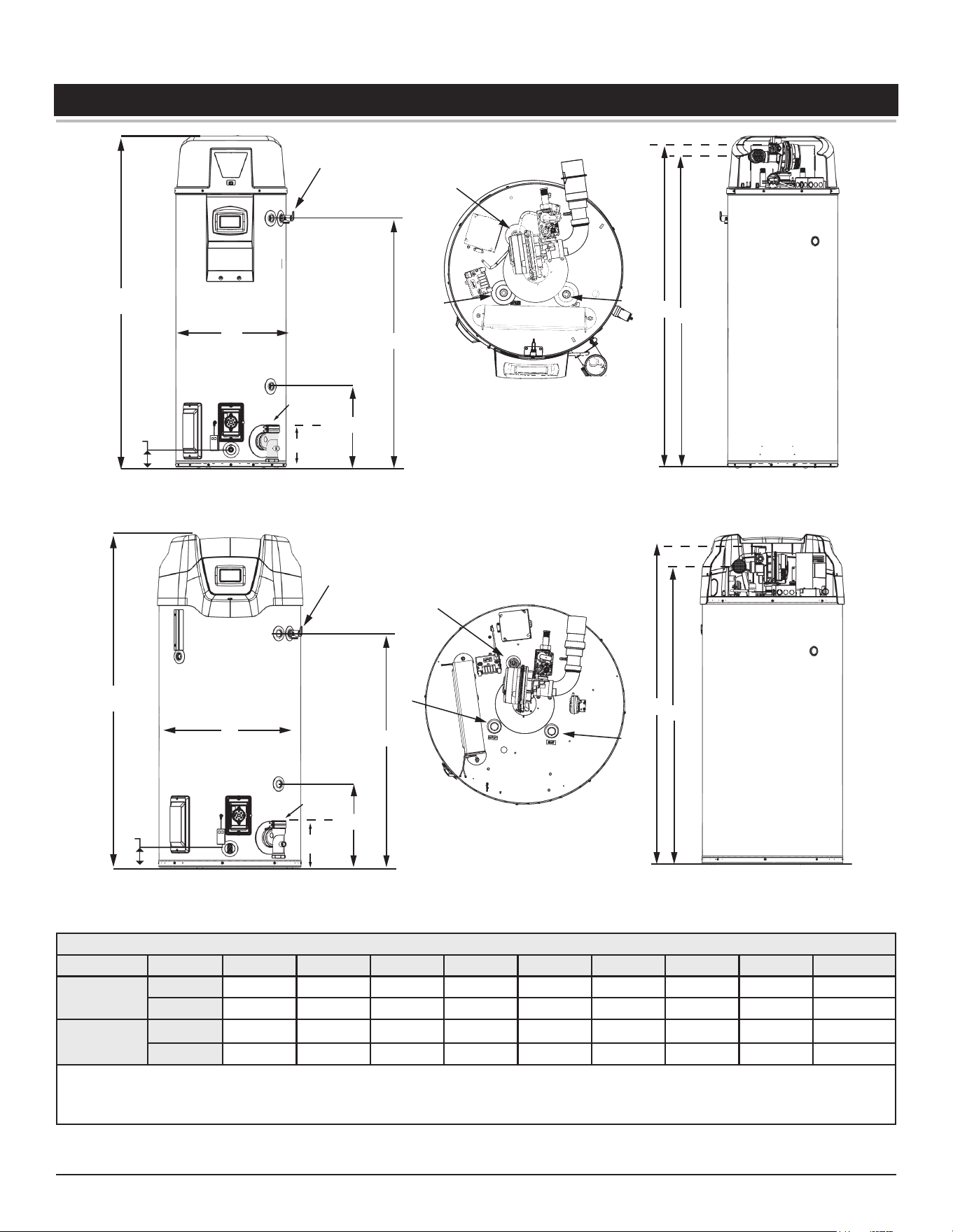
INSTALLATION CONSIDERATIONS
A
E
C
D
T&P
UPPER SIDE CONNECT
B
FRONT VIEW
DRAIN
DIAMETER
*INSTALL IN ACCORDANCE WITH LOCAL CODES
TOP VIEW
BACK VIEW
INLET
ANODE
OUTLET
I
H
G
GAS PIPING CONNECTION
AIR INTAKE CONNECTION
EXHAUST
VENT
CONNECTION
LOWER SIDE
CONNECT
Figure 5. Rough In Dimensions: 50 Gallon Unit
A
E
C
D
T&P
UPPER SIDE
CONNECT
B
LOWER SIDE
CONNECT
FRONT VIEW
DRAIN
DIAMETER
*INSTALL IN ACCORDANCE WITH LOCAL CODES
TOP VIEW
BACK VIEW
INLET
ANODE
OUTLET
I
H
G
GAS PIPING CONNECTION
AIR INTAKE CONNECTION
EXHAUST
VENT
CONNECTION
Figure 6. Rough In Dimensions: 75 Gallon Unit
Table 3. Rough-In-Dimensions
Model Units A B C D E F G H I
50G
Inches 66 3/4 49 1/4 22 15 3/4 3 8 8 62 65
cm 169.5 125.09 55.88 40.00 7.62 20.32 20.32 157.48 165.1
75G
Inches 65 1/4 45 5/8 27 3/4 16 3 3/4 8 8 59 60
cm 165.7 115.9 70.5 40.6 9.4 20.3 20.1 145.7 149.8
Top Inlet and Outlet: 50G - 3/4” NPT; 75G - 1” NPT
Side Inlet and Outlet: 3/4” NPT
Gas Inlet: 1/2” NPT
Condensate drain outlet: 1/2” NPT
Installation Considerations
Residential Gas Water Heaters • 15
LOCATING THE WATER HEATER
Carefully choose a location for the new water heater. The placement is a
very important consideration for the safety of the occupants in the building
and for the most economical use of the water heater.
CAUTION
Property Damage Hazard
Over me, the tank and fings of the water heater
can begin to leak and cause water damage.
• Locate the water heater near an adequate drain
and in an area where water leakage from the
heater or connecons will not result in damage to
the area or the lower floors of the structure.
• Install the water heater in a drain pan.
Whether replacing an existing water heater or installing the water heater
in a new location observe the following critical points:
1. The water heater must be located indoors.
2. The water heater must not be located in an area where it will be subject
to freezing temperatures.
3. Locate the water heater so it is protected and not subject to physical
damage by a moving vehicle.
4. Locate the water heater on a level surface.
5. Locate the water heater near a floor drain. The water heater should be
located in an area where leakage of the tank or connections will not
result in damage to the area adjacent to the water heater or to lower
floors of the structure. When such locations cannot be avoided, it is
recommended that a metal drain pan, piped to adequate drain, be
installed under the water heater. Drain pan should be fabricated with
sides at least 2” deep with diameter at least 2” greater than diameter
of heater.
6. Locate the water heater close to the point of major hot water usage.
7. Locate the water heater close to a 120 VAC power supply. See
Power
Supply
(page 20) for requirements.
8. Locate the water heater where an adequate supply of fresh air for
combustion and ventilation can be obtained. See
Combustion Air And
Ventilation
(page 17)
and
Venting Installation
(page 27).
9. Locate the water heater where the vent and intake air piping, when
installed, will remain within the maximum equivalent lengths allowed.
See
Venting Installation
(page 27).
10. Do not locate the water heater where noise (such as the Combustion
Blower) during normal operation will be objectionable in adjacent areas.
11. Do not locate the water heater where the subsequent installation of
the vent (exhaust) or intake air terminations would be objectionable
due to noise at the termination(s). This includes locations close to or
across from windows and doors. See
Venting Installation
(page 27).
Do not locate water heater in areas where flammable liquids (vapors)
are likely to be present or stored (garages, storage and utility areas, etc.):
Flammable liquids (such as gasoline, solvents, propane (LP or butane, etc.)
and other substances (such as adhesives, etc.) emit flammable vapors
which can be ignited by a gas water heater’s ignition device or main
burner. The resulting flashback and fire can cause death or serious burns
to anyone in the area.
Read instruction manual before installing, using or servicing water
heater.
⚠
WARNING
Fire or Explosion Hazard
Under certain circumstances, the water heater can
explode and catch fire, resul�ng in property damage,
personal injury, or death.
Do the following to avoid these condi�ons:
• Do not store or use gasoline or other flammable
vapors and liquids in the vicinity of this or any other
appliance.
• Avoid all ignition sources if you smell gas.
• Do not expose water heater controls to excessive gas
pressure.
• Use only the gas shown on the water heater rating
label.
• Maintain required clearances to combustibles.
• Keep ignition sources away from faucets after
extended periods of non-use.
16 • Residential Gas Water Heaters
Installation Considerations
FLAMMABLES
Vapors from flammable
liquids may explode
and catch fire causing
death or sever burns.
Water heater has a main
burner and ignition device.
The ignition device:
1. Can come on at any time.
2. Will ignite flammable
vapors.
Do not use or store flammable
products, such as gasoline,
solvents, or adhesives in the
same room or area near the
water heater.
Keep flammable products:
1. Far away from heater.
2. In approved containers.
3. Tightly closed and
4. Out of children’s reach
Vapors:
1. Cannot be seen.
2. Are Heavier than air.
3. Go a long way on the floor.
4. Can be carried from other
rooms to the ignition
device by air currents.
Installation:
Do not install the water heater where flammable
products will be stored or used unless the main burner
and igniter are at least 18" (457 cm) above the floor.
This will reduce, but not eliminate the risk of vapors
being ignited by the main burner or hot surface igniter.
⚠
DANGER
Fire or Explosion Hazard
Flammable Vapors
When the water heater is installed directly on carpeting, the water heater
shall be installed on a metal or wood panel extending beyond the full width
and depth of the water heater by at least 3 in (76.2 mm) in any direction
or, if the water heater is installed in an alcove or closet, the entire floor
shall be covered by the panel. The panel must be strong enough to carry
the weight of the heater when full of water.
Read the instruc�on manual before installing,
using, or servicing the water heater.
• Improper use can result in fire or explosion.
• Maintain required clearances to combustibles.
⚠
WARNING
Fire and Explosion Hazard
Minimum clearances between the water heater and combustible
construction are 0 inch at the sides and rear, 5.5” (14.0 cm) from the
front and 18” (45.7 cm) from the top. (Standard clearance.) If clearances
stated on the heater differ from standard clearances, install water heater
according to clearances stated on the heater.
Adequate clearance 30” (76 cm) for servicing this water heater should be
considered before installation, such as changing the anode rods, control
system components and gas control valve.
A minimum clearance of 5.5” (14.0 cm) must be allowed for access to
replaceable and/or serviceable parts such as the thermostats, drain valve,
condensate drain, temperature-pressure relief valve, clean out opening,
and the vent connection (exhaust elbow).
When installing the heater, consideration must be given to proper location.
Location selected should be as close to the wall as practicable and as
centralized with the water piping system as possible.
Celing
Front View
0 in
(0 cm) MIN.
*0 in
(0 cm) MIN.
*For service access.
Le
Wall
Right
Wall
Top View
of Closet
Without Door
Water
Heater
0 in
(0 cm) MIN.
0 cm
(0 in) MIN.
Top View
of Closet
With Door
5.5 in
(14 cm) MIN.
*18 in
(46 cm)
Water
Heater
Figure 7. Enclosure Installation Clearances
INSULATION BLANKETS
• Do not obstruct water heater air intake
with insula�ng blanket.
• Gas and carbon monoxide detectors are
available.
• Install water heater in accordance with the
instruc�on manual.
Breathing carbon monoxide can cause brain damage or death. Always read
and understand instruc�on manual.
⚠
WARNING
Breathing Hazard - Carbon Monoxide Gas
Insulation blankets are available to the general public for external use on
gas water heaters but are not necessary with these products. The purpose
of an insulation blanket is to reduce the standby heat loss encountered with
storage tank heaters. Your water heater meets or exceeds the Energy Policy
Act standards with respect to insulation and standby loss requirements,
making an insulation blanket unnecessary.
Should you choose to apply an insulation blanket to this heater, you should
follow these instructions (For identification of components mentioned
below. See
Figure 1
(page 10) and
Figure 2
(page 11). Failure to follow
these instructions can restrict the air flow required for proper combustion,
potentially resulting in fire, asphyxiation, serious personal injury or death.
•
Do not
apply insulation to the top of the water heater, as this will
interfere with safe operation of the blower assembly.
•
Do not
cover the control system LCD on top of the water heater.
•
Do not
cover the outer door, thermostat or temperature & pressure
relief valve.
•
Do not
cover the instruction manual. Keep it on the side of the
water heater or nearby for future reference.
•
Do
obtain new warning and instruction labels from the manufacturer
for placement on the blanket directly over the existing labels.
•
Do
inspect the insulation blanket frequently to make certain it does
not sag, thereby obstructing combustion air flow.
Installation Considerations
Residential Gas Water Heaters • 17
COMBUSTION AIR AND VENTILATION
A gas water heater cannot operate properly without the correct amount of
air for combustion. Do not install in a confined area such as a closet, unless
you provide air as shown in
Locating The Water Heater
(page 15). Never
obstruct the flow of ventilation air. If you have any doubts or questions
at all, call your gas supplier. Failure to provide the proper amount of
combustion air can result in a fire or explosion and cause death, serious
bodily injury, or property damage.
• Install water heater in accordance with
the Instruction Manual and NFPA 54 or
CAN/CSA-B149.1.
• To avoid injury, combustion and ventilation air
must be taken from outdoors.
• Do not place chemical vapor emitting products
near water heater.
Breathing carbon monoxide can cause brain damage or death. Always
read and understand instruc�on manual.
⚠
WARNING
Breathing Hazard - Carbon Monoxide Gas
VENTILATION
AIR
OPENING
12” max.
(30.5 cm)
12” max.
(30.5 cm)
100 sq in
(645 sq cm)
FRONT VIEW OF DOOR
3”
(7.6 cm)
Rectangular
Air Duct
Figure 8. Enclosure Door Vent Clearances
If this water heater will be used in beauty shops, barber shops, cleaning
establishments, or self-service laundries with dry cleaning equipment, it
is imperative that the water heater(s) be installed direct vent so that all
air for combustion and ventilation is taken from outdoors.
Propellants of aerosol sprays and volatile compounds, (cleaners, chlorine
based chemicals, refrigerants, etc.) in addition to being highly flammable
in many cases, will also react to form corrosive acids when exposed to the
combustion products of the water heater. The results can be hazardous,
and also cause product failure.
UNCONFINED SPACE
An Unconfined Space is one whose volume is not less than 50 cubic feet
per 1,000 Btu/hr (4.8 cubic meters per kW) of the total input rating of
all appliances installed in the space. Rooms communicating directly with
the space, in which the appliances are installed, through openings not
furnished with doors, are considered a part of the unconfined space.
Makeup air requirements for the operation of exhaust fans, kitchen
ventilation systems, clothes dryers and fireplaces shall also be considered
in determining the adequacy of a space to provide combustion, ventilation
and dilution air.
UNUSUALLY TIGHT CONSTRUCTION
In unconfined spaces in buildings, infiltration may be adequate to provide
air for combustion, ventilation and dilution of flue gases. However, in
buildings of unusually tight construction (for example, weather stripping,
heavily insulated, caulked, vapor barrier, etc.) additional air must be
provided using the methods described in the Confined Space section
that follows.
CONFINED SPACE
A Confined Space is one whose volume is less than 50 cubic feet per 1,000
Btu/hr (4.8 cubic meters per kW) of the total input rating of all appliances
installed in the space.
Openings must be installed to provide fresh air for combustion, ventilation
and dilution in confined spaces. The required size for the openings is
dependent on the method used to provide fresh air to the confined space
and the total Btu/hr input rating of all appliances installed in the space.
DIRECT VENT APPLIANCES
Appliances installed in a Direct Vent configuration that derive all air for
combustion from the outdoor atmosphere through sealed intake air piping
are not factored in the total appliance input Btu/hr calculations used to
determine the size of openings providing fresh air into confined spaces.
EXHAUST FANS
Where exhaust fans are installed, additional air shall be provided to replace
the exhausted air. When an exhaust fan is installed in the same space with
a water heater, sufficient openings to provide fresh air must be provided
that accommodate the requirements for all appliances in the room and the
exhaust fan. Undersized openings will cause air to be drawn into the room
through the water heater’s vent system causing poor combustion. Sooting,
serious damage to the water heater and the risk of fire or explosion may
result. It can also create a risk of asphyxiation.
LOUVERS AND GRILLES
The free areas of the fresh air openings in the instructions that follow do
not take in to account the presence of louvers, grilles or screens in the
openings.
The required size of openings for combustion, ventilation and dilution air
shall be based on the net free area of each opening. Where the free area
through a design of louver or grille or screen is known, it shall be used in
calculating the size of opening required to provide the free area specified.
Where the louver and grille design and free area are not known, it shall
be assumed that wood louvers will have 25% free area and metal louvers
and grilles will have 75% free area. Non motorized louvers and grilles shall
be fixed in the open position.
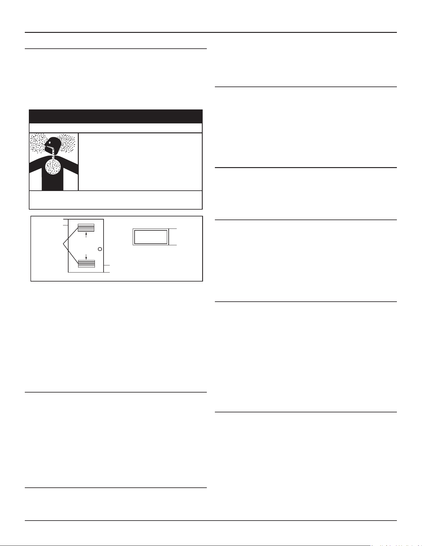
FRESH AIR OPENINGS FOR CONFINED SPACES
The following instructions shall be used to calculate the size, number and
placement of openings providing fresh air for combustion, ventilation
and dilution in confined spaces. The illustrations shown in this section of
the manual are a reference for the openings that provide fresh air into
confined spaces only. Do not refer to these illustrations for the purpose of
vent installation. See
Venting Installation
(page 27) for complete venting
installation instructions.
18 • Residential Gas Water Heaters
Installation Considerations
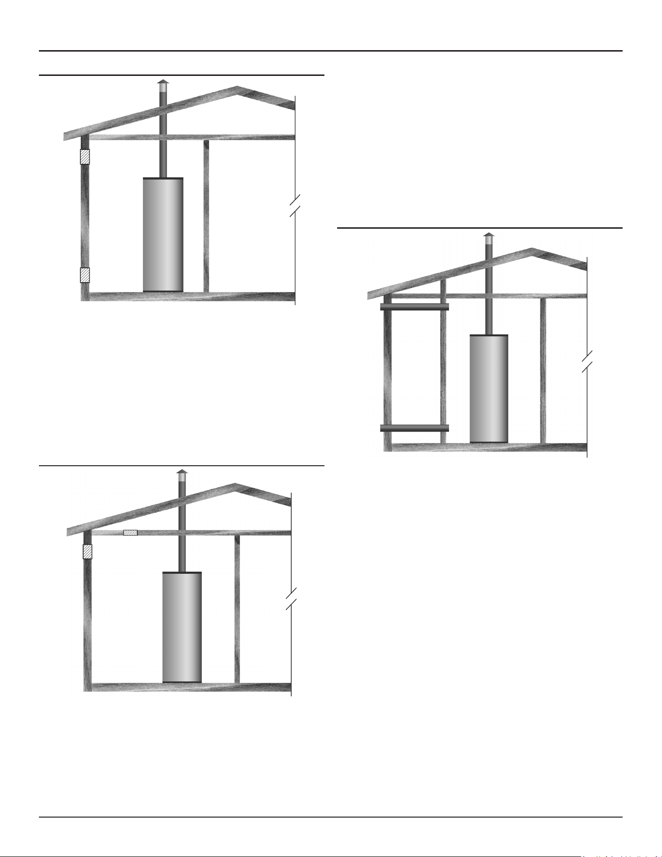
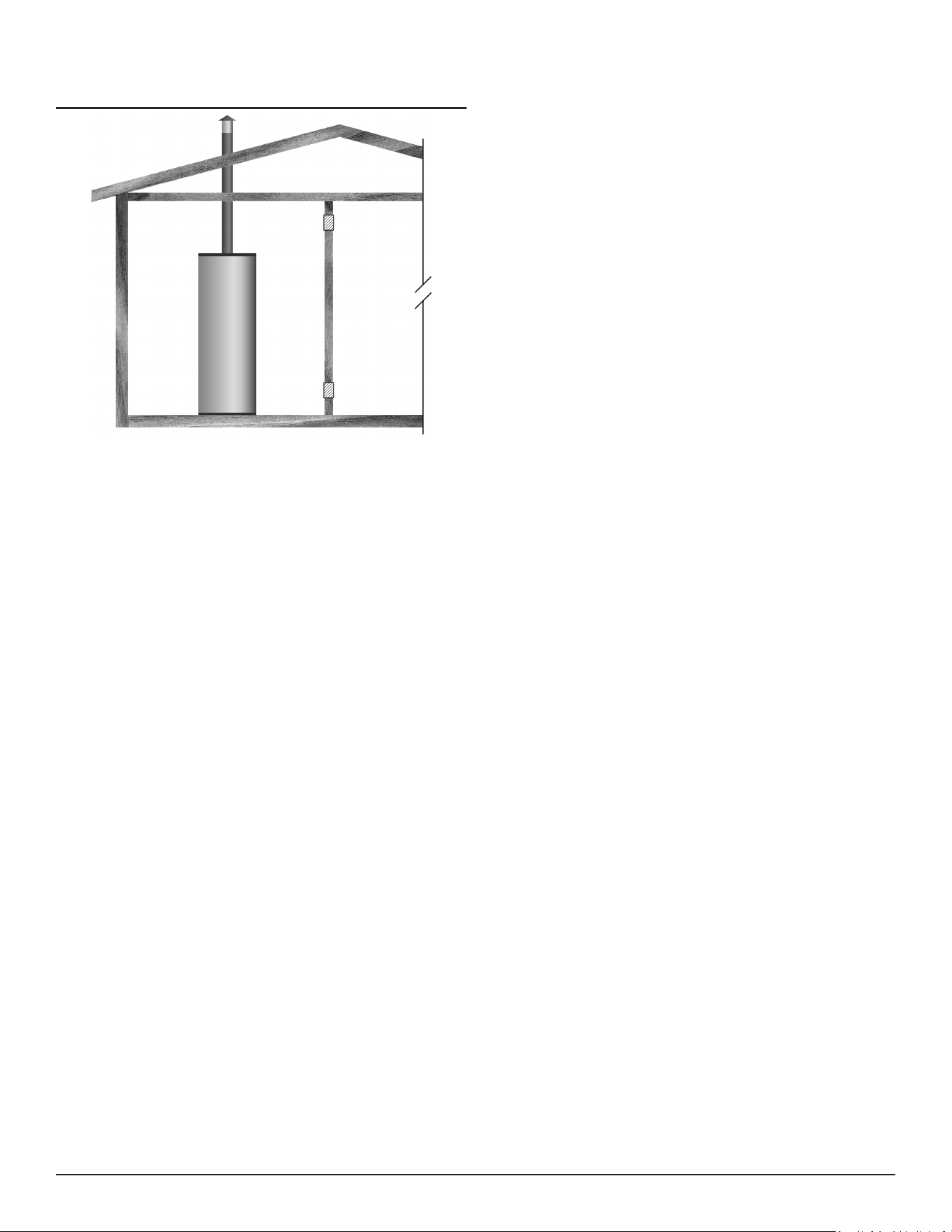
Outdoor Air Through Two Openings
Figure 9. Outdoor Air Through Two Openings
The confined space shall be provided with two permanent openings, one
commencing within 12 inches (300 mm) of the top and one commencing
within 12 inches (300 mm) of the bottom of the enclosure. The openings
shall communicate directly with the outdoors. See
Figure 9
.
Each opening shall have a minimum free area of 1 square inch per 4,000
Btu/hr (550 mm
2
per kW) of the aggregate input rating of all appliances
installed in the enclosure. Each opening shall not be less than 100 square
inches (645 cm
2
).
Outdoor Air Through One Opening
Figure 10. Outdoor Air Through One Opening
Alternatively a single permanent opening, commencing within 12 inches
(300 mm) of the top of the enclosure, shall be provided. See
Figure
10
. The water heater shall have clearances of at least 1 inch (25 mm)
from the sides and back and 6 inches (150 mm) from the front of the
appliance. The opening shall directly communicate with the outdoors or
shall communicate through a vertical or horizontal duct to the outdoors
or spaces that freely communicate with the outdoors and shall have a
minimum free area of the following:
1. 1 square inch per 3000 Btu/hr (733 mm
2
per kW) of the total input
rating of all appliances located in the enclosure.
2. Not less than the sum of the areas of all vent connectors in the space.
Outdoor Air Through Two Horizontal Ducts
Figure 11. Outdoor Air Through Two Horizontal Ducts
The confined space shall be provided with two permanent horizontal
ducts, one commencing within 12 inches (300 mm) of the top and one
commencing within 12 inches (300 mm) of the bottom of the enclosure.
The horizontal ducts shall communicate directly with the outdoors. See
Figure 11
.
Each duct opening shall have a minimum free area of 1 square inch per
2,000 Btu/hr (1100 mm
2
per kW) of the aggregate input rating of all
appliances installed in the enclosure.
When ducts are used, they shall be of the same cross sectional area as the
free area of the openings to which they connect. The minimum dimension
of rectangular air ducts shall be not less than 3 inches.
Residential Gas Water Heaters • 19
Air From Other Indoor Spaces
Figure 12. Air From Other Indoor Spaces
The confined space shall be provided with two permanent openings, one
commencing within 12 inches (300 mm) of the top and one commencing
within 12 inches (300 mm) of the bottom of the enclosure. See
Figure 12
.
Each opening shall communicate directly with an additional room(s) of
sufficient volume so that the combined volume of all spaces meets the
criteria for an Unconfined Space.
Each opening shall have a minimum free area of 1 square inch per 1,000
Btu/hr (2200 mm
2
per kW) of the aggregate input rating of all appliances
installed in the enclosure. Each opening shall not be less than 100 square
inches (645 cm
2
).
20 • Residential Gas Water Heaters
INSTALLATION REQUIREMENTS
CHEMICAL VAPOR CORROSION
Corrosion of the flue-ways and vent system may occur if air for combustion
contains certain chemical vapors. Such corrosion may result in failure and
risk of asphyxiation.
Spray can propellants, cleaning solvents, refrigerator and air conditioning
refrigerants, swimming pool chemicals, calcium and sodium chloride (water
softener salt), waxes, and process chemicals are typical compounds which
are potentially corrosive.
Do not store products of this sort near the heater. Also, air which is brought
in contact with the heater should not contain any of these chemicals. If
necessary, uncontaminated air should be obtained from remote or outside
sources. The limited warranty is voided when failure of water heater is
due to a corrosive atmosphere. (See limited warranty for complete terms
and conditions).
WATER PIPING
Because of the increased risk from scalding, if you
set the water heater’s gas control knob higher than
120°F (49°C), install thermosta�c point-of-use
mixing valves at each point of use. Due to the
increased risk of scalding, do not set the tempera-
ture of the thermosta�c mixing valves above 120°F
(49°C).
⚠
DANGER
Burn Hazard
Hotter Water Can Scald
Water heaters are intended to produce hot water. Water heated to a
temperature which will satisfy space heating, clothes washing, dish
washing, cleaning and other sanitizing needs can scald and permanently
injure you upon contact. Some people are more likely to be permanently
injured by hot water than others. These include the elderly, children, the
physically or developmentally disabled. If anyone using hot water fits
into one of these groups or if there is a local code or state law requiring
a certain temperature water at the hot water tap, then you must take
special precautions.
In addition to using the lowest possible temperature setting that satisfies
the demand of the application a means, such as a thermostatic point-of-use
mixing valve, for example, can be used at the hot water taps used by these
people to reduce the water temperature.
Check State and/or local codes for thermostatic point-of-use mixing valve
requirements and installation practices.
Consult a Qualified Installer or Service Agency. Follow manufacturer’s
instructions for installation of the valves. Before changing the factory
setting on the thermostat, read the Temperature Regulation section in
this manual.
⚠
WARNING
Toxic Chemical Hazard
Connec�ng the water heater to a non-potable
water system might result in chemical or biological
contamina�on of the water heater.
Do not connect the water heater to a non-potable
water system.
This water heater shall not be connected to any heating systems or
component(s) used with a non-potable water heating appliance.
All piping components connected to this unit for space heating applications
shall be suitable for use with potable water.
Toxic chemicals, such as those used for boiler treatment shall not be
introduced into this system.
When the system requires water for space heating at temperatures higher
than required for domestic water purposes, a thermostatic point-of-use
mixing valve must be installed.
These water heaters can be used for water heating applications alone
or both water heating and space heating, but cannot be used for space
heating applications alone.
POWER SUPPLY
The water heaters covered in this manual require a 120 VAC, 1Ø (single
phase), 60 Hz, 15 amp power supply and must also be electrically grounded
in accordance with local codes or, in the absence of local codes, with the
National Electrical Code, ANSI/NFPA 70
or the
Canadian Electrical Code,
CSA C22.1
.
If any of the original wire as supplied with the water heater must be
replaced, it must be replaced with 105°C rated wiring or its equivalent,
except in the burner housing. In this case 200°C rated wire must be used.
DEDICATED POWER WIRING AND BREAKERS
Dedicated power supply wires, ground wiring and dedicated circuit breakers
often prevent electrical line noise and should be considered when installing
the water heater.
Note: This water heater should not be connected to an electrical supply
with a Ground Fault Circuit Interrupter (GFCI) or Arc Fault Circuit
Interrupter (AFCI) with Integral GFCI protection as defined in
NFPA
70, CSA C22.1 and UL 943
.
POWER FLUCTUATIONS AND ELECTRICAL NOISE
The water heater’s control system requires a source of stable clean
electricity for proper operation. Connecting the water heater to a branch
circuit that is subject to fluctuations in voltage level or electrical line
noise such as EMI (electromagnetic interference) or RFI (radio frequency
interference) may cause erratic control system operation and malfunction.
A high quality power supply filter/suppressor must be installed if the
above conditions exist.
Installation Requirements
Residential Gas Water Heaters • 21
Note: Malfunctions caused by the power supply and the costs to install
power supply filters are not covered under the limited warranty.
THERMOSTATIC POINT-OF-USE MIXING VALVES
Because of the increased risk from scalding, if you
set the water heater’s gas control knob higher than
120°F (49°C), install thermosta�c point-of-use
mixing valves at each point of use. Due to the
increased risk of scalding, do not set the tempera-
ture of the thermosta�c mixing valves above 120°F
(49°C).
⚠
DANGER
Burn Hazard
Water heated to a temperature which will satisfy clothes washing, dish
washing, and other sanitizing needs can scald and cause permanent injury
upon contact. Short repeated heating cycles caused by small hot water uses
can cause temperatures at the point of use to exceed the water heater’s
temperature setting by up to 20°F (11°C).
Some people are more likely to be permanently injured by hot water than
others. These include the elderly, children, the infirm and the physically/
mentally disabled.
Table 4
shows the approximate time-to-burn relationship
for normal adult skin. If anyone using hot water provided by the water
heater being installed fits into one of these groups or if there is a local
code or state law requiring a certain water temperature at the point of
use, then special precautions must be taken.
In addition to using the lowest possible temperature setting that satisfies
the demand of the application a means, such as a thermostatic point-of-use
mixing valve, for example, can be used at the hot water taps used by these
people to reduce the water temperature.
Check State and/or local codes for thermostatic point-of-use mixing valve
requirements and installation practices.
Thermostatic point-of-use mixing valve are available at plumbing supply
stores. Consult a Qualified Installer or Service Agency. Follow mixing valve
manufacturer’s instructions for installation of the valves.
In all cases, the following burn table must be used.
Table 4. Burn Time at Various Temperatures
Water Temperature
°F (°C)
Time for 1st Degree Burn
(Less Severe Burns)
Time for Permanent Burns
2nd & 3rd Degree
(Most Severe Burns)
110 (43) (Normal shower temp.)
116 (47) (Pain threshold)
116 (47) 35 minutes 45 minutes
122 (50) 1 minute 5 minutes
131 (55) 5 seconds 25 seconds
140 (60) 2 seconds 5 seconds
149 (65) 1 second 2 seconds
154 (68) Instantaneous 1 second
(U.S. Government Memorandum, C.P.S.C., Peter L. Armstrong, Sept. 15, 1978)
GAS SUPPLY SYSTEMS
Low pressure building gas supply systems are defined as those systems that
cannot under any circumstances exceed 14” W.C. (1/2 PSI Gauge). These
systems do not require pressure regulation. Measurements should be taken
to insure that gas pressures are stable and fall within the requirements
stated on the water heater rating plate. Readings should be taken with
all gas burning equipment off (static pressure) and with all gas burning
equipment running at maximum rate (dynamic pressure). The gas supply
pressure must be stable within 1.5” W.C. from static to dynamic pressure
to provide good performance. Pressure drops that exceed 1.5” W.C. may
cause rough starting, noisy combustion or nuisance outages. Increases
or spikes in static pressure during off cycles may cause failure to ignite
or in severe cases damage to water heater gas control valves. If your
low pressure system does NOT meet these requirements, the installer is
responsible for the corrections.
High pressure building supply systems use pressures that exceed 14”
W.C. (1/2 PSI Gauge). These systems must use field-supplied regulators to
lower the gas pressure to less than 14” W.C. (1/2 PSI Gauge). Appliances
require gas regulators that are properly sized for the water heater input
and deliver the rating plate specified pressures. Gas supply systems
where pressure exceeds 5 PSI often require multiple regulators to achieve
desired pressures. Systems in excess of 5 PSI building pressure should be
designed by gas delivery professionals for best performance. Water heaters
connected to gas supply systems that exceed 14” W.C. (1/2 PSI Gauge) at
any time must be equipped with a gas supply regulator.
GAS PRESSURE REQUIREMENTS
All models require a minimum gas supply pressure of 3.5” W.C.(0.87 kPa)
for natural gas and 8.0” W.C. (1.99 kPa) for propane. The minimum supply
pressure is measured while gas is not flowing (static pressure) AND while
gas is flowing (dynamic pressure). The supply pressure (static and dynamic)
should never fall below 3.5” W.C.(0.87 kPa) for natural gas or 8.0” W.C. (1.99
kPa) for propane. The supply pressure should be measured with all gas
fired water heaters connected to the common main firing at full capacity. If
the supply pressure drops more than 1.5” W.C. (0.37 kPa) as gas begins to
flow to the water heater then the supply gas system including the gas line
and/or the gas regulator may be restricted or undersized. See
Supply Gas
Regulator
(page 21) and
Gas Piping
(page 37). The gas control valve
on all models has a maximum gas supply pressure limit of 14” W.C.(3.48
kPa) The maximum supply pressure is measured while gas is not flowing
(static pressure) AND while gas is flowing (dynamic pressure).
SUPPLY GAS REGULATOR
The maximum allowable gas supply pressure for this water heater is 14
inches W.C. (3.5 kPa). Install a positive lock-up gas pressure regulator in
the gas supply line if inlet gas pressure can exceed 14 inches W.C. (3.5 kPa)
at any time. Regulators must be sized/used according to manufacturer’s
specifications.
If a positive lock-up regulator is required follow these instructions:
1. Positive lock-up gas pressure regulators must be rated at or above the
input Btu/hr rating of the water heater they supply.
2. Supply gas regulators shall have inlet and outlet connections not less
than the minimum supply gas line size for the water heater they supply
3. Positive lock-up gas pressure regulator(s) should be installed no closer
than 3 feet (1 meter) and no farther than 8 feet (2.4 meters) from the
water heater’s inlet gas connection.
4. After installing the positive lock-up gas pressure regulator(s) an initial
nominal supply pressure setting of 7.0” W.C.(1.74 kPa) for Natural Gas
and 11.0” W.C. (2.74 kPa) for Propane (LP) while the water heater is
operating is recommended and will generally provide good water
heater operation. Some additional adjustment may be required later
to maintain a steady gas supply pressure.
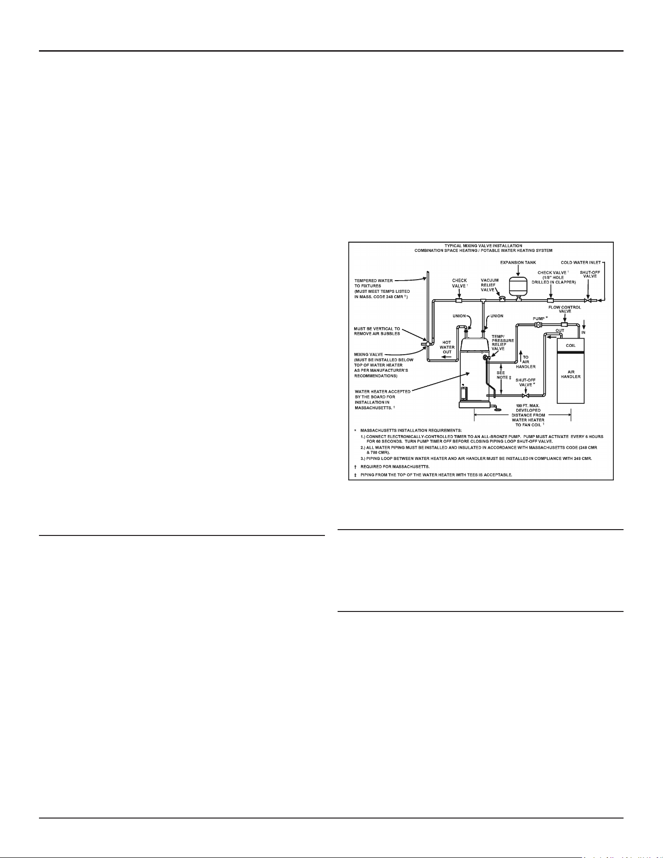
22 • Residential Gas Water Heaters
Installation Requirements
5. When installing multiple water heaters in the same gas supply system it
is recommended that individual positive lock-up gas pressure regulators
be installed at each unit.
All gas piping must comply with local codes and ordinances or with the
current editions
National Fuel Gas Code (ANSI Z223.1/ NFPA-54)
or the
Natural Gas and Propane Installation Code (CAN/CSA B149.1)
whichever
applies. Copper or brass tubing and fittings (except tin lined copper tubing)
shall not be used.
If the gas control valve is subjected to pressures exceeding 14 in wc (3.5
kPa), the damage to the gas control valve could result in a fire or explosion
from leaking gas.
If the main gas line Shut-off serving all gas water heaters is used, also turn
off the gas at each water heater. Leave all gas appliances shut off until the
water heater installation is complete.
A gas line of sufficient size must be run to the water heater. Consult the
current edition of
National Fuel Gas Code (ANSI Z223.1/NFPA 54)
or the
Natural Gas and Propane Installation Code (CAN/CSA B149.1)
and your gas
supplier concerning pipe size.
There must be:
• A readily accessible manual shut off valve in the gas supply line
serving the water heater, and
• A sediment trap ahead of the gas control valve to help prevent dirt
and foreign materials from entering the gas control valve.
• A ground joint union of proper size between the manual shut off
valve and control valve to permit servicing of the unit.
Be sure to check all the gas piping for leaks before lighting the water heater.
Use a soapy water solution, not a match or open flame. Rinse off soapy
solution and wipe dry.
Ensure that the gas line is properly supported to reduce the weight on the
gas train support.
SPACE HEATING AND POTABLE WATER SYSTEM
Your water heater is equipped with inlet/outlet connections for use in space
heating applications. See
Figure 13
. If this water heater is to be used to
supply both space heating and potable (drinking) water, the instructions
listed below must be followed:
• Be sure to follow the manual(s) shipped with the air handler or
other type heating system.
• This water heater cannot be used in space heating applications only.
• This water heater is not to be used as a replacement for an existing
boiler installation.
• Do not use with piping that has been treated with chromates, boiler
seal or other chemicals and do not add any chemicals to the water
heater piping
• If the space heating system requires water temperatures in excess of
120°F, a thermostatic point-of-use mixing valve must be installed per
the manufacturer’s instructions in the potable hot water supply to
limit the risk of scald injury.
• Pumps, valves, piping and fittings must be compatible with potable
water.
• A properly installed flow control valve is required to prevent
thermosiphoning. Thermosiphoning is the result of a continuous
flow of water through the air handler circuit during the off cycle.
Weeping (blow off) of the temperature and pressure relief valve (T &
P relief valve) or higher than normal water temperatures are the first
signs of thermosiphoning.
• The hot water line from the water heater should be vertical past
any mixing valve or supply line to the heating system to remove air
bubbles from the system Do not connect the water heater to any
system or components previously used with non-potable water
heating appliances when used to supply potable water.
Figure 13. Typical Mixing Valve and Space Heating Installation
CLOSED WATER SYSTEMS
Water supply systems may, because of code requirements or such
conditions as high line pressure, among others, have installed devices
such as pressure reducing valves, check valves, and back flow preventers.
Devices such as these cause the water system to be a closed system.
THERMAL EXPANSION
As water is heated, it expands (thermal expansion). In a closed system
the volume of water will grow when it is heated. As the volume of water
grows there will be a corresponding increase in water pressure due to
thermal expansion. Thermal expansion can cause premature tank failure
(leakage). This type of failure is not covered under the limited warranty.
Thermal expansion can also cause intermittent temperature-pressure relief
valve operation: water discharged from the valve due to excessive pressure
build up. This condition is not covered under the limited warranty. The
temperature-pressure relief valve is not intended for the constant relief
of thermal expansion.
A properly sized thermal expansion tank should be installed on all closed
systems to control the harmful effects of thermal expansion. Contact a
local plumbing service agency to have a thermal expansion tank installed.
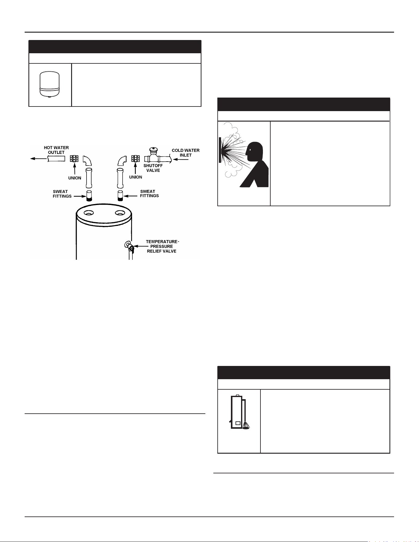
Installation Requirements
Residential Gas Water Heaters • 23
CAUTION
Property Damage Hazard
Avoid water heater damage from pressure fluctua�ons
in closed water systems.
• Fill tank with water before operating.
• Install thermal expansion tank if necessary.
• Do not apply heat to cold water inlet.
• Contact qualified installer or service agency.
Note: To protect against untimely corrosion of hot and cold water fittings,
it is strongly recommended that dielectric unions or couplings be
installed on this water heater when connected to copper pipe.
See
Figure 14
also.
Figure 14. Typical Water Piping Configuration
Figure 14
shows the typical attachment of the water piping to the water
heater. The water heater is equipped with 3/4 inch NPT water connections
for 50 gallon nominal capacity unit and 1 inch NPT water connections for
75 gallon nominal capacity unit.
Note: If using copper tubing, solder tubing to an adapter before attaching
the adapter to the water heater connections. Do not solder the
water lines directly to the water heater connections. It will harm
the dip tube and damage the tank, T & P Valve and Pipe Insulation
(if supplied)
Fit pipe insulation over the incoming cold water line and the hot water
line. Make sure that the insulation is against the top cover of the heater.
Fit T & P valve insulation over valve. Make sure that the insulation does
not interfere with the lever of the T & P valve.
Secure all insulation using tape.
TEMPERATURE-PRESSURE RELIEF VALVE
This water heater is provided with a properly rated/sized and certified
combination Temperature-Pressure Relief Valve (T&P relief valve) by the
manufacturer. The valve is certified by a nationally recognized testing
laboratory that maintains periodic inspection of production of listed
equipment of materials as meeting the requirements for
Relief Valves for
Hot Water Supply Systems, ANSI Z21.22 • CSA 4.4
, and the code requirements
of
ASME
.
If replaced, the new T&P valve must meet the requirements of local codes,
but not less than a combination Temperature-Pressure Relief Valve rated/
sized and certified as indicated in the above paragraph. The new valve
must be marked with a maximum set pressure not to exceed the marked
hydrostatic working pressure of the water heater (150 psi = 1,035 kPa) and
a discharge capacity not less than the water heater Btu/hr or kW input
rate as shown on the water heater’s model rating plate.
Note: In addition to the factory-installed Temperature-Pressure Relief
Valve on the water heater, each remote storage tank that may be
installed and piped to a water heating appliance must also have
its own properly sized, rated and approved Temperature-Pressure
Relief Valve installed.
Normal opera�on of the water heater can cause
it to become sufficiently over-heated and/or
over-pressurized that it can explode, resul�ng in
property damage, sever injury, or death.
To avoid this hazard, you must install a properly-
sized temperature-pressure relief valve in opening
provided.
• The temperature-pressure relief valve must
comply with ANSI Z21.22-CSA 4.4 and ASME
code.
• Do not plug, block, or cap the discharge line.
⚠
WARNING
Explosion Hazard
For safe operation of the water heater, the Temperature-Pressure Relief
Valve must not be removed from its designated opening nor plugged.
The Temperature-Pressure Relief Valve must be installed directly into the
fitting of the water heater designed for the relief valve. Install discharge
piping so that any discharge will exit the pipe within 6 inches (15.2 cm)
above an adequate floor drain, or external to the building. In cold climates
it is recommended that it be terminated at an adequate drain inside the
building. Be certain that no contact is made with any live electrical part.
The discharge opening must not be blocked or reduced in size under any
circumstances. Excessive length, over 30 feet (9.14 m), or use of more
than four elbows can cause restriction and reduce the discharge capacity
of the valve.
No valve or other obstruction is to be placed between the Temperature-
Pressure Relief Valve and the tank. Do not connect discharge piping directly
to the drain unless a 6” (15.2 cm) air gap is provided. To prevent bodily
injury, hazard to life, or property damage, the temperature-pressure relief
valve must be allowed to discharge water in adequate quantities should
circumstances demand. If the discharge pipe is not connected to a drain
or other suitable means, the water flow may cause property damage.
Property Damage Hazard
While the water heater is in rou�ne opera�on, it can
release hot water from the temperature-pressure relief
valve discharge pipe in quan��es that could cause
damage to the surroundings.
Locate the water heater near an adequate drain and
in an area where water from the temperature-pres-
sure relief valve discharge pipe will not result in
damage to the area or the lower floors of the
structure.
⚠
CAUTION
T&P VALVE DISCHARGE PIPE REQUIREMENTS:
• Shall not be smaller in size than the outlet pipe size of the valve, or
have any reducing couplings or other restrictions.
• Shall not be plugged or blocked.
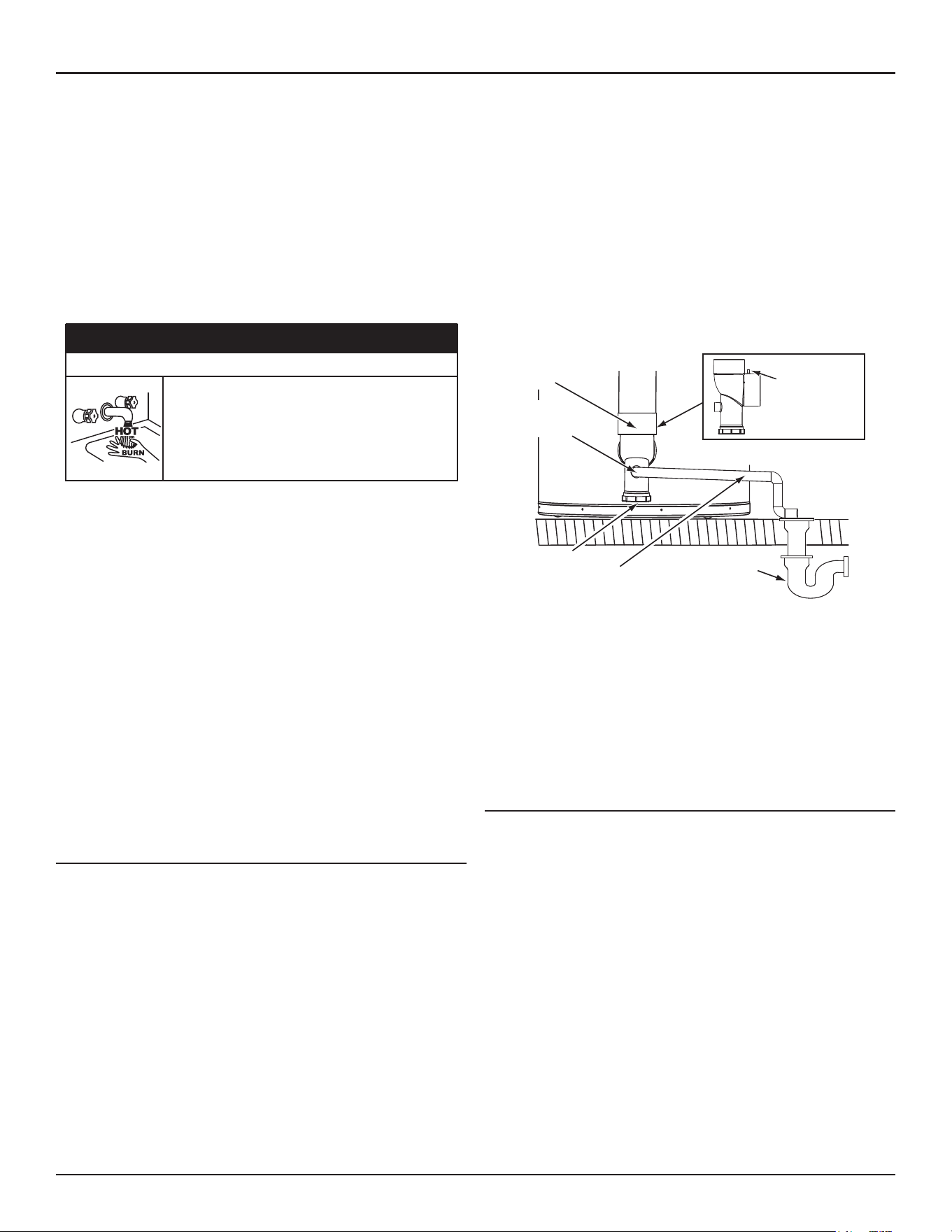
24 • Residential Gas Water Heaters
Installation Requirements
• Shall not be exposed to freezing temperatures.
• Shall be of material listed for hot water distribution.
• Shall be installed so as to allow complete drainage of both the
Temperature-Pressure Relief Valve and the discharge pipe.
• Must terminate a maximum of six inches (15.2 cm) above a floor
drain or external to the building. In cold climates, it is recommended
that the discharge pipe be terminated at an adequate drain inside
the building.
• Shall not have any valve or other obstruction between the
temperature-pressure relief valve and the drain.
⚠
DANGER
Burn Hazard
The discharge water from the temperature-pressure
relief valve is hot enough to cause burns.
Keep clear of the temperature-pressure relief valve
discharge outlet.
The Temperature-Pressure Relief Valve must be manually operated at
least twice a year. Caution should be taken to ensure that (1) no one is
in front of or around the outlet of the Temperature-Pressure Relief Valve
discharge line, and (2) the water manually discharged will not cause any
bodily injury or property damage because the water may be extremely
hot. If after manually operating the valve, it fails to completely reset and
continues to release water, immediately close the cold water inlet to the
water heater, follow the draining instructions in this manual, and replace
the Temperature-Pressure Relief Valve with a properly rated/sized new one.
Note: The purpose of a Temperature-Pressure Relief Valve is to prevent
excessive temperatures and pressures in the storage tank. The T&P
valve is not intended for the constant relief of thermal expansion.
A properly sized thermal expansion tank must be installed on all
closed systems to control thermal expansion. See
Closed Water
Systems
(page 22) and
Thermal Expansion
(page 22).
If you do not understand these instructions or have any questions regarding
the Temperature-Pressure Relief Valve call the toll free number found on
the warranty sheet provided with the water heater for technical assistance.
CONDENSATE PIPING
The water heaters covered in this manual are condensing appliances
and require a building drain to be located in close proximity to allow the
condensate to drain safely.
Condensate drains from the water heater at the exhaust elbow located at
the bottom. The field-installed condensate drain line must not be elevated
above the condensate drain connection on the condensate trap. See
Figure
15
. If the condensate does not drain properly it will build up in the exhaust
(vent) elbow. This will restrict the flow of flue gases and cause the Blocked
Exhaust pressure switch to open its contacts. The control system monitors
all pressure switches, if the Blocked Exhaust Switch contacts are open the
control system will lock out and disable heating operation. The “Blocked
Exhaust” Fault message will be displayed on the control system’s LCD.
The Condensate Clean-out Cap must be on and tight when unit is in
operation.
Note: If the “Blocked Exhaust“ Fault message is ever displayed on the
control system LCD, check the condensate drain first and ensure
it is not blocked.
EXHAUST (VENT)
ELBOW
THIS SIDE VIEW
OF EXHAUST
ELBOW AND
ARROW INDICATE
THE LOCATION OF
THE PRESSURE
PORT
BUILDING
DRAIN
CONDENSATE
CLEANOUT CAP
CONDENSATE DRAIN
LINE - FIELD INSTALLED
CONDENSATE
DRAIN LINE
CONNECTION
Figure 15. Condensate Drain Configuration
DO NOT
remove the factory-installed exhaust/condensate elbow for
any reason. See
Figure 15
. The water heater’s vent pipe is under a slight
positive pressure while unit is in operation. The water trap inside of the
exhaust/condensate elbow prevents flue gases from escaping into the
installed space.
Do not install any external condensate trap. The exhaust elbow assembly
has an internal condensate trap.
CONDENSATE PH LEVEL
The condensate drains from the water heater’s covered in this manual have
pH levels between 4.3 and 5.0. Install a commercially available neutralizing
kit if required by local codes.
Note: Lower pH levels are acidic. Do not connect a metal drain line, such
as copper, to the water heater for this reason. See
Condensate Drain
Installation
(page 36) .
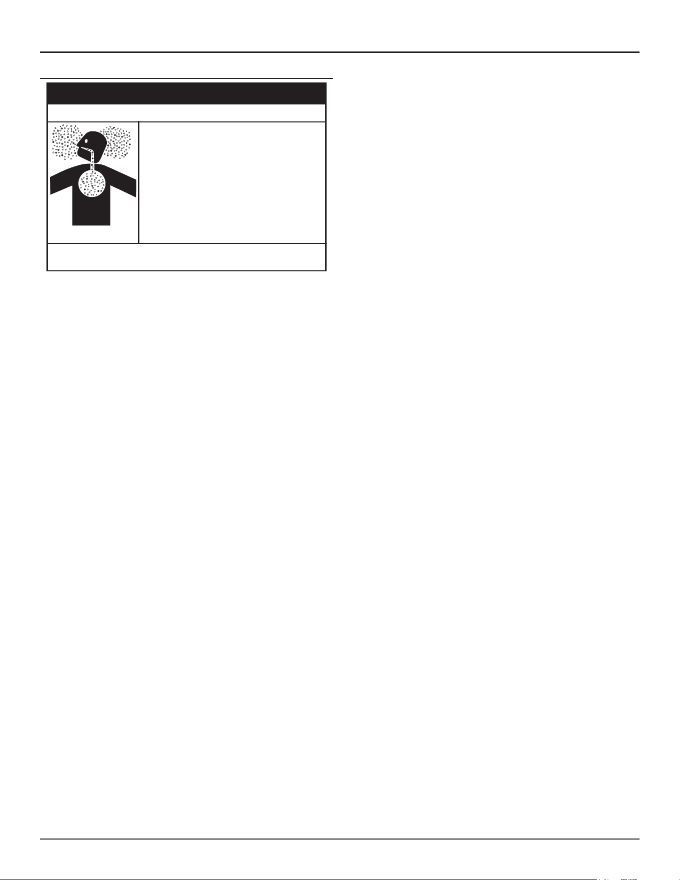
Installation Requirements
Residential Gas Water Heaters • 25
HIGH ALTITUDE INSTALLATIONS
• Special considera�ons must be taken with
installa�ons above 10,100 (3,078 meters).
• Please contact an A. O. Smith qualified
service agent to obtain the proper setup
and instruc�ons before ligh�ng.
• Failure to implement the proper setup will
result in improper and inefficient opera�on
of the appliance, resul�ng in produc�on of
increased levels of carbon monoxide gas in
excess of the safe limits which could result
in serious personal injury or death.
Breathing carbon monoxide can cause brain damage or death. Always read
and understand instruc�on manual.
⚠
WARNING
Breathing Hazard - Carbon Monoxide Gas
This high efficiency water heater is certified for use without modification
for an altitude of 10,100 feet (3,078 m). Consult the factory for installation
at altitudes over 10,100 feet (3,078 m).
Some gas utility companies derate their gas for altitude. Call the local gas
or utility company to verify the BTU content.
Due to the input rate reduction at high altitudes, the output rating of the
water heater is also reduced and should be compensated for in the sizing
of the equipment for applications.

26 • Residential Gas Water Heaters
Installation Requirements
MASSACHUSETTS INSTALLATION REQUIREMENTS
For all side wall terminated, horizontally vented power vent, direct vent,
and power direct vent gas fueled water heaters installed in every dwelling,
building or structure used in whole or in part for residential purposes,
including those owned or operated by the Commonwealth and where the
side wall exhaust vent termination is less than seven (7) feet above finished
grade in the area of the venting, including but not limited to decks and
porches, the following requirements should be satisfied:
INSTALLATION OF CARBON MONOXIDE DETECTORS At the time of
installation of the side wall horizontal vented gas fueled equipment, the
installing plumber or gas-fitter should observe that a hard wired carbon
monoxide detector with an alarm and battery back-up is installed on the
floor level where the gas equipment is to be installed. In addition, the
installing plumber or gas-fitter should observe that a battery operated or
hard wired carbon monoxide detector with an alarm is installed on each
additional level of the dwelling, building or structure served by the sidewall
horizontal vented gas fueled equipment. It should be the responsibility
of the property owner to secure the services of qualified licensed
professionals for the installation of hard wired carbon monoxide detectors.
In the event that the side wall horizontally vented gas fueled equipment
is installed in a crawl space or an attic, the hard wired carbon monoxide
detector with alarm and battery back-up may be installed on the next
adjacent floor level.
In the event that the requirements of this subdivision can not be met at
the time of completion of installation, the owner should have a period
of thirty (30) days to comply with the above requirements provided that
during said thirty (30) day period, a battery operated carbon monoxide
detector with an alarm should be installed.
APPROVED CARBON MONOXIDE DETECTORS Each carbon monoxide
detector as required in accordance with the above provisions should
comply with
NFPA 720
and be
ANSI/UL 2034
listed and
CSA
certified.
SIGNAGE A metal or plastic identification plate should be permanently
mounted to the exterior of the building at a minimum height of eight (8)
feet above grade directly in line with the exhaust vent terminal for the
horizontally vented gas fueled heating appliance or equipment. The sign
should read, in print size no less than one-half (1/2) inch in size,
GAS VENT
DIRECTLY BELOW. KEEP CLEAR OF ALL OBSTRUCTIONS
.
INSPECTION The state or local gas inspector of the side wall horizontally
vented gas fueled equipment should not approve the installation unless,
upon inspection, the inspector observes carbon monoxide detectors and
signage installed in accordance with the provisions of 248 CMR 5.08(2)
(a) 1 through 4.
EXEMPTIONS: The following equipment is exempt from 248 CMR 5.08(2)
(a)1 through 4:
1. The equipment listed in Chapter 10 entitled Equipment Not Required
To Be Vented in the most current edition of NFPA 54 as adopted by
the Board; and
2. Product Approved side wall horizontally vented gas fueled equipment
installed in a room or structure separate from the dwelling, building,
or structure used in whole or in part for residential purposes.
MANUFACTURER REQUIREMENTS - GAS EQUIPMENT VENTING SYSTEM
PROVIDED When the manufacturer of Product Approved side wall
horizontally vented gas equipment provides a venting system design or
venting system components with the equipment, the instructions provided
by the manufacturer for installation of the equipment and the venting
system should include:
1. Detailed instructions for the installation of the venting system design
or the venting system components; and
2. A complete parts list for the venting system design or venting system.
MANUFACTURER REQUIREMENTS - GAS EQUIPMENT VENTING SYSTEM
NOT PROVIDED When the manufacturer of a Product Approved side wall
horizontally vented gas fueled equipment does not provide the parts for
venting the flue gases, but identifies special venting systems, the following
requirements should be satisfied by the manufacturer:
1. The referenced special venting system instructions should be included
with the appliance or equipment installation instructions; and
2. The special venting systems should be Product Approved by the Board,
and the instructions for that system should include a parts list and
detailed installation instructions.
A copy of all installation instructions for all Product Approved
side wall horizontally vented gas fueled equipment, all venting
instructions, all parts lists for venting instructions, and/or all
venting design instructions should remain with the appliance or
equipment at the completion of the installation.
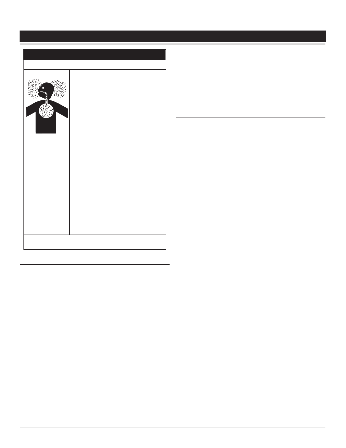
Residential Gas Water Heaters • 27
VENTING INSTALLATION
Breathing carbon monoxide can cause brain damage or death. Always
read and understand instruc�on manual.
⚠
WARNING
Breathing Hazard - Carbon Monoxide Gas
• Install vent system in accordance with codes.
•
Do not operate water heater if any part has been
exposed to flooding or water damage.
• High altitude models should be installed at
elevations above 5,300 feet (1,615 m). For
operation above 10,100 feet (3,079 m), a high
altitude orifice must be installed.
• Do not operate if soot buildup is present.
• Do not obstruct water heater air intake with
insulating jacket.
• Do not place chemical vapor emitting products
near water heater.
•
Gas and carbon monoxide detectors are available.
• No vent damper installation is compatible with
this power vented water heater.
•
Do NOT elevate any portion of the field supplied
drain line beyond the 1/2” adapter above the
adapter. This must be true for the entire length
of the drain line including the exit into an
appropriate drain.
•
Condensate lines must be free and clear of debris
and must not allow back flow through the hose.
The condensate lines must be able to flow freely
to an appropriate drain.
• Do not allow condensate lines to become
crimped closed.
•
Analyze the entire vent system to make sure that
condensate will not become trapped in a section
of vent pipe and therefore reduce the open cross
sectional area of the vent.
VENT INSTALLATION CONSIDERATIONS
This water heater can be vented using room air for intake combustion
air, or direct vented so that all intake air for combustion comes from the
outside through a sealed pipe.
The water heater venting may be installed in four separate orientations
depending on the requirements of the building and the water heater.
The installer must decide which method is most appropriate for each
installation. These orientations are:
1. Vertical Termination - vertical vent termination through unenclosed
or enclosed areas with roof penetration. See
Vertical Vent Terminal
Installation
(page 30).
2. Through-the-Wall Termination - horizontal vent termination directly
through an outside wall. See
Figure 16
(page 29).
3. Horizontal Direct Vent - using Through-the-Wall Termination to exhaust
flue products and piping to bring combustion air to the water heater
from the outside. See
Figure 17
(page 29),
Figure 27
(page 34) and
Figure 28
(page 34).
4. Vertical Direct Vent - using a vertical vent termination to exhaust flue
products and piping to bring combustion air to the water heater from
outside. See
Figure 25
(page 34) and
Figure 26
(page 34).
In cold climates any water vapor remaining in the flue gases will condense
into a cloud of vapor at the point where the vent system exits the
building. Special consideration is recommended, before locating the vent
termination near walkways, windows and building entrances.
Direct venting into dead spaces such as alleys, atriums, and inside corners
can cause recirculation of flue gases. Recirculation of flue gases will cause
sooting, and icing of the combustion air intake during severe cold weather.
To prevent the recirculation of flue gases, maintain as much distance as
possible between the combustion air intake and the exhaust vent terminal.
See
Figure 23
(page 32) and
Figure 24
(page 33).
VENT/INTAKE MATERIAL
Approved vent and intake air pipe materials that may be used in the
United States:
PVC pipe materials:
• DWV ASTM-D2665 or CSA B181.2
• Schedule 40, 80, 120 ASTM-D1785 or CSA B137.3
• SDR Series ASTM-2241 or CSA B137.3
CPVC pipe materials:
• CPVC 41 ASTM-D2846 or CSA B137.6
• Schedule 40, 80 ASTM-F441 or CSA B137.6
• SDR Series ASTM-F442
Polypropylene - See
Polypropylene Installations
(page 28).
• M & G Duravent PolyPro vent system
• Centrotherm InnoFlue vent system
Approved vent pipe materials that must be used in Canada:
• ULC S636 PVC / CPVC
• ULC S636 Polypropylene - See
Polypropylene Installations
(page
28).
Approved intake air pipe materials that must be used in Canada:
PVC pipe materials:
• DWV ASTM-D2665 or CSA B181.2
• Schedule 40, 80, 120 ASTM-D1785 or CSA B137.3
• SDR Series ASTM-D2241 or CSA B137.3
CPVC pipe materials:
• CPVC 41 ASTM-D2846 or CSA B137.6
• Schedule 40, 80 ASTM-F441 or CSA B137.6
• SDR Series ASTM-F442
Polypropylene - See
Polypropylene Installations
(page 28).
• M & G Duravent PolyPro vent system
• Centrotherm InnoFlue vent system
Where applicable, the installation of the venting system should be done in
accordance with the venting system manufacturer’s instructions.
Note: The use of cellular core PVC (ASTM F891), cellular core CPVC,
or Radel
®
(polyphenolsulfone) in non-metallic venting systems
is prohibited. Covering non-metallic vent pipe and fittings with
thermal insulation is prohibited.
If the water heater is being installed as a replacement for an existing
power vented heater in pre-existing venting, a thorough inspection of
existing venting system must be performed prior to any installation work.
Verify that correct material as detailed above has been used, and that the
minimum or maximum vent lengths and terminal location as detailed in
this manual have been met. Carefully inspect the entire venting system
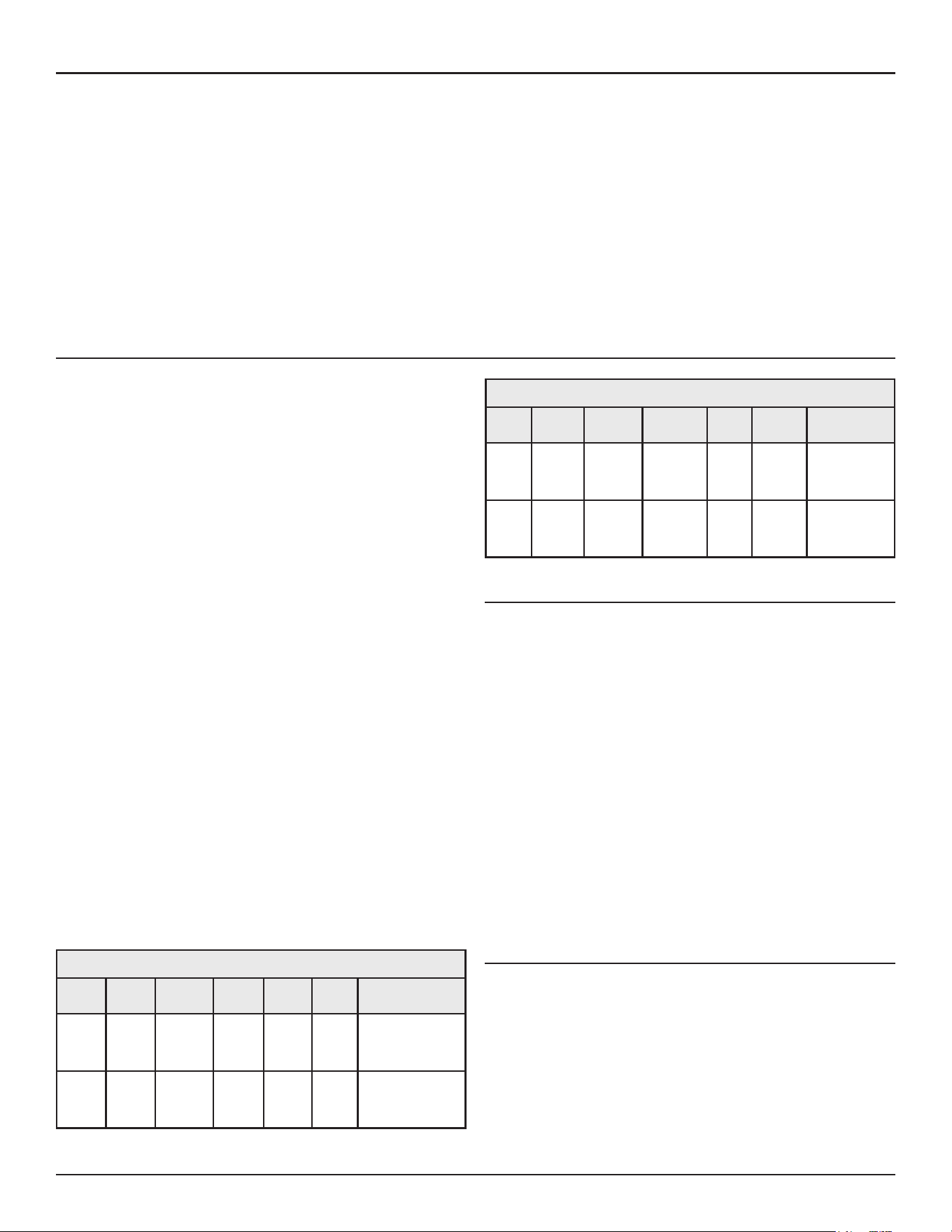
28 • Residential Gas Water Heaters
Venting Installation
for any signs of cracks or fractures, particularly at joints between elbows
and other fittings and straight runs of vent pipe. Check system for signs
of sagging or other stresses in joints as a result of misalignment of any
components in the system. If any of these conditions are found, they must
be corrected in accordance with the venting instructions in this manual
before completing installation and putting the water heater into service.
Note: For water heaters in locations with high ambient temperatures
above 100°F (38°C) it is recommended that CPVC or Polypropylene
pipe and fittings be used.
All vent (exhaust) pipes must be pitched a minimum of a 1/4” per foot
back to the water heater to allow drainage of condensation.
Never operate the water heater unless it is vented to the outdoors.
The instructions in this section of the manual must be followed to avoid
choked combustion or recirculation of flue gases. Such conditions cause
sooting of the combustion chamber, burners and flue, and creates a risk
of asphyxiation.
For direct vent application where combustion air might be supplied from
cold outdoor ambient temperatures through the fresh air intake piping
system, it is recommended that a back-flow preventer and / or a drain
tee be installed in the air intake before proceeding with installation of
the rest of the fresh air intake piping. See
Direct Vent Air Intake Moisture
Protection
(page 30)
or call the toll free number found on the warranty
sheet provided with the water heater for technical assistance.
POLYPROPYLENE INSTALLATIONS
The water heater has been approved to be installed with Polypropylene
vent material as shown in
Table 5
and
Table 6
. The approved application
of single wall, non-flexible, non-concentric Polypropylene vent material
is offered by two specific manufacturers (Centrotherm ECO Systems
and DuraVent Polypropylene). These listed products must be installed
by following the vent manufacturer’s instructions. See
Table 7
on (page
29) to determine the maximum pipe length and number of elbows that
can be used.
Insulation should not be used on Polypropylene venting materials. The
use of insulation will cause increased vent wall temperatures, which could
result in vent pipe failure.
Use only the adapters and vent system listed in tables below. DO
NOT
mix
vent systems of different types or manufacturers. Failure to comply could
result in severe personal injury, death, or substantial property damage.
Installations must comply with applicable national, state, and local codes.
For Canadian installation, Polypropylene vent must be listed as a
ULC-S636
approved system. If Polypropylene vent is not required by your local code,
you may use either PVC or CPVC pipes for your water heater that allows
non-metallic venting material installations.
Polypropylene vent systems do not use cement to connect the pipe and
elbow sections but use a push together gasket seal method. Do not attempt
to connect Polypropylene with sealant cement. All vent connections
MUST
be secured by the vent manufacturer’s joint connector. The installer must
use a specific vent starter adapter at the flue connection. The adapter is
supplied by the vent manufacturer to adapt to its vent system.
In order to be in full compliance with
UL 1738
or
ULC-S636
and to meet the
requirements of the water heater manufacturer, you must use the metal
joint connector rings, available from the Polypropylene vent manufacturer,
to stiffen the joints of 2”, and 3” diameter pipes.
Table 5. M & G Duravent PolyPro
Nominal
Pipe
Diameter
Flue
Outlet
Adapter
Adapter
Connector
Ring
Connec-
tor
90
Degree
Elbow
Vent
Material
Terminal(s)
2” 2PPS-AD PPS-PAC 2PPS-LB 2PPS-E90 2PPS
2PPS & 2PPS-BG for
Exhaust;
2PPS-E90 & 2PPS-BG
for Intake (Direct Vent
only)
3” 3PPS-AD PPS-PAC 3PPS-LB 3PPS-E90 3PPS
3PPS & 3PPS-BG for
Exhaust;
3PPS-E90 & 3PPS-BG
for Intake (Direct Vent
only)
Table 6. Centrotherm InnoFlue SW
Nominal
Pipe
Dia.
Flue
Outlet
Adapter
Adapter
Connector
Ring
Connector
90
Degree
Elbow
Vent
Material
Terminal(s)
2”
ISAGL
0202
IAFC02 IANS02
IS-
ELL0287
ISVL02
ISVL02 & IASPP02
for Exhaust;
ISELL0287 &
IASPP02 for Intake
(Direct Vent only)
3”
ISAGL
0303
IAFC03 IANS03
IS-
ELL0387
ISVL03
ISVL03 & IASPP03
for Exhaust;
ISELL0387 &
IASPP03 for Intake
(Direct Vent only)
VENT PIPE TERMINATION
The first step is to determine where the vent pipe will terminate. The vent
may terminate through a sidewall as shown in
Figure 16
(page 29),
Figure
18
(page 30), and
Figure 19
(page 30)
or through the roof as shown
in
Figure 20
(page 31),
Figure 21
(page 31) and
Figure 22
(page 31).
The vent system must terminate so that proper clearances are maintained
as cited in local codes or the current edition of the
National Fuel Gas
Code
,
(ANSI Z223.1, 12.9.1 through 12.9.4)
or the
Natural Gas and Propane
Installation Code (CAN/CSA-B149.1)
. See
Figure 23
(page 32) and
Figure
24
(page 33).
Plan the vent system layout so that proper clearances are maintained from
plumbing and wiring.
Vent pipes serving power vented water heaters are classified by building
codes as vent connectors. Required clearances from combustible materials
must be provided in accordance with information in this manual under
Venting Installation
(page 27)
and
Installation Requirements
(page 20),
and with the
National Fuel Gas Code
and local codes.
PLANNING THE VENT SYSTEM
Plan the route of the vent system from the exhaust elbow to the planned
location of the vent terminal.
Do not locate the vent termination over public walkways or a public area
where condensate or vapor can cause a nuisance or ice hazard.
Water heaters covered by these instructions are Category IV appliances.
1. Layout total vent system to use a minimum of vent pipe and elbows.
2. This water heater is capable of venting flue gases in equivalent length
of pipe as listed in
Table 7
.
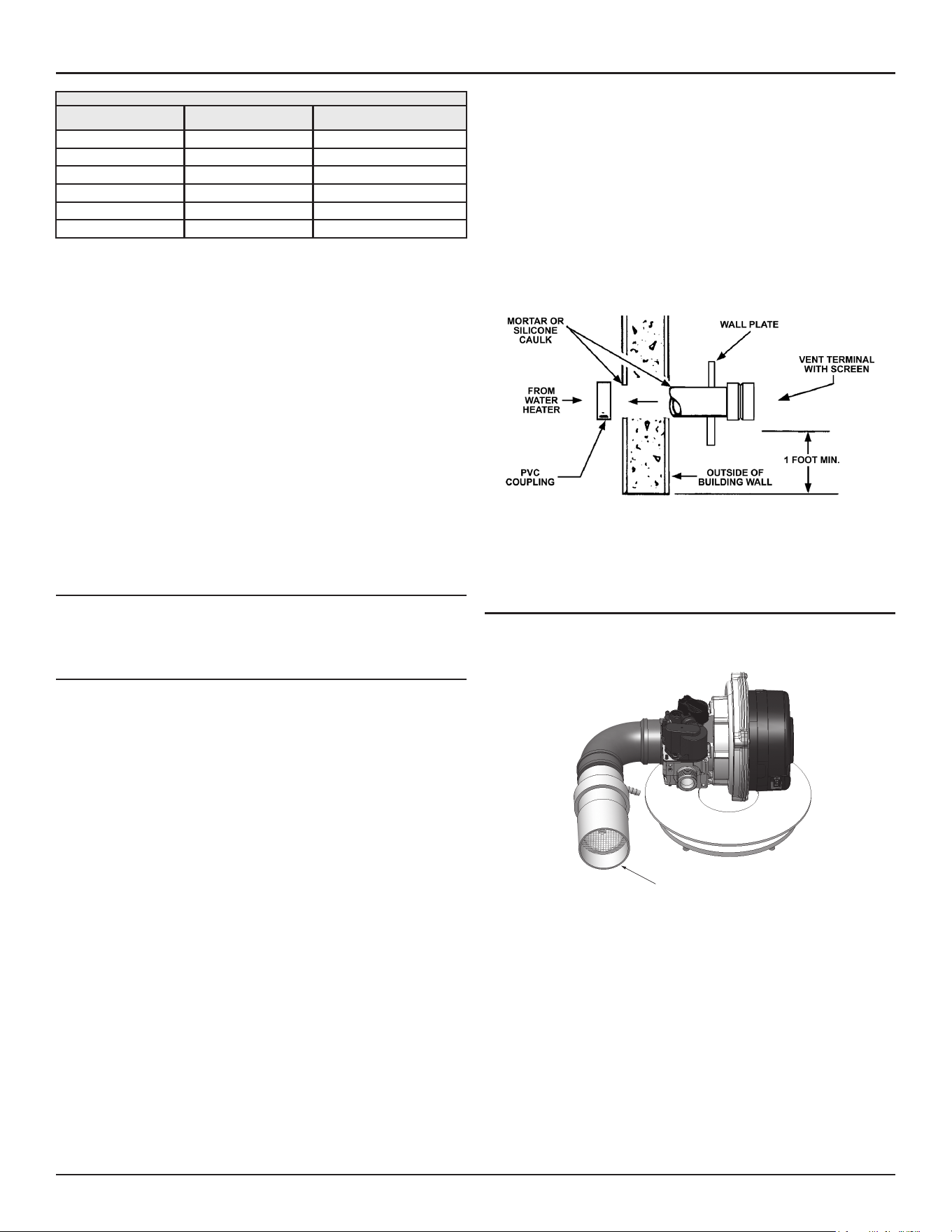
Venting Installation
Residential Gas Water Heaters • 29
Table 7. Max Pipe Lengths Per Number of 90° Elbows
Number of
90° Elbows
2” Maximum
Pipe - ft.. (m)
3” Maximum
Pipe - ft.. (m)
1 60 (18.2) 130 (39.6)
2 55 (16.8) 125 (38.1)
3 50 (15.2) 120 (36.6)
4 45 (13.7) 115 (35.0)
5 40 (12.1) 110 (33.5)
6 35 (10.7) 105 (32.0)
The minimum vent length for each of the pipe size is one 90° elbow plus 2’
and 7’ (0.61 m and 2.1 m) of straight pipe for air intake and exhaust vent
respectively and the appropriate termination.
Note: The equivalent length of pipe listed above are exclusive of the
termination. That is, the termination, with an installed screen,
is assumed to be in the system and the remainder of the system
must not exceed the lengths and number of elbows shown in
Table
7
(page 29).
If using 2” inch vent pipe: A 2” diameter vent pipe must be inserted and
fastened to the exhaust elbow assembly.
If using 3” inch vent pipe: Two inches (5.1 cm) of 2” diameter pipe must be
inserted and fastened to the exhaust elbow assembly before adding a 2’ x
3” reducer to acquire the desired pipe diameter. A 3” coupling (supplied
locally-a schedule 40 DWV) vent terminal must be obtained. A 3” diameter
screen is supplied in the vent kit.
INSTALLATION OF HORIZONTAL THROUGH THE WALL VENT SYS-
TEM
If you are installing your system so that it vents through roof, please see
Vertical Vent Terminal Installation
(page 30).
VENT TERMINAL INSTALLATION, SIDEWALL
1. Install the vent terminal by using the cover plate as a template to
mark the hole for the vent pipe to pass through the wall.
BEWARE OF
CONCEALED WIRING AND PIPING INSIDE THE WALL
.
2. If the Vent Terminal is being installed on the outside of a finished wall, it
may be easier to mark both the inside and outside wall. Align the holes
by drilling a hole through the center of the template from the inside
through to the outside. The template can now be positioned on the
outside wall using the drilled hole as a centering point for the template.
A. MASONRY SIDE WALLS
Chisel an opening approximately one half inch (1.3 cm) larger
than the marked circle.
B. WOODEN SIDE WALLS
Drill a pilot hole approximately one quarter inch (0.64 cm)
outside of the marked circle. This pilot hole is used as a starting
point for a saws-all or sabre saw blade. Cut around the marked
circle staying approximately one quarter inch (0.64 cm) outside
of the line. (This will allow the vent to easily slide through
the opening. The resulting gap will be covered up by the Vent
Terminal wall plate.) Repeat this step on inside wall if necessary.
Cut a length of pipe about 3.5 inches (8.9 cm) longer than the wall
thickness at the opening. Glue the vent terminal to this section
of pipe. Slide the wall plate over the pipe to stop against the vent
terminal. Place a bead of caulking (not supplied) around the gap
between the pipe and cover plate. Apply enough to fill some of
the gap between the pipe and wall. Place some of the caulking on
the back of the plate to hold it against the wall after installation.
If the vent pipe is installed up to the wall, with a coupling on the
end against the wall opening, the pipe with the vent terminal can
be prepared for gluing before inserting through the wall. Slide
the pipe through the wall and insert into the coupling on the
other side of the wall, making sure that the vent terminal ends
up pointed in the correct position. See
Figure 16
.
Figure 16. Sidewall Vent Termination
DIRECT VENT TERMINAL INSTALLATION
The air intake provided on the unit contains an air intake screen to prevent
large particles from entering the unit.
Air Intake Screen
(Remove For Direct Vent)
Figure 17. Blower Air Inlet Assembly
Note: When the unit is to be set up as a direct vent, the air intake screen
must be removed. The air intake pipe may then be glued to the air
intake provided on the unit. See
Figure 17
(page 29)
.
This unit consists of two terminals - an air intake terminal and an exhaust
vent terminal. The air intake terminal is a 2” 90° PVC elbow with an air
intake screen and the exhaust vent terminal is a 2” straight PVC coupling
with a mesh wire screen.
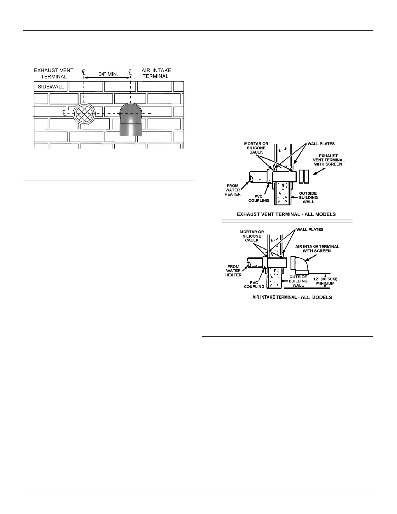
30 • Residential Gas Water Heaters
Venting Installation
Note: To prevent exhausting products from circulating to the air intake in
windy/cold areas, the maximum practical distance between these
two terminals is recommended.
Figure 18. Sidewall Intake/Exhaust Separation Clearance
DIRECT VENT AIR INTAKE MOISTURE PROTECTION
The air intake piping in a direct vent system will normally not have any
moisture accumulation in it. However, in certain cases, moisture may
build up and needs to be drained. Typical situations include, but are not
limited to:
• Cold outdoor temperature, particularly if the air inlet is short,
• Heater being used mostly for space heating and
• Air inlet pipe has vertical rise near the heater.
Installations with any of these conditions are required to provide a moisture
drain with a trap that flows to a waste drain. See
Figure 25
(page 34),
Figure 26
(page 34),
Figure 27
(page 34) and
Figure 28
(page 34).
A horizontal section of the air inlet pipe, near the heater should include
a 2” by 2” by 1/2” tee and a hose barb fitting to drain the water. The tee
should be as close to the heater as is practical. The drain tubing in any
installation should have a loop trap and flow to an appropriate waste drain.
The air intake drain line must be entirely separate from the exhaust vent
outlet condensate line.
INSTALLATION SEQUENCE
1. After the points of termination have been determined,
use the cover plates as templates to mark the holes for
the vent pipes to be inserted through the wall.
BEWARE OF CONCEALED
WIRING AND PIPING INSIDE OF WALL
. If the vent terminals are being
installed on the outside of a finished wall, it may be easier to mark both
the inside and outside wall. Align the holes by drilling a hole through
the center of the template from the inside through to the outside. The
template can now be positioned on the outside wall using the drilled
holes as a centering point for the template.
A.
MASONRY SIDE WALLS
Chisel an opening approximately 1/2” (1.3
cm) larger than the marked circle.
B.
WOODEN SIDE WALLS
Drill a pilot hole approximately one quarter
inch outside of the marked circle. This pilot hole is used as a
starting point for a saws-all or sabre saw blade. Cut around the
marked circle staying approximately one quarter inch outside of
the line. (This will allow the vent pipe to easily slide through the
opening. The resulting gap will be covered by the vent terminal
cover plates.) Repeat this step on the inside wall if necessary.
2. Cut a length of pipe about 3.5” (8.9 cm) longer than the wall thickness
at the opening.
3. Glue the air intake terminal to the section of the pipe.
4. Slide the wall plate over pipe to stop against air intake terminal.
5. Place a bead of caulking (not supplied) around the gap between the
pipe and the wall. Place some of the caulking on the back of the plate
to hold it against the wall after installation.
6. If the air intake pipe is installed up to the wall, with a coupling on the
end against the wall opening, the pipe with the air intake terminal can
be prepared for gluing before inserting through the wall. Slide the pipe
through the wall and insert into coupling on the other side of the wall,
making sure that the air intake terminal ends up pointed in the correct
position (
Figure 18
and
Figure 19
).
Figure 19. Side-Wall Intake/Exhaust Termination Installation
VERTICAL VENT TERMINAL INSTALLATION
WHEN TERMINATING THROUGH A ROOF, THE FOLLOWING SPECIFICATIONS
PERTAINING TO TERMINAL LOCATION MUST BE FOLLOWED.
1. Proper support must be provided for all pipe protruding through the
roof.
2. The vertical roof terminations should be sealed with a plumbing roof
boot or equivalent flashing.
3. The air intake termination and the exhaust vent termination must
penetrate the same side of roof.
4. The center line of the air intake termination and the center line of the
exhaust vent termination must be no closer than 24” (61 cm). See
Figure
20
(page 31) and
Figure 21
(page 31).
FLAT ROOF INSTALLATION
On flat roof installations the air intake and the exhaust vent terminations
must be a minimum of 24 inches (60 cm) above any parapet, vertical wall
or structure within 10 feet (3 m) horizontally. See
Figure 22
.
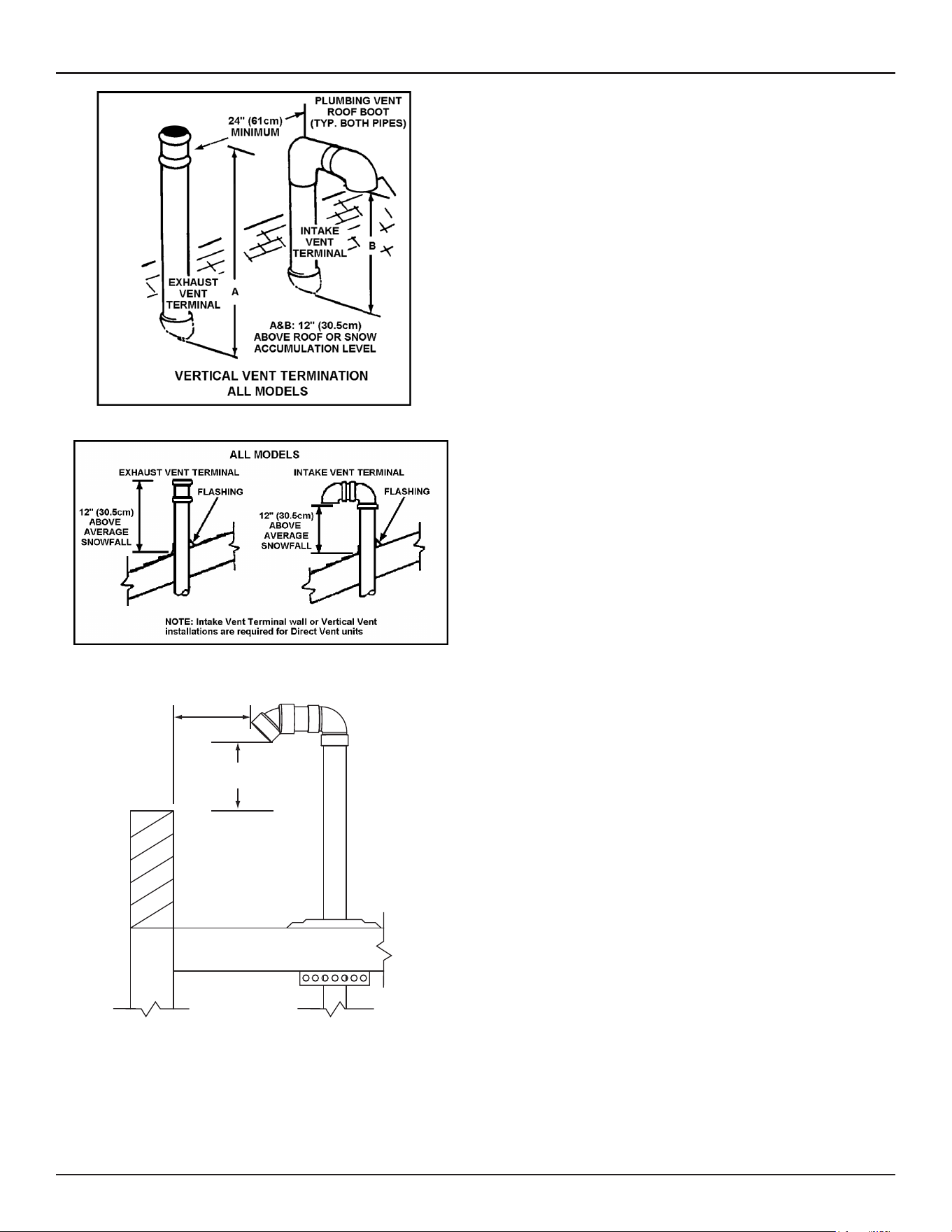
Venting Installation
Residential Gas Water Heaters • 31
Figure 20. Pitched Roof Separation Clearances
Figure 21. Pitched Roof Snow Clearances
INTAKE AIR AND/OR VENT
TERMINATION(S) MUST BE A
MINIMUM OF 24 INCHES (60 cm)
ABOVE ANY PARAPET, VERTICAL
WALL OR STRUCTURE WITHIN
10 FEET (3 m) HORIZONTALLY.
VERTICAL TERMINATION(S) FLAT ROOF CLEARANCE
INTAKE AIR AND/OR VENT (EXHAUST)
24 INCHES (60 cm)
MINIMUM HEIGHT ABOVE
IF LESS THAN
10 FEET (3 m)
Figure 22. Flat Roof Clearances
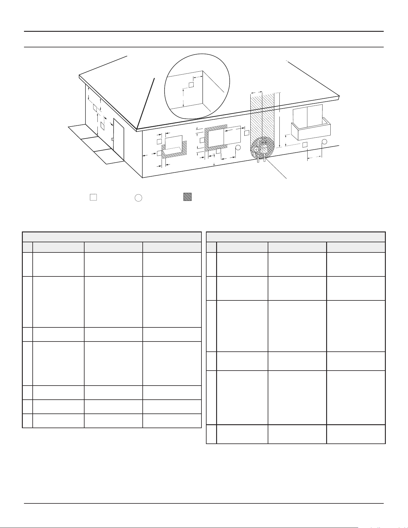
32 • Residential Gas Water Heaters
Venting Installation
SIDEWALL TERMINATION DIRECT VENT CLEARANCES
Fixed
Closed
Operable
Fixed
closed
Operable
B
V
V
V
V
V
V
V
V
C
B
B
X
A
M
K
Regulator vent outlet
In the event no
regulator is present,
H and I can be
disregarded
.
V
Legend:
= Vent terminal
X
= Air supply inlet
= Area where terminal is not permitted
B
B
J
F
X
B
L
E
D
Inside
corner detail
V
A
G
H
15 ft
I
Figure 23. Direct Vent Using Outside Air
Vent terminal clearances for “Power Vent” installations. Power Vent configurations use room air for combustion.
Termination Clearances for Sidewall Direct Vent
Type of Clearance
Canadian Installations
1
US Installations
2
A
Clearance above
grade, veranda,
porch, deck or
balcony
12 inches (30 cm) 12 inches (30 cm)
B
Clearance to window
or door that may be
opened
• 6 in (15 cm) for appli-
ances ≤ 10,000 Btuh
(3 kW)
• 12 in (30 cm) for ap-
pliances > 10,000 Btuh
(3 kW) and ≤ 100,000
Btuh (30 kW),
• 36 in (91 cm) for appli-
ances > 100,000 Btuh
(30 kW)
• 4 feet (1.2 m) below or
to side of opening;
• 1 foot (30 cm) above
opening
C
Clearance to perma-
nently closed window
6 inches (15 cm)* 6 inches (15 cm)*
D
Vertical clearance
to ventilated soffit
located above the
terminal within a
horizontal distance of
2 feet (61 cm) from
the center line of the
terminal
12 inches (30 cm) 12 inches (30 cm)
E
Clearance to unventi-
lated soffit
12 inches (30 cm) 12 inches (30 cm)
F
Clearance to outside
corner
2 feet (60 cm)* 2 feet (60 cm)*
G
Clearance to inside
corner
18 inches (45 cm)* 18 inches (45 cm)*
Termination Clearances for Sidewall Direct Vent
Type of Clearance
Canadian Installations
1
US Installations
2
H
Clearance to each
side of center line ex-
tended above meter/
regulator assembly
3 ft. (91 cm) within a
height 15 ft. (4.6 m)
Clearance in accordance
with local installation
codes and the require-
ments of the gas supplier
I
Clearance to service
regulator vent outlet
3 ft. (1.83 m)
Clearance in accordance
with local installation
codes and the require-
ments of the gas supplier
J
Clearance to a non
mechanical air supply
inlet into building or
combustion air inlet
to any other appli-
ance
• 6 in (15 cm) for appli-
ances ≤ 10,000 Btuh
(3 kW)
• 12 in (30 cm) for ap-
pliances > 10,000 Btuh
(3 kW) and ≤ 100,000
Btuh (30 kW)
• 36 in (91 cm) for appli-
ances >100,000 Btuh
(30 kW)
• 4 feet (1.2 m) below or
to side of opening;
• 1 foot (30 cm) above
opening
K
Clearance to a
mechanical air supply
inlet
6 feet (1.83 m)
3 feet (91 cm) above
if within 10 feet (3 m)
horizontally
L
Clearance above
paved sidewalk or
paved driveway
located on public
property
7 feet (2.13 m)†
7 ft. (2.13 m) for me-
chanical draft systems
(Category I appliances);
vents for Category II and
IV appliances cannot
be located above public
walkways or other areas
where condensate or va-
por can cause a nuisance
or hazard
M
Clearance under
veranda, porch, deck,
or balcony
12 inches (30 cm) ‡ 12 inches (30 cm) ‡
1 In accordance with the current
CSA B149.1, Natural Gas and Propane Installation Code.
2 In accordance with the current
ANSI Z223.1/NFPA 54, National Fuel Gas Code
.
† A vent shall not terminate directly above a sidewalk or paved driveway that is located
between two single family dwellings and serves both dwellings where it may cause
hazardous frost or ice accumulations on adjacent property surfaces.
‡ Permitted only if veranda, porch, deck, or balcony is fully open on a minimum of two
sides beneath the floor.
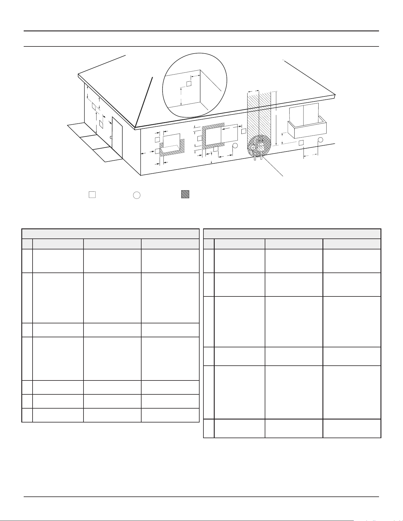
Venting Installation
Residential Gas Water Heaters • 33
SIDEWALL TERMINATION CLEARANCES OTHER THAN DIRECT VENT
Fixed
Closed
Operable
Fixed
closed
Operable
B
V
V
V
V
V
V
V
V
C
B
B
X
A
M
K
Regulator vent outlet
In the event no
regulator is present,
H and I can be
disregarded
.
V
Legend:
= Vent terminal
X
= Air supply inlet
= Area where terminal is not permitted
B
B
J
F
X
B
L
E
D
Inside
corner detail
V
A
G
H
15 ft
I
Figure 24. Other than Direct Vent Using Outside Air
Vent terminal clearances for “Direct Vent” installations. Direct Vent configurations use outdoor air for combustion.
Termination Clearances for Sidewall Direct Vent
Type of Clearance
Canadian Installations
1
US Installations
2
A
Clearance above
grade, veranda,
porch, deck or
balcony
12 inches (30 cm) 12 inches (30 cm)
B
Clearance to window
or door that may be
opened
• 6 in (15 cm) for appli-
ances ≤ 10,000 Btuh
(3 kW)
• 12 in (30 cm) for ap-
pliances > 10,000 Btuh
(3 kW) and ≤ 100,000
Btuh (30 kW),
• 36 in (91 cm) for appli-
ances > 100,000 Btuh
(30 kW)
• 4 feet (1.2 m) below or
to side of opening;
• 1 foot (30 cm) above
opening
C
Clearance to perma-
nently closed window
6 inches (15 cm)* 6 inches (15 cm)*
D
Vertical clearance
to ventilated soffit
located above the
terminal within a
horizontal distance of
2 feet (61 cm) from
the center line of the
terminal
12 inches (30 cm) 12 inches (30 cm)
E
Clearance to unventi-
lated soffit
12 inches (30 cm) 12 inches (30 cm)
F
Clearance to outside
corner
2 feet (60 cm)* 2 feet (60 cm)*
G
Clearance to inside
corner
18 inches (45 cm)* 18 inches (45 cm)*
Termination Clearances for Sidewall Direct Vent
Type of Clearance
Canadian Installations
1
US Installations
2
H
Clearance to each
side of center line ex-
tended above meter/
regulator assembly
3 ft. (91 cm) within a
height 15 ft. (4.6 m)
Clearance in accordance
with local installation
codes and the require-
ments of the gas supplier
I
Clearance to service
regulator vent outlet
3 ft. (1.83 m)
Clearance in accordance
with local installation
codes and the require-
ments of the gas supplier
J
Clearance to a non
mechanical air supply
inlet into building or
combustion air inlet
to any other appli-
ance
• 6 in (15 cm) for appli-
ances ≤ 10,000 Btuh
(3 kW)
• 12 in (30 cm) for ap-
pliances > 10,000 Btuh
(3 kW) and ≤ 100,000
Btuh (30 kW)
• 36 in (91 cm) for appli-
ances >100,000 Btuh
(30 kW)
• 4 feet (1.2 m) below or
to side of opening;
• 1 foot (30 cm) above
opening
K
Clearance to a
mechanical air supply
inlet
6 feet (1.83 m)
3 feet (91 cm) above
if within 10 feet (3 m)
horizontally
L
Clearance above
paved sidewalk or
paved driveway
located on public
property
7 feet (2.13 m)†
7 ft. (2.13 m) for me-
chanical draft systems
(Category I appliances);
vents for Category II and
IV appliances cannot
be located above public
walkways or other areas
where condensate or va-
por can cause a nuisance
or hazard
M
Clearance under
veranda, porch, deck,
or balcony
12 inches (30 cm) ‡ 12 inches (30 cm) ‡
1 In accordance with the current
CSA B149.1, Natural Gas and Propane Installation Code.
2 In accordance with the current
ANSI Z223.1/NFPA 54, National Fuel Gas Code.
† A vent shall not terminate directly above a sidewalk or paved driveway that is located
between two single family dwellings and serves both dwellings where it may cause
hazardous frost or ice accumulations on adjacent property surfaces.
‡ Permitted only if veranda, porch, deck, or balcony is fully open on a minimum of two
sides beneath the floor.
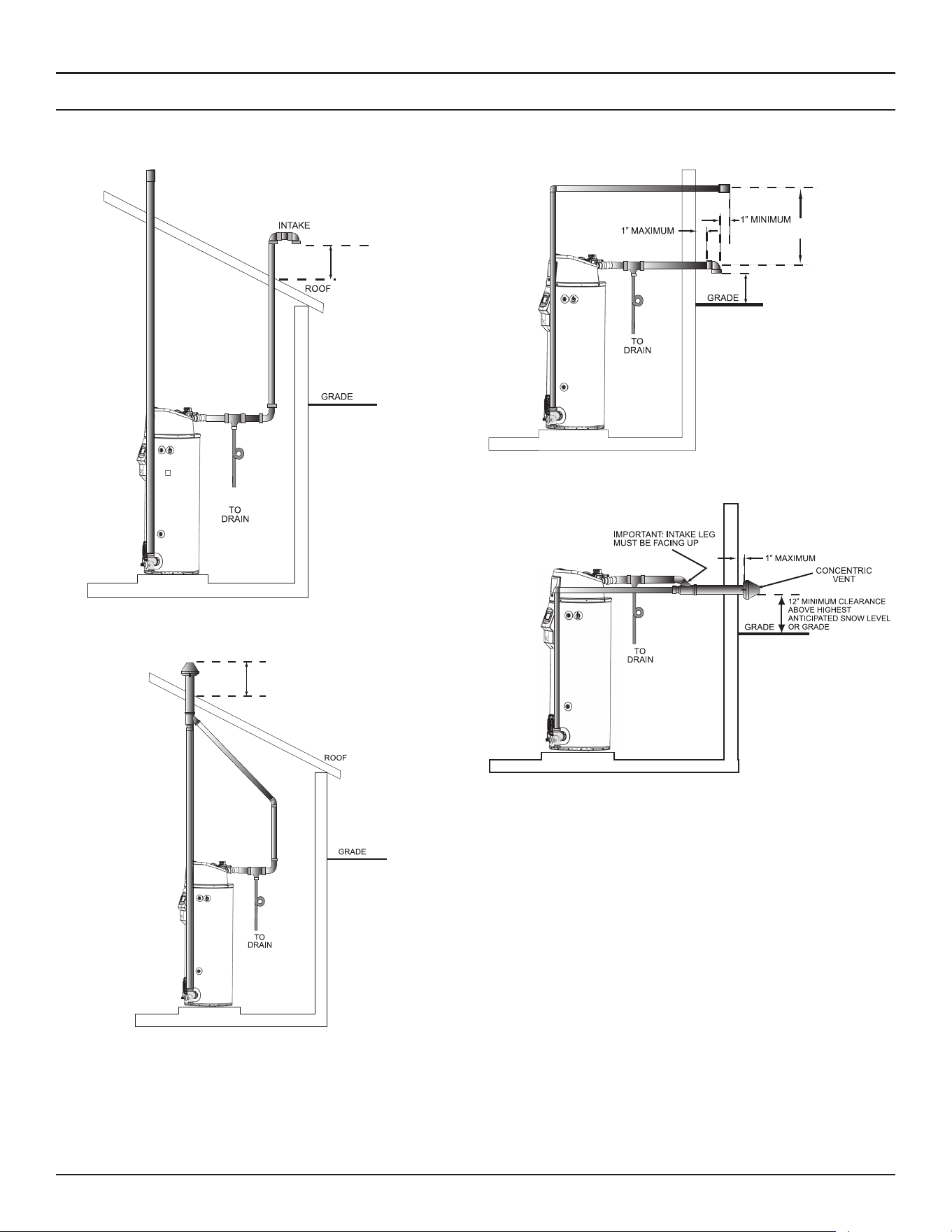
34 • Residential Gas Water Heaters
Venting Installation
DIRECT VENT DIAGRAM
Direct Vent combustion air intake drains are required in certain situations. See
Direct Vent Air Intake Moisture Protection
(page 30) and the
Figure
25
and
Figure 28
below.
12” MINIMUM CLEARANCE
ABOVE HIGHEST ANTICIPATED
SNOW LEVEL
EXHAUST
*
*
Figure 25. Direct Vent, Pitched Roof, Standard Termination
EXHAUST
*
*
12” MINIMUM CLEARANCE
ABOVE HIGHEST ANTICIPATED
SNOW LEVEL
Figure 26. Direct Vent Roof Vent Concentric
24” minimum
separation.
Exhaust must
be at same level
or above intake
terminal.
Snorkeling is allowed to
achieve proper clearance. The
snorkel must be securely
supported.
*
24”
12” minimum clearance
above highest anticipated
snow level or grade.
12”
*
*
Figure 27. Sidewall Vent - Typical
*
*
Figure 28. Sidewall Vent - Concentric
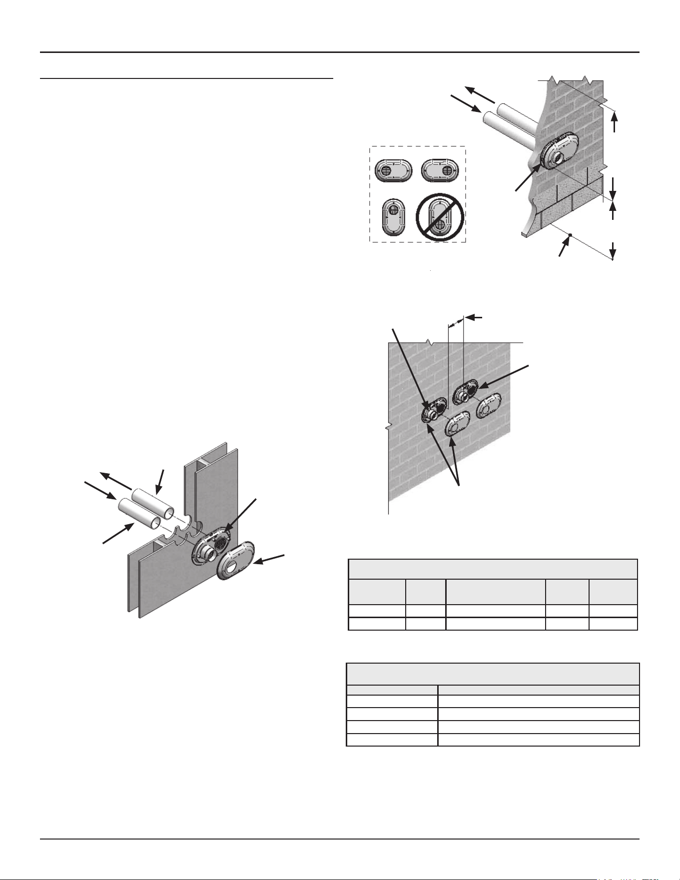
Venting Installation
Residential Gas Water Heaters • 35
LOW PROFILE TERMINATION INSTALLATION
This water heater is certified for sidewall direct venting with IPEX System
636 Low Profile Vent Kit. Follow instructions below for proper installations.
All termination kits must be located and installed in accordance with local
codes or the current edition of the
Natural Gas and Propane Installation
Code (CSA B149.1)
.
1. Once the proper location has been determined, cut 2 holes in the wall
large enough to accommodate the pipe. Pipe diameters and distance
between hole centers can be found in
Table 8
(page 35).
2. Slide both the intake and exhaust pipes through the holes. Solvent
cement both pipes to the base of the vent termination kit, follow
the solvent cementing procedures outlined in the
IPEX System 636
Installation Guide
, which is available on the web www.ipexinc.com.
3. To fasten the Base to the wall, use the supplied screws and anchors.
A 3/16” (5 mm) hole, 1-3/16” (30 mm) deep, will need to be drilled
for the anchors. Locate the anchor hole using the base as a template.
4. Screw the Cap to the Base using the supplied screws.
5. Once the vent termination and pipes are secured, the wall penetrations
will need to be sealed from the interior using a PVC-compatible sealant
material.
6. All vent pipes and air inlets must terminate at the same height to avoid
possibility of severe personal injury, death, or substantial property
damage.
7. Operate heater through one heat cycle to ensure combustion-air and
vent pipes are properly connected to concentric vent termination
connections.
Vent Base
Vent Cap
Air Inlet
Piping
Vent (Exhaust)
Piping
Figure 29. Low Profile Air Inlet/Exhaust Termination
To Heater Intake
Air Connection
From Heater Vent
Pipe Connection
Vent/Air
Termination
12”
Min to
Over-
Hang
12”
Min
Grade or
Snow Line
Possible Orientations
Figure 30. Low-Profile Vent Clearances
12” Min between Edge of Air Inlet
and Adjacent Vent
(Exhaust) Outlet
Air Inlet
Vent/Air
Termination
Vent (Exhaust)
Figure 31. Multiple Low-Profile Vent Termination Configuration
Table 8. Low Profile Termination Kits - Dimensions
AOS Kit Number
IPEX Part
Number
Description
Pipe
Outside
Diameter
Hole
Spacing
(ctr to ctr)
100187903 196984 2” Flush Mount Vent Kit 2.375” 5.6”
100187887 196985 3” Flush Mount Vent Kit 3.5” 5.6”
Table 9. Low Profile Vent Kit Contains
Qty Item Description
1 Base (two holes)
1 Cap (one hole)
8 Stainless Steel Screws
4 Plastic Anchors
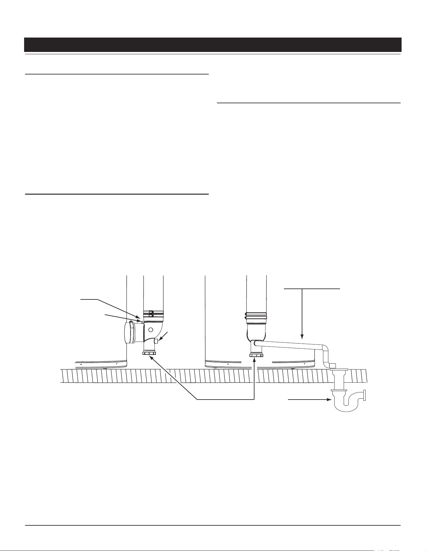
36 • Residential Gas Water Heaters
WATER HEATER INSTALLATION
CONDENSATE DRAIN INSTALLATION
Installation must conform with these instructions and local building codes.
Field-supplied materials required for installation include:
• Approved PVC cement and PVC primer.
• 1/2 inch PVC pipe - minimum length to equal the distance between
the water heater and a suitable building drain.
• 1/2 inch PVC fittings (elbows, couplings, and adapters) necessary
to install a condensate drain line between the Exhaust/Condensate
Elbow Assembly and a suitable building drain.
• Floor mounted standoffs to brace the drain line.
Installation Notes
1. The condensate drains from the water heater’s covered by this
instruction have pH levels between 4.3 and 5.0. Install a commercially
available neutralizing kit if required by local codes. Lower pH levels are
acidic. Do not connect a metal condensate drain line, such as copper
pipe, to the water heater for this reason.
2. The field-installed condensate drain line must not be less than 1/2
inch PVC in size.
3. The exhaust elbow has a built in condensate trap. Do not install an
additional trap in the condensate drain piping. Do not remove, modify
or alter the factory condensate trap.
Installation Instructions
1. Ensure the water heater’s Enable/Disable switch is in the “Disable”
position.
2. Install a 1/2 inch PVC condensate drain line between condensate drain
connection on the Exhaust/Condensate Elbow and a suitable building
drain. The condensate line must slope to an open drain. See
Figure 28
.
3. Terminate the condensate drain piping near the drain. See Figure 28.
Note:
In cold climates it is recommended the condensate drain be
terminated at a suitable drain inside the building.
4. Ensure the condensate drain line is not elevated above the condensate
drain connection on the Exhaust/Condensate Elbow. See
Figure 28
.
5. Brace the condensate drain line with floor-mounted standoffs every
three feet.
6. Ensure that the condensate drains freely during start up. See
Start Up
(page 39).
7. Condensate clean out cap must be on and tight when unit is in
operation.
CONDENSATE DRAIN
LINE - FIELD INSTALLED
BUILDING
DRAIN
1/2” NPT
CONDENSATE
DRAIN
CONNECTION
CONDENSATE
CLEANOUT
EXHAUST/CONDENSATE
(VENT) ELBOW
PRESSURE PORT
Figure 32. Condensate Drain Installation
Water heater Installation
Residential Gas Water Heaters • 37
GAS PIPING
Make sure gas supplied is same type listed on model rating plate. The inlet
gas pressure must not exceed 14 inch water column (3.5 kPa) for natural
and propane gas (LP). The minimum inlet gas pressure shown on rating
plate is that which will permit firing at rated input.
Schedule 40 Steel or Wrought Iron Pipe is the preferred material for
the gas line of this water heater. It is imperative to follow the sizing
recommendations in the latest version of the National Fuel Gas Code if
Corrugated Stainless Steel Tubing (CSST) is used as the gas line for this
water heater.
SEDIMENT TRAPS
• Contaminants in gas lines can cause fire or
explosions.
• Clean all gas piping before installation.
• Install drip leg in accordance with NFPA 54 or
CSA-B1491.
⚠
WARNING
Fire and Explosion Hazard
A sediment trap shall be installed as close to the gas inlet of the water
heater as practical at the time of water heater installation. The sediment
trap shall be either a tee fitting with a capped nipple in the bottom outlet
or other device recognized as an effective sediment trap.
Contaminants in the gas lines may cause improper operation of the gas
control valve that may result in fire or explosion. Before attaching the gas
line be sure that all gas pipe is clean on the inside. To trap any dirt or foreign
material in the gas supply line, a sediment trap must be incorporated in the
piping. The sediment trap must be readily accessible. Install in accordance
requirements in
Gas Piping
. Refer to the current edition of the
National Fuel
Gas Code (ANSI Z223.1/NFPA 54)
or the
Natural Gas and Propane Installation
Code (CAN/CSA B149.1).
Gas piping can leak gas from fi�ngs and connec�ons if
it is not sealed properly. Gas leaks can cause fires and
explosions resul�ng in severe injury or death.
• Use joint compound or thread sealer tape compatible
with the type of gas you are using.
• Leak test all gas connections before placing the water
heater in operation.
• Disconnect gas piping at main gas shutoff valve before
leak testing.
• Install sediment trap in accordance with NFPA 54 or
CAN/CSA B149.1.
⚠
WARNING
Fire and Explosion Hazard
Use pipe joint compound or thread sealer tape marked as being resistant
to the action of petroleum [Propane (LP)] gases.
The water heater and its gas connection must be leak tested before placing
the water heater in operation.
The water heater and its individual Shut-off valve shall be disconnected
from the gas supply piping system during any pressure testing of that
system at test pressures in excess of 1/2 pound per square inch (3.5
kPa). It shall be isolated from the gas supply piping system by closing its
individual manual Shut-off valve during any pressure testing of the gas
supply piping system at test pressures equal to or less than 1/2 pound
per square inch (3.5 kPa).
Fire and Explosion Hazard
An improper field conversion from one
type of gas to another could cause
potentially dangerous conditions that may
cause an explosion or fire resulting in
property damage, bodily injury or death.
Do not attempt to convert a water heater
without consulting A. O. Smith.
⚠
WARNING
ELECTRICAL WIRING
All electrical work must be installed in accordance with the
National
Electrical Code, ANSI/NFPA 70
or the
Canadian Electrical Code, CSA C22.1
and local requirements.
When installed, the water heater must be electrically grounded in
accordance with local codes or, in the absence of local codes, with the
National Electrical Code, ANSI/NFPA 70
or the
Canadian Electrical Code,
CSA C22.1.
If any of the original wire as supplied with the water heater must be
replaced, it must be replaced with 105°C rated wiring or its equivalent,
except in the burner housing. In this case 200°C rated wire must be used.
DEDICATED POWER WIRING AND BREAKERS
Dedicated power supply wires, neutral wires, ground wiring, and dedicated
circuit breakers often prevent electrical line noise and are required when
installing the water heater.
Note: This water heater should not be connected to an electrical supply
with a Ground Fault Circuit Interrupter (GFCI) or Arc Fault Circuit
Interrupter (AFCI) with Integral GFCI protection as defined in
NFPA
70, CSA C22.1
and
UL 943
.
Read the requirements in
Power Supply
(page 20) before connecting
power.
Enable / Disable Circuit
The water heaters covered in this manual are equipped with an enable/
disable circuit for use with field-supplied external supervisory controls,
such as time clocks or Building Management Systems. The enable/disable
circuit may be used to disable heating operation during periods when the
building is unoccupied or there is no demand for hot water.
To use the enable/disable circuit, it must first be activated by selecting
the “Use External Enable” from the UIM. Field-supplied wiring is then
installed between the water heater’s control board enclosure and a set of
“dry contacts” (no voltage or load) on the field-supplied external control.
Note: The water heater’s enable/disable circuit is a switching circuit only:
Do not apply external voltage or connect any load (i.e., relay coil)
to this circuit. This will damage the circuit board and is not covered
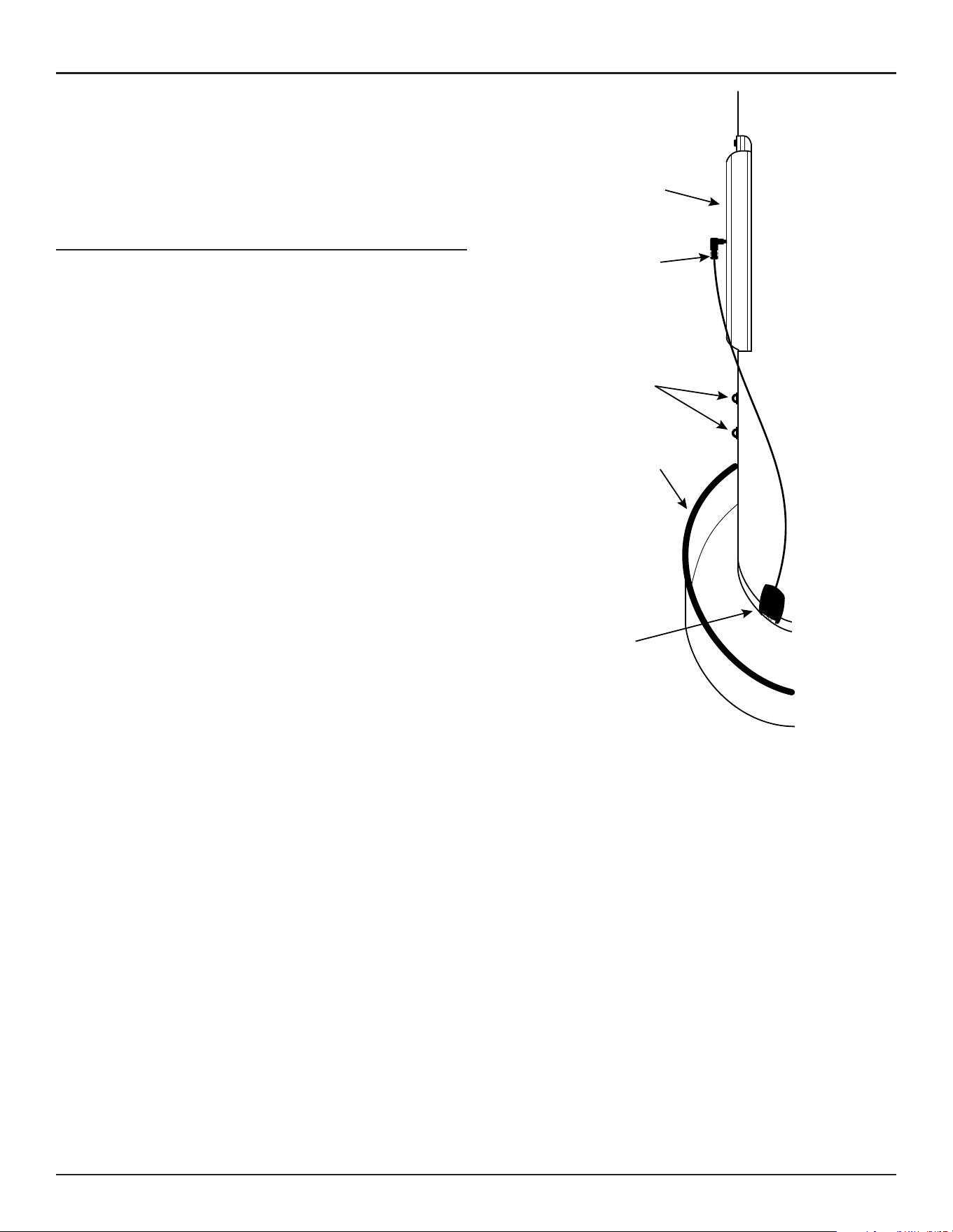
38 • Residential Gas Water Heaters
Water heater Installation
under the limited warranty. See the Residential Water Heater
Limited Warranty supplied with this water heater.
Note: Ensure the water heater is protected from freezing temperatures
when water heating operation is disabled. Damage to the water
heater caused by freezing temperatures is not covered under
the limited warranty. See the Residential Water Heater Limited
Warranty supplied with this water heater.
LEAK DETECTION MODULE
The water heaters covered by this manual have a water leak protection
feature that senses the buildup of water in the vicinity of the appliance,
setting off al alarm to alert the end user. Please follow installation
instructions in included kit.
Sensor
(Inside Drain Pan)
Drain Pan
Wire Mounts
Connector
Cleanout Cover
Access
Figure 33. Installation of Leak detection Module
Residential Gas Water Heaters • 39
START UP
PRIOR TO START UP
Installation and start up of this water heater requires abilities and skills
equivalent to that of a licensed tradesman in the field involved, see
Qualifications on page 7.
DO NOT USE THIS APPLIANCE IF ANY PART HAS BEEN EXPOSED TO FLOODING
OR WATER DAMAGE
. Immediately call a qualified service agency to inspect
the appliance and to make a determination on what steps should be taken
next. If the unit is exposed to the following, do not operate heater until all
corrective steps have been External fire
1. Damage
2. Firing without water
Light the water heater in accordance with the Lighting and Operation
Instruction label on the water heater and in this manual Lighting the Water
Heater on page 49.
The water heaters covered by this manual are equipped with an electronic
control system, which automatically sequences the Combustion Blower,
pre and post purging of the combustion chamber, the spark transformer,
the gas valve, Main Burner ignition, and flame sensing. The control system
will lock out after three unsuccessful ignition attempts. See Control System
Operation on page 41.
Start-Up Preparation
Before attempting start up, thoroughly study and familiarize yourself with
the exact Sequence Of Operation (page 54). Ensure the water heater is
properly grounded. Flame sensing requires an adequate earth ground. If
the water heater is not properly grounded it will cause ignition failure.
Be certain that the water heater is full of water, that air is purged from the
gas and water lines and that there are no leaks in the gas and water lines.
Ensure all inlet water valves are open.
Filling the Water Heater
To avoid water heater damage, fill tank with water
before operating.
CAUTION
Property Damage Hazard
Never use this water heater unless it is completely full of water. To prevent
damage to the tank, the tank must be filled with water. Water must flow
from the hot water faucet before turning ON gas to the water heater.
To fill the water heater with water:
1. Close the water heater drain valve by turning the handle to the right
(clockwise). The drain valve is on the lower front of the water heater.
2. Open the cold water supply valve to the water heater.
Note:
The cold water supply valve must be left open when the
water heater is in use.
3. To insure complete filling of the tank, allow air to exit by opening the
nearest hot water faucet. Allow water to run until a constant flow is
obtained. This will let air out of the water heater and the piping.
4. Check all water piping and connections for leaks. Repair as needed.
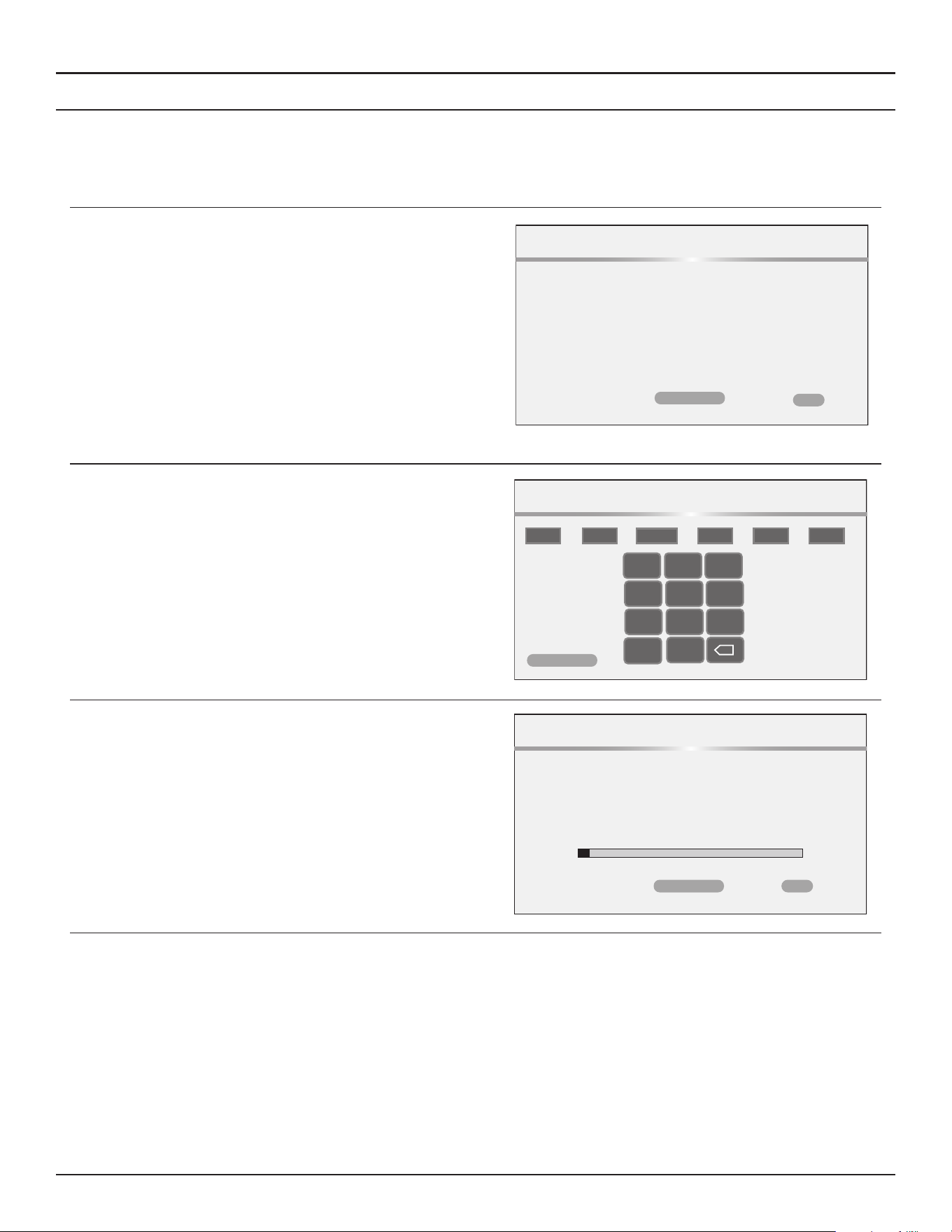
40 • Residential Gas Water Heaters
Start Up
GAS CALIBRATION
At the initial start up of the heater, an initial calibration routine must run.
This initial calibration may take up to 15 minutes.
During this initialization, any burner heat demand will be blocked.
After calibration, the continuous monitoring function becomes active.
This function can trigger a new calibration in case a gas quality change
is detected or there is a manual intervention by the qualified service
technician.
1. Click click ‘Confirm’ to proceed with the calibration.
Please press confirm to start the calibration.
Calibration
CONFIRM
BACK
2. Set the date and time, then click Confirm to continue with the
calibration.
Calibration will begin and progress screen will display.
DATE/TIME
MONTH DAY YEAR HOURS MINUTES AM/PM
4
28
2025
/ /
12
53
PM
- :
1 2 3
TAB
4 5 6
7 8 9
0
CONFIRM
CANCEL
3. Click Confirm to begin the calibration process.
Note:
Calibration may take up to 15 minutes.
When the calibration is complete, you will be returned to the home
screen.
It is normal for the first ignition following the calibration process to
be rough.
Calibrating
(May take up to 15 minutes)
Calibration
CONFIRM
BACK
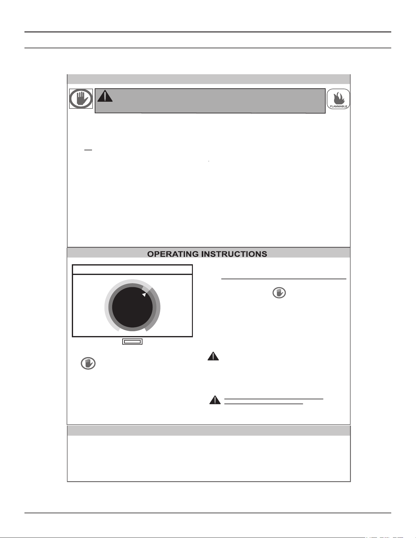
Start Up
Residential Gas Water Heaters • 41
LIGHTING INSTRUCTIONS
The instruction label below is affixed to the water heaters that are covered by this manual at the factory and must be followed when lighting and
operating the water heater.
FOR YOUR SAFETY READ BEFOR LIGHTING
WARNING: If you do not follow these instructions exactly, a fire or
explosion may result causing property damage, personal injury,
or loss of life.
BEFORE OPERATING: ENTIRE SYSTEM MUST BE FILLED
WITH WATER AND AIR PURGED FROM ALL LINES
This appliance does not have a pilot. It is equipped with
an ignition device which automatically lights the burner.
Do not try to light the burner by hand.
BEFORE OPERATING, smell all around the appliance
area for gas. Be sure to smell next to the floor because
gas is havier than air and will settle to the floor.
A.
B.
“WHAT TO DO IF YOU SMELL GAS”
• Do not try to light the appliance.
• Do no touch any electrical switch; do not use
any telephone in your building.
• Immediately call your gas supplier from a
neighbor’s phone. Follow the gas supplier’s
instructions.
• If you connot reach your gas supplier, call the
fire department.
Use only your hand to push in the control buttons.
Never use tools. If the control buttons will not push
in, don’t try to repair them, call a qualified service
technician. Force or attempted repair may result in
fire or explosion
C.
Do not use this appliance if any part has been under
water. Immediately contact a qualified installer or
service agency to replace a flooded water heater. Do
not attempt to repair the service unit. It must be
replaced.
D.
STANDBY-HOLD
SYSTEM OK
49°C
49°C
SETPOINT
ENABLE/DISABLE
SWITCH
STOP! Read the safety information above
on this label
Set the Enable/Disable switch on the control
panel to the Enable position.
1.
2.
Set the thermostat to the lowest setting.
3.
Set the Enable/Disable switch on the control
panel to the Disable position.
4.
This appliance is equipped with a device which
automatically lights the burner.
DO NOT TRY TO LIGHT THE BURNER BY HAND.
5.
Wait five (5) minutes to clear out any gas.
If you then smell gas, STOP! Follow “B” in the
safety information above on this label. If you don’t
smell gas, go to the next step.
6.
Turn on all electrical power to the appliance.
7.
Set the Enable/Disable switch on the control panel
to the Enable position.
8.
Set the thermostat to the desired setting.
9.
CAUTION: Hotter water increases the risk of
scald injury. Consult the instruction manual
before changing temperature
10.
If the appliance will not operate, follow the instruc-
tions “TO TURN OFF GAS TO APPLIANCE” and
call your technician or gas supplier.
WARNING: TURN OFF ALL ELECTRIC
POWER BEFORE SERVICING.
Set the thermostat to the lowest setting.
1.
Set the Enable/Disable switch on the control
panel to the Disable position.
2.
Turn off all electrical power to the appliance if
service is to be performed.
3.
TO TURN OFF GAS TO APPLIANCE
Figure 34. Lighting Instructions Label
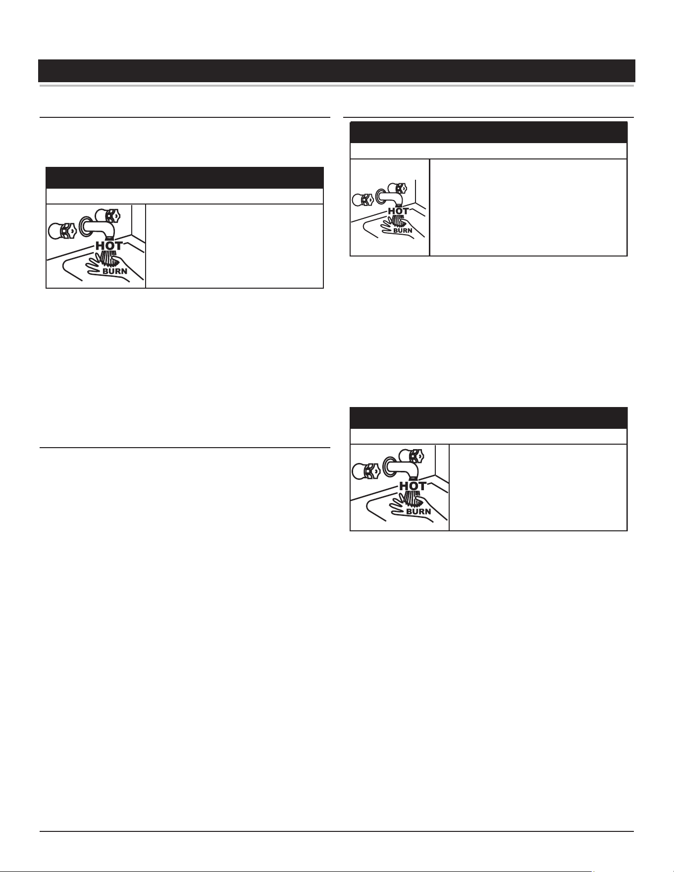
42 • Residential Gas Water Heaters
TEMPERATURE REGULATION
LIMITING THE RISK OF SCALDING
For a variety of reasons, water heaters can produce water that is much
hotter than its temperature setting. Take precautions to prevent this higher
temperature water from reaching the water fixtures.
The temperature of the water in the water
heater can exceed the thermostat se�ng and
be hot enough to cause burns.
To reduce the risk of unusually hot water
reaching the fixtures in the house, install point
of use thermosta�c mixing valves at each point
of use.
⚠
WARNING
Burn Hazard
According to a national standard,
Performance Requirements for Water
Temperature Limiting Devices (ASSE 1070)
and many local plumbing codes,
the water heater’s gas control valve should not be used as the sole means
to regulate water temperature and avoid scalds.
A properly adjusted thermostatic mixing valve at each point of use allows
you to set the tank temperature to a higher setting without increasing
risk of scalds. A higher temperature setting allows the tank to provide
much more hot water and can help provide proper water temperatures
for appliances such as dishwashers and washing machines.
HIGH TEMPERATURE LIMIT CONTROL
This water heater is equipped with a non-adjustable high-temperature
limit control.
The high-temperature limit control is located inside the Temperature Probe.
See
Figure 1
(page 10) and
Figure 2
(page 11).
If the high-temperature limit control activates due to abnormally high water
temperatures in the storage tank, the control system will immediately
deenergize the gas valve and end the current heating cycle. The control
system will "lock out" disabling further heating operation. The control
system will display the “High Temp Limit Exceeded” Fault message on the
LCD screen. It is important that a Qualified Service Agent be contacted to
determine the reason for the high-temperature limit control activation
before resetting the high-temperature limit control. Once the reason has
been determined and corrected the high-temperature limit control can
be reset as follows:
If the high-temperature limit control activates, the water temperature must
drop below 140°F (60°C) before the control system can be reset. Once the
water temperature has cooled below this point, the power supply to the
water heater must be turned off and on again to reset the control system.
THERMOSTAT CONTROL
Because of the increased risk from scalding, if you
set the water heater’s gas control knob higher than
120°F (49°C), install thermosta�c point-of-use
mixing valves at each point of use. Due to the
increased risk of scalding, do not set the tempera-
ture of the thermosta�c mixing valves above 120°F
(49°C).
⚠
DANGER
Burn Hazard
Hot water temperatures required for automatic dishwasher and laundry
use can cause scald burns resulting in serious personal injury and/or death.
Table 10
(page 43)
shows the approximate time-to-burn relationship for
normal adult skin.
The temperature at which injury occurs varies with the person’s age and
duration of exposure. The slower response time of children, the elderly
or disabled persons increases the hazards to them. If anyone using hot
water provided by the water heater being installed fits into one of these
groups or if there is a local code or state law requiring a certain water
temperature at the point of use, then special precautions must be taken.
The temperature of the water in the water
heater can exceed the thermostat se�ng and
be hot enough to cause burns.
If you choose a higher temperature se�ng,
install thermosta�c mixing valves at each
point-of-use to help avoid scalding.
⚠
WARNING
Burn Hazard
In addition to using the lowest possible temperature setting that satisfies
the demand of the application a means, such as a thermostatic point-of-use
mixing valve, for example, can be used at the hot water taps used by these
people to reduce the water temperature.
Check State and/or local codes for thermostatic point-of-use mixing valve
requirements and installation practices.
Never allow small children to use a hot water tap or draw their own bath
water. Never leave a child or disabled person unattended in a bathtub or
shower.
The water heater should be located in an area where the general public
does not have access to set temperatures.
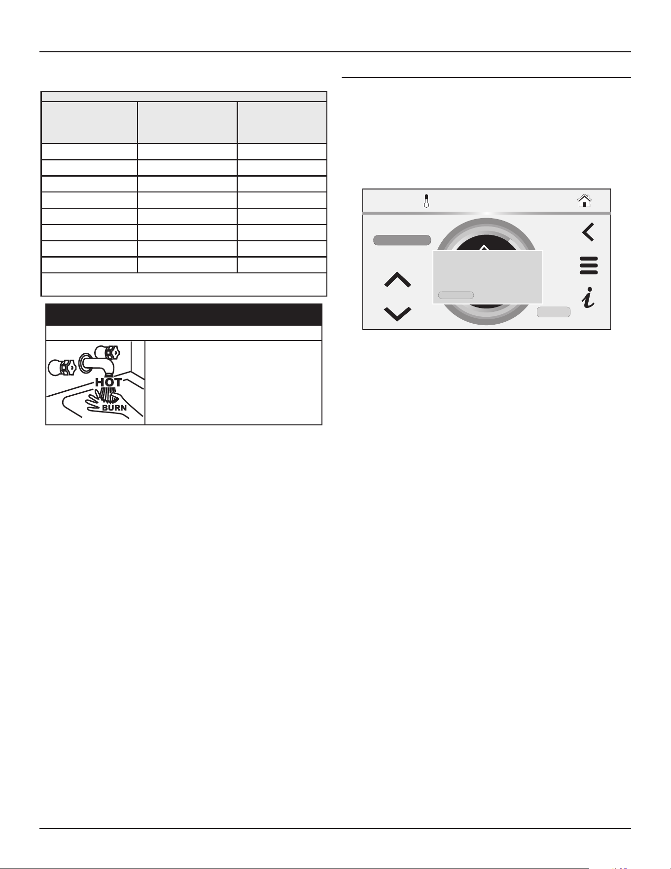
Temperature Regulation
Residential Gas Water Heaters • 43
Setting the Operating Set Point at 120°F (49°C) will reduce the risk of scalds.
Some States require settings at specific lower temperatures.
Table 10. Time to Burn at Different Temperatures
Water Temperature
°F (°C)
Time for 1st Degree Burn
(Less Severe Burns)
Time for Permanent Burns
2nd & 3rd Degree
(Most Severe Burns
110 (43.3) (Normal shower temp.)
116 (46.7) (Pain threshold)
116 (46.7) 35 minutes 45 minutes
122 (50) 1 minute 5 minutes
131 (55) 5 seconds 25 seconds
140 (60) 2 seconds 5 seconds
149 (65) 1 second 2 seconds
154 (67.8) Instantaneous 1 second
(U.S. Government Memorandum, C.P.S.C., Peter L. Armstrong, Sept.
15, 1978)
The temperature of the water in the water
heater can exceed the thermostat se�ng and
be hot enough to cause burns.
To reduce the risk of unusually hot water
reaching the fixtures in the house, install point
of use thermosta�c mixing valves at each point
of use.
⚠
WARNING
Burn Hazard
The water heaters covered in this manual are equipped with an electronic
control system to regulate water temperature inside the storage tank. The
control system senses temperature from a factory-installed temperature
probe. See
Figure 1
(page 10) and
Figure 2
(page 11) for location.
The “Operating Set Point” is adjusted to regulate water temperature
inside the storage tank. This is an adjustable user setting in the control
system’s “Temperatures Menu.” This and all control system menus are
accessed through the UIM (user interface module) located on the front
of the water heater.
The Operating Set Point is adjustable from 90°F (32°C) to 160°F (71°C).
The factory setting is 120°F (49°C). See
Set Point Manager
(page 46)
for instructions on how to adjust the Operating Set Point and other user
settings.
Set the Operating Set Point at the lowest setting that produces an
acceptable hot water supply. This will always provide the most energy
efficient operation.
HIGH TEMPERATURE APPLICATIONS
Higher operating temperatures cause more wear on all water heaters
and will decrease the life span of the water heater. Consider installing a
small booster water heater for high temperature applications to raise the
outlet temperature from the larger primary water heater to the desired
point of use temperature.
Contact your local distributor or call the technical support phone number
listed on the back cover of this manual for further technical assistance.
150°F
SET POINT
SETPOINT MANAGER
MODE:
CANCEL
DIFFERENTIAL
10°F
ENTER
MANUAL
Setpoint changed:
New Setpoint is 130°F
Please confirm to continue:
CONFIRM CANCEL
Figure 35. Tank Temperature Set point
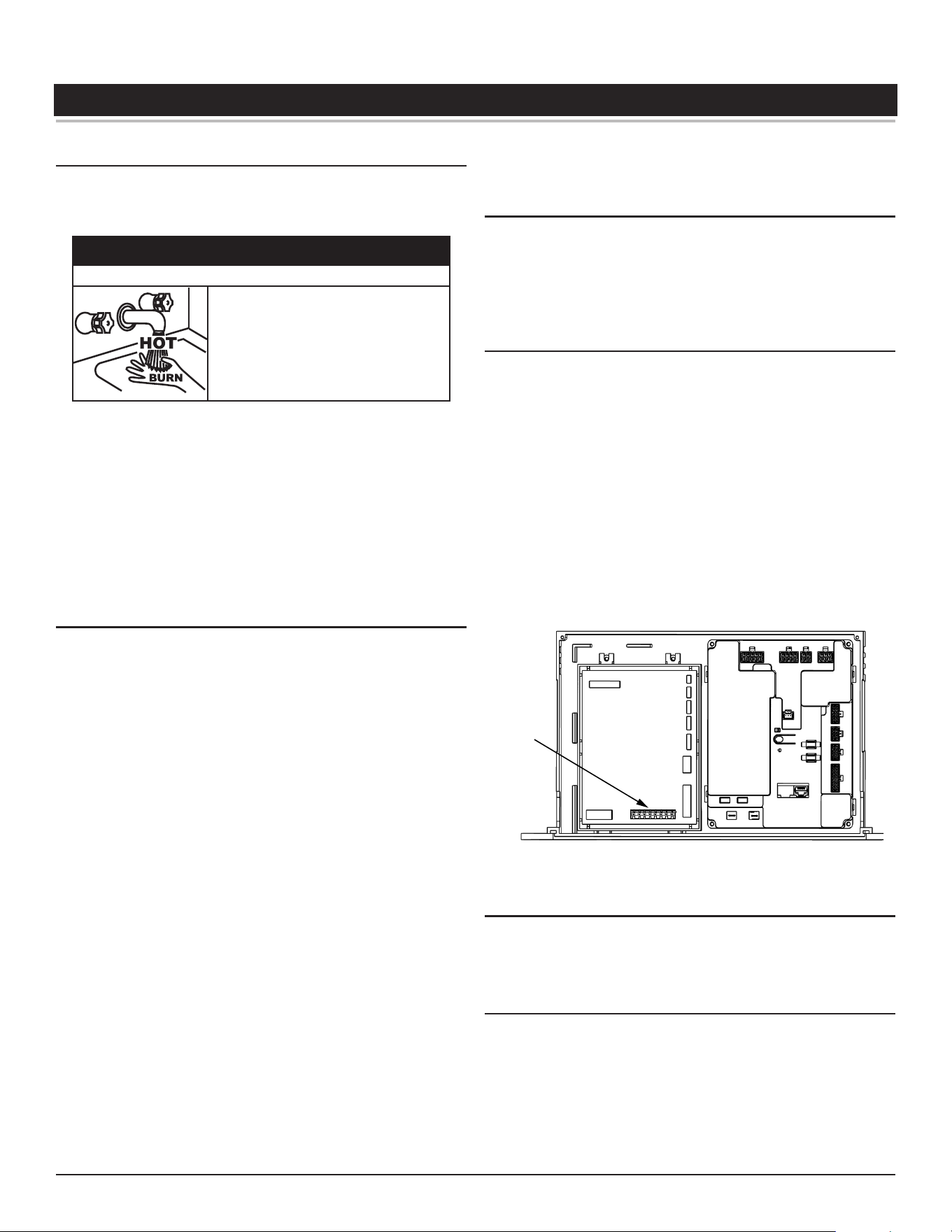
44 • Residential Gas Water Heaters
CONTROL SYSTEM OPERATION
LIMITING THE RISK OF SCALDING
For a variety of reasons, water heaters can produce water that is much
hotter than its temperature setting. Take precautions to prevent this higher
temperature water from reaching the water fixtures.
The temperature of the water in the water
heater can exceed the thermostat se�ng and
be hot enough to cause burns.
To reduce the risk of unusually hot water
reaching the fixtures in the house, install point
of use thermosta�c mixing valves at each point
of use.
⚠
WARNING
Burn Hazard
According to a national standard,
Performance Requirements for Water
Temperature Limiting Devices (ASSE 1070)
and many local plumbing codes,
the water heater’s gas control valve should not be used as the sole means
to regulate water temperature and avoid scalds.
A properly adjusted thermostatic mixing valve at each point of use allows
you to set the tank temperature to a higher setting without increasing
risk of scalds. A higher temperature setting allows the tank to provide
much more hot water and can help provide proper water temperatures
for appliances such as dishwashers and washing machines.
WI-FI
The water heaters covered in this manual feature a Wi-Fi functionality
that is enabled at the factory. If Wi-Fi is not required for installation, you
can be disabled it as follows:
1. Go to main menu screen
2. Select iCOMM icon
3. Wi-Fi Status should show “AP Mode” (If not scroll down to “Change to
AP Mode” line item and Enable)
4. Enable the Wi-Fi if it is showing as disabled
5. Using a phone or tablet go to the Wi-Fi settings and search available
networks
6. In the list of networks, there should be a name that is similar to
“iCOMMNextGenUIM-XXXXXXXX”. This is the website being broadcast
by the display on the water heater. Select this network.
7. After selecting the iCOMM network, a separate message may appear
asking for permission to Stay Connected to the selected network.
Select the option to stay connected. Under the selected network
name, there should be an indication that the Wi-Fi connected with
the above iCOMM network.
8. Open a new Internet browser window on the device.
9. The Internet browser may automatically go to the web address
192.168.0.1. If it doesn’t, type that number into the address bar. This
will bring up a page that looks similar to the following:
10. Find the network name on the left that corresponds to the local Wi-Fi
network, and select the Connect button to the right of it.
11. If the local network is password protected, a new screen will appear
asking for the password. Enter the password for the local network and
click Connect.
12. A confirmation message should appear indicating the Connection to
Wi-Fi was completed.
LOCKOUT FUNCTION
The water heaters covered in this manual feature a lockout functionality
that is disabled at the factory by default. If the lockout functionality is
required by the end user, the initial installer/contractor can access this
functionality and enable it through the UIM. See
Lockout Function
(page
54) for the procedure.
CONTROL SYSTEM OVERVIEW
The water heaters covered in this manual are equipped with an electronic
control system that regulates water temperature inside the storage tank.
Heating cycles and ignition are managed by the control system. The
high-temperature limit control, flame sensor, pressure switches, and
temperature probes are monitored by the control system. The combustion
blower, spark ignition transformer, gas valve and anode rods are all
powered by the control system.
The main components of the control system are a user interface module
(UIM), Temperature Regulation Control (TRC) and control system circuit
(CSC). The UIM is located on the top front side of the water heater. The
control boards are mounted on top of the water heater inside a protective
enclosure. This unit is equipped with an Enable/Disable switch. To operate
unit, make sure the switch is set to Enable. See
Features and Components
(page 10) for location of these and all water heater components.
TRC
CSC
J13
Figure 36. Control System Components
CONTROL SYSTEM NAVIGATION
All operational information and user settings are displayed and accessed
from the UIM. The UIM houses the control system's LCD Touch Display
(liquid crystal display).
The Home Screen
During normal operation, the control system displays the Home screen
on the LCD Touch Display, which is the default screen. The control system
returns to the Home screen when there are no active fault or alert
conditions or when there has been no user input for several minutes.
• Manufacturer and water heater model information displays in the
Title Bar at the top of the Home screen.
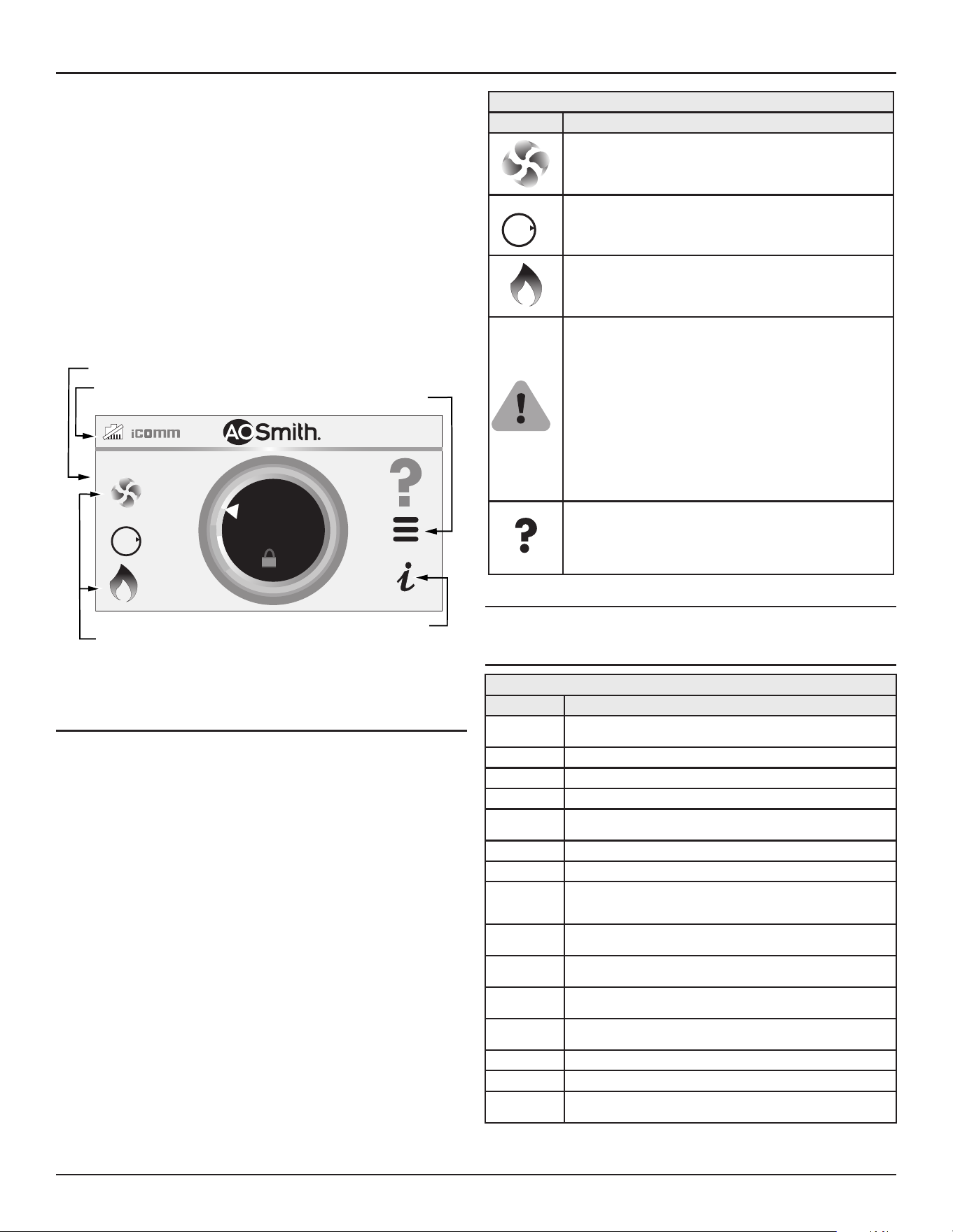
Control System Operation
Residential Gas Water Heaters • 45
• The Operating set point is shown in the middle of the Home screen.
This is the temperature at which the control system will maintain
the water inside the storage tank.
• Status is shown in the upper left. The status shows the current
operational state of the control system in real time.
• The light green band on the temperature dial shows the
temperature offset.
• The three horizontal lines on the Home screen will allow you to
access sub menus.
• The Home screen also displays animated status icons to convey
operational information. See
Table 11
(page 45)
for descriptions of
the status icons.
HEATING
118°F
120°F
SET POINT
OFF
GAS
O
N
Touch Display
Status
Icons
Title Bar
Menu:
(Operational Menus
are Multifunctional.)
Help
Figure 37. User Interface Module (UIM) Home Screen
Status Icons
The Status Icons are displayed on the Desktop screen and convey
operational and diagnostic information. The icons are described in the
table below.
Table 11. Status Icons
Icon Description
The Combustion Blower is energized.
OFF
GAS
O
N
The gas valve is being energized.
The control system has sensed flame at the Main Burner
from the flame sensor. See
Figure 42
(page 62) and
Figure 2
(page 11).
The control system has declared a fault condition and
must be inspected/serviced by a Qualified Service Agent.
Fault message details can be viewed in the Current Fault
menu. Heating operation is disabled (lock out) until the
condition that caused the fault is corrected. Power to the
water heater must be cycled off and on at the breaker to
reset the control system.
Note: Cycling power will not reset the control system if
the condition that caused the fault has not been
corrected.
The control system has declared an alert condition and
must be inspected/serviced by a Qualified Service Agent.
The water heater will continue to operate during an alert
condition.
Operating States
The current operational state of the water heater is displayed on the Desktop
screen as the "Status." The common operational states are described in the
table below.
Table 12. Operating States
State Description
Uncalibrated The unit is currently uncalibrated and must go through calibration
before use.
Calibration The unit is currently going through calibration procedure.
Standby Heater is waiting on a call for heat.
Initializing Initializing heater before regular heating.
Input
Verification
The unit has begun a burn cycle and is checking all safety circuits.
Pre-Purge The unit has begun a spark period to ignite the main burner.
Ignition The unit has begun a burn cycle and is checking safety circuits.
Inter-Purge After a failure to ignite the burner, the control is attempting to purge
any excess gas from the heater exchanger before another attempt to
light.
Heating The water heater has been properly lit, and the water in the tank is
being heated.
Post-Purge Combustion products are being pushed out of the heater exchanger
after a successful heating cycle.
System in Fault The water heater control has detected a fault. No further heating of the
water will be done until reset.
Blocked A condition is preventing a burn cycle that must clear before resuming
water heating.
Ext Ena External enable/disable switch is active on unit.
BMS BMS is active on unit.
Heater
Disabled
The heater has been disabled and will not heat water.
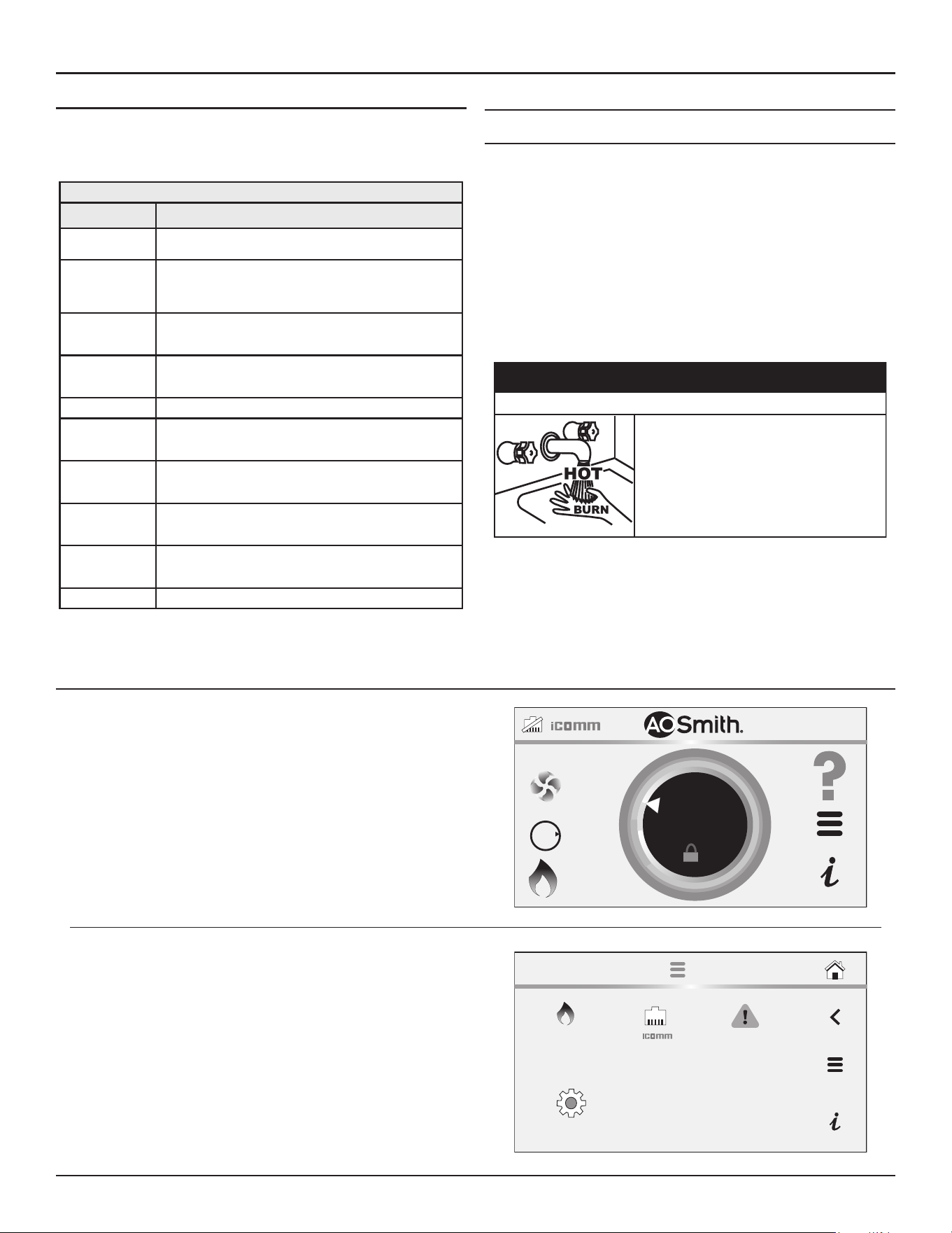
46 • Residential Gas Water Heaters
Control System Operation
Control System Menus
From the Desktop screen pressing "Menu" on the LCD Touch Display will
display the "Main Menu" this is where all control system menus are located.
The table below describes the control system menus.
Table 13. Control System Menus
Menu Description
Setpoint Manager Most commonly accessed menu. Contains the Operating Setpoint
and Differential user settings.
Heater Status This menu displays the current state of all pressure switches and
the high temperature limit control sensors. The on/off status of
the Combustion Blower, gas valve, igniter, flame sensor and other
monitored water heater components are displayed in this menu.
Display Settings Temperature units (°F or °C), the LCD appearance (brightness/
contrast) and back-light delay user adjustable settings are located
in this menu.
Heater Informa-
tion
Elapsed time of operation, total heating cycle time, heating cycle
count, heating on time along with UIM and control board software
revisions can be viewed in this menu.
Current Fault Displays any current alert or fault messages.
Fault History This control system menu retains a list of the last nine (9) fault and
alert messages with a time stamp. The newest event will replace
the oldest. Faults will clear after 30 days.
Fault Occurrence This control system menu retains a running total of how many
times each fault condition has occurred since the water heater
was first installed. The data does not clear and cannot be reset.
Restore This control system feature allows the user to restore control sys-
tem user settings to their factory default settings. Display Settings
preferences ARE NOT changed when factory defaults are restored.
Help Screens Text based operational and user information explaining how to
change user settings, navigate the control system menus and icon
descriptions.
Disabled The heater has been disabled and will not heat water.
USER SETTINGS & CONTROL SYSTEM MENUS
Operating Set-Point and Differential Adjustment
The Operating Set Point is adjustable from 90°F (42°C) to 180°F (82°C).
The factory setting is 120°F (49°C). The Differential is adjustable from 2°F
(1°C) to 20°F (11°C). The factory setting is 8°F (4°C). These user settings
are accessed from the Temperatures menu. The following instructions
will explain how to adjust these settings and navigate the control system
menus.
When the water temperature sensed by the control system from the Main
Temperature Probe reaches the Operating Set Point, the control system
ends the heating cycle. A heating cycle will be activated again when the
sensed water temperature drops below the Operating Set Point minus
the Differential setting.
The temperature of the water in the water
heater can exceed the thermostat se�ng and
be hot enough to cause burns.
If you choose a higher temperature se�ng,
install thermosta�c mixing valves at each
point-of-use to help avoid scalding.
⚠
WARNING
Burn Hazard
Note: Lower Differential settings may cause excessive heating cycles
(short-cycling) which can cause premature failure of heater
components. Set the Differential at the highest setting which
produces an acceptable hot water supply. Set the Operating Set
Point to the lowest setting which produces an acceptable hot water
supply for most efficient use.
Set Point Manager
From the Set Point Manager, you can adjust the Differential Mode and
the Differential.
1. From the Home screen, press MENU icon. The “Main Menu” screen
will be displayed.
Note:
The differential is indicated by the light green band on the
temperature dial.
BTH250-NAT
HEATING
118°F
120°F
OFF
GAS
O
N
SETPOINT
The Main Menu is where all control system menus are listed. See
Table 13
(page 46) for a complete list and description of control
system menus.
2. Press Heater Menu to access the Setpoint Manager Menu.
FAULTS
SETTINGS
MAIN MENU
HEATER
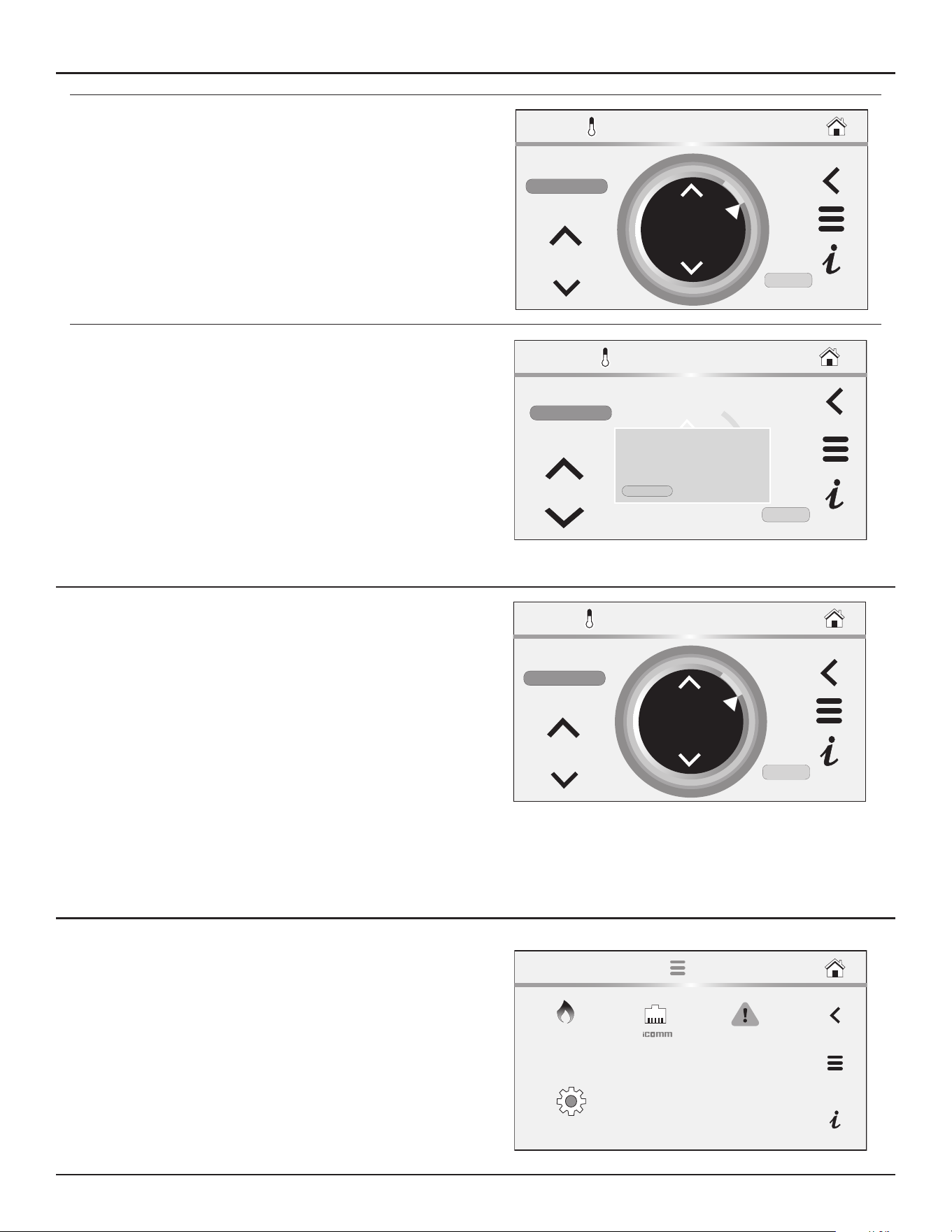
Control System Operation
Residential Gas Water Heaters • 47
3. Press Heater: Setpoint Manager to access the temperature setpoint
menu.
4. Use the arrow Buttons to change the current setting.
Note:
Higher Temperature settings increase wear and operating
costs. Set the Operating Set Point to the lowest setting which
produces an acceptable hot water supply. This will always
provide the most energy efficient operation and longer life.
150°F
SETPOINT
SETPOINT MANAGER
MODE:
CANCEL
DIFFERENTIAL
10°F
ENTER
MANUAL
5. Tap “CONFIRM” to save the new setting. Press “CANCEL” to discard
changes and return to the previously saved setting.
150°F
SET POINT
SETPOINT MANAGER
MODE:
CANCEL
DIFFERENTIAL
10°F
ENTER
MANUAL
Setpoint changed:
New Setpoint is 130°F
Please confirm to continue:
CONFIRM CANCEL
6. To change the differential setting: change the mode from automatic to
manual, then use the up and down arrows on the differential to change
setting. Confirm to keep changes or Press the Cancel button to return
to the previously saved settings.
•
Differential Mode
- Operating mode with an Intelligent Demand
Response (IDR). This mode allows the water heater to reduce
preset differential to a lower setting so that the appliance will
more rapidly respond to large draws to maintain water outlet
temperature. This mode is enabled at the factory by default, but
can be disabled in the field if required.
•
Differential
- Adjustable user setting that changes the tank
temperature differential with a range of 2° to 20°F. The factory
setting is 8°F.
These settings are adjusted in the same way described in
Operating Set-
Point and Differential Adjustment
(page 46).
150°F
SETPOINT
SETPOINT MANAGER
MODE:
CANCEL
DIFFERENTIAL
10°F
ENTER
MANUAL
iCOMM Menu
1. From the Home screen, press MENU icon.
The “Main Menu” screen will be displayed.
2. Press the iCOMM icon to access the iCOMM screen.
FAULTS
SETTINGS
MAIN MENU
HEATER
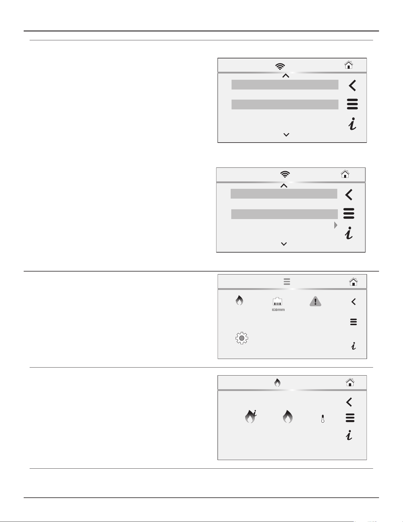
48 • Residential Gas Water Heaters
Control System Operation
The iCOMM screen displays the following Wi-Fi information:
•
Wi-Fi Status
- displays status of Wi-Fi connection.
•
Ethernet
- displays status of Ethernet connection.
•
iCOMM Server
- displays status the iCOMM server.
•
Wi-Fi MAC
- displays the Wi-Fi MAC number.
•
Ethernet MAC
- displays the Ethernet MAC number.
•
DSN
- displays the Device Serial Number (DSN). Used for
registration of the heater.
•
Wi-Fi Strength
- displays Wi-Fi signal strength as a series of bars.
•
Wi-Fi Strength
- displays Wi-Fi signal strength dBm units.
Wi-Fi
- Wi-Fi functionality is enabled at the factory. In the bottom
portion of the menu, the Wi-Fi can be disabled by selecting the
Enabled>
marker and selecting the
Disable
option. This is the only
item on this screen that can be adjusted. The other items are for view
and information purposes only.
Top of Menu
iCOMM
Wi-Fi Status Connected
Ethernet Not Connected
Registration Registered
iCOMM Server Connected
Bottom of Menu
DSN
AC000W006323619
Wi-Fi Strength
0Bars
Enabled
Wi-Fi
-128dBm
Wi-Fi Strength
iCOMM
Heater Information Menu
1. From the Home screen, press MENU icon.
The “Main Menu” screen will be displayed.
2. From the Main Menu, press the Heater icon to access the Heater menu.
FAULTS
SETTINGS
MAIN MENU
HEATER
3. Press the Heater Information icon from the Heater menu to enter the
Heater Information screen.
HEATER
INFORMATION
HEATER
STATUS
SETPOINT
MANAGER
HEATER MENU
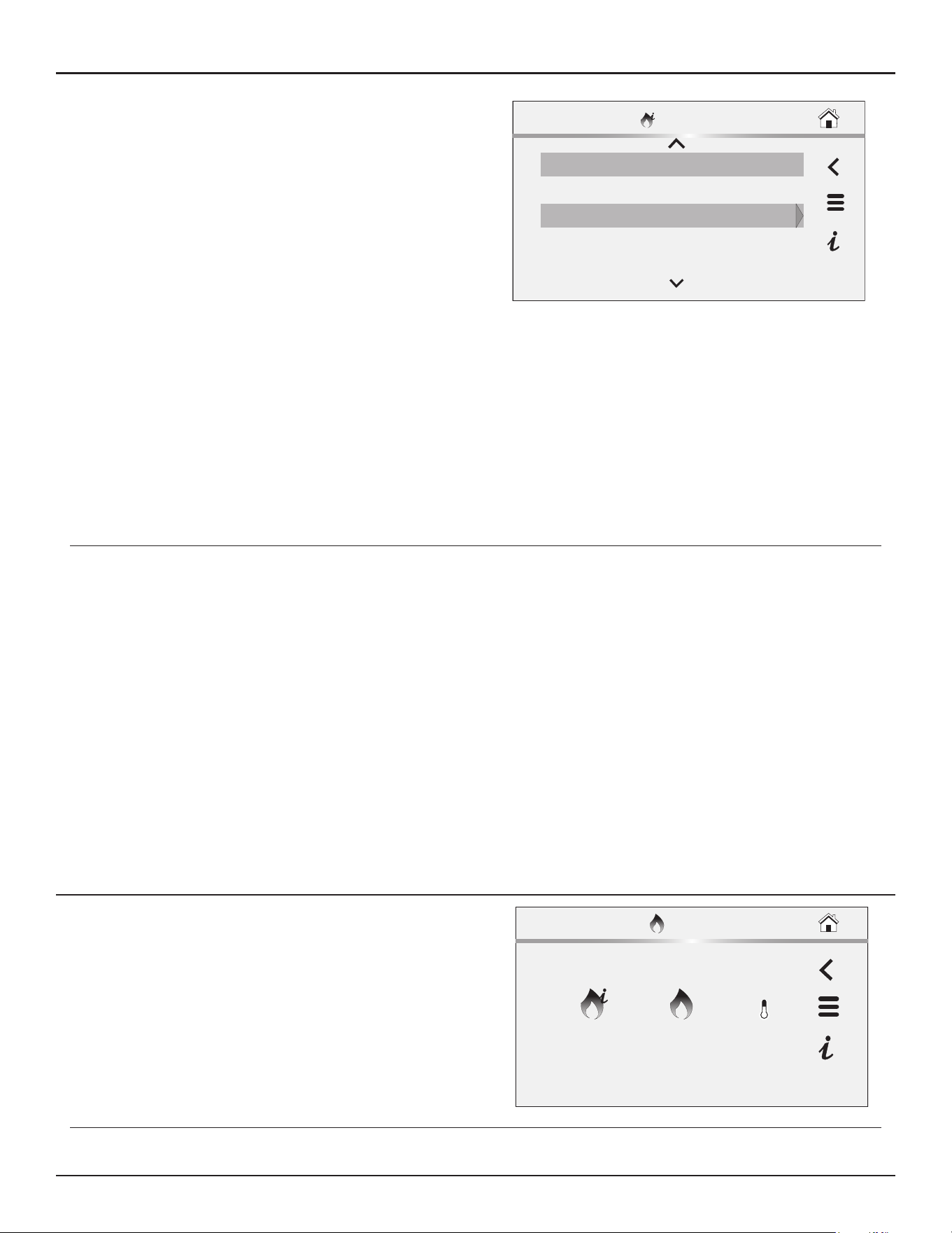
Control System Operation
Residential Gas Water Heaters • 49
This screen contains non adjustable operational information.
•
Elapsed Time
- Total accumulated time the control system (water
heater) has been energized.
•
Total Heat Time
- Total accumulated time the control system has
been in the heating operating state; burner run time.
•
Total Cycle Counter
- Total accumulated count of heating cycles.
•
Ignition Failure Count
– Total accumulated count of ignition
failures.
•
Flame Loss Count
- Total accumulated count of flame losses.
•
TRC Version -
Software version for TRC board.
•
UIM Version
- Software version for user interface module.
•
Serial Number
- Serial number of the water heater.
•
Model Number
- Model number of the water heater
•
CSC Version
- Software version for CSC board.
•
CPAM1 Version
- Software version for CPAM1.
•
CPAM2 Version
- Software version for CPAM2.
•
Building Management Version
- Software version for Building
Management System.
•
Water Valve Control Version -
Software version for the water
valve control.
•
NANODE Version -
Software version for NANODE.
Elapsed Time 0 Days 0 Hrs 31 Mins 37
Total Heat Time
0 Days 0 Hrs 10 Mins 0 Secs
Yes
External Enable Status
YesUse External Enable
HEATER INFO
Historical data is stored in the NFC board key. If this board is removed
or damaged during servicing the historical data will be lost and heater
will no longer operate. The NFC board key should never be replaced
unless directed by Technical Support.
The Elapsed Time, Burner On Time and Cycle Count indicate age,
usage and wear.
If the Cycle Count per day is high (divide cycle count by days to
determine cycles per day) or the cycle duration is short (determine
burner on time total minutes, divide burner on time total minutes
by cycle count) consider raising the Differential setting to avoid short
cycling and excessive component wear. See
Operating Set-Point and
Differential Adjustment
(page 46).
This historical data can also be used to assist facilities managers in
forecasting planned replacement of equipment to help avoid lengthy
and costly hot water supply interruptions.
Heater Status Menu
1. From the Home screen, press MENU icon.
The “Main Menu” screen will be displayed.
2. From the Main Menu, press
Heater: Heater Information
to access the
Heater Information screen.
HEATER
INFORMATION
HEATER
STATUS
SETPOINT
MANAGER
HEATER MENU
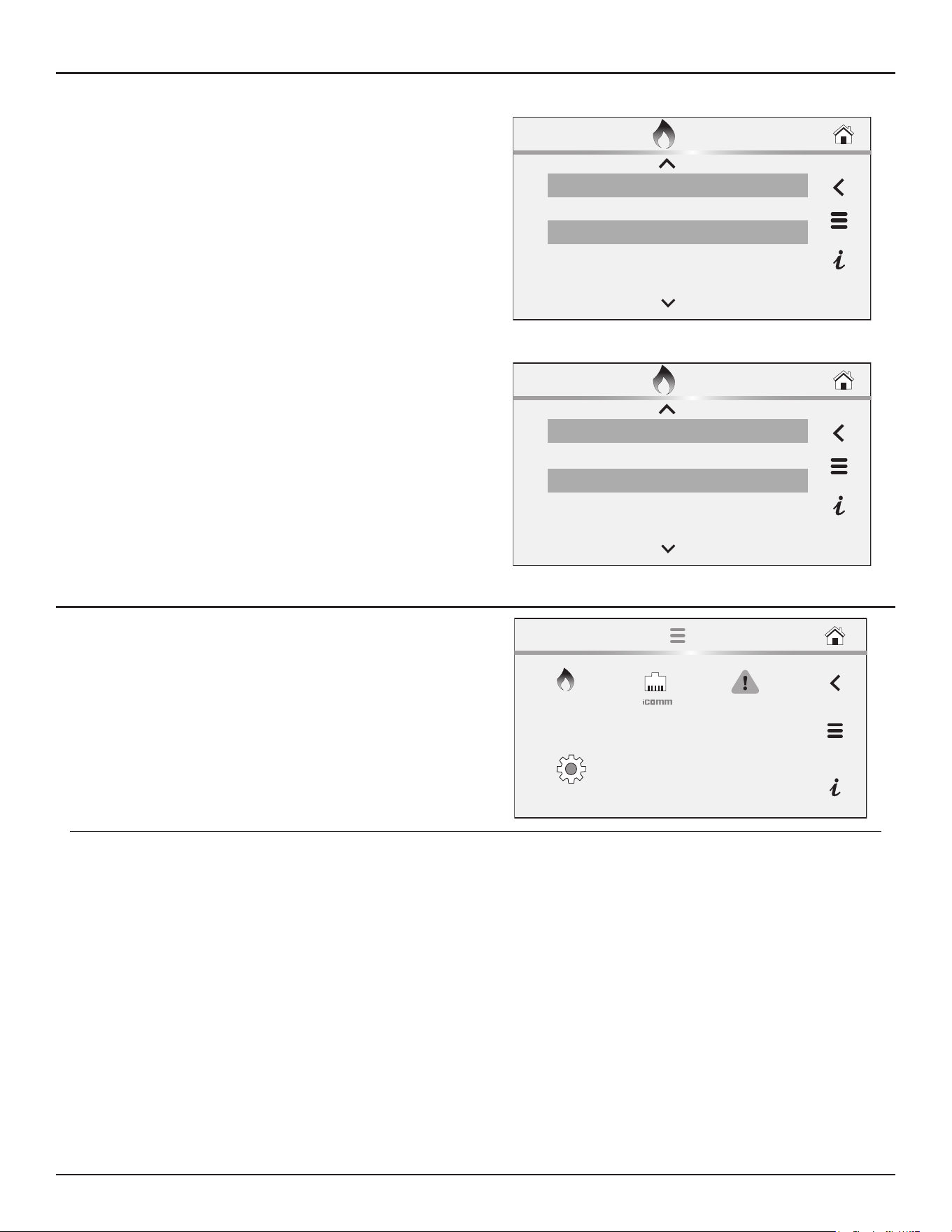
50 • Residential Gas Water Heaters
Control System Operation
The Heater Status menu displays the following information:
•
Status
- Indicates whether the heater is Enabled or Disabled.
•
Blocked Inlet PS
- Indicates if the Inlet is blocked.
•
Blocked Outlet PS
- Indicates if the Outlet is blocked.
•
Igniter On
- Indicates if the Igniter is operational
•
Gas Valve On
- Indicates if the gas valve is on.
•
Flame Detected
- Indicates if flame is detected.
•
Blower RPM
- Indicates the blower RPMs
•
Main Temperature
- Temperature reading of the main
temperature probe.
•
Lower Temperature
- Temperature reading of the lower
temperature probe.
•
Anode Current
– Current reading of anode
•
Anode Tank Voltage
– Voltage of anode tank
•
Anode Drive Voltage
– Voltage of anode drive
•
Water Valve 1 Status
– Current status of Water Valve 1
•
Water Valve 1 Error
– Error in Water Valve 1
•
Water Valve 2 Status
- Current status of Water Valve 2
•
Water Valve 2 Error
- Error in Water Valve 2
•
Water Valve 3 Status
- Current status of Water Valve 3
•
Water Valve 3 Error
- Error in Water Valve 3
Top of Menu
HEATER STATUS
Status: HEATER DISABLED
Blocked Inlet PS Open
Blocked Outlet PS Open
Igniter Yes
Bottom of Menu
HEATER STATUS
Water Valve 2 Status Yes
Water Valve 2 Error 3 Tries
Water Valve 3 Error 15rpm
Water Valve 3 Status 500rpm
Display Settings Menu
1. From the Home screen, press MENU icon.
The “Main Menu” screen will be displayed.
2. From the Main Menu, press the Settings icon to access the Settings
screen.
FAULTS
SETTINGS
MAIN MENU
HEATER
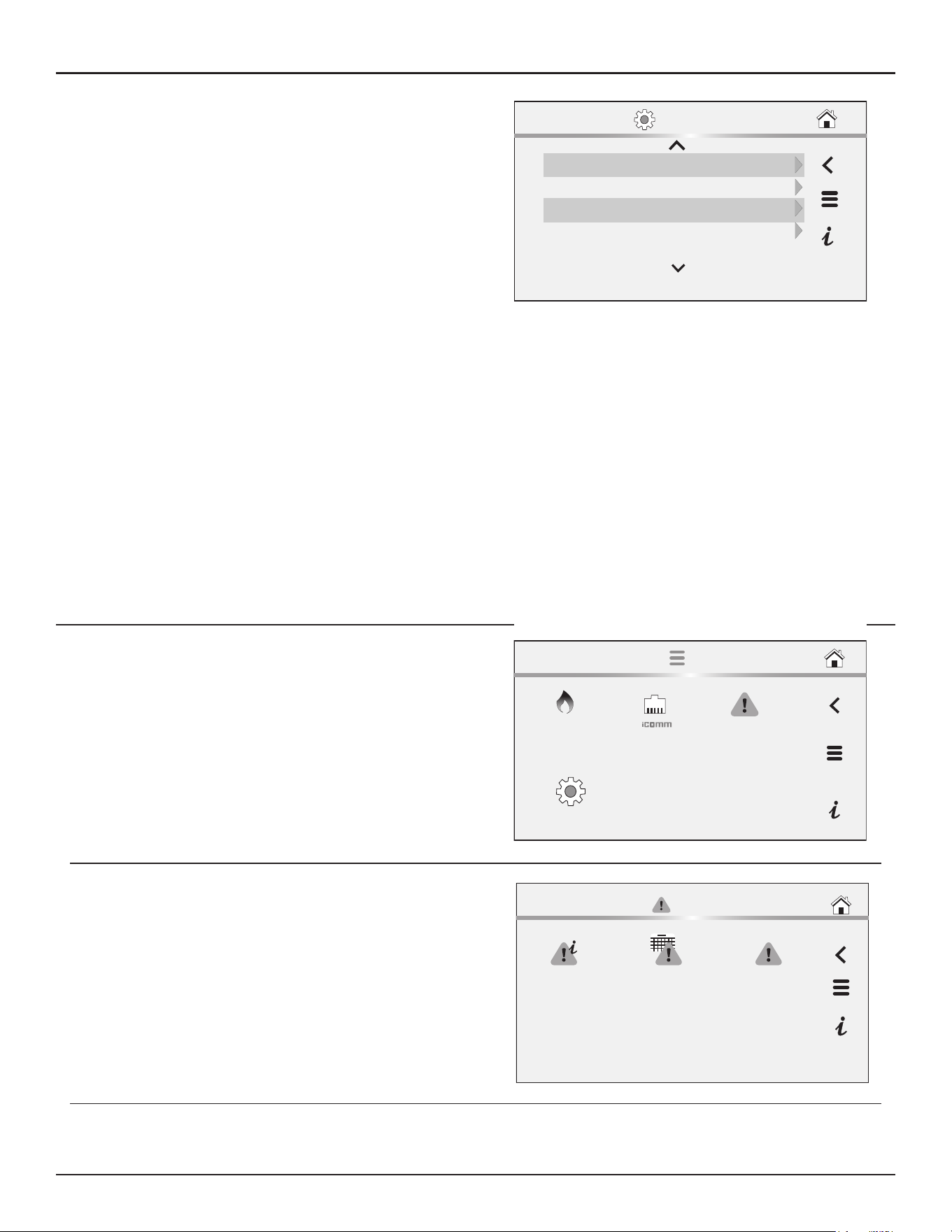
Control System Operation
Residential Gas Water Heaters • 51
The Settings screen contains adjustable display options for viewing
information on the LCD screen.
•
Temperature Units
- Adjustable user setting that changes
temperature units display to Celsius °C or Fahrenheit °F.
•
Backlight Delay
- Adjustable user setting that determines how
long the LCD backlight remains illuminated after a key has been
pressed. Available settings are; Always Off, 10, 30 or 60 seconds
and Always On.
•
Brightness
- Adjustable user setting to adjust the LCD screen
contrast between text and background.
• These settings are adjusted in the same way as described
Operating Set-Point and Differential Adjustment
(page 46).
• Lock setpoint manager
• Date/Time
• Lock
• Show Contact
• Current Contact Info
• Leak Detection
• Audio Alert
• Tank Temp Probe Offset
• Use External Enable
• Disable Modulation
• Water Valve Cycle Time
• Language
Temp Units °F
Display Brightness 8
09/09/2020 12:34 AMDate/Time
30 secBacklight
SETTINGS
Current Fault
1. From the Home screen, press MENU icon.
The “Main Menu” screen will be displayed.
2. From the Main Menu, press the Faults icon to access the Fault Menu.
FAULTS
SETTINGS
MAIN MENU
HEATER
3. From the Fault Menu, press the Current Fault or Current Alert icon to
access the Current Fault screen.
FAULT MENU
FAULT
OCCURRENCE
FAULT
HISTORY
CURRENT
FAULT (NONE)
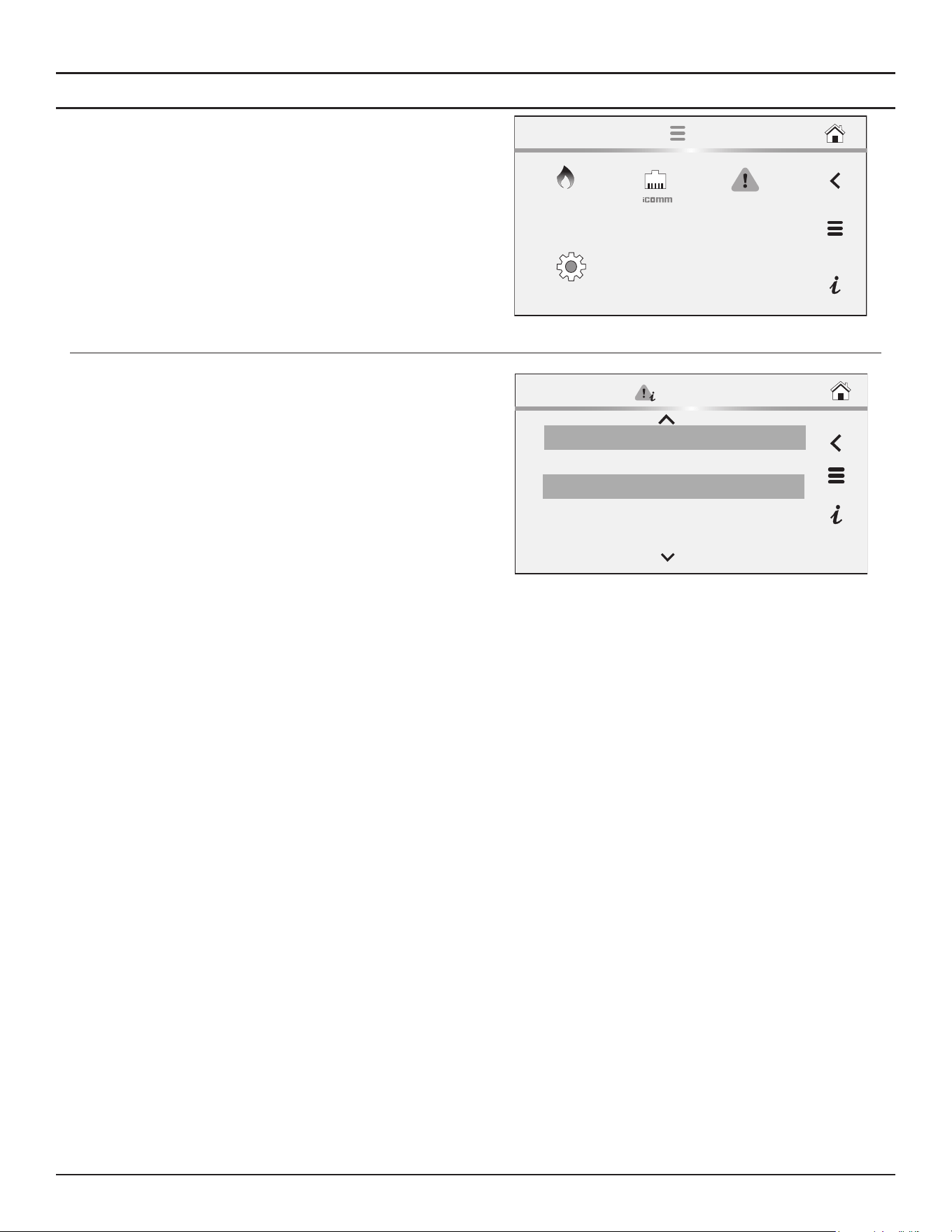
Control System Operation
Residential Gas Water Heaters • 53
Fault Occurrence Menu
1. From the Home screen, press MENU icon.
The “Main Menu” screen will be displayed.
2. From the Main Menu, press the Faults icon to access the Fault Menu.
FAULTS
SETTINGS
MAIN MENU
HEATER
3. From the Faults Menu, press the Fault Occurrence icon to access the
Fault Occurrence screen.
The Fault Occurrence screen contains a running total of how many
times each Fault condition has occurred since the water heater was
first installed.
Hardware Fault 1
Software Failure 7
0
Software and FMM Key Incompatible
4
Missing Module
Fault Occurrence
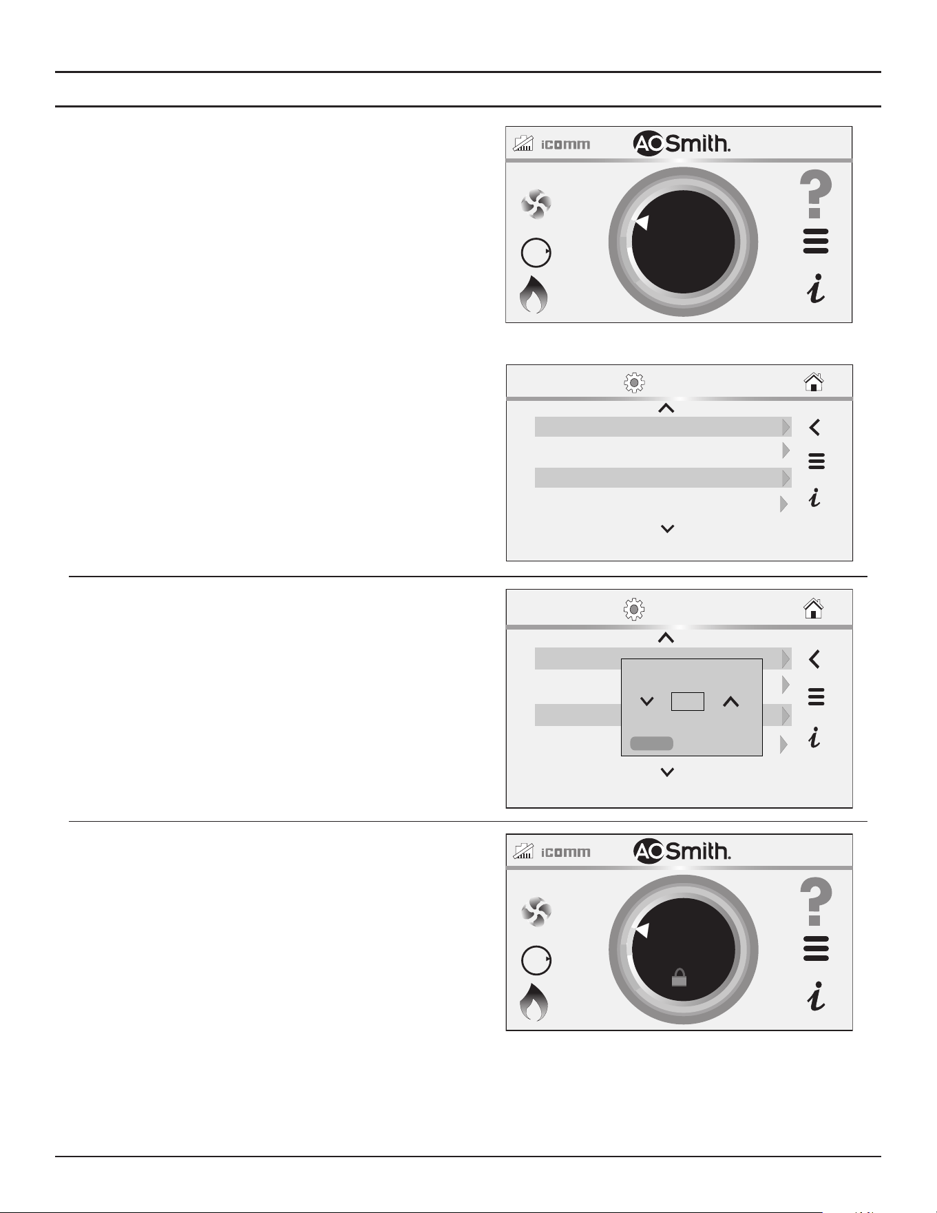
54 • Residential Gas Water Heaters
Control System Operation
Lockout Function
1. From the Home screen, press MENU icon.
The “Main Menu” screen will be displayed.
2. From the Main Menu, press the Settings icon to access the Settings
screen.
3. Use the arrow buttons to scroll through the list to the Lock item.
4. Click on the arrow to the right to access the Lock dialog box.
BTH250-NAT
HEATING
118°F
120°F
SETPOINT
OFF
GAS
O
N
30 secBacklight
SETTINGS
Temp Units °F
04/28/2025 12:34 AMDate/Time
Brightness
8
5. Use the arrows in the Lock dialog box to toggle Yes to enable the lock
or No to disable the lock.
Note:
The lock is disabled by default from the factory.
Click Confirm to implement your selection.
SETTINGS
30 secBacklight
Temp Units °F
04/28/2025 12:34 AMDate/Time
Brightness
8
Lock
No
CONFIRM
CANCEL
6. Press and hold on the lock icon on the Home screen to unlock the
Setpoint settings
BTH250-NAT
HEATING
118°F
120°F
SETPOINT
OFF
GAS
O
N
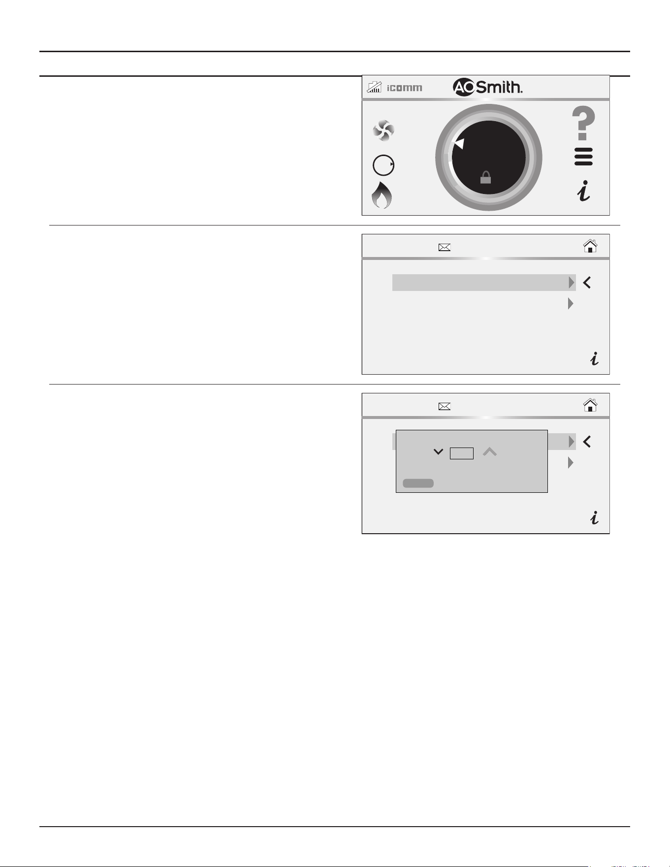
Control System Operation
Residential Gas Water Heaters • 55
Restore Factory Defaults Function
1. Press and hold on the A. O. Smith logo on the Home screen.
The Service Information screen displays
BTH250-NAT
HEATING
118°F
120°F
SETPOINT
OFF
GAS
O
N
2. Select Restore User Defaults on the Service Information screen.
SERVICE INFORMATION
Restore User Defaults Display
Access Code
3. Ensure TRC is selected in the list menu, then press the Confirm button.
The original factory settings of the water heater are restored.
SERVICE INFORMATION
Restore User Defaults Display
Access Code
Restore User Defaults
TRC
CONFIRM
CANCEL
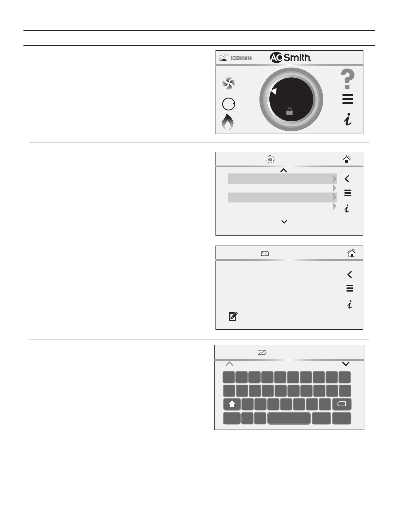
56 • Residential Gas Water Heaters
Control System Operation
Service Contact Information
The control system has a menu that Installing contractors and/or service
agents can access to enter their contact information for customers. This
contact information will be displayed with all Fault and Alert messages.
1. From the Home screen, press the Main Menu icon. The Main Menu
screen displays.
2. From the Main Menu screen, press the Settings icon.
BTH250-NAT
HEATING
118°F
120°F
OFF
GAS
O
N
SETPOINT
3. Scroll down to the Settings Menu and select the Current Contact Info
item. The Contact Information screen displays.
Temp Units °F
Display Brightness 8
09/09/2020 12:34 AMDate/Time
30 secBacklight
SETTINGS
CONTACT INFORMATION
John Doe
Widgits LLC
123-456-7890
www.widgitsllc.com
4. To edit a contact information item, select it and press the Pencil icon.
5. Edit the item using the keyboard. Press the Save Key to save your data
after each entry.
Note: You can enable or disable the display of Contact info by editing the
“Show Contact” item on the Settings Menu.
CONTACT INFORMATION
John Doe
Q W R T YE I O PU
A S F G HD K L ‘J
C V BX MNZ
.,123
SAVE EXIT
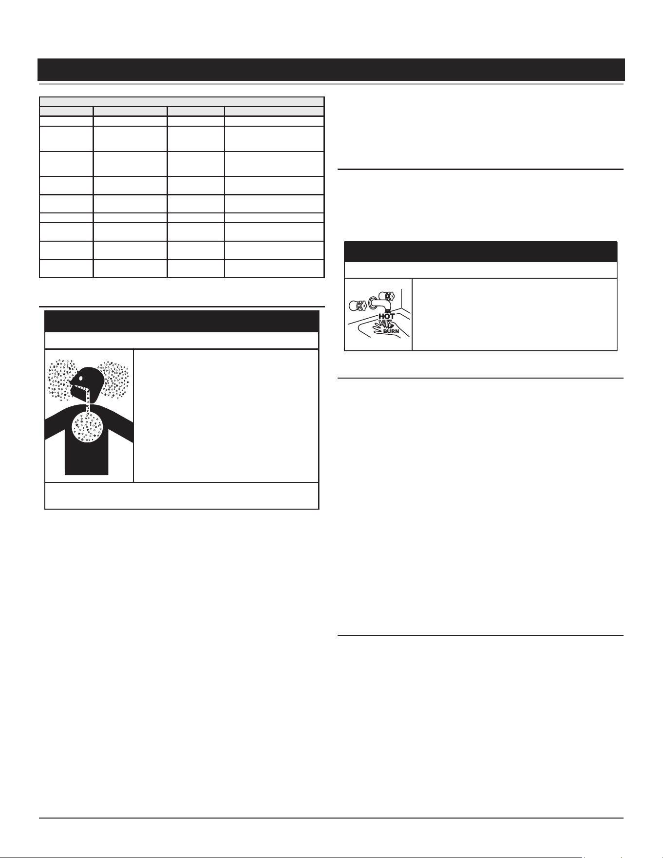
Residential Gas Water Heaters • 57
MAINTENANCE
Table 14. Maintenance Schedule
Component Operation Interval Reference
Tank Drain and Flush Every 6 Months See
Draining and Flushing.
Tank
Lime Scale Removal
(Water Less Than 25
Grains Hard)
Not Required N/A
Tank
Lime Scale Removal
(Water Greater Than
25 Grains Hard)
Annually
See
Lime Scale Removal
(page 58).
Burner Flames Inspection Every 3 Months
See
Burner Inspection and
Maintenance
(page 58).
Burner
Inspection/
Cleaning
As Needed
Contact qualified agency or
professional.
Moving Parts Lubrication Not Required N/A
Powered
Anodes
Inspection/
Cleaning
Annually
See
Anode Rod Maintenance
(page 59).
T&P Valve Test Operation Semi Annually
See
Temperature-Pressure
Relief Valve Test
(page 59).
Vent System Inspection Annually
See
Venting System Mainte-
nance
.
VENTING SYSTEM MAINTENANCE
• Flue gases may escape if vent pipe is not
connected.
•
Be alert for obstructed, sooted, or deteriorated
vent system to avoid serious injury or death.
• Do not store corrosive chemicals in the vicinity
of the water heater.
• Chemical corrosion of the flue and vent system
can cause serious injury or death.
• Analyze the entire vent system to make sure
that condensate will not become trapped in a
section of vent pipe and therefore reduce the
open cross sectional area of the vent.
Breathing carbon monoxide can cause brain damage or death.
Always read and understand instruction manual.
⚠
WARNING
Breathing Hazard - Carbon Monoxide Gas
At least once a year examine the vent system. Points of inspection are as follows:
1. Check for obstructions and/or deterioration of the intake air and/
or vent piping and the intake air and vent terminations. Replace
immediately where needed.
2. The debris screens in the intake air and vent terminations should be
cleaned of foreign material and soot.
Note:
Do not reach inside the vent termination when the heater is
in operation.
3. Check all vent system connections for leakage and repair or reseal as
necessary.
Be sure the vent piping is properly connected to prevent escape of
dangerous flue gasses which could cause deadly asphyxiation.
Obstructions and deteriorated vent systems may present serious health
risk or asphyxiation.
Chemical vapor corrosion of the flue and vent system may occur if air
for combustion contains certain chemical vapors. Spray can propellants,
cleaning solvents, refrigerator and air conditioner refrigerants, swimming
pool chemicals, calcium and sodium chloride, waxes, bleach and process
chemicals are typical compounds which are potentially corrosive.
If after inspection of the vent system you found sooting or deterioration,
something is wrong. Call the local gas utility to correct the problem and
clean or replace the flue and venting before resuming operation of the
water heater.
DRAINING AND FLUSHING
It is recommended that the water heater storage tank be drained and
flushed every 6 months to reduce sediment buildup. The water heater
should be drained if being shut down during freezing temperatures. See
Figure 1
(page 10) and
Figure 2
(page 11) for the location of the water
heater components described below.
⚠
DANGER
Burn Hazard
The discharge water from the drain valve is hot enough
to cause burns.
Keep your hands clear of the drain valve discharge
outlet.
Draining the Water Heater Storage Tank
1. Turn off the electrical supply to the water heater.
2. Turn off the gas supply at the Main Gas Shutoff Valve if the water heater
is going to be shut down for an extended period.
3. Ensure the cold water inlet valve is open.
4. Open a nearby hot water faucet and let the water run until the water
is no longer hot.
5. Close the cold water inlet valve to the water heater.
6. Connect a hose to the water heater drain valve and terminate it to an
adequate drain.
7. Open the water heater drain valve and allow all the water to drain
from the storage tank.
8. Close the water heater drain valve when all water in the storage tank
has drained.
9. Close the hot water faucet opened in Step 4.
10. If the water heater is going to be shut down for an extended period,
the drain valve should be left open.
Flushing the Water Heater Storage Tank
1. Turn off the electrical supply to the water heater.
2. Ensure the cold water inlet valve is open.
3. Open a nearby hot water faucet and let the water run until the water
is no longer hot. Then close the hot water faucet.
4. Connect a hose to the drain valve and terminate it to an adequate drain.
5. Ensure the drain hose is secured before and during the entire flushing
procedure. Flushing is performed with system water pressure applied
to the water heater.
6. Open the water heater drain valve to flush the storage tank.
7. Flush the water heater storage tank to remove sediment and allow the
water to flow until it runs clean.
8. Close the water heater drain valve when flushing is completed.
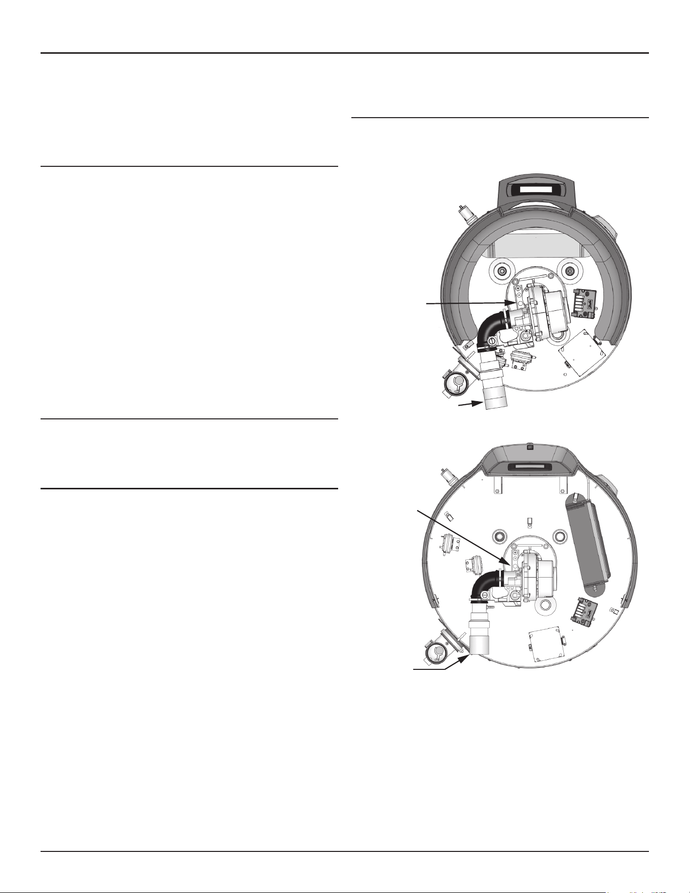
58 • Residential Gas Water Heaters
Maintenance
9. Remove the drain hose.
10. Fill the water heater. See
Filling the Water Heater
(page 39).
11. Turn on the electrical supply to place the water heater back in operation.
12. Allow the water heater to complete several heating cycles to ensure
it is operating properly.
LIME SCALE REMOVAL
When water is heated dissolved minerals in the water such as calcium
and magnesium carbonate (lime scale) become less soluble. As the water
temperature rises these minerals will precipitate or “fall out” of solution.
The amount of lime scale released from water is in direct proportion to
water temperature and usage. The higher the water temperature or water
usage, the more lime deposits are dropped out of the water.
Water hardness also affects lime scale accumulation. With the temperature
and usage being the same, hard water will release more lime scale than
softer water.
Lime scale reduces heating efficiency as it accumulates inside a water
heater. Heating transfer surfaces become coated with lime scale deposits
which increases fuel costs to operate the water heater. Lime scale deposits
can also cause rumbling and pounding noises as air molecules trapped in
the lime scale escape when heated. Lime scale accumulation also reduces
the life span of water heaters. For these reasons a regular schedule for
deliming should be set up.
Chemical Lime Scale Removal
To dissolve and remove more stubborn lime scale deposits, white vinegar
should be used. Hydrochloric base acids must not be used to delime the
water heaters covered in this manual.
BURNER INSPECTION AND MAINTENANCE
Flood damage to a water heater may not be readily visible or immediately
detectable. However, over a period of time a flooded water heater will
create dangerous conditions which can cause
DEATH, SERIOUS BODILY
INJURY, OR PROPERTY DAMAGE
. Contact a qualified installer or service
agency to replace a flooded water heater. Do not attempt to repair the
unit! It must be replaced!
At least once a year a visual inspection should be made of the main burner
and the igniter assembly for proper flame characteristics and ignition
sequences. This can be done by viewing the main burner operation
through the Viewport on the top cover assembly. See
Figure 1
(page
10)
and
Figure 2
(page 11) for the location. The main burner should
provide complete combustion of gas, ignite rapidly, give reasonably quiet
operation, and cause no excessive flame lifting from the burner ports. If
the proper flame characteristics are not evident, make sure that the flow
of combustion and ventilation air is not blocked.
You should also check for sooting. Soot is not normal and will impair proper
combustion. A visual inspection of the main burner and igniter assembly
should also be done at least once a year. See
Figure 39
(page 58).
Soot build-up indicates a problem that requires correction before further
use. Turn “OFF” gas to water heater and leave off until repairs are made,
because failure to correct the cause of the sooting can result in a fire
causing death, serious injury, or property damage.
BURNER FLAME INSPECTION
Check main burner every three months for proper flame characteristics.
You can see the burner flame through the sight glass on top of the burner
plate. To access the sight glass, you must remove the plastic cover.
Sight Glass
Air Input Connection
Figure 38. Location of Sight Glass - 50 Gallon
Sight Glass
Air
Input
Connection
Figure 39. Location of Sight Glass - 75 Gallon
The main burner should display the following characteristics:
• Provide complete combustion of gas.
• Cause rapid ignition and carry over of flame across entire burner.
• Give reasonably quiet operation during initial ignition, operation and
extinction.
• Cause no excessive lifting of flame from burner ports. See
Figure 40
.
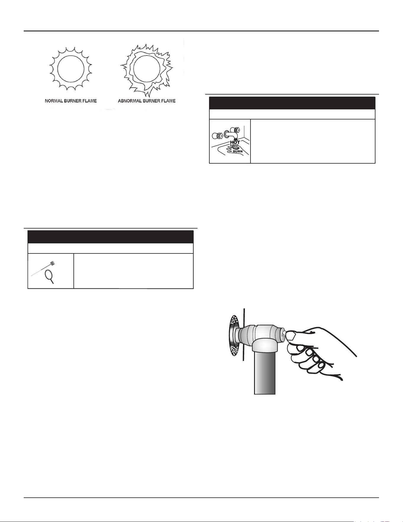
Maintenance
Residential Gas Water Heaters • 59
Figure 40. Normal and Abnormal Burner Flames
If the preceding burner characteristics are not evident, check for
accumulation of lint or other foreign material that restricts or blocks the
air intake fitting or air intake terminal.
To ensure continued good performance, keep the area around the water
heater clean and free from lint and debris. Sweep the floor around the
water heater regularly. This will reduce the dust and dirt which can enter
the burner and heat exchanger, causing improper combustion and sooting.
If the air intake fitting and air intake terminal are clear and the burner
continues to exhibit abnormal flames, contact a qualified service agency
or have a qualified service professional inspect and clean the burner.
ANODE ROD MAINTENANCE
CAUTION
Property Damage Hazard
Operating the water heater with depleted or
malfunctioning anodes can damage the water
heater.
Annual inspection and replacement of the anode
rod is required.
The water heaters covered in this manual are factory equipped with a
powered anode rod mounted in the top of the unit. Powered anode rods
are of a permanent design and do not need replacing unless damaged,
however, inspection and cleaning should be performed once a year.
To inspect the powered anode, do the following:
1. Turn off electrical supply and gas supply to the water heater.
2. Shut off the water supply and open a nearby hot water faucet to
depressurize the water tank.
3. Drain approximately 5 gallons of water from tank. See
Draining and
Flushing
(page 57) for proper procedures. Close drain valve.
4. Remove the wiring connection on the top of the powered anode.
5. Remove the powered anode by loosening the 3/4” NPT bushing that
forms the top of the anodes.
6. Remove the entire anode rod from the water heater for inspection.
• If undamaged and in working order, clean the anode rod with a
soft cloth and reinstall.
• If the anode needs to be replaced, obtain a new anode rod.
Apply Thread-sealer
®
tape or an approved pipe sealant on the
threads before installing the new powered anode rod.
Whether re-installing or replacing the powered anode rod, check for
any leaks and immediately correct if found.
7. Turn on water supply and open nearby hot water faucet to purge air
from water system.
8. Refill the water heater following the instructions for
Filling the Water
Heater
(page 39) .
9. Restart the water heater as directed in this manual.
TEMPERATURE-PRESSURE RELIEF VALVE TEST
⚠
DANGER
Burn Hazard
The discharge water from the temperature-pressure
relief valve is hot enough to cause burns.
Keep clear of the temperature-pressure relief valve
discharge outlet.
It is recommended that the Temperature-Pressure Relief Valve should be
checked to ensure that it is in operating condition every 6 months.
When checking the Temperature-Pressure Relief Valve operation, make
sure that (1) no one is in front of or around the outlet of the Temperature-
Pressure Relief Valve discharge line, and (2) that the water discharge will
not cause any property damage, as water may be extremely hot. Use care
when operating valve as the valve may be hot.
To check the temperature-pressure relief valve, lift the lever at the end
of the valve several times. See
Figure 41
. The valve should seat properly
and operate freely.
If after manually operating the valve, it fails to completely reset and
continues to release water, immediately close the cold water inlet to the
water heater and drain the water heater. See
Draining and Flushing
(page
57). Replace the Temperature-Pressure Relief Valve with a properly
rated/sized new one. See
Temperature-Pressure Relief Valve
(page 23)
for instructions on replacement.
Figure 41. Testing the Temperature-Pressure Relief Valve
If the Temperature-Pressure Relief Valve on the water heater weeps or
discharges periodically, this may be due to thermal expansion.
Note: Excessive water pressure is the most common cause of
Temperature-Pressure Relief Valve leakage. Excessive water system
pressure is most often caused by “thermal expansion” in a “closed
system.” See
Closed Water Systems
(page 22) and
Thermal
Expansion
(page 22). The Temperature-Pressure Relief Valve is
not intended for the constant relief of thermal expansion.
Temperature-Pressure Relief Valve leakage due to pressure build up in a
closed system that does not have a thermal expansion tank installed is
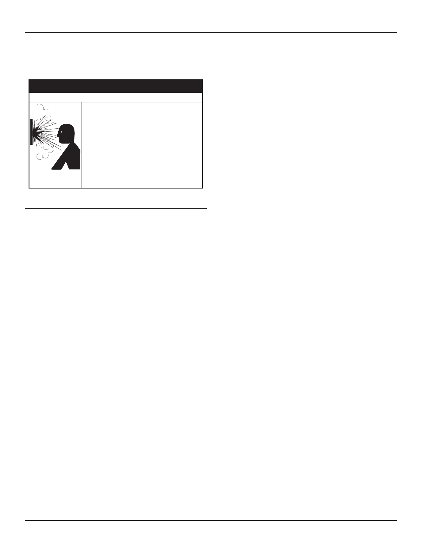
60 • Residential Gas Water Heaters
Maintenance
not covered under the limited warranty. Thermal expansion tanks must
be installed on all closed water systems.
Do not plug the Temperature-Pressure Relief Valve opening. This can
cause property damage, serious injury or death.
Normal opera�on of the water heater can cause
it to become sufficiently over-heated and/or
over-pressurized that it can explode, resul�ng in
property damage, sever injury, or death.
To avoid this hazard, you must install a properly-
sized temperature-pressure relief valve in opening
provided.
• The temperature-pressure relief valve must
comply with ANSI Z21.22-CSA 4.4 and ASME
code.
• Do not plug, block, or cap the discharge line.
⚠
WARNING
Explosion Hazard
SERVICE
If a condition persists or you are uncertain about the operation of the
water heater contact a qualified service technician.
Use this guide to check a leaking water heater. Many suspected leaks
are not leaking tanks. Often the source of the water can be found and
corrected.
If you are not thoroughly familiar with gas codes, your water heater, and
safety practices, contact your gas supplier or qualified installer to check
the water heater.
Read this manual first. Then before checking the water heater make sure
the gas supply has been turned “OFF”, and never turn the gas “ON” before
the tank is completely full of water.

Residential Gas Water Heaters • 61
TROUBLESHOOTING
INSTALLATION CHECKLIST
The list below represents some of the most critical installation requirements
that, when overlooked, often result in operational problems, down time
and needless parts replacement. This is not a complete list. Before
performing any troubleshooting procedures use the list below to check for
installation errors. Costs to correct installation errors are not covered under
the limited warranty. Ensure all installation requirements and instructions
in this manual have been maintained and followed.
Water Heater Location
1. Ensure proper clearances to combustibles are maintained and there is
sufficient room to service the water heater.
2. Ensure the area is free of corrosive elements and flammable materials.
Venting
3. Ensure the intake air and/or vent (exhaust) piping is the correct size
for the installed length.
4. Ensure the maximum equivalent length of pipe has not been exceeded
for the intake air and/or vent pipe.
5. Ensure the maximum number of elbows has not been exceeded in the
intake air and/or vent pipe.
6. Ensure all exterior clearances for the intake air, vent and concentric
terminations are maintained. These clearances and those cited by local
and national codes must be maintained.
7. If venting direct vent, ensure the screen located in air intake at the
water heater was removed.
Gas Supply And Piping
8. Ensure the supply gas line to each water heater meets the minimum
supply gas line size requirements.
Condensate Drain
9. Ensure the condensate drain is properly connected to the exhaust
elbow on the water heater and draining freely to a suitable floor drain.
Electrical Connections
10. Ensure the water heater is properly grounded. Flame sensing requires
an adequate earth ground. If the water heater is not properly grounded
it will cause Ignition Failure.
11. Ensure the power supply connections to the water heater are polarity
correct.
SEQUENCE OF OPERATION
Read the Sequence of Operation section before attempting to correct any
operational problems. See
Features and Components
(page 10) for the
location of various water heater components described in this section.
1. When the control system is powered (after initial calibration sequence),
during boot up, it will display water heater model information during
initialization. After a few moments the control system LCD Touch Display
which is part of the UIM (user interface module) will display the default
screen known as the “Home” screen.
2. If the control system determines that the actual water temperature
inside the tank is below the programmed Operating Set Point minus
the Differential setting, a heating cycle is activated.
3. The control system then performs selected diagnostic system checks.
This includes confirming the blocked exhaust, blocked intake and high-
temperature limit control (energy cut out) are not activated.
4. If all diagnostic checks are successfully passed, the control system
energizes the Combustion Blower for prepurge.
5. The control system energizes the Spark Ignition Transformer..
6. After a few seconds, the control system energizes the Gas Control Valve
allowing gas to flow to the Main Burner.
7. The control system monitors the flame sensor to confirm a flame is
present at the Main Burner. If a flame is not verified during the ignition
trial period the control system will try for ignition up to two more times.
If flame can not be verified after three trials for ignition, the control
system will lock out and display the “Ignition Failure” Fault message.
8. If a flame is verified, the control system will deenergize the Spark
Ignition Transformer and enter the heating mode where it will continue
heating the water until the Operating Set Point is reached. At this
point, the control system will deenergize the gas valve and enter the
post-purge cycle.
9. The Combustion Blower will run for the duration of the post purge cycle
to purge the water heater of all combustion gases. When the post-purge
cycle is complete, the blower is deenergized and will coast to a stop.
10. The control system now enters the standby mode while continuing
to monitor the internal storage tank water temperature and the state
of other system devices. If the tank temperature drops below the
Operating Set Point minus the Differential setting, the control will
automatically return to Step 2 and repeat the operating cycle.
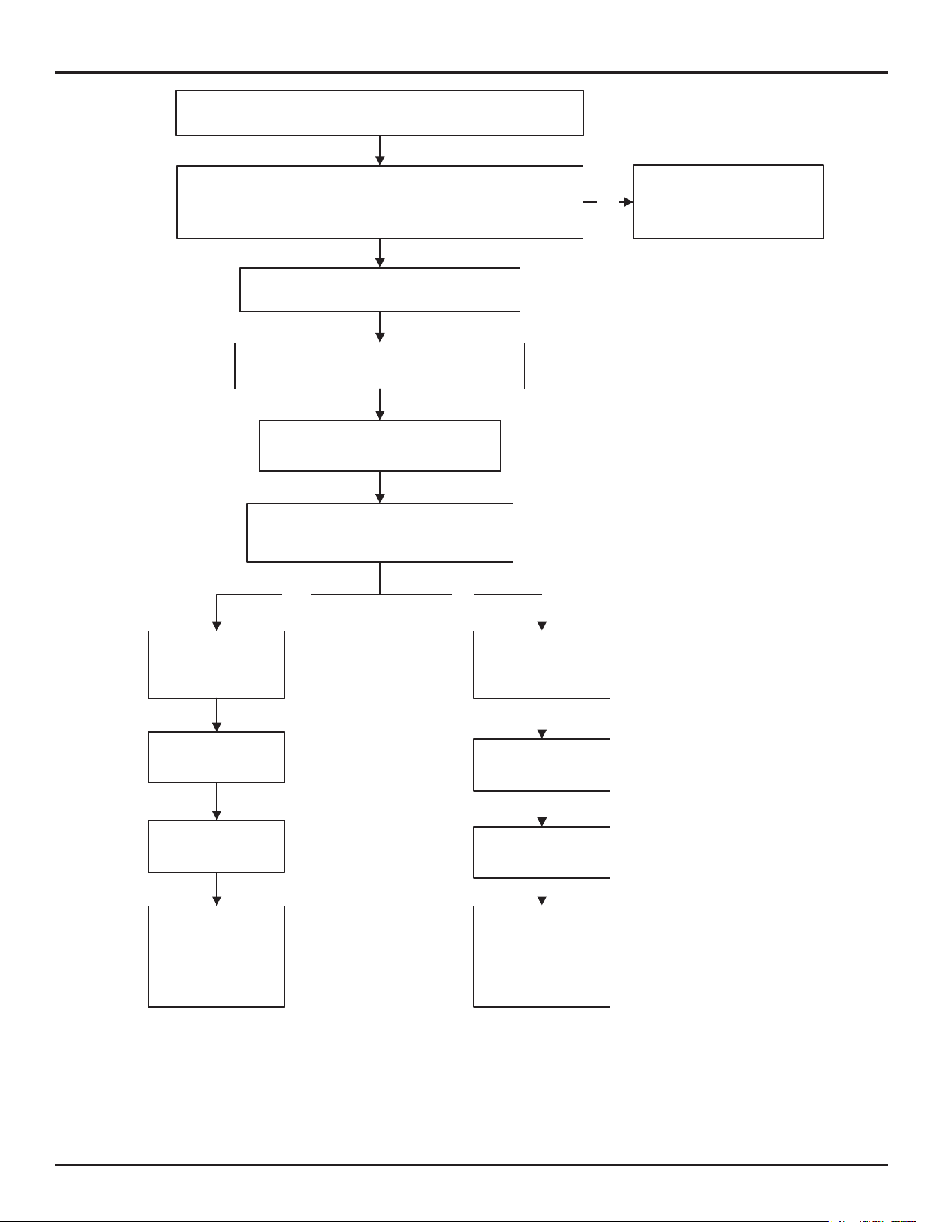
62 • Residential Gas Water Heaters
Troubleshooting
YES NO
Water is heated to
set point
Gas Valve
de-energized
Inter-Purge cycle
Gas Valve
de-energized
Retries up to
two more times
Post-Purge cycle
Control System
Locks Out
“Ignition Failure”
Fault Message is
displayed
Water heater goes
into standby mode
If tank temperature drops below Operating Set Point minus
Differential setting a heating cycle is activated
Spark Ignition Transformer is energized
Gas Valve is energized
gas flows to Main Burner
Is flame sensed at the Main Burner?
(control system monitors the flame sensor)
Control System Locks Out
Displays Fault Message
NO
Combustion Blower is energized
Pre-Purge cycle
Control System performs diagnostic checks
Normal State of all pressure switches and ECO are checked
Pressure switches and ECO are verified closed
Figure 42. Sequence of Operation
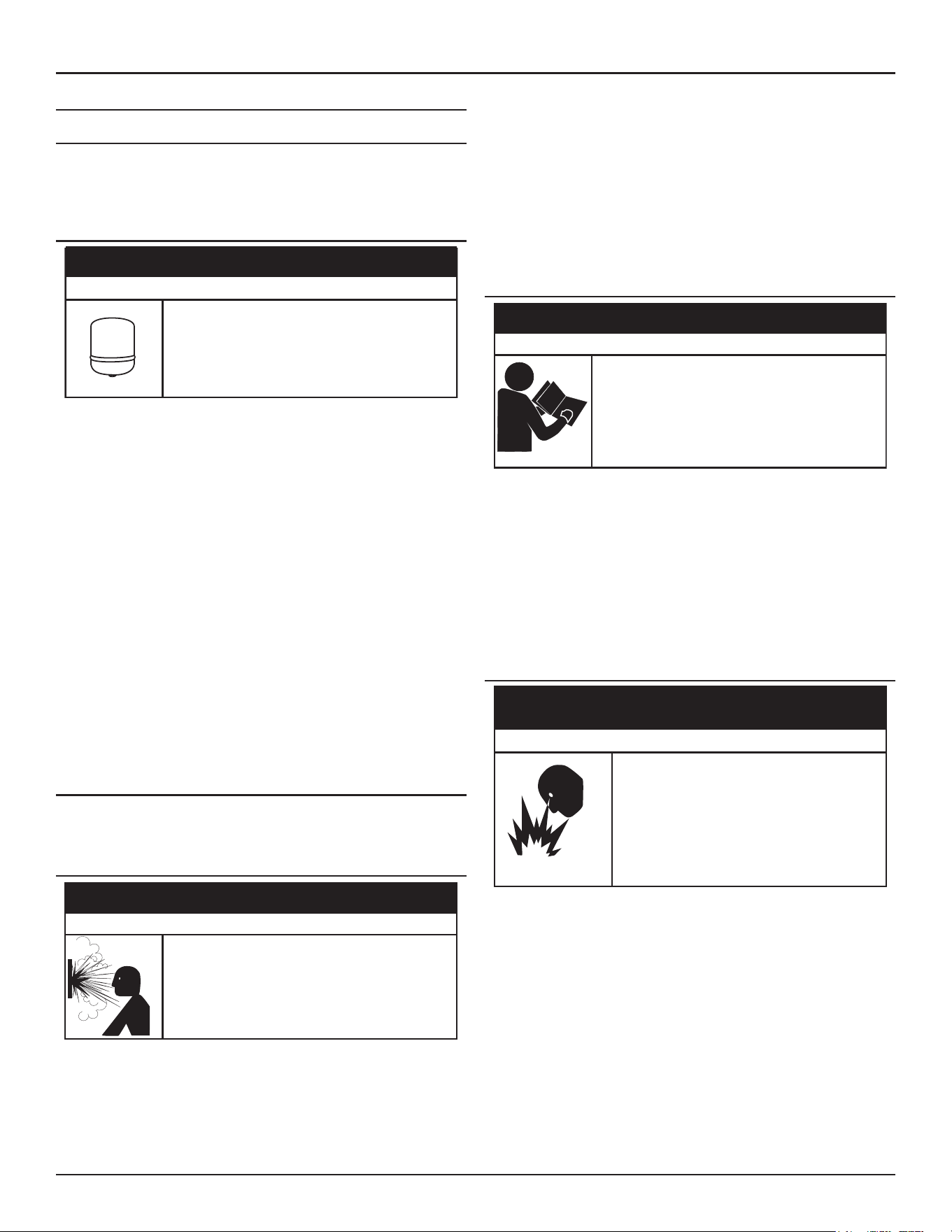
Troubleshooting
Residential Gas Water Heaters • 63
START UP CONDITIONS
Smoke/Odor
It is not uncommon to experience a small amount of smoke and odor during
the initial start-up. This is due to burning off of oil from metal parts, and
will disappear in a short while.
Thermal Expansion
CAUTION
Property Damage Hazard
Avoid water heater damage from pressure fluctua�ons
in closed water systems.
• Fill tank with water before operating.
• Install thermal expansion tank if necessary.
• Do not apply heat to cold water inlet.
• Contact qualified installer or service agency.
Water supply systems may, because of such events as high line pressure,
frequent cut-offs, the effects of water hammer among others, have
installed devices such as pressure reducing valves, check valves, back flow
preventers, etc. to control these types of problems. When these devices
are not equipped with an internal by pass, and no other measures are
taken, the devices cause the water system to be closed. As water is heated,
it expands (thermal expansion) and closed systems do not allow for the
expansion of heated water.
The water within the water tank expands as it is heated and increases the
pressure of the water system. If the relieving point of the water heater’s
temperature-pressure relief valve is reached, the valve will release excess
pressure. The temperature-pressure relief valve is not intended for the
constant relief of thermal expansion. This is an unacceptable condition
and must be corrected. It is recommended that any devices installed
which could create a closed system have a by-pass and/or the system
have an expansion tank or device to relieve the pressure built by thermal
expansion in the water system. Expansion tanks are available for ordering
through a local plumbing contractor. Contact the local water heater supplier
or qualified service agency for assistance in controlling these situations.
OPERATIONAL CONDITIONS
Do not remove the powered anode rod leaving the tank unprotected. By
doing so, all warranty on the water heater tank is voided.
Air In Hot Water Faucets
Flammable hydrogen gases can form in water pipes.
The hydrogen can explode if it is exposed to flame and
can cause severe injury or death.
Keep all igni�on sources away from faucet when
turning on hot water.
⚠
WARNING
Explosion Hazard
HYDROGEN GAS: Hydrogen gas can be produced in a hot water system
that has not been used for a long period of time (generally two weeks or
more). Hydrogen gas is extremely flammable and explosive. To prevent
the possibility of injury under these conditions, we recommend the hot
water faucet, located farthest away, be opened for several minutes before
any electrical appliances which are connected to the hot water system are
used (such as a dishwasher or washing machine). If hydrogen gas is present,
there will probably be an unusual sound similar to air escaping through
the pipe as the hot water faucet is opened. There must be no smoking or
open flame near the faucet at the time it is open.
OPERATIONAL PROBLEMS
Failure to follow these instrucons and safety
messages could result in death or serious injury.
Read and understand this instrucon manual and the
safety messages herein before installing, operang or
servicing this water heater.
This manual must remain with the water heater.
⚠
WARNING
Safety Hazard
This section of the manual is intended to be an aid in correcting common
operational problems, it is not all inclusive. The installer may be able to
observe and correct certain problems which might arise when the water
heater is first put into operation or when it is re-fired after a prolonged
shutdown. However, only qualified service technician should perform any
service procedures on the water heater.
Note: For technical support or to locate a qualified service technician in
your area, call the phone number on the warranty sheet supplied
with this water heater.
Rough Starting, Rough Operation
Fire and Explosion Hazard
An improper field conversion from one
type of gas to another could cause
potentially dangerous conditions that may
cause an explosion or fire resulting in
property damage, bodily injury or death.
Do not attempt to convert a water heater
without consulting A. O. Smith.
⚠
WARNING
• Undersized supply gas line (low volume of supply gas).
• Low Gas Pressure.
• Excessive supply gas pressure.
• Excessive manifold (offset) gas pressure.
• Incorrect Fuel Type
• Vent (exhaust) gas recirculation at the vent and intake air pipe
terminations on Direct Vent installations.
• Excessive equivalent lengths of intake air and/or vent (exhaust)
piping installed.
• Clogged/blocked intake air screen(s).
• Clogged/blocked the Main Burner.
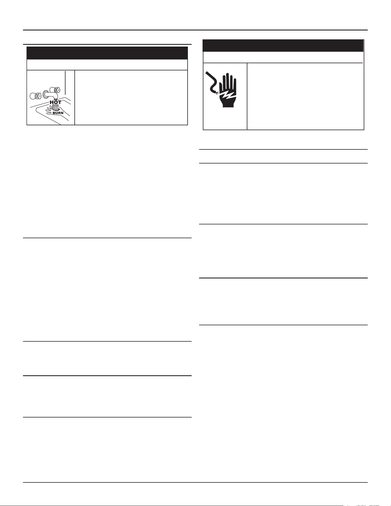
64 • Residential Gas Water Heaters
Troubleshooting
Momentary Ignition
• The combustion chamber and burner sleeve and
housing become very hot during operation.
• Do not reach into the burner housing or
combustion chamber if the water heater is still
hot.
• Allow the water heater to cool and always use
gloves when handling the main burner.
⚠
CAUTION
Burn Hazard
If the Main Burner ignites momentarily but does not sustain ignition, the
water heater will try to ignite up to two more times until control system
locks out and the Ignition Failure Fault message is displayed on the control
system's LCD. If the water heater is experiencing rough starts. See
Rough
Starting, Rough Operation
on this page. For momentary ignition problems
without rough starting check the following:
• Incorrect manifold (offset) gas pressure.
• Undersized supply gas line (low volume of supply gas).
• Low Gas Pressure
• See the list of possible causes and things to check and repair for the
Ignition Failure Fault message.
• Clogged/blocked intake air screen(s).
• Clogged/blocked Main Burner.
Not Enough Or No Hot Water
• No power to the water heater, check breaker, fuses.
• Enable/Disable switch in “disabled” position. Set to enable to allow
unit to operate.
• Hot water supply valve(s) to fixtures closed.
• Operating Set Point is set too low, Differential setting is set too high.
• The heating capacity of the water heater has been exceeded, the
water heater is unable to meet demand.
• Colder incoming water temperature lengthening the time required
to heat water to desired temperature.
• Hot water piping leaks, open faucets, water heater drain valve
leaking or open.
• Sediment or lime scale accumulation may be affecting water heater
operation.
Water Is Too Hot
• Operating Set Point is set too high.
• If installed check thermostatic point-of-use mixing valve settings.
• Lime build-up on temperature probe. Inspect and clean.
Noisy Operation
• Normal operating noise of electrical components; Combustion
Blower, transformer hum, relay contact closure, or incorrect venting
configuration
REPLACEMENT PARTS
Replacement parts may be ordered from the manufacturer, authorized
service agencies or distributors. When ordering parts be sure to have the
complete water heater Model Number, Serial Number and Series Number
available. This information can be found on the rating plate affixed to the
water heater.
For more information or technical support call the phone number on the
warranty sheet supplied with this water heater.
Servicing this water heater exposes you to
electrified components that can cause severe
injury or death if you touch them.
• Turn off power at the branch circuit breaker
serving the water heater before performing any
service.
• Label all wires prior to disconnecting when
performing service. Wiring errors can cause
improper and dangerous operation.
• Verify proper operation after servicing.
⚠
WARNING
Electrical Shock Hazard
FAULT AND ALERT CONDITIONS
Fault Conditions
When the control system declares a Fault condition it will display a Fault
message on the control system's LCD with an exclamation "!" mark. For
soft faults, the system will try to reset in 15 minutes or the system can
reset the heater enable switch immediately. The water heater must be
serviced by a qualified service technician before operation can be restored
for some fault conditions.
Alert Conditions
When the control system declares an Alert condition it will display an
Alert message on the control system's LCD with a question "?" mark. The
water heater will continue to operate during an Alert condition but the
water heater must be serviced by a qualified service technician as soon
as possible.
Resetting Control System Lock Outs
To reset the control system from a lock out condition, turn off the switch
in front of the unit for approximately 20 seconds and then back on. Keep
in mind that if the condition that caused the Fault has not been corrected,
the control system will continue to lock out.
Diagnostic Checks
The following section, Fault And Alert Messages lists some of the messages
the control system will display on the LCD when there are operational
problems. This is not a complete list. Along with each of the Fault and
Alert messages described there will be a list of possible causes and things
to check and repair. In addition, each fault/alert code has advanced text
to further detail the issue. This can be accessed by tapping the “More”
button on the fault/alert screen.
Only qualified service technician, as defined in Qualifications using
appropriate test equipment, should perform any service procedures on
the water heater.
Note: If you are not qualified and licensed or certified as required by the
authority having jurisdiction to perform a given task do not attempt
to perform any of the diagnostic or service procedures described
in the following section.
If you do not understand the instructions in the following section do not
attempt to perform any procedures.
Call the technical support phone number listed on the water heater
labeling for further technical assistance or to locate a qualified service
technician in your area.
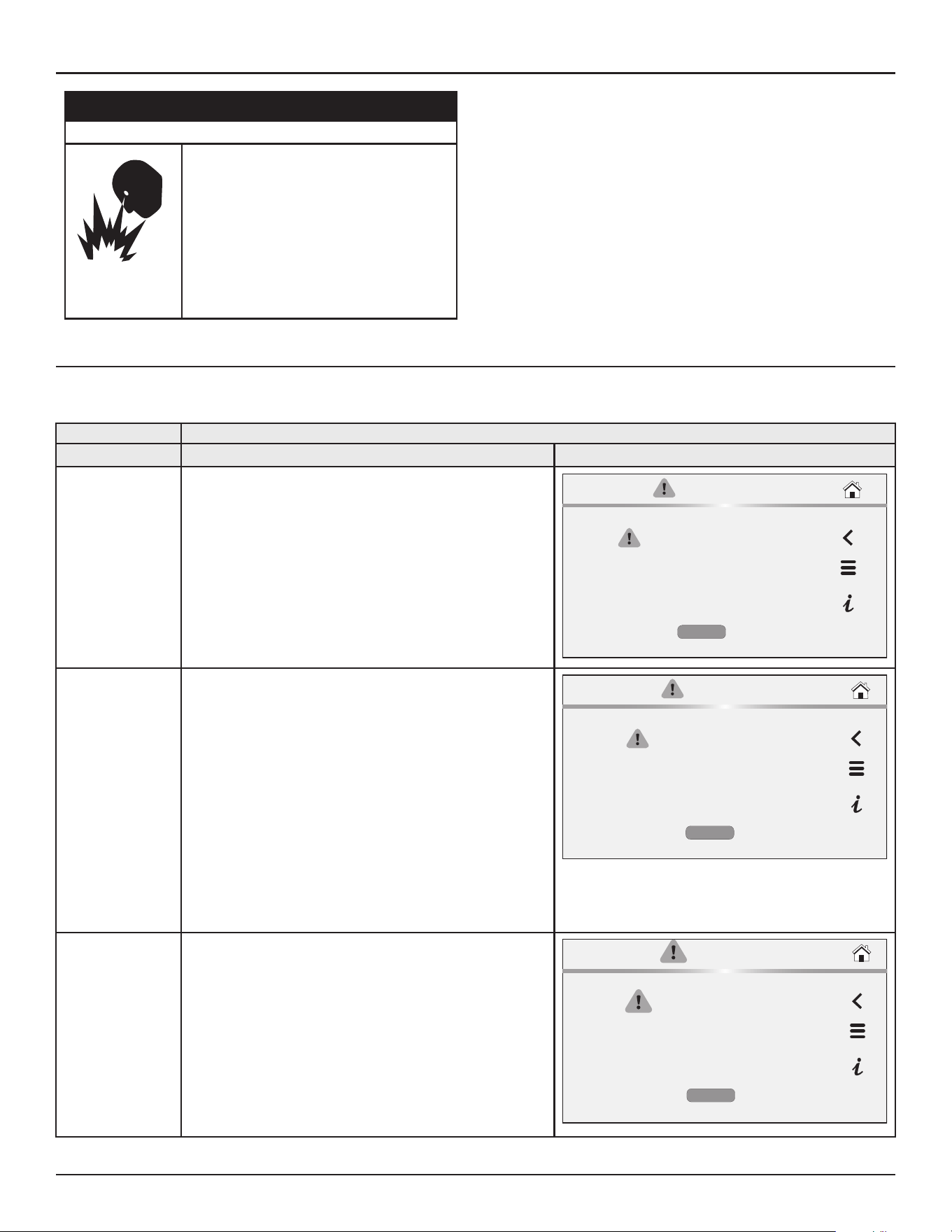
Troubleshooting
Residential Gas Water Heaters • 65
Jumping out control circuits or components can
result in property damage, personal injury or death.
• Service should only be performed by a qualified
service technician using proper test equipment.
• Altering the water heater controls and/or wiring in
any way could result in permanent damage to the
controls or water heater and is not covered under
the limited warranty.
• Any bypass or alteration of the water heater
controls and/or wiring will result in voiding the
appl
iance warranty.
⚠
WARNING
Safety Hazard
Fault and Alert Messages
Contact Technical Support for further assistance or to locate a qualified service agent in your area. See the contact-information label on the water heater.
Fault and Alert Messages
FAULT CODE Possible Causes - Check/Repair
Displayed Fault/Alert Message
2
Data Error Code:
(3, 30) NTC A short
(3, 31) NTC A open
(3, 32) NTC B short
(3, 33) NTC B open
(3,1001) NTC C open
(3,1002) NTC C short
(3,1018) NTC drift
High Temp Limit Exceeded
The water heater is shut down due to high tank temperature.
The water temperature in the tank has exceeded the high
temperature limit.
1. Use a thermometer at a hot water fixture to confirm the
actual water temperature. If temperature is below 180˚
reset water heater.
2. If problem continues, contact technical support or refer to
the service handbook for further instructions.
CURRENT FAULT
High Temp Limit Exceeded
Occurred:
04/28/2025 12:34 AM
The water heater is shut down due to high
tank temperature.
MORE
3
Data Error Code:
30;31;
32;33
Main Temperature Probe Failure
The indicated temperature probe might be shorted or open.
The control system has detected an issue with the main
temperature probe.
1. Ensure the wire connections for the main temp probe are
clean and secure.
2. Ensure the wire harness for the main temp probe is free
from damages.
3. If the problem continues, contact technical support or refer
to the service handbook for further instructions.
Note: If there are both main and lower temperature probes, the
Main Temperature probe is the main temperature probe.
CURRENT FAULT
Main Temperature Probe Failure
Occurred:
04/28/2025 12:34 AM
The indicated temperature probe might be
shorted or open.
MORE
5
Data Error Code:
(3,10xx) where xx =
5,9,13 or 17
Software Failure
Internal control failures are detected on TRC. Cycle power to the
water heater.
The controls system has detected a software issue.
1. Cycle the main power supply to the water heater by turning
off the breaker/disconnect, then wait approximately 30
seconds and turn main power supply back on.
2. If problem continues, contact Technical Support or refer to
the service handbook for further instructions.
CURRENT FAULT
Software Failure
Occurred:
04/28/2020 12:34 AM
Internal control failures are detected on
TRC. Cycle power to the water heater.
MORE
66 • Residential Gas Water Heaters
Troubleshooting
Fault and Alert Messages
FAULT CODE Possible Causes - Check/Repair
Displayed Fault/Alert Message
6
(6,10xx) where xx =
4, 8, 12 or 16
OR
(6,80xx) where xx
= 1-10
Hardware Failure
Internal control failures are detected on the TRC. Cycle power to
the water heater.
The controls system has detected a hardware issue.
1. Cycle the main power supply to the water heater by turning
off the breaker/disconnect, then wait approximately 30
seconds and turn main power supply back on.
2. If problem continues, contact Technical Support or refer to
the service handbook for further instructions.
CURRENT FAULT
Hardware Failure
Occurred:
04/28/2025 12:34 AM
Internal control failures are detected on the
TRC. Cycle power to the water heater.
MORE
9
Data Error Code: 22
Power Supply Fault
The Control System is detecting a problem with the incoming
power supply.
1. Cycle the main power supply to the heater by turning
off the breaker/disconnect, then wait approximately 30
seconds and turn main power supply back on.
2. If problem continues, contact technical support or refer to
the service handbook for further instructions.
CURRENT FAULT
Power Supply Fault
Occurred:
04/28/2025 12:34 AM
The Control System is detecting a problem
with the incoming power supply.
MORE
20
Data Error Code:
(20,0)
Communication Failure
Communications between the display and the TRC is lost.
The control system has lost communications with UIM.
1. Cycle the main power supply to the heater by turning
off the breaker/disconnect, then wait approximately 30
seconds and turn main power supply back on.
2. Inspect the communication cable between the UIM and
the TRC to ensure the cable is not damaged and the
connections are clean and secure.
3. If problem continues, contact technical support, or refer to
the service handbook for further instructions.
CURRENT FAULT
Communication Failure
Occurred:
04/28/2025 12:34 AM
Communications between the display and
the TRC is lost.
MORE
25
Data Error Code:
(4,1010) NTC open
(4,1011) NTC short
Flue Gas Temperature Probe Failure
The flue gas temperature probe might be shorted or open.
The control system has detected an issue with the flue gas
temperature probe.
1. Cycle the main power supply to the heater by turning
off the breaker/disconnect, then wait approximately 30
seconds and turn main power supply back on.
2. If problem continues, contact technical support for further
instructions.
CURRENT FAULT
Flue Gas Temperature
Probe Failure
Occurred:
04/28/2025 12:34 AM
The flue gas temperature probe might be
shorted or open.
MORE
Troubleshooting
Residential Gas Water Heaters • 67
Fault and Alert Messages
FAULT CODE Possible Causes - Check/Repair
Displayed Fault/Alert Message
31
Data Error Code:
(31,7002) or
(31, 7003) or
(31, 7004)
Water Leak Detected
A water leak or other water-present condition is being detected.
Check for a leak or other water problem at the water sensor.
The control system has detected a leak near the heater.
1. Inspect the area around the heater for signs of moisture.
2. Inspect all threaded fittings connected to the water heater
for signs of moisture.
3. Inspect the exhaust elbow connection to the heater for
signs of moisture.
4. Inspect the clean-out cover for signs of moisture.
5. Using litmus strips for pH testing to identify if the moisture
is condensate or water from the tank.
6. Condensation from the exhaust will be highly acidic.
7. If problem continues, contact technical support for further
instructions.
CURRENT FAULT
Water Leak Detected
Occurred:
04/28/2025 12:34 AM
A water leak or other water-present
condition is being detected. Check for a leak
or other water problem at the water sensor.
MORE
32
Data Error Code:
(32, 7001)
Leak Sensor Disconnected
The leak sensor is no longer being detected by the controller.
The control system has detected that the leak detector has been
disconnected.
1. Ensure the leak detector is securely connected to the water
heater.
2. Ensure the leak detector harness is securely connected to
the TRC at terminal J6 pins 1 and 11.
3. If problem continues, contact technical support for further
instructions.
CURRENT FAULT
Leak Sensor Disconnected
Occurred:
04/28/2025 12:34 AM
The leak sensor is no longer being detected
by the controller.
MORE
33
Data Error Code:
(33, 60x7) where
x = 0 is on TRC-1000
board anode circuit.
x = 1 is CPAM 1,
x = 2 is CPAM 2 etc.
Anode Shorted
The powered anode is shorted to earth ground or to the tank.
The Control System has detected that the anode rod has shortage
to the tank.
1. Inspect anode wire connection for corrosion, moisture, or
other contaminates.
2. Ensure wire connection on both ends is secure.
3. Ensure anode wire harness is not damaged.
4. If problem continues, contact technical support for further
instructions.
CURRENT FAULT
Anode Shorted
Occurred:
04/28/2025 12:34 AM
The powered anode is shorted to earth
ground or to the tank.
MORE
68 • Residential Gas Water Heaters
Troubleshooting
Fault and Alert Messages
FAULT CODE Possible Causes - Check/Repair
Displayed Fault/Alert Message
34
Data Error Code:
(34, 60x4) where
x = 0 is on TRC-1000
board anode circuit.
x = 1 is CPAM 1,
x = 2 is CPAM 2 etc.
No Water
No water is detected by the powered anode.
The Control System is not detecting water in the tank.
1. Ensure there is water in the tank by following Fill the Tank
Instructions found in the installation manual.
2. Inspect anode wire connection for corrosion, moisture, or
other contaminates.
3. Ensure wire connection on both ends is secure.
4. Ensure anode wire harness is not damaged.
5. If problem continues, contact technical support for further
instructions.
CURRENT FAULT
No Water
Occurred:
04/28/2025 12:34 AM
No water is detected by the powered anode.
MORE
36
Data Error Code: 244
(36, 2440x)
x = 1 to 9 are reason
codes.
Weak Flame Signal
The Combustion Safety Control (CSC) is detecting low-flame
generated current.
The control system has detected a weak flame signal
1. Ensure that the flame sensor wire harness is free of
damages
2. Ensure that the flame sensor wire connection on both ends
is secure and free of contaminates
3. Remove flame sensor and inspect for contaminates or
damages in ceramic insulator
4. Clean flame sensor rod with steel wool
5. If the problem continues, contact technical support, or refer
to the service handbook for further instructions
CURRENT FAULT
Weak Flame Signal
Occurred:
04/28/2025 12:34 AM
The Combustion Safety Control (CSC) is
detecting low-flame generated current.
MORE
37
Data Error Code:
2, 130
(37, 2)
Or
(37, 130)
Flame Sensor Error
The control system has detected a flame sensor error.
The flame-sense rod is detecting a flame signal when the gas valve
is supposed to be off.
The control system has detected a flame sensor error.
1. Ensure that the flame sensor wire harness is free of
damages.
2. Ensure that the flame sensor wire connection on both ends
is secure and free of contaminates.
3. Remove flame sensor and inspect for contaminates or
damages in ceramic insulator.
4. Clean flame sensor rod with steel wool.
5. If the problem continues, contact technical support, or refer
to the service handbook for further instructions.
CURRENT FAULT
Flame Sensor Sensing Error
Occurred:
04/28/2025 12:34 AM
The control system has detected a flame
sensor error.
MORE
Troubleshooting
Residential Gas Water Heaters • 69
Fault and Alert Messages
FAULT CODE Possible Causes - Check/Repair
Displayed Fault/Alert Message
38
(Resideo 129, 147,
241)
or 38
Data Error Code:
(38, 129) or
(38, 147) or
(38, 241) or
(38, 38)
Ignition Failure
The control system failed to sense a flame signal during the
ignition sequence.
The control system failed to sense a flame signal during the
ignition sequence
1. Verify that the gas supply, venting, and intake air pipes are
installed according to the instruction manual provided with
the water heater.
2. If the problem continues, contact technical support, or refer
to the service handbook for further instructions.
CURRENT FAULTCURRENT FAULT
CURRENT FAULT
Ignition Failure
Occurred:
04/28/2025 12:34 AM
The control system failed to sense a flame
signal during the ignition sequence.
MORE
41
Data Error Code:
(41, 1003)
High Temperature Warning
The main temperature probe exceeds 190°F.
The water temperature in the tank has exceeded the high
temperature warning temperature. The warning will reset when
tank temperature drops below 180°F.
1. Reset the water heater by toggling the Enable/Disable
switch to disable and back to enable.
2. If the problem continues, use a thermometer at a hot water
fixture to confirm the water temperature.
3. If the problem continues, contact technical support or refer
to the service handbook for further instructions.
CURRENT FAULT
CURRENT FAULT
CURRENT FAULT
Temp High Limit
Occurred:
04/28/2025 12:34 AM
The primary temperature exceeds the
high-limit setpoint.
MORE
42
Clock Not Set
Clock (time and date) are not set.
Check the iComm connection (if equipped) and reconnect for
automatic calendar updates.
The control system recognized that the clock is not set.
1. Refer to the installation manual for instructions on how to
set the clock.
2. If the problem continues, contact technical support for
further instructions.
CURRENT FAULT
CURRENT FAULT
CURRENT FAULT
Clock Not Set
Occurred:
09/08/2020 12:34 AM
Clock (time and date) are not set.
MORE
70 • Residential Gas Water Heaters
Troubleshooting
Fault and Alert Messages
FAULT CODE Possible Causes - Check/Repair
Displayed Fault/Alert Message
201
Data Error Code: 71
(201, 71)
Blocked Air Intake
There is a restriction in the air intake. Check the intake pipe and
termination for blockage.
The control system has detected a blockage in the intake air pipe.
1. Ensure that the intake air pipe installed according to the
manufacturer’s installation manual.
2. Ensure that all horizontal pipe runs are properly sloped to
prevent moisture from accumulating and restricting air flow.
3. Inspect the inside of the intake air pipe from the connection
at the blower, all the way to the outside termination for
restrictions.
4. Inspect the plastic sensing tube to the blocked intake air
pressure switch to ensure there are no restrictions.
5. Ensure the blocked intake air pressure switch wires are free
from damages and contaminates.
6. Ensure wire connections are secure and free from
contaminates.
7. If problem continues, contact technical support, or refer to
the service handbook for further instructions.
CURRENT FAULTCURRENT FAULT
CURRENT FAULT
Blocked Air Intake
Occurred:
04/28/2025 12:34 AM
There is a restriction in the air intake. Check
the intake pipe and termination for
blockage.
MORE
202
Data Error Code: 70
(202, 70)
Blocked Exhaust
There is a restriction in exhaust pipe. Check exhaust pipe and
termination for blockage.
The control system has detected a blockage in the exhaust vent
pipe.
1. Ensure that the exhaust vent pipe installed according to the
manufacturer’s installation manual.
2. Ensure that all horizontal pipe runs are properly sloped to
prevent moisture from accumulating and restricting air flow.
3. Inspect the inside of the exhaust vent pipe from the water
heater connection all the way to the outside termination for
restrictions.
4. Inspect the plastic sensing tube to the blocked exhaust
pressure switch to ensure there are no restrictions.
5. Ensure the blocked exhaust pressure switch wires are free
from damages and contaminates.
6. Ensure wire connections are secure and free from
contaminates.
7. If problem continues, contact technical support, or refer to
the service handbook for further instructions.
CURRENT FAULT
Blocked Exhaust
Occurred:
04/28/2025 12:34 AM
There is a restriction in exhaust pipe. Check
exhaust pipe and termination for blockage.
MORE
205
Data Error Code:
(205,200x)
Where:
x =2 if the key is
uninitialized
x=3 if key
configuration is
corrupt.
Software and FMM Incompatible
The TRC version is older than the TRC version stored in key.
The control system has detected a device that is incompatible
1. Contact Technical Support for further instructions.
CURRENT FAULT
Software and FMM Key Incompatible
Occurred:
04/28/2025 12:34 AM
The TRC version is older than the TRC
version stored in key.
MORE
Troubleshooting
Residential Gas Water Heaters • 71
Fault and Alert Messages
FAULT CODE Possible Causes - Check/Repair
Displayed Fault/Alert Message
206
Data Error Code:
(206, 2011)
CPAM Disconnected
Communication with the anode module has been lost.
The control system has detected that the CPAM is disconnected
1. Ensure CPAM is powered
2. Ensure wire connections are secure and free of
contaminates
3. Ensure wire harness is free of damages
4. If problem continues, contact technical support or refer to
the service handbook for further instructions
CURRENT FAULT
CPAM Disconnected
Occurred:
04/28/2025 12:34 AM
Communication with the anode module has
been lost.
MORE
207
Data Error Code:
(207, 35)
CSC Disconnected
Communication with the Combustion Safety control (CSC) has
been lost.
The CSC is disconnected
1. Ensure the communication cable is securely connected
between the TRC on terminal J4 and the CSC on terminal
X10.
2. If problem continues, contact technical support or refer to
the service handbook for further instructions.
CURRENT FAULT
CSC Disconnected
Occurred:
04/28/2025 12:34 AM
Communication with the anode module has
been lost.
MORE
209
Data Error Code:
(209, 2013)
Water Valve Module Disconnected
Communication with the water valve module has been lost.
The control system has detected that the Valve Module is
disconnected.
1. Ensure Valve module is powered.
2. Ensure wire connections are secure and free of
contaminates.
3. Ensure wire harness is free of damages.
4. If problem continues, contact technical support or refer to
the service handbook for further instructions.
CURRENT FAULT
Water Valve Module Disconnected
Occurred:
04/28/2024 12:34 AM
Communication with the water valve module
has been lost.
MORE
210
Data Error Code:
(210, 35)
Auto Test Complete
Cycle Main Power to water heater. If problem continues, contact
technical support for further instructions.
CURRENT FAULT
Auto Test Complete/Passed
Occurred:
04/28/2025 12:34 AM
No action required.
MORE
72 • Residential Gas Water Heaters
Troubleshooting
Fault and Alert Messages
FAULT CODE Possible Causes - Check/Repair
Displayed Fault/Alert Message
211
Data Error Code:
(211, 133)
No Blower Speed Feedback
The control system has not detected the correct feedback from
the blower when a command was sent to the blower to operate.
1. Ensure both wire connections to the blower and to the
control system is secure and free of contaminates
2. Ensure the wire harnesses are free from damages
3. If problem continue, contact technical support, or refer to
the service handbook for further instructions.
CURRENT FAULT
No Blower Speed Feedback
Occurred:
04/28/2025 12:34 AM
The control system has detected an issue
with the main temperature probe.
MORE
212
Data Error Code:
(212, xxx) where xxx -
142, 143,
144 or 146
Main Temperature Probe Failure
The control system has detected an issue with the main
temperature probe.
The control system has detected an issue with the main
temperature probe.
1. Ensure the wire connections for the main temp probe are
clean and secure.
2. Ensure the wire harness for the main temp probe is free
from damages.
3. If the problem continues, contact technical support or refer
to the service handbook for further instructions.
CURRENT FAULT
Main Temperature Probe Failure
Occurred:
04/28/2025 12:34 AM
The control system has detected an issue
with the main temperature probe.
MORE
213
Data Error Code:
(213, 136) or
(213, 243)
Hardware Failure
The control system has detected a flame sensor error.
1. Ensure that the flame sensor wire harness is free of
damages.
2. Ensure that the flame sensor wire connection on both ends
is secure and free of contaminates.
3. Remove flame sensor and inspect for contaminates or
damages in ceramic insulator.
4. Clean flame sensor rod with steel wool.
5. If the problem continues, contact technical support, or refer
to the service handbook for further instructions.
CURRENT FAULT
Hardware Failure
Occurred:
04/28/2025 12:34 AM
The control system has detected a flame
sensor error.
MORE
214
Data Error Code:
(214, xxx) where xxx
=149, 153, 155 or 157
Software Failure
The CSC has detected a software issue.
1. Cycle the main power supply to the water heater by turning
off the breaker/disconnect, then wait approximately 30
seconds and turn main power supply back on.
2. If problem continues, contact Technical Support or refer to
the service handbook for further instructions.
CURRENT FAULT
Software Failure
Occurred:
04/28/2025 12:34 AM
The CSC has detected a software issue.
MORE
Troubleshooting
Residential Gas Water Heaters • 73
Fault and Alert Messages
FAULT CODE Possible Causes - Check/Repair
Displayed Fault/Alert Message
215
Data Error Code:
(215, 2400x) where
x is the failed
calibration reason
described in the
service handbook.
Calibration Error
The CSC has detected a calibration error.
1. The CSC has detected a software issue.
2. Cycle the main power supply to the water heater by turning
off the breaker/disconnect, then wait approximately 30
seconds and turn main power supply back on.
3. If problem continues, contact Technical Support or refer to
the service handbook for further instructions.
CURRENT FAULT
Calibration Error
Occurred:
04/28/2025 12:34 AM
The CSC has detected a calibration error.
MORE
216
Data Error Code:
(216, 137)
Gas Valve Circuit Fault
The control system has detected a fault with the Gas Valve Circuit.
1. Ensure wire connections on both ends are secure and free
of contaminates.
2. Ensure wire harness is not damaged.
3. If problem continues, contact technical support, or refer to
the service handbook for further instructions.
CURRENT FAULT
Gas Valve Circuit Fault
Occurred:
04/28/2025 12:34 AM
The control system has detected a fault with
the Gas Valve Circuit.
MORE
217
Data Error Code:
(217, 242)
MDT Fault
The control system has detected a fault with the Motor Driven
Throttle (MDT).
1. Ensure wire connections on both ends are secure and free
of contaminates.
2. Ensure wire harness is not damaged.
3. If problem continues, contact technical support, or refer to
the service handbook for further instructions.
CURRENT FAULT
MDT Fault
Occurred:
04/28/2025 12:34 AM
The control system has detected a fault with
the Motor Driven Throttle (MDT).
MORE
218
Data Error Code:
(209, 2014)
BMS Module Disconnected
Communication with the BMS module has been lost.
The control system has detected that the BMS is disconnected.
1. Ensure BMS module is powered.
2. Ensure wire connections are secure and free of
contaminates.
3. Ensure wire harness is free of damages.
4. If problem continues, contact technical support or refer to
the service handbook for further instructions.
CURRENT FAULT
BMS Module Disconnected
Occurred:
04/28/2025 12:34 AM
Communication with the BMS module has
been lost.
MORE
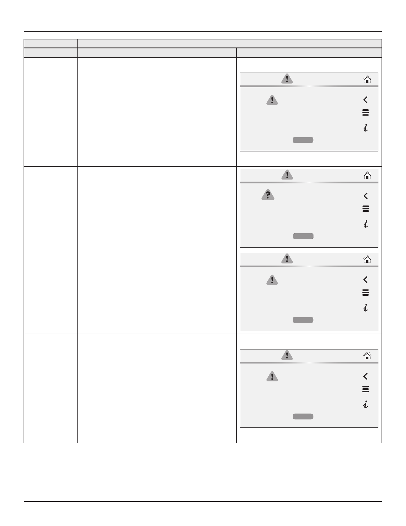
74 • Residential Gas Water Heaters
Troubleshooting
Fault and Alert Messages
FAULT CODE Possible Causes - Check/Repair
Displayed Fault/Alert Message
219
Anode Shorted
The central control board (TRC) is detecting low-resistance or a
short to earth ground or the tank.
Possible Causes:
1. Water at anode area.
2. Contamination (solder, Loctite, WD40 etc.) between the
anode top and the surrounding metal.
3. Sediment build up with a possible bridge to tank.
4. A loose anode wire touching the tank.
5. A bent anode shorting to the tank or an element.
CURRENT FAULT
Anode Shorted
Occurred:
04/28/2025 12:34 AM
The external powered anode circuit is
shorted to earth ground or the tank.
MORE
220
Powered Anode Module Failure
Cycle the main power to the unit off and then on.
The commercial power anode module (CPAM) needs to be
replaced.
CURRENT FAULT
Power Anode Module failure
Occurred:
09/08/2020 12:34 AM
The external powered anode circuit has a
failure.
MORE
221
Data Error Code:
13
Reset Lockout
The control system has detected a Reset Lockout
1. Cycle the main power to the water heater.
2. If problem continues, contact technical support, or refer to
the service handbook for further instructions.
CURRENT FAULT
Reset Lockout
Occurred:
04/28/2025 12:34 AM
The Combustion Safety control (CSC)
detected more than 5 resets within 15
minutes.
MORE
222
Data Error Code:
(222, 2001)
FMM Missing
The control system has detected that the Flex Memory Module
(FMM) is either missing or disconnected.
1. Ensure the wire connections are secure and free of
contaminates.
2. Ensure wire connection at terminal J2 on the TRC is
secure.
3. Ensure all wire harnesses are free from damages.
4. Cycle the main power to the water heater.
5. If problem continues, contact technical support for further
instructions.
CURRENT FAULT
FMM Missing
Occurred:
04/28/2025 12:34
The control system has detected that the
Flex Memory Module (FMM) is either
missing or disconnected.
MORE

Troubleshooting
Residential Gas Water Heaters • 75
Fault and Alert Messages
FAULT CODE Possible Causes - Check/Repair
Displayed Fault/Alert Message
223
Data Error Code:
(223, 2006)
Missing Display
The display was found to be missing.
The control system has detected that the User Interface Module
(UIM) is either missing or disconnected.
1. Ensure the wire connections are secure and free of
contaminates.
2. Ensure wire connection at terminal J2 on the TRC is
secure.
3. Ensure all wire harnesses are free from damages.
4. Cycle the main power to the water heater.
5. If problem continues, contact technical support for further
instructions.
CURRENT FAULT
Missing Display
Occurred:
04/28/2025 12:34
The control system has detected that the
Flex Memory Module (FMM) is either
missing or disconnected.
MORE
224
Data Error Code:
(224, 2005)
TRC Software or Hardware Is Old
The control system has detected that the Software or Hardware
Version on the TRC is outdated.
The control system has detected that the Software or Hardware
Version on the TRC is outdated.
1. Typically caused by replacing control system components
with an older revision software.
2. Contact technical support for further instructions.
CURRENT FAULT
TRC Software or Hardware Is Old
Occurred:
04/28/2025 12:34 AM
The control system has detected that the
Software or Hardware Version on the TRC is
outdated.
MORE
225
(225, 2007)
Display software or hardware is old.
The control system has detected that the Software Hardware
Version on the UIM is outdated.
1. Typically caused by replacing control system components
with an older revision software.
2. Contact technical support for further instructions.
CURRENT FAULT
Display software or hardware is old.
Occurred:
04/28/2025 12:34 AM
The control system has detected that the
Software Hardware Version on the UIM is
outdated
MORE
226
(226, 60xy)
where
x = 0 is on TRC-1000
board anode circuit.
x = 1 is CPAM 1,
x = 2 is CPAM 2 etc.
y = 1, 2, 3, 5, 6 or 8)
Powered Anode Circuit Failure
The control system has detected a failure with the Powered
Anode Circuit.
1. Cycle main power to the water heater.
2. Contact technical support for further instructions.
CURRENT FAULT
Powered Anode Circuit Failure
Occurred:
04/28/2025 12:34
The control system has detected a failure
with the Powered Anode Circuit.
MORE
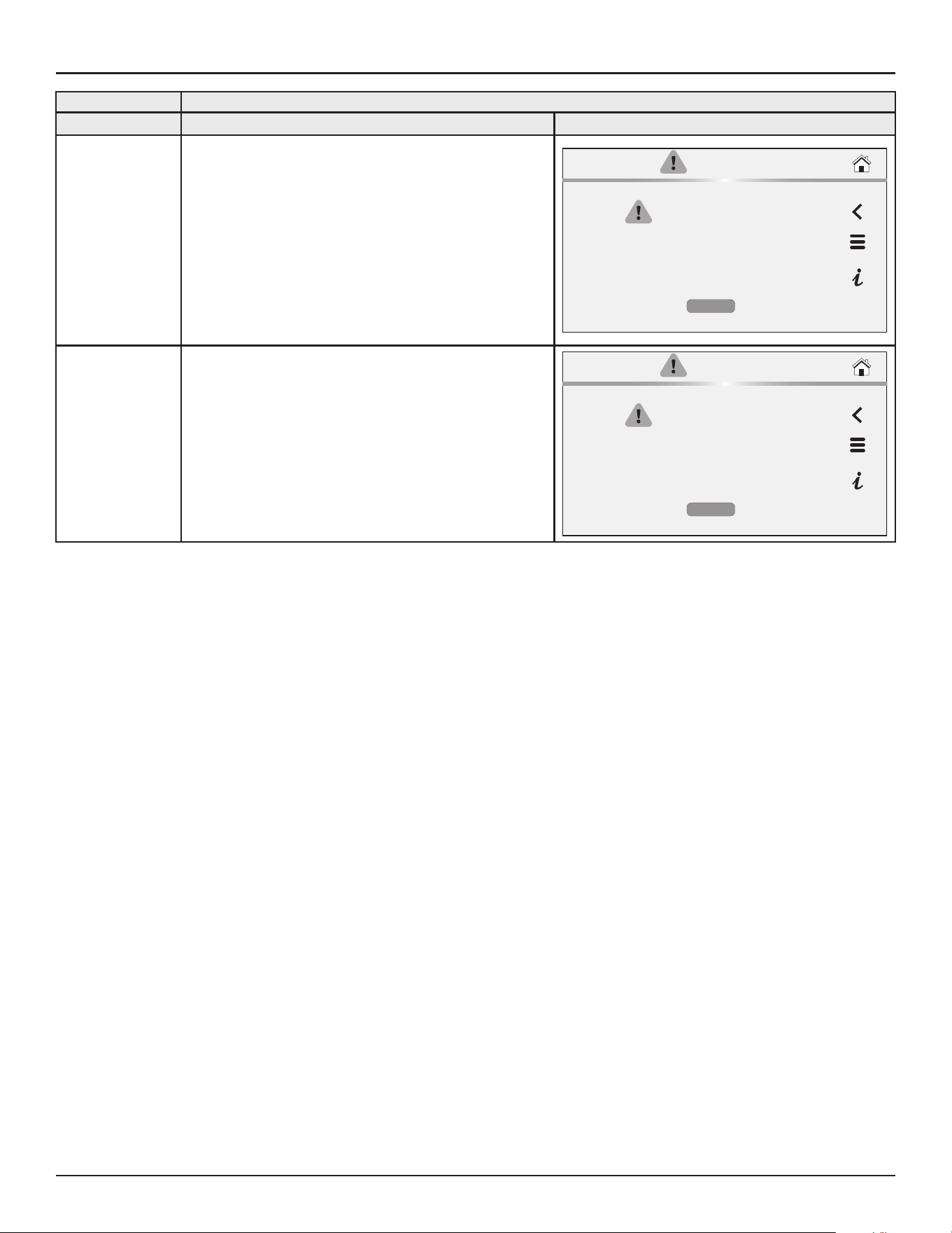
76 • Residential Gas Water Heaters
Troubleshooting
Fault and Alert Messages
FAULT CODE Possible Causes - Check/Repair
Displayed Fault/Alert Message
227
(227, 4001)
FMM Incompatible
The control system has detected that the Software Version on
the Flex Memory Module (FMM) is outdated.
The control system has detected that the Software Version on
the Flex Memory Module (FMM) is outdated
1. Typically caused by replacing control system components with
an older revision software
2. Contact technical support for further instructions
CURRENT FAULT
FMM Incompatible
Occurred:
04/28/2025 12:34 AM
The control system has detected that the
Software Version on the Flex Memory
Module (FMM) is outdated.
MORE
228
(228, 2015)
User Setpoints Error Detected
Data corruption of user adjustable setpoints led to factory reset
of default values.
Toggle the Enable/Disable switch to Diable, wait 30 seconds
and toggle back to Enable to clear fault and readjust setpoints.
CURRENT FAULT
User Setpoints Error Detected
Occurred:
04/28/2025 12:34 AM
Data corruption of user adjustable setpoints
led to factory reset of default values.
MORE
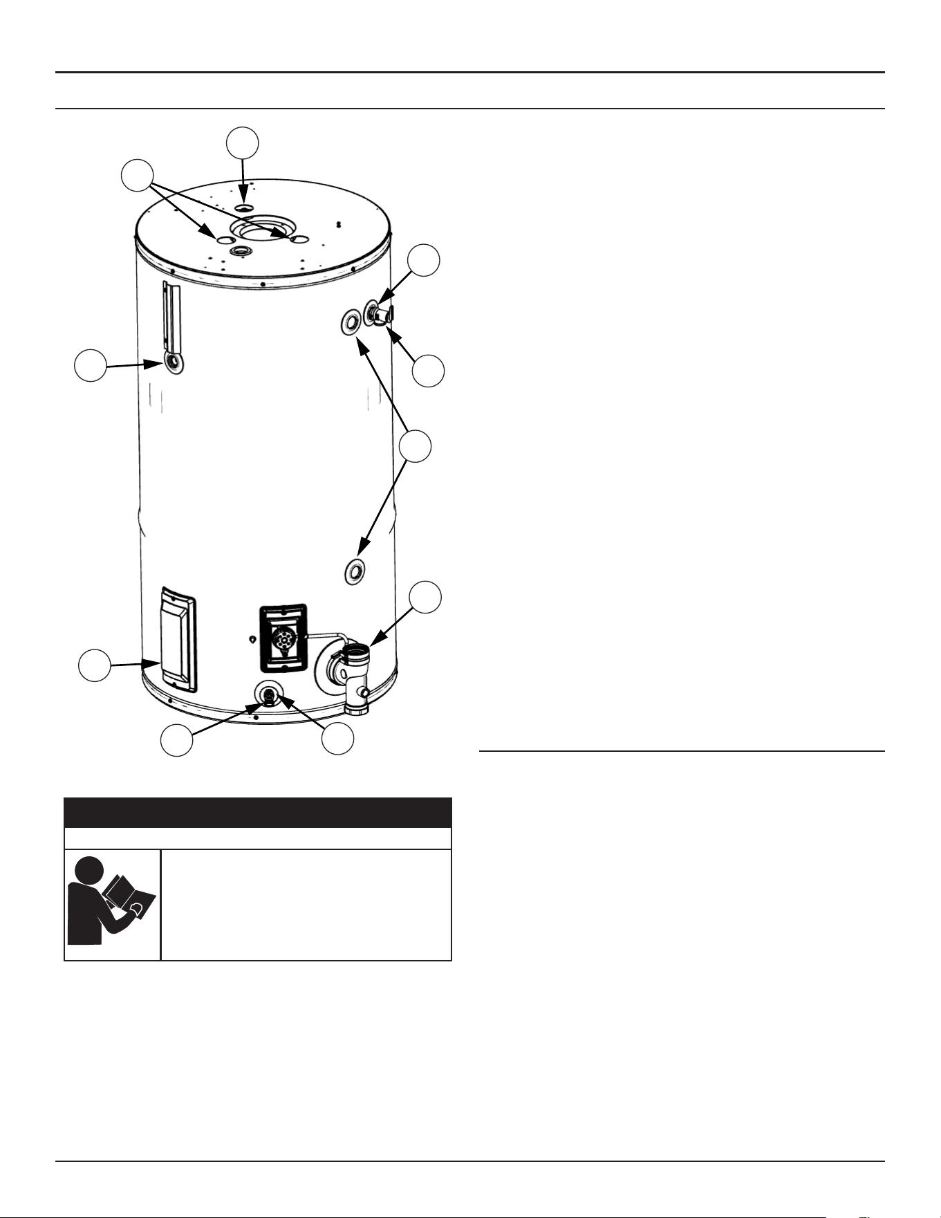
Troubleshooting
Residential Gas Water Heaters • 77
CHECKING FOR LEAKS
A
B
C
D
G
J
F
E
H
K
Figure 43. Leakage Checkpoints
Failure to follow these instrucons and safety
messages could result in death or serious injury.
Read and understand this instrucon manual and the
safety messages herein before installing, operang or
servicing this water heater.
This manual must remain with the water heater.
⚠
WARNING
Safety Hazard
Never use this water heater unless it is completely filled with water. To
prevent damage to the tank, the tank must be filled with water. Water must
flow from the hot water faucet before turning “ON” gas to the water heater.
A. *Condensation may be seen on pipes in humid weather or pipe
connections may be leaking.
B. *The anode rod fitting may be leaking.
C. Small amounts of water from temperature-pressure relief valve may be
due to thermal expansion or high water pressure in your area.
D. *The temperature-pressure relief valve may be leaking at the tank
fitting.
E. Water from a drain valve may be due to the valve being slightly opened.
F. *The drain valve may be leaking at the tank fitting.
G. Leakage from recirculation plug or pipe connection.
H. Leakage from the plug under the clean-out cover.
I. Leakage from the temperature probe connection (Not shown in figure).
J. Condensate from the exhaust connection.
K. *The temperature probe fitting may be leaking.
Leakage from other water heaters, water lines, or ground seepage should
also be checked.
* To check where threaded portion enters tank, insert cotton swab between
jacket opening and fitting. If cotton is wet, follow “Draining” instructions
in the “Periodic Maintenance” section and then remove fitting. Put pipe
dope or thread-sealer tape on the threads and replace. Then follow “Filling
the Water Heater” instructions in the “Installing the New Water Heater”
section.
WATER LEAK DETECTION
The water heaters covered by this manual have a water leak detection
feature that senses the buildup of water in vicinity of the appliance, setting
off an alarm to alert the end user. Please see the installation instructions
in included kit.
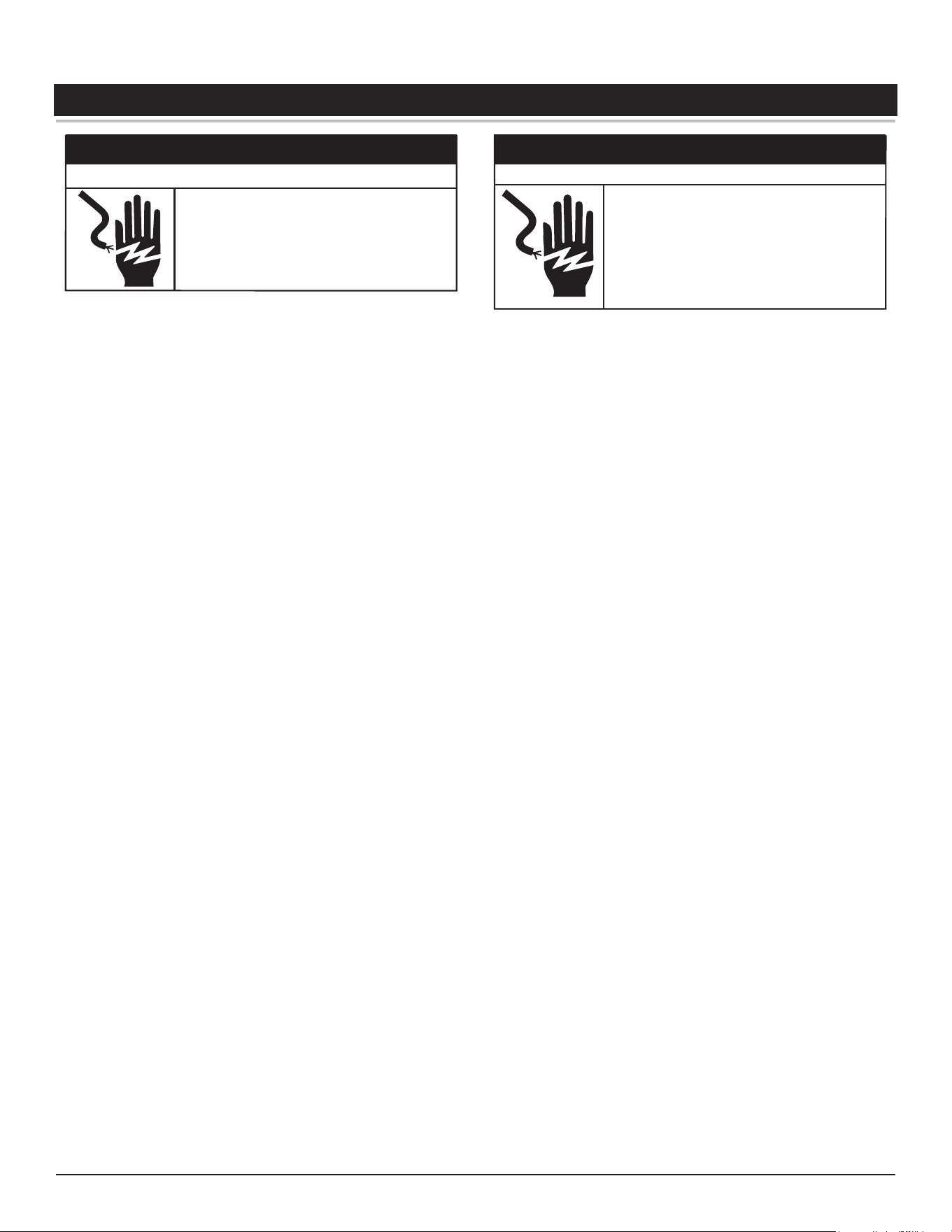
78 • Residential Gas Water Heaters
DIAGRAMS
⚠
CAUTION
Electrical Shock Hazard
Wiring errors can cause improper and danger-
ous operation, resulting in property damage,
injury or death.
• Label all wires prior to disconnection when
servicing controls.
• Verify proper operation after servicing.
•
Disconnect from electrical supply before servicing
unit. Replace all doors and panels before operating
heater.
• If any of the original wires supplied with the
appliance must be replaced, they must be replaced
with appliance wire material with minimum
temperature rating of 221°F (105°C) and a minimum
size of No. 18 AWG.
⚠
WARNING
Electrical Shock Hazard
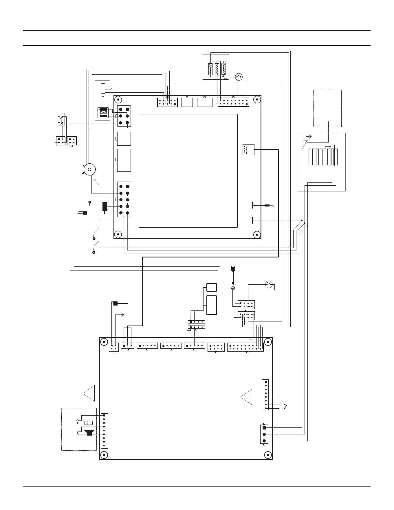
Diagrams
Residential Gas Water Heaters • 79
WIRING DIAGRAM
1 2
3
4
76
5
8 9 10
1
2 3
4
109
65
11
12 13 14
123
45
6
123
67
8
45
9
10
87
15 16
X5
X7
X1
X3
X10
FF2
FF1
Blower Power
Hall Sensor
PWM
GND
24Vdc
L1
N
PE/GND
Gas Valves
Motor Driven
N
L1
Connected to
heater jacket
PE/GND
NTC1
NTC2
Main Temperature Probe
Flame Sensor Rod
Spark XFMR
NTC3
Connected to
tank
1(L1)
2(N)
3(PE)
1
23
4
10
6 5
11121314
8
7
1516
J6
9
18 17
123
4
6 5
8
7
J8
1
23
45
1
23
45
1
23
4 15
23
J2
J3
J9
J4
98761
J5
J10
Enable/Disable Switch
(LDM)
Display 2.0
FMM
Key
Field Wiring
L1 PE/GNDN
+5V
D+
D-
DGND
+5V
D+
D-
DGND
+5V
D+
D-
DGND
D+
D-
DGND
Outlet Air
Inlet Air
Spark Rod
Connected to
tank PE/GND
Pressure SW
Pressure SW
TEMPERATURE
REGULATION CONTROL
(TRC)
COMBUSTION & SAFETY
CONTROL
(CSC)
NO FACTORY
CONNECTIONS
NO FACTORY
CONNECTIONS
AC Power
120 Vac/60Hz
Junction Box
PE/GND
P1
P2
P3
P4
P5
P6
P7
P8
OPEN
OPEN
OPEN
OPEN
CPAM N
CPAM L1
L1
N
L1
N
PE/GND
(OAPS)
(IAPS)
PE/GND
PE/GND
L1
N
Leak Detection Module
Throttle (MDT)
Blower Command
NO FACTORY
CONNECTIONS
123456
NO FACTORY
CONNECTIONS
NO FACTORY
CONNECTIONS
123
S4962VX1018
Field Wiring
WHITE
BLACK
GREEN
GREEN
BLACK
WHITE
WHITE
WHITE
GREEN
GREEN
GREEN
BLACK
BLACK
BLACK
BLACK
BLACK
BLACK
GREEN
WHITE
GREEN
GREEN
WHITE
GREEN
BLUEBLUE
ORANGE
ORANGE
BROWN
BROWN
BLUE
BLUE
WHITE
WHITE
BLACK
BLACK
GREY
GREY
VIOLET
VIOLET
BLACK
YELLOW
123
4
6 5
8
7
123
4
6 5
8
7
ORANGE
ORANGE
INNER EXT
BLACK
WHITE
GREEN
RED
BLUE
YELLOW
GREEN
RED
YELLOW
BLUE
BLACK
GREY
VIOLET
RED
YELLOW
GREEN
RED
BLACK
BLUE
WHITE
12
4 3
12
4 3
2A
2
1A
1
WHITE
BLACK
GREEN
RED
1234
1234
RED
YELLOW
BLUE
BLACK
NO FACTORY
CONNECTIONS
P1, P2, P3, P4, P5, and P6 ARE NOT USED
Powered Anode
Connected to tank
PE/GND
GREEN
BLUE
5
4
3
2
EXTERNAL ENABLE
DISABLE SWITCH
J7
8765
J13
12
43
D
D
GREEN
2
1
3
4
Louvre
Alarm
Figure 44. Wiring Diagram

Copyright © 2025. All rights reserved.