-
1
-
E2227
Rev B 06/01/25
INSTALLATION & OPERATIONS INSTRUCTIONS
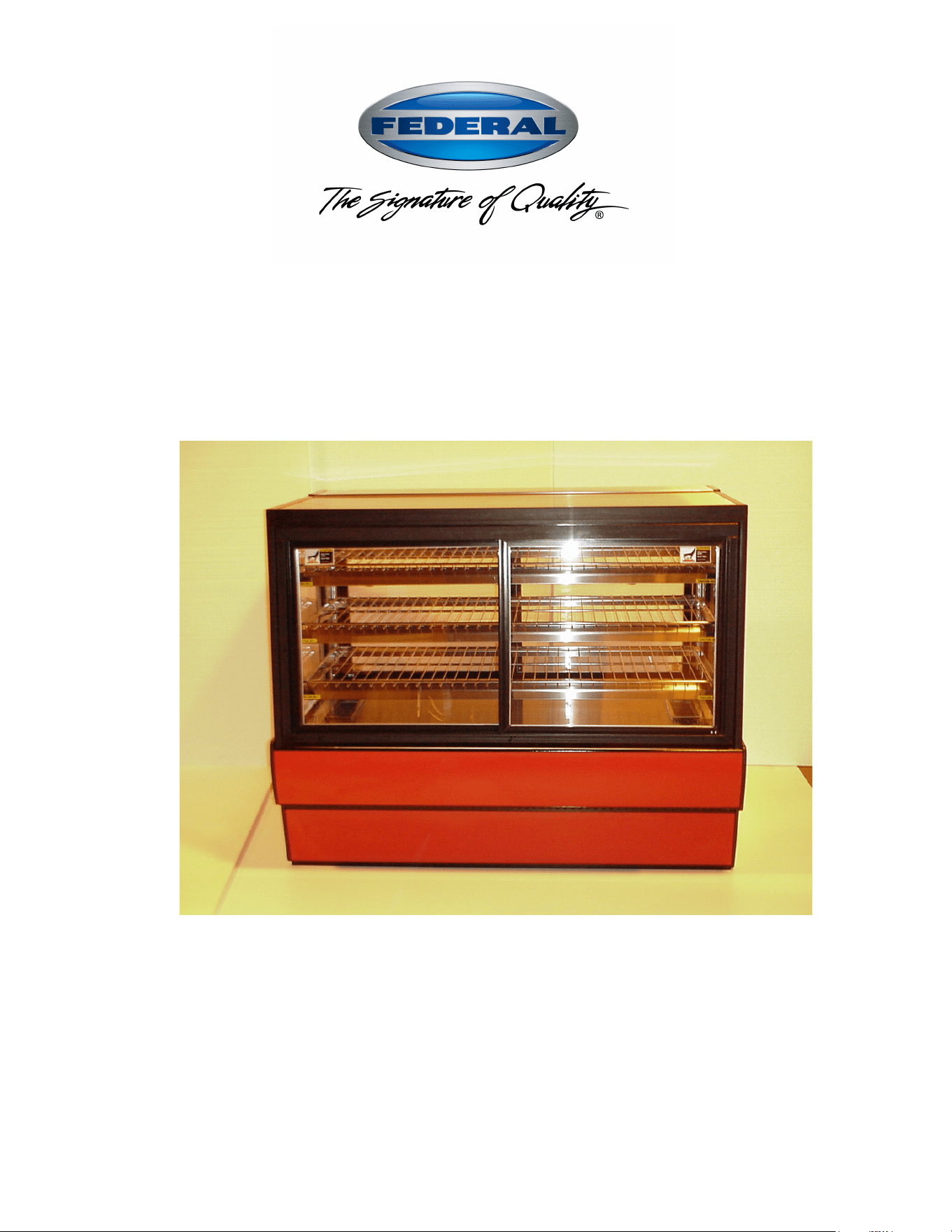
HDP HOT DISPLAY PACKAGE
KEEP THIS MANUAL FOR FUTURE REFERENCE
Engineering and technical data are subject to change without notice.
FEDERAL INDUSTRIES 215 Federal Avenue Belleville, WI 53508
Toll Free 1(800) 356-4206 WI Phone (608) 424-3331 Fax: (608) 424-3234

-
2
-
CONTENTS
INTRODUCTION ....................................................................................................................................... 3
WARNING LABELS & SAFETY INSTRUCTIONS ............................................................................. 4
PRE-INSTALLATION PROCEDURES .................................................................................................. 5
Inspection For Shipping Damage ................................................................................................ 5
INSTALLATION INSTRUCTIONS......................................................................................................... 5
Locating The Display Case ......................................................................................................... 5
Removing Case From Shipping Skid ....................................................................................... 5-6
Grill Removal .............................................................................................................................. 6
Cleaning ...................................................................................................................................... 6
Trim Kits Installation ....................................................................................................................... 7
Exterior Trim .............................................................................................................................. 7
Interior Trim ................................................................................................................................ 8
ELECTRICAL INFORMATION & GROUNDING ............................................................................... 9
OPERATING INSTRUCTIONS ............................................................................................................. 10
Controls ................................................................................................................................ 10-11
Initial Start-Up .......................................................................................................................... 11
Placing Product into Case ......................................................................................................... 12
Unit Shut Down ........................................................................................................................ 12
Shelves ...................................................................................................................................... 12
Rear Package Shelf ................................................................................................................... 13
Sliding Doors ............................................................................................................................ 13
Swing Doors .............................................................................................................................. 13
SHELVING INSTALLATION & REMOVAL ...................................................................................... 14
Shelving ............................................................................................................................... 14-15
Wire Shelves ............................................................................................................................. 16
MAINTENANCE ...................................................................................................................................... 17
Water Pan Refilling .............................................................................................................. 17-18
Light Replacement .................................................................................................................... 18
CLEANING INSTRUCTIONS ................................................................................................................ 19
Daily Cleaning .......................................................................................................................... 19
Weekly Cleaning ....................................................................................................................... 20
Interior Cleaning ....................................................................................................................... 20
Exterior Cleaning ................................................................................................................. 21-22
SERVICE INFORMATION .................................................................................................................... 23
Pre-Service Checklist ........................................................................................................... 23-24
Special Service Situations ......................................................................................................... 25
SALE & DISPOSAL ................................................................................................................................. 25
Owner Responsibility ................................................................................................................ 25
ELECTRICAL DATA .............................................................................................................................. 26
WIRING DIAGRAMS ........................................................................................................................ 27-28
REPLACEMENT PARTS .................................................................................................................. 29-30
-
3
-
INTRODUCTION
Thank you for purchasing a Federal Industries display case. This manual contains important instructions
for installing and servicing the Curved Glass and Hi-Volume Hot Display Package Units. A repair parts
list and wiring diagram are also included in the manual. Read all of these documents carefully before
installing or servicing your case.
NOTICE
Read this manual before installing your case. Keep this manual and refer to it before doing any
service on the equipment. Failure to do so could result in personal injury or damage to the case.
NOTICE
Installation and service of the electrical components in the case must be performed by a
licensed electrician.
The portions of this manual covering components contain technical instructions intended only for
persons qualified to perform electrical work.
DANGER
Improper or faulty hookup of electrical components in the case can result in severe injury or
death.
All electrical wiring hookups must be done in accordance with all applicable local, regional, or
national standards.
SERIAL NUMBER
Record the model and serial numbers of the case for easy reference. Always refer to both model and
serial numbers in your correspondence regarding the case.
Case Model__________________________ Serial Number______________________
This manual cannot cover every installation, use, or service situation. If you need additional information,
call or write us:
CUSTOMER SERVICE DEPARTMENT
Federal Industries
215 Federal Avenue
Belleville, WI 53508
Toll Free (800) 356-4206 / WI Phone (608) 424-3331
-
4
-
WARNING LABELS & SAFETY
INSTRUCTIONS
This is the safety-alert symbol. When you see this symbol on your case or in the
manual, be alert to the potential for personal injury or damage to your equipment.
Be sure you understand all safety messages and always follow recommended precautions and safe
operating procedures.
NOTICE TO EMPLOYERS
You must make sure that everyone who installs, uses, or services your case is
thoroughly familiar with all safety information and procedures.
Important safety information is presented in this section and throughout the manual. The
Following signal words are used in the warning and safety messages:
DANGER: Severe injury or death will occur if you ignore the message.
WARNING: Severe injury or death can occur if you ignore the message.
CAUTION: Minor injury or damage to your case can occur if you ignore the message.
NOTICE: This is important installation, operation, or service information. If you ignore the
message, you may damage your case.
The warning and safety labels shown throughout this manual are placed on your Federal
Industries case at the factory. Follow all warning label instructions. If any warning or safety
labels become lost or damaged, call our customer service department at 1(800) 356-4206 for
replacements.
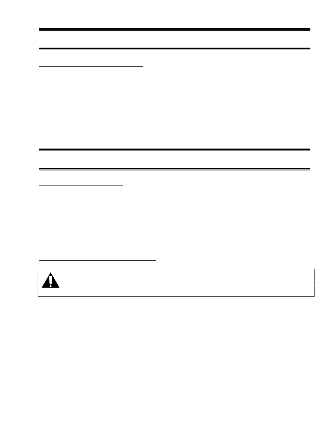
CAUTION
POWER BEFORE
RISK OF ELECTRIC
SHOCK DISCONNECT
91-12340
SERVICING UNIT.
CAUTION
HAZARDOUS MOVING PARTS
DO NOT OPERATE UNIT WITH
DISPLAY PANS REMOVED.
Hot surface can
cause severe burns
Do not touch
CAUTION
91-10936
-
5
-
PRE-INSTALLATION PROCEDURES
Inspection for Shipping Damage
You are responsible for filing all freight claims with the delivering truck line. Inspect all cartons
and crates for damage as soon as they arrive. If damage is noted to shipping crates, cartons, or if
a shortage is found, note this on the bill of lading (all copies) prior to signing.
If damage is discovered when the case is uncrated, immediately call the delivering truck line and
follow up the call with a written report indicating concealed damage to your shipment. Ask for an
immediate inspection of your concealed damage item. Crating material must be retained to show
the inspector from the truck line.
INSTALLATION INSTRUCTIONS
Locating the Display Case
The case should be located where it is not subjected to the direct rays of the sun, heating ducts,
grills, radiator, or ceiling fans, nor should it be located near open doors or main door entrances.
Also, avoid locations where there are excessive air movement or air disturbances.
Countertop and floor mounted units must be sealed to the floor or counter using a NSF listed
sealant. This is to prevent liquid spillage on the adjacent surfaces of the floor or counter top from
passing under inaccessible portions of the equipment and allow for proper sanitary operation. The
sealed surfaces should be cleaned of any dirt, debris or oil and allowed to dry before sealant
application.
Removing Case From Shipping Skid
CAUTION: Do not push against the top glass, front glass, end glass, doors or
door frames when removing the case from the skid or moving the case. Case
damage or glass breakage could result.
1. Remove crate top and sides and note missing or damaged items as explained in the pre-installation
procedures outlined above.
2. Move the case as near as possible to the final location and before removing it from the shipping skid.
3. If your case is supplied with plastic end panels, remove them by lifting them in an upward direction.
Set these end panels aside to be reinstalled after case is placed in proper position.
4. Remove the (4) brackets that secure the case to the shipping skid.
-
6
-
5. Use the lifting handles located in each end of the case and lift case off of skid and into required
position.
6. Level and square the case as needed by placing shims under each corner of base.
7. The leveled case must be sealed to the floor using a NSF Listed Sealant.
8. If plastic end panels are required, reinstall them on to case. Hook the key slot located on the inside of
the end panel down over screws located on each end of case.
Grill Removal
DANGER: Electric shock hazard. Do not operate unit with panels removed.
There is a removable panel at the rear of the case. The panel allows access to the control panel
enclosure, water pan, and the field wiring connection box. Remove this panel to make field
wiring connections. See electrical information and grounding section of this manual before
wiring case.
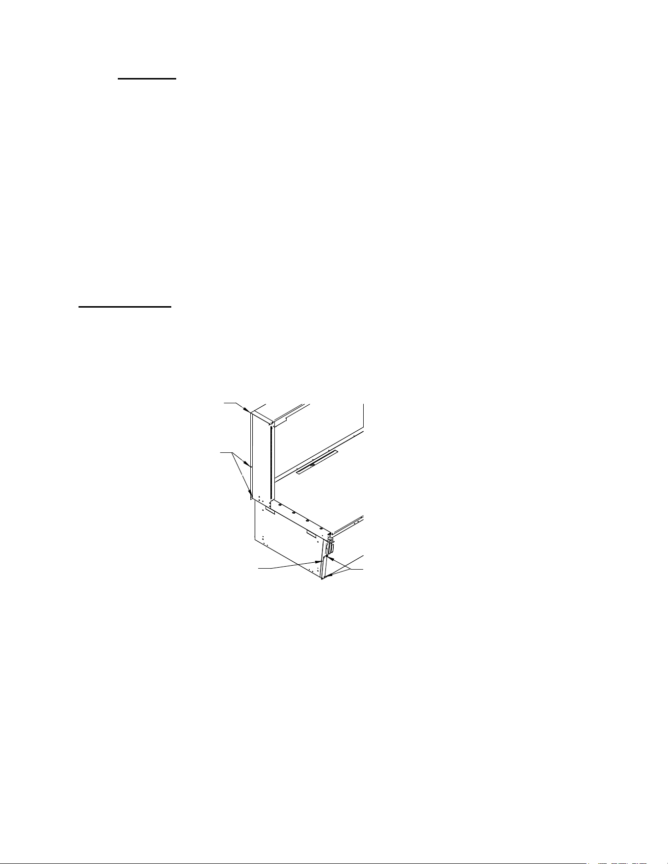
1. Remove the rear grill panel thumb screws from top of rear grill.
2. Tilt the top of rear grill panel outward as shown in illustration on the right.
3. Pull rear grill panel tabs up and out of slots in base of case.
3. REAR GRILL
PANEL TABS
1. REAR GRILL
PANEL SCREWS
2.
E2227-1
-
7
-
Cleaning
For initial setup, clean the case as outlined in the weekly cleaning section of this manual.
Trim Kits Installation
Follow the “Case Installation” procedures in this manual for each display case that is going to be
adjoined in a lined up. Additional cases must be place directly next to the adjoining end of the first case.
Push cases together as close as possible keeping the front of the cases in alignment. Once adjoining case
is in proper position complete all of the procedures outlined in the “Case Installation” section in this
manual before installing the trim kit as outlined below.
Note: The Laminated plastic end panels and end panel screws are not used on the adjoining ends of the
cases that are to be butted together.
Exterior Trim
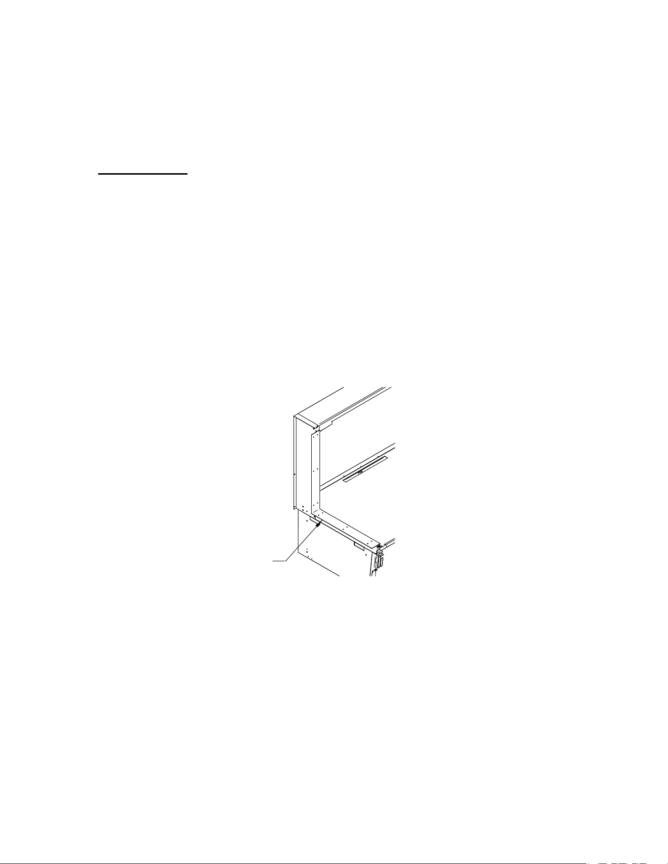
1. Remove the (3) 8-32 screws located on rear corner of each case and set aside (If preinstalled). These
screws will be used to attach rear exterior trim strip to case. Note: For units with rear packing shelf ,
These screws hold the package shelf standard to the case. The packing shelf and packing shelf
standard must be temporarily removed for installation of rear exterior trim.
2. Remove the adhesive liner from the inside of the rear exterior trim strip and firmly place it over the
top and down the back of case. Be sure to center rear exterior trim strip over seem between cases and
to align slots with holes in case rear (If holes are provided).
3. Fasten rear exterior trim strip to each case with the (3) 8-32 screws previously removed. If no holes
are provided to fasten trim strip, use the (3) #8 self-drilling screws provided.
Note: For units with rear packing shelf, Reattach rear packing shelf standard over the top of rear
exterior trim strip using the existing holes in case. Place packing shelf back on to case in desired
standard slot.
4. Use a NSF approved silicone to seal rear exterior trim strip along the top surface of case.
5. Remove the (2) screw located on the front corner of each case and set aside. These screws will be
used to attach front exterior trim strip to case. Note: For units with front package shelf, these screws
EXTERIOR REAR
TRIM STRIP
EXTERIOR FRONT
TRIM STRIP
REAR SCREW
E1954-11
FRONT SCREW
-
8
-
hold the package shelf to the case. The package shelf must be temporarily removed for installation of
front exterior trim.
6. Fasten front exterior trim strip to each case with the (2) 8-32 screws previously removed.
Note: For units with front package shelf, Reattach front package shelf over the top of front exterior
trim strip case with the (2) 8-32 screws previously removed.
Interior Trim
The interior trim kit is used when adjoining cases have one glass panel or no glass panel between
them.
1. On units with sliding rear doors, remove both rear doors from track by lifting doors upward until the
bottom edge of door clears the lower track. Swing the bottom of door outward and down out of top
track.
On units with rear swing doors completely open doors to allow access to interior of case.
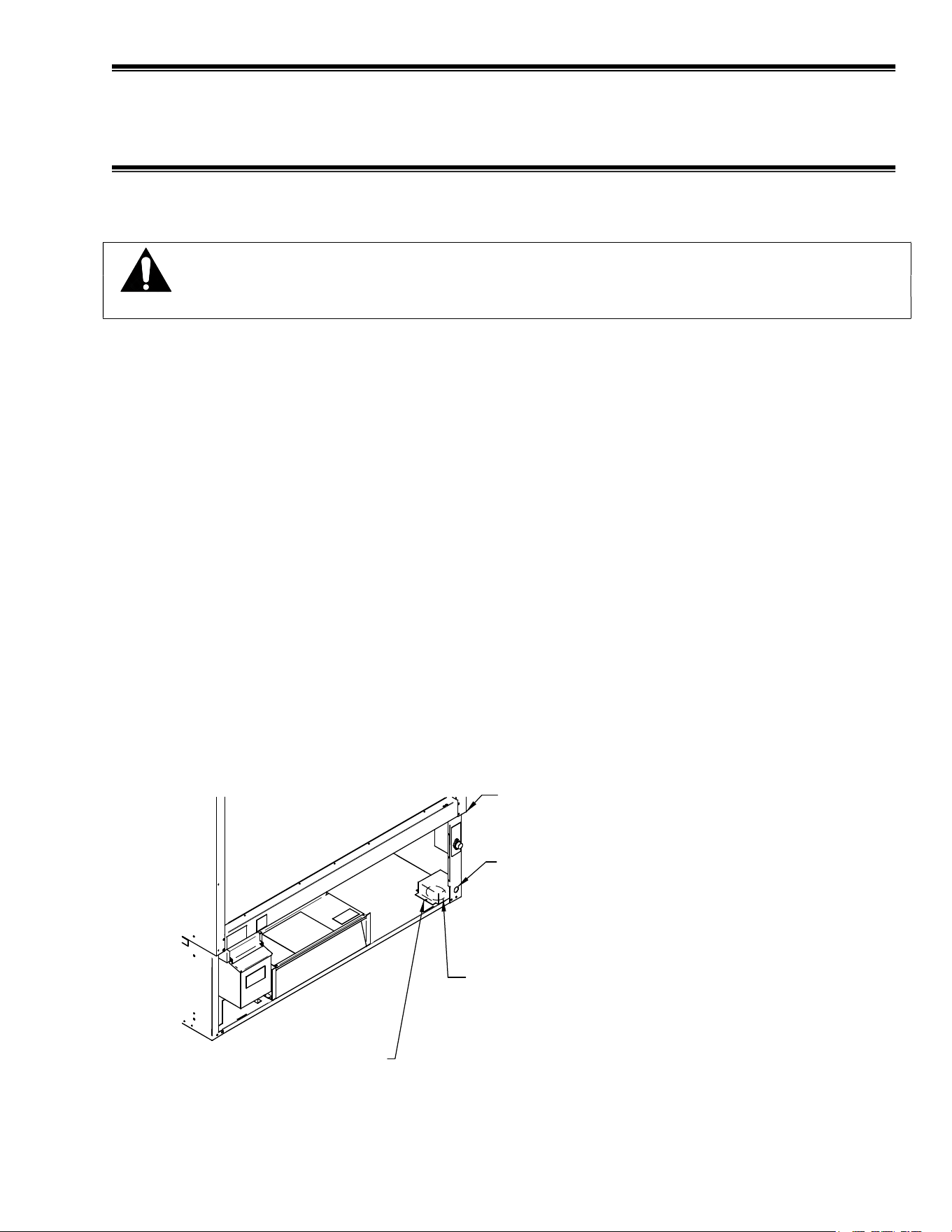
2. Cases with no glass panels: Remove the adhesive liner from the inside of the interior trim strip and
firmly place it over the center gap between the case interiors.
Cases with one glass panel: The interior glass trim is placed in the adjoining case that does not have
an end glass panel. Remove the adhesive liner from the inside of the interior trim strip and firmly
place it against the glass trim of adjoining case with the end glass panel.
3. Fasten interior glass trim with the stainless steel self drilling screws supplied with interior trim kit
INTERIOR TRIM STRIP
E1954-12
-
9
-
ELECTRICAL INFORMATION &
GROUNDING
This Case Must Be Grounded
DANGER: Improper or faulty hookup of electrical components in the
display case can result in severe injury or death.
Only a licensed electrician must perform all case electrical connections.
All electrical wiring hookups must be done in accordance with all applicable local, regional, or national
electrical standards.
A separate circuit for each display case is recommended to prevent other appliances on the same circuit
from overloading the circuit and causing malfunction.
The electrical service must be grounded upon installation.
This unit is designed for permanent connection to a power source. See the electrical data plate located at
the rear of the case for proper circuit size and wire ampacity.
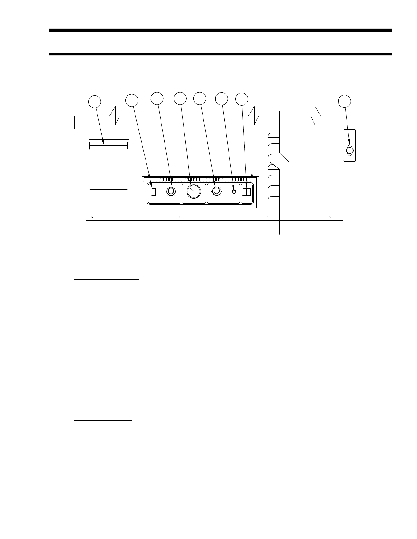
The electrical connection box is accessible from the rear of the case. Remove rear grill from back of case
(See “Grill Removal” in the installation section of this manual). See diagram below for location of the
field wiring connection box.
BACK OF CASE
OVERHANGS BASE 1"
7/8" DIA ELECTRICAL ENTRANCE
ON REAR OF CASE.
1" FROM SIDE OF BASE,
1-3/4" FROM FLOOR.
2-3/4" DIA ELECTRICAL ENTRANCE
ON REAR OF CASE.
2-3/4" FROM SIDE OF BASE,
2-1/8 FROM REAR OF BASE.
FIELD CONNECTION
COVER.
E2227-2
-
10
-
OPERATING INSTRUCTIONS
A. Heat Switch On/Off
This switch controls all heating and humidity functions of unit. This switch is on when the red
portion of switch is exposed.
B. Heat Temperature Control
This control regulates the air temperature of the case. Turn counter-clockwise to operate case at
lowest temperature setting of approximately 100
o
F, turn clockwise to operate case at highest
temperature setting of approximately 180
o
F. When proper temperature is reached, air heaters shut
off, but the blower and humidity will remain running. When temperature drops below specified
setting, the air heater turns back on.
C. Temperature Indicator
The temperature indicator measures air temperature of air returning to heating duct. It does not
actually measure case interior or food temperature.
D. Humidity Control
This control regulates humidity level in the case. Turn counter-clockwise to operate water heater
at highest temperature to provide the highest humidity level. Turn clockwise to operate water
heater at lowest temperature to provide minimal or no humidity level.
HEAT
LO
TEMPERATURE
HI
HUMIDITY
HI
OFF
LO
LOW WATER
LIGHTS
B
A
C D
E
F
G
H
-
11
-
E. Low Water Light
This light turns on when humidity water level is low. When this light is lit, the humidity system
shuts off until additional water is added to water pan. Air heat function remains active during low
water situations.
F. Light Switches
These switches control lights on the interior of the case. The switches are on when the red side of
switch is exposed. The lights operate independently from the air heat control. The lights provide
additional interior heat, and should be used whenever the heater system is being used.
G. Water Pan
The water pan holds water to be used for humidifying case air.
H. Fuse
The fuse is in line with all electrical components except the air heater. The fuse must always be
replaced with the same type of fuse supplied from factory (SC-15 Amp Time Delay).
Initial Start-Up
After unit has been located, sealed to floor, and properly wired, you are now ready to begin using your
heated display case to serve your customers.
1. Clean case thoroughly before proceeding. (See: Weekly Cleaning Instruction Section for proper
procedure.)
2. Fill water pan with fresh, clean water. Using deionized water will minimize scale build-up on
water heater components. The low water light will shut off. (See: General Maintenance Section-
Water Pan Filling for proper filling process.)
3. Turn on heat switch.
4. Turn heat temperature control clockwise to fifth mark.
5. Turn humidity control counter-clockwise to fifth mark.
6. Turn on light switches to illuminate interior of case.
7. Allow two (2) hours for case to reach proper temperature and stabilize.
8. Adjust heat temperature control until temperature indicator reaches desired temperature.
CAUTION: Temperatures of many types of food must not drop below set levels. Check
local codes to determine minimum food temperature requirements in your
area.
9. Adjust humidity control to reach desired humidity level.
-
12
-
Placing Product into Case
1. Once temperature and humidity levels have stabilized to desired conditions, place preheated,
packaged product into case. Allow enough spacing around product to allow proper circulation of
heated air throughout the case.
WARNING: Interior surfaces are hot. DO NOT TOUCH.
NOTICE: Packaged product containers must be able to withstand temperatures
up to 200
o
F.
NOTICE: This case is designed to display preheated, precooked packaged food
products and is not intended to be used to bring refrigerated or frozen
food to serving temperature. Food products being placed in case must
be preheated to safe serving temperature. Check local code
requirements in your area.
2. Adjust temperature during peak serving periods to maintain proper product temperature.
3. Refill water pan with fresh clean water daily or whenever the low water light turns on.
Note: Using deionized water will minimize scale build-up on water heater components.
Unit Shutdown
1. Remove all product from the case.
WARNING: Interior surfaces of case are hot. DO NOT TOUCH.
2. Turn interior lights off by placing both light switches to the off position.
3. Turn heat control to low position. Allow blower to run for 5 minutes to allow heater to cool
down. (Mark dial location so temperature can be reset upon start-up.)
4. Turn heat switch off by placing heat switch to off position.
Shelves
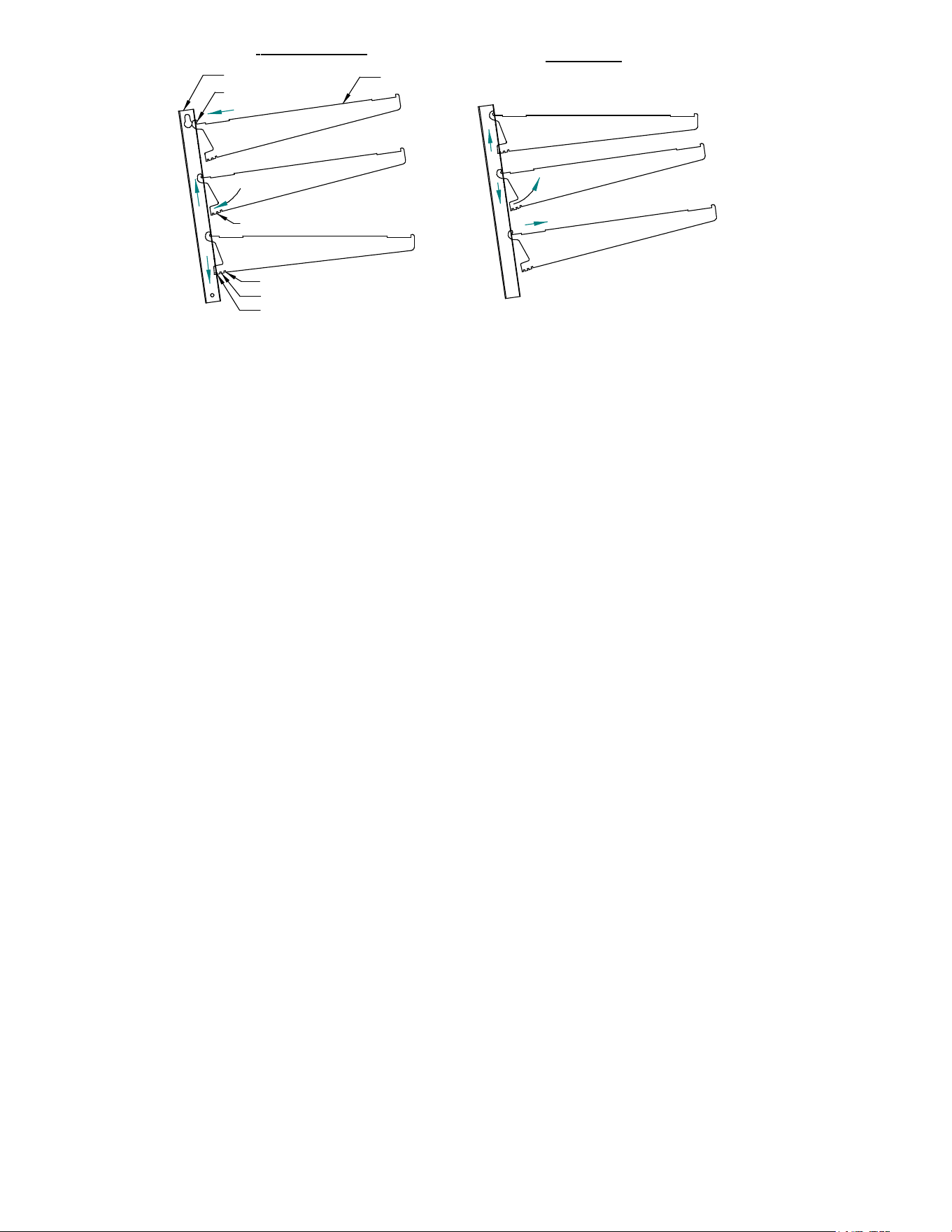
Each display is furnished with shelves that are adjustable up and down and can be tilted in three
angular positions. See “Shelving Installation & Removal” section of this manual for proper
installation, adjustment and removal of shelving.

-
13
-
Rear Package Shelf (optional)
The rear package shelf is removable and adjustable up and down. It can be removed or adjusted
by lifting rear package shelf up and out until the bracket is disengaged from shelf standard. It can
then be moved to desired height location and reattached.
Sliding Rear Doors
The doors can be easily removed by lifting doors upward until the bottom edge of door clears the
lower track. Swing the bottom of door outward and down out of top track.
Clean the door track frequently for easy door operation. A Very light film of lubricant, such as
PAM, will help the doors slide easily.
-
14
-
SHELVING INSTALLATION & REMOVAL
Shelving
1. Turn the light switches to the off position.
2. On units with sliding rear doors, remove both rear doors from track by lifting doors upward until the
bottom edge of door clears the lower track. Swing the bottom of door outward and down out of top
track. On units with rear swing doors, completely open doors to allow access to interior of case.
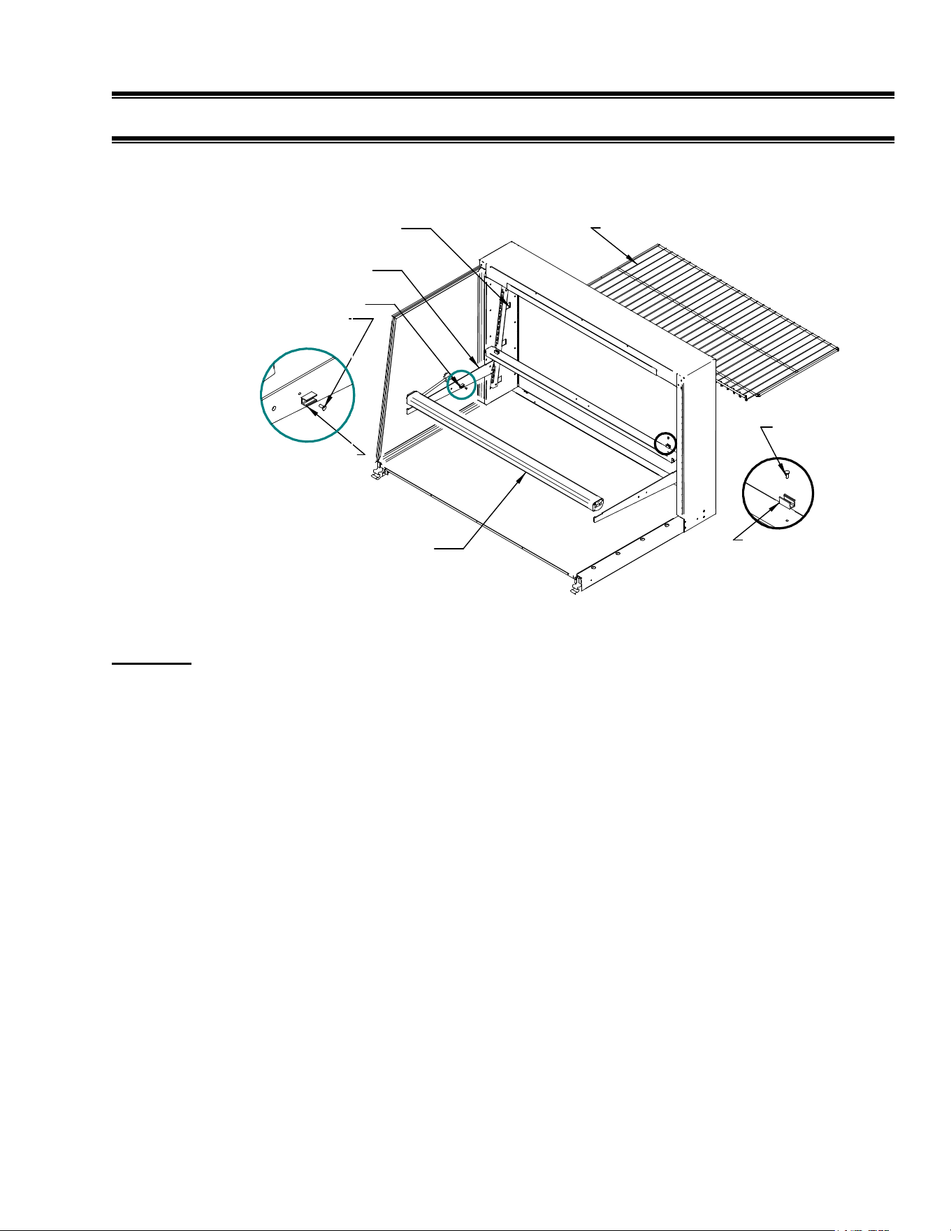
3. Insert a shelf bracket in the desired shelf standard slot on one side of case. Follow the instruction in
the illustration below. Place an additional shelf bracket in the same shelf standard slot on the
opposite end of case. Repeat for additional shelf tiers. For first time installation it may be necessary
to attach the clear plastic clips to only the shelf brackets located on the side of the shelf light cord.
Use the 6-32 x ¼ flat head screws supplied with unit to attach clear plastic clips to the 1/8 hole on the
inside of the shelf brackets. This step may have already been performed at the factory for you.
NOTE: Do not allow shelf bracket to hit side glass
SHELF LIGHT
SHELF BRACKET
CLEAR PLASTIC CLIP
CLEAR PLASTIC CLIP
WIRE SHELF
FEMALE SHELF
LIGHT SOCKET
6-32 X 1/4 FLAT
HEAD SCREW
6-32 X 1/4 FLAT
HEAD SCREW
CLEAR PLASTIC CLIP
E2227-4
B
DETAIL B
A
DETAIL A
-
15
-
4. Hang one end of shelf light housing on the front notch of a shelf bracket and then the other end of
shelf light housing on the notch of the shelf bracket on the opposite end. Repeat for each additional
shelf tiers. NOTE: On models without shelf lights, use a shelf support instead of a shelf light
housing.
5. Push shelf light cords into clear plastic clip located on inside of shelf brackets.
6. Remove the cap from the appropriate female light sockets. If socket is not being used for a shelf light,
the cap must be plugged into socket for entire light system to operate. NOTE: Grip each side of cap
firmly. Wiggle and pull cap straight out of socket. Do not roll cap during removal.
7. Plug in each shelf light by aligning the male pins on the appropriate shelf light cord plugs with the
female light sockets and push together. NOTE: Do not roll plug during insertion.
8. Hang one end of the shelf support on to the rear notch of one shelf bracket and then on the rear notch
of the shelf bracket on the opposite side. Repeat for additional shelf tiers.
9. Place supplied shelving onto shelf supports as outlined in the appropriate “Shelf Installation” section
of this manual.
10. On units with sliding rear doors, re-install both rear doors by lifting top of door into top track and
swinging bottom of door onto bottom track. Install door labeled “inner door” first on inner track and
door labeled “outer door” second on outer track.
11. Place supplied shelving onto shelf supports as outlined in the appropriate “shelf Installation” section
of this manual.
12. On units with sliding rear doors, re-install both rear doors by lifting top of door into top track and
swinging bottom of door onto bottom track. Install door labeled “inner door” first on inner track and
door labeled “outer door” second on outer track.
0° NOTCH
6° NOTCH
12° NOTCH
4
E1954-3
1
2
3
4
INSTALLATION
REMOVAL
2
3
1
TOP HOOK
BOTTOM TAB
SHELF BRACKET
SHELF STANDARD
A.. Place shelf bracket top hook into desired shelf
standard slot.
B. Lift shelf bracket top hook to allow shelf bracket
bottom tab to clear shelf standard slot.
C. Swing shelf bracketbottom tab into shelf standard
slot.
D. Place the desired shelf bracket notch of 0, 6, or 12
degrees onto bottom of shelf standard slot.
A. Lift shelf bracket up to allow shelf bracket notch
to clear the bottom of shelf standard slot.
B. Swing shelf bracket bottom tab out of shelf
standard slot.
C. Drop shelf bracket down to allow shelf bracket top
hook to clear top of shelf standard slot.
D. remove shelf bracket top from shelf standard slot.

-
16
-
Wire Shelves
1. For first time installation, it may be necessary to attach the clear plastic clips to each end of the rear
shelf supports. Use the 6-32 x ¼ flat head screws supplied with unit to attach clear plastic clips to the
1/8 hole on each side of shelf support. This step may have already been performed at the factory for
you. Repeat for each rear shelf support tier. (See illustration E1594-2 Detail C) NOTE: On 73”
long shelf supports, attach (2) additional clear plastic clips into 1/8 hold near the center of rear shelf
supports.
2. With rear sliding doors removed or rear swing door open, place front of wire shelf onto front shelf
light. (On front shelf support for models without shelf lights)
3. Snap the rear of shelf into the clear plastic clips on rear shelf support.
4. Repeat 2 & 3 for each tier.
NOTE: Units with 73” rear shelf supports uses (2) wire shelves per tier. All other units use (1) wire
shelf per tier.
-
17
-
MAINTENANCE
CAUTION: Before any service work is performed on the case, make sure all power is
disconnected to the case.
NOTICE: Installation and service of the electrical components in the case must be performed by
a licensed electrician.
Service problems or request for repair parts from authorized service agencies, trained service personnel,
or owners should be referred to:
CUSTOMER SERVICE DEPARTMENT
Federal Industries
215 Federal Avenue
Belleville, WI 53508
Toll Free: (800) 356-4206 / WI Phone (608) 424-3331
Fax: (608) 424-3234
WATER PAN FILLING
Depending on the amount of usage your heated display case receives and the amount of humidity you
require will determine the frequency the water pan will need refilling.
The water pan requires refilling when the low water light located on the control panel illuminates. Water
can be added at any time that is convenient for the operator. Refilling at regular intervals and not
allowing the low water light to turn on will provide the most consistent humidity level in the case.
Note: When the low water light illuminates, the water heater shuts off and humidity will no longer be
generated in the case.
CAUTION: Water in water pan is extremely hot. Do not touch surface of pan face and
use caution when lifting water pan lid to avoid being burned from
escaping hot steam.
1. Find a clean container, preferably with a handle and a pouring spout. Note: An empty water pan will
hold approximately 3 ½ to 4 gallons of water.
2. Fill a container with clean fresh water. Note: Using deionized water will minimize scale build-up on
water heater components. If unit is running it is best to use warm or hot water to prevent cooling of
case temperature and allowing less time for water to reach proper temperature.
-
18
-
3. Lift lid of water pan and slowly pour water into pan. Fill pan to top but do not allow water to
overflow.
CAUTION: If any water is spilled during filling procedure wipe it up immediately to
prevent a slippery floor condition.
4. Close water pan lid and empty remaining water (if any) into sink or floor drain.
NOTICE: Water pan must be cleaned regularly to maintain proper performance and prevent
mechanical failures. (SEE CLEANING HEAT DUCT & WATER PAN)
LIGHT BULB REPLACEMENT
Light bulbs are removed by unscrewing counter clockwise. Install bulbs by screwing in
clockwise. Do not over tighten.
When replacing lights, use direct equivalent to the original bulbs. Bulbs must have protective
coating to prevent shattering if broken.
NOTICE: Lights in this case are an additional source of heat and allow unit to heat to its
maximum capacity. Replace burned out bulbs as soon as possible. Bulbs must have
protective coating to prevent shattering if broken.
-
19
-
CLEANING INSTRUCTIONS
Daily Cleaning
The case should be cleaned thoroughly, as described in the weekly cleaning section, before it is
used for the first time.
NOTICE: Avoid splashing or soaking any electrical components with water to
prevent electrical damage to the case.
NOTICE: Shut off lights and power switches and remove all product from case.
Allow sufficient time for the unit to reach room temperature before
proceeding with cleaning.
NOTICE: Remove all product from case before proceeding with cleaning
procedure.
Note: For major spills or foreign material buildup use complete weekly cleaning instructions.
1. Clean all foreign materials from the door opening.
2. Wipe complete interior of case using a damp cloth.
3. Tilt the front glass forward as described in the illustrations below. This will allow easier
access to clean interior front and side glass. The glass can then be cleaned with common
window cleaners.
STRAIGHT GLASS
E1954-10
PULL HANDLE
OPEN FRONT GLASS:
1. Stand in front of unit and grab the pull
handle with finger tips. It may be necessary
to push on front glass from inside of case.
2. Pull front glass outward until the glass
rests on front glass stops.
CLOSE FRONT GLASS:
1. Stand in front of unit and push on front
of front glass with both hands.
2. Firmly push front glass towards rear of unit
until front glass handle is against top glass
front.
-
20
-
4. The remaining exterior surface should be wiped down using any ammoniated cleaners or
soapy warm water.
Note: Detergents are not recommended and do not use abrasive cleaners or pads to prevent
scratching of surfaces.
Weekly Cleaning
This procedure is recommended on a weekly basis. It may need to be performed more often if
necessary to maintain a clean, sanitary case. The case should be cleaned to this procedure before
using the first time.
NOTICE: Avoid splashing or soaking any electrical components with water to
prevent electrical damage to the case.
NOTICE: Shut off light and power switches and remove all product from case. Allow
sufficient time for the unit to reach room temperature before proceeding
with cleaning.
Interior Cleaning
1. Remove all interior shelving as described in the shelving installation and removal section of this
manual.
2. Remove both shelf standards from interior of case. First remove thumbscrew at bottom of shelf
standard and then slide shelf standard up to allow top key slot to clear.
3. Clean the entire interior of the case using warm soapy water. Wipe off all soapy water with a
damp cloth and allow to dry.
CURVED GLASS
PULL HANDLE
OPEN FRONT GLASS:
1. Stand in front of unit and grab the pull
handle with both hands.
2. Pull front glass outward until the glass
rests on front glass stops.
CLOSE FRONT GLASS:
1. Stand in front of unit and push on front
of pull handle with both hands.
2. Firmly push glass towards rear of unit
until front glass rests in closed position

-
21
-
NOTE: Depending on the amount of usage and spillage of foreign material, some fasteners may have to
be removed and parts disassembled to allow proper cleaning of the unit.
4. Clean all shelves, shelf support bars, shelf light housings, shelf light housings, shelf brackets, and
display pans using warm soapy water and a brush. Rinse thoroughly and allow to dry.
5. Clean all foreign material from inner and outer rear door tracks using warm soapy water and a
brush. Apply a light film of lubricant such as PAM to make the doors operate smoother.
6. Clean both sides of the doors and interior of the front glass using any common window cleaner.
NOTE: Front glass can be tilted forward to simplify front glass cleaning. See “Daily Cleaning” section
for glass tilting operation.
7. Reassemble the case in reverse order starting with Step 6.
Exterior Cleaning
1. Clean the front glass using any common window cleaner.
2. The exterior surfaces should be wiped down using any ammoniated cleansers or warm soapy
water.
NOTE: For major spills or foreign material build-up use complete weekly cleaning instruction.
CLEANING HEAT DUCT & WATER PAN
WARNING: Be sure water and heater temperatures have cooled sufficiently before
proceeding.
IMPORTANT: Water pan must be cleaned regularly to maintain proper performance and
prevent mechanical failures.
NOTE: Using deionized water will minimize scale build-up on water pan components.
1. Remove rear grill from rear of unit as described in the Rear Grill Removal section of this manual.
2. Remove duct covers from duct by removing thumb screws located on bottom sides of each cover
and sliding each cover down.
3. Wipe complete inside of duct and inside of covers using damp cloth and allow to dry.
4. Reinstall covers.
5. Remove water pan assembly by unplugging electric cord from side of control box and sliding
water pan out. Empty any remaining water from pan.

-
22
-
6. Remove (4) screws located on under side of water pan electrical box and lift entire electrical box,
heater, level control and lid up and out of pan.
7. Wash entire inside of pan, water heater, and lid using soapy warm water. A mild cleanser and
plastic-scouring pad may be required to clean water scale build-up. Rinse pan thoroughly after
washing.
8. Clean float switch located at the end of the brass nipple protruding from the underside of water
pan electrical box. Remove small retaining clip, which holds float on to stem, and slide float off.
Wash both the float and the stem with warm soapy water. Reassemble and check that the float
moves freely up and down on shaft.
9. Reassemble water pan assembly in reverse order as described in Steps 5 & 6.
10. Wash rear grill panel with soapy warm water and reinstall it on unit as described in Step 1.
-
23
-
SERVICE INFORMATION
Before any service work is performed
on the case, make sure all power is
disconnected to the case.
Service problems or request for repair parts from authorized service agencies, trained service personnel,
or owners should be referred to:
CUSTOMER SERVICE DEPARTMENT
Federal Industries
215 Federal Avenue
Belleville, WI 53508
Toll Free: (800) 356-4206 / WI Phone (608) 424-3331
-Fax: (608) 424-3234
Pre-Service Checklist
You may avoid the cost and inconvenience of an unnecessary service call by first reviewing this
checklist of frequently encountered situations that can cause unsatisfactory case performance.
CAUTION: Before servicing case turn off power at the main breaker of fuse
box.
CAUTION: Installation and service of the electrical components in the case
must be performed by a licensed electrician.
CAUTION
RISK OF ELECTRIC SHOCK
DISCONNECT POWER
BEFORE SERVICING UNIT
-
24
-
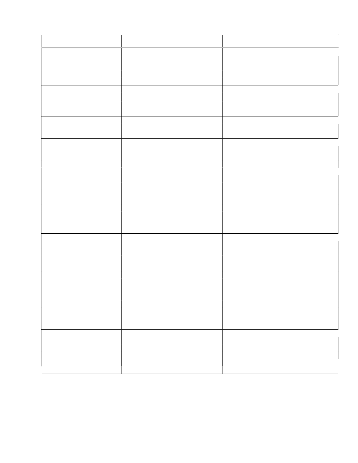
PROBLEM POSSIBLE CAUSE POSSIBLE SOLUTIONS
Lights A. Blown Fuse A. Investigate cause, replace Fuse
Heating System B. Circuit Breaker "off" B. Investigate cause, replace Breaker
Humidity System C. Heat Switch & Light Switch C. Place Heat Switch and/or Light
Not Operating in "off" position Switch to "on" position
D. Case Fuse Blown D. Investigate cause, and replace Fuse
Lights Inoperative- A. Light Switch in "off" position A. Place Light Switch in "on" position
Heating & Humidity B. Faulty or disconnected Light B. Check & if necessary, replace Heat
Systems Operative Switch Switch
C. Burnt Out Bulb(s) C. Replace Bulb(s)
Lights Operative A. Heat Switch in "off" position A. Place Heat Switch in "on" position
Heating & Humidity B. Faulty or disconnected Heat B. Check & if necessary, replace Heat
Systems Inoperative Switch Switch
Heating System Inoperative A. Faulty, disconnected, or A. Check & if necessary, replace
Blower Motor Not Operating jammed Blower Motor Blower Motor
Lights & Humidity
System Operative
Insufficient or No Heat A. Temperature Control set too low A. Adjust Heat Control clockwise
Blower Motor Operative B. Doors open B. Allow doors to remain closed until
Lights & Humidity Operative
temperature reaches proper level
C. Faulty or disconnected C. Check & replace, if necessary
Temperature Control
D. Faulty or Disconnected D. Check operation of each Heater &
Heater replace if necessary
E. Dirty or dislocated Temperature E. Clean & check location of Temperature
Control Probe in Heat Duct Control Probe
Humidity System A. Humidity Switch set too low A. Adjust Humidity Control counter clock-
Inoperative or Inadequate
wise to higher position
Lights Operative B. Doors open B. Allow doors to remain closed until
Heating System Operative
humidity reaches proper level
C. Water Pan empty C. Refill Water Pan
D. Disconnected Water Pan D. Connect Water Pan Plug to plug
Power Cord receptacle inside of Control Box
E. Faulty or disconnected Water E. Check & replace, if necessary
Heater Relay
F. Faulty or disconnected Water F. Check & replace, if necessary
Heater Element
G. Faulty or dirty Water Level Float G. Check and clean Water Level Float
Switch Switch
Low Water Light "ON" A. Water Pan empty A. Refill Water Pan
B. Water Level Float Switch B. Remove Float from stem by removing
Installed upside down clip, rotate ends on Float Switch,
reinstall clip
Temperature Indicator A. Dirty or dislocated temperature A. Clean & check location of probe in
probe ductwork

-
25
-
Special Service Situations
If moisture or liquid is observed around or under a Federal Industries case, an immediate
investigation should be made by qualified personnel to determine the source of the moisture or
liquid. The investigation made should determine if the case is malfunctioning or if there is a
simple housekeeping problem.
Moisture or liquid around or under a case is a potential slip/fall hazard for persons walking by or
working in the general area of the case. Any case malfunction or housekeeping problem that
creates a slip/fall hazard around or under a case should be corrected immediately.
SALE & DISPOSAL
Owner Responsibility
If you sell or give away your Federal Industries case you must make sure that all safety labels and
the Installation-Service Manual are included with it. If you need replacement labels or manuals,
Federal Industries will provide them free of charge. Contact the customer service department at
Federal Industries at (800) 356-4206.
The customer service department at Federal Industries should be contacted at the time of sale or
disposal of your case so records may be kept of its new location.
-
26
-
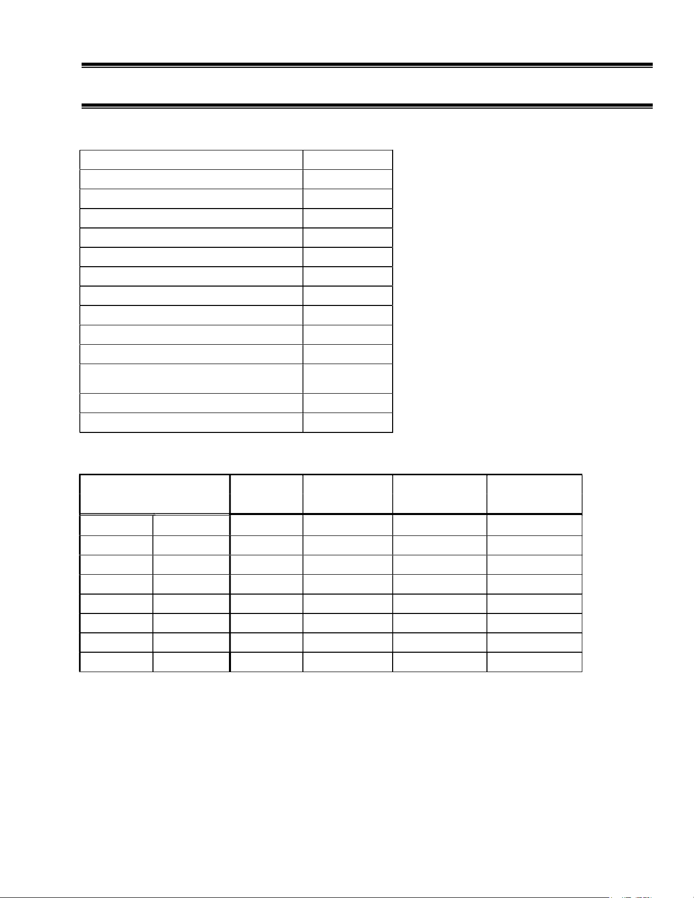
ELECTRICAL DATA
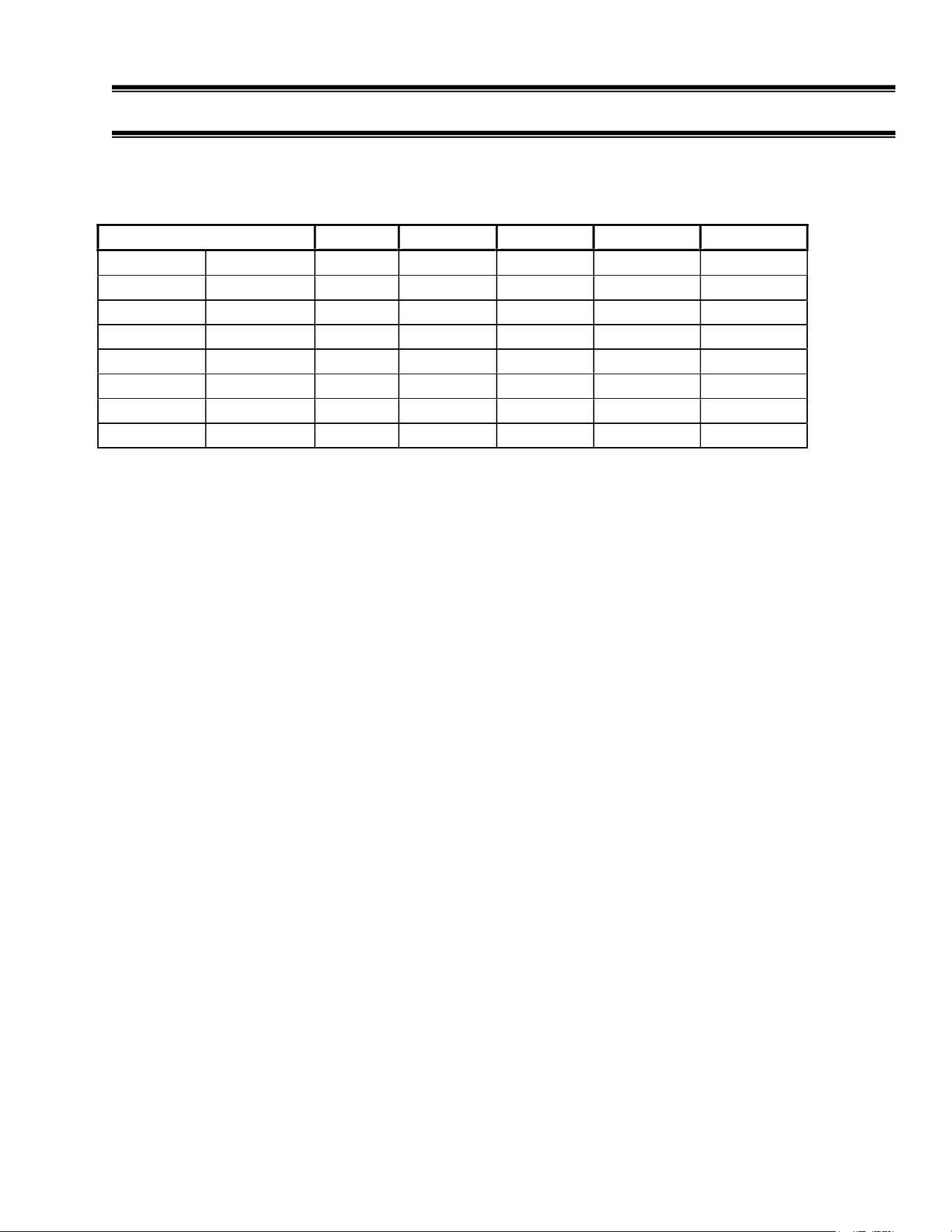
All models require 120 Volt, 1 Phase, 60 Hertz electrical circuit.
ELECTRICAL DATA
-
AMPS
LIGHTS
FAN MOTOR
AIR HEATER
WATER HEATER
TOTAL AMPS
CG3642HDP SG3642HDP 3.0 1.5 9.8 6.2 20.5
CG3648HDP SG3648HDP 4.0 1.5 9.8 6.2 21.4
CG5042HDP SG5042HDP 4.5 1.5 9.8 6.2 22.0
CG5048HDP SG5048HDP 6.0 1.5 9.8 6.2 23.5
CG5942HDP SG5942HDP 4.5 1.5 9.8 6.2 22.0
CG5948HDP SG5948HDP 6.0 1.5 9.8 6.2 23.5
CG7742HDP SG7742HDP 7.5 1.5 9.8 6.2 25.0
CG7748HDP SG7748HDP 10.0 1.5 9.8 6.2 27.5
Refer to the data plate attached to rear of the case for electrical requirements.
-
27
-
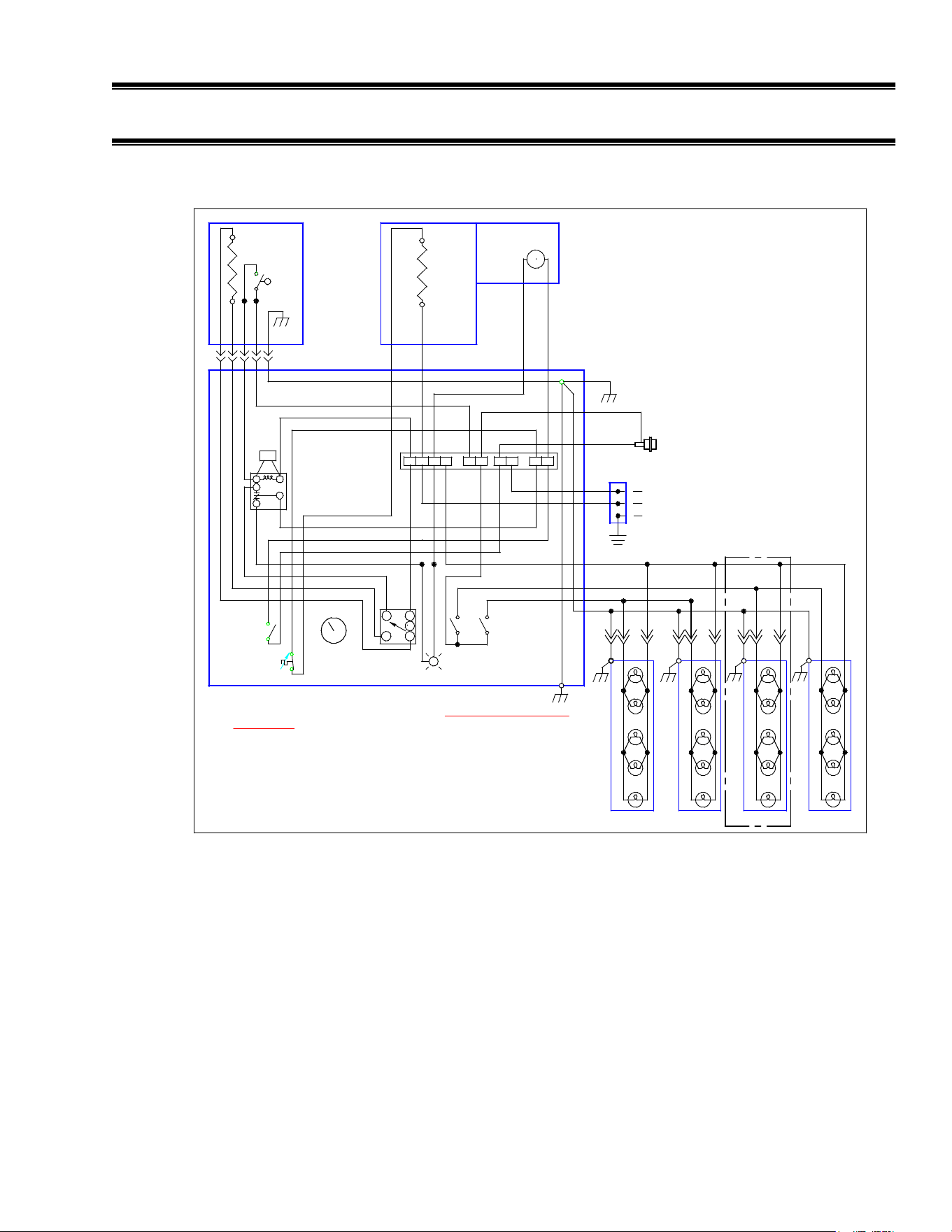
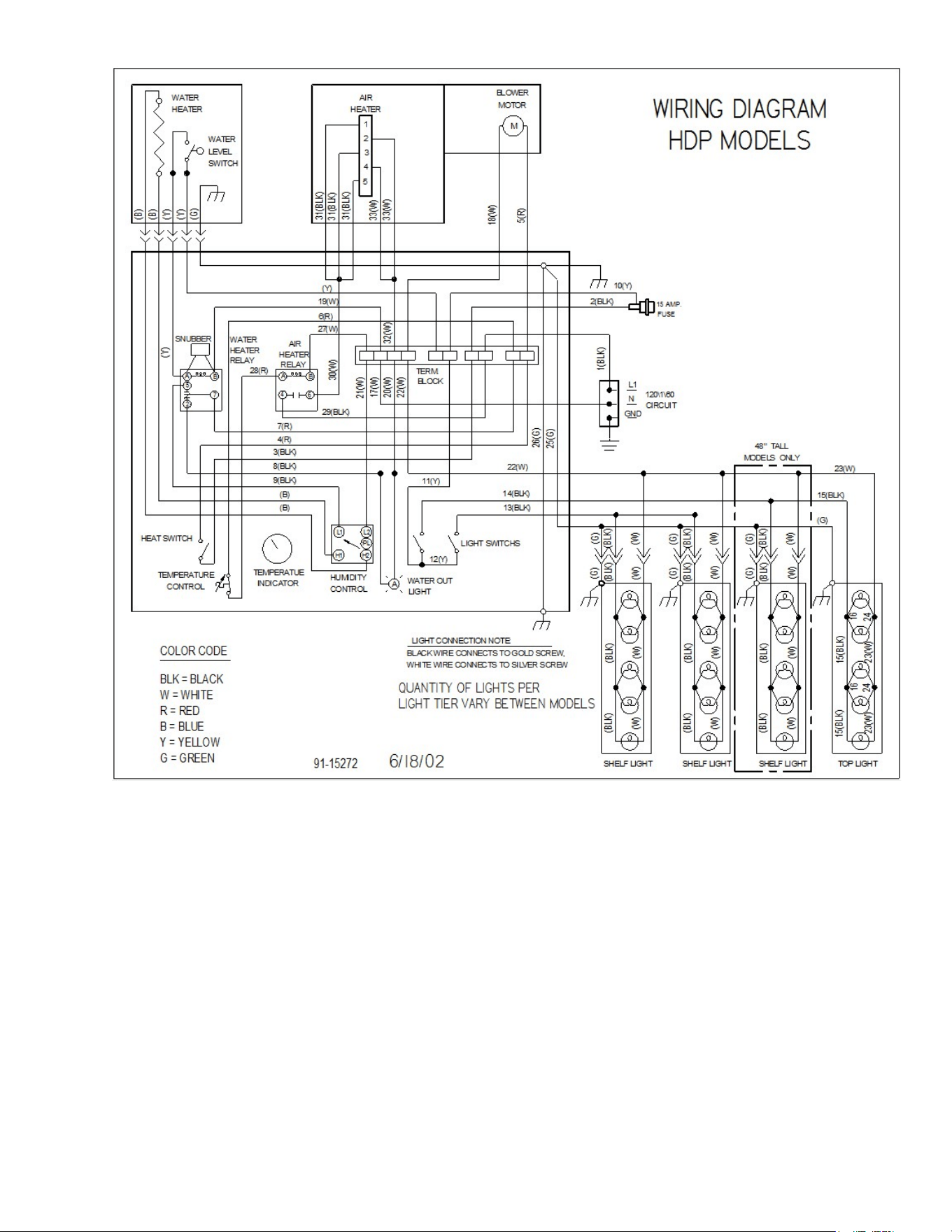
MAIN WIRING DIAGRAMS
COLOR CODE
BLK = BLACK
W = WHITE
R = RED
B = BLUE
Y = YELLOW
G = GREEN
5/12/00
91-15272
PL
H2H1
L1 L2
A
HEAT SWITCH
TEMPERATURE
CONTROL
TEMPERATUE
INDICATOR
HUMIDITY
CONTROL
WATER OUT
LIGHT
LIGHT SWITCHS
B
A
5
7
2
M
48" TALL
MODELS ONLY
120\1\60
CIRCUIT
WATER
HEATER
WATER
LEVEL
SWITCH
AIR
HEATER
BLOWER
MOTOR
WATER
HEATER
RELAY
TERM.
BLOCK
L1
N
GND
(Y)
(Y)
(G)
(B)
(B)
7(R)
4(R)
3(BLK)
8(BLK)
9(BLK)
(B)
(B)
19(W)
22(W)
(BLK)
5(R)
10(Y)
(Y)
6(R)
17(W)
1(BLK)
21(W)
22(W)
(Y)
(G)
SHELF LIGHT
12(Y)
BLACK WIRE CONNECTS TO GOLD SCREW,
WHITE WIRE CONNECTS TO SILVER SCREW
LIGHT CONNECTION NOTE:
26(G)
25(G)
SNUBBER
FUSE
15 AMP.
TOP LIGHTSHELF LIGHT SHELF LIGHT
15(BLK)
23(W)
16
(G)
15(BLK)
(BLK)
(W)
(BLK)
(W)
(BLK)
(W)
(BLK)
(W)
(W)
(BLK)
(W)
(BLK)
(G)
(G)
(G) (G)
(G) (G)
QUANTITY OF LIGHTS PER
LIGHT TIER VARY BETWEEN MODELS
WIRING DIAGRAM
HDP MODELS
18(W)
(BLK)
(W)
(BLK)
(W)
(BLK)
(W)
(BLK)
(W)
(BLK)
(W)
(BLK)
(W)
11(Y)
16
15(BLK)
13(BLK)
23(W)
24
24
(BLK)
23(W)
2(BLK)
20(W)
-
28
-
-
29
-
REPLACEMENT PARTS
ELECTRICAL COMPONENTS (ALL HDP MODELS)
LIGHT & HEAT SWITCH
41
-
11066
TEMPERATURE CONTROL THERMOSTAT
41
-
12410
TEMPERATURE INDICATOR
32
-
12452
HUMIDITY CONTROL
41
-
10925
AMBER PILOT LIGHT
42
-
11327
FUSE (SC
-
15 TIME DELAY)
41
-
12326
FUSE HOLDER
41
-
30513
BLOWER MOTOR
41
-
11325
AIR HEATER
40
-
15256
WATER HEATER
40
-
12323
LIQUID LEVEL FLOAT SWITCH
41
-
11331
RELAY SPDT 13 AMP
WATER
RELAY SPST 15 AMP
AIR
41
-
11357
41
-
11324
LIGHT BULB
42
-
11248
WIRING DIAGAM
91
-
15272
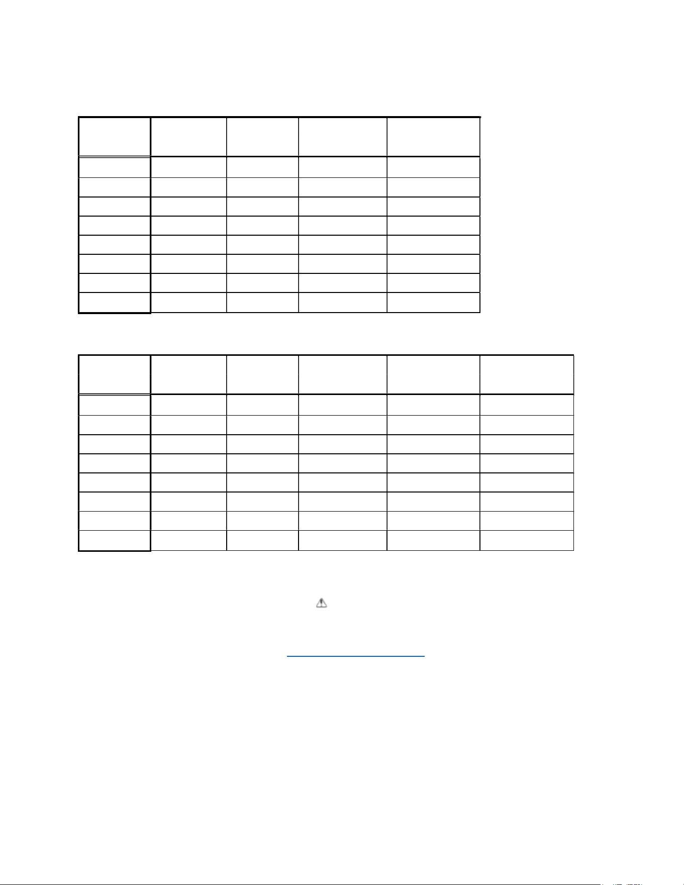
DOOR & SHELF COMPONENTS
MODELS
DOOR LEFT
DOOR RIGHT
DOOR LEFT
DOOR RIGHT
CLEAR
CLEAR
REFLECTIVE
REFLECTIVE
CGR3642
SGR3642
53
-
13666
53
-
13667
53
-
13682
53
-
13683
CGR3648
SGR3648
53
-
13674
53
-
13675
53
-
13690
53
-
13691
CGR5042
SGR5042
53
-
13668
53
-
13669
53
-
13684
53
-
13685
CGR5048
SGR5048
53
-
13676
53
-
13677
53
-
13692
53
-
13693
CGR5942
SGR5942
53
-
13676
53
-
13677
53
-
13692
53
-
13693
CGR5948
SGR5948
53
-
13676
53
-
13677
53
-
13692
53
-
13693
CGR7742
SGR7742
53
-
13672
53
-
13673
53
-
13688
53
-
13689
CGR7748
SGR7748
53
-
13680
53
-
13681
53
-
13696
53
-
13697
-
30
-
GLASS COMPONENTS CURVED
MODELS
CURVED
END GLASS
END GLASS
END GLASS
FRONT GLASS
CLEAR
REFLECTIVE L.H.
REFLECTIVE R.H.
CG3642HDP
50
-
13382
51
-
13470
51
-
14401
-
L
51
-
14401
-
R
CG3648HDP
50
-
13387
51
-
13471
51
-
14402
-
L
51
-
14402
-
R
CG5042HDP
50
-
13383
51
-
13470
51
-
14401
-
L
51
-
14401
-
R
CG5048HDP
50
-
13388
51
-
13471
51
-
14402
-
L
51
-
14402
-
R
CG5942HDP
50
-
13384
51
-
13470
51
-
14401
-
L
51
-
14401
-
R
CG5948HDP
50
-
13389
51
-
13471
51
-
14402
-
L
51
-
14402
-
R
CG7742HDP
50
-
13385
51
-
13470
51
-
14401
-
L
51
-
14401
-
R
CG7748HDP
50
-
13390
51
-
13471
51
-
14402
-
L
51
-
14402
-
R
GLASS COMPONENTS STRAIGHT
MODELS
FRONT
TOP
END GLASS
END GLASS
END GLASS
GLASS
GLASS
CLEAR
REFLECTIVE L.H.
REFLECTIVE R.H.
SG3642HDP
51
-
13403
51
-
13404
51
-
13421
51
-
13401
-
L
51
-
13401
-
R
SG3648HDP
51
-
13407
51
-
13408
51
-
13422
51
-
13402
-
L
51
-
13402
-
R
SG5042HDP
51
-
13409
51
-
13410
51
-
13421
51
-
13401
-
L
51
-
13401
-
R
SG5048HDP
51
-
13411
51
-
13412
51
-
13422
51
-
13402
-
L
51
-
13402
-
R
SG5942HDP
51
-
13413
51
-
13414
51
-
13421
51
-
13401
-
L
51
-
13401
-
R
SG5948HDP
51
-
13415
51
-
13416
51
-
13422
51
-
13402
-
L
51
-
13402
-
R
SG7742HDP
51
-
13417
51
-
13418
51
-
13421
51
-
13401
-
L
51
-
13401
-
R
SG7748HDP
51
-
13419
51
-
13420
51
-
13422
51
-
13402
-
L
51
-
13402
-
R
California Residents Only.
WARNING
This product can expose you to chemicals including chromium which is known to the State of California
to cause cancer and birth defects or other reproductive harm. For more information go to
www.P65Warnings.ca.gov