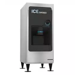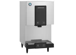
Models
DB-130H
DBW-130H
DB-200H
DBW-200H
Ice Dispenser
Instruction Manual
Issued: 10-24-2025
Revised: 4-28-2026
hoshizakiamerica.com
2
WARNING
Only qualied service technicians should install and service the appliance. To
obtain the name and phone number of your local Hoshizaki Certied Service
Representative, visit www.hoshizakiamerica.com. No installation, operation, or
maintenance should be undertaken until the technician has thoroughly read this
Instruction Manual. No service should be undertaken until the technician has
thoroughly read the service manual available at www.hoshizakiamerica.com.
Likewise, the owner/manager should not proceed to operate the appliance until the
installer has instructed them on its proper operation. Failure to install, operate, and
maintain the appliance in accordance with this manual will adversely affect safety,
performance, component life, and warranty coverage and may result in costly water
damage. Proper installation is the responsibility of the installer. Product failure or
property damage due to improper installation is not covered under warranty.
Hoshizaki provides this manual primarily to assist qualied service technicians in the
installation, maintenance, and service of the appliance.
Should the reader have any questions or concerns which have not been satisfactorily
addressed, please call, send an e-mail message, or write to the Hoshizaki Technical
Support Department for assistance.
Phone: 1-800-233-1940; (770) 487-2331
E-mail: tech-suppor[email protected]
618 Highway 74 South
Peachtree City, GA 30269
Attn: Hoshizaki Technical Support Department
NOTE: To expedite assistance, all correspondence/communication MUST include the
following information:
• Model Number
• Serial Number
• Complete and detailed explanation of the problem.
3
IMPORTANT
This manual should be read carefully before the appliance is installed and operated.
Read the warnings and guidelines contained in this manual carefully as they
provide essential information for the continued safe use and maintenance of the
appliance. Retain this manual for any further reference that may be necessary
CONTENTS
Important Safety Information ................................................................................................. 4
I. Specications ...................................................................................................................... 6
A. Electrical Data ............................................................................................................... 6
B. Dimensions/Connections .............................................................................................. 7
1a. DB-130H ................................................................................................................ 7
1b. DBW-130H ............................................................................................................. 8
2a. DB-200H ................................................................................................................ 9
2b. DBW-200H ........................................................................................................... 10
II. Installation Instructions .....................................................................................................11
A. Location .......................................................................................................................11
B. Checks Before Installation ........................................................................................... 12
C. How to Remove Panels ............................................................................................... 12
D. Setup ........................................................................................................................... 13
E. Electrical Connection .................................................................................................. 15
F. Water Supply and Drain Connections .......................................................................... 16
G. Final Checklist ............................................................................................................ 19
III. Operating Instructions ..................................................................................................... 20
A. Startup ........................................................................................................................ 20
IV. Maintenance ................................................................................................................... 21
A. Maintenance Schedule ................................................................................................ 22
B. Cleaning and Sanitizing Instructions ........................................................................... 23
V. Preparing the Appliance for Periods of Non-Use ............................................................. 26
VI. Disposal .......................................................................................................................... 27
4
Important Safety Information
Throughout this manual, notices appear to highlight attention to situations that can result in
death, serious injury, and damage to the appliance or property.
WARNING
Indicates a hazardous situation that, if not avoided, could result in
death or serious injury.
NOTICE
Indicates a situation that, if not avoided, could result in damage to
the appliance or property.
IMPORTANT
Indicates important information about the use and care of the
appliance.
WARNING
The appliance should be destined only to the use for which it has been expressly
conceived. Any other use should be considered improper and therefore dangerous.
The manufacturer cannot be held responsible for injury or damage resulting from
improper, incorrect and unreasonable use. Failure to install, operate and maintain the
appliance in accordance with this manual will adversely affect safety, performance,
component life and warranty coverage, and may result in costly water damage.
To reduce the risk of death, electric shock, serious injury, or re, follow basic
precautions including the following:
• Only qualied service technicians should install and service the appliance.
• The appliance must be installed in accordance with applicable national, state, and
local codes and regulations.
• Electrical connection must be hard-wired and must meet national, state, and local
electrical code requirements. Failure to meet these code requirements could result in
death, electric shock, serious injury, re, or damage.
• The appliance requires an independent power supply of proper capacity.
See the nameplate for electrical specications. Failure to use an independent power
supply of proper capacity can result in a tripped breaker, blown fuse, damage to
existing wiring, or component failure. This could lead to heat generation or re.
• This ice dispenser is designed and intended to be used with an appropriate Hoshizaki
modular crescent cuber icemaker, including models utilizing R-290 refrigerant. The use
of this ice dispenser in combination with any icemaker other than a Hoshizaki modular
crescent cuber icemaker cannot be recommended.
• THE APPLIANCE MUST BE GROUNDED. Failure to properly ground the appliance
could result in death or serious injury.
• Turn off the power supply before servicing. Lockout/Tagout to prevent the power supply
from being turned back on inadvertently.
• Appliance is heavy. Use care when lifting or positioning. Work in pairs when needed to
prevent injury or damage.
• Do not make any alterations to the appliance. Alterations could result in electric shock,
injury, re, or damage to the appliance.
5
WARNING, continued
• The appliance is not intended for use by persons (including children) with reduced
physical, sensory, or mental capabilities, or lack of experience and knowledge, unless
they have been given supervision or instruction concerning use of the appliance by a
person responsible for their safety.
• Do not splash, pour, or spray water directly onto or into the appliance. This might cause
short circuit, electric shock, corrosion, or failure.
• Children should be supervised to ensure that they do not play with the appliance.
• Do not climb, stand, or hang on the appliance or allow children or animals to do so.
Serious injury could occur or the appliance could be damaged.
• Do not use combustible spray or place volatile or ammable substances in or near the
appliance. They might catch re.
• Keep the area around the appliance clean. Dirt, dust, or insects in the appliance could
cause harm to individuals or damage to the appliance.
NOTICE
• Follow the inlet water connection, drain line connection, and maintenance instructions
carefully to reduce the risk of costly water damage.
• In areas where water damage is a concern, install in a contained area with a oor
drain.
• Install the appliance in a location that stays above freezing. Normal operating ambient
temperature must be between 45°F to 100°F (7°C to 38°C).
• Level the ice dispenser prior to installing the icemaker. After icemaker installation,
conrm the icemaker is level. An out-of-level icemaker could result in improper
operation, poor performance, water leaks, and/or damage to the icemaker.
• Do not leave the appliance on during extended periods of non-use, extended absence,
or in sub-freezing temperatures. To properly prepare the appliance for these occasions,
follow the instructions in "V. Preparing the Appliance for Periods of Non-Use."
• If water collects in the bin and will not drain, turn off the appliance and close the water
supply line shut-off valve. Call for service.
• The ice dispenser is for ice use only. Do not store anything else in the ice dispenser.
• Protect the oor when moving the appliance to prevent damage to the oor.
6
I. Specications
A. Electrical Data
The nameplate provides electrical data. The nameplate is located on the rear panel.
For certication marks, see the nameplate.
We reserve the right to make changes in specications and design without prior notice.
Model Number DB-130H DBW-130H DB-200H DBW-200H
AC Supply Voltage 115/60/1 115/60/1 115/60/1 115/60/1
Amperes 1.4 AMPS 1.4 AMPS 1.4 AMPS 1.4 AMPS
Maximum Fuse Size 15 AMPS 15 AMPS 15 AMPS 15 AMPS
Max. HACR Breaker
(USA Only)
15 AMPS 15 AMPS 15 AMPS 15 AMPS
Max. Circuit Breaker
(Canada Only)
15 AMPS 15 AMPS 15 AMPS 15 AMPS
Minimum Circuit
Ampacity
15 AMPS 15 AMPS 15 AMPS 15 AMPS
7
B. Dimensions/Connections
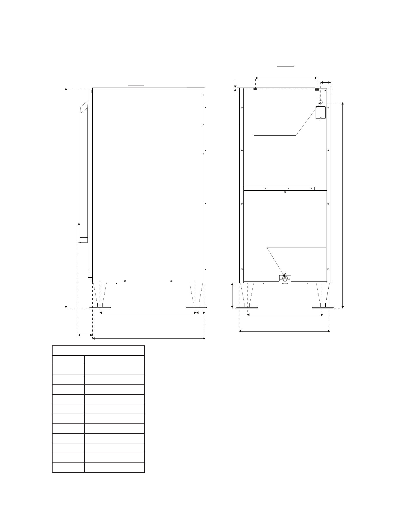
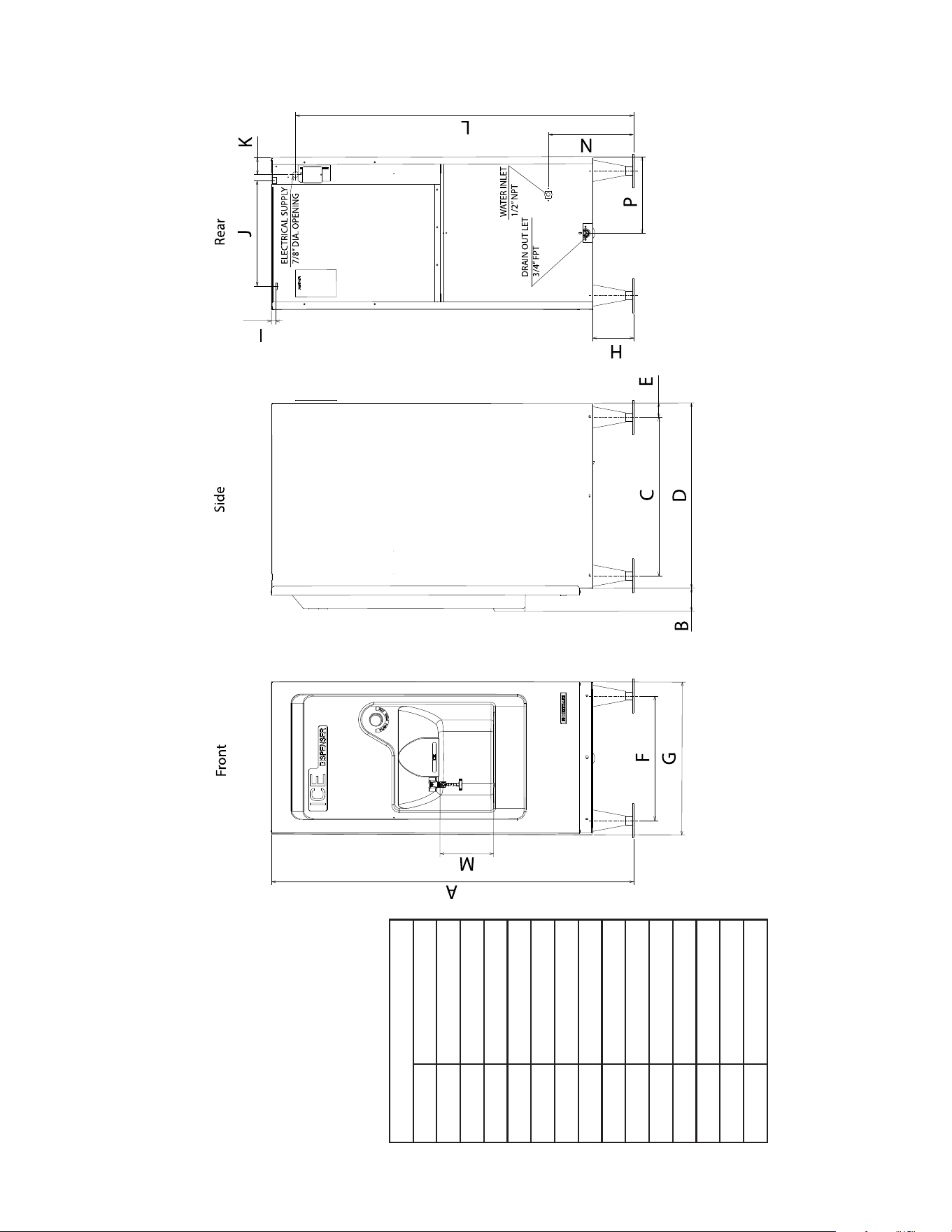
1a. DB-130H
Power Supply
Drain Outlet 3/4" FPT
A
B
C
D
E
F
G
H
I
J
K
L
Side
Rear
DB-130H
A 1346 (53)
B 73 (2-7/8)
C 589 (23-1/4)
D 684 (26-7/8)
E 48 (1-7/8)
F 457 (18)
G 558 (22)
H 155 (6-1/8)
I 13 (1/2)
J 395 (15-1/2)
K 61 (2-3/8)
L 1260 (49-5/8)
Units: mm (in.)
8
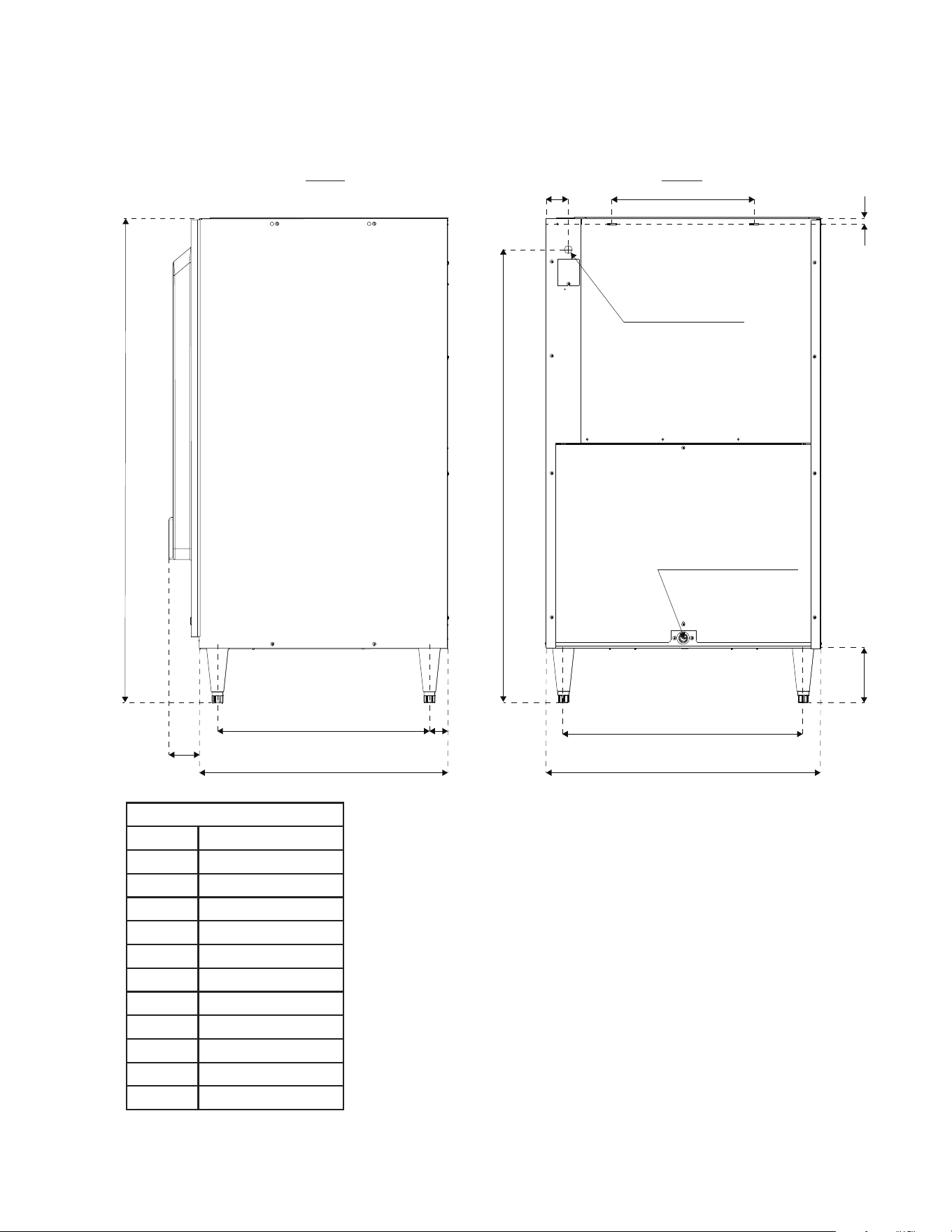
1b. DBW-130H
Units: mm (in.)
DBW-130H
A 1348 (53 1/8)
B 86 (3 3/8)
C 589 (23 1/4)
D 689 (27 1/8)
E 53 (2 1/8)
F 464 (18 1/4)
G 568 (22 3/8)
H 152 (6)
I 16 (5/8)
J 392 (15 3/8)
K 63 (2 1/2)
L 1258 (49 1/2)
M 200 (8)
N 200 (7 7/8)
P 166 (6 1/2)
9
2a. DB-200H
Power Supply
A
B
C
D
E
F
G
H
I
J
K
L
Drain Outlet 3/4" FPT
Side Rear
Units: mm (in.)
DB-200H
A 1346 (53)
B 73 (2-7/8)
C 589 (23-1/4)
D 684 (26-7/8)
E 48 (1-7/8)
F 666 (26-1/4)
G 762 (30)
H 152 (6)
I 13 (1/2)
J 395 (15-1/2)
K 61 (2-3/8)
L 1260 (49-5/8)
10
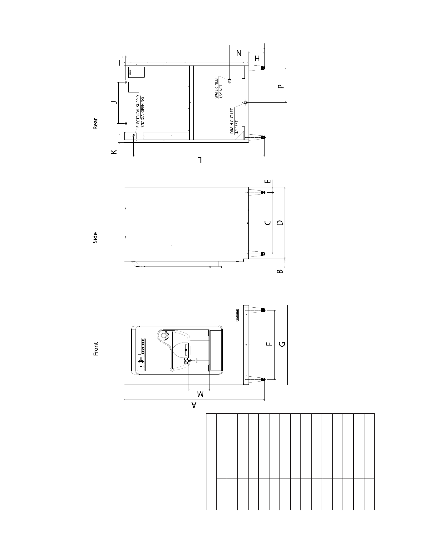
Units: mm (in.)
DBW-200H
A 1348 (53 1/8)
B 86 (3 3/8)
C 589 (23 1/4)
D 687 (27 1/8)
E 51 (2)
F 666 (26 1/4)
G 762 (30)
H 152 (6)
I 17 (5/8)
J 395 (15 1/2)
K 63 (2 1/2)
L 1258 (49 1/2)
M 200 (8)
N 181 (7 1/8)
P 382 (15)
2b. DBW-200H
11
II. Installation Instructions
WARNING
• The appliance must be installed in accordance with applicable national, state, and
local codes and regulations.
• Failure to install, operate, and maintain the appliance in accordance with this
manual will adversely affect safety, performance, component life, and warranty
coverage and may result in costly water damage.
• CHOKING HAZARD: Ensure that all components, fasteners, and thumbscrews are
securely in place after installation. Verify that none have fallen into the ice dispenser.
A. Location
NOTICE
• The appliance is not intended for outdoor use. Normal operating ambient
temperature must be between 45°F to 100°F (7°C to 38°C). Operation of the ice
dispenser for extended periods outside of this temperature range may affect ice
dispenser performance.
• The appliance will not work at sub-freezing temperatures. To prevent damage to the
water supply line, drain the appliance if the air temperature is going to go below
32°F (0°C). See "V. Preparing the Appliance for Periods of Non-Use."
• The appliance should not be located next to ovens, grills, or other high heat producing
equipment.
• Allow 6" (15 cm) clearance at rear, sides, and top for proper air circulation and ease
of maintenance and/or service should they be required. Ensure that the icemaker's
clearance requirements are met. Note that more space may be needed on the left side
of the DB-130H and DBW-130H and on the right side of the DB-200H and
DBW-200H for service of the drive system.
• The location should provide a rm and level foundation for the equipment.
• Always avoid a site where dripping is not allowed.
12
B. Checks Before Installation
NOTICE
• The DB-130H, DB-200H, DBW-130H, and DBW-200H ice dispenser is designed
and intended to be used with an appropriate Hoshizaki modular crescent cuber
icemaker, including models utilizing R-290 refrigerant.
• The DB-130H and DBW-130H ice dispensers are designed for use with a 22"
Hoshizaki modular crescent cuber icemaker and the DB-200H and DBW-200H ice
dispensers are designed for use with a 22" or 30" Hoshizaki modular crescent cuber
icemaker. The use of this ice dispenser in combination with any icemaker other than
a Hoshizaki modular crescent cuber icemaker cannot be recommended.
• Visually inspect the exterior of the shipping container and immediately report any
damage to the carrier. Upon opening the container, any concealed damage should also
be immediately reported to the carrier.
• Remove the shipping carton, tape, and packing material. If any are left in the appliance,
it will not work properly.
• See the nameplate on the rear panel, and check that your voltage supplied corresponds
with the voltage specied on the nameplate.
• Remove the front panel to prevent damage when installing the appliance. Remove the
left and right side panels. See "II.C. How to Remove Panels."
• Remove the package containing the accessories.
• Remove the protective plastic lm from the panels. If the ice dispenser is exposed to the
sun or to heat, remove the lm after the ice dispenser cools.
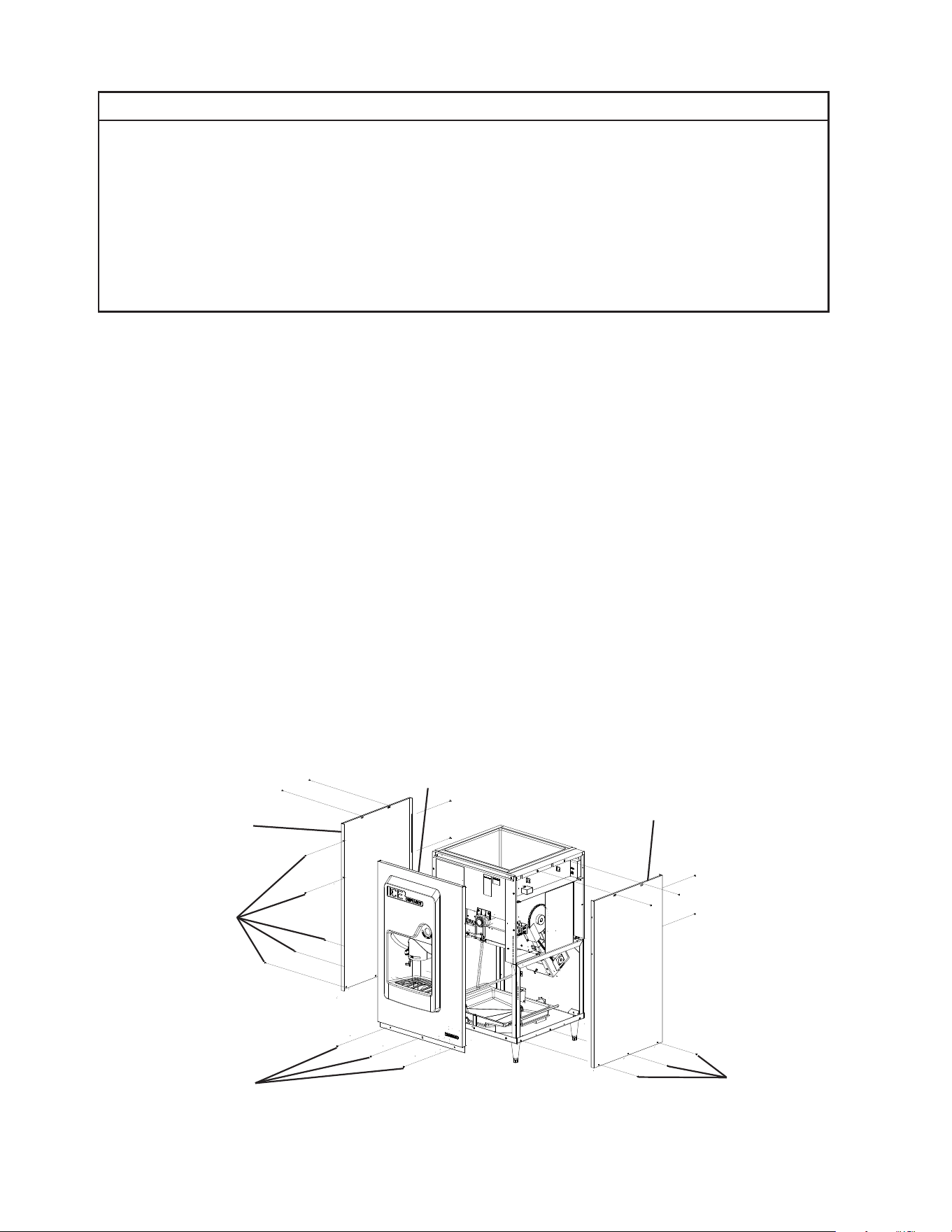
C. How to Remove Panels
• Front Panel: Remove the screws. Lift up and towards you. See Fig. 1.
• Side Panels: Remove the screws. Lift off.
Fig. 1
Model shown: DBW-200H
Screws
Side Panel
Front Panel
Side Panel
Screws
Screws
13
D. Setup
WARNING
The installer must ensure the ice dispenser is compatible with the icemaker, and
the ice dispenser and icemaker are properly attached and secured.
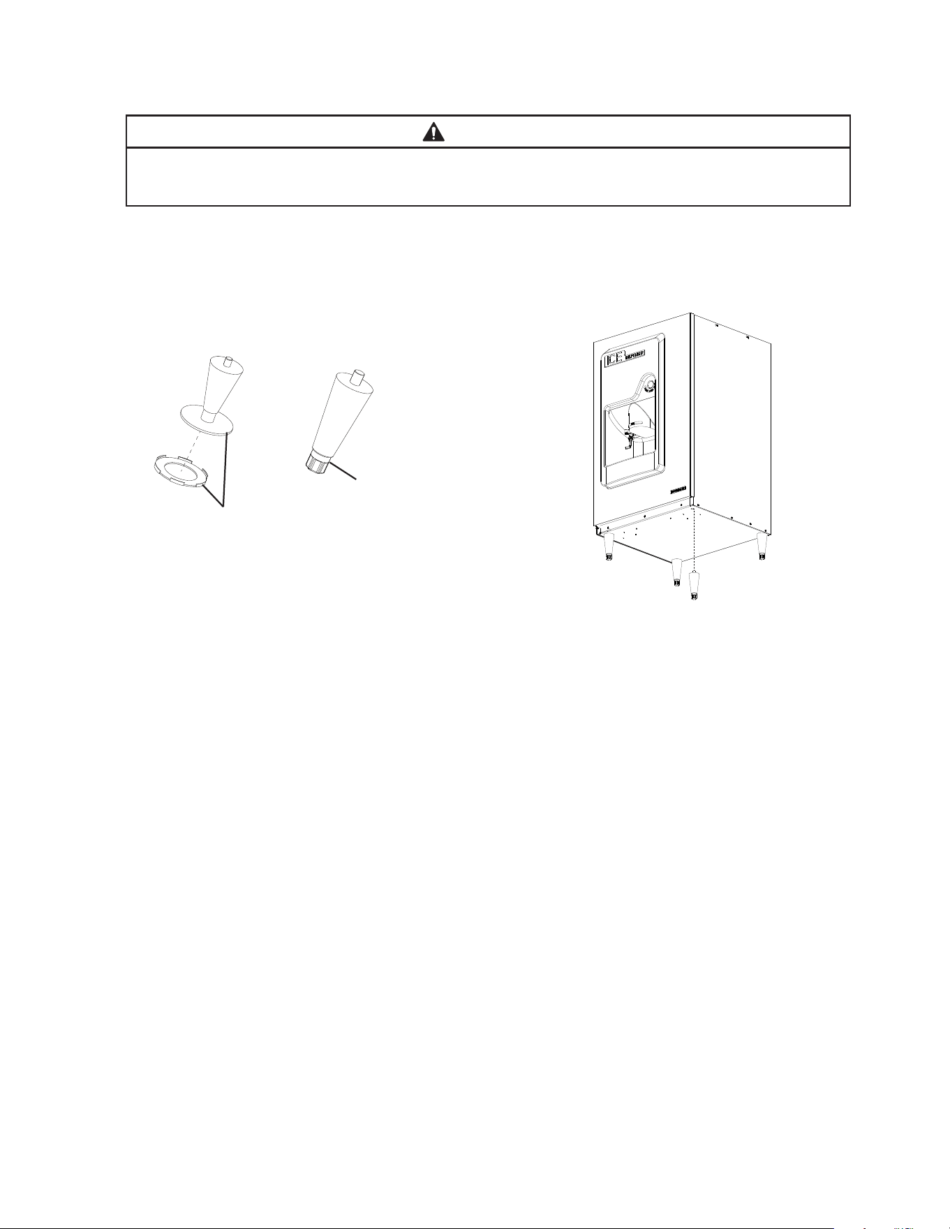
1. Ice Dispenser Setup
1) Attach the 4 adjustable legs to the bottom of the appliance. See Figs. 2 and 3.
Fig. 3
Model shown: DBW-200H
Fig. 2
DB/DBW-130H
DB/DBW-200H
2) Position the appliance in its permanent location. Clean and wipe the interior with a
clean cloth.
3) Adjust the legs to level the appliance in both the left-to-right and front-to-rear directions.
14
2. Icemaker Installation on Top of Ice Dispenser
4) If required, install an adapter kit or top kit. Contact your local Hoshizaki distributor
for recommendations. NOTICE! Use care to avoid damage to ice dispenser unit
components when attaching kits.
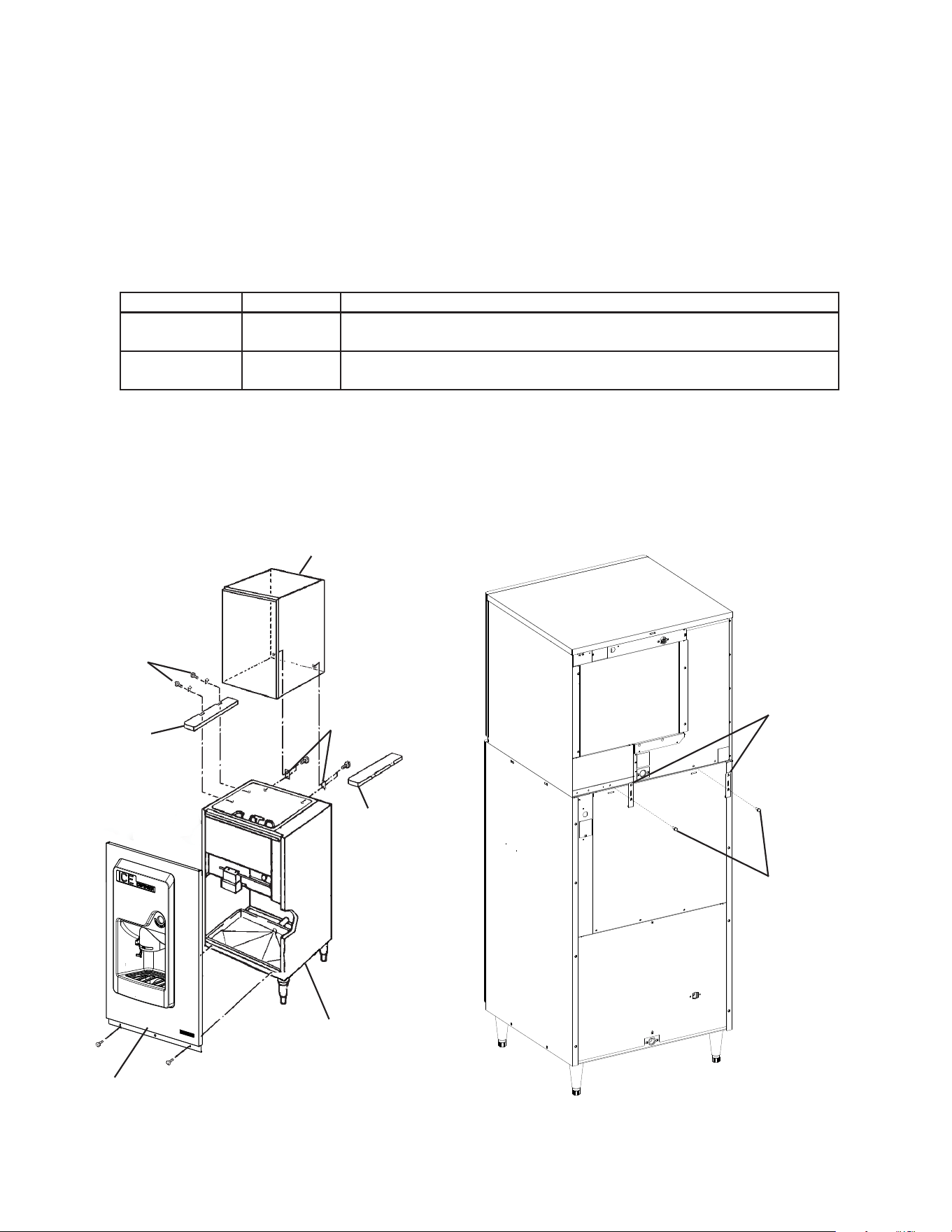
5) Place the icemaker on top of the ice dispenser, then secure the icemaker to the ice
dispenser using the 2 universal braces and hex head bolts included with the icemaker.
See Fig. 4. Conrm the setup is level.
The recommended icemakers are listed below:
Model Number Width Recommended Hoshizaki Icemaker
DB-130H
DBW-130H
22" Wide 22" Hoshizaki modular crescent cuber icemaker
DB-200H
DBW-200H
30" Wide 22" or 30" Hoshizaki modular crescent cuber icemaker
For further options, contact your local Hoshizaki distributor.
6) Follow the setup instructions in the icemaker instruction manual to complete icemaker
installation. Continue to "E. Electrical Connection" for ice dispenser installation.
Icemaker
Ice
Dispenser
Mounting
Brackets
Hex Head
Screws
Fig. 4
Models shown: DBW-200H with KMD-705MAJ Icemaker
Top Kit
(DBW-200H option)
Icemaker
Hex Head
Screws
Left Side
Top Kit
Right Side
Top Kit
Ice Dispenser
Front Panel
Mounting
Brackets
15
E. Electrical Connection
WARNING
• Electrical connection must be hard-wired and must meet national, state, and local
electrical code requirements. Failure to meet these code requirements could result in
death, electric shock, serious injury, re, or damage.
• The appliance requires an independent power supply of proper capacity.
See the nameplate for electrical specications. Failure to use an independent power
supply of proper capacity can result in a tripped breaker, blown fuse, damage to
existing wiring, or component failure. This could lead to heat generation or re.
• THE APPLIANCE MUST BE GROUNDED. Failure to properly ground the ice
dispenser could result in death or serious injury.
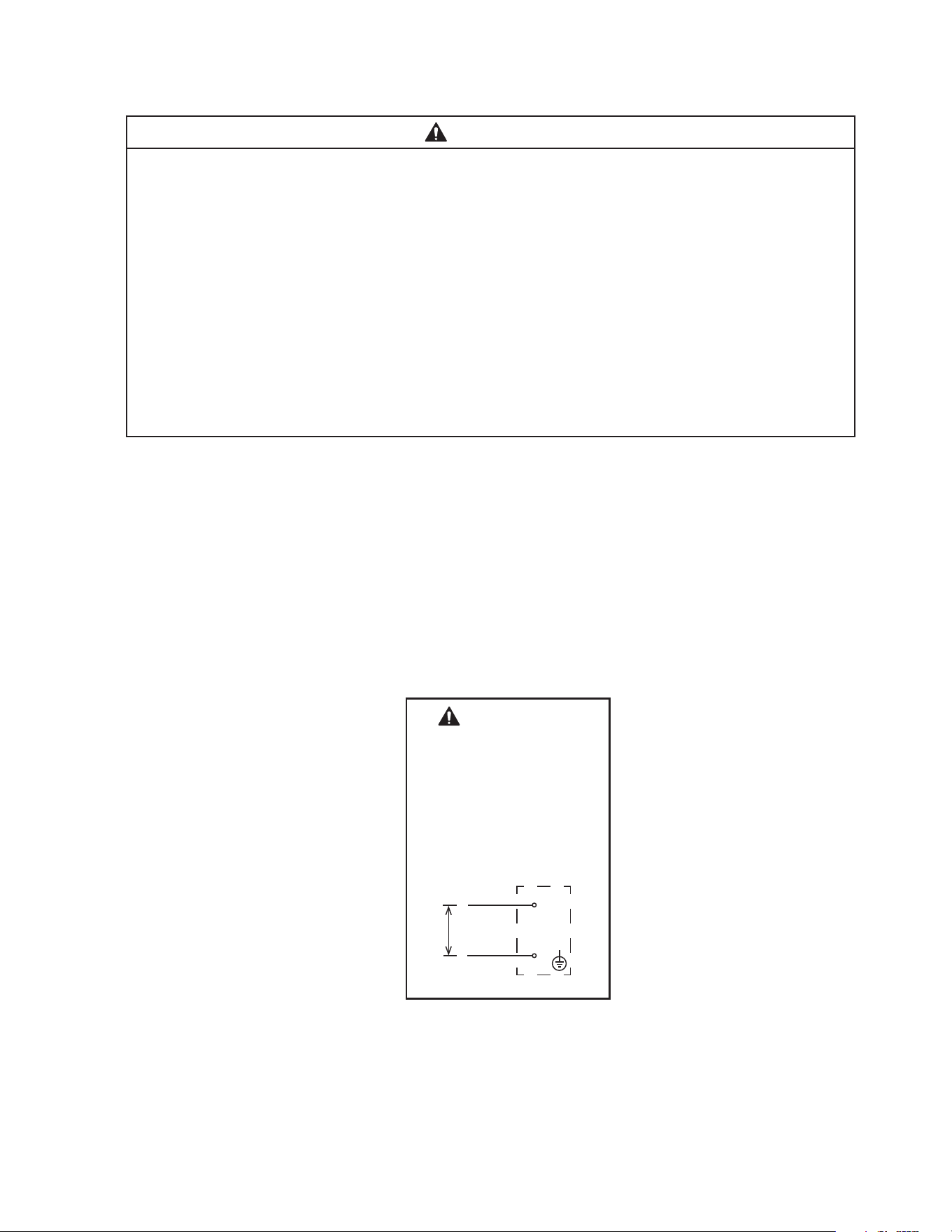
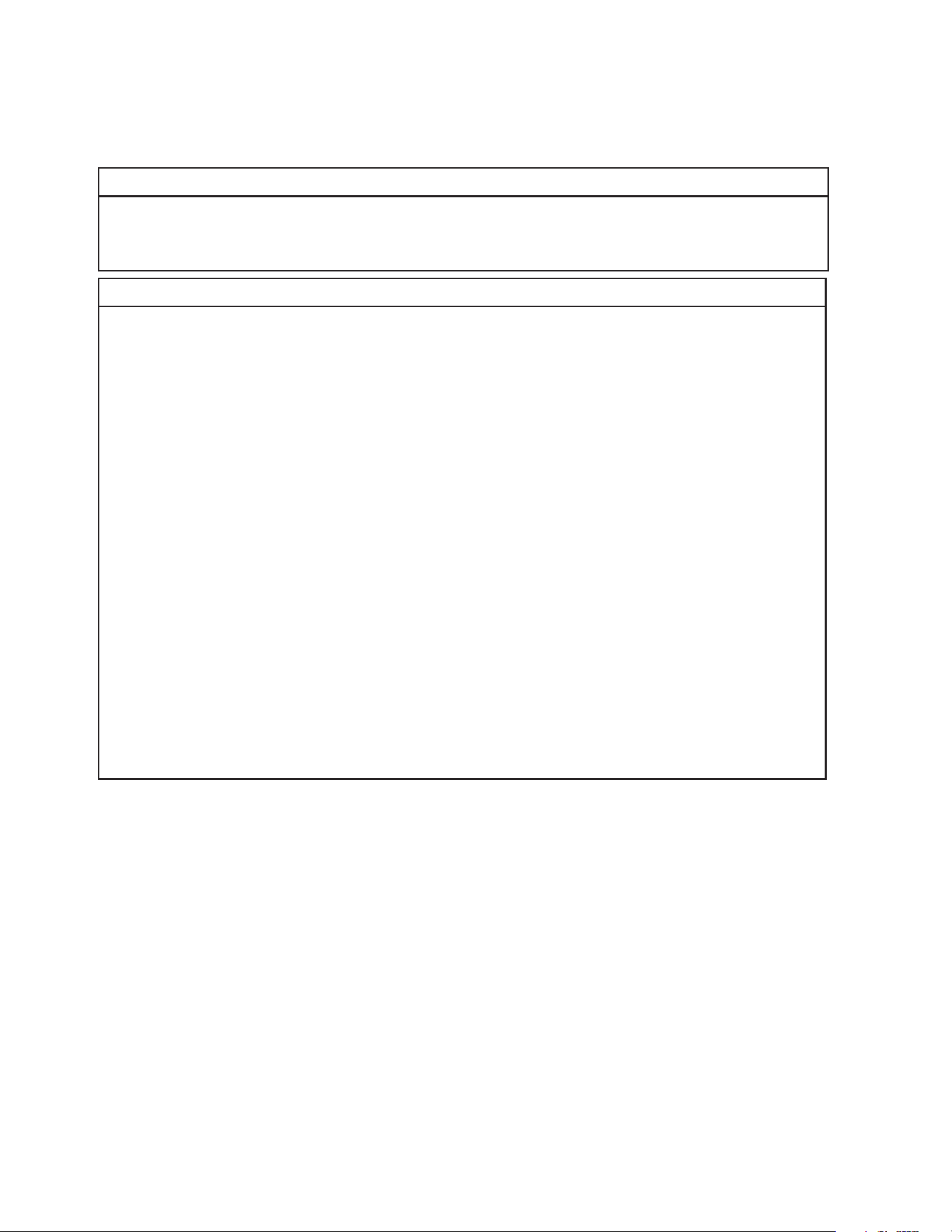
• Electrical connection must be made in accordance with the instructions on the
"WARNING" tag, provided with the pig tail leads in the junction box of the
ice dispenser. See Fig. 5.
• Usually an electrical permit and services of a licensed electrician are required.
• The maximum allowable voltage variation is ±6% of the nameplate rating.
• The white lead must be connected to the neutral conductor of the power source.
• The opening for the power supply connection is 7/8" DIA to t a 1/2" trade size conduit.
DB-130H, DBW-130H
DB-200H, DBW-200H
4A8134-010
115-120/60/1
WARNING
ELECTRICAL CONNECTION
THIS APPLIANCE MUST BE
GROUNDED
Failure to properly ground or wire
this appliance could result in death,
serious injury, or severe damage
to the appliance. The white lead
must be connected to the neutral
conductor of the power source.
See diagram below.
JUNCTION BOX
1
15-120V
BROWN
WHITE
L
N
Fig. 5
16
F. Water Supply and Drain Connections
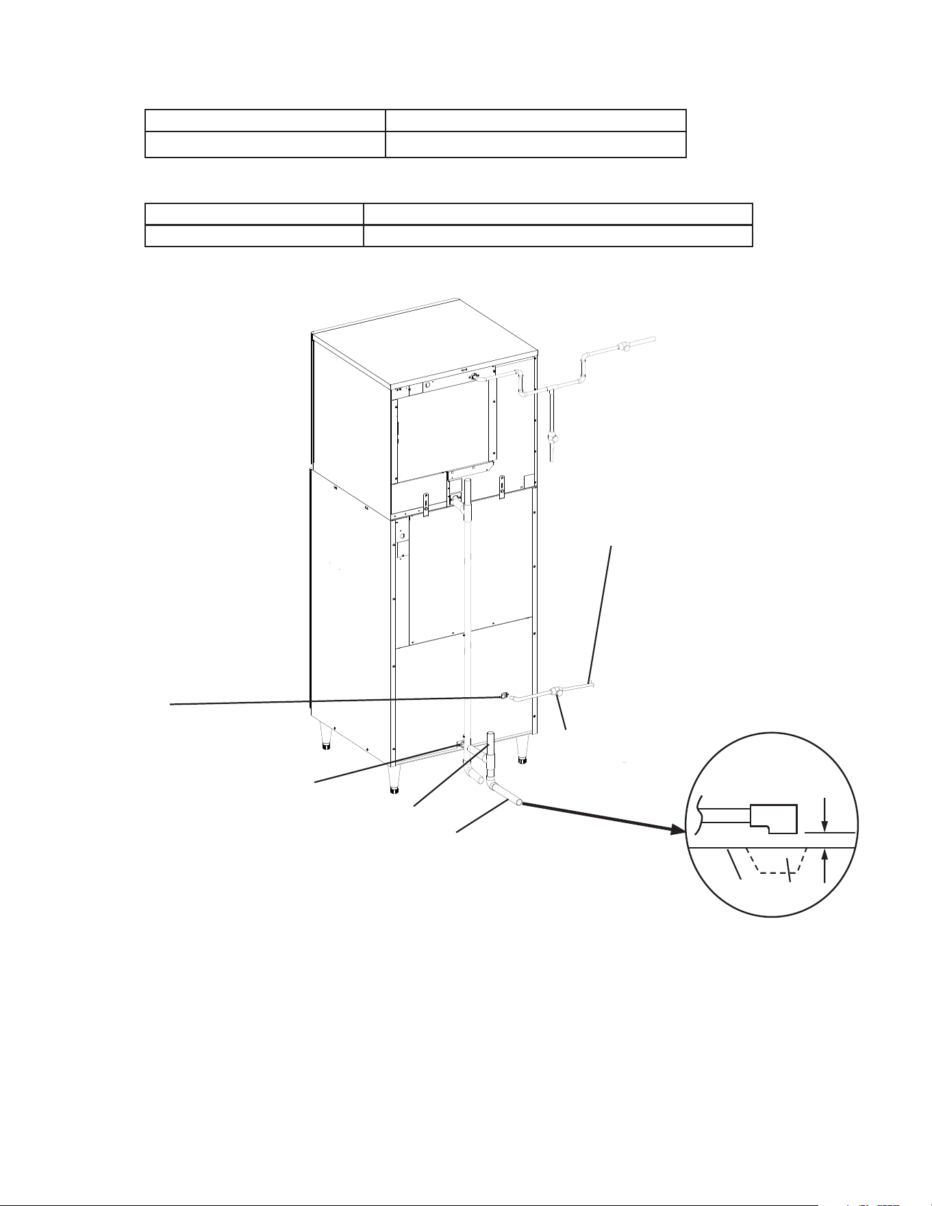
See Fig. 6
Inlet water supply instructions apply to the DBW models only.
WARNING
• Water supply and drain connections must be installed in accordance with applicable
national, state, and local regulations.
• Connect to potable water supply only. Do not connect to a hot-water supply.
NOTICE
• Normal operating water temperature must be within 45°F to 90°F (7°C to 32°C).
Operation of the appliance, for extended periods, outside of this normal temperature
range may affect appliance performance.
• Water supply pressure must be a minimum of 10 PSIG (68.9 kPaG) and a maximum
of 113 PSIG (779.1 kPaG). If the pressure exceeds 113 PSIG (779.1 kPaG), the use
of a pressure reducing valve is required.
• External lters, strainers, or softeners may be required depending on water quality.
Contact your local Hoshizaki Certied Service Representative or local Hoshizaki
distributor for recommendations.
• In areas where water damage is a concern, install in a contained area with a oor
drain.
• Water line installation to the appliance is not warranted by Hoshizaki.
• Be sure there is sufficient extra water supply line and drain line for the appliance to
be pulled out for service.
• Water-hammer issues must be resolved by a qualied plumber before installing the
appliance. Water hammer can cause appliance damage that may lead to water
leakage or ooding
• A minimum of 3/4" nominal ID hard pipe or equivalent is required for the drain line.
Installing a smaller diameter drain line will reduce water ow and may lead to water
leakage or ooding.
• A plumbing permit and services of a licensed plumber may be required in some areas.
• The ice dispenser drain line, icemaker drain line, and water-cooled condenser drain line
(if applicable) must be run separately.
• Drain lines must have 1/4" fall per foot (2 cm per 1 m) on horizontal runs to provide a
proper drain ow. A vented tee connection is also required for proper ow.
• Drain lines should not be piped directly to the sewer system. An air gap of a minimum
of 2 vertical inches (5 cm) must be between the end of the drain pipes from the ice
dispenser, icemaker, and water-cooled condenser (if applicable) and the oor drain.
17
1. All Models: Drain Line Connection
Ice Dispenser Drain Outlet Minimum Ice Dispenser Drain Line Size
3/4" Female Pipe Thread (FPT) 3/4" Nominal ID Hard Pipe or Equivalent
2. DBW Models: Water Dispense Valve Connection
Water Dispense Supply Inlet Minimum Water Dispense Supply Line Size
1/2" Female Pipe Thread (FPT) 1/4" Nominal ID Copper Water Tubing or Equivalent
• A water supply line shut-off valve must be installed.
Minimum 3/4" Nominal ID
Hard Pipe or Equivalent
Separate piping to approved
drain. Leave a 2" (5 cm)
vertical air gap between the
end of each pipe and the
drain.
Be sure there is sufficient
extra water supply line and
drain line for the appliance
to be pulled out for service.
Icemaker
Fig. 6
Models shown: DBW-200H with KMD-705MAJ Icemaker
Ice
Dispenser
Floor
Drain
2" (5 cm) air gap
Dispenser Water
Supply Inlet
1/2" FPT
Note: Shutoff Valve
Should be Installed
Shut-Off Valve
Drain Outlet
3/4" FPT
Vent Tube
Minimum 1/4" Nominal ID Copper
Water Tubing or Equivalent
18
3. DBW Models: Water Dispense Valve Water Pressure Adjustment
After water supply installation, check the water dispense valve for proper operation
and correct water ow pressure. Water pressure coming from the water dispense valve
may be adjusted if necessary. If necessary, follow the steps below to adjust the water
dispense valve water pressure. NOTICE! Setting the water dispense valve pressure
too high may cause water splashing.
1) Remove the front panel.
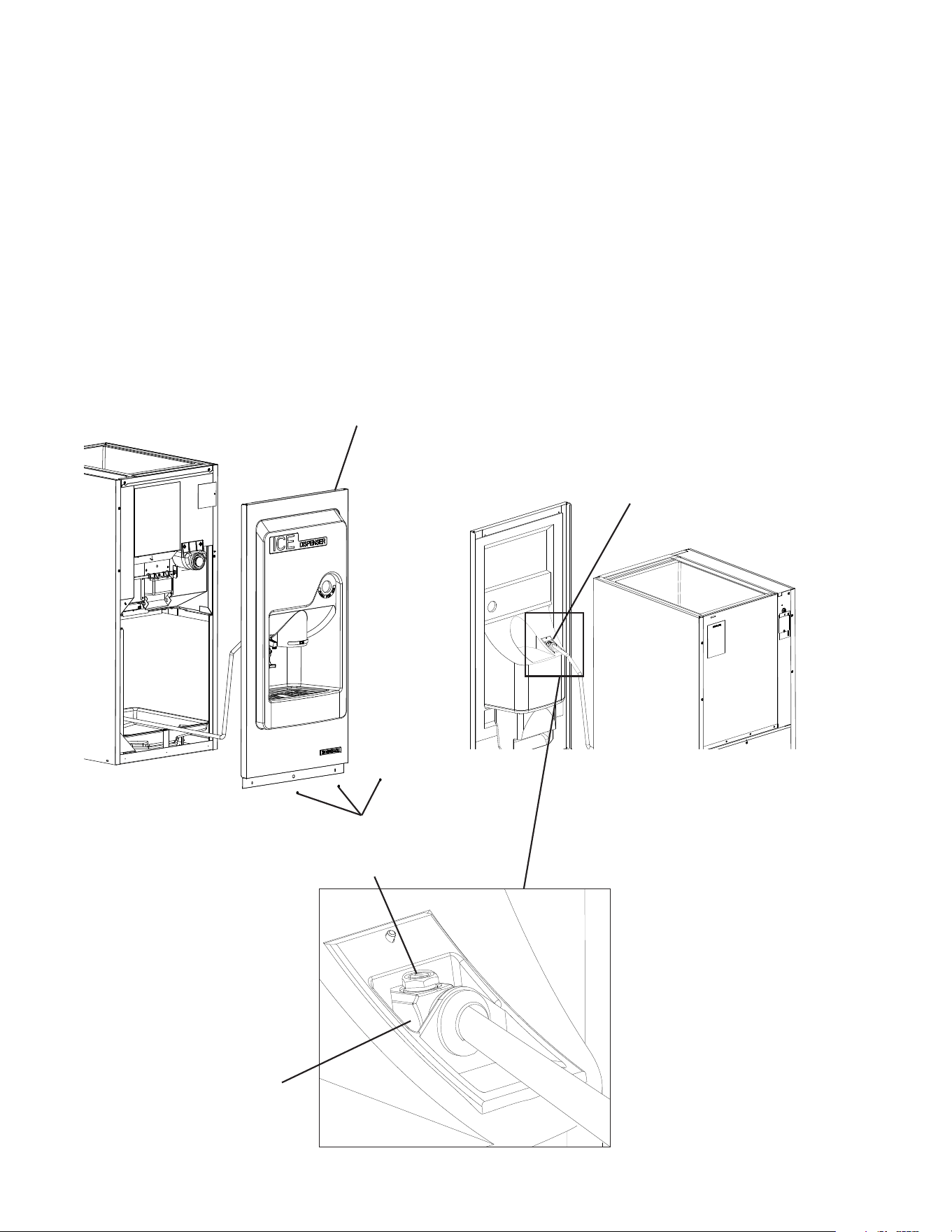
2) Locate the water dispense valve water pressure adjustment screw on the top of the
water dispense valve. See Fig. 7.
3) Turn the water pressure adjustment screw clockwise for higher water pressure or
counter clockwise for lower water pressure.
4) Once the desired pressure is set, replace the front panel in its correct position.
Front Panel
Water Dispense Valve
Water Dispense Valve
Water Pressure Adjustment Screw
Fig. 7
Model Shown: DBW-130H
Screws
19
G. Final Checklist
WARNING
CHOKING HAZARD: Ensure that all components, fasteners, and thumbscrews
are securely in place after installation. Verify that nothing has fallen into the ice
dispenser bin.
1) Is the appliance level?
2) Is the appliance in a site where the ambient temperature is within 45°F to 100°F
(7°C to 38°C) and the water temperature within 45°F to 90°F (7°C to 32°C) all year
around?
3) Is there at least 6" (15 cm) clearance at rear and sides of the appliance?
4) Have the shipping carton, tape, and packing material been removed from the
appliance?
5) Has the protective plastic lm been removed from the panels?
6) Have all electrical and water connections been made? Do electrical and water
connections meet applicable national, state, and local code and regulation
requirements?
7) Has the power supply voltage been checked or tested against the nameplate rating?
Has a proper ground been installed to the appliance?
8) Are the water supply and drain lines sized as specied? Is the water supply line shut-off
valve installed? Has the water supply pressure been checked to ensure a minimum of
10 PSIG (68.9 kPaG) and a maximum of 113 PSIG (779.1 kPaG)?
9) Make sure there are no water leaks.
10) Has the water dispense valve pressure been checked and adjusted if necessary?
11) Is the drain line sized as specied?
12) Has the appliance been cleaned and wiped with a clean cloth?
13) Are all components, fasteners, and thumbscrews securely in place?
14) Has the end user been given the instruction manual, and instructed on how to operate
the appliance and the importance of the recommended periodic maintenance?
15) Has the end user been given the contact information of an authorized service agent?
16) Has the warranty registration been completed and submitted to the factory?
20
III. Operating Instructions
A. Startup
WARNING
• All parts are factory-adjusted. Improper adjustments will adversely affect safety,
performance, component life, and warranty coverage.
• Be sure to follow all Important Safety Information located at the beginning of this
manual.
• Failure to install, operate, and maintain the appliance in accordance with this
manual will adversely affect safety, performance, component life, and warranty
coverage and may result is costly water damage.
1) After installing the appliance per the instructions provided, see the startup instructions
in the icemaker instruction manual. Allow at least three batches of ice production to ll
the ice dispenser bin.
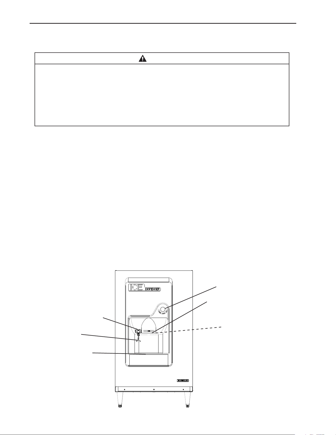
2) Place a container under the ice dispenser spout, then press the ice dispense button.
See Fig. 8. Conrm that ice is dispensing properly.
3) Test the safety switch as follows: While pressing and holding the ice dispense button,
pull the spout towards you. Conrm that the ice dispenser stops.
4) DBW Models:
a) Open the water supply shutoff valve. Place a container under the water dispense
spout and push in the water dispense actuator arm.
b) Conrm that water dispenses properly from water dispense valve and there are no
water leaks.
c) DBW Models: Water ow from water dispenser may be adjusted by turning the screw
at the top of the water valve. See "II.F.3. DBW Models: Water Dispense Valve Water
Pressure Adjustment."
Fig. 8
Ice Dispense Spout
Safety Switch
Ice Station
Ice Dispense Button
Model shown: DBW-200H
DBW Models:
Water Dispense Spout
Water Dispense
Actuator Arm
21
IV. Maintenance
The appliance must be maintained in accordance with the instruction manual and labels
provided. Consult with your local Hoshizaki Certied Service Representative about
maintenance service. To obtain the name and phone number of your local Hoshizaki
Certied Service Representative, visit www.hoshizakiamerica.com.
WARNING
• Only qualied service technicians should service the appliance.
• Failure to install, operate, and maintain the appliance in accordance with this
manual will adversely affect safety, performance, component life, and warranty
coverage.
• Before Servicing: Move the icemaker power switch to the “OFF" position. Turn
off the icemaker and ice dispenser power supplies. Lockout/Tagout to prevent the
power supply from being turned back on inadvertently.
• CHOKING HAZARD: Ensure that all components, fasteners, and thumbscrews are
securely in place after any maintenance is done to the appliance. Make sure that
none have fallen into the ice dispenser.
NOTICE!
• The ice dispenser must be cleaned and sanitized at least once a year. See "IV.B.
Cleaning and Sanitizing Instructions” below. More frequent cleaning, however, may
be required in some existing water conditions.
• To prevent injury to individuals and damage to the appliance, do not use ammonia
type cleaners.
• Carefully follow any instructions provided with the bottles of cleaning and sanitizing
solution.
• Always wear liquid-proof gloves and goggles to prevent the cleaning and sanitizing
solutions from coming into contact with skin or eyes.
22
A. Maintenance Schedule
The maintenance schedule below is a guideline. More frequent maintenance may be
required depending on water quality, the appliance's environment, and local sanitation
regulations.
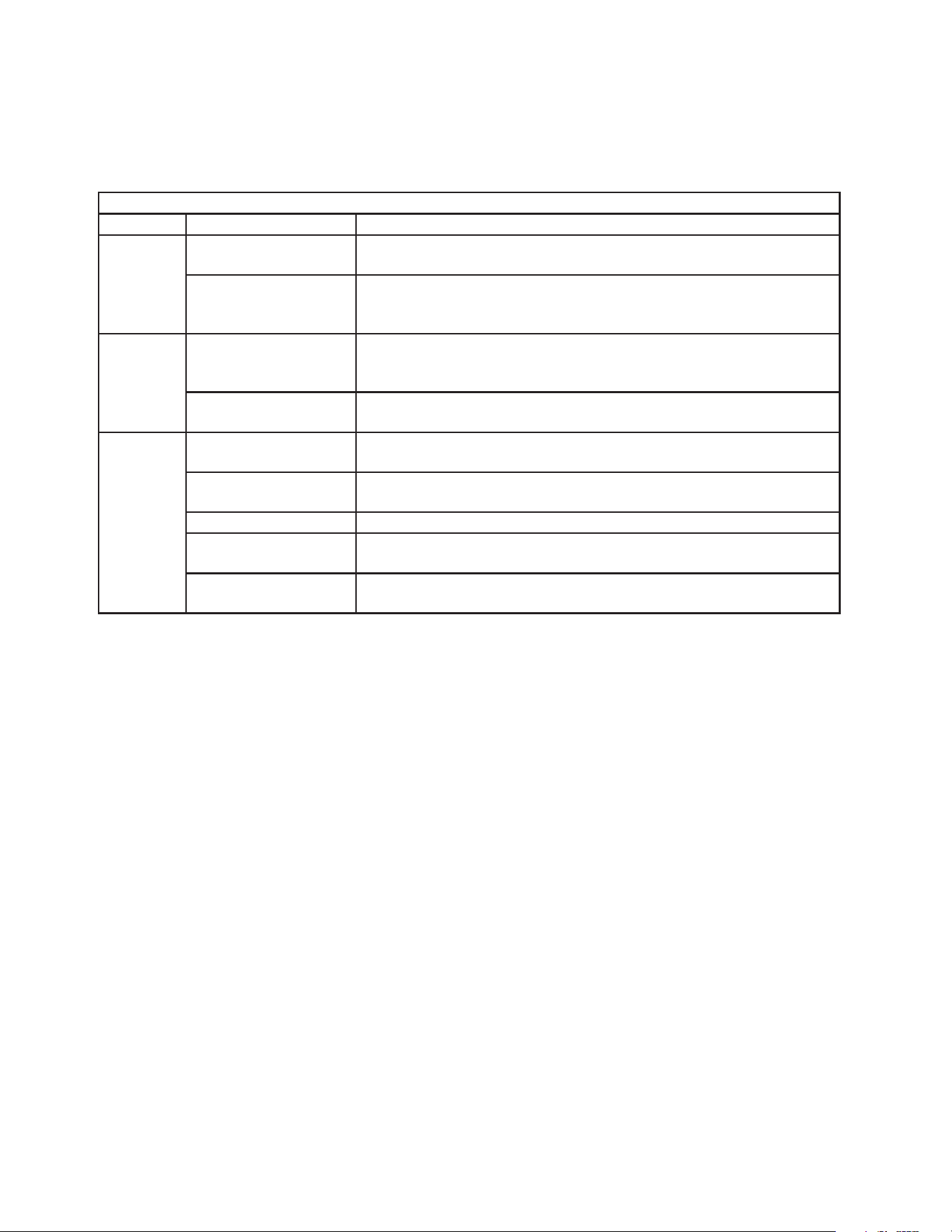
Maintenance Schedule
Frequency Area Task
Monthly External Water Filters
(if applicable)
Check for proper pressure and change if necessary.
Ice Dispenser Exterior Wipe down with a clean, soft cloth. Use a damp cloth containing
a neutral cleaner to wipe off oil or dirt build up. Clean any chlorine
staining (rust colored spots) using a non-abrasive cleanser.
Every 6
Months
Drain Pan Wipe down with a clean cloth and warm water. Slowly pour one cup
of sanitizing solution into the drain pan. Be careful not to overow the
pan. Repeat with a cup of clean water to rinse.
Ice Dispenser Storage
Bin and Drain Line
Check to make sure it is clear.
Yearly Ice Dispenser
Storage Bin
Clean and sanitize at least once a year. More frequent cleaning and
sanitizing may be required in some water conditions.
Ice Dispenser
Water Valve
Close the water dispense valve water supply line shut-off valve and
drain the water hose. Clean the inlet water valve screen.
Water Hoses Inspect the water hoses and clean/replace if necessary.
Icemaker (on top of
dispenser)
Inspect for oil spots, loose components, fasteners, and wires.
Mechanism Assembly Inspect and oil the chain (2 or 3 drops) annually. Adjust as necessary
for 3/8" (10 mm) to 1/2" (13 mm) free play.
23
B. Cleaning and Sanitizing Instructions
The ice dispenser must be cleaned and sanitized at least once a year. More frequent
cleaning and sanitizing may be required in some water conditions. For icemaker cleaning
and sanitizing instructions, see the icemaker instruction manual or the maintenance label
on the icemaker.
WARNING
• To prevent injury to individuals and damage to the ice dispenser, do not use
ammonia type cleaners.
• Carefully follow any instructions provided with the bottles of cleaning and sanitizing
solution.
• Always wear liquid-proof gloves and goggles to prevent the cleaning and sanitizing
solutions from coming into contact with skin or eyes.
• Do not leave the ice dispenser unattended when panels are off.
1. Cleaning Procedure
1) Remove the icemaker front panel, then move the icemaker control switch to the "OFF"
position and turn off the icemaker power supply before servicing. Lockout/Tagout to
prevent the power supply from being turned back on inadvertently.
2) Dispense all the ice from the ice dispenser bin. Turn off the ice dispenser power supply
before servicing. Lockout/Tagout to prevent the power supply from being turned back on
inadvertently.
3) Clean and sanitize the icemaker. Reference the "Cleaning and Sanitizing" procedure
in the icemaker instruction manual or the maintenance label on the icemaker. When
nished, leave the power supply to the icemaker off until completing the ice dispenser
cleaning and sanitizing procedures.
4) Remove or reposition the icemaker to access the inside of the ice dispenser bin.
Be sure that the icemaker is secured and cannot fall.
5) DB models: Remove the ice dispenser front panel and set aside.
DBW models: Turn off the water dispense valve water supply, then remove the front
panel. NOTICE! Do not damage the water valve or water supply hose.
6) Dilute 5 oz. (150 ml) of Hoshizaki "Scale Away" with 1.0 gal. (3.8 l) of warm water.
This is a minimum amount. Make more solution if necessary. IMPORTANT! For safety
and maximum effectiveness, use the solution immediately after dilution.
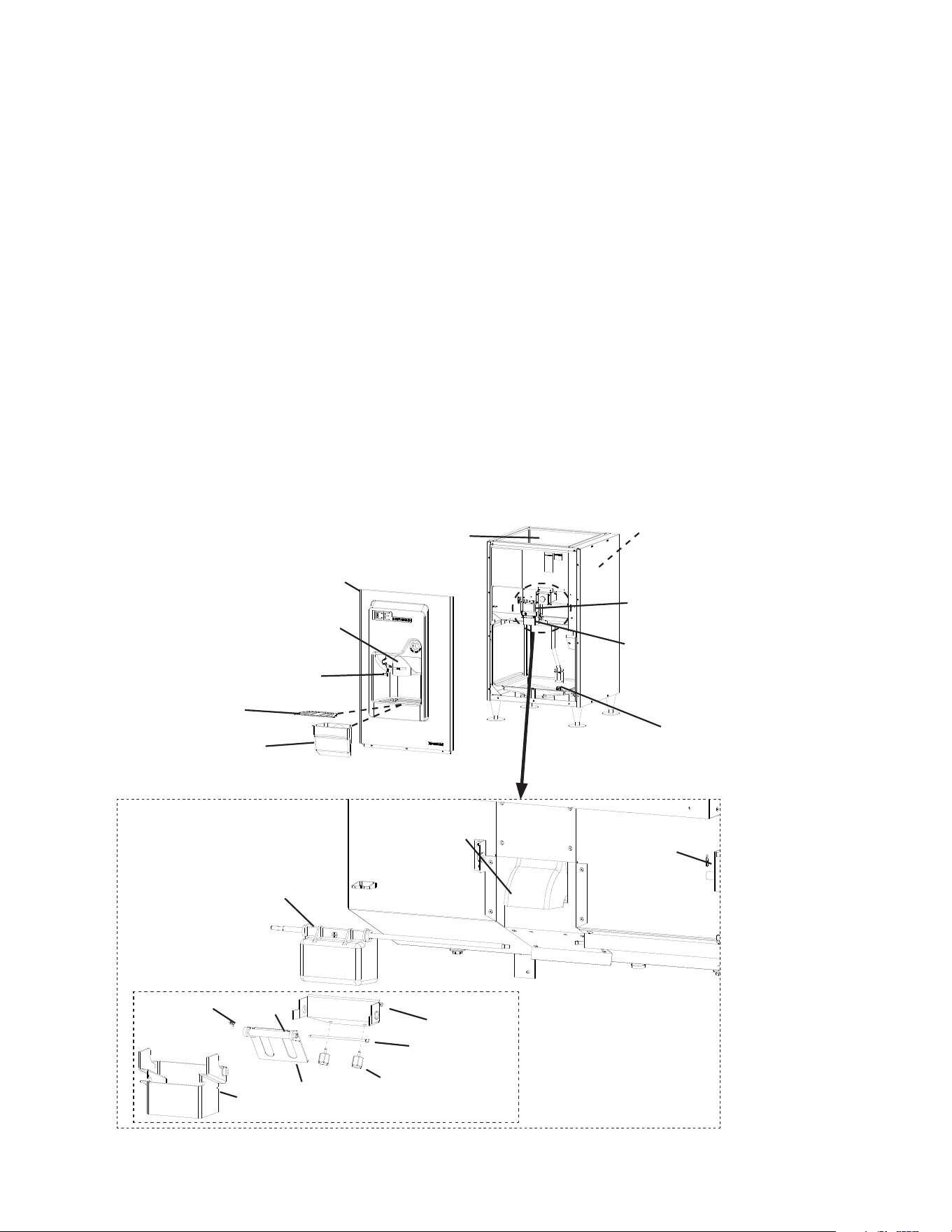
7) Lift and remove the drain gate. Next, remove and clean the chute. See Fig. 9.
8) Using a nylon scouring pad, brushes, and the cleaning solution made in step 6, scrub
the agitator, bin spout, inside of the ice dispenser bin, front panel spout, drain grate,
water dispense valve, and chute. Rinse all parts thoroughly with clean water.
9) Remove the shutter assembly snap pin, then slide the shutter assembly to the right on
DB/DBW-130H or to the left on DB/DBW-200H, and remove.
10) Pull out on the sides of the hook and remove the spout A assembly.
11) Remove the snap pin from shutter B, then remove the shutter shaft, shutter B, and
weight from spout A.
24
12) Scrub the components removed in steps 9, 10, and 11 with cleaning solution. In severe
conditions, immerse the components in cleaning solution for 15 min. before scrubbing.
13) Rinse all parts thoroughly with clean water.
14) Wipe out the drain pan with cleaning solution. Continue to step 16.
2. Sanitizing Procedure
15) Dilute 0.34 . oz. (10.10 ml or .68 tbs) of a 7.5% sodium hypochlorite solution (chlorine
bleach) with 1.0gal. (3.8 l) of warm water. This is a minimum amount. Make more
solution if necessary. IMPORTANT! For safety and maximum effectiveness, use the
solution immediately after dilution.
16) Wipe the agitator, bin spout, inside of the bin, front panel spout, drain grate, water
dispense valve, and chute with sanitizing solution.
17) Rinse the parts thoroughly with clean water.
18) Wipe the components removed in steps 9, 10, and 11 of "IV.B.1 Cleaning Procedure."
with sanitizing solution made in step 15. In severe conditions, immerse the components
in sanitizing solution for 15 min. before wiping.
Fig. 9
Model shown: DBW-200H
Agitator
Front Panel Spout
Chute
Snap Pin
Shutter Assembly
Bin Spout
Hook
Drain Grate
Shutter B
Hook Thumbscrew
Spout
Snap Pin
Weight
Model shown: DBW-200H
Ice Storage Bin
Front Panel
Shutter Shaft
Shutter Assembly
Spout Assembly
Spout A Assembly
Water Dispense Valve
Drain Pan

25
19) Wipe out the drain pan with sanitizing solution.
20) Rinse all parts thoroughly with clean water.
21) Replace all ice dispenser components and the ice dispenser front panel in their correct
positions. NOTICE! On DBW models, do not damage the water valve or water
supply hose.
22) Reposition and secure the icemaker.
23) Move the icemaker control switch to the "ICE" position.
24) Turn the power supply on to the ice dispenser/icemaker, and verify proper operation.
25) Check that there are no water leaks and conrm proper operation.
26) Replace and secure all panels in their correct positions.
26
V. Preparing the Appliance for Periods of Non-Use
WARNING
Only qualied service technicians should service this appliance.
NOTICE
• During extended periods of non-use, extended absences, or in sub-freezing
temperatures, follow the instructions below to reduce the risk of costly water
damage.
• Do not store in sub-freezing temperatures.
1) Close the icemaker and ice dispenser's water supply line shut-off valves.
2) Remove the icemaker front panel, then move the control switch to the "OFF" position.
Turn the icemaker power supply off. See the icemaker's instruction manual "Preparing
the Appliance for Periods of Non-Use."
3) Dispense all of the ice from the ice dispenser bin, then turn off the ice dispenser power
supply.
4) Remove the ice dispenser's front panel.
5) Reposition the icemaker to access the inside of the ice dispenser bin. Be sure that the
icemaker is secured and cannot fall.
6) Dry the storage bin using a clean cloth.
7) Reposition and secure the icemaker in its correct position.
8) Disconnect the ice dispenser's water hose from the water valve and drain all water from
the water hose.
9) Reconnect and secure the ice dispenser's water hose.
10) Wipe out the drain pan.
11) Replace and secure the ice dispenser's front panel in its correct position.

27
VI. Disposal
This appliance must be disposed of in accordance with applicable national, state, and
local codes and regulations.
618 Hwy. 74 South, Peachtree City, GA 30269 USA (P) 770.487.2331 (F) 770.487.3360 hoshizakiamerica.com 1A8244-011