Customer Service:
1-800-851-1085 or
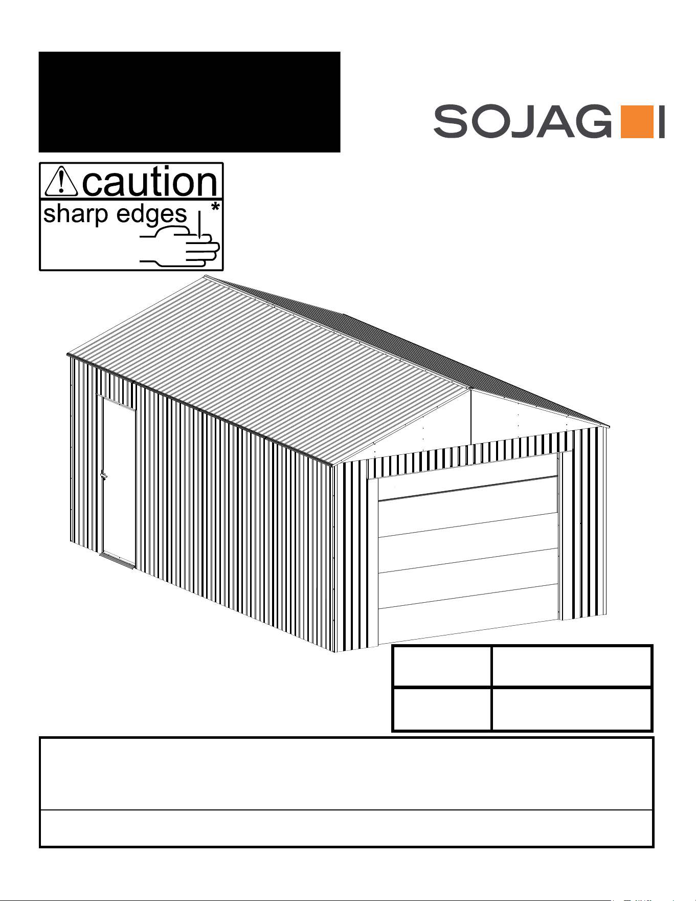
BUILDING DIMENSIONS
Gloves must be worn
at all times to reduce
risk of injury!
Size rounded off to the nearest foot
Owner’s Manual
& Assembly Guide
01GW
729100419
†
Exterior Dimensions
(Roof Edge to Roof Edge)
Width Depth Height
Interior Dimensions
Width Depth Height
Door
Opening
Width Height
Approx.
Size
Storage
Area
†
3,7 m x 3,0 m 10,8 m 29,5 m 371,2cm 313,8 cm 313,6 cm 358,5 cm 300,5 cm 310,5 cm 71,9 cm 199,0 cm
(Roll Up Door)
241,3 cm 212,5 cm
12' x 10' 116 Sq. Ft. 1043 Cu. Ft. 146.13" 123.56" 123.48" 141.13" 118.30" 122.23" 28.30" 78.35"
(Roll Up Door)
95.00” 83.66”
2
3
EVEREST SERIES
12’ GARAGE
Additional
per Extension
142.13” x 60”
361,0 cm x 152,4 cm
Base
Size
142.13” x 119.25”
361,0 cm x 302,9 cm
Each Extension adds an additional 60” (152,4 cm) in length, 59 Sq. Ft. (5,4 m
2
)
additional storage area, and 529 Cu. Ft. (15,0 m
3
) additional storage volume.
* See Inside for Detailed Safety Information.
All Sizes
1DLQWHUQHWHMHNGLVSR]tFLLQiYRGQD]RVWDYHQLHYćDOãtFKMD]\NRFK
1iYRGNPRQWiåLYGDOãtFKMD]\FtFKMHNGLVSR]LFLYRQOLQHYHU]L
3ĜtVWXS]tVNiWHSRQDVNHQRYiQt45NyGXQtåH
$]|VV]HV]HUHOpVL~WPXWDWyWRYiEELQ\HOYHNHQLVHOpUKHWĘRQOLQH
ȊʌȐȡȤİȚįȚĮșȑıȚȝȠıIJȠįȚĮįȓțIJȣȠIJȠİȖȤİȚȡȓįȚȠıȣȞĮȡȝȠȜȩȖȘıȘȢ
ıİʌİȡȚııȩIJİȡİȢȖȜȫııİȢȈĮȡȫıIJİIJȠȞʌĮȡĮțȐIJȦțȫįȚțĮ
45ȖȚĮȞĮĮʌȠțIJȒıİIJİʌȡȩıȕĮıȘ
P/N 6PP722621216
GB: Assembly manual in additional languages available online.
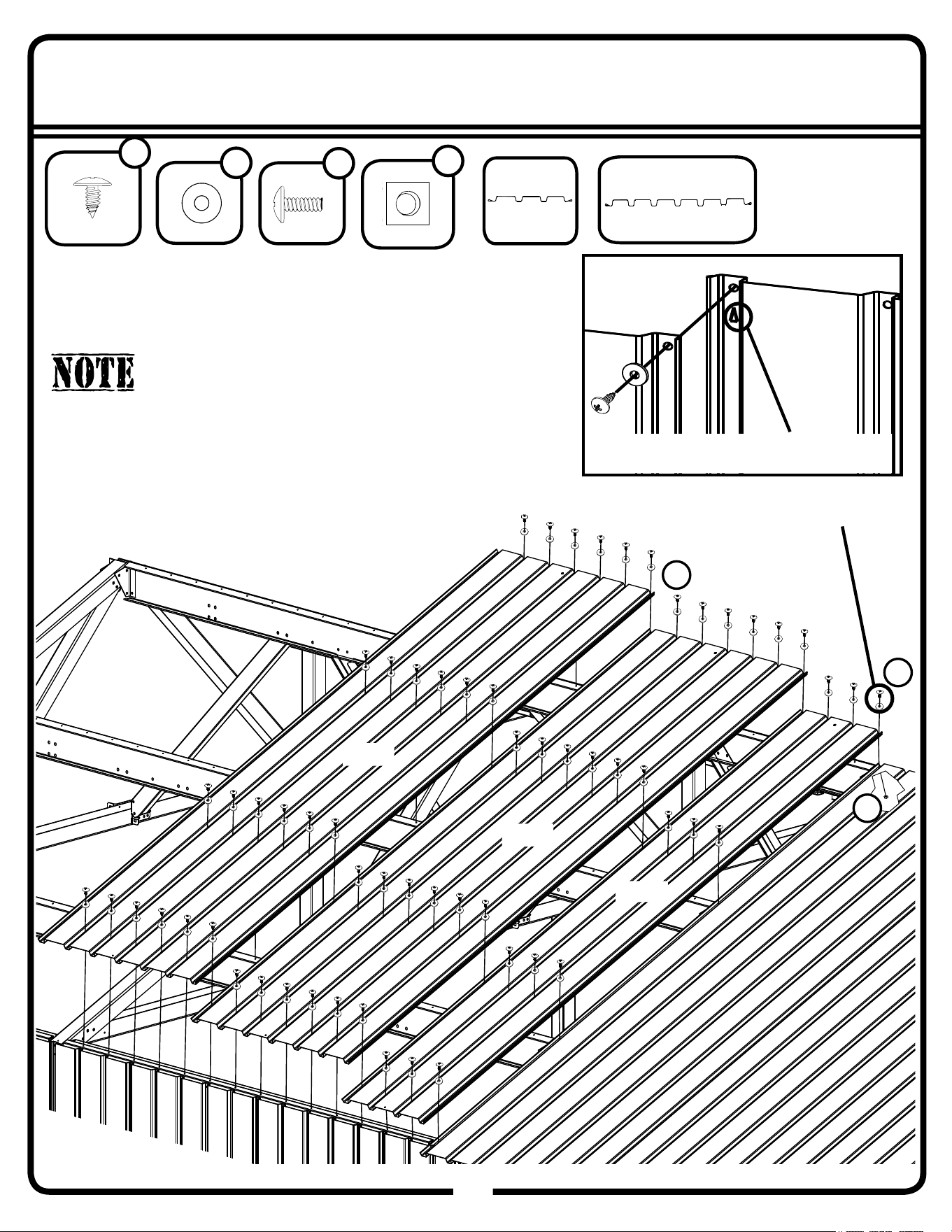
Scan QR code below to access.
FR: Manuel de montage disponible en ligne dans d’autres langues.
Pour y accéder, scannez le code QR ci-dessous.
DE: Montageanleitung in zusätzlichen Sprachen online verfügbar.
Scannen Sie den QR-Code unten, um darauf zuzugreifen.
IT: Manuale dell’assemblea in altre lingue disponibile online.
Per accedere effettua la scansione del codice QR in basso.
DT: Samlingshåndbog i yderligere sprog til rådighed online.
Scan QR kode nedenunder for at få adgang.
SK: Na internete je k dispozícii návod na zostavenie v ďalších jazykoch.
Dostanete sa k nemu naskenovaním kódu QR.
CZ: Návod k montáži v dalších jazycích je k dispozici v online verzi.
Přístup získáte po naskenování QR kódu níže.
DE: Monteringsmanual på ytterligare språk tillgängliga online.
Skanna QR-kod nedan för att komma åt.
RM: Manualul de asamblare în alte limbi disponibile online.
Scanați codul de mai jos pentru a accesa.
3
SAFETY & MAINTENANCE
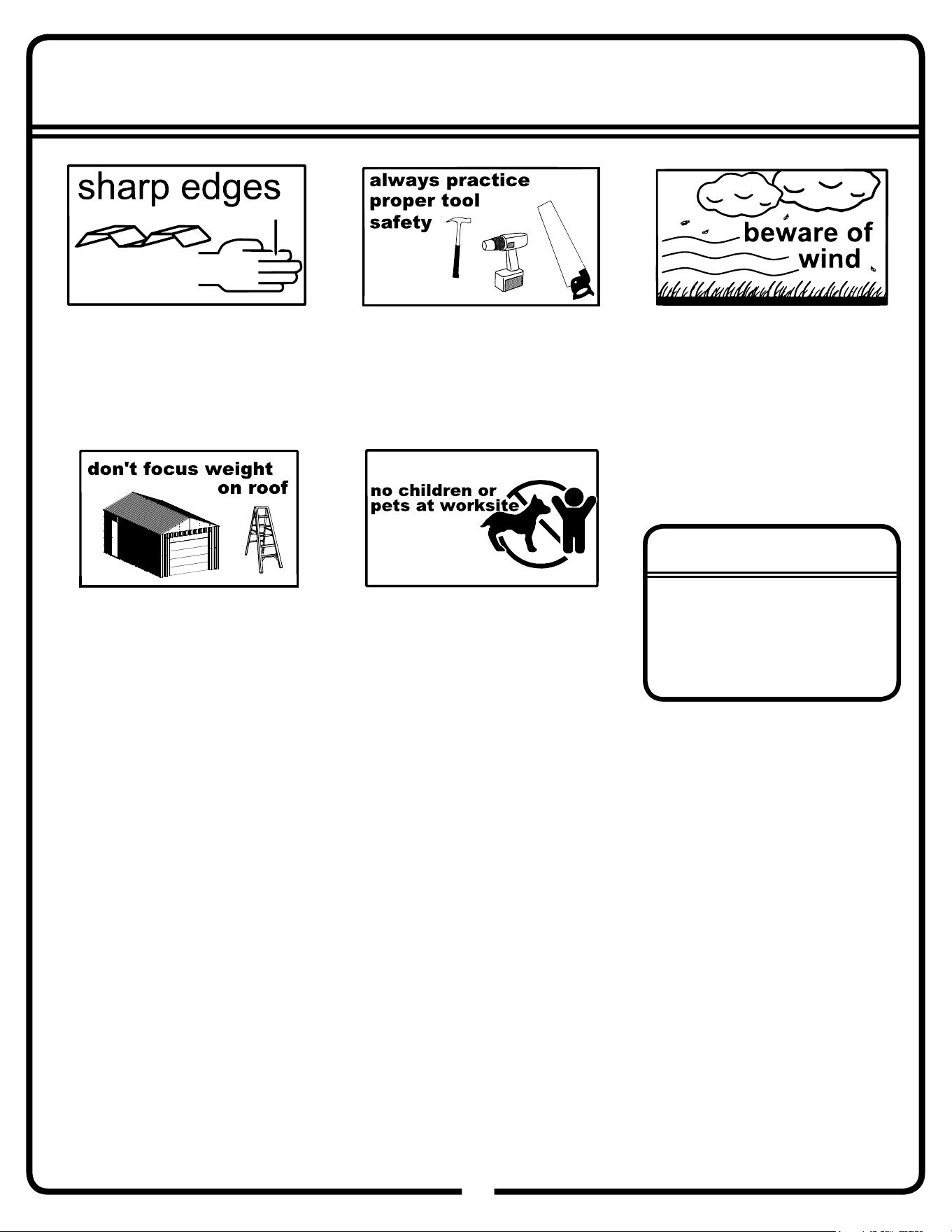
Safety precautions MUST be followed at all times throughout the construction of your building!
Care must be taken when handling
various pieces of your building since
many contain sharp edges. Please
wear work gloves, eye protection and
long sleeves when assembling or
performing any maintenance on your
building.
Practice caution with the tools being
used in the assembly of this building.
Be especially familiar with the
operation of all power tools.
Keep children and pets away from the
worksite during construction and until
the building is completely assembled.
This will help avoid distractions and
any accidents which may occur.
NEVER concentrate your weight on
the roof of the building. When using
a step ladder make sure that it is
fully open and on even ground before
climbing on it.
Do NOT attempt to assemble your
building on a windy day. The large
panels can catch the wind like a “sail”,
causing them to be whipped around
making construction diffi cult and
unsafe.
Do NOT attempt to assemble your
building before double checking that
you have all the parts indicated on the
parts list as well as all hardware. Any
building left partially assembled may be
seriously damaged by even light winds.
IMPORTANT NOTE ON
ANCHORING
• Your building MUST be anchored to
prevent wind damage. See anchoring
page for more info.
• You must also have a temporary
anchoring system in place in case you
need to take a break from assembly.
03GW
Exterior Care:
For a long lasting fi nish, clean the exterior surface. We recommend washing with a mild soap solution. DO NOT use power washing to clean
your shed.
Combustibles and corrosives must be stored in air tight containers designed for chemical and/or combustible storage. Corrosive chemicals
such as fertilizers, pesticides and herbicides should be cleaned off the interior and exterior surfaces immediately. Rust caused by chemical
damage is not covered by the warranty.
Rust protection precautions may help to stop rust from developing, or stop it quickly as soon as it appears.
• Avoid nicking or scraping the coating surface, inside and out.
• Keep roof and base perimeter free of debris and leaves which may accumulate and retain moisture. These can do double damage since
they give off acid as they decay.
• Touch up scrapes or nicks and any area of visible rust as soon as possible. Make sure the surface is free of moisture, oils, dirt or grime and
then apply an even fi lm of high quality touch-up paint.
• Various paint manufacturers provide products for rust treatment and coverage. If surface rust does appear on your shed we recommend
treating those areas as soon as possible, following the paint supplier of your choice instructions.
• Our customer service department can provide the paint tinting formula for matching the color of your shed. We also have touch-up paint
available for repairing small nicks and scratches.
Roof: Keep the roof clear of leaves and snow
. Heavy amounts of snow on the roof can damage the building making it unsafe to enter.
Fasteners: Regularly check fasteners and retighten as necessary.
General: Wash off inked part numbers on coated panels with soap and water.
Please note, Manufacturer cannot be held responsible for any consequences due to buildings that are not installed per these instructions, or
for damage due to weather conditions or acts of God.
Keep these assembly instructions and owner’s manual for future reference.
4
ASSEMBLY TIPS & TOOLS
How to Select and Prepare Your Building Site: Before
you start to assemble your
building, you will want to decide on a good location. The best location is a level area with good drainage.
• Allow enough working space so it is not diffi cult to move parts into position for assembly. Also, there needs to be enough
space outside the building to be able to fasten the panel screws from the outside.
• Before assembling any parts, your base should be constructed and an anchoring system should be ready to use.
Watch the Weather Closely: Be
sure the day you choose to install your building is dry and calm.
Do NOT attempt to assemble your building on a windy day. Be careful on wet or muddy ground.
Use Teamwork: Two or more people are required to assemble your building. One person can hold
the parts or panels in place while the other person fastens them together and handles the tools. This
makes the process of assembling your building faster and safer.
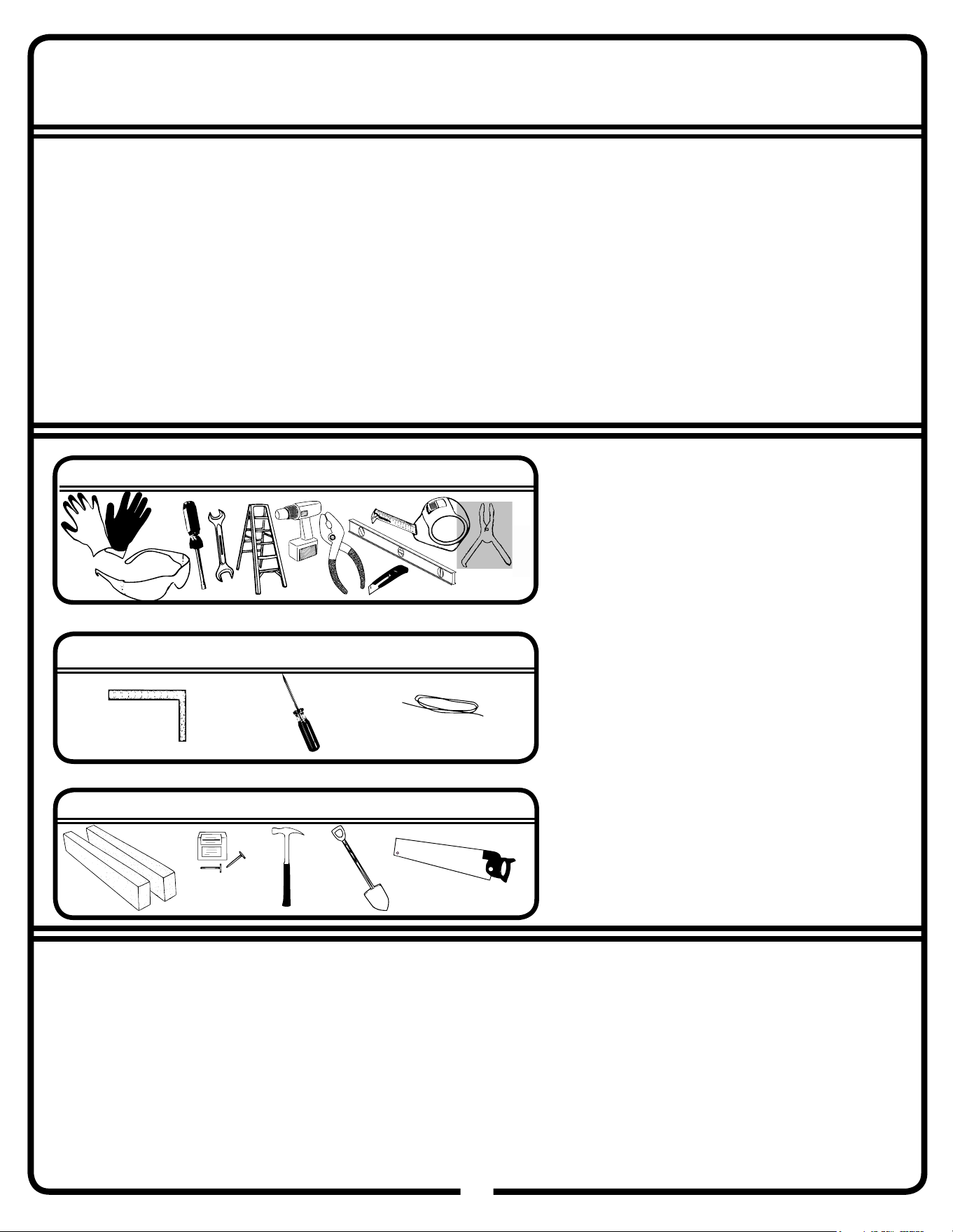
Tools and Materials: Here is a list of some basic tools and materials you will need to assemble
your building. Decide which method of anchoring and the type of base you will use to make a complete
list of the materials you will need.
• Work Gloves
•
Safety Glasses
• Nut Driver or Wrench
• Step Ladder 8’
• Power Drill (Cordless, Variable Speed)
• Pliers
• Utility Knife or Scissors
• Carpenter’s Level
• Tape Measure
• Clamp
• Spray Lubricant
• Square
• String (for squaring the frame)
• Awl (to align holes)
• Lumber and/or Concrete
• Hammer and Nails
• Spade or Shovel
• Hand Saw or Power Saw
RECOMMENDED TIME SAVERS
BASE PREPARATION TOOLS
07BQ
WHAT YOU NEED
3
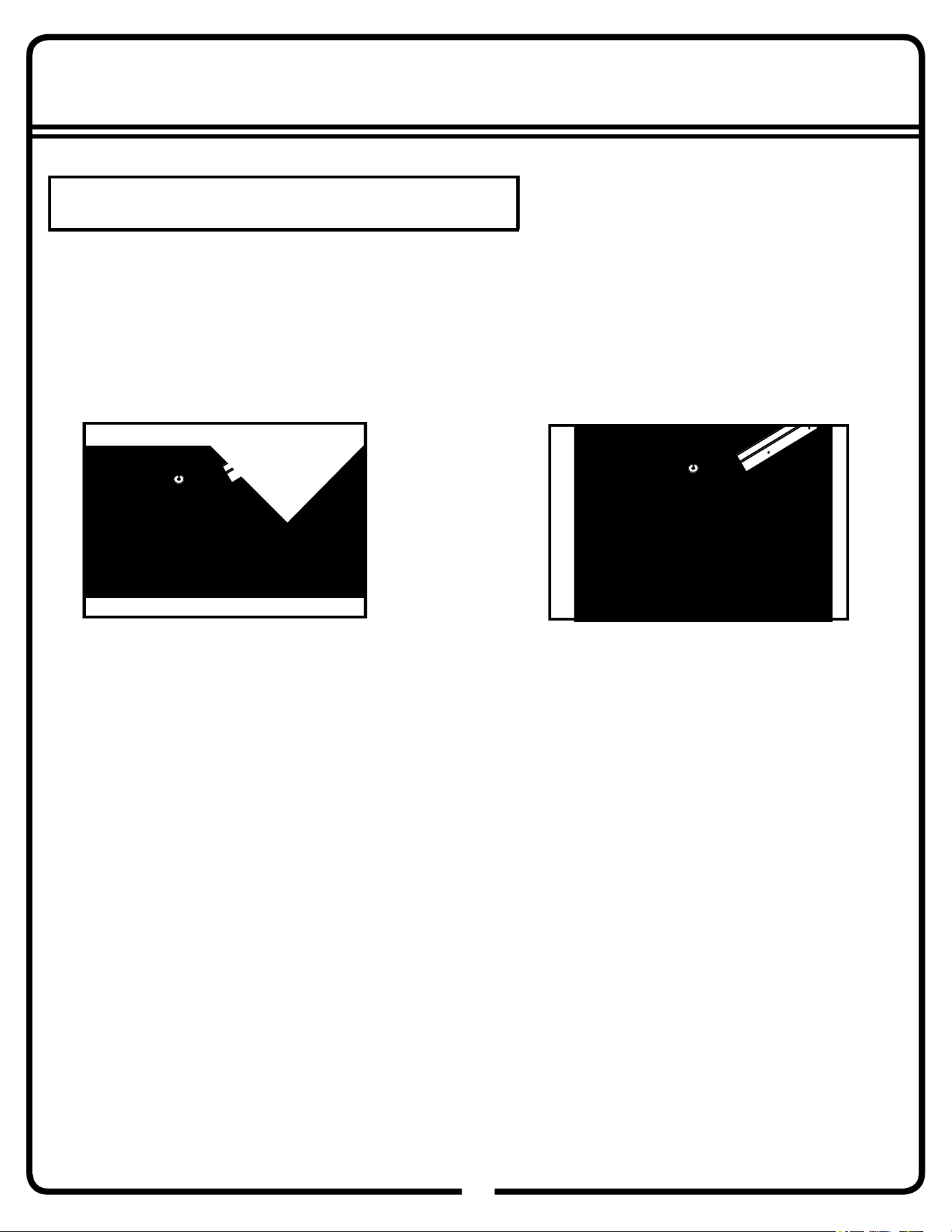
Base
05GW
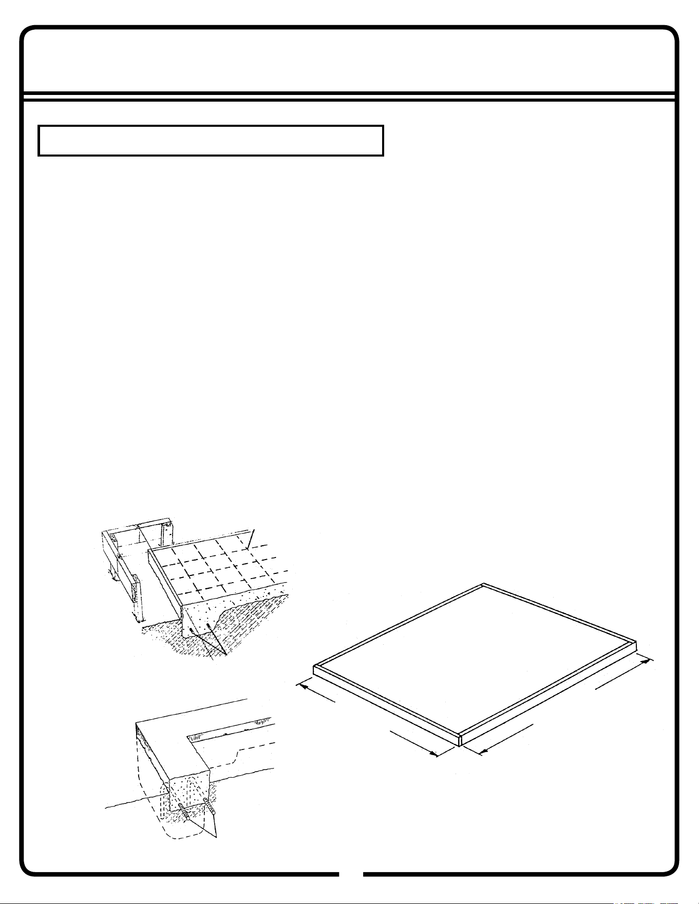
The Base For Your Building
Concrete Slab
The slab should be at least 4" (10,2 cm) thick. It must be level and fl at to provide good support for the frame.
The following are the recommended materials for your base.
2 x 4's (38 mm x 89 mm) (will be removed once the concrete cures)
Concrete Sheet of 6 mil plastic
We recommend for a proper strength concrete to use a mix of:
1 part cement 3 parts pea sized gravel 2 1/2 parts clean sand
Prepare the Site/Construct a Base
1. Dig a square, 6" (15,2 cm) deep into the ground (remove grass).
2. Fill up to 4" (10,2 cm) in the square with gravel and tamp fi rm.
3. Cover gravel with a sheet of 6 mil plastic.
4. Construct a wood frame using four planks of 2x4 (38 mm x 89 mm)
lumber.
5. Pour in concrete to fi ll in the hole and the frame giving a
total of 4" (10,2 cm) thick concrete. Be sure surface is level.
Allow 3 - 5 hours for construction and a week for concrete curing time.
Note: Before beginning construction, check local building codes
regarding footings, location and other requirements.
119.25" 302,9 cm
Add'l 60" 152,4 cm
per extension
Note: Finished Slab dimensions, with lumber removed.
Reinforcing
Rods
Reinforcing
Rods
Optional Footer Type of Foundation
Welded Wire
Fabric
142.13"
361,0 cm
FRONT (ROLL-UP DOOR)
5
3
Anchoring
06GW
6
It is important that the entire fl oor frame be anchored after the building is erected.
Below are recommended ways of anchoring.
Anchoring Down The Building
Anchoring into Concrete:
For poured concrete slab or footing or patio blocks:
Use 1/4" x 2" (6 mm x 51 mm) Lag Screws.
Anchoring into Wood:
Use 1/4" (6 mm) Wood Screws. There are 1/4" (6 mm)
dia. holes provided in the frames for proper anchoring.
17
HARDWARE LIST...
07GW
7
1
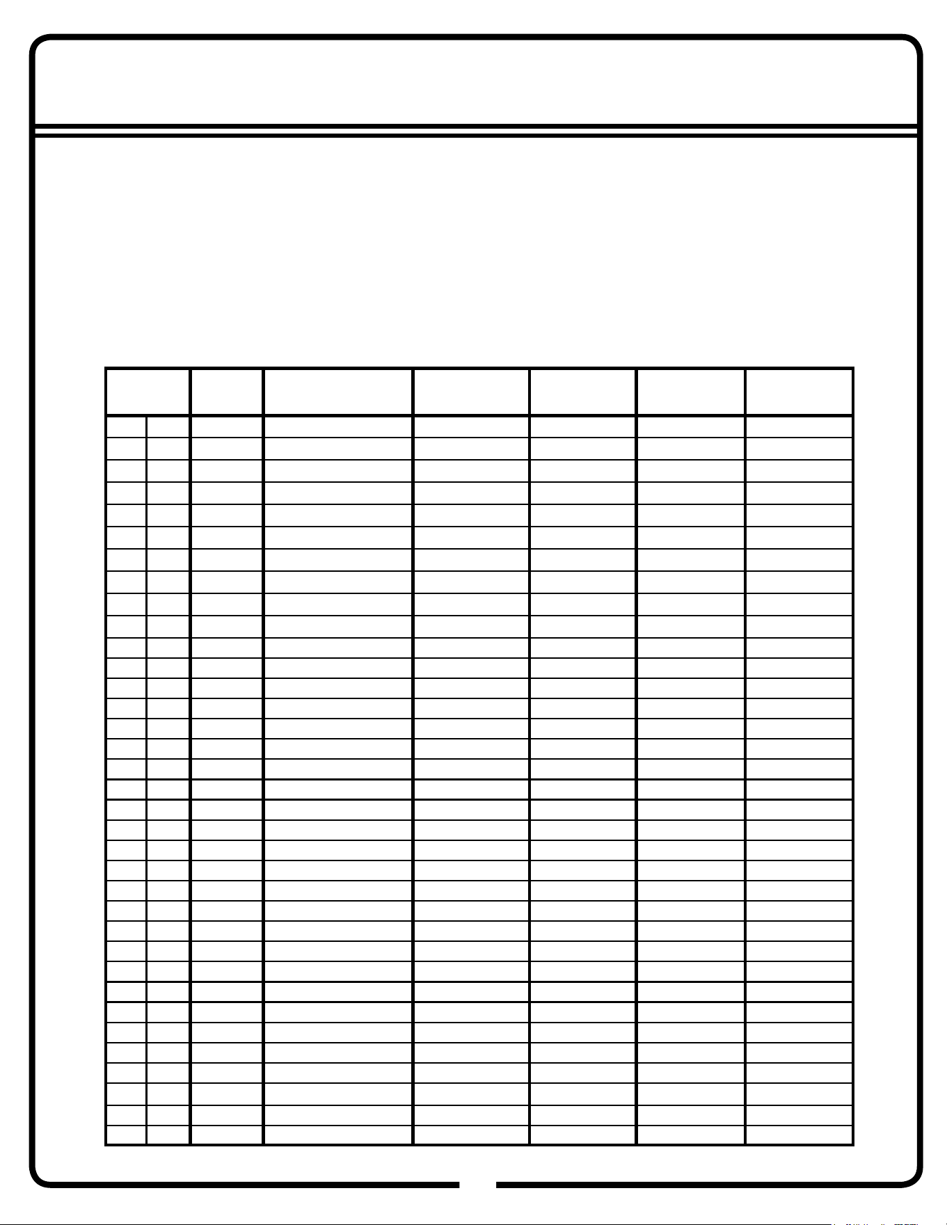
Hardware Views by Key No.
13
19
8, 9, 107
1 65103 Hex Nut (#8-32) 18
2 65101 Square Nut (1/4-20) 10
3 65106 Square Nut (#10-32) 243
4 65943 Bolt (Bare) (#10-32 x 7/16) (10 mm) 143
5 65943 Bolt (Wall Color) (#10-32 x 7/16) (10 mm) 64
6 65943 Bolt (Roof Color) (#10-32 x 7/16) (10 mm) 36
7 66783 Flathead Bolt (#8-32x1/2) 18
8 66611 Tapping Screw (Bare) (#10AB x 1/2) (13 mm) 241
9 66611
Tapping Screw (Wall Color) (#10AB x 1/2) (13 mm) 380
1
0 66611 Tapping Screw (Roof Color) (#10AB x 1/2) (13 mm) 244
11 65989 Hex Head Bolt (#1/4-20x1/2) 10
12 65020 Flat Washer 8
13 66646 Washer Sheet 18
14 6228 Track Support 2
15 60H Corner Cap 4
16 30003 Peak Cap 2
17 30005 VHB Tape 1
18 30018 Alcohol Wipe Packet 2
19 66609 Hinge 3
20 7003 Left Shear Plate 6
21 7004 Right Shear Plate 6
22 7022 Eave Bracket 4
Key
No.
Part
No.
Part
Description
Qty.
List
4, 5, 6
The fasteners used in each step are shown
actual size at the top of each page. If you
are unsure which fastener to use, hold it up
to the picture and use the one that matches.
15
20
7003
3 65106 Square Nut (#10-32) 44
4 65943 Bolt (Bare) (#10-32 x 7/16) (10 mm) 34
6 65943 Bolt (Roof Color) (#10-32 x 7/16) (10 mm) 10
8 66611 Tapping Screw (Bare) (#10AB x 1/2) (13 mm) 140
9 66611 Tapping Screw (Wall Color) (#10AB x 1/2) (13 mm) 90
1
0 66611 Tapping Screw (Roof Color) (#10AB x 1/2) (13 mm) 126
13 66646 Washer Sheet 6
14 6228 Track Support 2
20 7003 Left Shear Plate 6
21 7004 Right Shear Plate 6
22 7022 Eave Bracket 4
Key
No.
Part
No.
Part
Description
Qty.
List
21
7004
Extension 1205M
2
3
11
12
14
16
17
18
22
BB - Bare Bolt
WB - Wall Bolt
RB - Roof Bolt
BS - Bare Screw
WS - Wall Screw
RS - Roof Screw
N - Nut
W - Washer
6
PARTS LIST...
8
08GW
Assembly Part Part Extension
Key No. Number Description C1 C2 C3 1205M
1 6372
Gable Strut
4 2
2 6380
Gable Brace Outer
4
3 6381
Gable Brace Mid
4
4 6382
Gable Brace Center
2
5 7942
Right Gable
2
6 7943
Left Gable
2
7 11149
Ridge Beam
12
8 11150
Right Rear Frame
2
9 11151
Frame, Side Floor
2
10 11152
Channel, Side Wall
2
11 11153
Panel, Wall Corner Narrow
4
12 11154
Ridge Beam
6
13 11155
Floor Side Frame
2
14 11156
Corner Support Structural
8
15 11157
Panel, Wall Full
10 4
16 11158
Frame, Front Floor
3
17 11159
Channel, Side Wall
2
18 11160
Panel, Wall Half
1
19 11161
Header Angle
2
20 11162
Channel, Header
2
21 11163
Channel, Mid Wall
2
22 11165
Channel, Mid Wall
2
23 11166
Panel, Wall Half
3 2
24 11168
Panel, Wall Corner
4
25 11169
Panel, Wall Half
1
26 11170
Panel, Wall Full
1
27 11171
Panel, Jamb Left
1
28 11172
Panel, Wall Full
4
29 11173
Panel, Wall Half
1
30 11174
Panel, Roof Full
8 4
31 11175
Panel, Roof Half
2
32 11176
Channel, Side Door
1
33 11177
Door Stop
2
34 11178
Panel, Roof Corner Right
2
35 11179
Column, Front
2
Confi rm that all hardware and parts are present before attempting to assemble
your Storage Unit.
Customer Service:
1-800-851-1085 or [email protected]
For missing or damaged parts contact Customer Service. Do not return to store.
6
PARTS LIST...
9
09GW
Assembly Part Part Extension
Key No. Number Description C1 C2 C3 1205M
36 11180
Frame, Rear Right
1
37 11181
Header Angle Side
1
38 11182
Panel, Jamb Right
1
39 11183
Track Strut
2
40 11184
Frame, Side
1
41 11185
Panel, Jamb Right
1
42 11186
Truss, Column
3 2
43 11187
Chord, Truss Upper
2 2
44 11188
Chord, Truss Lower
2 2
45 11189
Chord, Truss Lower
1 1
46 11190
Chord, Truss Vertical
2 2
47 11191
Chord, Truss Upper
2 2
48 11192
Chord, Truss Diagonal
2 2
49 11193
Panel, Door
1
50 11195
Door Brace, Vertical
2
51 11196
Channel, Door Horizontal
2
52 11197
Support, Door Track
4
53 11200
Panel, Door Back
1
54 11201
Lintel
1
55 11202
Ridge Cap Outside
2
56 11203
Trim, Side Roof Inside
2
57 11204
Trim, Side Roof Outside
4
58 11205
Ridge Cap Inside
1
59 11207
Panel, Wall Half
1
60 11290
Support, Right Track
1
61 11291
Lintel
1
62 11292
Ramp
1
63 30002
Handle, Side Door Assembly
1
64 80141
Frame, Side Floor Left
2
65 80143
Channel, Side Wall Left
2
66 80145
Frame, Front Floor Left
3
67 80147
Channel, Mid Wall Left
1
68 80149
Frame, Rear Left
1
69 80151
Panel, Roof Corner Left
2
70 80153
Panel, Jamb Left
1
71 80159
Left Rear Frame
2
72 80161
Panel, Wall Half
1
73 80191
Support, Left Track
1
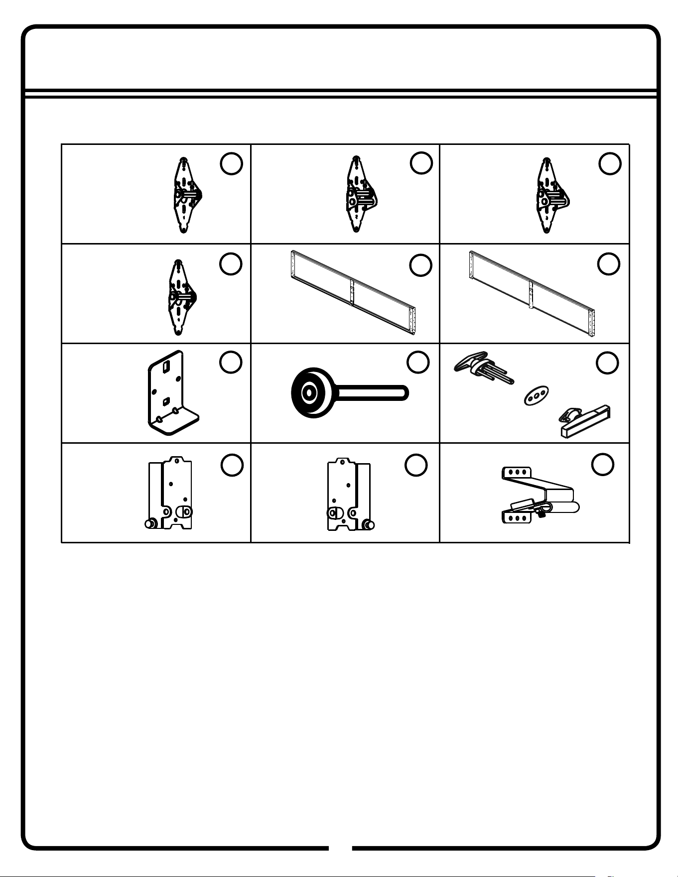
17
Components for Garage Door (GD)
10GW
10
Door Section with
weather stripping
#1 End Hinge
#3 End Hinge
#2 End Hinge
#1 Center Hinge
Door Lock
Assembly
T
op
Fixture
Bottom
Fixture Right
Bottom
Fixture Left
Roller
Inside Step
Plate
Door Section
2
2
2
3
1
3
1
1
1 1
2
10
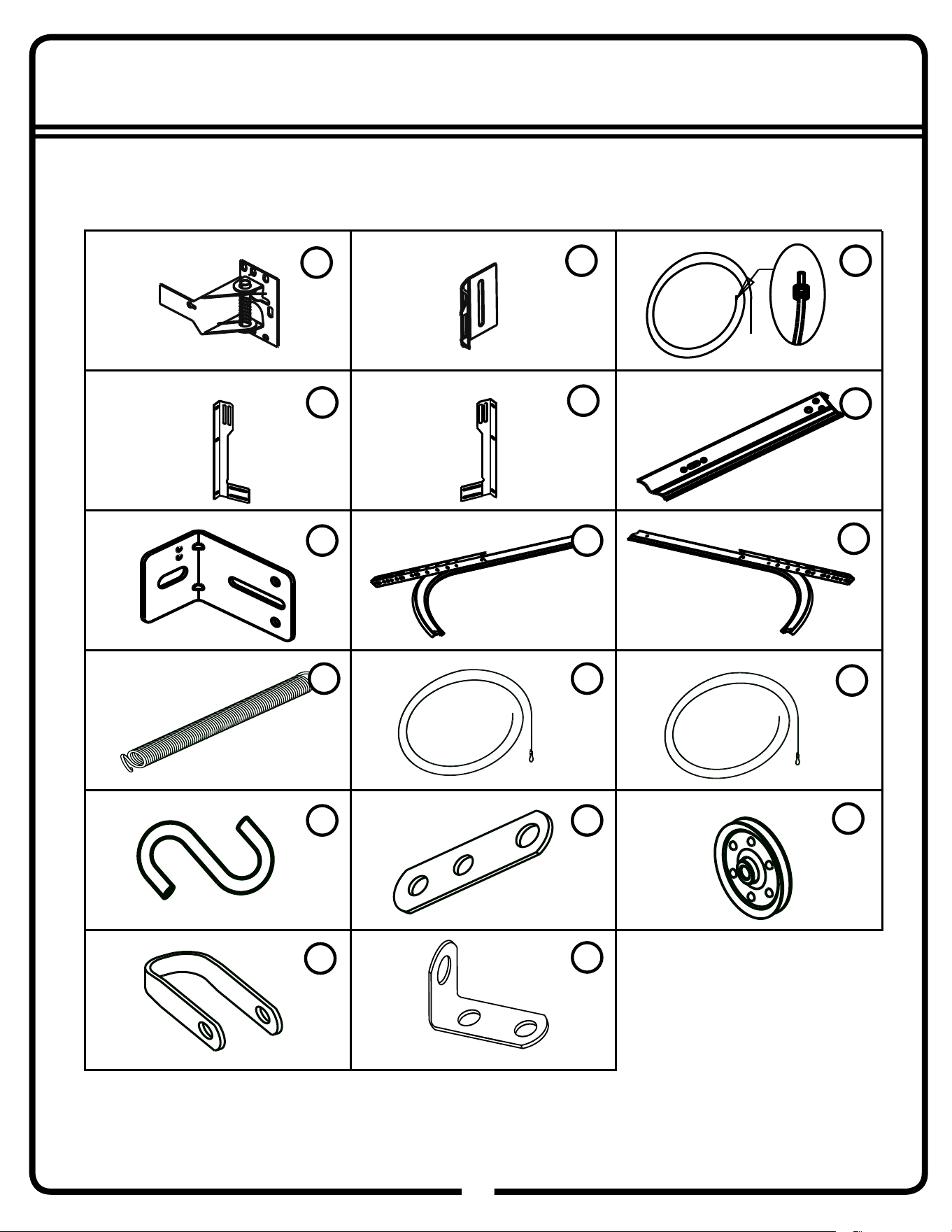
17
Components for Garage Door (GD)
11GW
11
Snap Latch
Keeper
Cable
Vertical Track
Flag Angle
Left
Flag Angle
Right
Snap Latch
Horizontal Curve
Track Right
Horizontal Curve
Track Left
Spring
Cable
Safety
Cable
S Hook
Cable Clip Pulley
Clevis
Track Bracket
2
2 1
1
1
2
4 1
1
2 2
2
2 2
4
2
Extension Spring
Cable Clip
2
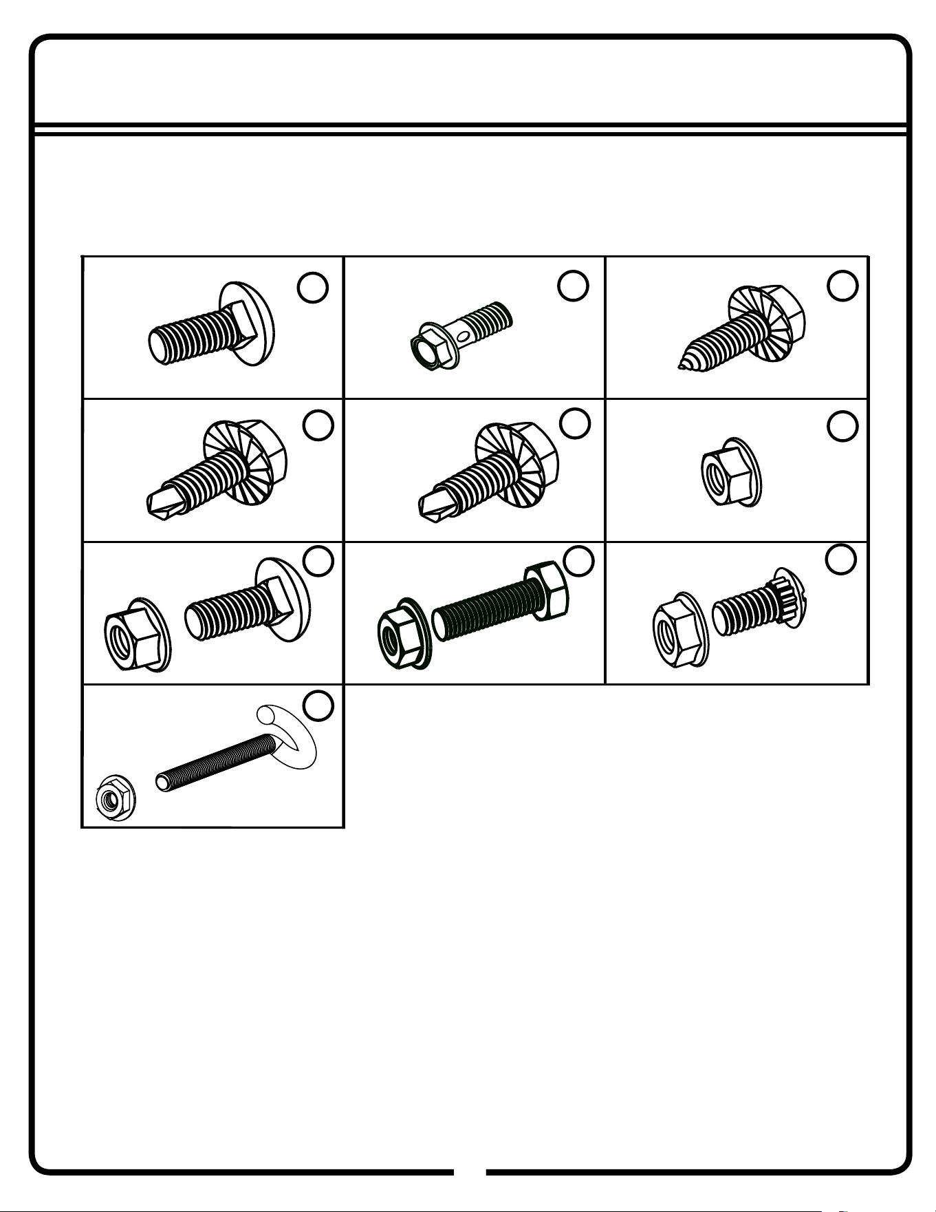
17
Hardware for Garage Door (GD)
12GW
12
Hex Bolt with
Hole
1/4” Self
Drilling Screw
1/4” Sheet
Metal Screw
10-24 x 5/8”
Bolt
1/4” Wiz Nut
1/4” x 5/8” Track Bolt
& Hex Nut
3/8” x 1-1/2” Bolt
& Hex Nut
3/8” x 3/4” Carriage Bolt
& Hex Nut
1/4” Self
Drilling Screw
Red
2
1 42
4
8
1
2 4
14
Eyebolt & Hex Nut
2
10
64
9
42
42
22
71
8
42
65
10
14
14
14
14
68
36
8
71
6
5
62
32
37
61
ASSEMBLY OVERVIEW
13GW
13
9
64
22
67
65
10
14
14
14
14
66
16
66
16
16
66
6
5
35
35
73
60
20
20
19
19
54
13
13
42
42
21
21
17
17
40
Extension Kit x1
53
49
50
50
51
51
63
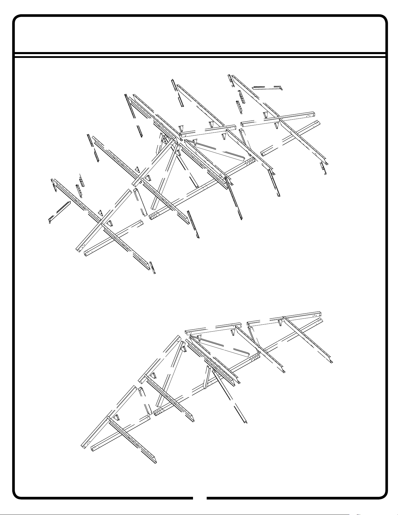
10
ASSEMBLY OVERVIEW
14GW
14
44
44
45
46
46
48
48
43
43
47
47
7
7
7
7
7
7
7
1
1
44
44
45
46
46
48
48
43
43
47
47
1
1
12
12
12
12
12
12
Extension Kit x1
2
2
3
3
4
2
2
3
3
4
7
7
7
7
7
12x10 Unit
52
52
52
52
39
39
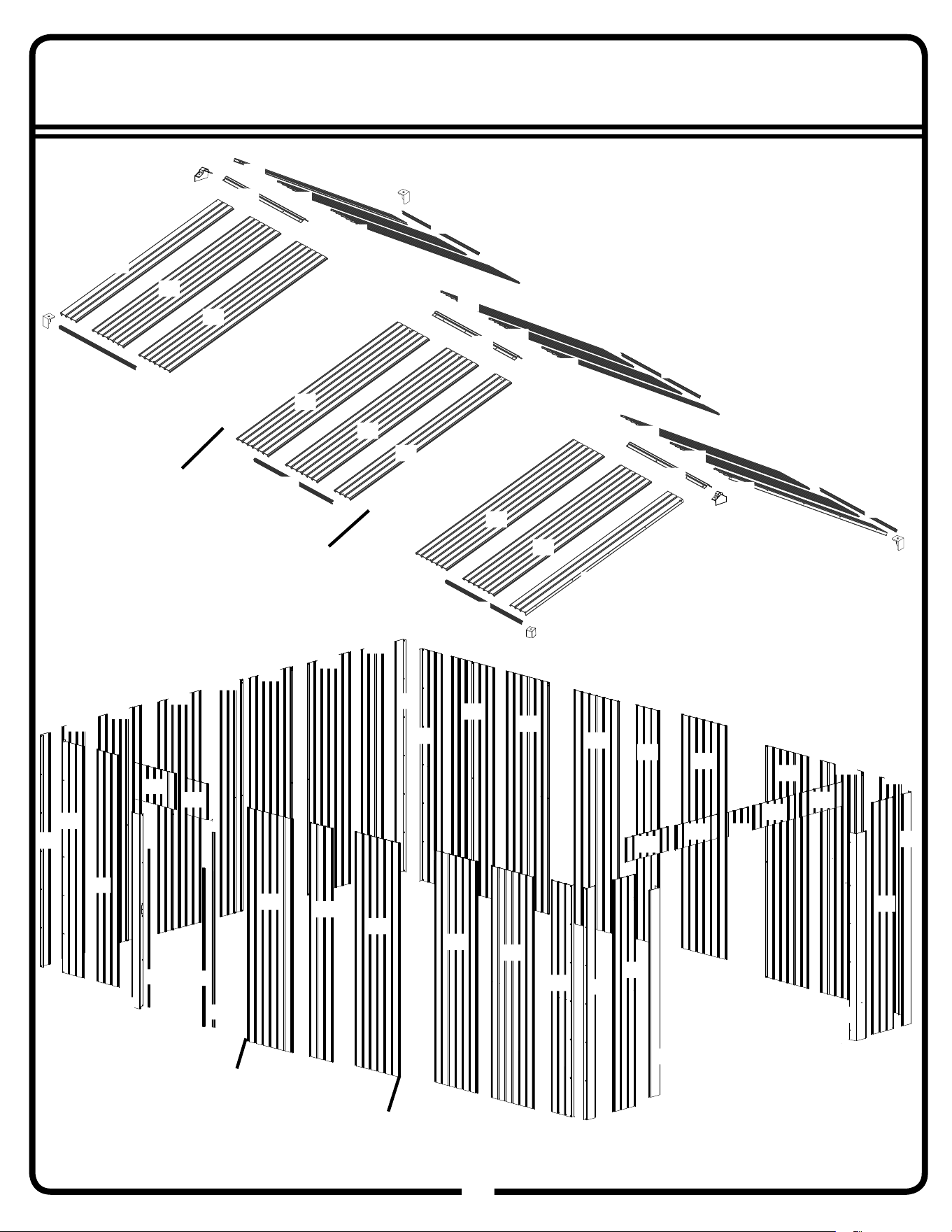
10
ASSEMBLY OVERVIEW
15GW
15
15
15
15
15
15
15
15
23
15
15
15
23
59
26
18
38
70
28
28
28
28
29
25
72
23
23
23
15
15
15
15
11
11
11
11
24
24
24
24
30
30
30
30
30
30
30
30
31
31
34
69
55
58
57
57
56
56
27
41
30
30
30
30
34
69
55
57
57
Extension Kit x1
Extension Kit x1
33
33
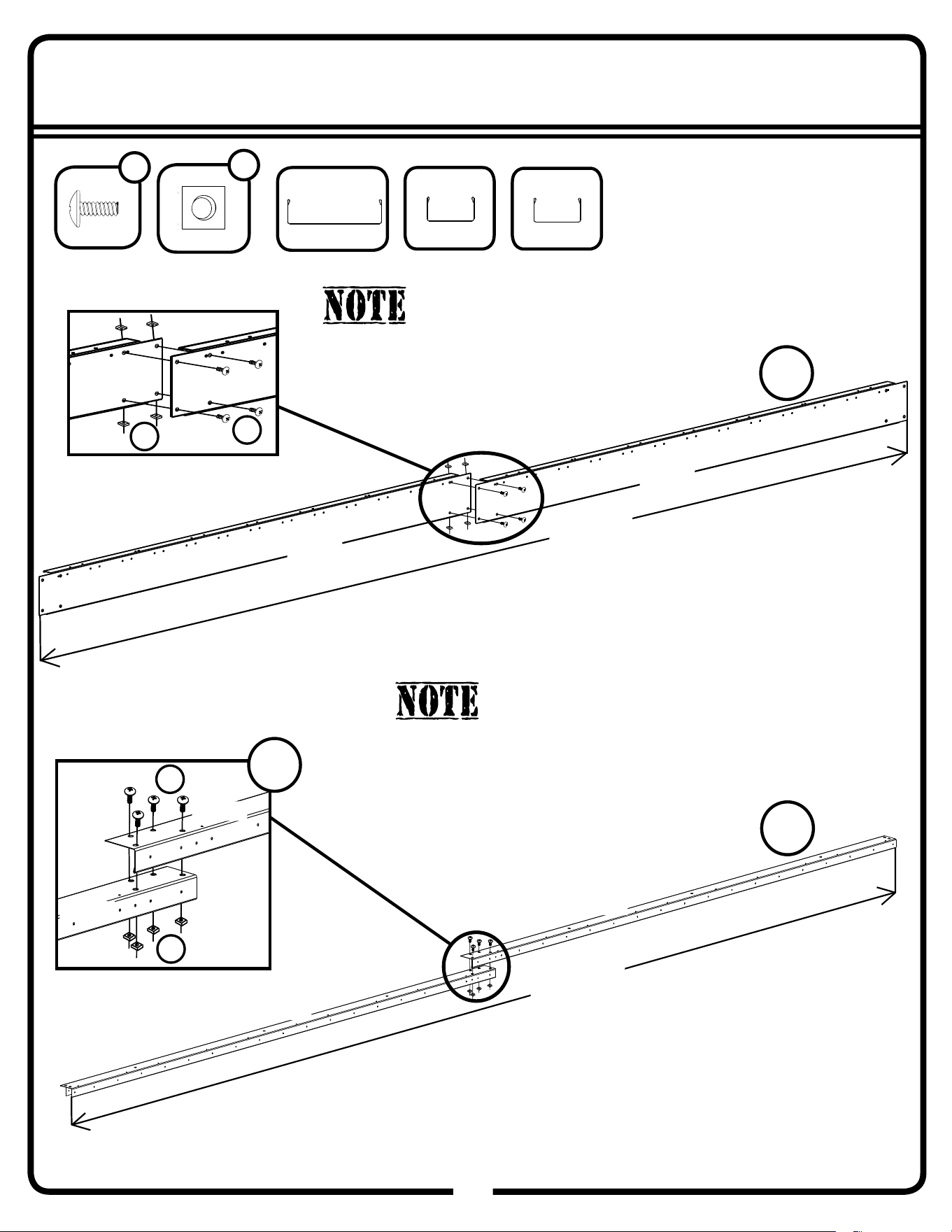
Step 1A
16
16GW
11162
(x2)
65943
BB
(x12)
65106
N
(x12)
N
N
BB
BB
11’ 7-9/16”
354,5 cm
8’ 8-3/4”
266,0 cm
80159
11150
11162
11162
x2
x2
x1
80159
(x2)
11150
(x2)
Washers are to be used on painted parts only.
Washers are not necessary on unpainted parts and
there are not enough to use on every screw and bolt.
11162
11162
80159
11150
Painted screws are to be used on
painted parts only.
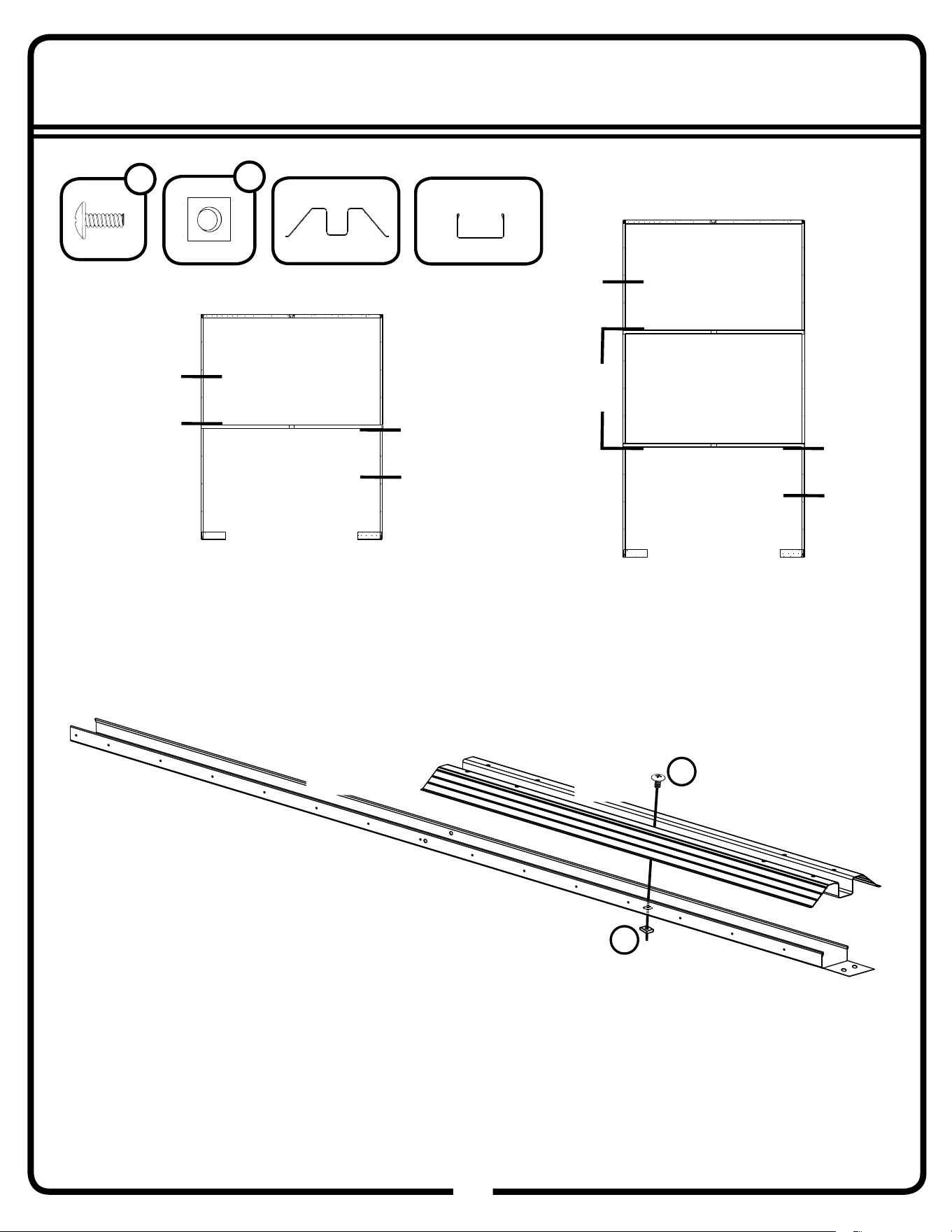
Step 1B
17
17GW
11292
(x1)
11292
80141
Door
Option A
Door
Option B
Front
Rear
For Door Option A, put the ramp on the left rear frame.
For Door Option B, put the ramp on the right front frame.
80141
(x1)
Door
Option B
Door
Option A
Rear
Front
12x10
12x15
Extension
Kit
BB
N
65943
BB
(x1)
65106
N
(x1)
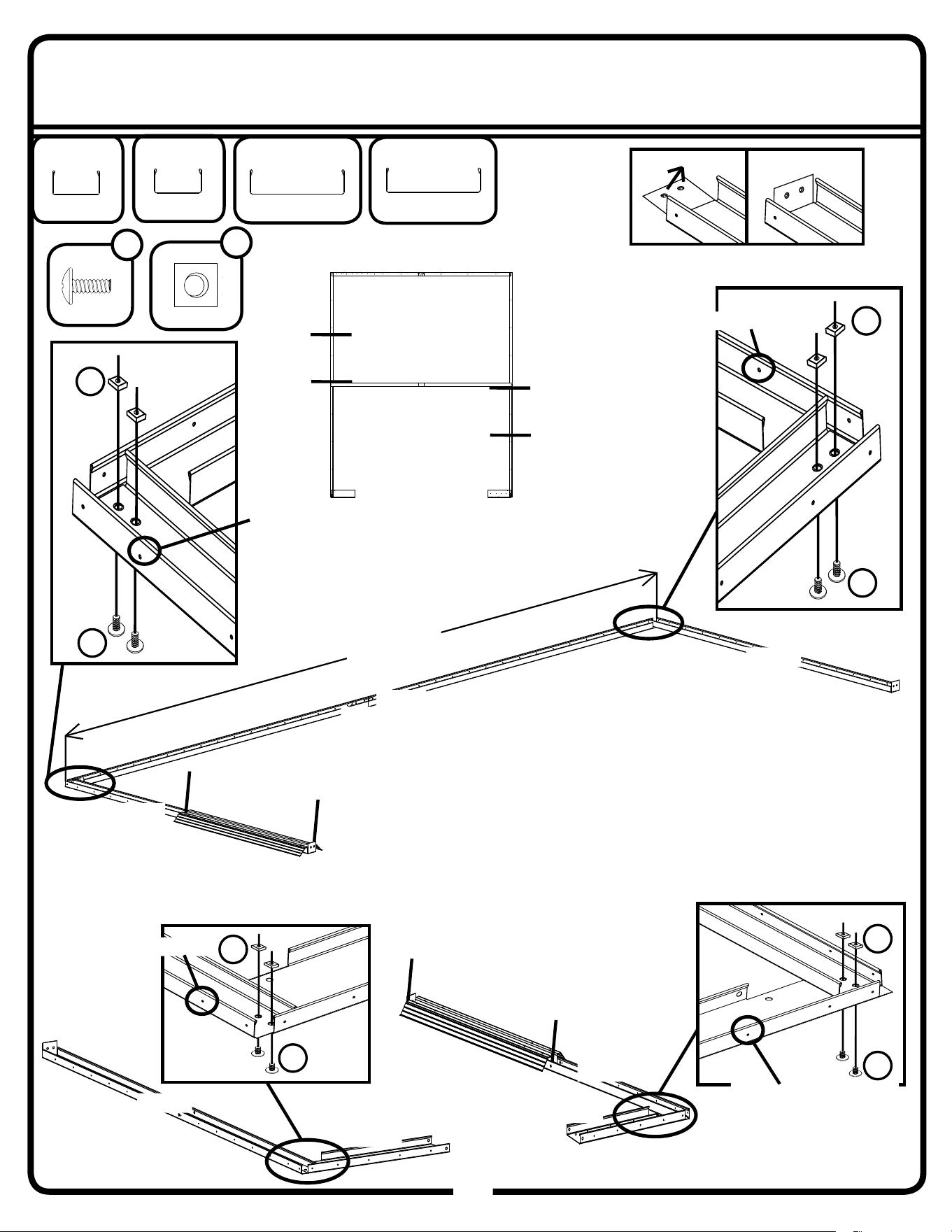
Step 1C
18
18GW
N
80141
(x1)
11151
(x2)
80145
(x1)
11158
(x1)
BB
BB
N
N
N
BB
BB
*Bend tabs up for 80141 and 11151
Rear
Front
11151
80145
11158
80141
11151
From Step 1A
*Holes on Outside
*Holes on Outside
From Step 1B
Door
Option A
Door
Option B
For Door Option A, put the ramp on the left rear frame.
For Door Option B, put the ramp on the right front frame.
11’ 9-1/8”
358,5 cm
Door
Option A
Door
Option B
Front
Rear
12x10
*Holes on Outside
*Holes on Outside
65943
BB
(x8)
65106
N
(x8)
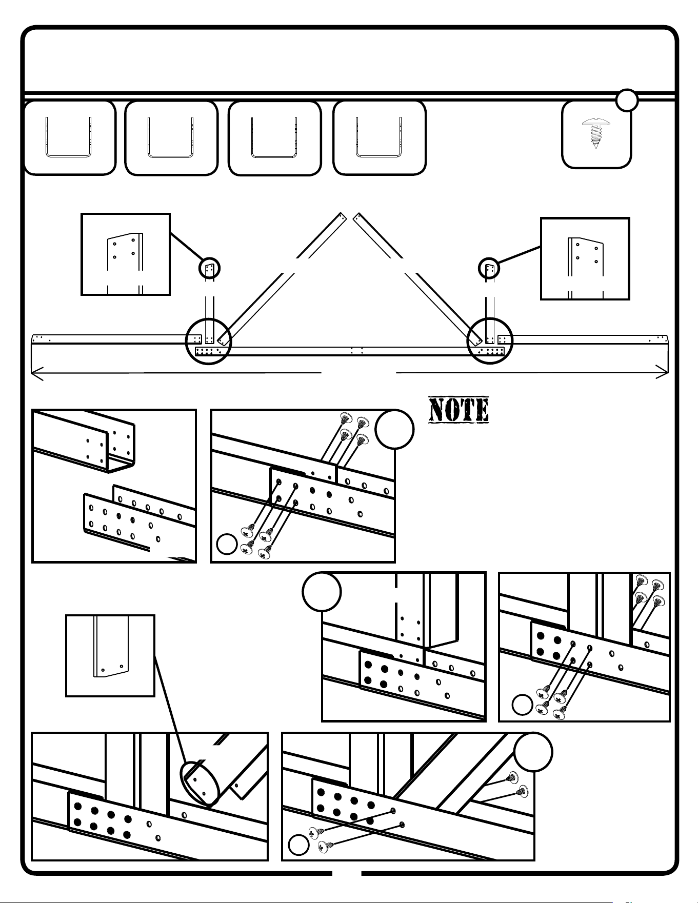
Step 2A
19
19GW
66611
BS
(x40)
11188
(x2)
11190
(x2)
11192
(x2)
11189
(x1)
11’ 3-3/4”
(344,8 cm)
BS
BS
BS
*Lubricate screws
to aid assembly
11188
11190
11192
11189
11188
11190
11192
x2
x2
x2
12x10 x1
Extension x1
11190
11190
11188
11189
11190
11192
Washers are to be used on
painted parts only. Washers
are not necessary on
unpainted parts and there are
not enough to use on every
screw and bolt.
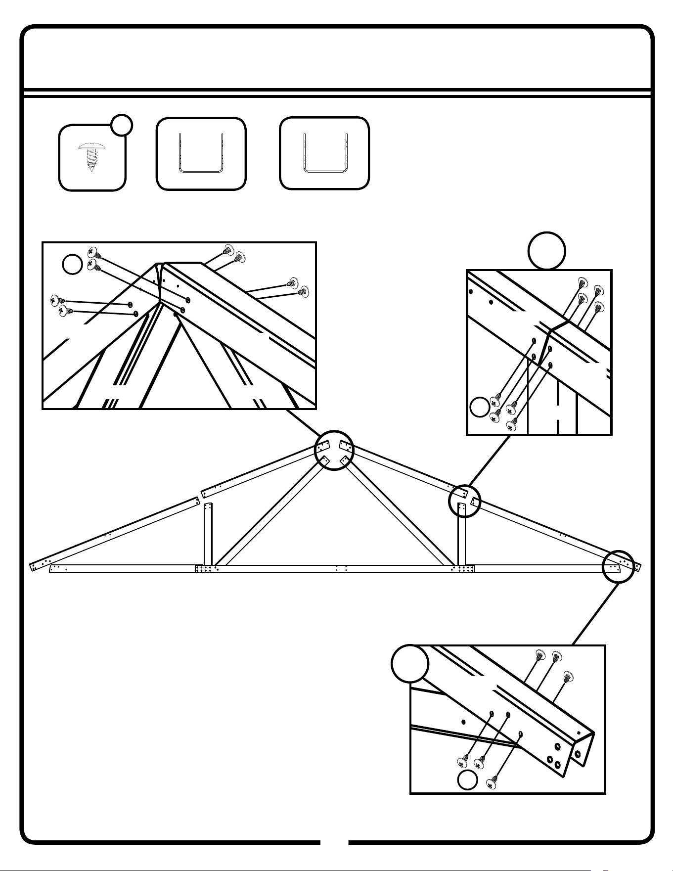
Step 2B
20
20GW
11187
(x2)
11191
(x2)
x2
x2
11187
11187
11191 11191
11191
11191
1119211192
11191
11187
11187
11190
11188
BS
BS
BS
*Lubricate screws
to aid assembly
66611
BS
(x36)
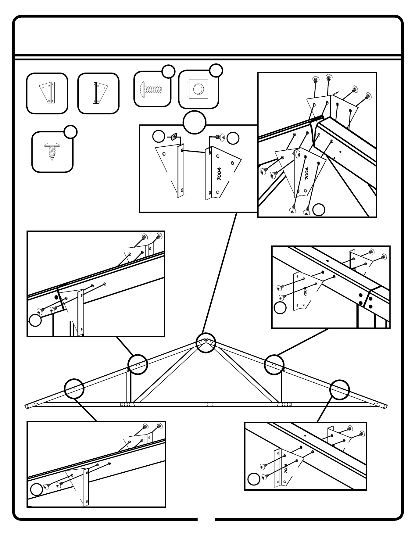
Step 2C
21
21GW
7003
7003
7004
7004
(x6)
(x6)
BS
BS
BS
BS
BS
BB
N
x2
Hand tighten bolt
7003 7004
7003
7003
7003
7003
7004
7004
7004
7004
*Lubricate screws
to aid assembly
65943
BB
(x2)
65106
N
(x2)
66611
BS
(x24)
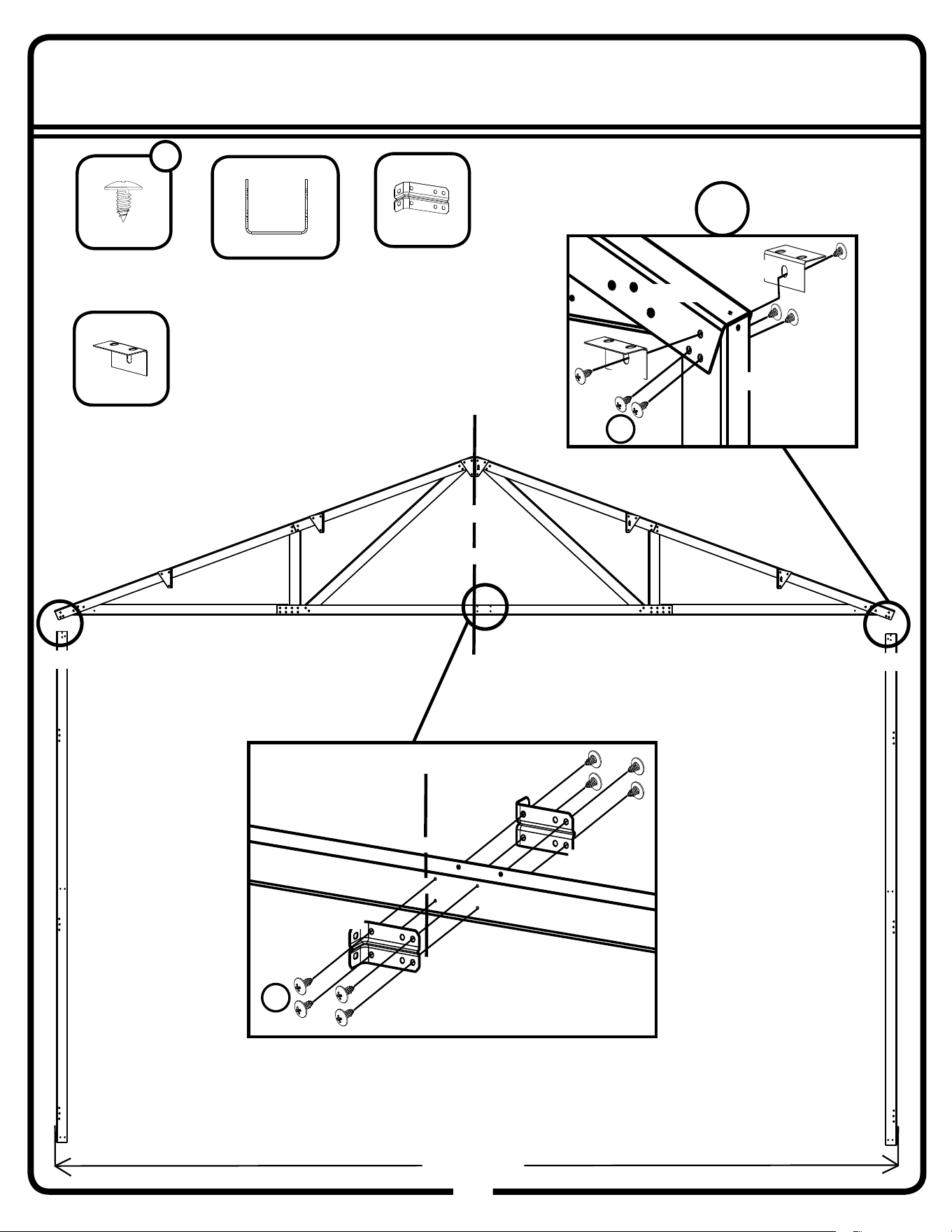
Step 2D
22
22GW
6228
(x2)
11186
(x2)
BS
BS
7022
(x4)
x2
11186
11186
11’ 9-1/8”
(358,5 cm)
7022
7022
11186
11187
6228
6228
11189
Tab end to center
of building
*Lubricate screws
to aid assembly
66611
BS
(x20)
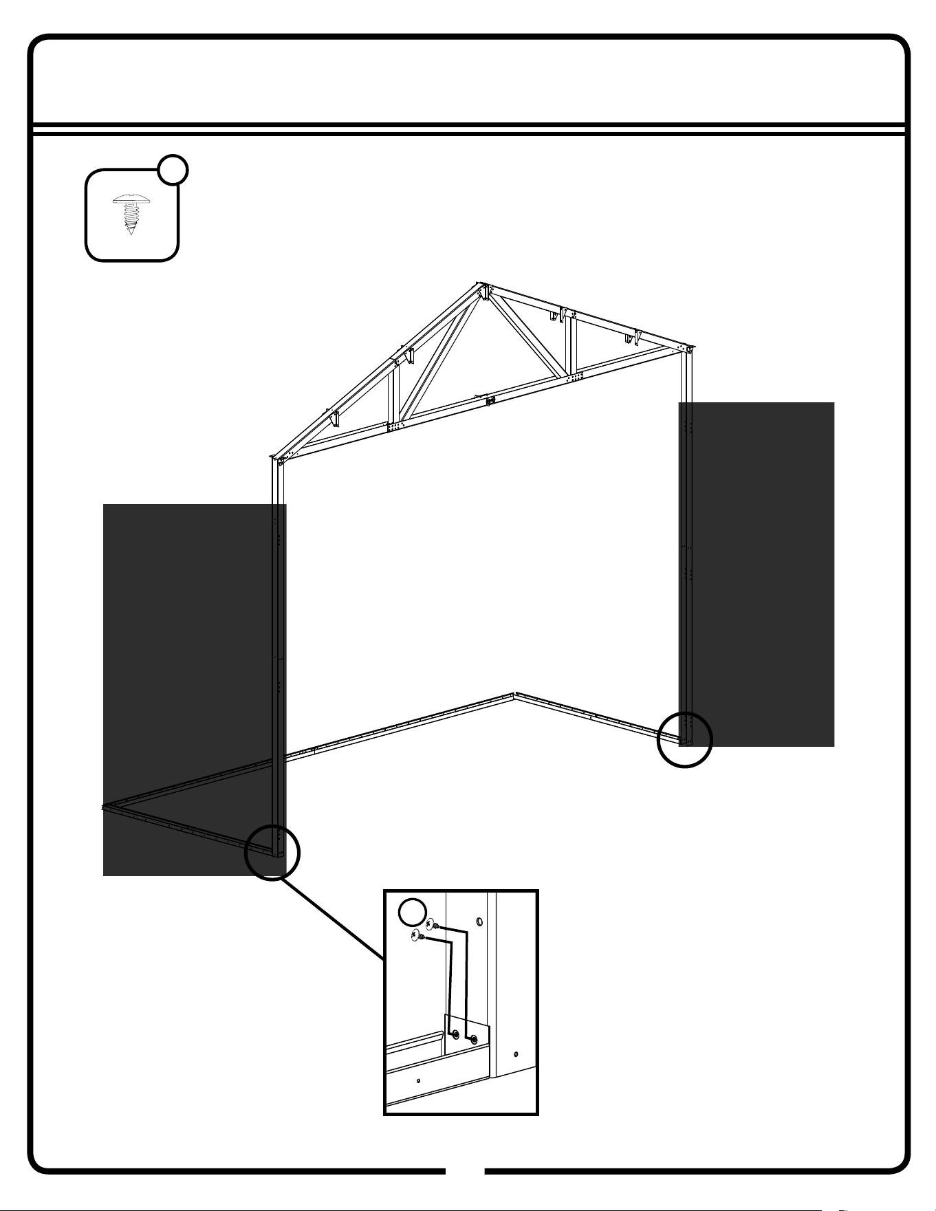
Step 3A
23
23GW
Front
Rear
BS
12x10
12x15+
Skip to Step 6A
pg 29
Continue on
Next Page
*Lubricate screws
to aid assembly
66611
BS
(x4)
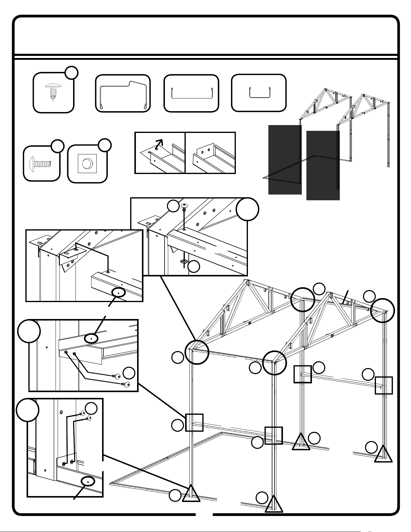
Step 3B
24
24GW
12x15+ Only
11159
(x2)
11163
(x2)
11155
(x2)
BS
BS
N
BB
*Bend tabs up for 11163 and 11155
x4
x4
x4
11159
11159
11163
11155
1
2
3
1
1
1
2
2
2
3
3
3
11155
11163
*Holes on Outside
*Holes on Outside
11159
11159
11163
11155
*Lubricate screws
to aid assembly
66611
BS
(x16)
65943
BB
(x4)
65106
N
(x4)
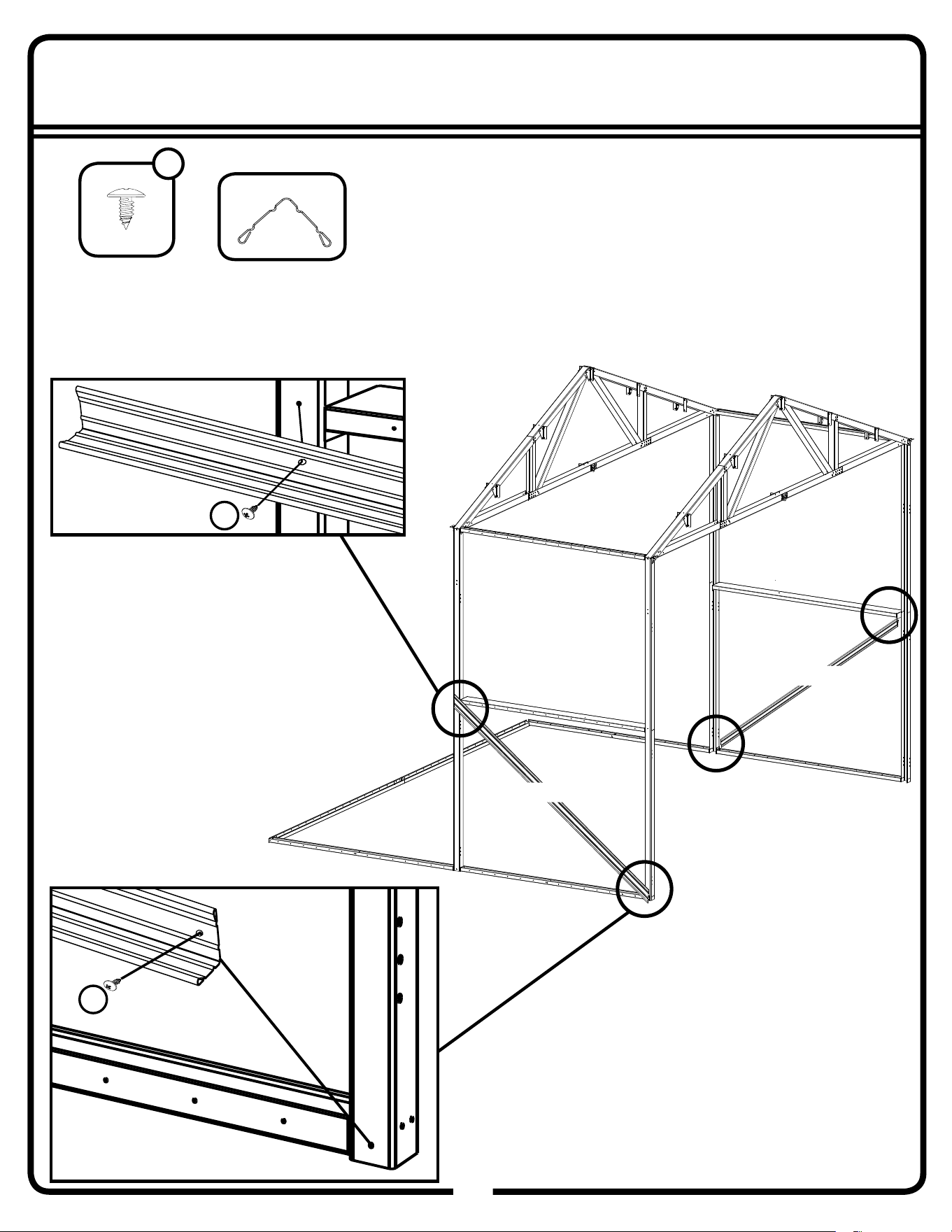
Step 3C
25
25GW
12x15+ Only
11177
(x2)
BS
BS
*11177 is for temporary use in this step
and is used in a later step
11177
11177
*Lubricate screws
to aid assembly
*
66611
BS
(x4)
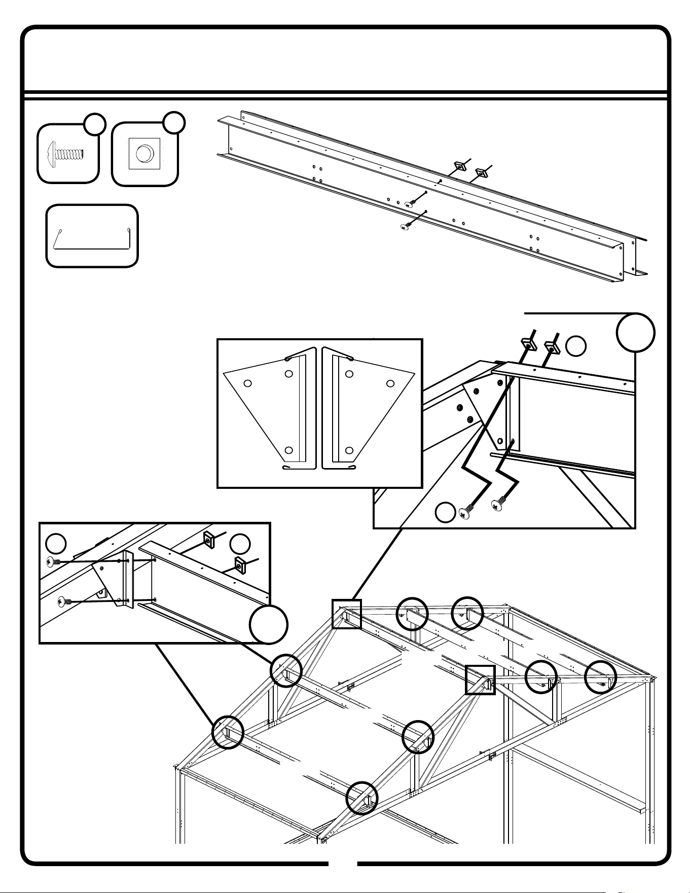
Step 4A
26
26GW
12x15+ Only
11154
(x6)
BB
BB
N
N
x8
x2
11154
11154
11154
11154
11154
Make a double roof
beam assembly
Double beam
assembly
Single roof beam
*Remove bolt linking brackets
before installing roof beams
Front View
65943
BB
(x22)
65106
N
(x22)
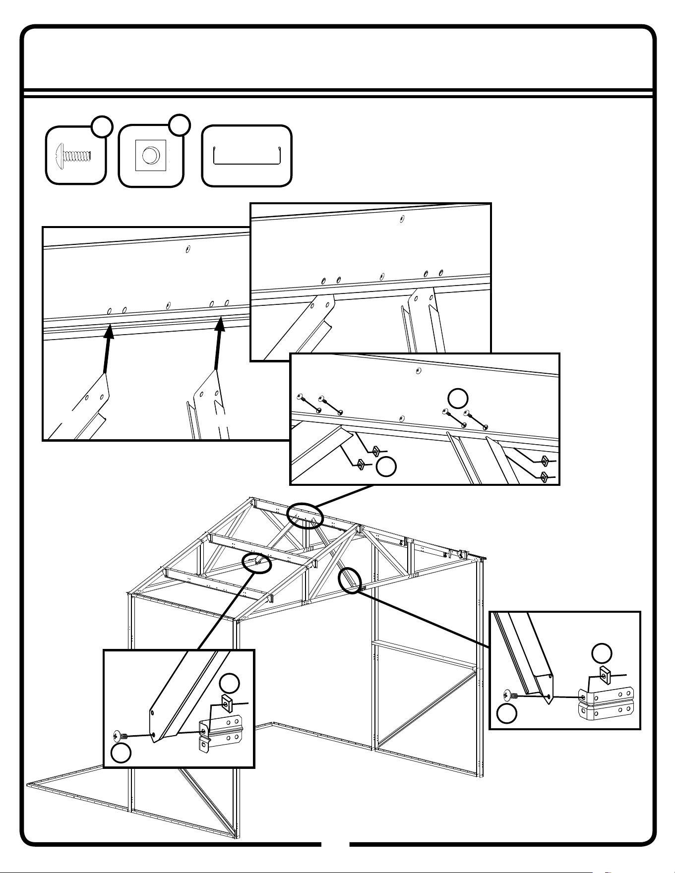
Step 4B
27
27GW
12x15+ Only
6372
(x2)
N
N
BB
BB
6372
6372
BB
N
65943
BB
(x6)
65106
N
(x6)
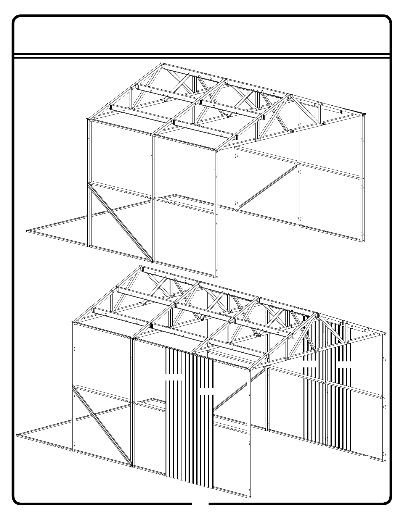
Step 5
28
28GW
12x20
*12x25+
*For buildings 25’ and longer,
attach 2 wall panels as shown
every 10’ for support. Follow
Step 12A on page 48 for screw
placement
11157
11157
11157
11157
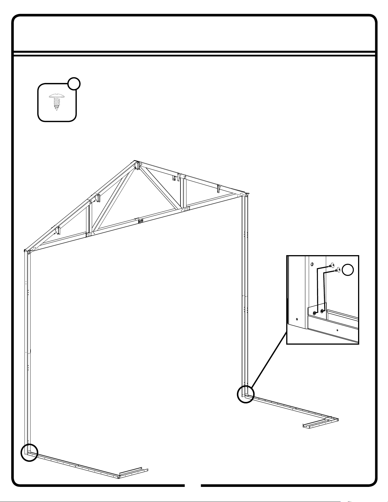
Step 6A
29
29GW
From Step 1C
12x10+ Continued
Continue supporting truss for 12x10
until frame is complete
Front
BS
From Step 1C
*Lubricate screws
to aid assembly
66611
BS
(x4)
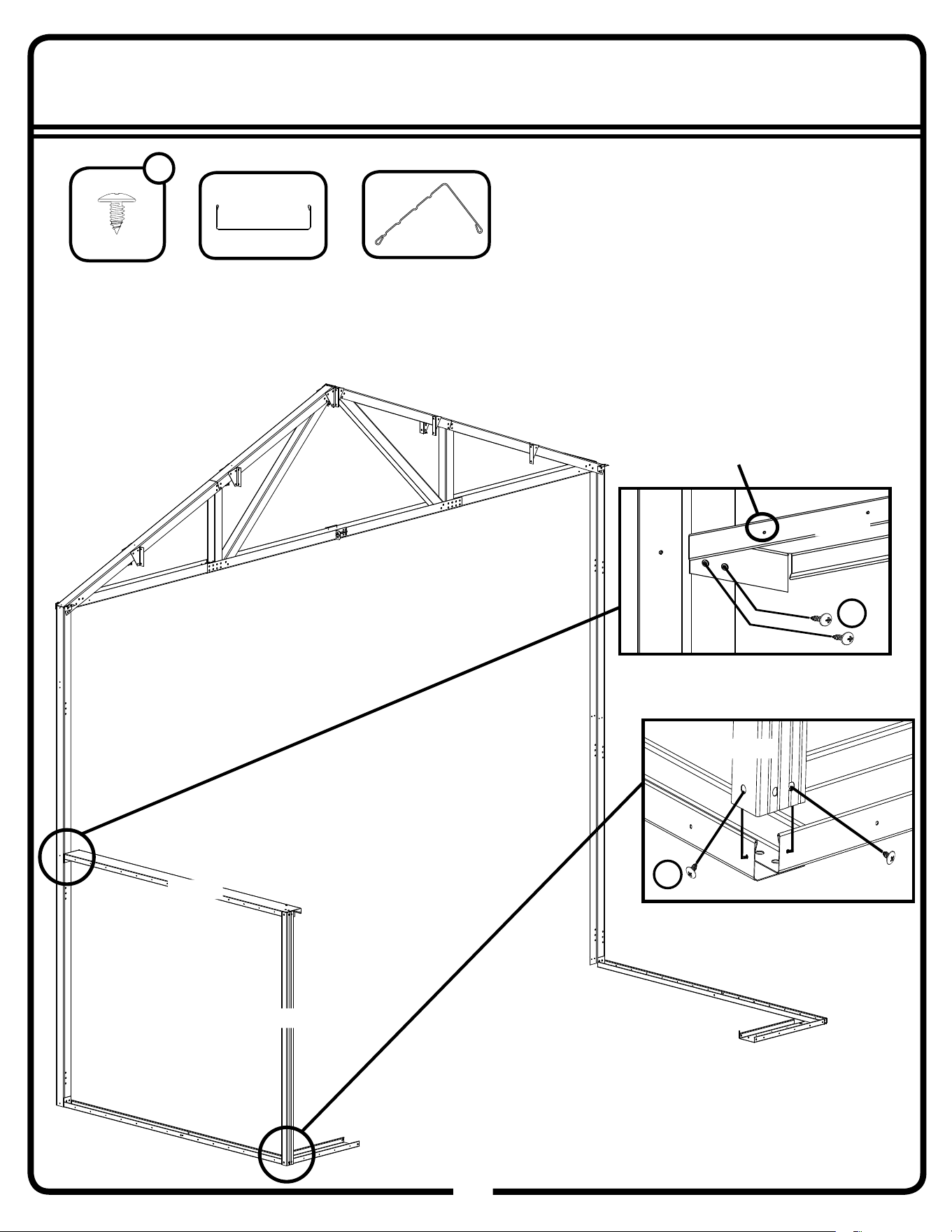
Step 6B
30
30GW
Front
11165
(x1)
11156
(x1)
BS
BS
11165
11156
*Holes on Outside
*Lubricate screws
to aid assembly
66611
BS
(x4)
11156
11165
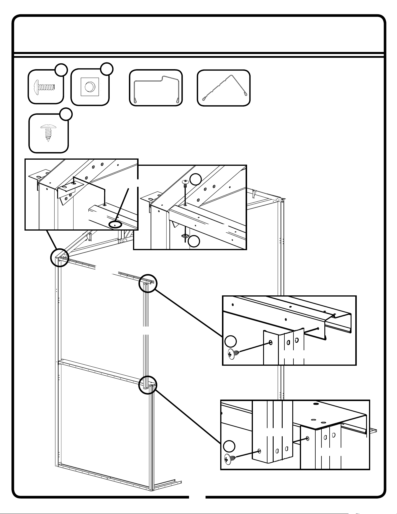
Step 6C
31
31GW
N
Front
11156
(x1)
11152
(x1)
BS
BS
BB
N
11152
11156
*Holes on Outside
66611
BS
(x2)
65943
BB
(x1)
65106
N
(x1)
11156
11156
11156
11152
11152
11152
11165
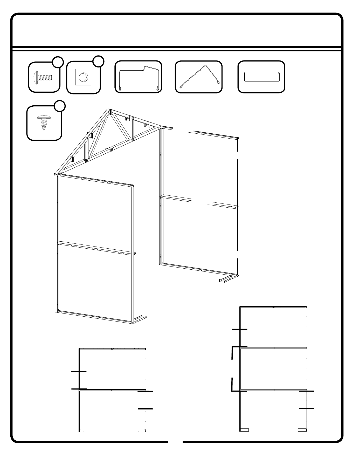
Step 6D
32
32GW
Front
For Door Option B,
follow Step 9 on page
39 in place of this step
1
1156
(x2)
80143
(x1)
80147
(x1)
80143
80147
11156
11156
Repeat Steps 6B and 6C
for the other side with
holes facing outside
Door
Option A
Door
Option B
Front
Rear
Door
Option B
Door
Option A
Rear
Front
12x10
12x15
Extension
Kit
65943
BB
(x1)
65106
N
(x1)
66611
BS
(x6)
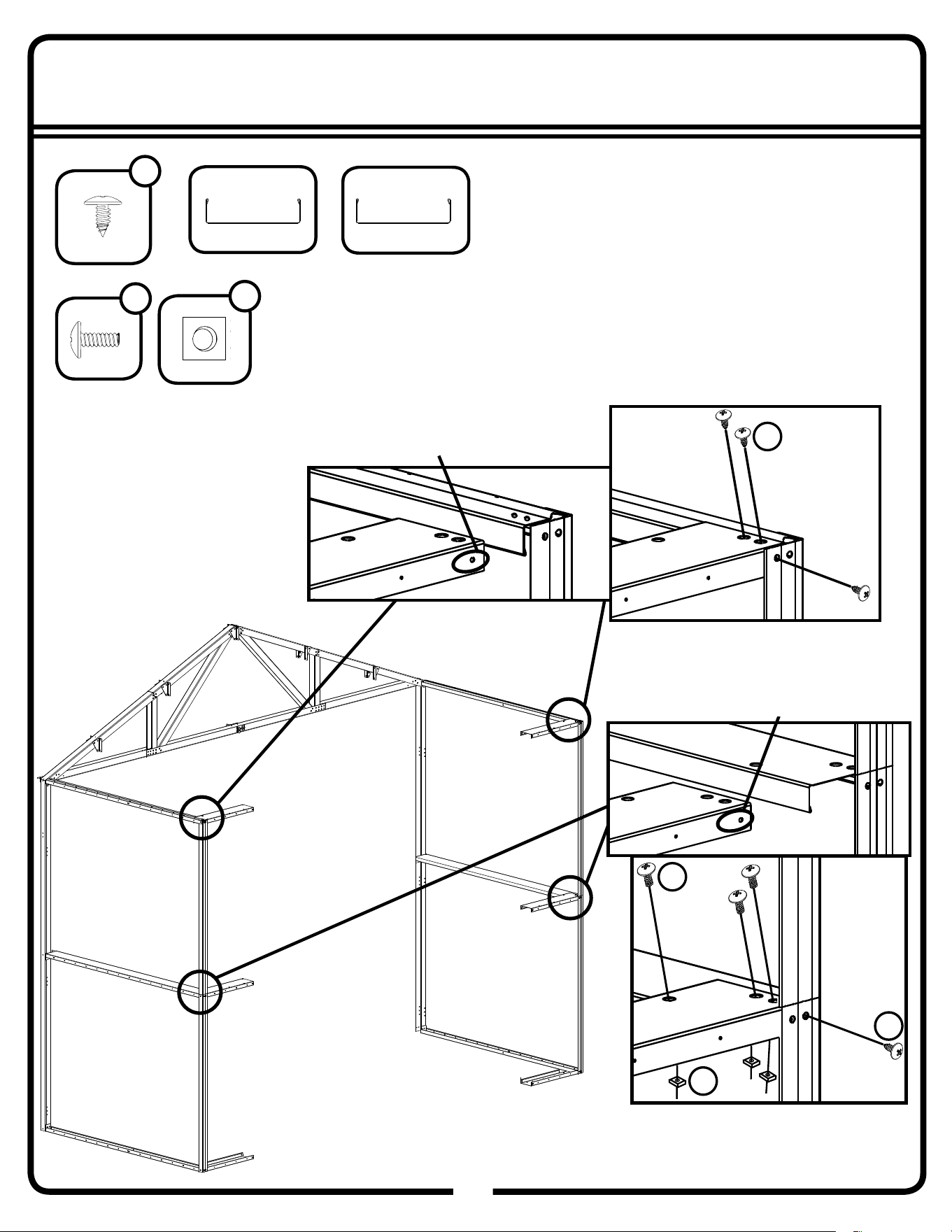
Step 6E
33
33GW
Front
11158
(x2)
80145
(x2)
BS
BS
11158
11158
80145
80145
BB
N
*Holes on Outside
*Holes on Outside
65943
BB
(x6)
65106
N
(x6)
66611
BS
(x8)
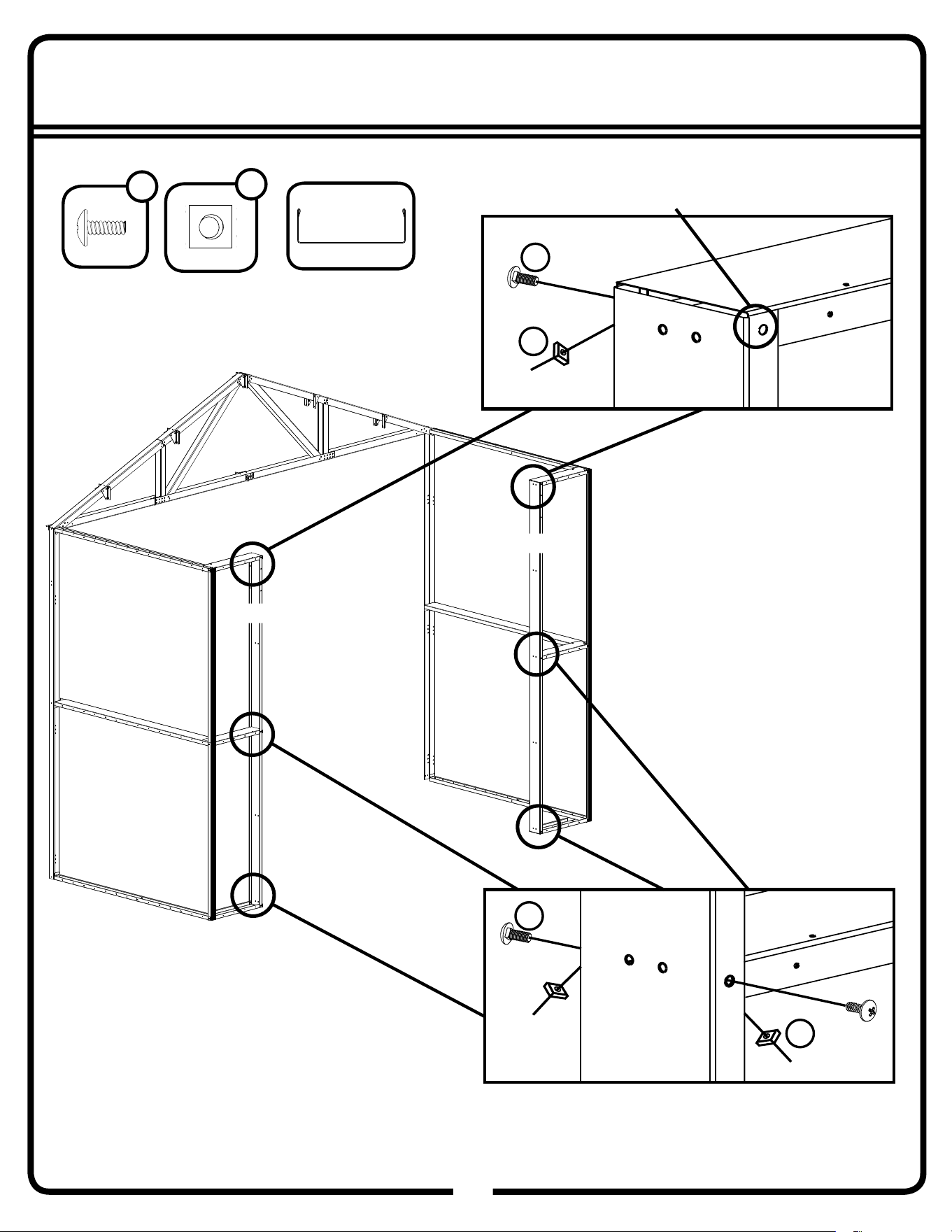
Step 7A
34
34GW
Front
*Leave outside top bolt
out for both columns
BB
N
BB
N
11179
(x2)
11179
11179
65943
BB
(x10)
65106
N
(x10)
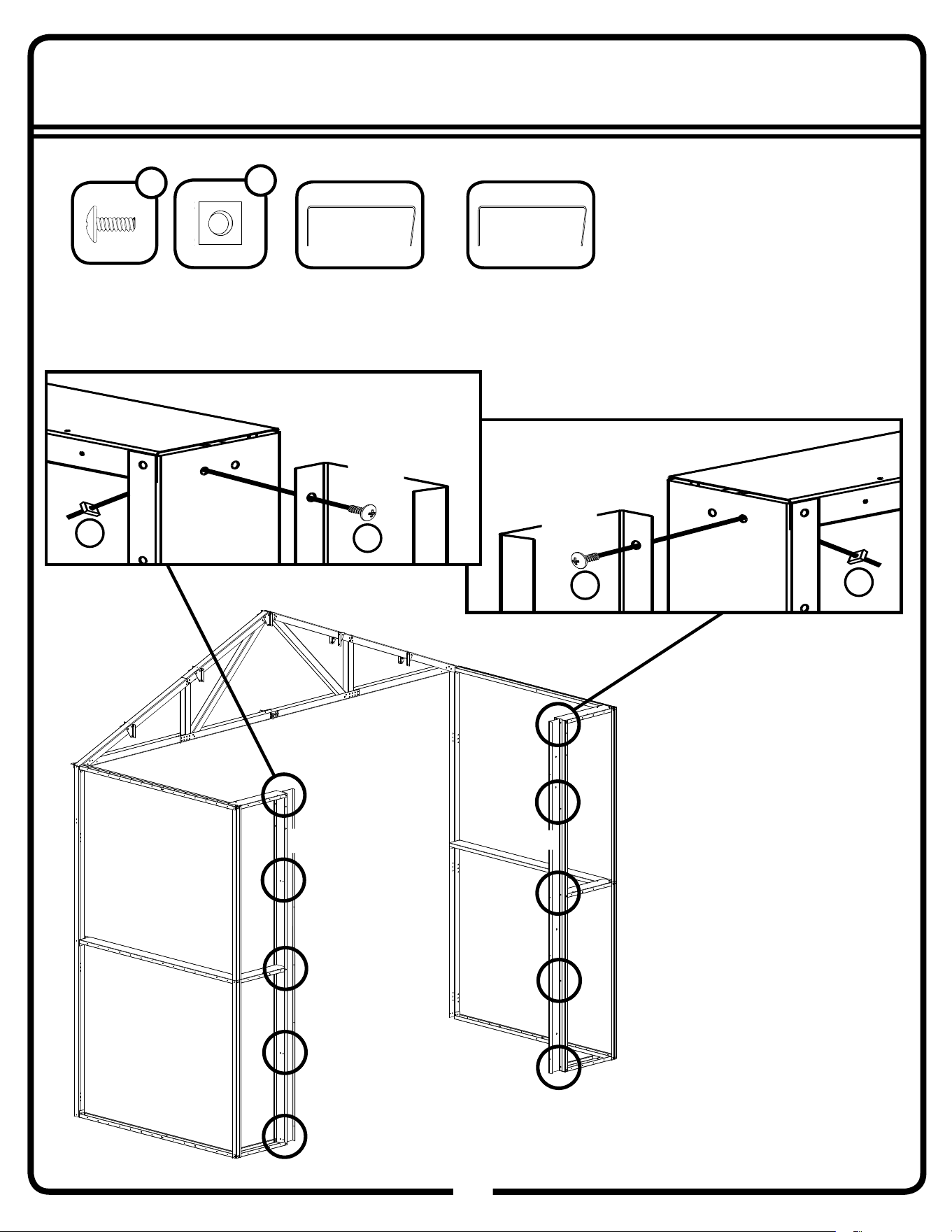
Step 7B
35
35GW
Front
BB
N
11290
(x1)
11290
80191
80191
(x1)
BB
N
80191
11290
65943
BB
(x10)
65106
N
(x10)
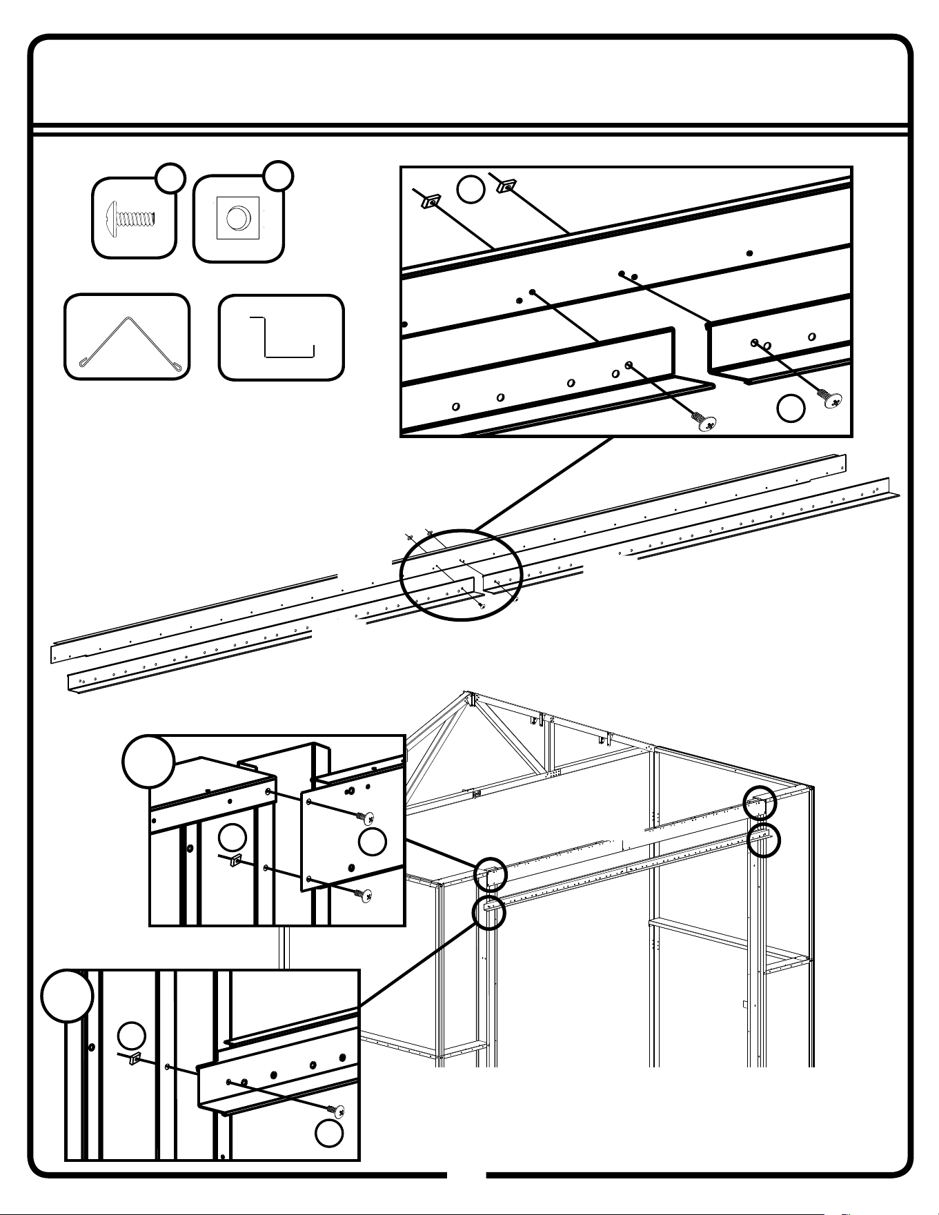
Step 7C
36
36GW
Front
BB
BB
N
N
BB
N
11161
(x2)
11201
(x1)
11161
11161
11161
11161
11201
11201
From Step 1A
x2
x2
65943
BB
(x8)
65106
N
(x8)
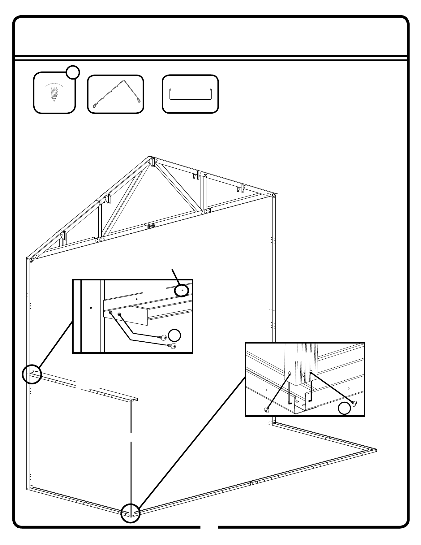
Step 8A
37
37GW
Rear
11156
(x1)
11165
(x1)
*Holes on Outside
11165
11156
BS
BS
11156
11165
*Lubricate screws
to aid assembly
66611
BS
(x4)
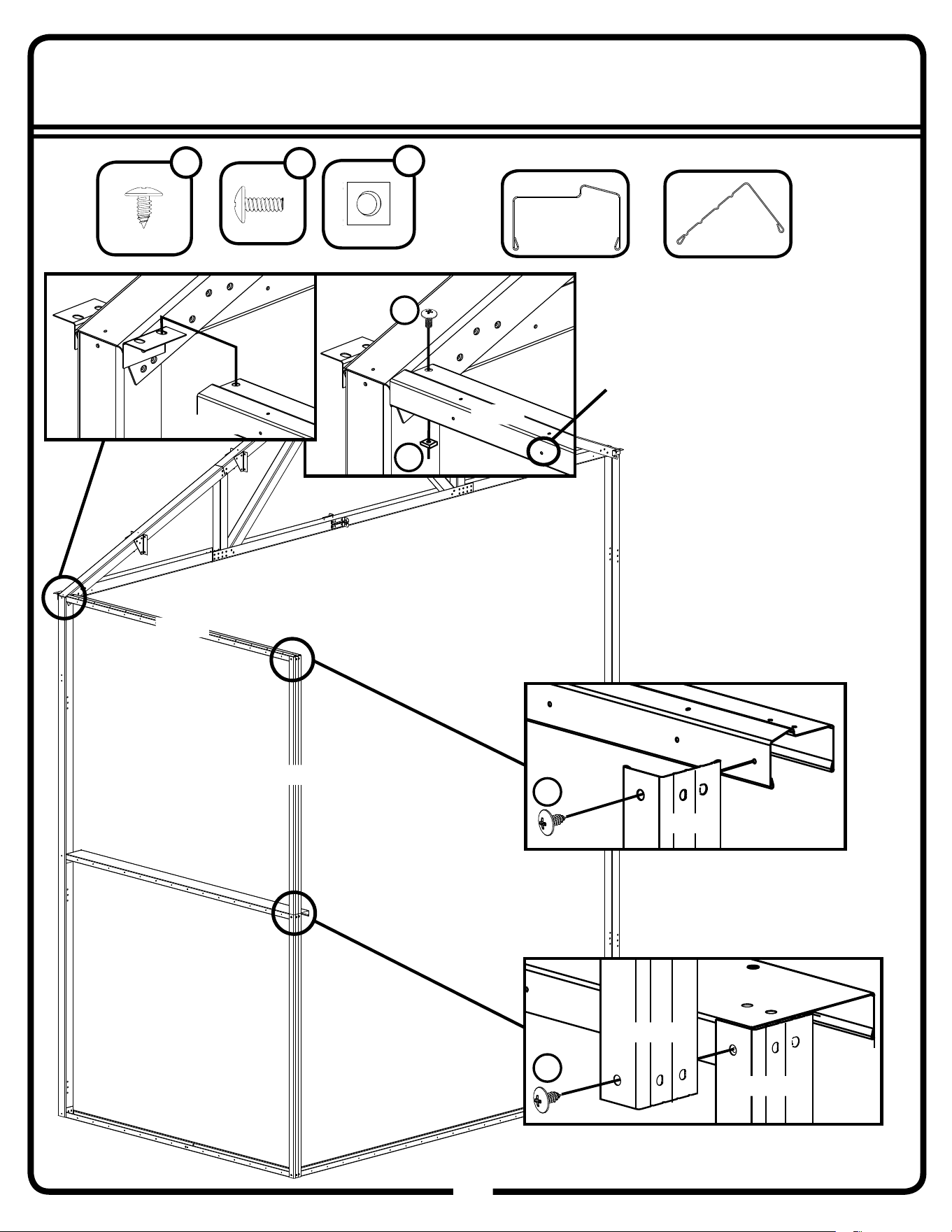
Step 8B
38
38GW
Rear
11156
(x1)
11152
(x1)
N
BS
BS
BB
11156
11152
11156
11156
11165
11152
11152
11152
11156
65943
BB
(x1)
65106
N
(x1)
66611
BS
(x2)
*Holes on Outside
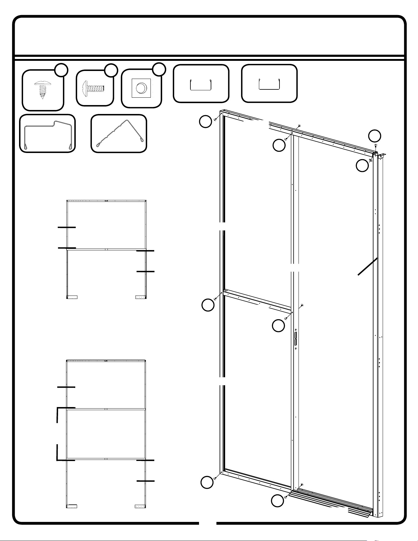
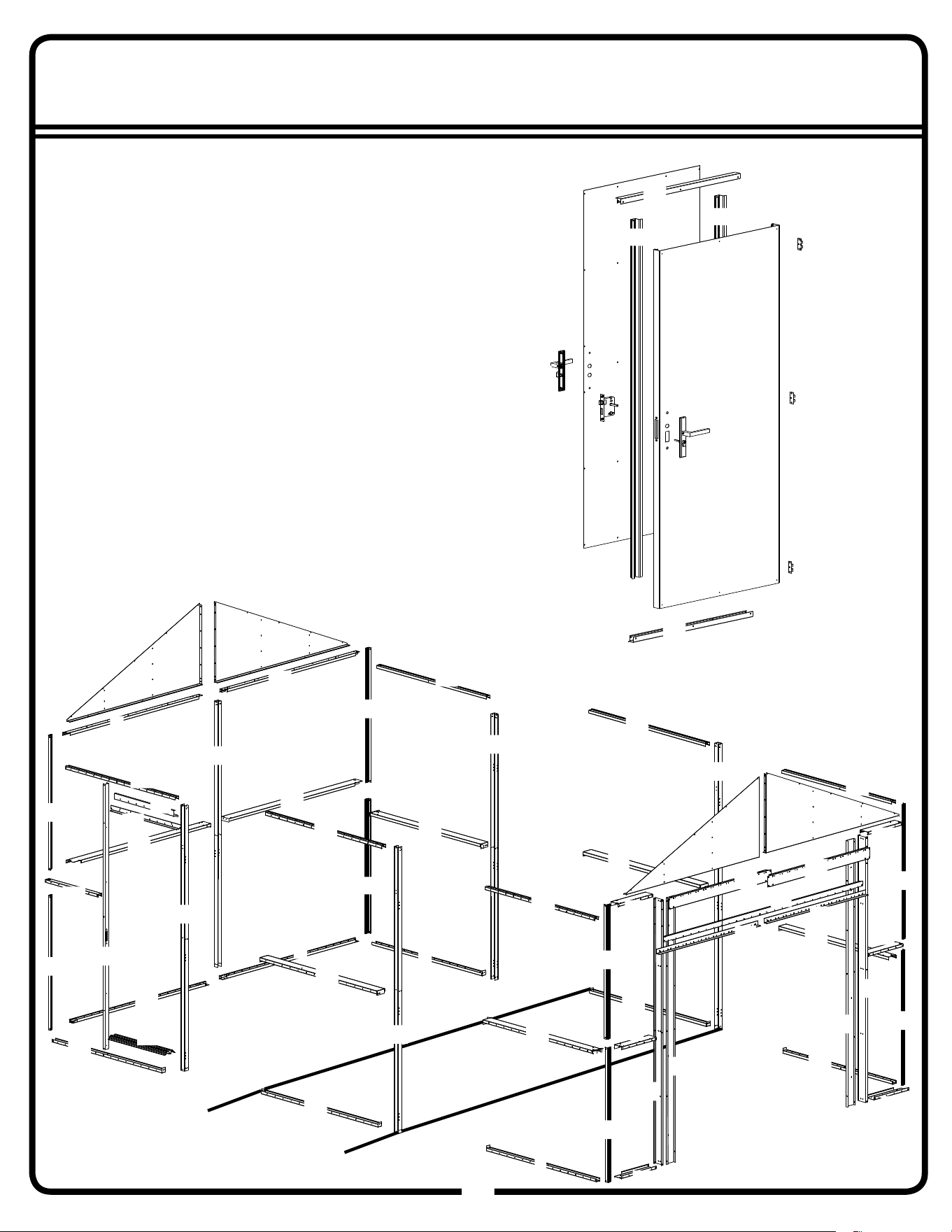
Step 9
39
39GW
11176
(x1)
11176
11184
(x1)
11184
BS
BS
BS
Truss
Column
From Step 1B
11156
11156
80143
BS
BS
N
BB
11156
(x2)
80143
(x1)
BS
For Door Option B, follow Step 6D on
page 32 in place of this step
Door
Option A
Door
Option B
Front
Rear
12x10
Door
Option B
Door
Option A
Rear
Front
12x15
Extension
Kit
65943
BB
(x1)
65106
N
(x1)
66611
BS
(x9)
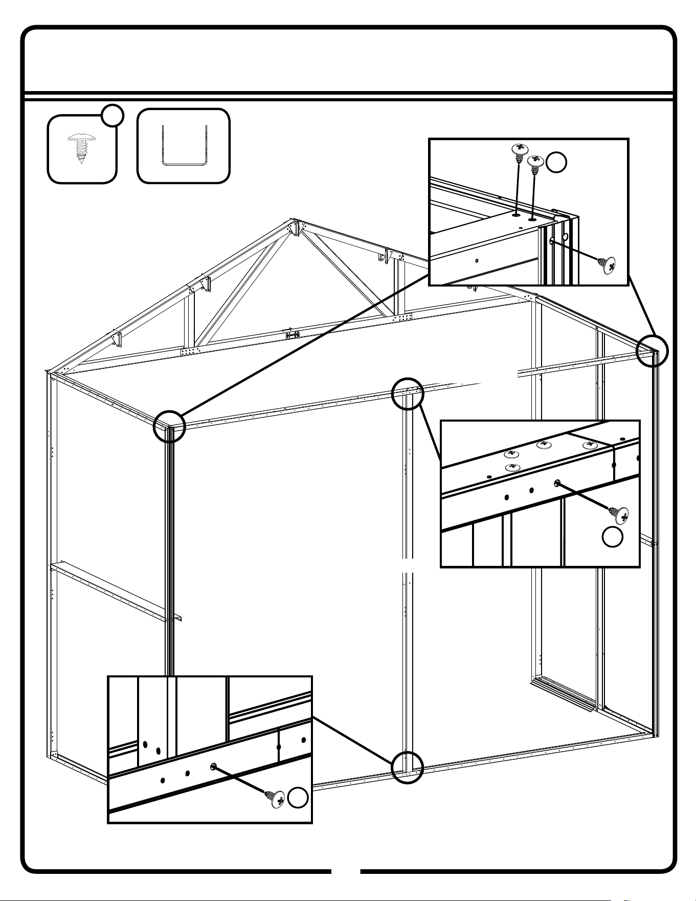
Step 10A
40
40GW
Rear
BS
From Step 1A
11186
11186
(x1)
BS
BS
*Lubricate screws
to aid assembly
66611
BS
(x8)
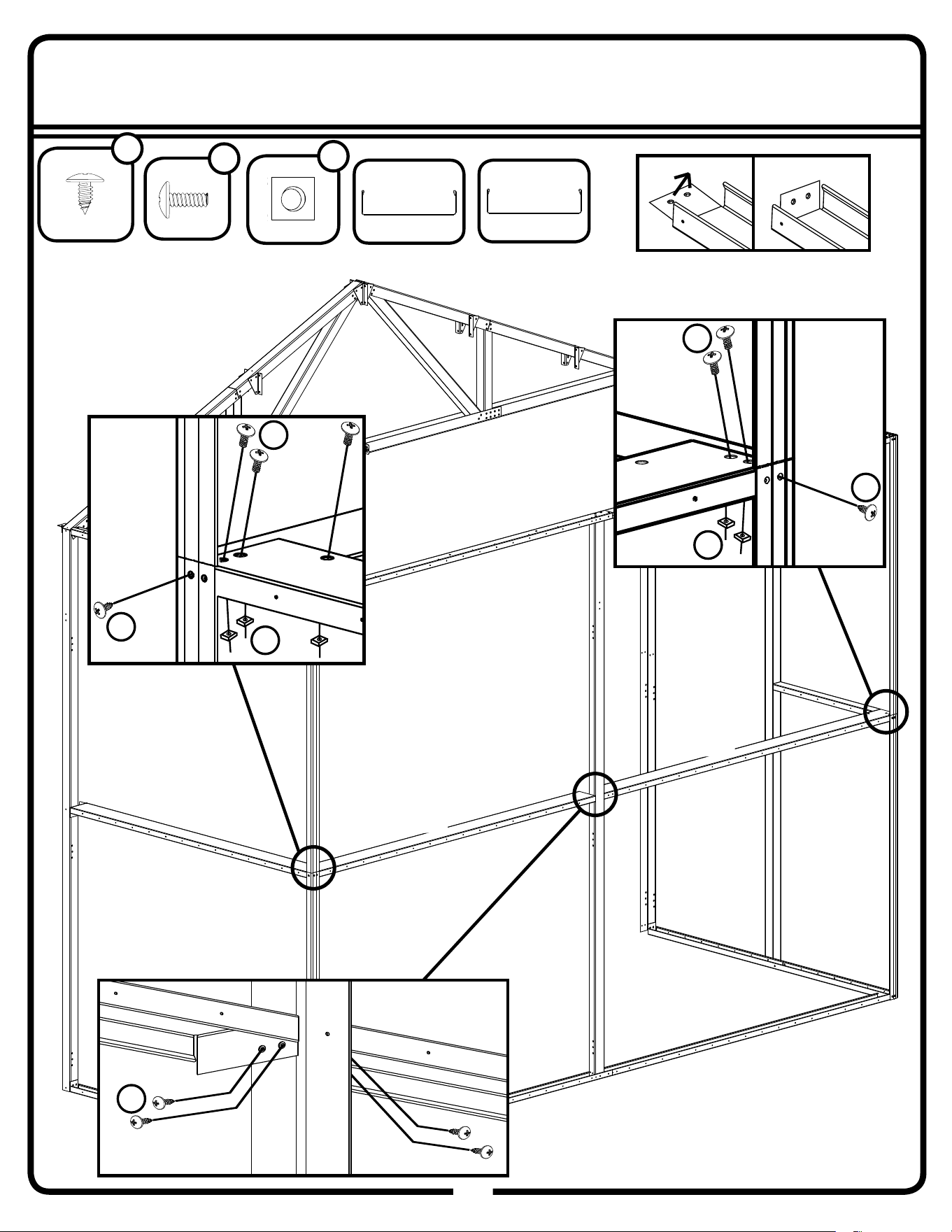
Step 10B
41
41GW
Rear
80149
11180
BS
BB
N
BB
BS
N
BS
80149
(x1)
11180
(x1)
*Bend tabs up for 80149 and 11180
*Lubricate screws
to aid assembly
66611
BS
(x6)
65943
BB
(x5)
65106
N
(x5)
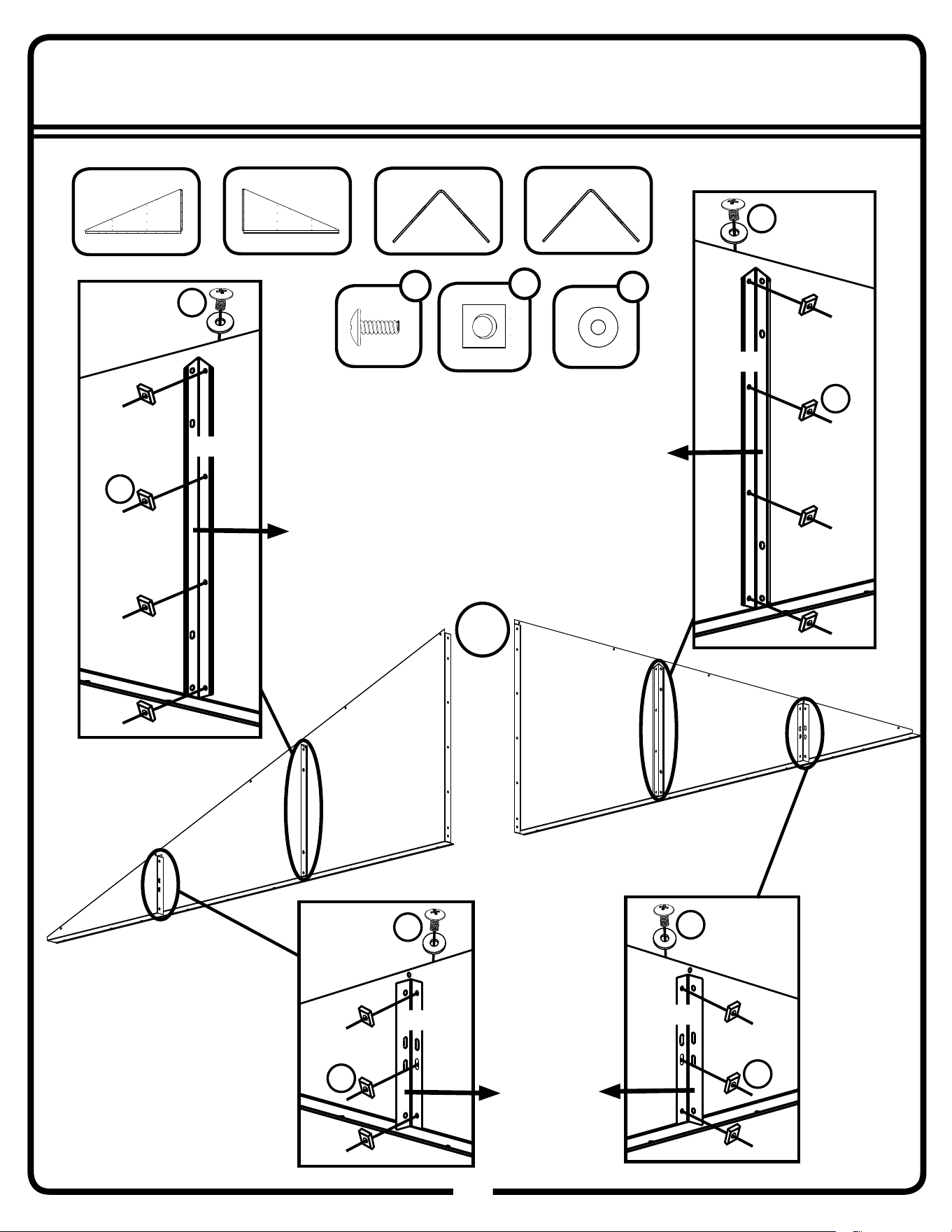
Step 11A
42
42GW
6381
(x4)
6380
(x4)
7943
(x2)
7942
(x2)
WB
WB
WB
WB
N
N
N
N
6381
6381
6380
6380
7942
7943
*Bolts to match
wall panel color
66646
W
(x28)
Mounting leg
faces inwards
Mounting leg
faces inwards
Mounting leg
faces inwards
x2
65943
WB
(x28)
65106
N
(x28)
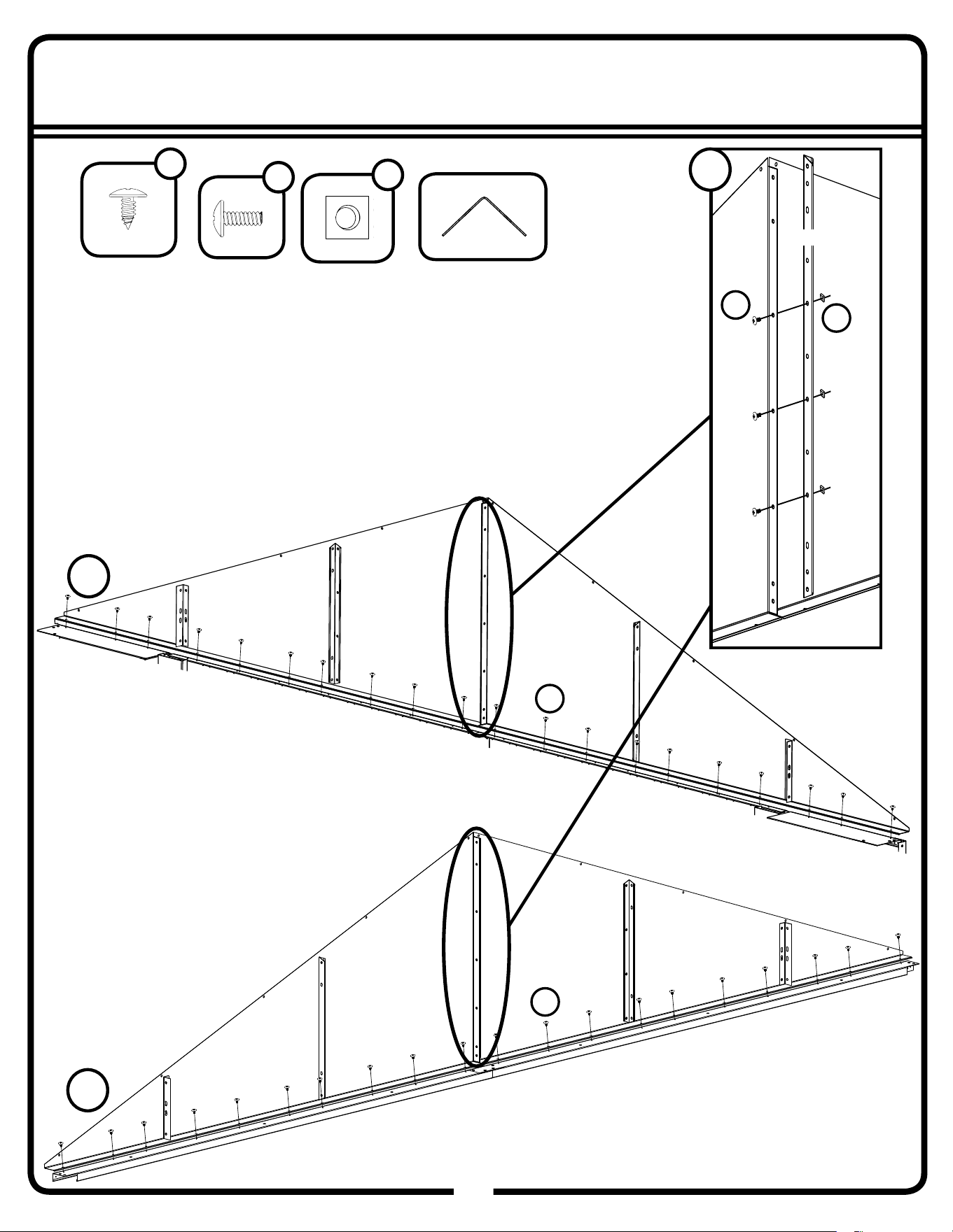
Step 11B
43
43GW
Front
Rear
BS
BS
6382
(x2)
6382
BB
N
1
2
1
65943
BB
(x6)
65106
N
(x6)
66611
BS
(x40)
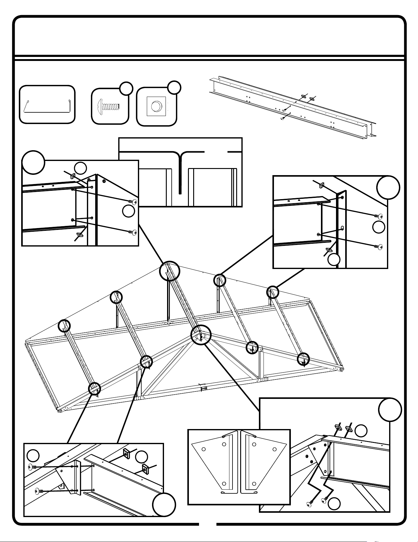
Step 11C
44
44GW
Make 2 double roof
beam assemblies
Single roof
beam
11149
(x12)
x8
BB
N
x2
Double beam
assembly
*Remove bolt linking brackets
before installing roof beams
BB
N
x8
Single roof beam
*Repeat this page for the Rear of the shed
Front View
Top View
Double beam
assembly
x2
BB
N
N
BB
Beam
Gable
65943
BB
(x44)
65106
N
(x44)
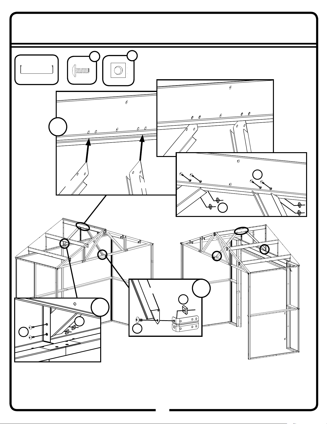
6372
6372
BB
N
Step 11D
45
45GW
Front
Rear
6372
(x4)
x2
x2
N
BB
x2
6372
BB
N
6372
65943
BB
(x14)
65106
N
(x14)
17
46GW
46
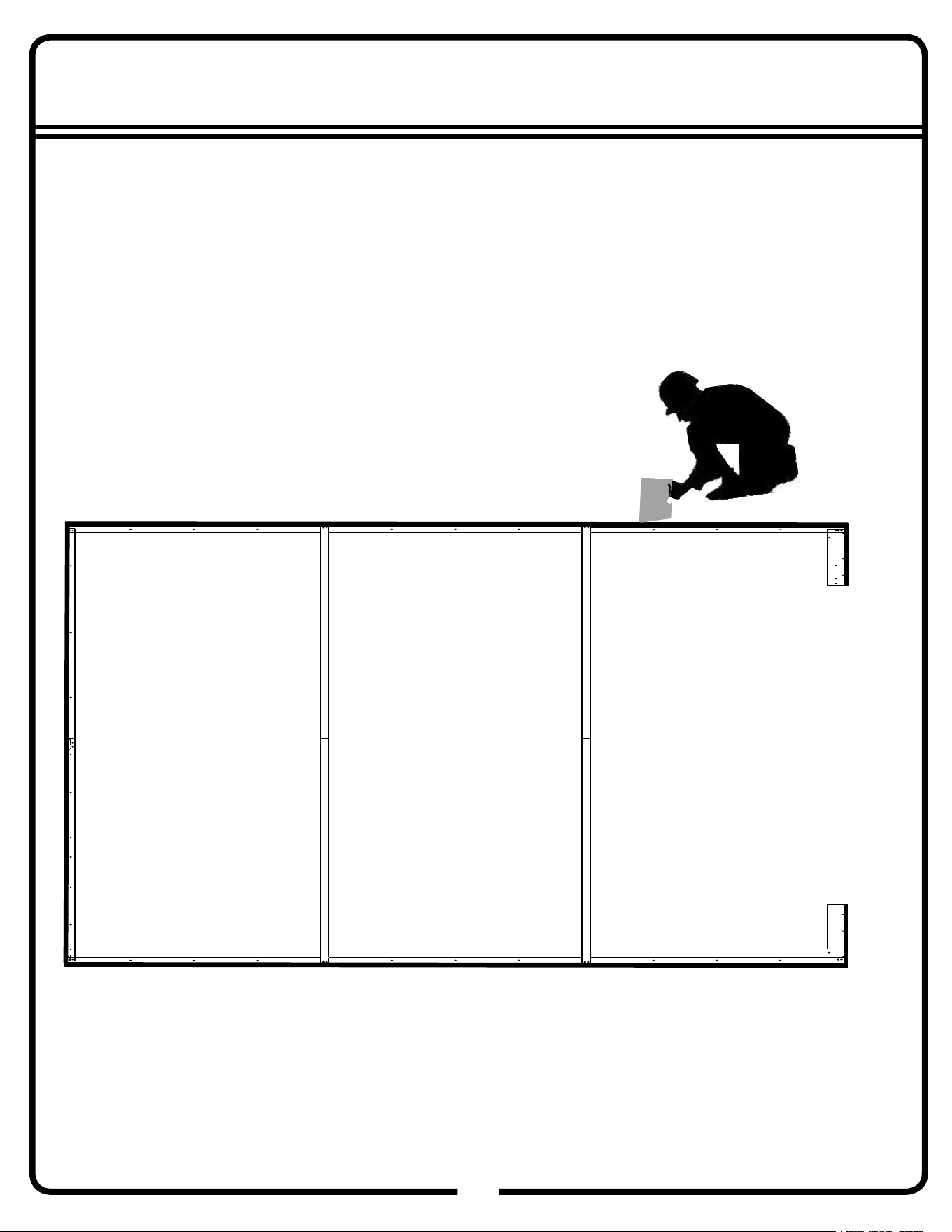
To reduce water infi ltration, apply caulk around the perimeter of the shed before
installing panels.
OPTIONAL CAULK APPLICATION
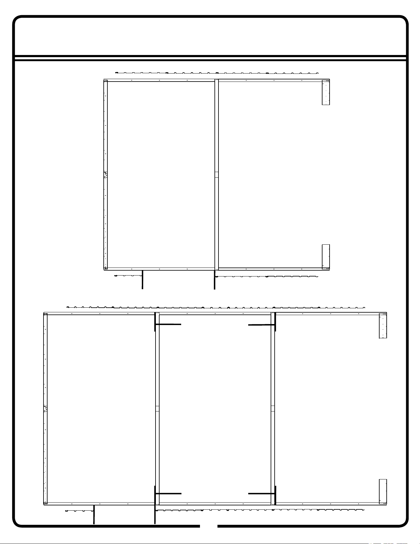
Side Panel Orientation
47
47GW
Door
Option
A
Front
Rear
12x10
11160
11157
11157
11157
11157
11157
11157
11157
11157
11157
11157
11166
11157
11157
11157
11157
11157
11157
11166
11160
12x15
Front
Rear
Door
Option A
Extension Kit(s)
Extension Kit(s)
Step 12A
48
48GW
1
2
3
11157
11157
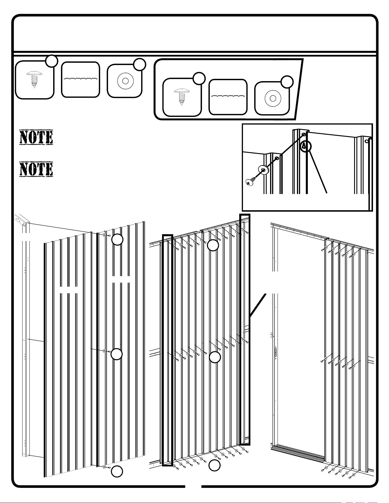
Install 2 overlapping panels to each of the trusses. Leave gaps in between
until all of the trusses are covered. Do this for each side of the shed.
Truss
11157
(x3)
*When overlapping panels, make sure
arrow is towards the top and covered up
1
2
3
*For 12x15’+ sheds,
remove the bracing
from step 3C on page
25. Set that piece
aside for later use.
66646
W
(x48)
*Panel does not rest on ground.
Washers are to be used on painted parts only.
Washers are not necessary on unpainted parts and
there are not enough to use on every screw and bolt.
Painted screws are to be used on painted parts
only. Make sure painted screws match wall color.
*Lubricate screws
to aid assembly
66611
WS
(x48)
Extension x1
11157
(x4)
66646
W
(x66)
66611
WS
(x66)
*Leave holes
on ends open
for overlap
Install one panel around
the door opening.
Step 12B
49
49GW
1
2
3
11157
11157
(x3)
Front
Rear
2
1
3
11157
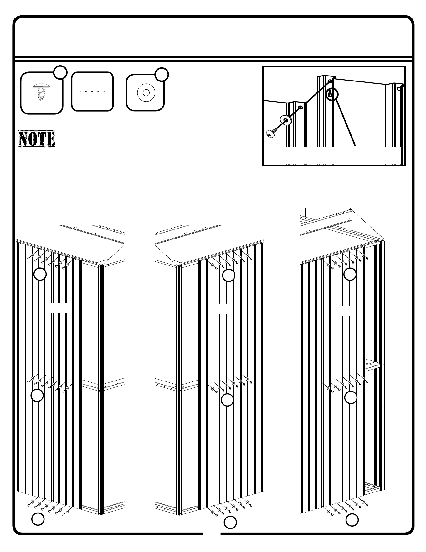
Continue installing panels up to each of the corners
except by the door.
66646
W
(x54)
Painted screws are to be used on painted parts
only. Make sure painted screws match wall color.
*When overlapping panels, make sure
arrow is towards the top and covered up
66611
WS
(x54)
3
2
1
11157
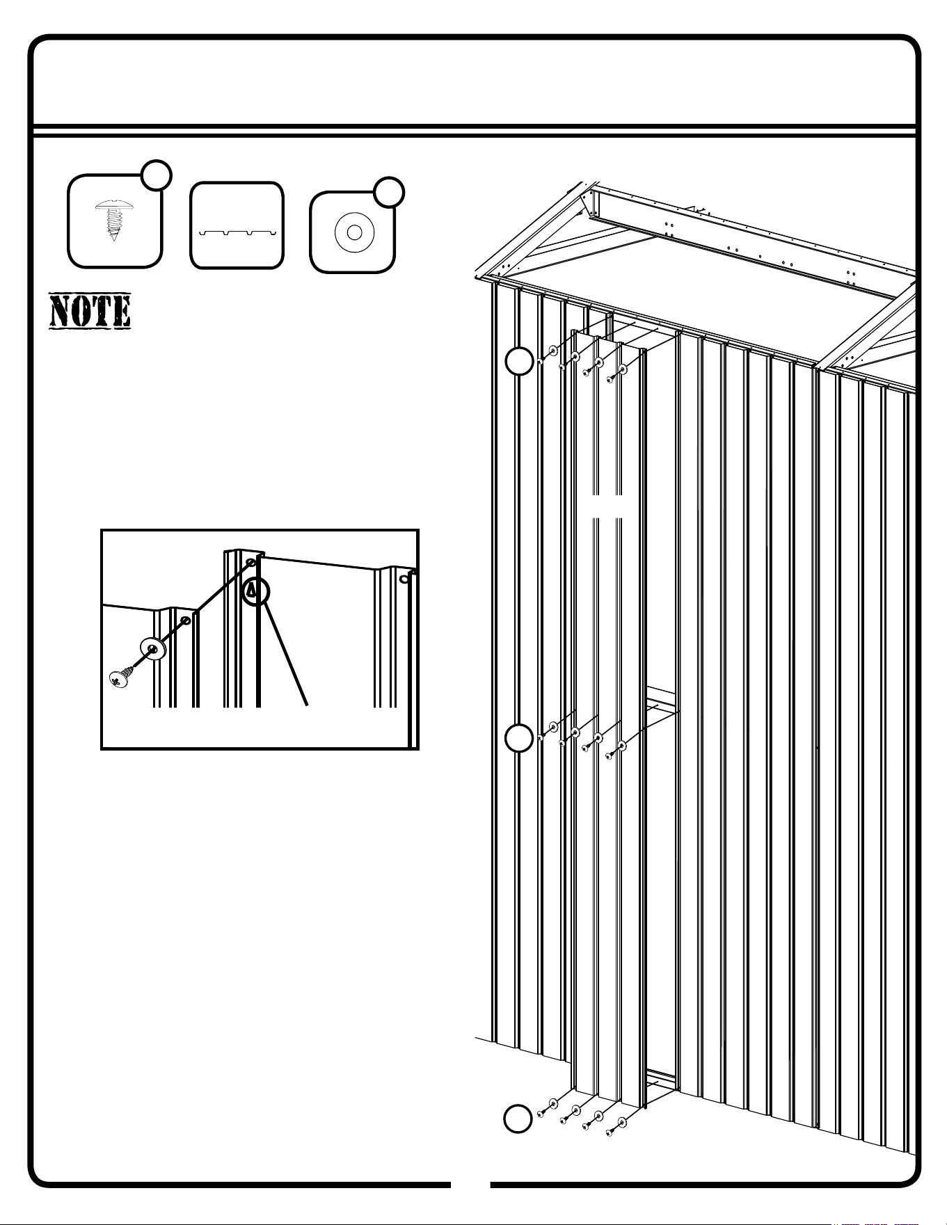
Step 12C
50
50GW
1
2
3
11166
Install Panels to cover each of
the gaps except around door
11166
(x2)
12x15+ Only
66646
W
(x24)
*When overlapping panels, make sure
arrow is towards the top and covered up
Painted screws are to be used on
painted parts only. Make sure painted
screws match wall color.
66611
WS
(x24)
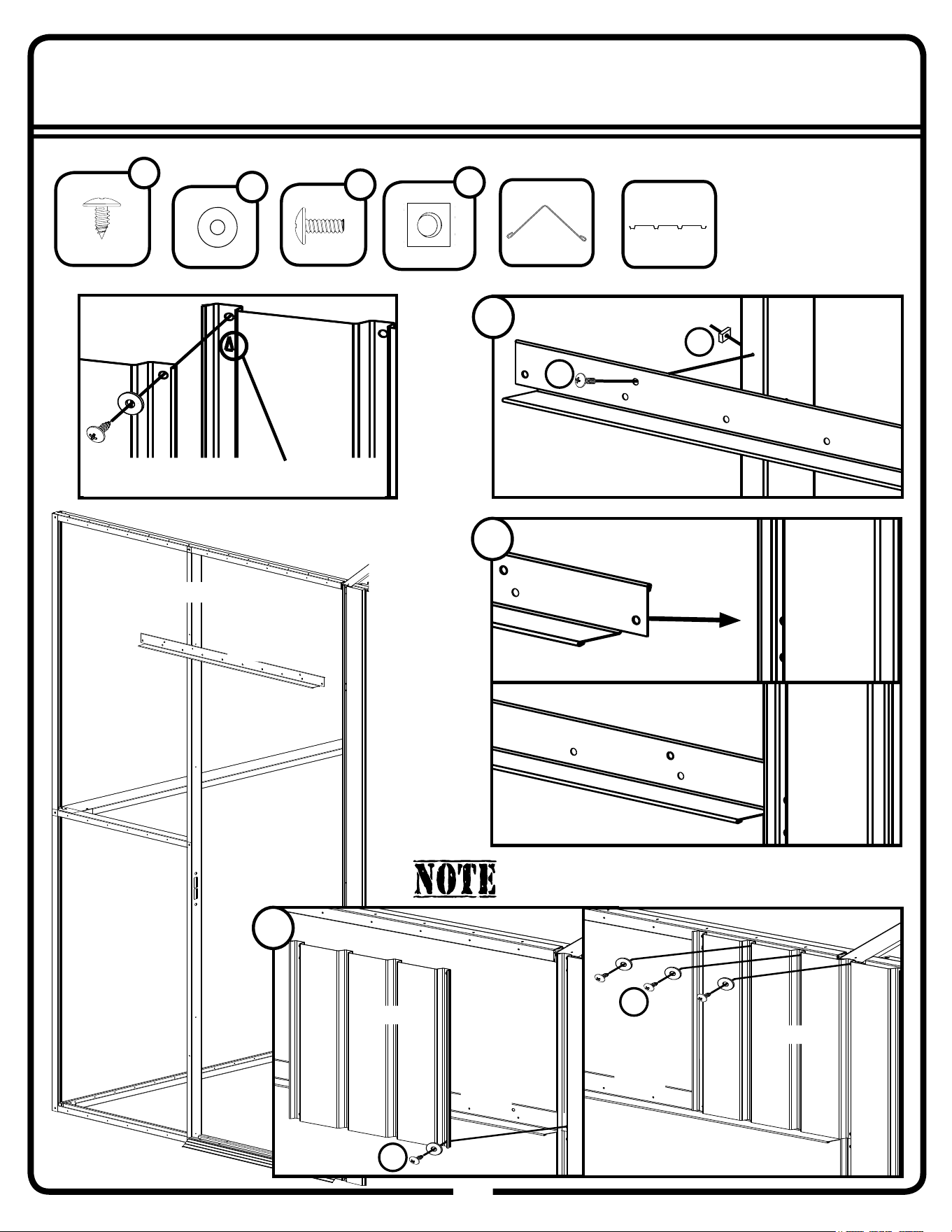
Step 13A
51
51GW
11207
(x1)
11181
(x1)
1
2
3
11181
11181
11207
11181
11181
11181
11181
11207
BB
N
WS
66646
W
(x4)
*When overlapping panels, make sure
arrow is towards the top and covered up
WS
Door Option A shown
Painted screws are to be used on painted parts only.
Make sure painted screws match wall color.
66611
WS
(x4)
65943
BB
(x1)
65106
N
(x1)
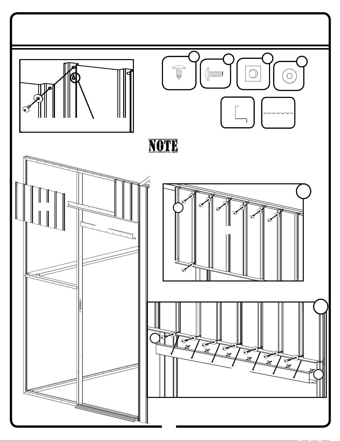
Step 13B
52
52GW
11170
(x1)
WS
11291
(x1)
11170
11291
11170
66646
W
(x14)
*When overlapping panels, make sure
arrow is towards the top and covered up
WB
N
11291
Painted fasteners are to be used on painted parts only.
Make sure painted fasteners match wall color.
1
2
66611
WS
(x7)
65943
WB
(x7)
65106
N
(x7)
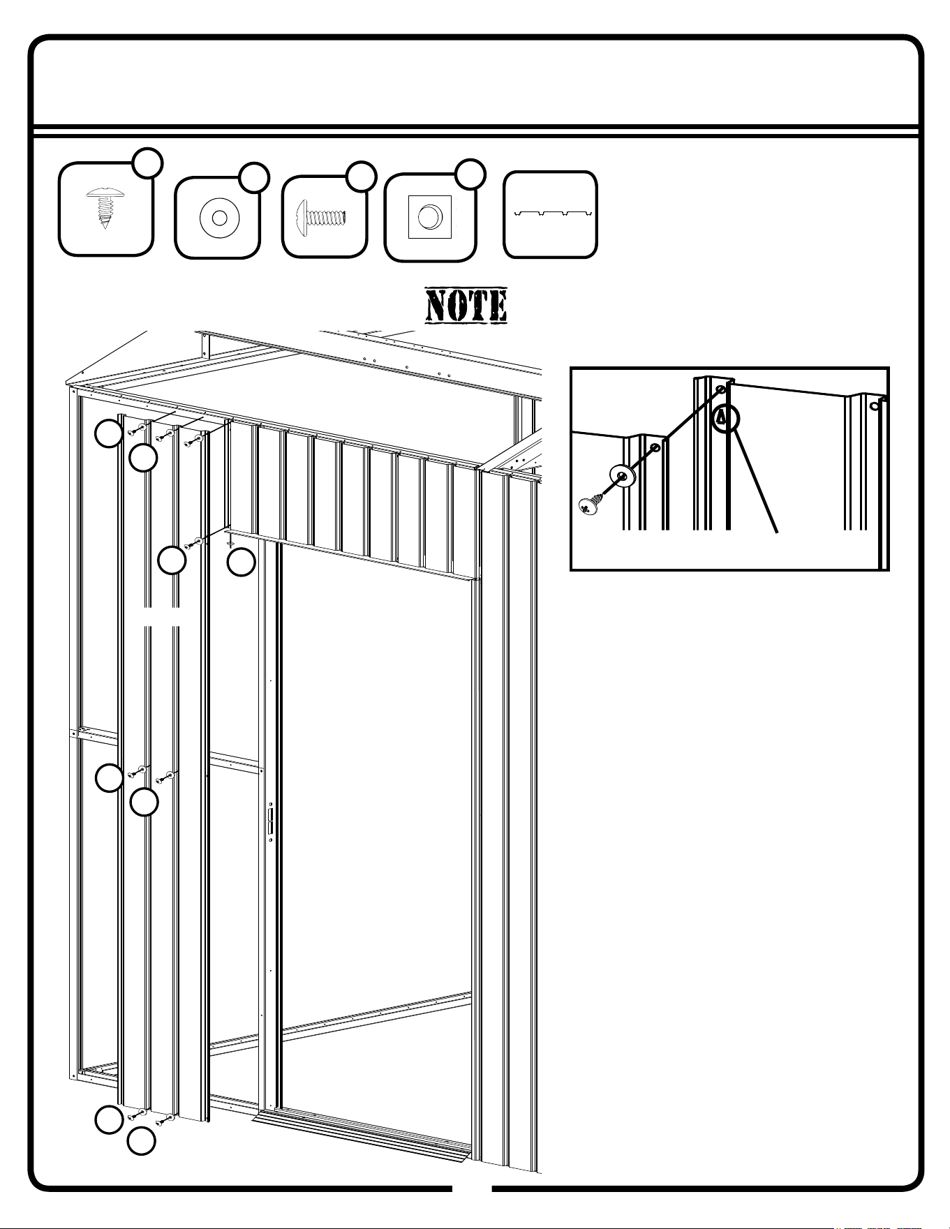
Step 13C
53
53GW
11160
(x1)
66646
W
(x8)
1
2
3
*When overlapping panels, make sure
arrow is towards the top and covered up
Painted fasteners are to be used on painted parts only.
Make sure painted fasteners match wall color.
WS
WS
WS
WB
N
11160
66611
WS
(x7)
65943
WB
(x1)
65106
N
(x1)
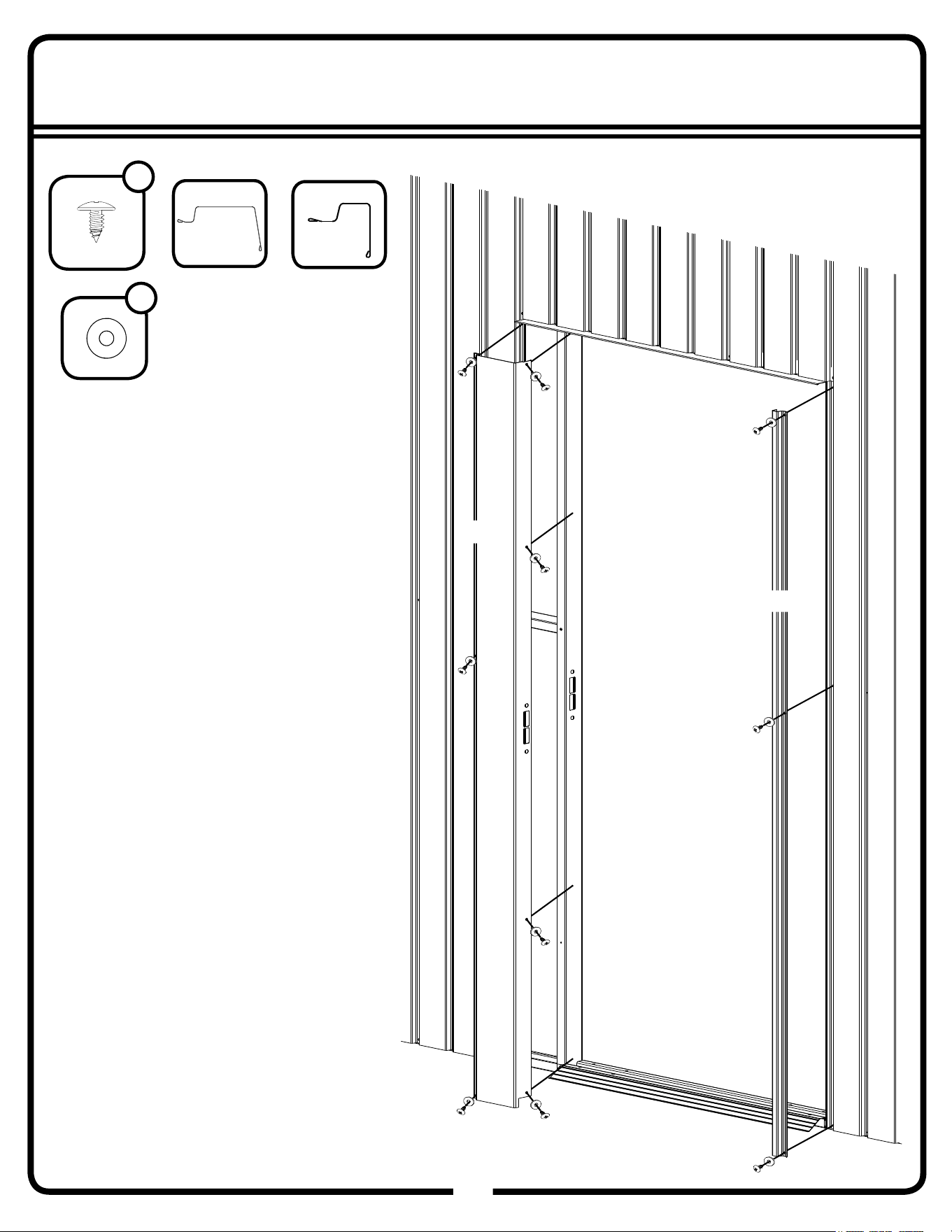
Step 13D
54
54GW
11182
(x1)
11182
80153
(x1)
80153
66646
W
(x10)
66611
WS
(x10)
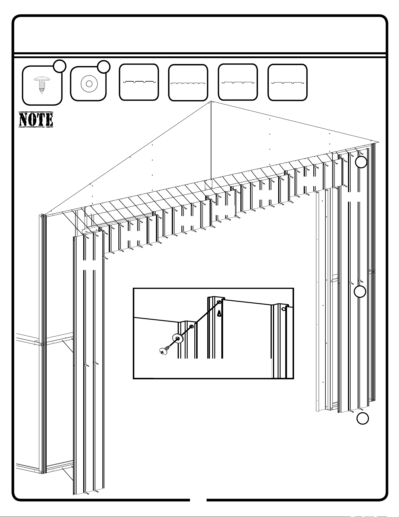
Step 14
55
55GW
11173
(x1)
11172
(x4)
11172
11172
11172
11172
11173
*When overlapping panels,
make sure arrow is covered up
80161
11169
80161
(x1)
11169
(x1)
66646
W
(x68)
3
2
1
Painted fasteners are to be used
on painted parts only. Make sure
painted fasteners match wall color.
66611
WS
(x68)
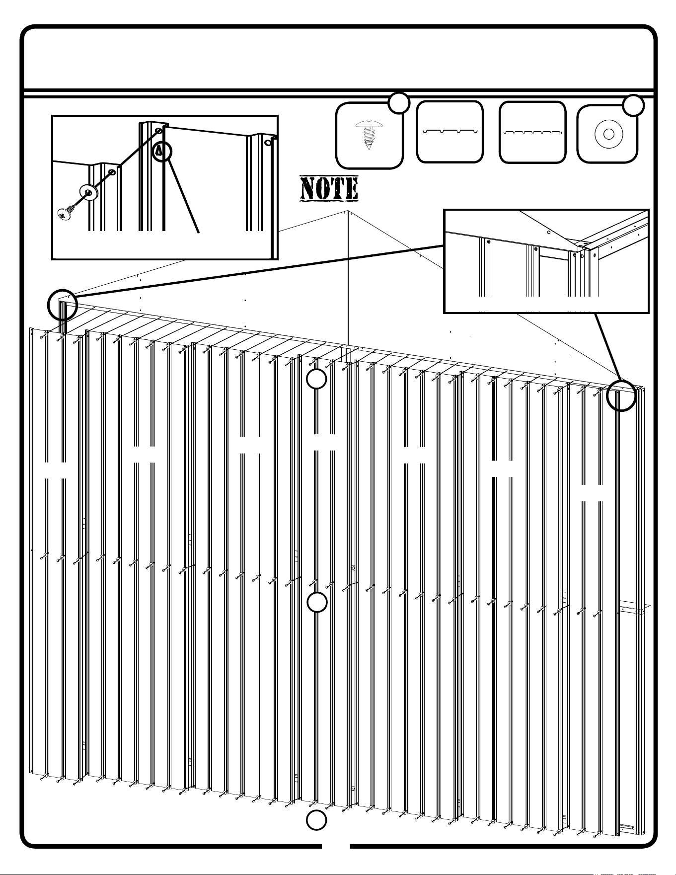
Step 15
56
56GW
Rear
11166
(x3)
11157
(x4)
11166
11166
11157
11157
11157
11157
11166
66646
W
(x96)
3
2
1
*Panels don’t go all the way to corner
*When overlapping panels, make sure
arrow is towards the top and covered up
Painted fasteners are to be used on painted parts only.
Make sure painted fasteners match wall color.
66611
WS
(x96)
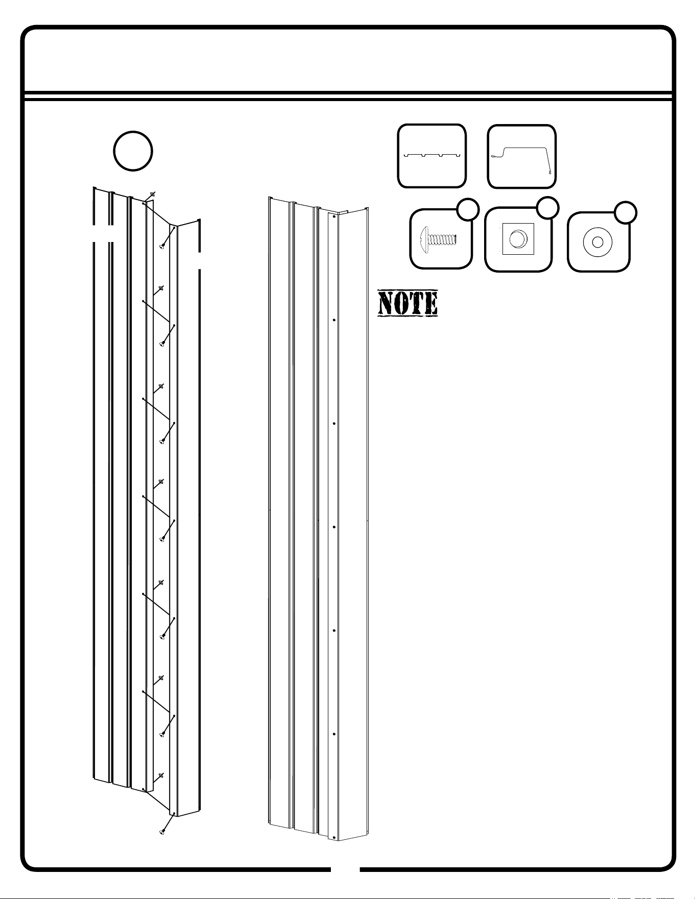
Step 16A
57
57GW
11168
(x4)
11153
(x4)
11153
11168
66646
W
(x28)
Painted fasteners are to be used on
painted parts only. Make sure painted
fasteners match wall color.
x4
65943
WB
(x28)
65106
N
(x28)
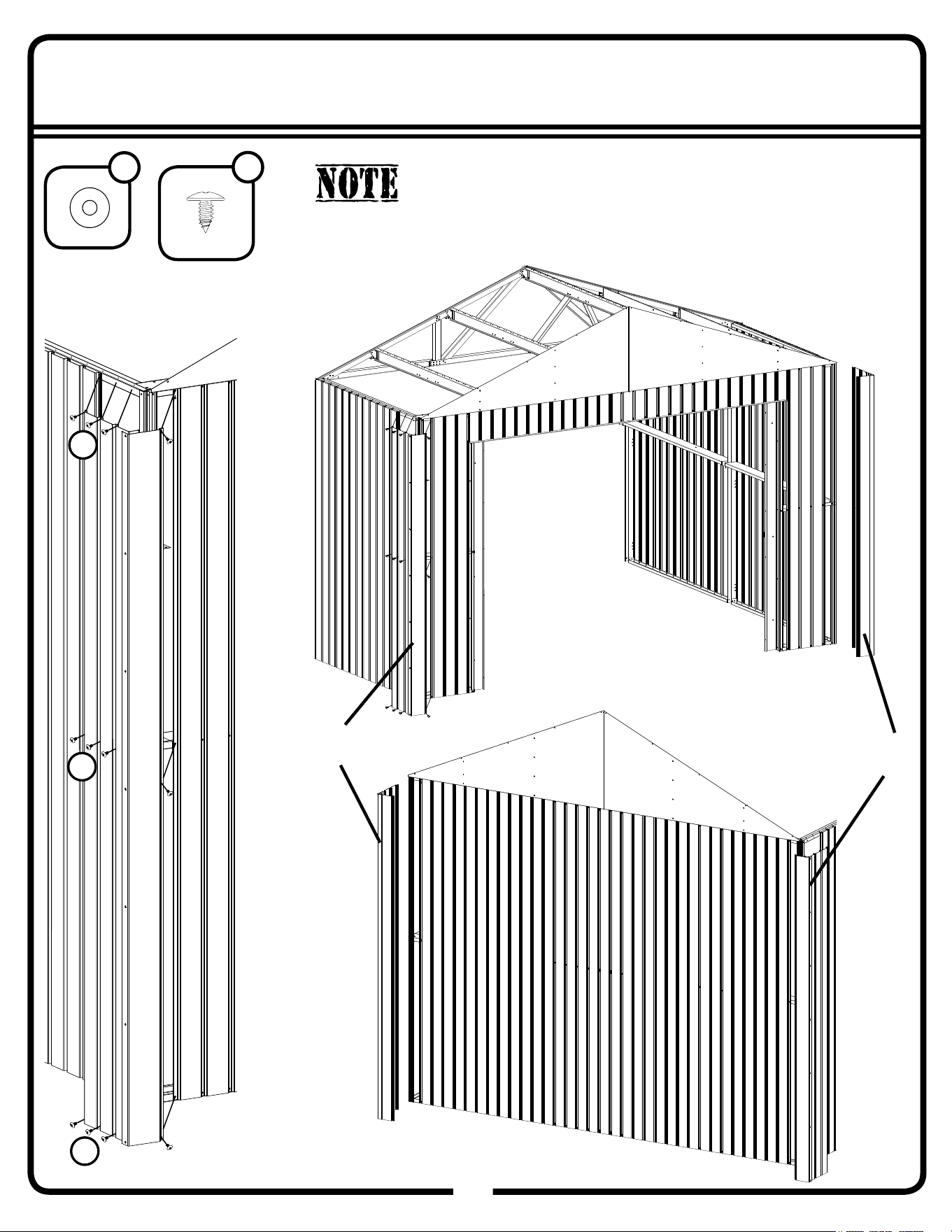
Step 16B
58
58GW
Install the corner panel subassemblies
to each of the 4 corners.
Front
Rear
Subassembly
from page 57
Subassembly
from page 57
66646
W
(x48)
1
2
3
Painted fasteners are to be used on painted parts
only. Make sure painted fasteners match wall color.
66611
WS
(x48)
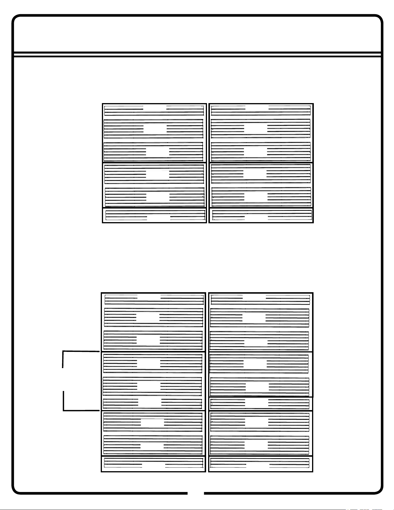
Roof Panel Orientation
59
59GW
80151
80151
11174
11174
11174
11174
11174
11174
11174
11174
11178
11178
11178
11178
80151
80151
11174
11174
11174
11175
11174
11174
11174
11174
11175
11174
11174
11174
11174
11174
Front
Front
Rear
Rear
12x10
12x15
Extension
Kit(s)
17A
17B
17D
18A
18D
18A
18C
18D
18B
17A
17B
17C
17D
18E
18E
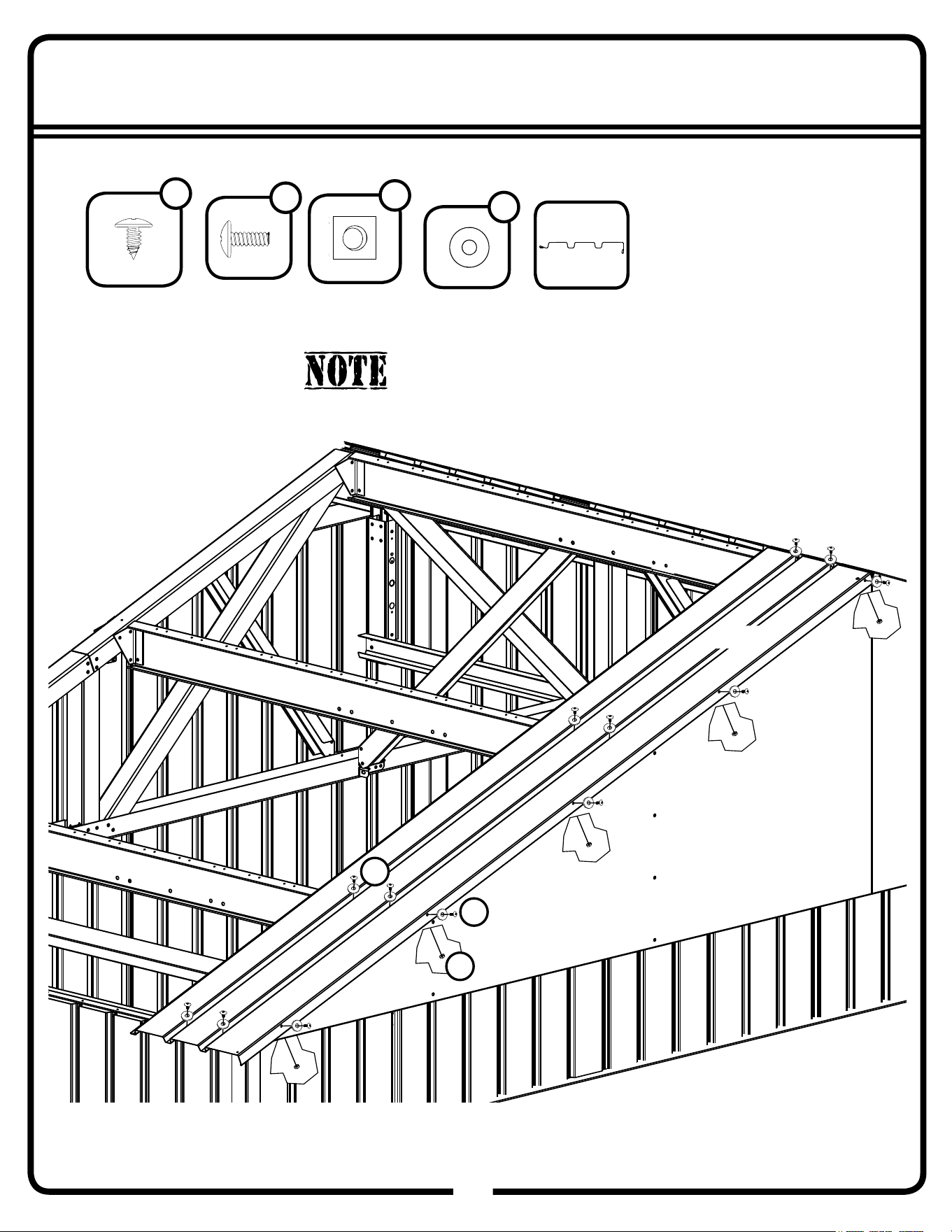
Step 17A
60
60GW
11178
11178
(x1)
Front
66646
W
(x13)
Use painted fasteners that match roof panel color
RB
RS
N
66611
RS
(x8)
65943
RB
(x5)
65106
N
(x5)
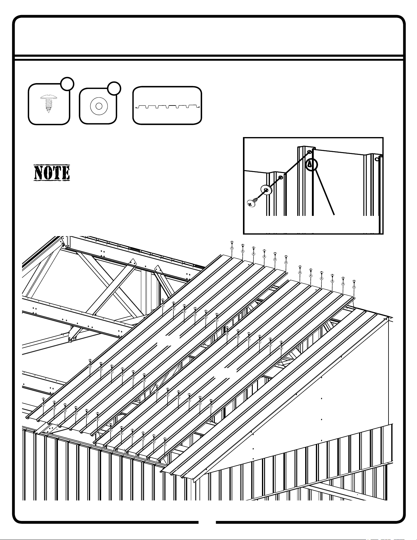
Step 17B
61
61GW
11174
(x2)
11174
11174
Front
*When overlapping panels, make sure
arrow is towards the top and covered up
66646
W
(x48)
Use painted fasteners that match roof panel color
66611
RS
(x48)
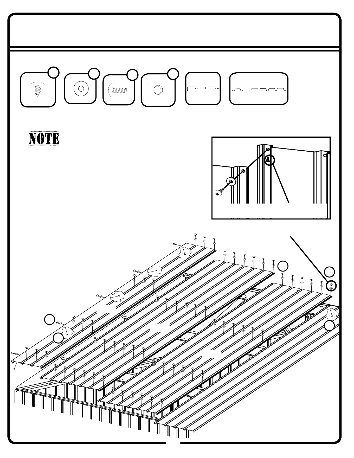
Step 17C
62
62GW
11174
11174
11175
11174
(x2)
11175
(x1)
66646
W
(x60)
*Use bolt for top of truss
*
12x15+
Extension x1
Install panels in this order for every 5’ extension section
Use painted fasteners that match
roof panel color
*When overlapping panels, make sure
arrow is towards the top and covered up
RS
RB
*Lubricate screws
to aid assembly
N
66611
RS
(x59)
65943
RB
(x1)
65106
N
(x1)
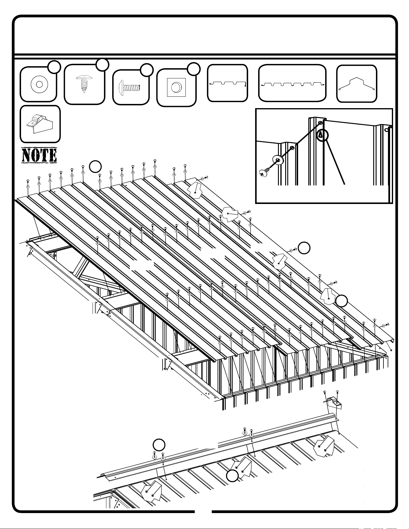
Step 17D
63
63GW
11174
11174
Rear
80151
(x1)
80151
11174
(x2)
RB
*
RS
66646
W
(x65)
Use painted fasteners that match
roof panel color
*When overlapping panels, make sure
arrow is towards the top and covered up
RB
*Use bolt for top of truss
N
N
66611
RS
(x59)
65943
RB
(x6)
65106
N
(x6)
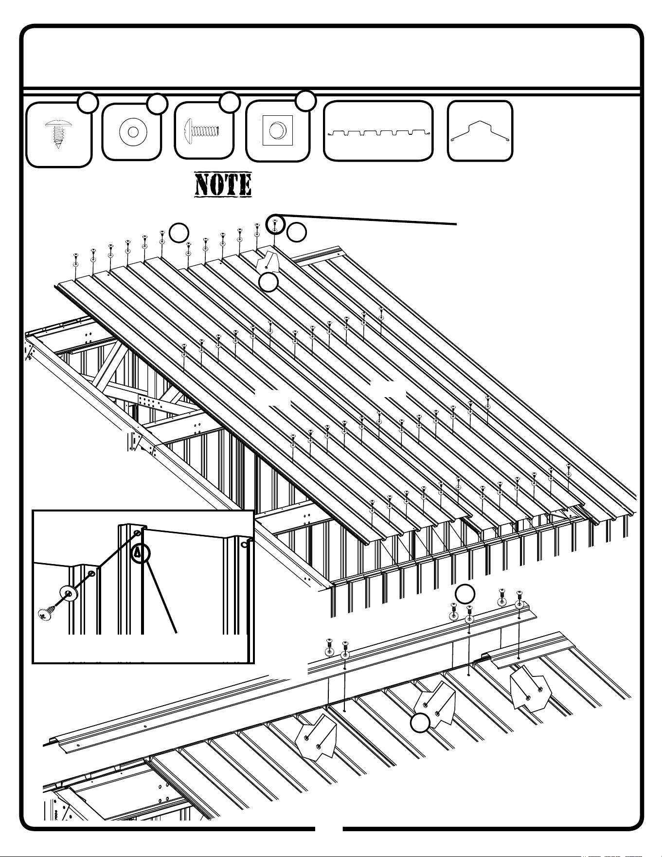
Step 18A
64
64GW
11178
Rear
66646
W
(x65)
Use painted fasteners that match roof panel color
RB
RS
11178
(x1)
11174
(x2)
11174
11174
11202
11202
(x1)
*When overlapping panels, make sure
arrow is towards the top and covered up
30003
(x1)
30003
RB
N
N
66611
RS
(x56)
65943
RB
(x11)
65106
N
(x11)
Step 18B
65
65GW
Rear
12x15+
Extension x1
11205
11174
11174
11174
(x2)
66646
W
(x54)
*Use bolt for
top of truss
RB
*
RS
RB
11205
(x1)
*When overlapping panels, make sure
arrow is towards the top and covered up
*Lubricate screws
to aid assembly
Use painted fasteners that match roof panel color
N
N
66611
RS
(x47)
65943
RB
(x7)
65106
N
(x7)
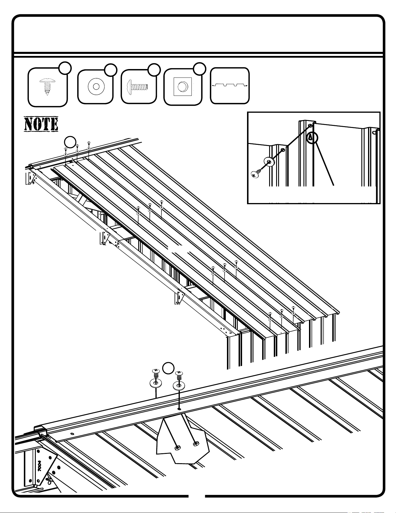
Step 18C
66
66GW
66646
W
(x14)
Use painted fasteners that match roof panel color
11175
*When overlapping panels, make sure
arrow is towards the top and covered up
RB
RS
11175
(x1)
12x15+
Extension x1
66611
RS
(x12)
65943
RB
(x2)
65106
N
(x2)
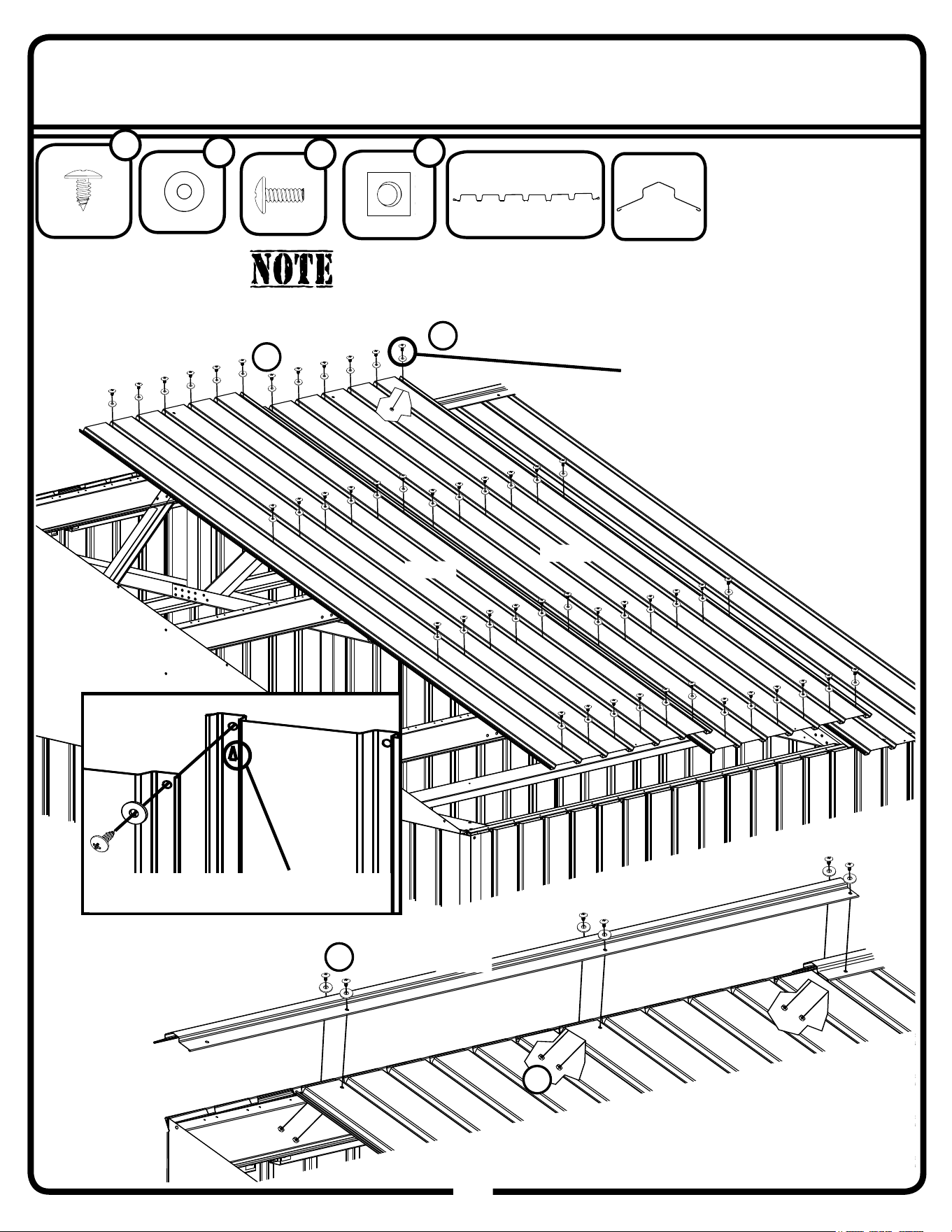
Step 18D
67
67GW
Front
66646
W
(x54)
Use painted fasteners that
match roof panel color
RS
RB
11174
(x2)
11174
11202
11202
(x1)
*When overlapping panels, make sure
arrow is towards the top and covered up
11174
*Use bolt for top of truss
RB
*
*Lubricate screws
to aid assembly
N
66611
RS
(x47)
65943
RB
(x7)
65106
N
(x7)
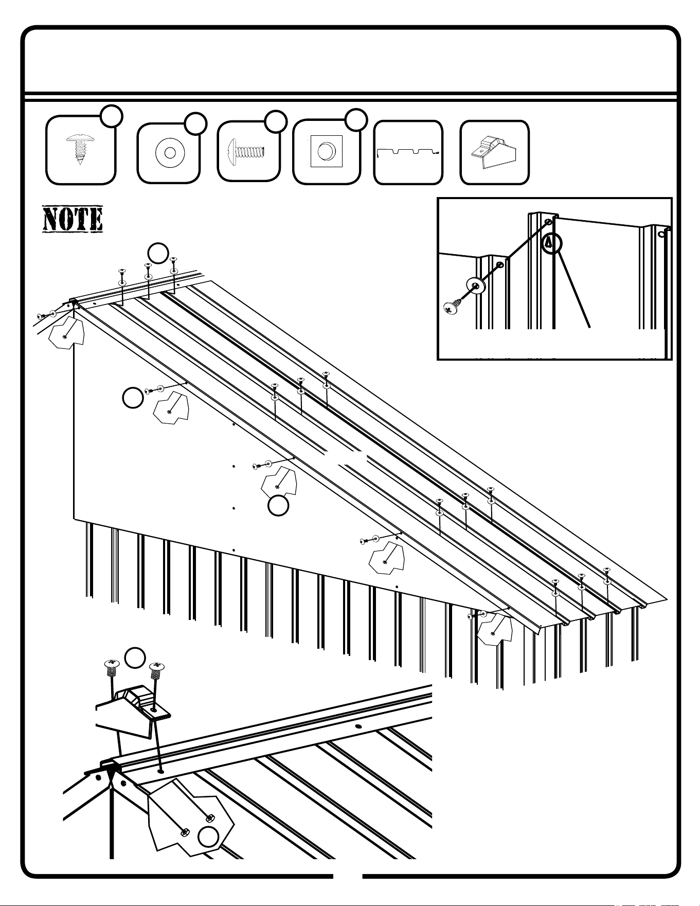
Step 18E
68
68GW
Front
66646
W
(x17)
Use painted fasteners that match roof panel color
RS
RB
80151
*When overlapping panels, make sure
arrow is towards the top and covered up
80151
(x1)
RB
30003
30003
(x1)
N
N
66611
RS
(x12)
65943
RB
(x7)
65106
N
(x7)
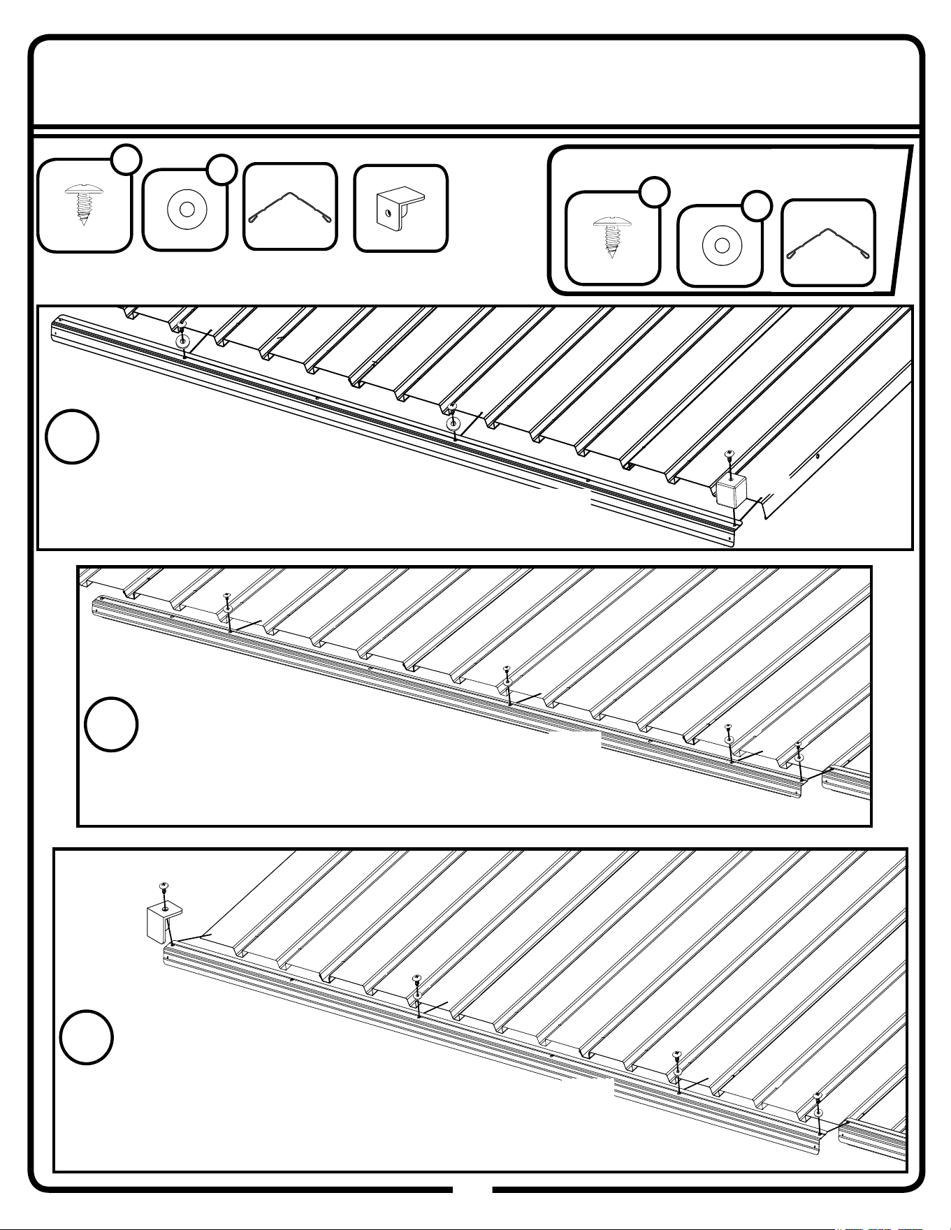
Step 19
69
69GW
11204
(x4)
11204
Install a 11203 roof trim for every 5’ extension section
11203
12x15+
11203
(x2)
Install roof trim on both sides of the shed
11204
Rear
Front
66646
W
(x10)
Extension x1
66646
W
(x8)
60H
60H
60H
(x4)
x2
x2
x2
66611
RS
(x8)
66611
RS
(x14)
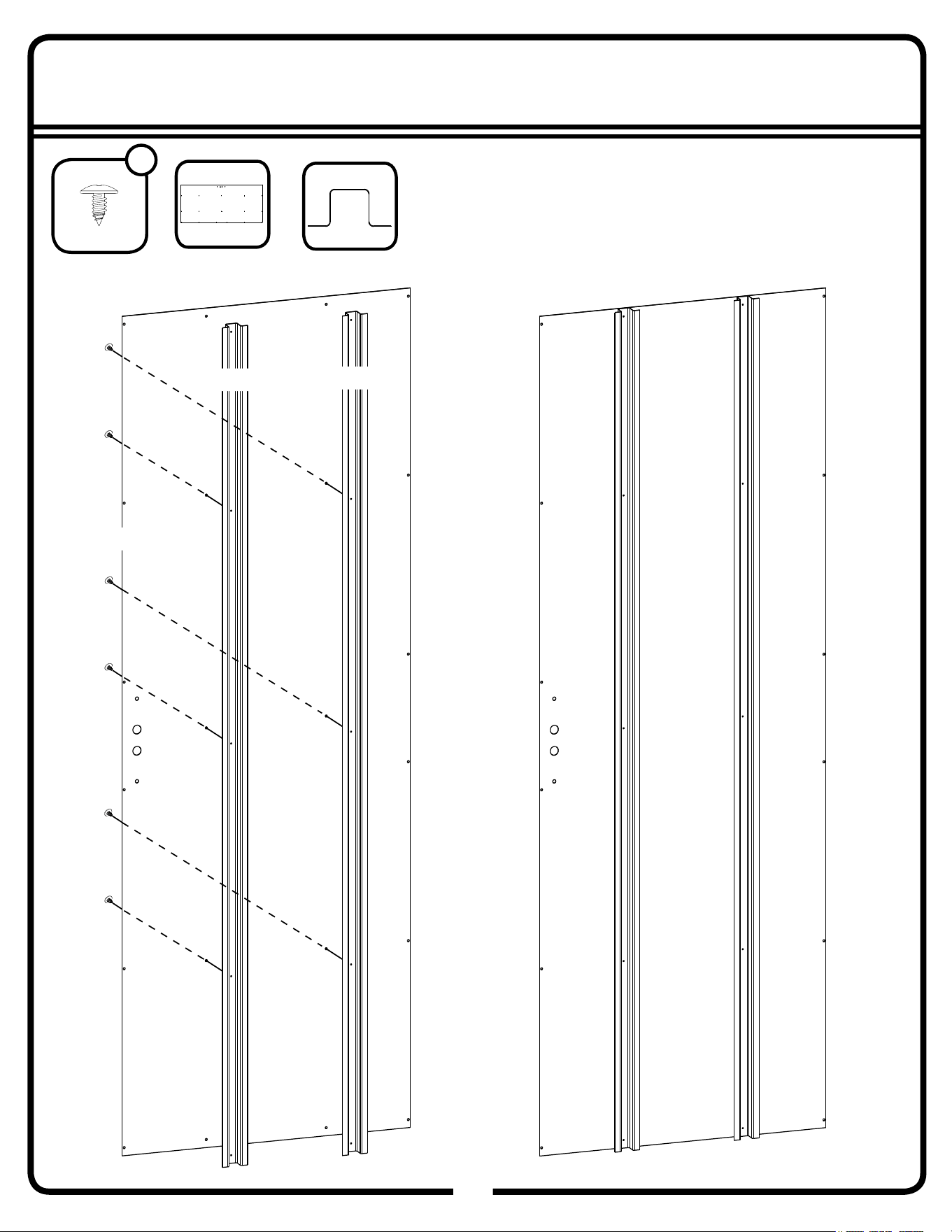
Step 20A
70
70GW
11195
(x2)
11200
11200
(x1)
11195
11195
66611
BS
(x6)
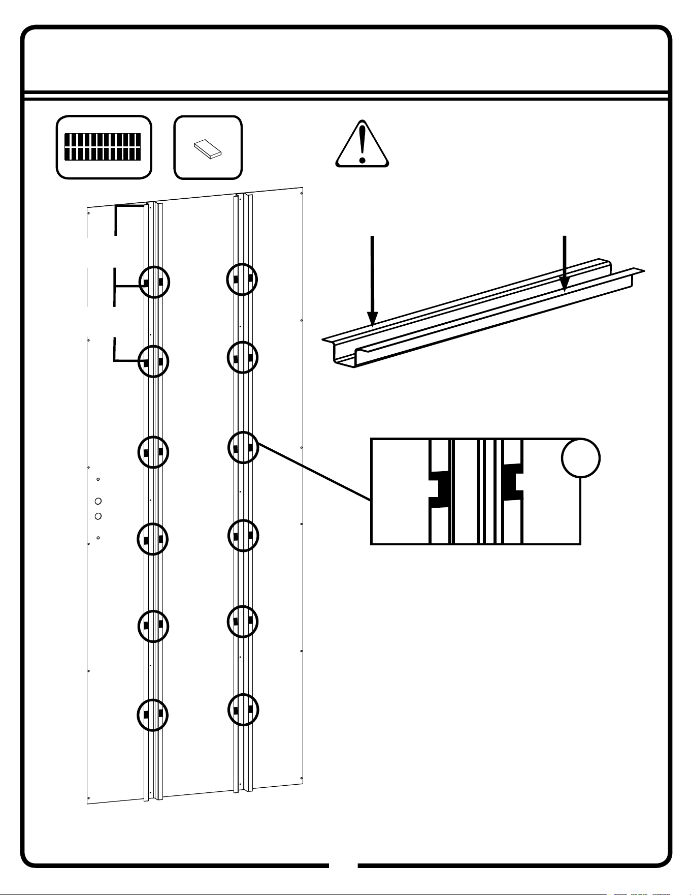
Step 20B
71
71GW
Press tape fi rmly along the door braces approximately
1
1” (27,9 cm) apart. DO NOT peel the backing off at this
time.
Tape
Tape
x12
Once tape sticks to a surface it
CAN NOT be removed.
Wipe the legs of 11195 thoroughly with alcohol
pads (30018) before applying tape (30005)
30005
(x1)
30018
(x2)
Approximately 11”
(27,9 cm)
Approximately 11”
(27,9 cm)
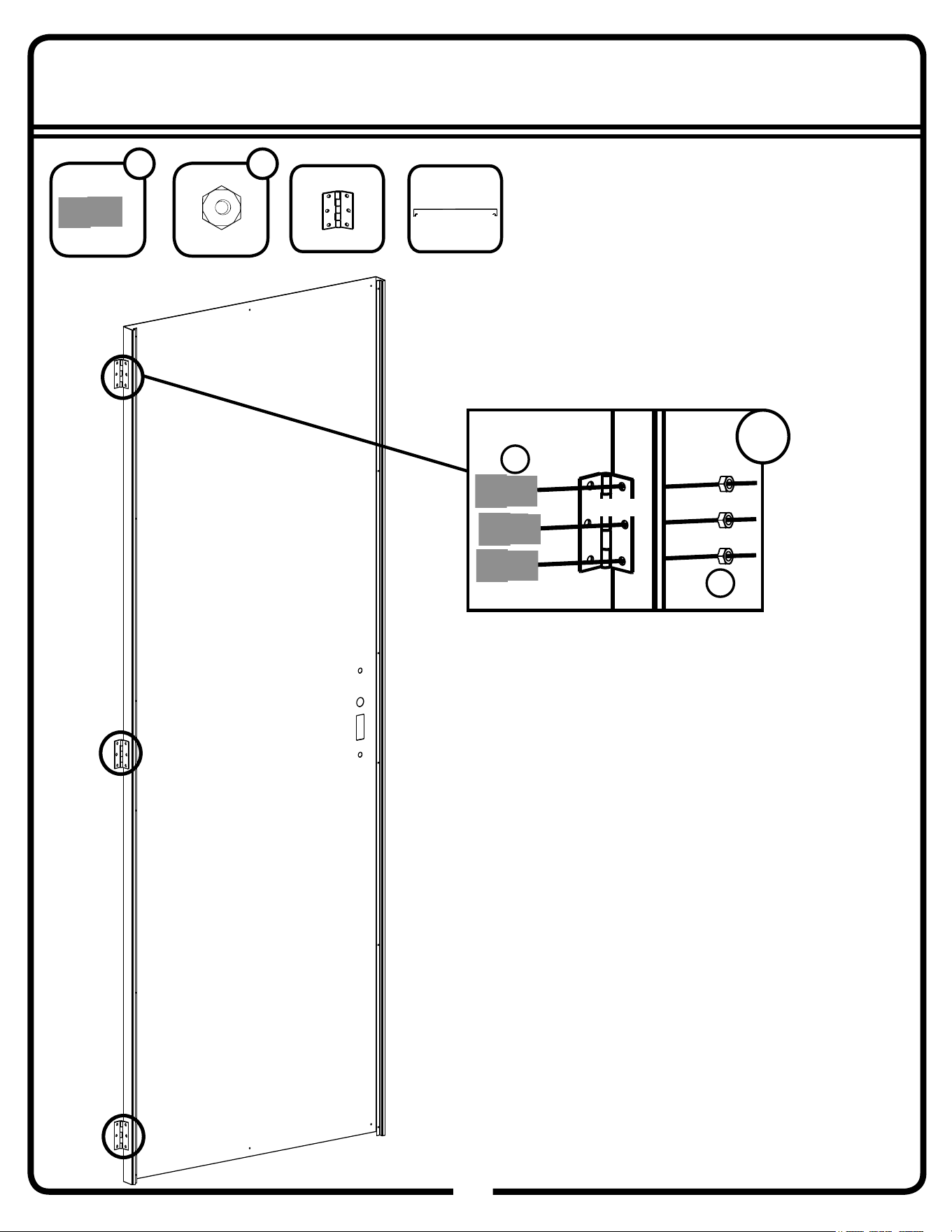
Step 20C
72
72GW
66609
x3
FB
66783
FB
(x9)
65103
HN
(x9)
66609
(x3)
11193
(x1)
HN
11193
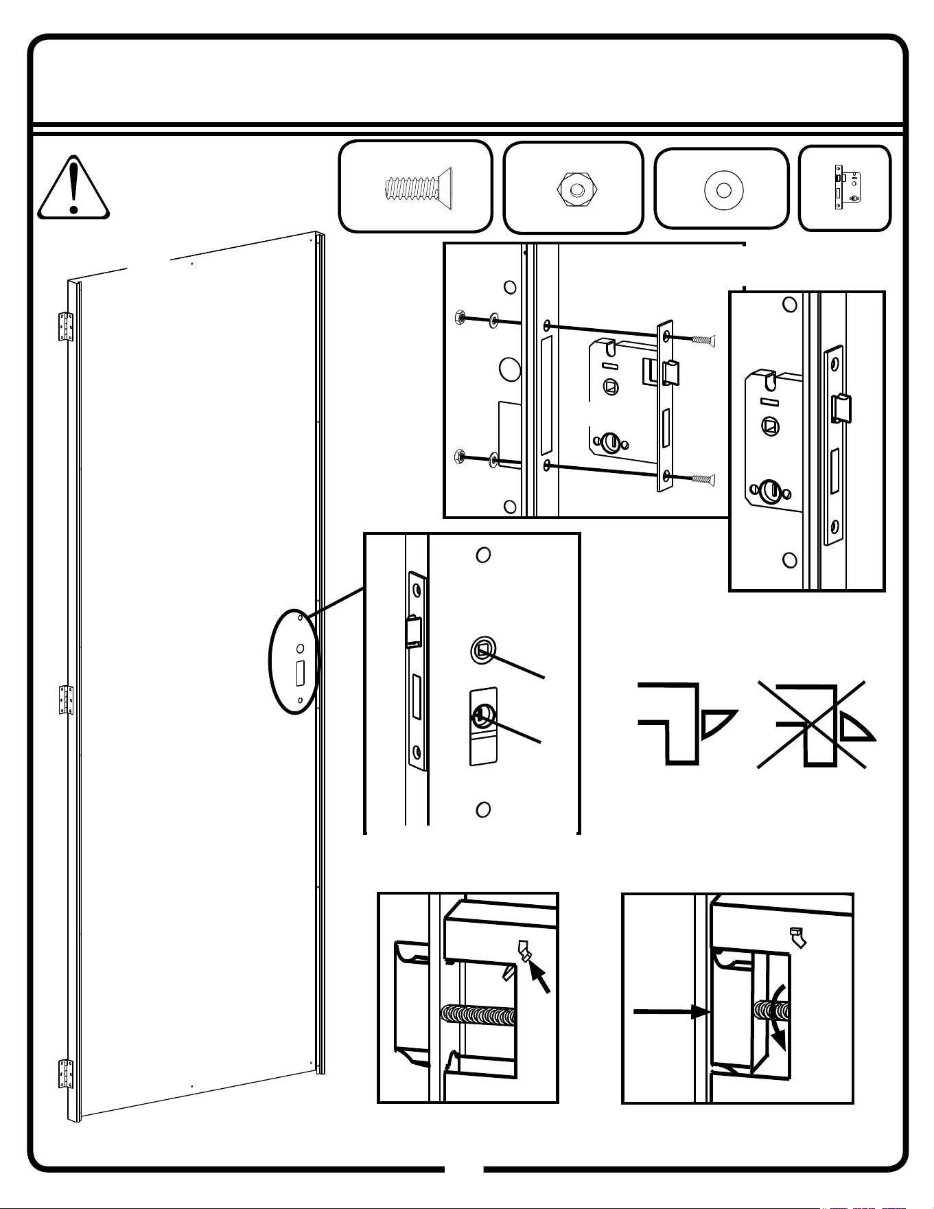
Step 20D
73
73GW
M5x10 Screw
(x2)
M5 Hex Nut
(x2)
Make sure holes line up
Mortise
(x1)
Make sure holes are in the
orientation shown
M5 Washer
(x2)
Mortise
Use hardware supplied
with handle assembly
box for this page
Top
If door latch is in wrong
orientation, push tab up
Push latch in and rotate
to correct orientation
Correct
Orientation
Incorrect
Orientation
Door Latch Orientation
Top View
Outside Door
Outside Door
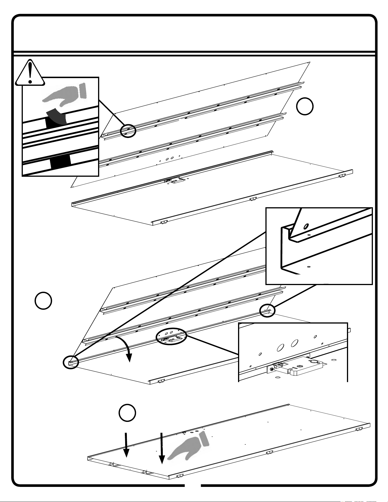
Step 20E
74
74GW
1
2
3
Lay the front panel on a fl at
surface. Using at least 2
people, place the edge of the
back panel on the edge of the
front panel with the mortise
Peel off the backs of the tape before proceeding.
Once tape sticks to a surface it CAN NOT be removed.
From Step 20B
From Step 20D
Carefully lower the
back panel down
so that the tape
makes contact
with the front
Make sure holes line up with mortise
Make sure corner holes line up
Press down fi rmly
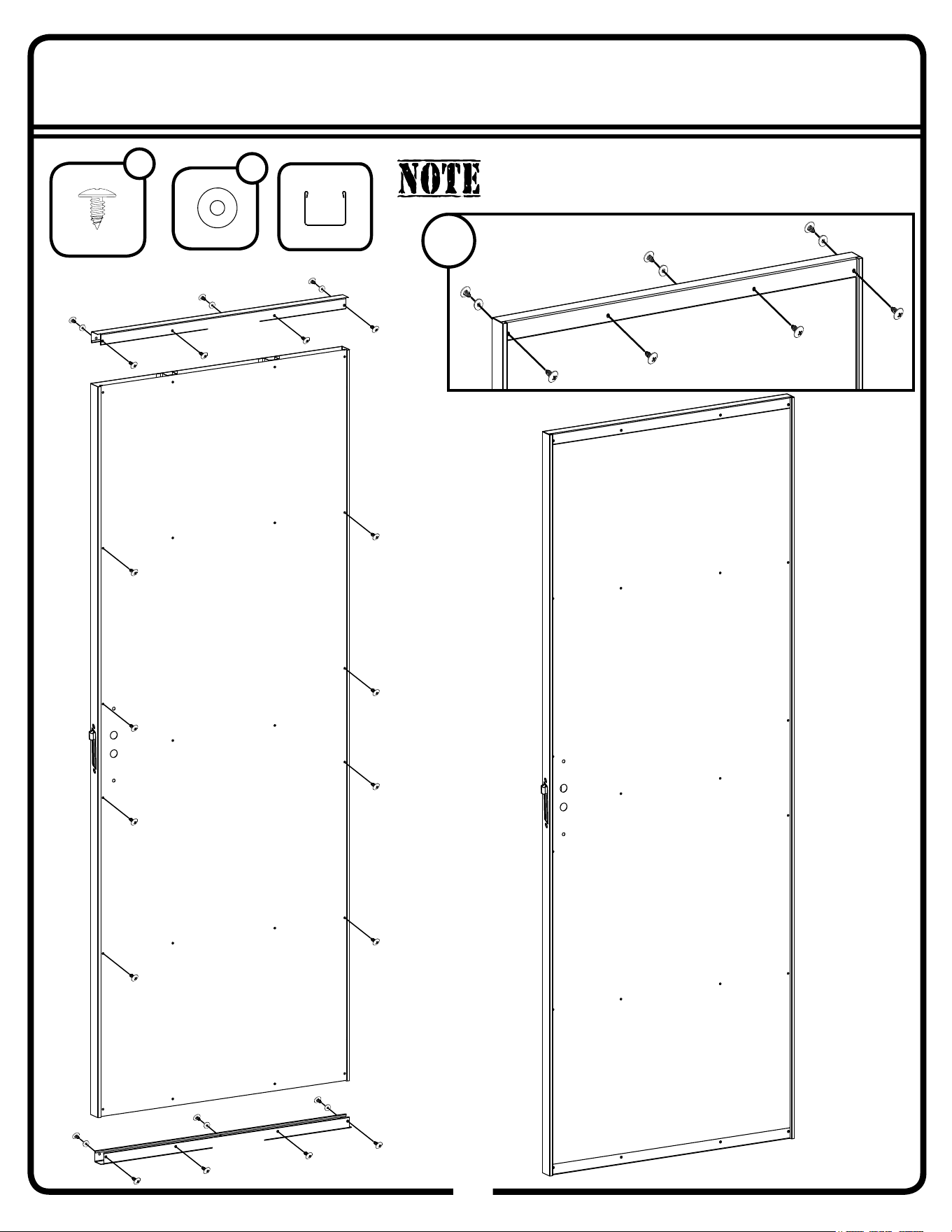
Step 20F
75
75GW
11196
(x2)
11196
11196
66646
W
(x6)
x2
*Washers on outside only
Use painted fasteners that match wall color
66611
WS
(x22)
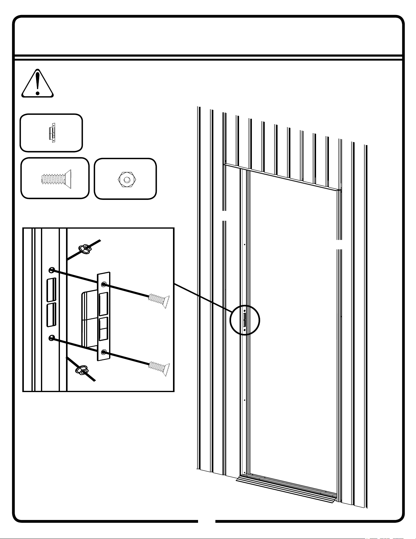
Step 21A
76
76GW
11182
Strike Plate
(x1)
80153
Use hardware supplied
with handle assembly
box for this page
M5x10 Screw
(x2)
M5 Hex Nut
(x2)
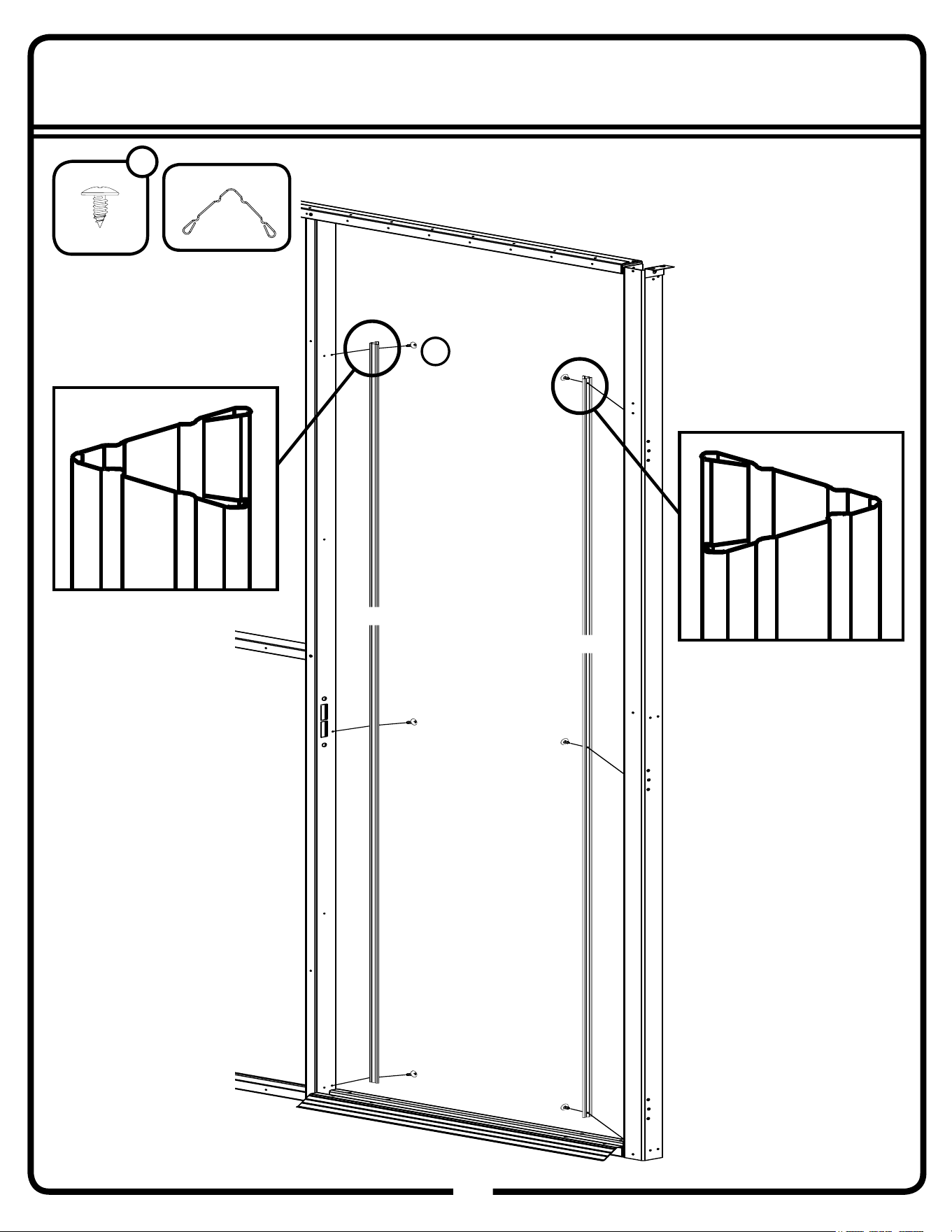
Step 21B
77
77GW
11177
BS
11177
11177
(x2)
66611
BS
(x6)
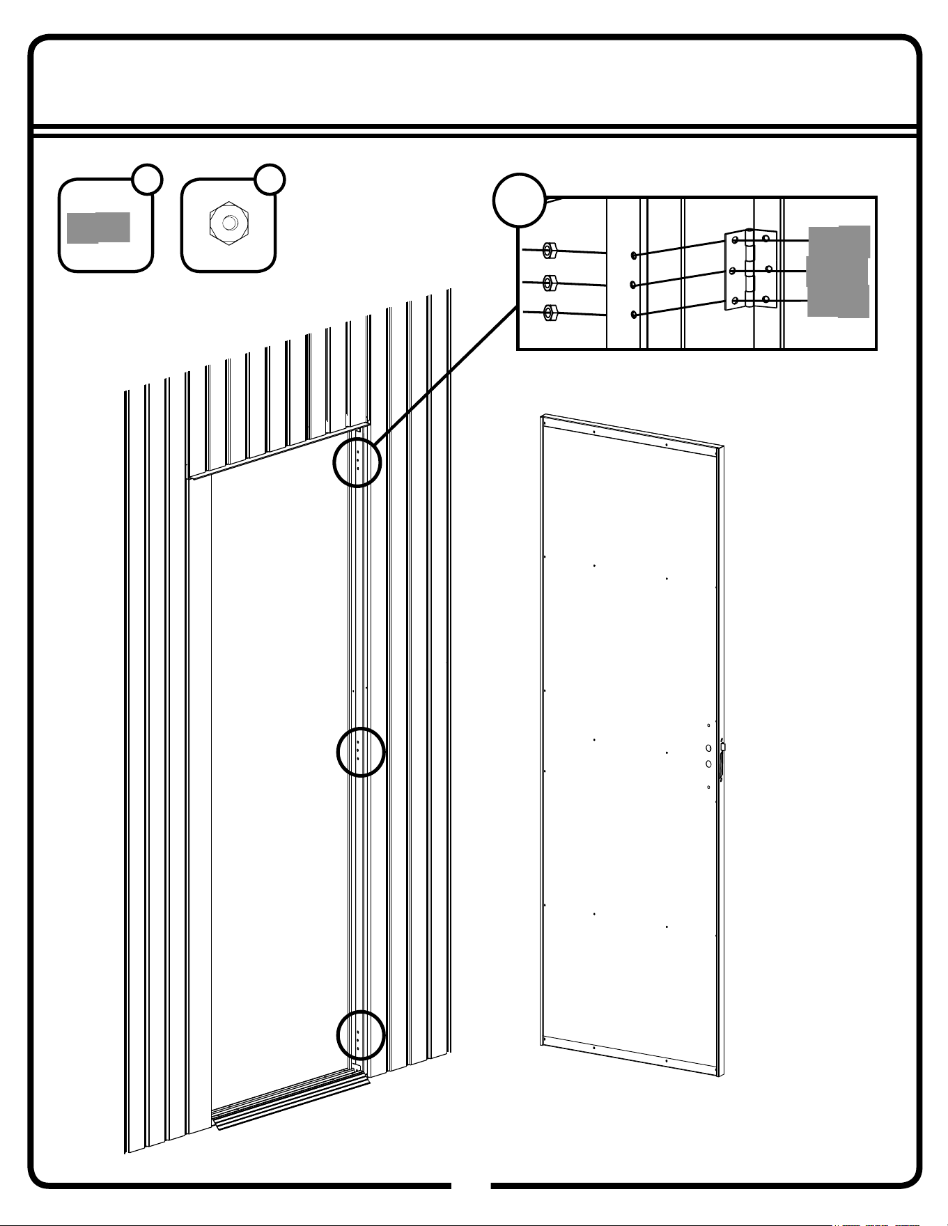
Step 21C
78
78GW
x3
66783
FB
(x9)
65103
HN
(x9)
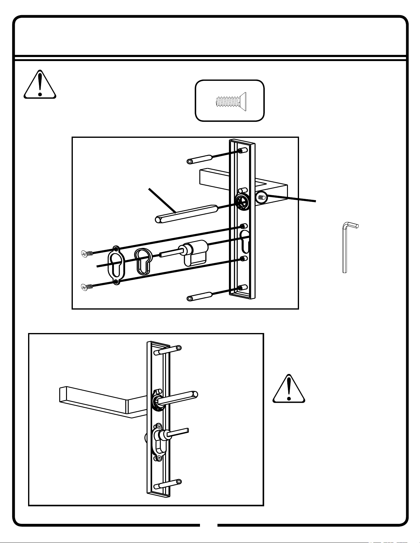
Step 22A
79
79GW
Use hardware supplied
with handle assembly
box for this page
Use Allen wrench
to tighten set screw
DO NOT lose keys.
Replacement keys
are not available
Post goes in all
the way
M4x5 Screw
(x2)
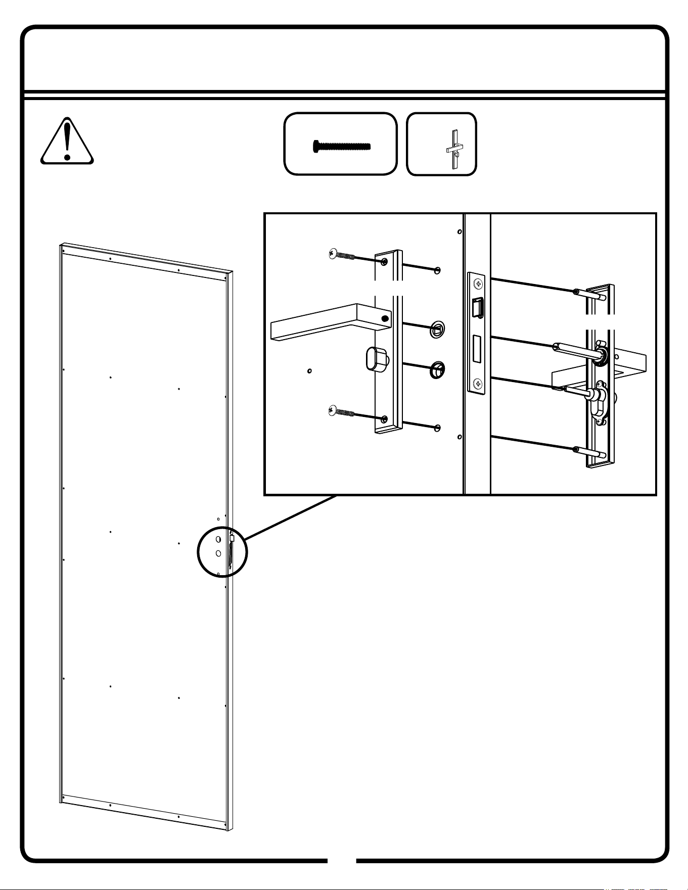
Step 22B
80
80GW
From Step 22A
Back Handle
Back
Handle
(x1)
M5x30 Screw
(x2)
Use hardware supplied
with handle assembly
box for this page
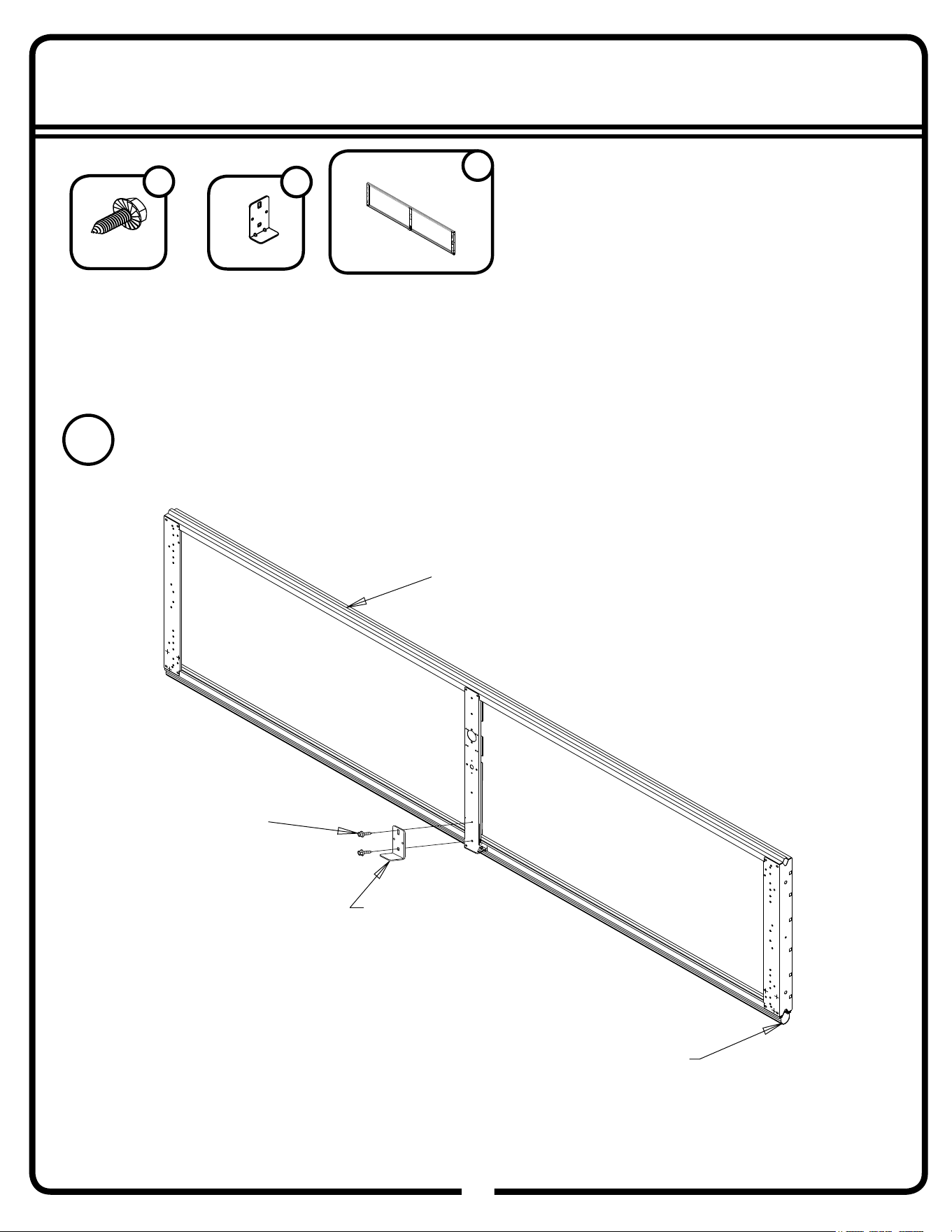
17
Step 23A: Bottom Panel
81GW
Inside Step Plate
1
81
Use screws to attach the Inside Step Plate to the Bottom Section as shown.
1
bottom section
Bottom Gripping Point/Step Plate Kit
1/4” Sheet Metal
Screw
2
Bottom Door Section
1
Look for the section with weather seal attached to it. This is the bottom section. Set it on table face down (the
face is the outside of the door).
bottom section
weather seal
1/4” sheet
metal screws
inside step plate
17
Step 23B: Bottom Panel
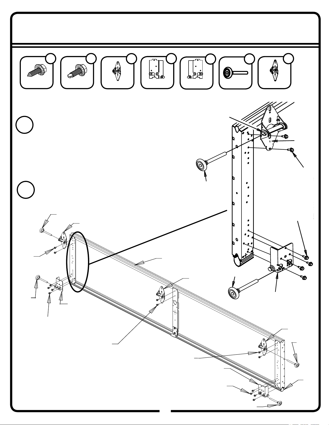
82GW
82
#1 End Hinge
Sections are attached to each other with hinges. Fasten
hinges
marked #1 to top of bottom section at each stile us-
ing (2) 1/4” sheet metal screws per hinge. Make sure that
the two slots are at top of hinge. This allows for adjustment
when you stack sections. Attach each bottom fi xture with (4)
red 1/4” sheet metal screws.
2
The door is held in the track with rollers. Insert rollers into
bottom fi xtures and end hinges.
3
1/4”
Sheet
Metal
Screws
Bottom
Fixture
Left
#1 Center
Hinge
#1 End
Hinge
Weather
Seal
Roller
Bottom Fixture
Right
Red 1/4”
Self Drilling Screws
Roller
Carrier
Hinge
Number
#1 End Hinge
2
Bottom Fixture
Right
1
Roller
4
#1 Center Hinge
1
1/4” Sheet Metal
Screw
6
1/4” Self Drilling
Screw (Red)
8
Roller
Roller
Roller
1/4” Sheet
Metal Screws
Red 1/4”
Self Drilling
Screws
1/4” Sheet
Metal Screws
Bottom Fixture
Left
1
1/4”
Sheet
Metal
Screws
Bottom
Section
Red 1/4”
Self Drilling
Screws
Roller
Roller
Bottom Fixture
Left
17
Step 24A: #2 Panel
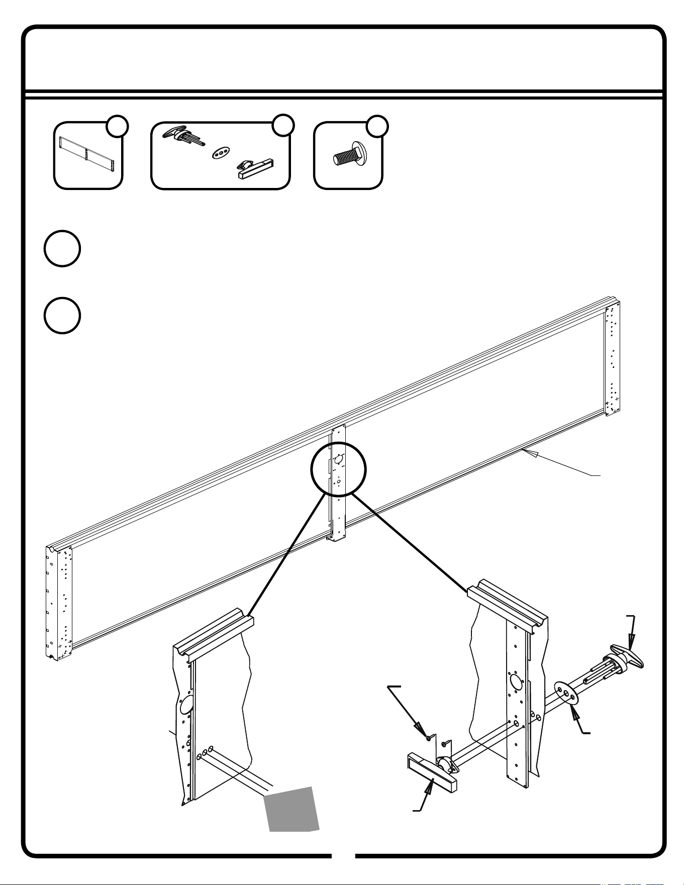
83GW
83
10-24 x 5/8”
bolt
lock/outside
handle
outside
handle plate
inside
handle
Drill three 1/2” holes into the section face. Drill
completely
through the section for the middle hole.
1
Install lock assembly in section.
2
#2 Door Section
1
Door Lock Assembly
1
10-24 x 5/8”
Bolt
2
#2 Section
1/2” drill
17
Step 24B: #2 Panel
84GW
84
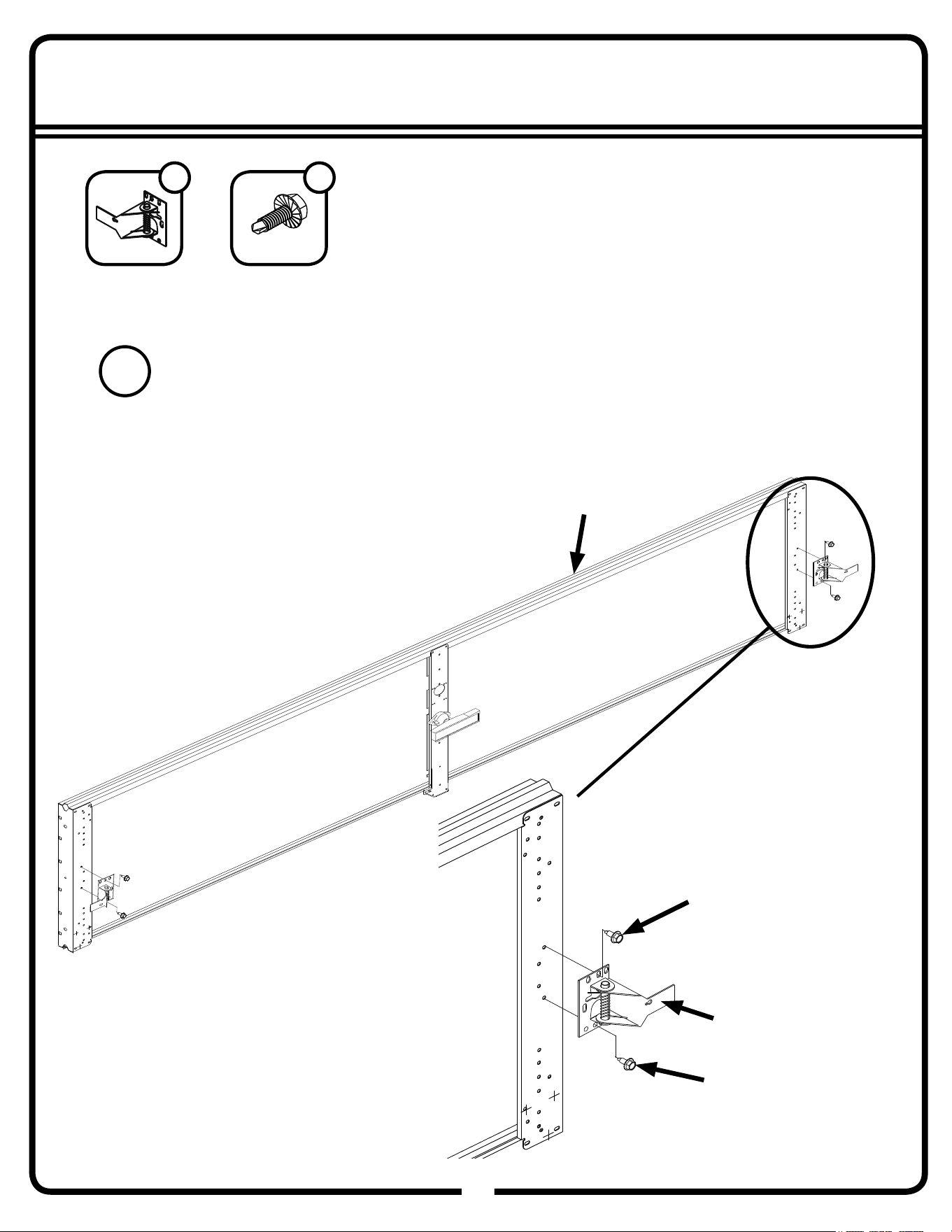
1/4” self drilling
screw
snap latch
Snap Latch
2
Attach a snap latch assembly to each end stile using two 1/4” self drilling screws.
3
1/4” self drilling
screw
1/4” Self Drilling
Screw
4
#2 Section
17
Roller
Carrier
Hinge
Number
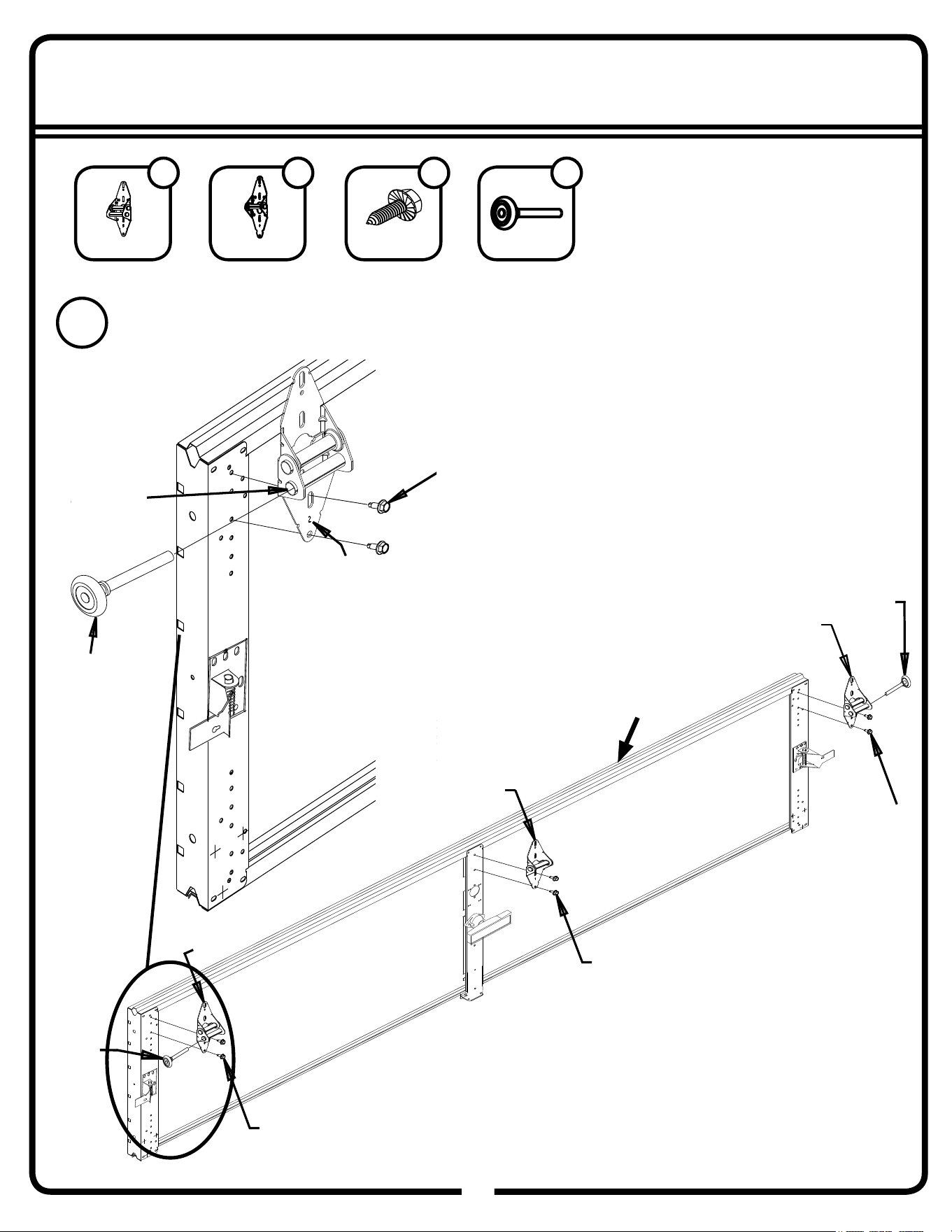
Step 24C: #2 Panel
85GW
85
#2 End Hinge
2
1/4” Sheet Metal
Screw
6
Roller
2
#1 Center Hinge
1
#1 Center
Hinge
1/4”
Sheet
Metal
Screws
#2 End
Hinge
Fasten end hinges marked #2 to top of section on each end stile. Use (2) 1/4” sheet metal screws per
hinge.
Make sure that the two slots are at top of hinge. Insert a roller into each end hinge as shown. Attach
#1 center hinge.
4
#2 End
Hinge
1/4”
Sheet Metal
Screws
1/4”
Sheet Metal
Screws
Roller
Roller
1/4”
Sheet Metal
Screws
Roller
#2 Section
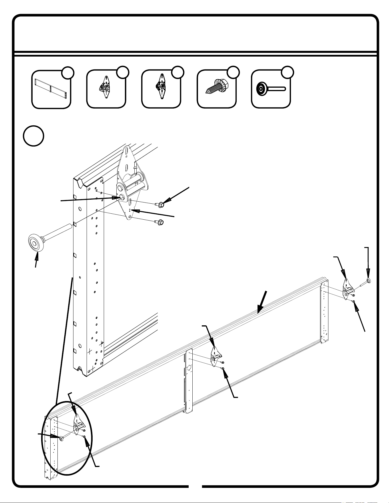
17
Step 25: #3 Panel
86GW
86
#3 End Hinge
2
1/4” Sheet Metal
Screw
6
Roller
2
#1 Center Hinge
1
#1 Center
Hinge
1/4”
Sheet
Metal
Screws
#3 End
Hinge
Fasten end hinges marked #3 to top of section on each end stile. Use (2) 1/4” sheet metal screws per
hinge.
Make sure that the two slots are at top of hinge. Insert a roller into each end hinge as shown. Attach
#1 center hinge.
1
#3 End
Hinge
1/4”
Sheet Metal
Screws
1/4”
Sheet Metal
Screws
Roller
Roller
Roller
Carrier
Hinge
Number
1/4”
Sheet Metal
Screws
#3 Door Section
1
Roller
#3 Section
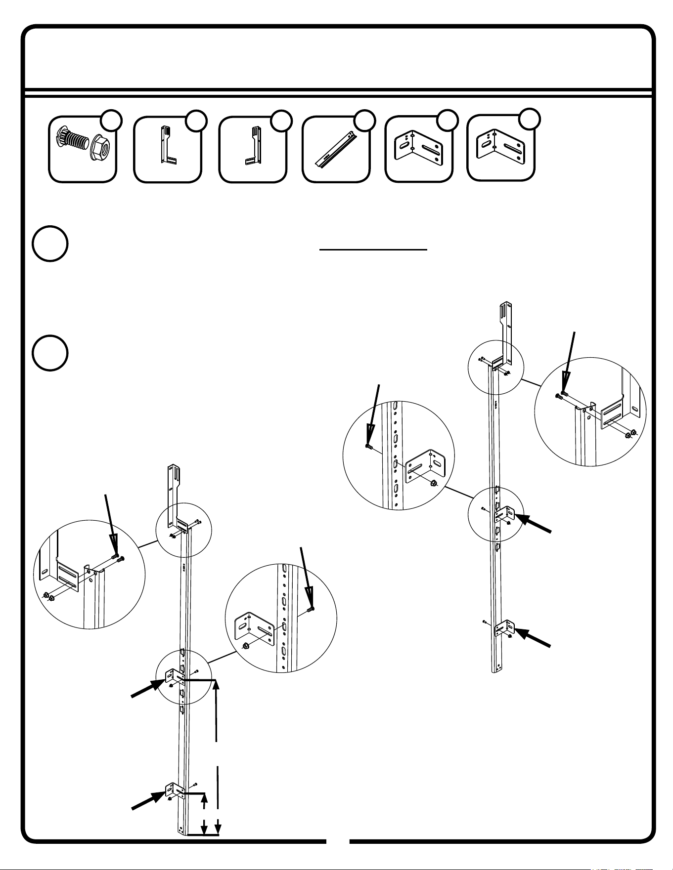
17
Step 26A: Track Installation
87GW
87
Prepare the Vertical Tracks.
1/4”
Bolts
The top of the vertical track must pitch back from the jamb for door to seal properly. This spacing is set
by use of graduated track brackets. Attach but do not fully tighten brackets to track with 1/4” x 5/8” track
bolts and nuts. The detail is shown with two different track brackets.
1
The fl ag angle mounts to the top of the track with
(2) 1/4” x 5/8” track bolts and nuts. This bracket
joins the vertical and horizontal tracks as well as the
angle attached to the horizontal track. Leave bolts
loose at this time. You will adjust the track after it is
installed to the jambs.
2
Always place heads of bolts to inside of the track.
This will prevent rollers from striking bolts.
Flag Angle Right
1
Vertical Track
2
Flag Angle
Right
Right V
ertical Track
Track Bracket
1/4” x 5/8” Track
Bolt & Hex Nut
8
4.5 Track
Bracket
2
Left Vertical Track
Flag Angle
Left
1/4”
Bolt
1/4”
Bolts
1/4”
Bolt
Track Bracket
Flag Angle Left
1
5.5 Track
Bracket
2
4.5
Bracket
38”
(220,98 cm)
5.5
Bracket
4.5
Bracket
5.5
Bracket
10” (25,4 cm)
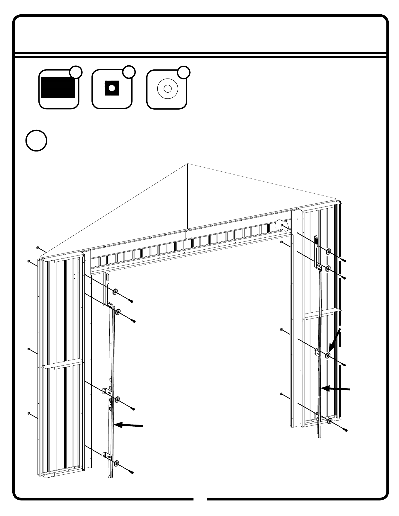
17
Step 26B: Track Installation
88GW
88
Right
V
ertical
Track
Left
Vertical
Track
Fasten the vertical track and fl
ag angle assembly to the door jamb using 1/4” Bolt and Hex Nut with
1” Washer. Follow the orientation as shown below. Do this for both the right and left vertical tracks.
3
1/4-20
Square
Nut
1” Washers
8
1” Washer
1/4-20x1/2”
Hex Head Bolt
1/4-20x1/2” Hex
Head Bolt
8
1/4-20 Square
Nut
8
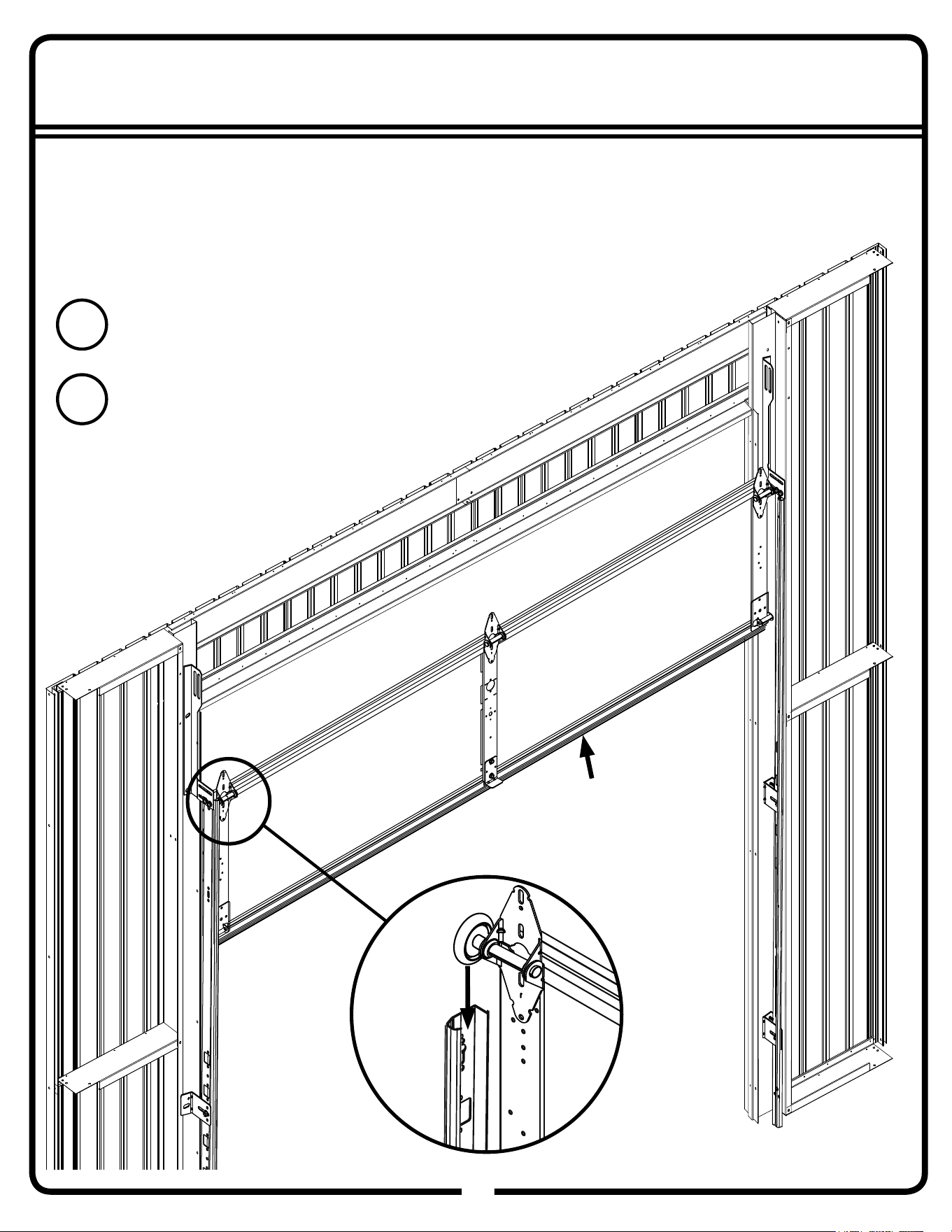
17
Step 27A: Insert Panels
89GW
89
Vertical
T
rack
Assemblies from Step 23:
•
Bottom Panel Subassembly
Bottom Panel
Assembly
Center and level bottom section in opening. If there
is a gap on one end at the fl oor then the track will not
rest on the fl oor by the same amount. Check this when
vertical tracks are in place.
2
Insert the bottom section into the doorway. Slide the
rollers into the vertical track as shown.
1
Roller
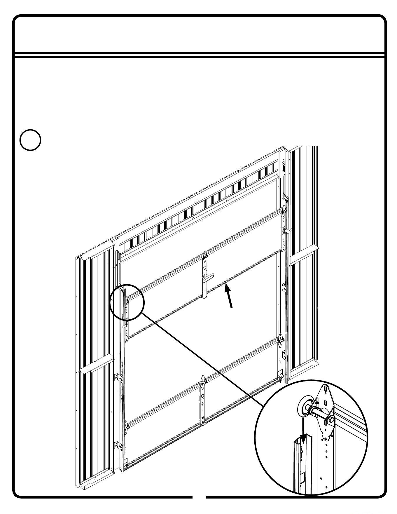
17
Step 27B: Insert Panels
90GW
90
Stack #2 section (with #2 end hinges) on top of bottom (#1) section while sliding
rollers into vertical track.
3
Assemblies from Step 24:
• #2 Panel Subassembly
#2 Panel
Assembly
Vertical
Track
Roller
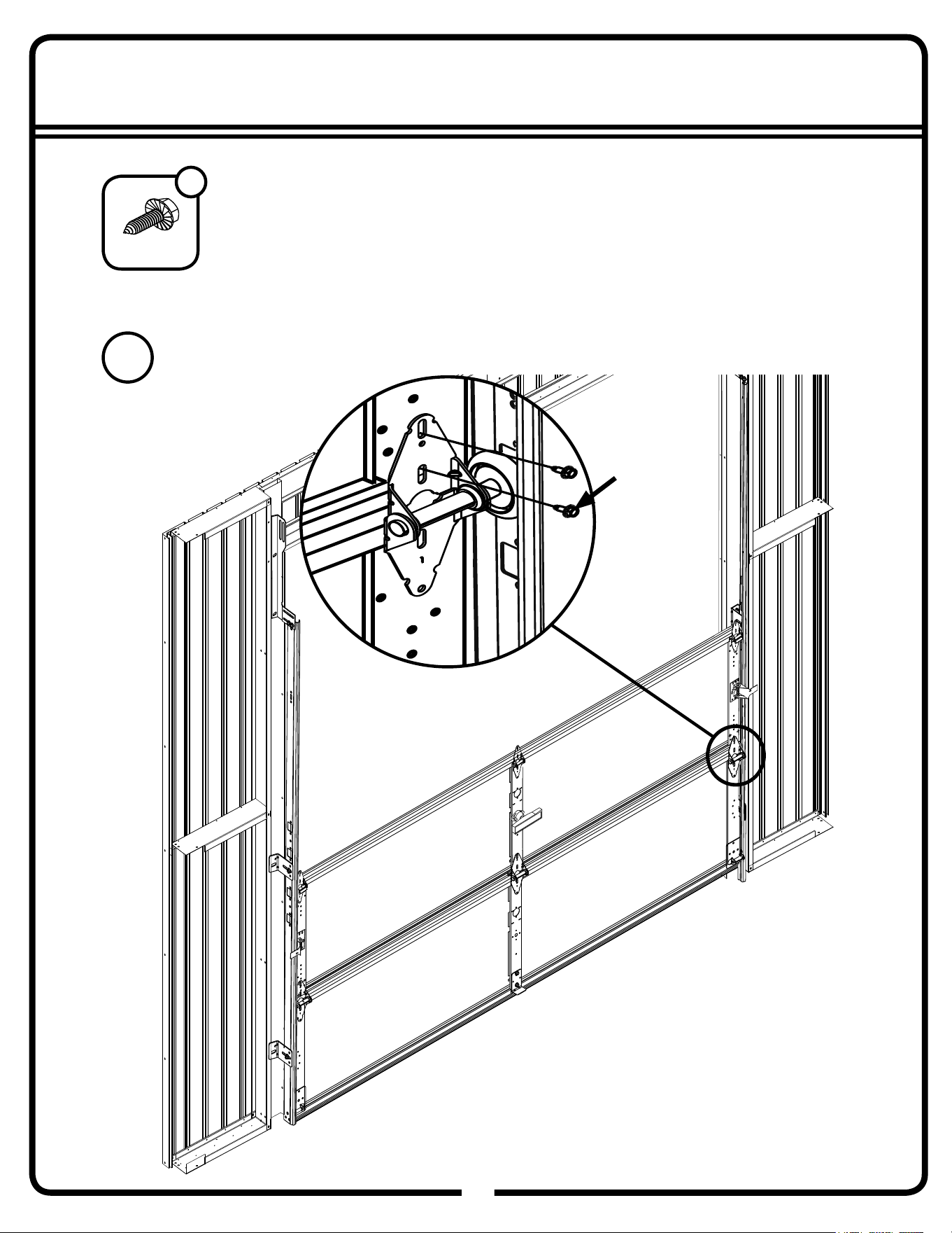
17
Step 27C: Insert Panels
91GW
91
1/4” Sheet
Metal Screws
Attach the #1 end hinges and center hinge to the #2 section with
1/4” sheet metal screws.
4
1/4” Sheet Metal
Screw
6
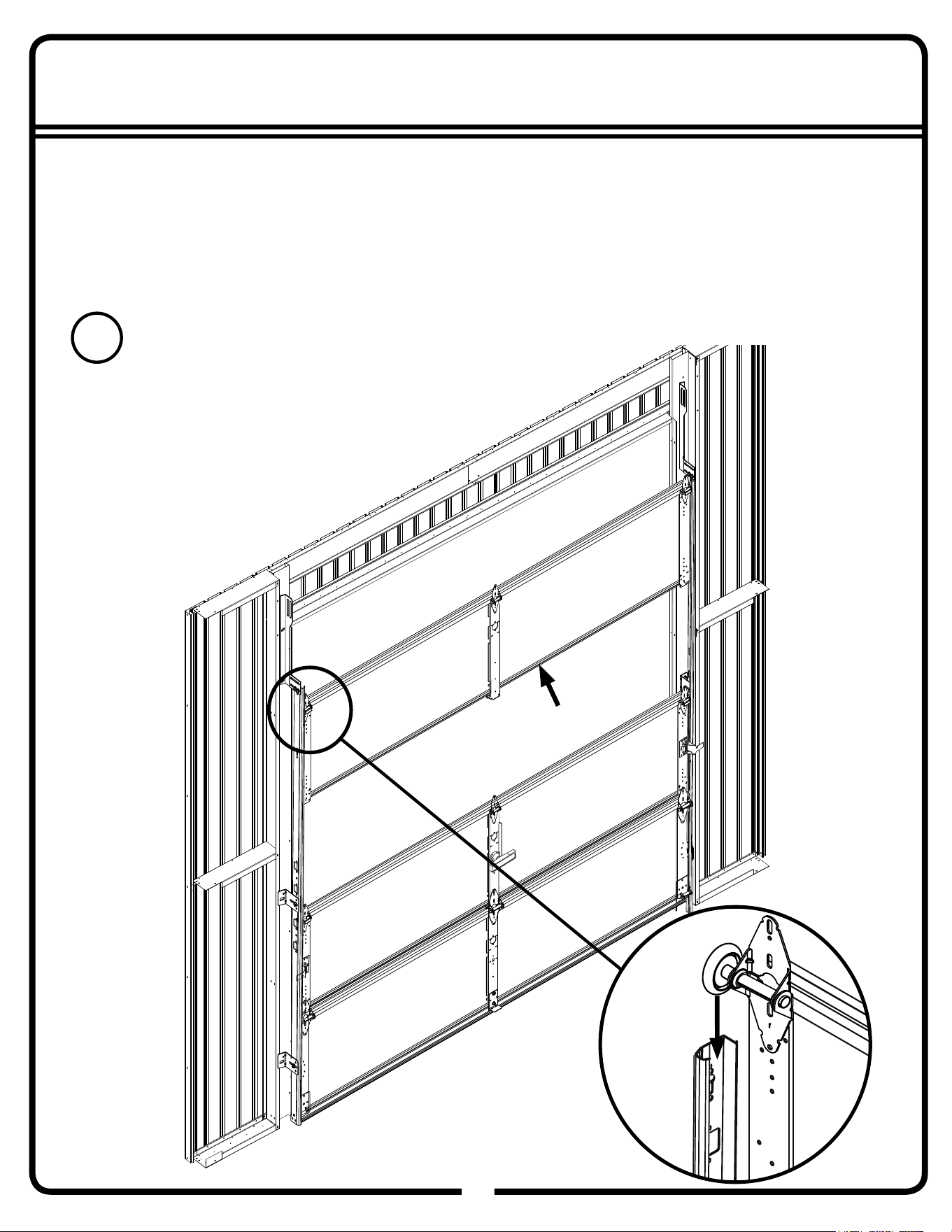
17
Step 27D: Insert Panels
92GW
92
Stack #3 section (with #3 end hinges) on top of #2 section while
sliding rollers into vertical track.
5
Assemblies from Step 25:
• #3 Panel Subassembly
#3 Panel
Assembly
Vertical
Track
Roller
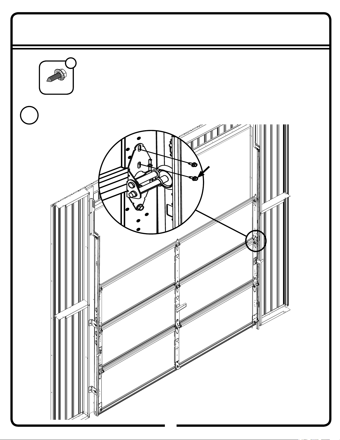
17
Step 27E: Insert Panels
93GW
93
Attach the #2 end hinges and center hinge to the #3 section with
1/4” sheet metal screws.
6
1/4” Sheet
Metal Screws
1/4” Sheet Metal
Screw
6
2
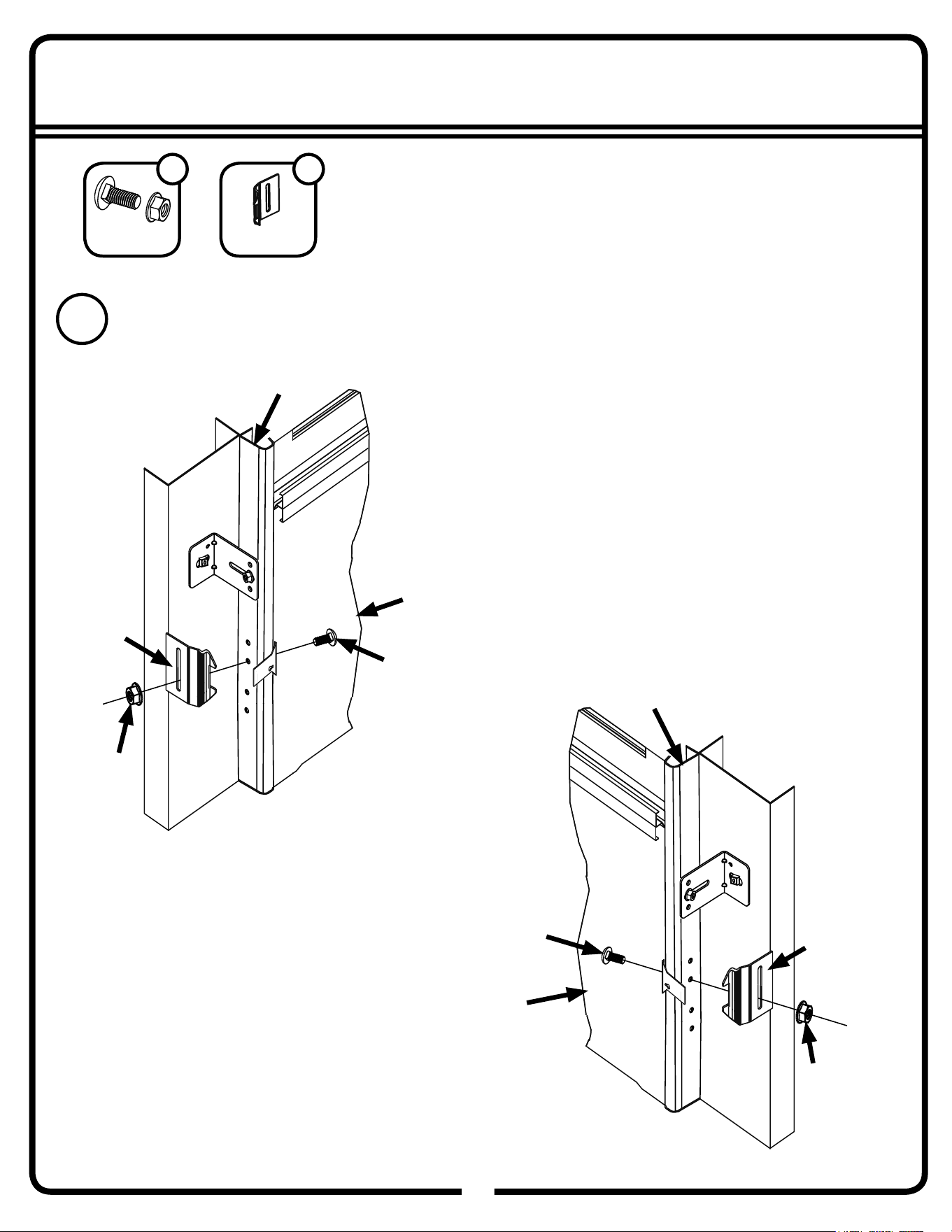
17
Step 28: Snap Latch Keeper
94GW
94
snap latch
keeper
1/4”
hex nut
right hand
vertical track
1/4” x 5/8”
track bolt
#2 Panel
Assembly
Attach a snap latch keeper to each vertical track using a
bolt and nut.
1
1/4” x 5/8” Track
Bolt & Hex Nut
2
Snap Latch
Keeper
2
left hand
vertical track
snap latch
keeper
#2 Panel Assembly
1/4”
hex nut
1/4” x 5/8”
track bolt
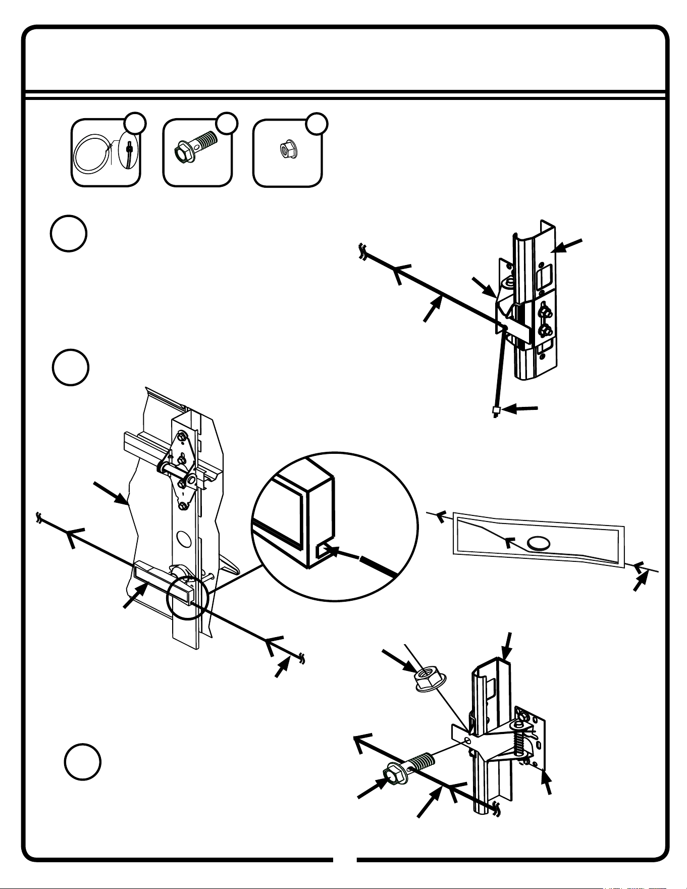
17
Step 29: Thread Cable
95GW
95
1/4” HEX BOLT WITH
HOLE FOR CABLE
1/4”
wiz nut
snap latch
right hand
vertical track
section #2
inside
handle
cable inserted
into hex bolt
Feed the cable through the inside
handle.
2
Cable
1
Thread cable through 1/4” hex bolt hole.
Insert the hex bolt into the snap latch.
Tighten with 1/4” wiz nut.
3
Hex Bolt with
Hole
1
1/4” Wiz Nut
1
cable
left hand
vertical track
lug end
of cable
cable
Insert cable through left snap latch hole. Place
a lug on the end of the cable to prevent it from
sliding out.
1
snap latch
cable
Inside View
of Handle
cable
inside
handle
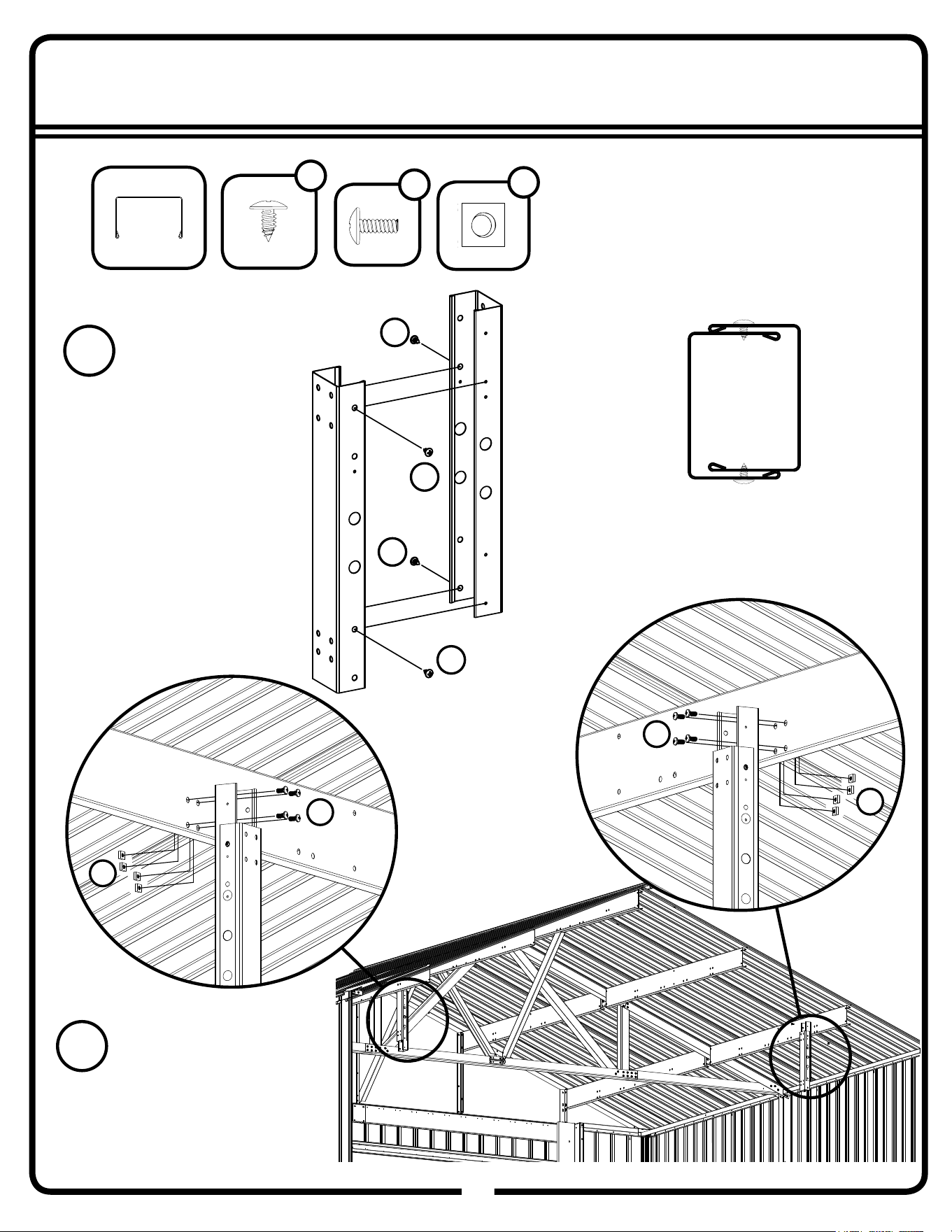
17
Step 30A: Horizontal Track
96GW
96
Roof Beam
Attach door track support
assembly
to roof beam using
four bolts and square nuts.
2
11197
(x2)
BS
BS
BS
BS
11197
11197
11197
11197
1
N
Assemble door track supports
using screws.
TOP VIEW
BB
N
FRONT
BB
(x4)
66611
BS
(x8)
65943
BB
(x8)
65106
N
(x8)
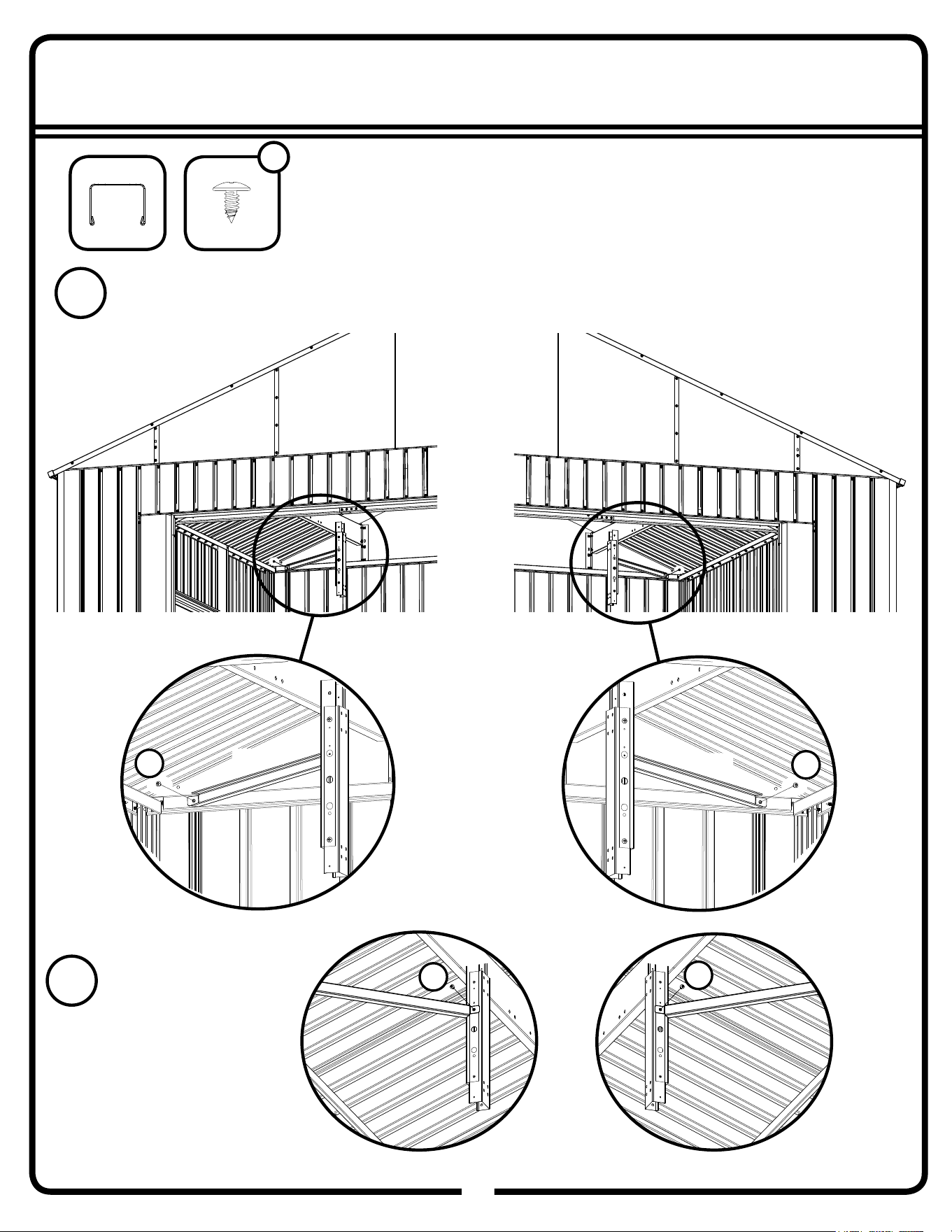
17
Step 30B: Horizontal Track
97GW
97
3
11183
11183
Attach track strut to rear frame using one screw.
VIEW FACING
REAR
BS
(x2)
12x10
BS
11183
BS
BS
VIEW FACING
FRONT
4
Attach track strut to door
track support assembly
using one screw.
66611
BS
(x4)
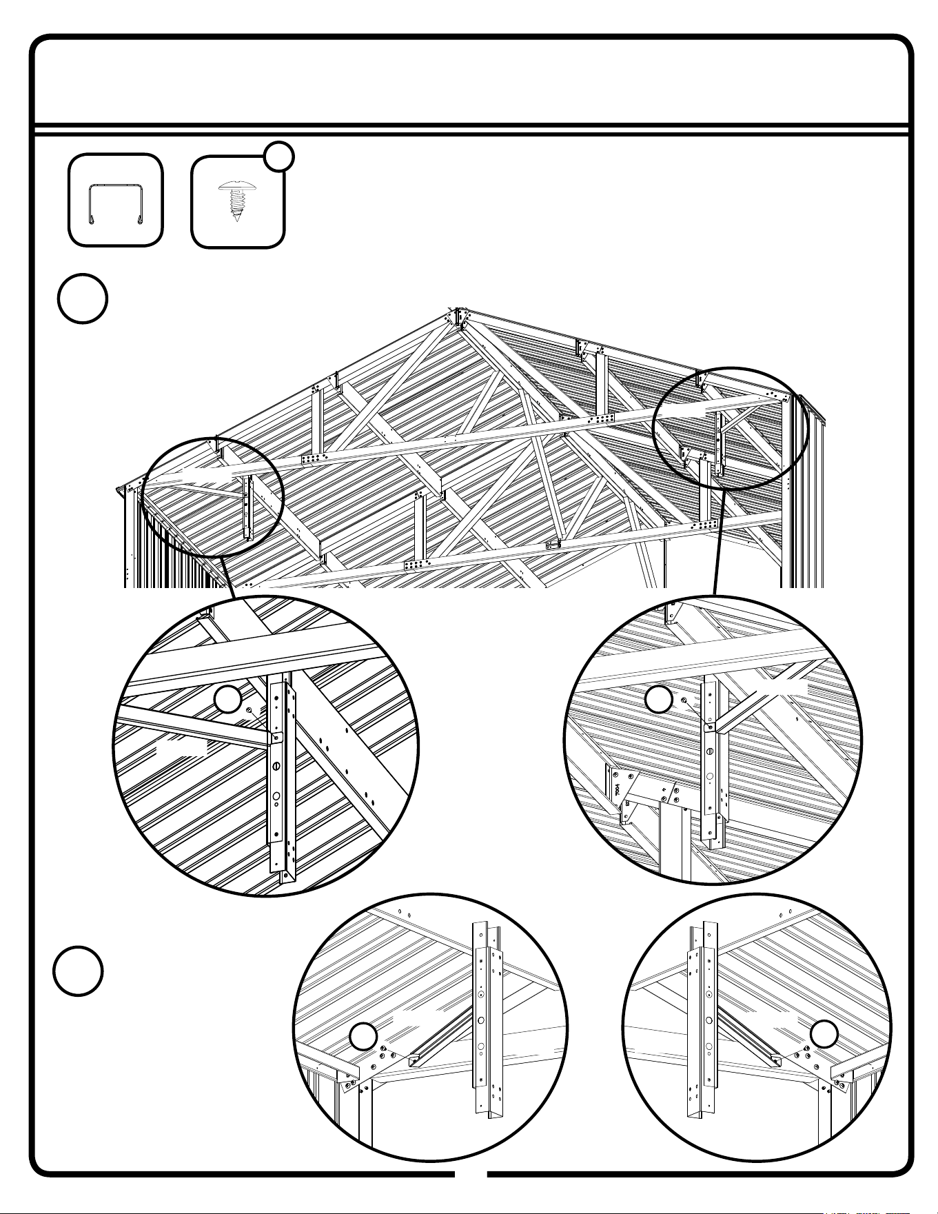
17
Step 30C: Horizontal Track
98GW
98
5
11183
11183
Attach track strut to door track support
assembly using one screw.
FRONT
VIEW FACING
FRONT
BS
(x2)
12x15+
Truss
Truss
Truss
11183
11183
Truss
VIEW FACING
REAR
BS
BS
BS
11183
6
Attach track strut to truss
using one screw.
66611
BS
(x4)
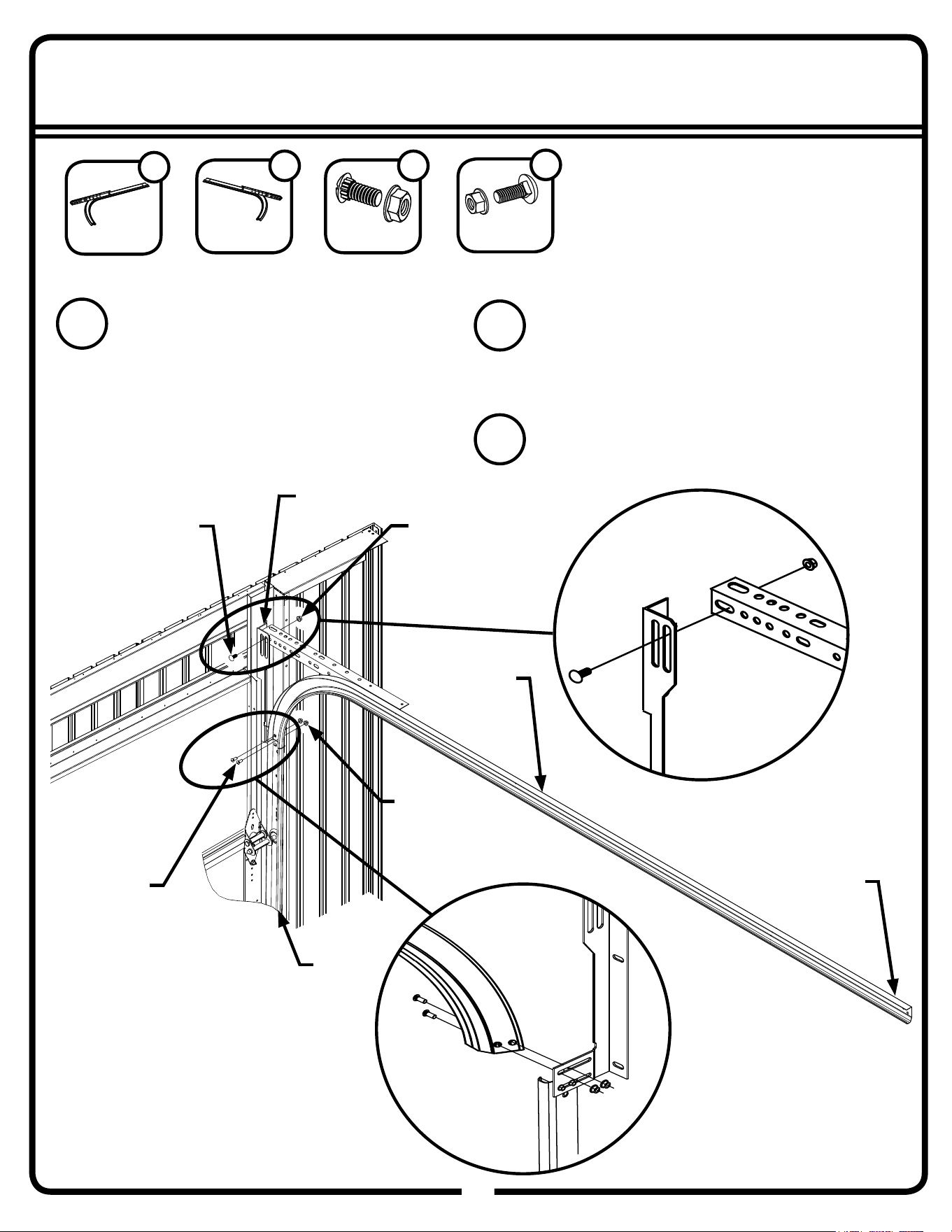
17
Step 30D: Horizontal Track
99GW
99
3/8” x 3/4”
Carriage Bolt
Have another person hold the end of the
l
eft horizontal curve track. Fasten the front
of the track to fl ag angle with (2) 1/4” x
5/8” track bolts and nuts. Always place
heads of bolts to inside of the track. This
will prevent rollers from striking bolts.
7
Fasten angle (attached to horizontal curve
track) to fl ag angle with 3/8” x 3/4” carriage
bolt and nut. Always place heads of bolts
on same side as the door sections. This will
prevent door from striking bolts.
8
Flag Angle
3/8” Nut
1/4” Nut
1/4” x 5/8”
Track Bolts
Vertical
Track
Left Horizontal
Curve Track
Right Horizontal
Curve Track
1
3/8” x 3/4” Carriage
Bolt and Hex Nut
2
1/4” x 5/8” Track
Bolt & Hex Nut
4
HOLD UP END OF
TRACK OR USE
ROPE PROVIDED
Left Horizontal
Curve Track
1
Repeat for right horizontal curve track.
9
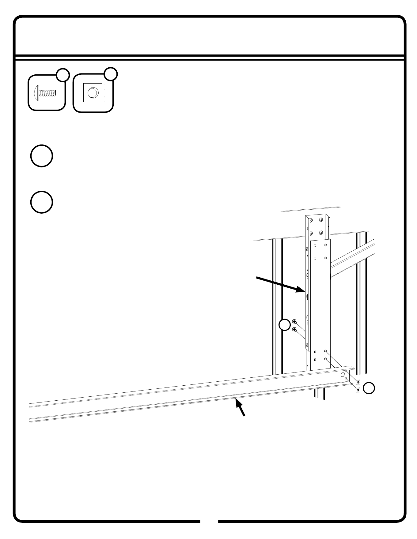
17
Step 30E: Horizontal Track
100GW
100
Attach the end of the Left Horizontal Curve Track to the Door Track
Support Assembly using bolts and nuts as shown.
10
Left Horizontal
Curve Track
Repeat for Right Horizontal Track.
Door Track Support
Assembly
BB
N
11
65943
BB
(x4)
65106
N
(x4)
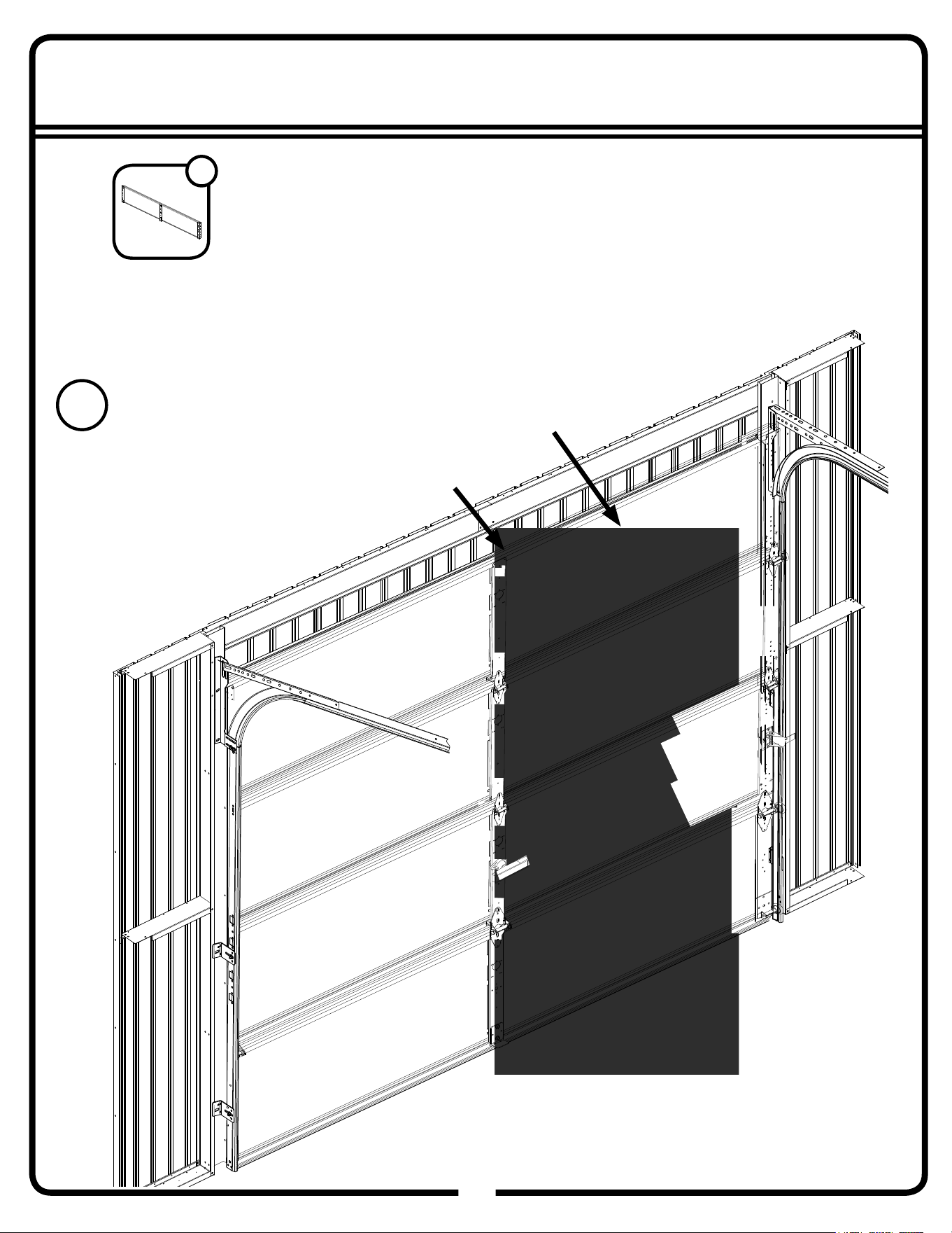
17
Step 31A: Insert Top Panel
101GW
101
Hold Section
in Place
Top
Section
Top Door Section
1
Assembling the top door panel will require another person holding the door section while
attaching the fi xtures and hinges. Make sure adequate help is available before continuing
on with the installation.
Have someone stack the top section on top of the other door
sections and hold it there.
1
17
Step 31B: Insert Top Panel
102GW
102
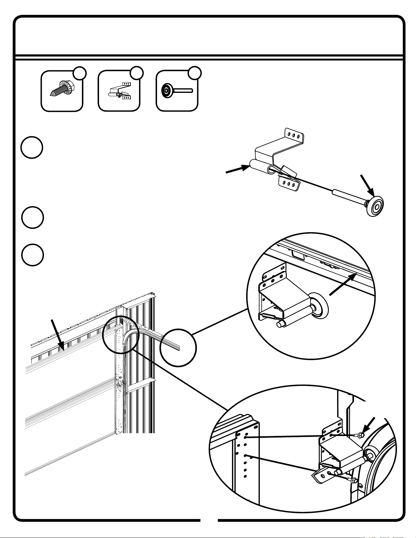
Slide the roller into the horizontal track where it is wide enough to put the
roller as shown. You may have to angle it in.
3
Top
Section
Slide the roller through the track so it lines up with the top
track. Attach the top fi xture to the top section using 1/4”
sheet metal screws.
4
1/4” Sheet Metal
Screw
2
1/4” Sheet
Metal Screws
Top
Fixture
Roller
Place a roller inside of a top fi xture.
2
Top Fixture
1
Roller
1
17
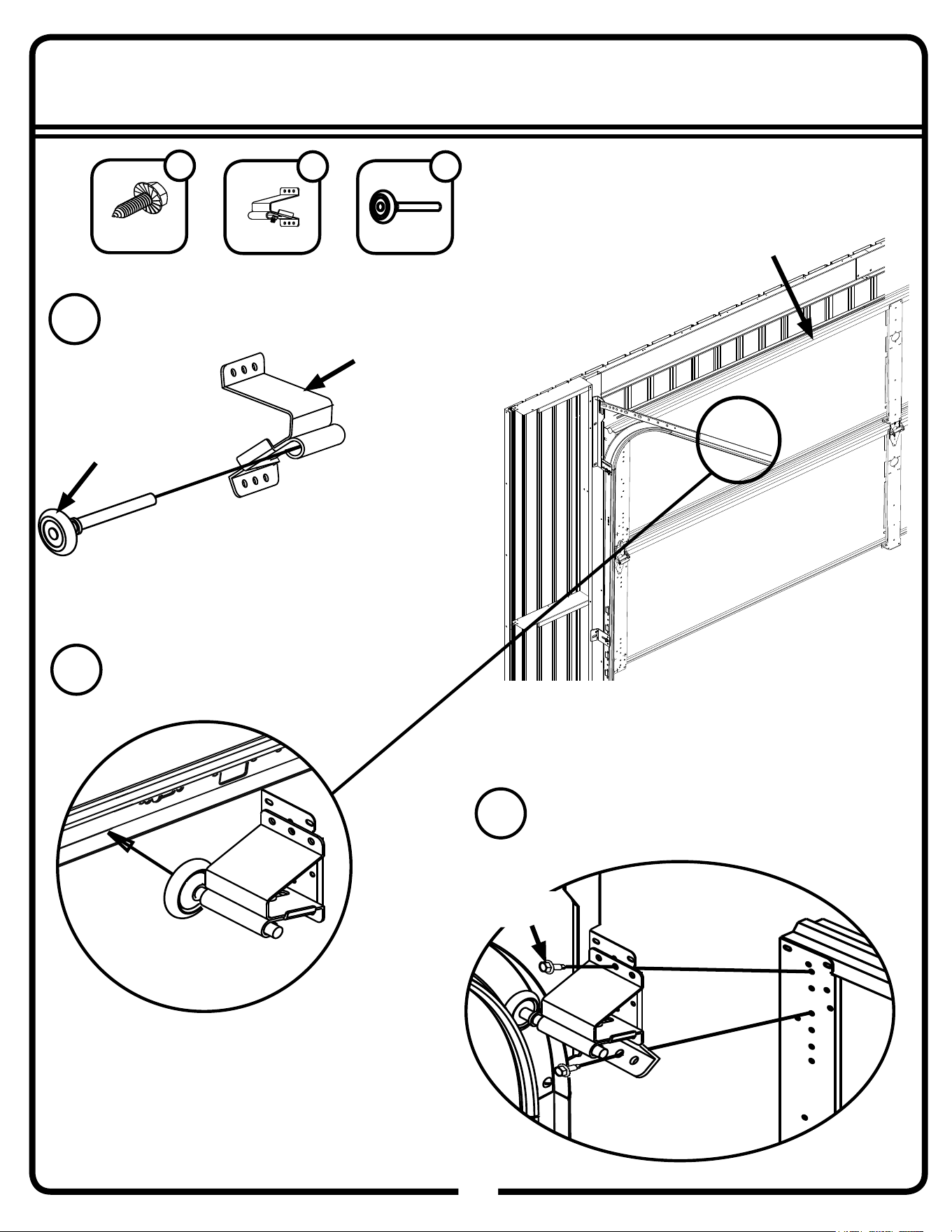
Step 31C: Insert Top Panel
103GW
103
Place another roller into the other top fi xture.
5
Top Fixture
1
Roller
1
Top
Fixture
Roller
Slide the roller into the horizontal track
where it is wide enough to put the roller
as shown. You may have to angle it in.
6
Slide the roller through the track so it lines up
with the top track. Attach the top fi xture to the top
section using 1/4” sheet metal screws.
7
1/4” Sheet Metal
Screw
2
1/4” Sheet
Metal Screws
Top
Section
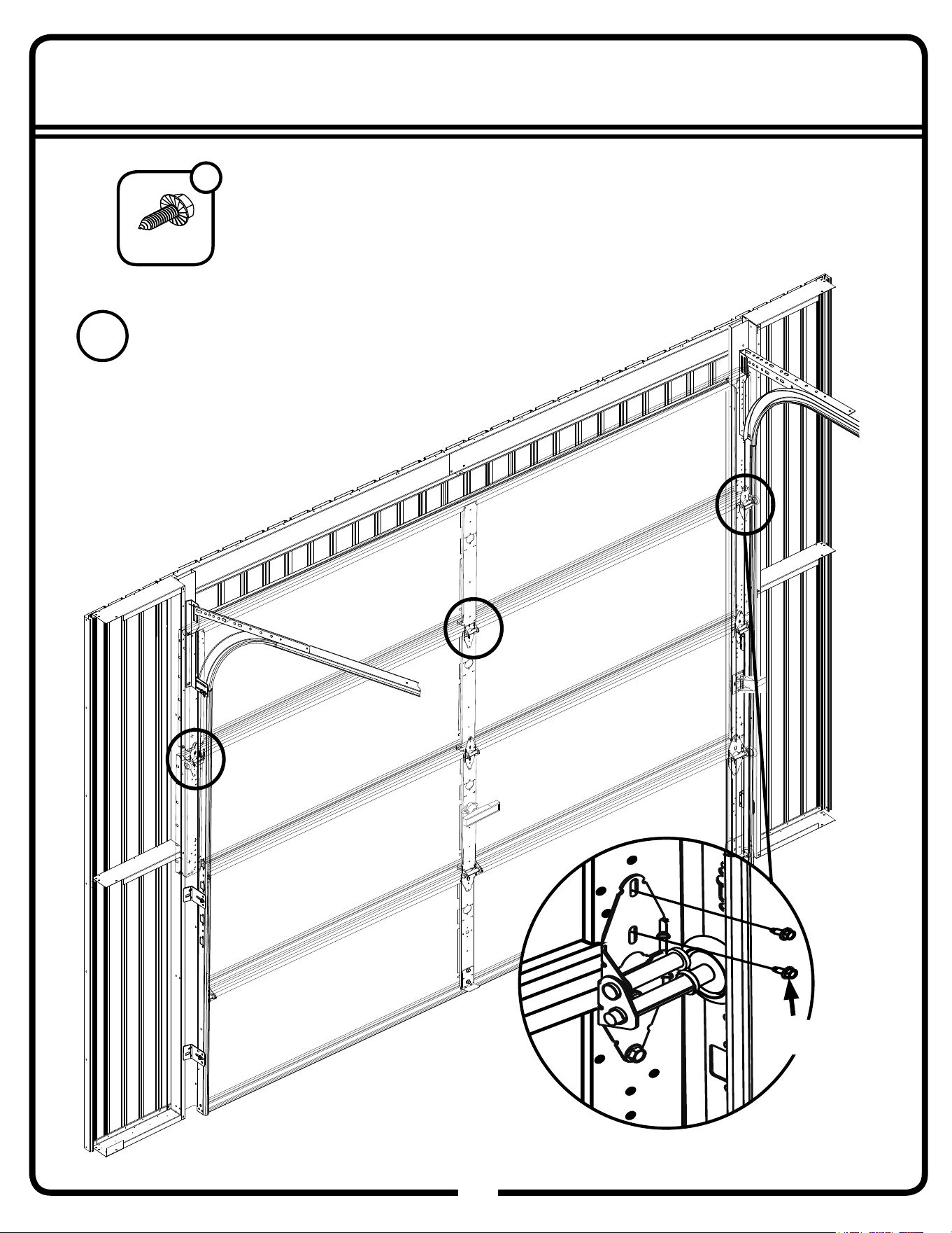
17
Step 31D: Insert Top Panel
104GW
104
1/4” Sheet Metal
Screw
6
Attach the #3 end hinges and center hinge to the top section with 1/4”
sheet metal screws.
8
1/4” Sheet
Metal Screws
3
17
Spring Assembly Preparation
105GW
105
Check all spring assembly instructions and parts.
Warning! If there appears to be any parts missing stop here and contact your Arrow Customer Service im-
mediately. Do not substitute parts.
Warning! Do not remove any factory applied spring tag or warning label! If any tags or labels are missing or
unreadable, contact your Arrow Customer Service immediately.
Warning! Never place your fi ngers in or near section joints while the door is moving.
Take time to study the parts and identify them.
Extension Springs: Extension springs mount alongside the horizontal track. They stretch as the door is closed and
contract as the door opens. This type of spring is always used in pairs, one on each side of the door. Both springs are
the same, it will not matter which one you assemble fi rst.
Safety Cable: Extension springs can cause severe damage, personal injury or even death if they are not properly
restrained. In the event of a spring failure the safety cable will prevent the spring from being propelled away from the
door.
17
Step 32A: Extension Spring Assembly
106GW
106
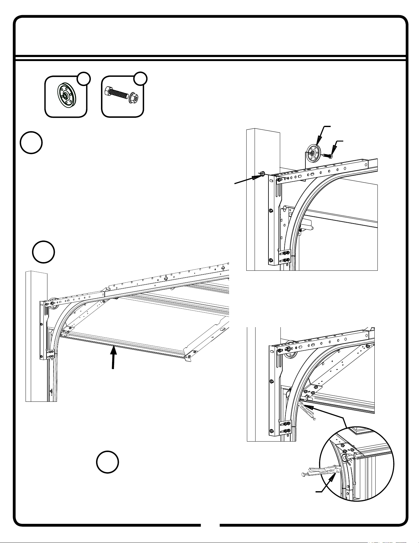
Attach pulley with a 3/8” x 1-1/2” bolt and hex nut on
angle which attaches horizontal track to fl ag angle.
Repeat this step for opposite side of door.
1
3/8” Hex Nut
3/8” x 1-1/2”
Bolt
Pulley
Clamp locking pliers
to back leg of track
REVERSE SIDE
With a minimum of two people, raise door
to fully open position.
2
Secure the door fi rmly at both sides
with locking piers. Connected to the
track as shown.
3
Pulley
2
3/8” x 1-1/2” Bolt
and Hex Nut
2
17
Step 32B: Extension Spring Assembly
107GW
107
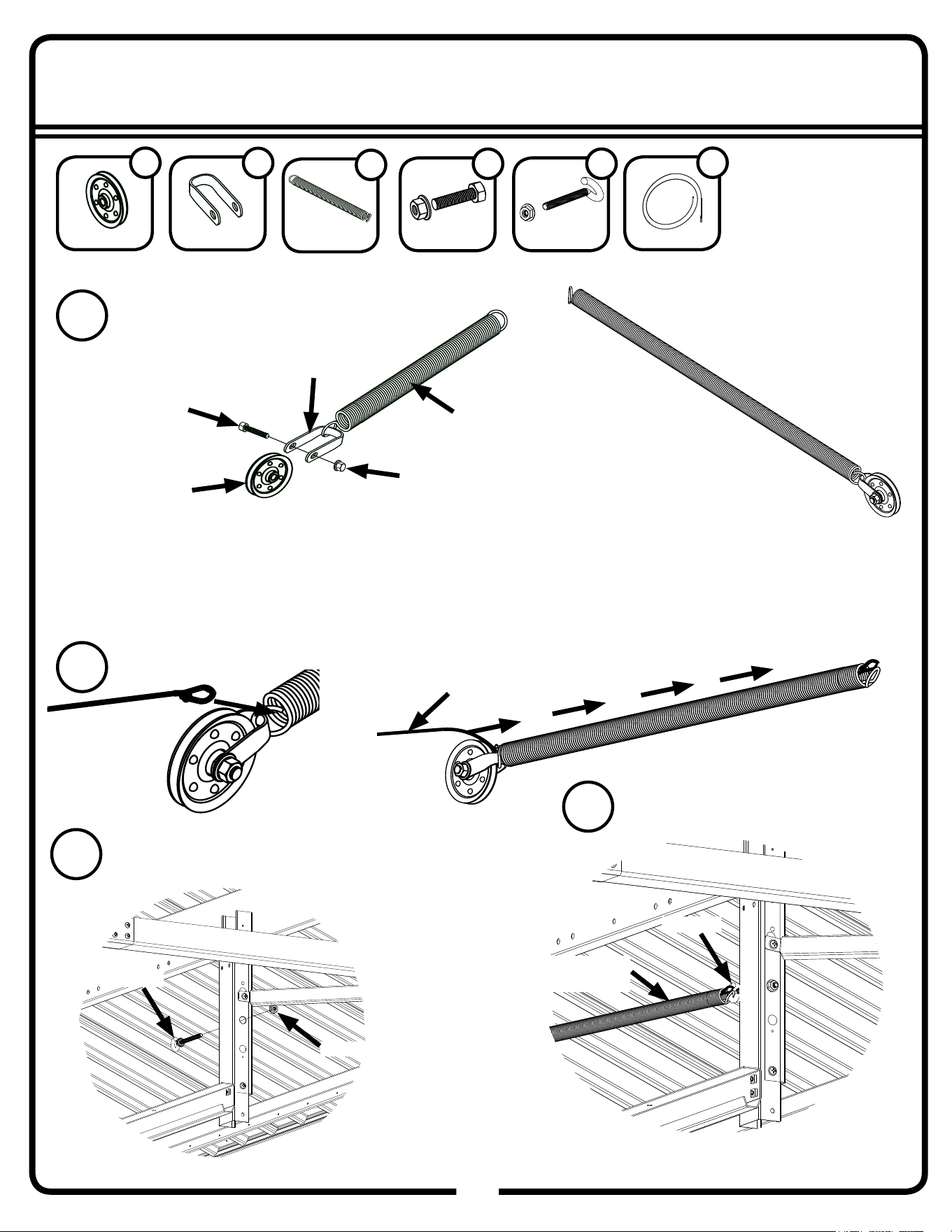
Assemble spring as shown. Bolt a clevis and
pulley on one end
4
Both springs are the same, it will not matter which one you assemble fi rst.
The spring cable is thicker than the safety cable. Be sure to use the correct cable for the appropriate step.
Thread safety cable through spring assembly.
5
Warning! Extension springs can cause severe damage, personal injury or even death if they are not properly
restrained. In the event of a spring failure the safety cable will prevent the spring from being propelled away
from the door.
Pulley
Clevis
3/8” x 1-1/2” Bolt
Extension Spring
Safety
Cable
Extension
Spring
2
Pulley
2
3/8” x 1-1/2” Bolt
and Hex Nut
2
Safety Cable
2
Clevis
2
Hex Nut
Attach eyeblots to both door track
support assemblies.
6
Eyebolt and Hex
Nut
2
Hook end of safety cable and
spring assembly to eyebolts.
7
Safety Cable and
Spring Assembly
Eyebolt
Eyebolt
Hex Nut
17
Step 32C: Extension Spring Assembly
108GW
108
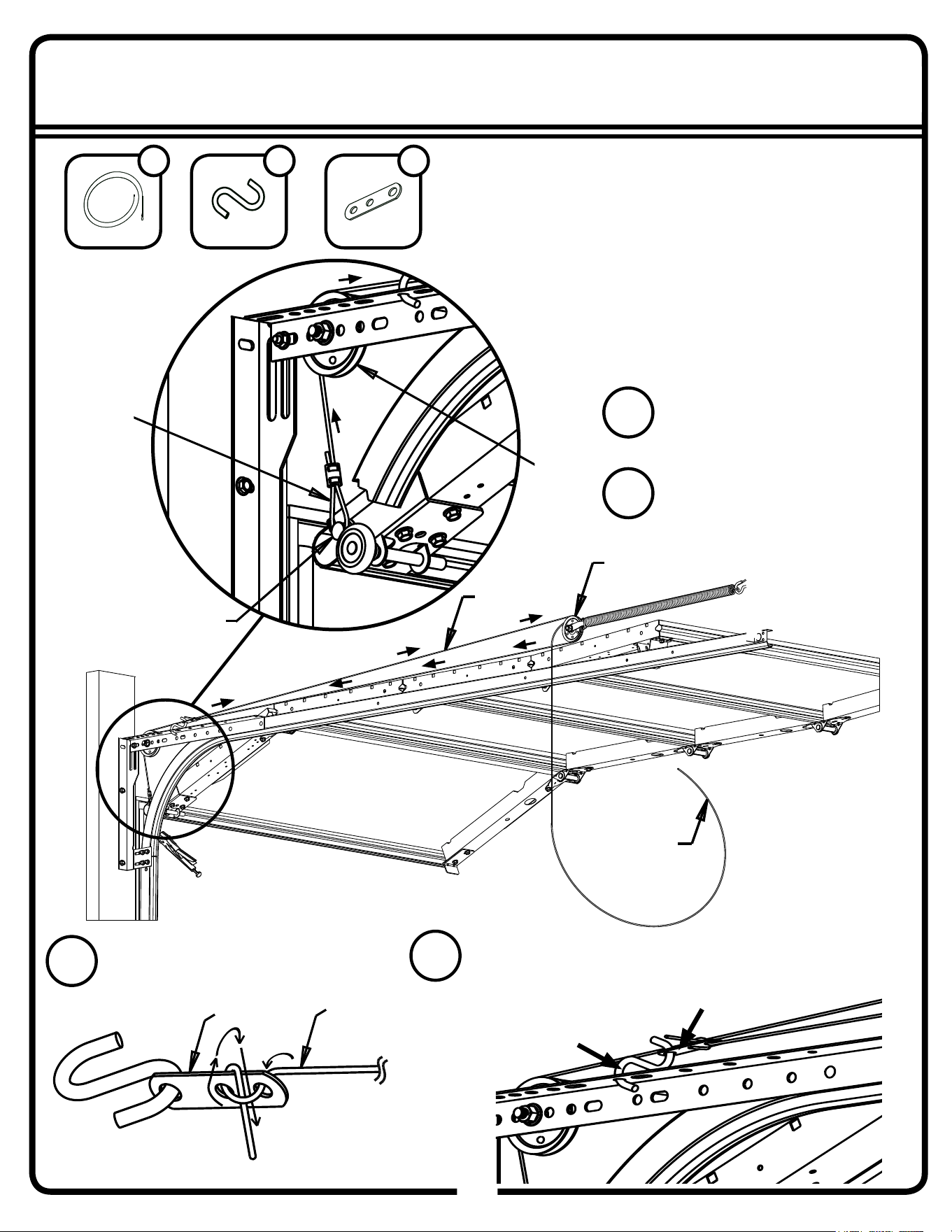
Attach spring cable loop to bottom
fi xture stud and thread spring cable
over pulley.
8
Thread spring cable
around spring pulley.
9
Spring
Cable Loop
Bottom
Fixture Stud
Pulley
Spring Cable
2
S Hook
2
Cable Clip
2
Spring
Cable
Spring
Pulley
Safety Cable
Tie a cable clip to the spring cable
and connect it to an S-hook.
Cable Clip
Spring
Cable
Stretch spring 2”-3” and clip the S-hook to a hole in the hori-
zontal angle. This is referred to as initial stretch and may need
adjustment (see end of extension spring assembly details).
11
Cable Clip
S-Hook
10
17
Step 32D: Extension Spring Assembly
109GW
109
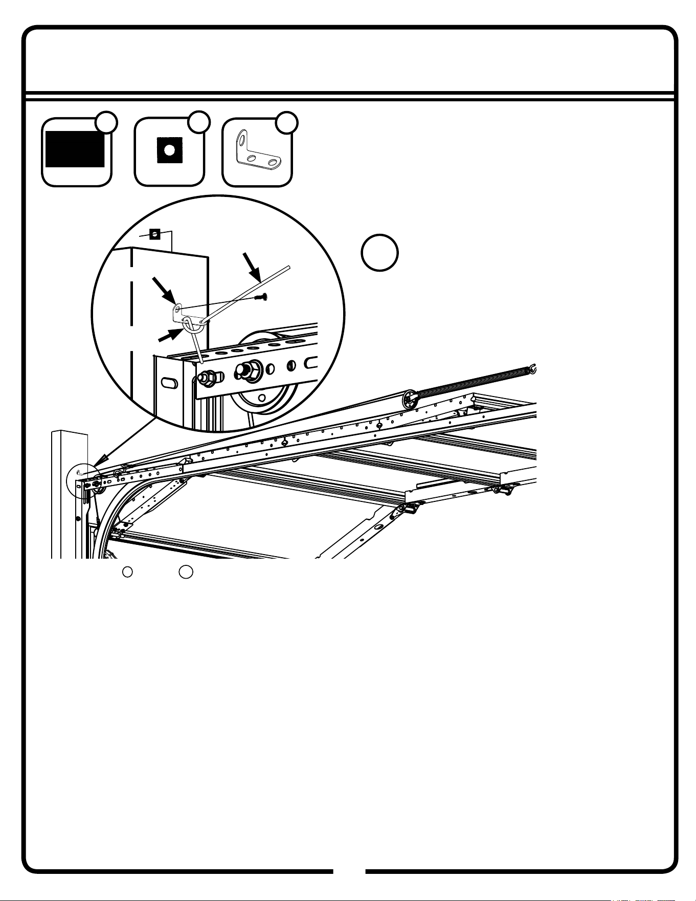
Attach cable clip to track support using bolt
and nut. Tie the safety cable securely to the
cable clip as shown.
12
Safety Cable
Cable Clip
Repeat steps 4 through 12 for the other spring.
Lowering the door and spring adjustment.
W
arning! Until all adjustments are completed, always assume you will have to physically support the full weight
of the door. Make sure adequate help is available.
Warning! Never place your fi ngers in or near section joints while the door is moving.
Warning! All spring component parts whether part of the spring assembly, attached to the door, or attached to
the wall are now under tension and are extremely dangerous.
Warning! Spring adjustments from this point onward must be performed in accordance with all warnings and
directions as previously stated.
Warning! Spring adjustments can only be performed when door is in fully open position and door restraints are
applied to tracks.
With one person holding door in the fully open position, carefully remove locking pliers.
Slowly lower door, testing the balance of the springs. If door does not lift off of the fl oor by itself, or does not roll back to
the fl oor when not supported, it is properly counterbalanced.
If door lifts off of fl oor by itself, the springs are too strong and the initial stretch must be reduced.
If door rolls back to fl oor, the springs are too weak and the initial stretch must be increased.
Finalize the track adjustments
Operate door through one full cycle. Check door stops and top fi xture for proper seal. If door is not functioning correctly,
check for binding against jamb, header or tracks.
Cable
Knot
1/4”
Bolt
Cable Clip
2
1/4-20x1/2” Hex
Head Bolt
2
1/4-20 Square
Nut
2
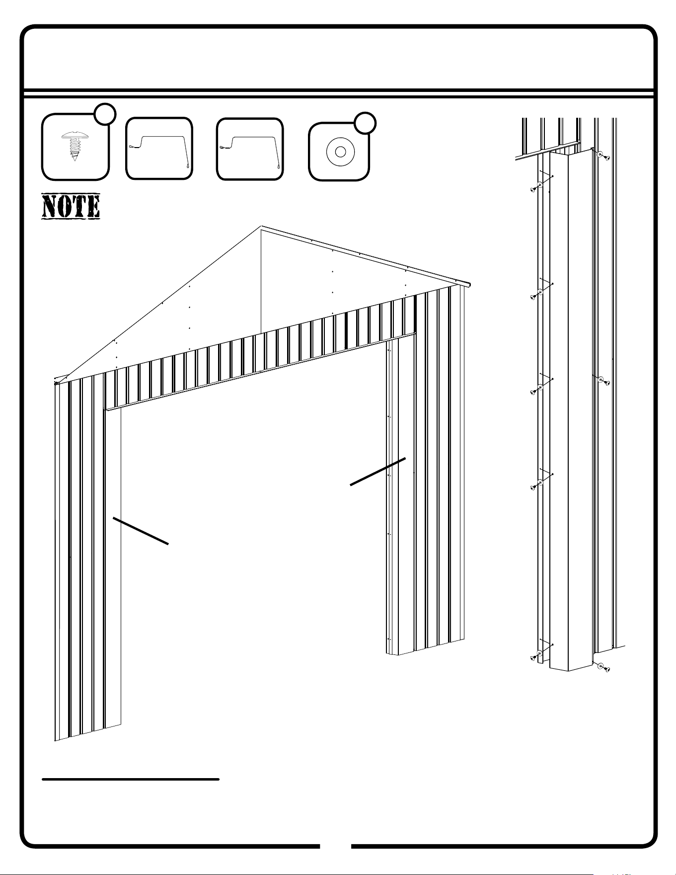
Step 33
110
110GW
11185
(x1)
11185
Front
11171
11171
(x1)
66646
W
(x16)
Painted fasteners are to be used on painted parts only.
Make sure painted fasteners match wall color.
IMPORTANT:
It is important that building be anchored after construction.
See page 6 for recommended ways of anchoring.
66611
WS
(x16)
ASSEMBLY NOTES
46A
111
ASSEMBLY NOTES
46A
112