
Installation
& Operation Manual
Commercial Glasswasher
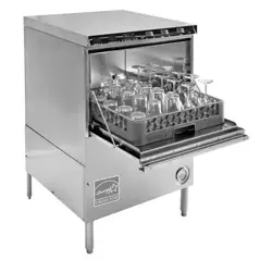
Model PKHT24A
PKHT24A.IO.1
Rev 5.29.25
Model PKHT24A Shown
Note: Some US States may require Energy Star ratings for Commercial Dishwashers. The specier or
installer is responsible for knowing their local codes, standards, and regulatory requirements.

2
Commercial Glasswasher Installation & Operation Manual - PKHT24A
TABLE OF CONTENTS
Introduction ............................................................................................................................................ 3
Specications ........................................................................................................................................ 4
PKHT24A Operational Cycle ............................................................................................................... 5
Getting Started ....................................................................................................................................... 6
Receiving and Installation.................................................................................................................... 6
Electrical .............................................................................................................................................. 6
Plumbing.............................................................................................................................................. 6
BETA Detergent and Rinse Dispenser ................................................................................................ 7
Safety-Temp Feature ........................................................................................................................... 8
Booster Heater Setup .......................................................................................................................... 9
Installer Checklist ................................................................................................................................ 9
Operation .............................................................................................................................................. 10
Dema Flow Disc ................................................................................................................................ 10
Rinse and Wash Temperatures ......................................................................................................... 10
Startup Procedures............................................................................................................................ 10
Operating and Cleaning Instructions ................................................................................................. 11
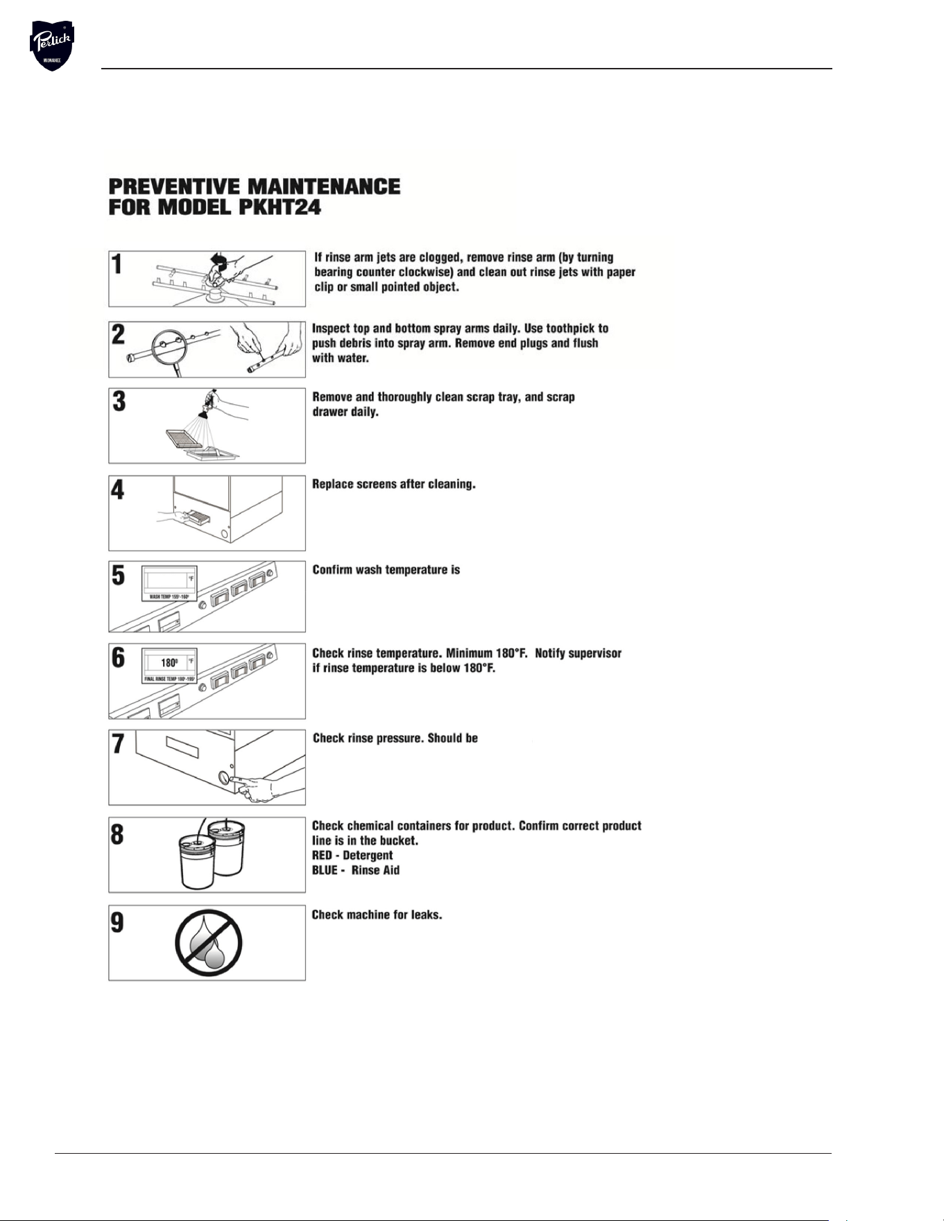
Preventative Maintenance Chart ....................................................................................................... 12
Quick Service Guide .......................................................................................................................... 13
Troubleshooting ................................................................................................................................. 14
Parts Kits .............................................................................................................................................. 16
Customer Notice ................................................................................................................................. 17
Electrical Diagrams ............................................................................................................................. 18

Commercial Glasswasher Installation & Operation Manual - PKHT24A
PKHT24A.IO.1
Rev 4.23.25
The PKHT24A is a hot water sanitizing, single rack, undercounter glasswasher. It is a stand-alone
machine featuring a self-contained booster heater. The only external connections necessary are power
supply, water supply, drainpipe, and optional chemical dispensers. The machine uses re-circulated
wash water and fresh water nal-rinse.
Operation of the PKHT24A is extremely user friendly. To initially ll the machine each day, push the
power switch to the “ON” position. The machine will automatically ll to the correct level. The wash tank
heater will maintain the wash water temperature at 160°F. The booster heater will produce a minimum
of 180°F nal rinse water each cycle.
The supply water to the PKHT24A must be a minimum of 120°F at 24 psi (Pounds per Square Inch)
with a 6 gpm (Gallons Per Minute) ow rate and 60 gph (Gallons Per Hour) recovery rate. The pipe
supplying the water must be a minimum of a 1/2”. The plumbing connection is located at the back of the
machine. (See specication sheet).The drain is a 1” barbed tting connection located at the upper left-
hand corner (facing the back) of the machine.
This manual provides a complete reference guide to the PKHT24A. The rst section explains how the
machine is packaged and what to look for when receiving the machine. This manual explains how to
install and set up the machine for use. Requirements are given for plumbing, wiring, and space
considerations. These are always taken into consideration by our well-trained sales representatives
prior to the order being placed. In the manual, guidance is also given for installation to ensure that the
machine will be able to run at optimum conditions.
The machine’s functions are mostly automatic and take little training to put into full operation. The
Operation section of the manual may be used for instruction and procedures when required. We make
this portion of the manual easy to understand so that all levels of operators are able to understand the
machine’s operation. The Operation section also includes diagnostic considerations for the machine
when problems occur.
We are committed to providing the best products and customer service, and we welcome your
feedback.
4
Commercial Glasswasher Installation & Operation Manual - PKHT24A
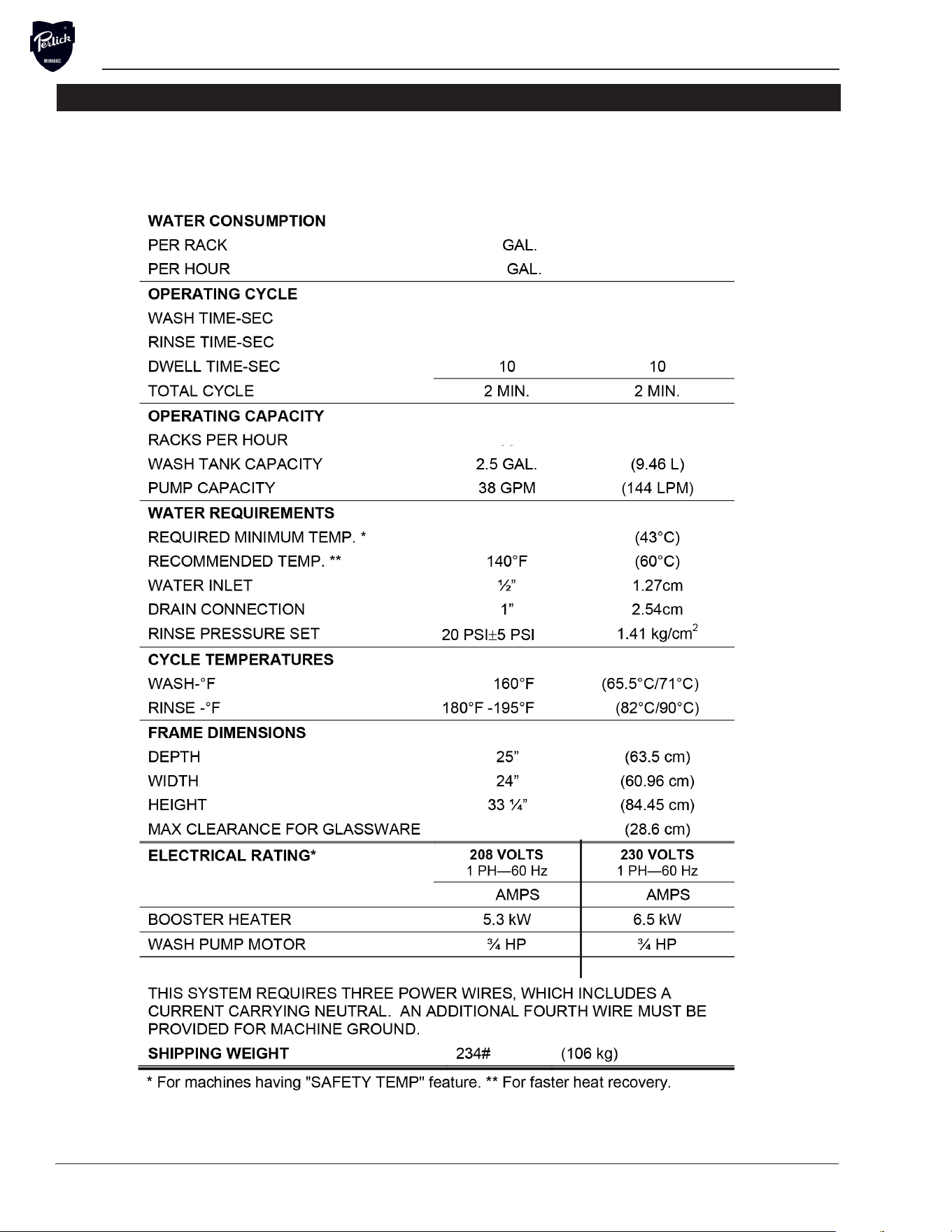
SPECIFICATIONS
METRIC EQUIVALENT
30
.68
(2.57)
99
28
120°F
14 1/4”
28
99
11 11
(72.1)
19
32
WASH TANK HEATER
2.2 kW 2.9 kW

Commercial Glasswasher Installation & Operation Manual - PKHT24A
PKHT24A.IO.1
Rev 4.23.25
OPERATIONAL CYCLE
The PKHT24 operational cycle has a total cycle time of 2 minutes (120 seconds). The steps listed be-
low detail the individual functions that are executed during each operational cycle.
1. With the machine powered up, toggling the START switch begins a cycle.
a) Toggling the START switch energizes both the Cam Timer motor and the Instant Start Relay. The
Instant Start Relay latches ON the power to the Cam Timer motor so that the START switch can be
released a moment after it has been toggled without the Cam Timer motor losing power.
b) After about 1.5 seconds the Cam Timer’s rst cam — the Cam Timer Motor Cam — latches ON
the power to the Cam Timer motor and drops out the Instant Start Relay. The Cam Timer motor
continues to run for a total of 2 minutes, at which time it switches OFF — resetting the Cam Timer —
and waits for the next START command.
2. The Cam Timer’s third cam controls the Wash Pump. The Wash Pump comes ON about 3 seconds
into the Operational Cycle and continues to run for 94 seconds. This 94-second period is the Wash
Cycle.
3. About 3 seconds after the Wash Cycle has completed the Cam Timer’s second cam, which
controls the Rinse Cycle, turns ON — energizing the Water Solenoid — and stays ON for 16 seconds.
This 16-second period is the Rinse Cycle.
4. When the Cam Timer assembly approaches the nal rinse portion of the cycle, the “Safe-T-Temp”
sixth micro switch will pause Cam Timer assembly if the booster heater has not reached 180 degrees.
The machine will remain in wash cycle mode until 180-degree rinse temperature is reached, and at
this time the Cam Timer will advance automatically into the rinse cycle and dispense 180 degrees rinse
water over the glassware.
5. The 4th cam controls the drain. The drain comes on before the Rinse Cycle ends and stays on until
the proper water level is reached.
6. Cam switches 6 and 7 control the detergent and rinse pumps respectively. They turn ON at the
beginning of the wash and rinse cycle respectively and run for a few seconds to provide sucient
detergent and rinse aid. These cams can be adjusted as necessary for proper chemical dosage. See
section 4.1.1 Cam Adjustment.
Note: Use only commercial-grade high temperature detergents and rinse additives recommended
by your chemical professional. Do not use detergents and rinse additives formulated for residential
dishwashers.

6
Commercial Glasswasher Installation & Operation Manual - PKHT24A
GETTING STARTED
Receiving and Installation
The glasswasher is shipped from the factory in a corrugated box on a wooden pallet. The installation
guidelines give a systematic procedure for setting up the machine.
Start by removing the packaging material. Unwrap the machine and check for the following component
parts:
The Wash Tank Scrap Screen is shipped inside the wash cavity of the machine. This screen must be in
place during operation. It has been designed to perform two basic functions:
1. Strain water that is circulating through the spray arms and pump assembly.
2. A basket to catch broken glass, or heavy solids that may plug the impeller.
Set the machine in place, and level from side-to-side and front-to-back. Steam generated from normal
operation may escape from door. Wood, laminates, veneers, etc. are unsuitable materials for use in
areas exposed to dishwasher steam and detergents. Stainless steel or other moisture-resistant shields
are recommended for surfaces adjacent to sides and tops of under counter dishwashers.
Electrical
1
Prior to installation make sure the electrical supply is compatible with the specications on the
machines data plate. Single-phase 208/240 volt, 60 Hz dedicated circuit should be used to supply
electrical energy to the PKHT24A Glasswasher (see specication sheet on page 4). This system
requires two power wires. An additional third wire must be provided for ground. Approximately 4-feet
of ¾” exible conduit with power leads (L-1, L-2, Ground) extending out of the conduit are provided for
easily connecting the power at installation. The power connection must be located such that there is
sucient length of the exible conduit remaining to permit the machine to be moved for cleaning.
WARNING: Electrical and grounding connections must comply with local electrical codes.
Plumbing
2
Warning: The plumber connecting this machine is responsible for making certain that
the water lines are THOROUGHLY FLUSHED OUT BEFORE connecting the dishwasher
The machine is equipped with a 1/2” NPT connection located at the lower left-hand corner (facing the
back) of the machine. A 140°F water line should be plumbed to this point (see specication sheet). The
water line used must be of sucient length and exibility to permit the machine to be moved for
cleaning.
1,2
All electrical and plumbing connections must be made by a qualied person who will comply with all available federal, state,
and local health, electrical, plumbing and safety codes.
Note: For supply connections, use copper
wire only rated at 90°C minimum.

Commercial Glasswasher Installation & Operation Manual - PKHT24A
PKHT24A.IO.1
Rev 4.23.25
The supply water to the PKHT24A must be a minimum of 120°F at 24 psi (Pounds per Square Inch)
with a 6 gpm (Gallons Per Minute) ow rate and 60 gph (Gallons Per Hour) recovery rate. The pipe
supplying the water must be ½” minimum. The plumbing connection is located at the back of the
machine. (See specication sheet on page 4).
WARNING: If water pressure exceeds 50 psi, pressure reducing valve (PRV) is recommended.
WARNING: Perlick recommends utilizing a water softening system to maintain water hardness
measurements of 3.5 gpg (grains per gallon) or less. This will assure maximum results and optimum
operation of the dish machine.
Detergent And Rinse Dispenser
The built-in chemical dispenser assembly has easy access for chemical settings on the cam timer.
Note: Use only commercial-grade detergents and rinse aids recommended by your chemical
professional. Do not use detergents and rinse aids formulated for residential dishwasers.

8
Commercial Glasswasher Installation & Operation Manual - PKHT24A
Safety-Temp Feature
The Safety-Temp feature assures the nal rinse cycle is always at a consistent minimum of 180
degrees.
How it works: The Safety-Temp function operates o the fth cam (labeled “SafeTtemp”) on the
timer assembly. When the cam timer assembly completes the wash cycle, and approaches the nal
rinse portion of the cycle, the Safety-Temp micro switch will drop into the cam slot and pause the cam
timer assembly if the booster heater has not reached 180 degrees. The machine will remain in wash
cycle mode until 180 degree rinse temperature is met, and at this time the cam timer will advance
automatically into the rinse cycle and dispense 180 degrees rinse water over the glassware.

Commercial Glasswasher Installation & Operation Manual - PKHT24A
PKHT24A.IO.1
Rev 4.23.25
Installer Checklist
r Glasswasher checked for concealed damage
r Hot water supply is 120° F (60 C) — minimum
r Incoming water supply line is ½” — minimum
r Incoming water supply is 6 GPM minimum at 24 psi
r Supply circuit breaker for machine is properly sized (40 amp)
r Service voltage and phase type are correct to machine data plate
r Drain hose is installed with air gap (discharge 1” above drain)
r Glasswasher is properly grounded
r Glasswasher is properly leveled
r Machine circuit breaker is labeled “GLASSWASHER”
r Machine has been “hard-wired” with correctly sized wire

10
Commercial Glasswasher Installation & Operation Manual - PKHT24A
OPERATION
Initial Setup
Rinse and Wash Temperatures
1. Turn the Power switch to the “ON” position.
2. After the machine has warmed up for about 10-15 minutes, note the wash and rinse temperatures.
The wash temperature must be 160°F minimum. The rinse temperature must be 180°F minimum.
3. If necessary, adjust the wash tank thermostat up by using the ^ button. If necessary, adjust the
booster temperatures by removing the lower front panel and turning the booster heater thermostat
adjustments clockwise to increase, counterclockwise to decrease.
Post Instructions
1. Install wall chart and instruct machine operator on proper cleaning and operation of the PKHT24A.
Startup Procedures
1. Open the door of the machine and check that the scrap screen is in place, and that the spray arms
and end plugs are secure.
2. Close the door of the machine and turn the Power switch to the “ON” position.
3. The machine will automatically ll to the correct level. The ll timer in the upper control drawer may
be adjusted as needed.
4. Allow the machine 10-15 minutes to heat up, 160F on the “WASH” temperature display before
continuing.
5. Press the rocker switched marked “START” - the machine will automatically begin its cycle
6. Check the machine’s operating temperatures and adjust if necessary. See the Rinse and Wash
Temperatures section above.
7. At the end of the wash period, drain the machine by pushing the rocker switch marked “DRAIN”.
Clean the wash tank screen and scrap tray screen. Remove and clean the spray arms. (See wall
chart instructions).
8. To prime chemical dispensers press and hold down the prime switch until product is discharging into
machine.
9. Drain machine and power machine o at end of day.
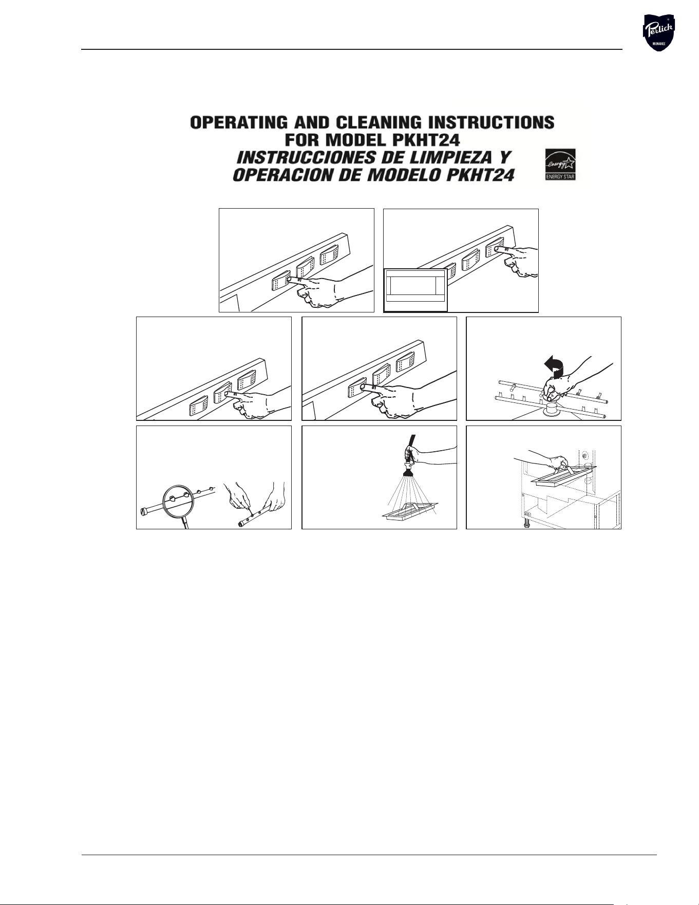
Commercial Glasswasher Installation & Operation Manual - PKHT24A
PKHT24A.IO.1
Rev 4.23.25
A
A
DISHMACHINES
OPERATING AND CLEANING INSTRUCTIONS
FOR MODEL CMA-180UC-3
INSTRUCCIONES DE LIMPIEZA Y
OPERACION DE MODELO CMA-180UC-3
Drain machine by pressing drain
button.
Para vaciar la maqina: Oprima el
boton de drenaje.
If spray arms are clogged remove by
turning bearings counter clockwise.
Si los brazos de rociado se tapan,
sera necesario sacarlos
desenroscandolos para el lado
izquierdo
.
Inspect top and bottom spray arm jets daily.
Use toothpick and push trash into spray
arm. Remove end plugs and flush with water.
Use un palillo para abrir los orificios.
Destapar por las puntas, removiendo el
tapon y enjuagelos con agua.
CMA PN: 06265.15
CAUTION: DO NOT START until
wash temperature reads 160°.
No empiece el ciclo hasta que
la temperatura sea 160°.
Hand remove and
thoroughly clean scrap
screen under faucet or
Pre-Rinse
Hose every
shift.
Remueva el
filtro de el interior de
el tanque de
desperdicios. Lave el
filtro con el rociador
de agua cada turno.
Replace all scrap screen back
into position.
Regrese el
filtro a su
lugar.
Start machine by pushing start button.
Para empezar la maquina,
cierre la puerta y
oprima el boton
de encendido.
3
5
Turn off power.
4
Apague La Maquina
6
7 8
2
1
O
F
WASH TEMP 160
0
160
O
Turn on power and machine will fill
automatically to correct level.
Prenda la maquina y automaticamente va
a llenar al nivel correcto.
12
Commercial Glasswasher Installation & Operation Manual - PKHT24A
A
160°F
24 psi.
160°F

Commercial Glasswasher Installation & Operation Manual - PKHT24A
PKHT24A.IO.1
Rev 4.23.25
Quick Service Guide
TECHNICAL ISSUE CAUSE SOLUTION
Door leaks
Machine is not level or is leaning forward Adjust machine legs to level
Wash arm end cap is missing Replace end cap
Door gasket issue Replace gasket
Thermometer failure
Loose wire at display, board or transformer Secure connectors
Faulty temperature sensing wire Correct, replace
Faulty temperature sending unit Replace unit
Faulty transformer Replace transformer
Scaled heating element Clean scale from heater
Rinse water temperature too low/
high
Booster heater’s thermostat not properly set Adjust thermostat
Incoming water temperature to booster heater
below 140 F
Adjust external water heater in
the facility
Pump motor not running
Loose lead connections Check and crimp connectors
Faulty #3 micro switch Replace micro switch
Faulty contactor Replace contactor
Faulty wash pump motor Replace wash pump motor
Pump motor runs continuously
Faulty #3 micro switch Replace micro switch
Faulty contactor Replace contactor
Low water pressure in the nal
rinse
Water regulator not adjusted properly Adjust regulator to 18-20 psi
Clogged nal rinse spray jets Clean jets
Missing nal rinse spray end cap Replace end cap
Low incoming water pressure from facility Increase pressure to 18-20 psi
Scrap trap overows overnight Faulty water solenoid diaphragm Clean or replace diaphragm
Poor cleaning results
Low wash or rinse water temperature Check temperature settings
Wash arm bearing or jets Clean bearing and arm jets
Rinse arm bearing or jets Clean bearing and arm jets
Tank discharge screen dirty Clean screen
Wash tank will not drain
Drain valve not operating Check power to drain valve
Drain valve faulty Replace drain valve

14
Commercial Glasswasher Installation & Operation Manual - PKHT24A
Troubleshooting
TECHNICAL ISSUE CAUSE SOLUTION
Machine inoperative
Power o at circuit breaker Reset circuit breaker
Defective power switch Replace power switch
Motor inoperative
Door is open Close door
Control panel is pulled out Secure control panel
Defective reed switch Replace reed switch
Defective timer assembly Replace timer assembly*
Defective pump motor contactor Replace contactor
Defective motor Replace motor
Motor runs with door open
Defective reed switch Replace reed switch
Defective pump motor contactor Replace contactor
Heater - No heat
High limit switch opened or defective Reset or replace switch
Defective thermostat Replace thermostat
Defective heater contactor Replace heater contactor
Defective heater Replace heater
Heater - Keeps running
Defective thermostat Replace thermostat
Defective heater contactor Replace heater contactor
Low heat during operation
Low incoming water temperature (below 140 F)
Turn up supply water heater or
insulate supply water pipe
Thermostat out of adjustment Adjust thermostat
Cold water mixing with supply
Isolate hot water from cold
water
Defective heater Replace heater
Low rinse water pressure
Pressure regulator out of adjustment Adjust pressure regulator
Defective pressure gauge (actual pressure
is ne)
Replace pressure gauge
Regulator at maximum but rinse
pressure still low
Insucient water supply Supply larger supply line
Defective water solenoid valve Replace water solenoid valve
Low rinse water ow
Low rinse water pressure
See “Low rinse water pressure”
in TECHNICAL ISSUE column
Rinse arm spray nozzles are limed De-lime rinse arm spray nozzles
No rinse water ow
Defective water solenoid valve Replace water solenoid valve
Defective (Rinse Relay) ice cube relay Replace ice cube relay
Rinse water runs with door open Defective reed switch Replace reed switch
* The timer assembly motor or micro switches can be replaced independently
if those are the only components that have failed.

Commercial Glasswasher Installation & Operation Manual - PKHT24A
PKHT24A.IO.1
Rev 4.23.25
Troubleshooting
TECHNICAL ISSUE CAUSE SOLUTION
With power on, activating start
switch does not begin cycle
Defective start switch (cycle light will not light
either)
Replace start switch
Defective timer assembly Replace timer assembly*
Start switch requires > 1 second
activation to run cycle
Defective (Instant Start) ice cube relay Replace ice cube relay
Activating fill switch does not
fill machine
Defective drain/ll switch Replace drain/ll switch
Defective water solenoid valve Replace water solenoid valve
Fill (rinse water) won’t shut o
Defective water solenoid valve Replace water solenoid valve
Defective drain/ll switch Replace drain/ll switch
Defective timer assembly Replace timer assembly*
Defective (Rinse Relay) ice cube relay Replace ice cube relay
Activating drain switch does not
drain machine
Drain hose is kinked Un-kink drain hose
Defective drain/ll switch Replace drain/ll
Cycle light does not light while
cycle runs
Defective cycle light Replace cycle light (green)
Power light does not light but
machine runs
Defective power light Replace power light (red)
Wash tank or nal rinse tempera-
ture does not display
Defective digital thermometer Replace digital thermometer
Both the wash tank temperature
and the nal rinse temperature do
not display
Defective thermometer transformer
Replace thermometer
transformer
Wash tank or nal rinse displays
wrong temperature
Defective digital thermometer Replace digital thermometer
Defective thermister Replace thermister
* The timer assembly motor or micro switches can be replaced independently
if those are the only components that have failed.

16
Commercial Glasswasher Installation & Operation Manual - PKHT24A
Parts Kit
PARTS KIT
P/N DESCRIPTION Qty.
15504.00 Motor Contactor, 2-Pole 20 Amp 1
15504.50 Heater Contactor, 2-Pole 35 Amp 1
00501.00 2 Minute Timer Motor 1
00631.00 Ice Cube Relay 120V 1
00707.00 1/2 Water Solenoid Repair Kit J/E 1
00738.15 Solenoid Coil JE 220V 1
15523.00 Rocker Switch Start Momentary 1
15523.50 Rocker Switch Drain/Fill 1
15524.00 Rocker Switch Power Maintained 1
00556.10 Reed Switch 1
03623.00 1/2" Vacuum Breaker Repair Kit - Watts 1
00707.00 1/2" Water Solenoid Repair Kit - JE 1
04113.00 L1X/L1-C Drain Valve 120V 1
00206.70 Pump Seal Kit 1
13417.89 Heater Thermostat 1
17523.60 High Limit Switch 200F 1
00411.00 Microswitch 1
03203.01 Dual Temperature Display Kit 1
00738.15 Solenoid Coil JE 115V/60Hz 1

Commercial Glasswasher Installation & Operation Manual - PKHT24A
PKHT24A.IO.1
Rev 4.23.25
PKHT24 Installation Guidelines
CUSTOMER NOTICE
Improper installation of this product may void the warranty on this machine. Please follow these
guidelines for recommended installation and to ensure the warranty of this model is applicable.
Glasswasher Installation Requirements
1. Machine must be level. Adjust leveling feet to accommodate uneven oor surfaces.
2. Drain height should not exceed maximum height of 16”. Connect supplied drain line to three-way
valve on back of machine and gravity feed to the oor drain.
3. PRV must be adjusted to not exceed 20 psi.
4. Water supply to machine must be a minimum 110°F.
5. A four-wire, (neutral, ground and two 110v lines) 220v single phase connection is required. There is
a six-foot cord provided with the machine. We recommend a minimum 50-amp dedicated circuit, but
you should consult your local building code requirements for proper breaker size.
Activating/Adjusting the Booster Heater
1. Booster heater must be lled with water prior to connecting the blue wire from high limit switch. The
high limit switch can be found by removing the front panel and locating the red button on the front of
the heater tank.
2. Once the booster heater has been connected, the thermostat should be adjusted to maintain
180°F during the nal rinse cycle. The thermostat is located on the front of the booster tank and is
accessible by removing the front panel on the machine.
Automatic Dispensing Equipment
1. Applications utilizing automated dispensers for administering ware wash chemicals must use
110v dispenser equipment. There is a 110v power block for installing this equipment inside the
control panel.
18
Commercial Glasswasher Installation & Operation Manual - PKHT24A
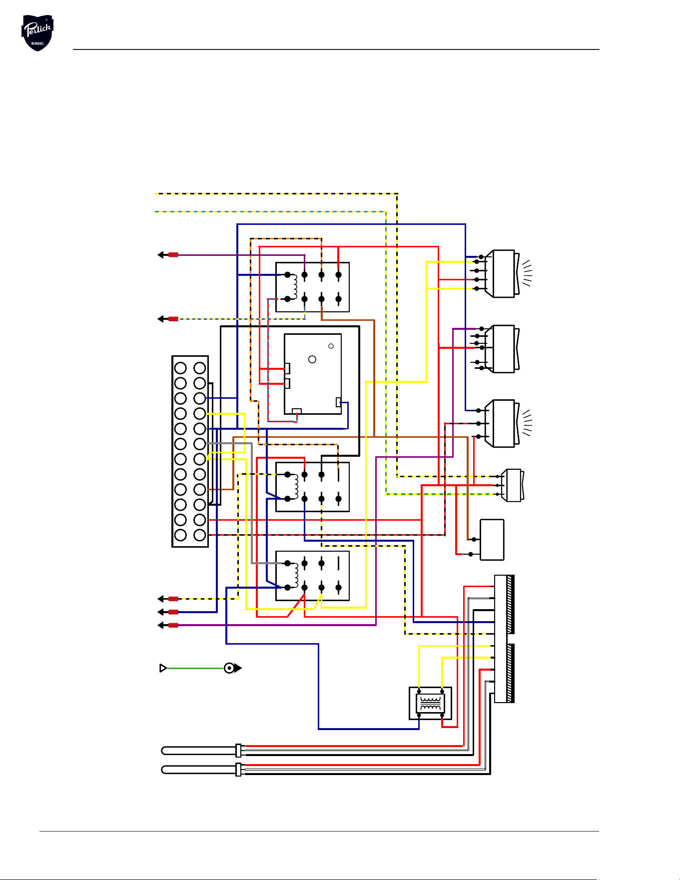
Electrical Diagram
PKHT24A Control Drawer
2
34
56
7
8
1
NC
NO
C
8
2
34
56
7
8
1 NC
NO
C
2
34
56
7
8
1
NC
NO
C
RELAY
FILL & DRAIN
FILL TIMER
FILL & RINSE
RELAY
START RELAY
DIGITAL THERMOMETER
TRANSFORMER 220V/12V
WASH TANK
THERMOMETER
FINAL RINSE
THERMOMETER DETERGENTRINSE
POWER DRAIN START
PRIME SWITCH
SAFETY
SWITCH
TEMPERATURE
SENSORS
J7 J6 J5 J1 J2 J3 J4 J10 J9 J8
DRAIN PUMP
RINSE
110 VAC
FILL/DRAIN
LEVEL SENSOR
DETERGENT
RUN SIGNAL
START SWITCH
DOOR SAFETY SWITCH
WATER SOLENOID
110 VAC SWITCHED
110 VAC
UPPER
COMPONENT TRAY
GROUND
DETERGENT
RINSE ADDITIVE
180UC-3 CONTROL DRAWER
Black W/ Yellow Stripe
Yellow W/ Black Stripe
3
11 1
RINSE
Commercial Glasswasher Installation & Operation Manual - PKHT24A
PKHT24A.IO.1
Rev 4.23.25
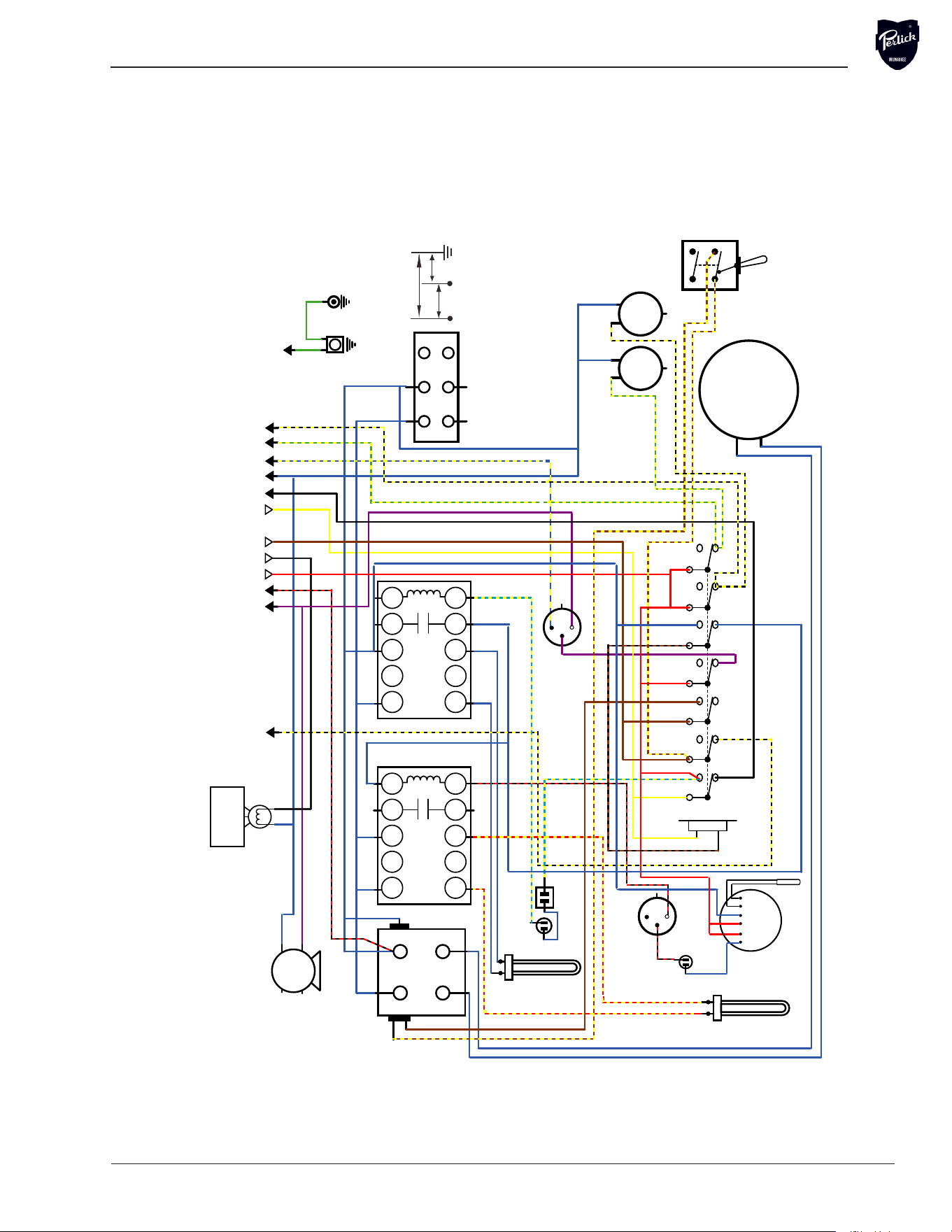
Electrical Diagram
N/C
L1 L2 L3
T3 22
21
A2
A1
T2T1
N/C
L1 L2 L3
T3 22
21
A2
A1
T2T1
WATER TANK
HEATER
THERMOSTAT
THERMOSTAT
WASH TANK
OVERLOAD
SWITCH
BOOSTER
HEATER
WASH PUMP
CONTACTOR
WATER
SOLENOID
VALVE
DRAIN
PUMP
HEATER
CONTACTOR
BOOSTER
HEATER
CONTACTOR
RINSE RELAY
DRAIN SWITCH
TO FILL
RELAY
RUN SIGNAL
START SWITCH
DOOR SAFETY SWITCH
WATER SOLENOID
110V V AC SWITCHED
110 V AC
110 V AC
DETERGENT
TO UPPER
COMPONENT TRAY
CHASSIS GROUND
POWER BLOCK
DELIME
NORMAL
FILL
DETERGENT
RINSE
START
RINSE
WASH
DRAIN PUMP
DET
RINSE
PUMP MOTOR
GROUND
RINSE
L1 L2
CMA 180UC-3 ELECTRICAL DIAGRAM
POWER BOX
WASH HEATER
PRESSURE
SWITCH
OVERLOAD
SWITCH
1 2
3
1
2
3
FILL / DRAIN
PRESSURE
SWITCH
RINSE
DRAIN
SAF T TEMP
2
2
0
0
8
8
-
-
2
2
4
4
0
0
V
V
L
L
1
1
L
L
2
2
G
G
1
1
2
2
0
0
V
V
1
1
2
2
0
0
V
V
PKHT24A Power Box

Form No. Z2346
Rev. 5.9.25