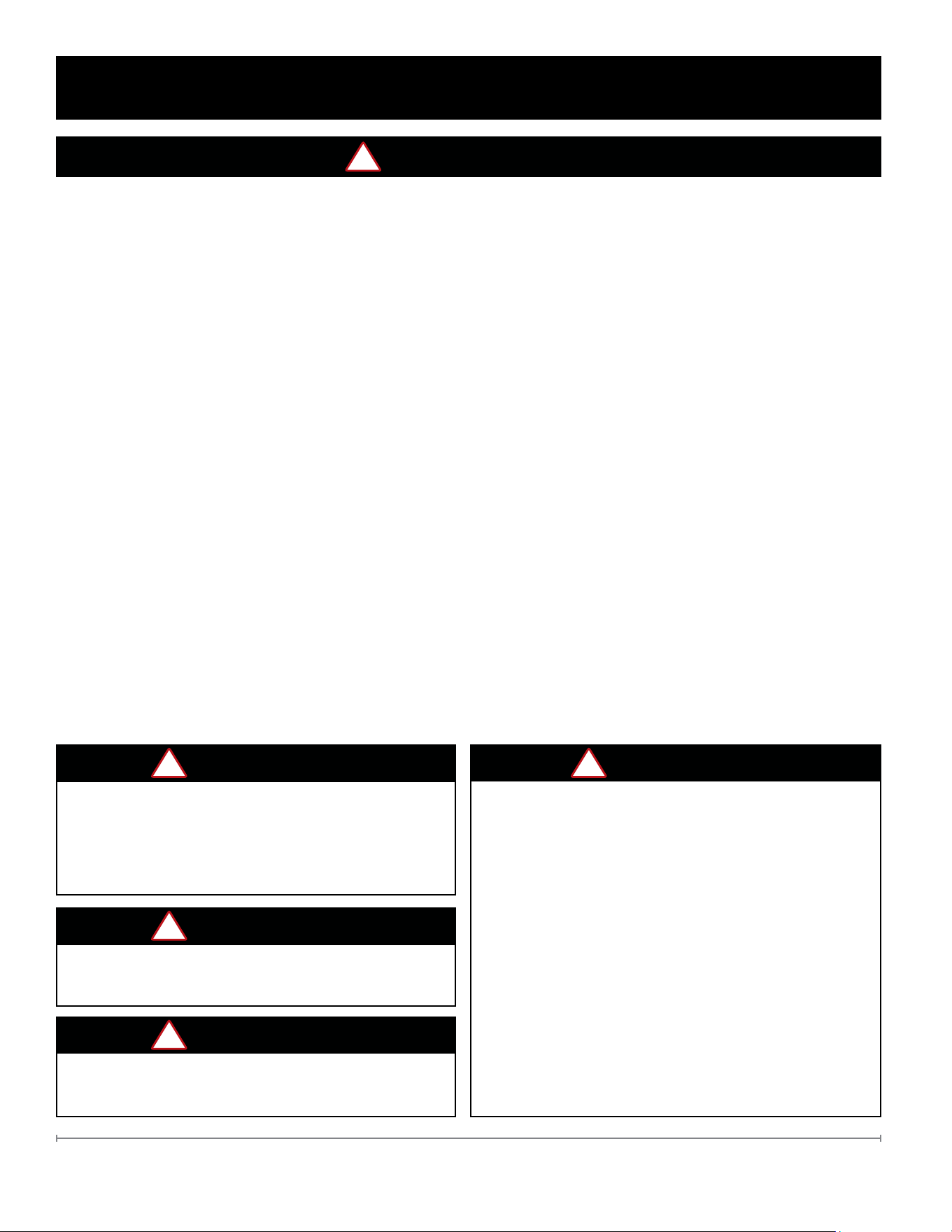
HOT GLASS WILL
CAUSE BURNS.
DO NOT TOUCH GLASS
UNTIL COOLED.
NEVER ALLOW CHILDREN
TO TOUCH GLASS.
A barrier designed to reduce the risk of burns from
the hot viewing glass is provided with this appliance
and shall be installed for the protection of children
and other-at risk individuals.
DANGER
HOT GLASS WILL
CAUSE BURNS.
DO NOT TOUCH GLASS
UNTIL COOLED.
NEVER ALLOW CHILDREN
TO TOUCH GLASS.
A barrier designed to reduce the risk of burns from
the hot viewing glass is provided with this appliance
and shall be installed for the protection of children
and other-at risk individuals.
DANGER
HOT GLASS WILL
CAUSE BURNS.
DO NOT TOUCH GLASS
UNTIL COOLED.
NEVER ALLOW CHILDREN
TO TOUCH GLASS.
A barrier designed to reduce the risk of burns from
the hot viewing glass is provided with this appliance
and shall be installed for the protection of children
and other-at risk individuals.
DANGER

2
Table of Contents
SAFETY INFORMATION ............................................................................... 4
Fireplace Information ................................................................................ 7
UL Certication ..................................................................................... 7
Fireplace Information ................................................................................ 8
Installation Information. . . . . . . . . . . . . . . . . . . . . . . . . . . . . . . . . . . . . . . . . . . . . . . . . . . . . . . . . . . . . . . . . . . . . . . . . . . 8
Maintenance Log ............................................................................... 9
Label ....................................................................................... 10
Technical Dimensions FMG3326F .................................................................. 11
Technical Dimensions FMG3726L .................................................................. 12
Technical Dimensions FMG3726R .................................................................. 13
Technical Dimensions FMG4126B .................................................................. 14
Technical Dimensions FMG4326F .................................................................. 15
Technical Dimensions FMG4726L .................................................................. 16
Technical Dimensions FMG4726R .................................................................. 17
Technical Dimensions FMG5126B .................................................................. 18
Gas Fireplace Operation ............................................................................. 19
Remote Control Instructions ...................................................................... 19
Receiver and Remote Batteries ................................................................... 24
Pairing Remote with Fireplace Receiver ............................................................. 24
Installation Steps. . . . . . . . . . . . . . . . . . . . . . . . . . . . . . . . . . . . . . . . . . . . . . . . . . . . . . . . . . . . . . . . . . . . . . . . . . . . . . . . . . . 25
Installation Preparation .............................................................................. 26
Fireplace Unpacking and Contents ................................................................. 26
Fireplace Positioning ........................................................................... 23
Vent Termination ................................................................................... 28
Instructions .................................................................................. 28
Vent Size .................................................................................... 28
Minimum Combustible Clearances from Vent ......................................................... 29
Minimum Clearances to Vent Termination ........................................................... 30
Unit Installation with Horizontal Termination .......................................................... 31
Unit Installation with Vertical Termination ............................................................ 33
Minimum Venting Requirements - Natural Gas ........................................................ 35
Chase and Framing Installation and Planning .............................................................. 39
Clearances ....................................................................................... 42
Material Specications .......................................................................... 42
Minimum Combustible Clearances from Vent Pipe ..................................................... 43
Chase Clearances ............................................................................. 44
Additional Clearances .......................................................................... 45
Mantel Clearance .............................................................................. 46
Clearance to Sprinkler .......................................................................... 46
Finishing Around Front of the Fireplace ............................................................. 47

3
FaberFires.com
Heat Releases and Air Intakes ......................................................................... 48
Heat Releases ................................................................................ 48
Air Intake .................................................................................... 48
Examples of Heat Releases and Air Intakes ........................................................... 49
Television Mounting Information ....................................................................... 50
Flat with Recessed TV .......................................................................... 51
Recessed with recessed TV ...................................................................... 51
Television Install Flush Above Fireplace ............................................................. 52
Television Install Without Recess .................................................................. 52
Gas Installation .................................................................................... 53
General ..................................................................................... 53
Gas Valve. . . . . . . . . . . . . . . . . . . . . . . . . . . . . . . . . . . . . . . . . . . . . . . . . . . . . . . . . . . . . . . . . . . . . . . . . . . . . . . . . . . . 54
Accessing the Gas Valve and Electronic Receiver ...................................................... 54
Installation at High Altitude ...................................................................... 55
Gas Valve Access Door ......................................................................... 55
Commonwealth of Massachusetts ................................................................. 56
Electric and Control ................................................................................ 57
Wiring Diagram ............................................................................... 57
Power Source ................................................................................ 57
Wall Switch - Optional .......................................................................... 58
Final Installation ................................................................................... 59
Media Arrangement ............................................................................ 59
Sealing the glass .............................................................................. 64
Feature Removal ................................................................................... 65
Safety Screen Removal ......................................................................... 65
Glass Removal ................................................................................ 66
Replacement Parts ................................................................................. 67
Maintenance ...................................................................................... 68
Maintenance Instructions ........................................................................ 68
Yearly Service ................................................................................ 69
Flame Pattern ................................................................................ 70
Log Replacement .............................................................................. 71
Glass Gasket ................................................................................. 71
Glass ....................................................................................... 71
Glass Replacement ............................................................................ 72
General Vent Maintenance ....................................................................... 72
Troubleshooting Guide .............................................................................. 73
Warranty ......................................................................................... 75
Table of Contents

4
SAFETY INFORMATION
!
WARNING
• Due to high temperatures, the appliance should be
located out of trac and away from furniture and
draperies.
• Furniture or other objects must be kept a minimum of
3 feet (0.92 m) away from the front of the appliance.
• Ensure you have incorporated adequate safety
measure to protect infants/toddlers from touching hot
surfaces.
• Even after the appliance is o, it will remain hot for an
extended period of time.
• Check with your local hearth specialty dealer for
safety screens and hearth guards to protect children
from hot surfaces.
• Any safety screen, guard or barrier removed for
servicing the appliance, must be replaced prior to
operating the appliance.
• The appliance area must be kept clear and free from
combustible materials, gasoline and other ammable
vapors and liquids.
• If the appliance shuts o, do not relight until you
provide fresh air. If appliance keeps shutting o, have
it serviced. Keep burner and control compartment
clean.
• Under no circumstances should this appliance be
modied.
• Do not allow wind or fans to blow directly into the
appliance. Avoid any drafts that alter burner ame
patterns.
• Do not use a blower insert, heat exchanger insert
or other accessory not approved for use with this
appliance.
• This appliance must not be connected to a chimney
ue pipe serving a separate solid fuel burning
appliance.
• Do not use this appliance if any part has been under
water. Immediately call a qualied service technician
to inspect the appliance and to replace any part of the
control system and any gas control which has been
under water.
• Do not operate the appliance with the glass removed,
cracked, or broken. Replacement of the glass should
be done by a licensed or qualied service person if
equipped.
• This appliance is hot when operated and can cause
severe burns if contacted.
• Any changes or alterations to this appliance or its
controls can be dangerous and is prohibited.
• Do not operate appliance before reading and
understanding operating instructions. Failure to
operate appliance according to operating instructions
could cause re or injury.
• Risk of re or asphyxiation. Do not operate appliance
with xed glass removed and never obstruct the front
opening of the appliance.
• Risk of burns. The appliance should be turned o and
cooled before servicing.
• Do not install damaged, incomplete or substitute
components.
• Risk of cuts and abrasions. Wear protective gloves,
protective footwear, and safety glasses during
installation. Sheet metal edges may be sharp.
• Do not burn wood or other materials in this appliance.
• Provide adequate ventilation and combustion air.
Provide adequate accessibility clearance for servicing
and operating the appliance.
• High pressure will damage valve. Disconnect gas
supply piping before pressure testing gas line at test
pressures above 1/2 PSIG. Close the manual shuto
valve before pressure testing gas line at test pressures
equal to or less than 1/2 PSIG (35 mb).
• The appliance must not be operated at temperatures
below freezing (0°C / 32°F).
• Children and adults should be alerted to hazards of
high surface temperature and should stay away to
avoid burns or clothing ignition.
• Young children should be carefully supervised when
they are in the same room as the appliance. Toddlers,
young children and others may be susceptible
to accidental contact burns. A physical barrier is
recommended if there are at risk individuals in the
house. To restrict access to an appliance or stove,
install an adjustable safety gate to keep toddlers,
young children, and other at risk individuals out of the
room and away from hot surfaces.
• Clothing or other ammable material should not be
placed on or near the appliance.
5
FaberFires.com
The direct vent system appliance must be installed
as an OEM installation in manufactured homes
(USA only) or an aftermarket permanently located,
or a mobile home where not prohibited by local
codes and must be installed in accordance with
Manufacturer’s instructions and the Manufactured
Home Construction and Safety Standard, Title24
CFR, Part3280 in the United States, or the Standard
for Installation in Mobile Homes CAN/CSAZ240 MH
Series in Canada.
This appliance is only for use with the type(s) of gas
indicated on the rating plate.
This product is listed to ANSI standards for ANSI
Z21.88/CSA 2.33-2019 - Vented Gas Fireplace
Heaters Fireplaces CSA2.17-2017 Gas-Fired
Appliance for Use at High Altitudes - Fourth Edition.
SAFETY INFORMATION
• Only optional fronts certied with the appliance are to
be installed on the appliance.
• Keep the packaging material out of reach of children
and dispose of the material in a safe manner. As with
all plastic bags, these are not toys and should be kept
away from children and infants.
• If equipped, the screen must be in place (closed)
when the appliance is in operation.
• When equipped with pressure relief doors, they must
be kept closed while the appliance is operating to
prevent exhaust fumes containing carbon monoxide,
from entering the home. Temperatures of the exhaust
escaping through these openings can also cause the
surrounding combustible materials to overheat and
catch re.
• Carbon monoxide poisoning may lead to death; early
signs of carbon monoxide poisoning resemble the
u, with headache, dizziness and/or nausea. If you
have these signs, the appliance may not be working
properly. Get fresh air at once! Have appliance
serviced. Some people; pregnant women, persons
with heart or lung disease, anemia, those under the
inuence of alcohol, those at high altitudes are more
aected by carbon monoxide than others. Failure to
keep the primary air opening(s) of the burner(s) clean
may result in sooting and property damage.
• As with any combustion appliance, we recommend
having your appliance regularly inspected and serviced
as well as having a Carbon Monoxide Detector
installed in the same area to defend you and your
family against Carbon Monoxide Poisoning (not
applicable for outdoor appliances).
• Ensure clearances to combustibles are maintained
when building a mantel or shelves above the
appliance. Elevated temperatures on the wall or
in the air above the appliance can cause melting,
discoloration or damage to decorations, a TV or other
electronic components.
• For appliances equipped with a safety barrier; if
the barrier becomes damaged, the barrier shall be
replaced with the manufacturer’s barrier for this
appliance.
• Installation and repair should be done by a qualied
service person. The appliance and its venting
system should be inspected before use and at least
annually by a qualied service person. More frequent
cleaning may be required due to excessive lint from
carpeting, bedding material, etc. It is imperative that
control compartments, burners and circulating air
passageways of the appliance be kept clean.
!
WARNING
Failure to install this appliance correctly will void
your warranty and may cause a serious house re.
!
WARNING
!
WARNING
!
WARNING
!
WARNING
Never leave children or other at-risk individuals
alone with the appliance.
These direct vent replaces must be electrically
grounded in accordance with the local codes or, in
the absence of local codes, with National Electric
code, ANSI/NFPA 70, or the Canadian Electric
Code, CSA C22.1.
6
Faber requires installation be performed
by an NFI-certied installer or a certied
Faber installer. Installations that do not
follow this instruction will not be covered
by warranty or serviced.
We recommend removing the glass with the suction
cups supplied by the manufacturer. When glass is
cooled, lower the glass to rest in a safe place. This
is to prevent damage to the glass edges. Extra care
must be taken when removing/installing the glass.
Breakage or damage to the edge of the glass which
occurs as a result of careless handling will not be
covered under warranty.
Due to high temperatures, the appliance should be
located out of trac and away from furniture and
draperies.
Children and adults should be alerted to the hazards
of high surface temperature and should stay away
to avoid burns or clothing ignition.
This appliance must be electrically wired and
grounded in accordance with local codes, or in
the absence of local codes, with National Electric
Code ANSI/NFPA70-latest edition or the Canadian
Electric Code CSAC22.1. A 110–120 V AC circuit
for this product must be protected with ground-
fault circuit-interrupter protection, in compliance
with the applicable electrical codes, when it is
installed in locations such as in bathrooms or near
sinks.
CARBON MONOXIDE POISONING HAZARD
Failure to follow the steps outlined below for
each appliance connected to the venting system
being placed into operation could result in carbon
monoxide poisoning or death. The following steps
shall be followed for each appliance connected to
the venting system being placed into operation,
while all other appliances connected to the venting
system are not in operation:
1. Seal any unused openings in the venting system.
2. Inspect the venting system for proper size and
horizontal pitch, as required in the National Fuel
Gas Code, ANSI Z223.1/NFPA 54 or the National
Gas and Propane lnstallation Code, CSA B149.1
and these instructions. Determine that there is
no blockage or restriction, leakage, corrosion
and other deciencies which could cause an
unsafe condition.
3. As far as practical, close all building doors and
windows and all doors between the space in
which the appliance(s) connected to the venting
system are located and other spaces of the
building.
4. Close replace dampers.
5. Turn on clothes dryers and any appliance not
connected to the venting system. Turn on
any exhaust fans, such as range hoods and
bathroom exhausts, so they are operating at
maximum speed. Do not operate a summer
exhaust fan.
6. Follow the lighting instructions. Place the
appliance being inspected into operation.
Adjust the thermostat so appliance Is operating
continuously.
7. Test for spillage from draft hood equipped
appliances at the draft hood relief opening after
5 minutes of main burner operation. Use the
ame of a match or candle.
8. If improper venting Is observed during any of
the above tests, the venting system must be
corrected in accordance with National Fuel Gas
Code, ANSI2223.1/NFPA and/or Natural Gas
and Propane Installation Code, CSA B149.1.
9. After it has been determined that each appliance
connected to the venting system properly vents
when tested as outlined above, return doors,
windows, exhaust fans, replace dampers and
any other gas-red burning appliances to their
previous conditions of use.
!
WARNING
!
WARNING
!
WARNING

7
FaberFires.com
With 175 years of craftsmanship, innovations, a visionary outlook and our passion, we have become the
expert in res. Faber is responsible for inventions that have become standard around the world, and they are
our pride and passion!
The re makers of Faber develop the most beautiful ambient res. However, that passion goes beyond the
re, its connective and calming eect is just as important to us. We want you to enjoy atmosphere and
cosiness together with your friends and family.
All our replaces are tested and have been certied to meet stringent CSA
guidelines, ensuring optimum quality, safety and eciency.
Certication Information:
ANSI Z21.88/CSA 2.33-2019 - Vented Gas Fireplace Heaters
CSA2.17-2017 - Gas-Fired Appliances for Use at High Altitudes
Fireplace Information
UL Certication
INSTALLER : Leave this manual with the appliance.
CONSUMER: Retain this manual for future reference.
This manual should be used for following Faber Matrix models:
FMG3326F FMG4326F
FMG3726L FMG4726L
FMG3726R FMG4726R
FMG4126B FMG5126B
• All models share the same gas valve system, remote, gas connection, and glass type, simplifying
installation and operation.
• All warnings and instructions apply to all models.
• Refer to the model name for specic model, clearance, and installation information.
• Faber Fireplaces should only be connected to M&G DuraVent 5x8 venting systems.
Refer to the specic appliance model and size to determine vent size and chimney pathway requirements.
• This product is listed to ANSI standards for ‟Vented Gas Fireplace Heaters” and applicable sections of
‟Gas Burning Heating Appliances for Manufactured Homes and Recreational Vehicles”, and ‟Gas Fired
Appliances for Use at High Altitudes” Fourth Edition.

8
Unit Information
Model Number
Serial Number
Owner Information
Name
Address
Technician Information
Name
Company
Technician NPI #
Notes
IMPORTANT The following must be completed by the qualied installer and be left with the owner of the
property. The model and serial number of the unit can be found on the label axed to the replace.
Installation Information
9
FaberFires.com
Fireplace Information
Maintenance Log
Service Date Notes
10
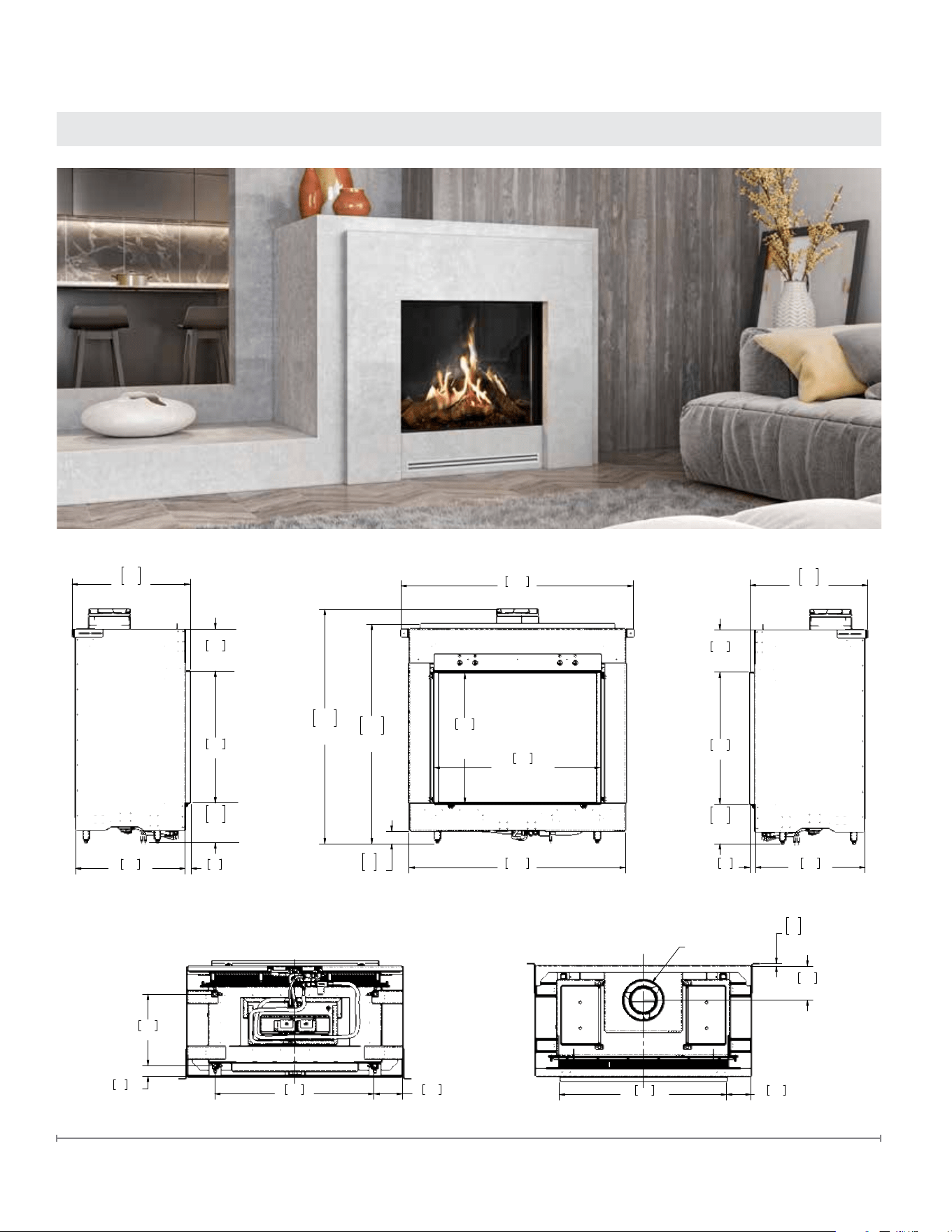
Label
Outer bottom trim and screen
must be removed to access
the label, which is attached
by a chain and located in a
dedicated slot under the grate
in the location shown above.
11
FaberFires.com
Fireplace Information
825
32 7/16"
VIEWING AREA
645
25 3/8"
VIEWING
AREA
1073
42 1/4"
1110
1089
43 11/16"
42 7/8"
82
62
3 1/4"
2 7/16"
1153
45 3/8"
1183
1163
46 5/8"
45 13/16"
830
32 11/16"
51
0
2"
0"
169
6 5/8"
122
4 13/16"
DURAVENT 5" x 8"
218
198
8 9/16"
7 3/4"
654
25 3/4"
622
571
24 1/2"
22 1/2"
545
21 7/16"
26
1 1/16"
209
8 1/4"
790
31 1/8"
354
13 15/16"
53
2 1/16"
141
5 9/16"
218
198
8 9/16"
7 3/4"
654
25 3/4"
622
571
24 1/2"
22 1/2"
545
21 7/16"
26
1 1/16"
209
8 1/4"
LEFT SIDE FRONT
TOP VIEWBOTTOM VIEW
RIGHT SIDE
FMG3326F - Front-facing Built-in Gas Fireplace
Technical Dimensions
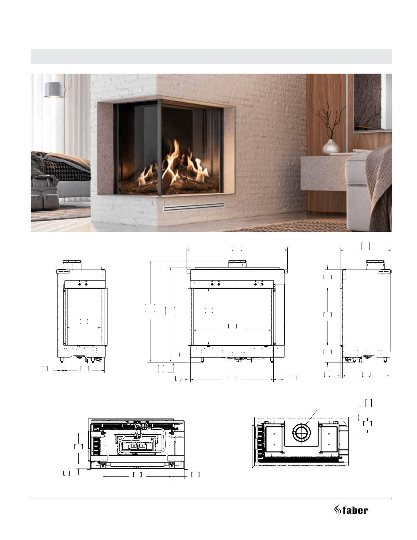
12
896
35 1/4"
VIEWING AREA
27
1 1/16"
952
37 7/16"
122
4 13/16"
82
62
3 1/4"
2 7/16"
1110
1089
43 11/16"
42 7/8"
1183
1163
46 5/8"
45 13/16"
645
25 3/8"
VIEWING
AREA
1153
45 3/8"
169
6 5/8"
51
0
2"
0"
DURAVENT 5" x 8"
622
571
24 1/2"
22 1/2"
545
21 7/16"
26
1 1/16"
198
7 3/4"
654
25 3/4"
209
8 1/4"
141
5 9/16"
790
31 1/8"
53
2 1/16"
354
13 15/16"
389
15 5/16"
VIEWING
AREA
458
18"
87
3 7/16"
LEFT SIDE FRONT
896
35 1/4"
VIEWING AREA
27
1 1/16"
952
37 7/16"
122
4 13/16"
82
62
3 1/4"
2 7/16"
1110
1089
43 11/16"
42 7/8"
1183
1163
46 5/8"
45 13/16"
645
25 3/8"
VIEWING
AREA
1153
45 3/8"
169
6 5/8"
51
0
2"
0"
DURAVENT 5" x 8"
622
571
24 1/2"
22 1/2"
545
21 7/16"
26
1 1/16"
198
7 3/4"
654
25 3/4"
209
8 1/4"
141
5 9/16"
790
31 1/8"
53
2 1/16"
354
13 15/16"
389
15 5/16"
VIEWING
AREA
458
18"
87
3 7/16"
TOP VIEW
BOTTOM VIEW
RIGHT SIDE
FMG3726L - Left-facing Built-in Gas Fireplace
Technical Dimensions
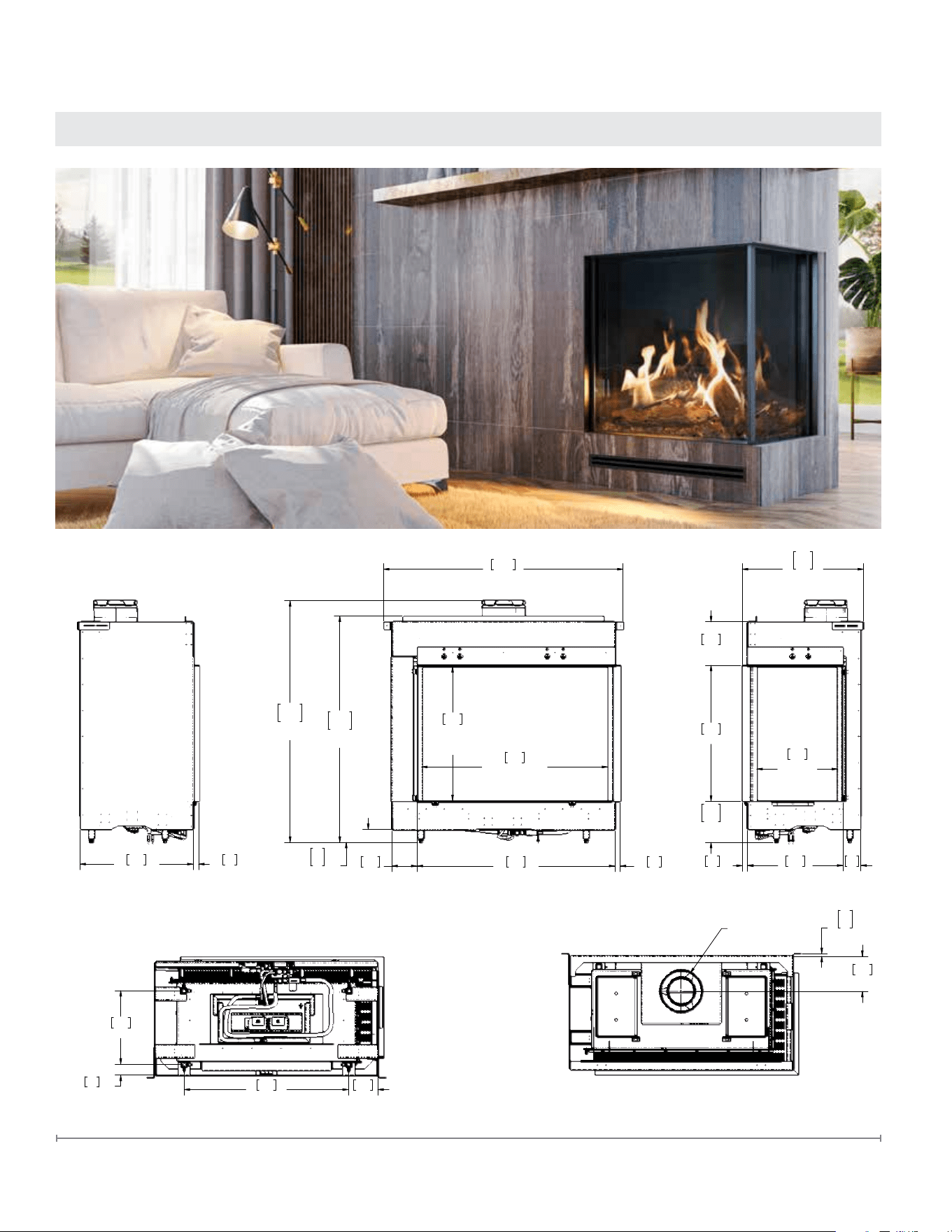
13
FaberFires.com
Fireplace Information
1153
45 3/8"
82
62
3 1/4"
2 7/16"
1183
1163
46 5/8"
45 13/16"
645
25 3/8"
VIEWING
AREA
896
35 1/4"
VIEWING AREA
27
1 1/16"
952
37 7/16"
122
4 13/16"
1110
1089
43 11/16"
42 7/8"
169
6 5/8"
51
0
2"
0"
DURAVENT 5" x 8"
389
15 5/16"
VIEWING
AREA
87
3 7/16"
458
18"
26
1 1/16"
622
571
24 1/2"
22 1/2"
209
8 1/4"
654
25 3/4"
218
198
8 9/16"
7 3/4"
141
5 9/16"
790
31 1/8"
53
2 1/16"
354
13 15/16"
545
21 7/16"
26
1 1/16"
LEFT SIDE FRONT
TOP VIEWBOTTOM VIEW (FEET LOCATION)
RIGHT SIDE
FMG3726R - Right-facing Built-in Gas Fireplace
Technical Dimensions
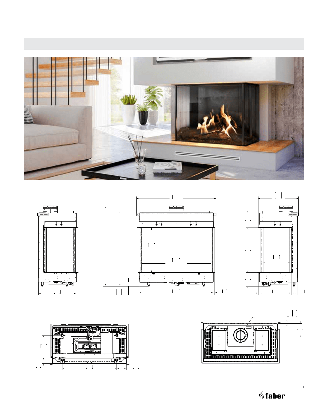
14
1007
39 5/8"
VIEWING AREA
82
62
3 1/4"
2 7/16"
1110
1089
43 11/16"
42 7/8"
1183
1163
46 5/8"
45 13/16"
1073
42 1/4"
21
13/16"
1153
45 3/8"
169
6 5/8"
51
0
2"
0"
DURAVENT 5" x 8"
90
3 9/16"
454
17 7/8"
26
1 1/16"
218
198
8 9/16"
7 3/4"
654
25 3/4"
209
8 1/4"
622
571
24 1/2"
22 1/2"
389
15 5/16"
VIEWING
AREA
141
5 9/16"
790
31 1/8"
354
13 15/16"
53
2 1/16"
545
21 7/16"
645
25 3/8"
VIEWING
AREA
LEFT SIDE FRONT
TOP VIEWBOTTOM VIEW (FEET LOCATION)
RIGHT SIDE
FMG4126B - Bay Built-in Gas Fireplace
Technical Dimensions
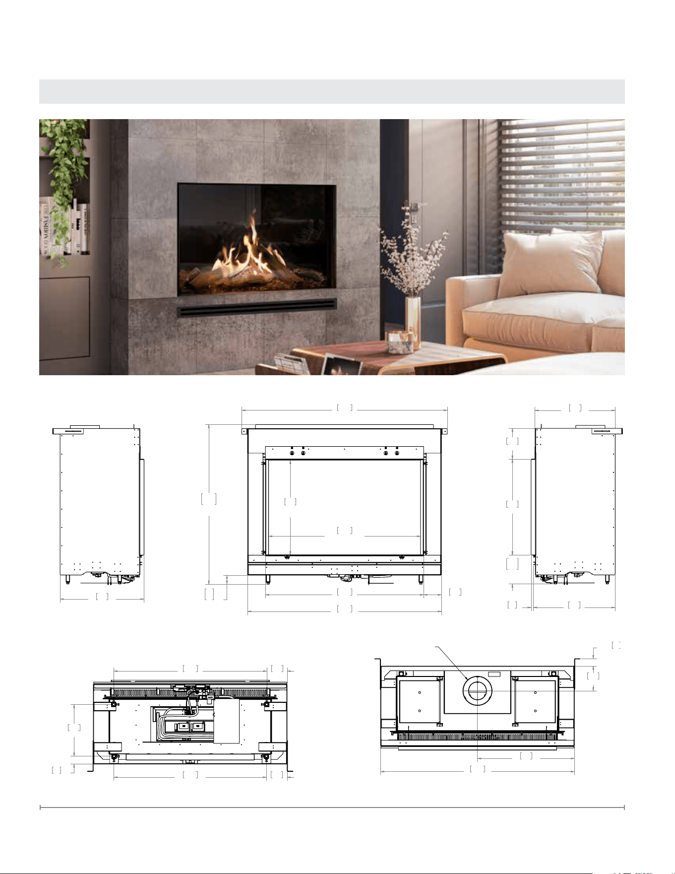
15
FaberFires.com
Fireplace Information
FMG4326F - Front-facing Built-in Gas Fireplace
Technical Dimensions
1036
40 13/16"
VIEWING AREA
1403
55 1/4"
1109
1089
43 11/16"
42 7/8"
645
25 3/8"
VIEWING AREA
82
62
3 3/16"
2 7/16"
122
4 13/16"
1080
42 1/2"
1323
52 1/16"
573
22 9/16"
209
8 1/4"
654
25 3/4"
558
22"
15
9/16"
547
21 9/16"
218
198
8 9/16"
7 3/4"
169
6 5/8"
662
26 1/16"
1323
52 1/16"
MIN.
51
2"
VENT 5" x 8"
1045
41 1/8"
139
5 1/2"
354
13 15/16"
53
2 1/16"
1040
40 15/16"
141
5 9/16"
BOTTOM VIEW (FEET LOCATION)
ISOMETRIC VIEW
FOR REFERENCE ONLY
1036
40 13/16"
VIEWING AREA
1403
55 1/4"
1109
1089
43 11/16"
42 7/8"
645
25 3/8"
VIEWING AREA
82
62
3 3/16"
2 7/16"
122
4 13/16"
1080
42 1/2"
1323
52 1/16"
573
22 9/16"
209
8 1/4"
654
25 3/4"
558
22"
15
9/16"
547
21 9/16"
218
198
8 9/16"
7 3/4"
169
6 5/8"
662
26 1/16"
1323
52 1/16"
MIN.
51
2"
VENT 5" x 8"
1045
41 1/8"
139
5 1/2"
354
13 15/16"
53
2 1/16"
1040
40 15/16"
141
5 9/16"
BOTTOM VIEW (FEET LOCATION)
ISOMETRIC VIEW
FOR REFERENCE ONLY
1036
40 13/16"
VIEWING AREA
1403
55 1/4"
1109
1089
43 11/16"
42 7/8"
645
25 3/8"
VIEWING AREA
82
62
3 3/16"
2 7/16"
122
4 13/16"
1080
42 1/2"
1323
52 1/16"
573
22 9/16"
209
8 1/4"
654
25 3/4"
558
22"
15
9/16"
547
21 9/16"
218
198
8 9/16"
7 3/4"
169
6 5/8"
662
26 1/16"
1323
52 1/16"
MIN.
51
2"
VENT 5" x 8"
1045
41 1/8"
139
5 1/2"
354
13 15/16"
53
2 1/16"
1040
40 15/16"
141
5 9/16"
BOTTOM VIEW (FEET LOCATION)
ISOMETRIC VIEW
FOR REFERENCE ONLY
1036
40 13/16"
VIEWING AREA
1403
55 1/4"
1109
1089
43 11/16"
42 7/8"
645
25 3/8"
VIEWING AREA
82
62
3 3/16"
2 7/16"
122
4 13/16"
1080
42 1/2"
1323
52 1/16"
573
22 9/16"
209
8 1/4"
654
25 3/4"
558
22"
15
9/16"
547
21 9/16"
218
198
8 9/16"
7 3/4"
169
6 5/8"
662
26 1/16"
1323
52 1/16"
MIN.
51
2"
VENT 5" x 8"
1045
41 1/8"
139
5 1/2"
354
13 15/16"
53
2 1/16"
1040
40 15/16"
141
5 9/16"
BOTTOM VIEW (FEET LOCATION)
ISOMETRIC VIEW
FOR REFERENCE ONLY
1036
40 13/16"
VIEWING AREA
1403
55 1/4"
1109
1089
43 11/16"
42 7/8"
645
25 3/8"
VIEWING AREA
82
62
3 3/16"
2 7/16"
122
4 13/16"
1080
42 1/2"
1323
52 1/16"
573
22 9/16"
209
8 1/4"
654
25 3/4"
558
22"
15
9/16"
547
21 9/16"
218
198
8 9/16"
7 3/4"
169
6 5/8"
662
26 1/16"
1323
52 1/16"
MIN.
51
2"
VENT 5" x 8"
1045
41 1/8"
139
5 1/2"
354
13 15/16"
53
2 1/16"
1040
40 15/16"
141
5 9/16"
BOTTOM VIEW (FEET LOCATION)
ISOMETRIC VIEW
FOR REFERENCE ONLY
LEFT SIDE FRONT
TOP VIEWBOTTOM VIEW (FEET LOCATION)
RIGHT SIDE
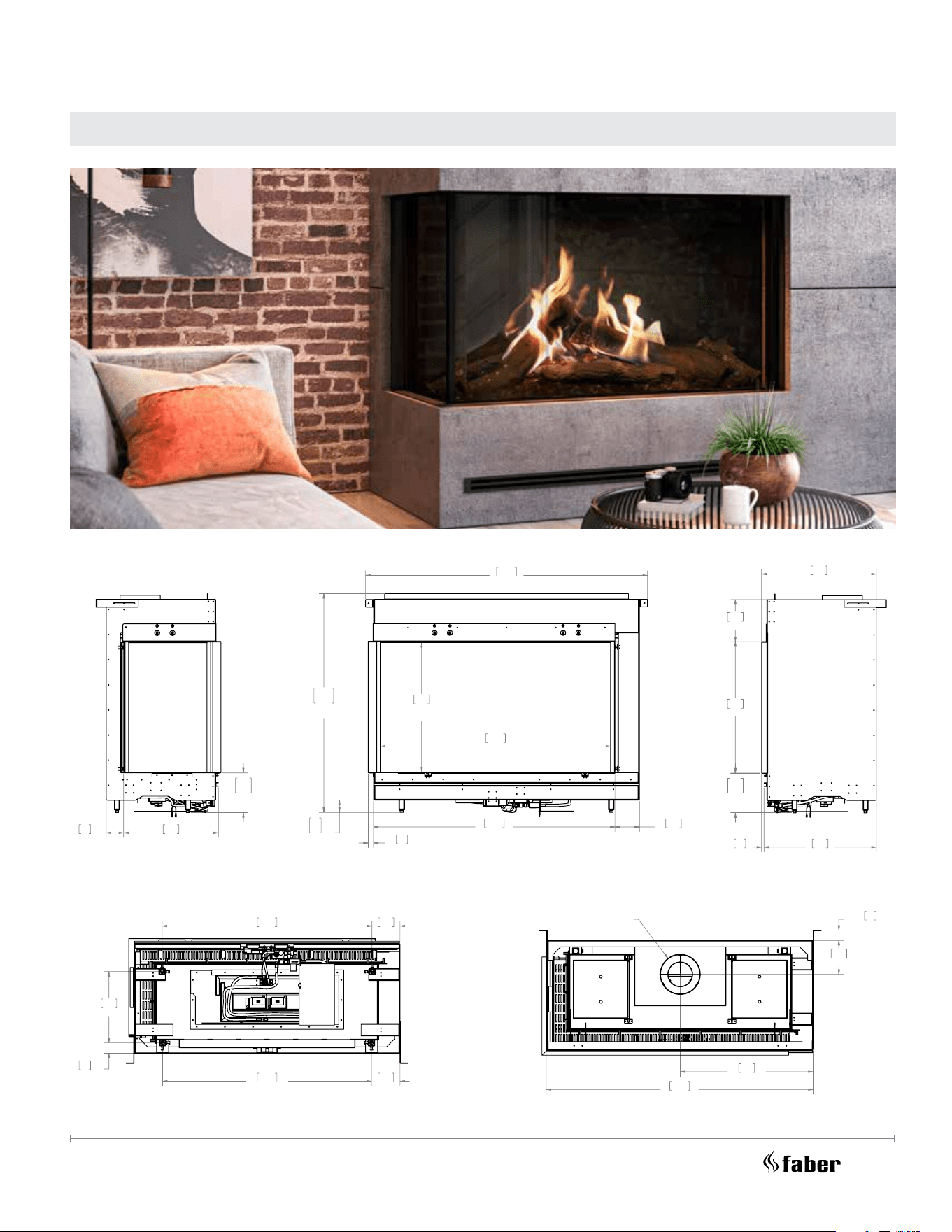
16
FMG4726L - Left-facing Built-in Gas Fireplace
Technical Dimensions
1403
55 1/4"
1109
1089
43 11/16"
42 7/8"
82
62
3 3/16"
2 7/16"
27
1 1/16"
645
25 3/8"
VIEWING AREA
1146
45 1/8"
VIEWING AREA
1202
47 5/16"
122
4 13/16"
218
198
8 9/16"
7 3/4"
472
18 9/16"
87
3 7/16"
209
8 1/4"
654
25 3/4"
558
22"
13
1/2"
571
22 1/2"
218
198
8 9/16"
7 3/4"
VENT 5" X 8"
MIN.
51
2"
169
6 5/8"
662
26 1/16"
1329
52 5/16"
354
13 15/16"
1045
41 1/8"
1040
40 15/16"
53
2 1/16"
141
5 9/16"
139
5 1/2"
ISOMETRIC VIEW
FOR REFERENCE ONLY
1403
55 1/4"
1109
1089
43 11/16"
42 7/8"
82
62
3 3/16"
2 7/16"
27
1 1/16"
645
25 3/8"
VIEWING AREA
1146
45 1/8"
VIEWING AREA
1202
47 5/16"
122
4 13/16"
218
198
8 9/16"
7 3/4"
472
18 9/16"
87
3 7/16"
209
8 1/4"
654
25 3/4"
558
22"
13
1/2"
571
22 1/2"
218
198
8 9/16"
7 3/4"
VENT 5" X 8"
MIN.
51
2"
169
6 5/8"
662
26 1/16"
1329
52 5/16"
354
13 15/16"
1045
41 1/8"
1040
40 15/16"
53
2 1/16"
141
5 9/16"
139
5 1/2"
ISOMETRIC VIEW
FOR REFERENCE ONLY
1403
55 1/4"
1109
1089
43 11/16"
42 7/8"
82
62
3 3/16"
2 7/16"
27
1 1/16"
645
25 3/8"
VIEWING AREA
1146
45 1/8"
VIEWING AREA
1202
47 5/16"
122
4 13/16"
218
198
8 9/16"
7 3/4"
472
18 9/16"
87
3 7/16"
209
8 1/4"
654
25 3/4"
558
22"
13
1/2"
571
22 1/2"
218
198
8 9/16"
7 3/4"
VENT 5" X 8"
MIN.
51
2"
169
6 5/8"
662
26 1/16"
1329
52 5/16"
354
13 15/16"
1045
41 1/8"
1040
40 15/16"
53
2 1/16"
141
5 9/16"
139
5 1/2"
ISOMETRIC VIEW
FOR REFERENCE ONLY
1403
55 1/4"
1109
1089
43 11/16"
42 7/8"
82
62
3 3/16"
2 7/16"
27
1 1/16"
645
25 3/8"
VIEWING AREA
1146
45 1/8"
VIEWING AREA
1202
47 5/16"
122
4 13/16"
218
198
8 9/16"
7 3/4"
472
18 9/16"
87
3 7/16"
209
8 1/4"
654
25 3/4"
558
22"
13
1/2"
571
22 1/2"
218
198
8 9/16"
7 3/4"
VENT 5" X 8"
MIN.
51
2"
169
6 5/8"
662
26 1/16"
1329
52 5/16"
354
13 15/16"
1045
41 1/8"
1040
40 15/16"
53
2 1/16"
141
5 9/16"
139
5 1/2"
ISOMETRIC VIEW
FOR REFERENCE ONLY
1403
55 1/4"
1109
1089
43 11/16"
42 7/8"
82
62
3 3/16"
2 7/16"
27
1 1/16"
645
25 3/8"
VIEWING AREA
1146
45 1/8"
VIEWING AREA
1202
47 5/16"
122
4 13/16"
218
198
8 9/16"
7 3/4"
472
18 9/16"
87
3 7/16"
209
8 1/4"
654
25 3/4"
558
22"
13
1/2"
571
22 1/2"
218
198
8 9/16"
7 3/4"
VENT 5" X 8"
MIN.
51
2"
169
6 5/8"
662
26 1/16"
1329
52 5/16"
354
13 15/16"
1045
41 1/8"
1040
40 15/16"
53
2 1/16"
141
5 9/16"
139
5 1/2"
ISOMETRIC VIEW
FOR REFERENCE ONLY
LEFT SIDE FRONT
TOP VIEWBOTTOM VIEW (FEET LOCATION)
RIGHT SIDE
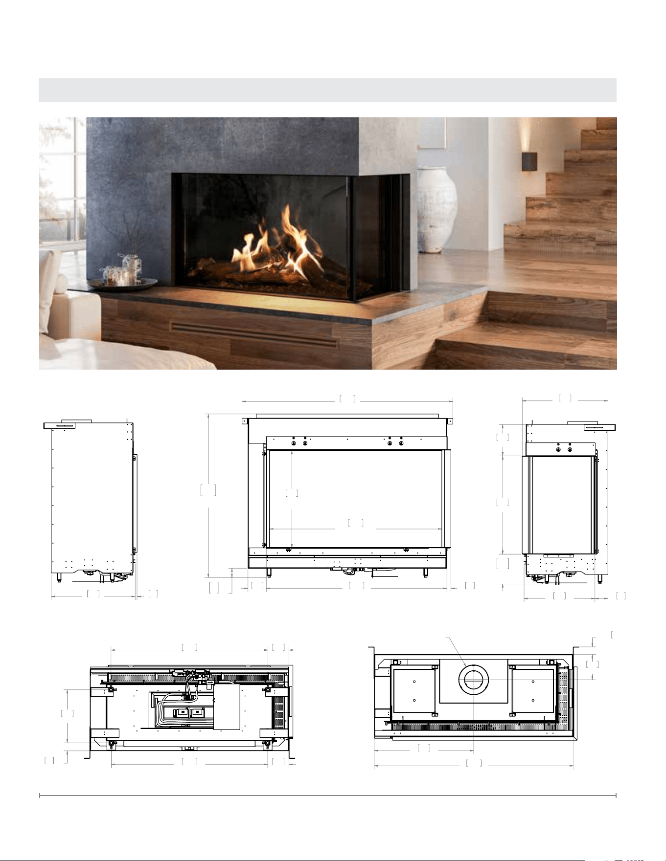
17
FaberFires.com
Fireplace Information
FMG4726R - Right-facing Built-in Gas Fireplace
Technical Dimensions
648
25 1/2"
VIEWING AREA
1146
45 1/8"
VIEWING AREA
1109
1089
43 11/16"
42 7/8"
82
62
3 3/16"
2 7/16"
122
4 13/16"
1202
47 5/16"
27
1 1/16"
1403
55 1/4"
558
22"
13
1/2"
209
8 1/4"
654
25 3/4"
472
18 9/16"
87
3 7/16"
571
22 1/2"
218
198
8 9/16"
7 3/4"
VENT 5" X 8"
169
6 5/8"
MIN.
51
2"
1326
52 3/16"
662
26 1/16"
139
5 1/2"
53
2 1/16"
1040
40 15/16"
141
5 9/16"
354
13 15/16"
1045
41 1/8"
ISOMETRIC VIEW
FOR REFERENCE ONLY
648
25 1/2"
VIEWING AREA
1146
45 1/8"
VIEWING AREA
1109
1089
43 11/16"
42 7/8"
82
62
3 3/16"
2 7/16"
122
4 13/16"
1202
47 5/16"
27
1 1/16"
1403
55 1/4"
558
22"
13
1/2"
209
8 1/4"
654
25 3/4"
472
18 9/16"
87
3 7/16"
571
22 1/2"
218
198
8 9/16"
7 3/4"
VENT 5" X 8"
169
6 5/8"
MIN.
51
2"
1326
52 3/16"
662
26 1/16"
139
5 1/2"
53
2 1/16"
1040
40 15/16"
141
5 9/16"
354
13 15/16"
1045
41 1/8"
ISOMETRIC VIEW
FOR REFERENCE ONLY
648
25 1/2"
VIEWING AREA
1146
45 1/8"
VIEWING AREA
1109
1089
43 11/16"
42 7/8"
82
62
3 3/16"
2 7/16"
122
4 13/16"
1202
47 5/16"
27
1 1/16"
1403
55 1/4"
558
22"
13
1/2"
209
8 1/4"
654
25 3/4"
472
18 9/16"
87
3 7/16"
571
22 1/2"
218
198
8 9/16"
7 3/4"
VENT 5" X 8"
169
6 5/8"
MIN.
51
2"
1326
52 3/16"
662
26 1/16"
139
5 1/2"
53
2 1/16"
1040
40 15/16"
141
5 9/16"
354
13 15/16"
1045
41 1/8"
ISOMETRIC VIEW
FOR REFERENCE ONLY
648
25 1/2"
VIEWING AREA
1146
45 1/8"
VIEWING AREA
1109
1089
43 11/16"
42 7/8"
82
62
3 3/16"
2 7/16"
122
4 13/16"
1202
47 5/16"
27
1 1/16"
1403
55 1/4"
558
22"
13
1/2"
209
8 1/4"
654
25 3/4"
472
18 9/16"
87
3 7/16"
571
22 1/2"
218
198
8 9/16"
7 3/4"
VENT 5" X 8"
169
6 5/8"
MIN.
51
2"
1326
52 3/16"
662
26 1/16"
139
5 1/2"
53
2 1/16"
1040
40 15/16"
141
5 9/16"
354
13 15/16"
1045
41 1/8"
ISOMETRIC VIEW
FOR REFERENCE ONLY
648
25 1/2"
VIEWING AREA
1146
45 1/8"
VIEWING AREA
1109
1089
43 11/16"
42 7/8"
82
62
3 3/16"
2 7/16"
122
4 13/16"
1202
47 5/16"
27
1 1/16"
1403
55 1/4"
558
22"
13
1/2"
209
8 1/4"
654
25 3/4"
472
18 9/16"
87
3 7/16"
571
22 1/2"
218
198
8 9/16"
7 3/4"
VENT 5" X 8"
169
6 5/8"
MIN.
51
2"
1326
52 3/16"
662
26 1/16"
139
5 1/2"
53
2 1/16"
1040
40 15/16"
141
5 9/16"
354
13 15/16"
1045
41 1/8"
ISOMETRIC VIEW
FOR REFERENCE ONLY
LEFT SIDE FRONT
TOP VIEW
BOTTOM VIEW (FEET LOCATION)
RIGHT SIDE
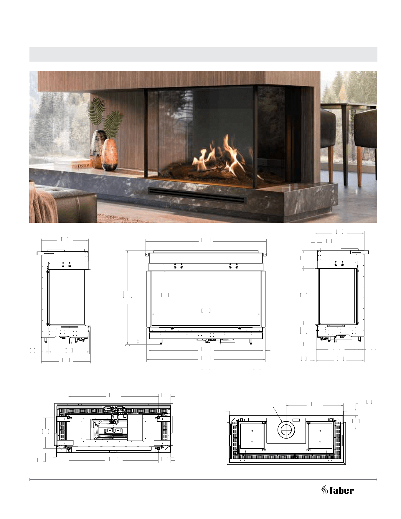
18
FMG5126B - Bay Built-in Gas Fireplace
Technical Dimensions
LEFT SIDE
FRONT
TOP VIEWBOTTOM VIEW (FEET LOCATION)
RIGHT SIDE
1256
49 7/16"
VIEWING AREA
1109
1089
43 11/16"
42 7/8"
82
62
3 3/16"
2 7/16"
1323
52 1/16"
663
26 1/16"
VIEWING AREA
1403
55 1/4"
27
1 1/16"
1377
54 3/16"
572
22 1/2"
472
18 9/16"
87
3 7/16"
547
21 9/16"
209
8 1/4"
654
25 3/4"
218
198
8 9/16"
7 3/4"
14
9/16"
558
22"
87
3 7/16"
472
18 9/16"
571
22 1/2"
24
15/16"
MIN.
51
2"
169
6 5/8"
662
26 1/16"
VENT 8" X 5"
1045
41 1/8"
139
5 1/2"
141
5 9/16"
1040
40 15/16"
354
13 15/16"
53
2 1/16"
ISOMETRIC VIEW
FOR REFERENCE ONLY
1256
49 7/16"
VIEWING AREA
1109
1089
43 11/16"
42 7/8"
82
62
3 3/16"
2 7/16"
1323
52 1/16"
663
26 1/16"
VIEWING AREA
1403
55 1/4"
27
1 1/16"
1377
54 3/16"
572
22 1/2"
472
18 9/16"
87
3 7/16"
547
21 9/16"
209
8 1/4"
654
25 3/4"
218
198
8 9/16"
7 3/4"
14
9/16"
558
22"
87
3 7/16"
472
18 9/16"
571
22 1/2"
24
15/16"
MIN.
51
2"
169
6 5/8"
662
26 1/16"
VENT 8" X 5"
1045
41 1/8"
139
5 1/2"
141
5 9/16"
1040
40 15/16"
354
13 15/16"
53
2 1/16"
ISOMETRIC VIEW
FOR REFERENCE ONLY
1256
49 7/16"
VIEWING AREA
1109
1089
43 11/16"
42 7/8"
82
62
3 3/16"
2 7/16"
1323
52 1/16"
663
26 1/16"
VIEWING AREA
1403
55 1/4"
27
1 1/16"
1377
54 3/16"
572
22 1/2"
472
18 9/16"
87
3 7/16"
547
21 9/16"
209
8 1/4"
654
25 3/4"
218
198
8 9/16"
7 3/4"
14
9/16"
558
22"
87
3 7/16"
472
18 9/16"
571
22 1/2"
24
15/16"
MIN.
51
2"
169
6 5/8"
662
26 1/16"
VENT 8" X 5"
1045
41 1/8"
139
5 1/2"
141
5 9/16"
1040
40 15/16"
354
13 15/16"
53
2 1/16"
ISOMETRIC VIEW
FOR REFERENCE ONLY
1256
49 7/16"
VIEWING AREA
1109
1089
43 11/16"
42 7/8"
82
62
3 3/16"
2 7/16"
1323
52 1/16"
663
26 1/16"
VIEWING AREA
1403
55 1/4"
27
1 1/16"
1377
54 3/16"
572
22 1/2"
472
18 9/16"
87
3 7/16"
547
21 9/16"
209
8 1/4"
654
25 3/4"
218
198
8 9/16"
7 3/4"
14
9/16"
558
22"
87
3 7/16"
472
18 9/16"
571
22 1/2"
24
15/16"
MIN.
51
2"
169
6 5/8"
662
26 1/16"
VENT 8" X 5"
1045
41 1/8"
139
5 1/2"
141
5 9/16"
1040
40 15/16"
354
13 15/16"
53
2 1/16"
ISOMETRIC VIEW
FOR REFERENCE ONLY
1256
49 7/16"
VIEWING AREA
1109
1089
43 11/16"
42 7/8"
82
62
3 3/16"
2 7/16"
1323
52 1/16"
663
26 1/16"
VIEWING AREA
1403
55 1/4"
27
1 1/16"
1377
54 3/16"
572
22 1/2"
472
18 9/16"
87
3 7/16"
547
21 9/16"
209
8 1/4"
654
25 3/4"
218
198
8 9/16"
7 3/4"
14
9/16"
558
22"
87
3 7/16"
472
18 9/16"
571
22 1/2"
24
15/16"
MIN.
51
2"
169
6 5/8"
662
26 1/16"
VENT 8" X 5"
1045
41 1/8"
139
5 1/2"
141
5 9/16"
1040
40 15/16"
354
13 15/16"
53
2 1/16"
ISOMETRIC VIEW
FOR REFERENCE ONLY
19
FaberFires.com
© 2019 Mertik Maxitrol GmbH & Co. KG, All Rights Reserved.
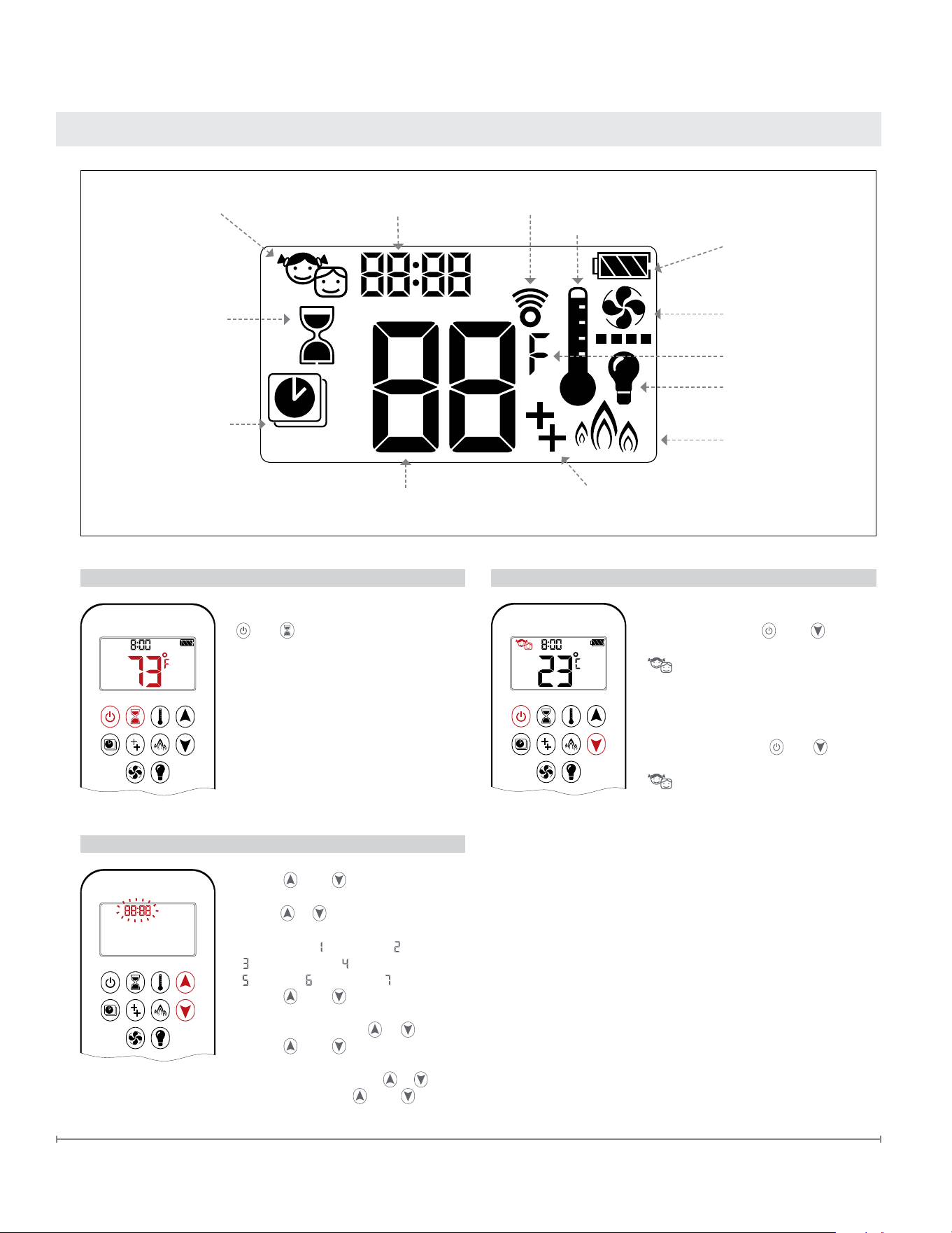
Remote Control Instructions
Gas Fireplace Operation
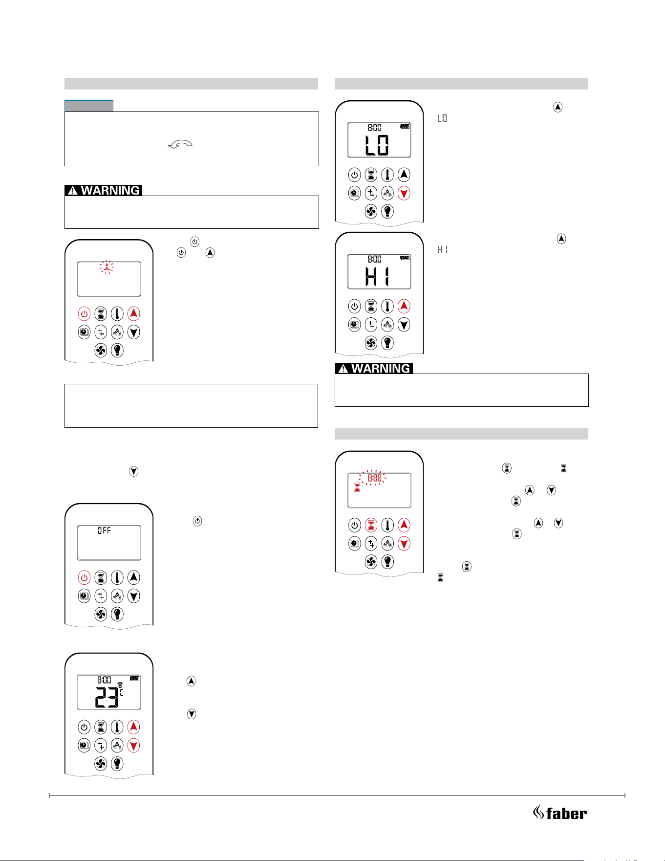
CHILD PROOF
ON:
▪ To activate press
and buttons
simultaneously.
▪
is displayed and the Symax is
rendered inoperable, except for the
OFF function.
OFF :
▪ To deactivate press
and buttons
simultaneously.
▪ disappears.
SETTING FAHRENHEIT OR CELSIUS
AM
▪
To change between °C and °F, press
and buttons simultaneously.
NOTE: Choosing °F results in a 12 hour
clock. Choosing °C results in a
24 hour clock.
SETTING THE TIME
1. Press and
2. Press
or button to select a num-
ber to correspond with the day of the
week (e. g.
= Monday, = Tuesday,
= Wed nesday, = Thursday,
=
Friday,
= Sat urday, = Sunday).
3. Press
and
4. To select hour press
or button.
5. Press
and buttons
simultaneously. Minutes ashes.
simultaneously. Day ashes.
simultaneously. Hours ashes.
6.
To select minutes press or button.
7. and buttons
simultaneously or wait.
To conrm press
Light
Fan
Program Mode
Temperature
Time
2
nd
Burner Feature
Countdown Timer
Battery Status
Signal Indicator Child Proof
Eco Mode
Thermostatic Mode
1 2
ON
AM
PM
OFF
Fahrenheit or Celsius
CHILD PROOF
ON:
▪ To activate press
and buttons
simultaneously.
▪
is displayed and the Symax is
rendered inoperable, except for the
OFF function.
OFF :
▪ To deactivate press
and buttons
simultaneously.
▪ disappears.
SETTING FAHRENHEIT OR CELSIUS
AM
▪
To change between °C and °F, press
and buttons simultaneously.
NOTE: Choosing °F results in a 12 hour
clock. Choosing °C results in a
24 hour clock.
SETTING THE TIME
1. Press and
2. Press
or button to select a num-
ber to correspond with the day of the
week (e. g. = Monday, = Tuesday,
= Wed nesday, = Thursday,
=
Friday,
= Sat urday, = Sunday).
3. Press
and
4. To select hour press
or button.
5. Press
and buttons
simultaneously. Minutes ashes.
simultaneously. Day ashes.
simultaneously. Hours ashes.
6.
To select minutes press or button.
7. and buttons
simultaneously or wait.
To conrm press
Light
Fan
Program Mode
Temperature
Time
2
nd
Burner Feature
Countdown Timer
Battery Status
Signal Indicator Child Proof
Eco Mode
Thermostatic Mode
1 2
ON
AM
PM
OFF
Fahrenheit or Celsius
20
© 2019 Mertik Maxitrol GmbH & Co. KG, All Rights Reserved.
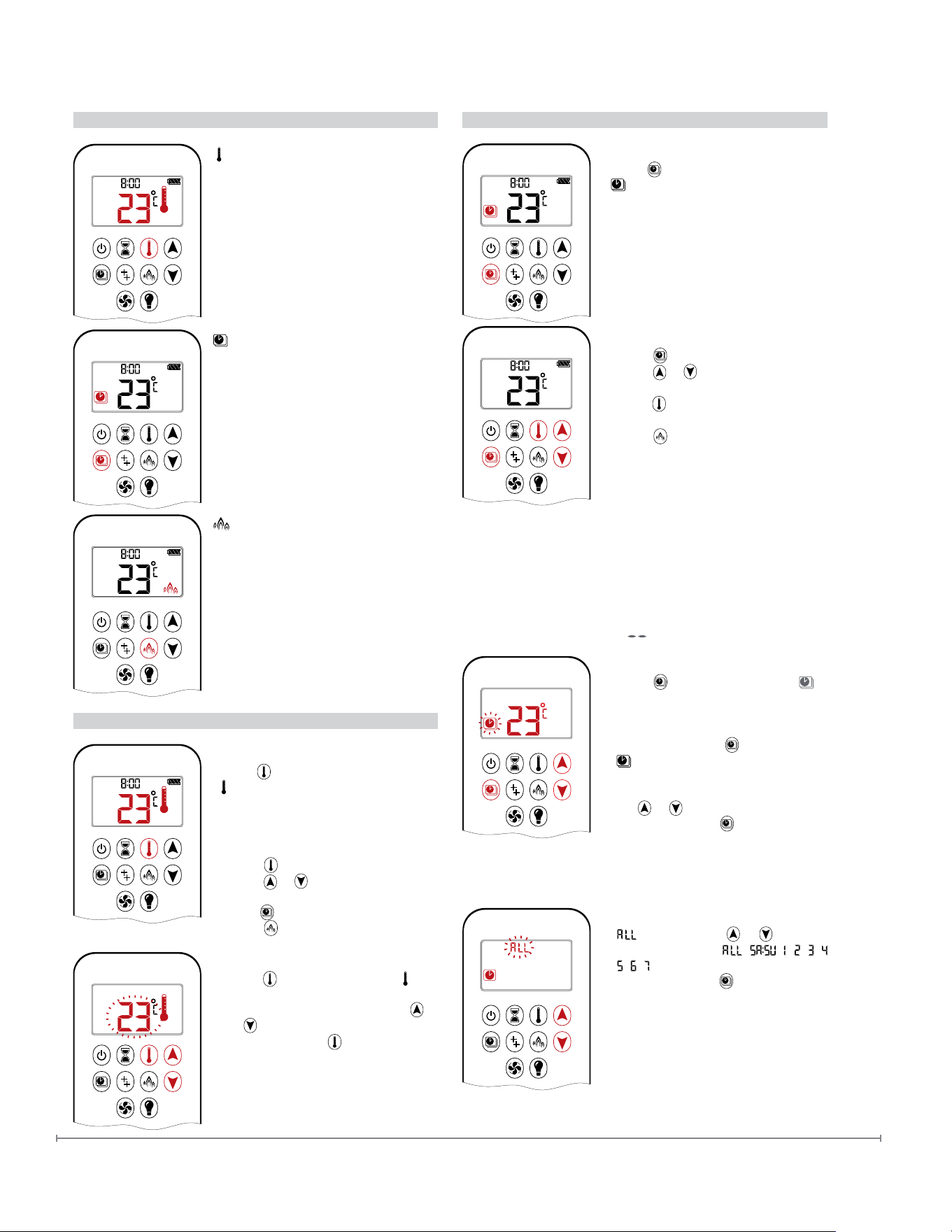
▪ Press button (One Button Ignition)
or and button simultaneously
(Two Button Ignition) until two short
beeps (CE version) or continuous
beeping (CSA version) and a blinking
series of lines conrms the start
sequence has begun; release
button(s).
▪ Main gas ows once pilot ignition is
conrmed.
▪ The Symax automatically goes into
Manual Mode after main burner
ignition.
MANUAL MODE (HANDSET)
NOTICE
BEFORE OPERATING
1. Make sure MANUAL knob on the GV60 valve is in the
When pilot ignition is conrmed, motor turns automatically
to maximum ame height.
ON,
full counterclockwise
position.
2.
Place the ON / OFF switch (if equipped) in the I (ON) position.
TO TURN ON FIRE
1 2
ON
OFF
If the pilot does not stay lit after several tries, turn the main
valve knob to OFF and follow the instructions “TURN OFF
GAS TO APPLIANCE” (see page 10).
STANDBY MODE (PILOT FLAME)
Handset
▪
Press and hold
button to set appliance to pilot ame.
TO TURN OFF FIRE
ON
AM
PM
OFF
Handset
▪ Press
button to turn o.
NOTE: A new ignition is possible after
the OFF icon stops ashing.
FLAME HEIGHT ADJUSTMENT
ON
AM
PM
OFF
Handset
▪
hold
To increase ame height press and
To decrease ame height or to set
appliance to pilot ame, press and
hold
button.
▪
button.
DESIGNATED LOW FIRE AND HIGH FIRE
AM
▪
▪
is displayed.
NOTE:
AM
▪ To go to high re, double-click
Flame goes to high re rst
before going to low re.
To go to low re, double-click
button.
button.
▪ is displayed.
If the appliance will not operate, follow the instructions
“TURN OFF GAS TO APPLIANCE”
(see page 10).
COUNTDOWN TIMER
F
ON / SETTING:
1. Press and hold button until is
displayed, and hour
ashes.
2. To select hour press
or button.
3.
button. Minutes
4. To select minutes press
To conrm press
To conrm press
ash.
or button.
5.
button or wait.
OFF :
▪ Press
button.
▪
and Countdown Time disappear.
NOTE:
At end of Countdown Time period, the re shuts o.
The Countdown Timer only works in Manual,
Thermostatic, and Eco Modes. Maximum Countdown
Time is 9 hours and 50 minutes.
21
FaberFires.com
Gas Fireplace Operation
© 2019 Mertik Maxitrol GmbH & Co. KG, All Rights Reserved.
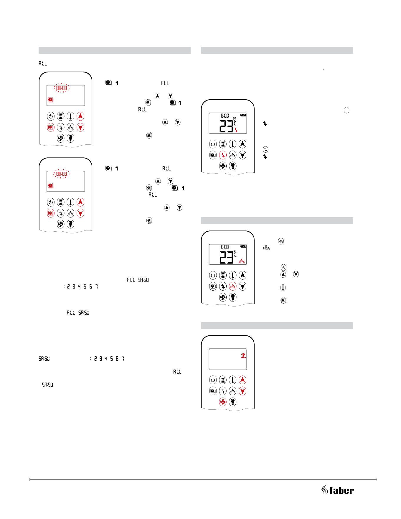
MODES OF OPERATION
Thermostatic Mode
The room temperature is measured and
compared to the set temperature. The
adjusted to achieve the set temperature.
ame height is then automatically
1 2
ON
AM
PM
OFF
Program Mode
PROGRAM 1 and 2, each can be
programmed to go ON and OFF
at specic times at a set temperature.
AM
Eco Mode
Flame height modulates between high
and low. If the room temperature is
lower than the set temperature, the
ameheight stays onhigh for a longer
period of time. If the room temperature
higher than the set temperature, the
ame height stays on low for a longer
period of time. One cycle lasts approx.
20 minutes.
THERMOSTATIC MODE
ON:
▪ Press
button.
▪
is displayed, preset temperature is
temperature is displayed.
displayed briey, and then room
OFF :
1. Press
button.
2. Press
or button to enter Manual
Mode.
3. Press button
to enter Program Mode.
4. Press button to enter Eco Mode.
SETTING:
1. Press
displayed, temperature ashes.
button and hold until is
2. To adjust set temperature press
To conrm press
or
button.
3.
button or wait.
PROGRAM MODE
1 2
ON
AM
PM
OFF
ON:
▪ Press
button.
▪
, or
, or is displayed.
OFF :
1. Press
button.
2. Press
or button to enter Manual
Mode.
3. Press button
to enter Thermostatic
Mode.
4. Press button to enter Eco Mode.
NOTE:
The set temperature for Thermostatic Mode is the
temperature for the ON time in Program Mode. Changing
the Thermostatic Mode set temperature also changes
the ON time temperature in Program Mode.
Default settings:
ON TIME (Thermostatic) TEMPERATURE: 70 °F / 21 °C
OFF TIME TEMPERATURE: “ “ (pilot ame only)
ON
TEMPERATURE SETTING:
1. Press
ashes
ON
and set temperature
button and hold until
(setting in Thermostatic Mode) is
displayed.
ashes.
2. To continue press
To conrm press
To conrm press
ashes. Press
button or wait.
,
OFF
is displayed, temperature
3. Select
OFF
temperature by pressing
the
or button.
4.
button.
NOTE: The ON (Thermostatic) and OFF set temperatures are
the same for each day.
DAY SETTING:
5.
or button to
choose between
, , , , , ,
, , .
6.
button.
OFF
2 ON1
22
© 2019 Mertik Maxitrol GmbH & Co. KG, All Rights Reserved.
selected
1
ON
AM
PM
OFF
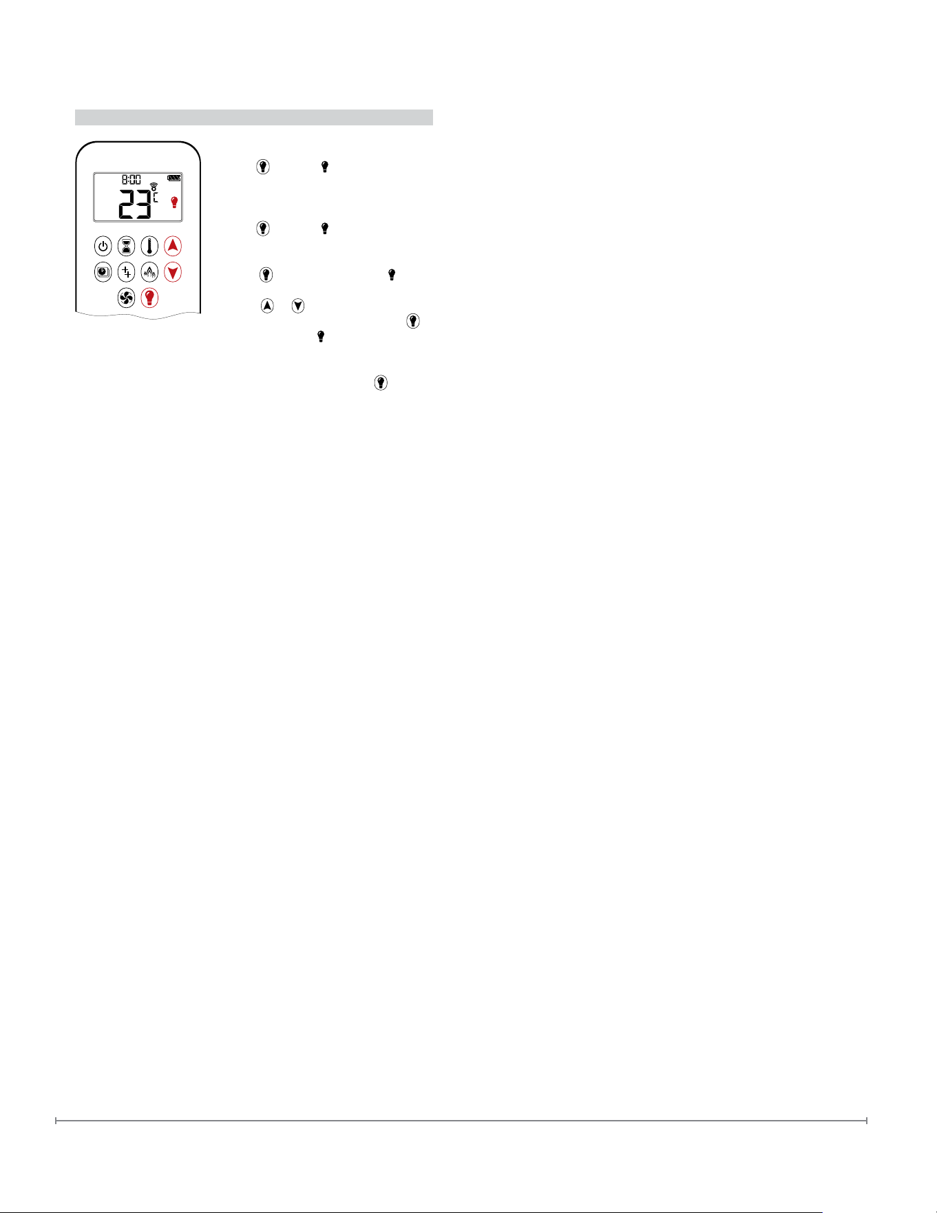
ON TIME SETTING (PROGRAM 1):
7.
, , ON is displayed, is
displayed shortly, and hour ashes.
8. To select hour press
To conrm press
To conrm press
To conrm press
To conrm press
or button.
9.
button. , , ON
is displayed,
displayed shortly,
and minutes ash.
10. To select minutes press
or
button.
11.
button.
OFF TIME SETTING (PROGRAM 1):
1
ON
AM
PM
OFF
12. , ,
OFF is displayed, is
displayed shortly, and hour ashes.
13. To select hour, press
or button.
14.
button. , ,
OFF is displayed,
is displayed
shortly, and minutes ash.
15. To select minutes press
or
button.
16.
button.
NOTE: Either continue to PROGRAM 2 and set ON and OFF
times or stop programming at this point, and
PROGRAM 2 remains deactivated.
NOTE: PROGRAM 1 and 2 use the same ON (Thermostatic)
and OFF temperatures for
, and Daily Timer
,
, , , , , ). Once a new ON (Thermostatic)
and/or OFF temperature has been set, that
temperature becomes the new default setting.
NOTE: If
, or Daily Timer are programmed for
PROGRAM 1 and PROGRAM 2 ON and OFF times,
thesebecome the new default times. The batteries
must be removed to clear the PROGRAM 1 and
PROGRAM 2 ON and OFF times and temperatures.
or Daily Timer ( , , , , , , ) selected
▪ Set ON time and OFF time using same procedure as
“selected” (above).
▪
:
Set ON time and OFF time for both Saturday and Sunday.
▪ Daily Timer: Unique
Wait to nish setting.
ON and OFF times may be set for a single
day of the week, for multiple days of the week, or for every day
of the week.
2
ND
BURNER FEATURE
The latching solenoid valve will open automatically after ignition
or after switching the system OFF, so that the maximum ow of
gas is supplied to both burners assisting with the ignition process.
After pressing the button for the 2
nd
Burner the motor will turn
7 seconds in the ON direction until the max. position is reached.
ON
AM
PM
OFF
ON:
▪
To switch a burner ON, press the
button.
▪
displayed.
OFF :
▪ To switch the burner OFF, press the
button.
▪
disappears.
NOTE: The latching solenoid valve cannot operate manually. If
the Receiver battery runs down it will remain in the last
operating position.
ECO MODE
AM
ON:
▪ Press
button to enter Eco Mode.
▪
is displayed.
OFF :
1. Press
button.
2. Press
or button to enter Manual
Mode.
3. Press button to enter Thermostatic
Mode.
4. Press
button to enter Program
Mode.
CIRCULATING FAN OPERATION
AM
Does not apply to the models
referenced in this manual.
PROGRAM MODE
(
23
FaberFires.com
Gas Fireplace Operation
© 2019 Mertik Maxitrol GmbH & Co. KG, All Rights Reserved.
AM
ON:
▪ Press
button ( is displayed).
▪ Light is ON at preset level.
OFF :
▪ Press
button ( disappears).
SETTING:
1.
Press ashes. button and hold until
2. To adjust light between 20…100%
press
or button.
3.
button or wait (
To conrm setting either press
is displayed).
NOTE:
you want the light ON but no ame, press
The Light works independently of the pilot ame. If
button.
LIGHT/DIMMER OPERATION
24
Receiver and Remote Batteries
Pairing Remote with Fireplace Receiver
Remote Control Batteries
• 2 × AAA (alkaline recommended).
• Low battery indicator on handsets with display.
• Battery replacement is recommended every
2 years.
Receiver Batteries
• 4 × AA (alkaline ONLY)
• Low battery indicator: Frequent beeps for 3 seconds
when motor turns.
• If A/C adaptor is not used, battery replacement is
recommended at the beginning of each heating
season as part of the yearly service check.
Your remote will come paired with the replace
receiver and will be ready for operation out of the box.
In the event of remote or receiver replacement, use
the following procedure to pair the remote with the
receiver:
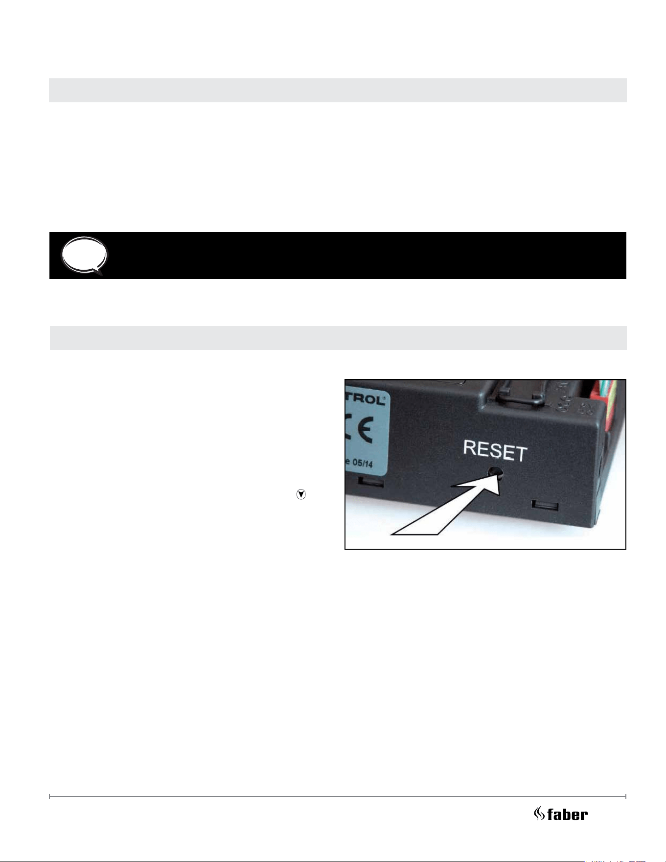
1. Press and hold the receiver’s reset button (see
Figure 1) until you hear two (2) beeps. The rst
beep is short, and the second beep is long. After
the second beep, release the reset button.
2. Within the subsequent 20 seconds, press the
20 / 30
INSTALLATION AND OPERATING INSTRUCTIONS FOR OEM USE ONLY
© 2019 Mertik Maxitrol GmbH & Co. KG, All Rights Reserved.
selected
1 2
ON
AM
PM
OFF
ON TIME SETTING (PROGRAM 1):
7.
, , is displayed, is dis-
played shortly, and hour ashes.
8. To select hour press
or button.
9. To conrm press
button. , ,
is displayed, displayed shortly,
and minutes ash.
10. To select minutes press
or but-
ton.
11. To conrm press
button.
OFF TIME SETTING (PROGRAM 1):
1 2
ON
AM
PM
OFF
12. , ,
is displayed, is dis-
played shortly, and hour ashes.
13. To select hour, press
or button.
14. To conrm press
button. , ,
is displayed, is displayed
shortly, and minutes ash.
15. To select minutes press
or but-
ton.
16. To conrm press
button.
NOTE: Either continue to PROGRAM 2 and set ON and OFF
times or stop programming at this point, and PRO-
GRAM 2 remains deactivated.
NOTE: PROGRAM 1 and 2 use the same ON (Thermostatic)
and OFF temperatures for
,
and Daily Timer ( ,
, , , , , ). Once a new ON (Thermostatic) and / or
OFF temperature has been set, that temperature be-
comes the new default setting.
NOTE: If
,
or Daily Timer are programmed for PRO-
GRAM 1 and PROGRAM 2 ON and OFF times, these
become the new default times. The batteries must be
removed to clear the PROGRAM 1 and PROGRAM 2
ON and OFF times and temperatures.
or Daily Timer ( , , , , , , ) selected
▪ Set ON time and OFF time using same procedure as “ se-
lected” (above).
▪
:
Set ON time and OFF time for both Saturday and Sunday.
▪ Daily Timer: Unique ON and OFF times may be set for a single
day of the week, for multiple days of the week, or for every day
of the week.
▪ Wait to nish setting.
2
ND
BURNER FEATURE
The latching solenoid valve will open automatically after ignition
or after switching the system OFF, so that the maximum ow of
gas is supplied to both burners assisting with the ignition process.
After pressing the button for the 2
nd
Burner the motor will turn 7
seconds in the ON direction until the max. position is reached.
1 2
ON
AM
PM
OFF
ON:
▪
To switch a burner ON, press the
button.
▪
displayed.
OFF:
▪ To switch the burner OFF, press the
button.
▪
disappears.
NOTE: The latching solenoid valve cannot operate manually. If
the Receiver battery runs down it will remain in the last
operating position.
ECO MODE
AM
ON:
▪ Press
button to enter Eco Mode.
▪
is displayed.
OFF:
1. Press
button.
2. Press
or button to enter Manual
Mode.
3. Press button
to enter Thermostatic
Mode.
4. Press
button to enter Program
Mode.
CIRCULATING FAN OPERATION
AM
Circulating fan has 4 speed levels from
low (1 bar) to high (4 bars).
ON / SETTING:
1. Press
button and hold until
ashes.
2. Press
button to increase fan speed
and
button to decrease fan speed.
3. To conrm setting either press
but-
ton or wait (
displayed).
OFF:
▪ Press
button until all 4 speed level
bars disappear.
NOTE: SETTING only. If the fan was not switched OFF after
last use, it starts automatically 4 minutes after ignition
at maximum speed and goes to the last set level after
10 seconds. The fan stops 10 minutes after the gas is
OFF or at pilot.
button on the handset until you hear two additional
short beeps conrming the code is set. If you hear
one long beep, this indicates the code learning
sequence has failed or the wiring is incorrect.
Figure 1
CAUTION: DO NOT USE a screwdriver or other metallic object to remove the batteries from
the battery box! This could cause a short circuit to the system.
25
FaberFires.com
1. Prior to starting the installation, make sure you read and understand all WARNING information in this manual.
Do not start the installation if you are unclear about any of the installation-related subjects.
2. Determine the following:
• The vent system conguration to be used based on the replace location.
• Clearance requirements from combustible and non-combustible materials.
• Gas supply piping.
• Electrical wiring requirements.
• Framing and nishing details.
3. Unpack the replace box, following instructions for replace unpacking.
4. Put the replace in the desired location. Verify clearance to non-combustible and combustible materials. Follow
the clearance instructions in this manual.
5. Attach the brackets of the unit to the wall framing
6. Connect the vent system to the replace.
7. Connect the gas line to the replace and verify gas inlet and outlet pressure.
8. Conrm if adjustments for high altitude are needed (installation at above 4500 ft from sea level).
9. Install receiver batteries or if using mains power, ensure electrical outlet is within 2.5m and plug AC/DC adaptor
to receiver and to wall receptacle.
10. Insert and place Fireplace media. Use media arrangement guide from the manual.
11. Verication of: • Ignition and pilot system.
• Burning and ame.
• Remote control Setup
12. Complete framing and wall cover.
13. Remove blue protective lm from glass and clean glass.
14. Re-install the glass, and unpack and install the safety barrier.
15. Ensure the homeowner is familiar with operation of the replace and remote control, and can locate the the
ignition instructions and rating label.
16. Ensure the homeowner has paperwork showing the details of the replace (model, serial number, installation
date) and the details of the installer.
17. Ensure the homeowner is aware of regular maintenance schedules and potential problems that will require
service.
WARNING! Risk of re or explosion! Damaged parts could impair safe operation.
DO NOT install damaged, incomplete or substitute components.
Installation Steps
!
WARNING
Read all the instructions before starting the installation. Follow these instructions carefully
during the installation to ensure maximum safety and benet. Follow the steps above to
ensure proper installation of the gas appliance.
26
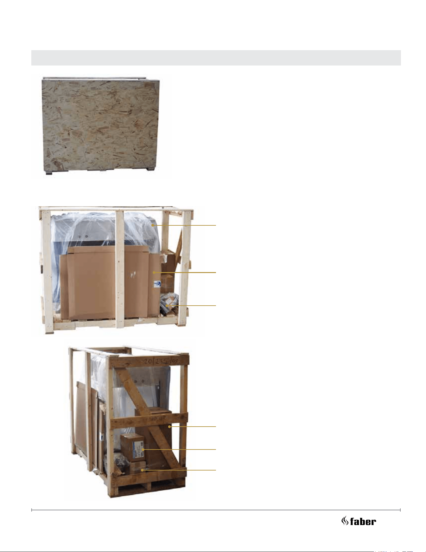
Fireplace Unpacking and Contents
Installation Preparation
MatriX Firebox
Safety Screen
Remote, Manual, Accessories
Logs
DuraVent Adaptor
Decorative Glass
The Faber MatriX replace is supplied with the following contents. Ensure all components are present
before installation. All components may not be packed exactly as shown.
Remove the outer protective crate from the pallet.
27
FaberFires.com
Fireplace Positioning
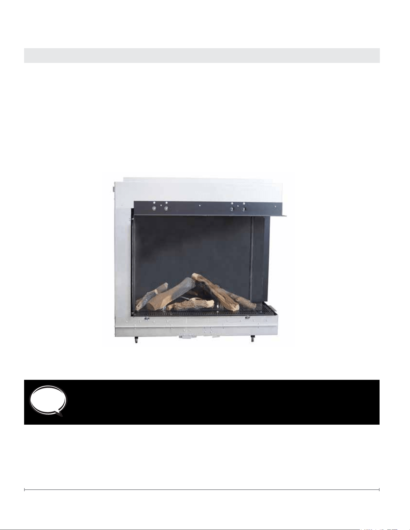
Once the replace has been set to the upright position, it can be moved to its nal installation location.
• Make sure the control unit is secure and not dragging on the oor during transport and positioning.
• Unit should remain on the pallet during transport inside the site location.
• When positioning the replace, take into consideration the clearance requirements and framing.
• Ensure unit is level. Adjust feet to level unit if necessary.
• Attach the replace top brackets to the metal stud in the back to secure the replace. The bracket
length can be adjusted by releasing the screws on the top.
Fireplace should remain on the wood pallet when carried to nal installation location.
Do not attempt to use a pallet jack or any other moving tools if the unit has been
removed from the wood pallet as it may harm the replace components under the unit.
Installation Preparation
28
1. Where a vent pipe passes through a oor or ceiling, a ceiling restop MUST be used to retain insulation and
maintain proper clearances. Use roof support brackets where needed.
2. Install the rst section of vent pipe into the collar on top of the replace.
3. Connections between each vent system component must be tightly joined and secured. Follow the vent
manufacturer’s instructions for information on how to seal and secure vent and vent connections.
4. Horizontal runs of vent pipe must be supported to prevent any downward sags. Horizontal pipe sections should
be supported at least every 4 feet. Wall straps can be used for this purpose.
5. When installing the vent pipe, make sure that the vent pipe is supported by the structural/frame surrounding
and not by replace.
Follow the vent manufacturer’s instruction for information on how to install, seal, and secure vent and vent
connections.
Framing for vents in combustible walls and ceilings:
When passing through combustible walls and ceilings, framing will depend on the type of vent installation −
horizontal or vertical. Ensure that the insulation is kept clear of the vent pipe using either a wall thimble or an attic
insulation shield. Follow the installation instructions supplied with the individual venting components.
Approved Pipe - This appliance is approved for use with M&G DuraVent venting.
DO NOT mix pipe, ttings or joining methods from dierent manufacturers.
For detailed chimney installation information please use the manufacturer's direct vent installation manual.
DO NOT pack insulation around the vent. Insulation must be kept back from the pipe to prevent overheating.
ALWAYS maintain specied clearances around venting and restop systems. Install wall shield and ceiling
restops as specied.
Vent Size
Models Vent Size
FMG3326F
FMG3726L
FMG3726R
FMG4126B
FMG4326F
FMG4726L
FMG4726R
FMG5126B
5x8
The replace will require a 5" × 8" vent.
Instructions
Vent Termination
These instructions should be used as a guideline and do not supersede local codes
in any way. Install venting according to local codes, these instructions, the current
National Fuel Gas Code (ANSl-2223.1) and/or Natural Gas and Propane Installation
Code, CSA B149.1
!
WARNING
29
FaberFires.com
Vent Termination
Minimum Combustible Clearances from Vent
• Horizontal Vent Clearances
A minimum clearance of 3" (76 mm) to the top and 1" (26 mm) to the
sides and bottom of the vent pipe on all horizontal runs to combustibles is
required.
• Vertical Vent Clearances
A minimum of 1" (26 mm) all around the vent pipe on all vertical runs to
combustibles is required except for clearances in appliance enclosures.
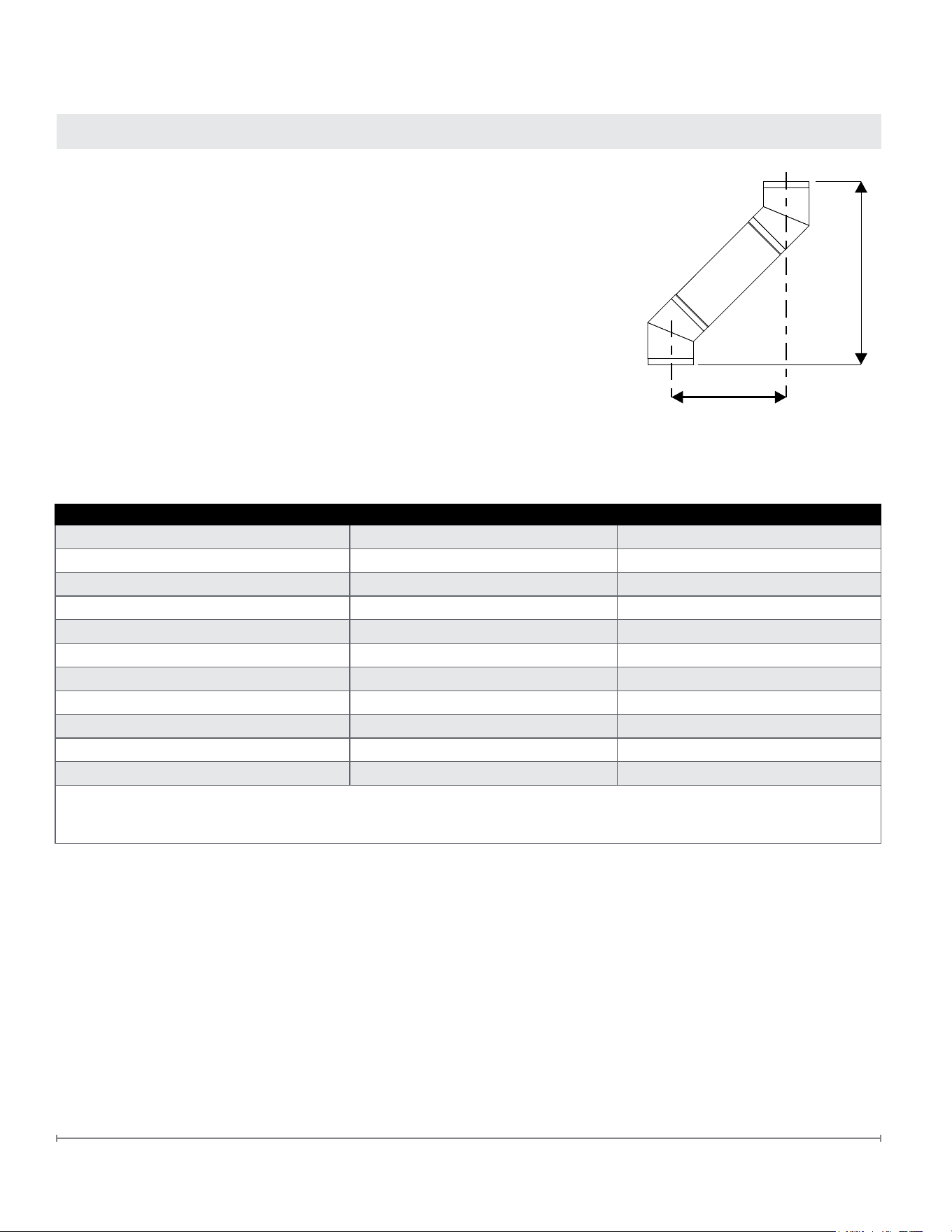
• Horizontal vents must have a minimum ¼" (6 mm) rise per 1 foot towards
the termination.
Oset
Rise
DirectVent Pro and iCC Compatible Vent Terminations
Component Description DuraVent Stock Number ICC Stock Number
Wall Thimble 58DVA-WT TM-5WT
Wall Thimble (Small) 58DVA-WTS N/A
Wall Thimble (Universal) 58DVA-WTU N/A
Ceiling Support 58DVA-CS TM-5RDS
Fire Stop 58DVA-FS TM-5LS
Wall Fire Stop 58DVA-WFS TM-5TP
Vinyl Siding Stando 58DVA-VSS TM-VSS
Vinyl Siding Stando (4 Pc. Kit) 58DVA-VSK TM-VSS
Counter Flashing (Assembled) 58DVA-CF N/A
Appliance Adaptor N/A - Provided with appliance TM-5AA8
For specic instructions on venting components visit the manufacturers website listed below.
DuraVent Direct Vent Pro - www.duravent.com
Industrial Chimney Company (ICC) - www.icc-rsf.com
30
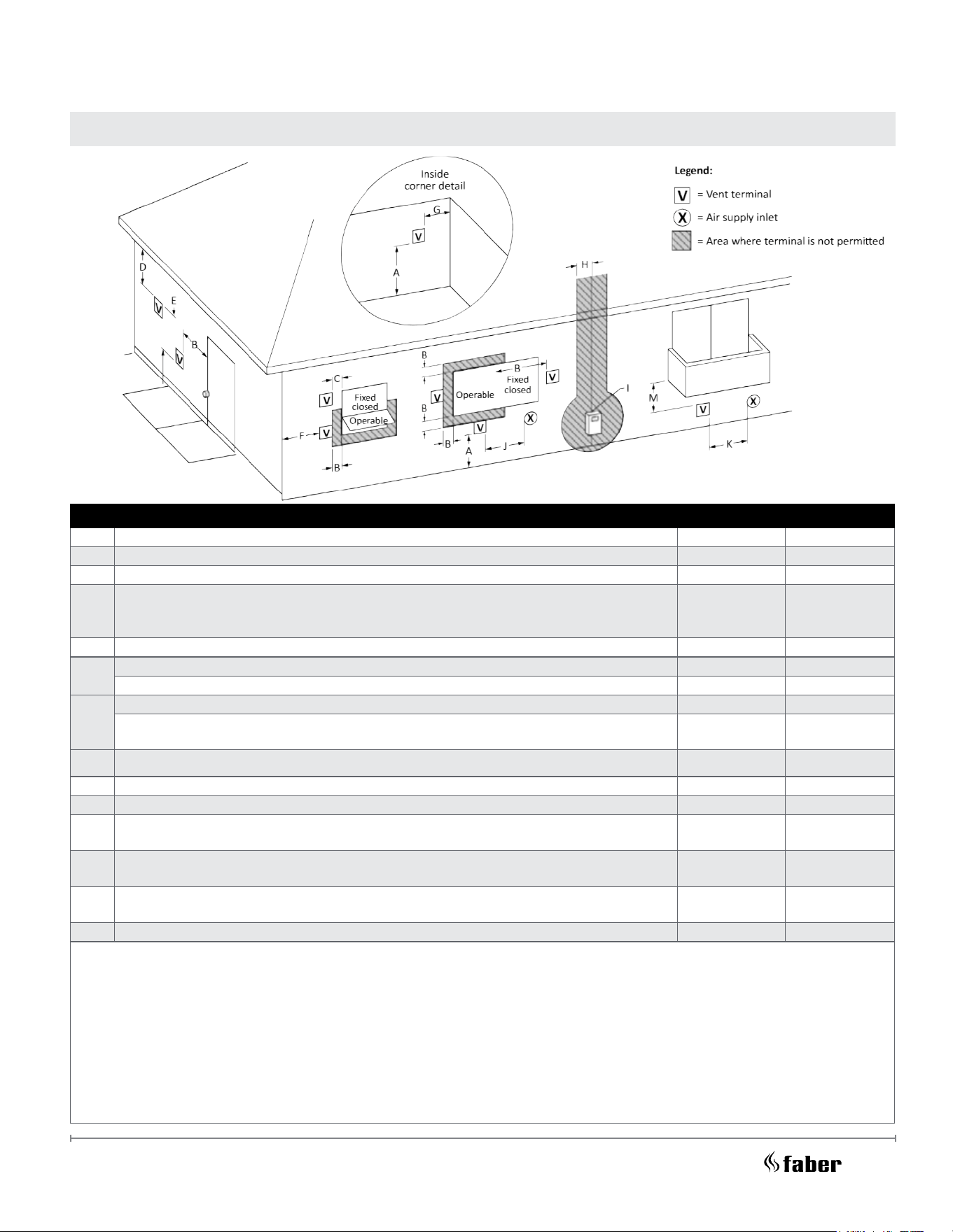
Minimum Clearance Requirements Canada¹ USA²
A Clearance above grade, veranda, porch, deck, or balcony 12" (30 cm) 12" (30 cm)
B Clearance to window or door that may be opened 12" (30 cm) 9" (23 cm)
C Clearance to permanently closed window See note³ See note³
D
Vertical clearance to ventilated sot located above the terminal within a
horizontal distance of 2 feet (61 cm) from the center line of the terminal
(check with the local code)
29" (74 cm) 29" (74 cm)
E Clearance to unventilated sot 20" (51 cm) 20" (51 cm)
F
Clearance to outside corner: with AstroCap Termination Cap. 7" (18 cm) 7" (18 cm)
Clearance to outside corner: with all other approved Termination Caps. 14" (36 cm) 14" (36 cm)
G
Clearance to inside comer: with AstroCap Termination Cap 7" (18 cm) 7" (18 cm)
Clearance to inside corner: with all other approved Termination Caps
12" (30 cm)
13" (33 cm)
12" (30 cm)
H
Clearance to each side of center line extended above meter/regulator assembly
36" (90 cm)⁶ See note³
I Clearances around meter/regulator 36" (90 cm) See note³
J Clearance to service regulator vent outlet 36" (90 cm) See note³
K
Clearance to non-mechanical air supply inlet to building or the combustion air
inlet to any other appliance
12" (30 cm) 9" (23 cm)
L
Clearance to a mechanical air supply inlet
#3’ (91cm) above if within 1 0’ (3m) horizontally.
72" (1.8 m) 36" (90 cm)⁷
M
Clearance above paved sidewalk or a paved driveway located on
public property
84" (2.1m)⁵ See note³
N Clearance under veranda, porch, deck, or balcony 12" (30 cm) See note³
Notes:
¹ In accordance with current CSA B149.1, Natural Gas and Propane Installation Code
² In accordance with the current ANSI Z223. 1/NFPA 54, National Fuel Gas Code
³ Clearance in accordance with local installation codes and the requirements of the gas supplier
⁴ A vent shall not terminate directly above a sidewalk or paved driveway which is located between two single
family dwellings and serves both dwellings
⁵ Permitted only if veranda, porch, deck, or balcony is fully open on a minimum of two sides beneath the oor
⁶ 3 feet (91 cm) within a height of 15 feet (4.5 m) above the meter/regulator assembly
⁷ 3 feet (91 cm) above - if within 10 feet (3 m) horizontally
Minimum Clearances to Vent Termination
31
FaberFires.com
Vent Termination
Unit Installation with Horizontal Termination
5" x 8" venting (Rigid Vent Systems)
Minimum Vent Clearances to Combustibles
Horizontal Top* 3" (76 mm)*
Horizontal Side 2" (51 mm)
Horizontal Bottom 2" (51 mm)
Vertical Vent 2" (51 mm)
* Clearances noted must be maintained except when
passing through a wall, ceiling or at the termination
where the use of a re stop or wall thimble reduces
clearance to 1-½" (38 mm).
These are the recommended framing dimensions
(inside measurements) for the 5" x 8" (127 x 203 mm)
rigid vent terminations - for use with a re stop or wall
thimble.
Recommended Framed Opening Size
Vent Size Framing Size
5" × 8" (127 x 203 mm) 11"×11" (279 x 279 mm)
lnstall the vent system according to the manufacturer’s instructions included with the components.
1. Set the unit in its desired location. Check to determine if wall studs or roof rafters are in the way when the
venting system is attached. If this is the case, you may want to adjust the location of the unit. Rough in the
gas preferably on the right side of the unit and the electrical (junction block is on the left side) on the left.
2. Direct vent pipe and ttings are designed with special twist-lock connections to connect the venting system to
the appliance ue outlet. A twist-lock appliance adaptor is required.
3. In conjunction with the Approved Ventsystem, install the adaptor after the unit is set in its desired location.
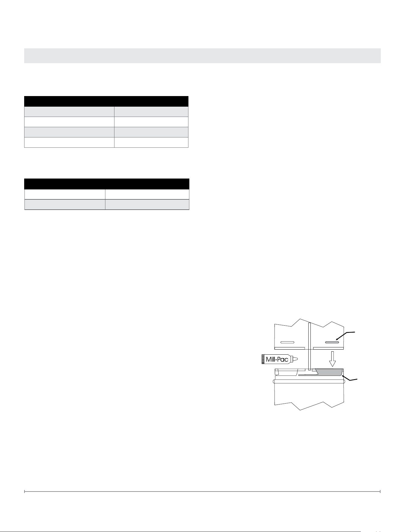
Put a bead of Mill-Pac inside the outer section of the adaptor and a bead of Mill-Pac on the inner collar. Slip
the adaptor over the existing inner and outer ue collar. Fasten to the
outer collar only with the 3 supplied screws (drilling pilot holes will make
this easier). This adaptor is typically factory installed.
4. Level the replace and fasten it to the framing using nails or screws
through the top and side nailing strips.
5. Assemble the desired combination of pipes and elbows to the appliance
adaptor and twist-lock for a solid connection.
!
NOTE: For best results and optimum performance with each
approved venting system , it is highly recommended to apply Mill-Pac
sealant (supplied) to every inner pipe connection. Failure to do so may
result in drafting or performance issues not covered under warranty.
!
NOTE: Horizontal runs of vent must be supported every 3 ft (0.9m).
Wall straps are available for this purpose.
6. Mark the wall for a square hole (see chart to left for size.) The center of the square hole should line up with
the centerline of the horizontal pipe. Cut and frame the square hole in the exterior wall where the vent will be
terminated. See diagram 2 for center line requirements.
If the wall being penetrated is constructed of non-combustible material, i.e., masonry block or concrete, an 8"
(203mm) diameter hole is acceptable.
Female
Locking
Lugs
Male
Locking
Lugs
C
L
C
L
Diagram 1
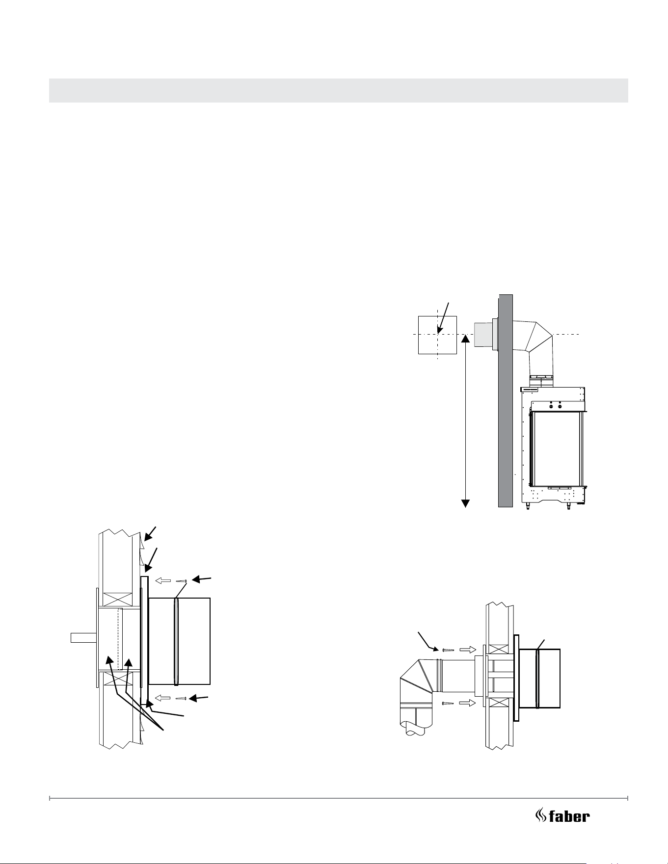
32
C
L
C
L
Unit Installation with Horizontal Termination
!
NOTE: a) The horizontal run of vent must be level, or have a ¼" rise for every 1 foot of run towards the
termination. Never allow the vent to run downward. This could cause high temperatures and may
present the possibility of a re.
b) The location of the horizontal vent termination on an exterior wall must meet all local and national
building codes.
7. Ensure that the pipe clearances to combustible materials are maintained (Diagram 3). Install the termination cap.
!
NOTE: If installing termination on a vinyl siding covered wall, a vinyl siding stando or furring strips must be used
to ensure that the termination is not recessed into the siding. The four wood screws provided should be replaced
with appropriate fasteners for stucco, brick, concrete, or other types of sidings.
C
L
C
L
Diagram 2
Minimum Height 72" (1829 mm)
Center of Hole
Wood Screws
C
L
C
L
Diagram 3
Wall Thimble
(Required)
Vinyl Siding Stando
Screws
Siding
Apply sealant to
all four sides
Bolt horizontal top to
vinyl stando
Diagram 4
8. Before connecting the horizontal run of vent pipe to the vent
termination, slide the Wall Thimble over the vent pipe. The wall
thimble is required for all horizontal terminations.
9. Slide the appliance and vent assembly towards the wall,
carefully inserting the vent pipe into the vent cap assembly.
It is important that the vent pipe extends into the vent cap at a
sucient distance so as to result in a minimum pipe overlap of
1-¼" (32 mm). Secure the connection between the vent pipe
and the vent cap.
10. Install wall thimble in the center of the framed hole and attach
with wood screws (Diagram 4).
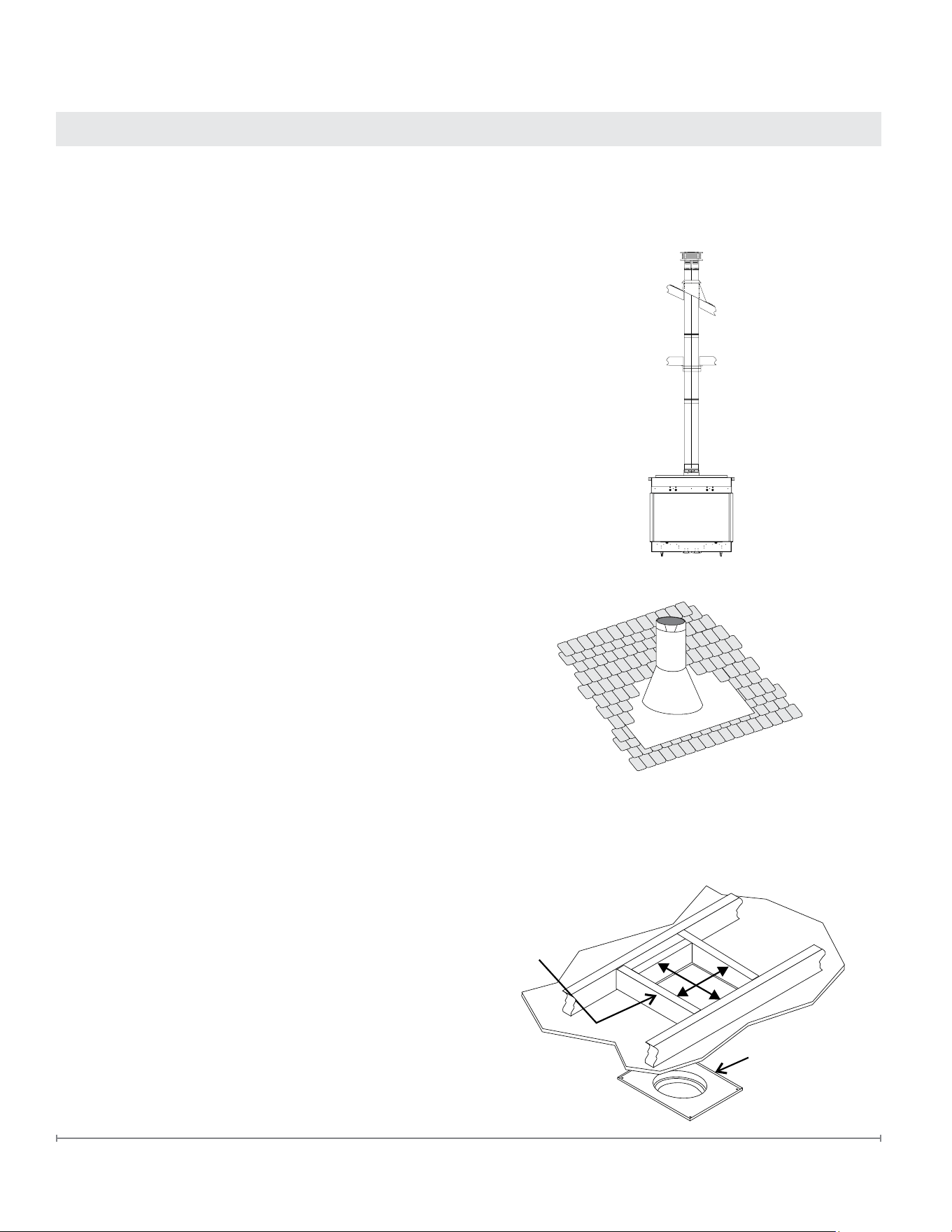
33
FaberFires.com
Vent Termination
Unit Installation with Vertical Termination
!
NOTE: A top clearance of 3"(76mm) and side bottom clearance of 2" (51 mm) must be maintained, except
when passing through a wall, ceiling, or at the termination where the use of a re stop or wall thimble reduces
the required clearance to 1-½" (38 mm). We recommend building a frame around the re stop or wall thimble to
give structural rigidity for mounting the termination. See manufacturer's table cutout dimensions for appropriate
sizing for component used.
1. Maintain the 1-½"(38 mm) clearances to
combustibles when passing through ceilings, walls,
roofs, enclosures, attic rafter, or other nearby
combustible surfaces, ensuring that the use of a re
stop or wall thimble is used as noted above. Do not
pack clearance space with insulation. Consult the
relevant section for the maximum vertical rise of the
venting system and the maximum horizontal oset
limitations.
2. Set the gas appliance in its desired location. Drop a
plumb bob down from the ceiling to the position of
the appliance ue exit, and mark the location where
the vent will penetrate the ceiling. Drill a small hole
at his point. Next, drop a plumb bob from the roof
to the hole previously drilled in the ceiling, and mark
the spot Diagram 2 where the vent will penetrate the
roof. Determine if ceiling joists, roof rafters or other
framing will obstruct the venting system. You may wish
to relocate the appliance or to oset to avoid cutting
load-bearing members.
3. A restop spacer must be installed in the oor or
ceiling of every level.
4. Assemble the desired lengths of pipe and elbows.
Ensure that all pipes and elbow connections are in the
fully twist-locked position and sealed.
!
NOTE: For best results and optimum performance
with each approved venting system, it is highly
recommended to apply ‟Mill-Pac” sealant to every inner
pipe connection. Failure to do so may result in drafting
or performance issues not covered under warranty.
5. Cut a hole in the roof centered on the small drilled
hole placed in the roof in Step 2. The hole should be of
sucient size to meet the minimum requirements for
clearance to combustibles of 1-½" (38 mm). Slip the
ashing under the shingles (shingles should overlap
half the ashing) as per Diagram 2.
6. Continue to assemble pipe lengths.
!
NOTE: If an oset is necessary in the attic to avoid
obstructions, it is important to support the vent pipe
every 3feet (0.9 meters), to avoid excessive stress on
the elbows, and possible separation. Wall straps are
available for this purpose.
The upper half of the ashing is installed
under the roong material and not nailed
down until the chimney is installed. This
allows for small adjustments.
Diagram 1
Diagram 2
Framing
Fire Stop
Spacer
Diagram 3
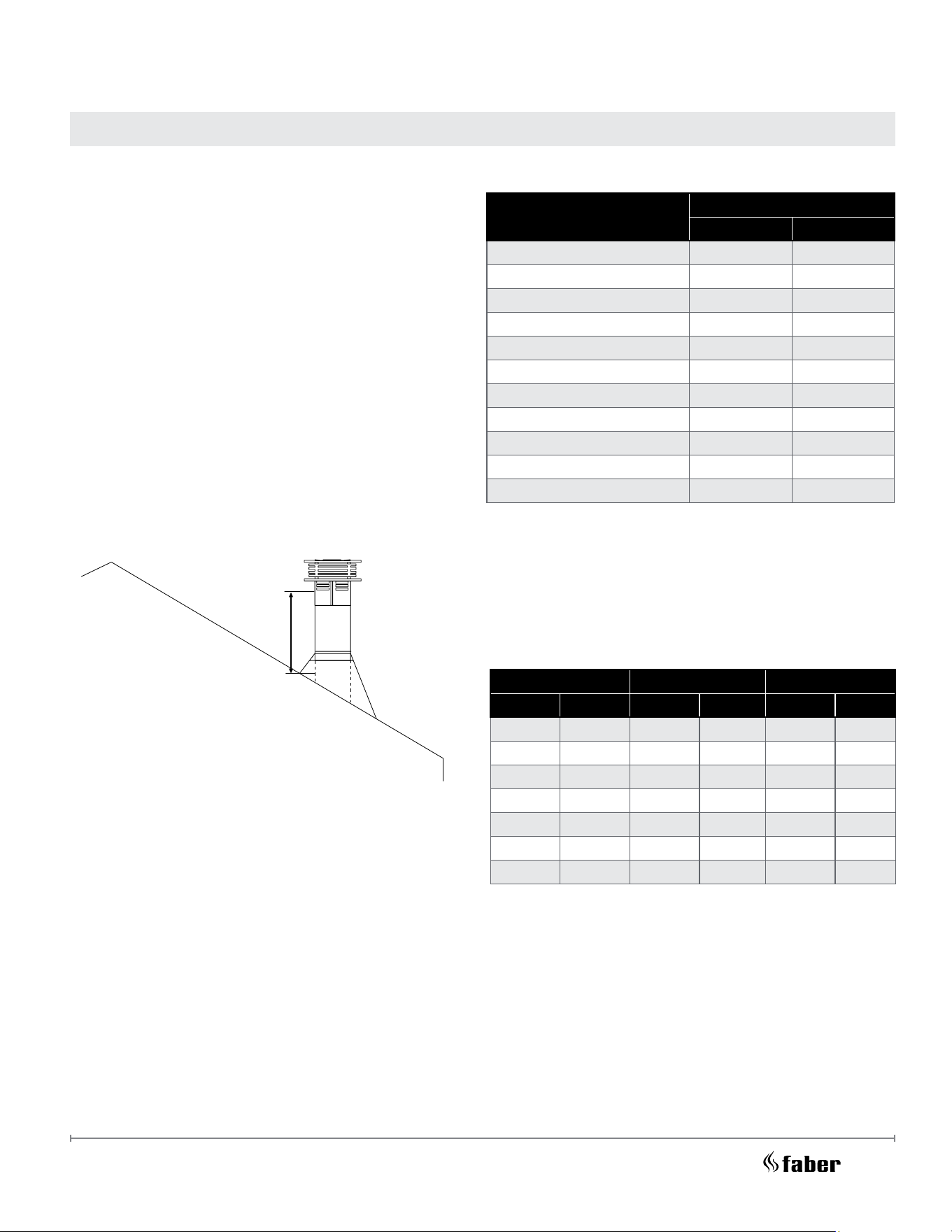
34
Unit Installation with Vertical Termination
Galvanized pipe is desirable above the rooine
due to its higher corrosion resistance. Continue
to add pipe sections through the ashing until
the height of the vent cap meets the minimum
height requirements specied in this manual or
local codes. Note that for steep roof pitches, the
vertical height must be increased.
7. Ensure vent is vertical and secure the base
of the ashing to the roof with roong rails,
slide storm collar over the pipe section and
seal with a mastic.
8. Install the vertical termination cap by twist
locking it.
!
NOTE: Any closets or storage spaces, which
the vent passes through must be enclosed.
Roof Pitch
Minimum Vent Height
Feet Meters
at to 7/12 2 0.61
over 7/12 to 8/12 2 0.61
over 8/12 to 9/12 2 0.61
over 9/12 to 10/12 2 ½ 0.76
over 10/12 to 11/12 3 ¼ 0.99
over 11/12 to 12/12 4 1.22
over 12/12 to 14/12 5 1.52
over 14/12 to 16/12 6 1.83
over 16/12 to 18/12 7 2.13
over 18/12 to 20/12 7 ½ 2.29
over 20/12 to 21/12 8 2.44
A poor draft, or down drafting can result from high wind
conditions near big trees or adjoining roof lines, in these
cases. Increasing the vent height may solve the problem.
Oset Pipe Length Height
inches mm inches mm inches mm
4 ¾ 121 0 0 13 ¼ 337
9 229 6 152 17 ½ 445
11 ¼ 286 9 229 19 ½ 495
13 ¼ 337 12 305 21 ¾ 552
21 ¾ 552 24 610 30 ¼ 768
30 ¼ 768 36 914 39 991
38 965 48 1219 47 1194
Vent
Height
See DuraVent manufacturer's guidelines for minimum
cutout dimensions or frame openings around wall
venting. Make sure clearances to combustible material
are maintained based on vent part used.
!
NOTE: Cutout sizes vary according to the DuraVent
part number used.
Diagram 4
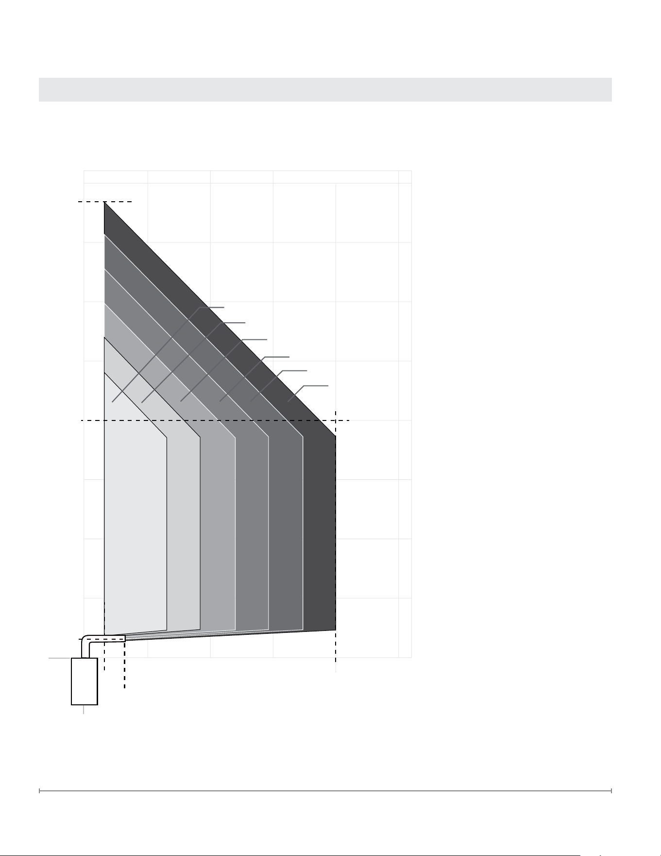
35
FaberFires.com
Vent Termination
1-6 elbow zone
1-5 elbow zone
1-4 elbow zone
1-3 elbow zone
1-2 elbow zone
1 elbow zone
0°
10' 15' 20' 25'
2'
(24")
1 ½'
(18")
(20")
38 ½'
(462")
5'
5'
10'
15'
20'
30'
35'
25'
40'
V
H
0°
Base of
air collar
V+H ≤ 40 ft.
H ≤ 20 ft.
V + H are measured from
the centre of the vent elbows.
Elbows are considered as 90°.
Two 45° elbows = One 90° elbow.
Minimum Venting Requirements
Allowable Vent Congurations for Horizontal Vent Termination
(For Models FMG3326F, FMG3726L, FMG3726R, FMG4126B ONLY)
Vertical Rise (V)
Horizontal Run (H)
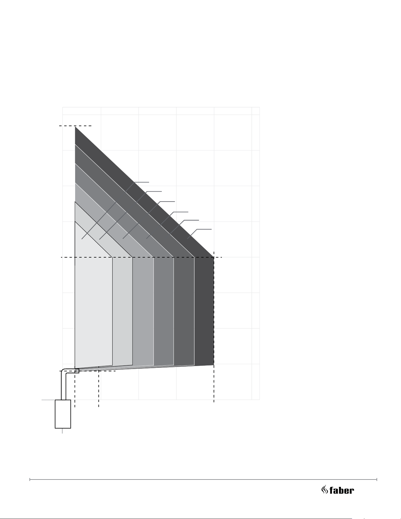
36
V+H ≤ 40 ft.
H ≤ 20 ft.
V + H are measured from
the centre of the vent elbows.
Elbows are considered as 90°.
Two 45° elbows = One 90° elbow.
1-6 elbow zone
1-5 elbow zone
1-4 elbow zone
1-3 elbow zone
1-2 elbow zone
1 elbow zone
4'
(48")
38 ½'
(462")
5'
10'
15'
20'
30'
35'
25'
40'
V
10' 15' 20' 25'
4 7⁄8'
(24")
1 ½'
(18")
5'
H
0°
0°
Base of
air collar
Allowable Vent Congurations for Horizontal Vent Termination
(For Models FMG4326F, FMG4726L, FMG4726R, FMG5126B ONLY)
Vertical Rise (V)
Horizontal Run (H)
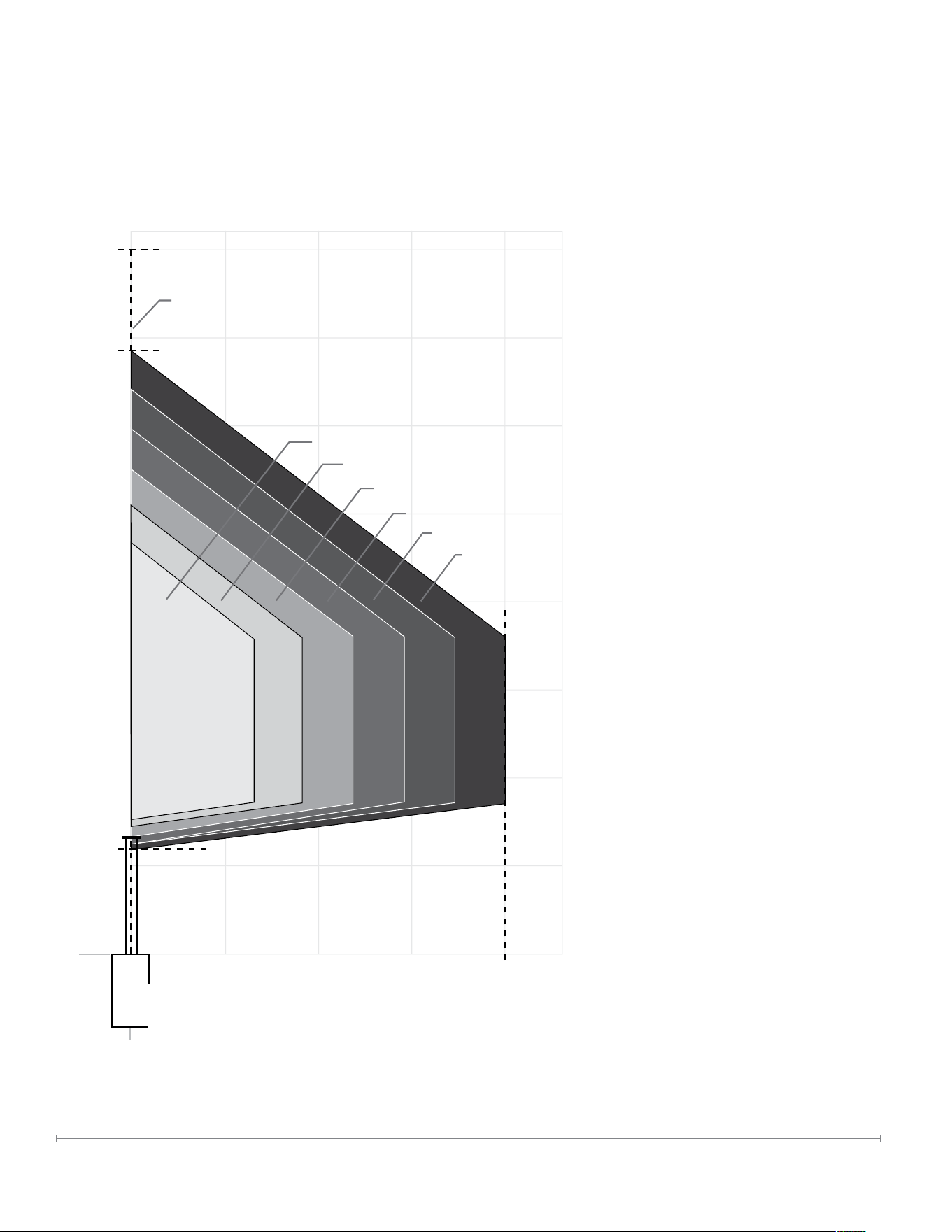
37
FaberFires.com
Vent Termination
2-7 elbow zone
2-6 elbow zone
2-5 elbow zone
2-4 elbow zone
2-3 elbow zone
2 elbow zone
0 elbow
zone
V+H ≤ 40 ft.
H ≤ 20 ft.
V + H are measured from
the centre of the vent elbows.
Elbows are considered as 90°.
Two 45° elbows = One 90° elbow.
ALL APPLIANCES
(NATURAL GAS ONLY)
10' 15' 20'5'
5'
6'
10'
15'
20'
25'
30'
35'
40'
0°
0°
Base of
air collar
Note: A 6' (1.83 m) minimum
vertical rise is considered the
minimum practical dimension for
the specic appliance enclosure
and a minimal building structure.
However, a greater minimum
vertical rise may be needed
to suit the specic application
constraints or local codes and /
or regulatory requirements.
Allowable Vent Congurations for Vertical Vent Terminations
(For All Models)
Vertical Rise (V)
Horizontal Run (H)

38
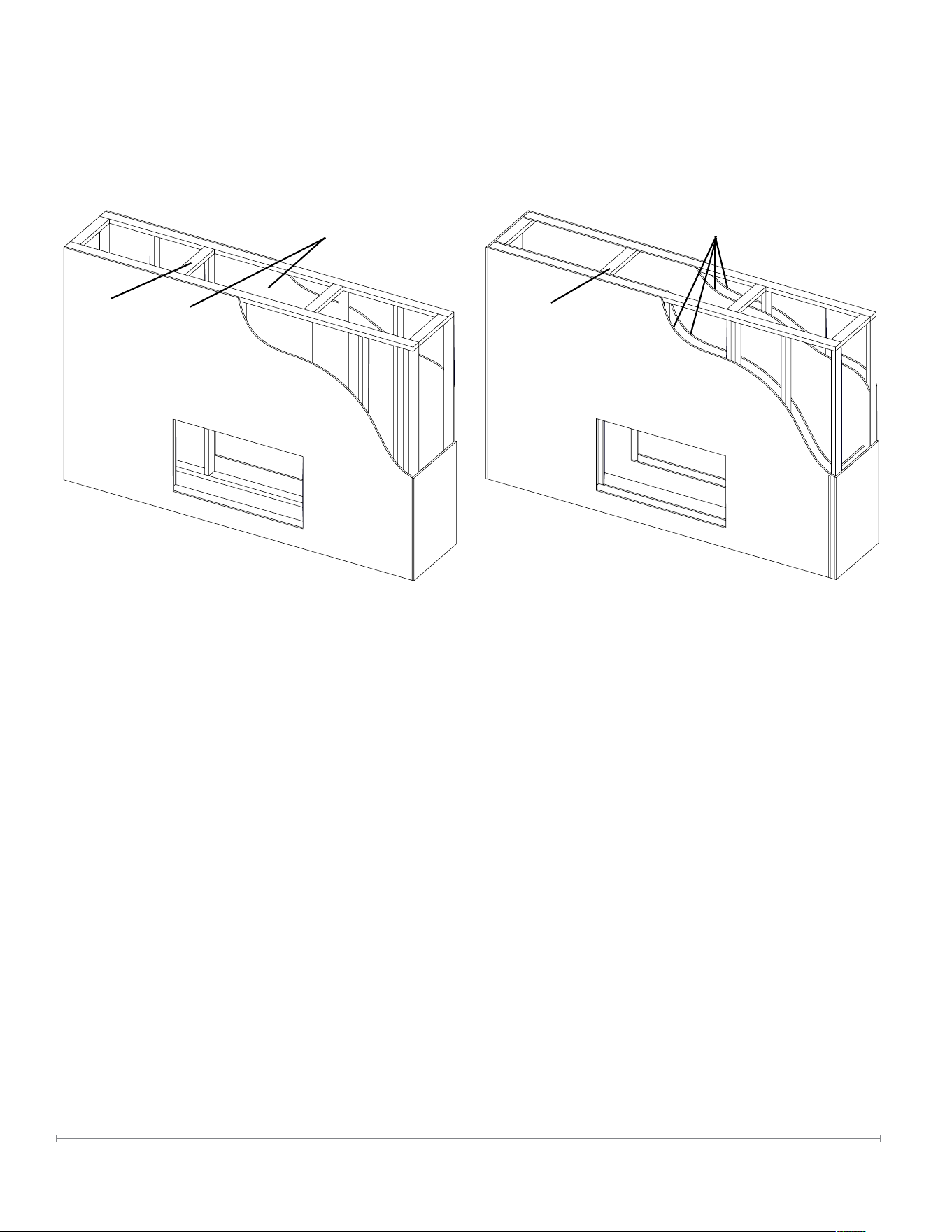
39
FaberFires.com
Non-Combustible Framing Combustible Framing
A layer of non-combustible material (⅝" Type X re
resistant drywall or ½" cement board) is required on
the interior (cladding the entire inner cavity/chase)
and exterior of the wood framing. This provides
heat protection for both the combustible framing
and the nishing material.
A clearance of 1/2" is needed between the non-
combustible material and the rebox.
A layer of non-combustible material (⅝" Type X re
resistant drywall or ½" cement board) is required
on the exterior of the metal framing. This provides
heat protection for the nishing material.
A layer of non-combustible material (⅝" Type
X re resistant drywall or ½" cement board) is
recommended on the inside of the chase when a
television (or similar element) will be installed above
the replace. See ‟Television Mounting Information″
for more details. A clearance of 1/2" is needed
between the non-combustible material and the
rebox.
Non-Combustible Material
(⅝" Type X Fire Resistant
Drywall or ½" Cement Board)
Metal Studs
Wood Studs
Non-Combustible Material
(⅝" Type X Fire Resistant
Drywall or ½" Cement Board)
Chase and Framing Installation and Planning
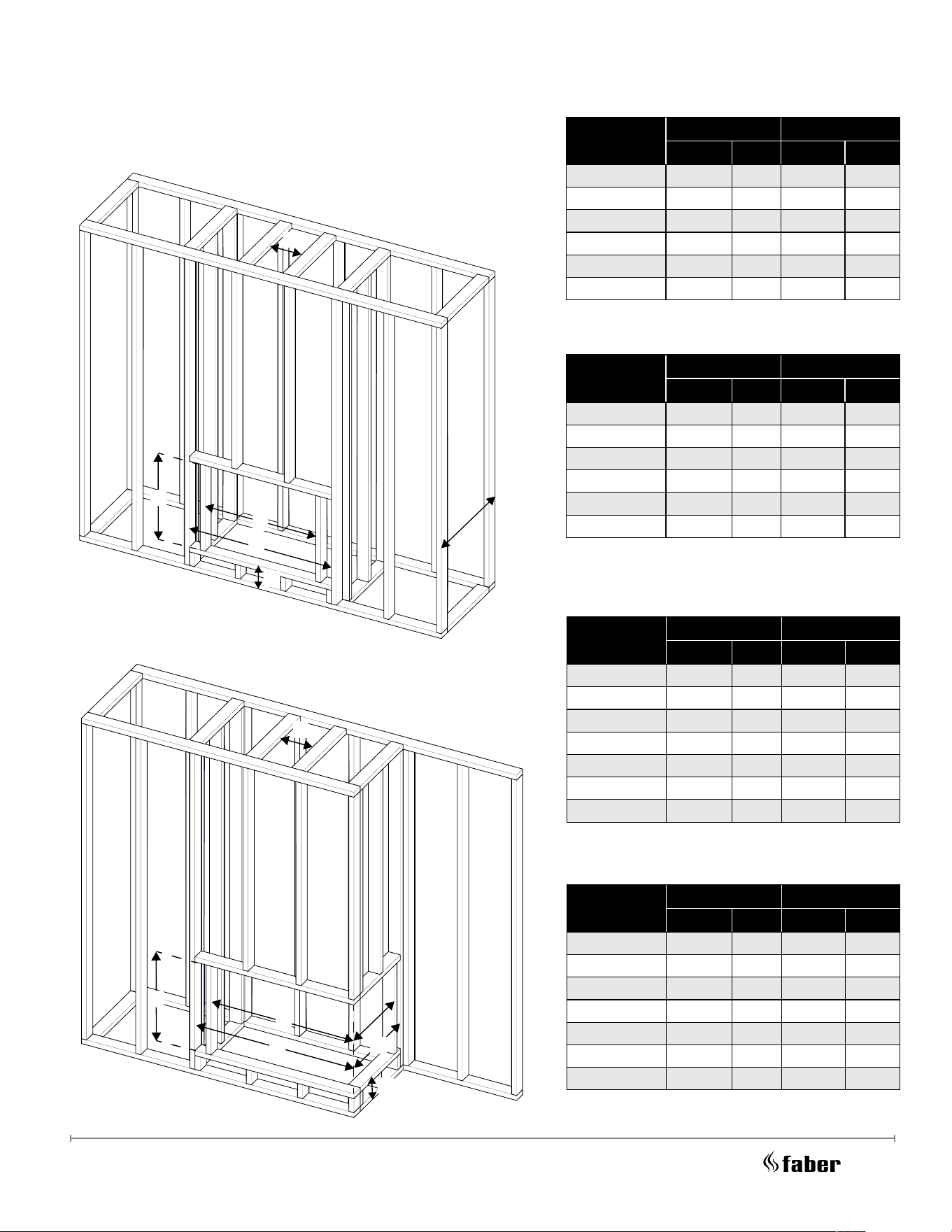
40
Reference
Wood framing Metal Framing
inches mm inches mm
A
27 686 27 686
B
44 1/4 1124 43 1/4 1099
C
33 3/4 857 33 3/4 857
D
28 1/2 724 27 1/2 699
F
10 254 10 254
G (min.) 7 1/4 184 7 1/4 184
Reference
Wood framing Metal Framing
inches mm inches mm
A
27 686 27 686
B
47 7/8 1216 46 7/8 1191
C
42 5/8 1083 42 1/8 1070
D
28 1/2 724 27 1/2 699
E
23 1/8 587 22 5/8 575
F
10 254 10 254
G (min.) 7 1/4 184 7 1/4 184
Reference
Wood framing Metal Framing
inches mm inches mm
A
27 686 27 686
B
57 3/4 1467 56 3/4 1441
C
52 1/2 1334 52 1321
D
28 1/2 724 27 1/2 699
E
23 1/8 587 22 5/8 575
F
10 254 10 254
G (min.) 7 1/4 184 7 1/4 184
Reference
Wood framing Metal Framing
inches mm inches mm
A
27 686 27 686
B
54 1/8 1375 53 1/8 1349
C
43 5/8 1108 43 5/8 1108
D
28 1/2 724 27 1/2 699
F
10 254 10 254
G (min.) 7 1/4 184 7 1/4 184
Single-Sided Installation
A
B
DD
G
F
C
Two-Sided Installation
G
F
EE
A
B
C
D
FMG3326F
FMG4326F
FMG3726L/FMG3726R
FMG4726L/FMG4726R
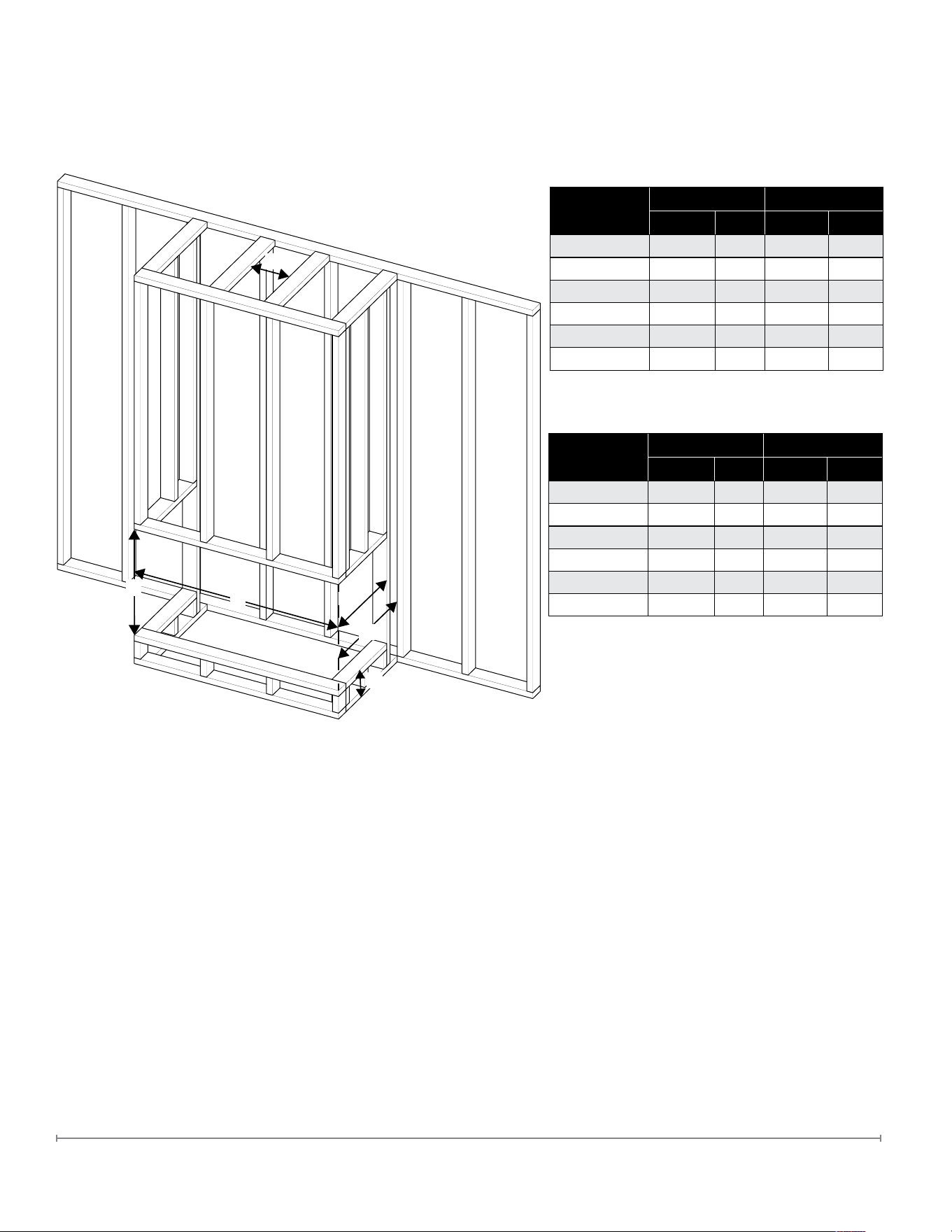
41
FaberFires.com
Three-Sided Installation
Dimension breakdowns:
Dimension A – Metal: replace height + 1/4" (6 mm) (for maneuvering)
Dimension A – Wood: replace height + 1/4" (6 mm) (for maneuvering)
Dimension B – Metal: replace width+ 5/8" (15 mm)
Dimension B – Wood: replace width + 5/8" (15 mm) + 5/8” (15 mm) (type X drywall on either side)
Dimension D – Metal: replace depth – 1/2" (12 mm) (drywall lip)
Dimension D – Wood: replace depth – 1/2" (12 mm) (drywall lip) + 5/8" (15 mm) (type X drywall)
Dimension F – Metal: pipe diameter + 1" (25 mm) right side clearance + 1" (25 mm) left side clearance
Dimension F – Wood: pipe diameter + 1" (25 mm) right side clearance + 1" (25 mm) left side clearance
Dimension G – Metal: height from oor to bottom trim
Dimension G – Wood: height from oor to bottom trim
Chase and Framing Installation and Planning
FMG4126B
FMG5126B
Reference
Wood framing Metal Framing
inches mm inches mm
A
27 686 27 686
B
51 1/2 1308 50 1/2 1283
D
28 1/2 724 27 1/2 699
E
23 1/8 587 22 5/8 575
F
10 254 10 254
G (min.) 7 1/4 184 7 1/4 184
Reference
Wood framing Metal Framing
inches mm inches mm
A
27 686 27 686
B
61 3/8 1559 60 3/8 1534
D
28 1/2 724 27 1/2 699
E
23 1/8 587 22 5/8 575
F
10 254 10 254
G (min.) 7 1/4 184 7 1/4 184
A
B
D
EE
G
F
42
FIRE HAZARD: DO NOT apply combustible materials beyond the minimum clearances. Comply with all minimum
clearances to combustibles as specied in this manual.
Non-Combustible Materials Specication
Non-combustible materials are those which will not ignite and burn. These are materials consisting entirely of steel,
iron, brick, tile, concrete, slate, glass or plasters, or any combination thereof. Materials that are reported as passing
ASTM E 136, Standard Test Method for Behavior of Materials in a Vertical Tube Furnace at 750 °C shall be considered
non-combustible materials. Approved non-combustible cement board must be at least ½" (13 mm) thick.
Non-combustible material may be installed on the replace frame to cover the metal part as detailed in the
installation examples and clarications only if there is no weight transfer to the replace. Facing and/or nishing
materials must never overhang into the glass opening.
DO NOT connect materials to or drill into the metal replace frame. This can result in excessive heat transfer and/or
damage to the replace and surrounding materials.
All joints between the nished wall sheathing and the appliance must be sealed with non-combustible materials.
Material Specications
Examples of non-combustible materials that can be used:
• Skamol Skamotec
• Promat PROMAFOUR System ½" (12 mm), ⅝" (15 mm), ¾" (18 mm)
• James Hardie - Hardiebacker
®
½" Cement Board
• ⅝" (15 mm) Type X re rated drywall. Type X gypsum board must comply with ASTM C1396 specication. Type
X re rated gypsum board can be used around the replace or at the back as a non-combustible material.
Combustible Materials Specication
Combustible materials made of or surfaced with wood, compressed paper, plant bers, plastics, or other
materials that can ignite and burn, whether ame-proofed or not, or plastered or un-plastered shall be considered
combustible materials.
Clearances
!
WARNING
43
FaberFires.com
Clearances
• Never allow the vent to run downward. A downward slope can trap heat and become a possible re hazard.
• Maintain vent clearance to combustibles as detailed above.
• DO NOT pack airspace with insulation or other materials. Failure to keep insulation or other materials away from
vent pipe could cause overheating and re.
• This replace is not designed to be load-bearing or support weight of any architectural framing. All framing
should be self-supported, supported by the back wall, side wall, or ceiling. Attempting to
mount framing to a replace subjects’ glass to unsupported weight and could result in damage to replace or
breakage of glass. Improper framing or mounting to unit will void product warranty. Please consult Faber directly
for additional questions or concerns about framing options.
Minimum Combustible Clearances from Vent Pipe
Horizontal Vent Pipe Clearances
A minimum clearance of 3" (76 mm) to the top and 1" (25 mm) to the sides and bottom of the vent pipe on all
horizontal runs, to combustibles, is required.
Vertical Vent Pipe Clearances
A minimum of 1" (25 mm) around the vent pipe on all vertical runs to combustibles is required, except for
clearances in appliance enclosures.
Horizontal Vents must have a minimum 1/4" (6 mm) rise per 1-foot run towards the termination.
!
WARNING
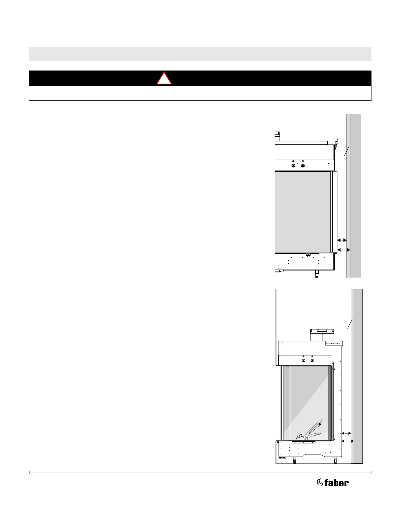
44
All materials inside the chase and above the replace must be non-combustible or covered combustible only.
Clearance to Metal Framing
The minimum clearance to metal framing is ½" (13 mm).
Metal Studs
Clearance to side stud: ½" (13 mm)
Clearance to Non-Combustible Back Wall: 2" (51 mm) min.
Wood Studs with Metal Header
Clearance to Non-Combustible Board (SIDES): ½" (13 mm) min.
Clearance to Non-Combustible Board (BACK WALL): 2" (51 mm) min.
Clearance to Covered Combustible Stud (WOOD): 2-½" (64 mm) min.
Clearance to sides and back covers - Non-combustible
The minimum clearance from the back and sides of the replace to any
non-combustible covered material (1/2" (13 mm) cement board or 5/8"
(16 mm) Type X drywall) is 2" (51 mm). This clearance allows for proper
airow.
Clearance to sides and back - Covered combustible
Combustible material at the back or sides of the replace, MUST be
covered with non-combustible material that is at least ½" thick.
Covered wood can be placed a minimum of 2" (51 mm) away (including
non-combustible covering) from the sides and back.
Example: A non-combustible cement board is placed 2" (51 mm) from
the back of the replace. The cement board used is ½" (13 mm) thick.
Combustible material can be used behind cement board as it is a total of
2-½" (64 mm) away from the back of the replace and is covered with a
non-combustible material.
Clearance to Sides and Back - Combustible
Minimum clearance to combustible material at the back or sides of the
replace, below the non-combustible line is ½" (13 mm) from sides, and
2" (51 mm) over covered combustibles. Please note this does not include
minimum clearance directly above the replace inside the chase.
Wood Stud
Non-Combustible MaterialNon-Combustible Material
2"
2 ½"2 ½"
Chase Clearances
SIDE WALL
BACK WALL
Non-Combustible MaterialNon-Combustible Material
½"½"
1"1"
!
WARNING
FRONT VIEW
SIDE VIEW
Wood Stud
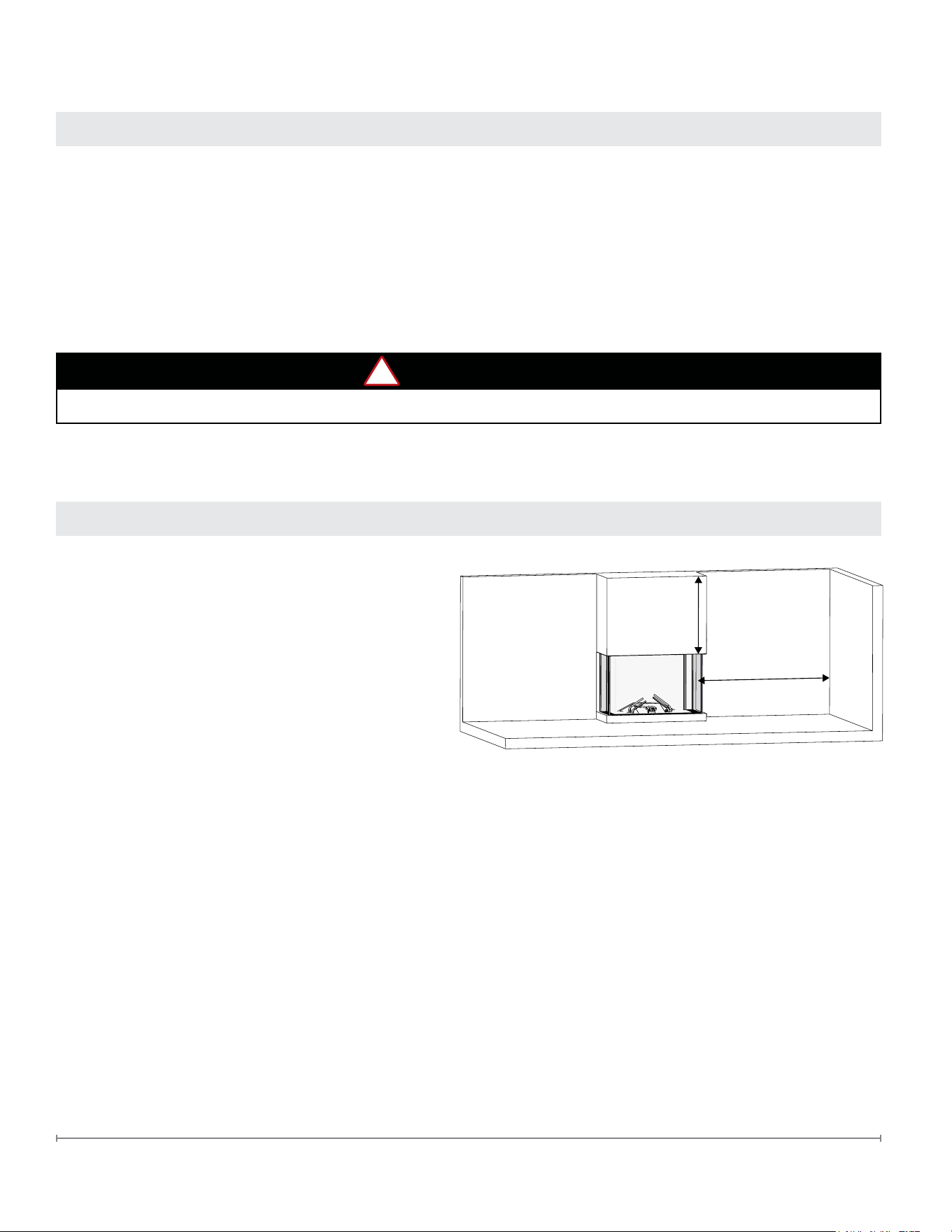
45
FaberFires.com
Clearances
Chase Ceiling
The inner top portion of the chase must be covered with non-combustible material (restop). No exposed
combustible materials are permitted inside the chase.
Floor Clearance
The minimum clearance to the oor is 4-¼" (108 mm), which is provided by the minimum height of the feet. Do not
remove the feet or install the appliance in a manner that would bypass this minimum elevation.
!
NOTE: Install appliance on hard metal, cement board, drywall or wood surfaces, extending full width and depth.
Additional Clearances
Ceiling Clearance
The minimum ceiling height required for installation of
all models is 96" (2.4 m).
The minimum clearance required from the top of the
glass to the ceiling is 60" (1.52 m).
The heat release above the replace is critical
for keeping the chase and surrounding walls at a
relatively low temperature.
Adjacent Wall Clearance
The minimum distance to any side adjacent wall is 7"
(178 mm) from the glass for all models.
Ceiling Ceiling
Clearance Clearance
Min. 60" Min. 60"
(1.52 m)(1.52 m)
Adjacent Wall Adjacent Wall
Min. ″ from GlassMin. ″ from Glass
Front Clearance
Do not put furniture or any combustible objects within 36" (0,9 m) of glass front of appliance.
DO NOT install directly on carpeting, vinyl, or any combustible material other than wood.
!
WARNING
Chase Clearances
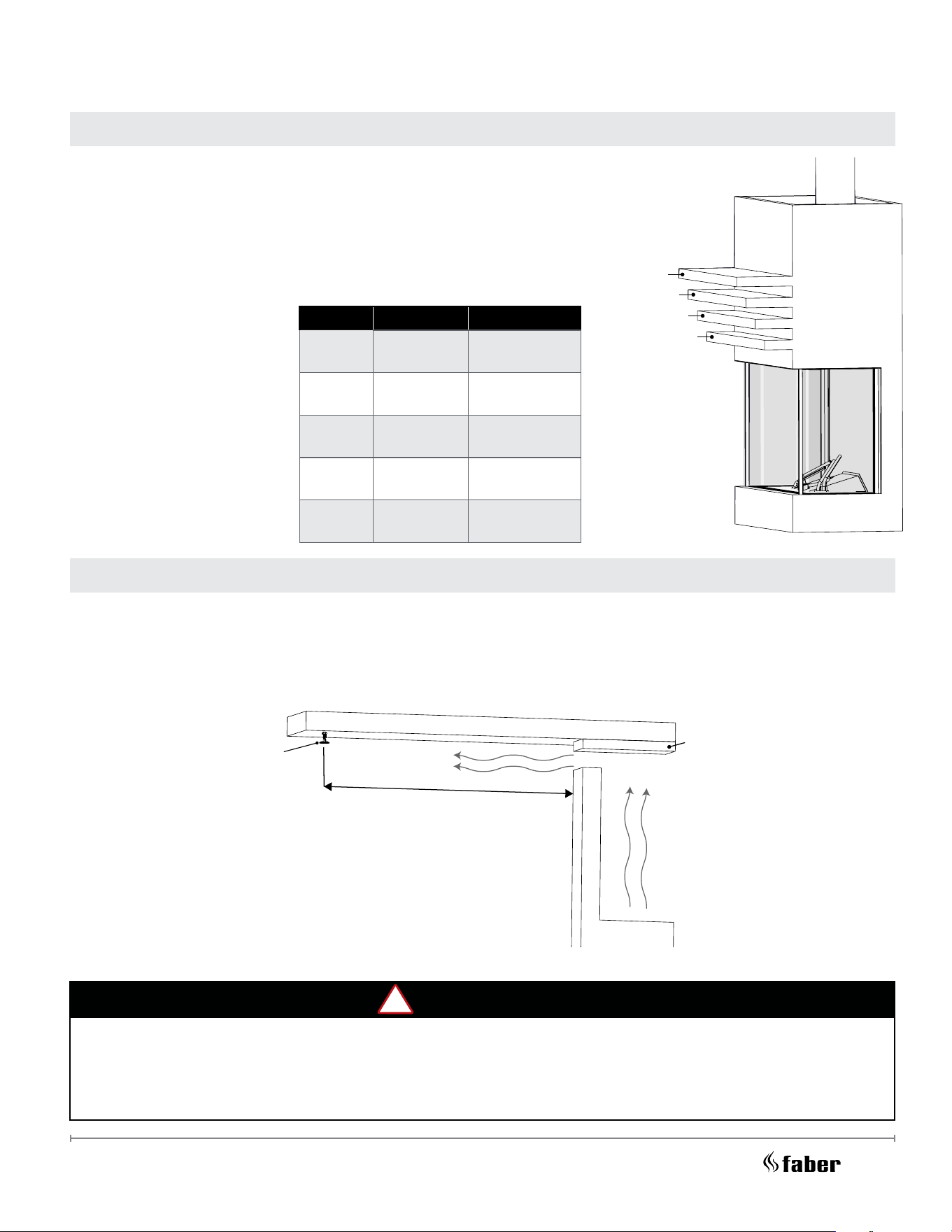
46
The necessary clearance for a mantel made of combustible
materials (e.g., wood) varies according to the mantel depth and
height. Use the following table and illustration for information on
mantel clearance requirements for mantels made of combustible
material installed less than 10" (254 mm) above the top of the
replace. Do not anchor any mantel or shelf to the replace.
Only use metal studs above the replace as anchor points.
Mantel Clearance
A
B
C
D
Ref. Height Max. Depth
−
> 10"
> 254 mm
No maximum
A
10"
254 mm
12"
305 mm
B
6"
152 mm
6"
152 mm
C
4"
101 mm
4"
101 mm
D
2"
51 mm
1"
25 mm
In a situation where a sprinkler head is installed within proximity to a heat release, the diagram below MUST be
followed. The distance between the sprinkler head & heat release opening cannot be less than 60" (1524 mm) in
length at every point from the origin of the heat release. You must also verify the sprinkler head sensor is set to
the proper heat setting so it does not activate when the room heats up from the replace being operated normally.
Please follow local building code to determine what temperature setting is relevant for your installation.
Clearance to Sprinkler
Vaulted ceilings can create a channel that funnels hot air directly towards a sprinkler head placed at the
proper distance from heat release, as stated above. If sprinkler head sensor is not rated for high heat, it could
potentially set o the sprinkler system inadvertently. Please work with builder & inspector to verify your sprinkler
system is properly set to accommodate higher temperatures & is not set up in a heat channel.
60" Minimum
(1.52m)
Ceiling
Sprinkler Head
Fire stop
!
WARNING

47
FaberFires.com
Finishing Around Front of the Fireplace
Non-combustible nishing material (such as ½" cement board, brick, stone, tile, minimum 5/8" (13 mm) Type X re
rated drywall) MUST be used to nish around the front of the appliance. Covered combustible material, can be used
to nish around the replace, if the proper distance from the replace is maintained.
Non-Combustible nishing material must protect any combustible nishing material that is installed above replace
glass. See ‟Mantel Clearance” for requirements.
DO NOT connect materials to or drill into the metal replace frame. This can result in excessive heat transfer
and/or damage to the replace and surrounding materials.
Clearances

48
This replace requires one or more heat release outlet(s) located above the replace to allow warm air to ow back
into the room and keep the replace wall cool.
The total heat release outlet area must be at least 200 square inches (1290 cm²). A larger heat release outlet area
is recommended where the application permits it, as this will help reduce the temperature of surrounding wall. The
heat release must not be vented outdoors, as this would cause the replace to be exposed to outdoor elements.
!
NOTE: The recommended minimum dimensions provided for the heat release are measured for open
airspace. When using accessories such as vent grilles, the opening must be made larger to account for the
reduced open airspace.
The outlet for heat release from the wall enclosure MUST remain open. The outlet must be at the top part of
the enclosure but not necessarily at the front, so long as the measurements below are maintained. Heat release
openings can be installed at the front, on the sides (one on each side), on the back, or on top (in case of a drop wall
design, where the top of the wall does not meet the ceiling) of the enclosure.
The top of the heat release outlet(s) must be between 1" - 3" (25 mm - 76 mm) down from the re stop or ceiling.
For installations where the top of a heat release outlet is less than 3", it is recommended to use re-rated board on
the ceiling. A non-combustible re stop must be placed at the top of the inside of the chase and must be framed
in a way that does not allow any pockets of heat to be formed. The heat should be able to rise to the re stop and
freely ow through the vent to enter the room.
This replace requires a cool air intake located below the replace.
The total air intake area must be at least 100 square inches (645 cm²).
!
NOTE: The recommended minimum dimensions provided for the air intake are measured for open airspace.
When using accessories such as vent grilles, the opening must be made larger to account for the reduced
open airspace.
The air intake opening can also be used as an access door to the gas valve, if it meets both of the size requirements
for the access door and the air intake opening. The air intake opening can be installed at the sides of the enclosure
(one on each side), or at the front.
Heat Releases
Air Intake
Heat Releases and Air Intakes
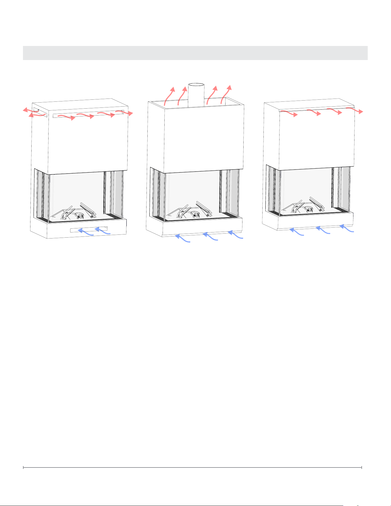
49
FaberFires.com
Classic Registers
Openings at the front, sides, or back
(pick one or more) can be covered
with vent registers. It is possible to
heat multiple rooms this way.
Drop Wall
The wall does not reach the ceiling
and is left open on top.
Shadow Line
A recess hides the opening at the
top for a heat release and/or a at the
bottom for air intake.
Examples of Heat Releases and Air Intakes
Heat Releases and Air Intakes
50
This replace design directs the heat from the replace into the replace chase to be released from the top heat
release outlet. The design allows for a relatively low temperature on the external wall above the replace.
Follow the charts and instruction below for suggested installation of a television above the replace
• Please note that electric wiring used for the television must be insulated for heat when installed inside the
chase above the replace.
• It is critical that wiring insulation does not obstruct the hot air ow from going to the top part of the chase to be
released back to the room through the heat release outlet.
• All wires MUST be secured and anchored to the frame to prevent any possibility of wires dropping on top of the
replace.
• A double layer of drywall is recommended in the area behind the TV to allow cables and other related materials
to be installed without blocking hot air ow. Use non-combustible material for double wall.
• Wires should be inserted into the recess from the top or sides in order to avoid proximity to the replace heat
release outlet or air intake inlet.
• Placing insulation above the replace may result in a re hazard. Airow above the replace should remain open
to allow heat to be released from the top of the chase.
• When installing a television above the replace without recessing it, a mantel must be installed between the top
of the replace and the bottom of the television to avoid exposing the television to excessive heat.
• To reduce the amount of heat around and below the television, increase the size of the heat release outlet as
much as the installation will allow. ALWAYS follow minimum heat release requirements.
• See images for information on minimum clearances for dierent TV installation options. All dimensions shown
are minimum dimensions. Hot air ow inside the chase (marked in red arrows) should be maintained and free
from obstruction to allow heat to release freely at the top of the chase.
Please note that most television manufacturers and manuals will instruct the owner not to install television above
or near a replace. Mounting a television above the replace is based on the owner’s decision and responsibility.
Faber will not be held liable for any adverse eects on a TV, artwork or other equipment located near the
appliance. It is the customer’s or contractor responsibility to verify that their TV or artwork can withstand the wall
temperatures at the installation site.
Maintain open airow between the replace and wall covers. Make sure cables or any other materials are not
blocking hot airow.
Television Mounting Information
!
WARNING
!
WARNING
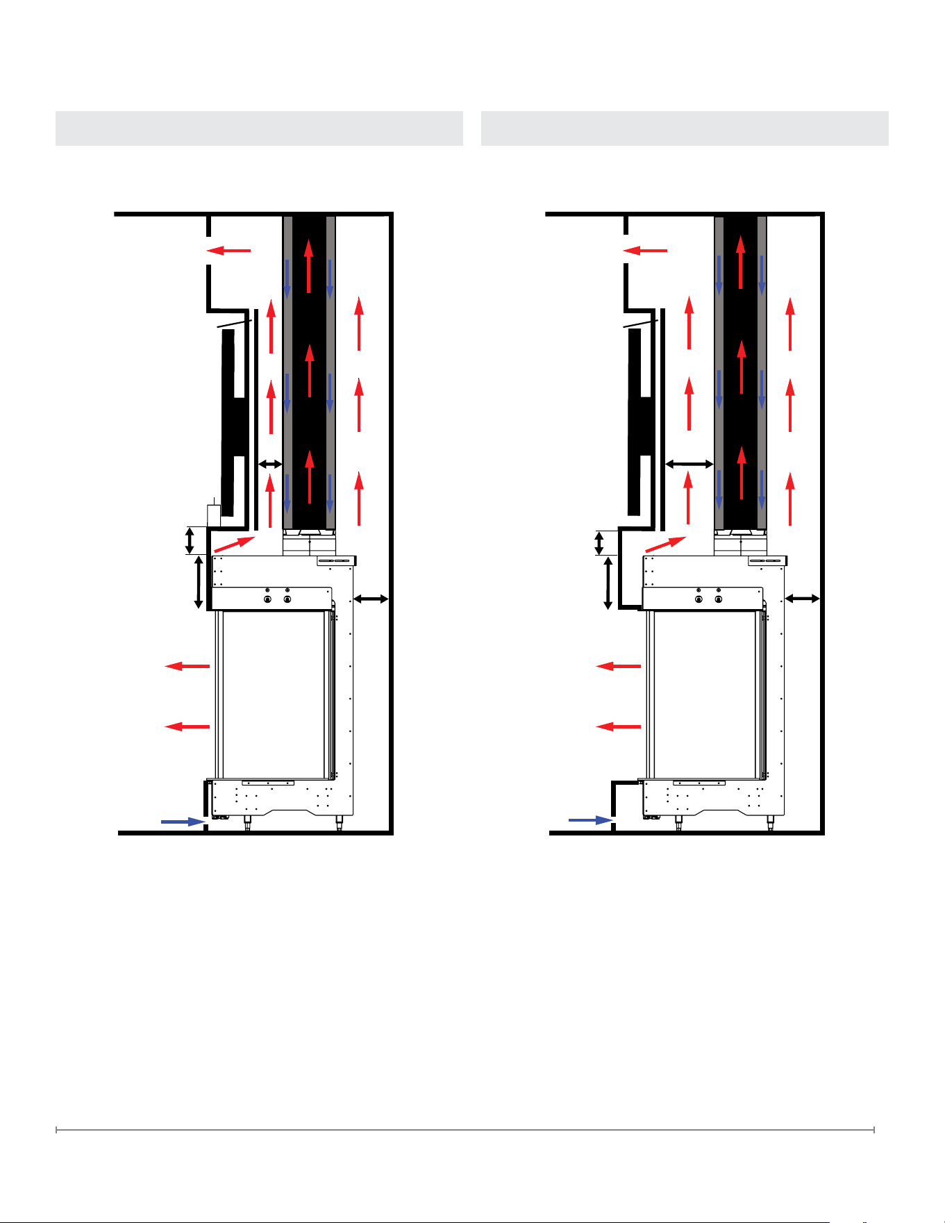
51
FaberFires.com
Television Mounting Information
Flat with Recessed TV Recessed with recessed TV
1"
1"
25mm25mm
25 mm25 mm
51 mm51 mm
51 mm51 mm
51 mm51 mm
51 mm51 mm
203 mm203 mm
203 mm203 mm
127 mm127 mm
25mm25mm
1"
2"2"
2"2"
2"2"
8"8" 8"8"
2"2"
5-¼" 5-¼"
maximum maximum
recessrecess
TV cables can be TV cables can be
placed between placed between
noncombustible noncombustible
board layersboard layers
Heat ReleaseHeat Release
Heat ReleaseHeat Release
Air IntakeAir Intake Air IntakeAir Intake
TV cables can be TV cables can be
placed between placed between
noncombustible noncombustible
board layersboard layers
* All measurements shown are
minimum requirements.
* All measurements shown are
minimum requirements.
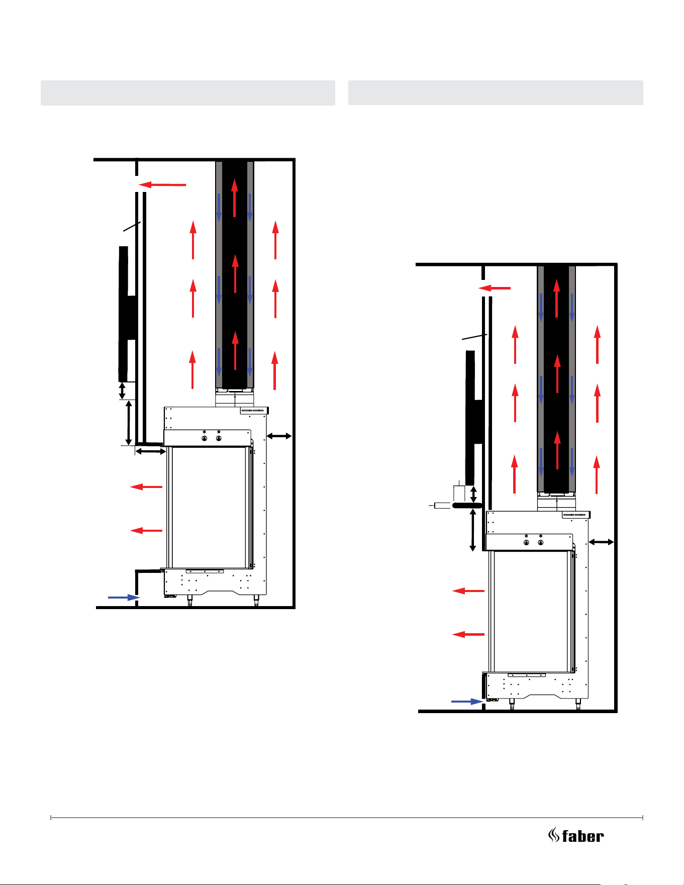
52
25 mm25 mm
25 mm25 mm
51 mm51 mm
51 mm51 mm
51 mm51 mm
51 mm51 mm
203 mm203 mm
203 mm203 mm
127 mm127 mm
1"
2"2"
2"2"
2"2"
2"2"
8"8"
8"8"
1"
Heat ReleaseHeat Release
Heat ReleaseHeat Release
Air IntakeAir Intake
Air IntakeAir Intake
TV cables can be TV cables can be
placed between placed between
noncombustible noncombustible
board layersboard layers
TV cables can be TV cables can be
placed between placed between
noncombustible noncombustible
board layersboard layers
5-¼" 5-¼"
maximum recessmaximum recess
Television Install Without Recess
Television Installed Flush Above Fireplace
Minimum Requirements for Installing a Television
Without a Recess:
• The TV must be at least 11" (280 mm) total above
the glass of the replace.
• A mantel at least 1" (25 mm) thick and 6" (152 mm)
deep should be installed a minimum of 8" (203 mm)
above the glass.
• The TV must be at least 2" (51 mm) above the
mantel and 1" back from the edge of the mantel.
* All measurements shown are
minimum requirements.
* All measurements shown are
minimum requirements.
53
FaberFires.com
1. Move the appliance into position and secure it to the wall using the back or side mount.
2. Install a manual gas valve before the connection to the replace appliance automatic valve.
3. Connect the gas line to the replace. The appliance is designed to accept a ½" (13 mm) gas supply.
4. Connect the gas supply in accordance to local codes, CAN/CSA-B149.1 in Canada or to the current National
Fuel Gas Code, ANSI 2223.1 / NFPA 54 in the United States.
5. Check for gas leaks using non-corrosive commercially available leak-check solution before operating the gas
appliance.
6. Measure and document gas pressure below:
Inlet ___ W.C. Burner (Manifold) ___ W.C. Ensure the Min/Max inlet pressure matches the table below.
7. Verify minimum pressures when other household gas appliances are operating.
8. Lighting the replace for the rst time may take some time until the line is purged.
General
!
WARNING
RISK OF FIRE OR EXPLOSION!
!
WARNING
RISK OF FIRE OR EXPLOSION!
• All gas handling and installation should be performed by a qualied service technician or installer.
• Gas build-up during line purge could ignite. Ensure adequate ventilation. Ensure there are no ignition sources,
sparks, or open ames.
• Do not change the gas valve setting! The replace gas valve has been preset at the factory.
• Installing an external manual gas valve before connection to the replace is necessary.
• Make sure to check for gas leaks before lighting the replace for the rst time. Do not use an open ame to
check for gas leaks.
High pressure will damage valve. Low pressure could cause explosion.
This appliance and its individual shut o valve must be disconnected from gas supply piping system during any
pressure testing of that system at test pressures more than ½ psig (3.5 kPa).
This appliance must be isolated from the gas supply piping system by closing its individual manual shut o valve
during any pressure testing of the gas supply piping system at test pressures equal to or less than 1/2 psig
(3.5 kPa).
Have the gas supply line installed in accordance with local codes, if any. If not available, follow ANSI 223.1.
Installation should be done by a qualied installer approved and/or licensed as required by the locality (In the
Commonwealth of Massachusetts Installation must be performed by a licensed plumber or gas tter).
!
NOTE: Do not place the gas valve or controls above the level of the burner.
Gas Pressure Natural Gas
Inlet Pressure 7.0" W.C
Gas Installation
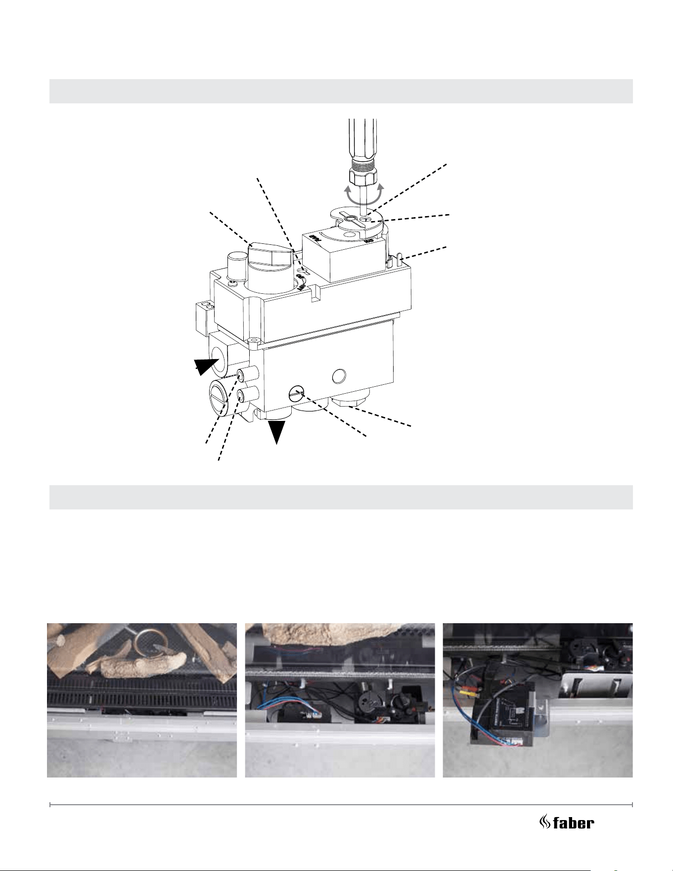
54
Gas Valve
Accessing the Gas Valve and Electronic Receiver
1. Remove the bottom trim and safety screen.
2. Remove the lower grill (pictured).
3. The components can now be accessed for
installation and service.
− +
Main Valve Knob
Side Inlet
Bottom Outlet
Inlet Pressure Tap
Outlet Pressure Tap
Pressure Regulator
or Throttle
(remove plug rst)
Pilot Gas Adjustment
Screw (turn with
screwdriver)
Connection
Piezo Igniter
Tab 2.8×0.8 mm
MANUAL Knob
Magnet Unit
Minimum Rate Orice
Maxitrol GV60 Gas Valve

55
FaberFires.com
This replace is tested and approved for installations at elevations of 0 - 4500 feet (0 - 1372 m) above sea level
using the standard burner orice sizes. At the time of installation, it must be determined if the appliance needs to
be de-rated. Contact your local gas supplier for de-ration requirements for your area.
Derated installation consideration can start at 2000 feet (610 m) above sea level.
At higher elevations, the amount of BTU fuel value delivered must be reduced by either using gas that has been
derated by the gas company or by changing the burner orice to a smaller size as regulated by the local authorities
having jurisdiction and by the (USA) National Fuel Gas Code NFPA 54/ANSI 2223.1 - latest edition or in Canada, the
CAN/CSA-8149.1 code - latest edition.
!
NOTE: This replace has a gas valve and control system that can be stretched up to 46" (1.2 m) from the middle
of the replace and be put next to the access door location.
The access door can be placed on any side of the replace, below the non-combustible line. Do not place the gas
valve or controls above the level of the burner. If the replace is to sit low on the oor, the controls must be placed
outside the non-combustible zone or insulated from the heat of the replace.
The use of a 10" x 10" (254 x 254 mm) access door is highly recommended. If no access door is installed, it is
possible to access the gas valve from inside the replace by removing the outer screen and cover plate.
The access door can also be used as a lower air intake as long as the opening requirements are maintained. See ‟Air
Intake″ section for details.
The access door can be concealed in many ways such as HVAC vent cover, removable tile connected with Velcro
straps and more.
Installation at High Altitude
Gas Valve Access Door
Gas Installation

56
Commonwealth of Massachusetts
For all side wall horizontally vented gas fueled equipment
installed in every dwelling, building or structure used in
whole or in part for residential purposes, including those
owned or operated by the Commonwealth and where
the side wall exhaust vent termination is less than seven
(7) feet above nished grade in the area of the venting,
including but not limited to decks and porches, the
following requirements shall be satised:
1. INSTALLATION OF CARBON MONOXIDE DETECTORS.
At the time of installation of the side wall horizontal
vented gas fueled equipment, the installing plumber
or gastter shall observe that a hard-wired carbon
monoxide detector with an alarm and battery back-up
is installed on the oor level where the gas equipment
is to be installed. In addition, the installing plumber
or gastter shall observe that a battery operated
or hard-wired carbon monoxide detector with an
alarm is installed on each additional level of the
dwelling, building or structure served by the side wall
horizontal vented gas fueled equipment. It shall be
the responsibility of the property owner to secure the
services of qualied licensed professionals for the
installation of hard-wired carbon monoxide detectors
a. In the event that the side wall horizontally vented gas
fueled equipment is installed in a crawl space or an
attic, the hard-wired carbon monoxide detector with
alarm and battery back-up may be installed on the next
adjacent oor level.
b. In the event that the requirements of this subdivision
cannot be met at the time of completion of installation,
the owner shall have a period of thirty (30) days
to comply with the above requirements; provided,
however, that during said thirty (30) day period, a
battery operated carbon monoxide detector with an
alarm shall be installed.
2. APPROVED CARBON MONOXIDE DETECTORS. Each
carbon monoxide detector as required in accordance
with the above provisions shall comply with NFPA 720
and be ANSI/UL 2034 listed and IAS certied.
3. SIGNAGE. A metal or plastic identication plate shall
be permanently mounted to the exterior of the building
at a minimum height of eight (8) feet above grade
directly in line with the exhaust vent terminal for the
horizontally vented gas fueled heating appliance or
equipment. The sign shall read, in print size no less
than one-half (1/2) inch in size, ‟GAS VENT DIRECTLY
BELOW. KEEP CLEAR OF ALL OBSTRUCTIONS”.
4. INSPECTION. The state or local gas inspector of the
side wall horizontally vented gas fueled equipment shall
not approve the installation unless, upon inspection,
the inspector observes carbon monoxide detectors and
signage installed in accordance with the provisions of
248 CMR 5.08(2)(a)1 through 4.
(b) EXEMPTIONS: The following equipment is exempt from
248 CMR 5.08(2)(a)1 through 4:
1. The equipment listed in Chapter 10 entitled ‟Equipment
Not Required To Be Vented” in the most current edition
of NFPA 54 as adopted by the Board; and
2. Product Approved side wall horizontally vented gas
fueled equipment installed in a room or structure
separate from the dwelling, building or structure used
in whole or in part for residential purposes.
(c) MANUFACTURER REQUIREMENTS - GAS EQUIPMENT
VENTING SYSTEM PROVIDED. When the manufacturer
of Product Approved side wall horizontally vented
gas equipment provides a venting system design or
venting system components with the equipment,
the instructions provided by the manufacturer for
installation of the equipment and the venting system
shall include:
1. Detailed instructions for the installation of the venting
system design or the venting system components; and
2. A complete parts list for the venting system design or
venting system.
(d) MANUFACTURER REQUIREMENTS - GAS EQUIPMENT
VENTING SYSTEM NOT PROVIDED. When the
manufacturer of a Product Approved side wall
horizontally vented gas fueled equipment does not
provide the parts for venting the ue gases, but
identies ‟special venting systems”, the following
requirements shall be satised by the manufacturer:
1. The referenced ‟special venting system” instructions
shall be included with the appliance or equipment
installation instructions; and
2. The ‟special venting systems” shall be Product
Approved by the Board, and the instructions for that
system shall include a parts list and detailed installation
instructions.
(e) A copy of all installation instructions for all Product
Approved side wall horizontally vented gas fueled
equipment, all venting instructions, all parts lists
for venting instructions, and/or all venting design
instructions shall remain with the appliance or
equipment at the completion of the installation.
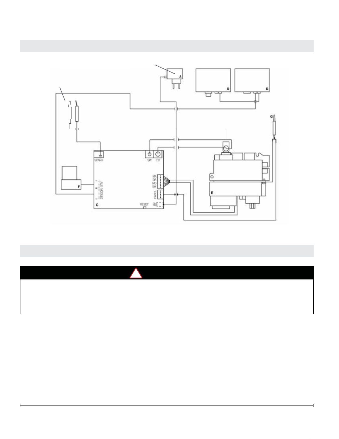
57
FaberFires.com
Wiring Diagram
Power Source
Main adaptor
(Optional -
Batteries can be
used instead)
LED Modules
Thermocouple
interrupter box
Second
Thermocouple
Gas Valve
Receiver Box
Ignitor
Latching
Valve
This appliance must be electrically wired and grounded in accordance with local codes, or in the absence of local
codes, with National Electric Code ANSI/NFPA70-latest edition or the Canadian Electric Code CSAC22.1. A 110–
120 V AC circuit for this product must be protected with ground-fault circuit-interrupter protection, in compliance
with the applicable electrical codes, when it is installed in locations such as in bathrooms or near sinks.
The electrical system can be powered either by plugging the adaptor into a grounded outlet or by installing 4 AA
batteries (alkaline ONLY). If a mains A/C adaptor is not used, battery replacement is recommended at the beginning
of each heating season as part of the yearly service check. The receiver box is equipped with a low battery indicator,
which will beep frequently for 3 seconds when the motor turns.
Electric and Control
!
WARNING
Pilot Burner
Thermocouple
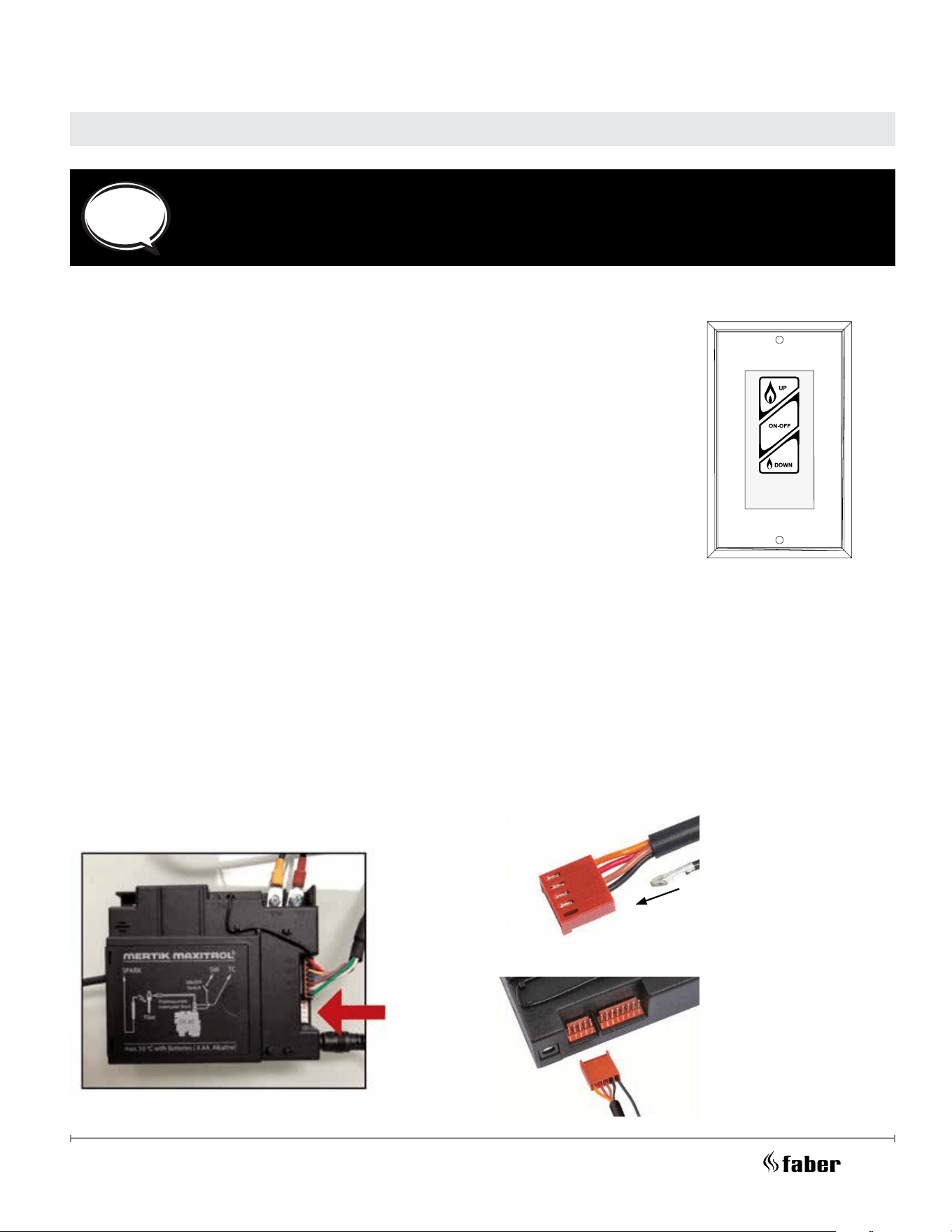
58
The GV60 Wall Switch Accessory Kit can be purchased separately as an option to
control the replace. The accessory kit includes a wall switch, a wall plate, and a
cable available in various lengths.
The following operations can be done from the wall switch:
• Turn the replace on and o.
• Increase and decrease the ame height.
The thermostat and programming functions are not available with the wall switch.
The replace receiver will respond to both the wall switch or remote commands,
regardless of what was used to originally turn the system on.
Combination with Wall Switch
1. Remove the cable plugged in the wall switch harness connection (Image 1) and
replace with cable provided in wall switch accessory kit.
2. Insert the MOLEX crimp terminal of the second thermocouple cable
(G60-ZCTCR...) into the open connector hole of the plug (see image 2). Listen for
a ‟click”.
3. Insert the insulated receptacle into the insulated 2nd thermocouple terminal.
4. Insert the plug connector into the receiver (see image 3).
Wall Switch - Optional
Image 2: Lock MOLEX crimp
terminal of the G60-ZCTCR...
cable inside connector hole of
the plug.
Image 3: Insert plug connector
into the receiver.
If you wish to install the wall switch option, you will need to purchase the GV60 Wall
Switch Accessory Kit, as well as the 2nd thermocouple cable (G60-ZCTCR...) from your
authorized gas replace dealer.
Image 1: Location of wall switch harness
connection indicated by arrow
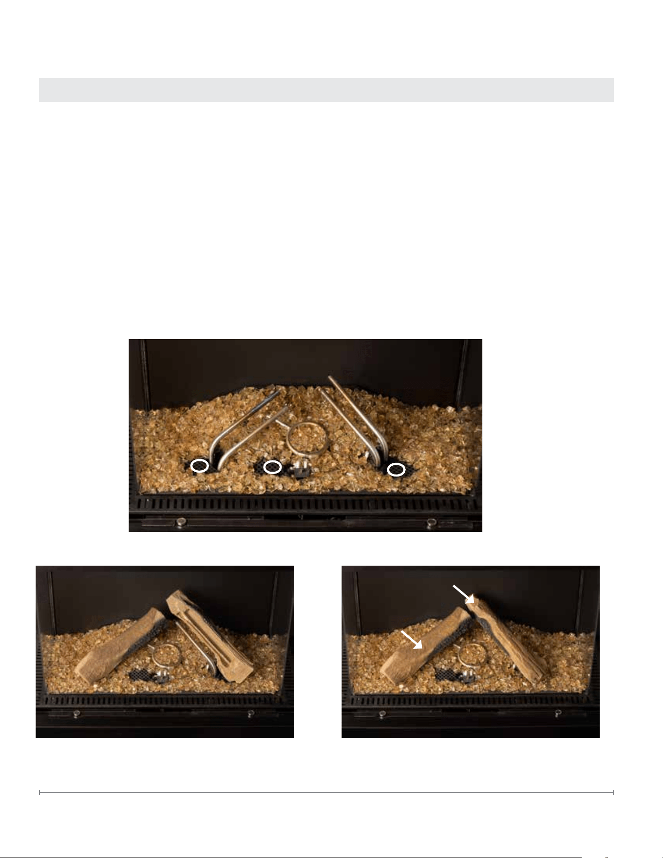
59
FaberFires.com
Media Arrangement
Faber Fireplaces has one of the most realistic log burners in the industry. Follow the instructions below for
information on how to add and arrange media in your replace:
• Do not place any type of media on the pilot or in front of the pilot. Keep 1" (25 mm) distance from the pilot to
allow correct operation of the pilot.
• Logs are specically designed to t over many of the burners. Please ensure that the logs t properly for best
operation.
• Keep the pilot front cover view open to be able to view the pilot spark and ame from outside.
• Use only re glass and ceramic chips provided with unit. All other materials will void warranty.
• When the replace glass is removed and media is placed, ensure the re glass does not fall on the glass lower
frame as that may cause breakage when putting back the front glass.
• Make sure pilot is clear of any re glass pieces.
• Maintain minimum distance of ¼" (6 mm) from media to the replace glass panels.
• Refer to this manual for instructions on how to remove, replace, and arrange the replace logs and glass media.
1. Arrange re glass in the above conguration. Ensure that glass is not
placed in circled areas.
2. Install the two burner logs over the burners as shown above. Once
placed, ensure the logs do not move.
Final Installation
FMG3326F, FMG3726L, FMG3726R, FMG4126B
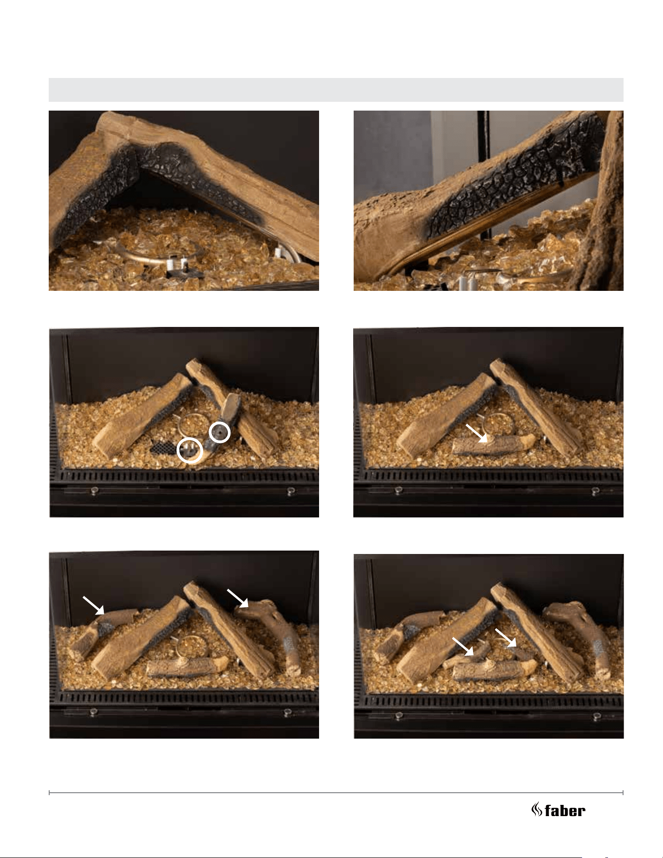
60
Closeup of proper installation position of the front two burner logs over the burners.
3. Install front log in the slot and pilot bracket front pin, as shown above.
4. Position two back side logs as shown above. 5. Position the two front small logs as shown.
Media Arrangement
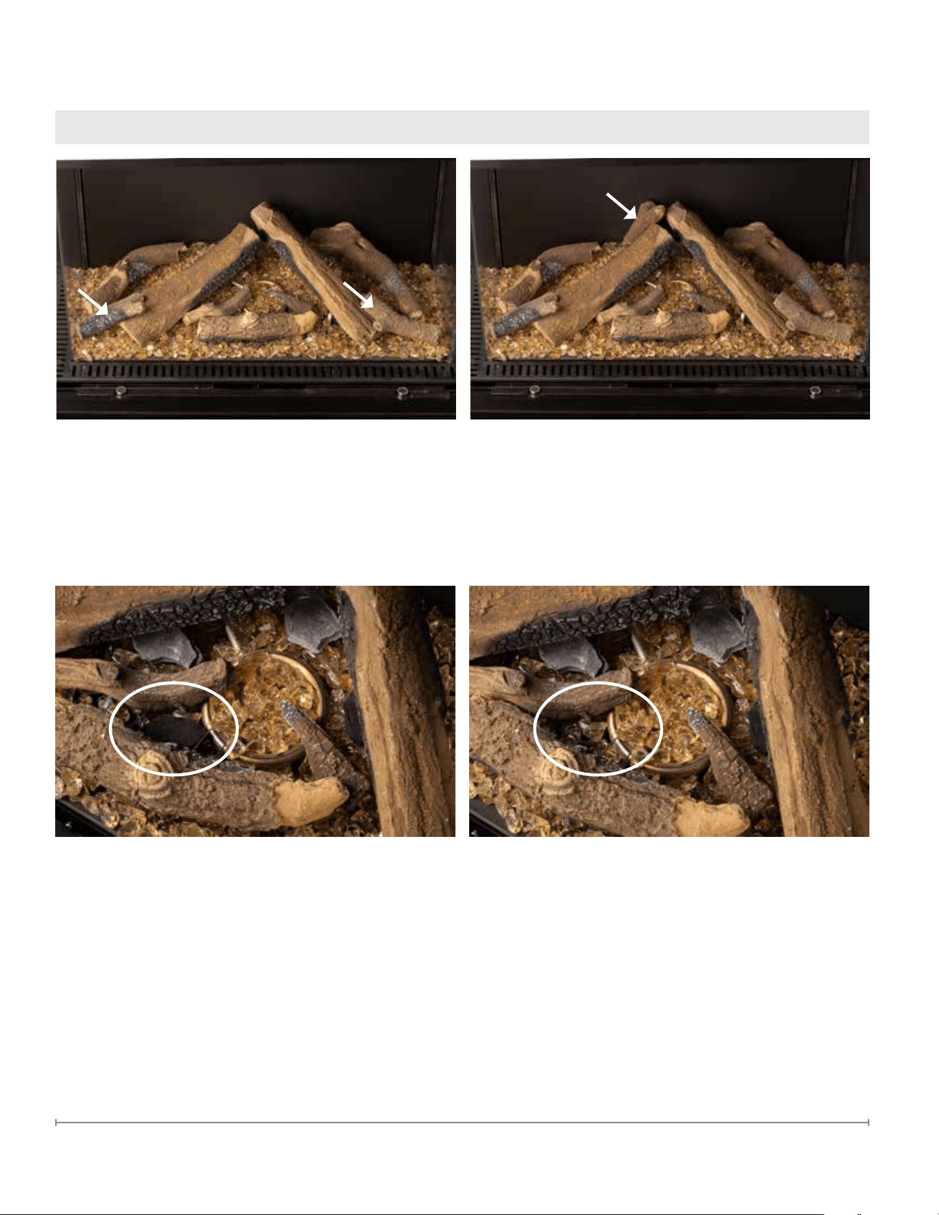
61
FaberFires.com
Final Installation
6. Position the two front side logs. 7. Position the back center log.
Correct media placement versus incorrect placement of media around pilot assembly.
Correct Incorrect
Media Arrangement
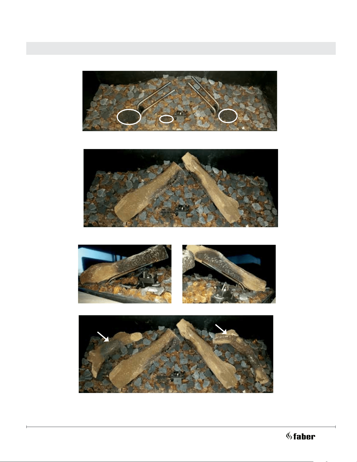
62
Media Arrangement
Final Installation
FMG4326F, FMG4726L, FMG4726R, FMG5126B
1. Arrange re glass in the above conguration. Ensure that glass is not placed in
circled areas.
2. Install the two burner logs over the burners as shown above. Once placed,
ensure the logs do not move.
Closeup of proper installation position of the front two burner logs over the burners.
3. Position two back side logs as shown above.
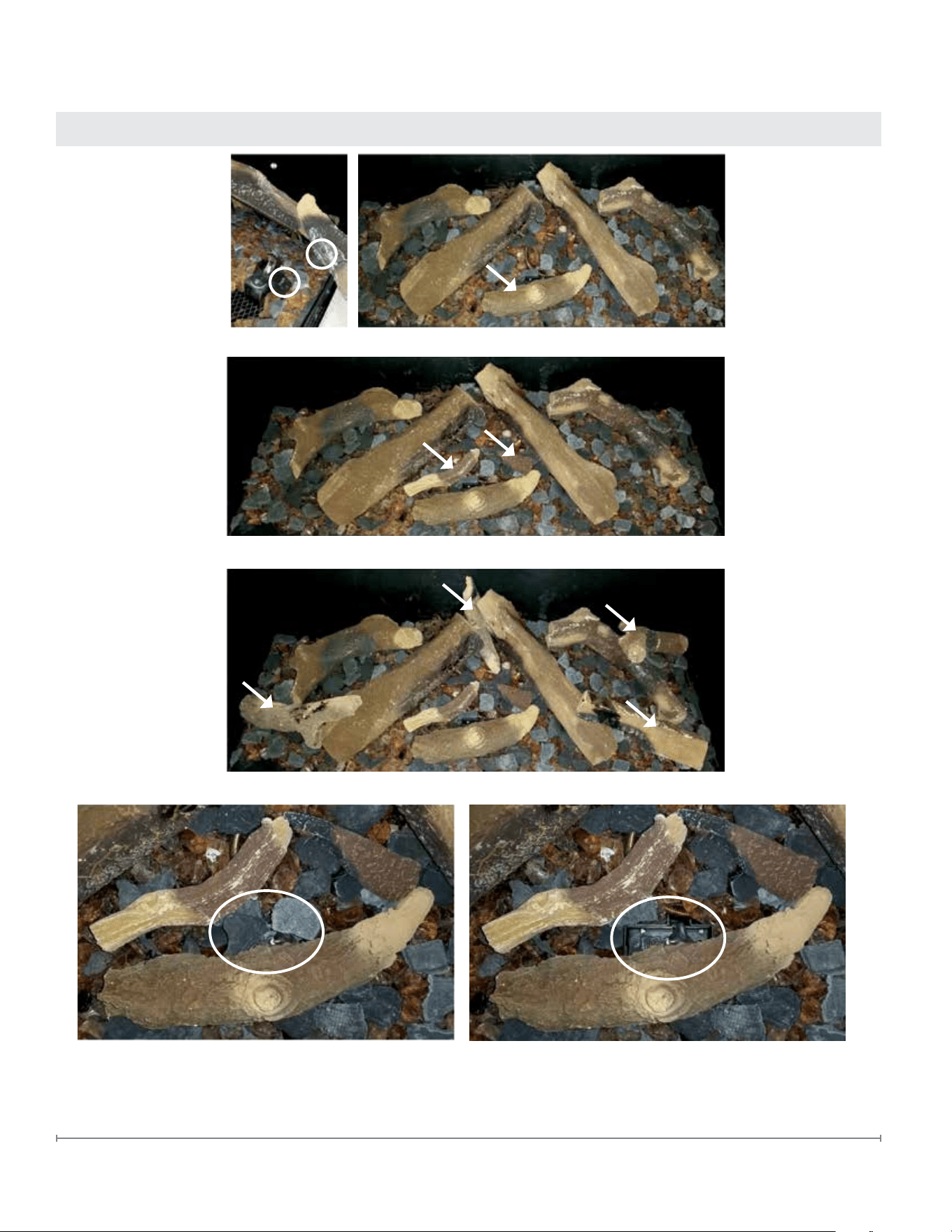
63
FaberFires.com
Media Arrangement
4. Install front log in the slot and pilot bracket front pin, as shown above.
5. Position the two front small logs as shown.
5. Place the remaining logs as shown above.
Correct Incorrect
Correct media placement versus incorrect placement of media around pilot assembly.
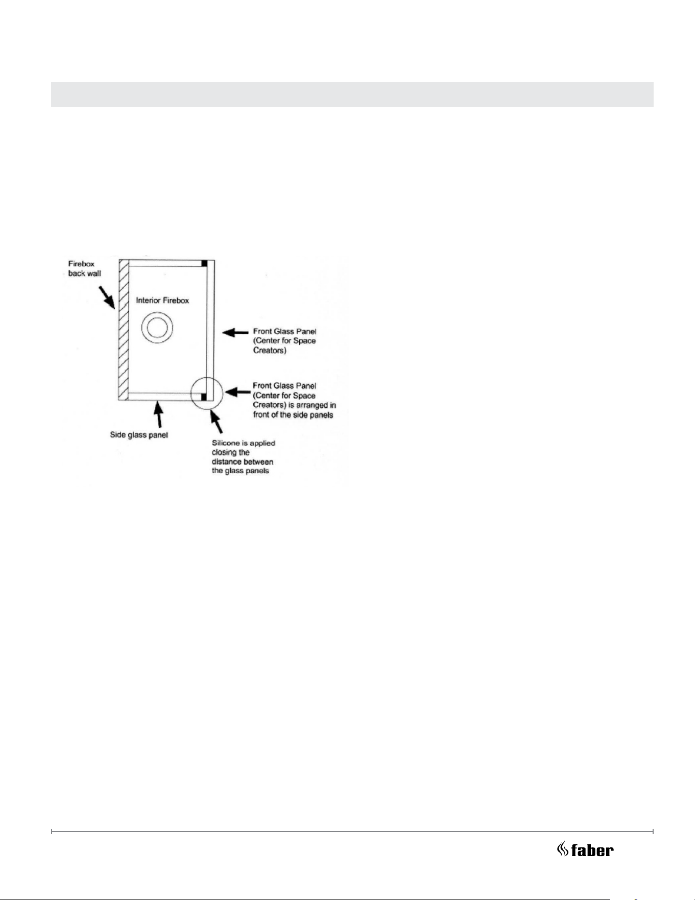
64
Sealing the glass
5 mm ceramic glass front and side panels are provided. Contact Faber for replacement parts if required.
Silicone comes included with replace for application to any glass-to-glass connections on both sides of the glass.
Keep the following guidelines in mind when handling silicone and glass panels:
The purpose of the silicone is to create a gasket, not to ‟glue″ the glass panels together. When placing glass
panels, ensure that the glass is fully in place and that the silicone is lling the space between the glass panels.
Place the front {or center) panel in place rst and then slide the side panel into place so that the silicone edge
touches the glass edge.
Glass Seal Assembly Diagram
• Re-apply silicone only if the original silicone
is damaged (Rutland 500° Clear Silicone is
recommended).
• If new silicone is applied, cure time is 24 hours
before operation of the replace.
• Do not use silicone to seal the glass after it is in
place.
• Always use appropriate materials and cleaning
agents to clean glass. Ammonia free glass
cleaners and/or ceramic glass cleaners are
recommended.
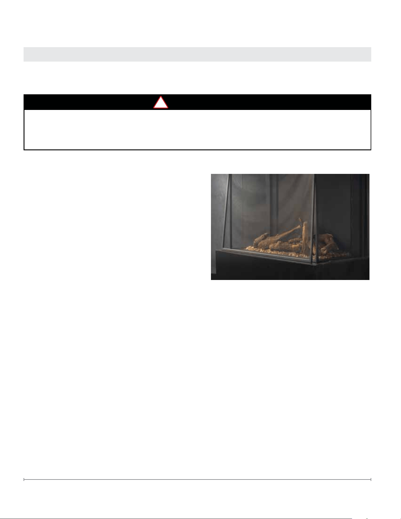
65
FaberFires.com
Follow the instructions below for safety screen removal.
!
NOTE: Safety screen may be shipped separately from the appliance
1. Loosen the coupling nuts from the screen brackets at
the top using a small wrench or socket set.
There are two coupling nuts per bracket. The front
screen has two brackets, and each side screen has
one.
2. Push the top frame of the screen up until it clears the
bottom of the opening.
3. Tilt the bottom of the screen out and pull down so the
top frame clears the opening.
To reinstall the safety screen, follow the steps above in
reverse order. Ensure nuts are secured tightly.
Safety Screen Removal
The barrier is designed to reduce the risk of burns from the hot viewing glass and is provided with this appliance.
It must remain installed for the protection of children and other at-risk individuals.
Do NOT operate the replace without the safety screen barrier.
Feature Removal
!
WARNING
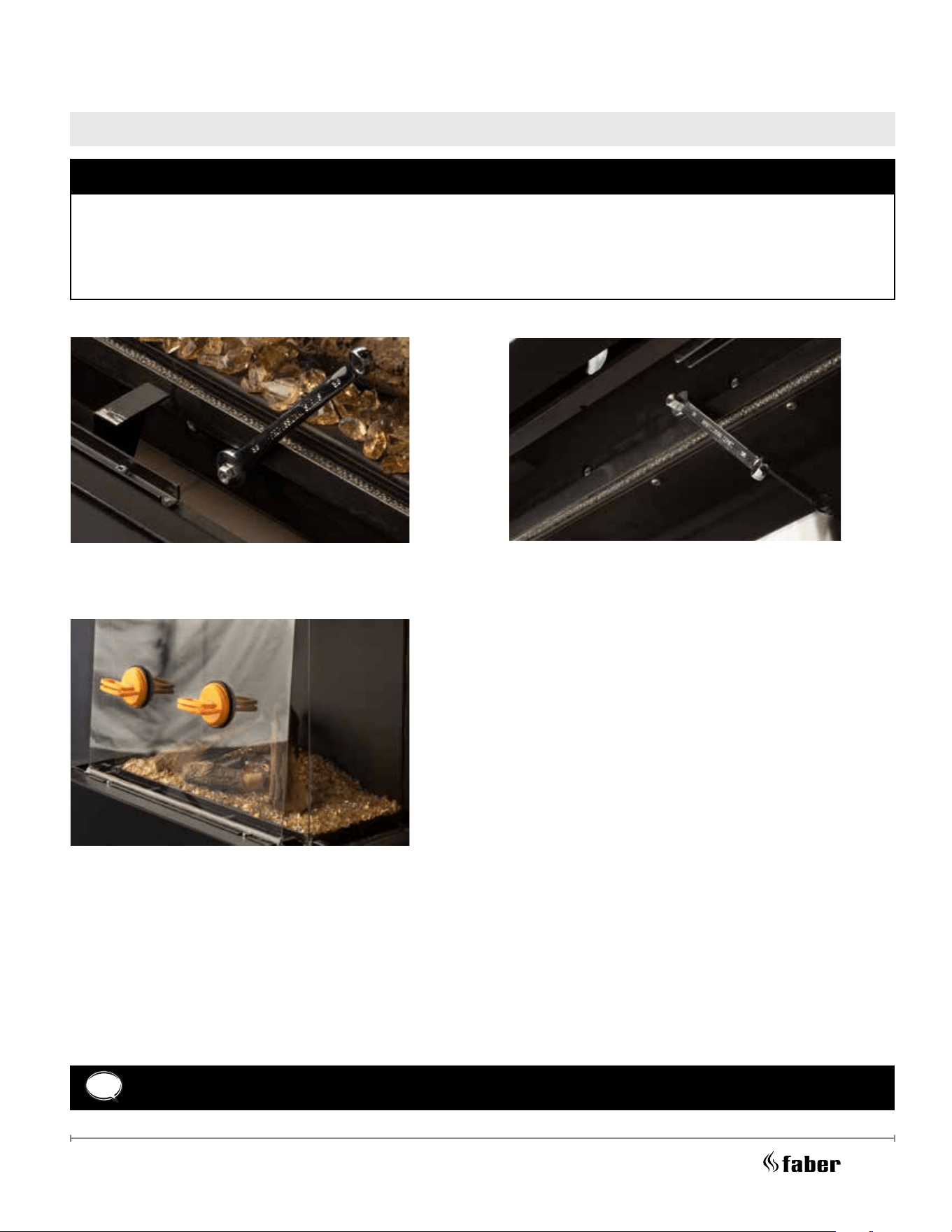
66
!
NOTE: Two suction cups are needed to remove the glass. These are supplied with the replace.
Glass Removal
SAFETY PRECAUTIONS
WARNING: Turn o the replace and allow time for the unit to cool before attempting to remove the glass.
CAUTION: The ceramic glass is very fragile and should be handled with care.
WARNING: Do not operate the appliance with glass removed, cracked or broken. Replacement of the panel(s)
should be done by a licensed or qualied service person.
1. Loosen the coupling nuts on the bottom front
glass bracket using a small wrench or socket
set. Do not completely remove.
2. Remove coupling nuts from top front glass
bracket using a small wrench or socket set.
Remove all coupling nuts leaving the middle
one until last.
3. Carefully taking a sharp blade and cut silicone sealant front edges on exposed glass edges.
4. Attach glass suction cups to the glass. Remove the last coupling nut and hold glass with suction cup and
remove top bracket completely from trim. Using two suction cups, gently raise glass up and remove bottom of
glass from bottom bracket. Slowly swing glass out from bottom and remove glass.
5. Place glass panel in a safe place, being careful not to chip glass edges that are very fragile.
If side glass needs to be removed, repeat steps 1 to 5 for the side glass as well.
!
NOTE: When removing the side glass, the back brackets will also need to be loosened with a small wrench or
socket set before the glass can be removed.
CAUTION: When putting the glass back, DO NOT overtighten the bolts or glass may break.
67
FaberFires.com
1 Suction Cup (1) 9600820100RP
2 Silicone in Small Tube 0800310000RP
3 Matrix Log Set 0443080100RP
4 Glass Beads, orange 10-20mm, 2 kg 1400160100RP
5 Remote Control (918 Mhz Symax, 10-Button Blk) 3002230100RP
6 120V Power Adaptor 2100310100RP
7 LED Glass Cover 5904020100RP
8 SIT Natural Gas Pilot/Ignition Module with Thermocouple 1800020100RP
9 Burner 1 0500200100RP
10 Burner 2 0500210100RP
11 Burner Halo 0500220100RP
12 Burner 3 0500230100RP
13 Burner 4 0500240100RP
14 Receiver 918 MHz, Symax 3002250100RP
15 Combo Control with Receiver 5400320100RP
16 Interrupter, Thermocouple 2800300100RP
17 Thermocouple, Second Burner 3300020100RP
18 Solenoid 3/8" NPT, Latching GV60 1900030100RP
19 Symbio LED Module with LCD wire 3500090100RP
20 Cable, Ignition 25kV 4mm 1200mm 2500990100RP
21 Cable 8-Wire 500mm 2501010100RP
22 Cable, Interrupter-Receiver TC 2501020100RP
23 Cable, Interrupter-Receiver SW 2501020200RP
24 Cable with Molex, TC 2501030100RP
25 Cable, TC 2501030200RP
26 Coupling Nuts for Glass (set of 4) 8100370100RP
27
Front Glass (with Gasket)
FMG3326F 5903370100RP
28 FMG3726L/FMG3726R 5903370200RP
29 FMG4126B 5903370400RP
30 FMG4326F 5903370500RP
31
FMG4726L/FMG4726R
5903370600RP
FMG5126B
32 Side Glass (with Gasket)
FMG3726L/FMG3726R
5903370300RP
FMG4126B
FMG4726L/FMG4726R
FMG5126B
33
Front Screen
FMG3326F 0442980300RP
34 FMG3726L/FMG3726R 0442980400RP
35 FMG4126B 0442980100RP
36 FMG4326F 0442980600RP
37 FMG4726L/FMG4726R 0442980700RP
38 FMG5126B 0442980500RP
38 Side Screen
FMG3726L/FMG3726R
0442980200RP
FMG4126B
FMG4726L/FMG4726R
FMG5126B
Replacement Parts
68
• It is recommended that a qualied service technician perform a routine inspection at the beginning of each
heating season.
• Disconnect power before attempting maintenance or repair of the replace.
• Installation and maintenance must be performed by an authorized qualied installer, service agency, or gas
supplier.
• Any safety screen or guard removed for servicing must be placed back before operating this appliance.
• DO NOT USE this appliance if any part has been under water. Immediately call a qualied service technician to
inspect the unit and to replace any part of the control system and any gas valve that has been under water or
impacted.
• Any alteration to the product that causes soot or carbon to accumulate and results in damage is not the
responsibility of the manufacturer.
• Do not modify or substitute any part of this appliance.
• Inspect the external vent cap on a regular basis to make sure that no debris, plants, trees, or shrubs are
interfering with the airow.
• Do not operate the replace without the replace glass.
• It is imperative that control compartments, screens, or fans system for double glass are kept clean and free of
obstructions.
These areas provide the air necessary for safe operation.
• Light the heater using the built-in igniter. Do not use matches or any other external device to light the replace.
• Never remove, replace, modify or substitute any part of the heater unless instructions are given in this manual.
AII other work must be done by a trained technician. Do not modify or replace orices.
Maintenance Instructions
1. Always turn o the gas valve before cleaning. For relighting, refer to lighting instructions. Keep the burner and
control compartment clean by brushing and vacuuming at least once a year. When cleaning the logs, use a soft
clean paint brush as the logs are fragile and easily damaged.
2. Clean appliance and door with a damp cloth (never when unit is hot). Never use an abrasive cleaner. The glass
should be cleaned with a gas replace glass cleaner. The glass should be cleaned when it starts looking cloudy.
3. The replace is nished in a heat-resistant paint and should only be renished with heat-resistant paint. Faber
part number.
4. Make a periodic check of burner for proper position and condition. Visually check the ame of the burner
periodically, making sure the ames are steady; not lifting or oating. If there is a problem, call a qualied
service person.
5. The appliance and venting system must be inspected before use, and at least annually, by qualied eld service
person, to ensure that the ow of combustion and ventilation air is not obstructed.
!
NOTE: Never operate the appliance without the glass properly secured in place.
6. In the event this appliance has been serviced check that the vent-air system has been properly resealed &
reinstalled in accordance with the manufacturer’s instructions.
7. Verify operation after servicing.
Maintenance
!
WARNING

69
FaberFires.com
Maintenance
Yearly Service
Failure to inspect and maintain the replace may lead to improper combustion and a potentially dangerous situation.
We recommend the following procedures be done by a qualied technician.
Glass Maintenance
• Always use suction cups to remove the replace glass. Use the manual procedure for instruction on how to
remove the replace glass.
• Always use gloves when removing the glass to protect your hand and prevent nger prints on the glass.
• DO NOT USE abrasive cleaners on the glass panels. DO NOT ATTEMPT to clean the glass panels when they
are hot.
• Do not use normal household (usually ammonia-based) glass cleaners to clean the glass as these cleaners can
leave a permanent stain. Only a gas replace glass cleaner should be used.
• Verify no cracks or breakage in the glass.
• Place glass in a safe location to prevent breakage.
• Never attempt to operate the replace without the replace glass.
Pilot Maintenance
• Visually inspect the pilot ame. The pilot ame should be always present when the replace is in operation.
• Make sure the pilot ame has two ame tips pointing to the ame sensor (thermocouple) and to the center of
the burner.
• Make sure the pilot area is clean from any dust, media or any other debris that may disrupt the operation of the
ignition system. Lint or foreign material must be removed with a brush or vacuum.
• Verify replace ignition using the remote or wall switch. Verify electronic ignition, sparking sequence, pilot
operation and burner ignition.
Burner Maintenance
• The ames from the burner should be visually checked. The ame should have a blue base and yellow tops and
be candle-like in appearance.
• If excessive soot is found inside the rebox area, the replace will require adjustment. Verify the air shutter and
vent restrictor setting and document any changes.
• If the ame becomes sooty, dark orange, or extremely tall, do not operate the heater.
• Measure gas pressure. Inlet ___ W.C., Outlet ___ W.C.
Vent Maintenance
The following venting system inspection by a qualied service technician is recommended every six months:
• Inspect for excessive condensation, e.g., water droplets forming in the inner lining and subsequently dripping
out of the joints. This can cause corrosion in the system.
• Check for corrosion in areas exposed to the elements. Where rust spots or holes have appeared, these must be
immediately replaced.
• Ensure that there is no foreign material in the vents. Survey by removing the cap and shining a light down
the vent.
• Check all joints and pipes to make sure that nothing has been disturbed or loosened.
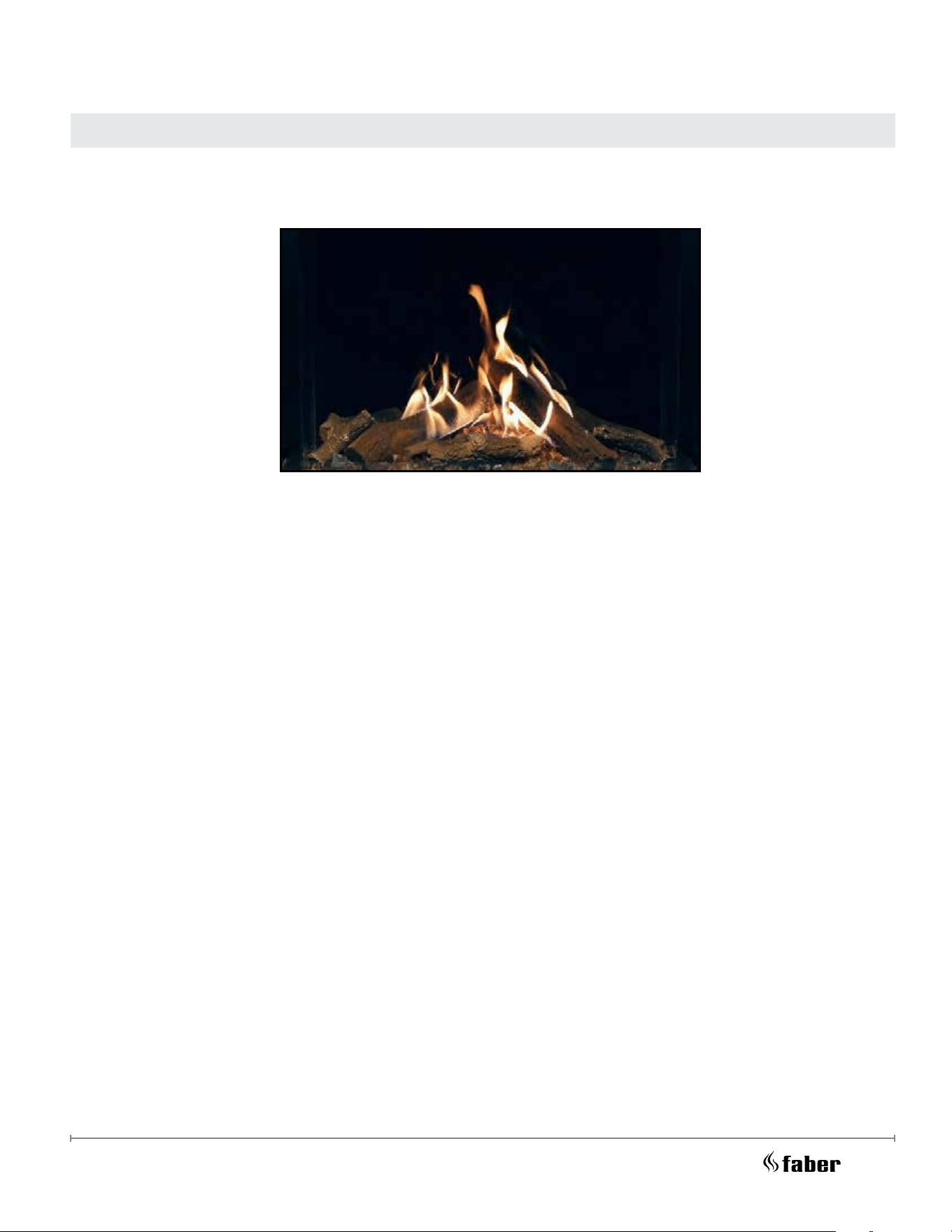
70
Flame Pattern
Periodically check the pilot and main burner ames. Correct pilot ame pattern has two strong blue ames:
1 owing around the ame sensor and 1 owing across the burner (it does not have to be touching the burner).
Incorrect ame pattern will have small, probably yellow ames, not coming into proper contact with the rear burner
or ame sensor.
!
NOTE: If you have an incorrect ame pattern, contact your Faber dealer for further instructions.
Correct main burner ame pattern
71
FaberFires.com
Maintenance
Log Replacement
Glass Gasket
Glass
The unit should never be used with broken logs. Turn o the gas valve and allow the unit to cool before opening
door and carefully remove the logs. (The pilot light generates enough heat to burn someone.) If for any reason a log
should need replacement, you must use the proper replacement log. The position of these logs must be as shown in
the diagrams under Log Installation.
!
NOTE: Improper positioning of logs may create carbon build-up and will severely alter the unit’s
performance which is not covered under warranty.
If the glass gasket on the appliance requires replacement a graphite gasket specically designed for this appliance is
required. This gasket is supplied with preinstalled self-adhesive tape.
There is also gasket installed on the edge of the inner glass to protect against breakage when installing the glass.
Your Faber replace is supplied with safety screen and a 5 mm ceramic inner glass. If your glass requires cleaning,
we recommend using an approved ceramic glass cleaner available at all authorized replace dealers. Do not use
abrasive materials or cleaners.
• Do not clean when the glass is hot.
• The use of substitute glass will void all product warranties.
• Care must be taken to avoid breakage of the glass.
• Do not strike or abuse the glass.
• Do not operate this replace without the glass front, or with a cracked or broken glass front.
• Wear gloves and safety glasses when removing damaged or broken glass.
• Replacement of the glass panels should be done by a licensed or qualied service person.
1. Always turn o the gas valve before cleaning. For relighting, refer to lighting instructions. Keep the burner and
control compartment clean by brushing and vacuuming at least once a year. When cleaning the logs, use a soft
clean paint brush as the logs are fragile and easily damaged.
2. Clean appliance and door with a damp cloth (never when unit is hot). Never use an abrasive cleaner. The glass
should be cleaned with a gas replace glass cleaner. The glass should be cleaned when it starts looking cloudy.
!
WARNING

72
Glass Replacement
In the event that you break your glass by impact, purchase your replacement from an authorized dealer only.
Reinstall as per instructions provided with replacement.
• Check for evidence of excessive condensation, such as water droplets forming in the inner liner, and
subsequently dripping out the joints, continuous condensation can cause corrosion of caps, pipe, and ttings.
It may be caused by having excessive lateral runs, too many elbows, and exterior portions of the system being
exposed to cold weather.
• Inspect joints, to verify that no pipe sections or ttings have been disturbed, and consequently loosened. Also
check mechanical supports such as Wall Straps, or plumbers’ tape for rigidity.
General Vent Maintenance
Conduct an inspection of the venting system twice a year. Recommended areas to inspect as follows:
1. Check the Venting System for corrosion in areas that are exposed to the elements. These will appear as rust
spots or streaks, and in extreme cases, holes. These components should be replaced immediately.
2. Remove the Cap, and shine a ashlight down the Vent. Remove any bird nests, or other foreign material.
3. Check for evidence of excessive condensation, such as water droplets forming in the inner liner, and
subsequently dripping out the joints, continuous condensation can cause corrosion of caps, pipe, and ttings.
It may be caused by having excessive lateral runs, too many elbows, and exterior portions of the system being
exposed to cold weather.
4. Inspect joints, to verify that no pipe sections or ttings have been disturbed, and consequently loosened. Also
check mechanical supports such as Wall Straps, or plumbers’ tape for rigidity.
73
FaberFires.com
Unit does not power on using the remote control
Remote control is not synced
Remote must learn new code
Press and hold the receiver’s reset button until you
hear 2 acoustic signals. After the second longer
acoustic signal, release the reset button and within the
subsequent 20 seconds, press (down arrow) and hold
on the remote handset until you hear an additional long
acoustic signal conrming the new code is set.
• NOTE: if 15-20 seconds pass while pressing and
holding (down arrow) and a long single tone is heard,
conrm the sticker label (see below) on the remote
handset and back of the receiver are both blue, or
remote sticker is black, and the receiver sticker is
green.
Remote batteries are dead Replace batteries (2 × AAA batteries)
Receiver batteries are dead Replace batteries (2 × AA alkaline batteries)
Pins on the 8-pin connector are bent Inspect the pins and straighten as needed
Receiver is surrounded by metal - transmission range
is reduced
Bring remote closer to receiver
RF interference - transmission ranged is reduced Change the position of the antenna
Receiver is defective Replace receiver
Remote is defective
Ensure labels on back of remote and receiver match in
color. Blue and blue, green to black.
Replace remote if needed and reprogram code.
No ignition, no tone
Remote and receiver are not synced
See above to ensure remote has correct code to
receiver.
Receiver has no power Check power to receiver.
Receiver is defective Replace receiver
No Ignition; One continuous 5 second tone (7 short beeps might be heard prior to the 5 second tone)
Loose wire Inspect wires, tighten as necessary
Bent pins on 8 wire connectors Inspect pins, straighten as necessary
Receiver requires power cycling Reset receiver and resync remote
Receiver is defective Replace receiver
Valve is defective Replace valve
Troubleshooting Guide
74
No Pilot Flame and control continues to spark
Air in the pilot line. Purge the line (start ignition several times.)
No spark at pilot burner.
Check spark gap; Check for spark in location along
cable.
Check spark on the receiver by disconnecting the spark
cable from the receiver.
Inappropriate inlet pressure Conrm gas pressure is correct rating for NG/LPG.
Air seal issue around pilot. Inspect and correct as needed.
Clogged pilot gas line.
To test, remove glass and attempt to light pilot with long
stem-lighter.
Disconnect pilot line from valve and check gas ow.
Reset receiver and attempt to re-ignite.
Valve is defective Replace valve
Receiver is defective Replace receiver and reprogram code.
Pilot is lit, and control continues to spark. Valve shuts after 10-30 seconds.
Over tightened thermocouple interrupter Contact customer service or gas technician
Thermocouple is defective Replace thermocouple
Receiver is defective Replace receiver
Pilot is lit and sparking stops. Valve shuts after 3-60 seconds. Valve does not operate manually.
Not enough voltage generated from the thermocouple
or too much resistance in the circuit.
Use a digital multimeter set in the mV range and
measure the voltage by connecting the test leads to
the spade connector. Spade connector is located on
the outer surface, directly beside the magnet nut.
The available voltage must be at least 5 mV. The
manufacturer must specify the drop time for the
application. The drop time can be measured after the
thermocouple is heated.
Low inlet pressure.
Conrm regulator pressure and sizing. Replace if
necessary.
Thermocouple is defective Replace thermocouple
Valve is defective Replace valve
3 short beeps while the motor turns
Receiver batteries are low Replace batteries (2 × AA alkaline batteries)
Pilot ame lights but there is no main gas ow
Low inlet pressure Contact customer service or gas technician
Valve turned down to pilot ow.
Turn ame to high re by pressing up button on remote
handset.
Main gas burner line is crimped Contact customer service or gas technician
Clogged burner orice Contact customer service or gas technician
Valve is defective Replace valve
75
FaberFires.com
Limited Lifetime Warranty
Faber extends this Limited Lifetime Warranty to the original purchaser of this appliance provided the product
remains in the original place of installation. The items covered by this limited warranty and the period of such
coverage is set forth in the table below. Some conditions apply (see below).
The policy is not transferable, amendable, or negotiable under any circumstances.
Part
Parts & Labor Warranty Coverage
Lifetime 5 years 1 year
Firebox
×
Steel Burner Tube
×
Glass Thermal breakage only
×
All Surrounds/Inlays Finishes
×
Panels and Log sets
×
Valve assembly and all gas control components, (Pilot assembly,
Spark Electrode, Pilot Tubing, Orices, Thermocouple)
×
All Other Electrical components (Ignition Control Boards, Wiring,
Switches, Battery Pack, Remote Control Systems)
×
Glass Panels
×
Venting/Venting Components
×
All Stainless Steel Surrounds
×
All Firebox Media
×
All hardware
×
Mesh/Glass Safety Barriers
×
Glass (Crazing)
×
Warranty

76
Conditions:
Warranty protects against defects in manufacture or
Faber factory assembled components only unless herein
specied otherwise.
Any part(s) found to be defective during the warranty
period as outlined above will be repaired or replaced at
Faber’s option through an accredited distributor, dealer
or preapproved and assigned agent provided that the
defective part is returned to the distributor, dealer or
agent for inspection if requested by Faber. Alternatively,
Faber may at its own discretion fully discharge all of its
obligations under the warranty by refunding the veried
purchase price of the product to the original purchaser.
The purchase price must be conrmed by the original
Bill of Sale.
The authorized selling dealer, or an alternative
authorized Faber dealer if preapproved by Faber, is
responsible for all ineld diagnosis and service work
related to all warranty claims. Faber is not responsible
for results or costs of workmanship of unauthorized
Faber dealers or agents in the negligence of their
service work.
At all times Faber reserves the right to inspect reported
complaints on location in the eld claimed to be
defective prior to processing or authorizing of any claim.
Failure to allow this upon request will void the warranty.
All warranty claims must be submitted by the dealer
servicing the claim, including a copy of the Bill of Sale
(proof of purchase by you).
All claims must be complete and provide full details
as requested by Faber to receive consideration for
evaluation. Incomplete claims may be rejected. Unit
must be installed according to all manufacturers’
instructions as per the manual.
All Local and National required codes must be met. The
installer is responsible to ensure the unit is operating as
designed at the time of installation.
The original purchaser is responsible for annual
maintenance of the unit, as outlined in the owner’s
manual. As outlined below, the warranty may be voided
due to problems caused by lack of maintenance.
Repair/replacement parts purchased by the consumer
from Faber after the original coverage has expired on
the unit will carry a 90-day warranty, valid with a receipt
only. Any item shown to be defective will be repaired or
replaced at our discretion. No labor coverage is included
with these parts.
Exclusions:
This Limited Lifetime Warranty does not extend to
paint, rust or corrosion of any kind due to a lack of
maintenance or improper venting, combustion air
provision, corrosive chemicals (i.e. chlorine, salt, air,
etc.), door or glass gasketing.
Malfunction, damage or performance-based issues
as a result of environmental conditions, location,
chemical damages, downdrafts, installation error,
installation by an unqualied installer, incorrect chimney
components (including but not limited to cap size or
type), operator error, abuse, misuse, use of improper
fuels, lack of regular maintenance and upkeep, acts
of God, weather-related problems from hurricanes,
tornadoes, earthquakes, oods, lightning strikes/bolts
or acts of terrorism or war, which result in malfunction
of the appliance are not covered under the terms of this
Limited Lifetime Warranty.
Faber has no obligation to enhance or modify any
unit once manufactured (i.e. as products evolve, eld
modications or upgrades will not be performed on
existing appliances).
This warranty does not cover dealer travel costs for
diagnostic or service work. All labor rates paid to
authorized dealers are subsidized, predetermined rates.
Dealers may charge homeowner for travel and additional
time beyond their subsidy.
Any unit showing signs of neglect or misuse will not be
covered under the terms of this warranty policy and
may void this warranty. This includes units with rusted
or corroded reboxes which have not been reported
as rusted or corroded within three (3) months of
installation/purchase.
Units which show evidence of being operated while
damaged, or with problems known to the purchaser and
causing further damages will void this warranty.
Units where the serial no. has been altered, deleted,
removed or made illegible will void this warranty.
Minor movement, expansion and contraction of the steel
is normal and is not covered under the terms of this
warranty.
Faber is not liable for the removal or replacement of
facings or nishing in order to repair or replace any
appliance in the eld.
Freight damages for products or parts are not covered
under the terms of the warranty.
Products made or provided by other manufacturers and
used in conjunction with the Faber appliance without
prior authorization from Fabermay void this warranty.

77
FaberFires.com
Limitations of Liability:
The original purchaser’s exclusive remedy under this
warranty, and Faber’s sole obligation under this warranty,
express or implied, in contract or in tort, shall be limited
to replacement, repair, or refund, as outlined above.
IN NO EVENT WILL Faber BE LIABLE UNDER THIS
WARRANTY FOR ANY INCIDENTAL OR CONSEQUENTIAL
COMMERCIAL DAMAGES OR DAMAGES TO PROPERTY.
TO THE EXTENT PERMITTED BY APPLICABLE LAW,
Faber MAKES NO EXPRESS WARRANTIES OTHER THAN
THE WARRANTY SPECIFIED HEREIN. THE DURATION
OF ANY IMPLIED WARRANTY IS LIMITED TO DURATION
OF THE EXPRESSED WARRANTY SPECIFIED ABOVE. IF
IMPLIED WARRANTIES CANNOT BE DISCLAIMED, THEN
SUCH WARRANTIES ARE LIMITED IN DURATION TO THE
DURATION OF THIS WARRANTY.
Some U.S. states do not allow limitations on how long
an implied warranty lasts, or allow exclusion or limitation
of incidental or consequential damages, so the above
limitations or exclusions may not apply to you.
Customers located outside the U.S. should consult their
local, provincial or national legal codes for additional
terms which may be applicable to this warranty.
How to Obtain Warranty Service:
Customers should contact the authorized selling dealer
to obtain warranty service. In the event the authorized
selling dealer is unable to provide warranty service,
please contact Faber by mail at the address listed below.
Please include a brief description of the problem and
your address, email and telephone contact information. A
representative will contact you to make arrangements for
an inspection and/or warranty service.
North American Warrantor:
Glen Dimplex Americas
1367 Industrial Rd.
Cambridge (Ontario)
N3H 4W3, ON Canada
1-888-346-7539
Product Registration and Customer Support:
Thank you for choosing a Faber Fireplace. To provide
the best support for your product, we request that you
complete a product registration form within ninety (90)
days of purchase.
Warranty

®
Social icon
Circle
Only use blue and/or white.
For more details check out our
Brand Guidelines.
Social icon
Circle
Only use blue and/or white.
For more details check out our
Brand Guidelines.
Social icon
Circle
Only use blue and/or white.
For more details check out our
Brand Guidelines.
BRANDS OF GLEN DIMPLEX AMERICAS