This manual must only be used by
a qualified heating installer / service
technician. Read all instructions,
including this manual and the Crest
Service Manual, before installing.
Perform steps in the order given.
Failure to comply could result in
severe personal injury, death, or
substantial property damage.
⚠WARNING
Save this manual for future reference.
100208043_2000004587_Rev BA
Installation & Operation Manual
Models: 751 - 6001
Series: 100 - 101 & 110 - 111

2
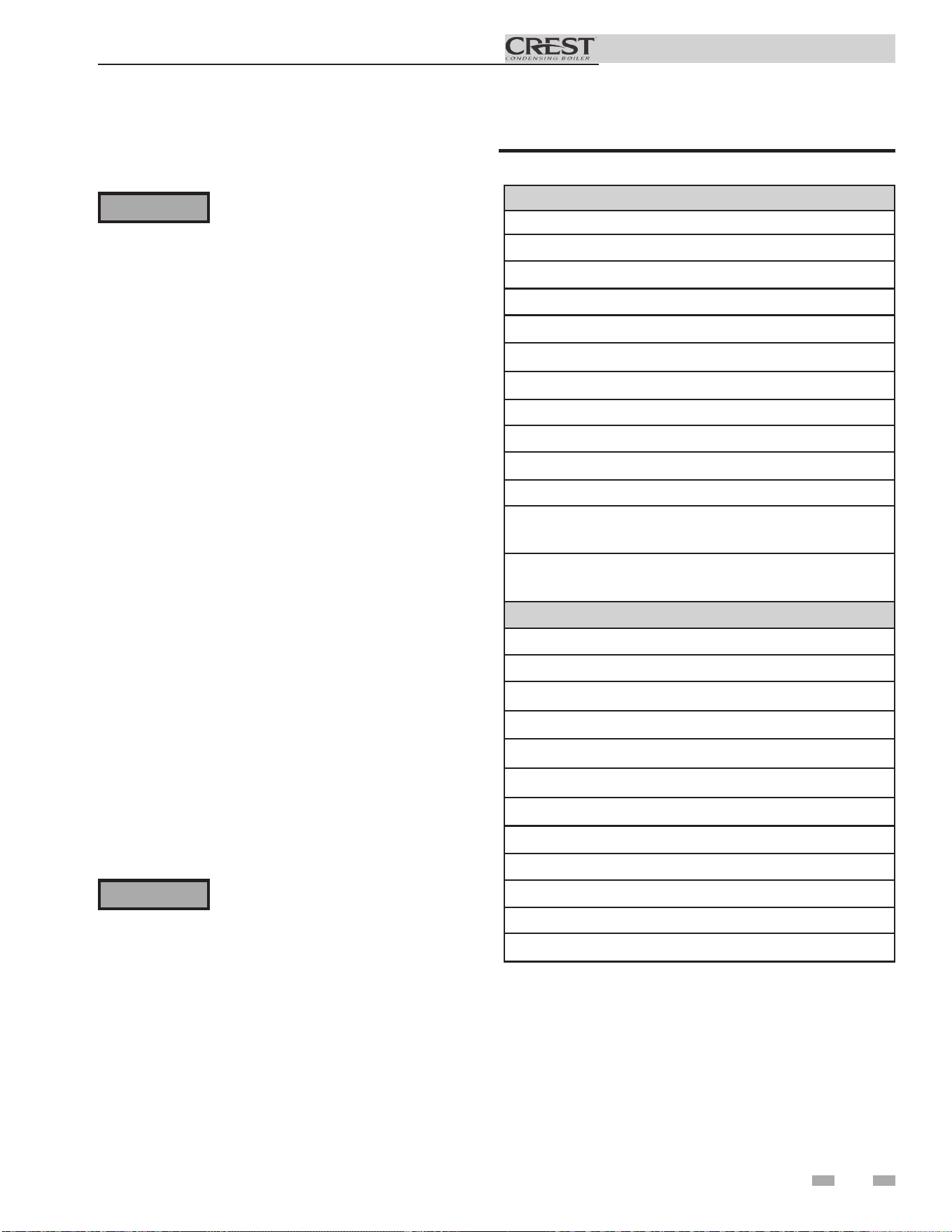
Contents
Hazard definitions
The following defined terms are used throughout this manual to bring attention to the presence of hazards of various risk levels or
to important information concerning the life of the product.
⚠ DANGER
⚠WARNING
⚠CAUTION
CAUTION
NOTICE
DANGER indicates an imminently hazardous situation which, if not avoided, will result in death or serious
injury.
WARNING indicates a potentially hazardous situation which, if not avoided, could result in death or serious
injury.
CAUTION indicates a potentially hazardous situation which, if not avoided, may result in minor or moderate
injury.
CAUTION used without the safety alert symbol indicates a potentially hazardous situation which, if not
avoided, may result in property damage.
NOTICE indicates special instructions on installation, operation, or maintenance that are important but not
related to personal injury or property damage.
HAZARD DEFINITIONS .................................................. 2
PLEASE READ BEFORE PROCEEDING ..................... 3
THE CREST -- HOW IT WORKS ................................. 4-5
RATINGS .......................................................................... 6
1. DETERMINE BOILER LOCATION
Clearances ......................................................................... 7
Provide Air Openings to Room .......................................... 8
Flooring and Foundation ................................................... 8
Vent and Air Piping ............................................................ 8
Prevent Combustion Air Contamination ............................. 8
Using an Existing Vent System to Install a New Boiler ..... 9
Corrosive Contaminants and Sources ............................... 9
Removing a Boiler from Existing Common Vent .............. 10
Remove Boiler from Wood Pallet ..................................... 11
Combustion and Ventilation Air Requirements ........... 12-13
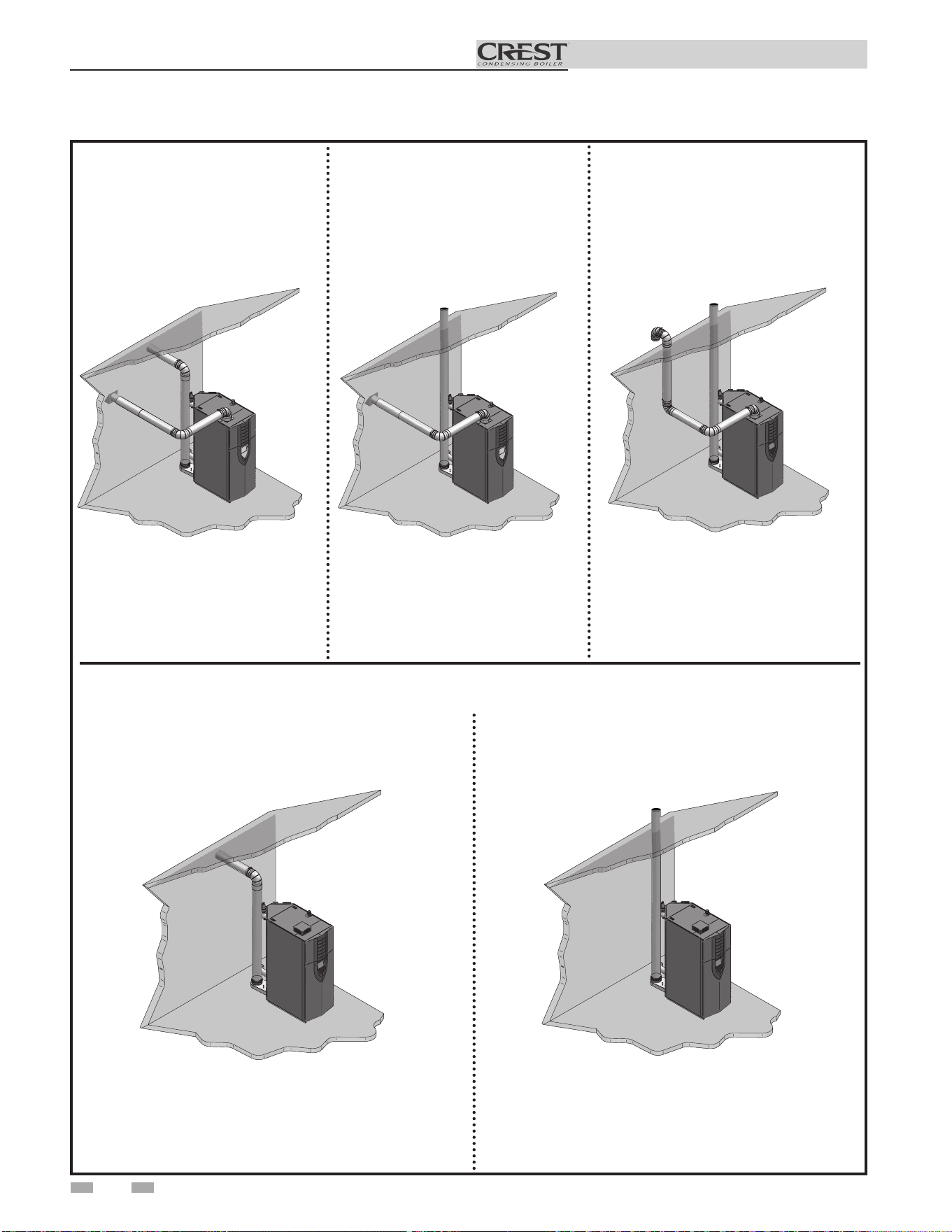
2. GENERAL VENTING
Direct Venting Options - Sidewall Vent ............................ 14
Direct Venting Options - Vertical Vent .............................. 14
Direct Venting Options - Vert. Vent, Opt. Rm Air ............. 14
Direct Venting Options - Vert. Vent, Sidewall Air ............. 14
Install Vent and Combustion Air Piping ........................... 15
Air Inlet Pipe Materials ................................................ 15
Vent and Air Piping .......................................................... 16
Air Intake / Vent Connections .......................................... 16
Min./Max. Combustion Air & Vent Piping Lengths ........... 18
Vent and Air Piping .......................................................... 19
Common Venting ............................................................. 20
PVC/CPVC .................................................................. 20-21
Polypropylene ................................................................... 22
3. VERTICAL DIRECT VENTING
Vent/Air Termination - Vertical ......................................... 23
Determine Location ..................................................... 23
Prepare Roof Penetrations ......................................... 23
Termination and Fittings ........................................ 23-24
Multiple Vent/Air Terminations .................................... 24
4. SIDEWALL DIRECT VENTING
Vent/Air Termination - Sidewall ................................... 25-27
Determine Location ................................................ 25-27
Prepare Wall Penetrations .......................................... 27
Termination and Fittings ............................................. 27
Multiple Vent/Air Terminations ............................... 27-28
Room Air ..................................................................... 28
5. HYDRONIC PIPING
System Water Piping Methods ......................................... 29
Low Water Cutoff Device ................................................. 29
Chilled Water System ....................................................... 29
Freeze Protection ............................................................. 29
General Piping Information .............................................. 29
Circulator Sizing ............................................................... 30
Near Boiler Piping Components ....................................... 32
6. GAS CONNECTIONS
Connecting Gas Supply Piping ........................................ 37
Natural Gas ...................................................................... 38
Pipe Sizing for Natural Gas ........................................ 38
Natural Gas Supply Pressure Requirements ............. 38
Propane Gas .................................................................... 38
Pipe Sizing for Propane Gas ...................................... 38
Propane Supply Pressure Requirements ................... 38
Check Inlet Gas Supply .............................................. 39-40
Gas Valve Replacement .................................................. 40
7. FIELD WIRING
Line Voltage Connections ................................................ 41
Low Voltage Connections ................................................ 42
Wiring of the Cascade ...................................................... 43
8. CONDENSATE DISPOSAL
Condensate Drain ............................................................ 45
9. STARTUP ............................................................... 46-54
10. OPERATING INFORMATION
General ........................................................................ 55-57
Cascade ........................................................................... 58
Sequence of Operation .................................................... 59
Home Screen ................................................................... 60
11. MAINTENANCE
Maintenance & Annual Startup .............................. 61-65
12. DIAGRAMS
Ladder Diagrams ................................. 66,68,70, and 72
Wiring Diagrams .................................. 67,69,71, and 73
Revision Notes .................................................. Back Cover
Installation & Operation Manual
Please read before proceeding
Installer – Read all instructions, including
this manual and the Crest Service Manual,
before installing. Perform steps in the
order given.
User – This manual is for use only
by a qualified heating installer/
service technician. Refer to the User’s
Information Manual for your reference.
Have this boiler serviced/inspected by
a qualified service technician, at least
annually.
Failure to comply with the above could
result in severe personal injury, death or
substantial property damage.
Failure to adhere to the guidelines on this
page can result in severe personal injury,
death, or substantial property damage.
When servicing boiler –
• To avoid electric shock, disconnect electrical supply
before performing maintenance.
• To avoid severe burns, allow boiler to cool before
performing maintenance.
Boiler operation –
• Do not block flow of combustion or ventilation air to
the boiler.
• Should overheating occur or gas supply fail to shut off,
do not turn off or disconnect electrical supply to
circulator. Instead, shut off the gas supply at a location
external to the appliance.
• Do not use this boiler if any part has been under water.
The possible damage to a flooded appliance can be
extensive and present numerous safety hazards. Any
appliance that has been under water must be replaced.
• The installer must verify that at least one carbon
monoxide alarm has been installed within a residential
living space or home following the alarm manufacturer’s
instructions and applicable local codes before putting the
appliance into operation.
Boiler water –
• Thoroughly flush the system to remove debris. Use
an approved pre-commissioning cleaner (see Start-Up
Section), without the boiler connected, to clean the
system and remove sediment. The high-efficiency heat
exchanger can be damaged by build-up or corrosion due
to sediment.
NOTE: Cleaners are designed for either new systems or
pre-existing systems. Choose accordingly.
Freeze protection fluids –
• Lochinvar recommends inhibited propylene glycol
solutions which are specifically formulated for hydronic
systems. Never use automotive antifreeze.
When calling or writing about the boiler
– Please have the boiler model and serial
number from the boiler rating plate.
Consider piping and installation when
determining boiler location.
Any claims for damage or shortage in
shipment must be filed immediately
against the transportation company by
the consignee.
Factory warranty (shipped with unit) does
not apply to units improperly installed or
improperly operated.
3
If the information in this manual is not
followed exactly, a fire or explosion may
result causing property damage, personal
injury or loss of life.
This appliance MUST NOT be installed in
any location where gasoline or flammable
vapors are likely to be present.
WHAT TO DO IF YOU SMELL GAS
• Do not try to light any appliance.
• Do not touch any electric switch; do
not use any phone in your building.
• Immediately call your gas supplier
from a near by phone. Follow the
gas supplier’s instructions.
• If you cannot reach your gas supplier,
call the fire department.
• Installation and service must be
performed by a qualified installer,
service agency, or the gas supplier.
⚠WARNING
NOTICE
⚠WARNING
⚠WARNING
⚠WARNING
DO NOT install units in rooms or
environments that contain corrosive
contaminants (see Table 1A on page 9).
Failure to comply could result in severe
personal injury, death, or substantial
property damage.
⚠WARNING
The California Safe Drinking Water and
Toxic Enforcement Act requires the
Governor of California to publish a list of
substances known to the State of California
to cause cancer, birth defects, or other
reproductive harm, and requires businesses
to warn of potential exposure to such
substances.
This product contains a chemical known to
the State of California to cause cancer, birth
defects, or other reproductive harm. This
boiler can cause low level exposure to some
of the substances listed in the Act.

Installation & Operation Manual
4
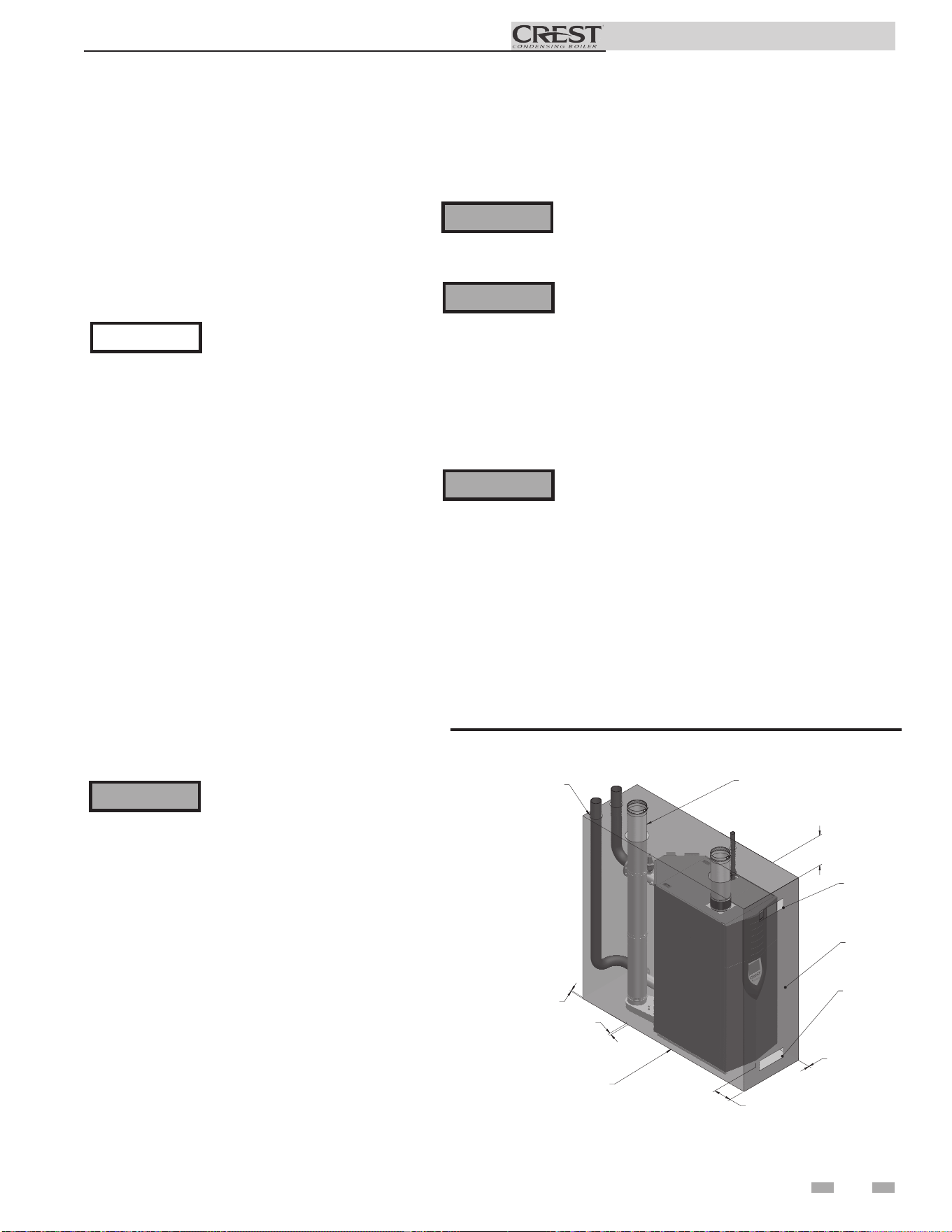
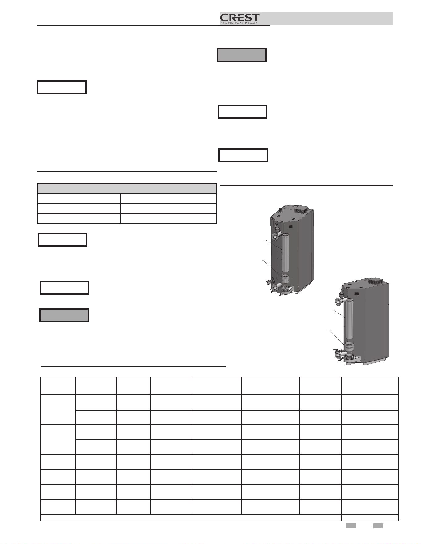
The Crest - How it works...
1. Front access panels
Provides access to the controls compartment.
2. Top access panel
Provides access to the burner compartment.
3. Air pressure switch
The air pressure switch detects blocked flue/vent conditions.
4. Blower
The blower pulls in air and gas through the venturi (item
34). Air and gas mix inside the blower and is pushed into the
burner, where they burn inside the combustion chamber.
5. Boiler drain connection
Location from which the heat exchanger can be drained.
6. Boiler inlet temperature sensor
The boiler inlet temperature sensor monitors system return
water temperature. If selected as the controlling sensor,
the control module will adjust the boiler firing rate so the inlet
temperature matches the set point.
7. Boiler outlet temperature sensor
The boiler outlet temperature sensor monitors boiler outlet
water temperature. If selected as the controlling sensor,
the control module will adjust the boiler firing rate so the outlet
temperature matches the set point.
8. Burner (not shown)
Single chamber design with a stress free metal fiber outer mesh
and durable stainless steel structure. Provides firing rates up to
15:1 turndown (Model 751), 20:1 turndown (Models 1001 -
1251 and 2501 - 3501), 25:1 turndown (Models 1501 - 2001),
12:1 turndown (Model 4001) and 10:1 turndown (Models 5001
- 6001).
9. Condensate drain connection
The condensate drain connection provides a connection
point to install a condensate drain line using flexible hose
provided.
10. Control module (on control panel assembly)
The control module responds to internal and external signals
and controls the blower, gas valves, and pump(s), depending on
the application, to meet the heating demand.
11. Electronic display
Digital controls with SMART TOUCH screen technology, full
color display, and an 8" user interface screen.
12. Flame inspection window
Two large high temperature quartz observation windows
provide views of the burner surface during firing.
13. Dual flame sensors (not shown)
Two flame sensors are provided to monitor the main burner
and transition flame.
14. Flue temperature sensor
The flue sensor monitors flue gas temperature. The control
module will modulate or shut the boiler down if the flue gas
temperature gets too high.
15. Gas connection pipe
The gas connection pipe is a threaded black iron pipe
connection (see Gas Connections Section for specific model
pipe size requirements). This pipe should be connected to the
incoming gas supply to deliver gas to the boiler.
16. Gas shutoff valve (inside unit)
The manual gas shutoff valve is used to isolate the boiler gas
train from the gas supply.
17. Gas valves
The gas valves sense the negative pressure created by the
blower, allowing gas to flow only if the gas valves are powered
and combustion air is flowing.
18. Condensate trap
The condensate trap is sized for a 1" PVC outlet connection
pipe.
19. High limit devices (primary and backup)
The high limit devices are used to monitor the outlet water
temperature - if either device senses the water temperature
exceeding the predetermined setting, the boiler will shut down.
20. Ignition electrode
An electrical spark across the electrodes will ignite the burner.
21. Line voltage junction box
The line voltage junction box contains the connection points for
the line voltage power to the boiler (and pumps if used).
22. Line voltage wiring connections (knockouts)
Conduit connection points for the high voltage junction box.
23. Low gas pressure switch
Monitors gas supply pressure to the boiler and shuts the boiler
down in the event a low gas pressure condition occurs.
24. High gas pressure switch
Monitors gas supply pressure to the boiler and shuts the boiler
down in the event a high gas pressure condition occurs.
25. Low voltage connection board(s)
Connection boards used to connect external low voltage devices.
26. Low voltage wiring connections (knockouts)
Conduit connection points for the low voltage connection boards.
27. Low water cutoff probe (LWCO) (not shown)
Ensures adequate water is supplied to the boiler. In the event of
inadequate water levels, the boiler will shut down.
28. Power switch
The On/Off power switch provides the ability to turn line voltage
power to the boiler on and off.
29. Relief valve
The safety relief valve protects the heat exchanger from an over
pressure condition. The boiler comes with a 50 PSI relief valve as
standard equipment. Optional settings are available.
30. Reset switch
Reset switch for the low water cutoff. Hold the switch for 10
seconds to reset.
31. Test switch
The test switch permits manual triggering of the LWCO
safety circuit to test the contacts and evaluate the integrity of the
circuit. Hold the switch for 10 seconds to test.
32. Firetube heat exchanger
High grade stainless steel WAVE
TM
firetube design that extracts
heat from flue gases and transfers it directly into boiler water.
33. Temperature and pressure gauge
Monitors the outlet temperature of the boiler as well as the system
water pressure.
34. Venturi
The venturi controls air and gas flow into the burner.
35. Water inlet
An ANSI flange connects the return water from the system to the
heat exchanger.
36. Water outlet
An ANSI flange connects the hot water supply from the boiler to
the system.
37. Ignition transformer
The transformer provides voltage to the ignition electrode (item
20).
38. Air arm temperature sensor (not shown)
Monitors fuel-air delivery temperature to the burner.
39. Air inlet cover (shipped loose)
Used with room air for combustion and to prevent debris from
entering the boiler.
40. Fuses
A low resistance resistor that acts as a sacrificial device to provide
over current protection, of either the load or source circuit.
41. Air metering valve
The air metering valve is used to control the amount of air used
when firing.
42. Air metering valve air pressure switch
The air metering valve air pressure switch is used to ensure the air
metering valve is open when firing gas valve 2.
43. Proof of closure valve (not shown)
An additional safety shutoff valve with proof of closure contacts is
used on the Crest 6.0 model only.
44. Combustion measurement port
Access point for combustion analyzer probe.
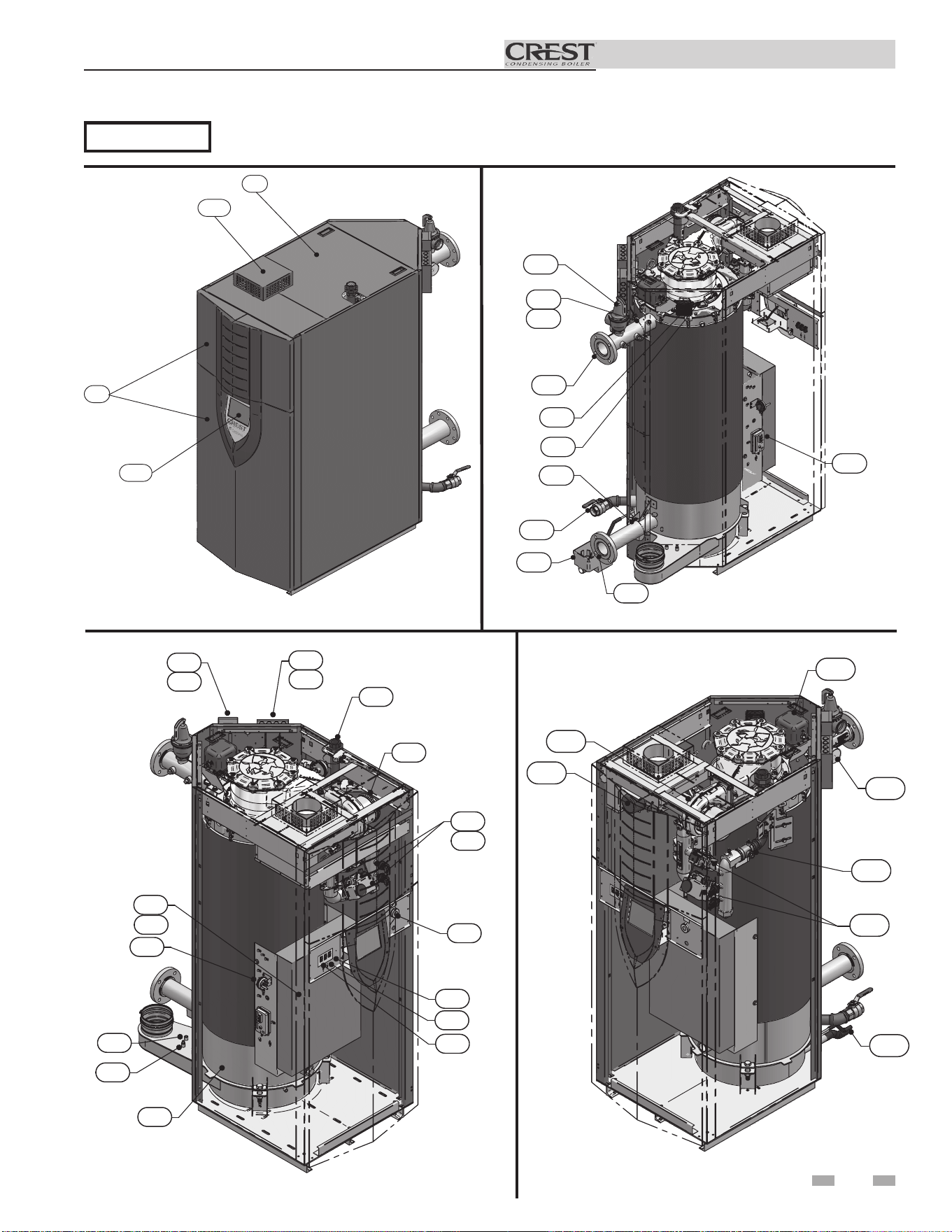
Right Side (inside unit)
The Crest - How it works... (continued)
5
Installation & Operation Manual
IMG01025
2
39
1
11
Front View
IMG01128
36
7
19
12
29
20
6
5
35
3
18
Rear View
IMG01130
33
17
16
34
37
9
41
IMG01129
25
26
21
22
15
4
30
31
28
14
32
10
40
42
24
23
19
44
Left Side (inside unit)
NOTICE
FBN1000 Series 100 model shown for illustration purposes only.
Installation & Operation Manual
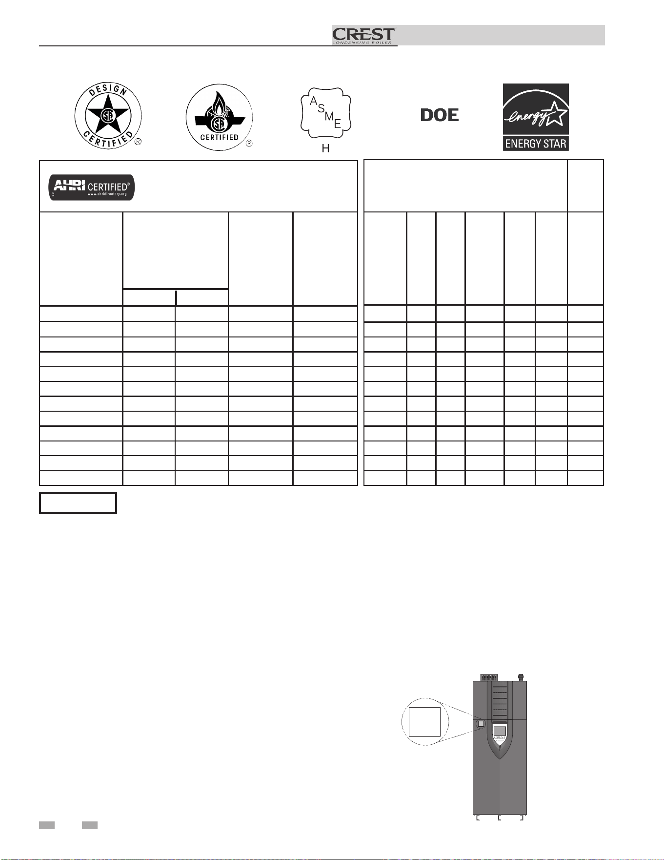
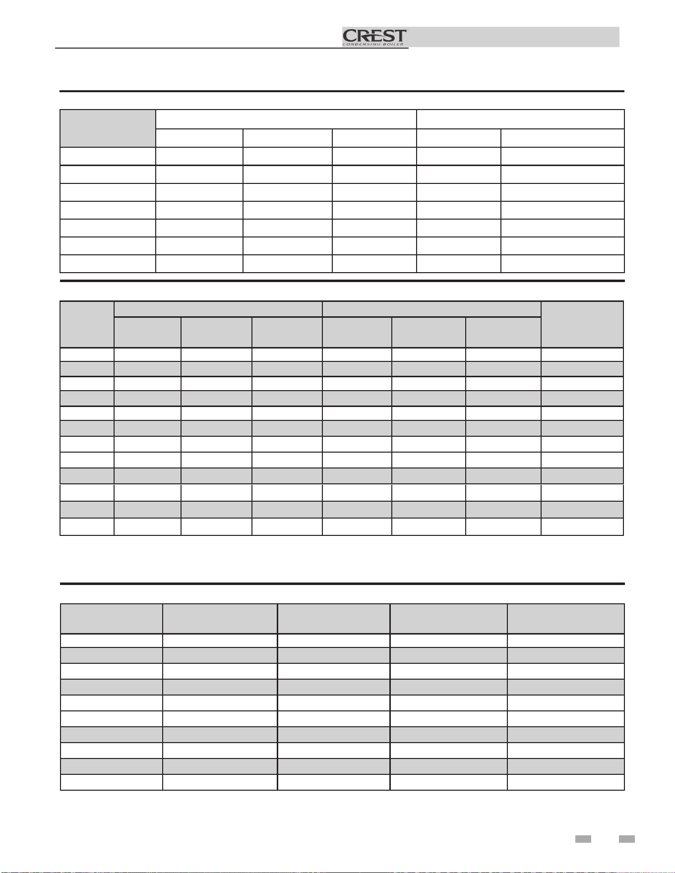
Ratings
Crest
AHRI Rating
Model Number
Note: Change “N” to
“L” for L.P. gas models.
Input
MBH
(Notes 4 - 6)
Min Max
Gross
Output
MBH
(Note 1)
Net
AHRI
Ratings
Water,
MBH
(Note 2)
FB(N,L)0751 50 750 722 626
FB(N,L)1001 50 999 961 834
FB(N,L)1251 62.5 1250 1203 1043
FB(N,L)1501 60 1500 1443 1252
FB(N,L)1751 70 1750 1684 1461
FB(N,L)2001 80 1999 1923 1699
FB(N,L)2501 125 2500 2400 2087
FB(N,L)3001 150 3000 2883 2507
FB(N,L)3501 175 3500 3364 2925
FB(N,L)4001 333.3 3999 3843 3342
FB(N,L)5001 499.9 4999 4804 4177
FB(N,L)6001 600 6000 5766 5014
Other Specifications
Appliance
Water
Content
Gallons
Pipe
Size
Outlet
Pipe
Size
Inlet
Gas Inlet
Size
Air
Size
Vent
Size
(Note 3)
Weight
w/Water
(lbs.)
73 3" 3" 1 1/4" 6" 6" 1768
77 3" 3" 1 1/4" 6" 6" 1838
87 3" 3" 1 1/2" 6" 8" 1975
94 4" 4" 1 1/2" 8" 8" 2307
106 4" 4" 1 1/2" 8" 8" 2458
111 4" 4" 1 1/2" 8" 8" 2570
157 4" 4" 2" 8" 9" 3600
156 4" 4" 2" 10" 10" 3900
202 4" 4" 2" 10" 10" 4600
201 4" 4" 2 1/2" 12" 12" 5200
254 6" 6" 2 1/2" 14" 14" 5900
304 6" 6" 3" 14" 14" 6900
Maximum allowed working pressure is located on the rating plate.
NOTICE
Notes:
1. The ratings are based on standard test procedures
prescribed by the United States Department of Energy.
2. Net AHRI ratings are based on net installed radiation of
sufficient quantity for the requirements of the building
and nothing need be added for normal piping and
pickup. Ratings are based on a piping and pickup
allowance of 1.15.
3. Crest boilers require special gas venting. Use only the vent
materials and methods specified in the Crest Installation
and Operation Manual
4. Standard Crest boilers are equipped to operate from sea
level to 4,500 feet only. The boiler will de-rate by 1.4% for
each 1,000 feet above sea level up to 4,500 feet.
5. High altitude Crest Models 0751-2001 are equipped to
operate from 3,000 to 12,000 feet only. The boiler will not
de-rate up to 5,500 feet and will de-rate by 1.6% for each
1,000 feet above 5,500 feet.
6. High altitude Crest Models 2501-5001 are equipped to
operate from 3,000 to 5,500 feet only. e boiler will not
de-rate up to 5,500 feet.
UNIT EQUIPPED FOR
HIGH ALTITUDE
3,000 FT. TO 12,000 FT.
IMG01026
Figure A High Altitude Label Location
7. High altitude Crest Model 6001 is equipped to operate from
3,000 to 5,500 feet only. e boiler will de-rate by 2% for
each 1000 feet above sea level.
8. For Crest Models 2501-6001 installations above 5,500 feet
contact the factory.
9. e operation given in this manual remains the same as
the standard boilers. A high altitude label (as shown in FIG
A.) is also axed to the unit. De-rate values are based on
proper combustion calibration and CO2’s adjusted to the
recommended levels.
10. Ratings have been conrmed by the Hydronics Section of
AHRI.
6
7
Installation & Operation Manual
Installation must comply with:
• Local, state, provincial, and national codes, laws,
regulations, and ordinances.
• National Fuel Gas Code, NFPA 54 / ANSI Z223.1 –
latest edition.
• Standard for Controls and Safety Devices for
Automatically Fired Boilers, ANSI/ASME CSD-1 -
latest edition, when required.
• National Electrical Code, NFPA 70 - latest edition.
• For Canada only: CSA B149.1 Installation Code,
CSA C22.1 Canadian Electrical Code Part 1 and any
local codes.
⚠WARNING
This appliance is certified as an indoor appliance. Do
not install the appliance outdoors or locate where the
appliance will be exposed to freezing temperatures.
Do not install the appliance where condensation may
form on the inside or outside of the appliance, or
where condensation may fall onto the appliance.
Failure to install the appliance indoors could result in
severe personal injury, death, or substantial property
damage.
1 Determine boiler location
The Crest gas manifold and
controls met safe lighting and other
performance criteria when the boiler
underwent tests specified in ANSI
Z21.13/CSA 4.9 – latest edition.
Before locating the boiler, check:
1. Check for nearby connection to:
• System water piping
• Venting connections
• Gas supply piping
• Electrical power
2. Locate the appliance so that if water connections
should leak, water damage will not occur. When
such locations cannot be avoided, it is
recommended that a suitable drain pan, adequately
drained, be installed under the appliance. The
pan must not restrict combustion air flow. Under no
circumstances is the manufacturer to be held
responsible for water damage in connection with
this appliance, or any of its components.
3. Check area around the boiler. Remove any
combustible materials, gasoline and other
flammable liquids.
This appliance requires a special venting system.
Use only the vent materials specified in this manual.
Failure to follow all instructions can result in flue gas
spillage and carbon monoxide emissions, causing
severe personal injury or death.
NOTICE
⚠WARNING
Failure to keep boiler area clear
and free of combustible materials,
4. The Crest must be installed so that gas control
system components are protected from dripping or
spraying water or rain during operation or service.
5. If a new boiler will replace an existing boiler, check
for and correct system problems, such as:
• System leaks causing oxygen corrosion or heat
exchanger cracks from hard water deposits.
• Incorrectly-sized expansion tank.
• Lack of freeze protection in boiler water causing
system and boiler to freeze and leak.
• Debris left from existing piping, if not flushed and
cleaned with an appropriate cleaner.
6. The appliance must be installed on a level floor,
both front to back and side to side, for proper
condensate drainage.
7. If the optional neutralizing kit is to be used, elevate
the boiler at least 3" above the floor.
Provide clearances:
Clearances from combustible materials
- Hot water pipes ........................................................... 1/4"
- Sides .............................................................................. 0"
- Rear ............................................................................... 0"
- Front ............................................................................. 0"
- Top ................................................................................ 0"
- Floor ........................................................... Combustible
- Vent pipe - Follow special vent system manufacturer’s instructions
⚠WARNING
VENTILATING*
AIR OPENING
VENTILATING*
CL
OSED DOOR
FLOOR: COMBUSTIBLE
IMG01027
0"
FRONT
0"
RIGHT
0"
TOP
VENT PIPE:
FOLLOW SPECIAL VENT SYSTEM
MANUFACTURER'S INSTRUCTIONS
1" (25 MM) MINIMUM CLEARANCE
A
ROUND HOT WATER PIPES
0"
REAR
0"
LEFT
Figure 1-1 Clearances
8. Check around the boiler for any potential air contaminants that
could risk corrosion to the boiler or the boiler combustion air supply
(see Table 1A on page 9). Prevent combustion air contamination.
Remove any of these contaminants from the boiler area.
DO NOT install units in rooms or environments that
contain corrosive contaminants (see Table 1A on page
9). Failure to comply could result in severe personal
injury, death, or substantial property damage.
⚠WARNING
gasoline, and other flammable liquids and vapors can
result in severe personal injury, death, or substantial
property damage.
Installation & Operation Manual
8
1 Determine boiler location
Provide air openings to room:
The Crest alone in boiler room
1. No air ventilation openings into the boiler room are
needed when clearances around the Crest are at least
equal to the SERVICE clearances shown in FIG. 1-1.
For spaces that do NOT supply this clearance, provide
two openings as shown in FIG. 1-1. Each opening must
provide one square inch free area per 1,000 Btu/hr of
boiler input.
2. Combustion air openings are required when using the
Room Air Option on page 28 of this manual.
The Crest in same space with other gas or oil-fired
appliances
1. Follow the National Fuel Gas Code (U.S.) or CSA B149.1
(Canada) to size/verify size of the combustion/ventilation
air openings into the space.
The space must be provided with
combustion/ventilation air openings
correctly sized for all other appliances
located in the same space as the Crest.
Failure to comply with the above warnings
could result in severe personal injury,
death, or substantial property damage.
2. Size openings only on the basis of the other appliances in
the space. No additional air opening free area is needed
for the Crest when it takes its combustion air from
outside (direct vent installation).
Do not install the boiler on carpeting even if
foundation is used. Fire can result, causing
severe personal injury, death, or substantial
property damage.
If flooding is possible, elevate the boiler sufficiently to prevent
water from reaching the boiler.
Flooring and foundation
Flooring
The Crest is approved for installation on combustible flooring,
but must never be installed on carpeting.
Vent and air piping
The Crest requires a special gas vent system, designed for
pressurized venting.
The boiler is to be used for either direct vent installation or
for installation using indoor combustion air. When room air
is considered, see page 28 of this manual. Note prevention of
combustion air contamination below when considering vent/
air termination.
Vent and air must terminate near one another and may be
vented vertically through the roof or out a side wall, unless
otherwise specified. You may use any of the vent/air piping
methods covered in this manual. Do not attempt to install
the Crest using any other means.
Be sure to locate the boiler such that the vent and air piping
can be routed through the building and properly terminated.
The vent/air piping lengths, routing and termination method
must all comply with the methods and limits given in this
manual.
Prevent combustion air contamination
Install air inlet piping for the Crest as described in this
manual. Do not terminate vent/air in locations that can
allow contamination of combustion air. Refer to Table 1A,
page 9 for products and areas which may cause contaminated
combustion air.
Ensure that the combustion air will not
contain any of the contaminants in Table
⚠WARNING
⚠WARNING
⚠WARNING
Assure that the floor and structure is
sufficient to support the installed weight
of the boiler, including the water content
in the heat exchanger. If not, structural
building failure will result, causing severe
personal injury, death, or substantial
property damage.
⚠WARNING
Recommended clearances for service access
- Sides .............................................................................. 24"
- Rear ............................................................................... 24"
- Front ............................................................................. 30"
- Top ................................................................................ 24"
If you do not provide the recommended
service clearances shown, it may not be
possible to service the boiler without
removing it from the space.
NOTICE
Maintain minimum specified clearances for adequate
operation. All installations must allow sufficient space for
servicing the vent connections, water pipe connections, piping
and other auxiliary equipment, as well as the appliance. The
clearance labels on each appliance note the same service and
combustible clearance requirements as shown in this manual.
Multiple boilers may be installed side by side with no clearance
between adjacent boilers because this boiler is approved for
zero clearance from combustible surfaces; however, service
access will be limited from the sides.
Consult the Venting section of this manual for specific
installation instructions for the appropriate type of venting
system that you will be using.
1A, page 9. Contaminated combustion air will damage the
boiler, resulting in possible severe personal injury, death
or substantial property damage. Do not pipe combustion
air near a swimming pool, for example. Also, avoid areas
subject to exhaust fumes from laundry facilities. These areas
will always contain contaminants.
Installation & Operation Manual
9
Products to avoid:
Spray cans containing chloro/fluorocarbons
Permanent wave solutions
Chlorinated waxes/cleaners
Chlorine-based swimming pool chemicals
Calcium chloride used for thawing
Sodium chloride used for water softening
Refrigerant leaks
Paint or varnish removers
Hydrochloric acid/muriatic acid
Cements and glues
Antistatic fabric softeners used in clothes dryers
Chlorine-type bleaches, detergents, and cleaning solvents
found in household laundry rooms
Adhesives used to fasten building products and other similar
products
Areas likely to have contaminants
Dry cleaning/laundry areas and establishments
Swimming pools
Metal fabrication plants
Beauty shops
Refrigeration repair shops
Photo processing plants
Auto body shops
Plastic manufacturing plants
Furniture refinishing areas and establishments
New building construction
Remodeling areas
Garages with workshops
Table 1A Corrosive Contaminants and Sources
1 Determine boiler location (continued)
Failure to follow all instructions can result
in flue gas spillage and carbon monoxide
emissions, causing severe personal injury
or death.
⚠WARNING
When using an existing vent system to
install a new boiler:
Check the following venting components before installing:
• Material - For materials listed for use with this appliance,
see Section 2 - General Venting, Table 2A-1. For stainless
steel venting, an adapter of the same manufacturer
(Table 2B) may be used at the flue collar connection.
• Size - To ensure proper pipe size is in place, see Table 2C.
Check to see that this size is used throughout the vent
system.
• Manufacturer - Only use the listed manufacturers and
their type product listed in Table 2A-1 for CAT IV positive
pressure venting with flue producing condensate.
• Supports - Non-combustible supports must be in place
allowing a minimum 1/4" rise per foot. The supports
should adequately prevent sagging and vertical slippage,
by distributing the vent system weight. For additional
information, consult the vent manufacturer’s
instructions for installation.
• Terminations - Carefully review Sections 2 through 4 to
ensure requirements for the location of the vent and air
terminations are met and orientation of these fit the
appropriate image from the Sidewall or Vertical
options listed in the General Venting Section.
• Seal - With prior requirements met, the system should be
tested to the procedure listed in parts (c) through (f) of
the Removal of an Existing Boiler Section on page 10.
With stainless steel vent, seal and connect all pipe and
components as specified by the vent manufacturer used.
⚠WARNING
If any of these conditions are not met,
the existing system must be updated or
replaced for that concern. Failure to
follow all instructions can result in flue gas
spillage and carbon monoxide emissions,
causing severe personal injury or death.
Installation & Operation Manual
1 Determine boiler location
10
When removing a boiler from existing
common vent system:
Do not install the Crest into a common
vent with any other appliance except
as noted in Section 2 on page 20.
This will cause flue gas spillage or
appliance malfunction, resulting in
possible severe personal injury, death,
or substantial property damage.
Failure to follow all instructions can
result in flue gas spillage and carbon
monoxide emissions, causing severe
personal injury or death.
a. Seal any unused openings in the common venting
system.
b. Visually inspect the venting system for proper size and
horizontal pitch and determine there is no blockage or
restriction, leakage, corrosion, or other deficiencies,
which could cause an unsafe condition.
c. Test vent system – Insofar as is practical, close all
building doors and windows and all doors between
the space in which the appliances remaining connected
to the common venting system are located and other
spaces of the building. Turn on clothes dryers and
any appliance not connected to the common venting
system. Turn on any exhaust fans, such as range
hoods and bathroom exhausts, so they will operate at
maximum speed. Do not operate a summer exhaust
fan. Close fireplace dampers.
d. Place in operation the appliance being inspected.
Follow the lighting instructions. Adjust thermostat so
appliance will operate continuously.
e. Test for spillage at the draft hood relief opening after
5 minutes of main burner operation. Use the flame of
a match or candle, or smoke from a cigarette, cigar, or
pipe.
f. After it has been determined that each appliance
remaining connected to the common venting system
properly vents when tested as outlined herein, return
doors, windows, exhaust fans, fireplace dampers, and
any other gas-burning appliance to their previous
conditions of use.
⚠ DANGER
⚠WARNING
At the time of removal of an existing boiler, the following
steps shall be followed with each appliance remaining
connected to the common venting system placed in
operation, while the other appliances remaining connected
to the common venting system are not in operation.
g. Any improper operation of the common venting system
should be corrected so the installation conforms with
the National Fuel Gas Code, ANSI Z223.1/NFPA 54
and/or CAN/CSA B149.1, Natural Gas and Propane
Installation Code. When re-sizing any portion of the
common venting system, the common venting system
should be resized to approach the minimum size as
determined using the appropriate tables in Part 11 of
the National Fuel Gas Code, ANSI Z223.1/NFPA 54
and/or CAN/CSA B149.1, Natural Gas and Propane
Installation Code.
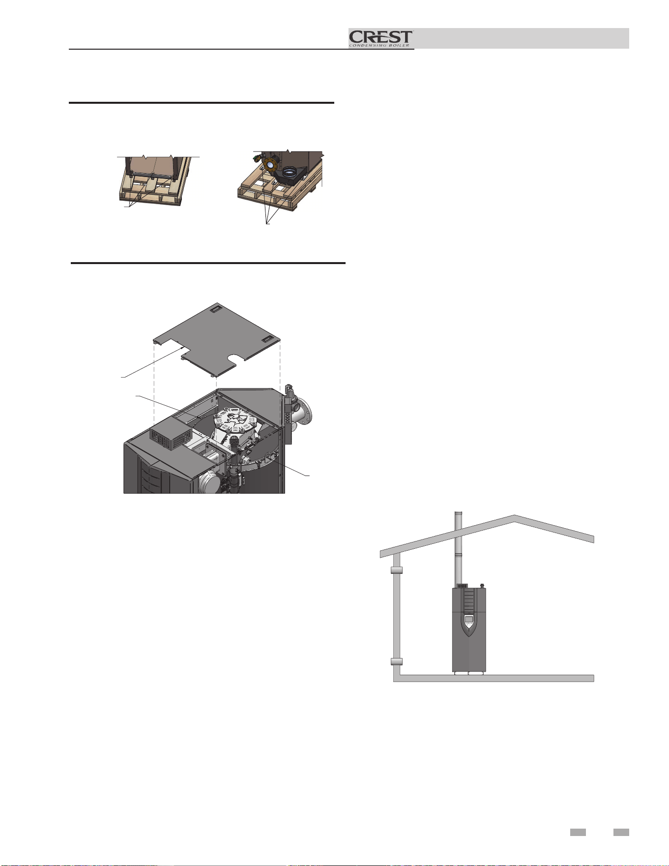
Remove boiler from wood pallet
1. After removing the outer shipping crate and plastic
from the boiler, remove the parts package (packaged
parts inside the controls compartment of the boiler
inside the lower front access panel).
2. To remove the boiler from the pallet:
a. Remove the three (3) shipping bolts located inside
the controls compartment securing the boiler to the
front of the pallet (see FIG. 1-2).
b. Remove the three (3) shipping bolts that fasten the
tie-down brackets securing the legs to the rear of the
pallet (FIG. 1-2).
c. The boiler can now be removed from the pallet
using a lift truck lifting from the front or rear of
the boiler. If lifting from the front, the lift truck
forks must extend at least half way under the boiler
heat exchanger to assure proper lifting technique
with no damage to the boiler.
d. If lifting by crane is desired, remove the top access
panels to gain access to the lifting lugs located on the
boiler (see FIG. 1-3). It is also recommended that the
upper and lower front panels along with both front
side panels be removed (no tools required).
Do not drop the boiler or bump the jacket
on the floor or pallet. Damage to the
boiler can result.
NOTICE
Failure to assure the truck forks are
long enough to extend at least halfway
under the boiler heat exchanger will
result in the boiler tipping off the lift
truck, and potentially falling. This will
result in severe personal injury, death, or
substantial property damage.
⚠WARNING
Installation & Operation Manual
1 Determine boiler location (continued)
IMG01028
LIFTIN
G
LUGS
LIFTING
LUGS
REMOVE MIDD
LE
TO
P COVER
Figure 1-3 Boiler Removed from Shipping Pallet
11
REAR
FRONT
BOLT, W
ASHERS
& LOC
KNUT (3X)
LAG BOLTS
& TABS
(3X)
Figure 1-2 Boiler Mounted on Shipping Pallet
Combustion and ventilation air
requirements for appliances drawing air
from the equipment room
Provisions for combustion and ventilation air must be in
accordance with Air for Combustion and Ventilation, of the
latest edition of the National Fuel Gas Code, NFPA 54 / ANSI
Z223.1, in Canada, the latest edition of CGA Standard B149
Installation Code for Gas Burning Appliances and Equipment,
or applicable provisions of the local building codes.
The equipment room MUST be provided with properly sized
openings and/or be of sufficient volume to assure adequate
combustion air and proper ventilation for all gas fired appliances
in the equipment room to assure adequate combustion air and
proper ventilation.
The requirements shown are for the appliance only; additional
gas fired appliances in the equipment room will require an
increase in the net free area and/or volume to supply adequate
combustion air for all appliances.
No combustion air openings are needed when the appliance is
installed in a space with a volume NO LESS than 50 cubic feet
per 1,000 Btu/hr of all installed gas fired appliances and the
building MUST NOT be of “Tight Construction”
3
.
A combination of indoor and outdoor combustion air may
be utilized by applying a ratio of available volume to required
volume times the required outdoor air opening(s) size(s). This
must be done in accordance with the National Fuel Gas Code,
NFPA 54 / ANSI Z223.1.
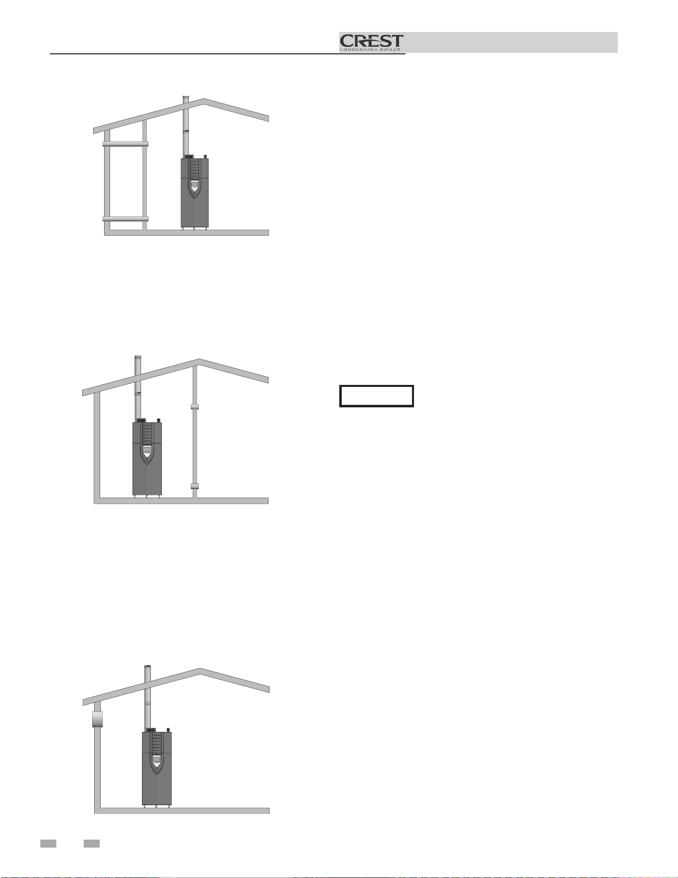
IMG01029
Figure 1-4_Combustion Air Direct from Outside
1. If air is taken directly from outside the building
with no duct, provide two permanent openings to
the equipment room each with a net free area of one square
inch per 4000 Btu/hr input (5.5 cm
2
per kW) (see FIG. 1-4).
1 Determine boiler location
Installation & Operation Manual
IMG01030
Figure 1-5_Combustion Air Through Ducts
2. If combustion and ventilation air is taken from the
outdoors using a duct to deliver the air to the
equipment room, each of the two openings should be
sized based on a minimum free area of one square inch
per 2000 Btu/hr (11 cm
2
per kW) of input (see FIG. 1-5).
IMG01031
Figure 1-6_Combustion Air from Interior Space
3. If air is taken from another interior space combined with
the equipment room:
(a) Two spaces on same story: Each of the two openings
specified above should have a net free area of one square
inch for each 1000 Btu/hr (22 cm
2
per kW) of input, but
not less than 100 square inches (645 cm
2
) (see FIG. 1-6).
(b) Two spaces on different stories: One or more openings
should have a net free area of two square inches per 1000
Btu/hr (44 cm
2
per kW).
4. If a single combustion air opening is provided to bring
combustion air in directly from the outdoors, the
opening must be sized based on a minimum free area
of one square inch per 3000 Btu/hr (7 cm
2
per kW). This
opening must be located within 12” (30 cm) of the top of
the enclosure (see FIG. 1-7).
All dimensions based on net free area in square inches. Metal
louvers or screens reduce the free area of a combustion air
opening a minimum of approximately 25%. Check with
louver manufacturers for exact net free area of louvers.
⚠CAUTION
Under no circumstances should the
equipment room ever be under negative
pressure. Particular care should be taken
where exhaust fans, attic fans, clothes dryers,
compressors, air handling units, etc., may
take away air from the unit.
The result is improper combustion and a non-warrantable,
premature appliance failure.
EXHAUST FANS: Any fan or equipment which exhausts air
from the equipment room may deplete the combustion air
supply and/or cause a downdraft in the venting system. Spillage
of flue products from the venting system into an occupied
living space can cause a very hazardous condition that must be
corrected immediately.
The combustion air supply must be completely free of any
flammable vapors that may ignite or chemical fumes which may
be corrosive to the appliance. Common corrosive chemical
fumes which must be avoided are fluorocarbons and other
halogenated compounds, most commonly present as refrigerants
or solvents, such as Freon, trichlorethylene, perchlorethylene,
chlorine, etc. These chemicals, when burned, form acids which
quickly attack the stainless steel heat exchanger, headers, flue
collectors, and the vent system.
Combustion air requirements are based on the latest edition
of the National Fuel Gas Code, NFPA 54 / ANSI Z223.1; in
Canada refer to the latest edition of CGA Standard CAN/CSA
B149.1. Check all local code requirements for combustion air.
Where two openings are provided, one must be within 12"
(30 cm) of the ceiling and one must be within 12" (30 cm) of
the floor of the equipment room. Each opening must have a
net free area as specified in Table 1B. Single openings shall
commence within 12" (30 cm) of the ceiling. The minimum
dimension of air openings shall not be less than 3" (80 mm).
IMG01032
Figure 1-7_Combustion Air from Outside - Single Opening
12
Installation & Operation Manual
1 Determine boiler location (continued)
The above requirements are for the appliance only; additional gas fired appliances in the equipment room will require an increase
in the net free area and/or volume to supply adequate combustion air for all appliances.
No combustion air openings are needed when the appliance is installed in a space with a volume NO LESS than 50 cubic feet per
1,000 Btu/hr of all installed gas fired appliances. Buildings MUST NOT be of *“Tight Construction”
3
.
1
Outside air openings shall directly communicate with the outdoors.
2
Combined interior space must be 50 cubic feet per 1,000 Btu/hr input. Buildings MUST NOT be of *“Tight Construction”.
3
”Tight Construction” is defined as a building with less than 0.40 ACH (air changes per hour). For buildings of “Tight
Construction”, provide air openings into the building from outside.
13
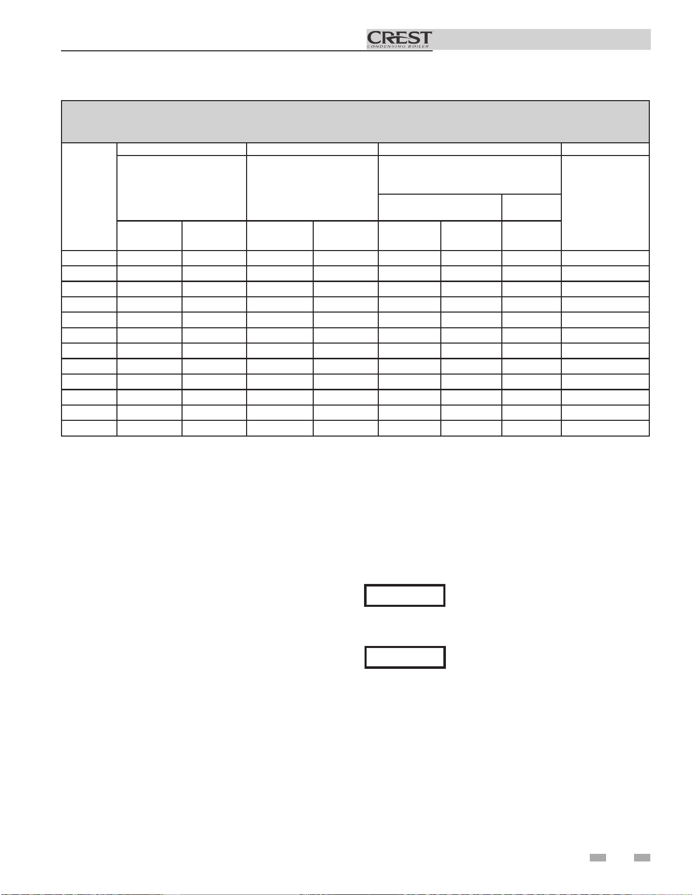
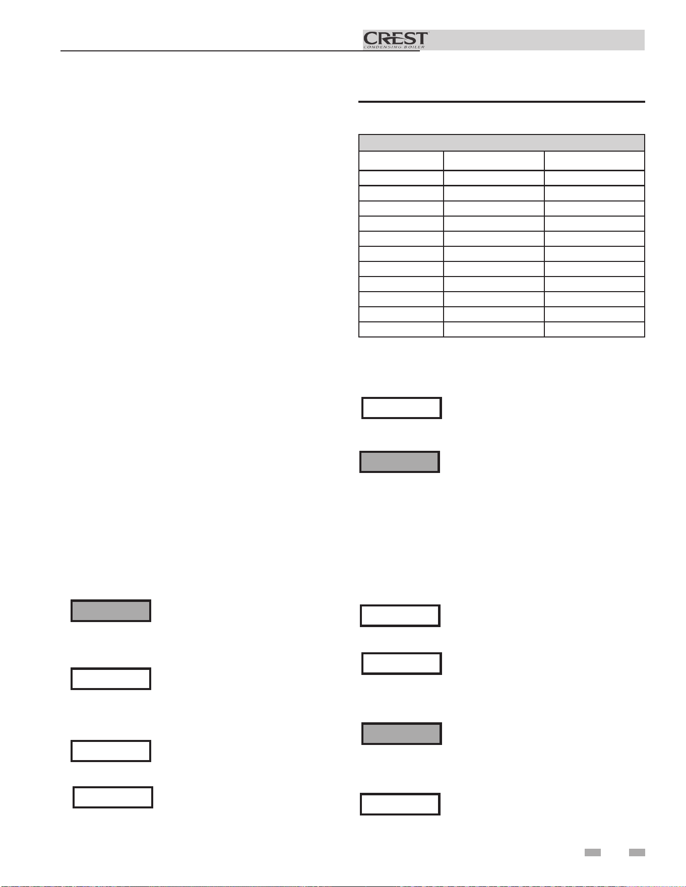
TABLE - 1B
MINIMUM RECOMMENDED COMBUSTION
AIR SUPPLY TO EQUIPMENT ROOM
Model
Number
FIG. 1-4 FIG. 1-5 FIG. 1-6 FIG. 1-7
*Outside Air from
2 Openings Directly from
Outdoors
1
*Outside Air from
2 Ducts Delivered from
Outdoors
1
Inside Air from
2 Ducts Delivered from Interior Space
2
*Outside Air from
1 Opening Directly
from Outdoors, in
2
(cm
2
)
1
Same Story
Different
Stories
Top
Opening, in
2
(cm
2
)
Bottom
Opening, in
2
(cm
2
)
Top
Opening, in
2
(cm
2
)
Bottom
Opening, in
2
(cm
2
)
Top
Opening, in
2
(cm
2
)
Bottom
Opening, in
2
(cm
2
)
Total
Openings, in
2
(cm
2
)
FB 0751 188 (1213) 188 (1213) 375 (2420) 375 (2420) 750 (4839) 750 (4839) 1500 (9678) 250 (1613)
FB 1001 250 (1613) 250 (1613) 500 (3226) 500 (3226) 1000 (6452) 1000 (6452) 2000 (12904) 333 (2149)
FB 1251 313 (2020) 313 (2020) 625 (4033) 625 (4033) 1250 (8065) 1250 (8065) 2500 (16129) 417 (2691)
FB 1501 375 (2420) 375 (2420) 750 (4839) 750 (4839) 1500 (9678) 1500 (9678) 3000 (19355) 500 (3226)
FB 1751 438 (2826) 438 (2826) 875 (5646) 875 (5646) 1750 (11291) 1750 (11291) 3500 (22581) 583 (3762)
FB 2001 500 (3226) 500 (3226) 1000 (6452) 1000 (6452) 2000 (12904) 2000 (12904) 4000 (25807) 667 (4304)
FB 2501 625 (4033) 625 (4033) 1250 (8065) 1250 (8065) 2500 (16129) 2500 (16129) 5000 (32258) 833 (5381)
FB 3001 750 (4839) 750 (4839) 1500 (9678) 1500 (9678) 3000 (19355) 3000 (19355) 6000 (38710) 1000 (6452)
FB 3501 875 (5646) 875 (5646) 1750 (11291) 1750 (11291) 3500 (22581) 3500 (22581) 7000 (45162) 1167 (7530)
FB 4001 1000 (6450) 1000 (6450) 2000 (12900) 2000 (12900) 4000 (25800) 4000 (25800) 8000 (51600) 1333 (8600)
FB 5001 1250 (8062) 1250 (8062) 2500 (16129) 2500 (16129) 5000 (32250) 5000 (32250) 10000 (64500) 1667 (10750)
FB 6001 1500 (9677) 1500 (9677) 3000 (19355) 3000 (19355) 6000 (38710) 6000 (38710) 12000 (77419) 2000 (12903)
CAUTION
During construction the air filter should be
checked more frequently to ensure it does
not become clogged with combustion dirt
and debris.
NOTICE
Sustained operation of an appliance with
a clogged burner may result in nuisance
operational problems, bad combustion, and
non-warrantable component failures.
Combustion air filter
This unit has a standard air filter located at the combustion air
inlet. This air filter is provided to help ensure clean air is used
for the combustion process. Check this filter every month and
replace when it becomes dirty. You can find these commercially
available filters at any home center or HVAC supply store.
Filters by model sizes:
FBN0751-1251 / 14 x 14 x 1 filter
FBN1501-3501 / 16 x 20 x 1 filter
FBN4001-6001 / 20 x 24 x 1 filter
Note: Replacement filter should have a MERV rating no greater
than 4.
Follow the steps below when replacing the combustion air filter:
1. Locate the combustion air filter box.
2. Lift and remove the air filter box cover to gain access to the
air filter.
3. Slide the air filter out the top of the air filter box.
4. Inspect the air filter for dirt and debris, replace if necessary.
5. Replace the air filter and the air filter box cover.
14
Installation & Operation Manual
Vertical
IMG01033
2 General venting
IM
G01059
IM
G01056
Sidewall
Direct venting
Vertical Vent, Sidewall Air
Sidewall
IM
G01057
Vertical
IMG01058
Optional room air

15
Installation & Operation Manual
2 General venting (continued)
Install vent and combustion air piping
⚠ DANGER
The Crest must be vented and supplied
with combustion and ventilation air as
described in this section. Ensure the vent
and air piping and the combustion air
supply comply with these instructions
regarding vent system, air system, and
combustion air quality. See also Section 1
of this manual.
Inspect finished vent and air piping
thoroughly to ensure all are airtight and
comply with the instructions provided
and with all requirements of applicable
codes.
Failure to provide a properly installed
vent and air system will cause severe
personal injury or death.
Air inlet pipe materials:
The air inlet pipe(s) must be sealed. Choose acceptable
combustion air inlet pipe materials from the following list:
ABS, PVC, or CPVC
Dryer Vent or Sealed Flexible Duct (not recommended
for rooftop air inlet)
Galvanized steel vent pipe with joints and seams sealed
as specified in this section.
Type “B” double-wall vent with joints and seams sealed
as specified in this section.
AL29-4C, stainless steel material to be sealed to
specification of its manufacturer.
*Plastic pipe may require an adapter (not provided) to
transition between the air inlet connection on the appliance
and the plastic air inlet pipe.
⚠WARNING
Using vent or air intake materials other
than those specified, failure to properly
seal all seams and joints or failure to follow
vent pipe manufacturer’s instructions can
result in personal injury, death or property
damage. Mixing of venting materials will
void the warranty and certification of the
appliance.
NOTICE
The use of double-wall vent or insulated
material for the combustion air inlet
pipe is recommended in cold climates
to prevent the condensation of airborne
moisture in the incoming combustion air.
Sealing of Type “B” double-wall vent material or galvanized
vent pipe material used for air inlet piping on a sidewall or
vertical rooftop Combustion Air Supply System:
a. Seal all joints and seams of the air inlet pipe using either
Aluminum Foil Duct Tape meeting UL Standard 723 or
181A-P or a high quality UL Listed silicone sealant such
as those manufactured by Dow Corning or General
Electric.
b. Do not install seams of vent pipe on the bottom of
horizontal runs.
c. Secure all joints with a minimum of three sheet metal
screws or pop rivets. Apply Aluminum Foil Duct Tape or
silicone sealant to all screws or rivets installed in the vent
pipe.
d. Ensure that the air inlet pipes are properly supported.
The PVC, CPVC, or ABS air inlet pipe should be cleaned and
sealed with the pipe manufacturer’s recommended solvents
and standard commercial pipe cement for the material used.
The ABS, PVC, CPVC, Dryer Vent or Flex Duct air inlet pipe
should use a silicone sealant to ensure a proper seal at the
appliance connection and the air inlet cap connection. Dryer
vent or flex duct should use a screw type clamp to seal the
vent to the appliance air inlet and the air inlet cap. Proper
sealing of the air inlet pipe ensures that combustion air will be
free of contaminants and supplied in proper volume.
16
Installation & Operation Manual
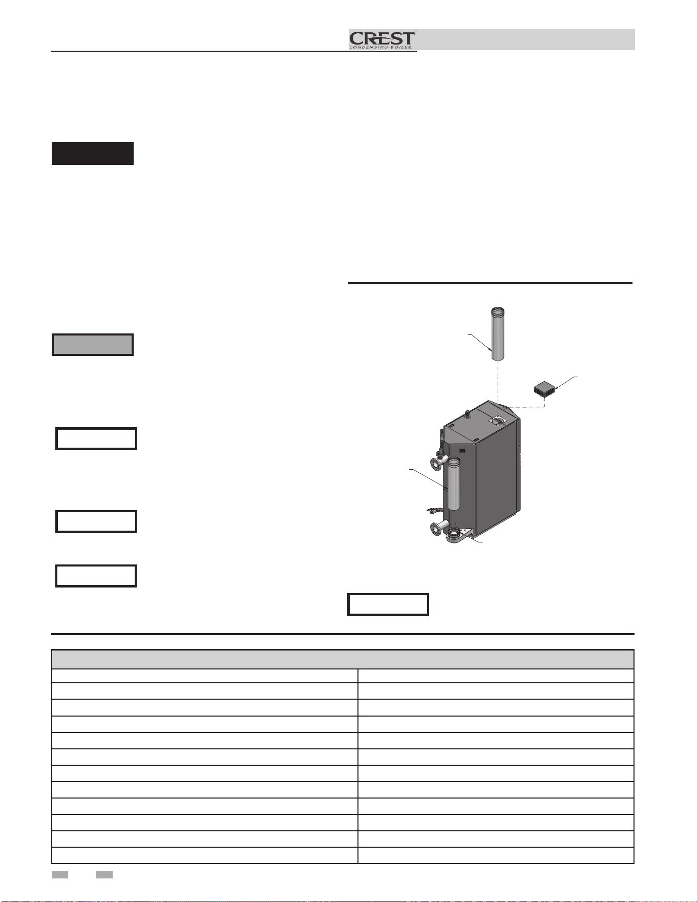
Air intake/vent connections
1. Combustion Air Intake Connector (FIG. 2-1) - Used to
provide combustion air directly to the unit from outdoors.
A fitting is provided with the unit for final connection.
Combustion air piping must be supported per guidelines
listed in the National Mechanical Code, Section 305, Table
305.4 or as local codes dictate.
2. Vent Connector (FIG. 2-1) - Used to provide a
passageway for conveying combustion gases to the
outside. A transition fitting is provided on the unit for
final connection. Vent piping must be supported per the
National Building Code, Section 305, Table 305.4 or as
local codes dictate.
IMG01034
ROOM AIR BO
X
SHIPPED WITH
UNIT
AIR PIPE
(FIELD SUPPLIED)
VENT PIPE
(FIELD SUPPLIED)
CONNECTO
R SIZED FOR STAINLESS STEEL
FLUE PIPE
Figure 2-1 Combustion Air Adapter
Vent and air piping
The Crest is certified as a Category II/IV boiler. This product
has been approved for use with stainless steel vent systems.
All venting systems used with a Crest boiler must be suitable
for Category IV operation except for factory approved
common vent systems operating as allowed in the Common
Venting Section on page 20.
⚠WARNING
NOTICE
NOTICE
When a sidewall or vertical rooftop combustion air supply
system is disconnected for any reason, the air inlet pipe
must be resealed to ensure that combustion air will be free of
contaminants and supplied in proper volume.
⚠ DANGER
Failure to properly seal all joints and seams
as required in the air inlet piping may
result in flue gas recirculation, spillage
of flue products and carbon monoxide
emissions causing severe personal injury
or death.
The Crest uses model specific combustion air intake and vent
piping sizes as detailed in Tables 2B and 2C on page 18.
Increasing or decreasing combustion air
or vent piping to sizes not specified in this
manual is not authorized.
NOTICE
2 General venting
Use only the materials, vent systems,
and terminations listed in Table 2A-1.
DO NOT mix vent systems of different
types or manufacturers, unless listed in
this manual. Failure to comply could
result in severe personal injury, death, or
substantial property damage.
Installations must comply with applicable
national, state, and local codes. Stainless
steel vent systems must be listed as a
UL-1738 approved system for the United
States and a ULC-S636 approved system
for Canada.
Installation of a stainless steel vent system
should adhere to the stainless steel vent
manufacturer’s installation instructions
supplied with the vent system.
NOTICE
The Crest is supplied with an integral
FasNSeal vent connector (FIG. 2-1). The
installer must use a specific vent starter
adapter supplied by the vent manufacturer
to adapt to different vent systems.
Table 2A-1 Approved Stainless Steel Vent Manufacturers
Approved Stainless Steel Vent Manufacturers
Make Model
ProTech Systems (Dura-Vent Co.) FasNSeal Vent
Z-Flex (Nova Flex Group) Z-Vent
Heat Fab (Selkirk Corporation) Saf-T Vent
Metal Fab Corr/Guard
Securities Chimneys International Secure Seal SS
DuraVent DuraSeal DS
Schebler Chimney Systems eVent
ICC VIC
Jeremias --
Enervex Powerstack
Van Packer --
17
Installation & Operation Manual
2 General venting (continued)
Table 2A-2 Approved Stainless Steel Terminations and Adapters - Category IV
Model
ProTech Z Flex Heat Fab
Adapter Intake Adapter Intake Adapter Flue Intake
751-1001
Not Required 810003269 2SVSAFNS06 2SVEE0690 9601MAD CCK06TM 9690 / 9692
1251
*See note 810003281 2SVSAFNS06 2SVEE0690 9801MAD CCK08TM 9690 / 9692
1501-2001
*See note 810003357 / 810003369 2SVSAFNS08 2SVEE0890 9801MAD CCK08TM 9890 / 9892
Model
Metal-Fab Security Chimney ICC
Adapter Flue Intake Adapter Flue Intake Adapter Flue Intake
751-1001
6FCGPVCA
MC
6-36"
6FCGSW90L SS6PVCU
SS0MCU
4" - 24"
SS6ST90AU
SSD0STAUK
4" - 24"
HM-06CA78
HM-06SCR-F
HM-06RC-F
HE-06E90-F
HM-06SCR-F
1251
8FCGLCA
MC
6-36"
6FCGSW90L SS8CRESTU
SS0MCU
4" - 24"
SS6ST90AU
SSD0STAUK
4" - 24"
HM-08CA78
HM-08SCR-F
HM-08MC-F
HE-06E90-F
HM-06SCR-F
1501-2001
8FCGLCA
MC
6-36"
8FCGSW90 SS8CRESTU
SS0MCU
4" - 24"
SSE8E9OU
SD0STAUK
4" - 24"
HM-08CA78
HM-08SCR-F
HM-08MC-F
HE-08E90-F
HM-08SCR-F
Model
Jeremias DuraVent
Adapter Flue Intake Adapter Flue Intake
751-1001
SWKL6-KLC SWKL6-WRC SWKL6-90ET DS6PVCU
DS0MCU
4″ - 24″
DS6ST90AU DSD0STAUK
4" - 24"
1251
SWKL8-KLC SWKL8-WRC SWKL6-90ET DS8CRESTU
DS0MCU
4″ - 24″
DS6ST90AU DSD0STAUK
4" - 24"
1501-2001
SWKL8-KLC SWKL8-WRC SWKL8-90ET DS8CRESTU
DS0MCU
4″ - 24″
DSE8E90U DS0ST90AUK
4" - 24"
*No adapter needed when using 8” FasNSeal vent length.
*Models 1251 - 1501: For installations using a 6 inch vent, use the adapter from Table 2A-2 for the appropriate vent system
manufacturer, then use the manufacturer’s tapered reducing adapter from 8 inch to 6 inch diameter to continue system. If using
a DuraVent vent system, factory KIT #100295900 is available. For Models 751-1001, reference the manufacturer’s part number
provided.
18
Installation & Operation Manual
2 General venting
Table 2A-2 Approved Stainless Steel Terminations and Adapters - Category IV (continued)
Model
ProTech Z Flex Heat Fab
Adapter Intake Adapter Intake Adapter Flue Intake
2501
*See note 810003397 / 810003409 2SVSAFNS09 2SVEE990 9901MAD CCK09TM 9890 / 9992
3001 - 3501
*See note 810003435 / 810003447 2SVSAFNS10 2SVEE1090 91001MAD CCK10TM 91090 / 91092
4001
*See note 810003476 / 810003488 2SVSAFNS12 2SVEE1290 91201MAD CCK12TM 91290 / 91292
5001 - 6001
*See note 810003516 / 810003528 2SVSAFNS14 2SVEE1490 91401MAD CCK14TM 91490 / 91492
Model
Metal-Fab Security Chimney ICC
Adapter Flue Intake Adapter Flue Intake Adapter Flue Intake
2501
8FCGLCA
MC
6-36"
8FCGSW90 SS9CRESTU
SS0MCU
4" - 24"
SSE9E9OU
SDOST90AUK
4" - 10"
HM-09CA78
HM-09SCR-F
HM-09MC-F
HE-08E90-F
HM-08SCR-F
3001 - 3501
10FCGLCA
MC
6-36"
10FCGSW90 SS10CRESTU
SS0MCU
4" - 24"
SSE10E9OU
SDOST90AUK
4" - 10"
HM-10CA78
HM-10SCR-F
HM-10MC-F
HE-10E90-F
HM-10SCR-F
4001
12FCGLCA
MC
6-36"
12FCGSW90 SS12CRESTU
SS0MCU
4" - 24"
SSE12E9OU HM-12CA78
HM-12SCR-F
HM-12MC-F
HE-12E90-F
HM-12SCR-F
5001 - 6001
14FCGLCA
MC
6-36"
14FCGSW90 SS14CRESTU
SS0MCU
4" - 24"
SSE14E9OU HM-14CA78
HM-14SCR-F
HM-14MC-F
HE-14E90-F
HM-14SCR-F
Model
Jeremias DuraVent
Adapter Flue Intake Adapter Flue Intake
2501
SWKL9-KLC SWKL9-WRC SWKL9-90ET DS9CRESTU
DS0MCU
4″ - 24″
DSE9E90U DS0ST90AUK
4” - 10”
3001 - 3501
SWKL10-KLC SWKL10-WRC SWKL10-90ET DS10CRESTU
DS0MCU
4″ - 24″
DSE10E90U DS0ST90AUK
4” - 10”
4001
SWKL12-KLC SWKL12-WRC SWKL12-90ET DS12CRESTU
DS0MCU
4″ - 24″
DSE12E90U
5001 - 6001
SWKL14-KLC SWKL14-WRC SWKL14-90ET DS14CRESTU
DS0MCU
4″ - 24″
DSE14E90U
*No adapter needed when using Standard FNS Vent Length
19
Installation & Operation Manual
2 General venting
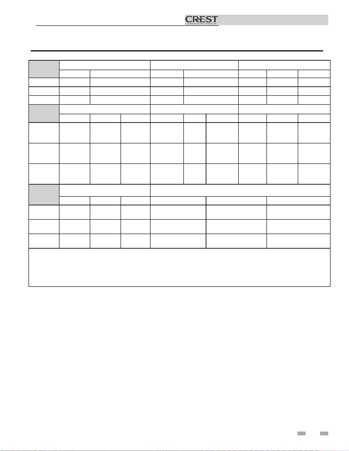
Table 2B Direct Vent Minimum / Maximum Allowable Air / Vent Lengths
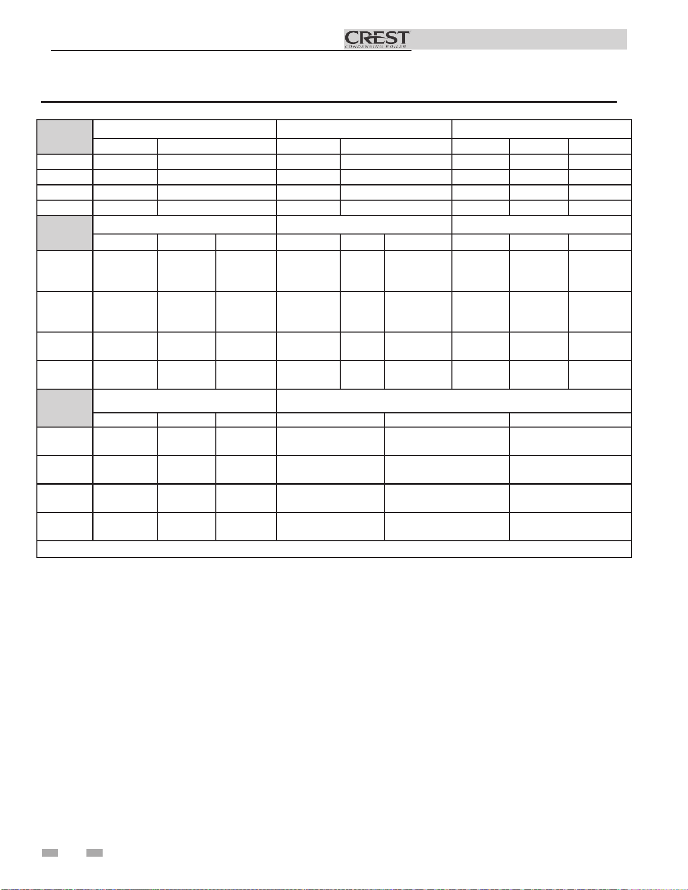
Table 2C Room Air Minimum / Maximum Allowable Air / Vent Lengths
Model
AIR INLET VENT
Input
De-Rate per
25 feet of Vent
Air Intake
Diameter
Air Intake
Min. Length
Air Intake
Max. Length
Vent
Diameter
Vent
Min. Length
Vent
Max. Length
0751-1001 6" 12' 100' 6" 18' 100' 0%
1251* 6" 12' 75' 6" 18' 75' 1%
1251 6" 12' 100' 8" 18' 100' 0%
1501* 8" 12' 75' 6" 18' 75' 1%
1501 8" 12' 100' 8" 18' 100' 0%
1751-2001 8" 12' 100' 8" 18' 100' 0%
2501 8" 12' 100' 9" 18' 100' 0%
2501* 8" 12ʹ 100ʹ 10" 18ʹ 100ʹ 0%
3001 10" 12' 100' 10" 18' 100' 0%
3501 10" 12' 100' 10" 18' 100' 0%
4001 12" 12' 100' 12" 18' 100' 0%
5001/6001 14" 12' 100' 14" 18' 100' 0%
Model
Vent
Diameter
Vent
Min. Length
Vent
Max. Length
Input De-Rate per
25 feet of Vent
0751-1001 6" 18' 100' 0%
1251-1501* 6" 18' 100' 0%
1251-1501 8" 18' 100' 0%
1751-2001 8" 18' 100' 0%
2501 9" 18' 150' 0%
2501* 10" 18ʹ 150ʹ 0%
3001 10" 18' 150' 0%
3501 10" 18' 150' 0%
4001 12" 18' 150' 0%
5001/6001 14" 18' 150' 0%
*FB 1251 - 1501 models using 6" vent require the installation of a eld supplied reducing adapter (see Table 2A-2 on page 17).
*FB 1251 - 1501 LP models using 6" diameter vent will de-rate 2.5% per 25 feet of vent.
*FB 2501 models using 10" vent diameter option must use appropriate increase adapters as needed.
*FB 1251 - 1501 models using 6" vent require the installation of a eld supplied reducing adapter (see Table 2A-2 on page 17).
*FB 1251 - 1501 LP models using 6" diameter vent will de-rate 2.5% per 25 feet of vent.
*FB 2501 models using 10” vent diameter option must use appropriate increase adapters as needed.
Model
Enervex Van Packer
Adapter Flue Intake Adapter Intake
751-1001 801.0676.4706 801.0679.XX06 801.0676.0406 MM06MOAB MM0690EB & M06SCTB
1251 801.0676.4708 801.0679.XX08 801.0676.0408 MM08MOAB M0690EB & M06SCTB
1501-2001 801.0676.4708 801.0679.XX08 801.0676.0408 MM08MOAB M0890EB & M06SCTB
2501 801.0676.4709 801.0679.XX10 801.0676.0408 MM09MOAB M0890EB & M06SCTB
3001-3501 801.0676.4710 801.0679.XX10 801.0676.0410 MM10MOAB M1090EB & M06SCTB
4001 801.0676.4712 801.0679.XX12 801.0676.0412 MM12MOAB M1290EB & M06SCTB
5001 801.0676.4712 801.0679.XX12 801.0676.0412 MM14MOAB M1490EB & M06SCTB
Table 2A-2 Approved Stainless Steel Terminations and Adapters - Category IV (continued)
20
Installation & Operation Manual
Vent, air piping and termination:
The Crest vent and air piping can be installed through the roof
or through a sidewall. Follow the procedures in this manual for
the method chosen. Refer to the information in this manual to
determine acceptable vent and air piping length.
Air contamination
Pool and laundry products and common household and hobby
products often contain fluorine or chlorine compounds. When
these chemicals pass through the boiler, they can form strong
acids. The acid can eat through the boiler wall, causing serious
damage and presenting a possible threat of flue gas spillage or
boiler water leakage into the building.
Please read the information given in Table 1A, page 9,
listing contaminants and areas likely to contain them. If
contaminating chemicals will be present near the location of the
boiler combustion air inlet, have your installer pipe the boiler
combustion air and vent to another location, per this manual.
If the boiler combustion air inlet is located
in a laundry room or pool facility, for
example, these areas will always contain
hazardous contaminants.
To prevent the potential of severe personal
injury or death, check for areas and products
listed in Table 1A, page 9 before installing
the boiler or air inlet piping.
If contaminants are found, you MUST:
• Remove products permanently.
—OR—
• Relocate air inlet and vent
terminations to other areas.
Removing from existing vent
Follow the instructions in Section 1, page 10 of this manual
when removing a boiler from an existing vent system.
Vent and air piping
Vent and air system:
Installation must comply with local
requirements and with the National Fuel
Gas Code, NFPA 54 / ANSI Z223.1 for U.S.
installations or CSA B149.1 for Canadian
installations.
You must also install air piping from outside to the boiler
air intake adapter. The resultant installation is direct vent
(sealed combustion).
You may use any of the vent/air piping methods covered in
this manual. Do not attempt to install the Crest using any
other means.
NOTICE
⚠WARNING
⚠WARNING
⚠WARNING
When determining equivalent combustion air and vent
length, add 5 feet (1.5m) for each 90° elbow and 3 feet (.9 m)
for each 45° elbow.
EXAMPLE: 20 feet (6 m) of pipe + (4) 90° elbows + (3) 45°
elbows = 49 equivalent feet (15 m) of piping.
2 General venting (continued)
DO NOT mix components from different
systems. The vent system could fail,
causing leakage of flue products into the
living space. Use only approved stainless
steel pipe and fittings.
When installing outdoor models OF(N,L),
reference the Outdoor Crest Supplemental
Manual for further information.
NOTICE
Installation & Operation Manual
21
2 General venting
Common venting
Crest boilers may be common vented; however, the following
criteria MUST BE followed:
1. Only Crest boilers may be connected to common flue
applications. DO NOT mix other manufacturer’s
appliances or other Lochinvar models. Common air
intake is not allowed.
2. Crest boilers connected to the common vent must all be
of the same size.
3. Each Crest boiler must have a Lochinvar supplied flue
damper installed (see Table 2D).
4. A condensate drain must be installed above the flue
damper.
5. Only vertical direct vent, positive pressure, Category
IV or vertical/chimney vent, negative pressure, Category
II may be used when common venting Crest boilers.
Sidewall venting is not allowed.
6. Crest boilers in a common vent must be connected and
controlled with the integral Crest SMART TOUCH
Cascade.
a. The Leader may be controlled through the Crest
SMART TOUCH control through BMS (external
0 - 10V signal), ModBus or its own internally
calculated set point.
b. The Cascade (Members) must be controlled by the
Crest Leader boiler using the Lead/Lag Cascade
option.
For approved common vent sizing, contact the factory.
⚠WARNING
When Crest boilers are common vented,
the criteria above MUST BE followed.
Failure to follow all these requirements
will result in severe personal injury, death,
or substantial property damage.
Table 2D Flue Damper Kits
Flue Damper Kits
Model Damper Size Kit Number
FB0751 6" 100352523
FB1001 6" 100352523
FB1251 8" 100141561
FB1501 8" 100141561
FB1751 8" 100141561
FB2001 8" 100141561
FB2501 9" 100141562
FB3001 10" 100141563
FB3501 10" 100141563
FB4001 12" 100141564
FB5001/6001 14" 100141565
NOTICE
When Crest boilers are common vented,
hot water generators MUST BE piped
to the primary heating loop and tank
thermostats must not be connected to the
Crest.
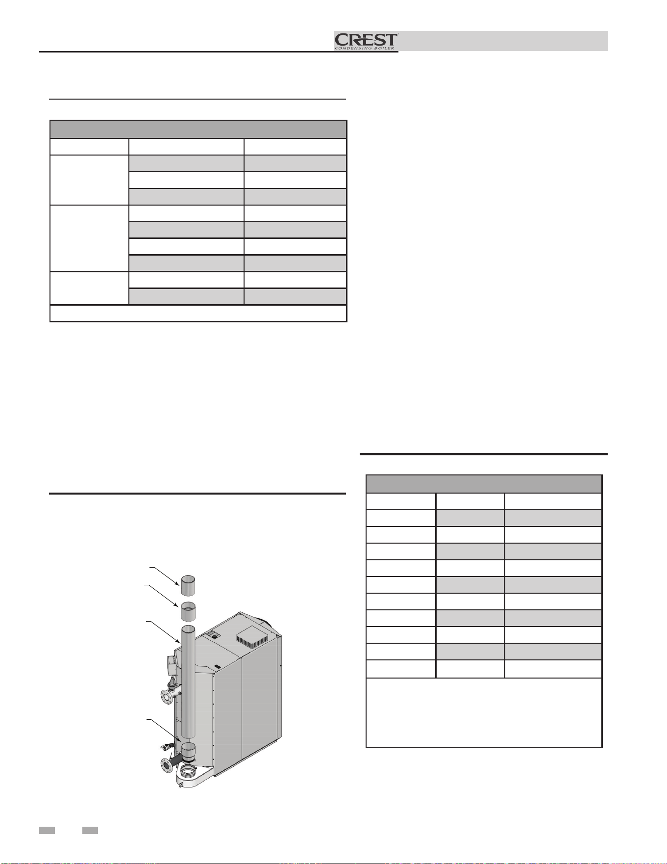
Installing vent and air piping
Use only cleaners, primers, and solvents
that are approved for the materials which
are joined together.
NOTICE
PVC/CPVC (Models 751 - 4001 only)
All PVC vent pipes must be glued, properly
supported, and the exhaust must be
pitched a minimum of a 1/4 inch per foot
back to the boiler (to allow drainage of
condensate).
NOTICE
⚠WARNING
The vent connection to the appliance must
be made with a minimum of 10 equivalent
feet of CPVC pipe (field provided). The
field provided vent fittings must be
cemented to the CPVC pipe section using
an “All Purpose Cement” suitable for
PVC and CPVC pipe. Use only the vent
materials, primer, and cement specified
in Table 2E to make the vent connections.
Failure to follow this warning could result
in fire, personal injury, or death.
⚠WARNING
Insulation should not be used on PVC
or CPVC venting materials. The use of
insulation will cause increased vent wall
temperatures, which could result in vent
pipe failure.
This product has been approved for use with the PVC/CPVC
vent materials listed in Table 2E on page 21.
Factory installed vent connections are sized
for stainless steel venting.
NOTICE
NOTICE
A field supplied inline condensate
collection section MUST BE installed
directly above the backflow preventer.
NOTICE
When using polypropylene common vent
on Models 751 - 3501, a field supplied
polypropylene to stainless steel adapter
MUST BE installed between the backflow
preventer and the unit connection.
CPVC vent or stainless steel pipe and vent
fittings must be used in closet and alcove
installations.
NOTICE
Installation & Operation Manual
22
2 General venting (continued)
5. Dry fit vent or air piping to ensure proper fit up
before assembling any joint. The pipe should go
a third to two-thirds into the fitting to ensure
proper sealing after cement is applied.
6. Priming and Cementing:
a. Handle fittings and pipes carefully to prevent
contamination of surfaces.
b. Apply a liberal even coat of primer to the fitting
socket and to the pipe end to approximately 1/2"
beyond the socket depth.
c. Apply a second primer coat to the fitting
socket.
d. While primer is still wet, apply an even coat of
approved cement to the pipe equal to the
depth of the fitting socket along with an even
coat of approved cement to the fitting socket.
e. Apply a second coat of cement to the pipe.
f. While the cement is still wet, insert the pipe into
the fitting, if possible twist the pipe a 1/4 turn as
you insert it. NOTE: If voids are present,
sufficient cement was not applied and joint could
be defective.
g. Wipe excess cement from the joint removing
ring or beads as it will needlessly soften the
pipe.
Table 2E PVC/CPVC Vent Pipe and Fittings
Approved PVC/CPVC Vent Pipe and Fittings
Item Material Standard
Vent pipe
PVC Schedule 40, 80 ANSI/ASTM D1785
PVC - DWV ANSI/ASTM D2665
CPVC Schedule 40, 80 ANSI/ASTM F441
Vent fittings
PVC Schedule 40 ANSI/ASTM D2466
PVC Schedule 80 ANSI/ASTM D2467
CPVC Schedule 80 ANSI/ASTM F439
PVC - DWV ANSI/ASTM D2665
Pipe Cement /
Primer
PVC ANSI/ASTM D2564
CPVC ANSI/ASTM F493
NOTICE: DO NOT USE CELLULAR (FOAM) CORE PIPE
NOTE: In Canada, CPVC and PVC vent pipe, ttings and cement/
primer must be ULC-S636 certied.
1. Work from the boiler to vent or air termination. Do not
exceed the lengths given in this manual for the air or vent
piping.
2. Cut pipe to the required lengths and deburr the inside
and outside of the pipe ends.
3. Chamfer outside of each pipe end to ensure even
cement distribution when joining.
4. Clean all pipe ends and fittings using a clean dry rag.
(Moisture will retard curing and dirt or grease will prevent
adhesion.)
DIR #2000557608 00
PVC PIPE
(FIELD SUPPLIED)
PVC COUPLING
(FIELD SUPPLIED)
MINIMUM OF
10 EQUIVALENT
FEET OF CPVC
(FIELD SUPPLIED)
STAINLESS ADAPTER
(FIELD SUPPLIED
AS NEEDED)
NOTE: CPVC VENT
OR STAINLESS STEEL
PIPE
AND VENT FITTINGS MUST BE USED
IN CLOSET
AND ALCOVE INSTALLATIONS.
Figure 2-2 Near Boiler PVC/CPVC Venting (Flue connections from
the factory are sized for stainless steel venting.)
PVC Adapter Kits
Model Vent Size Kit Number
751-1001 6" 100289537
1251 6" 100289537
1251 8" 100267012
1501 6" 100289537
1501 8" 100267012
1751-2001 8" 100267012
2501* 10" 100316610
3001 10" 100314852
3501 10" 100314852
4001 12" Field Supplied
*Adapts 9" SS to 10" CPVC/PVC
NOTICE: A MINIMUM OF 10 EQUIVALENT
FEET OF CPVC (FIELD SUPPLIED) MUST BE
INSTALLED DIRECTLY AFTER ADAPTER IN
ALL APPLICATIONS
Table 2F PVC Adapter Kits
Installation & Operation Manual
23
2 General venting
Model Manufacturer Vent Model Vent Type Adapter Number Joint Connector Sidewall Kit*
Retaining Bracket /
Adapter*
751-1001
Centrotherm
Eco Systems
Innoflue
Single-Wall
Flex
ISSALE0606 -- --
IATP0606 /
ISTAGL0606
DuraVent
(M & G)
PolyPro
Single-Wall
Flex
FSA-06M-6PPF -- 6PPS-HLKL --
1251-2001
Centrotherm
Eco Systems
Innoflue Single-Wall ISSA0808 -- -- --
DuraVent
(M & G)
PolyPro Single-Wall FSA-08M-8PPF -- 8PPS-HSTL --
2501
Centrotherm Innoflue Single-Wall ISSA0910 -- -- --
3001-3501
Centrotherm
Eco Systems
Innoflue Single-Wall ISSA1010 -- -- --
4001
Centrotherm Innoflue Single-Wall ISSA1212 N/A N/A N/A
5001-6001
N/A N/A N/A N/A N/A N/A N/A
* These parts are only needed if the sidewall termination assembly is used (see FIG. 4-1C on page 26).
Polypropylene (Models 751 - 4001 only)
This product has been approved for use with polypropylene
vent with the manufacturers listed in Table 2G.
All terminations must comply with listed options in this
manual and be a single-wall vent offering.
For support and special connections required, see the
manufacturer's instructions. All vent is to conform to standard
diameter and equivalent length requirements established.
When determining equivalent combustion air and vent length
for polypropylene single-wall piping contact the manufacturer.
Use only the adapters and vent system listed
in Tables 2G and 2H. DO NOT mix vent
systems of different types or manufacturers.
Failure to comply could result in severe
personal injury, death, or substantial
property damage.
⚠WARNING
Installations must comply with applicable
national, state, and local codes. For
Canadian installation, polypropylene vent
must be listed as a ULC-S636 approved
system.
Installation of a polypropylene vent system
should adhere to the vent manufacturer’s
installation instructions supplied with the
vent system.
Table 2G Polypropylene Vent Pipe and Fittings
⚠WARNING
Insulation should not be used on
polypropylene venting materials. The use
of insulation will cause increased vent wall
temperatures, which could result in vent pipe
failure.
The installer must use a specific vent starter
adapter at the flue collar connection. The
adapter is supplied by the vent manufacturer
to adapt to its vent system. See Table 2G for
approved vent adapters.
NOTICE
All vent connections MUST be secured by
the vent manufacturer's joint connector
(FIG. 2-3).
NOTICE
Figure 2-3 Near Boiler Polypropylene Venting
IM
G01149
POLYPROPYLENE
PIPE (FIELD SUPPLIED)
POLYPROPYLENE
ADAPTER (FIELD
SUPPLIED)
MODELS 1251 - 3501
IMG01148
POLYPROPYLENE
PIPE (FIELD SUPPLIED)
PO
LYPROPYLENE
A
DAPTER (FIELD
SUPPLIED)
MODELS 751 - 1001
NOTICE
NOTICE
Table 2H Approved Polypropylene Terminations
Approved Polypropylene Vent Manufacturers
Make Model
Centrotherm Eco Systems
InnoFlue SW/Flex
Duravent (M & G Group)
PolyPro Single-Wall / PolyPro Flex
Factory installed vent connections are sized
for stainless steel venting.
NOTICE
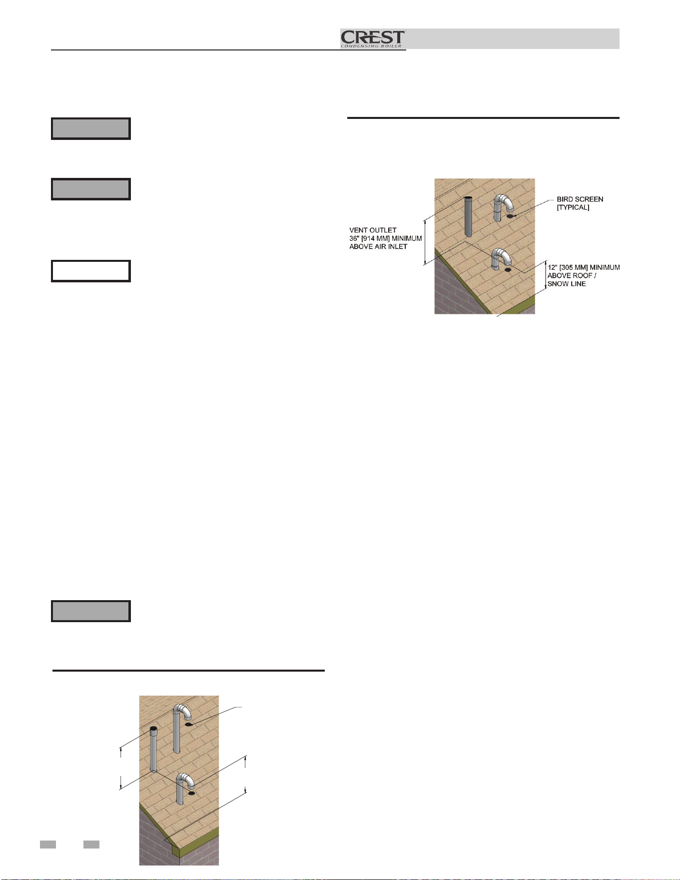
Installation & Operation Manual
3 Vertical direct venting
Vent/air termination – vertical
Prepare roof penetrations
1. Air pipe penetration:
a. Cut a hole for the air pipe. Size the air pipe hole as
close as desired to the air pipe outside diameter.
2. Vent pipe penetration:
a. Cut a hole for the vent pipe. For either combustible
or noncombustible construction, size the vent pipe
hole per the vent manufacturer’s instructions.
b. Insert a galvanized metal thimble in the vent pipe
hole (when required by local codes).
3. Space the air and vent holes to provide the minimum
spacing shown in FIG. 3-1.
4. Follow all local codes for isolation of vent pipe when
passing through floors, ceilings, and roofs.
5. Provide flashing and sealing boots sized for the vent pipe
and air pipe.
Termination and fittings
1. Prepare the vent termination coupling and the air
termination elbow (FIG. 3-1) by inserting bird screens.
Bird screens should be obtained locally.
2. The air piping must terminate in a down-turned 180°
return bend as shown in FIG. 3-1. Locate the air inlet
pipe no further than 2 feet (.6 m) from the center of the
vent pipe. This placement avoids recirculation of flue
products into the combustion air stream.
5. Locate terminations so they are not likely to be damaged
by foreign objects, such as stones or balls, or subject to
buildup of leaves or sediment.
⚠WARNING
Figure 3-2 Vertical Termination of Air and Vent w/Rain
Cap
Follow instructions below when determining
vent location to avoid possibility of severe
personal injury, death or substantial property
damage.
Installation must comply with local
requirements and with the National Fuel
Gas Code, NFPA 54 / ANSI Z223.1 - latest
edition for U.S. installations or CSA B149.1
Installation Code for Canadian installations.
⚠WARNING
NOTICE
⚠WARNING
Do not connect any other appliance to the
vent pipe or multiple boilers to a common
vent pipe except as noted in Section 2 on
page 20. Failure to comply could result in
severe personal injury, death, or substantial
property damage.
Determine location
Locate the vent/air terminations using the following guidelines:
1. The total length of piping for vent or air must not exceed
the limits given in the General Venting Section on page 18
of this manual.
2. The vent must terminate at least 3 feet above the highest
place in which the vent penetrates the roof and at least 2 feet
above any part of a building within 10 horizontal feet.
3. The air piping must terminate in a down-turned 180° return
pipe no further than 2 feet (.6 m) from the center of the vent
pipe. This placement avoids recirculation of flue products
into the combustion air stream.
4. The vent piping must terminate in an up-turned coupling
as shown in FIG. 3-1. The top of the coupling or the rain
cap must be at least 36" (914 mm) above the air intake. The
air inlet pipe and vent pipe can be located in any desired
position on the roof, but must always be no further than 2
feet (.6 m) apart and with the vent termination at least 36"
(914 mm) above the air intake.
Rooftop vent and air inlet terminations must
terminate in the same pressure zone, unless
vertical vent sidewall air is set up as shown
in the General Venting - Vertical Vent,
Sidewall Air Section.
BIRD SCREEN
[TYPICAL]
VENT OUTLET
36" MINIMUM
A
BOVE AIR INLET
VENT
COMBUSTION AIR
12" [305 MM] MINIMUM
ABOVE ROOF /
SNOW LINE
Figure 3-1 Vertical Termination of Air and Vent
24
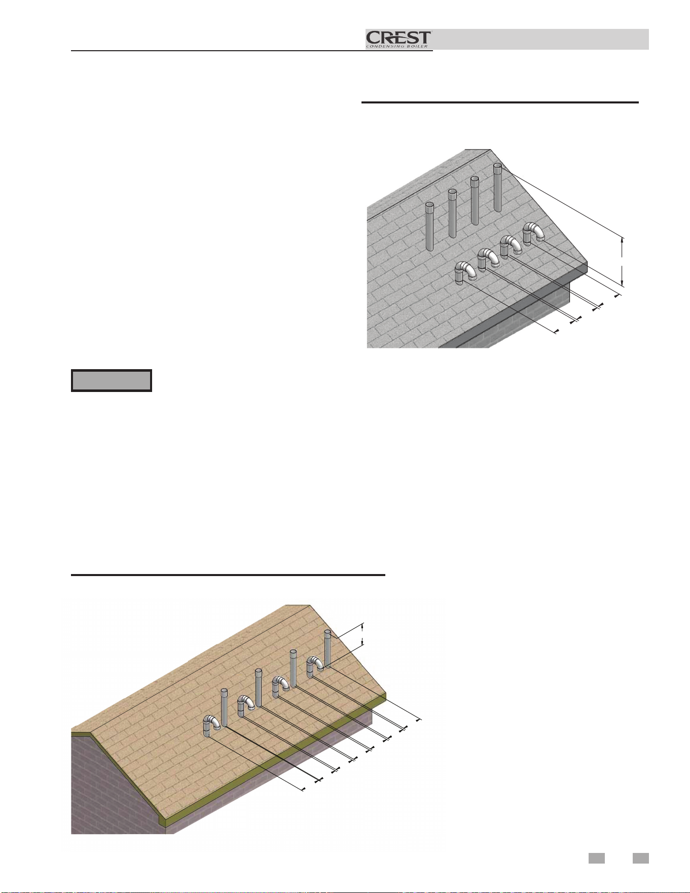
25
Installation & Operation Manual
3 Vertical direct venting
Multiple vent/air terminations
1. When terminating multiple Crest boilers, terminate
each vent/air connection as described in this manual
(FIG. 3-3).
Terminate all vent pipes at the same
height and all air pipes at the same height
to avoid recirculation of flue products and
the possibility of severe personal injury,
death, or substantial property damage.
2. Place roof penetrations to obtain minimum clearance of
36 inches (914 mm) between edge of air intake elbow and
adjacent vent pipe of another boiler for U.S. installations
(see FIG. 3-3). For Canadian installations, provide
clearances required by CSA B149.1 Installation Code.
3. The air inlet of a Crest boiler is part of a direct vent
connection. It is not classified as a forced air intake with
regard to spacing from adjacent boiler vents.
12” (305 MM)
12”
(305 MM)
12”
(305 MM)
12”
(305 MM)
12”
(305 MM)
12”
(305 MM)
12”
(305 MM)
12”
(305 MM)
DIR# 2000539525
36” (914 MM)
Figure 3-3 Vertical Terminations with Multiple Boilers
36” (914 MM)
12”
(305 MM)
12”
(305 MM)
12”
(305 MM)
DIR# 2000539526
Figure 3-4 Alternate Vertical Terminations with Multiple
Boilers
⚠WARNING
3. The vent piping must terminate in an up-turned coupling
as shown in FIG. 3-1. The top of the coupling or the
rain cap must be at least 36" (914 mm) above the air
intake. The air inlet pipe and vent pipe can be located
in any desired position on the roof, but must always be
no further than 2 feet (.6 m) apart and with the vent
termination at least 36" (914 mm) above the air intake.
4. Maintain the required dimensions of the finished
termination piping as shown in FIG. 3-1.
5. Do not extend exposed vent pipe outside of building
more than shown in this document. Condensate could
freeze and block vent pipe.
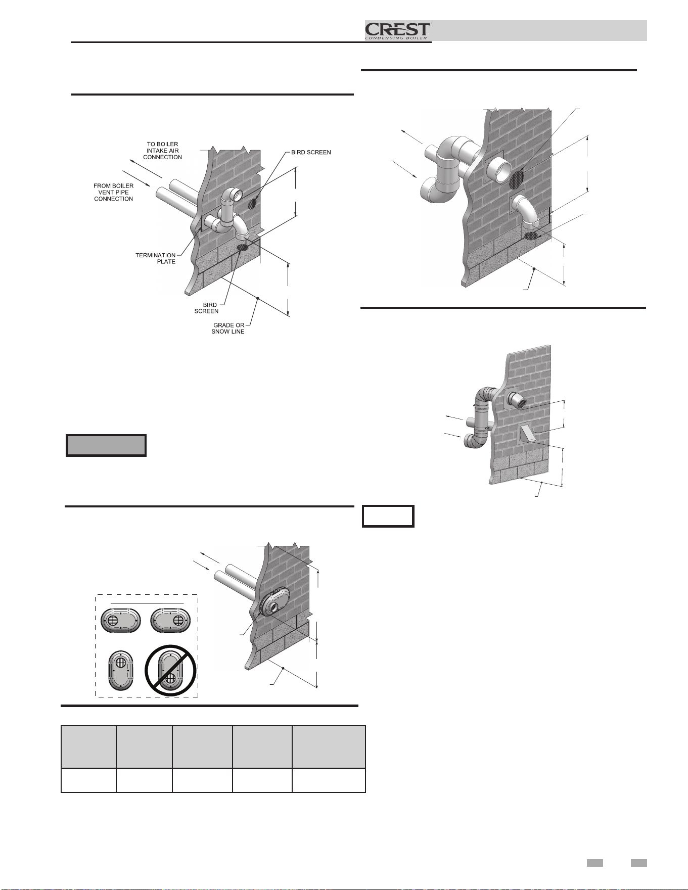
27
Installation & Operation Manual
4 Sidewall direct venting
Vent/air termination – sidewall
TO BOILER
INTAKE AIR
CONNECTION
FROM BOILER
VENT PIPE
CONNECTION
VENT / AIR
TERMINATION
GRADE OR
SNOW LINE
12"
MIN
12"
MIN
TO
OVER-
HANG
POSSIBLE ORIENTATIONS
Figure 4-1C PVC/CPVC/Polypropylene Sidewall
Termination of Air and Vent (Models 751 - 1001 only)
Do not exceed the maximum lengths of the
outside vent piping shown in FIG. 4-1C.
Excessive length exposed to the outside could
cause freezing of condensate in the vent pipe,
resulting in potential boiler shutdown.
⚠WARNING
3. The air piping must terminate in a down-turned elbow as
shown in FIG. 4-1B. This arrangement avoids recirculation
of flue products into the combustion air stream.
4. The vent piping must terminate in an elbow pointed outward
or away from the air inlet, as shown in FIG. 4-1B.
36” (914 MM) MIN
12” (305 MM)
MIN
Figure 4-1B PVC/CPVC/ Polypropylene Sidewall
Termination of Air and Vent w/Field Supplied Fittings
(Models 751 - 3501 only)
Model Kit # Air Vent
Centerline
Width
751 - 1001 100157612 6" (152 mm) 6" (152 mm) 7 3/4" (197 mm)
Table 4A Sidewall Vent Kits
TO BOILER INTAKE
AIR CONNECTION
FROM BOILER VENT
PIPE CONNECTION
36" (914 MM) MIN
12" (305 MM) MIN
GRADE OR
SNOW LINE
Figure 4-2B Stainless Steel Sidewall Termination w/Field
Supplied Fittings (Models 751 - 6001 only)
36" (914 MM) MIN
12" (305 MM) MIN
FROM BOILER
VENT PIPE
CONNECTION
TO BOILER
INTAKE AIR
CONNECTION
BIRD SCREEN
BIRD SCREEN
GRADE OR
SNOW LINE
Figure 4-2A PVC/CPVC/ Polypropylene Sidewall
Termination w/Field Supplied Fittings (Models 751 - 3501 only)
PVC/CPVC or ABS is acceptable air inlet pipe material.
NOTICE
5. Maintain clearances as shown in FIG.’s 4-1A thru 4-4,
pages 25 thru 27. Also maintain the following:
a. Vent must terminate:
• At least 6 feet (1.8 m) from adjacent walls.
• No closer than 12 inches (305 mm) below roof
overhang.
• At least 7 feet (2.1 m) above any public walkway.
• At least 3 feet (.9 m) above any forced air intake
within 10 feet (3 m).
• No closer than 4 feet (1.2 m) below or
horizontally from any door or window or any other
gravity air inlet.
b. Air inlet must terminate at least 12 inches (305 mm)
above grade or snow line; at least 3 feet (.9 m)
below the vent termination (FIG. 4-1B); and the vent
pipe must not extend more than 24 inches (610 mm)
vertically outside the building.
c. Do not terminate closer than 4 feet (1.2 m)
horizontally from any electric meter, gas meter,
regulator, relief valve, or other equipment. Never
terminate above or below any of these within 4 feet
(1.2 m) horizontally.
6. Locate terminations so they are not likely to be damaged
by foreign objects, such as stones or balls, or subject to
buildup of leaves or sediment.
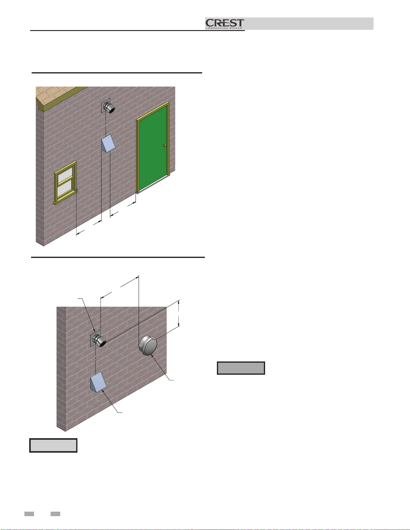
Termination and fittings
1. The air termination must be oriented at least 12 inches
above grade or snow line as shown in FIG. 4-1A, page
25.
2. Maintain the required dimensions of the finished
termination piping as shown in FIG. 4-1A, page 25.
3. Do not extend exposed vent pipe outside of the
building more than what is shown in this document.
Condensate could freeze and block vent pipe.
4. Stainless steel terminations are designed to penetrate
walls with a thickness up to 9.25 inches of standard
construction.
All vent pipes and air inlets must
terminate at the same height to avoid
possibility of severe personal injury,
death, or substantial property damage.
Multiple vent/air terminations
1. When terminating multiple Crest boilers terminate
each vent/air connection as described in this manual
(FIG. 4-5).
⚠WARNING
28
Installation & Operation Manual
4 Sidewall direct venting (continued)
Vent/air termination – sidewall
4'
4'
Figure 4-3 Clearance to Doors and Windows
VENT
TERMINATION
IF LESS THAN 10’
36” MIN.
FORCED
AIR
INLET
AIR TERMINATION
Figure 4-4 Clearance to Forced Air Inlets
Prepare wall penetrations
1. Air pipe penetration:
a. Cut a hole for the air pipe. Size the air pipe hole as
close as desired to the air pipe outside
diameter.
Vent pipe penetration:
a. Cut a hole for the vent pipe. For either combustible
or noncombustible construction, size the vent pipe
hole per the vent manufacturer’s instructions.
2. Install the vent and air intake piping. Seal all gaps
between the pipes and wall with RTV silicone sealant.
3. Seal all wall cavities.
⚠ CAUTION
Sidewall venting commercial products will
result in large exhaust plumes in cold
climates. Consideration should be taken
when locating in proximity to windows,
doors, walkways, etc.
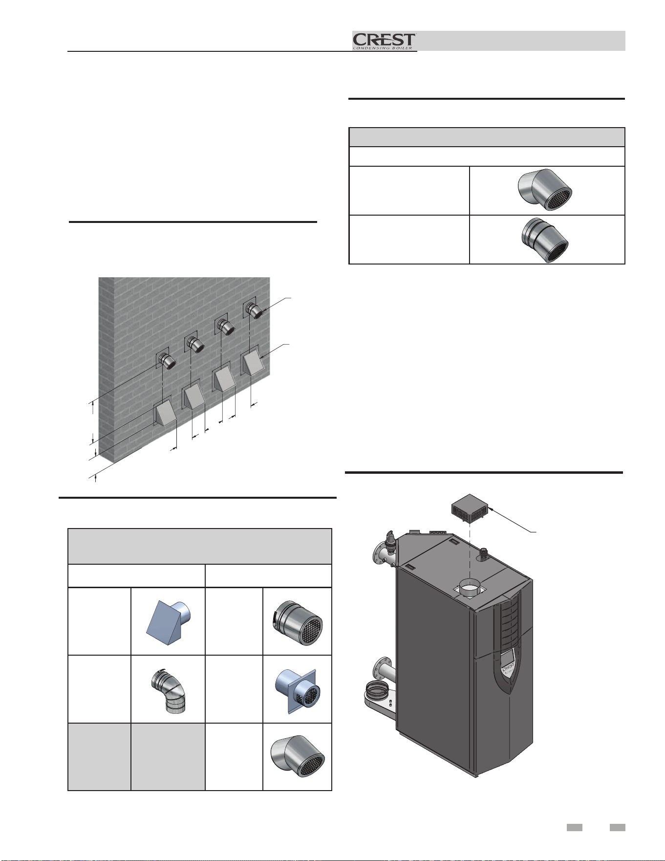
Installation & Operation Manual
4 Sidewall direct venting
2. Place wall penetrations to obtain minimum clearance
of 36 inches (914 mm) between vent pipe and adjacent
air inlet, as shown in FIG. 4-5 for U.S. installations. For
Canadian installations, provide clearances required by
CSA B149.1 Installation Code.
3. The air inlet of a Crest is part of a direct vent
connection. It is not classified as a forced air intake
with regard to spacing from adjacent boiler vents.
12" MIN
36" MIN
12"
12"
12"
AIR
VENT
DIR# 2000539531
Figure 4-5 Multiple Vent Terminations (must also
comply with Figure 4-1A)
DIRECT VENT TERMINATIONS
Air Inlet Vent Termination
Dryer Inlet Straight
90° Elbow Mitered
23° Elbow
Figure 4-6 Direct Vent Terminations
ROOM AIR (DIRECT EXHAUST TERMINATIONS)
Vent Termination
23° Elbow
45° Elbow
Figure 4-7 Room Air (Direct Exhaust Terminations)
Room air
IMG01036
AIR INLET COVER
Figure 4-8 Room Air Installation
The Crest boiler may be installed with a single pipe carrying the
flue products to the outside while using combustion air from
the equipment room.
Follow the requirements in the General Venting, Sidewall
Direct Venting, and Vertical Direct Venting sections for vent
material specifications, vent length requirements, and vent
termination requirements.
Install the air inlet cover (shipped loose with the boiler) per
FIG. 4-8. Combustion and ventilation air must be supplied to
the equipment room per the requirements on pages 12 and 13
of this manual for proper operation of the Crest boiler when
utilizing the single pipe method.
29

30
Installation & Operation Manual
5 Hydronic piping
System water piping methods
The Crest is designed to function in a closed loop pressurized
system not less than 12 psi (83 kPa) (Non-metallic system
piping must have an oxygen barrier to be considered a closed
loop). A temperature and pressure gauge is included to
monitor system pressure and outlet temperature and should
be located on the boiler outlet.
It is important to note that the boiler has a pressure drop
which must be figured in when sizing the circulators. Each
boiler installation must have an air elimination device, which
will remove air from the system.
Install the boiler so the gas ignition system components
are protected from water (dripping, spraying, etc.) during
appliance operation or basic service of circulator replacement,
valves, and others.
Observe a minimum of 1/4 inch (6 mm) clearance around all
un-insulated hot water pipes when openings around the
pipes are not protected by non-combustible materials.
Low water cutoff device
An electronic low water cutoff is provided as standard
equipment on all models. The low water cutoff should be
inspected every 6 months.
Chilled water system
If the boiler supplies hot water to heating coils in air handler
units, flow control valves or other devices must be installed to
prevent gravity circulation of heater water in the coils during
the cooling cycle. A chilled water medium must be piped in
parallel with the heater.
Freeze protection
Freeze protection for new or existing systems must use
glycol that is specially formulated for this purpose. This
includes inhibitors, which prevent the glycol from attacking
the metallic system components. Make certain to check that
the system fluid is correct for the glycol concentration and
inhibitor level. The system should be tested at least once
a year and as recommended by the producer of the glycol
solution. Allowance should be made for the expansion of the
glycol solution in the system piping.
General piping information
Basic steps are listed below along with illustrations on the
following pages, which will guide you through the installation
of the Crest (FIG’s 5-2 thru 5-5).
1. Connect the system return to the flanged connection
marked “Inlet”, make sure to install with a suitable gasket
between flanges.
2. Connect the system supply to the flanged connection
marked “Outlet”, make sure to install with a suitable gasket
between flanges.
3. Install purge and balance valve or shutoff valve and drain
on system return to purge air out of each zone.
4. Install a backflow preventer on the cold feed makeup water
line.
5. Install a pressure reducing valve on the cold feed makeup
water line, (15 psi (103 kPa) nominal). Check temperature
and pressure gauge, which should read a minimum pressure
of 12 psi (83 kPa).
6. Install the circulators as shown on the piping diagrams in
this section. Make sure the circulators are properly sized
for the system and friction loss. Install check valves with
each boiler circulator.
7. Install an expansion tank on the system supply. Consult
the tank manufacturer’s instruction for specific information
relating to tank installation. Size the expansion tank for the
required system volume and capacity.
8. Install an air elimination device on the system supply.
9. This appliance is supplied with a relief valve sized in
accordance with ASME Boiler and Pressure Vessel Code,
Section IV (“Heating Boilers”). The safety relief valve
is installed at the factory and is located on the rear of
the boiler. Pipe the discharge of the safety relief valve to
prevent injury in the event of pressure relief. Pipe the
discharge to a drain. Provide piping that is the same size as
the safety relief valve outlet. Never block the outlet of the
safety relief valve.
10. Install a field supplied strainer to prevent damage to the
heat exchanger caused by debris entering from the system
piping. When installing in a pre-existing system, a strainer/
filter capable of removing debris left in the system is
recommended.
11. Install a field supplied magnetic separator in the heating
system return line as close as practical to the boiler per the
manufacturer’s instructions.
A magnetic separator is recommended when
a unit is installed in a pre-existing system, or
a system containing steel and/or cast iron
pipe
Lochinvar recommends inhibited
propylene glycol solutions, which are
specifically formulated for hydronic
systems. Never use automotive antifreeze.
⚠WARNING
NOTICE
IMPORTANT
All boiler piping must contain an oxygen
barrier. This will help prevent any excess
oxygen from entering the system.
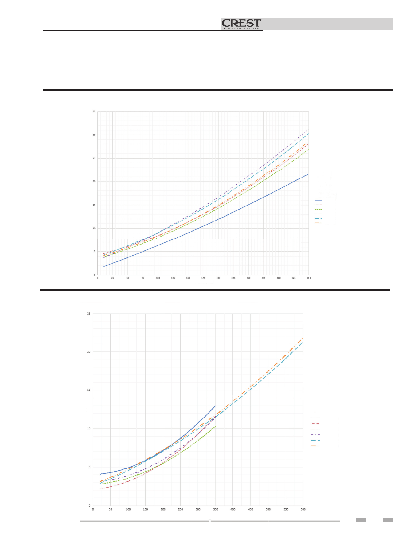
Installation & Operation Manual
5 Hydronic piping
CREST Press Drop Curve
Flow Rate (GPM)
Pressure Drop (Feet of Head)
751
1001
1251
1501
1751
2001
Figure 5-1A Pressure Drop vs. Flow (Models 751 - 2001)
31
Circulator sizing
The Crest heat exchanger does have a pressure drop, which must be considered in your system design. Refer to the graphs in
FIG.’s 5-1A and 5-1B for pressure drop through the Crest heat exchanger.
2501
3001
3501
6001
5001
4001
CREST Press Drop Curve
Flow Rate (GPM)
Pressure Drop (Feet of Head)
Figure 5-1B Pressure Drop vs. Flow (Models 2501 - 6001)
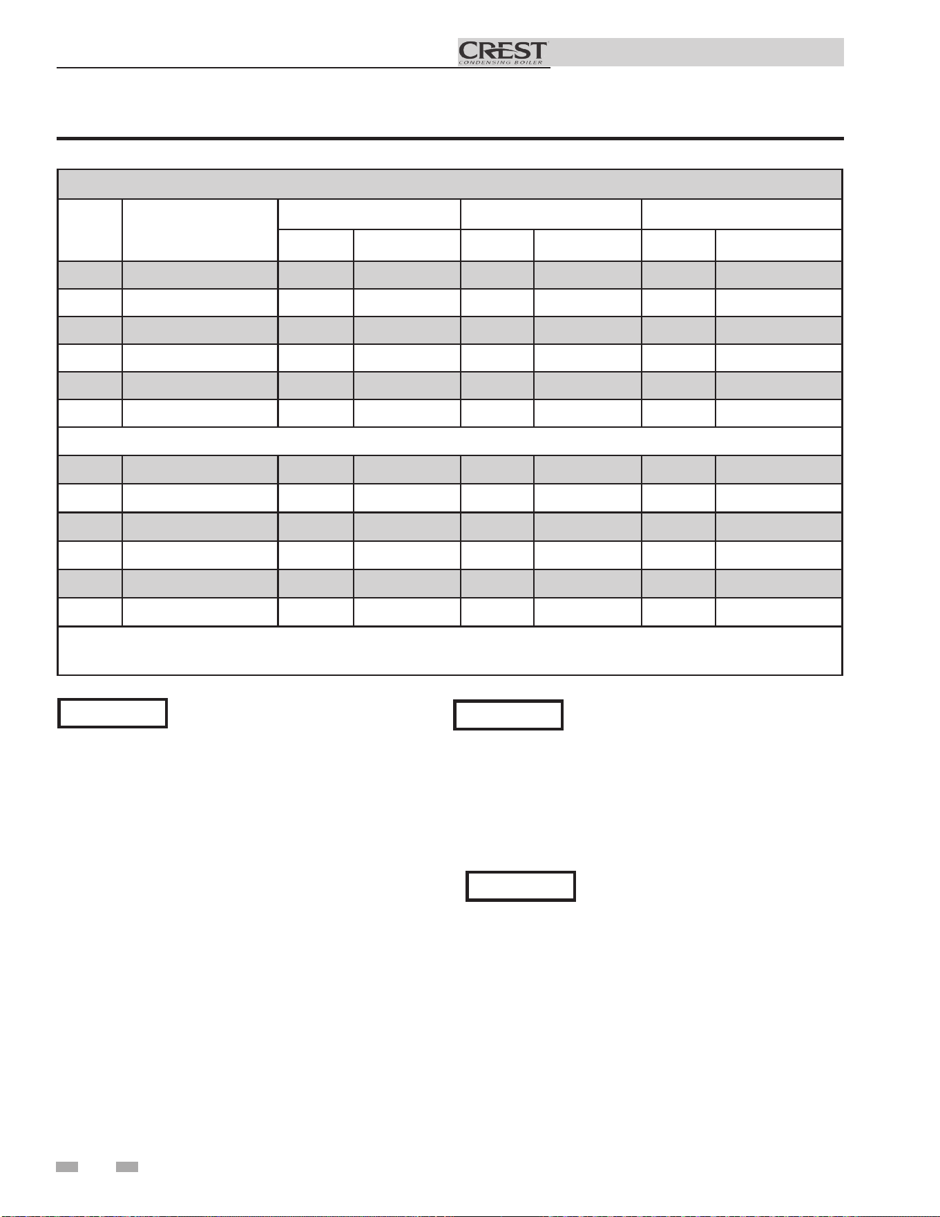
Installation & Operation Manual
5 Hydronic piping (continued)
It is required that boiler piping systems
utilize Primary/Secondary or Fixed or
Variable Flow Primary configurations as
shown in FIG.’s 5-2 thru 5-5. The use of
other boiler piping configurations could
result in improper building and system flow
rates leading to inadvertent boiler high limit
shutdowns and poor system performance.
For fixed or variable flow primary system
configuration, install isolation valves to
prevent flow through unfired boilers in
accordance with ASHRAE 90.1 (6.5.4.3.2).
NOTICE
NOTICE
The pressure drop reflected in FIG. 5-1 is
for the boiler only. Additional allowances
must be made for piping, especially if
sizing pumps for Primary/Secondary
applications.
NOTICE
TEMPERATURE RISE APPLICATIONS
Model
BOILER
CONNECTION SIZE
20°F 40°F 60°F
GPM FT/HD GPM FT/HD GPM FT/HD
FB 0751
3" 72 4.8 36 3.0 24 2.5
FB 1001
3" 96 8.3 48 6.0 32 5.5
FB 1251
3" 120 9.2 60 6.0 40 4.1
FB 1501
4" 144 12.3 72 7.3 48 5.8
FB 1751
4" 168 13.8 84 8.1 56 6.7
FB 2001
4" 192 14.5 96 8.1 64 6.6
FB 2501
4" 240 8.4 120 5.3 80 4.8
FB 3001
4" 288 8.0 144 4.0 96 3.3
FB 3501
4" 336 9.9 168 5.0 112 3.8
FB 4001
4" 350* 10.9 192 5.9 128 4.4
FB 5001
6" 480 13.9 240 7.6 160 5.5
FB 6001
6" 576 17.2 288 9.4 192 6.8
Table 5A Sizing Information for Temperature Rise Applications_20°F, 40°F and 60°F
32
[FB 751 - 2001 models are based on 96% AHRI Eciency]
[Models FB 2501 - 3501 and 6001 based on 96% AHRI Eciency and Models FB 4001 - 5001 based on 96% Eciency]
*Flow is based on 22°F DT.
Installation & Operation Manual
5 Hydronic piping
Near boiler piping components
1. Boiler piping:
Boiler system piping should be sized per the pipe
requirements listed in Tables 5A and 5C.
2. Boiler circulating pump:
Field supplied. When using Primary/Secondary piping the
boiler circulating pump should be sized per Table 5A.
3. Hot Water Generator circulating pump:
Field supplied. When installed in a Primary/Secondary
arrangement, the Crest requires an additional pump for
the Hot Water Generator Loop. The pump should
be sized per Table 5A. Consult the indirect water
heater operating guide to determine flow characteristics
for the selected product used. The pump’s total flow and
heat requirements are the sum of the boiler and the indirect
water heater.
4. Boiler isolation valves:
Field supplied. Full port valves are required. Failure
to use full port valves could result in a restricted flow
rate through the boiler.
5. Check valves:
Field supplied. Check valves are required for
installation as shown in FIG.’s 5-2 and 5-3. Failure to
install check valves could result in a reverse flow
condition during pump(s) off cycle.
6. Domestic indirect hot water isolation valves:
Field supplied. Full port valves are required. Failure to use
full port valves could result in a restricted flow rate through
the boiler.
7. Anti-scald mixing valve:
Field supplied. An anti-scald mixing valve is
recommended when storing domestic hot water above
115°F (46°C).
8. Pressure relief valve:
Factory supplied. The pressure relief valve is sized to
ASME specifications.
9. System temperature sensor:
Lochinvar supplies a system temperature sensor.
The sensor is to be installed in the heating loop
downstream from the boiler hot water piping and
heating loop junction. The sensor should be
located far enough downstream to sense system diluted
water temperature.
10. Water Meter:
Field supplied. A water meter to monitor makeup water is
recommended. Makeup water volume should not exceed
5% of total system per year.
11. Y-Strainer:
Field supplied. Install a Y-strainer or equivalent multi-
purpose strainer just before the boiler pump at the inlet of
the heat exchanger. This item is used to remove system
debris from older hydronic systems and to protect newer
systems.
12. Magnetic Separator:
Field Supplied. Install a magnetic Separator in the heating
system return line as close as practical to the boilker per
the manufacturer’s instructions.
33
⚠ CAUTION
The maximum allowable water flow rate
through a single Crest boiler is 350 GPM for
the 751 - 4001 models and up to 600 GPM
for the 5001 - 6001 models. Exceeding this
flow rate will result in damage to the heat
exchanger and/or piping.
NOTICE
Reference Table 5B for the absolute
minimum flow rate through a single Crest
boiler.
ABSOLUTE MINIMUM FLOW RATE
MODEL FLOW RATE (GPM)
FB(N,L)0751
18
FB(N,L)1001
18
FB(N,L)1251
18
FB(N,L)1501
25
FB(N,L)1751
25
FB(N,L)2001
25
FB(N,L)2501
25
FB(N,L)3001
25
FB(N,L)3501
45
FB(N,L)4001
45
FB(N,L)5001
50
FB(N,L)6001
60
Table 5B Absolute Minimum Flow Rate
NOTICE
A system supply sensor (factory supplied)
MUST BE installed with Primary/Secondary
systems for proper boiler operation.
See the piping illustrations included in this section, FIG.’s 5-2
thru 5-5 for suggested guidelines in piping the Crest.
Please note that these illustrations are meant
to show system piping concept only, the
installer is responsible for all equipment and
detailing required by local codes.
NOTICE
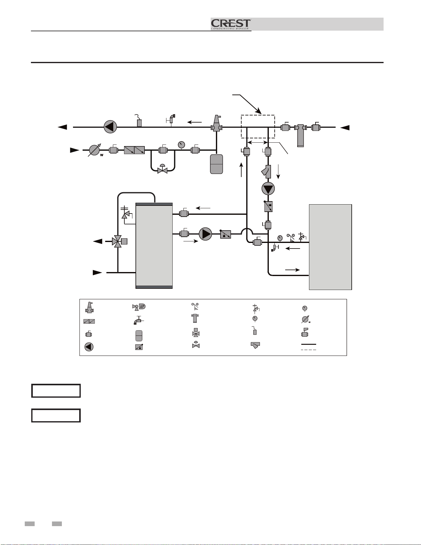
34
Installation & Operation Manual
5 Hydronic piping (continued)
Please note that these illustrations are meant to show piping concepts only, the installer is responsible for all
equipment. The installer must follow all manufacturer’s installation instructions for each system component.
The installer is responsible for compliance with local codes.
NOTICE
Figure 5-2 Single Boiler - Recommended - Primary / Secondary Piping with a Hot Water Generator
System flow should always remain higher than the required flow for the boiler(s) when the boiler(s) is in
operation to prevent short cycling and high limit issues.
NOTICE
2000559501 02
INDIRECT
DHW
TANK
BOILER
T P
MAKE UP
WATER
P
TO
SYSTEM
FROM
SYSTEM
MAY SUBTITUTE
LOW LOSS HEADER
NOT TO EXCEED 4 PIPE DIA OR
MAX OF 12” APART
COLD
WATER IN
DWH HOT
WATER OUT
LEGEND
AIR SEPARATOR
CIRCULATION
PUMP
FLOW CHECK VALVE
PRESSURE GAUGE
P
TEMPERATURE &
PRESSURE GAUGE
T P
SYSTEM SUPPLY
SENSOR
BACKFLOW
PREVENTER
MAGNETIC SEPARATOR
WATER METER
STRAINER / FILTER
PRESSURE
REDUCING VALVE
PRESSURE RELIEF
VALVE
BALL VALVE
EXPANSION TANK
PIPING
DRAIN PORT
DIFFERENTIAL
PRESSURE
BYPASS VALVE
2 WAY MOTORIZED
VALVE (OPTIONAL)
MIXING VALVE
ANTI SCALD
FLOW SWITCH
OPTIONAL
WIRING
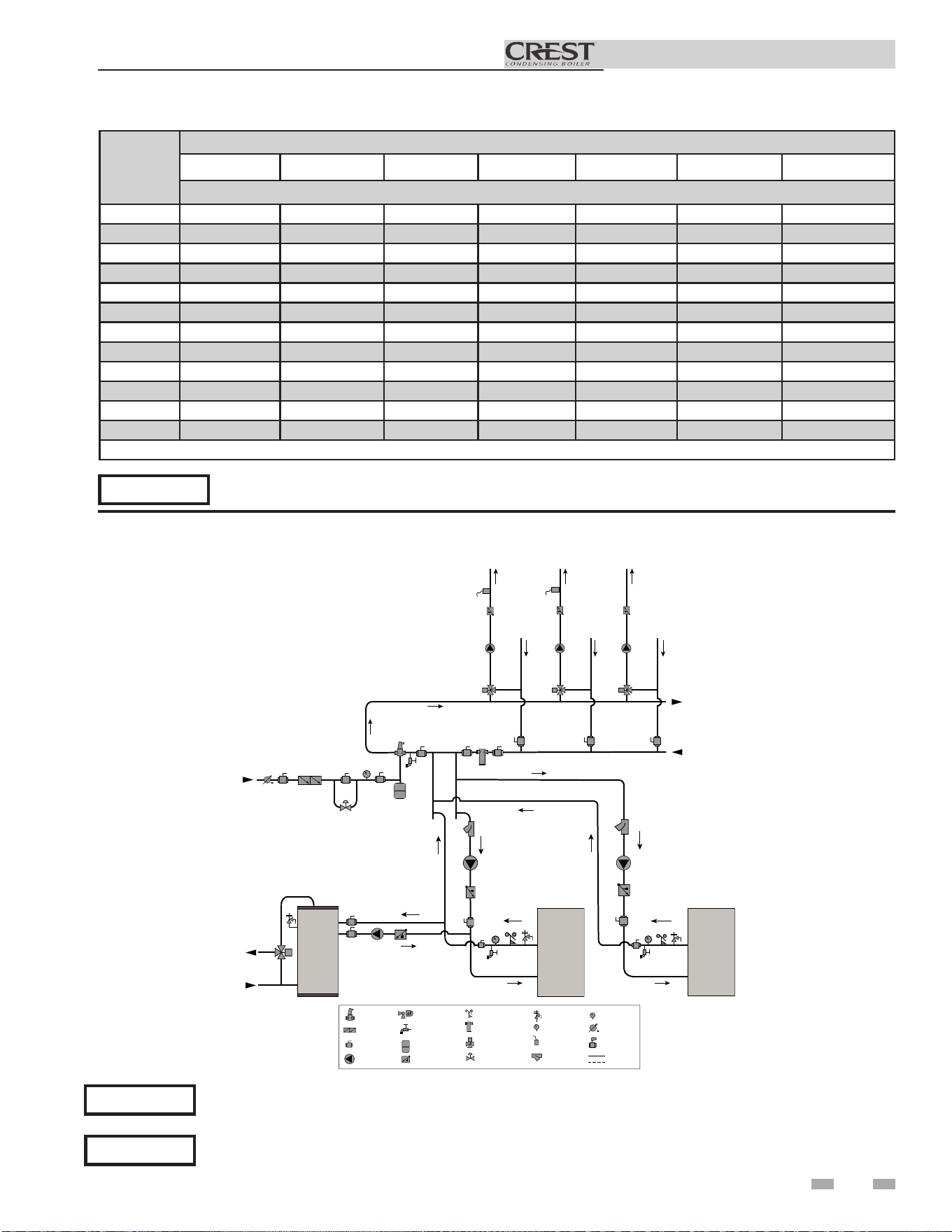
35
Installation & Operation Manual
5 Hydronic piping
Please note that these illustrations are meant to show piping concepts only, the installer is responsible for all
equipment. The installer must follow all manufacturer’s installation instructions for each system component.
The installer is responsible for compliance with local codes.
NOTICE
Figure 5-3 Multiple Boilers - Common Header - Recommended - Primary / Secondary Flow
Model
Number of Units
2 3 4 5 6 7 8
Recommended Common Header Pipe Sizes in Inches
FB 0751
4 4 5 6 6 6 8
FB 1001
4 5 6 6 8 8 8
FB 1251
5 6 8 8 8 8 10
FB 1501
5 6 8 8 8 10 10
FB 1751
5 6 8 8 10 10 10
FB 2001
6 8 8 10 10 10 12
FB 2501
6 8 10 10 12 12 12
FB 3001
8 8 10 12 12 14 14
FB 3501
8 10 10 12 14 14 16
FB 4001
8 10 12 12 14 16 16
FB 5001
10 12 12 14 16 16 18
FB 6001
10 12 14 16 18 18 20
NOTICE
A system supply sensor (factory supplied) MUST BE installed for proper boiler operation.
System flow should always remain higher than the required flow for the boiler(s) when the boiler(s) is in
operation to prevent short cycling and high limit issues.
NOTICE
[Based on a boiler ΔT of 30°F.]
* See page 20 for special instructions when
common venting Crest boilers.
2000809037_03
LEGEND
AIR SEPARATOR
CIRCULATION
PUMP
FLOW CHECK VALVE
PRESSURE GAUGE
P
TEMPERATURE &
PRESSURE GAUGE
T P
SYSTEM SUPPLY
SENSOR
BACKFLOW
PREVENTER
MAGNETIC SEPARATOR
WATER METER
STRAINER / FILTER
PRESSURE
REDUCING VALVE
PRESSURE RELIEF
VALVE
BALL VALVE
EXPANSION TANK
PIPING
DRAIN PORT
DIFFERENTIAL
PRESSURE
BYPASS VALVE
2 WAY MOTORIZED
VALVE (OPTIONAL)
MIXING VALVE
ANTI SCALD
FLOW SWITCH
OPTIONAL
WIRING
TEMP
LOOP 3
TEMP
LOOP 3
TEMP
LOOP 3
TO
SYSTEM
FROM
SYSTEM
SENSOR 1 SENSOR 2 SENSOR 3
PUMP 1 PUMP 2 PUMP 3
VALVE 1 VALVE 2
VALVE 3
P
MAKE UP
WATER
T P
T P
BOILER 2
BOILER 1
INDIRECT
DHW
TANK
DHW HOT
WATER OUT
COLD
WATER IN
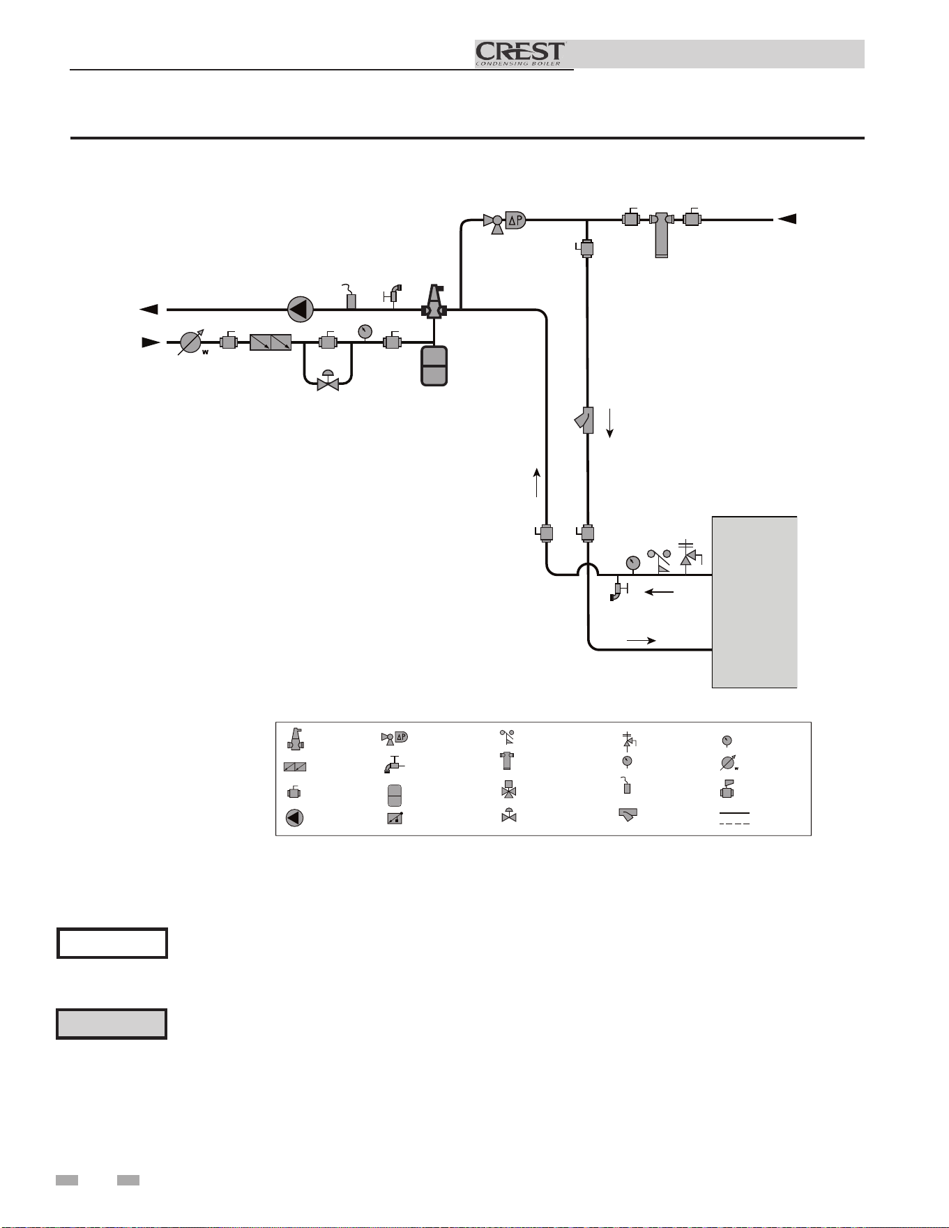
36
Installation & Operation Manual
5 Hydronic piping (continued)
Please note that these illustrations are meant to show piping concepts only, the installer is responsible for all
equipment. The installer must follow all manufacturer’s installation instructions for each system component.
The installer is responsible for compliance with local codes.
NOTICE
Figure 5-4 Single Boiler - Alternate - Fixed or Variable Flow Primary System Piping
2000598465
MAKE UP
WATER
P
TO
SYSTEM
FROM
SYSTEM
LEGEND
AIR SEPARATOR
CIRCULATION
PUMP
FLOW CHECK VALVE
PRESSURE GAUGE
P
TEMPERATURE &
PRESSURE GAUGE
T P
SYSTEM SUPPLY
SENSOR
BACKFLOW
PREVENTER
MAGNETIC SEPARATOR
WATER METER
STRAINER / FILTER
PRESSURE
REDUCING VALVE
PRESSURE RELIEF
VALVE
BALL VALVE
EXPANSION TANK
PIPING
DRAIN PORT
DIFFERENTIAL
PRESSURE
BYPASS VALVE
2 WAY MOTORIZED
VALVE
MIXING VALVE
ANTI SCALD
FLOW SWITCH
OPTIONAL
WIRING
BOILER
T P
⚠ CAUTION
For fixed or variable flow primary system configuration, a differential bypass is recommended (see Figures
5-4 & 5-5). If the differential bypass is excluded, individual boiler flow rates may exceed the maximum flow
allowed, resulting in non-warrantable damage to the heat exchanger, damage to the system piping, and/or
pressure relief valve opening causing excessive make-up water and glycol loss.

37
Installation & Operation Manual
5 Hydronic piping
Please note that these illustrations are meant to show piping concepts only, the installer is responsible for all
equipment. The installer must follow all manufacturer’s installation instructions for each system component.
The installer is responsible for compliance with local codes.
NOTICE
Figure 5-5 Multiple Boilers - Alternate - Common Header - Fixed or Variable Flow Primary
When installing multiple Crest boilers in fixed or variable flow primary applications, utilize a reverse-return or
other piping method to ensure balanced flow through each boiler.
NOTICE
Model
Number of Units
2 3 4 5 6 7 8
Recommended Common Header Pipe Sizes in Inches
FB 0751
4 4 5 6 6 6 8
FB 1001
4 5 6 6 8 8 8
FB 1251
5 6 8 8 8 8 10
FB 1501
5 6 8 8 8 10 10
FB 1751
5 6 8 8 10 10 10
FB 2001
6 8 8 10 10 10 12
FB 2501
6 8 10 10 12 12 12
FB 3001
8 8 10 12 12 14 14
FB 3501
8 10 10 12 14 14 16
FB 4001
8 10 12 12 14 16 16
FB 5001
10 12 12 14 16 16 18
FB 6001
10 12 14 16 18 18 20
[Based on a boiler ΔT of 30°F.]
2000809037_01
BOILER 1
MAKE UP
WATER
P
TO
SYSTEM
FROM
SYSTEM
LEGEND
AIR SEPARATOR
CIRCULATION
PUMP
FLOW CHECK VALVE
PRESSURE GAUGE
P
TEMPERATURE &
PRESSURE GAUGE
T P
SYSTEM SUPPLY
SENSOR
BACKFLOW
PREVENTER
MAGNETIC SEPARATOR
WATER METER
STRAINER / FILTER
PRESSURE
REDUCING VALVE
PRESSURE RELIEF
VALVE
BALL VALVE
EXPANSION TANK
PIPING
DRAIN PORT
DIFFERENTIAL
PRESSURE
BYPASS VALVE
2 WAY MOTORIZED
VALVE
MIXING VALVE
ANTI SCALD
FLOW SWITCH
OPTIONAL
WIRING
BOILER 2
T P
T P
⚠ CAUTION
For fixed or variable flow primary system configuration, a differential bypass is recommended (see Figures 5-4 &
5-5). If the differential bypass is excluded, individual boiler flow rates may exceed the maximum flow allowed,
resulting in non-warrantable damage to the heat exchanger, damage to the system piping, and/or pressure relief
valve opening causing excessive make-up water and glycol loss.
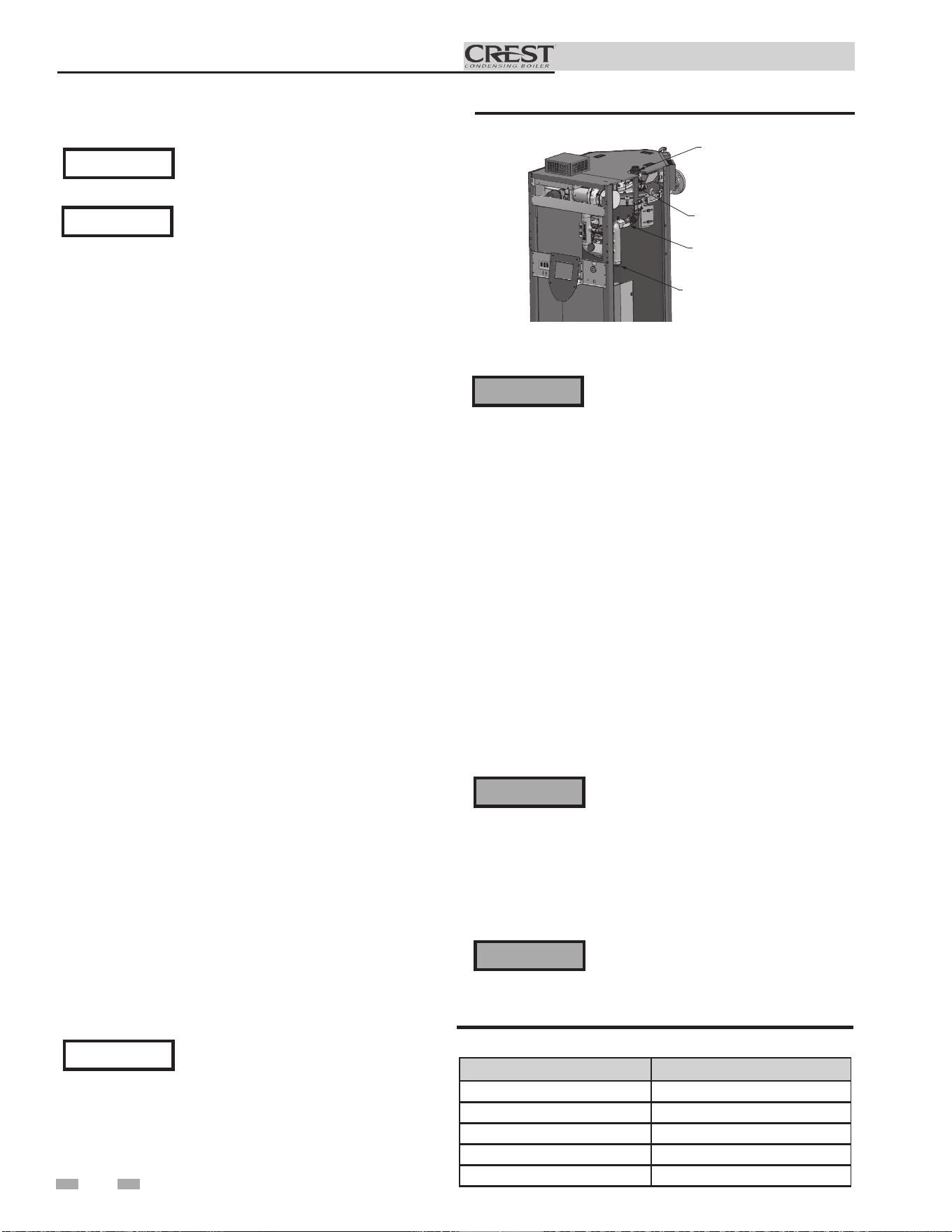
38
Installation & Operation Manual
6 Gas connections
Connecting gas supply piping
1. Refer to FIG. 6-1 to pipe gas to the boiler.
a. Install ground joint union for servicing, when
required.
b. In Canada – When using manual main shutoff
valves, it must be identified by the installer.
Do not check for gas leaks with an open
flame – use the bubble test. Failure to
use the bubble test or check for gas leaks
can cause severe personal injury, death, or
substantial property damage.
3. Purge all air from the gas supply piping.
4. Before placing the boiler in operation, check the boiler
and its gas connection for leaks.
a. The appliance must be disconnected from the gas
supply piping system during any pressure testing of
that system at a test pressure in excess of 1/2 PSIG
(3.5 kPa).
b. The appliance must be isolated from the gas supply
piping system by closing a manual shutoff valve
during any pressure testing of the gas supply piping
system at test pressures equal to or less than 1/2 PSIG
(3.5 kPa).
c. The appliance and its gas connection must be leak
tested before placing it in operation.
⚠WARNING
5. Use pipe sealing compound compatible with propane
gases. Apply sparingly only to male threads of the pipe
joints so that pipe dope does not block gas flow.
Failure to apply pipe sealing compound as
detailed in this manual can result in severe
personal injury, death, or substantial
property damage.
⚠WARNING
Model Gas Inlet Size
FB0751 - FB1001 1 1/4"
FB1251 - FB2001 1 1/2"
FB2501 - FB3501 2"
FB4001 - FB5001 2 1/2"
FB6001 3"
Table 6A Gas Inlet Size
For dual fuel models, reference the Crest
Dual Fuel Supplemental Manual.
NOTICE
Gas supply
1. It is recommended to install one (1) gas regulator for each
Crest boiler.
2. Gas regulators should be installed in a horizontal
orientation unless otherwise recommended by the
regulator manufacturer.
3. It is recommended to install a filter at the inlet of a gas
regulator to prevent debris from entering the regulator.
4. Gas regulators should be installed the greater of either 20
inches or 10 pipe diameters from the nearest fitting, elbow,
or valve to the outlet of the regulator.
5. It is recommended that the gas regulator outlet size match
the gas inlet size of the boiler and to not change the pipe
size between them. If the pipe diameter must be increased,
a bell reducer type fitting should be located at the regulator
outlet and the boiler inlet, maintaining the distance
indicated in Step 4.
6. Gas regulators must be properly vented to ensure proper
function:
a. Vent pipe must be no smaller than the regulator vent
connection size.
b. Each regulator must have a separate vent line.
c. Vent lines must not be combined together or with any
other equipment that also requires atmospheric vents.
d. Excessive gas regulator vent length will detrimentally
affect regulator performance:
• Gas regulators must be properly vented according to
the regulator manufacturer’s instructions.
• It is recommended that regulator vent length not
exceed 15 equivalent feet (4.5 m).
• When regulator vent must exceed 15 equivalent feet, it
is recommended to use a ventless regulator equipped
with a vent limiter.
• If a ventless regulator cannot be utilized, it is
recommended to increase vent diameter by one pipe
size after the initial 15 equivalent feet and every additional
10 equivalent feet.
e. Proper measures must be taken to prevent water,
snow, insects, or other debris from obstructing the vent.
Ensure that the high gas pressure regulator
is at least 10 feet (3 m) upstream of the
appliance.
NOTICE
2. Support piping with hangers, not by the boiler or its
accessories.
The gas valve and blower will not support
the weight of the piping. Do not attempt
to support the weight of the piping with
the boiler or its accessories. Failure to
comply could result in severe personal
injury, death, or substantial property
damage.
⚠WARNING
Figure 6-1 Gas Supply Piping
IMG01131
SEDIMENT TRAP/
DRIP LEG CLEAN OUT
(FACTORY SUPPLIED)
MANUAL SHUTOFF
VALVE
(FACTORY SUPPLIED)
GAS SUPPLY
UNION
(FACTORY
SUPPLIED)
The gas inlet size has been designed to
allow the minimum of 10 feet between the
boiler and regulator and for a maximum
pressure drop of 1" w.c.
NOTICE
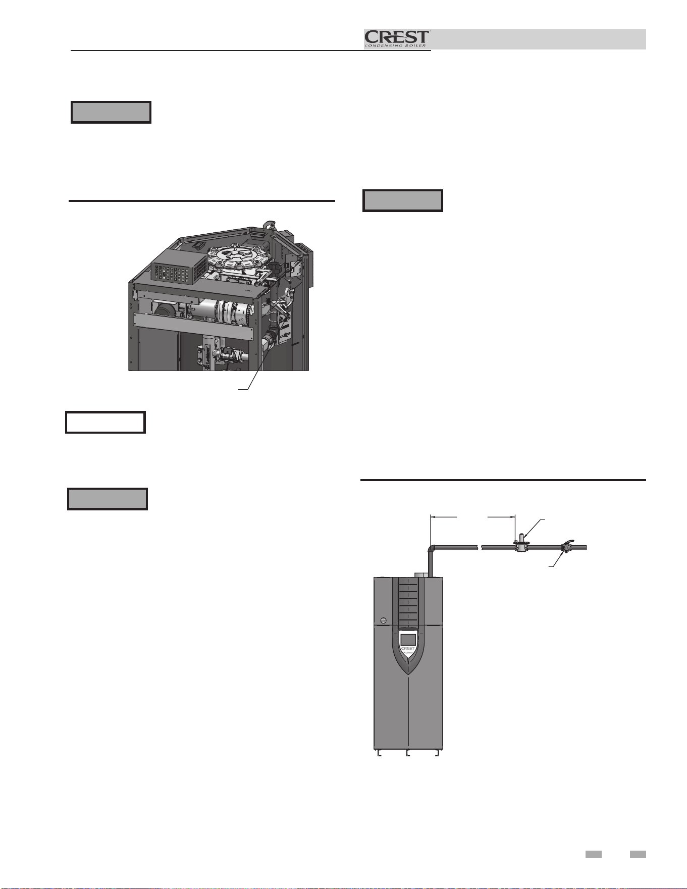
Installation & Operation Manual
6 Gas connections
Use two wrenches when tightening gas
piping at boiler (FIG. 6-2), using one
wrench to prevent the boiler gas line
connection from turning. Failure to
support the boiler gas connection pipe
to prevent it from turning could damage
gas line components.
IMG01132
USE BACK UP WRENCH TO PREVENT
PIPE FROM ROTATING
Figure 6-2 Inlet Pipe with Backup Wrench
3. Install 100% lockup gas pressure regulator in supply line for
each boiler if inlet pressure exceeds 14 inches w.c. (3.5 kPa).
4. Gas valves used on Crest boilers are rated for at least 27
inches w.c. (6.7 kPa).
Propane Gas:
Pipe sizing for propane gas
1. Contact gas supplier to size pipes, tanks, and 100% lockup
gas pressure regulator.
Propane Supply Pressure Requirements
1. Target a supply pressure of 11 inches w.c. (2.7 kPa) measured
when the boiler is operating at minimum input rate. Gas
pressure can be adjusted higher or lower than 11 inches w.c.
as needed.
2. Adjust propane supply regulator provided by the gas
supplier for 14 inches w.c. (3.5 kPa) maximum pressure.
3. Pressure required at gas valve inlet pressure port:
• Maximum 14 inches w.c. (3.5 kPa) with boiler operating.
• Minimum 8 inches w.c. (1.99 kPa) with boiler operating.
Maximum inlet gas pressure must not
exceed the value specified. Minimum
value listed is for the purposes of input
adjustment.
⚠WARNING
⚠WARNING
NOTICE
Check boiler rating plate to determine which
fuel the boiler is set for. Crest boilers CAN
NOT be field converted. Failure to comply
could result in severe personal injury, death,
or substantial property damage.
⚠WARNING
Check boiler rating plate to determine
which fuel the boiler is set for. Crest
boilers CANNOT be field converted.
Failure to comply could result in severe
personal injury, death, or substantial
property damage.
Natural gas:
Pipe sizing for natural gas
1. Refer to Table 6B for pipe length and diameter. Based on
rated boiler input (divide by 1,000 to obtain cubic feet per
hour).
a. Table 6B is only for natural gas with specific gravity
0.60, with a pressure drop through the gas
piping of 0.3 inches w.c.
b. For additional gas pipe sizing information, refer to
the National Fuel Gas Code, NFPA 54 / ANSI Z223.1
- latest edition, or in Canada CSA B149.1 Installation
Code.
Natural gas supply pressure requirements
1. Target a supply pressure of 7 inches w.c. (1.7 kPa)
measured when the boiler is operating at minimum input
rate. Gas pressure can be adjusted higher or lower than 7
inches w.c. as needed.
2. Pressure required at the gas valve inlet pressure port:
• Maximum 14 inches w.c. (3.5 kPa) with boiler operating.
• Minimum 4 inches w.c. (.99 kPa) with boiler operating.
GAS PRESSURE
REGULATOR
(FIELD SUPPLIED)
10'
MINIMUM
*MANUAL SHUT
OFF VALVE
(FIELD SUPPLIED)
*IN COMPLIANCE WITH
248 CMR7.04(9)(f), PROVISIONS
SHALL BE MADE SO THE GAS
SUPPLY TO THE BOILER(S) MAY
BE SHUT OFF FROM A LOCATION
OUTSIDE THE BOILER ROOM.
IMG01040
Figure 6-3 Gas Supply Piping to Regulator
39
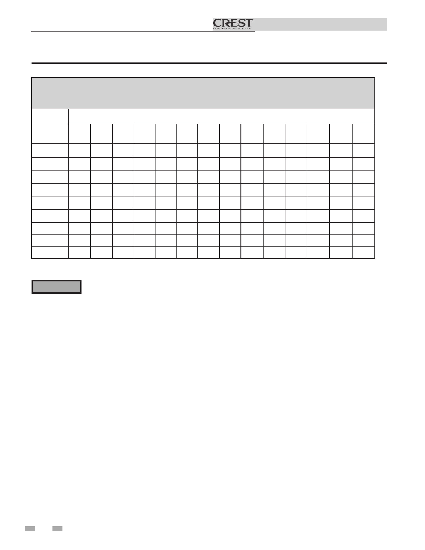
40
Table 6B Natural Gas Pipe Size Chart
DO NOT adjust or attempt to measure gas
valve outlet pressure. Attempting to alter
or measure the gas valve outlet pressure
could result in damage to the valve, causing
potential severe personal injury, death, or
substantial property damage.
⚠WARNING
Check inlet gas supply
6 Gas connections (continued)
Installation & Operation Manual
TABLE - 6B
Capacity of Schedule 40 Metallic Pipe in Cubic Feet of Natural Gas Per Hour
(based on .60 specific gravity, 0.30" w.c. pressure drop)
Pipe
Size
(Inches)
Length of Pipe in Straight Feet
10 20 30 40 50 60 70 80 90 100 125 150 175 200
1/2 131 90 72 62 55 N/A N/A N/A N/A N/A N/A N/A N/A N/A
3/4 273 188 151 129 114 104 95 89 83 79 70 63 58 N/A
1 514 353 284 243 215 195 179 167 157 148 131 119 109 102
1 1/4 1,060 726 583 499 442 400 368 343 322 304 269 244 224 209
1 1/2 1,580 1,090 873 747 662 600 552 514 482 455 403 366 336 313
2 3,050 2,090 1,680 1,440 1,280 1,160 1,060 989 928 877 777 704 648 602
2 1/2 4,860 3,340 2,680 2,290 2,030 1,840 1,690 1,580 1,480 1,400 1,240 1,120 1,030 960
3 8,580 5,900 4,740 4,050 3,590 3,260 3,000 2,790 2,610 2,470 2,190 1,980 1,820 1,700
4 17,500 12,000 9,660 8,270 7,330 6,640 6,110 5,680 5,330 5,040 4,460 4,050 3,720 3,460
The gas piping must be sized for the proper flow and length of
pipe, to avoid excessive pressure drop. Both the gas meter and
the gas regulator must be properly sized for the total gas load.
If gas pressure drops more than 1 inch w.c. (249 Pa) between
maximum and minimum input rate, the meter, regulator, or
gas line may be undersized or in need of service. Perform the
steps below when checking inlet gas supply:
1. Turn the main power switch to the “OFF” position.
2. Shut off gas supply at the manual gas valve in the gas
piping to the appliance.
3. For Crest models (751-2001): Remove the 1/8” pipe plug
on the gas manifold before the gas valve, and install a
suitable 1/8” fitting (field supplied) for the manometer
tubing. Place the tubing of the manometer over the tap
once the 1/8” fitting is installed as shown in FIG. 6-4.
For Crest models (2501-6001): Remove the 1/8” pipe plug
on the large gas valve flange before the gas valve, and install a
suitable 1/8” fitting (field supplied) for the manometer tubing.
Place the tubing of the manometer over the tap once the
1/8”fitting is installed as shown in FIG. 6-4.
4. Slowly turn on the gas supply at the factory installed
manual gas valve.
5. Turn the power switch to the “ON” position.
6. Adjust the temperature set point on the control panel of
the SMART TOUCH control module to call for heat or
utilize Service Mode, see page 51 of this manual.
7. Observe the gas pressure with the burner
operating at 100% of rated input. Without turning
off the boiler, reduce the burner to the minimum input
rate and observe the gas pressure with the burner at
the minimum input rate. Percent of burner input will be
displayed on the Modulation Screen.
8. Ensure inlet pressure is within specified range.
Minimum and maximum gas supply pressures are
specified in this section of the manual.
9. If gas supply pressure is within normal range and no
adjustments are needed, proceed on to Step 11.
10. If the gas pressure is out of range, contact the gas utility,
gas supplier, qualified installer or service agency to
determine the necessary steps to provide proper gas
pressure to the control.
11. Turn the power switch to the “OFF” position.
12. Shut off the gas supply at the manual gas valve in the gas
piping to the appliance.
13. Remove the manometer from the pressure tap on the
gas manifold or gas valve flange, depending on model
size. Remove the 1/8” (3 mm) field supplied fitting and
reinstall the pipe plug removed in Step 3.
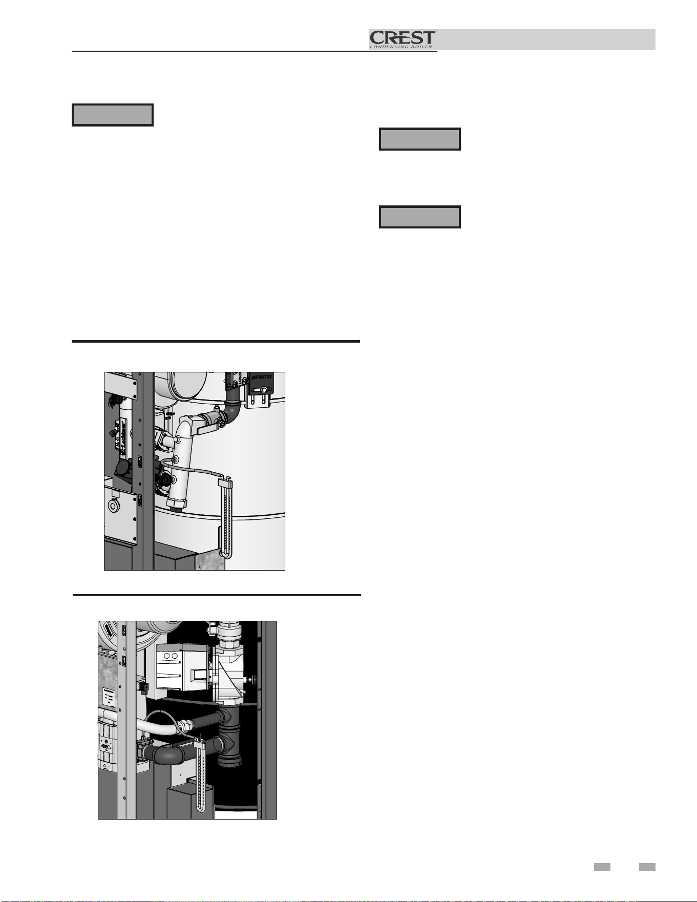
41
Installation & Operation Manual
⚠WARNING
Do not check for gas leaks with an open
flame -- use the bubble test. Failure to
use the bubble test or check for gas leaks
can cause severe personal injury, death, or
substantial property damage.
14. Turn on the gas supply at the manual gas valve.
15. Turn the power switch to the “ON” position.
16. Adjust the temperature set point on the control panel of
the SMART TOUCH control module to the desired
water temperature so the appliance will call for heat.
17. Check burner performance by cycling the system while
you observe burner response. The burner should ignite
promptly. Flame pattern should be stable. Turn system
off and allow burner to cool, then cycle burner again to
ensure proper ignition and flame characteristics.
Gas valve replacement
Figure 6-4A Inlet Gas Supply Check - model 751-2001
DO NOT adjust or attempt to measure
gas valve outlet pressure. Attempting
to alter or measure the gas valve outlet
pressure could result in damage to the
valve, causing potential severe personal
injury, death, or substantial property
damage.
The gas valve MUST NOT be replaced
with a conventional gas valve under
any circumstances. Failure to follow all
precautions could result in fire, explosion,
or death!
⚠WARNING
⚠WARNING
6 Gas connections
2000610998 00
Figure 6-4B Inlet Gas Supply Check - model 2501-6001
2000610959 00
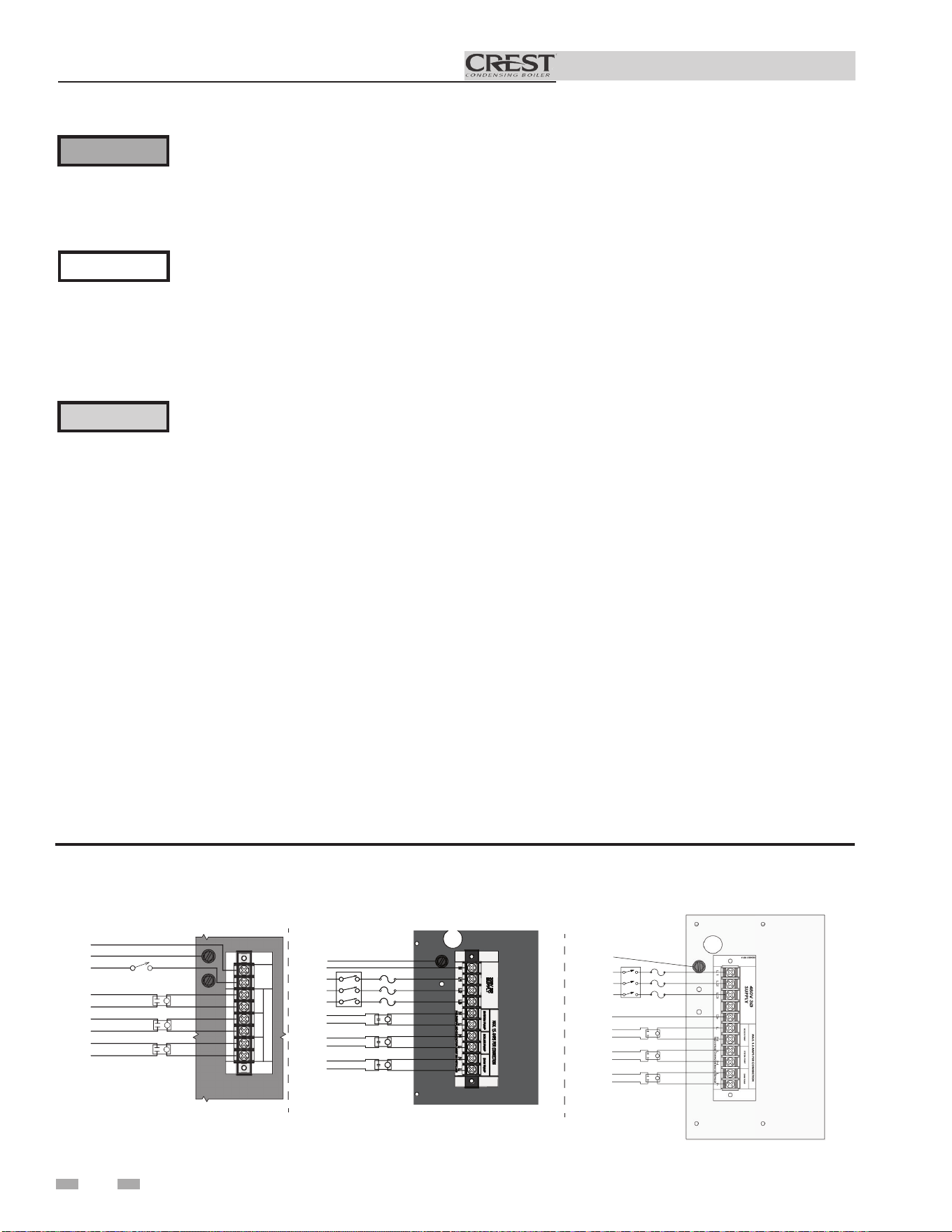
Installation & Operation Manual
7 Field wiring
ELECTRICAL SHOCK HAZARD – For
your safety, turn off electrical power supply
before making any electrical connections
to avoid possible electric shock hazard.
Failure to do so can cause severe personal
injury or death.
Wiring must be N.E.C. Class 1.
If original wiring as supplied with boiler
must be replaced, use only type 105°C
wire or equivalent.
Boiler must be electrically grounded as
required by National Electrical Code
ANSI/NFPA 70 – latest edition.
Installation must comply with:
1. National Electrical Code and any other national, state,
provincial, or local codes, or regulations.
2. In Canada, CSA C22.1 Canadian Electrical Code Part 1,
and any local codes.
Line voltage connections - Models
751 - 2001, 120 VAC, 1PH
1. Connect 120 VAC 1PH power wiring to the line voltage
terminal strip in the junction box, as shown in FIG. 7-1.
2. Provide and install a fused disconnect or service switch
sized per the boiler amp draw (shown on the boiler rating
plate) as required by the code (see FIG. 7-1).
3. When connecting the boiler, system and hot water
generator pumps connect the wiring to the line voltage
terminal strip as shown in FIG. 7-1. Maximum current
is 1.5 amps. Install a field supplied contactor between the
pump(s) and the boiler connections.
4. For alternate voltages, consult factory.
Figure 7-1 Boiler Line Voltage Field Wiring Connections
Label all wires prior to disconnection when
servicing controls. Wiring errors can
cause improper and dangerous operation.
⚠WARNING
NOTICE
⚠ CAUTION
Line voltage connections - Models
2501 - 3501 208 VAC 3PH / 4001 -
6001 480 VAC 3PH
1. Connect 208 / 480 VAC 3PH Wye power wiring to the line
voltage terminal strip in the junction box, as shown in FIG.
7-1.
2. Provide and install a fused disconnect or service switch
sized per the boiler amp draw (shown on the boiler rating
plate) as required by the code (see FIG. 7-1).
3. When connecting the boiler, system and hot water generator
pumps connect the wiring to the line voltage terminal strip
as shown in FIG. 7-1. Maximum current is 1.5 amps. Install
a field supplied contactor between the pump(s) and the
boiler connections.
4. For alternate voltages, consult factory.
120V
SUPPLY
SYSTEM PUMP
BOILER
PUMP
HWGPUMP
MAX. 1.5 AMPSPER
CON
NECTION
NL
FIELDSUPPLIED CON
TACTOR
MUST
BE INSTAL
LED
GROUND G
NEUTRAL W
LINE BK
SYSTEM PUMP
DR
YCONTACT
BOILER PUMP
DR
YCONTACT
HWGPUMP
DR
YCONTACT
SERVICE SWITCH
CONTACTOR
(FIELD SUPPLIED)
MODELS 751 - 2001: 120 V
NEUTRAL W
SERVICESWITCH
CONTACTOR
(FIELD SUPPLIED)
L1 BK
L2 R
L3 BL
BOILER PUMP
DRYCONTACT
SYSTEM PUMP
DRYCONTACT
DHWPUMP
DRYCONTACT
IMG00319
GROUND G
MODELS 2501 - 3501: 208 V
GROUND G
SERVICE SWITCH
L3 BL
L2 R
DRY CONTACT
BOILER PUMP
DRY CONTACT
DHW PUMP
DRY CONTACT
SYSTEM PUMP
L1 BK
CONTACTOR
GROUND G
DIR #2000601620 00
-
MODELS 4001 - 6001: 480 V
42
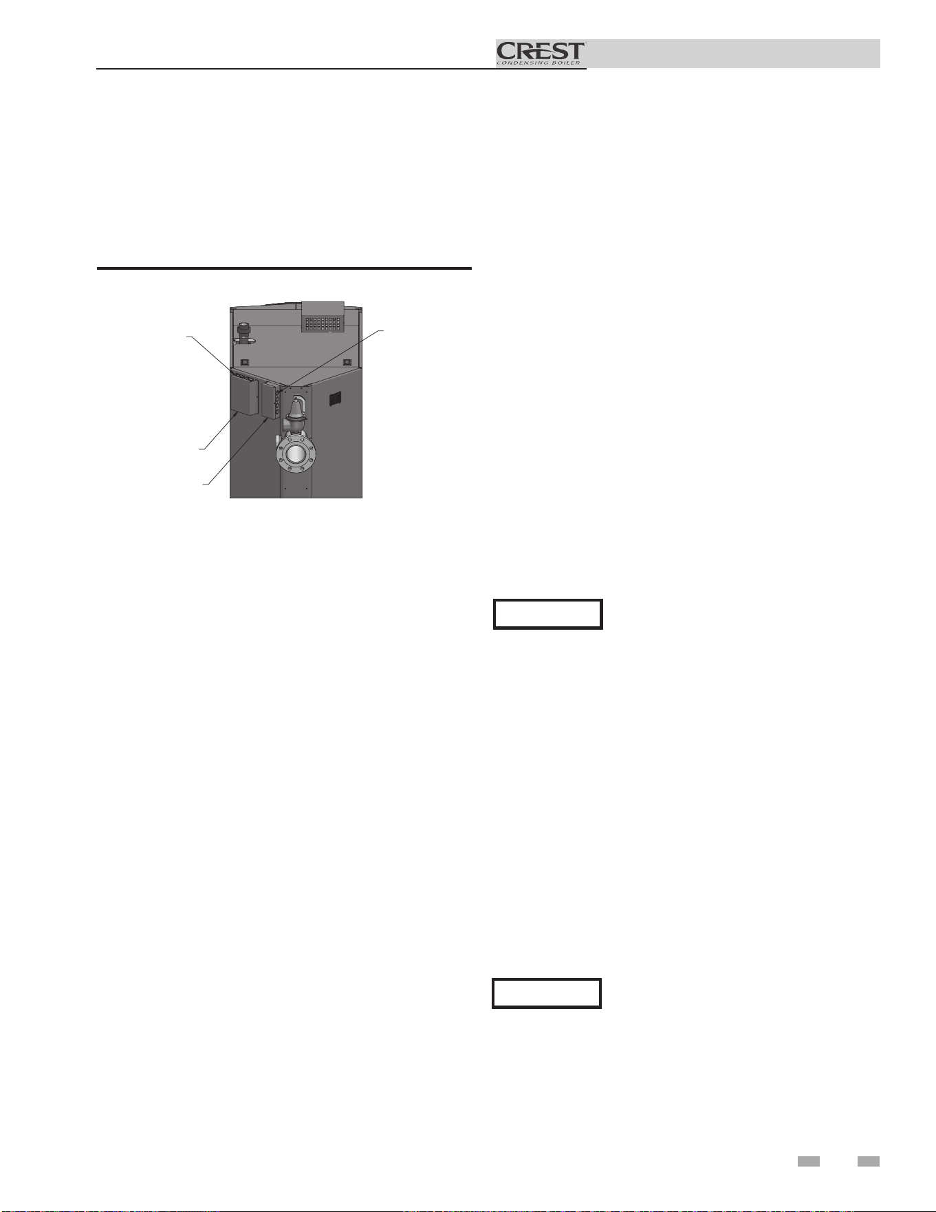
Installation & Operation Manual
Low voltage connections
1. Route all low voltage wires through the knockouts in the
rear of the boiler, as shown in FIG. 7-2.
2. Connect low voltage wiring to low voltage connection
board as shown in FIG. 7-3 on page 44 of this manual and
the boiler wiring diagram.
IMG01041
LOW VOLTAGE
WIRING KNOCKOUTS
LINE VOLTAGE
WIRING KNOCKOUTS
LINE VOLTAGE
J-BOX
LOW VOLTAGE
J-BOX
Figure 7-2 Routing Field Wiring
7 Field wiring
Enable
1. Connect the room thermostat or boiler enable contacts
(isolated contact only) to terminals 7 and 8, as shown in
FIG. 7-3.
2. If a thermostat is used, install the thermostat on the inside
wall away from influences of drafts, hot or cold water
pipes, lighting fixtures, television, sunlight, or fireplaces.
3. Thermostat anticipator (if applicable):
a. If connected directly to boiler, set for 0.1 amps.
b. If connected to relays or other devices, set to match
total electrical power requirements of connected
devices. See device manufacturers’ specifications
and thermostat instructions for details.
Outdoor temperature sensor
1. Connect the outdoor temperature sensor (FIG. 7-3) to
the Outdoor Sensor terminals on the connection board to
enable outdoor reset operation of the Crest.
2. Mount the sensor on an exterior wall, shielded from direct
sunlight or flow of heat or cooling from other sources.
3. Route sensor wires through a knockout at the rear of the
boiler (see FIG. 7-2).
Variable speed system pump
If a variable speed pump is used in the primary loop, and
a 0-10V signal is available from the pump speed control,
this signal can be used by the SMART TOUCH control to
anticipate changes in the building heat load. By connecting
this 0 - 10V signal to the 0 - 10V SYS PUMP IN terminals, the
boiler (or cascade) can modulate up and down as the primary
flow increases and decreases.
ModBus / BACnet
The RS-485 ModBus / BACnet cable is connected to the
ModBus terminals. Use shielded, 2-wire twisted pair cable. If
desired, the shield can be connected to ground by installing a
jumper wire between terminals 1 and 3 on connector X5 on the
ModBus interface module.
Hot Water Generator (HW)
thermostat
1. Connect the HW tank thermostat to the Tank Thermostat
terminals on the connection board (FIG. 7-3).
Hot Water Generator (HW) tank
sensor
1. By installing a HW tank sensor, the SMART TOUCH
control can perform the tank thermostat function. The
SMART TOUCH control automatically detects the presence
of this sensor, and generates a HW call for heat when the
tank temperature drops 6°F (3°C) below the tank set point,
and finishes the call for heat when the tank temperature
reaches the tank set point.
2. A #100170544 sensor MUST be used with any indirect
tank. Failure to use the correct sensor will result in the
tank temperature being either above or below the set point.
Connect the correct sensor to the Tank Sensor terminals
(see FIG. 7-3).
Louver relay
If louvers need to operate before the boiler fires, they can be
controlled by this output. Connect these terminals to a 24V
relay coil, which is wired to operate the louvers (FIG. 7-3).
Louver proving switch
Louvers are used to provide combustion air for the room air
option. A louver proving switch should be connected to the
appropriate terminals and are verified prior to operation (see
FIG. 7-3).
Boiler pump speed output
This 0 - 10V output is available to control the speed of a variable
speed boiler pump. The SMART TOUCH control will vary the
speed of this pump in order to maintain a minimum DT (set
by the installer, see the Crest Service Manual) across the heat
exchanger, as well as prevent high limit lockouts when the flow
in the primary loop is extremely low. Connect this output to the
0 - 10V input on the boiler pump speed control.
Rate output
This output provides a 0 - 10V signal that is proportional to the
firing rate of the boiler. This may be used by a BMS system to
monitor the actual rate of the boiler.
43
NOTICE
The system supply temperature must be
provided for this feature to work. The
temperature can be sensed directly with
a system supply sensor, or sent through
ModBus/BACnet. This feature is to be used
with primary /secondary piping systems.
NOTICE
See page 20 for special instructions when
common venting Crest boilers.
44
Installation & Operation Manual
7 Field wiring (continued)
Auxiliary switch 1 & 2
Additional field supplied limit controls may be connected to
the auxiliary switch inputs. If additional limit controls fail or
open, it will result in a manual reset lockout.
System supply sensor
1. By installing the system supply sensor into the supply
of the primary loop, the temperature of the system
supply can be controlled. The SMART TOUCH control
automatically detects the presence of this sensor, and
controls the boiler firing rate to maintain the system
supply temperature to the set point.
2. For system supply sensor wiring information reference
(FIG. 7-3).
Boiler management system
1. An external control may be connected to control either
the firing rate or the set point of the boiler. Connect the
0 - 10 VDC terminals to the 0 - 10 VDC output of the
external control. The SMART TOUCH control can be
enabled using the Enable output (see page 44) or using
the voltage applied to the 0 - 10 VDC input. Reference
the Crest Service Manual for more details.
2. Make sure terminal #34 on the Low Voltage Connection
Board is connected to the (-) or COM output terminal
of the external control, and 0 - 10 VDC terminal #33 is
connected to the 0 - 10 VDC terminal of the external
control.
Runtime contacts
The SMART TOUCH control closes a set of dry contacts
whenever the burner is running. This is typically used by
Building Management Systems to verify that the boiler is
responding to a call for heat.
Alarm contacts
The SMART TOUCH control closes another set of contacts
whenever the boiler is locked out or the power is turned off.
This can be used to turn on an alarm, or signal a Building
Management System that the boiler is down.
System return sensor
1. Install the system return sensor into the return of the
primary loop.
2. Connect the terminals to the system return sensor as
shown in FIG. 7-3.
Wiring of the cascade
When wiring the boilers for Cascade operation, select one boiler
as the Leader boiler. The remaining boilers will be designated
as Members. See page 54 “Configuration of the Cascade” for a
detailed explanation of this procedure.
Connect the system supply sensor and outdoor air sensor (if
used) to the Leader boiler. For the Cascade system to work
properly the system supply sensor must be installed. The
location of the system supply sensor should be downstream
of the boiler connections in the main system loop (FIG.’s 5-2
through 5-5). The system supply sensor should be wired to the
Low Voltage Connection Board at the terminals marked for the
system sensor (see FIG. 7-3). The Leader control will use the
water temperature at the system supply sensor to control the
operation of the Cascade.
If outdoor air reset is desired, the outdoor air sensor should be
wired to the Low Voltage Connection Board at the terminals
marked for the outdoor air sensor (FIG. 7-3). If the outdoor
air sensor is connected, the Leader control will calculate the
water temperature set point based on the programmed reset
curve parameters. If the outdoor air sensor is not connected,
the Leader control will maintain the fixed water temperature set
point that is programmed into the control.
If a Thermostat or Zone Control Enable output is available, it
should be wired to the Low Voltage Connection Board on the
Leader boiler at the terminals marked Enable (FIG. 7-3). If the
boilers are to run continuously, connect a jumper wire between
the R and W terminals for the Enable input. This will initiate a
call for heat on the Cascade.
Communication between the Leader boiler and the Member
boilers is accomplished by using shielded, 2-wire twisted pair
communication cable. Connect one of the twisted pair wires
to Cascade terminal A on each of the Low Voltage Connection
boards, and the other wire of the twisted pair to Cascade
terminal B on each of the Low Voltage Connection Boards.
Connect the shield wires to one of the shield terminals on
the Low Voltage Connection Boards (FIG. 7-3). If more than
two boilers are on the Cascade, daisy chain the wiring from
the Cascade terminals on the second boiler to the Cascade
terminals on the third boiler, then from the third to the forth,
and so on. The connections between boilers can be made in any
order, regardless of the addresses of the boilers. Try to keep
each cable as short as possible.
When the Member 1 boiler is programmed as an alternate
leader this allows the Member 1 boiler to automatically assume
control of the Cascade should it lose communication with the
Leader boiler. When programmed to YES, it is recommended
that the Member 1 boiler have its own set of external sensors
installed (such as the system supply sensor), to maintain the
same level of temperature control as with the Leader boiler.
Voltage signals (such as 0 - 10V system pump speed input) can
be connected to both boilers.
NOTICE
Unless a firing rate is being provided by
a BMS system, a system supply sensor
(factory supplied) MUST BE installed
with Primary/Secondary piping systems
for proper boiler operation.
NOTICE
DO NOT INSTALL THE SYSTEM
SUPPLY SENSOR INTO THE SYSTEM
RETURN.
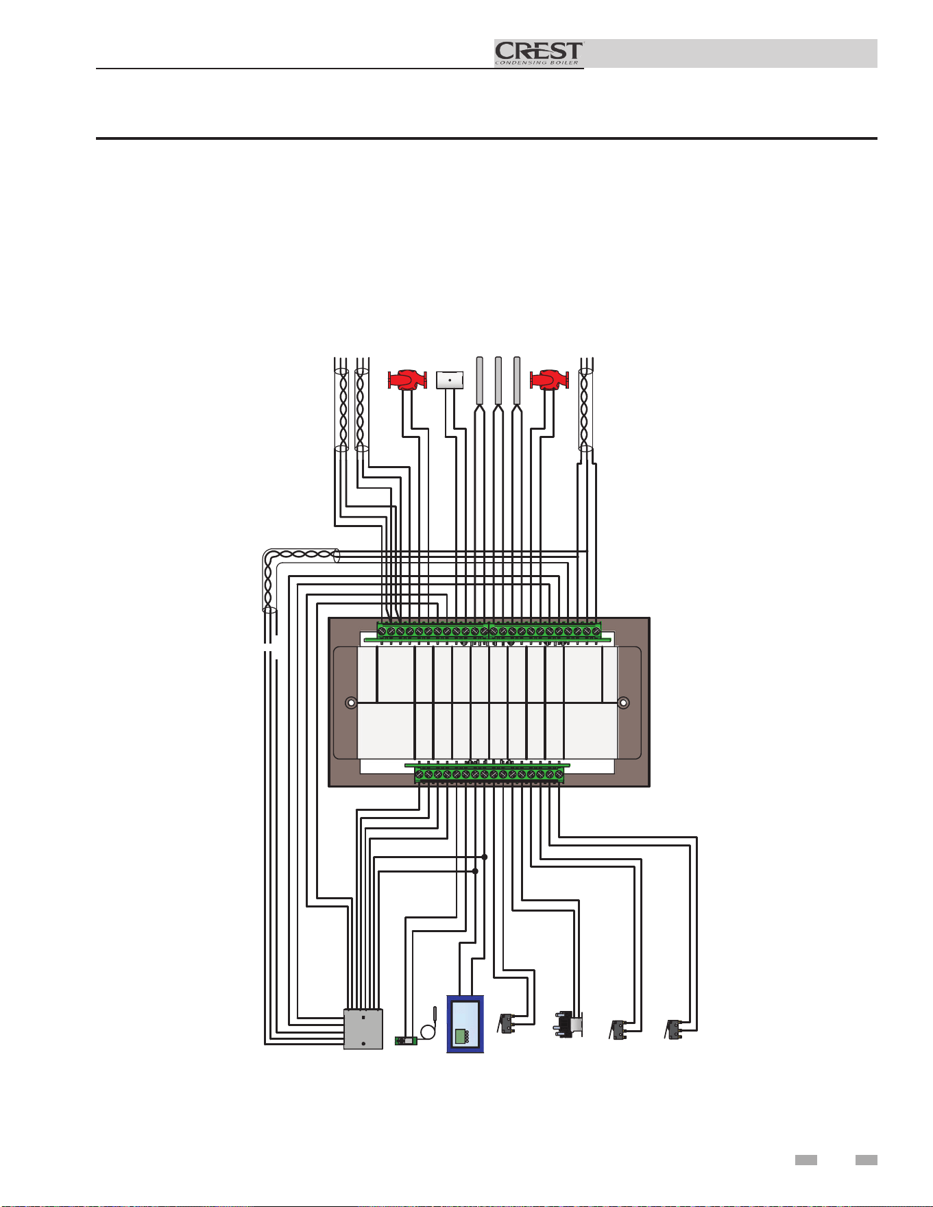
45
Installation & Operation Manual
7 Field wiring
1
2
3
4
5
6
7
8
9
10
11
12
13
14
15
16
ALARM
CONTACTS
RUN TIME
CONTACTS
TANK
THERMOSTAT
ENABLE
LOUVER
PROVING
LOUVER
RELAY
AUX
SWITCH 1
AUX
SWITCH 2
40
39
38
37
36
35
34
33
32
31
30
29
28
27
26
25
24
23
22
21
20
19
18
17
CASCADE
SYSTEM PUMP
IN
BMS
IN
OUTDOOR
SENSOR
SENSOR
SENSOR
SENSOR
TANK
SYSTEM SUPPLY
SYSTEM RETURN
BOILER PUMP
OUT
OUT
RATE
BAS
SHIELD
SHIELD
B
A
-
+
+
-
-
-
+
+
SHIELD
SHIELD
B
A
BUILDING
MANAGEMENT
SYSTEM
TANK
THERMOSTAT
ENABLING
DEVICE
LOUVER
PROVING
SWITCH
LOUVER
RELAY
AUX
SWITCH 1
AUX
SWITCH 2
FROM PREVIOUS BOILER
TO NEXT BOILER
A
B
B
A
SHIELD
SHIELD
0-10V INPUT
SYSTEM PUMP
OUTDOOR SENSOR
TANK SENSOR
SYSTEM SUPPLY SENSOR
SYSTEM RETURN SENSOR
0-10V OUTPUT
BOILER PUMP
BAS
COMMUNICATION BUS
SHIELD
A
B
B
A
SHIELD
Figure 7-3 Low Voltage Field Wiring Connections
* See page 20 for special instructions when common venting Crest boilers.
*
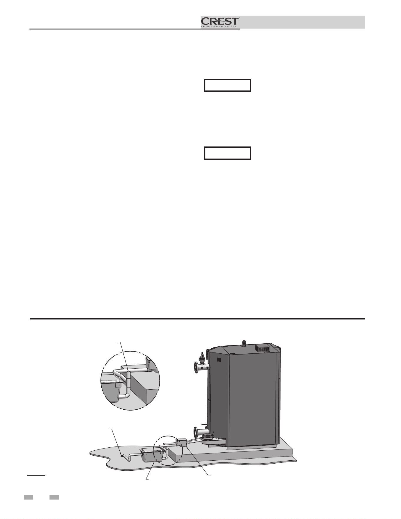
Installation & Operation Manual
8 Condensate disposal
Condensate drain
1. The Crest is a high efficiency appliance that produces
condensate.
2. The rear of the boiler has a 1 inch (25.4 mm) stainless steel
drain fitting and a 3/8 inch (9.8 mm) stainless steel vent line
for connection to the condensate trap.
3. Connect the 1 inch (25.4 mm) fitting to the 1 inch (25.4
mm) fitting on the condensate trap with the factory
supplied silicone hose. Secure the hose to the condensate
trap and the boiler using the factory supplied hose clamps.
4. Connect the 3/8 inch (9.8 mm) fitting to the 3/8 inch (9.8
mm) fitting on the condensate trap (shipped loose) with
the factory supplied silicone hose. Secure the hose to the
condensate trap and the boiler using the factory supplied
hose clamps.
5. The condensate trap must be installed at the same level or
below the boiler base.
6. The condensate trap is sized for a 1" PVC outlet connection
pipe.
7. Plug the wiring connection from the condensate trap into
the connector located on the back of the unit.
8. Slope condensate tubing down and away from the boiler
into a drain or condensate neutralizing filter. Condensate
from the Crest will be slightly acidic (typically with a pH
from 3 to 5). Install a neutralizing filter if required by local
codes.
A neutralizer kit (FIG. 8-1) is available from the factory.
The neutralizer kit must be placed on a surface that is a
minimum of 3 inches lower than the condensate trap with
field supplied piping (vacuum break) installed between the
condensate trap and the neutralizer kit.
Use materials approved by the authority
having jurisdiction. In the absence of
other authority, PVC and CPVC pipe
must comply with ASTM D1785 or
D2845. Cement and primer must comply
with ASME D2564 or F493. For Canada
use CSA or ULC certified PVC or CPVC
pipe, fittings, and cement.
10. A condensate removal pump is required if boiler is below
the drain. When installing a condensate pump, select one
approved for use with condensing boilers and furnaces.
The pump should have an overflow switch to prevent
property damage from condensate spillage. The switch
should be wired to the auxiliary device proving switch
terminals on the low voltage connection board.
NOTICE
NOTICE
To allow for proper drainage on large
horizontal runs, a second line vent may
be required and tubing size may need to
increase to 1 inch (25 mm).
The condensate line must remain
unobstructed, allowing free flow of
condensate. If condensate is allowed to
freeze in the line or if the line is obstructed
in any other manner, condensate can exit
from the boiler tee, resulting in potential
water damage to property.
CONDENSATE TRAP
SAME LEVEL OR BELOW
BOILER BASE
NEUTRALIZER KIT
(OPTIONAL)
3" MINIMUM BELOW
CONDENSATE TRAP
FLOOR DRAIN
OR DRAIN PAN
DETAIL
VACUUM
BREAK
IMG01042
Figure 8-1 Condensate Disposal
9. Do not expose condensate line to freezing temperatures.
46
NOTE: Neutralizer shown
for illustrative purposes only.
Actual neutralizer may vary.
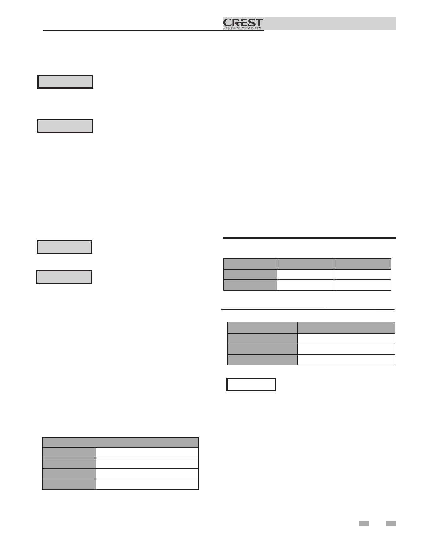
47
Installation & Operation Manual
9 Start-up
Check/control Fill Water chemistry
Conduct water quality testing prior to
installing the appliance. Various options
are available to adjust water quality.
IMPORTANT
Boiler Water & Fill Water / Make-Up Water
Hardness Specifications
Lochinvar recommends the following for properly filling your
boiler with the appropriate water chemistry for closed loop
boilers. Good boiler water quality will help extend the life of
the appliance by reducing the effects of magnetite scale build-
up and corrosion in closed loop systems.
Pre-Commissioning Cleaning
1. Prior to fill and start-up, flush the entire heating system.
2. Isolate the boiler and clean the entire heating system with
an approved pre-commissioning cleaner (comparable to
Sentinel X300 and Fernox F3) in accordance with the
manufacturer’s recommendation to remove debris and
prolong the life of the heat exchanger.
3. Clean all water filtering devices in the system.
4. Flush the cleaning solution out of the entire system and
refill.
CAUTION
CAUTION
Do not use petroleum-based cleaning or
sealing compounds in the boiler system.
Gaskets and seals in the system may be
damaged. This can result in substantial
property damage.
DO NOT flush the cleaning solution
and debris from the system through the
boiler.
DO NOT fill the system with distilled
or reverse osmosis water. Lochinvar
recommends filling with demineralized
water when treatment is necessary.
CAUTION
Level I Level II
System Volume
≤ 1,000 gal > 1,000 gal
Total Hardness
≤ 12 gpg ≤ 9 gpg
Table 9A Boiler Water & Fill Water / Make-Up Water
Hardness Specifications
Table 9A provides guidelines for the maximum allowable
hardness levels for both the boiler water and the make-up
water based on the system volume. There are two (2) levels of
allowable hardness depending on the size of the system.
1. Initial system fill must meet the recommended values
of hardness for boiler water / make-up water. This may
require water treatment such as using demineralizers.
2. Consult local water treatment companies for hard water
areas (above the values listed in Table 9A). Hardness levels
that are above the values listed in Table 9A can lead to lime
scale build-up throughout the boiler system.
3. Fill Water recommendations meet or exceed the EPA
primary and secondary water standards. Not all items
from the standards are listed. See the EPA Standards for a
complete list of water quality guidelines.
Boiler Water Specifications
Table 9B Additional Boiler Water Specifications
Boiler Water
Total Dissolved Solids
≤ 2,000 ppm
pH Level
7.0 - 11.0
Chlorides
< 150 ppm
Fill Water / Make-Up Water
TDS
< 350 ppm
pH Level
6.5 - 9.5
Chlorides
< 150 ppm
Iron
< 0.3 ppm
Chloride Concentration
1. Do not fill boiler with water containing chlorine in excess
of 150 ppm.
2. Do not use the boiler to directly heat swimming pool or
spa water.
Iron Concentration
1. Do not fill boiler with water containing iron in excess of 0.3
ppm.
Fill Water / Make-Up Water
NOTICE
If the boiler water iron levels exceed
the value recommended for Fill Water /
Make-Up Water it will be necessary to
install a magnetic separator and treat the
boiler water with an approved multi-metal
corrosion inhibitor.
A Magnetic Separator is recommended
any time a boiler is retrotted into a pre-
existing system, or installed in any system
containing steel or cast iron pipe.
48
Installation & Operation Manual
9 Start-up (continued)
Freeze protection fluids
1. Use glycol only if needed for freeze protection fluid.
2. Make sure to flush the boiler system before adding glycol.
3. Determine the freeze protection fluid quantity using
system water content, following the fluid manufacturer's
instructions. Boiler water content is listed on page 6.
Remember to include expansion tank water content.
4. Local codes may require a backflow preventer or actual
Lochinvar recommends inhibited
propylene glycol solutions which are
specifically formulated for hydronic
systems. Never use automotive antifreeze.
⚠WARNING
Dissolved oxygen can have a negative effect on the boiler
system. Oxygen can cause iron oxide to generate iron
deposits. Oxygen may also increase the rate of corrosion
on non-stainless steel parts of the system. A low pH level
combined with oxygen further enhances its corrosive effects.
After boiler installation, check for air leaks in the following
areas:
• Suction gasket
• Pump
• Air valve
• O-ring gaskets
Fill and test water system
1. Fill system only after ensuring the water meets the
requirements of this manual.
2. Close automatic and manual air vents and boiler drain
valve.
3. Fill to correct system pressure. Correct pressure will vary
with each application.
a. The minimum cold water fill pressure for a system is
12 psi.
b. Pressure will rise when the boiler is turned ON and
system water temperature increases.
4. At initial fill and during boiler startup and testing, check
the system thoroughly for any leaks. Repair all leaks before
proceeding further.
CAUTION
Eliminate all system leaks. Continual
fresh makeup water will reduce boiler
life. Scale can build up in the heat
exchanger, reducing heat transfer,
overheating the heat exchanger, and
causing heat exchanger failure.
disconnect from city water supply.
5. When using freeze protection fluid with automatic fill,
it is suggested to install a water meter to monitor water
makeup. Freeze protection fluid may leak before the
water begins to leak, causing the concentration to drop,
which reduces the freeze protection level.
6. The freeze protection set points may be lowered when
freeze protection fluid is used (see the Crest Service
Manual).
7. Consult the glycol manufacturer for details on the
suggested mix of glycol and water for the desired freeze
protection level and the de-rate effect it will have on the
boiler output.
Test / replace freeze protection fluid
1. For systems using freeze protection fluids, follow the fluid
manufacturer's instructions.
2. Freeze protection fluid must be replaced periodically due
to degradation of inhibitors over time.
3. It is recommended to test the glycol concentration
annually and adjust within the desired set points.
Oxygen prevention
Precautions include installing a water meter to evaluate the
fresh water volume entering the system (should be no more than
5% system volume). Additional volumes of fresh water could
indicate that a leak is present.
Additional Considerations
1. Monitoring pH, chlorides, TDS, and hardness levels can
prolong the life of the appliance by reducing the effects
of magnetite and scale build-up, corrosion, and erosion.
Check for leaks to ensure that fresh water is not entering
the system.
2. Continual fresh make-up water will reduce boiler life.
3. Scale build-up in the heat exchanger reduces heat transfer,
overheats the stainless steel heat exchanger, and causes
failure.
4. The addition of oxygen carried in by make-up water can
cause internal corrosion in the system components.
5. Leaks in the boiler or piping must be repaired at once to
prevent excessive make-up water. For this purpose, it is
recommended to install a water meter to easily check the
amount of make-up water entering the system. Make-up
water volume should not exceed 5% of the total system
volume per year. NOTE: When make-up water is added,
make sure the chemical additives are added to maintain the
correct level.
6. An approved multi-metal corrosion inhibitor (comparable
to Sentinel X100 or Fernox F1) is recommended at the
correct concentration and in the manner recommended by
the manufacturer.
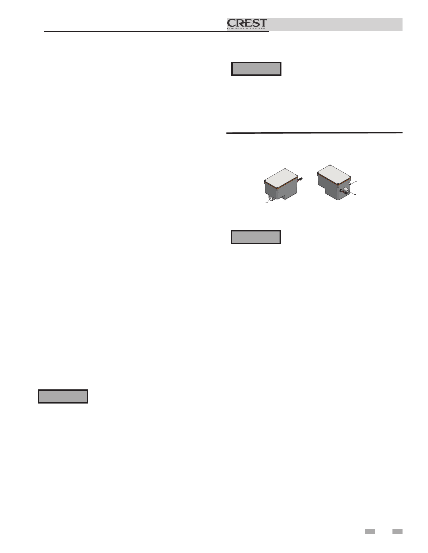
49
Installation & Operation Manual
9 Start-up
Check for gas leaks
Before starting the boiler, and during
initial operation, smell near the floor and
around the boiler for gas odorant or any
unusual odor. Remove the top access
panel and smell the interior of the boiler
enclosure. Do not proceed with startup
if there is any indication of a gas leak.
Use an approved leak detection solution.
Repair any leaks at once.
DO NOT adjust or attempt to measure
gas valve outlet pressure. The gas valve
Propane boilers only – Your propane
supplier mixes an odorant with the propane
to make its presence detectable. In some
instances, the odorant can fade, and the
gas may no longer have an odor. Before
startup (and periodically thereafter), have
the propane supplier verify the correct
odorant level in the gas.
Check thermostat circuit(s)
1. Disconnect the two external wires connected to the
enable terminals on the connection board.
2. Connect a voltmeter across these two incoming wires.
Close each thermostat, zone valve, and relay in the
external circuit one at a time and check the voltmeter
reading across the incoming wires.
3. There should NEVER be a voltage reading.
4. If a voltage does occur under any condition, check and
correct the external wiring. (This is a common problem
when using 3-wire zone valves.)
5. Once the external boiler enable wiring is checked and
corrected if necessary, reconnect the external thermostat
circuit wires to the connection board. Allow the boiler to
cycle.
Inspect condensate system
Inspect/check condensate lines and fittings
1. Inspect the condensate drain line, condensate PVC
fittings and condensate trap.
FROM CONDENSAT
E
VENT ON BOILER
FROM CONDENSATE
DRAIN ON BOILER
TO FLOOR DRAI
N
OR NEUTRALIZE
R KIT
1" PVC / CPVC CONNECTION
Figure 9-1 Condensate Trap
⚠WARNING
⚠WARNING
⚠WARNING
Purge air from water system
1. Purge air from system:
a. Connect a hose to the purge valve (see purge/drain
valve in the piping diagrams on pages 33 through 36).
Route the hose to an area where water can drain and be
seen.
b. Close the boiler or system isolation valve between the
purge valve and fill connection to the system.
c. Close zone isolation valves.
d. Open the quick-fill valve on the cold water makeup
line.
e. Open purge valve.
f. Open the isolation valves one zone at a time. Allow
water to run through the zone, pushing out the air.
Run until no noticeable air flow is present. Close
the zone isolation valves and proceed with the next
zone. Follow this procedure until all zones are purged.
g. Close the quick-fill water valve and purge valve and
remove the hose. Open all isolation valves. Watch that
system pressure rises to correct cold-fill pressure.
h. After the system has operated for a while, eliminate
any residual air by using the manual air vents located
throughout the system.
i. If purge valves are not installed in the system, open the
manual air vents in the system one at a time, beginning
with the lowest floor. Close the vent when water
squirts out. Repeat with remaining vents.
2. Open the automatic air vent (diaphragm-type or bladder
type expansion tank systems only) one turn.
3. Open other vents:
a. Starting on the lowest floor, open air vents one at a
time until water squirts out.
b. Repeat with remaining vents.
4. Refill to correct pressure.
is factory set for the correct outlet pressure. This setting
is suitable for natural gas and propane, requiring no field
adjustment. Attempting to alter or measure the gas valve
outlet pressure could result in damage to the valve, causing
potential severe personal injury, death, or substantial
property damage.
50
Installation & Operation Manual
9 Start-up (continued)
Final checks before starting the boiler
q Read the Crest Service Manual to familiarize yourself
with SMART TOUCH control module operation. Read
this manual, page 50 for proper steps to start boiler.
q Verify the boiler and system are full of water and all
system components are correctly set for operation.
q Verify the preparation procedures of Section 9, pages 46
- 48 have been completed.
q Verify electrical connections are correct and securely
attached.
q Inspect vent piping and air piping for signs of deterioration
from corrosion, physical damage or sagging. Verify air
piping and vent piping are intact and correctly installed
per this manual.
Start the boiler
1. Read and follow the Operating instructions in FIG. 9-2,
page 50.
If boiler does not start correctly
1. Check for loose connections, blown fuse or service switch
off?
2. Is external limit control (if used) open? Is boiler water
temperature above 200°F (93°C)?
3. Is the boiler receiving a call for heat?
4. Is gas turned on at meter and boiler?
5. Is incoming gas pressure less than 4 inches w.c. (.99 kPa)?
6. Ignition problems are especially noticeable in new LP
installations and also in empty tank situations. This can
also occur when a utility company shuts off service to an
area to provide maintenance to their lines.
If none of the above corrects the problem, refer to the
Troubleshooting Section of the Crest Service Manual.
Check system and boiler
q Check water piping
1. Check system piping for leaks. If found, shut down the
boiler and repair immediately. (See WARNINGS on
pages 46 - 48 (startup) regarding failure to repair leaks.)
2. Vent any remaining air from the system using manual
vents. Air in the system will interfere with circulation
and cause heat distribution problems and noise.
q Check vent piping and air piping
1. Check for gastight seal at every connection, seam of air
piping, and vent piping.
Venting system must be sealed gastight
to prevent flue gas spillage and carbon
monoxide emissions, which will result in
severe personal injury or death.
q Check gas piping
1. Check around the boiler for gas odor following the
procedure on page 37 of this manual (connecting gas
supply piping).
If you discover evidence of any gas leak,
shut down the boiler at once. Find the
leak source with a bubble test and repair
immediately. Do not start the boiler again
until corrected. Failure to comply could
result in severe personal injury, death, or
substantial property damage.
Check flame and combustion
1. Turn the main power off to the boiler by placing the “On/
Off ” switch in the OFF position.
2. Remove the fitting from the flue collector. Note:
Combustion measurements will be made at this point.
3. Insert the probe from a combustion analyzer into the
hole left by the removal of the fitting.
4. Turn the main power on to the boiler by placing the “On/
Off ” switch in the ON position.
⚠WARNING
⚠WARNING
For dual fuel models, reference the Crest
Dual Fuel Supplemental Manual.
NOTICE
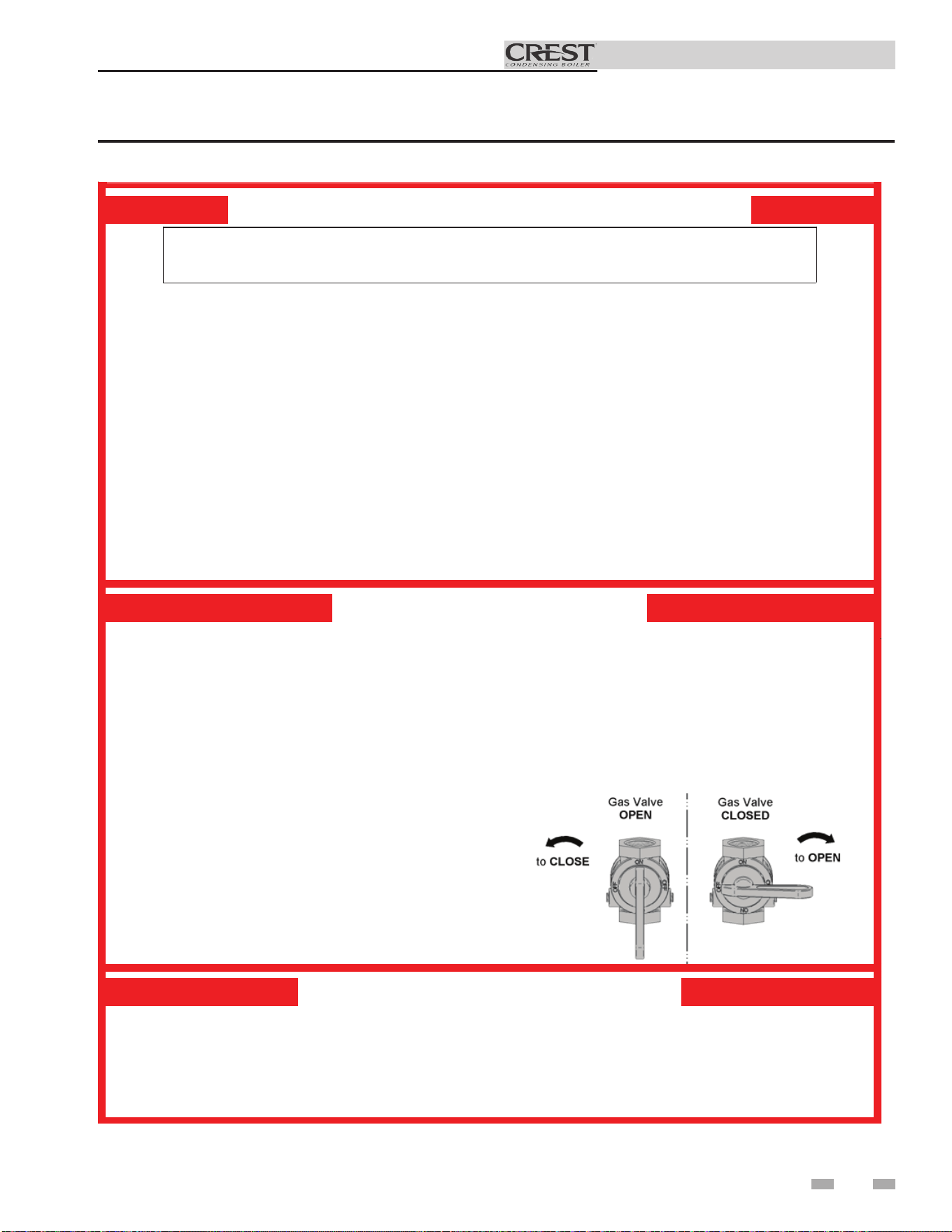
51
Installation & Operation Manual
FOR YOUR SAFETY READ BEFORE OPERATING
WARNING: If yo u do not follow these instructions exactly, a fire or explosion
may result causing property damage, personal injury, or loss of life.
A. This appliance does not ha ve a pilot. It is
equipped with an ignition device which
automati call y lights th e burner. Do not try
to light the burner by hand.
B. BEFOR E OPER ATING smell all ar ound
the appliance area for gas. Be sure to
smell next to the floor because some gas
is heavier than air and will settle on the
floor.
WHAT TO DO IF YOU SMELL GAS
• Do not tr y to light any ap pl iance.
• Do not touch any electric switch; do
not use any phone in your buildi ng.
• Im mediatel y call your gas supp lier from a
neighbor ’s phone. Follow the gas supplier’s
instructions.
• If you cannot reach your gas supplier , call
th e fire department.
C. Use only your hand to turn the gas control knob .
Never use tools. If the handle will not turn by
hand , don’t try to re
pair it, call a qualified service
te chnician. Force or attempted repair may
result in a fire or expl osion.
D. Do not use this appliance if any part has been
unde r water. Immediately call a qu al ified
service technician to inspect th e applianc e and
to replace any part of the control system and
any gas control which has been unde r water.
OPERATING INSTRUCTIONS
1. STOP! Read the safety information
above on this label.
2. Set the thermostat to lowest sett ing.
3. Turn off all electr ic power to the
applianc e.
4. This appliance is equi pped with an
ignition device which automatically lights
the burner . Do not try to light th e burner
by hand.
5. Remove front door.
6. Turn gas shutoff valve counterclockwise
to “OFF”. Handle will be perpendicular to
pipe. Do not force.
7. Wait five (5) minutes to clear out an y gas.
If you then smell gas, STOP! Follow “B”
in the safety information above this label.
If you don’t smell gas, go to ne xt step.
8. Turn gas shutoff valve clockwise to “ON”.
Handle will be parallel to pipe.
9. In stal l front door.
10. Turn on al l electric power to applianc e.
11. Se t thermo
stat to desired setting.
12. If the appl iance will not oper ate, follow the
instructions “To Turn Off Gas To Appliance” and
call yo ur service technician or gas supplier .
TO TURN OFF GAS TO APPLIANCE
1. Set the thermostat to lowest sett ing.
2. Turn off all electr ic power to the ap pl iance
if service is to be perfor med.
3. Remove front door.
4. Turn gas shut off valve counterclockwise to
“OFF”. Handle wi ll be pe rpen di cular to pipe.
Do not force.
5. In stal l front door.
LBL2 0053 REV B
Figure 9-2 Operating Instructions
9 Start-up
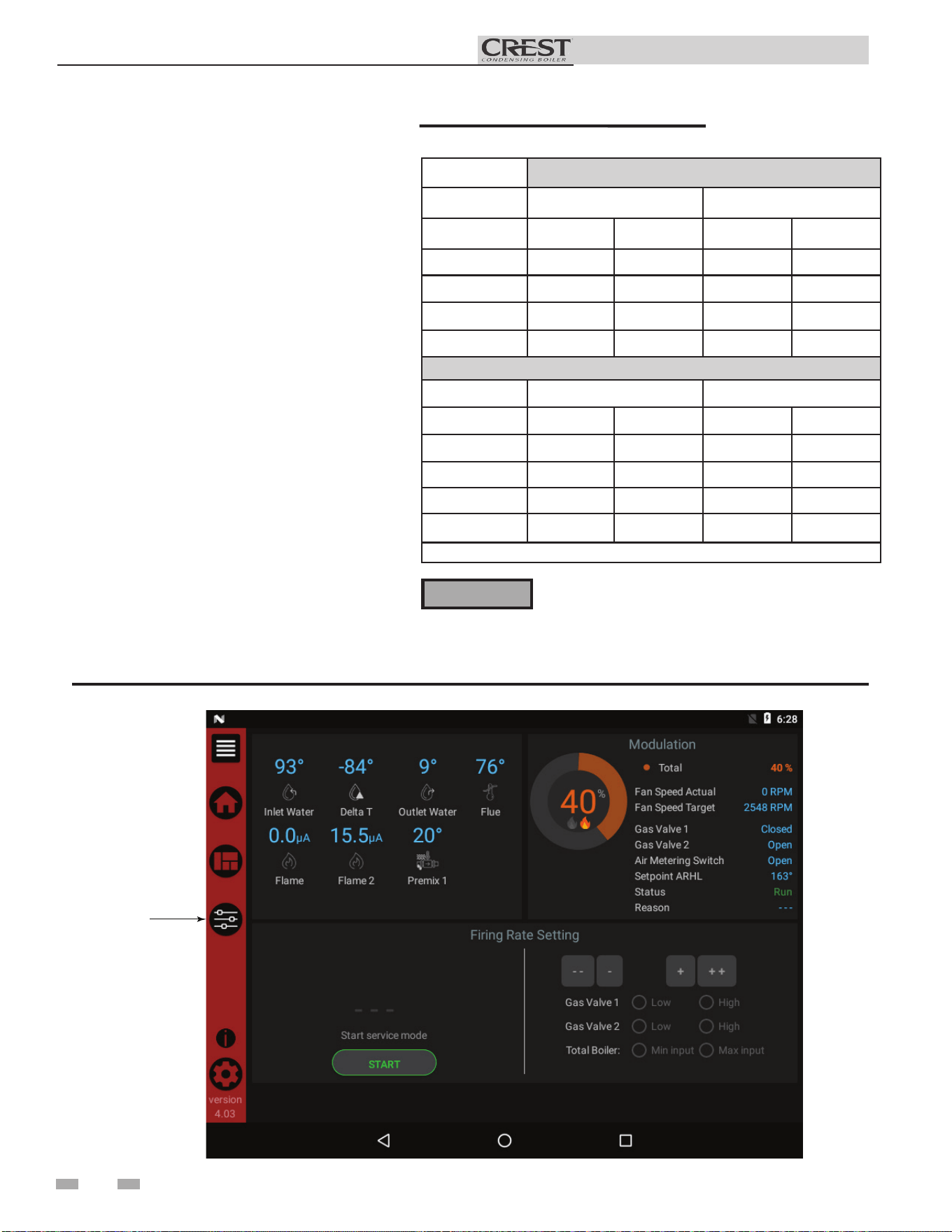
52
Installation & Operation Manual
9 Start-up (continued)
Check flame and combustion
(continued)
5. Navigate to the Setup Screen from the Home
Screen by pressing the SETUP button along
the left side of the screen. Enter the installer
password.
6. Select the Service Maintenance Screen. The
tabs will scroll (up and down) to reveal more
options. See the Crest Service Manual for more
detailed information.
7. Once the boiler has modulated up to rate,
measure the combustion. The values should
be in the range listed in Table 9B (this page).
CO levels should be less than 200 ppm for a
properly installed unit. If the combustion is
not within range reference the Troubleshooting
Section in the Crest Service Manual for possible
causes and corrective actions.
8. Once the heater analysis is complete, test the
safety shutoff device by turning the manual
shutoff valve to the OFF position and ensuring
the heater shuts down and registers an alarm.
Open the manual shutoff valve and reset the
control.
9. Turn the main power off to the boiler and
replace the fitting into the flue pipe connection.
10. Ensure the boiler is placed back into normal
operation.
Table 9B Flue Products Chart
You must replace the fitting to prevent flue gas spillage
into the room. Failure to comply could result in severe
personal injury, death, or substantial property damage.
⚠WARNING
Figure 9-3 Service Maintenance Screen
Flue Products
Natural Gas
Units
751-2001
2501-6001
Gas Valve
CO
2
(%) O
2
(%) CO
2
(%) O
2
(%)
Valve 1 High 9.2 4.6 9.2 4.6
Valve 1 Low 9.0 4.9 8.5 5.7
Valve 2 High 9.3 4.4 9.5 4.2
Valve 2 Low 8.7 5.5 8.8 5.4
Propane
Units
751-2001
2501-6001
Gas Valve
CO
2
(% O
2
(%) CO
2
(% O
2
(%)
Valve 1 High 11.0 4.1 11 4.1
Valve 1 Low 10.0 5.6 9.9 5.7
Valve 2 High 11.1 4.0 11.1 4
Valve 2 Low 10.7 4.6 10.1 5.5
**All set points should be within +/- 0.2%**
SETUP
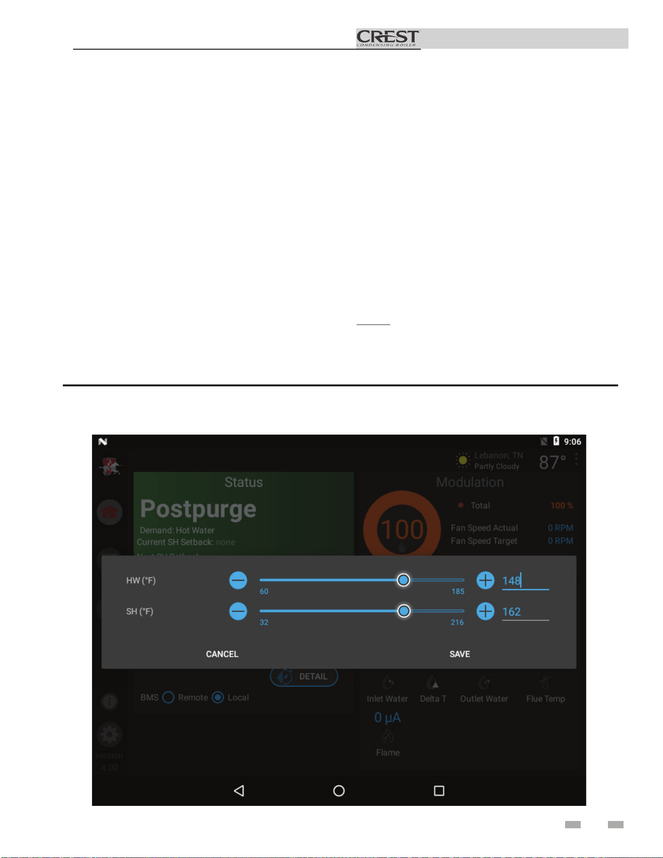
53
Installation & Operation Manual
9 Start-up
Set space heating set point temperature
During normal operation, set point temperatures can be
adjusted from the Home Screen by pressing the DETAILS
button on the bottom of the screen (see FIG. 9-4).
1. To change a set point, use the set point slider feature
or the PLUS (+) and MINUS (-) buttons
to adjust the set points as shown in FIG. 9-4.
2. Once the set point has been adjusted to the desired
setting, press the Door Menu slider (top left) or the
SETUP button.
3. Press the APPLY CHANGES button on the top of the
screen.
NOTE: The APPLY CHANGES button must be pressed to
complete programming of the controls. Failure to press the
APPLY CHANGES button will result in an unprogrammed
control. The Door Menu button will become highlighted
when there are changes that can be applied.
Set space heating operation
Verify space heat circulator mode
The system pump output can be programmed to never run
(OFF), run only when a space heating demand is present
(ON), or run continuously except during warm weather
shutdown (WWSD). If the boiler is not heating an indirect
HW (Hot Water Generator) tank, it also turns on the boiler
pump. After the space heating call for heat ends, and the
system pump is programmed as ON, the system pump
continues to run for a short period of time. If the boiler
pump was running, it continues to run for a short period
of time as well. These pump delays are factory set to 30
seconds. If different delays are desired, the appropriate
parameters in the control must be changed. See the Crest
Service Manual for a detailed explanation of this procedure.
Figure 9-4 User Set Point Screen
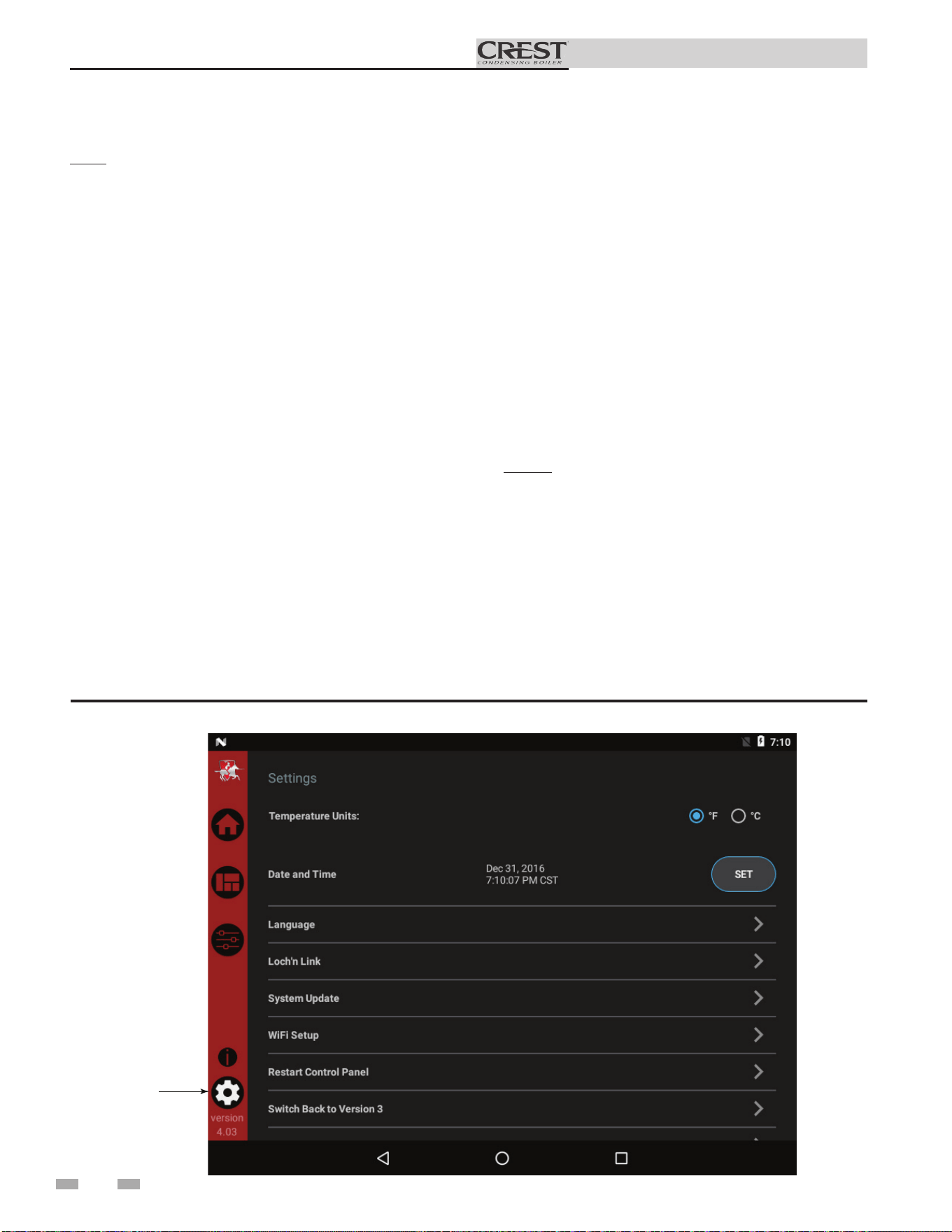
54
Installation & Operation Manual
Set Hot Water Generator (HW) operation
Note: For more detailed instructions, please refer to the
Crest Service Manual.
Verify HW mode
There are two (2) modes of operation for HW. In Normal
Mode, when a HW demand begins, the control will start
the HW pump, turn off the boiler pump (if running), and
modulate to bring the outlet temperature to the HW boiler
set point. The maximum firing rate may be limited in this
mode if desired.
In Zone Mode it is assumed that the indirect HW tank is
piped as a zone on the primary loop. When a HW demand
begins, the control will turn on the HW pump output, and
raise the system temperature set point to the HW boiler set
point (if higher). The boiler pump will be turned on. The
system pump may be forced on, forced off, or not changed,
depending on the System Pump Mode selected (reference
the Crest Service Manual for details). In this mode, any
low temperature zones (such as radiant heating) may need
additional controls to limit the water temperature sent to
those zones.
Set HW boiler target temperature
When in the HW Mode, the control will modulate to
maintain the boiler outlet temperature or system supply
temperature to a set point. This set point is set at the factory
to 180°F. If a different set point is desired, the appropriate
parameter in the control must be changed. See the Crest
Service Manual for a detailed explanation of this procedure.
9 Start-up (continued)
Set maximum HW fan speed
If the rated input of the indirect tank is less than the maximum
output of the boiler, change the maximum HW fan speed
setting to limit the boiler output accordingly, see the Crest
Service Manual for a detailed explanation of this procedure.
Set clock
The SMART TOUCH control has a built-in clock that it uses
for its night setback feature and for logging events. This clock
must be set when the boiler is installed, and anytime the boiler
has been powered off for more than one day. Use the following
procedure to set the clock:
1. Press the SETTINGS button under the Lochinvar logo (see
FIG. 9-5).
2. Press the SET button across from the date and time.
3. Proceed to set the date, time, and time zone.
NOTE: Automatic Time Zone will not work.
4. Temperature units and WiFi may also be set here. These
items may be used to automatically sync the time.
5. Press the Home, View, or Back button to exit.
Figure 9-5 Settings Screen
SETTINGS
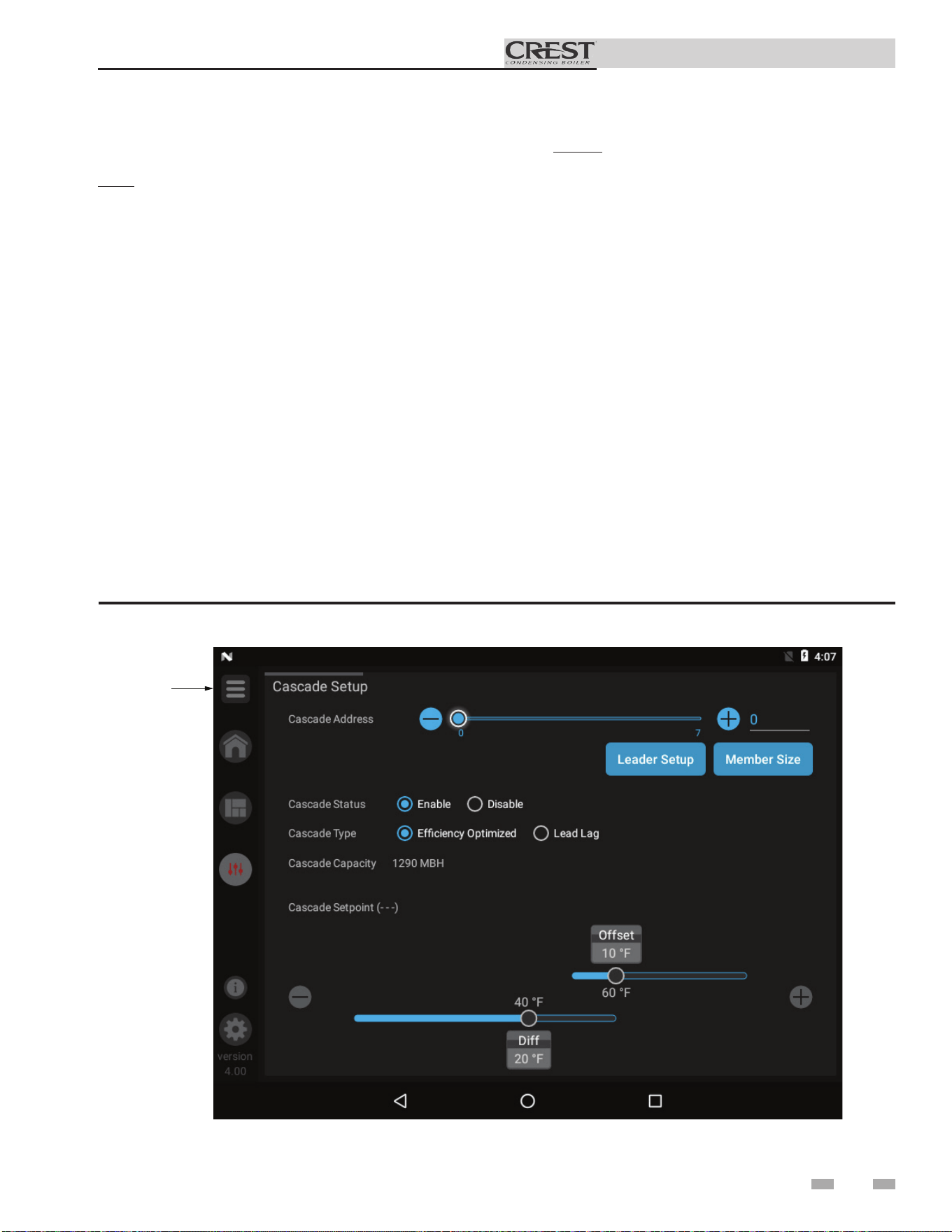
55
Installation & Operation Manual
9 Start-up
Figure 9-6 Cascade Screen
Configuration of the cascade
Note: For more detailed instructions, please refer to the Crest
Service Manual.
When installing a Cascade system, all units must be
programmed for Cascade to operate. Access the Cascade
Setup options as follows:
1. Press the SETUP button on the left side of the display
screen.
2. Enter the installer password.
3. Select the Cascade option as shown in FIG. 9-6.
4. Each unit must have a unique address set. The leader has
more options which are described in the Crest Service
Manual.
5. Once all the updates are complete, press the Door Menu
slider (top left) or the SETUP button.
6. Press the APPLY CHANGES button on the top of the
screen.
NOTE: The APPLY CHANGES button must be
pressed to complete programming of the controls.
Failure to press the APPLY CHANGES button will
result in an unprogrammed control. The Door Menu
button will become highlighted when there are changes
that can be applied.
DOOR
MENU

56
Installation & Operation Manual
General
How the boiler operates
The Crest uses an advanced stainless steel heat exchanger
and electronic control module that allows fully condensing
operation. The blower pulls in air and pushes flue products out
of the boiler through the heat exchanger and flue piping. The
control module regulates blower speed to control the boiler
firing rate. The gas valves sense the amount of air flowing into
the boiler and allow only the right amount of gas to flow.
How the control modules operate
The Crest boiler is equipped with a SMART TOUCH control
module. The SMART TOUCH control module receives inputs
from boiler sensors and external devices. The control module
activates and controls the blower and gas valves to regulate heat
input and switches the boiler, Hot Water Generator (HW),
and system pumps on and off as needed. The user programs
the control module to meet system needs by adjusting control
parameters. These parameters set operating temperatures and
boiler operating modes.
Control inputs and outputs
Enable
This input tells the boiler to provide water for space heating.
Hot Water Generator (HW) tank thermostat
This input tells the boiler to provide water for heating an
indirect HW tank.
0 - 10V BMS input (set point or power)
The Crest can be controlled by a Building Management
System (BMS) using a 0 - 10 VDC signal. The control can be
configured by the installer to use this signal to either control set
point or firing rate.
0 - 10V System Pump speed input
When a variable speed system pump is used, and there is a 0 -
10V signal available from the pump speed control, this signal
may be connected to the boiler. Doing so will allow the boiler
to anticipate changes in the BTU’s needed by the system as the
system flow changes, and therefore, help the boiler to maintain
the desired system temperature. Connect the - input terminal
to the COM or - output terminal on the pump speed control,
and the + input terminal to the 0 - 10V or + output terminal on
the pump speed control. Note that the voltage on these inputs
must never go below ground.
HW priority
The SMART TOUCH control allows the connection of a HW
thermostat or tank sensor to the low voltage connection board.
When a tank sensor is connected, the HW thermostat input is
ignored. When a boiler is programmed for HW Normal Mode,
the maximum firing rate can be limited to match the input
rating of the indirect tank coil.
HW / space heating (SH) cycling
If a HW call for heat is received while a space heating call is in
progress, and the HW is in Normal Mode, the control will start
the HW pump and shut the boiler pump off. The system pump
will remain on. For stand-alone boilers, if the space heating call
is still active while the HW call is in operation, the control will
wait for 30 minutes (time adjustable by installer) then it will
switch back to the space heating demand. There is a timer to
switch from space heating to HW and a timer to switch from
HW to space heating. The control will switch back and forth
until one of the heat demands end. This function does not
apply to cascade systems.
Controlling sensor
The control module is programmed to use the outlet sensor
as the control sensor by default. If a system supply sensor
is connected, the control automatically uses it as the control
sensor. The control module may be programmed to use the
inlet sensor as the control sensor instead. In this case, the
control will use the system return sensor if it is connected.
Anti-cycling
After a space heating demand has been satisfied, the control
will delay the next space heating call for a set time period (time
is adjustable by the installer). The time delay will be bypassed
if the inlet water temperature drops too far during the delay.
Boiler, system, and HW pump control
When a space heating call for heat starts and no HW call is on,
the boiler pump is turned on. The system pump will turn on
also if it is programmed to do so. If a HW call for heat is on,
the boiler pump will wait to turn on until just before the HW
pump turns off. After the space heating call for heat ends, the
boiler pump will run for an additional period of time.
When a HW call for heat starts, the HW pump is turned on. If
a space heating call for heat is on, the boiler pump will turn off
a few seconds after the HW pump turns on.
Louver
When the boiler needs to control combustion air louvers,
connect a 24 VAC louver relay to the two (2) Louver Relay
terminals. Connect the Louver End Switch to the Louver
Proving Switch input on the Low Voltage Connection Board.
Temperature control
Modulation
The Crest is capable of modulating its firing rate from a
minimum of 4-6% (depending on model) to a maximum of
100%. The firing rate is dictated by the call for heat (i.e., space
heating or hot water generation), the heating load, ramp delay
(if enabled), and various other temperature limitations.
10 Operating information

10 Operating information
57
Installation & Operation Manual
Gradient limiting
If during operation of the boiler the outlet water temperature
is rising too quickly, the control will reduce the firing rate to
its lowest setting.
Outdoor air reset
If an outdoor air sensor is connected, the control module will
calculate the set point based on the programmed reset curve.
The installer can change the slope of the reset curve by several
adjustable parameters. The user can limit the maximum set
point for the system using the space heating set point.
Boost function
If outdoor air reset is active, the boost temperature is not 0,
a space heating demand has been active continuously for a
set period of time (time adjustable by installer) and there has
been no HW demands, the control will increase the set point
by a fixed number of degrees (adjustable by installer). This
process will continue until the space heating demand ends, the
set point reaches the programmed set point or a maximum of
20 increases has occurred. Once the system heat demand is
satisfied, the set point will revert to the value determined by
the reset curve.
Night setback
The controller may be programmed to reduce the space
heating set point and/or Hot Water Generator set point for
each demand during a certain time each day. A start and stop
time for each demand can be programmed for each day of the
week. The controller can be programmed to reduce the tank
set point as well. A different set of start and stop times can be
programmed each day of the week.
Flame current support
To prevent nuisance shutdowns when the boiler is firing at
minimum rates, the control will increase the firing rate when
the flame signal drops too low.
ModBus / BACnet
The Crest boiler can be connected to and controlled by a
Building Automation System through a ModBus or BACnet
interface. Connect the A and B wires to the A and B terminals.
If connecting another cable (in a daisy chain), connect the
shield wire of the first cable to one of the shield terminals, and
the shield wire of the second cable to the other shield terminal.
If it is desired to ground the cable shield at the heater, connect
the shield wire to one of the shield terminals, and install a
jumper across the two (2) terminals in connector X5 on the
ModBus / BACnet interface board.
0-10V Rate output
A 0-10V signal which indicates the firing rate of the heater
is available. This output may be connected to a Building
Management System (BMS) to allow it to monitor the actual
firing rate. Connect the - terminal to the COM or - terminal
on the BMS, and connect the + terminal to the 0 - 10V or +
terminal on the BMS.
Ramp Delay
For systems with lower flow, the SMART TOUCH can limit
the firing rate (when enabled) when a space heating call for
heat starts, or when switching from a DHW call for heat to a
space heating call for heat. There are six (6) limits that can be
programmed, as well as six (6) time intervals corresponding to
each limit. The sixth limit will also limit the firing rate for the
rest of the call for heat.
Protection features
Outlet temperature, flue temperature, and temperature
rise limiting
The outlet water temperature is monitored by the boiler outlet
temperature sensor. When the outlet temperature exceeds
185°F, the unit will reduce the fan speed. If the outlet water
temperature exceeds 195°F (90°C) the control will shut the unit
down until the minimum off time has expired and the outlet
drops 10°F (5.5°C).
The control module monitors the flue temperature by a sensor
located in the flue exhaust. If the flue temperature exceeds
215°F (101°C) the control will reduce the maximum fan speed.
If the flue temperature exceeds 225°F (107°C) the control will
shut the unit down. The unit will restart automatically once
the flue temperature drops 10°F (6°C) and the minimum off
time has expired.
The control monitors the temperature difference between
the inlet and the outlet sensor. If this difference exceeds
70°F (21°C) the control will reduce the fan speed. If the
temperature difference exceeds 80°F (27°C) the control will
shut the unit down. The unit will restart automatically once
the temperature difference has dropped below 50°F (28°C) and
the minimum off time has expired.
Freeze protection
DO NOT install the boiler in a room likely to freeze.
The following integral feature of the SMART TOUCH control
module provides some protection for the boiler only -- not for
the system.
• The SMART TOUCH control module provides
freeze-up protection as follows when the boiler
water temperature drops below 45°F (7°C):
• Below 45°F (7°C), the boiler and system pumps (if
enabled) operate constantly.
• Below 37°F (3°C), the boiler turns on.
• Boiler and pumps turn off if boiler water
temperature rises above 43°F (6°C).
This feature of the SMART TOUCH control
module does not eliminate the possibility
of freezing. The installation must still
use recognized design, installation and
maintenance practice to prevent freeze
potential for the boiler and system.
⚠ CAUTION

58
Installation & Operation Manual
10 Operating information (continued)
Monitor external limits
Connections are provided on the connection board for
external limits such as an additional high limit. The
SMART TOUCH control will shut off the burner and
inhibit relighting whenever any of these external limits
open.
Run-time and alarm outputs
The boiler provides dry contacts for indicating when the
boiler is running, and when it is unable to operate.
Run-time and cycle counting
The control uses four timers to monitor the total hours of
burner operation:
75 - 100% 50 - 75%
25 - 50% <25%
The control uses four (4) ignition counters to monitor
the amount of boiler cycles. The first counter counts all
ignitions of the control. The second counter counts only
ignition attempts that have failed. The third and fourth
counters are the same as the first and second respectively,
but can be reset by the installer.
Service reminder
The control can be programmed for service reminder
notification. This notification will become active when
either a set amount of time has expired, or a set amount of
running hours or cycles has expired (all adjustable by the
installer). The service reminder notification can be reset
by the installer. The service company’s name and phone
number can be programmed to display when service is due.
Error logging
The control will hold in memory the last 10 blocking faults
as well as the last 10 lockout faults. The date and time of
the occurrence will be recorded as well. Only the 10 most
recent occurrences will be held in memory.
Boiler temperature regulation
Operating temperature (target)
The SMART TOUCH control module senses water
temperature and regulates boiler firing and firing rate to
achieve a target temperature. The target temperature can
be set between 32°F (0°C) and 185°F (85°C).
• Target temperature is fixed when the outdoor
sensor is not installed.
• Target temperature is calculated as described
under “Outdoor Reset Operation” and “Target
Temperature Boost” when the outdoor sensor is
connected.
High limit operations
The Crest SMART TOUCH control has two (2) integral limits,
one auto reset and one manual reset. The Crest also has one
auxiliary manual reset high limit. The integral and auxiliary
high limits are UL353 certified.
When the outlet temperature exceeds 195°F (90.6°C) (Installer
Adjustable Parameter), integral auto reset high limit action
occurs. The boiler will shut down until the outlet water cools
down and the timer expires.
If the outlet temperature exceeds 200°F (93.3°C) (User
Adjustable Dial), auxiliary manual reset high limit action
occurs. The boiler will shut down until the outlet water cools
down and the boiler is reset through the user interface.
If the outlet temperature exceeds 205°F (93.3°C) (Installer
Adjustable Parameter), integral manual reset high limit action
occurs. The boiler will shut down until the outlet water cools
down and the boiler is reset through the user interface.
Low water cutoff protection
A low water cutoff device with test and reset functionality is
provided in the boiler as standard equipment.
Flow sensing device
The SMART TOUCH control module uses temperature sensing
of both supply and return temperatures of the heat exchanger.
If the flow rate is too low or the outlet temperatures too high,
the control module modulates down and will shut the boiler
off. This ensures boiler shutdown in the event of low flow
conditions.
Outdoor reset operation, if used
Target temperature with outdoor reset
This feature improves the system’s efficiency as the outdoor
temperature warms up.
See the Crest Service Manual to change the settings.
Reset curve
The reset curve looks at outdoor air temperature and adjusts
the set point.
NOTICE
If a mechanical flow switch is required to
meet local code requirements the Crest
boiler can be equipped with a field supplied
outlet flow switch. Please wire to the Louver
Proving Switch terminals.

10 Operating information
59
Installation & Operation Manual
Cascade
When multiple boilers are installed, they can be wired together
in a cascade sequence. A maximum of eight boilers can be
controlled from a single control. In this application one boiler
would be designated as the Leader control and all others
would be designated as Member controls.
Once the Leader boiler receives a call for heat from the Enable
input, the 0 - 10 VDC input, ModBus or BACnet, the control
will determine what the set point will be. If outdoor air reset
is desired, connect the outdoor air sensor to the terminals on
the Low Voltage Connection Board on the Leader boiler. The
set point will be calculated based on the programmed reset
curve parameters. See the Crest Service Manual to program
the reset curve. If outdoor air reset is not desired, do not
connect the outdoor air sensor. A fixed temperature set point
can be programmed into the control, or provided through the
ModBus or BACnet interface.
If the water temperature at the controlling sensor is less than
the set point + the turn-off offset - the off-on differential, the
control will initiate a call for heat on the Cascade (see the
Crest Service Manual for an explanation of the offset and
differential). The Leader will energize the lead boiler on the
Cascade. For a new startup this will be the Leader boiler.
The two (2) types of Cascade control are listed below:
Efficiency optimization
Efficiency optimization is chosen when the application is such
that overall heating efficiency is most important. The Cascade
will fire the boilers in a way that is the most efficient. This
allows more boilers to fire at one time, at a lower rate, thus
more efficient. This Cascade is NOT allowed in a common
vent application.
Lead/Lag
The Lead/Lag method is chosen when the application requires
firing as few boilers at a time as possible. This method will not
bring on another boiler until the current number of boilers
cannot meet the demand. This Cascade is also required when
cascading boilers in a common vent application.
The parameters for both types of Cascade are adjustable.
Reference the Crest Service Manual for a more detailed
description of these adjustments.
Sequence of the cascade
To equalize the run time of all boilers on the Cascade, the
firing sequence will automatically be changed at set intervals.
For the first 24 hours after initializing the Cascade, the
sequence will be changed every hour. After that the sequence
will be changed once every 24 hours.
HW operation with cascade
For normal mode HW operation any boiler(s) in the Cascade
can be selected to provide heat for a HW call. Select a boiler to
be designated as the HW boiler. Connect the HW thermostat
or sensor to the terminals on the Low Voltage Connection
Board marked for the corresponding device. When the boiler
receives a HW call, the Leader control will take that boiler
out of the Cascade sequence. If another boiler is available, the
Leader will start it up to take its place.
The HW boiler will adjust its set point to the programmed
HW boiler set point and will adjust its firing rate to maintain
this. Once the HW call has been satisfied, the Leader control
will place that boiler back into the Cascade sequence.
Switching of the boiler between HW operation and SH
operation when there is a call for both does not occur in
Cascade Mode.
When HW is programmed for Zone Mode, connect the HW
thermostat or tank sensor to the Leader boiler. When a HW
call is received, the Leader will modulate the entire Cascade
to bring the system supply temperature up to the HW boiler
set point (if higher).
Night Setback and Ramp Delay operations with
cascade
Night Setback and Ramp Delay operation of the boilers within
the Cascade are available. Programming will be done through
the Leader boiler. Refer to the Crest Service Manual for
information regarding Night Setback and Ramp Delay.
10 Operating information (continued)
60
Installation & Operation Manual
Sequence of operation
1.
Upon a call for heat, the control turns on the appropriate pumps (system and boiler pumps for a space heating call,
HW pump for a hot water generator call).
2.
The control confirms that the low water cutoff contacts are closed and energizes the louvers (optional) and damper
(optional) relays.
3.
The control confirms that the proof of closure switch (Model FB 6001 only), gas pressure switch, blocked drain
switch, limits, louver proving switch (optional) and damper proving switch (optional) contacts close. The proof of
closure valve (FB 6001 only) opens and the Pre-Purge cycle begins.
4.
The control confirms the blower is up to the desired speed, and the air pressure switch is closed.
5.
Once the Pre-Purge cycle is complete, the control lowers the blower speed, initiates sparking of the ignition electrode,
and opens gas valve 1.
6.
After a short wait, the control stops sparking and checks for the presence of flame current through the flame sense
electrode.
7.
If the control does not detect flame current: Models FB0751-2001 - The control will repeat the ignition cycle after
the required post purge and pre-purge cycles. Models FB2501-6001 - Loss of flame will result in safety shutdown and
lockout, requiring manual reset.
8.
If the control detects flame current, the control will hold the blower speed constant for a few seconds to allow the
flame to stabilize, then begin modulating the firing rate in order to maintain the controlling sensor to the desired set
point temperature.
9.
If the current call for heat is for space heating and a HW call for heat becomes active, the control will turn on the HW
pump relay output, then turn off the boiler pump. It will then modulate the blower speed in order to maintain the
outlet temperature to the desired HW outlet set point temperature.
10.
If the boiler is unable to maintain the desired set point using gas valve 1, control will transition to the larger gas valve
2. The blower will modulate to a fixed speed and the air metering valve will start to open. As it opens, gas valve 2 will
be turned on and gas valve 1 will be turned off. If the flame should be lost at any time during this process, the control
will immediately try to reignite the burner. Once the air metering valve is fully open and the flame is confirmed to
be present, the control will hold the fan speed constant for a few seconds in order to allow the flame to stabilize. The
fan speed will then modulate as needed to maintain the set point. If the flame is not present when the air metering
valve is fully open, the boiler will go through a complete shutdown and restart of the burner. If the heat load should
decrease sufficiently, a similar process is used to transition from gas valve 2 to gas valve 1.
11.
Once both the space heating and HW calls for heat are satisfied, the control will turn off the gas valve and begin the
Post-Purge cycle. Any pumps that are running will begin their respective Pump Delay cycles.
12.
At the end of the Post-Purge cycle, the louver relay contacts will de-energize.
13.
The control verifies that the blowers stop running and the blower proving switches open.
14.
At the end of the Pump Delay cycle(s), the pump(s) will be turned off.
Note: This unit is equipped with two (2) gas train systems. Gas Train 1 will fire first. If the demand cannot be met by the
first gas train, the second gas train (Gas Train 2) will fire.
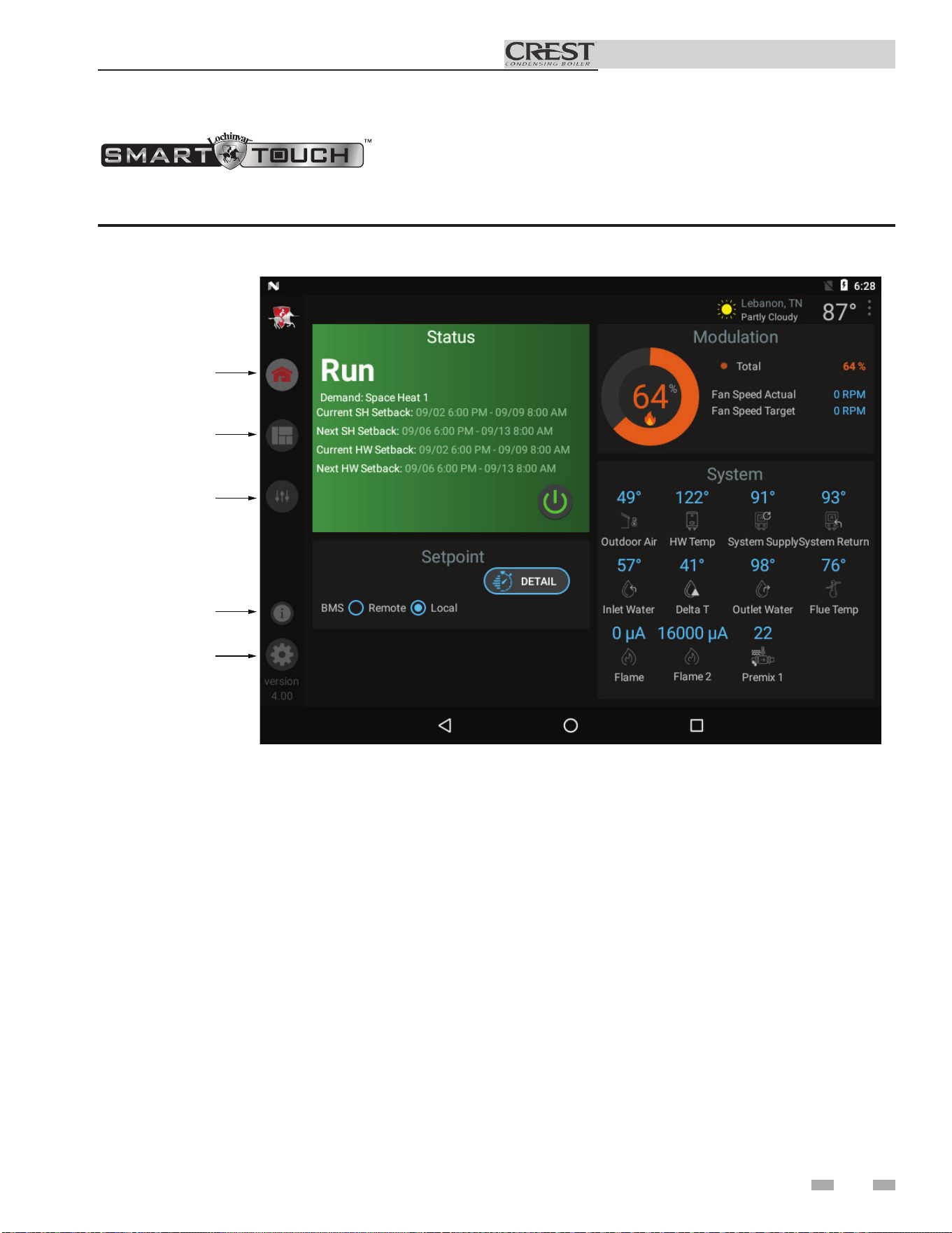
10 Operating information
61
Installation & Operation Manual
w/Crest CON•X•US Interface (CCI)
Figure 10-1 Home Screen
The Home Screen displays the available basic system information divided into the following sections: Status, Demand,
Modulation, Sensors, and Navigation.
HOME
VIEW
SETUP
INFORMA
TION
SETTINGS
• The Status Section is located on the top left of the screen
and displays how the unit is currently running (i.e. Off,
Stand-by, Blocking, and Lockout) including: current
driving demand, the next Hot Water Setback scheduled,
the reason for any blocking or lockout, and a power button.
• The Demand Section is located on the bottom left of the
screen and displays information about the targets and
limits of the current demand being serviced.
• The Modulation Section is located on the top right of the
screen and displays the target modulation of the unit. This
section also includes target and actual fan speeds.
• The Sensor Section is located on the bottom right of the
screen and displays both factory installed and field installed
sensor including: Outdoor Air, Hot Water Temperature,
System Supply, System Return, Inlet Water, Delta T, Outlet
Water, Flue Temperature, and Flame Current.
• The Navigation Section is located down the left side of the
screen. There are five (5) sections located below the
Lochinvar icon: Home, View, Setup, Information
(About), and Settings. The Home Section is the screen
shown above. The View Section provides more detailed
information including subsections for: History, Cascade,
Graphing, and a complete list of current Sensor Values.
The Setup Section has several screens to aid in setting
up the appliance. The Setup Section includes screens for
adjusting: Set Points, Pump Settings, Cascade, BMS, Ramp
Delay, and Night Setback. The Information Section
provides information about the hardware and software
including the current software version of the interface, the
version of the boiler control, and the CON·X·US device
serial number. The Setting Section enables several interface
setup features including: Time Setup, Temperature Unit
Select, Loch’n Link, System Update, and WiFi Setup.
62
Installation & Operation Manual
11 Maintenance
Maintenance and annual startup
Table 11A Service and Maintenance Schedules
Service technician
(see the following pages for instructions)
General:
• Address reported problems, if any
• Inspect interior; clean and vacuum if
necessary;
• Clean condensate trap and fill with fresh
water
• Check for leaks (water, gas, flue,
condensate)
• Verify flue and air lines in good condition
and sealed tight
• Check system water pressure/system
piping/expansion tank
• Check fill water meter
• Test boiler water. When test indicates,
clean system water with approved
system restorer following manufacturer’s
information.
• Check control settings
• Check the ignition and both flame sense
electrodes (sand off any deposits; clean
and reposition)
• Check wiring and connections
• Perform start-up checkout and
performance verification per Section 9.
• Flame inspection (stable, uniform)
• Check both flame signals (at least 10
microamps at high fire)
• Clean the heat exchanger
• Test low water cutoff (reference the
Crest Service Manual).
If combustion or performance
indicate need:
• Clean heat exchanger
• Remove and clean burner using
compressed air only
• Clean the blower wheels
ANNUAL START-UP
Owner maintenance
(see the Crest User’s Information Manual for
instructions)
Daily
• Check boiler area
• Check pressure/temperature
gauge
Monthly
• Check vent piping
• Check air piping
• Check air and vent termination
screens
• Check relief valve
• Check condensate drain system
• Check Magnetic Separator
Every
6 months
• Test low water cutoff
• Reset button (low water
cutoff)
• Check boiler piping (gas and
water) for leaks
• Operate relief valve
End
of season
months
• Shut boiler down (unless boiler
used for domestic hot water)
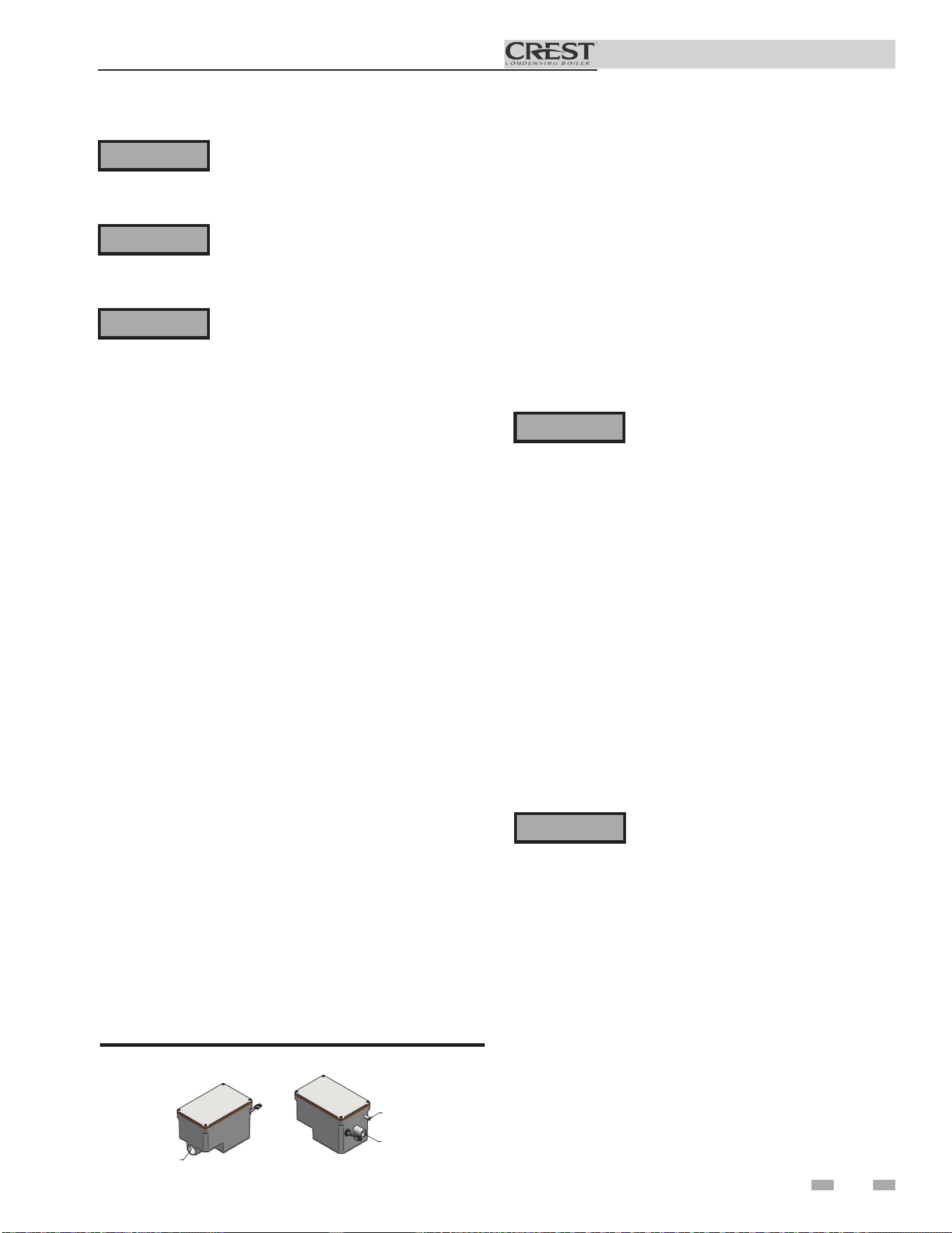
63
Installation & Operation Manual
11 Maintenance
Follow the service and maintenance procedures given throughout this manual and in component literature
shipped with the boiler. Failure to perform the service and maintenance could result in damage to the boiler
or system. Failure to follow the directions in this manual and component literature could result in severe
personal injury, death, or substantial property damage.
The boiler should be inspected annually only by a qualified service technician. In addition, the maintenance
and care of the boiler designated in Table 11A and explained on the following pages must be performed to
assure maximum boiler efficiency and reliability. Failure to service and maintain the boiler and system could
result in equipment failure.
Electrical shock hazard – Turn off power to the boiler before any service operation on the boiler except as
noted otherwise in this instruction manual. Failure to turn off electrical power could result in electrical shock,
causing severe personal injury or death.
Address reported problems
1. Inspect any problems reported by the owner and correct
before proceeding.
Inspect boiler area
1. Verify that boiler area is free of any combustible materials,
gasoline and other flammable vapors and liquids.
2. Verify that air intake area is free of any of the contaminants
listed in Section 1 of this manual. If any of these are
present in the boiler intake air vicinity, they must be
removed. If they cannot be removed, reinstall the air and
vent lines per this manual.
Inspect boiler interior
1. Remove the front access covers and inspect the interior of
the boiler.
2. Vacuum any sediment from inside the boiler and
components. Remove any obstructions.
Clean condensate trap
1. Inspect the condensate drain line, vent line, condensate
PVC fittings, and condensate trap.
Flush condensate trap with water
1. Remove the four (4) screws securing the top cover to the
condensate trap and remove the cover (FIG. 11-1).
2. Locate the plastic ball inside the float tube. Verify there
is nothing under the ball causing it to not seat properly.
3. Fill with fresh water until the water begins to pour out of
the drain.
4. Replace the top cover and the screws removed in Step 1.
Eliminate all system or boiler leaks.
Continual fresh makeup water will
reduce boiler life. Minerals can build up,
reducing heat transfer, overheating heat
exchanger, and causing heat exchanger
failure. Leaking water may also cause
severe property damage.
1. Inspect all water and gas piping and verify to be leak free.
2. Look for signs of leaking lines and correct any problems
found.
3. Check gas line using the procedure found in Section 6
- Gas Connections.
Check all piping for leaks
⚠WARNING
⚠WARNING
⚠WARNING
⚠WARNING
FROM CONDENSAT
E
VENT ON BOILER
FROM CONDENSATE
DRAIN ON BOILER
TO FLOOR DRAI
N
OR NEUTRALIZE
R KIT
1" PVC / CPVC CONNECTION
Figure 11-1 Condensate Trap
Flue vent system and air piping
1. Visually inspect the entire flue gas venting system and air
piping for blockage, deterioration or leakage. Repair any
joints that show signs of leakage. Verify that air inlet pipe
is connected and properly sealed.
2. Verify that boiler vent discharge and air intake are clean
and free of obstructions.
Failure to inspect for the above conditions
and have them repaired can result in
severe personal injury or death.
⚠WARNING
Check water system
1. Verify all system components are correctly installed and
operational.
2. Check the cold fill pressure for the system. Verify it is
correct (must be a minimum of 12 psi (82.7 kPa)).
3. Watch the system pressure as the boiler heats up (during
testing) to ensure pressure does not rise too high.
Excessive pressure rise indicates expansion tank sizing
or performance problem.
4. Inspect automatic air vents and air separators. Remove
air vent caps and briefly press push valve to flush vent.
Replace caps. Make sure vents do not leak. Replace any
leaking vents.

Installation & Operation Manual
11 Maintenance (continued)
Check expansion tank
1. Expansion tanks provide space for water to move in
and out as the heating system water expands due to
temperature increase or contracts as the water cools.
Tanks may be open, closed or diaphragm or bladder type.
See Section 5 - Hydronic Piping for suggested best location
of expansion tanks and air eliminators.
Check fill water meter
1. Check fill water meter for water usage. If the amount
exceeds 5% of your system volume, you could have a leak.
Have the system checked for leaks and fixed by a qualified
service technician.
Test boiler water
1. Test boiler water. Reference the Crest Installation and
Operation Manual for guidelines. When test indicates,
clean system water with approved system restorer following
the manufacturer’s information.
Check boiler relief valve
1. Inspect the relief valve and lift the lever to verify flow.
Before operating any relief valve, ensure that it is piped with
its discharge in a safe area to avoid severe scald potential.
Read Section 5 - Hydronic Piping before proceeding
further.
Safety relief valves should be re-inspected
AT LEAST ONCE EVERY THREE YEARS,
Following installation, the valve lever
must be operated AT LEAST ONCE A
YEAR to ensure that waterways are clear.
2. After following the above warning directions, if the relief
valve weeps or will not seat properly, replace the relief valve.
Ensure that the reason for relief valve weeping is the valve
and not over-pressurization of the system due to expansion
tank waterlogging or undersizing.
⚠WARNING
⚠WARNING
Inspect ignition and flame sense
electrodes
1. Remove the ignition and both flame sense electrodes
from the burner plate.
2. Remove any deposits accumulated on the ignition/
flame sense electrodes using sandpaper. If the electrodes
cannot be cleaned satisfactorily, replace with new ones.
3. Replace ignition/flame sense electrodes, making sure the
gaskets are in good condition and correctly positioned.
Check ignition ground wiring
1. Inspect boiler ground wire from the heat exchanger
access cover to ground terminal strip.
2. Verify all wiring is in good condition and securely
attached.
3. Check ground continuity of wiring using continuity
meter.
4. Replace ground wires if ground continuity is not
satisfactory.
Check all boiler wiring
1. Inspect all boiler wiring, making sure wires are in good
condition and securely attached.
Check control settings
1. Navigate to the Setup Screen and check all settings. See
Section 1 of the Crest Service Manual. Adjust settings if
necessary. See Section 1 of the Crest Service Manual for
adjustment procedures.
2. Check settings of external limit controls (if any) and
adjust if necessary.
Perform start-up and checks
1. Start boiler and perform checks and tests specified in
Section 9 - Start-up.
2. Verify cold fill pressure is correct and that operating
pressure does not go too high.
Certain naturally occurring mineral deposits may adhere
to the valve, rendering it inoperative. When manually
operating the lever, water will discharge and precautions
must be taken to avoid contact with hot water and to avoid
water damage. Before operating lever, check to see that a
discharge line is connected to this valve directing the flow
of hot water from the valve to a proper place of disposal.
Otherwise severe personal injury may result. If no water
flows, valve is inoperative. Shut down the boiler until a new
relief valve has been installed.
64
by a licensed plumbing contractor or authorized inspection
agency, to ensure that the product has not been affected by
corrosive water conditions and to ensure that the valve and
discharge line have not been altered or tampered with illegally.
Certain naturally occurring conditions may corrode the valve
or its components over time, rendering the valve inoperative.
Such conditions are not detectable unless the valve and its
components are physically removed and inspected. This
inspection must only be conducted by a plumbing contractor
or authorized inspection agency – not by the owner. Failure
to re-inspect the boiler relief valve as directed could result in
unsafe pressure buildup, which can result in severe personal
injury, death, or substantial property damage.
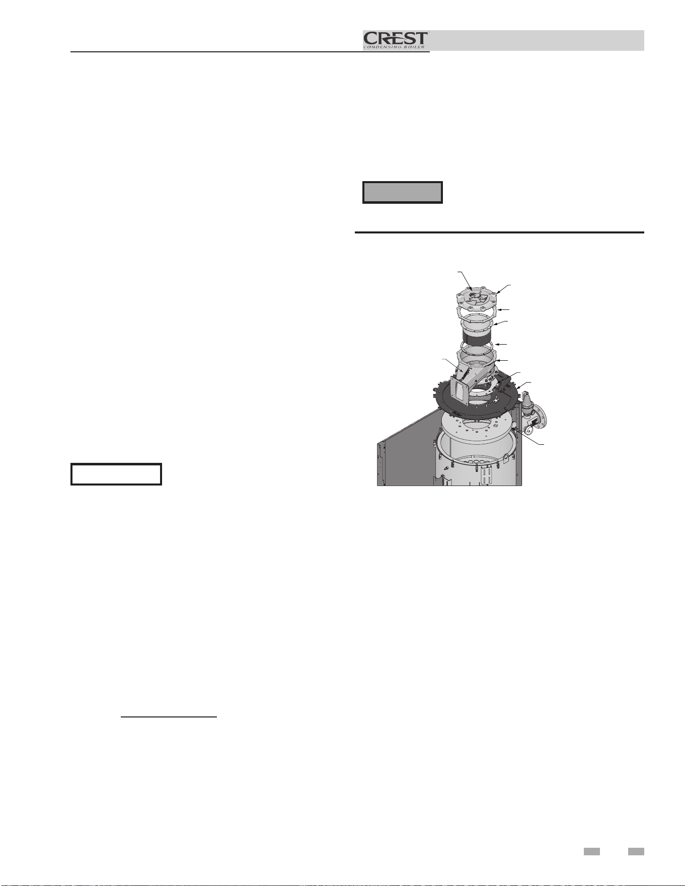
65
Installation & Operation Manual
11 Maintenance
Check flame signal
1. At high fire of each combustion system, the flame signal
shown on the display should be at least 10 microamps.
2. A lower flame signal may indicate a fouled or damaged
flame sense electrode. If cleaning the flame sense electrodes
does not improve, ground wiring is in good condition, and
ground continuity is satisfactory, replace the flame sense
electrode.
3. See Section 3 - Troubleshooting in the Crest Service Manual
for other procedures to deal with low flame signal.
GAS/AIR MANIFOLD GASKET
BURNER
BURNER GASKET
GAS/AIR MANIFOLD
GAS/AIR MANIFOLD GASKET
BURNER TOP PLATE ASSEMBL
Y
FIBERBOARD
LOCHINVAR LOGO
GAS/AIR MANIFOLD COVER
NOTE: Be sure to pay clos
e
attention to the Lochinvar logo.
A
lign the logo with the Lochinvar
logo on the gas/air manifold to
ensure proper assembly
.
Pay close attention to the bolt
pattern, as the gas/air manifold
assembly can only be installed
one way
.
DIR #2000508208
Figure 11-2 Burner Assembly
Check burner flame
1. Inspect flame through observation windows.
2. If the flame is unsatisfactory at either high fire or low
fire, remove and clean the burner. Clean the burner
thoroughly using a vacuum cleaner or compressed
air. Do not use compressed air to clean the burner if
cleaning is performed inside a building.
• Shut down the boiler:
- Follow the “To Turn Off Gas to Appliance”
instructions for the boiler in Section 9 - Startup
of the Crest Installation and Operation Manual.
- Do not drain the boiler unless it will be
exposed to freezing temperatures. If using
freeze prevention fluid in system, do not drain.
3. Allow time for the boiler to cool to room temperature if
it has been firing.
4. Remove the top access panel(s) to gain access to the gas/
air manifold assembly.
5. Remove the gas/air manifold burner access cover (FIG.
11-2).
6. Remove the nuts/washers holding the burner to the gas/
air manifold assembly.
7. Remove the burner from the gas/air manifold assembly.
NOTICE
The burner gasket, burner, burner
baffle, and gas/air manifold access
cover can only be installed in one
orientation. All of these parts will
have to be re-installed correctly. To
ensure all of these parts are re-installed
correctly, align the logo on top of the
gas/air manifold cover with the logo on
the gas/air manifold as shown in FIG.
11-2. Be certain to pay close attention
to the bolt pattern when re-installing
the above parts.
Failure to follow the torquing specifications
listed in this manual could result in severe
personal injury or death.
⚠WARNING
10. Re-install the gas/air manifold burner access cover.
Tighten 3/8" nuts to 8 ft.-lbs. using the star pattern
sequence.
11. After firing the unit, re-tighten the nuts to the torque
specifications.
8. When replacing the burner, ensure gaskets are in good
condition and positioned correctly (FIG. 11-2).
9. When securing the burner and manifold, be sure to
tighten the nuts as follows:
a. Tighten the nuts in a star pattern sequence.
b. 0751-2001 Models: Tighten the 1/4" nuts,
securing burner to the cast manifold to a torque of
8 ft.-lbs.
2501-6001 Models: Tighten the 5/16" nuts,
securing burner to the cast manifold to a torque of
12 ft.-lbs.

Installation & Operation Manual
11 Maintenance (continued)
The boiler contains ceramic fiber materials.
Use care when handling these materials per
instructions on this page. Failure to comply
could result in severe personal injury.
⚠WARNING
Cleaning boiler heat exchanger
1. Shut down boiler:
• Follow the “To Turn Off Gas to Appliance” instructions
for the boiler in Section 9 - Startup.
• Do not drain the boiler unless it will be exposed to
freezing temperatures. If using freeze prevention fluid
in system, do not drain.
2. Allow time for the boiler to cool to room temperature if it
has been firing.
3. Remove the top access panel to remove the gas/air manifold
assembly.
4. Remove the nuts securing the burner to the burner
mounting plate. Remove the burner (reference FIG. 11-2
and follow the steps in Check Burner Flame on page 64).
5. Remove the nuts securing the burner mounting plate from
the heat exchanger and set aside. Remove the entire burner
mounting plate assembly.
6. Use a vacuum cleaner to remove any accumulation on the
tube sheet surfaces. Do not use any solvent.
7. Brush the heat exchanger (tube sheet, combustion chamber
walls, and tube entry) while dry using a nylon bristle brush.
Caution: DO NOT use a metal brush. Re-vacuum the heat
exchanger.
8. Finish cleaning using a clean cloth dampened with warm
water.
9. Temporarily remove the condensate drain line from the
condensate trap and route directly to a drain.
10. Rinse out debris with a low pressure water supply. The water
will drain through the condensate connection.
11. Allow the heat exchanger to thoroughly dry.
12. Reconnect the condensate drain line to the condensate trap.
13. Close isolation valves on piping to isolate boiler from
system. Attach a hose to the boiler drain and flush boiler
thoroughly with clean water by using purging valves to allow
water to flow through the water makeup line to the boiler.
Handling ceramic fiber materials
REMOVAL OF COMBUSTION CHAMBER
LINING
The combustion chamber insulation in this
appliance contains ceramic fiber material.
⚠WARNING
14. When securing the burner, be sure to tighten the nuts, but
DO NOT over-tighten. Tighten the nuts to a torque setting
of no more than 8 ft.-lbs for 0751-2001 models and 15 ft.-lbs
for 2501-6001 models. When securing the burner mounting
plate be sure to tighten the nuts, but DO NOT over-tighten.
Tighten the nuts to a torque setting of no more than 15
ft.-lbs for 0751-2001 models and 40 ft.-lbs for 2501-6001
models.
15. Replace the burner mounting plate assembly and gas/air
manifold assembly. Ensure gaskets are in good condition
and positioned properly. Restore boiler to operation.
16. Perform start-up and check-out procedures in the Check
Flame and Combustion - Section 9 - Startup on pages 49
and 51 of this manual.
Review with owner
1. Review the Crest User’s Information Manual with the
owner.
2. Emphasize the need to perform the maintenance schedule
specified in the Crest User’s Information Manual (and in
this manual as well).
3. Remind the owner of the need to call a licensed contractor
should the boiler or system exhibit any unusual behavior.
4. Remind the owner to follow the proper shutdown procedure
and to schedule an annual start-up at the beginning of the
next heating season.
66
Ceramic fibers can be converted to cristobalite in very high
temperature applications. The International Agency for
Research on Cancer (IARC) has concluded, “Crystalline silica
in the form of quartz or cristobalite from occupational sources
is carcinogenic to humans (Group 1).” Normal operating
temperatures in this appliance are below the level to convert
ceramic fibers to cristobalite. Abnormal operating conditions
would have to be created to convert the ceramic fibers in this
appliance to cristobalite.
The ceramic fiber material used in this appliance is an irritant;
when handling or replacing the ceramic materials it is advisable
that the installer follow these safety guidelines.
¢Avoid breathing dust and contact with skin and eyes.
• Use NIOSH certified dust respirator (N95). This type
of respirator is based on the OSHA requirements for
cristobalite at the time this document was written. Other
types of respirators may be needed depending on the
job site conditions. Current NIOSH recommendations
can be found on the NIOSH website at http://www.cdc.
gov/niosh/homepage.html. NIOSH approved respirators,
manufacturers, and phone numbers are also listed on this
website.
• Wear long-sleeved, loose fitting clothing, gloves, and eye
protection.
¢Apply enough water to the combustion chamber lining to
prevent airborne dust.
¢ Remove the combustion chamber lining from the boiler
and place it in a plastic bag for disposal.
¢ Wash potentially contaminated clothes separately from
other clothing. Rinse clothes washer thoroughly.
NIOSH stated First Aid.
¢ Eye: Irrigate immediately.
¢ Breathing: Fresh air.
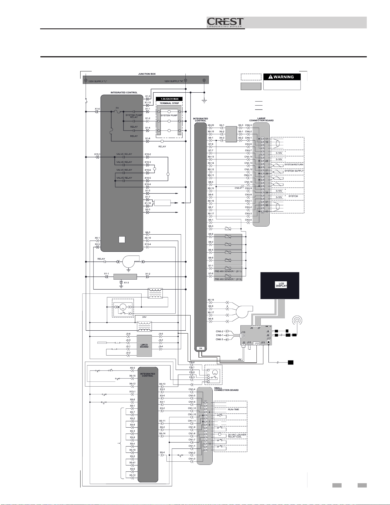
67
Installation & Operation Manual
12 Diagrams
Figure 12-1 Ladder Diagram_751 - 2001 Models
TERMINAL STRIP
TERMINAL STRIP
16
15
13
12
11
10
9
6
5
3
2
1
39
36
35
33
32
31
30
29
26
25
23
22
21
20
19
OUTLET SENSOR (S9)
OUTLET SENSOR (S1)
FLUE SENSOR
FLUE SENSOR (S10)
120VAC
NEUTRAL
ON/OFF
SWITCH
GAS
VALVE
(LARGE)
GAS
VALVE
(SMALL)
CONTACTOR
BOILER PUMP
CONTACTOR
DHW PUMP
CONTACTOR
BLOWER
BLOWER
1 2
3
BAS (AS APPLICABLE)
FLUE DAMPER
TRANSFORMER
1 2
3
TRANSFORMER
FLUE DAMPER
TEST
SWITCH
LWCO
PROBE
LWCO RESET
GPS1 GPS2
BLOCKED FLUE
SWITCH
BLOCKED DRAIN
SWITCH
ALARM
CONTACTS
CONTACTS
TANK
THERMOSTAT
LOUVER
PROVING
AUX
SWITCH 1
AUX
SWITCH 2
ENABLE
R
W
FLAME
SENSE 1
FLAME
SENSE 2
SPARK
GENERATOR
SPARK
ROD
SHIELD
SHIELD
A
B
BAS
OPTION
RATE
OUT
BOILER
PUMP OUT
SENSOR
SENSOR
TANK
SENSOR
OUTDOOR
SENSOR
BMS
IN
PUMP IN
SHIELD
SHIELD
A
B
CASCADE
INLET SENSOR
GROUND
1
2
5
BLOWER
BOX DEPICTS
OPTIONAL ITEMS
BOX DEPICTS
DUAL SENSOR
SINGLE HOUSING
HIGH VOLTAGE
LOW VOLTAGE
120 VAC
"X5"
BLOCK WIRING
IS MODEL
DEPENDENT
AIR VALVE
PRESS. SWITCH
BLOWER
AIR VALVE
HIGH LIMIT
SWITCH
M
M
DISCONNECT POWER
BEFORE SERVICING
BOILER PUMP
DHW PUMP
5.0 A
3.15 A
F2
LARGE GAS
LARGE GAS
SMALL GAS
SMALL GAS
USB
INTERFACE
X11
WIFI
DONGLE
USB CABLE
SW1
LG CON BRD
OPTIONAL
ETHERNET CABLE
OPTIONAL USB/WIFI
EXTENSION CABLE
BAS
E
GND
BAS
BOARD
(AS
APPLICABLE)
SHIELDED CABLE FROM X4
TO J12 OR J23 AS APPLICABLE
Notes:
1. All wiring must be installed in accordance with: local, state, provincial and national code requirements per either N.E.C.
in USA or C.S.A. in Canada.
2. If any original equipment wire as supplied with the appliance must be replaced, it must be replaced with wire having same
wire gauge (AWG) and rated for a minimum of 105°C. Exceptions: Replacement high voltage spark lead and
shielded
cables
must be purchased from the factory. Use of a non-approved spark lead or
shielded
cables can lead to operational problems
which could result in non-repairable damage to the integrated controller or other components.
3. Actual connector block locations may vary from those shown on diagrams. Refer to actual components for proper
connector block locations when using diagrams to troubleshoot unit.
LADDER DIAGRAM
100266646 REV C
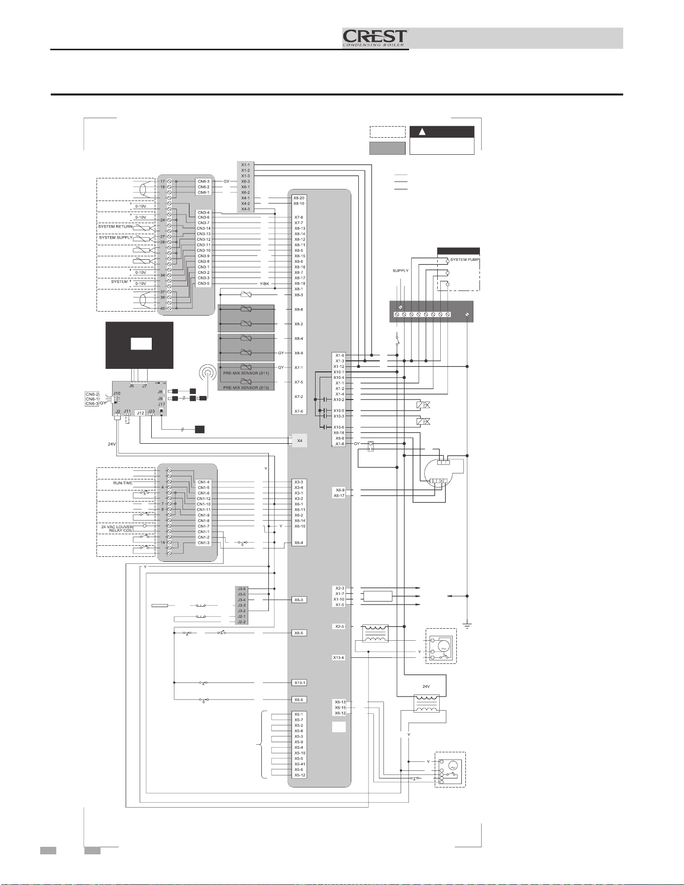
Installation & Operation Manual
12 Diagrams (continued)
Figure 12-2 Wiring Diagram_751 - 2001 Models
LCD
DISPLAY
!
WARNING
39
36
35
33
32
31
30
29
26
25
23
22
21
20
19
FLUE SENSOR (S10)
FLUE SENSOR
OUTLET SENSOR (S1)
OUTLET SENSOR (S9)
6
5
3
2
1
9
10
11
12
13
15
16
1
2
3
ALARM
CONTACTS
CONTACTS
TANK
THERMOSTAT
LOUVER
PROVING
AUX
SWITCH 1
AUX
SWITCH 2
SHIELD
SHIELD
A
B
BAS
OPTION
RATE
OUT
BOILER
PUMP OUT
SENSOR
SENSOR
TANK
SENSOR
OUTDOOR
SENSOR
BMS
IN
PUMP IN
SHIELD
SHIELD
A
B
CASCADE
BL
R
OR
OR
BL
BK
BR
R
HIGH LIMIT
SWITCH
R
R
R
PR
BL
R
BL
R
BR
W
OR
OR/W
P
W
BL
BK
LWCO
BOARD
OR
OR/BK
OR/BK
TEST
SWITCH
LWCO
PROBE
OR
OR
LWCO RESET
GPS1 GPS2
BR
OR
BLOCKED FLUE
SWITCH
PR
BLOCKED DRAIN
SWITCH
BK
ENABLE
INLET SENSOR
R
W
"X5"
BLOCK WIRING
IS MODEL
DEPENDENT
T
BK
BL
R/W
R
W
BR
L
N
GND
120V
ON/OFF
SWITCH
GND
GAS VALVE
(SMALL)
GAS VALVE
(LARGE)
BK
W
PR
T
OR
OR
BL
R
BL
G
BLOWER
BLOWER
R
BK
W
T
BK
FLAME SENSE 2
FLAME SENSE 1
SPARK
GENERATOR
SPARK ROD
FLUE DAMPER
TRANSFORMER
FLUE DAMPER
TRANSFORMER
BL
R
R
R
P
BK
BL
OR
BL
BK
INTEGRATED CONTROL
LARGE CONNECTION BOARD
SMALL CONNECTION BOARD
JUNCTION
BOX
BOILER PUMP
CONTACTOR
CONTACTOR
DHW PUMP
CONTACTOR
HIGH VOLTAGE
LOW VOLTAGE
120 VAC
1.5A EACH MAX
OR
AIR VALVE
PRESSURE SWITCH
OR/BK
OR
AIR VALVE
OR/W
BL
OR/R
M
1
M
2 3 5
1
2 3
USB
INTERFACE
X11
R
BL
E
GND
LG CON BRD
BAS
DISCONNECT POWER
BEFORE SERVICING
BOX DEPICTS
OPTIONAL ITEMS
BOX DEPICTS
DUAL SENSOR
SINGLE HOUSING
OPTIONAL USB/WIFI
EXTENSION CABLE
OPTIONAL
ETHERNET CABLE
SW1
USB CABLE
WIFI
DONGLE
COMMUNICATION
CONTROL BOARD
R
PR
BAS
BOARD
(AS APPLICABLE)
SHIELDED CABLE FROM X4
TO J12 OR J23 AS APPLICABLE
Notes:
1. All wiring must be installed in accordance with: local, state, provincial and national code requirements per either N.E.C. in USA or C.S.A. in Canada.
2. If any original equipment wire as supplied with the appliance must be replaced, it must be replaced with wire having same wire gauge (AWG) and rated for a
minimum of 105°C . Exceptions: Replacement high vo ltage spark lead and shielded cables must be purchased from the factory. Use of a non-approved spark lead
or shielded cables can lead to operational problems which could result in non-repairable damage to the integrated controller or other components.
3. Actual connector block locations may vary from those shown on diagrams. Refer to actual components for proper connector block locations when using
diagrams to troubleshoot unit.
WIRING DIAGRAM
100266647 REV C
68
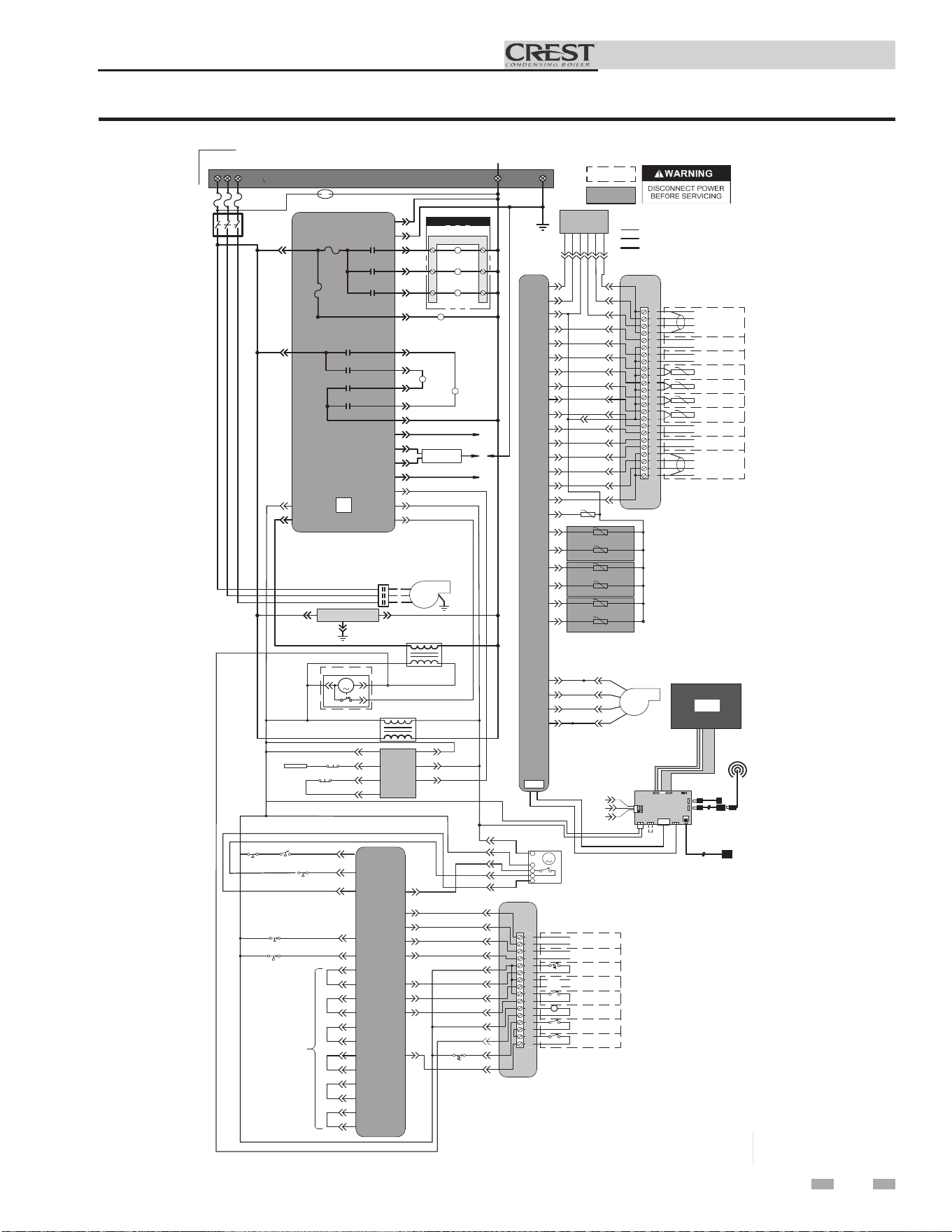
69
Installation & Operation Manual
12 Diagrams
Figure 12-3 Ladder Diagram_2501 - 3501 Models
JUNCTION BOX
TERMINAL STRIP
208V 3 SUPPLY
TERMINAL STRIP
208V SUPPLY "N"
NEUTRAL
INTEGRATED CONTROL
ON/OFF
SWITCH
F2
3.15 A
F4
5.0 A
SYSTEM PUMP
RELAY
BOILER PUMP
RELAY
DHW PUMP
RELAY
X1-1
X1-2
X1-4
X1-8
CONTACTOR
SMALL GAS
VALVE RELAY
LARGE GAS
VALVE RELAY
X1-4
X10-1 X10-2
X10-3
SMALL GAS
VALVE RELAY
LARGE GAS
VALVE RELAY
X10-6
X10-5
X10-4
GAS
VALVE
(LARGE)
GAS
VALVE
(SMALL)
TERMINAL STRIP
SYSTEM PUMP
CONTACTOR
BOILER PUMP
CONTACTOR
DHW PUMP
CONTACTOR
BLOWER
CONTACTOR
BLOWER
X6-10
X13-4
X6-1
X2-5
FLUE DAMPER
TRANSFORMER
M
1 2
3
24V
TRANSFORMER
FLUE DAMPER
X6-3
X1-12
X1-3
LWCO
BOARD
TEST
SWITCH
LWCO
PROBE
LWCO RESET
J3-6
J3-3
J2-1
J2-2
J3-5
J3-2
J3-4
OPTIONAL
ETHERNET CABLE
X1-3
X1-7
X1-10
X2-5
FLAME
SENSE 1
FLAME
SENSE 2
SPARK
GENERATOR
SPARK
ROD
17
18
19
20
21
22
23
24
25
26
27
28
29
30
31
32
33
34
35
36
37
38
39
40
SHIELD
SHIELD
A
B
BAS
OPTION
+
-
-
+
RATE
OUT
BOILER
PUMP OUT
SYSTEM RETURN
SENSOR
SYSTEM SUPPLY
SENSOR
0-10V
0-10V
TANK
SENSOR
OUTDOOR
SENSOR
+
+
-
-
0-10V
0-10V
BMS
IN
SYSTEM
PUMP IN
SHIELD
SHIELD
A
B
CASCADE
LARGE
CONNECTION BOARD
CN6-1
CN3-6
CN3-7
CN3-14
CN3-13
CN3-11
CN3-9
CN3-8
CN3-1
CN3-2
CN3-3
CN3-4
CN6-2
CN6-3
CN3-10
CN3-12
BAS
BOARD
(AS APPLICABLE)
X4-1
X4-2
X4-3
X6-3
X6-1
X6-2
X8-20
X8-10
X7-8
X8-13
X8-14
X8-12
INTEGRATED
CONTROL
X8-5
X8-15
X7-7
X8-11
X8-6
X8-16
X8-7
X8-17
X8-18
-T
-T
-T
-T
-T
-T
-T
INLET SENSOR
OUTLET SENSOR (S9)
OUTLET SENSOR (S1)
FLUE SENSOR
FLUE SENSOR (S10)
PRE-MIX SENSOR 1 (S11)
PRE-MIX SENSOR 1 (S13)
X8-3
X8-8
X8-2
X8-4
X8-9
X7-1
X7-5
GROUND
X6-18
X6-9
X6-17
X6-8
1
4
2
5
BLOWER
E
GND
1.5A EACH MAX
X11
WIFI
DONGLE
X4
BOX DEPICTS
OPTIONAL ITEMS
BOX DEPICTS
DUAL SENSOR
SINGLE HOUSING
HIGH VOLTAGE
LOW VOLTAGE
120 VAC
Notes:
1. All wiring must be installed in accordance with: local, state, provincial and national code requirements per either N.E.C.
in USA or C.S.A. in Canada.
2. If any original equipment wire as supplied with the appliance must be replaced, it must be replaced with wire having same
wire gauge (AWG) and rated for a minimum of 105°C. Exceptions: Replacement high voltage spark lead and
shielded
cables
must be purchased from the factory. Use of a non
-approved spark lead or
shielded
cables can lead to operational problems
which could result in non-repairable damage to the integrated controller or other components.
3. Actual connector block locations may vary from those shown on diagrams. Refer to actual components for proper
connector block locations when using diagrams to troubleshoot unit.
USB
INTERFACE
L1
L2 L3
1
2
3
4
LADDER DIAGRAM
100303181 REV C
X8-10
X8-1
CN3-4
SW1
J2
8
43
J6
J9
J17
J23
J12
J11
LG CON BRD
J8
LCD
DISPLAY
USB CABLE
OPTIONAL USB/WIFI
EXTENSION CABLE
J10
J7
BAS
CN6-1
CN6-3
24V
CN6-2
1
2
3
4
5
6
7
8
9
10
11
12
13
14
15
16
ALARM
CONTACTS
RUN-TIME
CONTACTS
TANK
THERMOSTAT
LOUVER
PROVING
24 VAC LOUVER
RELAY COIL
AUX
SWITCH 1
AUX
SWITCH 2
ENABLE
R
W
CN1-4
CN1-5
CN1-6
CN1-12
CN1-10
CN1-11
CN1-9
CN1-8
CN1-7
CN1-2
CN1-3
HIGH LIMIT
SWITCH
SMALL
CONNECTION BOARD
X13-1
X6-6
X3-3
X3-4
X3-1
X3-2
X6-11
X6-2
X6-14
INTEGRATED
CONTROL
BLOCKED FLUE
SWITCH
BLOCKED DRAIN
SWITCH
X6-4
X5-1
X5-7
X5-2
X5-8
X5-3
X5-9
X5-4
X5-10
X5-5
X5-41
X5-6
X5-12
"X5"
BLOCK WIRING
IS MODEL
DEPENDANT
CN1-1
X6-5
X6-15
X6-12
GPS1 GPS2
PRESS. SWITCH
AIR VALVE
X6-13
AIR VALVE
CN-1
CN-4
CN-2
CN-3
M
SERVICE OUTLET
BAS
(AS APPLICABLE)
X1-1 X1-2
X1-3
SHIELDED CABLE FROM X4
TO J12 OR J23 AS APPLICABLE
O
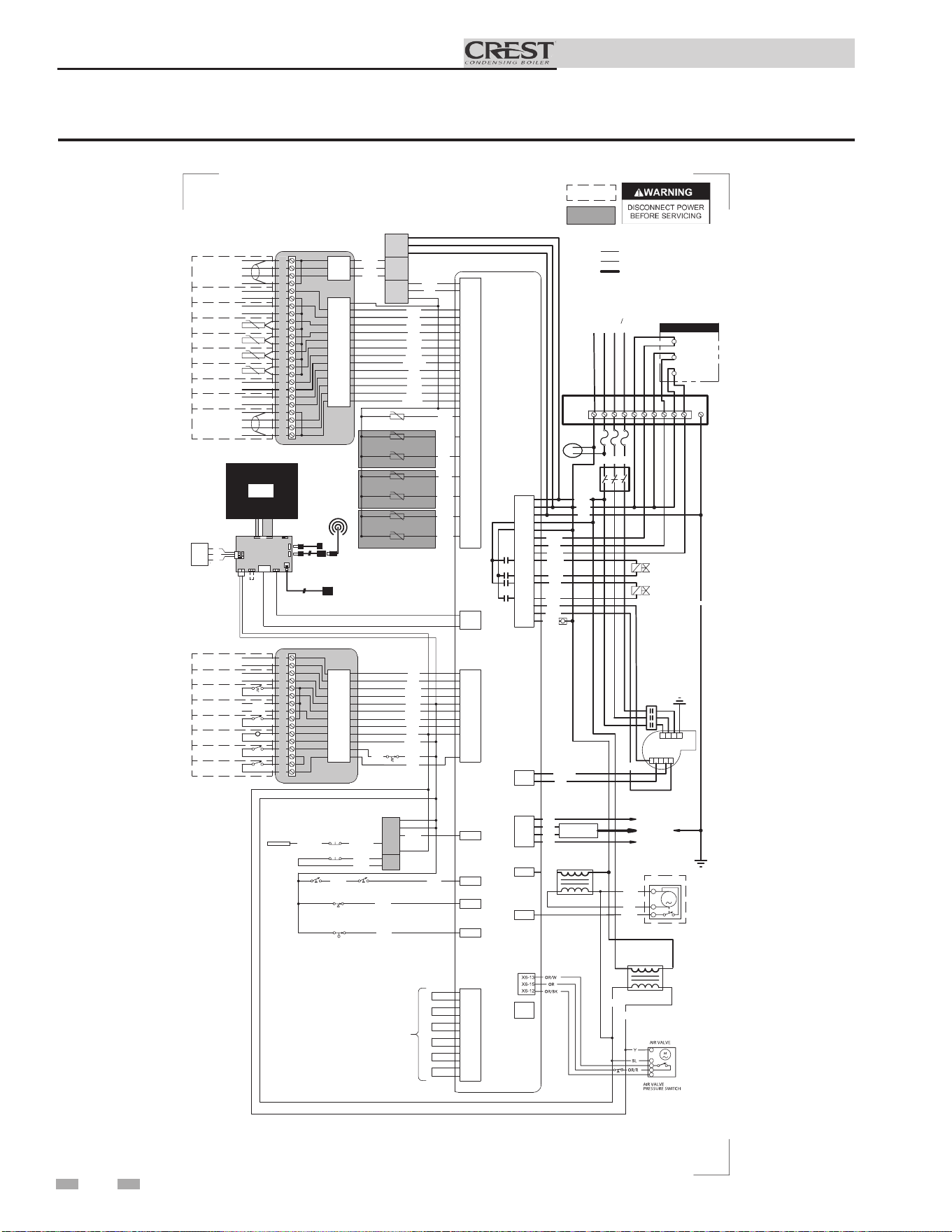
70
Installation & Operation Manual
12 Diagrams (continued)
Figure 12-4 Wiring Diagram_2501 - 3501 Models
-T
-T
-T
-T
-T
-T
-T
M
1
2
3
Notes:
1. All wiring must be installed in accordance with: local, state, provincial and national code requirements per either N.E.C. in USA or C.S.A. in Canada.
2. If any original equipment wire as supplied with the appliance must be replaced, it must be replaced with wire having same wire gauge (AWG) and rated for a
minimum of 105°C. Exceptions: Replacement high vo ltage spark lead and shielded cables must be purchased from the factory. Use of a non-approved spark lead
or shielded cables can lead to operational problems which could result in non-repairable damage to the integrated controller or other components.
3. Actual connector block locations may vary from those shown on diagrams. Refer to actual components for proper connector block locations when using
diagrams to troubleshoot unit.
BOX DEPICTS
OPTIONAL ITEMS
BOX DEPICTS
DUAL SENSOR
SINGLE HOUSING
1
2
3
4
5
6
7
8
9
10
11
12
13
14
15
16
CN1-12
CN1-5
CN1-10
CN1-11
CN1-6
CN1-9
CN1-8
CN1-7
CN1-1
CN1-2
CN1-3
CN1-4
17
CN3-6
CN6-2
CN3-7
CN3-14
CN6-1
CN3-13
CN3-12
CN3-11
CN3-10
CN3-9
CN3-8
CN6-3
18
19
20
21
22
23
24
25
26
27
28
29
30
31
32
33
34
35
36
37
38
39
40
CN3-1
CN3-2
CN3-5
CN3-3
X3-2
X3-4
X6-1
X6-11
X3-1
X6-2
X6-14
X6-10
X6-13
X6-4
X3-3
X7-8
X7-7
X8-14
X8-13
X8-12
X8-11
X8-15
X8-5
X8-6
X8-16
X8-7
X8-17
X8-18
X8-1
ALARM
CONTACTS
RUN-TIME
CONTACTS
TANK
THERMOSTAT
LOUVER
PROVING
24 VAC LOUVER
RELAY COIL
AUX
SWITCH 1
AUX
SWITCH 2
SHIELD
SHIELD
A
B
BAS
OPTION
+
-
-
+
RATE
OUT
BOILER
PUMP OUT
SYSTEM RETURN
SENSOR
SYSTEM SUPPLY
SENSOR
0-10V
0-10V
TANK
SENSOR
OUTDOOR
SENSOR
+
+
-
-
0-10V
0-10V
BMS
IN
SYSTEM
PUMP IN
SHIELD
A
B
CASCADE
R
R
RO
RO
LB
KB
RB
R
Y
BL
HIGH LIMIT
SWITCH
R
R
X6-1
X6-2
X6-3
YG
R
RP
BAS
BOARD
(AS APPLICABLE)
LB
R
LB
R
RB
W
RO
W/RO
P
W
LB
KB
KB/Y
J3-5
J3-4
J3-6
LWCO
BOARD
J3-3
J3-2
J2-1
J2-2
X6-3
RO
KB/RO
KB/RO
TEST
SWITCH
LWCO
PROBE
RO
RO
LWCO RESET
X6-5
GPS1 GPS2
RB
RO
X13-1
BLOCKED FLUE
SWITCH
RP
X6-6
BLOCKED DRAIN
SWITCH
KB
ENABLE
X8-3
X8-8
X8-2
X8-4
X8-9
X7-1
X7-5
INLET SENSOR
OUTLET SENSOR (S9)
OUTLET SENSOR (S1)
FLUE SENSOR
FLUE SENSOR (S10)
PRE-MIX SENSOR 1 (S11)
PRE-MIX SENSOR 1 (S13)
R
W
X4-1
X4-2
X4-3
X8-20
X8-10
X5-8
X5-7
X5-3
X5-9
X5-2
X5-4
X5-10
X5-5
X5-41
X5-6
X5-12
X5-1
"X5"
BLOCK WIRING
IS MODEL
DEPENDANT
KB
T
LB
W/R
R
W
YG
YG
RB
X10-1
X1-3
X10-4
X1-1
X1-12
X1-2
X1-4
X10-2
X10-5
X10-3
X10-6
X1-6
ON/OFF
SWITCH
GND
GAS VALVE
(SMALL)
GAS VALVE
(LARGE)
KB
W
RP
T
RO
RO
LB
R
LB
X6-18
X6-8
X1-8
G
X6-9
X6-17
BLOWER
KB
YG
W
T
NG
R/W
BK/W
X2-3
X1-7
X1-10
X1-5
FLAME SENSE 2
FLAME SENSE 1
SPARK
GENERATOR
SPARK ROD
X2-5
FLUE DAMPER
TRANSFORMER
X13-4
FLUE DAMPER
24V
TRANSFORMER
LB
R
R
R
P
KB
LB
Y
RO
BL
Y
BK
X1-2
X1-3
X1-1
INTEGRATED CONTROL
LARGE CONNECTION BOARD
SMALL CONNECTION BOARD
JUNCTION
BOX
X11
X4
USB
INTERFACE
BOILER PUMP
CONTACTOR
SYSTEM PUMP
CONTACTOR
DHW PUMP
CONTACTOR
HIGH VOLTAGE
LOW VOLTAGE
120 VAC
1.5A EACH MAX
WIRING DIAGRAM
100303303 REV B
1R
R
BL
1R
L1
L2
L3
208V 3
N
231
1
2
4
5
3
4
CN3-4
E
GND
LG CON BRD
WIFI
DONGLE
SW1
J2
8
43
J9
J17
J23
J12
J11
Y
J8
USB CABLE
OPTIONAL USB/WIFI
EXTENSION CABLE
J10
LCD
DISPLAY
BL
R
J6
J7
COMMUNICATION
CONTROL BOARD
OPTIONAL
ETHERNET CABLE
PR
GY
24V
SHIELD
CN6-3
CN6-1
CN6-2
BAS
R
SERVICE
OUTLET
SHIELDED CABLE FROM X4
TO J12 OR J23 AS APPLICABLE
0
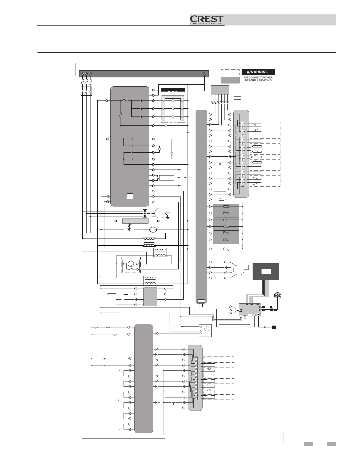
71
Installation & Operation Manual
12 Diagrams
Figure 12-5 Ladder Diagram_4001 - 5001 Models
JUNCTION BOX
TERMINAL STRIP
480V 3 SUPPLY
INTEGRATED CONTROL
ON/OFF
SWITCH
F2
3.15 A
F4
5.0 A
SYSTEM PUMP
RELAY
BOILER PUMP
RELAY
DHW PUMP
RELAY
X1-1
X1-2
X1-4
X1-8
BLOWER
CONTACTOR
SMALL GAS
VALVE RELAY
LARGE GAS
VALVE RELAY
X1-6
X10-1 X10-2
X10-3
SMALL GAS
VALVE RELAY
LARGE GAS
VALVE RELAY
X10-6
X10-5
X10-4
GAS
VALVE
(LARGE)
GAS
VALVE
(SMALL)
TERMINAL STRIP
SYSTEM PUMP
CONTACTOR
BOILER PUMP
CONTACTOR
DHW PUMP
CONTACTOR
BLOWER
CONTACTOR
BLOWER
X6-10
X13-4
X6-1
X2-5
BAS
(AS APPLICABLE)
X1-1 X1-2
X1-3
FLUE DAMPER
TRANSFORMER
M
1 2
3
24V
TRANSFORMER
FLUE DAMPER
X6-3
X1-12
X1-3
LWCO
BOARD
TEST
SWITCH
LWCO
PROBE
LWCO RESET
J3-6
J3-3
J2-1
J2-2
J3-5
J3-2
J3-4
OPTIONAL
ETHERNET CABLE
X1-3
X1-7
X1-10
X2-5
FLAME
SENSE 1
FLAME
SENSE 2
SPARK
GENERATOR
SPARK
ROD
17
18
19
20
21
22
23
24
25
26
27
28
29
30
31
32
33
34
35
36
37
38
39
40
SHIELD
SHIELD
A
B
BAS
OPTION
+
-
-
+
RATE
OUT
BOILER
PUMP OUT
SYSTEM RETURN
SENSOR
SYSTEM SUPPLY
SENSOR
0-10V
0-10V
TANK
SENSOR
OUTDOOR
SENSOR
+
+
-
-
0-10V
0-10V
BMS
IN
SYSTEM
PUMP IN
SHIELD
SHIELD
A
B
CASCADE
LARGE
CONNECTION BOARD
CN6-1
CN3-6
CN3-7
CN3-14
CN3-13
CN3-11
CN3-9
CN3-8
CN3-1
CN3-2
CN3-3
CN3-4
CN6-2
CN6-3
CN3-10
CN3-12
X4-1
X4-2
X4-3
X6-3
X6-1
X6-2
X8-20
X8-10
X7-8
X8-13
X8-14
X8-12
INTEGRATED
CONTROL
X8-5
X8-15
X7-7
X8-11
X8-6
X8-16
X8-7
X8-17
X8-18
-T
-T
-T
-T
-T
-T
-T
INLET SENSOR
OUTLET SENSOR (S9)
OUTLET SENSOR (S1)
FLUE SENSOR
FLUE SENSOR (S10)
PRE-MIX SENSOR 1 (S11)
PRE-MIX SENSOR 1 (S13)
X8-3
X8-8
X8-2
X8-4
X8-9
X7-1
X7-5
GROUND
X6-18
X6-9
X6-17
X6-8
1
4
2
5
BLOWER
E
GND
1.5A EACH MAX
X11
WIFI
DONGLE
X4
BOX DEPICTS
OPTIONAL ITEMS
BOX DEPICTS
DUAL SENSOR
SINGLE HOUSING
HIGH VOLTAGE
LOW VOLTAGE
120 VAC
Notes:
1. All wiring must be installed in accordance with: local, state, provincial and national code requirements per either N.E.C.
in USA or C.S.A. in Canada.
2. If any original equipment wire as supplied with the appliance must be replaced, it must be replaced with wire having same
wire gauge (AWG) and rated for a minimum of 105°C. Exceptions: Replacement high voltage spark lead and
shielded
cables
must be purchased from the factory. Use of a non
-approved spark lead or
shielded
cables can lead to operational problems
which could result in non-repairable damage to the integrated controller or other components.
3. Actual connector block locations may vary from those shown on diagrams. Refer to actual components for proper
connector block locations when using diagrams to troubleshoot unit.
USB
INTERFACE
L1
L2 L3
1
2
3
4
LADDER DIAGRAM
100340486 REV B
X8-10
X8-1
CN3-4
SW1
J2
8
43
J6
J9
J17
J23
J12
J11
LG CON BRD
J8
LCD
DISPLAY
USB CABLE
OPTIONAL USB/WIFI
EXTENSION CABLE
J10
J7
BAS
CN6-1
CN6-3
24V
CN6-2
1
2
3
4
5
6
7
8
9
10
11
12
13
14
15
16
ALARM
CONTACTS
RUN-TIME
CONTACTS
TANK
THERMOSTAT
LOUVER
PROVING
24 VAC LOUVER
RELAY COIL
AUX
SWITCH 1
AUX
SWITCH 2
ENABLE
R
W
CN1-4
CN1-5
CN1-6
CN1-12
CN1-10
CN1-11
CN1-9
CN1-8
CN1-7
CN1-2
CN1-3
HIGH LIMIT
SWITCH
SMALL
CONNECTION BOARD
X13-1
X6-6
X3-3
X3-4
X3-1
X3-2
X6-11
X6-2
X6-14
INTEGRATED
CONTROL
BLOCKED FLUE
SWITCH
BLOCKED DRAIN
SWITCH
X6-4
X5-1
X5-7
X5-2
X5-8
X5-3
X5-9
X5-4
X5-10
X5-5
X5-41
X5-6
X5-12
"X5"
BLOCK WIRING
IS MODEL
DEPENDANT
CN1-1
X6-5
X6-12
GPS1 GPS2
PRESS. SWITCH
AIR VALVE
X6-13
AIR VALVE
M
480V
TRANSFORMER
X8-19
AIR VALVE POSITION
RP
SERVICE OUTLET
BAS
BOARD
(AS APPLICABLE)
SHIELDED CABLE FROM X4
TO J12 OR J23 AS APPLICABLE
O
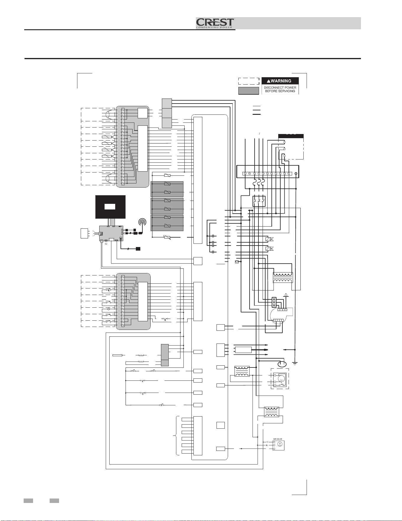
72
Installation & Operation Manual
12 Diagrams (continued)
Figure 12-6 Wiring Diagram_4001 - 5001 Models
-T
-T
-T
-T
-T
-T
-T
M
1
2
3
Notes:
1. All wiring must be installed in accordance with: local, state, provincial and national code requirements per either N.E.C. in USA or C.S.A. in Canada.
2. If any original equipment wire as supplied with the appliance must be replaced, it must be replaced with wire having same wire gauge (AWG) and rated for a
minimum of 105°C. Exceptions: Replacement high vo ltage spark lead and shielded cables must be purchased from the factory. Use of a non-approved spark
lead
or shielded cables can lead to operational problems which could result in non-repairable damage to the integrated controller or other components.
3. Actual connector block locations may vary from those shown on diagrams. Refer to actual components for proper connector block locations when using
diagrams to troubleshoot unit.
BOX DEPICTS
OPTIONAL ITEMS
BOX DEPICTS
DUAL SENSOR
SINGLE HOUSING
1
2
3
4
5
6
7
8
9
10
11
12
13
14
15
16
CN1-12
CN1-5
CN1-10
CN1-11
CN1-6
CN1-9
CN1-8
CN1-7
CN1-1
CN1-2
CN1-3
CN1-4
17
CN3-6
CN6-2
CN3-7
CN3-14
CN6-1
CN3-13
CN3-12
CN3-11
CN3-10
CN3-9
CN3-8
CN6-3
18
19
20
21
22
23
24
25
26
27
28
29
30
31
32
33
34
35
36
37
38
39
40
CN3-1
CN3-2
CN3-5
CN3-3
X3-2
X3-4
X6-1
X6-11
X3-1
X6-2
X6-14
X6-10
X6-13
X6-4
X3-3
X7-8
X7-7
X8-14
X8-13
X8-12
X8-11
X8-15
X8-5
X8-6
X8-16
X8-7
X8-17
X8-18
X8-1
ALARM
CONTACTS
RUN-TIME
CONTACTS
TANK
THERMOSTAT
LOUVER
PROVING
24 VAC LOUVER
RELAY COIL
AUX
SWITCH 1
AUX
SWITCH 2
SHIELD
SHIELD
A
B
BAS
OPTION
+
-
-
+
RATE
OUT
BOILER
PUMP OUT
SYSTEM RETURN
SENSOR
SYSTEM SUPPLY
SENSOR
0-10V
0-10V
TANK
SENSOR
OUTDOOR
SENSOR
+
+
-
-
0-10V
0-10V
BMS
IN
SYSTEM
PUMP IN
SHIELD
A
B
CASCADE
R
R
RO
RO
LB
KB
RB
R
Y
BL
HIGH LIMIT
SWITCH
R
R
X6-1
X6-2
X6-3
YG
R
RP
LB
R
LB
R
RB
W
RO
W/RO
P
W
LB
KB
KB/Y
J3-5
J3-4
J3-6
LWCO
BOARD
J3-3
J3-2
J2-1
J2-2
X6-3
RO
KB/RO
KB/RO
TEST
SWITCH
LWCO
PROBE
RO
RO
LWCO RESET
X6-5
GPS1 GPS2
RB
RO
X13-1
BLOCKED FLUE
SWITCH
RP
X6-6
BLOCKED DRAIN
SWITCH
KB
ENABLE
X8-3
X8-8
X8-2
X8-4
X8-9
X7-1
X7-5
INLET SENSOR
OUTLET SENSOR (S9)
OUTLET SENSOR (S1)
FLUE SENSOR
FLUE SENSOR (S10)
PRE-MIX SENSOR 1 (S11)
PRE-MIX SENSOR 1 (S13)
R
W
X4-1
X4-2
X4-3
X8-20
X8-10
X5-8
X5-7
X5-3
X5-9
X5-2
X5-4
X5-10
X5-5
X5-41
X5-6
X5-12
X5-1
"X5"
BLOCK WIRING
IS MODEL
DEPENDANT
KB
T
LB
W/R
R
W
YG
YG
RB
GND
GAS VALVE
(SMALL)
GAS VALVE
(LARGE)
KB
W
RO
LB
R
LB
G
X6-9
X6-17
BLOWER
KB
YG
W
T
NG
R/W
BK/W
X2-3
X1-7
X1-10
X1-5
FLAME SENSE 2
FLAME SENSE 1
SPARK
GENERATOR
SPARK ROD
X2-5
FLUE DAMPER
TRANSFORMER
X13-4
FLUE DAMPER
24V
TRANSFORMER
LB
R
R
R
P
KB
LB
Y
RO
BL
Y
X1-2
X1-3
X1-1
INTEGRATED CONTROL
LARGE CONNECTION BOARD
SMALL CONNECTION BOARD
X11
X4
USB
INTERFACE
HIGH VOLTAGE
LOW VOLTAGE
120 VAC
WIRING DIAGRAM
100340388 REV A
1R
1R
2 31
1
2
4
5
3
4
CN3-4
E
GND
LG CON BRD
WIFI
DONGLE
SW1
J2
8
43
J9
J17
J23
J12
J11
Y
J8
USB CABLE
OPTIONAL USB/WIFI
EXTENSION CABLE
J10
LCD
DISPLAY
BL
R
J6
J7
COMMUNICATION
CONTROL BOARD
OPTIONAL
ETHERNET CABLE
PR
GY
24V
SHIELD
CN6-3
CN6-1
CN6-2
BAS
R
ON/OFF
SWITCH
BK
JUNCTION
BOX
BOILER PUMP
CONTACTOR
SYSTEM PUMP
CONTACTOR
DHW PUMP
CONTACTOR
1.5A EACH MAX
R
L1
L2
L3
G
BL
480V
TRANSFORMER
X10-1
X1-3
X10-4
X1-1
X1-12
X1-2
X1-4
X10-2
X10-5
X10-3
X10-6
X1-6
X6-18
X6-8
X1-8
RO
T
RP
AIR VALVE
PRESSURE SWITCH
O/BK
X6-12
X6-13
W
O/W
X8-19
AIR VALVE POSITION
PU
RP
SERVICE
OUTLET
BAS
BOARD
(AS APPLICABLE)
SHIELDED CABLE FROM X4
TO J12 OR J23 AS APPLICABLE
480V 30
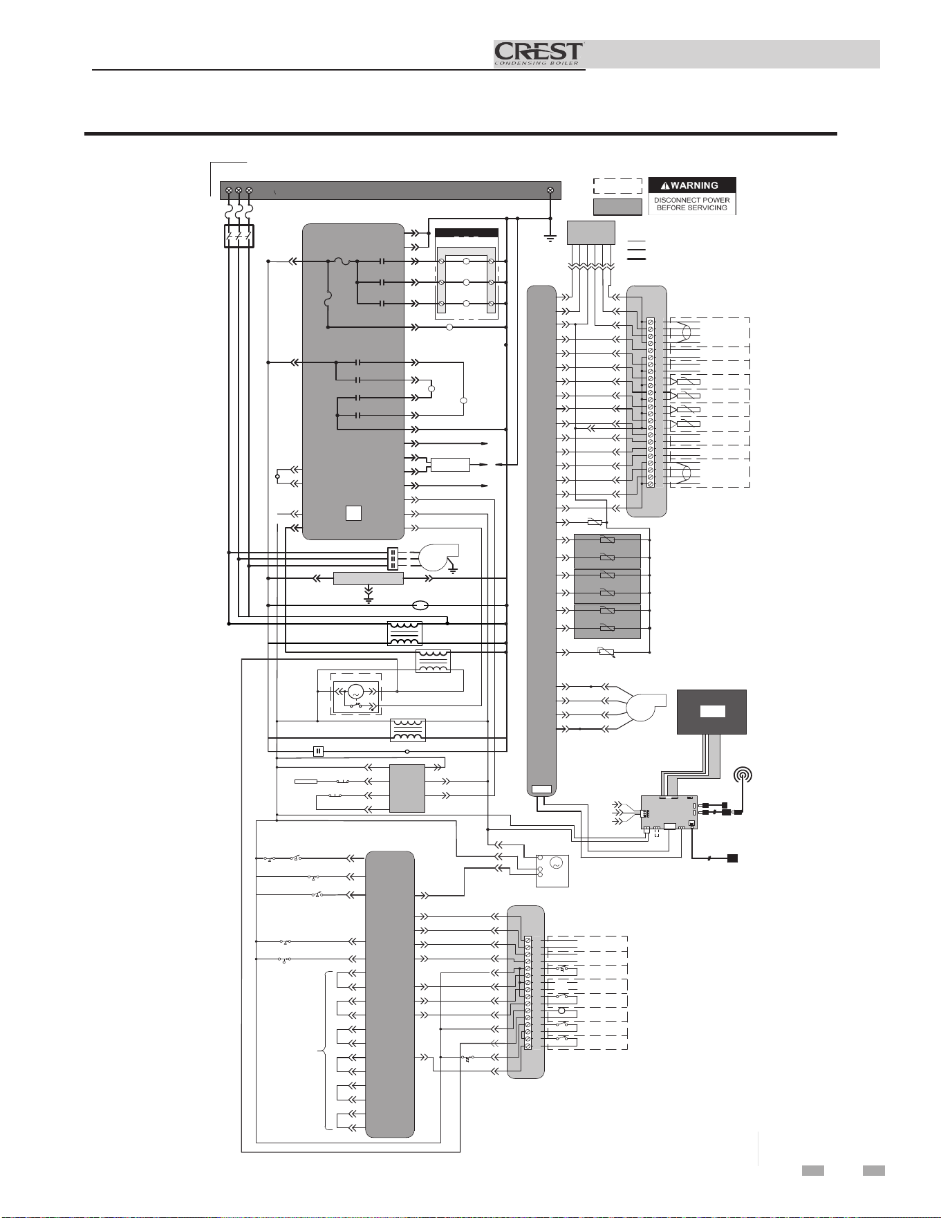
Installation & Operation Manual
12 Diagrams (continued)
Figure 12-7 Ladder Diagram_6001 Model
73
JUNCTION BOX
TERMINAL STRIP
480V 3 SUPPLY
INTEGRATED CONTROL
ON/OFF
SWITCH
F2
3.15 A
F4
5.0 A
SYSTEM PUMP
RELAY
BOILER PUMP
RELAY
DHW PUMP
RELAY
X1-1
X1-2
X1-4
X1-8
CONTACTOR
SMALL GAS
VALVE RELAY
LARGE GAS
VALVE RELAY
X1-6
X10-1 X10-2
X10-3
SMALL GAS
VALVE RELAY
LARGE GAS
VALVE RELAY
X10-6
X10-5
X10-4
GAS
VALVE
(LARGE)
GAS
VALVE
(SMALL)
TERMINAL STRIP
SYSTEM PUMP
CONTACTOR
BOILER PUMP
CONTACTOR
DHW PUMP
CONTACTOR
BLOWER
CONTACTOR
BLOWER
X6-10
X13-4
X6-1
X2-5
BAS
(AS APPLICABLE)
X1-1 X1-2
X1-3
FLUE DAMPER
TRANSFORMER
M
1 2
3
24V
TRANSFORMER
FLUE DAMPER
X6-3
X1-12
X1-3
LWCO
BOARD
TEST
SWITCH
LWCO
PROBE
LWCO RESET
J3-6
J3-3
J2-1
J2-2
J3-5
J3-2
J3-4
OPTIONAL
ETHERNET CABLE
X1-3
X1-7
X1-10
X2-5
FLAME
SENSE 1
FLAME
SENSE 2
SPARK
GENERATOR
SPARK
ROD
17
18
19
20
21
22
23
24
25
26
27
28
29
30
31
32
33
34
35
36
37
38
39
40
SHIELD
SHIELD
A
B
BAS
OPTION
+
-
-
+
RATE
OUT
BOILER
PUMP OUT
SYSTEM RETURN
SENSOR
SYSTEM SUPPLY
SENSOR
0-10V
0-10V
TANK
SENSOR
OUTDOOR
SENSOR
+
+
-
-
0-10V
0-10V
BMS
IN
SYSTEM
PUMP IN
SHIELD
SHIELD
A
B
CASCADE
LARGE
CONNECTION BOARD
CN6-1
CN3-6
CN3-7
CN3-14
CN3-13
CN3-11
CN3-9
CN3-8
CN3-1
CN3-2
CN3-3
CN3-4
CN6-2
CN6-3
CN3-10
CN3-12
X4-1
X4-2
X4-3
X6-3
X6-1
X6-2
X8-20
X8-10
X7-8
X8-13
X8-14
X8-12
INTEGRATED
CONTROL
X8-5
X8-15
X7-7
X8-11
X8-6
X8-16
X8-7
X8-17
X8-18
-T
-T
-T
-T
-T
-T
-T
INLET SENSOR
OUTLET SENSOR (S9)
OUTLET SENSOR (S1)
FLUE SENSOR
FLUE SENSOR (S10)
PRE-MIX SENSOR 1 (S11)
PRE-MIX SENSOR 1 (S13)
X8-3
X8-8
X8-2
X8-4
X8-9
X7-1
X7-5
GROUND
X6-18
X6-9
X6-17
X6-8
1
4
2
5
BLOWER
E
GND
1.5A EACH MAX
X11
WIFI
DONGLE
X4
BOX DEPICTS
OPTIONAL ITEMS
BOX DEPICTS
DUAL SENSOR
SINGLE HOUSING
HIGH VOLTAGE
LOW VOLTAGE
120 VAC
Notes:
1. All wiring must be installed in accordance with: local, state, provincial and national code requirements per either N.E.C.
in USA or C.S.A. in Canada.
2. If any original equipment wire as supplied with the appliance must be replaced, it must be replaced with wire having same
wire gauge (AWG) and rated for a minimum of 105°C. Exceptions: Replacement high voltage spark lead and
shielded
cables
must be purchased from the factory. Use of a non
-approved spark lead or
shielded
cables can lead to operational problems
which could result in non-repairable damage to the integrated controller or other components.
3. Actual connector block locations may vary from those shown on diagrams. Refer to actual components for proper
connector block locations when using diagrams to troubleshoot unit.
USB
INTERFACE
L1
L2 L3
1
2
3
4
LADDER DIAGRAM
100340487 REV B
X8-10
X8-1
CN3-4
SW1
J2
8
43
J6
J9
J17
J23
J12
J11
LG CON BRD
J8
LCD
DISPLAY
USB CABLE
OPTIONAL USB/WIFI
EXTENSION CABLE
J10
J7
BAS
CN6-1
CN6-3
24V
CN6-2
1
2
3
4
5
6
7
8
9
10
11
12
13
14
15
16
ALARM
CONTACTS
RUN-TIME
CONTACTS
TANK
THERMOSTAT
LOUVER
PROVING
24 VAC LOUVER
RELAY COIL
AUX
SWITCH 1
AUX
SWITCH 2
ENABLE
R
W
CN1-4
CN1-5
CN1-6
CN1-12
CN1-10
CN1-11
CN1-9
CN1-8
CN1-7
CN1-2
CN1-3
HIGH LIMIT
SWITCH
SMALL
CONNECTION BOARD
X13-1
X6-6
X3-3
X3-4
X3-1
X3-2
X6-11
X6-2
X6-14
INTEGRATED
CONTROL
BLOCKED FLUE
SWITCH
BLOCKED DRAIN
SWITCH
X6-4
X5-1
X5-7
X5-2
X5-8
X5-3
X5-9
X5-4
X5-10
X5-5
X5-41
X5-6
X5-12
"X5"
BLOCK WIRING
IS MODEL
DEPENDANT
CN1-1
X6-5
X6-15
X6-12
GPS GPS2
POC
X6-13
AIR VALVE
CN-1
CN-4
CN-2
M
480V
TRANSFORMER
X6-1
X2-5
R3
P.O.C. VALVE
AIR VALVE
PRESSURE SWITCH
X8-19
R3
AIR VALVE POSITION
RP
SERVICE OUTLET
BAS
BOARD
(AS APPLICABLE)
SHIELDED CABLE FROM X4
TO J12 OR J23 AS APPLICABLE
O
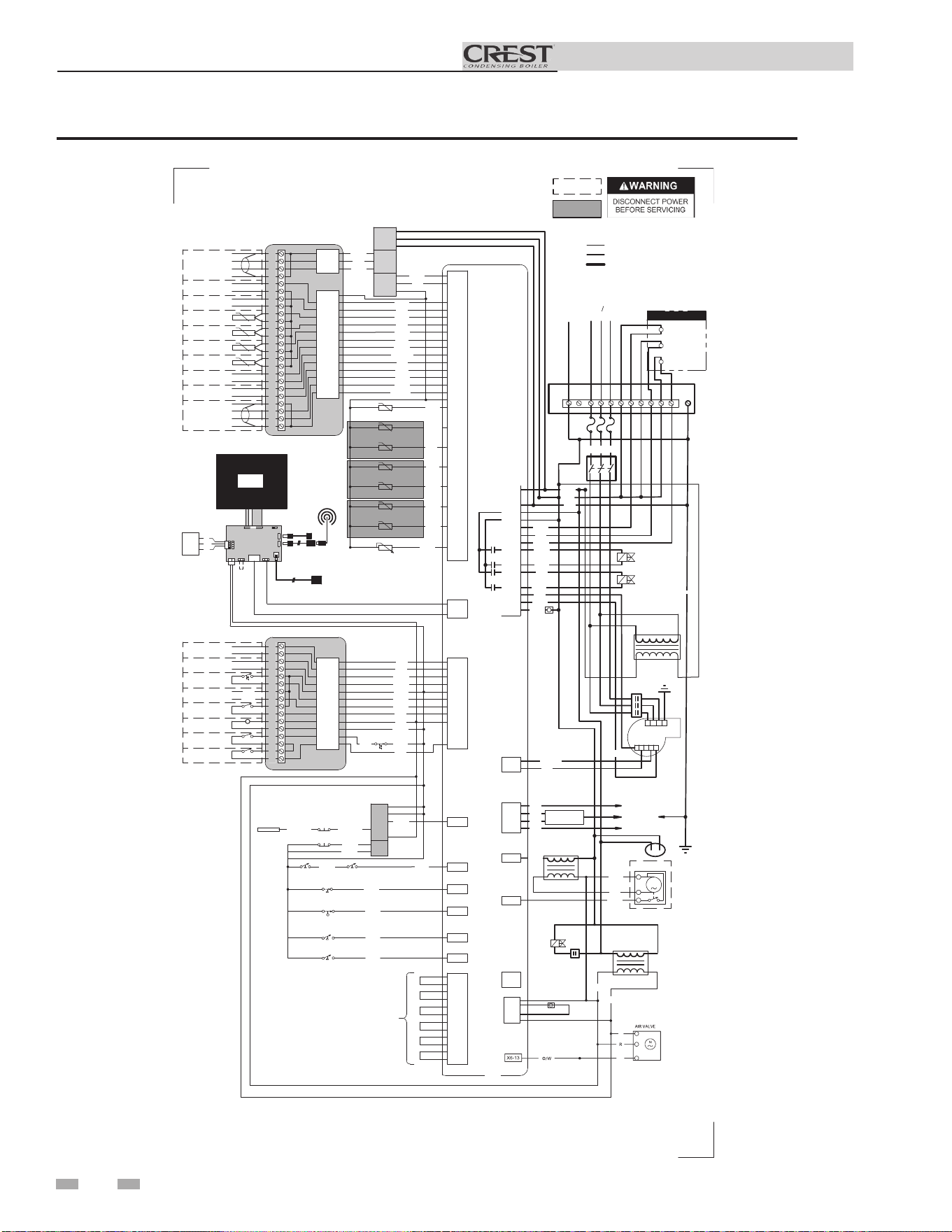
74
Installation & Operation Manual
12 Diagrams
Figure 12-8 Wiring Diagram_6001 Model
-T
-T
-T
-T
-T
-T
-T
M
1
2
3
Notes:
1. All wiring must be installed in accordance with: local, state, provincial and national code requirements per either N.E.C. in USA or C.S.A. in Canada.
2. If any original equipment wire as supplied with the appliance must be replaced, it must be replaced with wire having same wire gauge (AWG) and rated for a
minimum of 105°C. Exceptions: Replacement high vo ltage spark lead and shielded cables must be purchased from the factory. Use of a non-approved spark
lead
or shielded cables can lead to operational problems which could result in non-repairable damage to the integrated controller or other components.
3. Actual connector block locations may vary from those shown on diagrams. Refer to actual components for proper connector block locations when using
diagrams to troubleshoot unit.
BOX DEPICTS
OPTIONAL ITEMS
BOX DEPICTS
DUAL SENSOR
SINGLE HOUSING
1
2
3
4
5
6
7
8
9
10
11
12
13
14
15
16
CN1-12
CN1-5
CN1-10
CN1-11
CN1-6
CN1-9
CN1-8
CN1-7
CN1-1
CN1-2
CN1-3
CN1-4
17
CN3-6
CN6-2
CN3-7
CN3-14
CN6-1
CN3-13
CN3-12
CN3-11
CN3-10
CN3-9
CN3-8
CN6-3
18
19
20
21
22
23
24
25
26
27
28
29
30
31
32
33
34
35
36
37
38
39
40
CN3-1
CN3-2
CN3-5
CN3-3
X3-2
X3-4
X6-1
X6-11
X3-1
X6-2
X6-14
X6-10
X6-13
X6-4
X3-3
X7-8
X7-7
X8-14
X8-13
X8-12
X8-11
X8-15
X8-5
X8-6
X8-16
X8-7
X8-17
X8-18
X8-1
ALARM
CONTACTS
RUN-TIME
CONTACTS
TANK
THERMOSTAT
LOUVER
PROVING
24 VAC LOUVER
RELAY COIL
AUX
SWITCH 1
AUX
SWITCH 2
SHIELD
SHIELD
A
B
BAS
OPTION
+
-
-
+
RATE
OUT
BOILER
PUMP OUT
SYSTEM RETURN
SENSOR
SYSTEM SUPPLY
SENSOR
0-10V
0-10V
TANK
SENSOR
OUTDOOR
SENSOR
+
+
-
-
0-10V
0-10V
BMS
IN
SYSTEM
PUMP IN
SHIELD
A
B
CASCADE
R
R
RO
RO
LB
KB
RB
R
Y
BL
HIGH LIMIT
SWITCH
R
R
X6-1
X6-2
X6-3
YG
R
RP
LB
R
LB
R
RB
W
RO
W/RO
P
W
LB
KB
KB/Y
J3-5
J3-4
J3-6
LWCO
BOARD
J3-3
J3-2
J2-1
J2-2
X6-3
RO
KB/RO
KB/RO
TEST
SWITCH
LWCO
PROBE
RO
RO
LWCO RESET
X6-5
GPS1 GPS2
RB
RO
X13-1
BLOCKED FLUE
SWITCH
RP
X6-6
BLOCKED DRAIN
SWITCH
KB
ENABLE
X8-3
X8-8
X8-2
X8-4
X8-9
X7-1
X7-5
INLET SENSOR
OUTLET SENSOR (S9)
OUTLET SENSOR (S1)
FLUE SENSOR
FLUE SENSOR (S10)
PRE-MIX SENSOR 1 (S11)
PRE-MIX SENSOR 1 (S13)
R
W
X4-1
X4-2
X4-3
X8-20
X8-10
X5-8
X5-7
X5-3
X5-9
X5-2
X5-4
X5-10
X5-5
X5-41
X5-6
X5-12
X5-1
"X5"
BLOCK WIRING
IS MODEL
DEPENDANT
KB
T
LB
W/R
R
W
YG
YG
RB
GND
GAS VALVE
(SMALL)
GAS VALVE
(LARGE)
KB
W
RO
LB
R
LB
G
X6-9
X6-17
BLOWER
KB
YG
W
T
NG
R/W
BK/W
X2-3
X1-7
X1-10
X1-5
FLAME SENSE 2
FLAME SENSE 1
SPARK
GENERATOR
SPARK ROD
X2-5
FLUE DAMPER
TRANSFORMER
X13-4
FLUE DAMPER
24V
TRANSFORMER
LB
R
R
R
P
KB
LB
Y
RO
BL
Y
X1-2
X1-3
X1-1
INTEGRATED CONTROL
LARGE CONNECTION BOARD
SMALL CONNECTION BOARD
X11
X4
USB
INTERFACE
HIGH VOLTAGE
LOW VOLTAGE
120 VAC
WIRING DIAGRAM
100340502 REV A
1R
1R
2 31
1
2
4
5
3
4
CN3-4
E
GND
LG CON BRD
WIFI
DONGLE
SW1
J2
8
43
J9
J17
J23
J12
J11
Y
J8
USB CABLE
OPTIONAL USB/WIFI
EXTENSION CABLE
J10
LCD
DISPLAY
BL
R
J6
J7
COMMUNICATION
CONTROL BOARD
OPTIONAL
ETHERNET CABLE
PR
GY
24V
SHIELD
CN6-3
CN6-1
CN6-2
BAS
R
ON/OFF
SWITCH
BK
JUNCTION
BOX
BOILER PUMP
CONTACTOR
SYSTEM PUMP
CONTACTOR
DHW PUMP
CONTACTOR
1.5A EACH MAX
R
L1
L2
L3
480V 30
G
BL
480V
TRANSFORMER
X10-1
X1-3
X10-4
X1-1
X1-12
X1-2
X1-4
X10-2
X10-5
X10-3
X10-6
X1-6
X6-18
X6-8
X1-8
RO
T
RP
X12-1
X12-2
X12-5
X12-4
3R
P.O.C
VALVE
3R
RP
AIR VALVE
POSITION
X8-19
PU
X6-15
POC
BR
AIR VALVE
PRESSURE SWITCH
O/BK
X6-12
BK
W
SERVICE
OUTLET
BAS
BOARD
(AS APPLICABLE)
SHIELDED CABLE FROM X4
TO J12 OR J23 AS APPLICABLE

75
Installation & Operation Manual
Notes

Revision W (PCP #3000028279 / CN #500017755) reflects an update
to the user interface screens, wiring diagrams, and ladder diagrams.
Revision X (PCP #3000028854 / CN #500018329) reflects an update
to Figure 5-4.
Revision Y (PCP #3000029921 / CN #500019205) reflects an update
to the data in Figures 5-1A and 5-1B along with Table 5A on pages 30
and 31.
Revision AA (PCP #3000031194 / CN #500020655) reflects an update
to Tables 2B, 2C, 2G, and FIG. 2-2. This also includes the addition
of Table 2F.
Revision AB (PCP #3000033465 / CN #500022172) reflects the
addition of the neutral wiring reference on page 41 along with the
addition of the combustion measurement port on pages 4 and 5.
Revision AC (PCP #3000035711 / CN #500024133) reflects an update
to the Ratings Table and Table 6A.
Revision AD (PCP #3000036331 / CN #500024646) reflects an update
from 7” to 8” pipe in the hydronic piping charts.
Revision AE (PCP #3000037348 / CN #500025601) reflects an update
to the ICC part numbers in Table 2A-2.
Revision AF (PCP #3000038943 / CN #500027005) reflects an update
to the common header tables on pages 34 and 36.
Revision AG (PCP #3000040404 / CN #500028531) reflects an update
to the propane minimum gas pressure.
Revision AH (PCP #3000042364 / CN #500030203) reflects an update
to the wiring and ladder diagrams, line voltage field wiring connections
image on page 41 and high altitude changes.
Revision AJ (PCP #3000047882 / CN #500035724) reflects an update
to the Z-Flex adapters listed on General Venting Table 2A-2 on page
17.
Revision AK (PCP #3000046794 / CN #500034183) reflects an update
to the verbiage in the note in Table 2A-2 Approved Stainless Steel
Terminations and Adapters - Category IV on page 17.
Revision AL (PCP #300049089 / CN #500036206) reflects changes to
the gas check instructions on page 39 and a new image for Fig. 6-4
on page 40.
Revision AM (PCP #300051739 / CN #500038610) reflects the addition
of DuraVent information to table 2A-2 on pages 16 and 17.
Revision AN (PCP #3000054410 / CN #500041125) reflects an update
to the warnings on page 7.
Revision AP (PCP #3000054384 / CN #500041091) reflects an update
to table 2D.
Revision AR (PCP #3000056994 / #500043275) reflects updated
torque requirements on pages 65 and 66.
Revision AT (PCP #3000057732 / #500043895) reflects the addition of
a carbon monoxide warning on page 3.
Revision AU (PCP #3000060567 . CN #500046569) reflects an update
to table 2H.
Revision AV (PCP #3000062745 / CN #500048580) reflects updates to
page 30 and pages 47-48.
Revision AW (PCP #3000062176 / CN #500048407) reflects updated
ladder diagrams.
Revision AX (PCP #3000063806 / CN #500049657) reflects water
quality updates throughout.
Revision AY (PCP #3000065587 / CN #500051364) reflects additional
cautions and notices to pages 32, 36, and 37.
Revision BA (PCP #3000069081 / CN #500054642) reflects updates to
the caution on pages 36 & 37.
100208043_2000004587_Rev BA
11/25
Revision Notes: Revision A (ECO #C17106) initial release.
Revision B (ECO C17419) reflects the addition of the large Crest
models (1501 - 2001).
Revision C (Change #500000695) reflects the addition of ICC
venting options on page 17 (R06799), add PVC to SS adapter and 6”
starter piece on page 20 (R08066), along with edits made to the Gas
Connections Section, and the addition of the California contaminant
warning on page 3 (R07228).
Revision D (Change #500000938) reflects the removal of the
balancing valves notice on page 34.
Revision E (Change #500001029) reflects the addition of the Crest
CON•X•US Interface, along with the addition of the re-spark ignition
option.
Revision F (PCP# 3000002544 / CN# 500002701) reflects an update
to step 10 in Sequence of Operation on page 57.
Revision G (PCP# 3000001665 / CN# 500001821) reflects the
addition of Step 4 under the Common Venting section on page 19.
SAP part numbers have been updated.
Revision H (PCP# 3000003037 / CN# 500003264) reflects an
update to Figures 5-4 & 5-5 on pages 33 & 34.
Revision J (PCP# 3000005648 / CN# 500006460) reflects an update
to Figures 3-3 and 3-4 on page 23 and Figure 4-5 on page 27.
Revision K (PCP# 3000004438 / CN# 500005574) reflects an
update to the flue temperatures on page 54.
Revision L (PCP# 3000007531 / CN# 500007598) reflects changes
made to water chemistry information on pages 3, 7, 17, 21, 28-34,
44-45, and 59.
Revision M (PCP# 3000006133 / CN# 500007549) reflects the
addition of a PVC-DWV vent fitting in Table 2E on page 20.
Revision N (PCP# 3000009267 / CN# 500009031) reflects an
update to the pH Level range on page 44.
Revision P (PCP# 3000009150 / CN# 500008822) reflects edits
made to the vent terminations on pages 23 and 27 along with the
removal of 48” MAX termination references on pages 24, 25 and 27.
Revision R (PCP #3000010423 / CN #500010150) reflects an
update to the neutralizer information on page 43.
Revision T (PCP #3000021559 / CN #500011827) reflects the
addition of the 6” vent option along with changes made to the Btu
inputs on page 6.
Revision U (PCP# 3000025102 / CN# 500014948) reflects the
addition of Models 2501 - 6001.
Revision V (PCP #3000027116 / CN #500016865) reflects the
addition of the 110 and 111 series.