1
Smart Climate Controller (SLR) (Wall Mount)
FCC ID: 2APQIITAFSRSMT
IC: 30370-ITAFSRSMT
UL Part Numbers: IT-AF-SLR-SMT
IT-AF-SLR-SMT
Overview
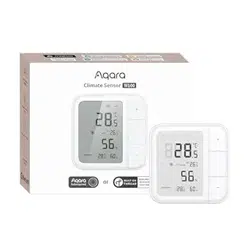
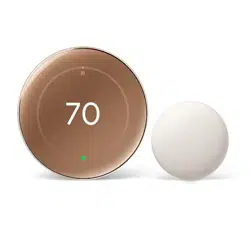
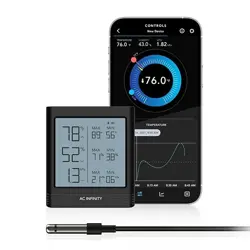
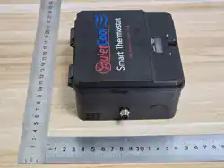
This document summarizes the introduction of the climate controller thermostat IT-AF-SLR-SMT
(Fig.1). IT-AF-SLR-SMT is a solar powered, environmentally friendly, and energy-saving smart
product for fans that help save on HVAC systems. Powered by solar energy and the power grid, with
priority given to utilizing solar energy. IT-AF-SLR-SMT enables users to remotely control multiple
different models of solar fans through Android & iOS apps via Bluetooth distribution network (Fig.2).
(Fig.1)
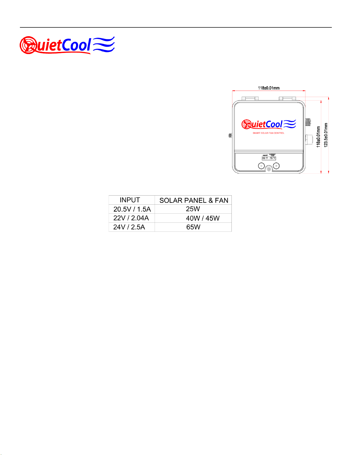
Specifications
(Fig. 2)
Warning:
- Disconnect power at the circuit breaker
before installing or servicing
- Use wires rated at least 105 ℃ – copper
only
- Installation/wiring must be in accordance
with national and local code regulations
- Keep the enclosure cover closed at all
times when not servicing.
- Cover all unused wires with a wire
connector
FCC Regulations
FCC Supplier’s Declaration of Conformity
Product Name: Smart Climate Controller (SLR)
Model number: IT-AF-SLR-SMT
FCC ID: 2APQIITAFSRSMT
IC: 30370-ITAFSRSMT
UL Part Number: IT-AF-SLR-SMT
Suppliers Name: QC Manufacturing Inc.
Suppliers Address (USA): 26040 Ynez rd. Temecula, California 92591, United States
Suppliers Website: www.QuietCoolSystems.com
2
ISED Warning statements in User Manual
This device contains licence-exempt transmitter(s)/receiver(s) that comply with Innovation, Science and Economic Development
Canada’s licence-exempt RSS(s). Operation is subject to the following two conditions:
1.This device may not cause interference.
2.This device must accept any interference, including interference that may cause undesired operation of the device.
L’émetteur/récepteur exempt de licence contenu dans le présent appareil est conforme aux CNR d’Innovation, Sciences et
Développement économique Canada applicables aux appareils radio exempts de licence. L’exploitation est autorisée aux
deux conditions suivantes : (1)L’appareil ne doit pas produire de brouillage;(2)L’appareil doit accepter tout brouillage
radioélectrique subi, même si le brouillage est susceptible d’en compromettre le fonctionnement.
This equipment complies with IC RSS-102 radiation exposure limits set forth for an uncontrolled environment. This
equipment should be installed and operated with a minimum distance of 20cm between the radiator and any part of your
body.
Pour se conformer aux exigences de conformit
é
CNR 102 RF exposition, une distance de s
é
paration d'au moins 20 cm
doit
ê
tre maintenue entre l'antenne de cet appareil ettoutes les personnes.
FCC Warning statements in User Manual
This device complies with Part 15 of the FCC Rules. Operation is subject to the following two conditions: (1)
this device may not cause harmful interference, and (2) this device must accept any interference received,
including interference that may cause undesired operation.
Caution: The user is cautioned that changes or modifications not expressly approved by the party responsible
for compliance could void the user's authority to operate the equipment.
Note: This equipment has been tested and found to comply with the limits for a Class B digital device, pursuant
to part 15 of the FCC Rules. These limits are designed to provide reasonable protection against harmful
interference in a residential installation. This equipment generates uses and can radiate radio frequency
energy and, if not installed and used in accordance with the instructions, may cause harmful interference to
radio communications. However, there is no guarantee that interference will not occur in a particular
installation. If this equipment does cause harmful interference to radio or television reception, which can be
determined by turning the equipment off and on, the user is encouraged to try to correct the interference by
one or more of the following measures:
—Reorient or relocate the receiving antenna.
—Increase the separation between the equipment and receiver.
—Connect the equipment into an outlet on a circuit different from that to which the receiver is connected.
—Consult the dealer or an experienced radio/TV technician for help.
FCC RF Radiation Exposure Statement:
This equipment complies with FCC radiation exposure limits set forth for an uncontrolled environment. This equipment should
be installed and operated with a minimum distance of 20cm between the radiator and any part of your body.
3
Installation Instruction
Ensure to turn off the main power of the adapter before wiring. Installation can only be completed by qualified personnel.
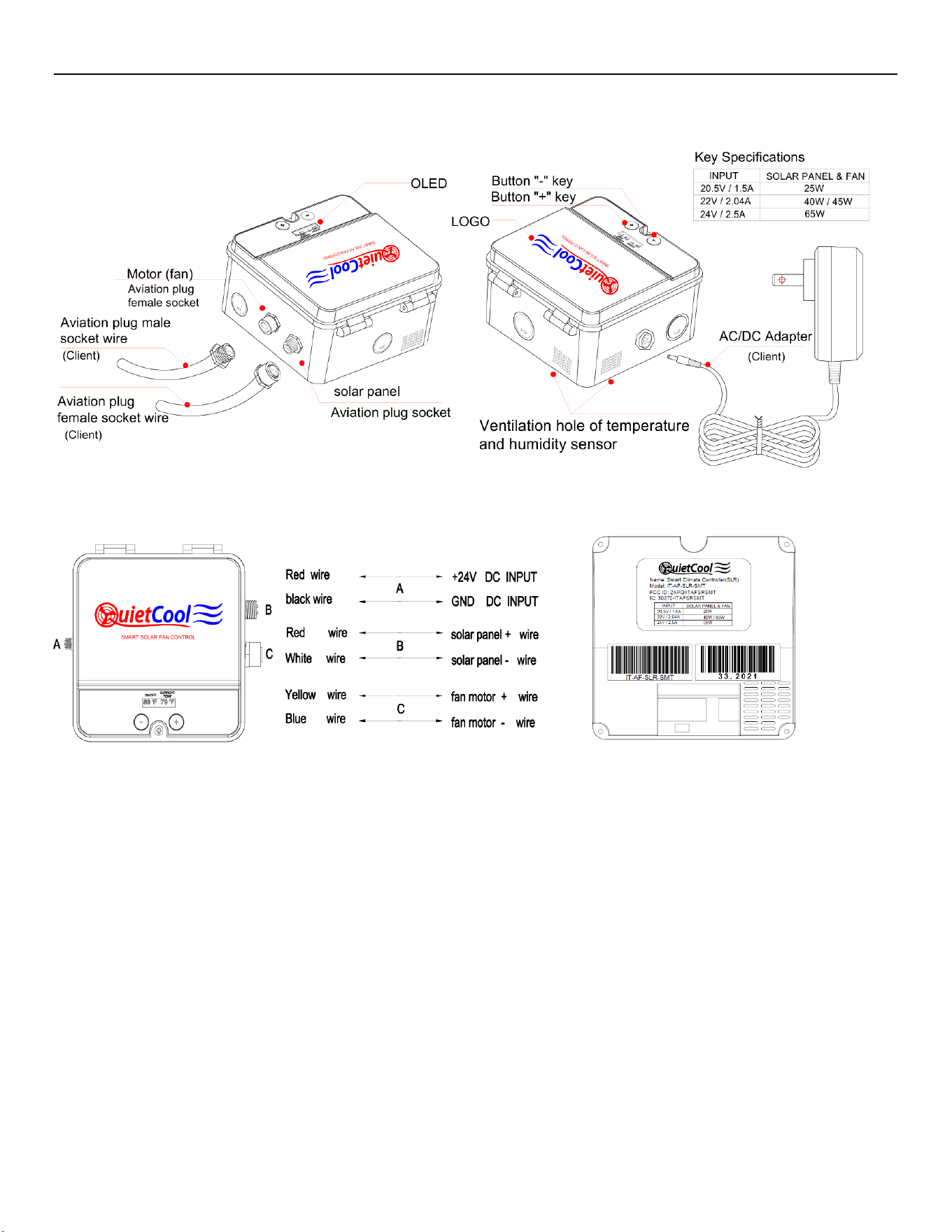
Install the adapter, controller, solar panel, and fan according to the product specifications (Fig.2) and wiring diagram (Fig.3).
(Fig.3)
Unscrew the screws securing the cover and flip it upwards as shown in Fig.4.
Once the cover is open, We can see the label as shown in Fig.5
(Fig. 4) (Fig. 5) Product Label
Color specifications of wires inside the control box (Fig. 4 ) .
The A/B/C ports of the control box are all aviation plug interfaces.
Control box A, connected to the DC power output terminal of the adapter.
Control box B connects to the solar panel.
Control box C connects to the fan.
Once wiring is completed, close the cover and tighten the screw.
Caution: When inserting the aviation plug into the male/female socket, the positive/negative terminals should not be reversed.
Note: When using an aviation plug, the male and female terminals must be inserted together, and the positive and negative terminals must not be
reversed.
4
Panel operation for thermostat
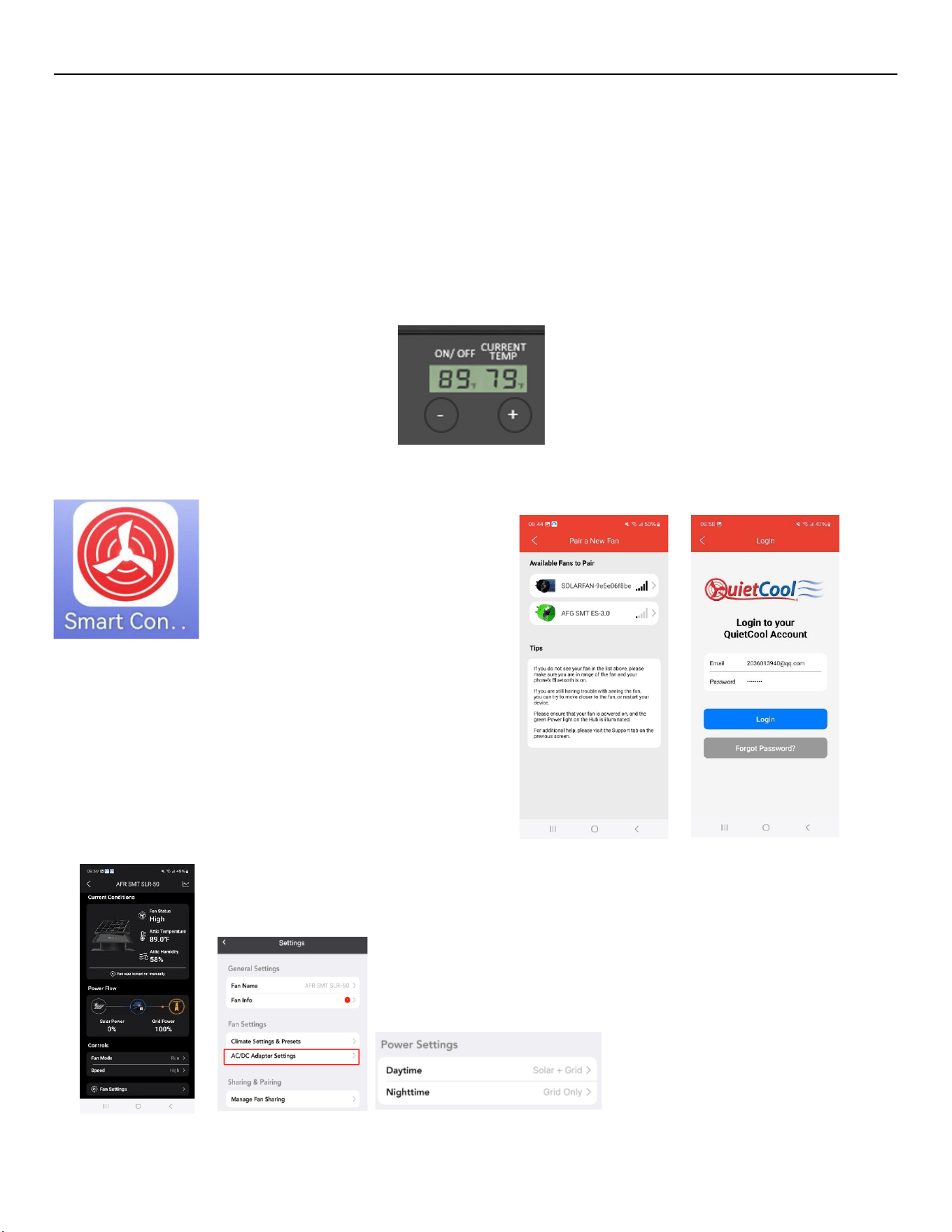
(1) After powering on, first reset the distribution network operation, that is, reset the switch (reset Bluetooth connection):
Press the "+" and "-" buttons on the panel simultaneously for 5 seconds, and the screen will display "Reset...",
When successful, display " " and restore the initial state value (Fig. 6 ).
(2) The default display on the left side of the screen is 80 ℉this temperature represent the turn on point for the unit/ thermostat, and the current actual
temperature value ℉ is displayed on the right side (Fig.6).
Press the "-" key on the panel, the number on the left will change to 75 ℉, and then press the "+" key to return the number to 80 ℉.
Press the "+" and "-" buttons on the panel three times at the same time to switch between ℉/℃ units.
Not pressing the button for 5 consecutive minutes will turn off the screen, and pressing the button again will turn on the screen.
(Fig. 6)
APP Operation
(Fig. 7)
1. Click on the icon of the installed APP software (Fig. 7 ).
2. Then follow the prompts step by step.
3.Login to your QuietCool Account (Fig. 8 ).
4. Pair a NEW Fan via Bluetooth (Fig. 9 ) .
5. Follow the prompts to enter the control interface (Fig. 10).
6. Click “Fan Setting” to enter (Fig. 11).
7. Click “AC/DC Adapter Settings” to enter the power settings. (Fig. 12).
(Fig.8) ( Fig.9)
( Fig.10) ( Fig.11) (Fig. 12 )
5
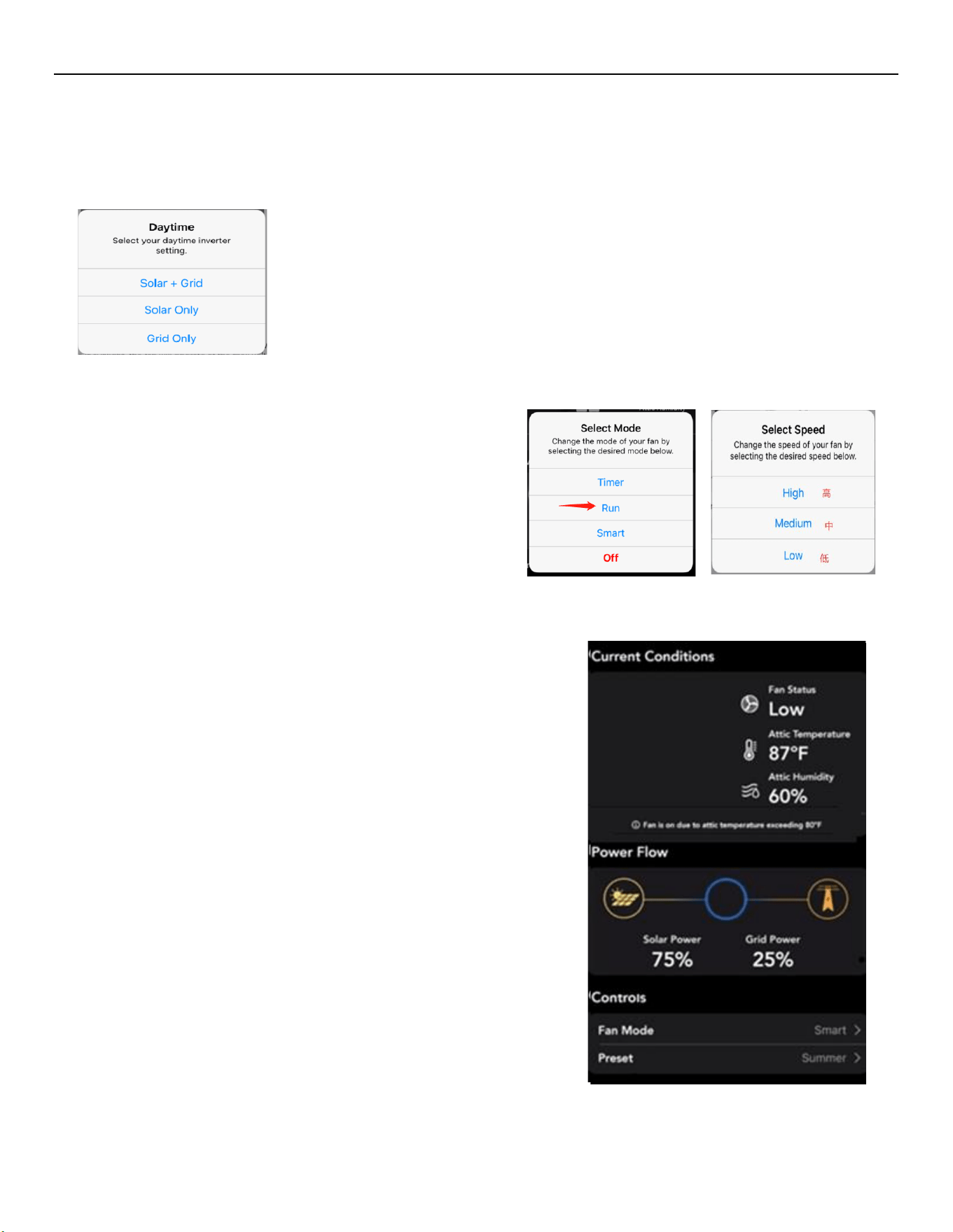
The power settings are divided into daytime and nighttime power settings (Figure-12).
Click “Daytime” to enter the daytime power settings (Figure-12).
During the day, the power settings interface will display the current power settings.
Clicking on it will bring up a power options pop-up window (Figure-13).
The pop-up options will show three power modes :
Mode 1. "Solar + Grid" : Solar energy + grid mode ;
Mode 2. "Solar Only" : Solar-only mode ;
(Fan speed cannot be controlled in solar mode only; the fan speed setting
is the highest setting currently supported by solar power.)
Mode 3. "Grid Only" : Grid only mode (DC power supply only);
(Figure-13)
After selecting “Grid Only” mode, return to the APP homepage control interface.
8. On the homepage, click “Fan Mode” and select “Run” (Fig. 14).
In the pop-up menu, select the fan speed setting (Figure-15).
(Figure-14) (Figure-15)
change the Nighttime power setting from "Grid Only" to "Off".
In the power settings, under Daytime power, select mode 1 , "Solar + Grid,"
from the pop-up power modes.
9.When selecting High (high-end) / Medium (medium-end) / Low (low-end) in
Figure (15). The homepage control interface of the APP will display the
proportion of solar energy and the proportion of the power grid (Figure-12).
The proportion shown in the right image is for reference only; the actual data
displayed shall prevail.
Requirements: Under the condition that the grid voltage and solar illumination
intensity remain constant, When switching between high and low settings, the
proportion of solar energy increases while the proportion of grid power
decreases to be considered acceptable.
10. Timer function: up to 12 hours of timer with an interval of 1 hour, when
high/medium/low speed is selected.
11. Power-off memory function: If the fan is turned on and then loses power, the
6
fan will remember the power-off memory function when the power is turned on again.
Start the corresponding setting (except for timer mode) that was set before the power failure.
12.Long distance: The mobile phone and the controller can connect normally in open conditions between 10 and 20 meters.
13. Temperature resistance test: Place the controller in a programmable constant temperature chamber, and set the temperature to
-20℃ ~ +80℃. Requirements: The load fan must be able to turn on and off normally to be considered qualified (Note: Solar
panels are not required). Connect only to wind turbine load, grid mode only, control level, on and off).
14.Return to the APP homepage control interface, click "Fan Mode", and then click on the top (Figure-14) (Figure-16).
Select " Off" to turn off the fan.
15. Prevent self-starting: repeatedly plug and unplug the power adapter plug (10 times) to ensure that the fan will not start on its
own.
16.Reset factory settings: Switch reset. Press and hold the "+" and "-" buttons on the panel for 5 seconds. The screen will display
"Re set..." . If successful, it will display " ✓", restoring the initial state.