Installation Instructions
& Owner's Manual
Commercial
Water Soeners
C43 & C47 Series 1-2” Soeners and Conditioners
aosmith.com/commercialwatertreatment

Quick Reference Guide
Pre-Installation Instructions ...................................................... 3
Quick Reference Guide ........................................................... 4
Bypass Valve ................................................................... 6
Initial Controller Set-Up .......................................................... 7
Operating Displays and Maintenance .............................................. 9
Troubleshooting Guide ..........................................................11
Replacement Parts .............................................................14
Installation Fitting Assemblies ...................................................31
Warranty .....................................................................33
Your A. O. Smith commercial water softeners and conditioners are precision built, high quality products. These
units will deliver conditioned water for many years to come when installed and operated properly. Please study
this manual carefully and understand the cautions and notes. This manual should be left at the installation site by
the servicing agent to use as future reference by the system owner. If you have any questions regarding your water
conditioner, contact your servicing agent.
SERVICING AGENT
PHONE NUMBER
Table of Contents
3
THE SERVICING AGENT MUST...
•Read this page and guide the installer regarding hardness, day
override, time of regeneration, service alarm, and buzzer alarm
settings prior to installation.
•Insert Servicing Dealer information on the table of contents in this
manual.
•Fill out the Model Number, Serial Number, Water Hardness, and Time
of Regen information below.
•Fill out the Model Number and Serial Number information on the
warranty page of this manual.
THE INSTALLER MUST...
•Confirm installer programming settings are correct.
•Read Operating Displays and Maintenance section.
•Set the time of day
•Read Power Loss and Error Display section.
•Ensure that system and installation are in compliance with all state and
local laws and regulations
The manufacturer has preset the water treatment unit’s sequence of cycles, cycle times, salt dose, exchange capacity and salt dose refill time.
PRODUCT INFORMATION
Servicing Agent must fi ll out this informa on prior to unit installa on
INSTALLATION DATE
MODEL NUMBER
*SERIAL NUMBER
WATER HARDNESS
TIME OF REGENERATION
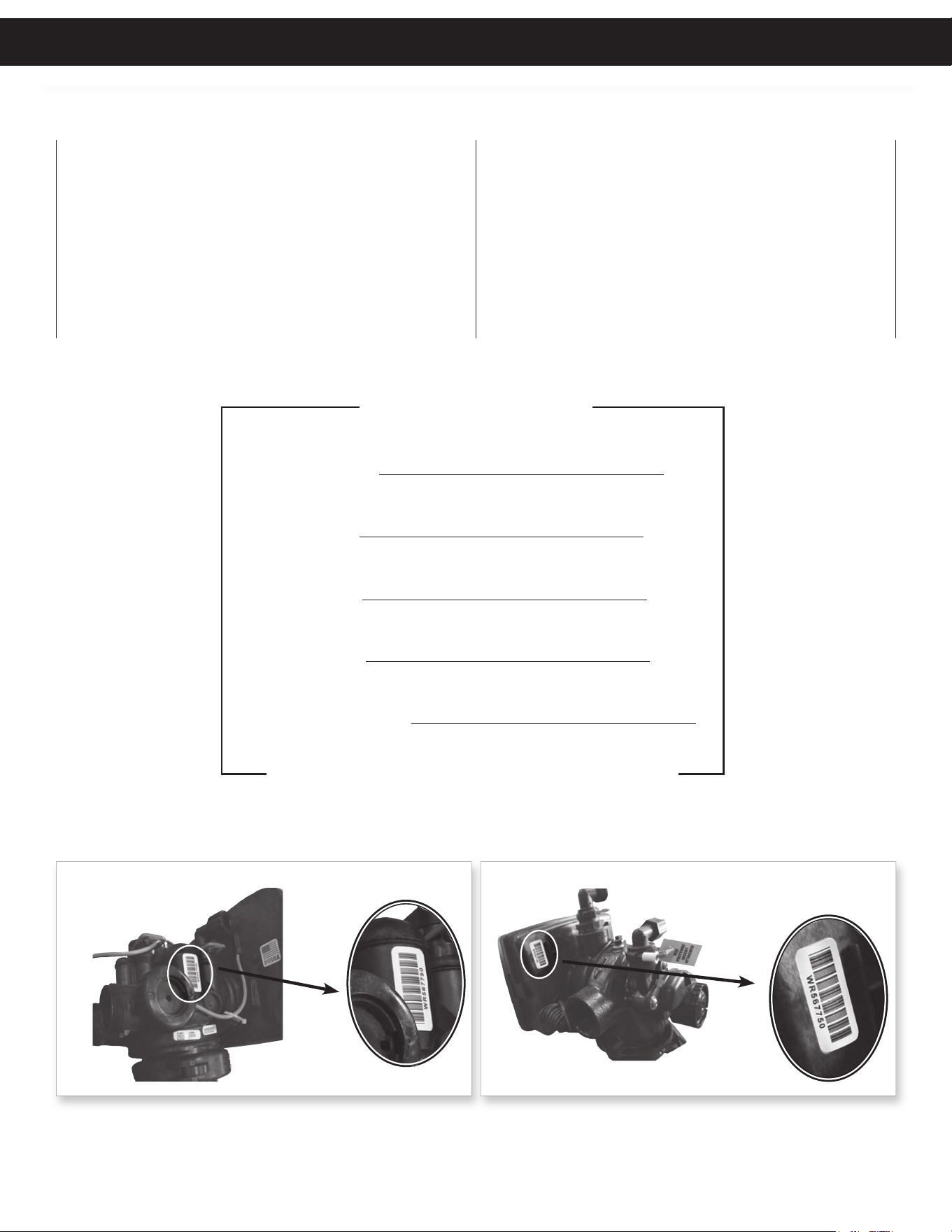
*Serial Number Loca ons
1” to 1.25” Units 1.5” to 2” Units
PRE-INSTALLATION INSTRUCTIONS
Table of Contents Pre-Installation
4
MANUAL REGENERATION
If you need to initiate a manual
regeneration, either immediately, or the
same night at the preprogrammed time
for regeneration (typically 2:00 AM),
complete the following steps.
For Immediate Regeneration:
Press and hold ����� until valve motor
starts (typically 3 seconds).
For Regeneration the same night:
Press and release ����� (notice that
flashing “REGEN TODAY” appears).
ERROR
If the display toggles between “Error”
and an error code (i.e. a number), call a
service technician and report the error
code.
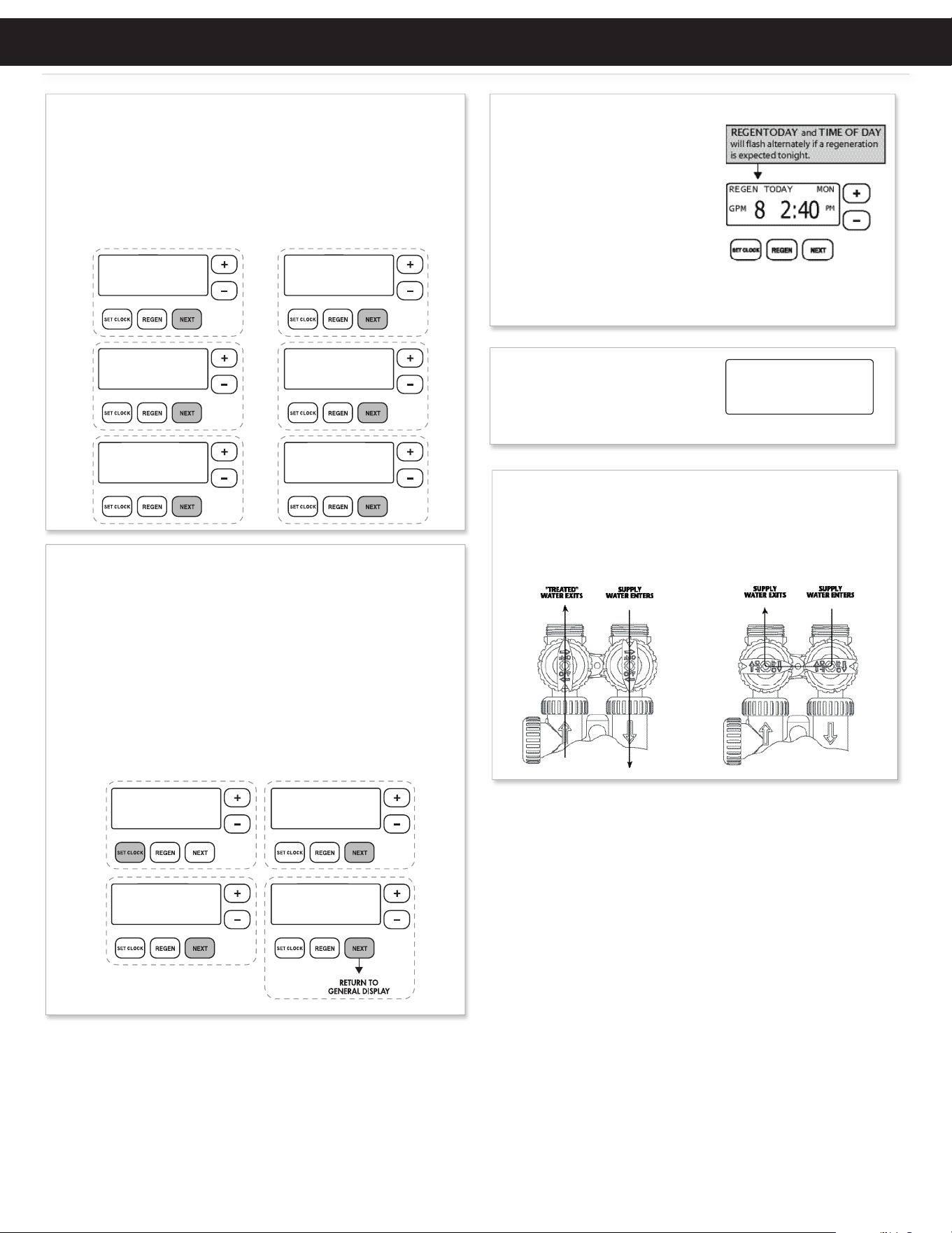
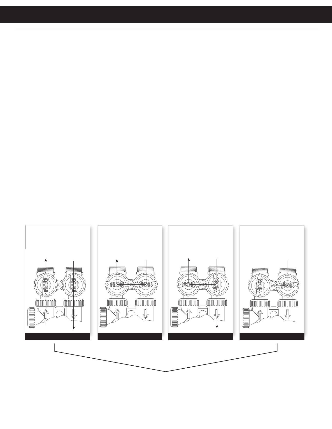
BYPASS VALVE OPERATION (1” & 1.25” ONLY)
To shut off water to the system, position arrow handles as shown in
the bypass operation diagram below. If your valve doesn’t look like the
diagram below, contact your service technician for instructions on how to
shut off water.
NORMAL OPERATION BYPASS OPERATION
ERROR
106
CALL FOR SERVICE
GENERAL OPERATION
When the system is operating, one
of six displays will be shown:
Pressing ���� will toggle between
the six choices.
1. Time of day/gpm
2. Flow rate
3. Vacation mode
4. Capacity remaining
5. Days to a regen
6. Dealer name and phone number
TO SET TIME OF DAY
In the event of a prolonged power outage, time of day flashes, indicating
that this needs to be reset. All other information will be stored in memory
no matter how long the power outage.
1. Accessed by pressing ��� �����
2. Adjust hours with + and — buttons, AM/PM toggles at 12
3. Press ����
4. Adjust minutes with + and — buttons
5. Press ����
6. Adjust current day with + and — buttons
7. Press ���� to complete and return to normal operation
ON VACATION
NO
DAYS TO A REGEN
GPM
1
8
CAPACITY REMAINING
GPM GAL
300
8
FLOW RATE
GPM
8.0
TIME OF DAY MON
GPM
2:408
PM
PHONE NUMBER
DEALER NA
CURRENT DAY
SET
MON
TIME MINUTES
SET
TIME HOUR
SET
2:00
AM
6:35
PM
QUICK REFERENCE GUIDE
Quick Reference Guide
5
DEFAULT PROGRAMMING SETTINGS
For initial set-up or to make adjustments, please refer to Initial Controller Set-Up Section.
Accessed by pressing and holding the ���� and + buttons simultaneously.
Press the ���� button to advance to the next screen.
ALARM BUZZER START
SET
6:00
AM
ALARM BUZZER END
SET
8:00
PM
SERVICE ALARM
SET
OFF
REGEN TIME MINUTES
SET
2:00
AM
REGEN TIME HOUR
SET
2:00
AM
DAYS BETWEEN REGEN
SET
10
WATER HARDNESS
SET
20
GR
LIGHT NORMALLY
SET
ON
SERVICE ALARM
SET
OFF
GAL
YR
TIME OF DAYMON
PM
GPM
2:408
QUICK REFERENCE GUIDE
1” – 1.25”SINGLE 1.5” – 2.0 ”SINGLE
1.5” – 2.0 ” TWIN1” – 1.25 ” TWIN ALT
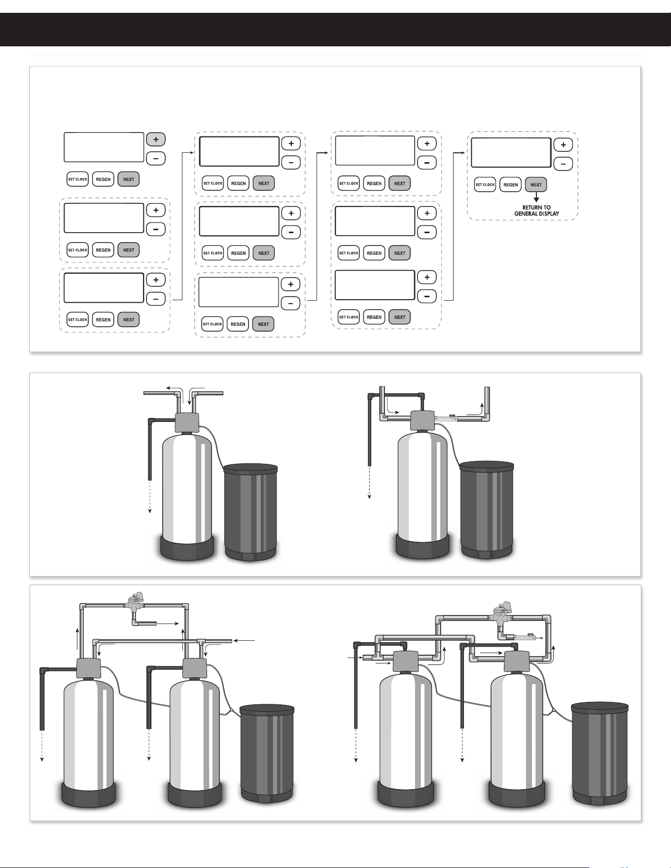
TYPICAL INSTALLATION CONFIGURATIONS
Quick Reference Guide
6
“TREATED”
WATER EXITS
SUPPLY
WATER ENTERS
NORMAL
OPERATION
POSITION
BYPASS POSITION
DIAGNOSTIC
POSITION
SHUT OFF
POSITION
FIGURE 1
SUPPLY
WATER EXITS
SUPPLY
WATER ENTERS
FIGURE 3
SUPPLY
WATER EXITS
SUPPLY
WATER ENTERS
FIGURE 2
NO
WATER EXITS
SUPPLY WATER IS
SHUT OFF
TO THE HOUSE
AND THE VALV E
FIGURE 4
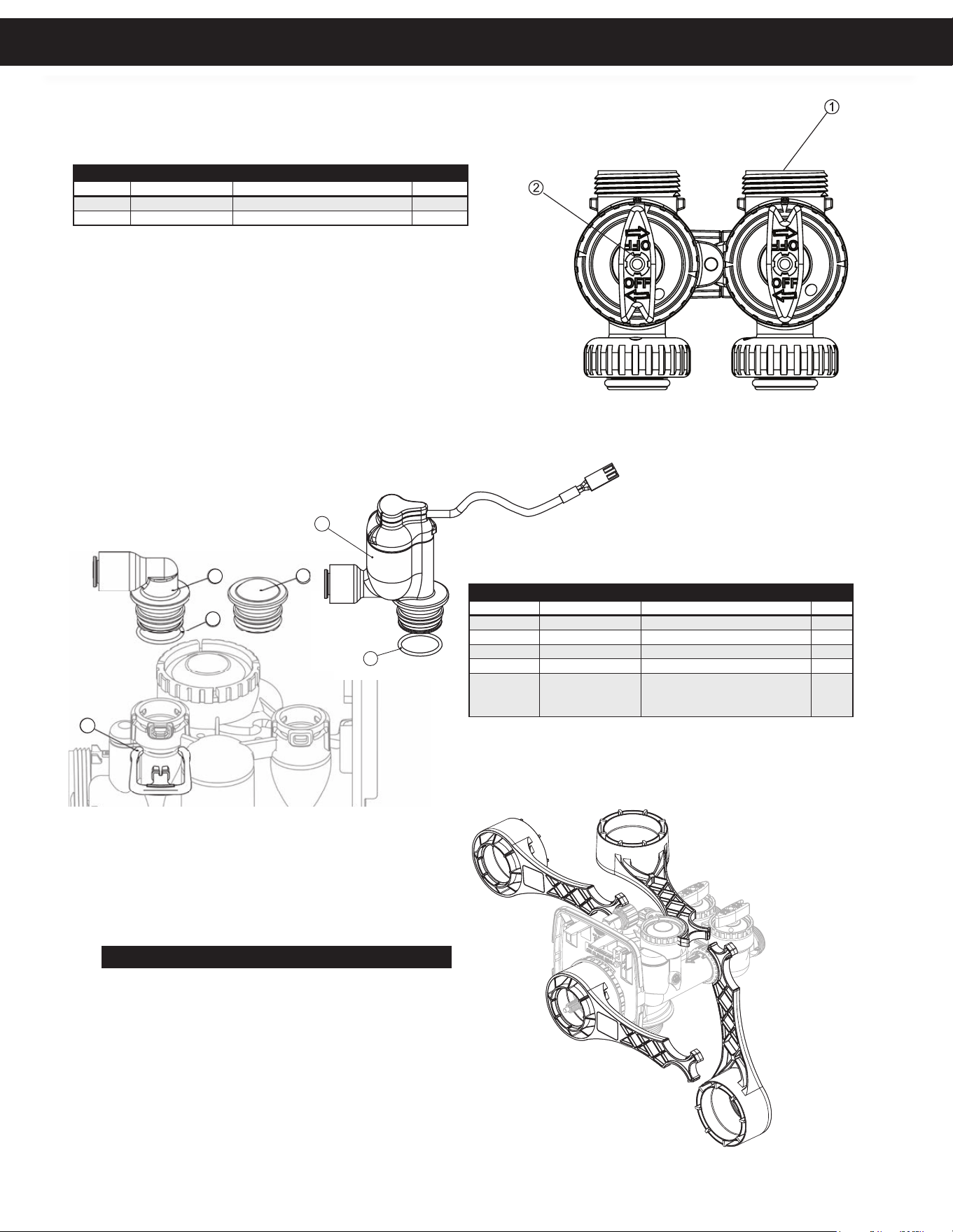
The bypass valve is typically used to isolate the control valve from the plumbing system’s water pressure in order to perform control
valve repairs or maintenance. The 1” full flow bypass valve incorporates four positions, including a diagnostic position that allows a
service technician to have pressure to test a system while providing untreated bypass water to the building. Be sure to install bypass
valve onto main control valve, before beginning plumbing. Or, make provisions in the plumbing system for a bypass. The bypass body
and rotors are glass-filled Noryl® and the nuts and caps are glass-filled polypropylene. All seals are self-lubricating EPDM to help prevent
valve seizing after long periods of non-use. Internal “O” Rings can easily be replaced if service is required.
The bypass consists of two interchangeable plug valves that are operated independently by red arrow shaped handles. The handles
identify the direction of flow. The plug valves enable the bypass valve to operate in four positions.
1. NORMAL OPERATION POSITION: The inlet and outlet handles point in the direction of flow indicated by the engraved
arrows on the control valve. Water flows through the control valve for normal operation of a water softener or filter. During the
regeneration cycle this position provides regeneration water to the unit, while also providing untreated water to the distribution
system (Fig. 1).
2. BYPASS POSITION: The inlet and outlet handles point to the center of the bypass. The system is isolated from the water
pressure in the plumbing system. Untreated water is supplied to the building (Fig. 2).
3. DIAGNOSTIC POSITION: The inlet handle points toward the control valve and the outlet handle points to the center of bypass
valve. Untreated supply water is allowed to flow to the system and to the building, while not allowing water to exit from the system
to the building (Fig. 3). This allows the service technician to test the unit and perform other functions without disrupting the water
going to the building.
NOTE: The system must be rinsed before returning the bypass valve to the normal position.
4. SHUT OFF POSITION: The inlet handle points to the center of the bypass valve and the outlet handle points away from the
control valve. The water is shut off to the building. The water treatment system will depressurize upon opening a tap in the building.
A negative pressure in the building combined with the unit being in regeneration could cause a siphoning to the building. If water
is available on the outlet side of the unit, it is an indication of water bypassing the system (Fig. 4) (i.e. a plumbing cross-connection
somewhere in the building).
1” – 1.25” BYPASS VALVE
Integrated Bypass valve available on 1” – 1.25” units only.
1 “ – 1.25” Bypass Valve
7
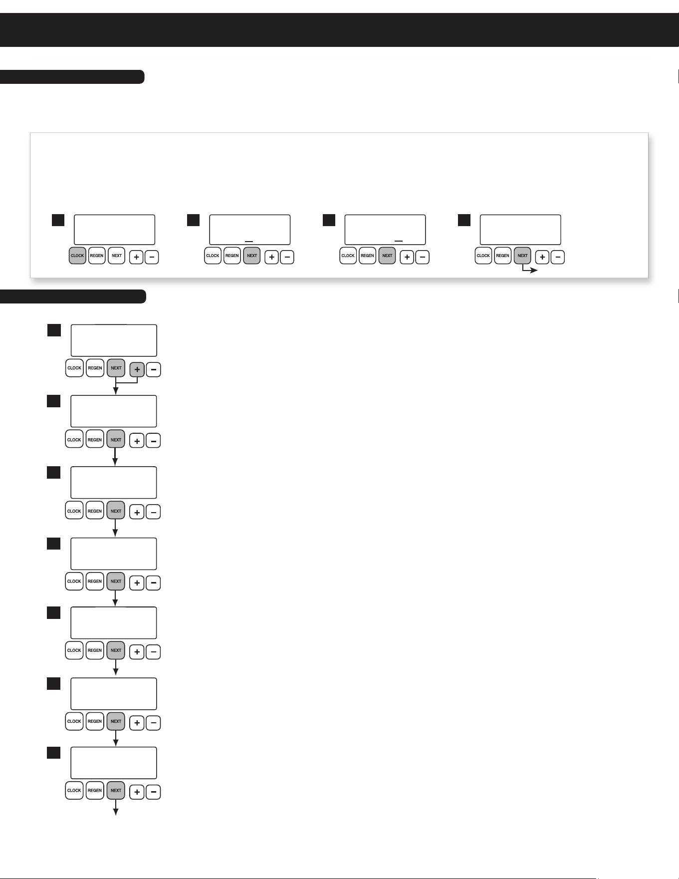
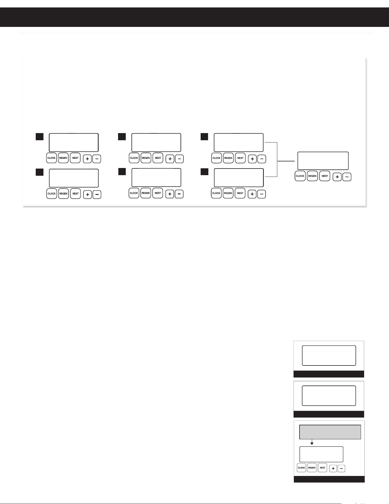
Typically, time of day should only need to be set after extended power outages or when daylight saving time begins or ends or after the
battery has been replaced. If an extended power outage occurs, the time of day will flash on and off indicating that the time should be reset.
To set the clock:
STEP 1 – Press the CLOCK button.
STEP 2 – Set the hour of the day using
+ or – buttons. AM/PM toggles after 12. Press NEXT to go to step 3.
STEP 3 – Set the minutes using
+ or – buttons. Press NEXT to go to step 4 or REGEN to return to previous step.
STEP 4 – Set the day of the week using
+ or – buttons. Press NEXT to exit clock setting or REGEN to return to previous step.
1
TIME HOUR
AM
SET
2:00
TIME MINUTES
AM
SET
2:00
2 3
CURRENT DAY
SET
MON
4
return to general display
TIME OF DAY MON
PM
GPM
2:408
1. Set Time of Day
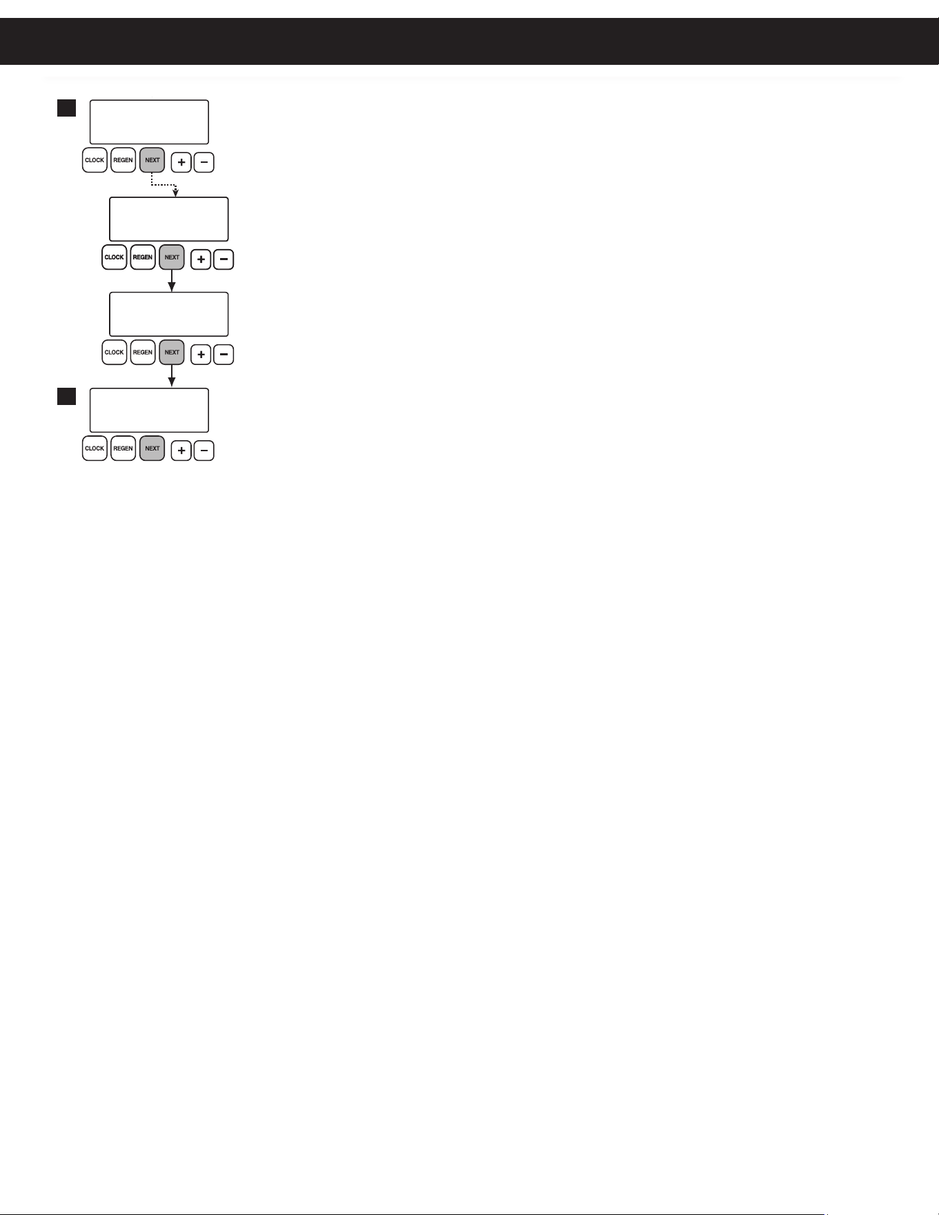
INITIAL CONTROLLER SET-UP
The manufacturer has preset the unit so that the gallons between regenerations will be automatically calculated
after the hardness is entered. Press NEXT to cycle to the next step or REGEN to return to the previous step.
STEP 1 – Press and hold the NEXT and
+ buttons simultaneously for 3 seconds.
STEP 2 – HARDNESS: Use the
+ or – buttons to adjust the hardness value in grains per gallons. Adjustable
from 1 to 150 gpg in 1 grain increments (default setting is 20).
The hardness value is based on the actual compensated hardness of the water and must be set by
an authorized dealer following an on-site water analysis. Adjusting the number will only impact the
frequency of regeneration and will not alter or affect the hardness of the water treated by the unit.
Note: If a resin media is used, increase the grains per gallon if soluble iron is present
(1 ppm = 4 gpg). This screen will not display if “FILTER” mode is selected.
STEP 3 – DAYS BETWEEN REGENERATION (DAY OVERRIDE): Use the
+ or – buttons to adjust the day
override. Adjustable from 1-28 days or OFF. The manufacturer has factory set 10 days as the default.
The Day Override value represents the maximum number of days between regenerations. If any number
is set (1-28 days), a regeneration will be scheduled for that day if the gallon capacity has not been met. If
OFF is set, the unit will only initiate a regeneration once the gallon capacity has been met.
STEP 4 – REGENERATION HOUR: Use the
+ or – buttons to adjust the time of day the unit will regenerate.
AM/PM toggles after 12. The manufacturer has factory set 2:00 A.M. as the default setting which is
recommended for a normal household.
STEP 5 – REGENERATION MINUTES: Use the + or – buttons to set minutes.
STEP 6 –
SERVICE ALARM GALLONS: Use the + or – buttons to schedule a service alarm by gallons. Adjustable in
100 gallon increments or OFF. The manufacturer has factory set OFF as the default.
This feature is typically set by the installing dealer to warn the homeowner that service is required after
a number of gallons have been consumed. If the feature is active, a specific gallon amount will appear.
For more information regarding how to set service alarms, the installer should consult the master
programming guide that corresponds to the unit being installed.
Press the NEXT button three times to advance to the next screen.
STEP 7 – SERVICE ALARM TIME: Use the + or – buttons to schedule a service alarm in years. Adjustable in .25
year increments or OFF. The manufacturer has factory set OFF as the default.
This feature is typically set by the installing dealer to warn the homeowner that service is required after
an amount of time has passed. If the feature is active, a specific number of days will appear. For more
information regarding how to set service alarms, the installer should consult the master programming
guide that corresponds to the unit being installed.
Press the NEXT button three times to advance to the next screen.
2. Programming
1
DAYS BETWEEN REGEN
SET
10
3
WATER HARDNESS
SET
20
2
REGEN TIME HOUR
AM
GR
SET
2:00
4
REGEN TIME MINUTES
AM
SET
2:00
5
SERVICE ALARM
GAL
SET
OFF
6
SERVICE ALARM
YR
SET
OFF
7
ALARM BUZZER
SET
ON
8
LIGHT NORMALLY
SET
ON
9
ALARM BUZZER
SET
6:00
ALARM BUZZER START
SET
ALARM BUZZER END
SET
10:00
AM
PM
TIME OF DAY MON
PM
GPM
2:408
con nued on next page
Initial Controller Set-Up
8
INITIAL CONTROLLER SET-UP
STEP 8 – ALARM BUZZER: Use the + or – buttons to turn the alarm ON or OFF. Unit is set to ON by default.
Alarm will sound after a regeneration warning the owner of possible valve errors or other issues. This
alarm is a short 0.5 second burst every 3 seconds. When alarm buzzer is set to ON, pressing the NEXT
button proceeds to the Alarm Start Time screen. This feature allows the installer to choose a time when
the owner will be home or awake to hear the alarm.
BUZZER START TIME: Press the + or – buttons to select the hour when the buzzer should begin sounding.
AM/PM toggles after 12. Default setting is 6:00 a.m.
BUZZER STOP TIME: Press the
+ or – buttons to select the hour when the buzzer should stop sounding.
AM/PM toggles after 12. Default setting is 10:00 p.m.
STEP 9 – BACKLIGHT DISPLAY CONTROL: Use the + or – buttons to turn the backlight setting ON or OFF. If
unit is set to OFF, the backlight will turn off after 5 minutes of inactivity.
Press NEXT to return to General Display.
1
DAYS BETWEEN REGEN
SET
10
3
WATER HARDNESS
SET
20
2
REGEN TIME HOUR
AM
GR
SET
2:00
4
REGEN TIME MINUTES
AM
SET
2:00
5
SERVICE ALARM
GAL
SET
OFF
6
SERVICE ALARM
YR
SET
OFF
7
ALARM BUZZER
SET
ON
8
LIGHT NORMALLY
SET
ON
9
ALARM BUZZER
SET
6:00
ALARM BUZZER START
SET
ALARM BUZZER END
SET
10:00
AM
PM
TIME OF DAY MON
PM
GPM
2:408
Initial Controller Set-Up
9
1. GENERAL OPERATING DISPLAYS: When the system is operating, one of six displays may be shown and will alternate with the installing
dealer’s name and phone number for future service. Pressing NEXT will alternate between the displays.
1. Time of Day Screen: Displays the current time of day, the day of the week, and flow rate.
2. Flow Rate Screen: Displays the current treated water flow rate through the system in Gallons Per Minute.
3. Vacation Mode Screen: This setting is not used in commercial applications.
4. Capacity Remaining Screen: Displays the amount of gallons of treated water remaining until the system triggers a regeneration.
5. Days to a Regen Screen: Displays the number of days until the system triggers a regeneration. Based on the days override value.
6. Dealer Name Screen: Displays dealer specific name and phone number. This scrolling display will only appear if set by the dealer.
*In multi-valve installations, inactive units will display “StandBy” in the top-left corner of the screen.
OPERATING DISPLAYS AND MAINTENANCE
1
FLOW RATE
GPM
8.0
ON VACATION
2
6
TIME OF DAY MON
PM
GPM
2:408 NO
GPM
38
3
DAYS TO A REGEN
5
555 5555555
DEALER NA
CAPACITY REMAINING
GAL
GPM
16008
4
If the system has called for a regeneration that will occur at the preset time of regeneration, the words “REGEN TODAY” will appear on the display.
If a water meter is installed, “GPM” flashes on the display when water is being treated, indicating gallons per minute flowing through the system.
2. GENERAL NAVIGATION
During normal operation, the default user displays are “time of day” and “gallons per minute”. Flow rate, vacation mode, capacity remaining, and
days to a regeneration are optional displays. For more explanation, consult the “operating displays and maintenance section”. Pressing the NEXT
button on a general operating screen will cycle through the available operating displays.
In any screen other than a general operating display, the NEXT button will proceed to the next step, the REGEN button will return to a previous
step, and the CLOCK button will return to the general operating displays. Any changes made prior to the exit will be incorporated. If no buttons
are pressed within five minutes, the display will return to the general operating displays.
4. REGENERATION AND STANDBY DISPLAY: Typically, a system is set to regenerate at a time of no water usage. If there is a demand
for water when the system is regenerating, untreated water will be delivered. When the system begins to regenerate, the display will include
information about the step of the regeneration process and the time remaining for that step to be completed. The system runs through the steps
automatically and will reset itself to provide treated water when the regeneration has been completed.
In multi-valve installations, a unit will display “standby” in the top-left corner of the screen when it is inactive. The screen will return to a general
operating display or a regeneration display once the unit is called back into service.
3. DOUBLE REGENERATION
Two generations within 24 hours are possible with a return to the preset program. To initiate a double
regeneration:
1. Press the REGEN button once. “REGEN TODAY” will flash on the display.
2. Press and hold the REGEN button for three seconds until a regeneration begins.
Once the valve has completed the immediate regeneration, the valve will regenerate once more during the
preset time.
5. MANUAL REGENERATION: Sometimes there may be a need to regenerate a unit before the control
valve calls for it. This may be needed if a period of heavy water use is anticipated or when the system has
been operating without salt.
• To initiate a manual regeneration at the next preset regeneration time, press and release the
REGEN button. The words “REGEN TODAY” will flash on the display to indicate that the system will
regenerate at the scheduled regeneration time (see the Programming Procedures section). If you
pressed the REGEN button in error, pressing the button again will cancel the command.
• To initiate a manual regeneration immediately, press and hold the REGEN button for three seconds.
The system will begin to regenerate immediately. This command cannot be canceled.
REGEN DISPLAY
BACKWASH
8:22
STANDBY DISPLAY
STANDBY
MANUAL REGEN
REGEN TODAY MON
GPM
2:408
PM
REGEN TODAY and TIME OF DAY
will ash alternately if a regeneration
is expected tonight.
STANDBY
Operating Displays & Maintenance
10
OPERATING DISPLAYS AND MAINTENANCE
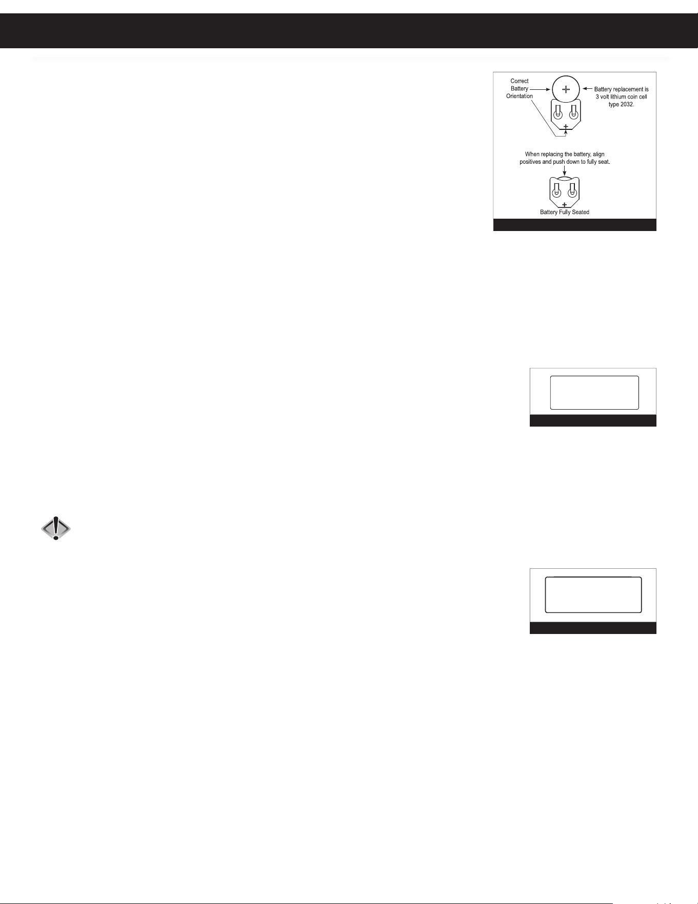
6. POWER LOSS AND BATTERY REPLACEMENT: If an extended power outage occurs, the
control valve will retain the time of day settings until the board’s battery is depleted. Once the battery is
depleted, the display will appear dark and absent of any information. If this occurs, following these steps
will determine if the problem is a low battery or a board failure.
To determine if the battery is depleted:
1. Remove valve cover. Disconnect power from PC Board at the four pin connector at the bottom
of the board.
2. Remove battery. Reference the Parts Breakdown section of this manual for location.
3. Wait five minutes for board to de-energize.
4. With the battery out, re-connect the power supply to the board. The board’s display should
begin to show information.
This indicates that the board is operating correctly. If the display does not work, call
installing dealer for service.
5. To replace with new battery, unplug transformer from outlet. Install a 3 volt Lithium Coin Cell type 2032 battery, available at most stores.
Plug unit back into outlet.
It is important to replace the battery with the valve unplugged to avoid causing a short and potentially ruining the board.
6. Reset the time of day (see programming procedures) and initiate regeneration (see operating displays and maintenance).
If these procedures do not remedy the problem, please consult the installing dealer for service.
7. ERROR MESSAGE: If the word “ERROR” appears and flashes alternately with the dealer name and phone
number, record the ERROR number and contact your servicing dealer promptly. This indicates that the control
valve was not able to function properly.
8. BRINE TANK MAINTENANCE AND SALT: Refill the brine tank as necessary, making sure at least 1/3 of
the brine tank is full at all times. Without proper salt levels, the water softener may not operate properly.
Because “typical” settings of this water softener include a dry salt storage feature (no water in brine tank between regeneration), the
manufacturer recommends the use of solar salt for best results. The brine tank is manufactured for the use of solar, pellets or rock salt. Do not use
block salt. If pellet or rock salt is used, a cleaning of the brine tank every six months is recommended. If the dry salt storage feature is not being
utilized, block salt may be used.
Caution: With some models the manufacturer does NOT recommend the use of any resin cleaners, nor placing any resin cleaners into
the brine tank. Furthermore, do not use any salt that indicates it is an iron cleaning salt or that contains any cleaning additives.
This may be harmful to the water softener and for human consumption. Consult dealer for proper cleaning instructions.
9. CHECK SALT INDICATOR AND AUDIBLE ALARM: This control valve is equipped with a low salt
warning to alert homeowners that the system is operating in a low salt condition. This usually indicated that
the salt level in the brine tank is too low to operate properly. If “CHECK SALT” appears on the screen, there will
usually be an audible alarm that sounds also (if turned on), alerting you to these conditions.
TO TURN OFF ALARM: If the audible alarm sounds due to a low salt condition, press any button on the
face of the control valve to turn off. If the salt is not added to the brine tank before
the next regeneration, the CHECK SALT indicator will alarm again.
BATTERY REPLACEMENT
ERROR SCREEN
ERROR
106
CALL FOR SERVICE
SALT ALARM SCREEN
CHECK
SALT
Operating Displays & Maintenance
11
ERROR CAUSE
1. No display on PC board
A. Depleted battery
B. Control valve power adapter not plugged into outlet or power cord end not
connected to PC board connection
C. Improper power supply
D. Defective power adapter
E. Defective PC board
F. No power at electric outlet
2. PC board does not display correct time of day
A. Power adapter plugged into electric outlet controlled by light switch
B. Tripped breaker switch and/or tripped GFI
C. Power outage
D. Defective PC board
3. Display does not indicate that water is flowing. Refer
to user instructions for how the display indicates
water is flowing.
A. Bypass valve in bypass position
B. Meter is not connected to meter connection on PC board
C. Restricted/stalled meter turbine
D. Meter wire not installed securely into three pin connector
E. Defective meter
F. Defective PC board
4. Control valve regenerates at wrong time of day
A. Power outage
B. Time of day not set correctly
C. Time of regeneration set incorrectly
D. Control valve set at “on 0” (immediate regeneration)
E. Control valve set at “NORMAL + on 0” (delayed and/or immediate)
5. Time of day flashes on and off A. Power outage
6. Control valve does not regenerate automatically when
the correct button(s) is depressed and held.
For timeclock valves the buttons are & .
For all other valves the button is REGEN.
A. Broken drive gear or drive cap assembly
B. Broken piston rod
C. Defective PC board
D. Cover installed incorrectly
7. Control valve does not regenerate automatically but
does when the correct button(s) is depressed and held.
For timeclock valves the buttons are & .
For all other valves the button is REGEN.
A. Bypass valve in bypass position
B. Meter is not connected to meter connection on PC board
C. Restricted/stalled meter turbine
D. Incorrect programming
E. Meter wire not installed securely into three pin connector
F. Defective meter
G. Defective PC board
8. Hard or untreated water is being delivered
A. Bypass valve is open or faulty
B. Media is exhausted due to high water usage
C. Meter not registering
D. Water quality fluctuation
E. No regenerant or low level of regenerant in regenerant tank
F. Control fails to draw in regenerant
G. Insufficient regenerant level in regenerant tank
H. Damaged seal/stack assembly
I. Control valve body type and piston type mix matched
J. Fouled media bed
9. Control valve uses too much regenerant
A. Improper refill setting
B. Improper program settings
C. Control valve regenerates frequently
VALVE AND PC BOARD ERRORS
Troubleshooting Guide
12
ERROR CAUSE
10. Residual regenerant being delivered to service
A. Low water pressure
B. Incorrect, damaged, or restricted injector
C. Restricted drain line
11. Excessive water in regenerant tank
A. Improper program settings
B. Plugged injector
C. Drive cap assembly not tightened in properly
D. Damaged seal/stack assembly
E. Restricted or kinked drain line
F. Plugged backwash flow controller
G. Missing refill flow controller
12. Control valve fails to draw in regenerant
A. Injector is plugged
B. Faulty regenerant piston
C. Regenerant line connection leak
D. Drain line restriction or debris cause excess back pressure
E. Drain line too long or too high
F. Low water pressure
13. Water running to drain
A. Power outage during regeneration
B. Damaged seal/stack assembly
C. Piston assembly failure
D. Drive cap assembly not tightened in properly
14. E1, Err – 1001, Err – 101 =
Control unable to sense motor movement
A. Motor not inserted full to engage pinion, motor wires broken or disconnected
B. PC board not properly snapped into drive bracket
C. Missing reduction gears
15. E2, Err – 1002, Err – 102 = Control valve motor ran
too short and was unable to find the next cycle
position and stalled
A. Foreign material is lodged in control valve
B. Mechanical binding
C. Main drive cap too tight
D. Improper voltage being delivered to PC board
16. E3, Err – 1003, Err – 103 = Control valve motor ran too
long and was unable to find the next cycle position
A. Motor failure during a regeneration
B. Foreign matter built up on piston and stack assemblies creating friction and drag
enough to time out motor
C. Drive bracket not snapped in properly and out enough that reduction gears and
drive gear do not interface
17. E4, Err – 1004, Err – 104 = Control valve motor ran too
long and timed out trying to reach home position
A. Drive bracket not snapped in properly and out enough that reduction gears and drive
gear do not interface
18. Err – 1006, Err – 106, Err – 116 = MAV/ SEPS/ NHBP/
AUX MAV valve motor ran too long and unable to
find the proper park position
Motorized Alternating Valve = MAV
Separate Source = SEPS
No Hard Water Bypass = NHBP
Auxiliary MAV = AUX MAV
A. Control valve programmed for ALT A or B, nHbP, SEPS, or AUX MAV without
having a MAV or NHBP valve attached to operate that function
B. MAV/NHBP motor wire not connected to PC board
C. MAV/NHBP motor not fully engaged with reduction gears
D. Foreign matter built up on piston and stack assemblies creating friction and drag
enough to time out motor
19. Err – 1007, Err – 107, Err – 117 = MAV/ SEPS/NHBP/
AUX MAV valve motor ran too short (stalled) while
looking for proper park position
Motorized Alternating Valve = MAV
Separate Source = SEPS
No Hard Water Bypass = NHBP
.Auxiliary MAV = AUX MAV
A. Foreign material is lodged in MAV/NHBP valve
B. Mechanical binding
VALVE AND PC BOARD ERRORS
Troubleshooting Guide

13
VALVE AND PC BOARD ERRORS
ERROR CAUSE
20. Err – 109 A. Invalid motor state detected
21. Err – 201 A. Invalid regeneration cycle step detected
22. Err – 204 = Leak detected
A. Occurs when dP input is active for “ALARM” and the input is closed. The alarm buzzer
will activate and the screen will display the error.
23. Err – 400
*
Memory Errors
*(All 400 errors pertain to
memory related errors)
A. Depleted Battery
B. Defective PC Board
Troubleshooting Guide
14
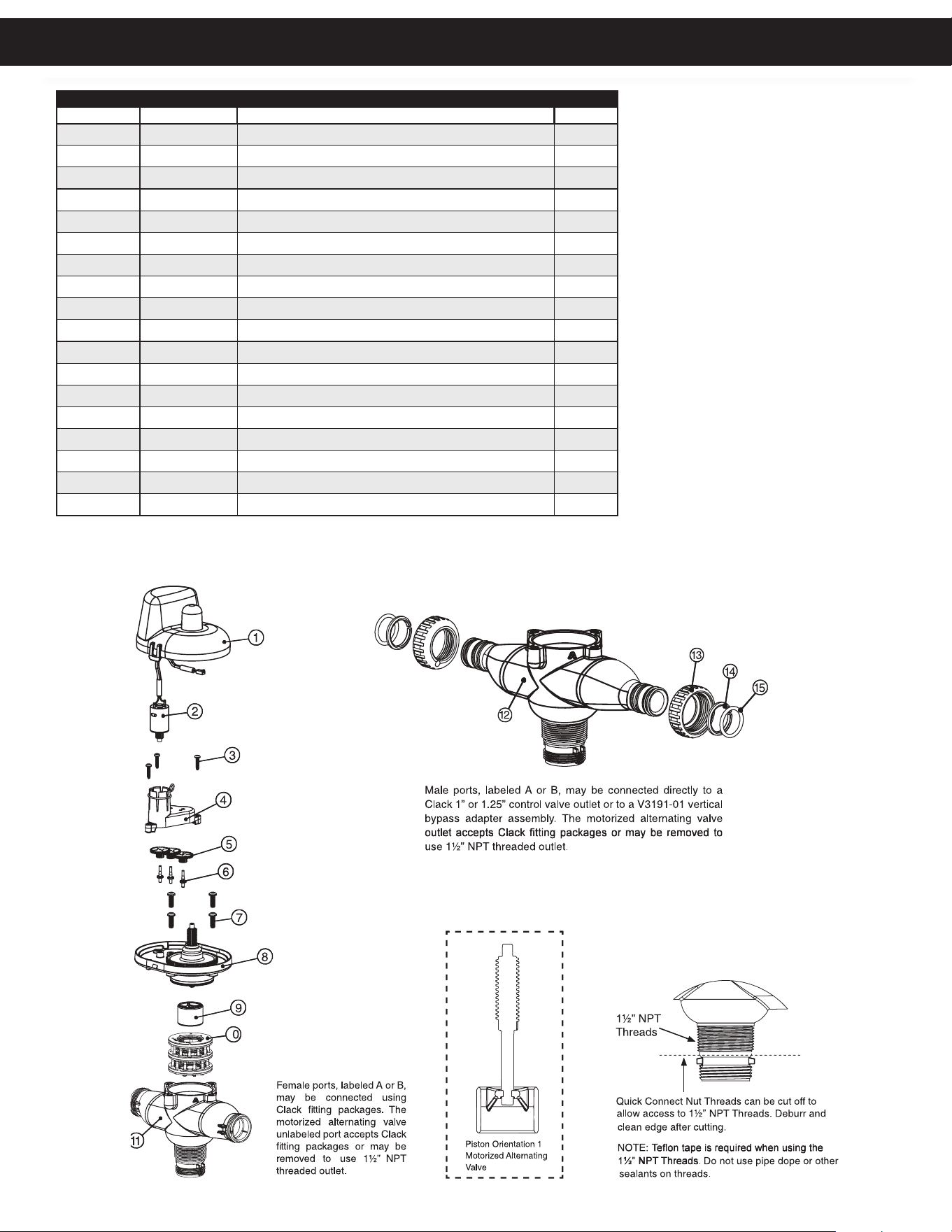
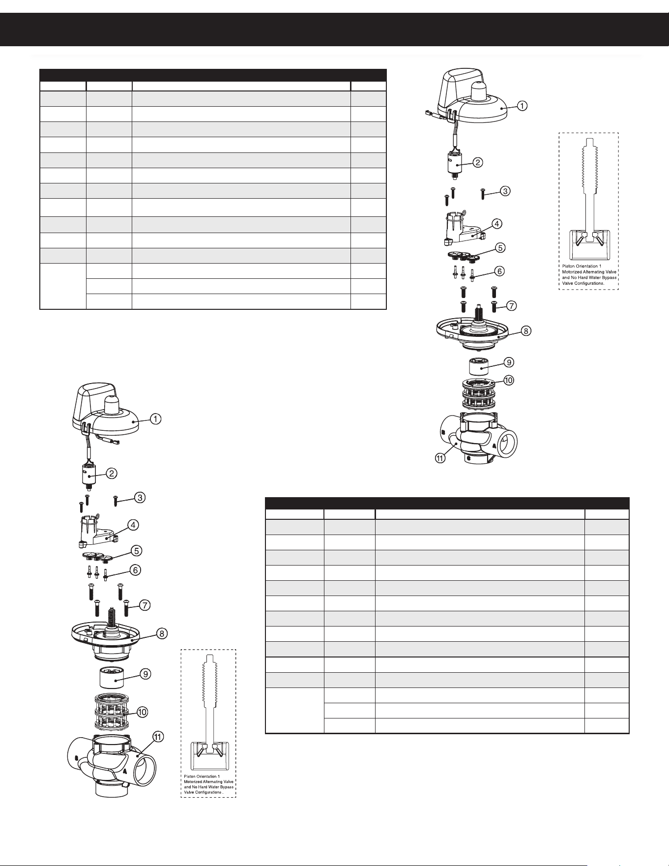
FRONT COVER AND DRIVE ASSEMBLY
Item # Part # Description Qty.
1 CV3540-NOLAB Black cover 1
2 CV3107-01 Motor Assembly 1
3 CV32002-A Drive assembly (includes #5 and #6) -
4
CV3502WE PC board (used on chlorine generator models) 1
CV4022WU PC board (standard) 1
5 CV3110 Drive gear, 12 x 36 3
6 CV3109 Drive gear cover 1
not
shown
CV3526 Transformer, 110V-15V, DC (used on chlorine generator models) 1
CV3186 Transformer, 110V-12V, AC (standard) 1
CV3543 Optional weather cover 1
CV4276-15 System controller power cord, 15 foot 1
CV4276-36 System controller power cord, 36 foot 1
REPLACEMENT PARTS
NOTE: Battery Location
2
1
3
5
4
6
Replacement Parts
15
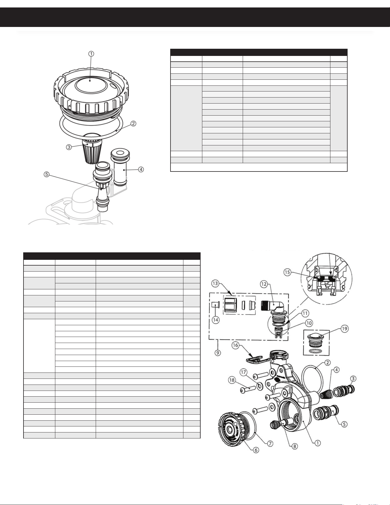
PISTON ASSEMBLY
Item #. Part # Description Qty.
1
CV3005-02 1” spacer stack assembly 1
CV3430-01 1.25” and 1.5” spacer stack assembly 1
2 CV3004 Drive cap assembly 1
3 CV3135 O-ring 228 (drive cap o-ring) 1
4
CV3011 1” piston assembly downflow 1
CV3011-01 1” piston assembly upflow 1
CV3407 1.25” and 1.5” downflow piston assembly 1
5 CV3174 Regenerant piston 1
6 CV3180 O-ring 337 1
7 CV3105 O-ring 215 1
8 CV3556 Screw, 1/4-20x1-1/2 18-8SS 1
9 CCI-00318337 Nut, 1/4-20 HEX 18-8SS 1
10 CV3016 QC2 clamp assembly (includes screw & nut) 1
11 CV3452 O-ring 230 (tank flange o-ring) 1
12 CV3015 Quick Connect Tank Adaptor 1
13
CV3001-04 1” body assembly downflow 1
CV3020 1.25” body assembly downflow 1
14 CV3541 Drive backplate 1
REPLACEMENT PARTS
QC Adapter on 1” Versions
Only
Replacement Parts
16
REPLACEMENT PARTS
CONTROL VALVES
9
2
4
3
6
5
8
1
7
10
1.5” VALVE BODY ASSEMBLY
Item # Part # Description Qty.
1 CV3004 Drive Cap Assembly 1
2 CV3135 O-ring 228 (drive cap o-ring) 1
3 CV3407 1.25” and 1.5” downflow piston assembly 1
4 CV3174 Regenerant Piston 1
5 CV3423 1.5 Backplate Dowel 1
6 CV3430-01 1.25” and 1.5” spacer stack assembly 1
7 CV3541 Drive Backplate 1
8 CV3419 O-Ring 347 1
9 CV3641 O-Ring 328 1
10 CV3950-01 1.5 Valve Body Downflow 1
Replacement Parts
17
REPLACEMENT PARTS
2” VALVE BODY ASSEMBLY
Item # Part # Description Qty.
1 CV3726 WS2 Brine Piston Assembly 1
2 CV3725 WS2 Piston Downflow Assembly 1
3 CV3452 O-ring 230 (tank flange o-ring) 1
4 CV3728 WS2 Drive Cap Assembly 1
5 CV3724 Washer, Flat SS 1/4 1
6 CV3642 Bolt, BHCS S/S 1/4-20 X 1.25 1
7 CV3541 Drive Backplate 1
8 CV3729 WS2 Stack Assembly 1
9 CV3419 O-Ring 347 for WS15 1
10 CV3641 O-Ring 225 (for bodies with NPT threads) 1
11 CV3700-01 WS2 Body, NPT 1
not
shown
CV3468 WS2H Plug, 1/4 Hex NPT 1
CD1300-01 Top Baffle DFSR Clack 1.5/50mm 1
CONTROL VALVES
9
2
4
3
6
5
8
1
7
10
Replacement Parts
18
3
4
2
1
5
2
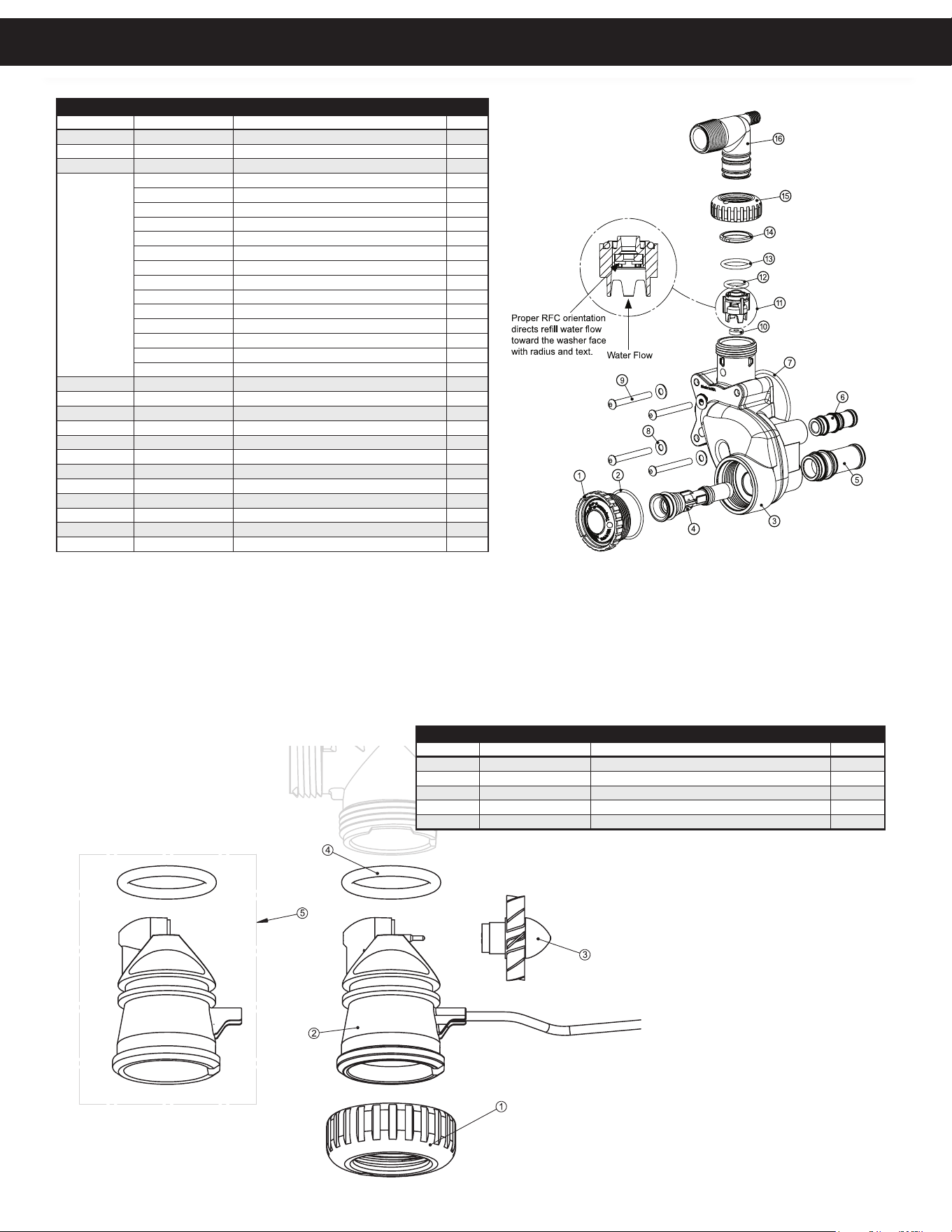
REFILL PORT ASSEMBLY
Item # Part # Description Qty.
1 CV4144 3/8” Elbow, Parker fitting 1
2 CV3163 O-ring 019 1
3 CV3195-01 Refill port plug assembly 1
4 CV4615 Elbow locking clip 1
5 CV3395
Chlorine Generator (Black)
*Only available on 1" and 1.25"
valves on 16" or smaller tanks
1
BYPASS VALVE
Item # Part # Description Qty.
1 CV3006 Bypass assembly 1
2 CV3147 Bypass handles 2
Loosens Injector And
Bypass Caps
Loosens Drive Cap
Although no tools are necessary to assemble or
disassemble the valve, the Service Wrench, (shown
in various positions on the valve) is available to aid
in assembly or disassembly.
SERVICE WRENCH - CV3193-02
REPLACEMENT PARTS
Replacement Parts
19
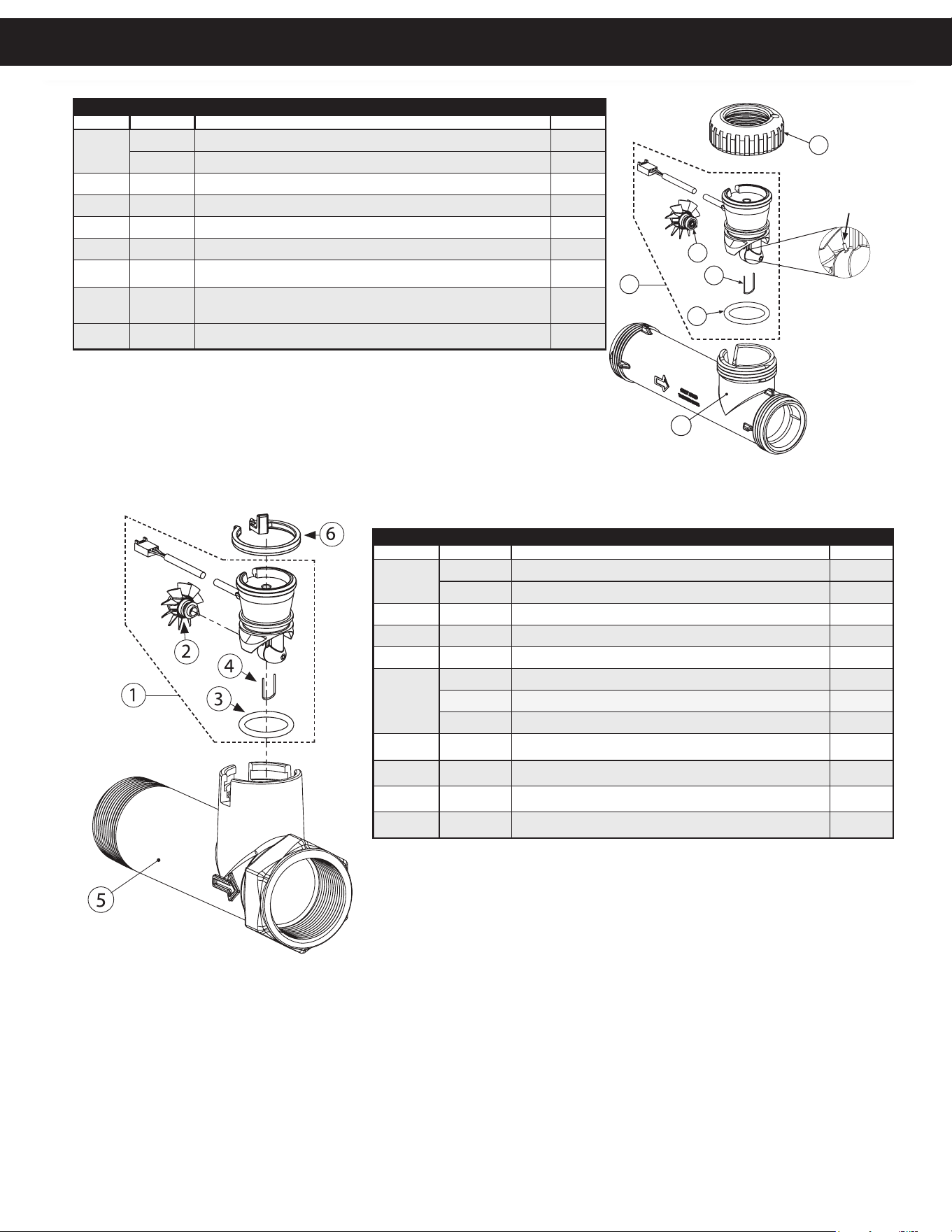
1" INJECTOR ASSEMBLIES
Item # Part # Description Qty.
1 CV3176 Injector cap 1
2 CV3152 O-ring 135 1
3 CV3177-01 Injector screen 1
4 CV3010-1Z Injector assembly plug 1
5
CV3010-1A A injector assembly, black
1
CV3010-1B B injector assembly, brown
CV3010-1C C injector assembly, violet
CV3010-1D D injector assembly, red
CV3010-1E E injector assembly, white
CV3010-1F F injector assembly, blue
CV3010-1G G injector assembly, yellow
CV3010-1H H injector assembly, green
CV3010-1I I injector assembly, orange
CV3010-1J J injector assembly, light blue
CV3010-1K K injector assembly, light green
not shown CV3170 O-ring 011, lower *
not shown CV3171 O-ring 013, upper *
*The injector plug and the injector each use one lower and one upper o-ring
1.5" INJECTOR ASSEMBLIES
Item # Part # Description Qty.
1 CV3967 WS1.5 Injector Body, Welded Assembly 1
2 CV3441 O-Ring 226 1
3
CV3968 WS1.5 Injector Feed Tube Dnflw, BLK 1
CV3968-01 WS1.5 Injector Feed Tube Upflw, Gray 1
4 CV3177-01 WS1 Injector Screen 1
5
CV3969 WS1.5 Injector Draw Tube Dnflw, Black
1
CV3969-01 WS1.5 Injector Draw Tube Upflw, Gray
6 CV3176 WS1 Injector Cap 1
7 CV3152 O-Ring 135 1
8
CV3010-15B WS1.5 Injector Assembly B 1
CV3010-15C WS1.5 Injector Assembly C 1
CV3010-15D WS1.5 Injector Assembly D 1
CV3010-15E WS1.5 Injector Assembly E 1
CV3010-15F WS1.5 Injector Assembly F 1
CV3010-15G WS1.5 Injector Assembly G 1
CV3010-15H WS1.5 Injector Assembly H 1
CV3010-15I WS1.5 Injector Assembly I 1
CV3010-15Z WS1.5 Injector Plug 1
9 CV3498 Refill Flow Control 1/2" 1
10 CV3428 WS 1.5 Refill Retainer Assembly (.5 GPM) 1
11 CV3163 O-Ring 019 1
12 CH4612 Regenerant Elbow with Flow Control 1
13 CJCPG-8PBLK Nut, Compression 1/2" Black 1
14 CJCP-P-8 Insert, Polytube 1/2" 1
15 CV3182 Refill Flow Control (0.5 GPM) 1
16 CH4615 Retaining Clip 1
17 CV3724 Washer, Flat Stainless Steel 1
18 CV3642 Bolt, BHCS Stainless Steel 1
19 CV3195-01 Refill Port Plug 1
REPLACEMENT PARTS
Replacement Parts
20
WATER METER AND METER PLUG
Item # Part # Description Qty.
1 CV3151 Nut, 1” QC 1
2 CV3003 Meter assembly, includes items 3 & 4 1
3 CV3118-01 Turbine assembly 1
4 CV3105 O-ring 215 1
5 CV3003-01 Meter plug assembly 1
2" INJECTOR ASSEMBLIES
Item # Part # Description Qty.
1 CV3477 WS2H Injector Cap 1
2 CV3152 O-Ring 135 1
3 CV3727 WS2 Injector Body Assembly 1
4
CV3010-2R-15B WS2/2H INJ R Assembly W/CV3010-15B 1
CV3010-2S-15C WS2/2H INJ S Assembly W/CV3010-15C 1
CV3010-2T-15D WS2/2H INJ T Assembly W/CV3010-15D 1
CV3010-2U-15E WS2/2H INJ U Assembly W/CV3010-15E 1
CV3010-2V-15F WS2/2H INJ V Assembly W/CV3010-15F 1
CV3010-2W-15G WS2/2H INJ W Assembly W/CV3010-15G 1
CV3010-2X-15H WS2/2H INJ X Assembly W/CV3010-15H 1
CV3010-2A WS2/2H Injector Assembly A 1
CV3010-2B WS2/2H Injector Assembly B 1
CV3010-2C WS2/2H Injector Assembly C 1
CV3010-2D WS2/2H Injector Assembly D 1
CV3010-2E WS2/2H Injector Assembly E 1
CV3010-2F WS2/2H Injector Assembly F 1
CV3010-2G WS2/2H Injector Assembly G 1
5 CV3731 WS2 Injector Draw Tube, Dwn Assembly 1
6 CV3730 WS2 Injector Feed Tube, Dwn Assembly 1
7 CV3315 O-Ring 231 1
8 CV3724 Washer Flat SS 1/4 1
9 CV3643 Bolt BHCS S/S 1/4-20 x 2.25 1
10 CV3162-022 WS1 DLFC022-3/4 1
11 CV3231 WS2H Refill Flow Control Retainer 1
12 CV3277 O-Ring 211 1
13 CV3105 O-Ring 215 1
14 CV3150 WS1 Split Ring 1
15 CV3151 WS1 Nut 1 QC 1
16 CV3149 WS1 FTG 1 PVC Male NPT Elbow 1
REPLACEMENT PARTS
Replacement Parts
21
Water
Flow
5
8
Drain
Line
1”
4
6
7
Proper DLFC orientation
directs water flow towards
the washer face with
rounded edge.
3
1
2
2
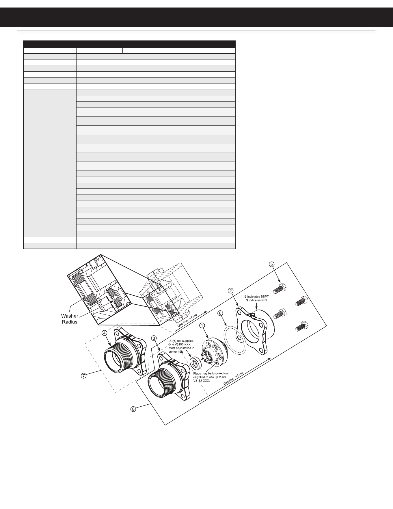
DRAIN LINE ASSEMBLY 1”
Item # Part # Description Qty.
1 CH4615 Elbow locking clip 1
2
CV3166 Drain FTG body 1
1
CV3166-01 FTG flow control body 1
3 CV3167 Drain FTG adapter 1 1
4 CV3163 O-ring 019 1
5 CV3150 Split ring 1
6 CV3151 Nut 1" QC 1
7 CV3105 O-ring 215
8
CV3190-090 9.0 gpm DLFC for 1” elbow
One DLFC
must be
used if 1"
fitting is
used
CV3190-100 10.0 gpm DLFC for 1” elbow
CV3190-110 11.0 gpm DLFC for 1” elbow
CV3190-130 13.0 gpm DLFC for 1” elbow
CV3190-150 15.0 gpm DLFC for 1” elbow
CV3190-170 17.0 gpm DLFC for 1” elbow
CV3190-200 20.0 gpm DLFC for 1” elbow
CV3190-250 25.0 gpm DLFC for 1” elbow
9
CV3008-04 FTG Drain 1" Strt No/Sil
1
Water flow
Proper DLFC orientation
directs water flow towards
the washer face with
rounded edge.
2
3
8
5
7
6
1
4
DRAIN LINE ASSEMBLY 3/4”
Item # Part # Description Qty.
1 CH4615 Elbow locking clip 1
2 CPKP10TS8-BULK Optional insert, 5/8” tube 1
3 CV3192 Optional nut, 3/4” drain elbow 1
4 CV3158-02 Drain elbow, 3/4” NPT with O-ring 1
5 CV3163 O-ring 019 1
6 CV3159-01 DLFC retainer assembly 1
7
CV3162-007 0.7 DLFC for 3/4” elbow
1
CV3162-010 1.0 DLFC for 3/4” elbow
CV3162-013 1.3 DLFC for 3/4” elbow
CV3162-017 1.7 DLFC for 3/4” elbow
CV3162-022 2.2 DLFC for 3/4” elbow
CV3162-027 2.7 DLFC for 3/4” elbow
CV3162-032 3.2 DLFC for 3/4” elbow
CV3162-042 4.2 DLFC for 3/4” elbow
CV3162-053 5.3 DLFC for 3/4” elbow
CV3162-065 6.5 DLFC for3/4” elbow
CV3162-075 7.5 DLFC for 3/4” elbow
8 CV3331 Drain elbow and retainer assembly
Items 2 and 3, nut and insert are only used with 1/2” I.D. by 5/8” O.D.
polytubing. For other piping material, the 3/4” NPT is used.
REPLACEMENT PARTS
Replacement Parts
22
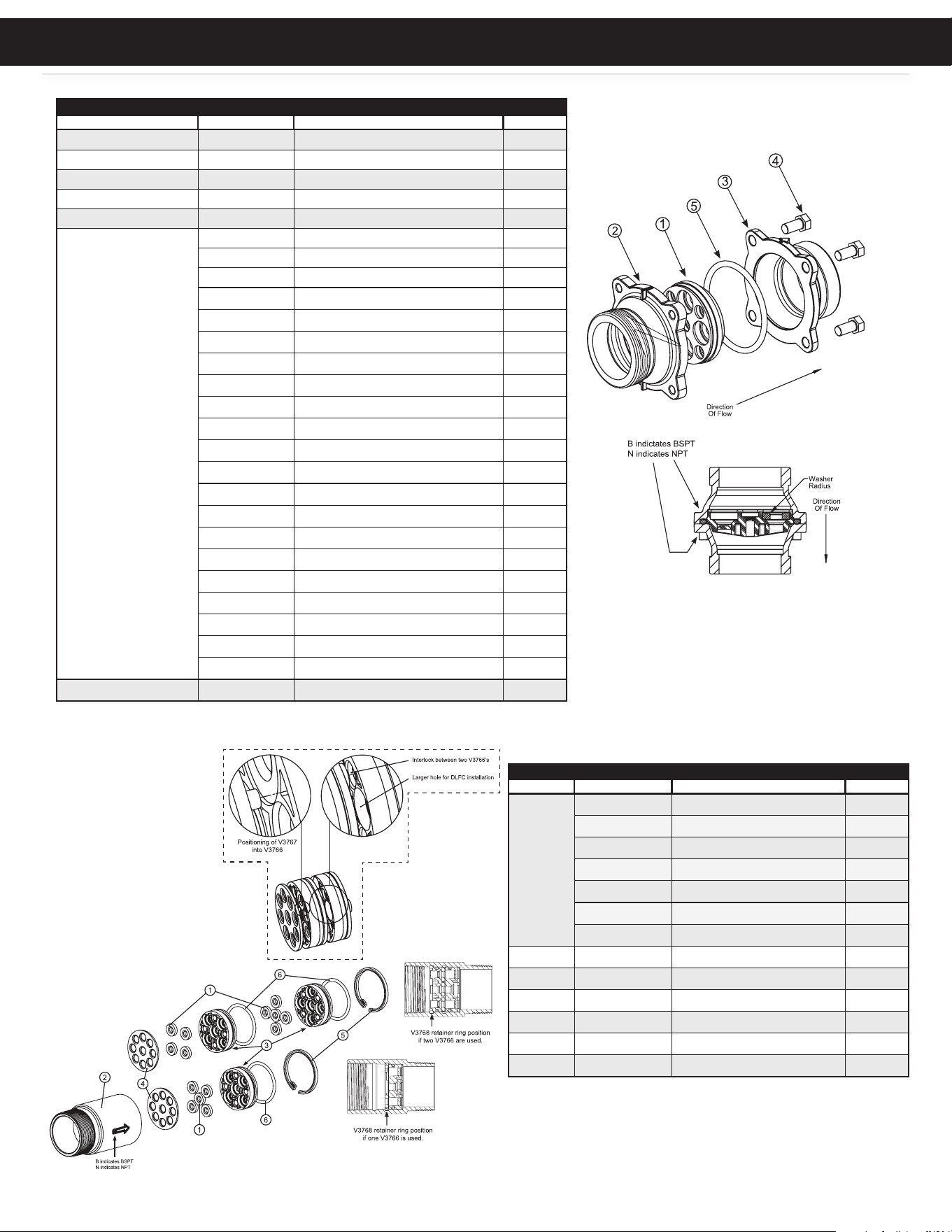
DRAIN LINE ASSEMBLY 1.25” AND 1.5”
Item # Part # Description Qty.
1 CV3081 WS15 RETAINER DLFC ASSEMBLY 1
2 CV3645 WS15 DLFC FLANGE OUTLET FNPT 1
3 CV3646 WS15 DLFC FLANGE INLET MNPT 1
4 CV3647 WS125 DLFC FLANGE INLET MNPT 1
5 CV3652 BOLT, HEX HD, 5/16 - 18 x 3/4 1
6 CV3441 O-RING, 226 1
NOT SHOWN
(install one CV3190-XXX in
center hole; knock out plugs
allow installation of up to 6
more of CV3162-XXX)
CV3162-007 WS1 DLFC 0.7 GPM FOR 3/4 1
CV3162-010 WS1 DLFC 1.0 GPM FOR 3/4 1
CV3162-013 WS1 DLFC 1.3 GPM FOR 3/4 1
CV3162-017 WS1 DLFC 1.7 GPM FOR 3/4 1
CV3162-022 WS1 DLFC 2.2 GPM FOR 3/4 1
CV3162-027 WS1 DLFC 2.7 GPM FOR 3/4 1
CV3162-032 WS1 DLFC 3.2 GPM FOR 3/4 1
CV3162-042 WS1 DLFC 4.2 GPM FOR 3/4 1
CV3162-053 WS1 DLFC 5.3 GPM FOR 3/4 1
CV3162-065 WS1 DLFC 6.5 GPM FOR 3/4 1
CV3162-075 WS1 DLFC 7.5 GPM FOR 3/4 1
CV3162-090 WS1 DLFC 9.0 GPM FOR 3/4
1
CV3162-100 WS1 DLFC 10.0 GPM FOR 3/4
1
CV3190-090 WS1 DLFC 9.0 GPM FOR 1
1
CV3190-100 WS1 DLFC 10.0 GPM FOR 1
1
CV3190-110 WS1 DLFC 11.0 GPM FOR 1
1
CV3190-130 WS1 DLFC 13.0 GPM FOR 1
1
CV3190-150 WS1 DLFC 15.0 GPM FOR 1
1
CV3190-170 WS1 DLFC 17.0 GPM FOR 1
1
CV3190-200 WS1 DLFC 20.0 GPM FOR 1
1
CV3190-250 WS1 DLFC 25.0 GPM FOR 1
1
7 CV3079 WS DLFC 1.25 x 1.5 ASSEMBLY
1
8 CV3080 WS DLFC 1.5 x 1.5 ASSEMBLY
1
REPLACEMENT PARTS
h
1.25 and 1.5 Drain Line
Assembly
Replacement Parts
23
REPLACEMENT PARTS
DRAIN LINE ASSEMBLY 2”
Item # Part # Description Qty.
1 CV3052 WS15 RETAINER DLFC ASSEMBLY 1
2 CV3245 WS15 DLFC FLANGE OUTLET FNPT 1
3 CV3246 WS15 DLFC FLANGE INLET MNPT 1
4 CV3273 WS125 DLFC FLANGE INLET MNPT 1
5 CV3441 O-RING, 338 1
NOT SHOWN
(Install one or more DLFC
washer. Up to 5 of the CV3162-
XXX may be installed in the
small holes. Up to 4 of the
CV3190-XXX may be installed
in the large holes. )
CV3162-007 WS1 DLFC 0.7 GPM FOR 3/4 1
CV3162-010 WS1 DLFC 1.0 GPM FOR 3/4 1
CV3162-013 WS1 DLFC 1.3 GPM FOR 3/4 1
CV3162-017 WS1 DLFC 1.7 GPM FOR 3/4 1
CV3162-022 WS1 DLFC 2.2 GPM FOR 3/4 1
CV3162-027 WS1 DLFC 2.7 GPM FOR 3/4 1
CV3162-032 WS1 DLFC 3.2 GPM FOR 3/4 1
CV3162-042 WS1 DLFC 4.2 GPM FOR 3/4 1
CV3162-053 WS1 DLFC 5.3 GPM FOR 3/4 1
CV3162-065 WS1 DLFC 6.5 GPM FOR 3/4 1
CV3162-075 WS1 DLFC 7.5 GPM FOR 3/4 1
CV3162-090 WS1 DLFC 9.0 GPM FOR 3/4 1
CV3162-100 WS1 DLFC 10.0 GPM FOR 3/4 1
CV3190-090 WS1 DLFC 9.0 GPM FOR 1 1
CV3190-100 WS1 DLFC 10.0 GPM FOR 1 1
CV3190-110 WS1 DLFC 11.0 GPM FOR 1 1
CV3190-130 WS1 DLFC 13.0 GPM FOR 1 1
CV3190-150 WS1 DLFC 15.0 GPM FOR 1 1
CV3190-170 WS1 DLFC 17.0 GPM FOR 1 1
CV3190-200 WS1 DLFC 20.0 GPM FOR 1 1
CV3190-250 WS1 DLFC 25.0 GPM FOR 1 1
CV3051 WS2 DLFC NPT ASSEMBLY
DRAIN LINE ASSEMBLY 3”
Item # Part # Description Qty.
1
CV3190-090 WS1 DLFC 9.0 GPM FOR 1
1
CV3190-100 WS1 DLFC 10.0 GPM FOR 1 1
CV3190-110 WS1 DLFC 11.0 GPM FOR 1 1
CV3190-130 WS1 DLFC 13.0 GPM FOR 1 1
CV3190-150 WS1 DLFC 15.0 GPM FOR 1 1
CV3190-170 WS1 DLFC 17.0 GPM FOR 1 1
CV3190-200 WS1 DLFC 20.0 GPM FOR 1 1
2 CV3765-01 WS3 DLFC HOUSING NPT 1
3 CV3766 WS3 DLFC RETAINER 1
4 CV3767 WS3 DLFC RETAINER COVER 1
5 CV3768 WS3 DLFC RETAINER RING 1
6 CV3769 O-RING, 336 1
CV3764 WS3 DLFC NPT ASSEMBLY
Drain Line Assembly
2” and 3”
Drain Line Assembly
2” and 3”
Replacement Parts
24
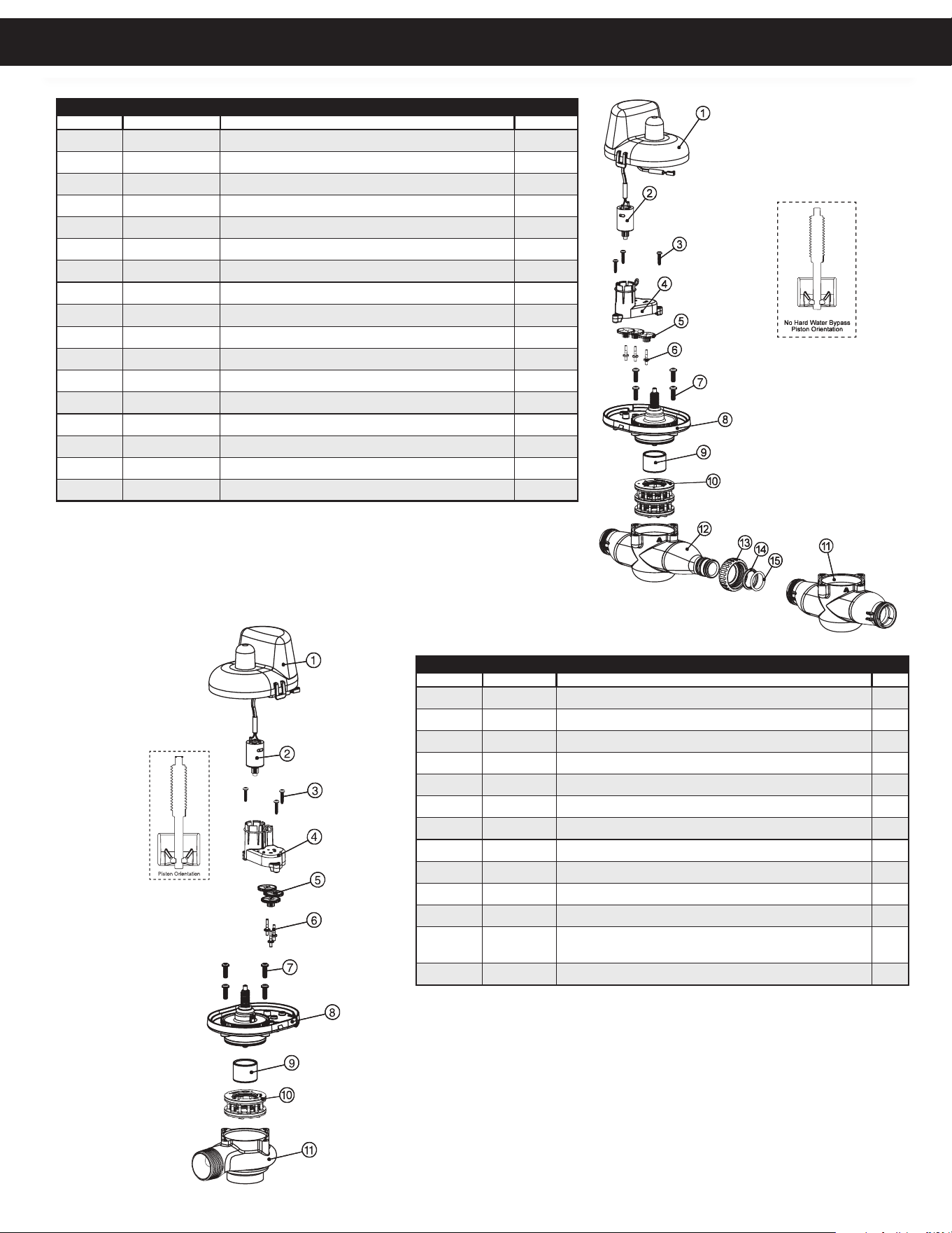
REPLACEMENT PARTS
1” AND 1.25” NHWBP ASSEMBLIES
Item # Part # Description Qty.
1
CV3073 MAV/NOWHBY COVER ASSEMBLY
1
2 CV3476 WS MOTOR ASSEMBLY, 8 FT 1
3 CV3592 SCREW, #8-3/4, PHPN T-25 SS 1
4 CV3262-01 WS1.5 & 2 ALT/2BY REDUCTION GEAR COVER ASSEMBLY 1
5 CV3110 WS1 DRIVE REDUCING GEAR 12 x 36 1
6 CV3264 WS2 BYPASS REDUCTION GEAR AXLE 1
7 CV3527 SCREW, 1/4-20 x 3/4, BHSCS SS 1
8 CV3072 MAV/NOWHBY 1/1.25/1.5 DRIVE ASSEMBLY 1
9
CV3506-01 MAV/NOHRD 1/1.25/1.5 PISTON
1
10 CV3074 MAV/NOHWBY 1/1.25/1.5 STACK ASSEMBLY 1
11 CV3521FF NOHRD WATER BYPASS BODY ASSEMBLY F-F 1
12 CV3521FM NOHRD WATER BYPASS BODY ASSEMBLY F-M 1
13 CV3151 WS1 NUT, QC 1
14 CV3150 WS1 SPLIT RING 1
15 CV3105 O-RING, 215 1
CV3070FF NO HARD WATER BYPASS 1/1.25 F-F ASSEMBLY
CV3070FM NO HARD WATER BYPASS 1/1.25 F-M ASSEMBLY
1.5” NHWBP ASSEMBLIES
Item # Part # Description Qty.
1
CV3073 MAV/NOWHBY COVER ASSEMBLY
1
2 CV3476 WS MOTOR ASSEMBLY, 8 FT 1
3 CV3592 SCREW, #8-3/4, PHPN T-25 SS 1
4 CV3262-01 WS1.5 & 2 ALT/2BY REDUCTION GEAR COVER ASSEMBLY 1
5 CV3110 WS1 DRIVE REDUCING GEAR 12 x 36 1
6 CV3264 WS2 BYPASS REDUCTION GEAR AXLE 1
7 CV3527 SCREW, 1/4-20 x 3/4, BHSCS SS 1
8 CV3072 MAV/NOWHBY 1/1.25/1.5 DRIVE ASSEMBLY 1
9 CV3506-01 MAV/NOHRD 1/1.25/1.5 PISTON 1
10 CV3886 WS15 NHWBY STACK ASSEMBLY 1
11 CV3832-01 WS15 NHWBY BODY M x F NPT 1
NOT
SHOWN
CV3805 STRAIN RELIEF COVER KIT
1
CV3097 NO HARD WATER BYPASS 1.5 M x F NPT ASSEMBLY
Replacement Parts
25
REPLACEMENT PARTS
2” NHWBP ASSEMBLIES
Item # Part # Description Qty.
1
CV3073 MAV/NOWHBY COVER ASSEMBLY
1
2 CV3476 WS MOTOR ASSEMBLY, 8 FT 1
3 CV3592 SCREW, #8-3/4, PHPN T-25 SS 1
4 CV3262-01 WS1.5 & 2 ALT/2BY REDUCTION GEAR COVER ASSEMBLY 1
5 CV3110 WS1 DRIVE REDUCING GEAR 12 x 36 1
6 CV3264 WS2 BYPASS REDUCTION GEAR AXLE 1
7 CV3642 SCREW, 1/4-20 x 1-1/4, BHSCS SS 1
8 CV3078 MAV/NOHWBY 2 DRIVE ASSEMBLY 1
9 CV3634-01 MAV/NOHWBY 2 PISTON 1
10 CV3887 WS2 NHWBY STACK ASSEMBLY 1
11 CV3828-01 WS2 NHWBY BODY M x F, NPT 1
NOT
SHOWN
CV3805 STRAIN RELIEF COVER KIT
1
CV3098 MOTOR ALT VALVE 2 NPT REV2 ASSEMBLY
Replacement Parts
26
REPLACEMENT PARTS
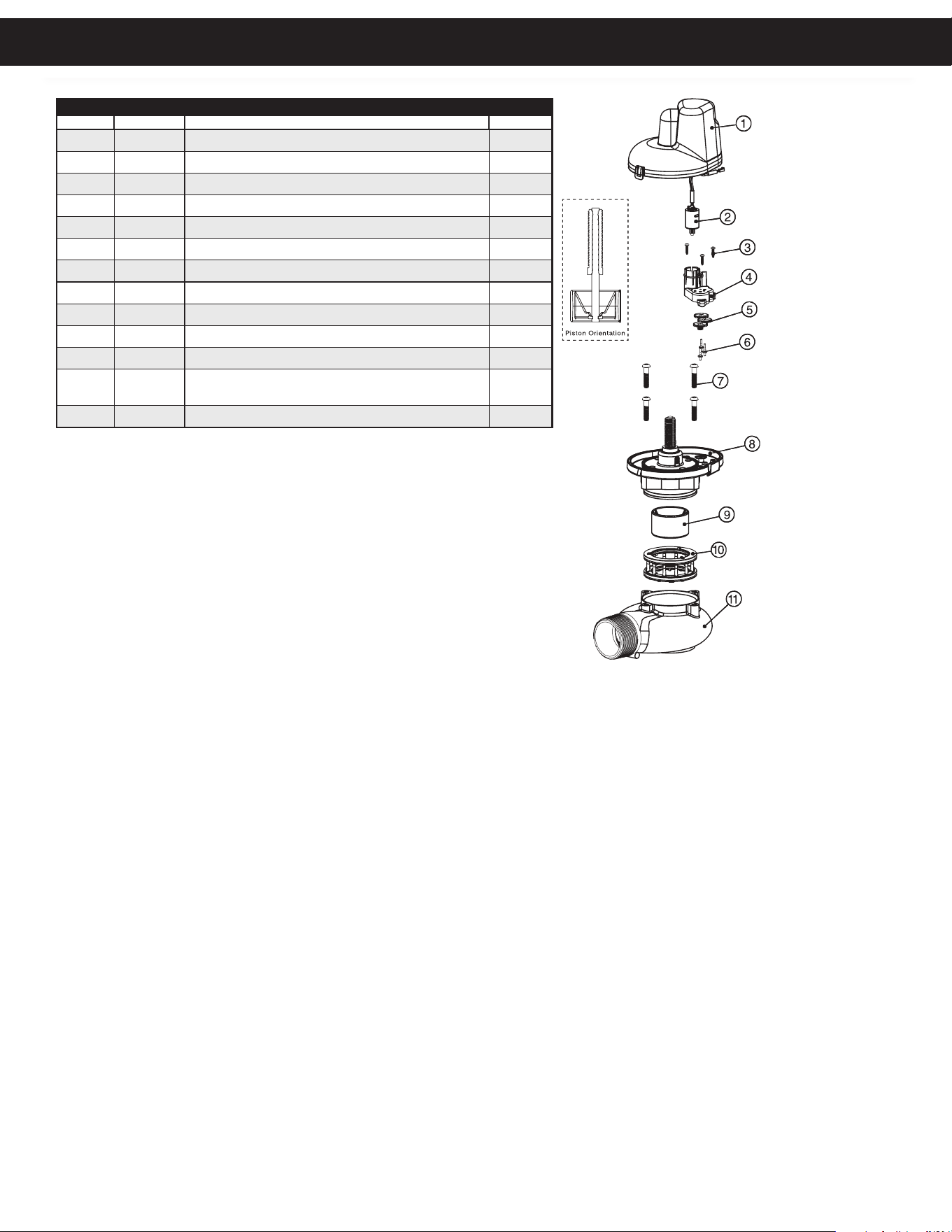
1” AND 1.25” MAV ASSEMBLIES
Item # Part # Description Qty.
1
CV3073 MAV/NOWHBY COVER ASSEMBLY
1
2 CV3476 WS MOTOR ASSEMBLY, 8 FT 1
3 CV3592 SCREW, #8-3/4, PHPN T-25 SS 1
4 CV3262-01 WS1.5 & 2 ALT/2BY REDUCTION GEAR COVER ASSEMBLY 1
5 CV3110 WS1 DRIVE REDUCING GEAR 12 x 36 1
6 CV3264 WS2 BYPASS REDUCTION GEAR AXLE 1
7 CV3527 SCREW, 1/4-20 x 3/4, BHSCS SS 1
8 CV3072 MAV/NOWHBY 1/1.25/1.5 DRIVE ASSEMBLY 1
9 CV3506-01 MAV/NOHRD 1/1.25/1.5 PISTON 1
10
CV3074 MAV/NOHWBY 1/1.25/1.5 STACK ASSEMBLY
1
11 CV3504FF MAV BODY 1/1.25 ASSEMBLY F-F 1
12 CV3504MM MAV BODY 1/1.25 ASSEMBLY M-M 1
13 CV3151 WS1 NUT, QC 1
14 CV3150 WS1 SPLIT RING 1
15 CV3105 O-RING, 215 1
NOT SHOWN CV3474 WS ALT MAV 1/1.25 CORD, 8 FT, BLACK 1
CV3069FF MOTOR ALT VALVE 1/1.25 F-F ASSEMBLY
CV3069MM MOTOR ALT VALVE 1/1.25 M-M ASSEMBLY
1
Replacement Parts
27
REPLACEMENT PARTS
1.5” MAV ASSEMBLIES
Item # Part # Description Qty.
1
CV3073 MAV/NOWHBY COVER ASSEMBLY
1
2 CV3476 WS MOTOR ASSEMBLY, 8 FT 1
3 CV3592 SCREW, #8-3/4, PHPN T-25 SS 1
4
CV3262-01 WS1.5 & 2 ALT/2BY REDUCTION GEAR COVER ASSEMBLY
1
5 CV3110 WS1 DRIVE REDUCING GEAR 12 x 36 1
6 CV3264 WS2 BYPASS REDUCTION GEAR AXLE 1
7 CV3527 SCREW, 1/4-20 x 3/4, BHSCS SS 1
8
CV3072 MAV/NOWHBY 1/1.25/1.5 DRIVE ASSEMBLY
1
9
CV3506-01 MAV/NOHRD 1/1.25/1.5 PISTON
1
10 CV3074 MAV/NOHWBY 1/1.25/1.5 STACK ASSEMBLY 1
11 CV3525-01 MAV BODY 1.5 NPT 1
NOT
SHOWN
CV3474 WS ALT MAV 1/1.25 CORD, 8 FT, BLACK 1
CV3071 MOTOR ALT VALVE 1.5 NPT REV2 ASSEMBLY 1
CV3475 Option
1
2” MAV ASSEMBLIES
Item # Part # Description Qty.
1
CV3073 MAV/NOWHBY COVER ASSEMBLY
1
2 CV3476 WS MOTOR ASSEMBLY, 8 FT 1
3 CV3592 SCREW, #8-3/4, PHPN T-25 SS 1
4 CV3262-01 WS1.5 & 2 ALT/2BY REDUCTION GEAR COVER ASSEMBLY 1
5 CV3110 WS1 DRIVE REDUCING GEAR 12 x 36 1
6 CV3264 WS2 BYPASS REDUCTION GEAR AXLE 1
7 CV3642 SCREW, 1/4-20 x 1-1/4, BHSCS SS 1
8 CV3078 MAV/NOHWBY 2 DRIVE ASSEMBLY 1
9 CV3634-01 MAV/NOHWBY 2 PISTON 1
10 CV3077 MAV/NOHWBY 2 STACK ASSEMBLY 1
11 CV3633-01 WS2 MAV BODY, NPT 1
NOT SHOWN
CV3474 WS ALT CONNECT CORD, 8 FT, BLACK 1
CV3076 MOTOR ALT VALVE 2 NPT REV2 ASSEMBLY 1
CV3475 Option
1
Replacement Parts
28
REPLACEMENT PARTS
1” PLASTIC METER ASSEMBLIES
Item # Part # Description Qty.
1
CV3003-02 WS1.5/2L/2H METER COMMERCIAL ASY
1
CV3221 WS METER ASY 15 FT CORD (INCLUDES ITEMS 2-4) 1
2 CV3118-03 WS15/2 TURBINE ASY 1
3 CV3105 O-RING 215 1
4 CV3501 WS15/2 TURBINE CLIP 1
5 CV3755 WS1 METER HOUSING 1
6
CV3151 WS1 NUT 1 QC
1
NOT
SHOWN
CV3756 WS1 FLOW STRAIGHTENER
1
CV3039-15 ASSEMBLY
1.5”, 2”, 3” STAINLESS STEEL METER ASSEMBLIES
Item #. Part # Description Qty.
1 CV3003-02 WS1.5/2L/2H METER COMMERCIAL ASY 1
CV3221 WS METER ASY 15 FT CORD (INCLUDES ITEMS 2-4) 1
2 CV3118-03 WS15/2 TURBINE ASY 1
3 CV3105 O-RING 215 1
4 CV3501 WS15/2 TURBINE CLIP 1
5 CV3401-04 WS15 METER HOUSING 1
CV3754-01 WS2 METER HOUSING 1
CV3601-01 WS3 METER HOUSING 1
6
CV3632 METER RETAINING CLIP
1
CV3040-15 WS1.5 COMPLETE METER ASSEMBLY
CV3094-15 WS2 COMPLETE METER ASSEMBLY
CV3095-15 WS3 COMPLETE METER ASSEMBLY
5
1
2
3
4
6
Bend clip
after install
Area of
detail
5
1
2
3
4
6
Bend clip
after install
Area of
detail
Replacement Parts
29
Replacement Parts
REPLACEMENT PARTS
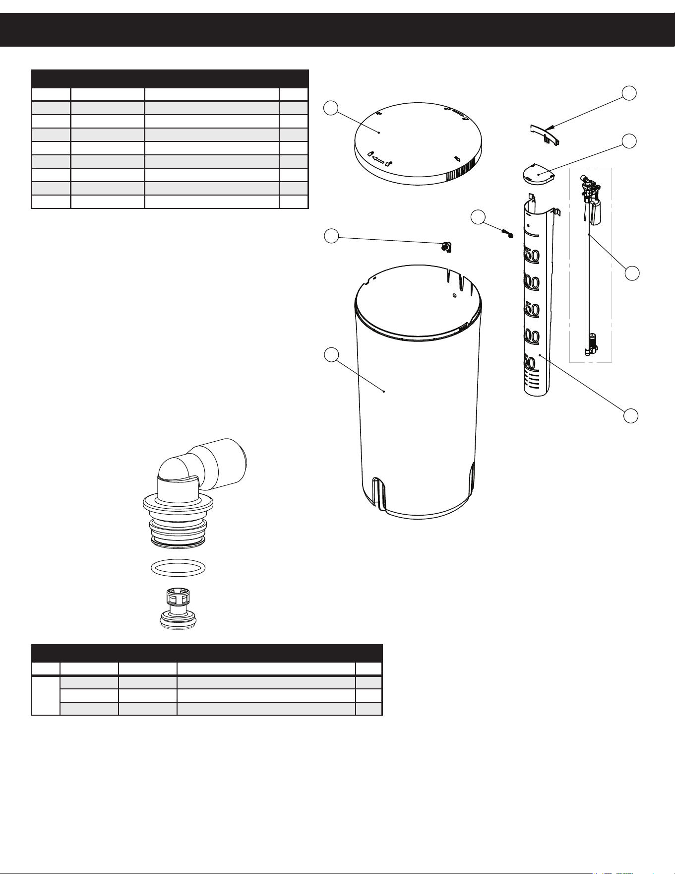
SAFETY FLOAT BRINE ELBOW
Item # Legacy Part # Current Part # Description Qty.
CV4144 100245015 3/8” elbow cap, Parker fitting (no flow control) 1
CV4144-03 100242646 3/8” elbow cap, Parker fitting (w/flow control) 1
CH4612 100245861 1/2” elbow cap 1
1
2
7
8
6
3
5
4
ITEM #
PART #
DESCRIPTION
QTY.
1 100379336
18" x 36" BRINE TANK
1
2 100379337
BRINE TANK LID
1
3 100379338
BRINE WELL
1
4 100399465
SAFETY SHUTOFF ASSEMBLY,
0.5 GPM
1
5 100245864
SAFETY SHUTOFF NUT
1
6 100379339
BRINE WELL COVER
1
7 100397461
BRINE TANK GROMMET
1
8 100238195
CABINET OVERFLOW ELBOW
1
BRINE TANK ASSEMBLY
Item # Current Part # Description Qty.
1 100379336 19” x 37” Brine tank 1
2 100379337 Brine tank lid 1
3 100379338 Brine well 1
4 100399465 Safety shutoff assembly, 0.5 gpm 1
5 100245864 Safety shutoff nut 1
6 100379339 Brine well cover 1
7 100397461 Brine well retainer 1
8 100238195 Cabinet overflow elbow 1
30
Replacement Parts
BRINE TANK ASSEMBLIES
Part # Description Qty.
AOBT1937-1A 19x37 BRINE TANK ASSEMBLY 1
BT1840-1A 18x40 BT ASSY 3/8 BRINE LINE 1
BT1840-2A 18x40 BT ASSY 1/2 BRINE LINE 1
BT2441-1A 24x41 BT ASSY 3/8 BRINE LINE 1
BT2441-2A 24x41 BT ASSY 1/2 BRINE LINE 1
BT2450-1A 24x50 BT ASSY 3/8 BRINE LINE 1
BT2450-2A 24x50 BT ASSY 1/2 BRINE LINE 1
BT3050-2A 30x50 BT ASSY 1/2 BRINE LINE 1
BT3050-3A 30x50 BT ASSY 3/4 OR 1 BRINE CONNECTION 1
BT3948-2A 39x48 BT ASSY 1/2 BRINE LINE 1
BT3948-3A 39x48 BT ASSY 3/4 OR 1 BRINE CONNECTION 1
BT5060-2A 50x60 BT ASSY 1/2 BRINE LINE 1
BT5060-3A 50x60 BT ASSY 3/4 OR 1 BRINE CONNECTION 1
INTERNAL BRINE TANK ASSEMBLIES
(INCLUDES SAFETY FLOAT, BRINE LINE, WELL & CAP, OVERFLOW)
Part # Description Qty.
BT1840-1-GUTS 18x40 BRINE TANK INTERNAL ASSY KIT 3/8" 1
BT1840-2-GUTS 18x40 BRINE TANK INTERNAL ASSY KIT 1/2" 1
BT2441-1-GUTS 24x41 BRINE TANK INTERNAL ASSY KIT 3/8" 1
BT2441-2-GUTS 24x41 BRINE TANK INTERNAL ASSY KIT 1/2" 1
BT2450-1-GUTS 24x50 BRINE TANK INTERNAL ASSY KIT 3/8" 1
BT2450-2-GUTS 24x50 BRINE TANK INTERNAL ASSY KIT 1/2" 1
BT3050-2-GUTS 30x50 BRINE TANK INTERNAL ASSY KIT 1/2" 1
REPLACEMENT PARTS
BRINE TANK COMPONENTS
Part # Description Qty.
CH4700-
36.5WR-1
SAFTEY SHUT BRINE ASSY W/ FLOAT AND AIR
CHECK 3/8 18X40 AND 24X41 BT
1
CH4600-50 474 SAFTEY SHUT OFF 3/8" ELBOW 1
CH4600-02 474 SAFTEY SHUT OFF 1/2" ELBOW 1
CH4500-48 474 AIR CHECK 1/2" X 48" 1
CH4900 494 BRINE ASSY 3/4" OR 1" ELBOW 1
CH1030-36S SLOTTED BRINE WELL 4"X36" 1
CH7016 4" BRINE WELL COVER 1
CH1033-48S SLOTTED BRINE WELL 5"X48" 1
CH1017 5" BRINE WELL COVER 1
CH4640-32 474 FLOAT ASSY W/ 2 GROMMETS 1
CH1018 2 PIECE OVERFLOW SET 1
CH1072-01 18" GRID PLATE 1
CH1080 24" GRID PLATE SET 1
CH1032 30" GRID PLATE SET 1
BSA-3923-05* 39" GRID PLATE ASSY 1
SAFETY FLOAT BRINE ELBOW
Part # Description Qty.
CH4651-050 474 .5 gpm flow control 1
CV3163 O-Ring 019 1
CV4144 3/8” elbow cap, Parker fitting 1
CH4612 1/2” elbow cap 1
CH4615 Elbow locking clip 1
CH4612 Regenerant Elbow with Flow Control 1
CJCPG-8PBLK Nut, Compression 1/2" Black 1
*Contact Technical Service for specifi c build.
1” PVC MALE NPT ELBOW
Item Part No. Description Qty.
CV3007 1” PVC male NPT elbow assembly 2
4 CV3149 Fitting 2
3/4” BRASS SWEAT
Item Part No. Description Qty.
CV3007-03 3/4” brass sweat assembly 2
4 CV3188-01 Fitting 2
1-1/4” & 1-1/2” BRASS SWEAT
Item Part No. Description Qty.
CV3007-09 1-1/4” & 1-1/2” brass sweat assembly 2
4 CV3375 Fitting 2
1” BRASS SHARK BITE
Item Part No. Description Qty.
CV3007-13 1” brass shark bite assembly 2
4 CV3629 Fitting 2
3/4” JOHN GUEST ELBOW
Item Part No. Description Qty.
CV3007-15 3/4” john guest elbow assembly 2
4 CV3790 Fitting 2
1” JOHN GUEST
Item Part No. Description Qty.
CV3007-17 1” john guest assembly 2
4 CV4045 Fitting 2
1-1/4” & 1-1/2” PVC SOLVENT
Item Part No. Description Qty.
CV3007-07 1-1/4” & 1-1/2” PVC solvent assembly 2
4 CV3352 Fitting 2
3/4 BRASS SHARK BITE
Item Part No. Description Qty.
CV3007-12 3/4” brass shark bite assembly 2
4 CV3628 Fitting 2
1” PLASTIC MALE NPT
Item Part No. Description Qty.
CV3007-04 1” plastic male NPT assembly 2
4 CV3164 Fitting 2
1-1/4” PLASTIC MALE NPT
Item Part No. Description Qty.
CV3007-05 1-1/4” plastic male assembly 2
4 CV3317 Fitting 2
3/4” & 1” PVC SOLVENT ELBOW
Item Part No. Description Qty.
CV3007-01 3/4” & 1” PVC solvent elbow assembly 2
4 CV3189 Fitting 2
1” BRASS SWEAT
Item Part No. Description Qty.
CV3007-02 1” brass sweat assembly 2
4 CV3188 Fitting 2
Item No. Part No. Description Qty.
1 CV3151 Nut, 1” quick connect 2
2 CV3150 Split ring 2
3 CV3105 O-ring 215 2
NOTE: Not all available fi ngs are
displayed below. Contact
manufacturer for op onal
fi ngs.
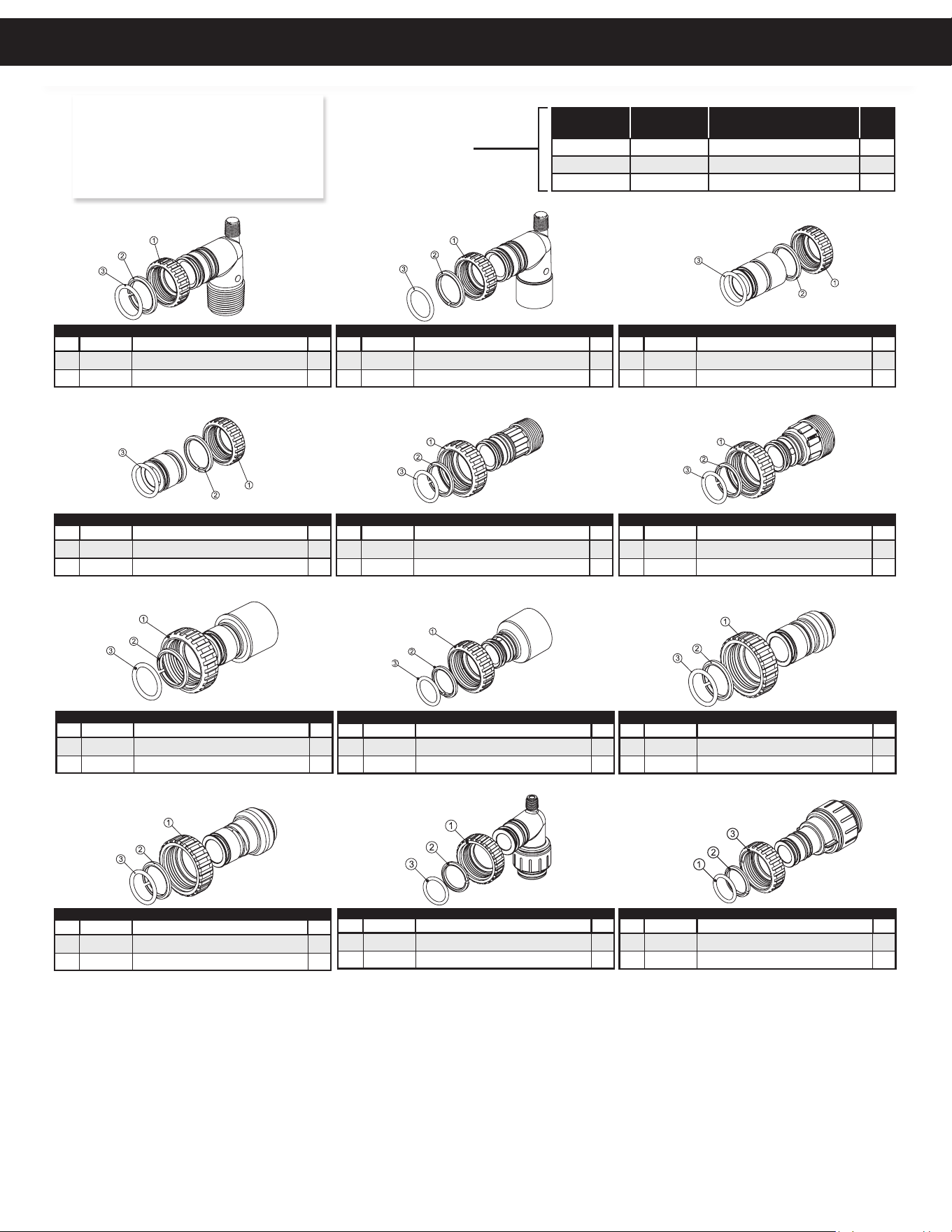
INSTALLATION FITTING ASSEMBLIES
For All Assemblies
31
1” PVC MALE NPT ELBOW
Item Part No. Description Qty.
CV3007 1” PVC male NPT elbow assembly 2
4 CV3149 Fitting 2
3/4” BRASS SWEAT
Item Part No. Description Qty.
CV3007-03 3/4” brass sweat assembly 2
4 CV3188-01 Fitting 2
1-1/4” & 1-1/2” BRASS SWEAT
Item Part No. Description Qty.
CV3007-09 1-1/4” & 1-1/2” brass sweat assembly 2
4 CV3375 Fitting 2
1” BRASS SHARK BITE
Item Part No. Description Qty.
CV3007-13 1” brass shark bite assembly 2
4 CV3629 Fitting 2
3/4” JOHN GUEST ELBOW
Item Part No. Description Qty.
CV3007-15 3/4” john guest elbow assembly 2
4 CV3790 Fitting 2
1” JOHN GUEST
Item Part No. Description Qty.
CV3007-17 1” john guest assembly 2
4 CV4045 Fitting 2
1-1/4” & 1-1/2” PVC SOLVENT
Item Part No. Description Qty.
CV3007-07 1-1/4” & 1-1/2” PVC solvent assembly 2
4 CV3352 Fitting 2
3/4 BRASS SHARK BITE
Item Part No. Description Qty.
CV3007-12 3/4” brass shark bite assembly 2
4 CV3628 Fitting 2
1” PLASTIC MALE NPT
Item Part No. Description Qty.
CV3007-04 1” plastic male NPT assembly 2
4 CV3164 Fitting 2
1-1/4” PLASTIC MALE NPT
Item Part No. Description Qty.
CV3007-05 1-1/4” plastic male assembly 2
4 CV3317 Fitting 2
3/4” & 1” PVC SOLVENT ELBOW
Item Part No. Description Qty.
CV3007-01 3/4” & 1” PVC solvent elbow assembly 2
4 CV3189 Fitting 2
1” BRASS SWEAT
Item Part No. Description Qty.
CV3007-02 1” brass sweat assembly 2
4 CV3188 Fitting 2
Item No. Part No. Description Qty.
1 CV3151 Nut, 1” quick connect 2
2 CV3150 Split ring 2
3 CV3105 O-ring 215 2
NOTE: Not all available fi ngs are
displayed below. Contact
manufacturer for op onal
fi ngs.
INSTALLATION FITTING ASSEMBLIES
For All Assemblies
Installation Fiing Assemblies

32
This page intentionally left blank.

33
A. O. Smith Commercial Limited Warranty
WHO IS COVERED
This limited warranty is provided by A. O. Smith and applies only to the original owner who purchased and installed the A. O. Smith product for
use at the original installa on site. This warranty is non-transferable.
WHAT IS COVERED
This warranty covers defects in materials or workmanship in your A. O. Smith product when properly installed, used under normal opera ng
condi ons, and maintained according to A. O. Smith guidelines and local plumbing codes.
WARRANTY COVERAGE PERIODS
All warranty coverage periods run from the date of purchase, or 60 days a er the date of manufacture if the purchase date cannot be verifi ed.
For a period of FIVE YEARS: The control valve and all internal components.
The salt storage container.
Fiberglass mineral tank except damages due to freezing, high pressure (120 psi and above), extreme
temperature (100°F and above) or a vacuum on the system.
For a period of ONE YEAR: All other so ener components.
This warranty does not cover any equipment purchased for use in applica ons in which the product is not suited. It is the responsibility of the
buyer to determine if a product is suitable for a par cular applica on.
WHAT A. O. SMITH WILL DO
If a component is found defec ve during its warranty period, A. O. Smith will repair or replace the defec ve part at its discre on with an iden cal
part or a comparable part if an iden cal replacement is not available. The owner is responsible for freight charges from the factory and local
dealer service or labor fees. The warranty period for any replacement will run for the balance of the original warranty period.
WHAT A. O. SMITH WILL NOT DO
A. O. Smith will not pay for labor to remove or reinstall parts, shipping damage, water damage resul ng from system failure, dealer trip charges,
unauthorized service, damage caused by failure to follow installa on instruc ons, or replacement fi lters, media, or rou ne maintenance.
WHAT IS NOT COVERED
1. This warranty does not cover: damage caused by accident, misuse, neglect, fi re, fl ood, freezing, or other acts of God, improper
installa on, altera on, vacuum damage, chemicals, opera on outside specifi ca ons, cosme c issues, non-A. O. Smith parts,
installa on costs, improper plumbing connec ons, lack of maintenance, use with water that is microbiologically unsafe, loss of use,
property damage, incidental or consequen al damages, freight, or water damage. A. O. Smith disclaims all implied warran es to the
fullest extent permi ed by law.
2. Except when specifi cally prohibited by the applicable state law, the Owner, and not the Manufacturer, shall be liable for and shall pay
for all charges for labor or other expenses incurred in the removal, repair or replacement of any component part(s) claimed to be
defec ve or any expense incurred to remedy any defect in the product. Such charges may include, but are not necessarily limited to:
a. All freight, shipping, handling and delivery costs of forwarding a new component or replacement part(s) to the owner.
b. All costs necessary or incidental in removing the defec ve component part(s) and installing a new component part(s).
c. Any material required to complete, and/or permits required for, installa on of a new component or replacement part(s).
d. All costs necessary or incidental in returning the defec ve component part(s) to a loca on designated by the Manufacturer.
e. This warranty provides specifi c legal rights and limita ons, but you may have other rights under applicable state law.
OWNER RESPONSIBILITIES
Owners must install and operate the system per A. O. Smith specifi ca ons, comply with local codes, prevent freezing or vacuum damage,
operate within pressure/temperature limits, replace media/fi lters as required, use only approved components, and retain proof of purchase and
installa on date. Either proof of purchase from an authorized dealer or proof of serial number, along with proof of proper installa on, will be
required to obtain warranty coverage.
HOW TO OBTAIN SERVICE
If service is required, contact your installa on dealer or an authorized A. O. Smith dealer. If unavailable, ship the defec ve component (freight
prepaid) to: A. O. Smith, 1000 Prospect Ct., Appleton, WI 54914. A. O. Smith will return repaired or replaced parts freight collect. Registra on is
not required to be covered by this warranty.
LIMITATION OF REMEDIES
The owner’s sole remedy is repair or replacement of defec ve parts. A. O. Smith is not liable for incidental, consequen al, water, or property
damages. Some states do not allow such limita ons; in such states, these may not apply.
STATE LAW RIGHTS
This warranty provides specifi c legal rights; addi onal rights may vary by state.
© 2026 A. O. Smith, Inc. All rights reserved.
A. O. Smith Commercial
Limited Warranty

34
This page intentionally left blank.

35
This page intentionally left blank.

1900 Prospect Court • Appleton, WI 54914
Phone: 920-739-9401 • Fax: 920-739-9406
© 2021 A. O. Smith, Inc. All rights reserved.
REV0326 - 100243291 - 2000630092