1
OPERATION MANUAL AND
INSTALLATION INSTRUCTIONS
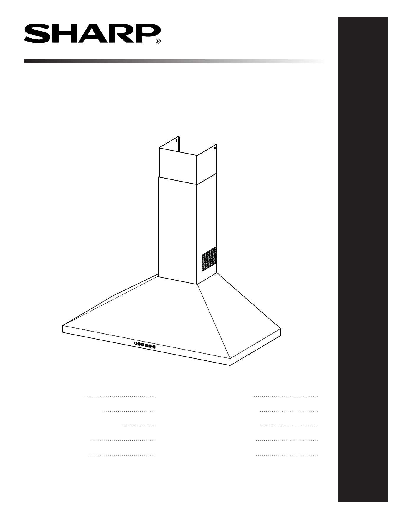
WALL-MOUNT CHIMNEY RANGE HOOD
MODELS: SHC2443SNS/ SHC3043SNS/ SHC3063SNS/
SHC3063KNS/ SHC3663SNS
V
Range Hood Models: SHC2443SNS/ SHC3043SNS/ SHC3063SNS/
SHC3063KNS/ SHC3663SNS
CUSTOMER ASSISTANCE
CONSUMER LIMITED WARRANTY
BEFORE INSTALLING THE RANGE HOOD
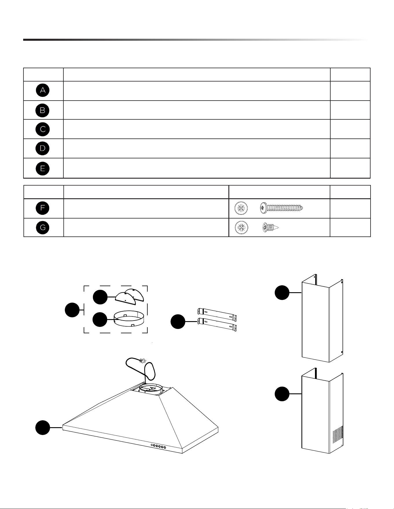
RANGE HOOD DIMENSIONS
RANGE HOOD MAIN PARTS
PRODUCT SPECIFICATIONS
MEASURE THE INSTALLATION
INSTALLATION INSTRUCTIONS
OPERATING THE CONTROLS
CLEANING & MAINTENANCE
2
3
4-6
7
8-9
10
11
12-15
16-17
18-19
2
CUSTOMER ASSISTANCE
UNITED STATES ONLY
REGISTER YOUR PRODUCT
Registering your new product is easy and offers benets that help you get the most
out of your Sharp product including:
9 Convenience: Ifyoueverneedwarrantysupport,yourproductinformationisalreadyonle.
9 Communication:StayuptodatewithimportantnoticationsandspecialoffersfromSHARP.
9 Support: Quickly access support content including Owner’s Manuals, FAQ’s,
How-toVideos,andmuchmore.
3 EASY WAYS TO REGISTER TODAY!
PRODUCT SUPPORT
If you have questions about the setup or operation of your product, please refer to
the corresponding section within this manual.
Additionally, visit www.sharpusa.com/support to access exclusive content about your
product including:
Æ FAQ’s and How-To Videos
Æ Find or Request Service
Æ Purchase an Extended Warranty
Æ Downloads including the Installation Guide, Spec Sheet, and Owner’s Manual
CONTACT US
If at any time you have questions or comments concerning your SHARP product,
please contact the SHARP Customer Assistance Center. We are available to
assist you through multiple contact methods for your convenience:
Scan this QR Code on your smart phone Visit http://www.sharpusa.com/register
ONLINE
Visit our sites to
learn more about
your product at
sharpusa.com and
sbl.sharpusa.com
See the Contact Us section on our sites U.S. | www.sharpusa.com/support Contact a Sharp Advisor on the phone
Contact a Sharp Advisor on the phone
CALL US
US 800-BE-SHARP
800-237-4277
CALL US
US 800-BE-SHARP
800-237-4277
EMAIL
Available 24/7
US: sharpusa.com
CHAT ONLINE
SCAN
Use the camera or
QR code scanning
application on your
smart phone
2

3
CONSUMER LIMITED WARRANTY
SHARP ELECTRONICS CORPORATION warrants to the rst consumer purchaser that this Sharp brand product (the “Product”),
when shipped in its original container, will be free from defective workmanship and materials, and agrees that it will, at its option,
either repair the defect or replace the defective Product or part thereof with a new or remanufactured equivalent at no charge to the
purchaser for parts or labor for the period(s) set forth below.
This warranty does not apply to any cosmetic or appearance items of the Product nor to the additional excluded item(s) set forth below
nor to any Product the exterior of which has been damaged or defaced, which has been subjected to misuse, abnormal service or
handling, or which has been altered or modied in design or construction. In order to enforce the rights under this limited warranty,
the purchaser should follow the steps set forth below and provide proof of purchase to the servicer.
The limited warranty described herein is in addition to whatever implied warranties may be granted to purchasers by law. ALL IMPLIED
WARRANTIES INCLUDING THE WARRANTIES OF MERCHANTABILITY AND FITNESS FOR USE ARE LIMITED TO
THE PERIOD(S) FROM THE DATE OF PURCHASE SET FORTH BELOW. Some states do not allow limitations on how long an
implied warranty lasts, so the above limitation may not apply to you.
Neither the sales personnel of the seller nor any other person is authorized to make any warranties other than those described herein,
or to extend the duration of any warranties beyond the time period described above on behalf of Sharp. The warranties described
herein shall be the sole and exclusive warranties granted by Sharp and shall be the sole and exclusive remedy available to the purchaser.
Correction of defects, in the manner and for the period of time described herein, shall constitute complete fulllment of all liabilities
and responsibilities of Sharp to the purchaser with respect to the Product, and shall constitute full satisfaction of all claims, whether
based on contract, negligence, strict liability or otherwise. In no event shall Sharp be liable, or in any way responsible, for any damages
or defects in the Product which were caused by repairs or attempted repairs performed by anyone other than an authorized servicer.
Nor shall Sharp be liable or in any way responsible for any incident or consequential economic or property damage. Some states do
not allow the exclusion of incidental or consequential damages, so the above exclusion may not apply to you.
THIS LIMITED WARRANTY IS VALID ONLY IN THE FIFTY (50) UNITED STATES, THE DISTRICT OF COLUMBIA AND
PUERTO RICO.
Product model number &
description:
SHC2443SNS, SHC3043SNS, SHC3063SNS, SHC3063KNS or SHC3663SNS Range Hood
Warranty period for this product:
One (1) year parts and labor, including in-home service.
Additional item(s) excluded from
warranty coverage:
Commercial, non-residential, or use inconsistent with published installation and product
operational instructions.
Light bulbs and lters.
In home instruction on how to use your product.
What to do to obtain service:
In-home service is provided for one year from date of purchase. Service can be arranged by
calling 1-800-BE-SHARP. Be sure to have Proof of Purchase, Model, and Serial Number
available.
TO OBTAIN SUPPLY, ACCESSORY OR PRODUCT INFORMATION, CALL 1-800-BE-SHARP or visit www.sharpusa.com.
SAVE THE PROOF OF PURCHASE AS IT IS NEEDED SHOULD YOUR RANGE HOOD EVER REQUIRE WARRANTY
SERVICE.

4
BEFORE INSTALLING THE RANGE HOOD
READ AND SAVE THESE INSTRUCTIONS TO REDUCE THE RISK
OF FIRE, ELECTRIC SHOCK, OR INJURY TO
PERSON(S) OBSERVE THE FOLLOWING:
1 Use this unit only in the manner intended by the manufacturer. If
you have questions, contact the manufacturer at the address
or telephone number listed in the warranty.
2 Before servicing or cleaning unit, switch power off at service
panel and lock service disconnecting means to prevent power
from being switch on accidentally. When the service
disconnecting means cannot be locked, securely fasten a
prominent warning device, such as a tag, to the service panel.
3 Installation work and electrical wiring must be done by qualied
personnel in accordance with all applicable codes and standards,
including re-rated construction codes and standards.
4 Sufcient air is needed for proper combustion and exhausting of
gases through the ue (chimney) of fuel burning equipment to
prevent backdrafting. Follow the heating equipment
manufacturer’s guidelines and safety standards such as those
published by the National Fire Protection Association (NFPA),
the American Society for Heating, Refrigeration and Air
Conditioning Engineers (ASHRAE) and the local
code authorities.
5 This product may have sharp edges. Be careful to avoid cuts and
abrasions during installation or cleaning.
6 When cutting or drilling into wall or ceiling, do not damage
electrical wiring and other hidden utilities.
7 Ducted fans used to exhaust contaminants must always be vent-
ed to the outdoors
8 Do not use this unit with any other solid-state speed
control device.
9 Use only metal ductwork.
10 This unit must be grounded.
TO REDUCE THE RISK OF A RANGE TOP GREASE FIRE:
1 Never leave surface units unattended at high settings. Boilovers
cause smoking and greasy spillovers that may ignite. Heat oils
slowly on low or medium settings.
2 Always turn hood ON when cooking at high heat or when
cooking aming foods (i.e. Crêpes Suzette, Cherries Jubilee,
Peppercorn Beef Flambé). (In USA only)
3 Clean ventilating fans frequently. Grease should not be allowed
to accumulate on fan or lters.
4 Use proper pan size. Always use cookware appropriate for the
size of the surface element.
WARNING TO REDUCE THE RISK OF INJURY TO
PERSON(S) IN THE EVENT OF A RANGE TOP GREASE FIRE,
OBSERVE THE FOLLOWING*:
1 SMOTHER FLAMES with a close-tting lid, cookie sheet, or
metal tray, then turn off the burner. BE CAREFUL TO
PREVENT BURNS. IF THE FLAMES DO NOT GO OUT
IMMEDIATELY, EVACUATE AND CALL THE
FIRE DEPARTMENT.
2 NEVER PICK UP A FLAMING PAN – You may be burned.
3 DO NOT USE WATER, including wet dishcloths or towels –
This could cause a violent steam explosion.
4 Use an extinguisher ONLY if:
A You know you have a Class ABC extinguisher and you
know how to operate it.
B The re is small and contained in the area where it started.
C The re department has been called.
D You can ght the re with your back to an exit.
*Based on “Kitchen Fire Safety Tips” published by NFPA.
CAUTION
1 For indoor non-commercial use only.
2 For general ventilating use only. Do not use to exhaust
hazardous or explosive materials and vapors.
3 To avoid motor bearing damage and noisy and/or unbalanced
impeller, keep drywall spray, construction dust, etc. off
power unit.
4 Do not use over cooking equipment greater than 60,000 BTU/
hr. as the blower motor will shut down intermittently.
5 Your hood motor has a thermal overload which will
automatically shut off the motor if it becomes overheated. The
motor will restart when it cools down. If the motor continues
to shut off and restart, have the hood serviced.
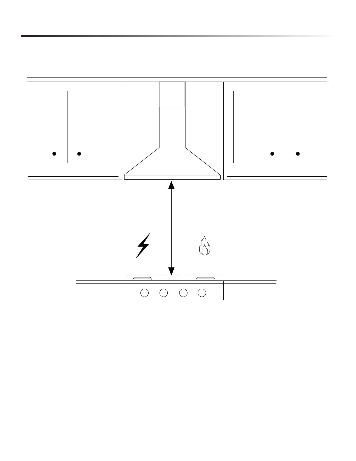
6 The bottom of the hood MUST NOT BE LESS than 24” for
ELECTRIC COOKTOP and 30” over GAS and recommend
a maximum of 36” above cooktop for best capture of cooking
impurities.
7 Two installers are recommended because of the size of
this hood.
8 To reduce risk of re and to properly exhaust air, be sure to
duct air outside. Do not exhaust air into spaces within walls or
ceilings or into attics, crawl spaces, or garages. Ducted fans
used to exhaust contaminants must always be vented to the
outdoors
9 Be careful when installing the decorative ue and hood, they
may have sharp edges.
10 Accessible parts may become hot when used with cooking
appliances.
11 This appliance is not intended for use by persons (including
children) with reduced physical, sensory or mental capabili-
ties, or lack of experience and knowledge, unless they have
been given supervision or instruction concerning use of the
appliance by a person responsible for their safety.
5
INSTALLER: LEAVE THIS GUIDE WITH THE
HOMEOWNER.
HOMEOWNER: OPERATION AND MAINTENANCE
INFORMATIONS ARE ON PAGES 16-19.
WARNING Cancer and Reproductive Harm -
www.P65Warnings.ca.gov
BEFORE INSTALLING THE RANGE HOOD
12 Children should be supervised to ensure that they do not play with
the appliance.
13 There shall be adequate ventilation of the room when the range
hood is used at the same time as appliances burning gas or other
fuels (not applicable to appliances that only discharge the air back
into the room).
14 Do not ame food under the range hood.
15 Always turn hood ON when cooking at high heat or when
ambeing food (i.e. Crepes Suzette, Cherries Jubilee, Peppercorn
Beef Flambe’) (in USA only).
16 There is a re risk if cleaning is not carried out in accordance
with the instructions.
17 The air must not be discharged into a ue that is used for
exhausting fumes from appliances burning gas or other fuels
(not applicable to appliances that only discharge the air back into
the room).
18 Regulations concerning the discharge of air have to be fullled.
19 Means for disconnection must be incorporated in the xed wiring
in accordance with the wiring rules.
20 The disconnection may be achieved by incorporating a switch in
the xed wiring in accordance with the wiring rules.
21 The disconnection may be achieved by having the plug accessible
or by incorporating a switch in the xed wiring in accordance with
the wiring rules.
22 This appliance must be grounded. In the event of an electrical short
circuit, grounding reduces the risk of electric shock by providing
an escape wire for the electric current. If this appliance is equipped
with a cord having a grounding wire with a grounding plug, the
plug must be plugged into an outlet that is properly installed and
grounded.
23 Please read specication label on product for further
information and requirements.
WARNING
Improper grounding can result in a risk of electric
shock. Consult a qualied electrician if the grounding instructions are
not completely understood, or if doubt exists as to whether the
appliance is properly grounded.
WARNING
To Reduce The Risk Of Fire, Electric Shock Or Injury
To Persons, Do Not Use Replacement Parts That Have Not Been
Recommended By The Manufacturer (e.g. Parts Made At Home Using
A 3D Printer).
ALL WALL AND FLOOR OPENINGS WHERE THE
RANGE HOOD IS INSTALLED MUST BE SEALED.
This Range Hood requires at least 24” of clearance between the
bottom of the Range Hood and the cooking surface or countertop.
This hood has been approved by UL at this distance from the
cooktop.
This minimum clearance may be higher depending on local
building codes. For gas cooktops and combination ranges,
a minimum of 30” is recommended and may be required.
Overhead cabinets on both sides of this unit must be a minimum
of 18” above the cooking surface or countertop. Consult the
cooktop or range installation instructions given the manufacturer
before making any cutouts.
MOBILE HOME INSTALLATION
The installation of this Range Hood must conform to the
Manufactured Home Construction and Safety Standards, Title
24 CFR, Part 3280 (formerly Federal Standard for Mobile Home
Construction and Safety, Title 24, HUD, Part 280). See Electrical
Requirements.
VENTING REQUIREMENTS
Determine which venting method is best for your application.
Ductwork can extend either through the wall or the roof. The
length of the ductwork and the number of elbows should be kept
to a minimum to provide efcient performance. The size of the
ductwork should be uniform. Do not install two elbows together.
Use duct tape to seal all joints in the ductwork system.
Use caulking to seal exterior wall or ooring opening around the
cap.
Flexible ductwork is not recommended. Flexible ductwork
creates back pressure and air turbulence that greatly reduces
performance.
Make sure there is proper clearance within the wall or oor for
exhaust duct before making cutouts. Do not cut a joist or stud
unless absolutely necessary. If a joist or stud must be cut, then a
supporting frame must be constructed.
COLD WEATHER INSTALLATIONS
An additional back draft damper should be installed to minimize
backward cold air ow and a nonmetallic thermal break should be
installed to minimize conduction of outside temperatures as part of
the vent system. The damper should be on the cold air side of the
thermal break. The break should be as close as possible to where
the vent system enters the heated portion of the house.
WARNING
• Venting system MUST terminate outside the home.
• DO NOT terminate the ductwork in an attic or other
enclosed space.
• DO NOT use 4” laundry-tape wall caps.
• Flexible-type ductwork is not recommended.
• DO NOT obstruct the ow of combustion and
ventilation air.
• Failure to follow venting requirements may result in a
re.
6
BEFORE INSTALLING THE RANGE HOOD
WARNING
• Electrical ground is required on this Range Hood.
• If cold water pipe is interrupted by plastic, nonmetallic
gaskets or other materials, DO NOT use for grounding.
• DO NOT ground to a gas pipe.
• DO NOT have a fuse in the neutral or grounding circuit.
A fuse in the neutral or grounding circuit could result in
electrical shock.
• Check with a qualied electrician if you are in doubt as to
whether the Range Hood is properly grounded.
• Failure to follow electrical requirements may result in
severe consequences, including fatal electrocution,
serious burns, and widespread property damage
from res.
ELECTRICAL REQUIREMENTS
A 120 volt, 60 Hz AC-only electrical supply is required on a
separate 15 amp fused circuit. A time-delay fuse or circuit breaker
is recommended. The fuse must be sized per local codes in
accordance with the electrical rating of this unit as specied on
the serial/rating plate located inside the unit near the eld wiring
compartment.
7
RANGE HOOD DIMENSIONS
8
RANGE HOOD MAIN PARTS
PARTS INCLUDED
REF. PART
Hood body - Includes Controls, Light, Filters, Blower 1
Metal Ring with Flaps 1
Lower Chimney 1
Upper Chimney 1
Chimney Wall Brackets 2
REF. PART
Pozi Screws (3/16” x 1 3/4”) 8
Pozi Screws (1/8” x 3/8”) 4
9
PARTS
REF. PART
A Hood body – Includes Controls, Light, Filters, Blower 1
B Metal Ring with Flaps 1
C Lower Chimney 1
D Upper Chimney 1
E Chimney wall brackets 2
REF
PART
F
Pozi Screws (3/16" x 1 3/4")
8
G Pozi Screws (1/8" x 3/8")
4
PARTS INCLUDED
D
A
C
E
B
x
y
9
RANGE HOOD MAIN PARTS
PART
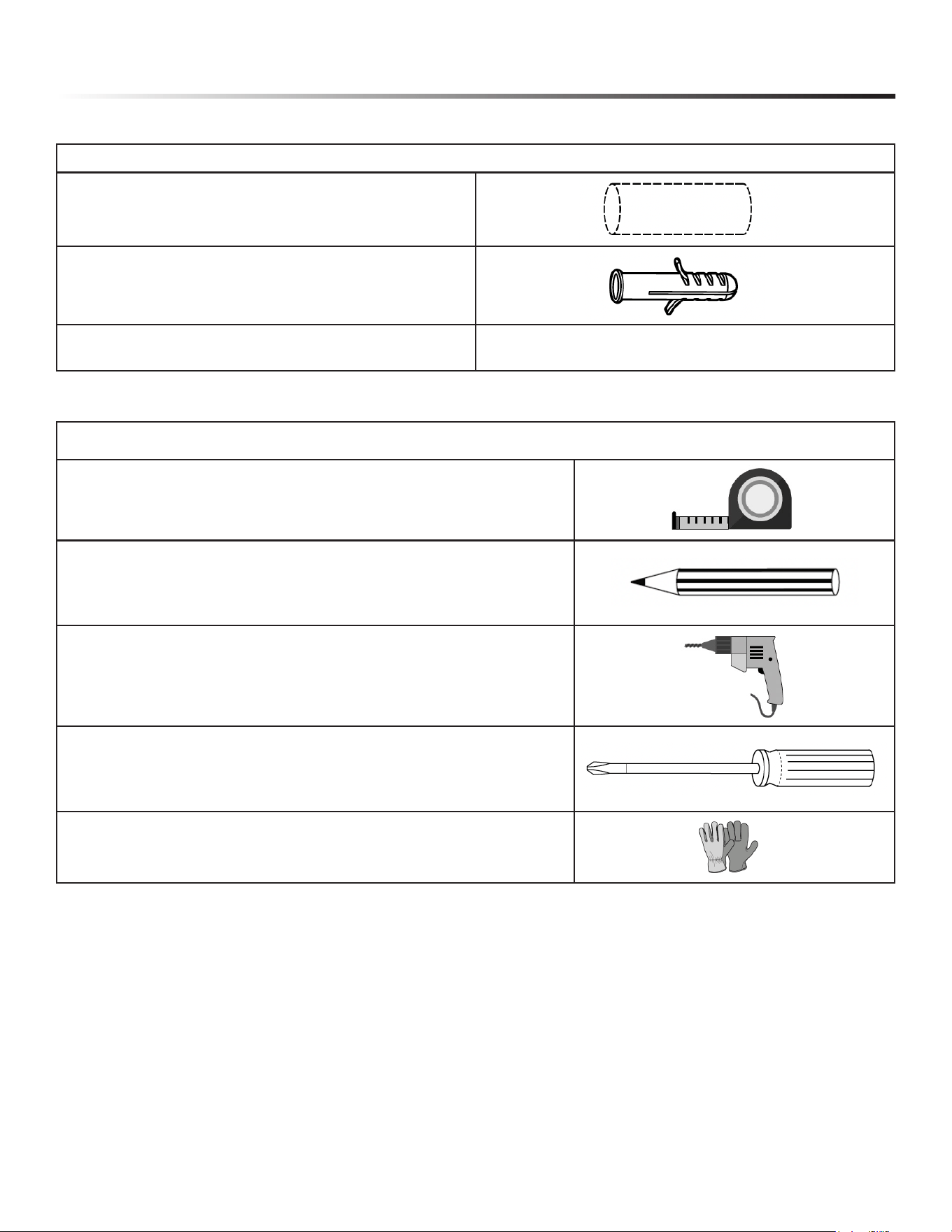
6” Round Metal Ductwork
Drywall plugs or other suitable wall fasteners based on
your installation.
Wall Cap/Roof Cap Needs to be purchased separately.
PARTS NEEDED
TOOL
Tape Measure
Pencil
Electric Drill with 5/16” Drill Bit
Pozi Screwdriver
Work gloves
TOOLS NEEDED
10
PRODUCT SPECIFICATIONS
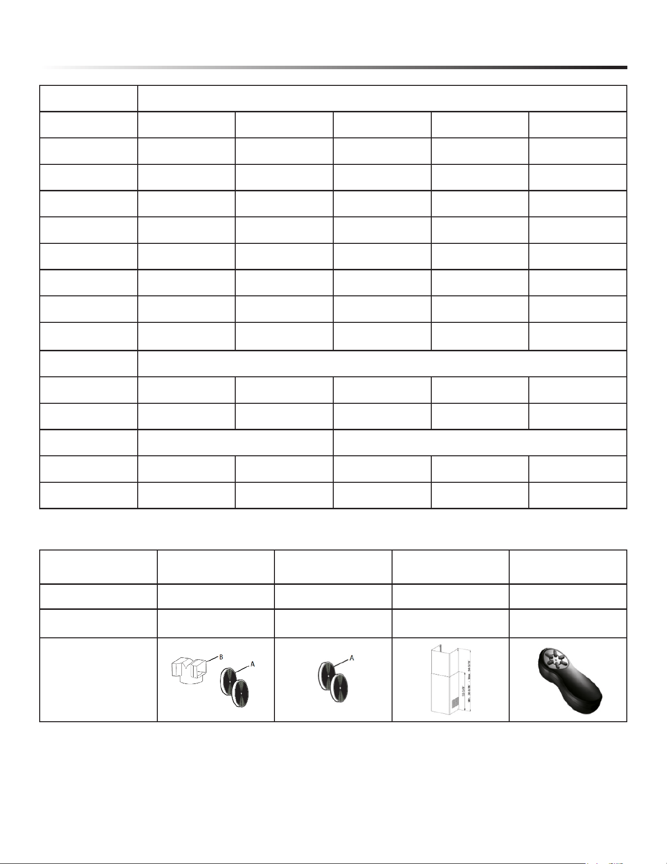
ITEM MODELS
SHC2443SNS SHC3043SNS SHC3063SNS SHC3063KNS SHC3663SNS
Finish Stainless Steel Stainless Steel Stainless Steel Stainless Steel Stainless Steel
Power Requirements 120V 60Hz 120V 60Hz 120V 60Hz 120V 60Hz 120V 60Hz
Dimensions
Width 23-9/16” 29-15/16” 29-15/16” 29-15/16” 35-3/8”
Height Min. 34-11/16” 34-11/16” 34-11/16” 34-11/16” 34-11/16”
Max. 48-7/16” 48-7/16” 48-7/16” 48-7/16” 48-7/16”
Depth 18-1/2” 18-1/2” 18-1/2” 18-1/2” 18-1/2”
Control Electronic Electronic
Electronic with
Backlight
Electronic with
Backlight
Electronic with
Backlight
Lamps Round LED bulb GU10 x 2
Blower Power 400 CFM 400 CFM 600 CFM 600 CFM 600 CFM
Speeds 3 Speeds + Boost 3 Speeds + Boost 3 Speeds + Boost 3 Speeds + Boost 3 Speeds + Boost
CFM Adjustability N.A. CFM Adjustable Platform (CAP)
Delay Off No No Yes Yes Yes
Safety Standard UL UL UL UL UL
AVAILABLE ACCESSORIES
Accessories
Ductless Conversion Kit
(incl. Charcoal Filters)
Charcoal Filter
Replacement
Extension Flue Remote Control Unit
Model Number SKCH63DLK SKCH63CFL SKCH63EXF SKCH63RHU
UPC Code 074000623156 074000623163 074000623170 074000623187
Product
11
MEASURE THE INSTALLATION
8
MIN. 24" OVER ELECTRIC / MIN. 30" OVER GAS
INSTALLATION HEIGHT REQUIREMENTS
Min. 30"Min. 24"
12
INSTALLATION INSTRUCTIONS
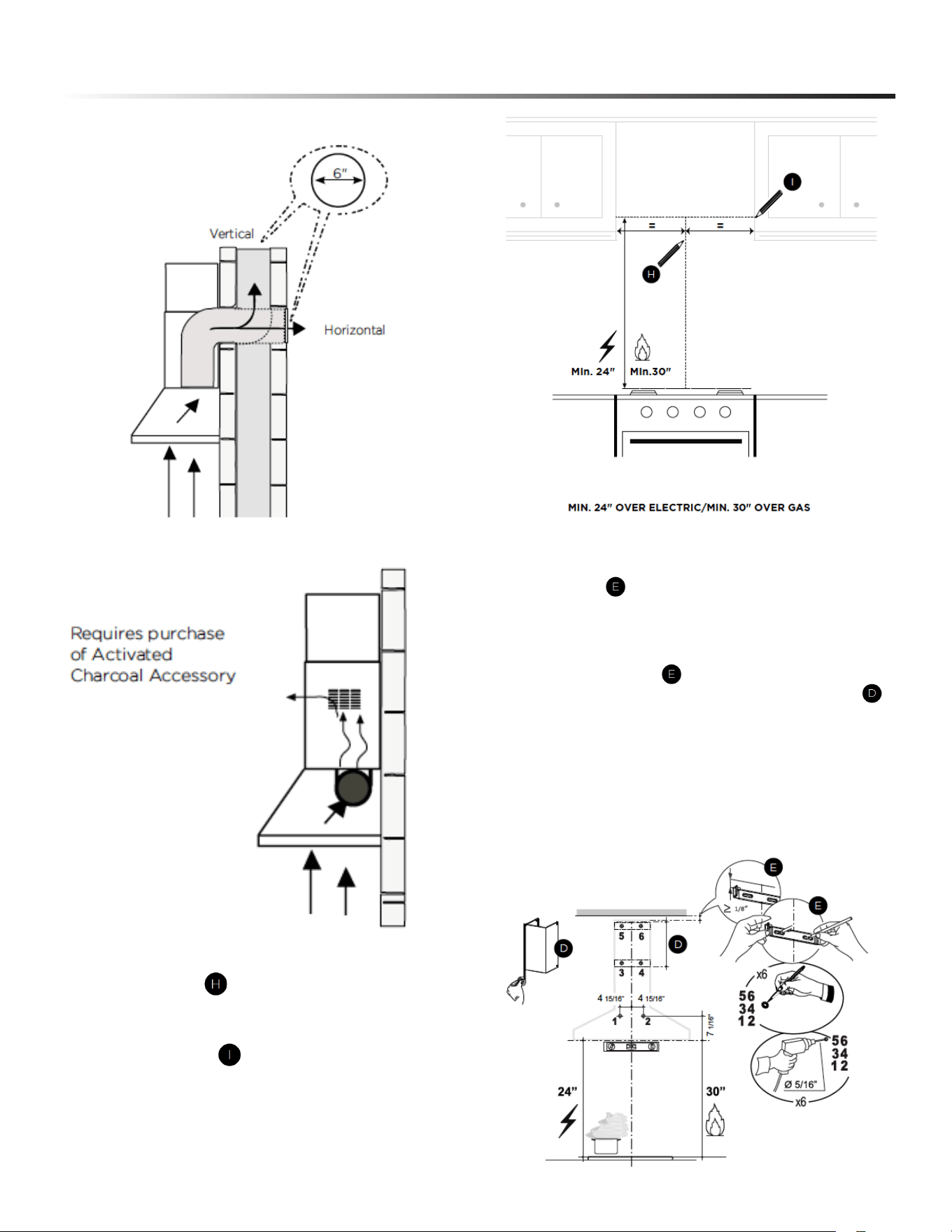
DUCTED WITH 6” ROUND OUTLET:
• Vertical
• Horizontal
NON DUCTED - RECIRCULATION OPTION
MOUNTING RANGE HOOD ON WALL
1 Draw a vertical line from the supporting back wall to the
ceiling or upper limit, at the center of the area in which the hood
will be installed.
Draw a horizontal line from where the bottom edge of the
hood will be located, to a minimum of 24” above an electric
cooking surface and 30” above a gas cooking surface.
2 Draw a horizontal line where indicated at the bottom edge of
the vent hood at the desired height above the cooking surface.
Place a bracket on the wall as shown about 1/8” from the
ceiling or upper limit, aligning the centers (notch) with the
vertical reference line and mark the wall at the centers of the
holes in the bracket.
Place the second bracket on the wall as shown, below
the rst bracket, at the height of the upper chimney section
supplied and aligning the centers (notch) with the vertical line.
Mark the wall at the centers of the holes in the bracket and
mark the point 1 and 2 for the Hood Body installation as shown
(7 1/16” from the horizontal line and 4 15/16” from the vertical
line).
Drill ø 5/16” holes at all the centers points marked (point
1,2,3,4,5,6) as shown.
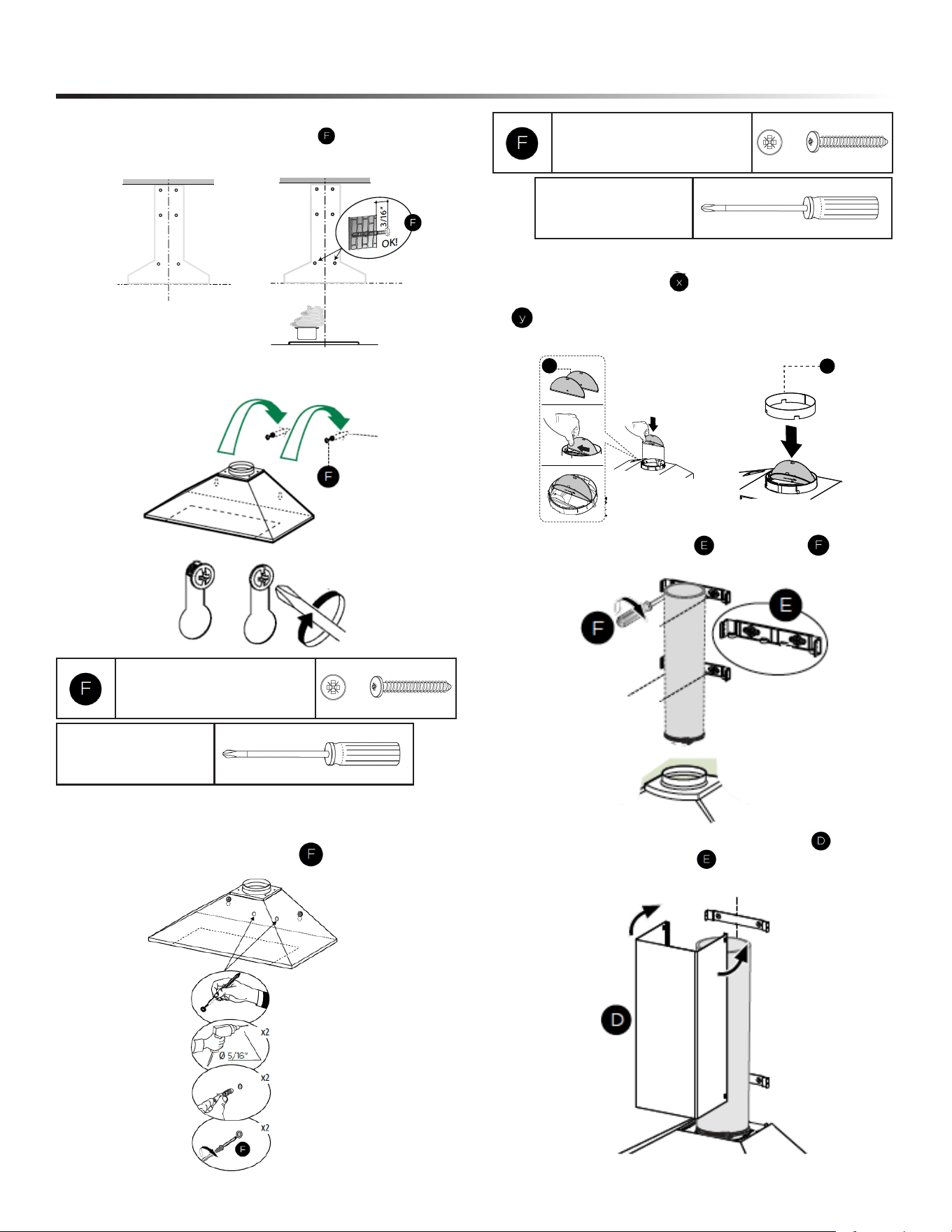
13
INSTALLATION INSTRUCTIONS
3 Install wall plugs if needed (purchase separately).
Partially insert the two screws supplied , into the wall as
shown onto holes 1 and 2.
4 Hang the hood on the wall by pushing the screws through
the 2 designated key holes on the back of the hood. Tighten
the screws.
5 From inside the hood, mark the holes for the two security
holes, drill a 5/16” x 2 where marked. Insert 2 wall plugs into
the holes and tightly screw 2 screws .
Pozi Screwdriver
Pozi Screws (3/16” x 1 15/16”)
Pozi Screwdriver
6 Vertical or Horizontal Ducting Installation
Install the 2 Damper Flaps included with the Range Hood
as shown. Break the 4 pre-cutting pieces and install the Ring
included with the Range Hood before connecting to the
ductwork.
Pozi Screws (3/16” x 1 15/16”)
7 Attach the 2 chimney brackets using 4 screws supplied.
8 Slightly widen the two sides of the upper chimney and
hook them behind the brackets making sure that they are
well seated.
16
Vertical or Horizontal Ducting Installation
Install the 2 Damper Flap
x
included with the Range Hood as shown.
Break the 4 pre-cutting pieces and install the Ring
y
included with the
Range Hood before connecting to the ductwork.
6
I
x
y
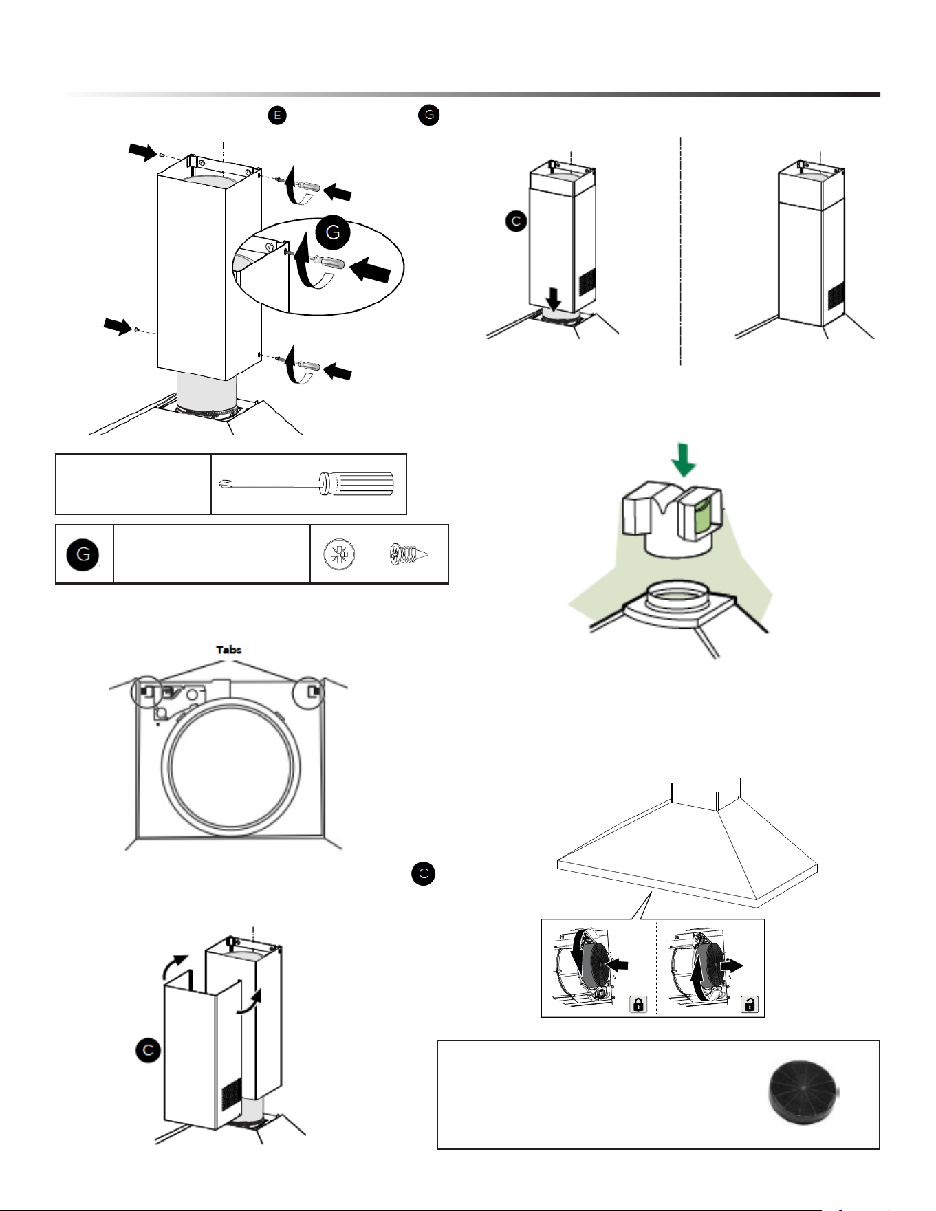
14
INSTALLATION INSTRUCTIONS
9 Secure the sides to the brackets by using the 4 screws .
Pozi Screws (1/8” x 7/16”)
Pozi Screwdriver
10 Using a athead screwdriver, lift up the tabs on the top
of the Canopy.
11 Slightly widen the two sides of the lower chimney hood
and hook them between the upper section and the wall,
making sure that the are properly housed.
12 Install the lower chimney.
13 Non-Ducted Recirculation Option
Only for the recirculation version, connect the ductless
diverter onto the top of the hood body (purchased separately).
Required Activated Charcoal Filter Accessory
- sku # - SKCH63CFL
14 Attach each charcoal lter to the black grid on each side of
the blower. Press the charcoal lter tightly to the black grid on
the blower side and rotate the lter counterclockwise (towards
the front of the hood) until it locks into place. Turn clockwise
(towards the back of the hood) to remove.
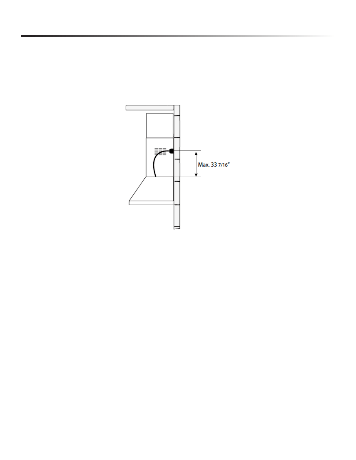
15
INSTALLATION INSTRUCTIONS
15 Electrical Installation With Connection Cable
GROUNDING INSTRUCTIONS This appliance must be grounded. In the event of an electrical short circuit, grounding reduces the
risk of electric shock by providing an escape wire for the electric current. This appliance is equipped with a cord having a grounding
wire with a grounding plug. The plug must be plugged into an outlet that is properly installed and grounded.
WARNING - Improper grounding can result in a risk of electric shock. Consult a qualied electrician if the grounding instructions are
not completely understood, or if doubt exists as to whether the appliance is properly grounded. Do not use an extension cord. If the
power supply cord is too short, have a qualied electrician install an outlet near the appliance.
16
OPERATING THE CONTROLS
Start the Range Hood several minutes before cooking to develop proper airow. Allow the Range Hood to operate for several minutes after
cooking is complete to clear all smoke and odors from the kitchen.
FOR BEST RESULTS
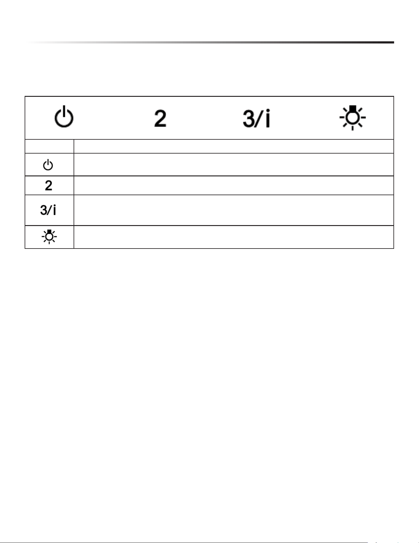
Button Function
Fan Off Button: Turn the blower OFF.
The fan can be operated by pressing any of the fan setting buttons.
Hold down this button for 2 seconds to activate delayed off function which will
keep the fan On for 15 minutes and automatically shut Off.
Fan Setting Button: Low Speed.
Fan Setting Button: Medium Speed.
Fan Setting Button: High Speed.
Hold down the button for 2 seconds to activate the INTENSIVE SPEED, which is
timed to run for 10 minutes. At the end of this time it will automatically return to
the speed set before. Suitable to deal with maximum levels of cooking fumes.
Light Button: ON / OFF for the LED lights. Press the LIGHT button to turn the light ON, again to turn OFF.
NOTE: If your product has had a CFM adjustment, refer to the CFM adjustment manual for the information. Some motor speeds or functions
may be reduced.
APPLICABLE FOR THE FOLLOWING MODELS: SHC3063SNS, SHC3063KNS, & SHC3663SNS
17
OPERATING THE CONTROLS
Start the Range Hood several minutes before cooking to develop proper airow. Allow the Range Hood to operate for several minutes after
cooking is complete to clear all smoke and odors from the kitchen.
FOR BEST RESULTS
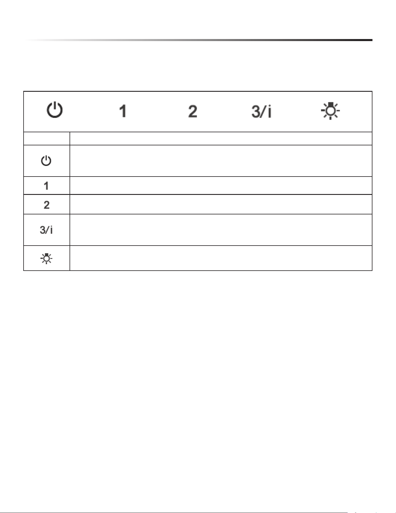
Button Function
Turns the Motor ON at Speed one.
Turn the blower OFF.
Turns the Motor ON at Speed two.
When pressed briey, turns the Motor ON at Speed three.
Pressed for 2 seconds. Activates Speed four with a timer set to 6 minutes, after which it returns to the speed that was set
previously. Suitable to deal with maximum levels of cooking fumes.
Turns the Lighting System ON and OFF.
NOTE: If your product has had a CFM adjustment, refer to the CFM adjustment manual for the information. Some motor speeds or functions
may be reduced.
APPLICABLE FOR THE FOLLOWING MODELS: SHC2443SNS & SHC3043SNS
18
CLEANING & MAINTENANCE
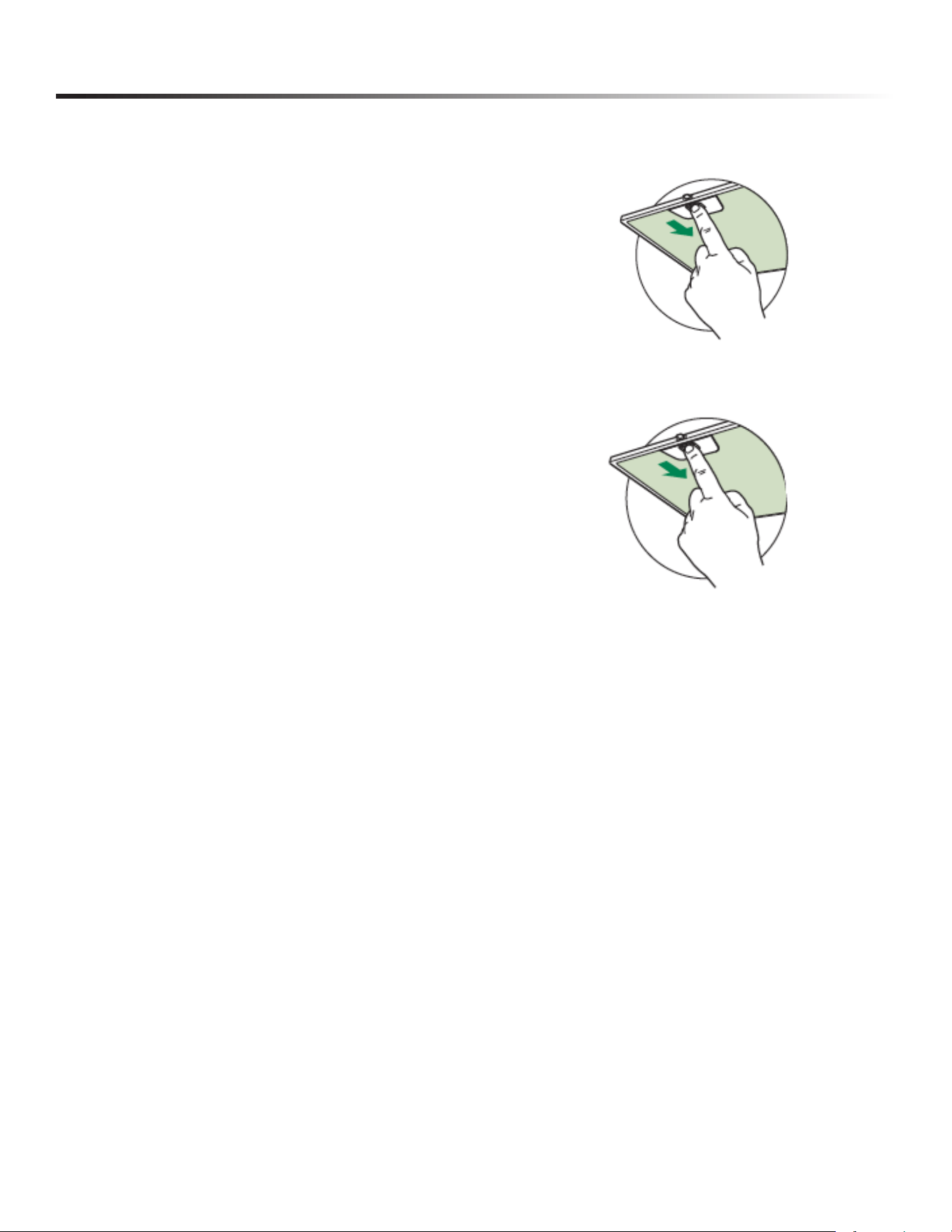
The metal grease lters can be cleaned in hot detergent solution or washed in the dishwasher. They should be cleaned every 2 months use, or
more frequently if use is particularly heavy.
CLEANING METAL GREASE FILTERS
1 Remove the lter, pushing the lever towards the back of the unit while pulling
downward.
2 Wash the lter without bending it. Leave it to dry thoroughly before
replacing. If the surface of the lter changes color over time, efciency will
not be affected.
3 To replace the lter, push the lter up into position while holding the lever
back, then release lever to lock in place.
• Cleaning in a dishwasher may dull the nish of the metal grease lters.
• Ensure that the lters are completely dry before installing them back into the Range Hood.
NOTES:
CLEANING EXTERIOR SURFACES
Please note, abrasives and scouring agents can scratch range hood nishes and should not be used to clean nished surfaces.
Stainless Steel nish cleaning instructions:
Clean exterior surfaces with a commercially available stainless steel cleaner.
19
CLEANING & MAINTENANCE
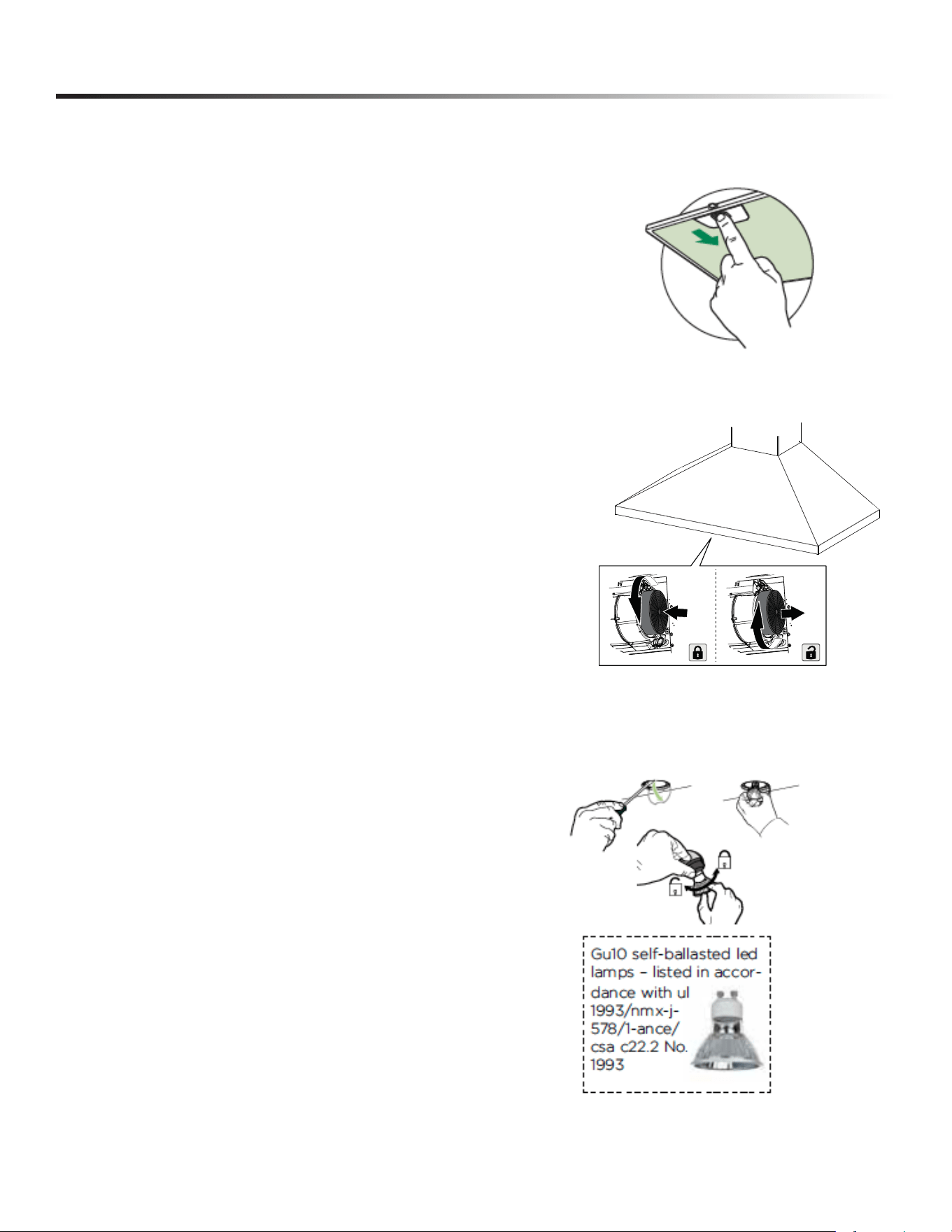
The Activated Charcoal Filters are not washable and cannot be regenerated, and must be replaced approximately every 4 months
of operation, or more frequently with heavy usage.
REPLACING ACTIVATED CHARCOAL FILTER
1 Remove the grease lters.
2 Remove the saturated charcoal lter by rotating it clockwise (backwards) until
it unlocks from the motor housing and pull off sideways.
3 To re-insert each charcoal lter, place up against the side of the blower and
push it inward. Then turn the charcoal lter counterclockwise (forward)
until it ts into place.
• Remove the snap-on lamp cover by levering it from under the metal ring,
supporting it with one hand.
• Replace the lamp with a new one of the same type, making sure that you
insert the two pins properly into the housings on the lamp holder.
• Replace the snap-on lamp cover.
REPLACING LIGHTING

20

21

22

23

24
SHARP ELECTRONICS CORPORATION • 100 Paragon Drive • Montvale, New Jersey 07645 • USA
800-BE-SHARP (800-237-4277)
February 15, 2026