100379659_2000812395
Installa on Instruc ons and
Use & Care Guide
Keep this manual in the pocket on heater for future reference whenever maintenance, adjustment or service is required.
Retain your original receipt as proof of purchase.
LOW LEAD
C
O
NTENT
DO NOT RETURN THIS UNIT TO THE STORE
Read this manual and the labels on the water heater before you install,
operate, or service it. If you have diffi culty following the direc ons, or
aren’t sure you can safely and properly do any of this work yourself:
• Call your Local plumbing supplies store to have this water heater installed.
Professional Installa on is available for this product and the work is guaranteed.
• Schedule an appointment with a qualifi ed person to install your water heater.
• Call our Technical Assistance Hotline at 1-800-527-1953. We can help you with
installa on, opera ons, troubleshoo ng, or maintenance. Before you call, write
down the model and serial number from the water heater’s data plate.
Incorrect installa on, opera on, or service can damage the water heater, your
house and other property, and present risks including fi re, scalding, electric shock,
and explosion, causing serious injury or death.
AHRI Cer fi ca on® applies to residen al electric water heaters with rated
capaci es of 20 to 120 gallon and input ra ngs of 12 kw or less.
Table of Contents ................................... Page
Important Safety Informa on ............................................... 3
Ge ng Started ....................................................................... 6
Installa on .............................................................................. 7
Opera on ............................................................................. 19
Troubleshoo ng ................................................................... 25
Maintenance ........................................................................ 32
Diagrams............................................................................... 38
Repair Parts .......................................................................... 39
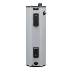
Hybrid Electric
Heat Pump Water Heater
March 2025
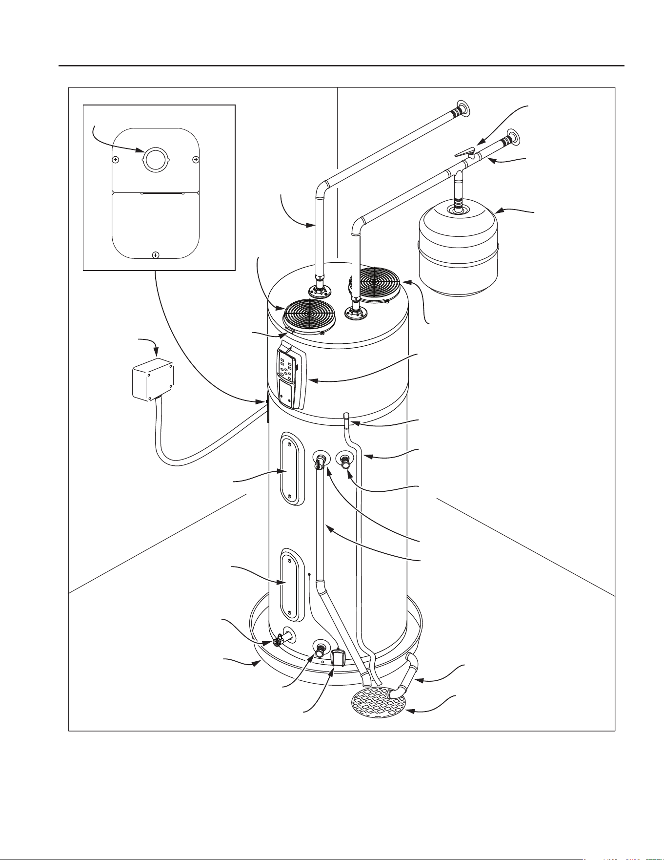
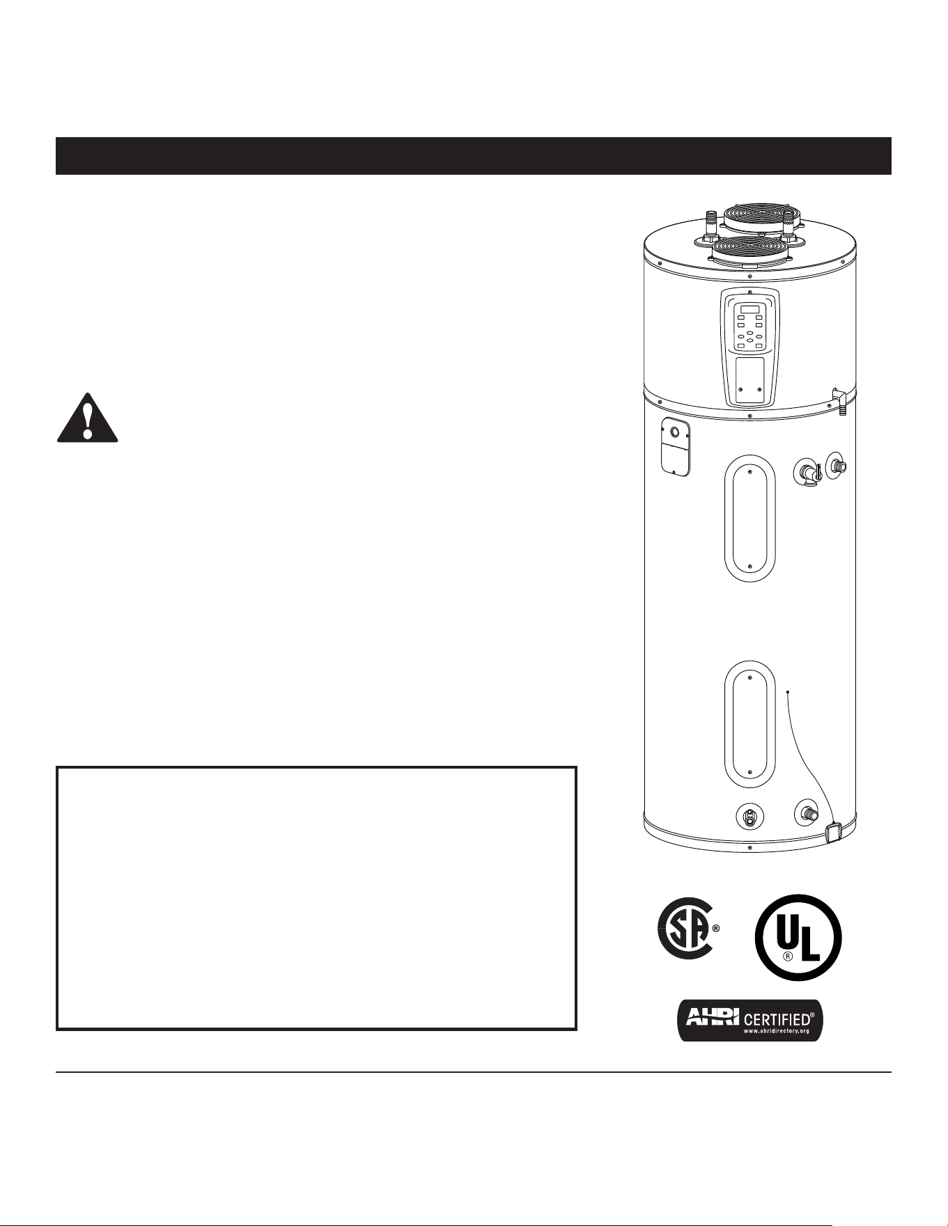
COMPLETED INSTALLATION TYPICAL
2 • Residen al Electric Water Heater Use and Care Guide
Water shut-o
valve
Cold water line
Thermal
expansion tank
Drain pan discharge pipe
Drain
Leak detection sensor
Drain valve
Drain pan
Lower element
Upper element
and ECO
Electrical
junction
box
Hot water line
Condensate line (supplied)
Condensate drain
Control panel
T&P discharge pipe
(Do not cap or plug)
T&P relief valve
Intake air
Exhaust air
Optional side outlet (capped)
Optional side inlet (capped)
Intake lter
1/2” (13mm) Conduit Opening
Notes:
1) If copper piping is used, then unions must be dielectric at inlet and outlet.
2) Plumb piping to desired inlet and outlet, either top or side (not in combination), and cap unused inlet and outlet to avoid
water leaks.
Residen al Electric Water Heater Use and Care Guide • 3
IMPORTANT SAFETY INFORMATION
SAFETY
Important informa on to keep
Fill out this sec on and keep this
manual in the pocket of the water heat-
er for reference.
Date Purchased:
Model number:
Serial number:
Maintenance performed:* Date:
*Drain and fl ush tank, clean air fi lter,
clean condensate pan, and remove and
inspect anode rod a er fi rst six months
of opera on and at least annually
therea er. Inspect and operate the
Temperature and Pressure Relief Valve
(T&P) annually (see the label on the
T&P valve for maintenance schedule).
If no label is a ached to the T&P Relief
Valve, follow the instruc ons in the T&P
Relief Valve Maintenance sec on of this
manual.
See the Maintenance sec on for
more informa on about maintaining this
water heater.
This product is certified to comply with a maximum weighted average of
0.25% lead content as required in some areas.
This is the safety alert symbol. It is used to alert you to
poten al physical injury hazards. Obey all safety messages
that follow this symbol to avoid possible property damage,
serious injury or death. Do not remove any permanent
instruc ons, labels, or the data plate from either the
outside of the water heater or on the inside of the access panels. Keep this
manual near the water heater.
DANGER
DANGER indicates hazardous
situa on that, if not avoided, will
result in death or serious injury.
WARNING
WARNING indicates a hazardous
situa on that, if not avoided, could
result in death or serious injury.
CAUTION
CAUTION indicates a hazardous
situa on that, if not avoided, could
result in minor or moderate injury.
NOTICE
NOTICE indicates prac ces not relat-
ed to physical injury.
Read and follow all safety messages and instruc ons in this
manual.
4 • Residen al Electric Water Heater Use and Care Guide
To reduce the risk of property
damage, serious injury or death, read
and follow the precau ons below,
all labels on the water heater, and
the safety messages and instruc ons
throughout this manual.
RISKS DURING
INSTALLATION AND
MAINTENANCE
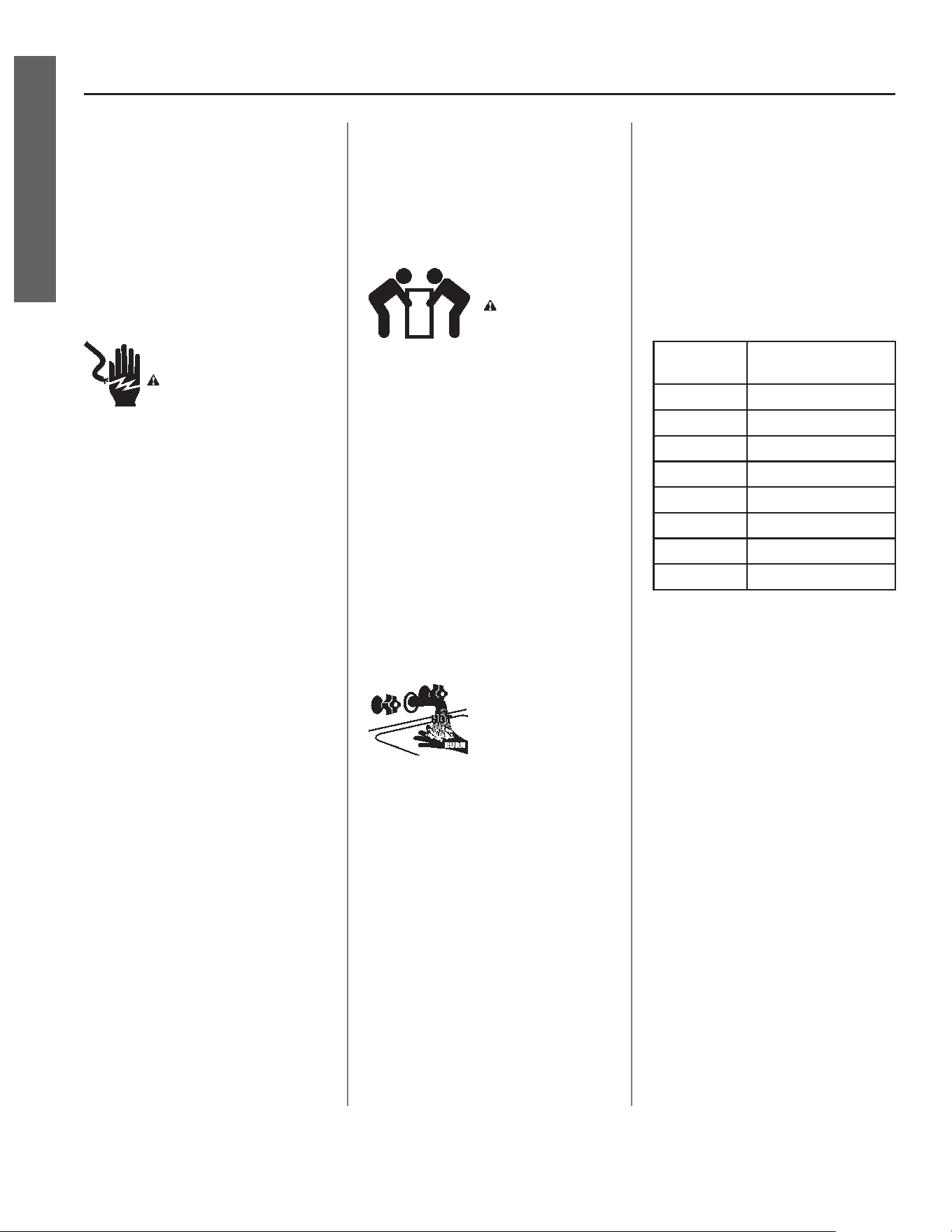
Electric Shock Risk
WARNING! Contact
with the electrical parts in
the junc on box, behind
the access doors and inside the top
shroud can result in severe injury
or death from the electrical shock.
Safety and precau ons to reduce
the risk of fi re, electric shock or
injury to persons should be followed,
including:
• READ ALL INSTRUCTIONS BEFORE
USING THE WATER HEATER.
• This water heater must be ground-
ed. See the “Electrical Connec ons”
sec on found in the “Installa on”
chapter of this manual.
• Install or locate this water heater
only in accordance with the provid-
ed manual.
• Use this water heater only for its
intended use as described in this
manual.
• As with any appliance, close super-
vision is necessary when used by
children.
• This water heater should be serviced
only by qualifi ed personnel. Contact
a service person for examina on,
repair or adjustment.
• Disconnect power by opening the
circuit breaker or removing the fus-
es before installing or servicing.
• Use a non-contact circuit tester to
confi rm that power is OFF before
working on or near any electrical
parts.
• Replace all parts and panels before
opera ng.
Li ing Risk
WARNING! The
water heater is
heavy. Follow these
precau ons to reduce the risk of
property damage, injuries from li ing
or impact injuries from dropping the
water heater.
• Use at least two people to li the
water heater.
• Be sure you both have a good grip
before li ing.
• Unit is top heavy, use an appliance
dolly (with strap) to move the water
heater.
RISKS DURING
OPERATION
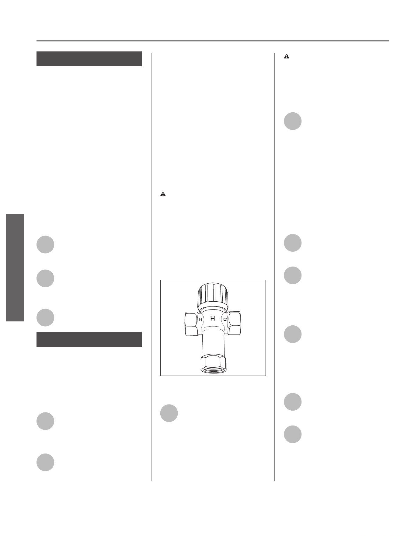
Scalding Risk
This water heater
can make water hot
enough to cause
severe burns instantly, resul ng in
severe injury or death.
• Feel water before bathing or show-
ering.
• To reduce the risk of scalding, install
Thermosta c Mixing Valves (tem-
perature limi ng valves) at each
point-of-use. These valves automa -
cally mix hot and cold water to limit
the temperature at the tap. Mixing
valves are available from your local
plumbing supplier. Follow manufac-
turer’s instruc ons for installa on
and adjustment of the valves.
• The Control Assembly on this water
heater has been factory set to
approximately 120°F/49°C to reduce
the risk of scalding. Higher tempera-
tures increase the risk of scalding,
but even at 120°F/49°C, hot water
can scald. If you choose a higher
temperature, Thermosta c Mixing
Valves located at each point-of-use
are par cularly important to help
avoid scalding.
Temperature Time to Produce a
Serious Burn
120°F (49°C) More than 5 minutes
125°F (52°C) 1½ to 2 minutes
130°F (54°C) About 30 seconds
135°F (57°C) About 10 seconds
140°F (60°C) Less than 5 seconds
145°F (63°C) Less than 3 seconds
150°F (66°C) About 1½ seconds
155°F (68°C) About 1 second
For more informa on about changing
the factory thermostat se ng(s), refer
to the “Adjus ng the Temperature”
sec on in this manual (see page 18).
Regardless of the water heater
Control Assembly se ng, higher
temperatures may occur in certain
circumstances:
• In some cases, repeated small draws
of water can cause the hot and cold
water in the tank to “stack” in layers.
If this happens, the water can be as
much as 30°F/15°C degrees ho er
than the thermostat se ng. This
temperature varia on is the result
of your usage pa ern and is not a
malfunc on.
• Water temperature will be ho er if
someone adjusted the thermostat(s)
to a higher se ng.
• Problems with the thermostat(s),
or other malfunc ons may result in
higher than expected water tem-
peratures.
SAFETY
IMPORTANT SAFETY INFORMATION
Residen al Electric Water Heater Use and Care Guide • 5
IMPORTANT SAFETY INFORMATION
SAFETY
• If the water heater is in a hot envi-
ronment, the water in the tank can
become as hot as the surrounding
air, regardless of the thermostat
se ng.
• If the water supplied to the water
heater is pre-heated (for example,
by a solar water hea ng system)
the temperature in the tank may be
higher than the water heater’s ther-
mostat se ng.
To reduce the risk of unusually hot
water reaching the fi xtures in the
house, install Thermosta c Mixing
Valves at each point-of-use.
If anyone in your home is at par cular
risk of scalding (for example, the
elderly, children, or people with
disabili es) or if there is a local code
or state law requiring a certain water
temperature at the hot water tap,
then these precau ons are par cularly
important.
According to the na onal standard
American Society of Sanitary
Engineering (ASSE 1070) and most
local plumbing codes, the water
heater’s thermostat should not be
used as the sole means to regulate
water temperature to avoid scalds.
Properly adjusted Thermosta c Mixing
Valves installed at each point-of-use
allow you to set the tank temperature
to a higher se ng without increasing
risk of scalds. A higher temperature
se ng allows the tank to provide
much more hot water and can help
provide proper water temperatures
for appliances such as dishwashers
and washing machines. Higher tank
temperatures (140°F/60°C) also kill
bacteria that cause a condi on known
as “smelly water” and can reduce the
levels of bacteria that cause water-
borne diseases.
Water Contamina on Risk
Do not use chemicals that could
contaminate the potable water supply.
Do not use piping that has been
treated with chromates, boiler seal, or
other chemicals.
Fire Risk
To reduce the risk of a
fi re that could destroy
your home and seriously injure or kill
people:
• Do not store things that can burn
easily such as paper or clothes next
to the water heater.
• Be sure the junc on box cover and
the element access door covers are
in place. These covers keep debris
from entering and poten ally being
ignited, and help keep any internal
fi res from spreading.
• Keep the water heater from becom-
ing wet. Immediately shut the water
heater off and have it inspected by a
qualifi ed person if you fi nd that the
wiring, thermostat(s) or surrounding
insula on have been exposed to
water in any way (e.g., leaks from
plumbing or leaks from the water
heater itself can damage property
and could cause a fi re risk). If the
water heater is subjected to fl ood
condi ons or the thermostat(s) have
been submerged in water, the en re
water heater must be replaced.
• Make electrical connec ons proper-
ly, according to the instruc ons on
page 17. Use 10 gauge solid copper
wire. Use a UL listed or CSA approved
strain relief. Connect the ground wire
to the green ground screw.
Explosion Risk
High temperatures and
pressures in the water
heater tank can cause an explosion
resul ng in property damage, serious
injury or death. A new Temperature
and Pressure (T&P) Relief Valve is
included with your water heater
to reduce the risk of explosion by
discharging hot water. Addi onal
temperature and pressure protec ve
equipment may be required by local
codes.
A na onally recognized tes ng
laboratory maintains periodic
inspec on of the valve produc on
process and cer fi es that it meets the
requirements for Relief Valves for Hot
Water Supply Systems, ANSI Z21.22.
The T&P Relief Valve’s relief pressure
must not exceed the working pressure
ra ng of the water heater as stated on
the ra ng plate.
Maintain the T&P Relief Valve properly.
Follow the maintenance instruc ons
provided by the manufacturer of the
T&P Relief Valve (label a ached to T&P
Relief Valve). If no label is a ached
to the T&P Relief Valve, follow the
instruc ons in the T&P Relief Valve
Maintenance sec on of this manual.
An explosion could occur if the T&P
Relief Valve or discharge pipe is
blocked. Do not cap or plug the T&P
Relief Valve or discharge pipe.
Fire and Explosion Risk if Hot Water is
Not Used for Two Weeks or More.
CAUTION! Hydrogen gas builds up
in a hot water system when it is not
used for a long period (two weeks
or more). Hydrogen gas is extremely
fl ammable. If the hot water system
has not been used for two weeks or
more, open a hot water faucet for
several minutes at the kitchen sink
before using any electrical appliances
connected to the hot water system.
Do not smoke or have an open fl ame
or other igni on source near the
faucet while it is open.
6 • Residen al Electric Water Heater Use and Care Guide
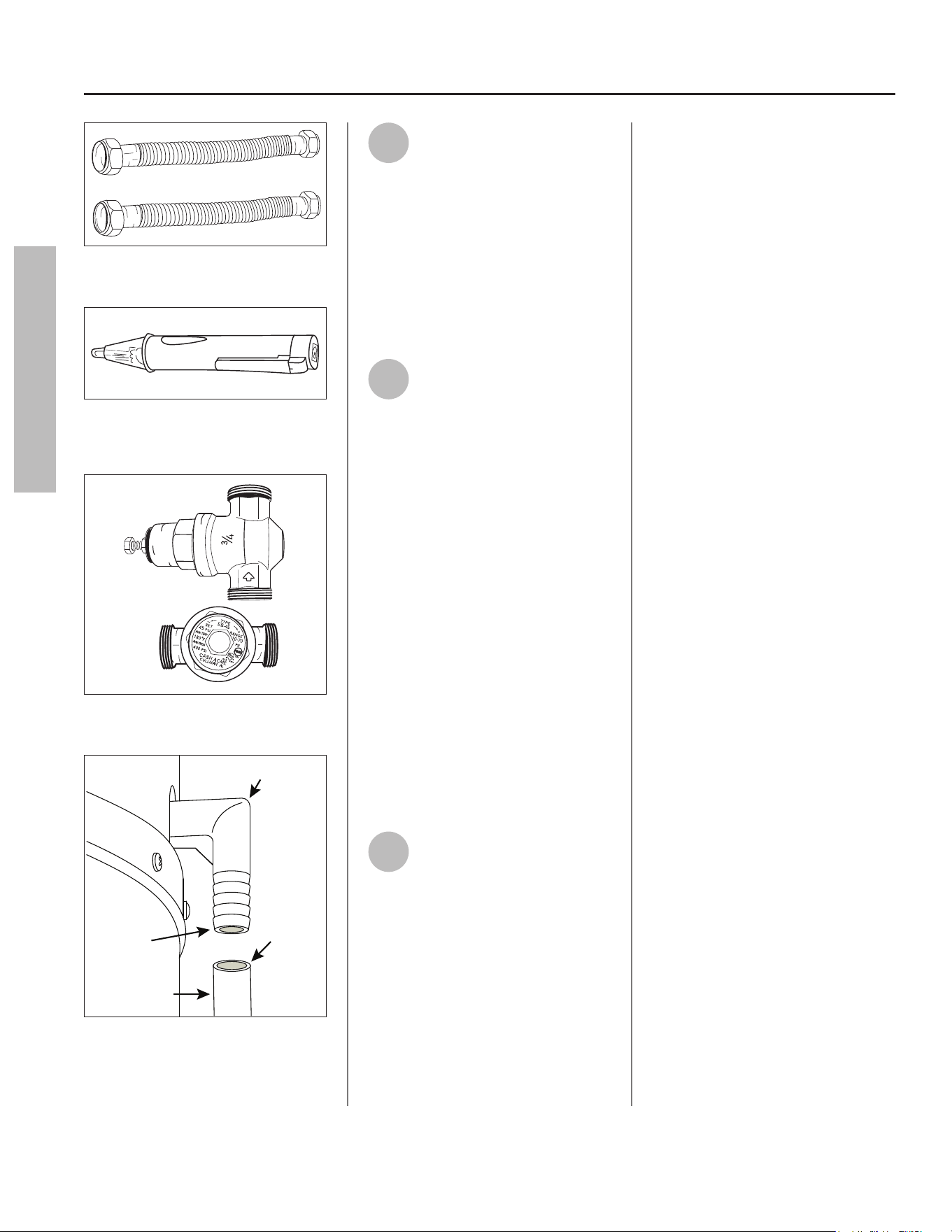
Figure 1 - Flexible connectors use compression
fittings and do not require soldering.
ON
OFF
Figure 2 - Use a non-contact circuit tester to
ensure that the power is off before you work
on a circuit.
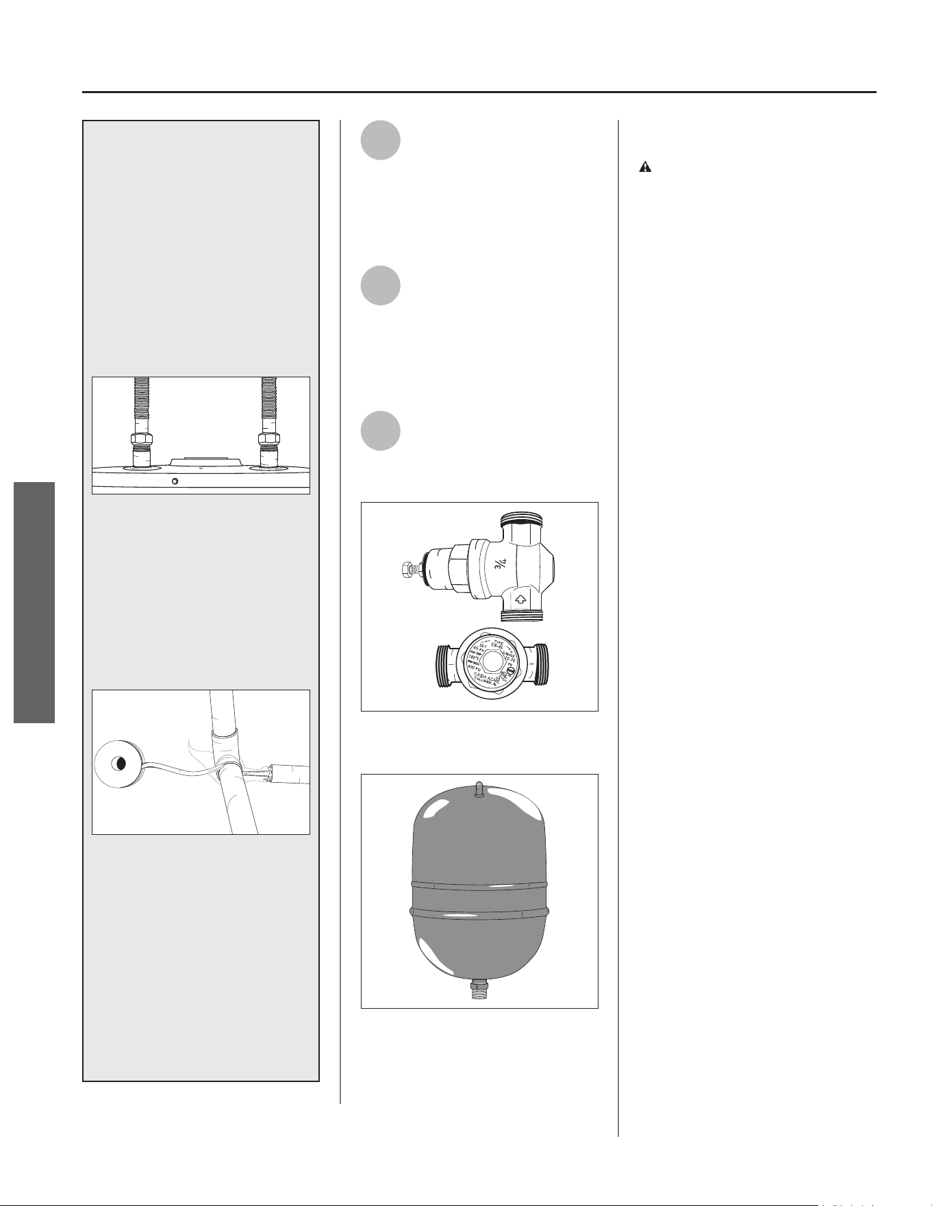
Figure 3 - Install a Pressure Reducing Valve if
required.
Flexible Tubing
Condensate Drain
Ø 5/8” ID
Barbs For
Ø 5/8” ID
Plastic Hose
Figure 4 - Condensate drain connection
1
Review all of the instruc ons
before you begin work. If you
aren’t sure that you can
safely and properly do this work
yourself, call a qualifi ed person of
your choice, such as a licensed
plumber or electrician, to have the
work done. Improper installa on can
damage the water heater, your home
and other property, and can present
risks of serious injury or death.
2
Check with your local and
state authori es for any local
or state codes that apply to
your area. In the absence of local and
state codes, follow Na onal Fire
Protec on Associa on (NFPA-70) and
the current edi ons of the Na onal
Electric Code (NEC) and the
Interna onal Plumbing Code (IPC).
The instruc ons in this manual comply
with na onal codes, but the installer
is responsible for complying with local
codes.
Massachuse s code requires this
water heater to be installed in
accordance with Massachuse s
248-CMR 2.00 and 248-CMR 5.00:
State Plumbing Code. Other local
and state authori es may have
similar requirements or other codes
applicable to the installa on of this
water heater.
3
Before you start, be sure you
have, and know how to use,
the following tools and
supplies:
• Plumbing tools and supplies
appropriate for the type of water
pipes in your home
• Threaded connec ons (Figure 1) for
the cold and hot water pipes
• For homes plumbed with plas c
pipe, use threaded connectors
suitable for the specifi c type of
plas c pipe used: CPVC and PEX
(cross-linked polyethylene). Do not
use PVC pipe
• For homes with copper pipes,
you may purchase connector kits
with compression fi ngs that
don’t require soldering (Figure 1).
Compression fi ngs are easier to
install than soldering copper pipes
• Thread sealant tape or pipe joint
compound approved for potable
water
• Tools to make electrical connec ons
(for example, screwdrivers and wire
strippers)
• Non-Contact circuit tester to check
for power (Figure 2)
• Water Pressure Gauge (Figure 5 on
page 7)
• Safety Gloves
Recommended Accessories:
• Suitable drain pan (Figure 7 on page
8)
• Shut-off device (kit available)
• Pressure Reducing Valve (Figure 3)
• Thermal Expansion Tank (Figure 6 on
page 7)
• Point-of-use Thermosta c Mixing
Valves (Figure 8 on page 8)
GETTING STARTED
GETTING STARTED
Residen al Electric Water Heater Use and Care Guide • 7
INSTALLATION
INSTALLATION
IMPORTANT: Follow these steps for
proper installa on.
Step 1:
ᅚ
Verify that Your
Home is Equipped
and Up-to-Date
for Proper Installa on
Installing a new water heater is the
perfect me to examine your home’s
plumbing system and make sure the
system is up to current code standards.
There have likely been plumbing
code changes since the old water
heater was installed. We recommend
installing the following accessories
and make any other changes to bring
your home up to the latest code
requirements.
Use this checklist and inspect your
home. Install any devices you need
to comply with codes and assure that
your new water heater performs at its
best. Check with your local plumbing
offi cial for more informa on.
ᅚ
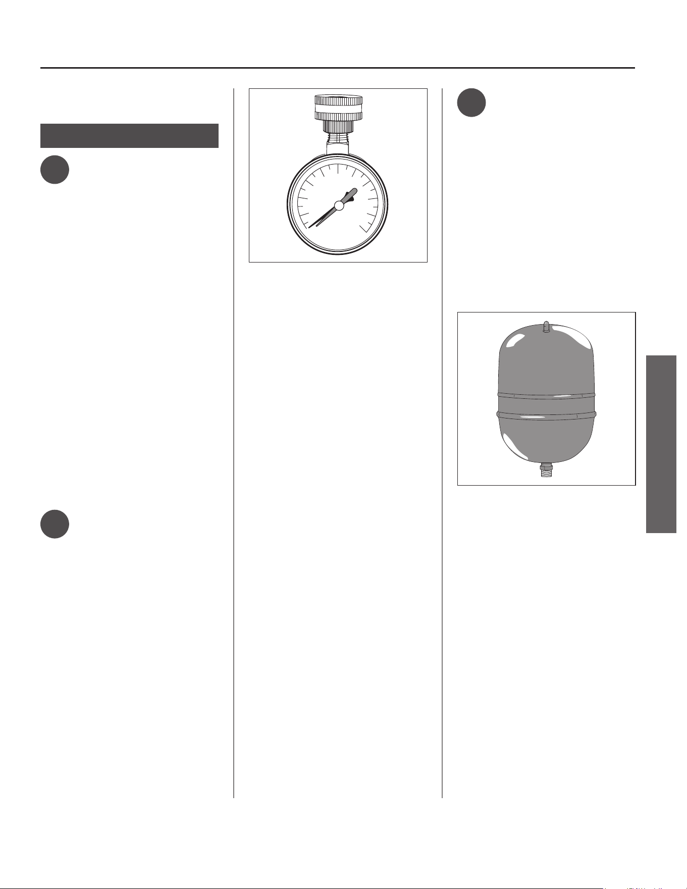
Water Pressure
We recommend checking your
home’s water pressure with a pressure
gauge (Figure 5). Most codes allow a
maximum incoming water pressure
of 80 psi/551 kpa. We recommend a
working pressure no higher than
50-60 psi/345-414 kpa.
HOW: Purchase an inexpensive water
pressure gauge available at your local
plumbing supplier. Connect the Water
Pressure Gauge to an outside faucet
and measure the maximum water
pressure experienced throughout the
day (highest water pressures o en
occur at night).
140
20
40
60
80
100
120
160
180
200
psi
AVOID FREEZING
Figure 5 - Use a Water Pressure Gauge to make
sure your home’s water pressure is not too high.
To limit your home’s water pressure:
Locate your home’s Pressure Reducing
Valve (PRV) on the main incoming
(cold) water supply line and adjust the
water pressure control between 50
and 60 psi. If your home does not have
a Pressure Reducing Valve, install a
PRV on the home’s main water supply
line and set it to between 50 and
60 psi. Pressure Reducing Valves
are available at your local plumbing
supplier.
BACKGROUND: Over the years,
many u li es have increased water
supply pressures so they can serve
more homes. In some homes today,
pressures exceed 100 psi/689 kpa.
High water pressures can damage
water heaters, causing premature
leaks. If you have replaced toilet
valves, had a water heater leak, or
had to repair appliances connected to
the plumbing system, pay par cular
a en on to your home’s water
pressure. When purchasing a PRV,
make sure the PRV has a built-in
bypass.
ᅚ
Water Pressure
Increase Caused
by Thermal
Expansion
Verify that you have a properly sized
Thermal Expansion Tank (Figure 6). We
recommend installing an expansion
tank if your home does not have one.
Codes require a properly pressurized,
properly sized Thermal Expansion
Tank in all homes that have backfl ow,
check or pressure reducing valves (see
illustra on on inside front cover).
Figure 6 - A Thermal Expansion Tank helps
protect the home’s plumbing system from
pressure spikes.
HOW: Connect the Thermal Expansion
Tank (available at your local plumbing
supplier) to the cold water supply
line near the water heater. The
expansion tank contains a bladder
and an air charge. To work properly,
the Thermal Expansion Tank must be
sized according to the water heater’s
tank capacity and pressurized to match
the home’s incoming water pressure.
Refer to the installa on instruc ons
provided with the Thermal Expansion
Tank for installa on details.
BACKGROUND: Water expands when
heated, and the increased volume
of water must have a place to go, or
thermal expansion will cause large
8 • Residen al Electric Water Heater Use and Care Guide
increases in water pressure (despite
the use of a Pressure Reducing
Valve on the home’s main water
supply line). The Safe Drinking Act
of 1974 requires the use of backfl ow
preventers and check valves to restrict
water from your home reentering
the public water system. Backfl ow
preventers are o en installed in
water meters and may not be readily
visible. As a result, most all plumbing
systems today are now “closed,” and
almost all homes now need a Thermal
Expansion Tank.
A Thermal Expansion Tank is a
prac cal and inexpensive way to help
avoid damage to the water heater,
washing machine, dishwasher, ice
maker and even toilet valves. If
your toilet occasionally runs for no
apparent reason (usually briefl y at
night), that may be due to thermal
expansion increasing the water
pressure temporarily.
ᅚ
Water Pipe and
Tank Leaks
Leaks from plumbing pipes or from
the water heater itself can damage
property and could cause a fi re risk.
• Install the provided leak detec on
sensor (see “Step 15” on page 18).
An automa c cold water shut-off
valve is also available for purchase
(kit p/n 100345338). If an automa c
cold water shut-off valve has been
purchased, see “Step 9” on page 13
for installa on instruc ons. These
devices can detect water leaks and
can shut off the water heater’s
water supply if a leak occurs.
• Install a suitable drain pan (available
at your local plumbing supplier)
under the water heater (Figure 7) to
catch condensa on or leaks in the
piping connec ons or tank. Most
codes require, and we recommend,
installing the water heater in a drain
pan that is piped to an adequate
drain. The drain pan must be at least
2” (50 mm) wider than the diameter
of the water heater. Install the
drain pan so the water level would
be limited to a maximum depth of
1-3/4” (45 mm).
Drain
Drain Pan
Leak Detection Sensor
Drain Pan
Discharge Pipe
Figure 7 - A suitable drain pan piped to an
adequate drain can help protect flooring from
leaks and drips.
ᅚ
Water Tempera-
ture Regula on
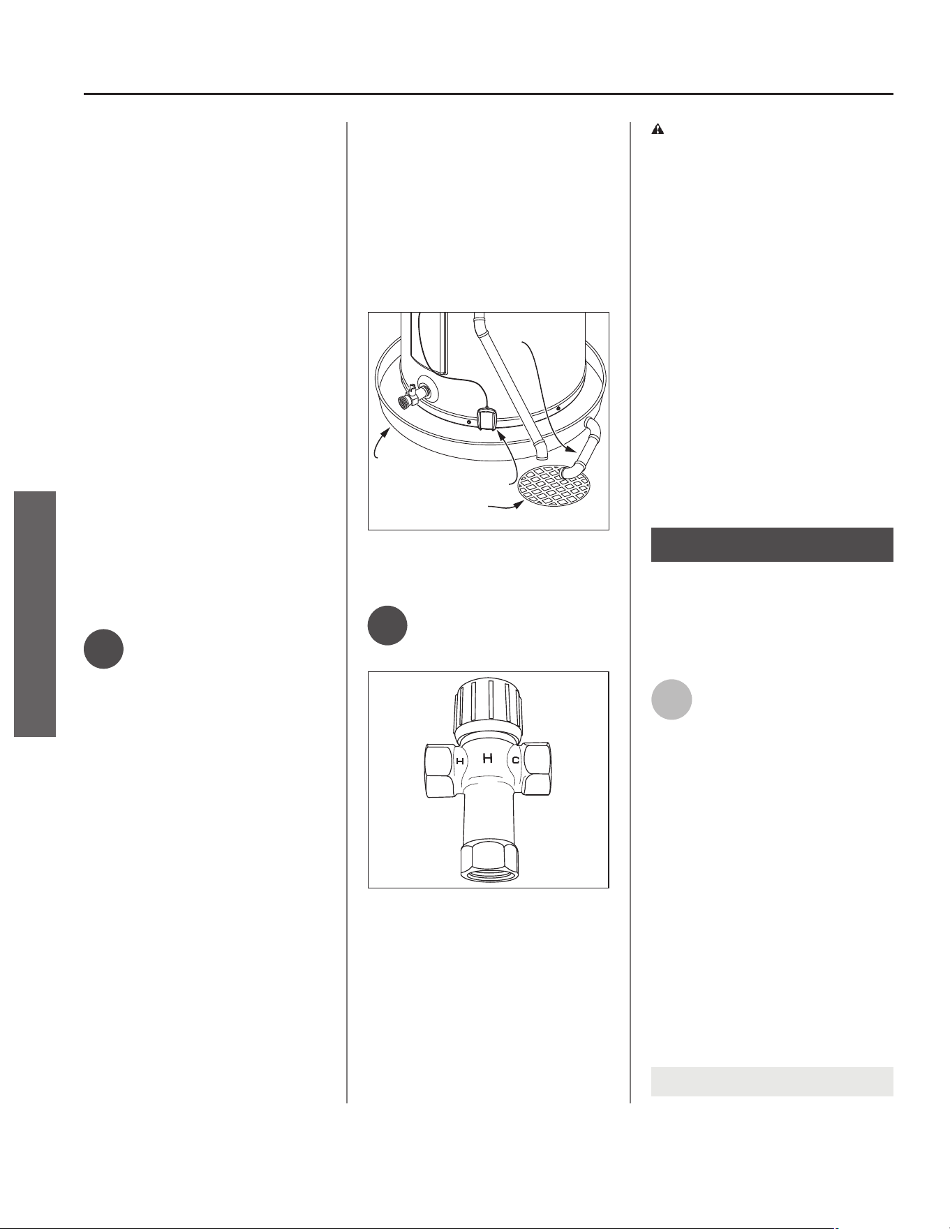
MIX
Figure 8 - Thermostatic Mixing Valves installed
at each point-of-use can help prevent scalds.
Install Thermosta c Mixing Valves
(Figure 8) to regulate the temperature
of the water supplied to each point-
of-use (for example, the kitchen sink,
bathroom sink, bath and shower).
Consult the valve manufacturer’s
instruc ons or a qualifi ed person.
WARNING! Even if the water
heater thermostat is set to a
rela vely low temperature, hot water
can scald. Install Thermosta c Mixing
Valves at each point-of-use to reduce
the risk of scalding (see page 4 and
Figure 8).
BACKGROUND: A Thermosta c Mixing
Valve, installed at each point-of-use,
mixes hot water from the water
heater with cold water to more
precisely regulate the temperature of
hot water supplied to fi xtures. If you
are not sure if your plumbing system
is equipped with properly installed
and adjusted Thermosta c Mixing
Valves, at each point of use where
hot water is used, contact a qualifi ed
person for more informa on.
Step 2:
Verify that the Loca on
is Appropriate
Before installing your water heater,
ensure that:
1
The water heater will be:
• Installed indoors close to the center
of the plumbing system.
• In a suitable drain pan piped to an
adequate fl oor drain or external to
the building (Figure 7).
• In an area that will not freeze.
• In an area that is suitable for
installing the water heater ver cally
and on a level surface.
• Installed where a typical home
appliance sound would not cause a
disturbance.
• Not used for space hea ng.
NOTICE: Water heater must be level!
INSTALLATION
INSTALLATION
Residen al Electric Water Heater Use and Care Guide • 9
INSTALLATION
INSTALLATION
2
The loca on has adequate
space (clearances) for periodic
servicing. For op mal water
heater effi ciency in unvented
applica ons, the unit must have
unrestricted airfl ow and requires a
minimum installa on space of 450 ³
(12.7 m³). As an example, a room that
has an 8 (2.4 m) tall ceiling and is
7-3/4 (2.3 m) long by 7-1/4 (2.2 m)
wide would contain 450 ³ (12.7 m³).
NOTICE: This Heat Pump Water Heater
may be located within a required
minimum of 6”/152 mm clearance
from the front side and 12”/305 mm
clearance from the top of the water
heater. However, for future service
considera ons, a minimum of 3 /.9 m
from any obstruc on on the front side
is recommended.
3
The fl oor can support the
weight of a full water heater.
Capacity Filled Weight (lbs.)
50 Gallon 573
66 Gallon 796
80 Gallon 921
4
Your area is not prone to
earthquakes. If it is, use
special straps as required by
local building codes.
NOTICE: The state of California
requires bracing, anchoring or
strapping the water heater to avoid
its moving during an earthquake.
To contact local u li es for code
requirements in your area, visit
h p://www.dsa.dgs.ca.gov, or call
1-916-445-8100 and request
instruc ons. Other loca ons may have
similar requirements. Check with your
local and state authori es.
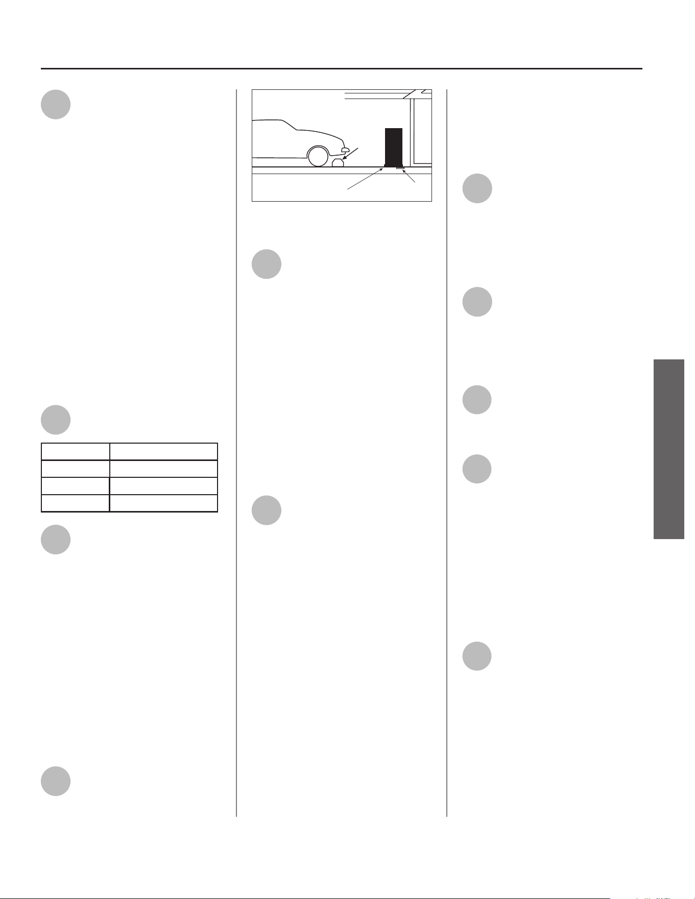
5
The loca on is not prone to
physical damage by vehicles,
fl ooding, or other risks.
Vehicle
Stop
Drain
Drain
Pan
Figure 9 - In a garage, install a vehicle stop to
avoid water heater damage.
6
Avoid loca ons such as a cs,
upper fl oors, or where a leak
might damage the structure
or furnishings. Due to the normal
corrosive ac on of water, the tank will
eventually leak. To minimize property
damage from leaks, inspect and
maintain your water heater in
accordance with this manual’s
instruc ons. Inspect the drain pan,
pipes, and surrounding area regularly
and fi x any leaks found. Drain pans are
available at your local plumbing
supplier. Leaks are frequently in the
plumbing system itself and not the
water heater.
7
The unit cannot be placed into
any type of closet or small
enclosure (less than 450 ³),
unless adequate provisions are made
for air exchange (vented or louvered
doors, wall grilles, duc ng, etc.). Wall
grilles shall be a minimum size of 22
inches by 6 inches, or provide the
equivalent area of airfl ow (a minimum
net free area of 130 in²).
For small enclosures with a minimum
installa on space of 84 ³ to 449 ³
(2.3 m³ to 12.7 m³), the following
methods of ven la on are acceptable:
• A fully louvered door.
• One wall grille located a minimum
of 12 inches from the ceiling, and a
second wall grille located a minimum
of 12 inches from the fl oor.
• One wall grille located a minimum
of 12 inches from the ceiling, and
an undercut door providing 3/4” of
clearance (or a minimum net free
area of 18 in²).
8
To ensure op mal
performance and
serviceability, a minimum
clearance of 6”/152 mm must be
maintained from the front side and
12”/305 mm from the top for access
and serviceability.
9
Water heaters located in
uncondi oned spaces (i.e.,
garages, basements, etc.) may
require the water piping, condensate
piping, and drain piping to be insulated
to guard from freezing.
10
The air fi lter, condensa on
drain and controls must be
easily accessible for opera on
and service.
11
The site loca on must be free
from any corrosive elements
in the atmosphere such as
sulfur, fl uorine, sodium and chlorine.
These elements are found in aerosol
sprays, detergents, bleaches, air
fresheners, paint and varnish
removers, refrigerants and many other
household products. In addi on,
excessive dust and lint may aff ect the
opera on of the unit (see “Air Filter
Maintenance” on page 37).
12
The ambient air temperature
must also be considered when
installing this unit. In Heat
Pump Mode, the air temperature
needs to be above 37°F/3°C and below
120°F/49°C for heat pump operation. If
the air temperature falls outside these
upper and lower limits, the electrical
elements will activate to meet the hot
water demand. In this scenario, the
heat pump will not operate in either
Heat Pump Mode or Hybrid Mode.
10 • Residen al Electric Water Heater Use and Care Guide
Step 3:
Removing the Old
Water Heater
1
Read each installa on step
and decide if you have the
necessary skills to install the
water heater. Only proceed if you can
safely perform the work. If you are
not comfortable, have a qualifi ed
person perform the installa on.
2
Locate the water heater’s
circuit breaker and turn it
OFF (or remove the circuit’s
fuses).
3
On the old water heater,
remove the electrical
junc on box access panel.
Using a non-contact circuit tester,
check the wiring to make certain the
power is OFF.
WARNING! Working on an
energized circuit can result in severe
injury or death from electrical shock.
4
Disconnect the electrical
wires.
5
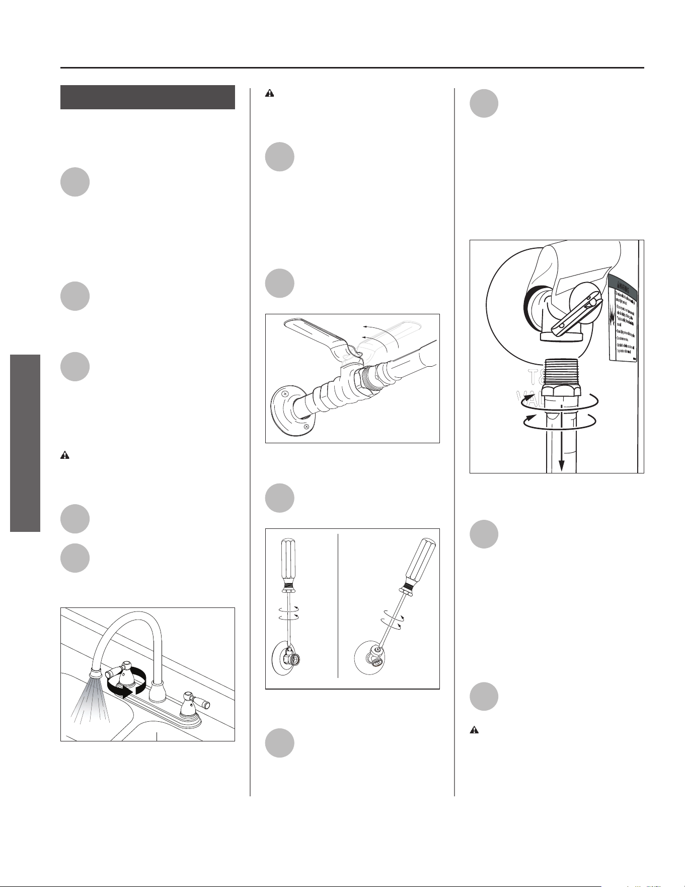
Open a hot water faucet and
let the hot water run un l it
is cool (this may take 10
minutes or longer).
Figure 10 - Let the hot water run until it is cool.
WARNING! Be sure the water
runs cool before draining the tank to
reduce the risk of scalding.
6
Connect a garden hose to the
drain valve and place the
other end of the hose in a
drain, outside, or a bucket. (Note that
sediment in the bo om of the tank
may clog the valve and prevent it from
draining. If you cannot get the tank to
drain, contact a qualifi ed person.)
7
Turn the cold water supply
valve OFF.
Figure 11 - Cold water supply in OFF position.
8
Open the drain valve on the
water heater.
Figure 12 - Draining the old water heater.
9
Also open a hot water faucet
to help the water in the tank
drain faster.
10
When the tank is empty,
disconnect the Temperature
& Pressure (T&P) Relief Valve
discharge pipe. You may be able to
reuse the discharge pipe, but do not
reuse the old T&P Relief Valve. A new
T&P Relief Valve comes installed on
your water heater (or on some
models, is in the carton with the
water heater).
Figure 13 - Removing the T&P Relief Valve
discharge pipe.
11
Disconnect the water pipes.
Many water pipes are
connected by a threaded
union which can be disconnected with
wrenches. If you must cut the water
pipes, cut the pipes close to the water
heater’s inlet and outlet connec ons,
leaving the water pipes as long as
possible. If necessary, you can make
them shorter later when you install
the new water heater.
12
Remove the old water heater.
WARNING! Use two or more
people to remove or install the water
heater. Failure to do so can result in
back or other injury.
INSTALLATION
INSTALLATION
Residen al Electric Water Heater Use and Care Guide • 11
INSTALLATION
INSTALLATION
Step 4:
Installing the New
Water Heater
1
Completely read all
instruc ons before beginning.
If you are not sure you can
complete the installa on, seek
assistance from any of the following
sources:
• Schedule an appointment with a
qualifi ed person to install your water
heater.
• Call our Technical Assistance Hotline
which is listed on the water heater’s
warranty sheet.
2
Install a suitable drain pan (if
required) that is piped to an
adequate drain.
3
Set the water heater in place
taking care not to damage the
drain pan.
NOTICE: Most codes require se ng
the water heater in a suitable drain
pan piped to an adequate drain. The
drain pan helps avoid property damage
which may occur from condensa on or
leaks in the piping connec ons or tank.
The drain pan must be at least
2” (50 mm) wider than the diameter
of the water heater. Install the drain
pan so the water level is limited to a
maximum depth of 1-3/4” (45 mm).
4
Verify that the water heater is
set in place properly. Check
that:
• The T&P Relief Valve will not be in
contact with any electrical parts.
• There is adequate space to install
the T&P Relief Valve discharge pipe
and that it can be piped to a separate
drain (and not into the drain pan).
• There is adequate space to install
proper condensate drain tubing.
• There is adequate access and space
around the water heater for future
maintenance. A minimum clearance
of 6”/152 mm must be maintained
from the front side of the water
heater.
• Unit is level to allow proper
condensate drainage. An unlevel unit
may lead to condensate draining
improperly, resul ng in property
damage.
• The water heater is installed upright.
DO NOT CONNECT ELECTRICAL
WIRING UNTIL YOU ARE
INSTRUCTED TO DO SO
NOTICE: Connec ng electrical power
to the tank before it is completely full
of water (the water must run FULL
STREAM from a hot water tap for a full
three minutes) may cause the upper
hea ng element to burn out.
Step 5:
Connec ng the
Condensate Pump
When Required
NOTICE: If no fl oor drain is available,
or the drain is above the level of the
condensate line, a condensate pump
must be installed.
Follow condensate drain pump
manufacturer’s instruc ons for
installa on.
Step 6:
Connec ng the
Condensate Pump
Op onal Overfl ow
Shut-Off Switch
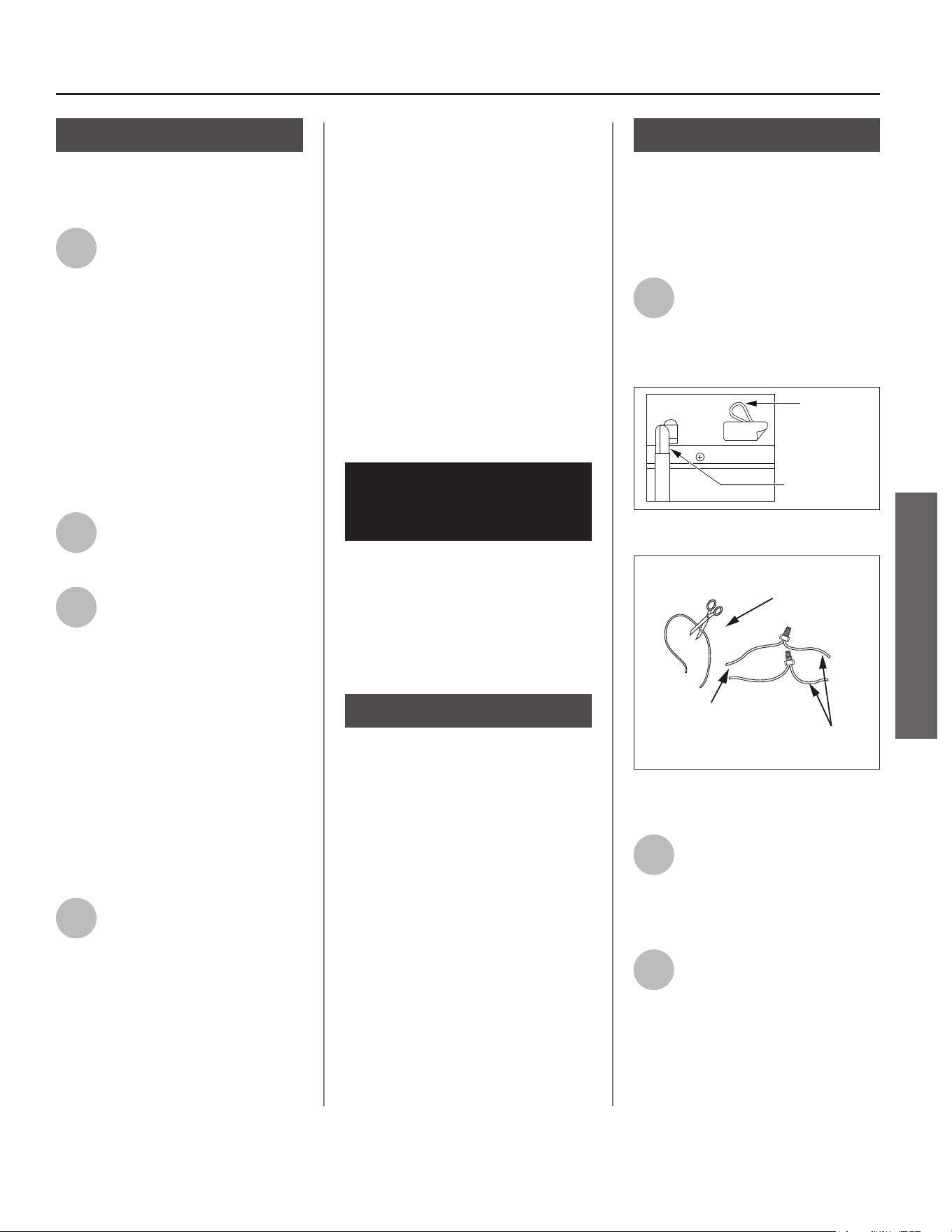
1
Locate the wiring loop next to
the condensate drain
connec on and remove label
(Figure 14). Cut the loop and strip
insula on off the two ends (Figure 15).
Condensate
Pump Wiring
(Loop located
close to Drain
Connection)
Condensate
Drain Connection
REMOVE
Figure 14 - Condensate Pump wiring.
Condensate Pump Wiring Loop
(Loop Located Close to the Drain Connections)
Wires From
Water Heater
Wires to Condensate
Pump Overflow
Shut Off Switch
Figure 15 - Wiring Loop for connection to
Condensate Pump.
2
Measure the distance from
the wiring loop to the
condensate pump. Cut two 22
AWG wires to correct length and strip
the insula on at both ends.
3
Connect the two 22 AWG
wires to the two wires on the
water heater using wire
connectors or other approved means
to make the power connec ons.
12 • Residen al Electric Water Heater Use and Care Guide
4
Connect the free ends of the
two 22 AWG wires to the
shut-off switch on the
condensate pump in accordance with
the condensate pump manufacturer’s
recommenda ons.
Step 7:
Install Condensate
Drain Line:
NOTICE: Barbed drain and fl exible
tubing for condensate drain line come
pre-installed from the factory.
• Flexible tubing must be used to
connect the condensate drain to a
suitable drain or condensate pump.
• Condensate drain line should be
installed in condi oned areas
only. Install approved insula on
on the condensate drain line to
prevent condensa on from forming
on the outside of the drain line.
Condensa on drain lines installed
in areas that are subject to freezing
temperatures should be wrapped
with a na onally recognized heat
tape. Install per manufacturer’s
instruc ons.
• Do not connect condensate drain
line with other drain or discharge
lines into a single (common) pipe
or line. Each line (condensate drain
line, temperature and pressure relief
valve discharge pipe, etc.) should be
independently run to an adequate
drain.
• Slope the condensate drain line
toward the inside fl oor drain or
condensate pump.
• The condensate drain line and
connec ons to the drain piping must
comply with all local codes.
• If a condensate pump is installed, it
should be wired to shut off the heat
pump in the event the condensate
pump fails or the fl oat switch in the
pump ac vates (see “Connec ng
the Condensate Pump Op onal
Overfl ow Shut-Off Switch” on page
11).
• Allow enough length on the 5/8” ID
fl exible plas c tubing (pre-installed
from the factory) to access an
adequate drain.
Step 8:
Connect the
Temperature and
Pressure (T&P) Relief
Valve/Pipe
Most T&P Relief Valves are pre-
installed at the factory. In some cases,
they are shipped in the carton and
must be installed in the opening
marked and provided for this purpose
and according to local codes.
WARNING! To avoid serious injury
or death from explosion, install a
T&P Relief Valve according to the
following instruc ons:
If your water heater does not have
a factory installed T&P Relief Valve,
install the new T&P Relief Valve that
came with your water heater. Do
not reuse an old T&P Relief Valve.
Install a T&P Relief Valve discharge
pipe according to local codes and the
following guidelines:
1
The discharge pipe should be
at least 3/4” (19 mm) inside
diameter and sloped for
proper drainage. Install it to allow
complete drainage of both the T&P
Relief Valve and the discharge pipe.
2
The discharge pipe must
withstand 250°F/121°C
without distor on. Use only
copper or CPVC pipe. Most homes use
copper water pipes, but some use
CPVC or cross-linked polyethylene
(PEX). Use fi ngs appropriate for the
type of pipe in your home. Do not use
any other type of pipe, such as PVC,
iron, fl exible plas c pipe, or any type
of hose.
Figure 16 - The T&P Relief Valve discharge pipe
must be installed properly and piped to an
adequate drain.
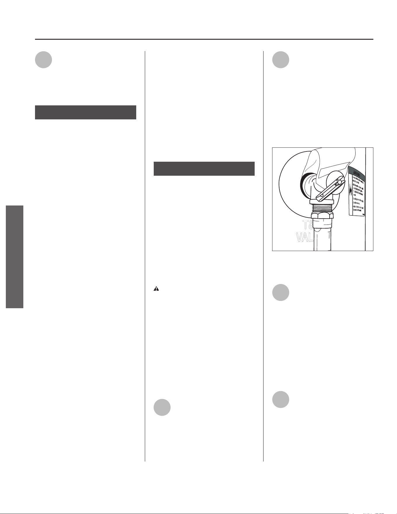
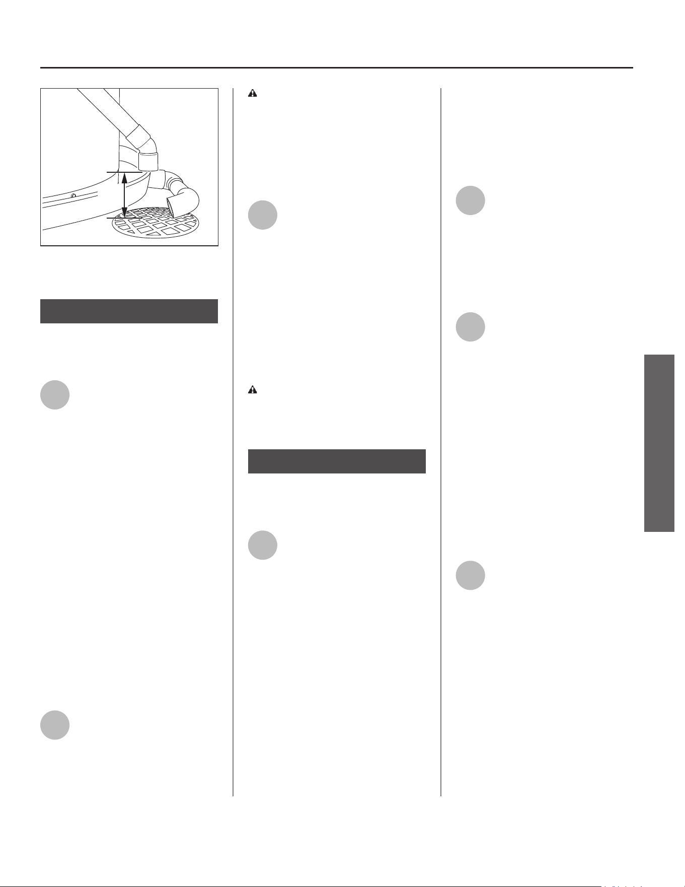
3
Terminate the discharge pipe
a maximum of 6” (15 cm)
above a fl oor drain, or
outside the building (Figure 17). Do
not drain the discharge pipe into the
drain pan; instead pipe it separately to
an adequate drain. In cold climates,
terminate the discharge pipe inside
the building to an adequate drain.
Outside drains could freeze and
obstruct the drain line. Protect the
drain from freezing.
4
Do not place any valve or
other restric on between the
tank and T&P Relief Valve. Do
not cap, block, plug, or insert any
valve between the T&P Relief Valve
and the end of the discharge pipe. Do
not insert or install any reducer in the
discharge pipe.
INSTALLATION
INSTALLATION
Residen al Electric Water Heater Use and Care Guide • 13
INSTALLATION
INSTALLATION
6.00"
MAX
Discharge
Pipe
Drain
Pipe
Figure 17 - The end of the T&P Relief Valve dis-
charge pipe must stop no more than 6” (15 cm)
above a floor drain or outside.
Step 9:
Install Shut-Off and
Tempering Valves
1
Install a manual shut-off valve
(available at your local
plumbing supplier) on the
cold water line that supplies the water
heater. Install the shut-off valve near
the water heater so that it is readily
accessible. Only use valves that are
compa ble with potable water. Use
only full-fl ow ball or gate valves. Other
types of valves may cause excessive
restric on to the water fl ow.
NOTICE: An automa c cold water
shut-off valve is available for purchase
(see the “Repair Parts” sec on of
this manual). This is to be installed
on the cold water line near the water
heater. Make sure the module cable
can be easily plugged into the Control
Assembly (within 30”/76 cm). See
included kit instruc ons found with
the automa c cold water shut-off valve
for further installa on instruc ons.
2
Install Thermosta c Mixing
Valves at each point-of-use
(for example, the kitchen sink,
bathroom sink, bath or shower).
Consult the valve manufacturer’s
instruc ons or a qualifi ed person.
WARNING! Even if the water
heater’s thermostat(s) are set to a
rela vely low temperature, hot water
can scald. Install Thermosta c Mixing
Valves at each point-of-use to reduce
the risk of scalding (see page 4 and
Figure 8).
3
For water heaters that are fed
by a solar water hea ng
system (or any other pre-
hea ng system), always install a
Thermosta c Mixing Valve or other
temperature limi ng device in the inlet
water supply line to limit water supply
inlet temperature to 120°F/49°C. Solar
water heating systems can supply
water with temperatures exceeding
170°F/77°C and may result in water
heater malfunction.
WARNING! Hot water provided
by solar hea ng systems can cause
severe burns instantly, resul ng in
severe injury or death (see page 4).
Step 10:
Connect the Water
Supply
1
Determine the type of water
pipes in your home. Most
homes use CPVC or cross-
linked polyethylene (PEX). Use fi ngs
appropriate for the type of pipe in
your home. Do not use iron or PVC
pipe – they are not suitable for potable
water.
The water inlet and outlet threaded
connec ons are steel. When
connec ng the unit to piping made of
a diff erent material, use of a dielectric
fi ng or a dielectric union conforming
to ASSE 1079 is recommended to
prevent corrosion and poten al
subsequent water leaks at or near the
connec on. Dielectric fi ngs may be
required by local plumbing codes.
IMPORTANT! A dielectric waterway
nipple is different than a dielectric
nipple and does not perform the same
function. A dielectric waterway nipple
will not protect the water heater from
corrosion.
2
The water heater can be
plumbed to either the top or
side connec ons, however,
only one op on shall be chosen
(neither top nor side connec ons may
be used in combina on). The unused
connec ons must be capped with the
caps provided.
3
Connect the cold water supply
using 3/4 inch Na onal Pipe
Thread “NPT” to the BLUE
cold water connec on on either the
top or side of the water heater.
To avoid damaging gaskets in the fl ex
lines, use a pipe wrench at the hot
and cold nipples to counter torque
when installing or removing water
connec ons. DO NOT over ghten.
NOTICE: This water heater model
contains an op onal side outlet
connec on (J-tube) that has an
orienta on mark that must line up
with arrow (in a 12 o’clock posi on).
4
Connect the hot water supply
using 3/4 inch NPT to the
corresponding RED hot water
connec on. Follow the same
connec on guidelines as for the cold
water supply.
IMPORTANT: DO NOT use top and side
connec ons in conjunc on.
Plumb the water heater using the hot
and cold connec ons located on the
top of the water heater, or the hot and
cold connec ons located on the side of
the water heater.
14 • Residen al Electric Water Heater Use and Care Guide
IF YOU HAVE COPPER PIPES:
If your home has copper water
pipes, you can solder the water pipe
connec ons or use compression
fi ngs which do not require
soldering. Compression fi ngs
are easier to install than soldering
pipe. Check with local plumbing
offi cials to determine what types of
pipe materials are suitable for your
loca on. Do not use lead-based
solder.
Compression fi ngs don’t require soldering.
NOTICE: Do not solder pipes while
they are a ached to the water
heater. The water heater’s inlet
and outlet connec ons contain
non-metallic parts which could
be damaged. The proper way to
connect the water heater to copper
water pipes is as follows:
Solder a short length of pipe (about
a foot or so) to a threaded adapter
using only 95/5 n-an mony
or equivalent solder. A ach the
threaded adaptors to the water
heater’s connec ons (using
thread sealant tape or pipe joint
compound). Connect the home’s
water pipes by soldering, keeping
the connec ons at the water heater
cool with wet rags. DO NOT over
apply joint compound.
5
Install insula on (or heat
tape) on the water pipes
especially if the indoor
installa on area is subject to freezing
temperatures. Insula ng the hot
water pipes can increase energy
effi ciency.
6
Double check to make sure
the hot and cold water pipes
are connected to the correct
hot and cold water fi ngs on the
water heater. Ensure unused hot and
cold connec ons are plugged and
capped.
7
If needed, install (or adjust)
the home’s Pressure
Reducing Valve to 50-60 psi
and install a Thermal Expansion Tank.
Figure 18 - A Pressure Reducing Valve is
required if your home’s water pressure is above
80 psi.
Figure 19 - The Thermal Expansion Tank should
be pressurized with air to match the home’s
incoming water pressure.
Recircula ng Loop
DANGER! Recircula on will cause
outlet water temperature to rise.
Water temperatures above 120°F can
cause severe burns instantly or death
from scalds. Install Thermosta c
Mixing Valves at each point-of-use to
reduce the risk of scalding.
A recircula on loop is some mes
provided in a hot water system where
it is desirable to have on demand hot
water at the fi xtures.
We do not recommend this heat
pump water heater for use in
conjunc on with recircula on loop
systems due to the wide variety
of applica ons and variability in
installa on and performance of
these systems. We can provide the
following guidance that you may use
to determine if this heat pump water
heater will operate at peak effi ciency
in your specifi c applica on.
A recircula on loop in your home
provides on demand hot water to
your fi xtures quickly but hot water
may be con nuously fl owing through
your plumbing system. If your
recircula on pipes are not insulated
well enough to prevent heat energy
loss, then your pipes will radiate heat
throughout the surrounding areas of
your home. The heat energy lost can
cause your heat pump water heater
to work con nuously to maintain the
heat in the pipes.
This heat pump water heater is
programmed with proprietary
so ware to ensure the water heater
operates at peak effi ciency. Demand
for hot water in the plumbing
system will draw hot water from the
tank causing a hea ng cycle as the
supply water temperature is much
cooler than the water in the tank.
You should consider alterna ves to
installing a heat pump water heater
in conjunc on with a residen al
recircula on loop to prevent
the water heater from running
con nuously due to the lower input
of these types of units, poten ally
causing a “no hot water” condi on.
INSTALLATION
INSTALLATION
Residen al Electric Water Heater Use and Care Guide • 15
INSTALLATION
INSTALLATION
If your recircula on loop or pump is
designed to help provide on demand
water to sinks, showers, etc., and does
not present a signifi cant con nuous
hea ng load, this heat pump water
heater can generally be used with on
demand recircula on systems if the
return inlet water temperature remains
under 105°F and you have the water
heater set for hybrid or electric modes
only.
Energy savings from this heat pump
water heater will be signifi cantly
impacted depending on condi ons
associated with the specifi c
applica on. The heat energy lost in a
recircula on loop system can cause
your water heater to run excessively.
This heat pump water heater may not
be able to accommodate demand.
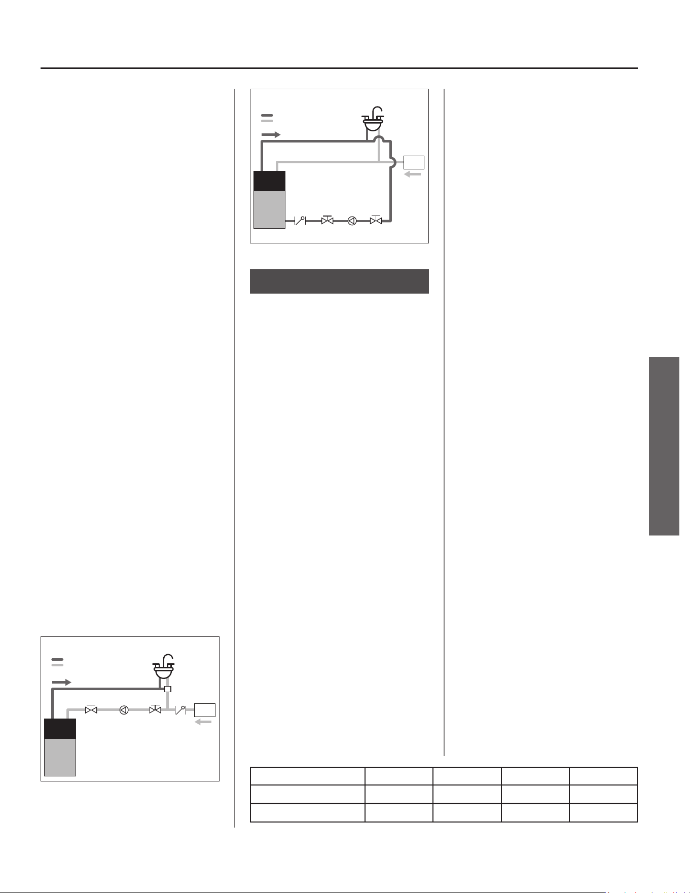
IMPORTANT: The recircula on
system or pump must comply with
local and state codes (see CA Title 24
Guidelines for installa ons in the state
of California). When implemen ng the
recircula on loop, a crossover valve
should be installed on the furthest
fi xture from the water heater, and
an on-demand inline circula on
pump should be installed on the
cold water supply line (see Figure
20). A recircula on set-up with a
dedicated return line can also be used
in conjunc on with a standard heat
pump water heater (see Figure 21).
Refer to the manufacturer’s installa on
instruc ons and requirements for the
crossover valve and circula on pump.
FIXTURE FURTHEST
FROM WATER HEATER
CROSSOVER
VALV E
CHECK
VALV E
WATER
METER
INLINE
CIRCULATION
PUMP
SHUTOFF
VALV E
SHUTOFF
VALV E
HEAT
PUMP
WATER
HEATER
HOT WATER SUPPLY
COLD WATER SUPPLY
Figure 20 - Recircula on On-Demand Line
FIXTURE FURTHEST
FROM WATER HEATER
CHECK
VALV E
WATER
METER
INLINE
CIRCULATION
PUMP
SHUTOFF
VALV E
SHUTOFF
VALV E
HEAT
PUMP
WATER
HEATER
HOT WATER SUPPLY
COLD WATER SUPPLY
Figure 21 - Recircula on Dedicated Return Line
Step 11:
Duc ng Requirements
(op onal)
Heat is absorbed from air entering
the intake side of the compressor
unit on top of the water heater and
transferred to the water inside the
storage tank. Cooler dehumidifi ed
air exi ng the exhaust side of the
compressor unit is a normal by-product
of opera on. In unvented applica ons,
a minimum installa on space of
450 ³/12.7 m³ is required, however,
if adequate provisions are made for
air exchange, this water heater may
be installed in small enclosures with a
minimum installa on space of
84 ³/2.3 m³ (see “Verify that the
Loca on is Appropriate” sec on in
this manual for more informa on
about required duc ng and vented or
louvered doors). The factory installed
duct adaptors can be used to redirect
intake and/or exhaust air from or to
other loca ons to permit installa on in
confi ned spaces, improve performance
and maintain comfort in occupied
areas of the home.
INSTALLATION LIMITATIONS
There are two duct adaptors; one
connects to the air exhaust side of the
top shroud cover (near the back of the
water heater) and one to the air intake
side of the top shroud cover (near the
front of the water heater). The two
cannot be interchanged. The inlet and
outlet duct adaptors on the water
heater accept 8” diameter duc ng. No
addi onal adaptors are needed.
7”, 6” and 5” diameter duc ng is
supported. The table below lists the
total feet of duc ng allowed.
For duct diameters smaller than 8”
diameter, the table takes into account
the duct reducer(s) and up to 10 feet
of 8” inch rigid duc ng (two elbows)
before the duct reducer(s) at the unit.
Duct reducers must be installed within
10 feet (two elbows) of the unit or
within 2 feet of the duct termina on.
IMPORTANT: A minimum length of 12”
fl exible duc ng (8” diameter) must be
installed between the duct adaptors
and any rigid duc ng.
Air can be drawn from or expelled
to the outdoors, an a c space, or to
another room inside the home.
INSTALLATION CONSIDERATIONS
The compressor unit on the water
heater is disabled when the
temperature of the air fl owing to the
intake is lower than 37°F/3°C or higher
than 120°F/49°C. These operational
parameters must be considered when
determining if a location to duct air
from/to will be suitable.
NOTICE: If the compressor unit is
disabled for long periods of me due
to air intake temperature being too
hot or too cold, the poten al energy
savings a heat pump water heater is
able to provide may be signifi cantly
reduced.
Duct Type / Diameter 8” 7” 6” 5”
Flexible 100’ 50’ 24’ —
Rigid 300’ 155’ 65’ 20’
16 • Residen al Electric Water Heater Use and Care Guide
AIR INTAKE
Outdoor air temperatures will o en
be lower than 37°F/3°C in many
regions during fall and winter months.
Attic temperatures will often exceed
120°F/49°C in many regions during
spring and summer months. For
units installed in conditioned spaces,
ducting outdoor air to the intake of
the unit may place additional load on
space heating and cooling equipment
unless the air from the exhaust is also
ducted to an alternate location.
Air being drawn from an alternate
location inside the home may cause
a negative pressure condition inside
that area. As a result, cold or hot air
from outdoors may be drawn into the
structure and place additional load
on the space heating and cooling
equipment.
AIR EXHAUST
The air exhaust from a unit installed
in a garage or any area where
solvents or other chemicals that
emit poten ally harmful fumes are
stored or automobiles are located
must never be ducted to any other
space inside the building structure.
This would include all occupied and
unoccupied spaces such as a cs or
basements. Poten ally harmful fumes
and vapors from solvents and cleaners
or automobile exhaust gases could be
introduced into living spaces.
Cold air blowing from the air exhaust
into an alternate loca on inside the
home may cause cooling discomfort.
Cold air blowing from the air exhaust
into an alternate loca on inside the
home may place addi onal load on
space hea ng equipment during fall
and winter months.
Duc ng only exhaust air to an
alternate loca on may cause a
nega ve air pressure in the installed
space. As a result, cold or hot air
from outdoors may be drawn into
the structure and place addi onal
load on the space hea ng and cooling
equipment.
Step 12:
Duc ng Installa on
(op onal)
1
Read each installa on step
and decide if you have the
necessary skills to install
intake and exhaust duc ng to and
from the heat pump water heater.
Only proceed if you can safely
perform the work. If you are not
comfortable, have a qualifi ed person
perform the installa on.
2
A er the desired length of 8”
fl exible duct has been
determined, carefully cut
completely around and through the
duct insula on jacket with a pair of
scissors. Using a pair of wire cu ers,
cut the wire inside the core duct. Fold
the duct insula on jacket back away
from the core duct.
3
Slide the core duct over the
air exhaust duct adaptor and
secure with a cable e. Seal
core duct with at least two wraps of
insula on tape over cable e.
4
Slide duct insula on jacket
back over the core duct and
the air exhaust duct adaptor.
Use insula on tape to secure the duct
insula on jacket to the air exhaust
duct adaptor. Addi onally, secure duct
insula on jacket with cable e. Repeat
procedure for the air intake duct
adaptor.
5
Add support to the duct work
as necessary with duc ng
tube hooks or as required by
local codes. Special a en on must be
given to prevent large droops in the
duct work which could allow moisture
to pool.
6
The appropriate duct
termina on shall be added to
the termina on end of the
duct. This termina on shall prevent
any debris or rodents from entering
the duct work and shall minimally
restrict airfl ow through the duc ng. In
addi on, the termina on shall be
designed to prevent rain from
entering the duct work if terminated
to the outside.
7
The fl ow area termina on
must be at least 40 sq in. to
avoid overloading the heat
pump water heater fan.
Step 13:
Verify Connec ons and
Completely Fill Tank
To remove air from the tank and allow
the tank to fi ll completely with water,
follow these steps:
1
Remove the fl ow restrictor at
the nearest hot water faucet.
This allows any debris in the
tank or plumbing system to be
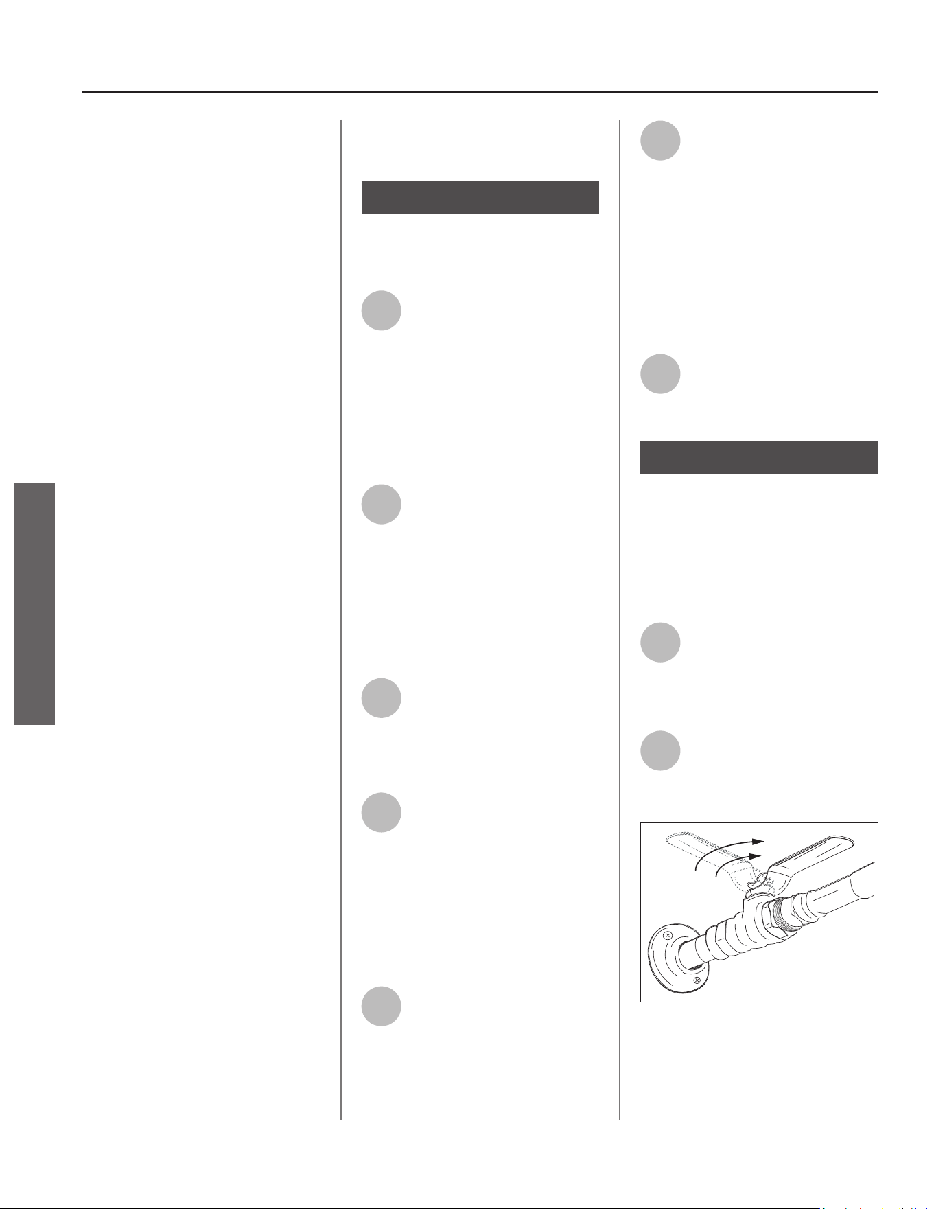
washed out.
2
Turn the cold water supply
back ON and ensure any
shut-off valves installed on
the cold water supply line are open.
Figure 22 - Fully open the cold water supply
valve (full-flow ball valve pictured above).
INSTALLATION
INSTALLATION
Residen al Electric Water Heater Use and Care Guide • 17
INSTALLATION
INSTALLATION
3
Open a hot water faucet and
allow the water to run un l it
fl ows with a full stream.
4
Let the water run full stream
for three full minutes.
5
Close the hot water faucet
and replace the fl ow restrictor.
6
Check inlet and outlet
connec ons and water pipes
for leaks. Dry all pipes so that
any drips or leaks will be apparent.
Repair any leaks. Almost all leaks occur
at connec ons and are not a tank leak.
Step 14:
Make Electrical
Connec ons
WARNING! Working on an
energized circuit can result in severe
injury or death from electrical shock.
NOTICE: Do not turn electrical power
on unless you are sure all of the air
is out of the tank and the tank is
completely full of water. Although this
water heater is equipped with “Dry-
Fire” protec on, be certain all air is
purged from the tank before making
any electrical connec ons.
1
Be sure the electrical power
to the water heater is turned
OFF at the circuit breaker
panel (or remove the circuit’s fuses).
2
Using a non-contact circuit
tester, check the wiring to
make certain the power is OFF
and the circuit is not energized.
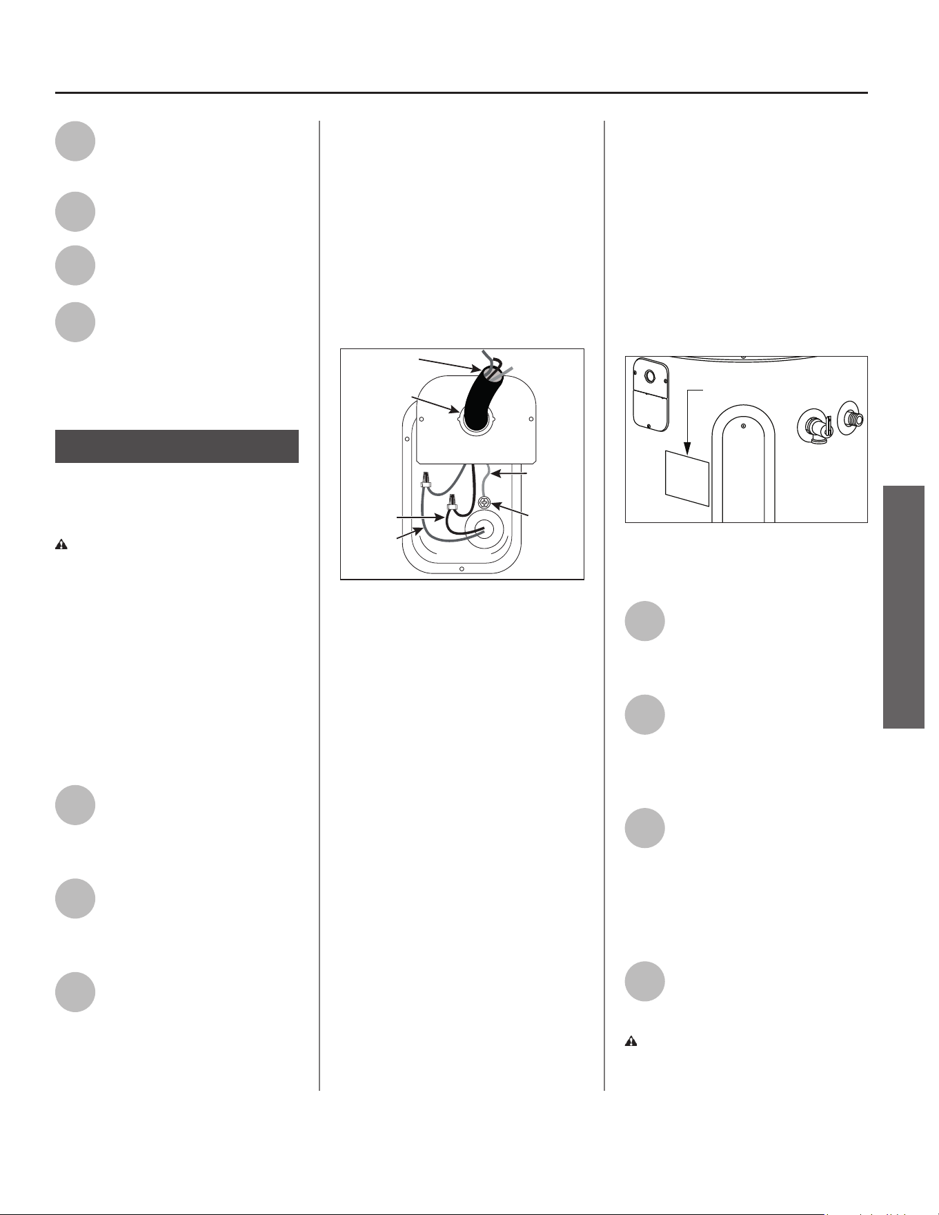
3
This water heater requires a
208/240 VAC single phase 30
amp power supply, at 50Hz or
60Hz. Check the water heater’s data
plate (Figure 24) and ensure that the
home’s voltage, wiring size (ampacity)
and circuit breaker ra ng and type are
correct for this water heater. Refer to
the wiring diagram located on the
water heater, and on page 38 of this
manual, for the correct electrical
connec ons. Ensure that wire sizes,
type, and connec ons comply with all
applicable local codes. In the absence
of local codes, follow NFPA-70 and the
current edi on of the Na onal Electric
Code (NEC).
1/2” Conduit
Opening
Green
Ground
Screw
Green
Ground
Wire
Red Wire
Black Wire
Power Supply
Connector
Figure 23 - Connecting the electrical wires
(bottom cover to electrical junction box removed
for clarity).
If metal conduit is used for the
grounding conductor:
• The grounding electrode conductor
shall be 10 gauge solid copper wire.
The copper wire shall be of one
con nuous length without a splice
or joint.
• Rigid metal conduit, intermediate
metal conduit, or electrical metallic
tubing may be used for the
grounding means if conduit or tubing
is terminated in fi ngs approved for
grounding.
• Flexible metal conduit or fl exible
metallic tubing shall be permi ed
for grounding if all the following
condi ons are met:
I. The length in any ground return
path does not exceed 6 feet/1.8 m.
II. The circuit conductors contained
therein are protected by
overcurrent devices rated at 30
amperes.
III. The conduit or tubing is terminated
in fi ngs approved for grounding.
For complete grounding details and
all allowable excep ons, refer to the
current edi on of the Na onal Electric
Code NFPA-70.
Data Plate
Figure 24 - The water heater’s electrical
requirements can be determined from the data
plate.
4
Remove the top and bo om
covers on the electrical
junc on box on the side of
the water heater.
5
Install wiring in an approved
conduit (if required by local
codes). Use a UL listed or CSA
approved strain relief to secure the
electrical wiring to the water heater.
6
Connect the ground wire to
the green ground screw.
Connect the home’s two
power wires to the water heater’s two
power wires. Use suitable wire
connectors or other approved means
to make the power connec ons.
7
Replace the junc on box
covers and secure with the
screws provided.
WARNING! Be sure the cover is
secured to reduce the risk of fi re and
electric shock.
18 • Residen al Electric Water Heater Use and Care Guide
Step 15:
Installing the Leak
Detec on Sensor
The Leak Detec on Sensor (LDS) does
not provide protec on against a water
leak, it only provides no fi ca on that
water is present in the loca on of the
sensor. When a leak is detected, the
Control Assembly will display an error
code accompanied by a fl ashing light
and audible signal. If the presence
of water is indicated, disconnect
power to the water heater, turn OFF
the incoming water and address the
source of the leak before returning
the unit to service. See included kit
instruc ons found with the LDS for
detailed installa on instruc ons.
1
Plug the LDS into the
connec on port next to the
lower element access panel.
2
A ach the LDS to the heater
or drain pan using the tape
on the back of the LDS.
Ensure the metal probes point down.
3
Use the included wire clamps
to organize the wires.
Step 16:
Adjus ng the
Temperature
With the installa on steps completed,
you may adjust the water heater’s
temperature se ng if desired.
1
Turn the electric power back
ON. Remove/pull out the
ba ery protec ve tab from
the le side of the Control Assembly.
2
Set the thermostat to the
desired temperature on the
Control Assembly (see
“Adjus ng the Control Assembly’s
Opera onal Modes” on page 21). The
set point on this water heater has
been factory set to approximately
120°F/49°C to reduce the risk of scald
injury. You may wish to set a higher
temperature to provide hot water for
automa c dishwashers or laundry
machines, to provide more hot water
capacity, and to reduce bacterial
growth. Higher tank temperatures
(140°F/60°C) kill bacteria that cause a
condi on known as “smelly water”
and can reduce the levels of bacteria
that cause water-borne diseases.
WARNING! Higher temperatures
increase the risk of scalding, but even
at 120°F/49°C, hot water can scald
(see page 4 and Figure 25).
If you increase the water heater’s
temperature se ng, install
Thermosta c Mixing Valve(s) at each
point-of-use to reduce the risk of
scalding.
MIX
Figure 25 - Adjust Thermostatic Mixing Valves at
each point-of-use to 120°F/49°C or lower.
3
Wait for the water to heat
up. It may take several hours
for a tank of cold water to
heat up. If you have no hot water
a er two hours, refer to the
“Troubleshoo ng” sec on (beginning
on page 25).
WARNING! If you have increased
the temperature se ng and the
Thermosta c Mixing Valves are not
set properly (or not installed) you
could scald yourself while checking
the temperature.
4
Check water temperature at
several points in your home
(for example, the bathtub
faucet, shower, or lavatory sink) and
adjust the Thermosta c Mixing Valves
as needed. If you are not sure how to
adjust the Thermosta c Mixing Valve
se ngs, or are not sure if you have
Thermosta c Mixing Valves, contact a
qualifi ed person.
Post Installa on
Review
1
Understand how to use the
Control Assembly to set the
various modes and func ons.
2
Hybrid Mode is the
recommended Opera ng
Mode. Understand the
various Opera ng Modes and which
mode may be best, based on ambient
temperature and hot water demands.
3
Understand the importance
of rou ne inspec on/
maintenance of the
condensate drain pan and line. This is
to prevent any possible drain line
blockage resul ng in the condensate
drain pan overfl owing.
4
To maintain op mal
opera on, check, remove and
clean the air fi lter as needed.
5
The installa on Instruc ons
and Use and Care Guide
should be kept with the
water heater for reference.
INSTALLATION
INSTALLATION
Residen al Electric Water Heater Use and Care Guide • 19
OPERATION
Start-up and Opera on
NOTICE: The default opera ng mode
is Hybrid Mode. To select a diff erent
mode, see “Adjus ng the Control
Assembly’s Opera onal Modes” on
page 21.
1
Turn the electric power ON at
the circuit breaker panel, or
fuse box. Power to the water
heater will allow the water heater to
run a system diagnos c. This typically
takes several minutes.
NOTICE: The water heater will conduct
a system diagnos c (approximately
seven (7) to ten (10) minutes) each
me power is applied from an off
state. Normal opera on will begin
a er the system diagnos c has been
completed. If the system diagnos c
yields any codes, reference the
diagnos c codes sec on in this manual
(see pages 25-27).
2
The diagnos c sequence
typically takes seven (7) to ten
(10) minutes. During this
period the Control Assembly will
display a series of single, alterna ng
dashes repe vely. Once the
diagnos c sequence has fi nished, the
fan will turn on.
NOTICE: The heat pump’s fan will
not turn on if the average water
temperature in the tank is less than
55°F/13°C and/or the ambient air
temperature is above 120°F/49°C, or
below 37°F/7°C. Should the internal
diagnos cs detect the heat pump is
out of opera onal range, the Control
Assembly will display the code HPO.
Normal opera on will be restored
once heat pump is within opera onal
range.
3
Set the desired opera onal
mode. For typical installa ons,
the factory default mode
(Hybrid Mode) off ers the best
combina on of effi ciency and hot
water delivery.
Opera ng Mode
Descrip ons
The opera ng modes can be changed
by pressing the bu on for any desired
mode (Figure 26 on page 21). The
Opera on Mode Indica on Light will
turn on when the relevant mode is
selected.
This unit is equipped with technology
that senses the hot water demand
from the unit. While in Heat Pump or
Hybrid Mode, during normal usage,
the unit will operate the heat pump
for maximum effi ciency. In Hybrid
Mode, during periods when the
water usage is above normal, this unit
has the ability to use one element
(upper or lower) and the heat pump
simultaneously to help improve
recovery. This transi on is seamless
and will go unno ced.
General Opera on
IMPORTANT: On the ini al start-up
of the unit, the water heater will go
through a seven (7) to ten (10) minute
diagnos c period prior to hea ng the
water.
NOTICE: If the water is warm/hot, the
unit will not go through the diagnos c
period.
The primary func on of the Control
Assembly is to heat the water in the
tank un l it reaches the temperature
set point. The water heater has
three means of hea ng the water:
the elements, the heat pump, and a
combina on of the elements and heat
pump.
The control logic of the Control
Assembly is designed so that the
heat pump will always have priority
over the elements. The temperature
regula on will not be performed
un l a er Dry-Fire detec on tes ng
indicates that there is suffi cient water
in the tank.
Vaca on Mode
To save energy, select Vaca on Mode
to lower the temperature se ng on
the thermostat if you plan to be away
for an extended me.
NOTICE: Vaca on Mode has a fi xed set
point of 50°F/10°C.
When Vaca on Mode is selected, the
vaca on mer will be displayed. The
default vaca on days are preset at 7
days. Press the Up and Down bu ons
to modify the mer to desired number
of vaca on days (se ng range: 1 to
99 days or permanently ON). The
vaca on mer will blink on the display;
press the Enter bu on to confi rm the
vaca on mer. To deac vate Vaca on
Mode, press the Vaca on Mode bu on
to return to the previous opera ng
mode or press the bu on for any other
desired mode.
When the vaca on days decrease to 9
hours remaining, the Control Assembly
will automa cally switch to the
previously selected mode.
NOTICE: Normally, the display will only
show the remaining vaca on days.
WARNING! Hydrogen gas builds up
in a hot water system when it is not
used for a long period (two weeks
or more). Hydrogen gas is extremely
fl ammable. If the hot water system
has not been used for two weeks or
more, open a hot water faucet for
several minutes at the kitchen sink
before using any electrical appliances
connected to the hot water system.
Do not smoke or have an open fl ame
or other igni on source near the
faucet while it is open.
OPERATION

20 • Residen al Electric Water Heater Use and Care Guide
Heat Pump Mode
Provides the highest effi ciency and
lowest cost opera on by using only
the heat pump for hea ng. Recovery
me and effi ciency will vary with
ambient temperature and rela ve
humidity. Effi ciency will be greatest,
and recovery quickest, when both
are high. At lower temperatures and
rela ve humidity levels, effi ciency will
be lower and recovery will take longer.
Heat pump opera on is allowed
between 37°F/3°C to 120°F/48.9°C
ambient temperature. At ambient
temperatures lower than 37°F/3°C
and greater than 120°F/48.9°C, the
heat pump will not operate. Similarly,
if the average water temperature
in the tank is less than 55°F/13°C,
the heat pump will not operate. The
Control Assembly will display the
code HPO, and the unit will operate
in Electric Mode un l ambient air and
water temperatures return to the safe
opera ng range of the heat pump.
Hybrid Mode
This is the default, recommended
se ng combining high energy
effi ciency with reduced recovery
me. This mode uses the heat pump
as the primary hea ng source. One
of the hea ng elements (upper or
lower) will provide supplementary
hea ng if demand exceeds a
predetermined level so that the set
point temperature can be recovered
more quickly.
Electric Mode
The water heater func ons as a
conven onal electric unit, relying on
only the elements for heat. This mode
may be useful in periods of increased
hot water demands. When Electric
Mode is selected, the dura on mer
will be displayed. The default Electric
Mode days are preset at 3 days. Press
the Up and Down bu ons to modify
the mer to the desired number of
Electric Mode days (se ng range: 1
to 7 days). The mer will blink on the
display; press the Mode/Enter bu on
to confi rm the Electric Mode mer.
NOTICE: Do not shut off power to the
unit for extended periods of me.
If power must be turned off for an
extended period of me, turn OFF
the power to the water heater at the
circuit breaker/fuse box, and then
drain the tank completely.
Other Controls
HEAT PUMP DEFROSTING
INDICATION:
There will be frost accumula ng
on the evaporator when the heat
pump is operated under low ambient
temperatures. The controller will
order the unit to enter defros ng
cycle to op mize the heat pump
opera on performance. During
the defros ng period, the Control
Assembly will display ICE as an
indica on.
OUT OF HEAT PUMP OPERATION
RANGE:
The Control Assembly will display HPO
as an indica on that the ambient and/
or water temperature condi on is out
of the heat pump opera on range.
NOTICE: The display will go into
“Sleep Mode” for energy saving if
there is no opera on on any bu on
for 15 minutes. All of the display and
lights will be turned off except for the
“Opera onal Mode Indica on Light,”
which will remain illuminated while
the unit is powered on. The unit can
be awakened by pressing any bu on.
Your Heat Pump Water Heater is
equipped with an EcoPort CTA-2045
communica on port. Contact your
local electric u li es company for
par cipa on and plug in module
availability and to learn more
about poten al energy savings
opportuni es.
OPERATION
OPERATION
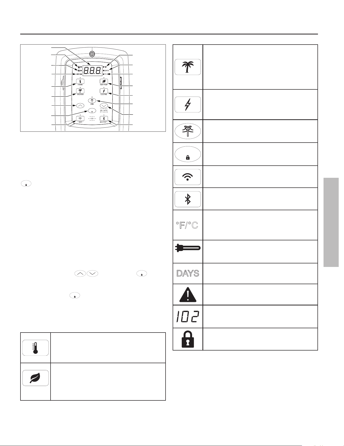
Residen al Electric Water Heater Use and Care Guide • 21
OPERATION
Heating Cycle
LED Indicator
Control Assembly
Lock LED Indicator
Water Temperature
Set Point
Temperature
Down (Decrease)
Button
Temperature
Up (Increase)
Button
Wi-Fi
Button
Grid Enabled
Button W/LED
Indicator
Heat Pump Mode
Button
Celsius LED
Indicator
Fahrenheit LED
Indicator
Hybrid Mode
Button
Days LED
Indicator
Error LED
Indicator
ENTE
R
Vacation Mode
Button
Electric Mode
Button
LCD Display Panel
Enter/Lock Button
Bluetooth
Button
Figure 26 - Control Assembly
ADJUSTING THE CONTROL ASSEMBLY’S
OPERATIONAL MODES
If locked, the opera ng modes can be changed by holding the
ENTER
bu on for approximately 3 seconds, then touching the
desired mode icon on the Control Assembly (Figure 26).
WATER TEMPERATURE ADJUSTMENT
IMPORTANT: On the ini al start-up of the unit, the water
heater will go through a seven (7) to ten (10) minute diagnos c
period prior to hea ng the water. Before a emp ng to adjust
the thermostat, read the “Important Safety Informa on”
sec on on page 4. If the instruc ons are not clear, contact a
qualifi ed service technician.
The water temperature can be adjusted from 95°F/35°C to
150°F/65°C by pressing followed by the
ENTER
bu on
to set the desired temperature. The Control Assembly is
unlocked by default. To lock the display a er se ng the
parameters, hold the
ENTER
bu on for 3 seconds.
°F/°C SWITCH: Press and hold the “Temperature Down” bu on,
in combina on with the “Enter” bu on, for 3 seconds to switch
temperature unit between Fahrenheit and Celsius.
HYBRID MODE - System default mode. Pressing this
bu on will allow high effi ciency heat pump opera on
with supplementary hea ng from a backup hea ng
element during periods of high demand.
HEAT PUMP MODE - Provides the highest effi ciency
and lowest cost opera on by using only the heat
pump for hea ng while in the safe ambient opera ng
range of the heat pump (between 37°F/3°C to
120°F/48.9°C).
VACATION MODE - The Control Assembly adjusts the
temperature set point to approximately 50°F/10°C.
This mode is recommended when the water heater
is not in use for a long period of me. This mode
minimizes energy consump on and prevents the
water heater from freezing during cold weather.
ELECTRIC MODE - The water heater func ons as
a conven onal electric unit, relying on only the
elements for heat. This mode may be useful in
periods of increased hot water demand.
SMART GRID CONTROL - Pressing this bu on will
enable or disable a request for grid control (see page
24).
ENTER
CONTROL ASSEMBLY LOCK - Holding this bu on for
more than 3 seconds switches the lock mode on or
off .
Wi-Fi - Press this bu on once to ac vate the Wi-Fi
signal.
BLUETOOTH - Press this bu on once to ac vate the
Bluetooth signal.
°C
°F/
°F/°C - Press and hold the “Temperature Down”
bu on, in combina on with the “Enter” bu on,
for 3 seconds to switch temperature unit between
Fahrenheit and Celsius.
HEATING CYCLE INDICATOR - Indicates the water
heater is in a hea ng cycle and either the elements
are energized or the heat pump is opera ng.
DAYS
DAYS - Indicates the number of days (1 to 99+) the
unit will be set in vaca on mode.
CAUTION INDICATOR - Indicates when there is a
Warning/Fault.
FAULT CONDITION - Will display a three digit fault
code with Alert Icon Flashing (see Diagnos c code
chart on page 25).
LOCK - Indicates the control assembly is locked.
OPERATION
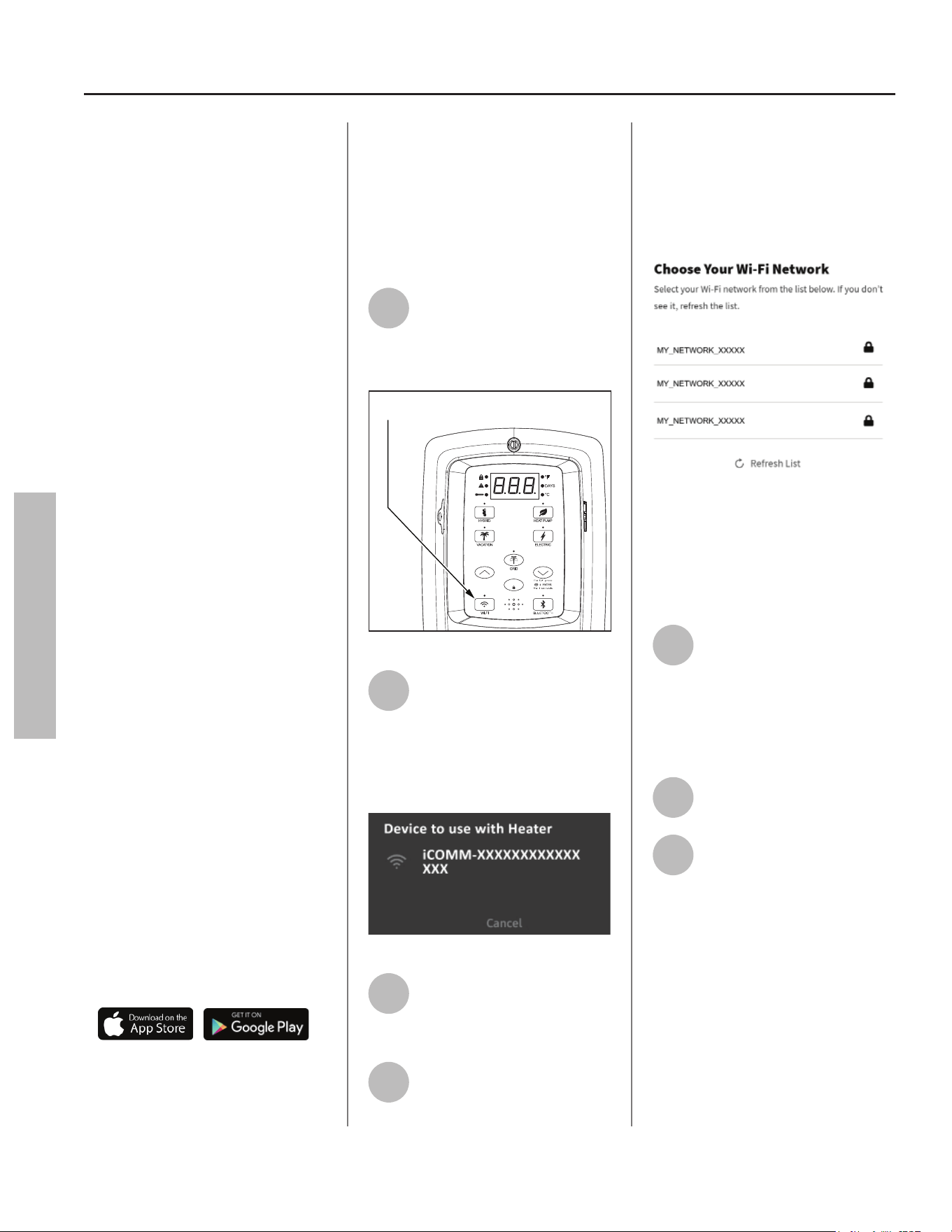
22 • Residen al Electric Water Heater Use and Care Guide
Wi-Fi
(Control Assembly)
This water heater comes equipped
with the iCOMM™ remote monitoring
system. It allows users to monitor
cri cal opera ons and diagnose issues
remotely using the manufacturer’s
water heater app (available for IOS and
Android).
The iCOMM system can automa cally
no fy selected personnel via email
and/or cellular phone text messages if
opera onal problems occur.
It is recommended the water heater
app be installed on the homeowner’s
device prior to se ng up the Wi-Fi
func on on this water heater.
IMPORTANT: By enabling and
connec ng your water heater to
Wi-Fi, you are gran ng permission to
the manufacturer to push “over-the-
air” (OTA) updates to the water heater
and to collect telemetry data regarding
the water heater. The OTA updates may
be pushed periodically to address bugs
and provide security patches. Refer
to the Terms and Condi ons at www.
aosmith.com/UƟ lity-Pages/Terms-
and-CondiƟ ons/ for more details. Also,
refer to www.aosmith.com/Privacy-
Policy/ for more informa on about
how we collect and use data.
Wi-Fi Set Up:
The Wi-Fi signal is set to OFF by default
and will not produce a signal un l
ac vated.
NOTICE: Have the router SSID and
password ready.
• Download the iCOMM U li es app
for your smart phone.
• Launch the iCOMM U li es app on
your smart phone, then follow the
simple steps. The iCOMM U li es
app makes it easy to set up, program
and control your water heater.
• Create an account or log in to your
exis ng account and tap the “add a
water heater” bu on.
• When the app prompts you to
ac vate the Wi-Fi signal, proceed
with the following steps:
1
To ac vate the Wi-Fi signal,
press the Wi-Fi bu on once.
The LED will blink on and off
in 1/2 second intervals. Wi-Fi will
ac vate pairing mode (Figure 27).
ENTE
R
Pressing the Wi-Fi button once will activate
the Wi-Fi signal for 15 minutes.
Figure 27 - Wi-Fi Control
2
The app will display a
temporary Wi-Fi network to
connect to your device. Select
the network that matches the water
heater DSN value, and your device will
connect to the Wi-fi radio on the
Control Assembly:
Figure 28 - Select Temporary Network
3
The app will begin the
communica on process of
linking your water heater to
your Wi-Fi router.
4
Select your preferred Wi-Fi
network from the list on the
app. LED will pulse from dim
to bright when a emp ng to connect
to local network. If the app does not
prompt you with a list of available
Wi-Fi networks, access Wi-Fi se ngs
on your device and select your
preferred network.
Figure 29 - Select Your Wi-Fi Network
NOTICE: Your water heater does not
support the following:
• 5GHz Wi-Fi
• WPA3 Security Protocol
5
The app will a empt to
connect with your Wi-Fi
network. We recommend
connec ng to a Wi-Fi network that
has been secured with a password.
The LED will hold solid when
connected.
6
The app will display the water
heater temperature set point.
7
Confi gure the water heater
Set Point, Mode, and Time of
Use Rate Plan if applicable.
NOTICE: If the Wi-Fi signal is to be
terminated, press and hold the Wi-Fi
bu on for 3 seconds. The Control
Assembly will beep once. This will
turn the Wi-Fi signal off . The Control
Assembly resets and the LED display
will turn off . Press and hold the Wi-Fi
bu on for 9 seconds to remove the
original connected network from the
Control Assembly memory.
OPERATION
OPERATION
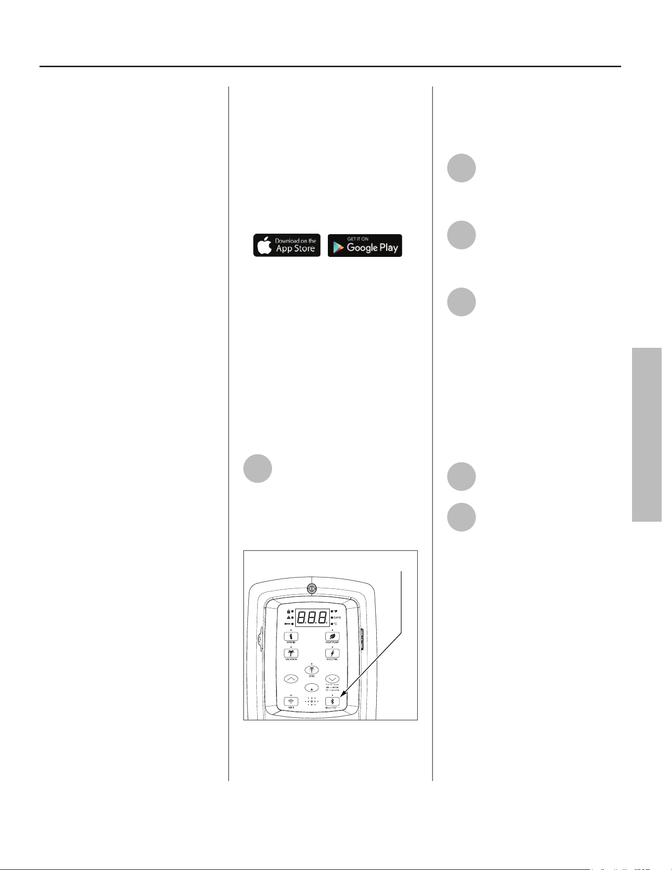
Residen al Electric Water Heater Use and Care Guide • 23
OPERATION
Bluetooth
(Control Assembly)
This water heater comes equipped
with the iCOMM™ remote monitoring
system. It allows users to monitor
cri cal opera ons and diagnose issues
remotely using the manufacturer’s
water heater app (available for IOS and
Android).
The iCOMM system can automa cally
no fy selected personnel via email
and/or cellular phone text messages if
opera onal problems occur.
It is recommended the water heater
app be installed on the homeowner’s
device prior to se ng up the
Bluetooth func on on this water
heater.
IMPORTANT: By enabling and
connec ng your water heater to
Bluetooth, you are gran ng permission
to the manufacturer to push “over-
the-air” (OTA) updates to the water
heater and to collect telemetry data
regarding the water heater. The OTA
updates may be pushed periodically
to address bugs and provide security
patches. Refer to the Terms and
Condi ons at www.aosmith.com/
UƟ lity-Pages/Terms-and-CondiƟ ons/
for more details. Also, refer to www.
aosmith.com/Privacy-Policy/ for more
informa on about how we collect and
use data.
Bluetooth Set Up:
The Bluetooth signal is set to OFF by
default and will not produce a signal
un l ac vated.
NOTICE: Have the device SSID and
password ready.
• Download the iCOMM U li es app
for your smart phone.
• Launch the iCOMM U li es app on
your smart phone, then follow the
simple steps. The iCOMM U li es
app makes it easy to set up, program
and control your water heater.
• Create an account or log in to your
exis ng account and tap the “add a
water heater” bu on.
• When the app prompts you to
ac vate the Bluetooth signal,
proceed with the following steps:
1
To ac vate the Bluetooth
signal, press the Bluetooth
bu on once. The LED will
blink on and off in 1/2 second
intervals. Bluetooth will ac vate
pairing mode (Figure 30).
ENTE
R
Pressing the Bluetooth button once will activate
the Bluetooth signal for 10 minutes.
Figure 30 - Bluetooth Control
NOTICE: Once ac vated, the Bluetooth
signal will automa cally terminate
a er 10 minutes if no a empt to pair
your device is made.
2
Select the op on in the app to
begin linking your device with
the Bluetooth radio on the
Control Assembly.
3
The app will begin the
communica on process of
linking your water heater to
your Bluetooth device.
4
The app will a empt to
connect with your Bluetooth
device. We recommend
connec ng to a Bluetooth device that
has been secured with a password.
The LED will hold solid when
connected.
NOTICE: Once connected, the
Bluetooth signal will automa cally
terminate a er 30 minutes of
inac vity.
5
The app will display the water
heater temperature set point.
6
Confi gure the water heater
Set Point, Mode, and Time of
Use Rate Plan if applicable.
NOTICE: If the Bluetooth signal is to
be terminated, press and hold the
Bluetooth bu on for 3 seconds. The
Control Assembly will beep once.
This will turn the Bluetooth signal off .
The Control Assembly resets and the
LED display will turn off . The original
connected device has been removed
from the memory of the water heater
Control Assembly.
OPERATION
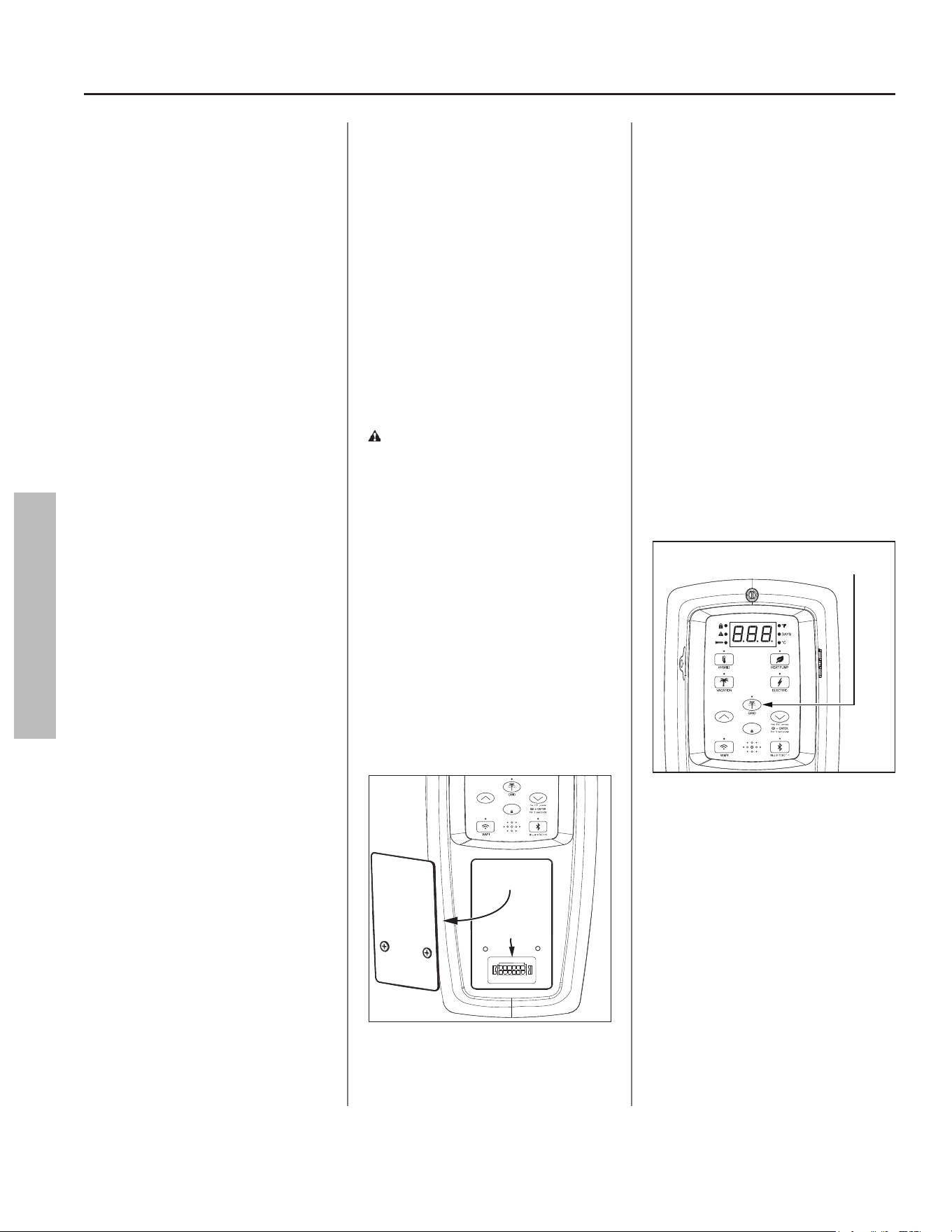
24 • Residen al Electric Water Heater Use and Care Guide
Smart Grid Technology
The electric Smart Grid will enable
signifi cant improvements in electric
power reliability and quality through
reduc on of peak power demand,
while providing consumers the
knowledge and ability to manage
their energy consump on and u lity
costs. According to the Department
of Energy (DOE), since 1982 the
growth in peak electricity demand
has exceeded power transmission
growth. This has caused more
frequent blackouts and service
interrup ons, as well as an increase in
the costly reserve capacity the power
grid requires to meet higher peak
demands. The increased demand for
electrical power across the na on has
also led to higher peak u lity costs.
Smart appliances are one way to
help mi gate this problem. By using
advanced digital communica on
technologies, smart appliances will
be able to communicate with local
power companies or home energy
systems, and react accordingly to
save energy and money. For example,
during peak demand periods, the
water heater may pause or delay its
power consump on and thus reduce
the load on the smart u lity grid.
Addi onally, smart appliances will
also communicate with consumers to
let them know how much energy they
are consuming. This will eventually
allow consumers to control their
appliances, manage energy usage, and
ul mately save money.
EcoPort CTA-2045,
Smart Grid Control
(Where Available)
Where available, grid communica on
adaptors called Universal
Communica on Modules (UCM)
may be supplied by the local power
company or purchased from leading
retailers. A UCM is a direct digital
thermostat that provides integrated
control of the unit’s thermostat.
Please contact your local power
company for more informa on.
WARNING! Electrical Shock Hazard.
Disconnect power before servicing.
Replace all parts and panels before
opera ng. Failure to do so can result
in death or electrical shock.
To ac vate Smart Grid Control, turn
OFF electric power to the water
heater at the circuit breaker or fuse
box. Using a non-contact circuit
tester, check the power wires to make
certain the power is OFF. Remove
the cover over the grid connec on
pins and plug in the UCM grid
communica on adaptor and return
power to the water heater at the
circuit breaker or fuse box (Figure 31).
Remove
Panel
Grid Connection Pins
ENTE
R
Figure 31 - Accessing EcoPort CTA-2045
communication port.
NOTICE: Use only approved grid
communica on adaptors. This
will enable the power company to
communicate the peak demand
periods for the water heater’s power
usage.
A er this connec on is made, the grid
control is automa cally enabled. Press
the “Enter” bu on to confi rm UCM is
present. This ac on will be followed
by a solid LED from the grid indicator
(Figure 32).
Enabling this feature will allow
acceptance of the power company
communica on grid management
requests.
NOTICE: The LED will blink when the
power company has control of the
unit.
ENTE
R
Pressing the Smart Grid Control
button will enable and/or disable
a request for grid control.
Figure 32 - Smart Grid Control Button
To disable (override) grid control,
press the “Smart Grid Control”
bu on (Figure 32). This ac on will be
followed by a 72 hour mer. Remove
CTA 2045 UCM. Press the “Enter”
bu on to confi rm the disconnec on.
The LED will turn off .
NOTICE: If the CTA 2045 UCM is
not removed followed by pressing
the “Enter” bu on, the grid will be
enabled automa cally once the 72
hour mer has expired.
OPERATION
OPERATION
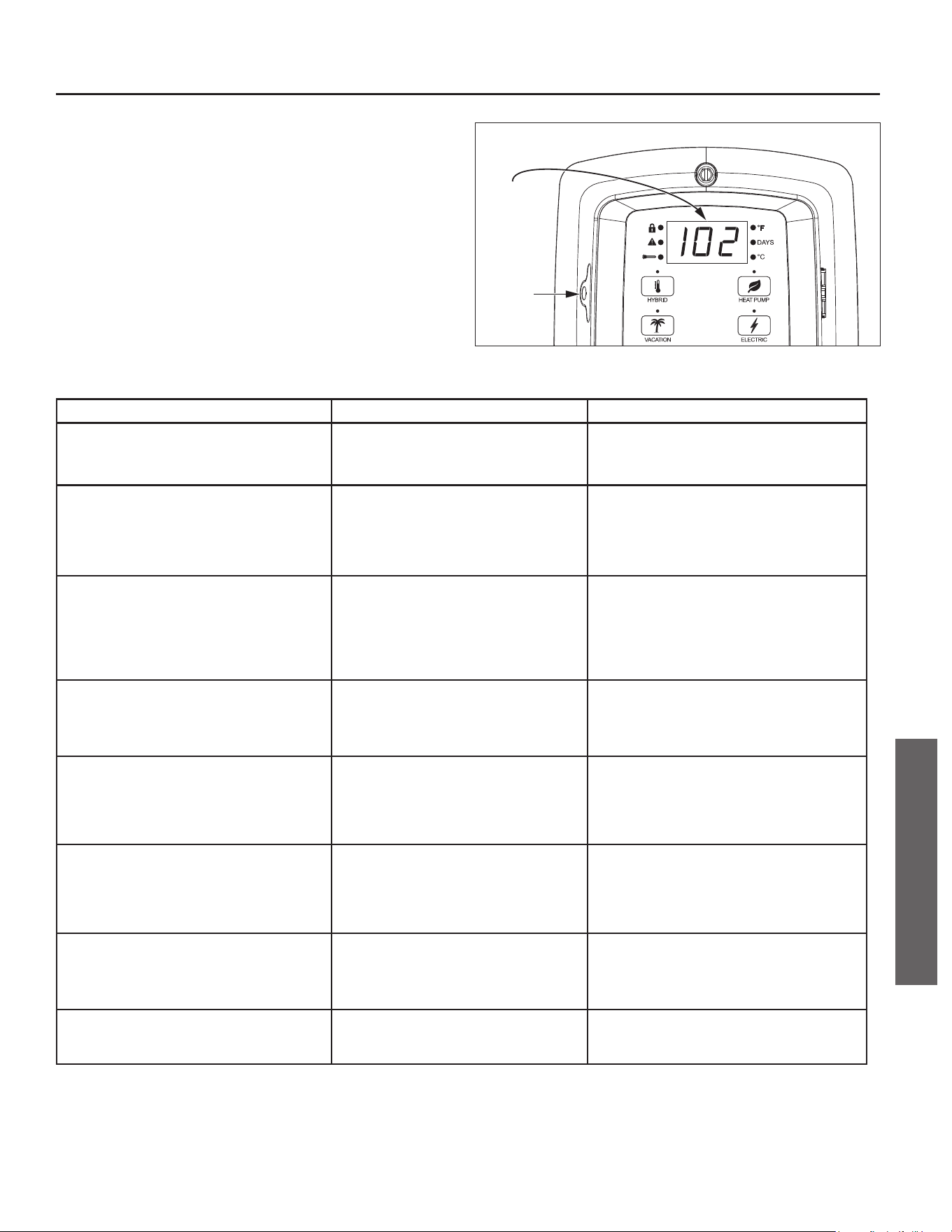
Residen al Electric Water Heater Use and Care Guide • 25
TROUBLESHOOTING
CONTROL ASSEMBLY DIAGNOSTIC
CODE CHART
IMPORTANT: Before a emp ng to adjust the thermostat, read
the “Important Safety Informa on” sec on on page 4. If the
instruc ons are not clear, contact a qualifi ed person.
Error
Code
Battery
Tray
Figure 33 - Control Assembly Diagnostic Coding.
ERROR CODE INDICATES CORRECTIVE ACTION*
No Error Code Displayed
Not Enough Hot Water
High usage, plumbing leak, operating mode
adjustment
1. Check for plumbing leak.
2. Adjust temperature; see scald warnings on heater
and in manual.
3. Contact a qualified person to perform a volume test.
No Error Code Displayed
Water Too Hot
Water temperature set too high or grounded
element
1. Reduce temperature setting; or
2. Turn OFF electrical power at the breaker.
3. Check element circuits for resistance of 5-25 ohms
(replace if required, see page 34).
4. Turn ON electrical power at breaker.
5. If the error persists, contact a qualified person.
No Error Code Displayed
No Hot Water
No power, control panel or thermostat operation 1. Turn OFF electrical power at breaker.
2. Unplug and reconnect 24 pin connector.
3. Turn ON electrical power at breaker.
4. Contact a qualified person to verify correct voltage
to unit.
NOTICE: If the control panel was not connected via Wi-
Fi or Bluetooth, the time will need to be set.
001 with an alert Icon flashing.
(also flashing red LED and beeper.)
Dry-fire, electrical power on with the tank not
completely full of water
1. Turn OFF electrical power at breaker. Add water,
open a hot water faucet to bleed all air until water
flows without air bursts.
2. Turn ON electrical power at breaker.
3. See “Important Safety Information” on page 4.
003 with an alert Icon flashing.
(also flashing red LED.)
Upper thermistor sensor failure. Upper thermistor
sensor is mounted to tank and located above
upper element.
NOTICE: The Control Assembly will go into Limp
Mode 1 until the failure is corrected. See page 28.
1. Turn OFF electrical power at the breaker.
2. Check electrical connections at Control Assembly
board.
3. If there are no issues with the wiring, replace the
thermistor.
4. Turn ON electrical power at breaker.
004 with an alert Icon flashing.
(also flashing red LED.)
Lower thermistor sensor failure. Lower thermistor
sensor is mounted to tank and located above
lower element.
NOTICE: The Control Assembly will go into Limp
Mode 2 until the failure is corrected. See page 28.
1. Turn OFF electrical power at the breaker.
2. Check electrical connections at Control Assembly
board.
3. If there are no issues with the wiring, replace the
thermistor.
4. Turn ON electrical power at breaker.
006 with an alert Icon flashing.
(also flashing red LED and beeper.)
Internal Processor Error
- Frequency Fault
- Standard AD Reference Fault
- Non-Volatile Memory Fault
-
Crystal Fault
1. Turn OFF electrical power at the breaker. Now turn
ON electrical power to see if error clears. If error
has not cleared, turn OFF electrical power at the
breaker and replace the Control Assembly.
2. Turn ON electrical power at breaker.
009 with an alert Icon flashing.
(with flashing red LED.)
Power supply voltage is too low
NOTICE: The Control Assembly will go into Limp
Mode 3 until the failure is corrected. See page 28.
Check for loose electrical connections, refer to “Power
Cycling the Unit” on page 31.
TROUBLESHOOTING
26 • Residen al Electric Water Heater Use and Care Guide
ERROR CODE INDICATES CORRECTIVE ACTION*
021 with an alert Icon flashing.
(also flashing red LED.)
Upper element circuit failure. Lower element is still
operable
NOTICE: The Control Assembly will go into Limp
Mode 1 until the failure is corrected. See page 28.
1. Turn OFF electrical power at the breaker.
2. Check element circuits for resistance of 5-25 ohms
(replace if required, see page 34).
3. Check wires at elements, thermostat and Control
Assembly board for damage.
4. Turn ON electrical power at breaker.
5. If the error persists, contact a qualified person.
022 with an alert Icon flashing.
(also flashing red LED.)
Lower element circuit failure. Upper element is still
operable
NOTICE: The Control Assembly will go into Limp
Mode 2 until the failure is corrected. See page 28.
1. Turn OFF electrical power at the breaker.
2. Check element circuits for resistance of 5-25 ohms
(replace if required, see page 34).
3. Check wires at elements, thermostat and Control
Assembly board for damage.
4. Turn ON electrical power at breaker.
5. If the error persists, contact a qualified person.
025 with an alert Icon flashing.
(with flashing red LED.)
Heat Pump Coil Temperature Sensor is not
functioning
NOTICE: The Control Assembly will go into Limp
Mode 3 until the failure is corrected. See page 28.
1. Power OFF (“Power Cycling the Unit,” page 31).
2. Disconnect and reconnect the J9 connection from
control board.
3. Inspect wire for damage.
4. Re-install Control Assembly.
5. Reconnect power.
6. If error persists, replace temperature sensor.
026 with an alert Icon flashing.
(with flashing red LED.)
Heat Pump Suction Temperature Sensor is not
functioning
NOTICE: The Control Assembly will go into Limp
Mode 3 until the failure is corrected. See page 28.
1. Power OFF (“Power Cycling the Unit,” page 31).
2. Disconnect and reconnect the J9 connection from
control board.
3. Inspect wire for damage.
4. Re-install Control Assembly.
5. Reconnect power.
6. If error persists, replace temperature sensor.
027 with an alert Icon flashing.
(with flashing red LED.)
Heat Pump Discharge Temperature Sensor is not
functioning
NOTICE: The Control Assembly will go into Limp
Mode 3 until the failure is corrected. See page 28.
1. Power OFF (“Power Cycling the Unit,” page 31).
2. Disconnect and reconnect the J9 connection from
control board.
3. Inspect wire for damage.
4. Re-install Control Assembly.
5. Reconnect power.
6. If error persists, replace temperature sensor.
028 with an alert Icon flashing.
(also flashing red LED and beeper.)
Ambient Temperature Sensor failure (Heat Pump
Compressor is outside of operational temperature
range)
NOTICE: The Control Assembly will go into Limp
Mode 3 until the failure is corrected. See page 28.
1. Power OFF (“Power Cycling the Unit,” page 31).
2. Disconnect and reconnect the J9 connection from
control board.
3. Inspect wire for damage.
4. Re-install Control Assembly.
5. Reconnect power.
6. If error persists, replace temperature sensor.
031 with an alert Icon flashing.
(also flashing red LED and beeper.)
Water Leak 1. Turn OFF electrical power at the breaker, check all
electrical connections, and wiring for damage.
2. Check for plumbing leaks and correct accordingly.
3. If tank is leaking, replace the unit.
4. Turn ON electrical power at breaker.
044 with an alert Icon flashing.
(with flashing red LED.)
SAC anode depleted 1. Turn OFF electrical power. Shut OFF the cold water
valve at the main line and open a hot water faucet
to release pressure from the water heater.
2. Remove anode rod (see page 33).
3. Inspect anode rod and replace if necessary.
046 with an alert Icon flashing.
(also flashing red LED and beeper.)
Shut-off Valve (if applicable) 1. Turn OFF electrical power. Shut OFF the cold water
valve at the main line and open a hot water faucet
to release pressure from the water heater.
2. Check the shut-off valve, making sure the valve
is not stuck in the open or closed position (see
instructions provided with shut-off valve).
3. Replace the shut-off valve, if needed.
4. Turn ON electrical power at breaker.
5. Open the cold water valve to fill the heater with
water, open a hot water faucet to bleed all air until
water flows without air bursts.
TROUBLESHOOTING
TROUBLESHOOTING
Residen al Electric Water Heater Use and Care Guide • 27
TROUBLESHOOTING
ERROR CODE INDICATES CORRECTIVE ACTION*
048 with an alert Icon flashing.
(with flashing red LED.)
Battery Low Energy 1. Make sure the battery protective tab has been prop-
erly removed from the battery tray, located on the
left side of the Control Assembly.
2. Locate the battery tray on the side of the control
assembly.
3. Remove the Phillips head screw, slide the battery
tray out from the Control Assembly.
4. Remove the old BR2032 battery and replace with
a new Panasonic® BR2032 or Murata CR3032
battery.
5. Reinstall the battery tray with new battery and hand
tighten the Phillips head screw to secure the battery
tray in the Control Assembly.
NOTICE: If the control assembly was not connected via
Wi-Fi, Bluetooth, or powered by a power source, the
time will need to be set.
080 with an alert Icon flashing.
(with flashing red LED.)
Air filter is dirty 1. Take the tab on the air filter and remove (slide) it
from the air intake duct adaptor located on the top
of the unit.
2. If you are replacing the filter, skip to step three. To
clean the filter, use a vacuum with a hose attach-
ment to remove any dust or debris.
3. Place the new or cleaned filter into the water
heater.
081 with an alert Icon flashing.
(with flashing red LED and beeper.)
Condensate management
NOTICE: The Control Assembly will go into Limp
Mode 3 until the failure is corrected. See page 28.
1. Ensure unit is installed level.
2. Check for blocked condensate drain line, clear
drain line as necessary.
3. If an accessory condensate pump was installed:
Turn OFF power to the water heater at the breaker
and check control wire connections to condensate
pump. See “Connecting the Condensate Pump
Optional Overflow Shut-Off Switch” on page 11.
Reconnect power.
4. Check to see if the accessory condensate pump is
plugged in and has power.
5. Ensure the pump is operating properly, check pump
outlet tube for blockage.
6. Repair or replace accessory condensate pump as
necessary.
7. If problem persists, call our Technical Assistance
Hotline which is listed on the water heater’s
warranty sheet.
083 with an alert Icon flashing.
(with flashing red LED and beeper**.)
Heat Pump Compressor suction pressure is too
low
NOTICE: The Control Assembly will go into Limp
Mode 3 until the failure is corrected. See page 28.
Call our Technical Assistance Hotline which is listed
on the water heater’s warranty sheet for further
assistance.
084 with an alert Icon flashing.
(with flashing red LED and beeper**.)
Heat Pump Compressor is not functioning
NOTICE: The Control Assembly will go into Limp
Mode 3 until the failure is corrected. See page 28.
Call our Technical Assistance Hotline which is listed
on the water heater’s warranty sheet for further
assistance.
085 with an alert Icon flashing.
(with flashing red LED and beeper**.)
Heat Pump Compressor discharge temperature
is too high
NOTICE: The Control Assembly will go into Limp
Mode 3 until the failure is corrected. See page 28.
Call our Technical Assistance Hotline which is listed
on the water heater’s warranty sheet for further
assistance.
086 with an alert Icon flashing.
(with flashing red LED and beeper***.)
Fan speed feedback
NOTICE: The Control Assembly will go into Limp
Mode 3 until the failure is corrected. See page 28.
Call our Technical Assistance Hotline which is listed
on the water heater’s warranty sheet for further
assistance.
*These instruc ons are brief and intended as guidance for a qualifi ed person. If you lack the necessary skills to perform these pro-
cedures call the Technical Assistance Hotline which is listed on the water heater’s warranty sheet for assistance.
**Audible alarm will beep if error code is triggered three (3) mes in one (1) hour.
***Audible alarm will beep if error code is triggered three (3) mes in seventy-two (72) hours.
TROUBLESHOOTING

28 • Residen al Electric Water Heater Use and Care Guide
TROUBLESHOOTING
TROUBLESHOOTING
WARNING! Working near an
energized circuit can result in severe
injury or death from electrical shock.
WARNING! When you are fi nished,
be sure all covers are secured to
reduce the risk of fi re and electric
shock.
Troubleshoo ng &
Maintenance
If you are not qualifi ed or are not
comfortable performing any of
the troubleshoo ng, repair or
maintenance procedures that follow,
call our Technical Assistance Hotline
for further assistance, or contact a
qualifi ed person.
Limp Mode
The heater will con nue opera ng
with one failed hea ng method by
switching into Limp Mode:
• (Limp Mode 1): If the control assem-
bly determines that the upper ele-
ment or upper thermistor has failed,
the upper element call for heat will
be sa sfi ed by the lower element.
• (Limp Mode 2): If the control assem-
bly determines that the lower ele-
ment or lower thermistor has failed,
the lower element call for heat will
be sa sfi ed by the upper element.
• (Limp Mode 3): If the control assem-
bly determines that the heat pump
is unavailable, both the upper and
lower elements will sa sfy the call
for heat.
NOTICE: The Control Assembly will
operate in Limp Mode un l the failure
is corrected.
No Hot Water
The most likely reasons for an electric
water heater to produce NO hot
water are:
No power to the water heater (no
lights on the unit are ac vated).
• Unit in Vaca on Mode.
• ECO tripped.
• Hot water usage pa ern exceeds
the capability of the water heater in
current mode.
• Non-func oning upper temperature
sensor.
• Faulty thermosta c mixing valve.
• Leak in plumbing system.
Follow these steps to diagnose and
correct common electrical problems:
1
Check the Electrical Power to
the Water Heater.
No hot water is o en cause by a
problem with the home’s electrical
wiring or circuit breakers. You will
need a non-contact circuit tester.
Follow these guidelines:
• Locate the water heater’s circuit
breaker and turn it OFF (or remove
the circuit’s disconnects).
• Locate the electrical junc on box
on the side of the water heater and
remove the cover.
• Iden fy the two power wires. The
power wires are usually black/black
or black/red. The green or copper
wire is the ground wire.
ON
OFF
Figure 34 - Use a non-contact circuit tester to
check for electrical power.
• Turn the circuit breaker back ON (or
install the disconnects) and check
the power on both incoming power
wires using a non-contact circuit
tester.
• Turn the power OFF and replace the
cover on the electrical junc on box.
If the water heater is not ge ng
power, contact a qualifi ed person to
have your home’s wiring or circuit
breakers checked.
2
Check the Upper Hea ng
Element.
If the water heater is ge ng electrical
power, check to see if the upper
hea ng element is burned out. If the
upper element is burned out, you will
have no hot water. To check the upper
element, you will need a mul meter
capable of reading resistance.
• Turn the power OFF at the circuit
breaker or remove disconnects.
• Remove the upper access panel.
• Move the insula on to access the
ECO and hea ng element.
3
Check the Top Two Screws of
the ECO Using a Non-Contact
Circuit Tester and Confi rm
that Power is OFF (screw terminals 1
and 3 shown in Figure 36).
With the electrical power OFF,
remove the two power wires from the
upper hea ng element.
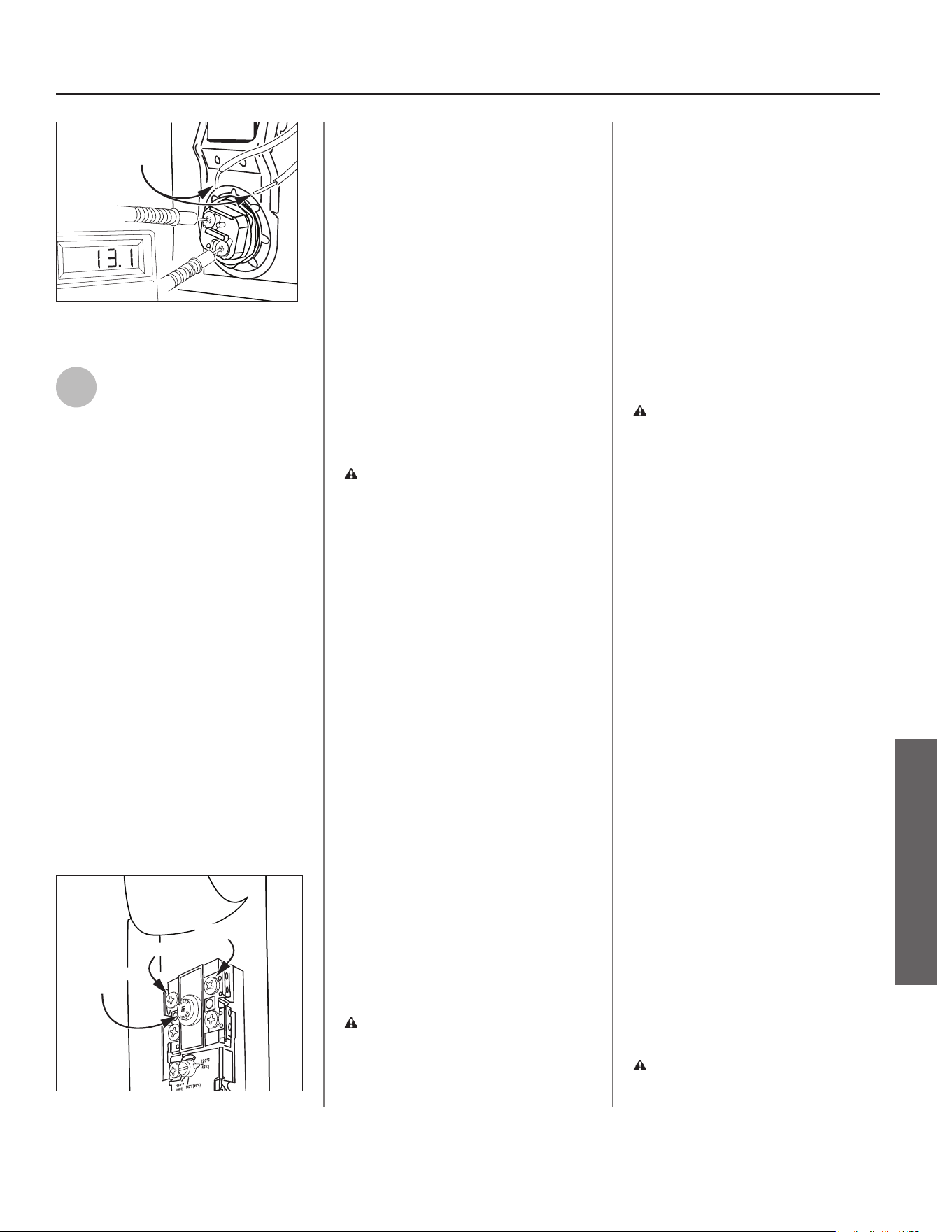
Residen al Electric Water Heater Use and Care Guide • 29
TROUBLESHOOTING
TROUBLESHOOTING
Wires are
removed
Figure 35 - Use a multimeter to check the
resistance of the upper heating element.
4
Check the Resistance of the
Upper Hea ng Element Using
a Mul meter.
Measure the resistance between the
two screw terminals on the upper
hea ng element. A good element will
have a resistance ranging between 5
and 25 Ohms. If the resistance is:
Outside this Range. Replace the
element (see “Replacing the Hea ng
Element” on page 34). If the lower
element is a concern, repeat the
element check procedure for the
lower element. The upper and lower
elements should have the same
resistance range.
Within this Range. Rea ach the power
wires, making sure the wires are in
good condi on and the connec ons
are clean and ght.
Check/Reset Energy Cut Off (ECO)
Bu on.
Terminal 1
Terminal 3
ECO Reset
Button
Figure 36 - Energy Cut Off (ECO) Button.
The Energy Cut Off (ECO) shuts off
power to the water heater’s elements
if the temperature of the water in
the tank gets too hot. If the ECO has
tripped, you will have no hot water.
A tripped ECO can usually be reset,
but you should have a qualifi ed
person inves gate the cause of the
overhea ng and repair the problem.
Do not turn the power back on un l
the cause of the overhea ng has been
iden fi ed and repaired.
To Check the Energy Cut Off (ECO):
• Turn OFF the power to the water
heater.
WARNING! Working near an
energized circuit can result in severe
injury or death from electrical shock.
Check power wires in the electrical
junc on box with a non-contact
circuit tester to make sure power is
OFF.
• Press the red ECO reset bu on
(Figure 36).
• The ECO was tripped if you hear a
click when it is reset. In most cases,
a tripped ECO indicates that the tank
overheated due to a problem with
one of the elements. Have a qualifi ed
person check the upper and lower
elements and replace if necessary.
• The ECO was not tripped if you did
not hear a click. In that case it should
be checked by a qualifi ed person.
• Replace the insula on and the upper
access panel.
• Turn the power back ON to the water
heater.
WARNING! Be sure all covers are
secured to reduce the risk of fi re and
electric shock.
Drips from T&P Relief
Valve Discharge Pipe
A small amount of water dripping from
the Temperature and Pressure (T&P)
Relief Valve usually means the home’s
water pressure is too high or you
need a properly sized and pressurized
Thermal Expansion Tank (see “Step
1” on page 7 for more informa on).
A large amount of hot water coming
from the T&P discharge pipe may be
due to the tank overhea ng.
WARNING! Do not cap or plug the
T&P Relief Valve or discharge pipe,
and do not operate the water heater
without a func oning T&P Relief
Valve - this could cause an explosion.
Water Pressure too High. High
water pressure can cause the T&P
Relief Valve to drip. Install a Pressure
Reducing Valve (PRV) on the main cold
water supply line. Adjust the PRV to
between 50-60 psi/345-414 kpa.
Thermal Expansion Tank. Install a
Thermal Expansion Tank. If a Thermal
Expansion Tank is already installed
and the T&P Relief Valve discharge
pipe drips, the Thermal Expansion
Tank may be pressurized to the wrong
pressure or the internal bladder may
be defec ve. Refer to the instruc ons
that came with the Thermal Expansion
Tank for more informa on.
Debris. In rare cases, debris can s ck
inside the T&P Relief Valve preven ng
the valve from sea ng fully. In that
case, the T&P Relief Valve discharge
pipe will drip. You may be able to clear
debris from the T&P Relief Valve by
manually opera ng the valve, allowing
small quan es of water to fl ush out
the debris. See the label on the T&P
Relief Valve for instruc ons.
WARNING! When manually
opera ng the T&P Relief Valve,
make sure that no one is in front
30 • Residen al Electric Water Heater Use and Care Guide
TROUBLESHOOTING
TROUBLESHOOTING
of or around the discharge outlet.
The water may be extremely hot
and could cause severe burns. Also,
ensure that the water discharge will
not cause property damage.
If the water pressure is between
50-60 psi/345-414 kpa, a Thermal
Expansion Tank is installed and
properly pressurized, the valve has
been cleared of any debris, and it s ll
drips, the valve may be broken – have
a qualifi ed person replace the T&P
Relief Valve.
Water Odor
Harmless bacteria normally present
in tap water can mul ply in water
heaters and give off a “ro en egg”
smell. A higher tank temperature
se ng of 140°F/60°C kills the bacteria
that causes “smelly water” and can
reduce the levels of bacteria that
cause water-borne disease. A properly
adjusted Thermosta c Mixing Valve
should be installed at each point of
use.
NOTICE: To protect the tank, an anode
rod must be installed in the water
heater at all mes or the warranty is
void.
WARNING! Because higher
temperatures increase the risk of
scalding, if the temperature set
point is higher than 120°F/49°C,
Thermosta c Mixing Valves are
par cularly important (see page 4
and Figure 8).
Water Heater Sounds
During the normal opera on of the
water heater, sounds or noises may be
heard. These noises are common and
may result from the following:
• Normal expansion and contrac on
of metal parts during periods of
heat-up and cool-down.
• Sediment buildup on or around
the elements could create varying
amounts of noise and may cause
premature tank failure. Drain and
fl ush the tank as directed (see
“Draining and Flushing the Water
Heater” on page 32).
• The heat pump compressor or fan
running.
Temperature Too High
If the water temperature is too hot:
• Adjust the Control Assembly on
the water heater (see “Adjus ng
the Control Assembly’s Opera onal
Modes” on page 21).
• Install or adjust a Thermosta c
Mixing Valve (see manufacturer’s
instruc ons).
A non-func oning thermostat or
a shorted hea ng element can
cause extremely hot water. If the
Temperature and Pressure (T&P)
Relief Valve releases large amounts
of very hot water, it is likely due to a
shortened hea ng element, or more
rarely a non-func oning thermostat,
or the thermostat does not fi t
snuggly against the tank. Very high
water temperatures can also cause
the Energy Cut Off (ECO) to trip (see
“Replacing the ECO” on page 35).
Turn power OFF un l this problem is
repaired.
Low Water Pressure
Check both the cold and hot water
at a sink to determine if the lower
pressure is only on the hot water side.
If both hot and cold faucets have low
pressure, call your local water u lity.
If the low pressure is only on the hot
water side, the primary causes of this
are:
• Melted PEX liner. Soldering copper
pipes while they are connected
to the water heater can melt the
PEX liner inside of the hot and cold
water connec ons. Mel ng the PEX
liner can restrict the fl ow of hot
and cold water. If that is the case,
replace the nipples at the hot and
cold water connec ons.
• Par ally closed supply valve. Open
the water heater’s supply valve fully.
Insuffi cient or No Hot
Water, or Slow Hot
Water Recovery
WARNING! Because higher
temperatures increase the risk of
scalding, if the temperature set
point is higher than 120°F/49°C,
Thermosta c Mixing Valves are
par cularly important (see page 4
and Figure 8).
If the hot water is simply not warm
enough, there are several possible
causes:
• Thermosta c Mixing Valve faulty or
set too low.
• Temperature set point too low.
• Hot water usage pa ern exceeds
the capability of the water heater in
current mode (see “Opera ng Mode
Descrip ons” on page 19).
• Water connec ons to unit are
reversed (disconnect and re-install
correctly).
• Leak in plumbing system (check
home for any leaks and repair).
• Lower hea ng element not
func oning properly.
• No power to the water heater (no
lights on the unit are on and display
is blank).
• Unit is in Vaca on Mode.
• ECO tripped.
Residen al Electric Water Heater Use and Care Guide • 31
TROUBLESHOOTING
TROUBLESHOOTING
• Non-func oning upper thermistor
sensor (refer to code 003 in the
“Diagnos c Codes” sec on on page
25).
• Air fi lter is dirty (see “Air Filter
Maintenance” on page 37).
• Out of posi on outlet j-tube. Assure
orienta on of line on tube is in top
posi on (side connec ons only).
Thermosta c Mixing Valves. If the
hot water is simply not warm enough,
make sure the faucet you are checking
does not have a defec ve Thermosta c
Mixing Valve. If these devices fail,
they can reduce the amount of hot
water the shower or faucet delivers
even though there is plenty of hot
water in the tank. Always check the
water temperature at several faucets
to make sure the problem is not in a
faucet or shower control.
Temperature Set Point Too Low. If the
water temperature at several faucets
is too cool, adjust the set point at
the Control Assembly (see “Water
Temperature Adjustment” on page 21).
Undersized Water Heater. If your
water heater runs out of hot water
too quickly, it may be too small for
your needs. If the water heater is old,
consider replacing it with a larger
model. If the water heater is in good
condi on, you may be able to meet
your family’s hot water needs with
the exis ng water heater by installing
a Thermosta c Mixing Valve and then
se ng the temperature to a higher
set point on the Control Assembly (see
“Water Temperature Adjustment” on
page 21).
You can also reduce your home’s hot
water needs by washing clothes in cold
water, installing fl ow restrictors on
shower heads, repairing leaky faucets,
and taking other conserva ve steps.
Reversed Connec ons or Melted
J-tube. Check the hot and cold
connec ons and make sure your
home’s hot water pipe is connected
to the hot water outlet on the water
heater. Usually, reversed connec ons
are found soon a er the installa on
of a new unit. If copper pipes were
soldered while they were a ached
to the water heater, the J-tube may
have melted. The J-tube is a curved
plas c tube inside the tank a ached to
the cold water inlet. If the J-tube has
melted, it can be replaced by removing
the old J-tube and installing a new one.
Plumbing Leak. Even a small leak
in the hot water side of the home’s
plumbing system can make it appear
that the water heater is producing
li le or no hot water. Locate and repair
the leak.
Lower Hea ng Element Not Working.
If the lower hea ng element is not
working, you will have some hot water
but not as much as before. Because
the lower element does most of the
work, it usually wears out before the
upper element. Replace the lower
element if necessary (see “Replacing
the Hea ng Element” on page 34).
Power Cycling the Unit
1
Find and turn OFF the water
heater’s circuit breaker or
remove disconnects.
2
Locate the electrical junc on
box on side of water heater,
remove cover and iden fy the
two (2) power wires.
3
Turn circuit breaker back ON
(or re-install the disconnects)
and check for power on both
incoming power wires using a
mul meter.
4
Again, turn OFF the water
heater’s circuit breaker, or
remove the disconnects and
replace the electrical junc on box
cover, before performing maintenance
work.
NOTICE: When powered on, the unit
will start to run a system diagnos c.
The diagnos c sequence typically takes
seven (7) to ten (10) minutes. During
this period the Control Assembly will
display a series of single, alterna ng
dashes repe vely.
WARNING! Working near an
energized circuit can result in severe
injury or death from electrical shock.
WARNING! When you are fi nished,
be sure all covers are secured to
reduce the risk of fi re and electric
shock.
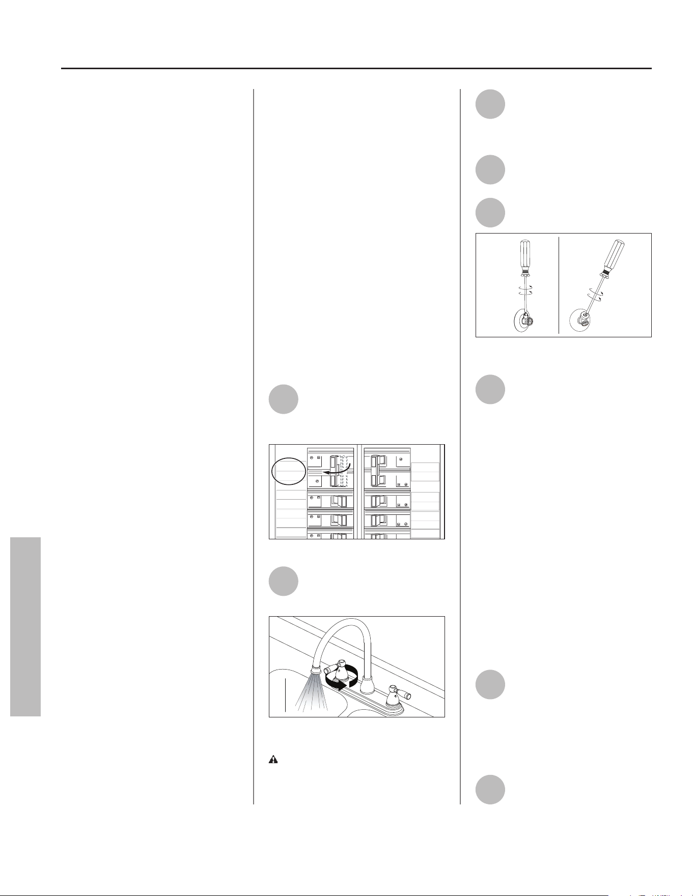
32 • Residen al Electric Water Heater Use and Care Guide
MAINTENANCE
Rou ne Maintenance
Rou ne maintenance will help your
water heater last longer and work
be er. If you cannot perform these
rou ne maintenance tasks yourself,
contact a qualifi ed person.
IMPORTANT! Failure to perform
required or recommended
maintenance as described in the
following sections may void the
warranty.
Water Heater
Maintenance
A er the fi rst six months, drain and
fl ush the water heater and inspect
the anode rod. Depending on the
hardness of your water, repeat this
process at least annually, or more
frequently if needed. From me
to me you may need to replace a
hea ng element or a thermostat.
All three maintenance tasks are
described below.
Draining and Flushing
the Water Heater
Tap water contains minerals that
can form lime deposits on hea ng
elements or sediment in the bo om
of the tank. The amount of lime
deposits or sediment depends on the
hardness of your tap water. The rate
at which sediment builds up depends
on water quality and hardness in
your area, the temperature se ngs,
and other variables. We recommend
draining and fl ushing the water heater
a er the fi rst six months of opera on
to determine the amount of sediment
buildup. Draining sediment extends
the life of the tank, hea ng elements,
and drain valves.
IMPORTANT! Failure to drain and
flush the water heater of sediment
can deteriorate the tank, heating
elements, and drain valve and cause
leaks resulting in property damage.
• In areas with very hard water,
remove and check the hea ng ele-
ments whenever you drain the tank.
If you have heavy lime deposits on
hea ng elements, you will need to
replace them more o en.
• Sediment may form large masses
that can prevent the tank from
draining. Have a qualifi ed person
use a deliming agent suitable for po-
table water to remove the sediment
buildup.
• In most cases, it is easier and less
expensive to replace lime-encrust-
ed elements than trying to remove
heavy lime deposits.
To Drain and Flush the
Tank
1
Locate the water heater’s
circuit breaker and turn it
OFF (or remove the circuit’s
fuses).
WATER
HEATER
MICRO-
WAVE
LIVING
ROOM
50
50
1
RANGE
STOVE
2
20 20
1
2015
0
FRIDGE
DISH
WASHER
HALL
LIGHTS
LAUNDRY
TYPE HOM
SERIES 1
10 kA
120/240 V-
TYPE HOM
SERIES 1
10 kA
120/240 V-
TYPE HOM
SERIES 1
10 kA
120/240 V-
TY
P
SE
R
10
k
12
0
TYPE HOM
SERIES 1
10 kA
120/240 V-
TYPE HOM
SERIES 1
10 kA
120/240 V-
TYPE HOM
SERIES 1
10 kA
120/240 V-
P
E HOM
R
IES 1
k
A
0
/240 V-
30
30
30
30
Figure 37 - Circuit Breaker.
2
Open a hot water faucet and
let the hot water run un l it
is cool.
Figure 38 - Hot Water Faucet.
WARNING! Be sure the water
runs cool before draining the tank to
reduce the risk of scalding.
3
Connect a garden hose to the
drain valve and place the
other end of the hose in a
drain, outside, or in buckets.
4
Turn the cold water supply
valve OFF.
5
Open the drain valve on the
water heater.
Figure 39 - Open Drain Valve.
6
Open a hot water faucet to
help the water in the tank
drain faster.
NOTICE: DO NOT turn electrical
power back on unless the tank is
completely full of water. This is an
addi onal precau on to protect the
elements against dry fi re. Dry fi re
occurs when power is supplied to the
electric elements without suffi cient
water in the heater. Dry fi ring the
unit will result in immediate failure
of the element. While this unit is
equipped with dry fi re protec on, the
recommended prac ce is to ensure
the tank is fi lled with water prior
to supplying power to the unit. For
complete instruc ons on fi lling the
tank, follow “Step 13” on page 16 in
the installa on sec on of this manual.
7
If sediment was present
when the tank was drained,
fl ush the tank by opening the
cold water supply valve and le ng
the water run un l no more sediment
drains from the tank. Close the drain
valve when you are done.
8
Refi ll the tank by opening the
cold water supply valve.
MAINTENANCE
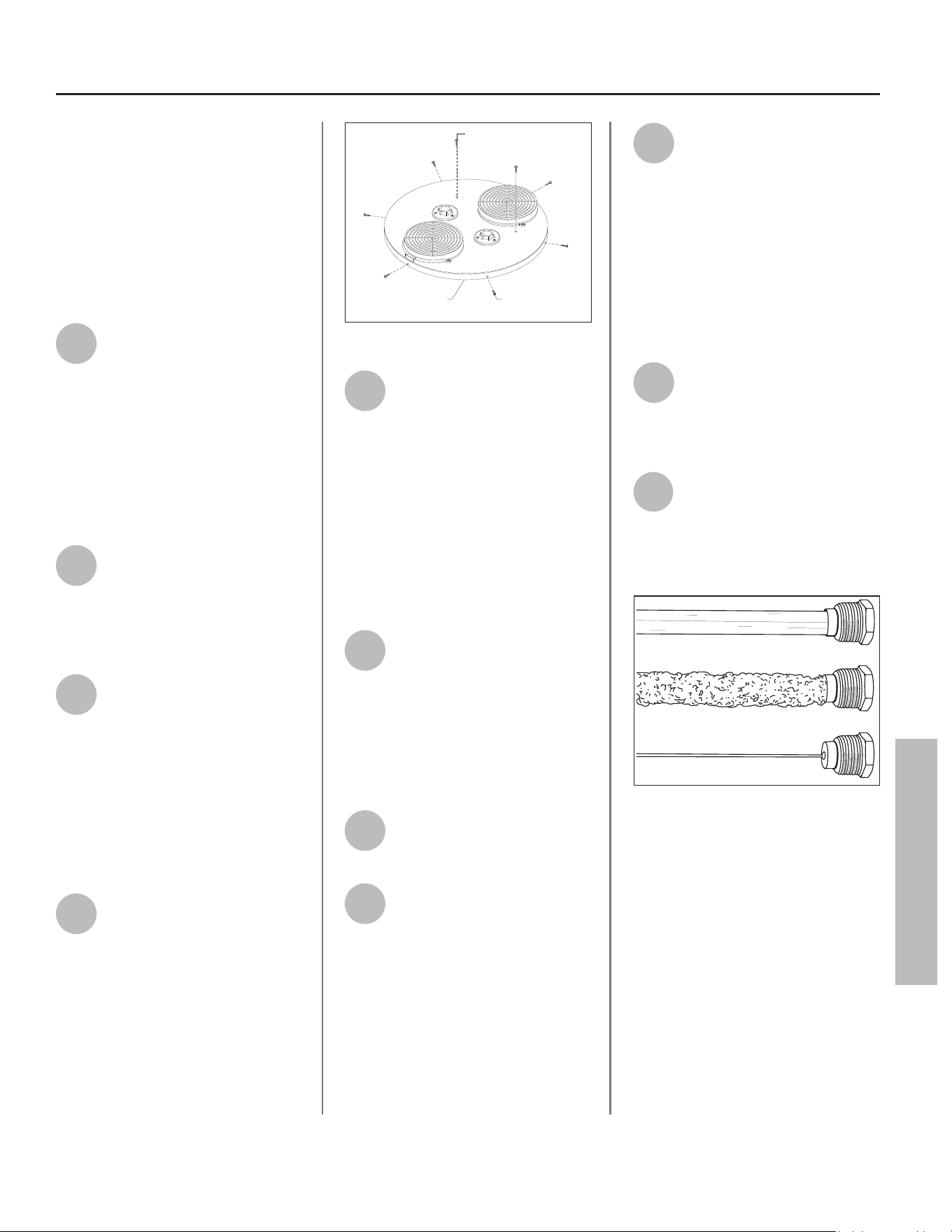
Residen al Electric Water Heater Use and Care Guide • 33
MAINTENANCE
MAINTENANCE
Make sure a hot water faucet is open
and the drain valve is closed. Allow the
hot water to run full for at least three
minutes to make sure the tank has all
the air removed and is completely full
of water. Failure to perform this step
can cause the upper hea ng element
to burn out. Once you are certain the
tank is completely full of water, close
the hot water faucet.
9
Turn ON power to the water
heater at the circuit breaker/
fuse box. It may take two
hours for the tank to heat up.
Replacing the Anode
Rod
NOTICE: The Control Assembly will
display error code 044 when the anode
rod has been depleted.
1
To replace the anode rod if it
is depleted: Turn the power
OFF. Run hot water un l it is
cool. Turn cold water supply valve OFF.
Open a hot water faucet to
depressurize tank.
2
Remove duc ng from unit.
Disconnect cold water supply
and hot water supply
connec ons from top of unit if
necessary to remove jacket cover.
To avoid damaging gaskets in the fl ex
lines, use a pipe wrench at the hot
and cold nipples to counter torque
when installing or removing water
connec ons. DO NOT over ghten.
3
Remove the six (6) screws
located around the perimeter
of the jacket cover. Locate and
remove the two (2) screws on top of
the unit fastening the jacket cover to
the heat pump evaporator. Li the
jacket cover up and away from the unit
to gain access to the anode rod (see
illustra on on back cover for loca on
of anode rod).
Perimeter
Screw (6x)
Evaporator
Screw (2x)
Shroud Cover
Figure 40 - Remove Shroud Cover
4
Once the anode rod is
exposed, remove the top nut
with a 10 mm hex socket
wrench and remove the wire terminal
(do not remove lower hex nut from
bolt). With the wire terminal removed,
use a 1-1/16” socket wrench with an
extension to remove the anode rod.
Inspect the anode rod and replace if
depleted. Apply thread sealant tape or
pipe joint compound and reinstall the
anode rod ghtly. Connect the wire
terminal and secure with hex nut.
5
Install jacket cover to water
heater by following the
instruc ons outlined in Step 3
in reverse order.
NOTICE: Flex hose connec ons must
be aligned with nut retainers to install
shroud cover to shroud. Adjust fl ex
hoses accordingly.
6
Reconnect cold water supply
and hot water supply
connec ons at top of unit.
7
Refi ll the tank by opening the
cold water supply valve. Make
sure a hot water faucet is
open and the drain valve is closed.
Allow the hot water to run full for at
least three (3) minutes to make sure
the tank has all the air removed and is
completely full of water. Failure to
perform this step can cause the upper
hea ng element to burn out. Once you
are certain the tank is completely full
of water, close the hot water faucet.
8
Remove the three (3) screws
securing intake duct adaptor
(closest to front side of water
heater) to jacket cover. Li intake duct
adaptor up and away from jacket cover
to visually inspect for leaks around the
anode fi ng and water connec ons. If
there are no leaks, proceed to Step 9.
If there is a leak, turn OFF water supply
to the water heater, open a faucet to
eliminate pressure, and ghten the
anode rod further. Return to Step 7.
9
Install intake duct adaptor to
jacket cover and secure with
three (3) screws. Reconnect
any duc ng to the intake and exhaust
adaptors.
10
Reconnect power to the water
heater. It may take several
hours for the tank to heat up
depending on the tank size,
temperature se ng, and cold water
supply temperature.
Figure 41 - Anode Rods from new (top) to
partially depleted (middle) to fully depleted
stages (bottom).
Anode Rod. The anode rod is a
sacrificial metal rod and is the water
heater’s first line of defense to prevent
corrosion and premature failure
(leaks) in the tank. The anode rod
is a consumable item. Inspect the
anode rod a er the fi rst six months of
opera on when you drain and fl ush
the tank. Replace the anode rod if it
is substan ally worn out or depleted.
Therea er, inspect the anode rod
annually or more frequently if needed.
If you use a water so ener, your
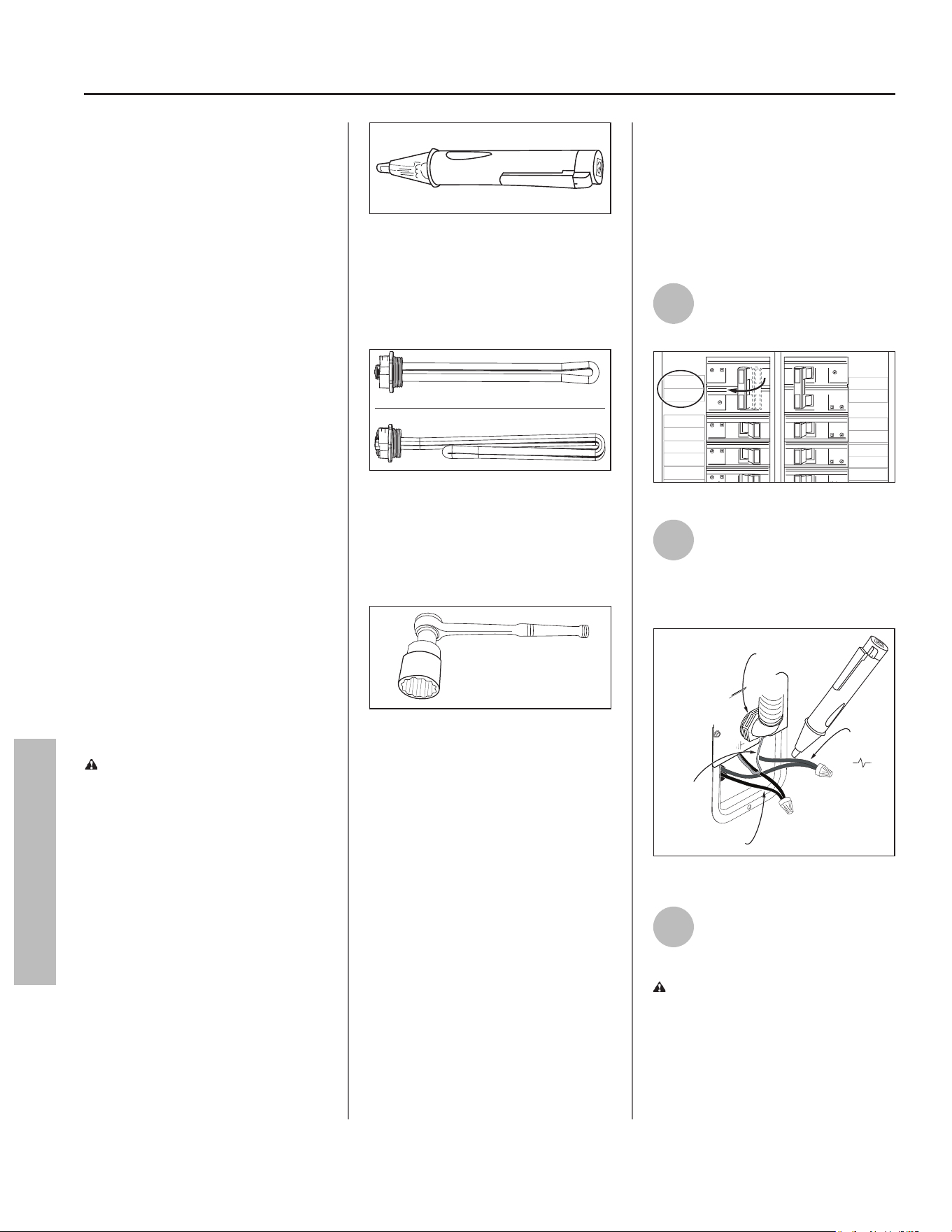
34 • Residen al Electric Water Heater Use and Care Guide
MAINTENANCE
MAINTENANCE
anode rod will deplete faster than
normal. Inspect the anode rod more
frequently, replacing the anode rod as
needed. Obtain new anode rods from
your local plumbing supplier or have
a qualifi ed person replace it (anode
rods are a consumable item and are
not covered under warranty).
Cleaning the Hea ng
Element
At least annually, inspect upper and
lower elements for scaling or damage
caused by corrosive water condi ons
and mineral deposits. If elements
show scaling or damage they MUST
be replaced.
Follow the instruc ons in the next
sec on to disconnect power to the
water heater and drain the tank
before accessing the elements.
IMPORTANT! Failure to replace
elements showing scaling can lead
to corrosion and premature failure
of the element causing water to
leak through. Replacing the heating
elements is necessary.
Replacing the Hea ng
Element
WARNING! Working near an
energized circuit can result in severe
injury or death from electrical
shock. Turn power OFF. Check wires
with a non-contact circuit tester to
make sure power is OFF. When you
are fi nished, be sure all covers are
secured to reduce the risk of fi re and
electric shock.
If you are not comfortable replacing
a hea ng element or thermostat
yourself, have this work done by
a qualifi ed person. To replace the
hea ng element, you will need the
following tools and supplies:
ON
OFF
Figure 42 - Non-Contact Circuit Tester.
• Always turn power OFF and check
the power wires with a non-contact
circuit tester before working on the
water heater.
Figure 43 - Heating Element (with gasket).
• Check your water heater’s data plate
for the correct wa age and voltage.
Hea ng elements are available at
your local plumbing supplier.
Figure 44 - Element Wrench.
• Some regular sockets (1-1/2 inch)
may work, but regular sockets
are o en beveled and may slip.
Inexpensive element wrenches are
available at your local plumbing
supplier.
• Garden hose to drain the tank.
• Hand dishwashing liquid to lubricate
the gasket.
• A clean cloth to clean the threaded
opening.
• A fl at blade and Phillips screwdriver.
Steps for Replacing the
Hea ng Element:
NOTICE: A diagnos c code (see
“Control Assembly Diagnos c Code
Chart” on page 25) should indicate if
the upper or lower element has failed.
1
Turn the power OFF at the
circuit breaker or remove
fuses.
WATER
HEATER
MICRO-
WAVE
LIVING
ROOM
50
50
1
RANGE
STOVE
2
20 20
1
2015
0
FRIDGE
DISH
WASHER
HALL
LIGHTS
LAUNDRY
TYPE HOM
SERIES 1
10 kA
120/240 V-
TYPE HOM
SERIES 1
10 kA
120/240 V-
TYPE HOM
SERIES 1
10 kA
120/240 V-
TY
P
SE
R
10
k
12
0
TYPE HOM
SERIES 1
10 kA
120/240 V-
TYPE HOM
SERIES 1
10 kA
120/240 V-
TYPE HOM
SERIES 1
10 kA
120/240 V-
P
E HOM
R
IES 1
k
A
0
/240 V-
30
30
30
30
Figure 45 - Circuit Breaker.
2
Open the electrical junc on
box on the side of the water
heater. Using a non-contact
circuit tester, check the power wires
to make certain the power is OFF.
ON
OFF
Ground
Wires
1/2" Conduit
Connection
Black Wires
Red
Wires
Figure 46 - Non-Contact Circuit Tester.
3
Open a hot water faucet and
let the hot water run un l it
is cool.
WARNING! Be sure the water
runs cool before draining the tank to
reduce the risk of scalding.
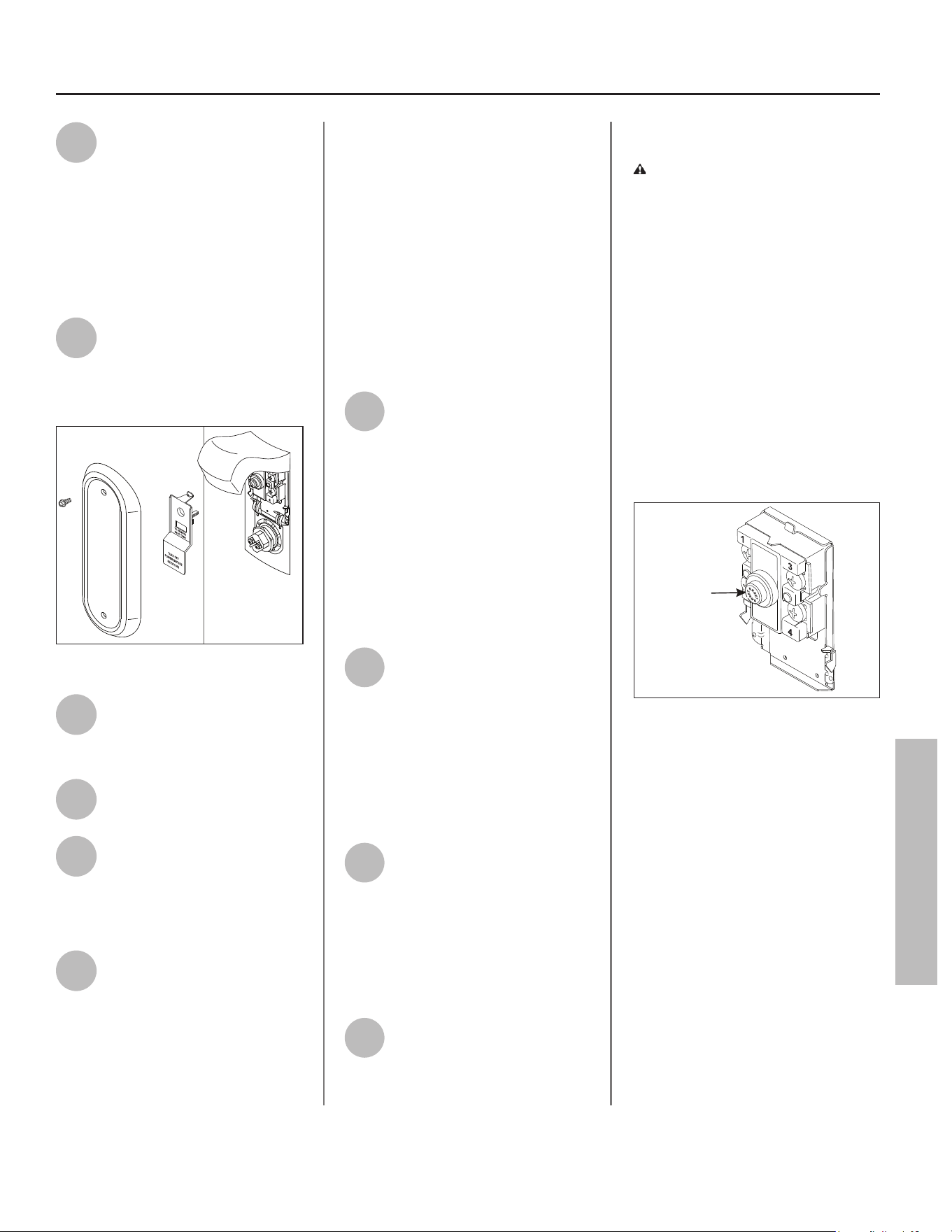
Residen al Electric Water Heater Use and Care Guide • 35
MAINTENANCE
MAINTENANCE
4
Connect a garden hose to the
drain valve and place the
other end of the hose in a
drain or outside (or use buckets). Turn
OFF the cold water valve that supplies
the water heater. Open the drain valve
on the water heater. Opening a hot
water faucet will help the tank drain
faster.
5
Remove the upper or lower
access panel on the water
heater, and then fold back the
insula on and remove the plas c
element/thermostat cover.
Figure 47 - Access Panel.
6
With the tank drained and the
power OFF, remove the
power wires from the element
you intend to replace.
7
Remove the bad element
using an element wrench.
8
Make sure the new element is
the correct replacement by
referring to the water heater’s
data plate for voltage and wa age
informa on.
9
Clean the threads in the tank
opening with a rag. Insert the
new element equipped with a
rubber gasket. Use a drop of hand
dishwashing liquid to lubricate the
gasket to help avoid damaging the
gasket as it is being ghtened. Tighten
with an element wrench.
IMPORTANT! A new gasket MUST be
installed with a new element. Failure
to install a new gasket could lead to
premature failure of the element
causing water to leak through resulting
in property damage.
NOTICE: DO NOT turn power back
on un l the tank is completely full of
water. For complete instruc ons on
fi lling the tank, follow “Step 13” on
page 16 in the installa on sec on of
this manual.
10
Refi ll the tank by opening the
cold water supply valve. Make
sure a hot water faucet is
open and the drain valve is closed.
Allow hot water to run full for at least
three (3) minutes to make sure the
tank has all the air removed and is
completely full of water. Failure to
perform this step can cause the upper
hea ng element to burn out. Once you
are certain the tank is completely full
of water, close the hot water faucet.
11
Check the newly installed
element for leaks. If a leak is
present, ghten the element
un l the leak stops. If you cannot stop
the leak, drain the tank and remove
the element. Inspect the gasket for
damage. If the gasket is damaged,
replace the gasket and reinstall the
element.
12
Once the element is
successfully installed and
there are no leaks, replace the
power wires, thermostat cover,
insula on, and access panel. Make
sure all wire connec ons are ght.
Replace the cover on the electrical
junc on box.
13
Turn ON power to the water
heater at the circuit breaker/
fuse box. It may take two
hours for the tank to heat up.
Replacing the ECO
WARNING! Working near an
energized circuit can result in severe
injury or death from electrical
shock. Turn power OFF. Check wires
with a non-contact circuit tester to
make sure power is OFF. When you
are fi nished, be sure all covers are
secured to reduce the risk of fi re and
electric shock.
To replace the ECO, you will need the
following tools and supplies:
• A non-contact circuit tester. Always
turn power OFF and check with a
non-contact circuit tester before
working on the water heater.
ECO Reset
Button
Figure 48 - ECO
• A replacement ECO (see the repair
parts list on back cover).
• A business card to check the gap
between the ECO and tank.
• Tape and a permanent marker to
mark the wires.
• A fl at blade and Phillips screwdriver
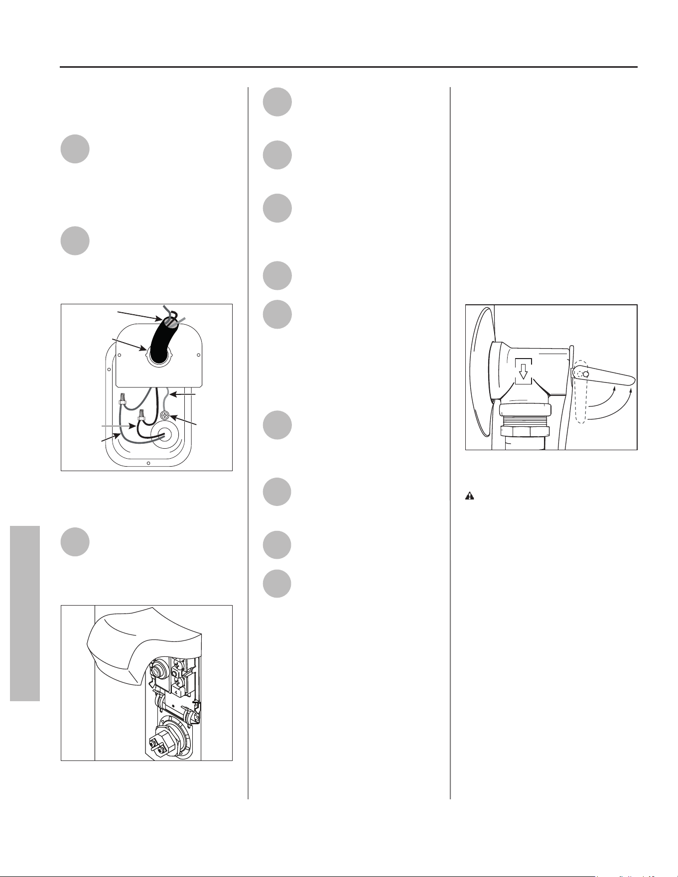
36 • Residen al Electric Water Heater Use and Care Guide
MAINTENANCE
MAINTENANCE
Steps for Replacing the
ECO:
1
Turn the power OFF at the
circuit breaker or remove
fuses.
NOTICE: It is not necessary to drain
the tank to replace an ECO.
2
Open the electrical junc on
box on the side of the water
heater. Using a non-contact
circuit tester, check the power wires
to make certain the power is OFF.
1/2” Conduit
Opening
Green
Ground
Screw
Green
Ground
Wire
Red Wire
Black Wire
Power Supply
Connector
Figure 49 - Electrical Junction Box (bottom
cover to electrical junction box removed for
clarity).
3
Remove the upper access
panel on the water heater
and carefully fold back the
insula on and plas c element/ECO
cover (Figure 50).
Figure 50 - Element Access Panel/ECO
Compartment.
4
Make sure the replacement
ECO matches the original
ECO.
5
Mark the wires with tape so
you will know how to put
them back on.
6
Disconnect the wires from
the bad ECO and remove the
ECO from the metal
moun ng clip.
7
Install the new ECO in the
metal moun ng clip.
8
Make sure the new ECO fi ts
snuggly against the tank. You
should NOT be able to slip a
business card between the ECO and
the tank. If you can, bend the ECO
moun ng clip un l the ECO fi ts ghtly
against the tank.
9
A ach the wires following
the wiring diagram on the
water heater’s label. Make
sure all wire connec ons are ght.
10
Replace the plas c element/
ECO cover, insula on, and
access panel.
11
Replace the cover on the
electrical junc on box.
12
Turn ON power to the water
heater at the circuit breaker/
fuse box.
T&P Relief Valve
Maintenance
Read and follow the opera ng and
annual maintenance instruc ons
provided by the manufacturer of
the T&P Relief Valve (yellow label
a ached to the T&P Relief Valve).
If no label is a ached to the T&P
Relief Valve, follow the instruc ons
in this sec on. Minerals in the
water can form deposits that cause
the valve to s ck or create blocked
passages, making the T&P Relief Valve
inopera ve. Follow these guidelines:
• At least annually, inspect the T&P
Relief Valve and discharge pipe for
damage caused by corrosive water
conditions and mineral deposits.
Operate the T&P Relief Valve
manually to ensure the waterways
are clear and the valve mechanism
moves freely (below). Before
operating the valve manually, check
that it will discharge in a place for
secure disposal.
Figure 51 - T&P Relief Valve.
WARNING! Hot water will be
released. Before opera ng the T&P
Relief Valve manually, check that it
will discharge in a safe place. If water
does not fl ow freely from the end of
the discharge pipe, turn the power to
the water heater OFF. Call a qualifi ed
person to determine the cause.
• Note that a dripping T&P Relief Valve
is usually caused by the home’s
water pressure being too high or
the lack of a Thermal Expansion
Tank. If your T&P Relief Valve drips,
see “Drips from T&P Relief Valve
Discharge Pipe” on page 29.
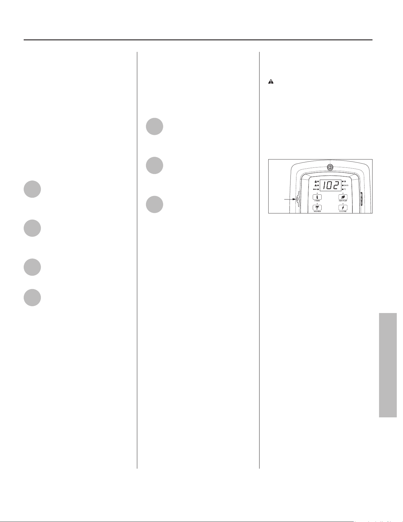
Residen al Electric Water Heater Use and Care Guide • 37
MAINTENANCE
Air Filter Maintenance
The heater will monitor the heat pump
opera on status and indicate whether
the fi lter should be cleaned. If the
Control Assembly displays the code
080, this indicates the fi lter should be
cleaned or replaced with the following
process (see exploded view of the unit
on page 39 for air fi lter loca on).
NOTICE: Before a emp ng to clean
or replace the air fi lter, turn OFF the
power to the water heater at the
circuit breaker/fuse box.
1
Take the tab on the air fi lter
and remove (slide) it from the
top facing air intake duct
adaptor.
2
To clean the fi lter, use a
vacuum with a hose
a achment to remove any
dust or debris.
3
Slide the new or cleaned fi lter
into the air intake duct
adaptor.
4
Turn ON power to the water
heater at the circuit breaker/
fuse box.
NOTICE: The water heater may
conduct a system diagnos c prior to
opera on.
Condensate Drain
Maintenance
NOTICE: Before a emp ng to clean
the condensate drain pan or lines, turn
OFF power to the water heater at the
circuit breaker/fuse box.
1
Check the condensate drain
pan and drain lines for any dirt
or debris that might interfere
with proper drainage.
2
Use a pipe cleaner to clear
debris from condensate drain,
condensate line, and
condensate drain pan.
3
Once the condensate drain
pan and lines have been
inspected/cleaned, turn ON
power to the water heater at the
circuit breaker/fuse box.
NOTICE: The water heater will conduct
a system diagnos c prior to opera on.
Control Assembly
Ba ery Maintenance
CAUTION! Ba ery may explode
if mistreated. DO NOT recharge,
disassemble or dispose of in fi re.
It is recommended to replace the
ba ery in the Control Assembly every
fi ve (5) years for reliability.
Locate the ba ery tray on the le side
of the Control Assembly (Figure 52).
Battery
Tray
Figure 52 - Battery Tray location.
Replace the BR2032 or CR3032 ba ery
by removing the Phillips head screw
and sliding the ba ery tray with
ba ery out from the Control Assembly.
Insert the new Panasonic® BR2032 or
Murata CR3032 ba ery into the tray and
reinstall into the Control Assembly. Hand
ghten the Phillips head screw to secure
the tray in the Control Assembly.
NOTICE: If the Control Assembly was
not connected via Wi-Fi, Bluetooth, or
powered by a power source, the me
will need to be set.
MAINTENANCE
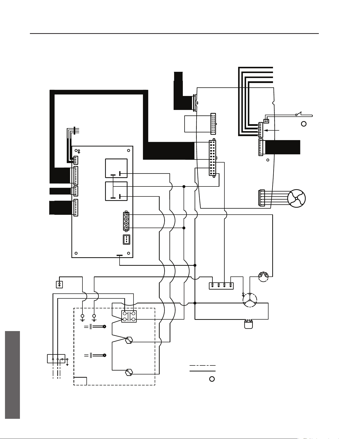
38 • Residen al Electric Water Heater Use and Care Guide
DIAGRAMS
J9
SHUT OFF VALVE
BLUE
BLACK
GREEN
YELLOW
AMBIENT TEMP. SENSOR
COIL TEMP. SENSOR
SUCTION TEMP. SENSOR
DISCHARGE TEMP. SENSOR
CONDENSATE WATER
ALARM SIGNAL
a
TO DAUGHTER
BOARD
ANODE
(OPTION OF WATER
TEMP. SENSOR AND
BYPASS VALVE FOR
PREMIUM MODEL)
FAN MOTOR
BLACK
TANK LOWER TEMP. SENSOR
RED
A-A
B-B
TANK UPPER TEMP. SENSOR
EEV
TO MAIN
CONTROL
BOARD
TANK
A-A
TANK LOWER
TEMP. SENSOR
B-B
TANK UPPER
TEMP. SENSOR
BLACK
BLACK
BLACK
RED
BLUE
WHITE
LOWER ELEMENT
4.5KW
1
2
3
4
BLACK
UPPER ELEMENT
4.5KW
HIGH LIMIT
SWITCH
MOTOR
PROTECTOR
TANK TOP
COVER
COMPRESSOR
C
R
S
CAPACITOR
OPTIONAL OVERFLOW SWITCH
NORMALLY CLOSED
a
FIELD WIRING
FACTORY WIRING
JUNCTION
BOX
L1 L2 G
BLACKRED
TANK
JACKET
GREEN
GREEN
GREEN
GREEN
GREEN
RED
WHITE
RED
BLACK
BLACK
BLACK
RED
RED
BLUE
WHITE
RED
CONDENSATE WATER
LEVEL SWITCH
9$&+]+]ĭ
9$&+]+]ĭ
Control Assembly and Thermostat Wiring Diagram
DIAGRAMS
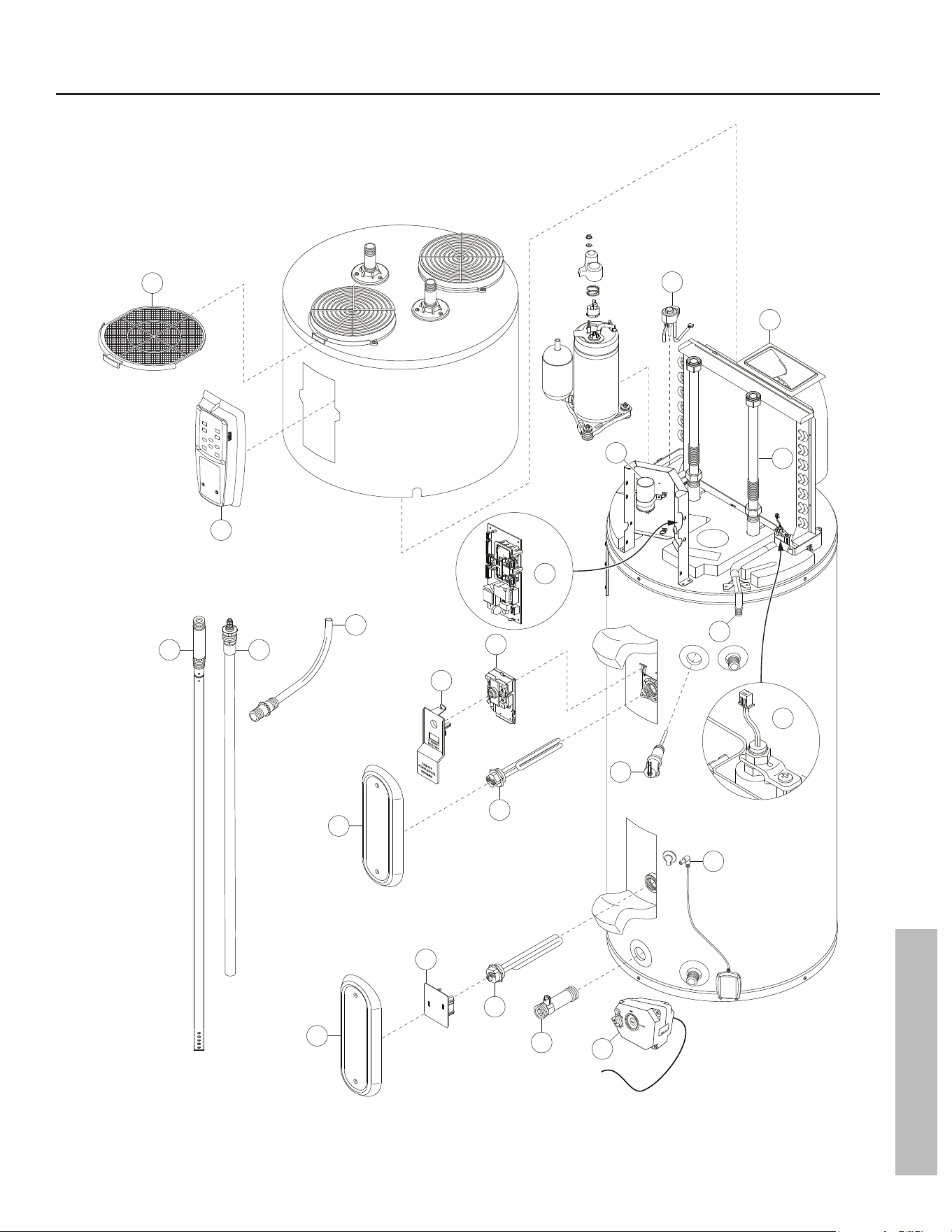
Residen al Electric Water Heater Use and Care Guide • 39
REPAIR PARTS
REPAIR PARTS
11
19
14
14
12
15
10
20
3
1
4
13
13
6
18
5
17
8 9
Quick Release
to remove valve body
21
7
2
16
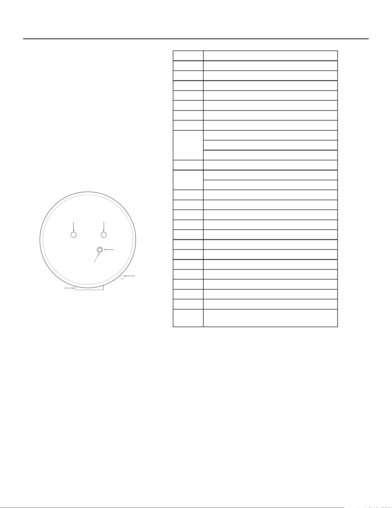
REPAIR PARTS
REPAIR PARTS
Repair parts may be ordered through your
plumber, local distributor, home improvement
center, or by calling our Technical Assistance
Hotline which is listed on your warranty. When
ordering parts, always give the following
informa on:
1. Model, serial and product number
2. Item number
3. Parts descrip on
ITEM NO. PARTS DESCRIPTION
1 Air Filter
2 Fan Motor Assembly
3 Electronic Expansion Valve Solenoid
4 Control Assembly
5 Daughter Board, 208V/240V
6 Run Capacitor
7 Flex Hoses (2x), Gaskets
8
Dip Tube, for 50 gallon
Dip Tube, for 66 gallon
Dip Tube, for 80 gallon
9 Anode Rod, 37” for all models
10
J-Tube, for 50 gallon
J-Tube, for 66 and 80 gallon
11 Upper Element Personnel Protector
12 Energy Cut-Off (ECO) Switch
13 Element Access Panel
14 Element, 4500 Wa s
15 Temperature & Pressure Relief Valve
16 Condensate Drain Valve
17 Condensate Drain Switch
18 Leak Detec on Sensor
19 Lower Element Personnel Protector
20 Drain Valve
21 Automa c Cold Water Shut-Off Valve
22 Upper / Lower Tank Thermistor Assembly*
23
Ambient / Discharge / Coil / Suc on
Temperature Sensor Assembly*
*Part not shown.
Anode
T&P Valve
Control Assembly
Front of Unit
Back of Unit
37” for all models
ColdHot
Apple logo and Apple App Store Logo are trademarks of Apple Inc.
Google Play and the Google Play Logo are trademarks of Google LLC.
Copyright © 2025, A.O. Smith. All Rights Reserved
Limited Warranty provided by Manufacturer.