
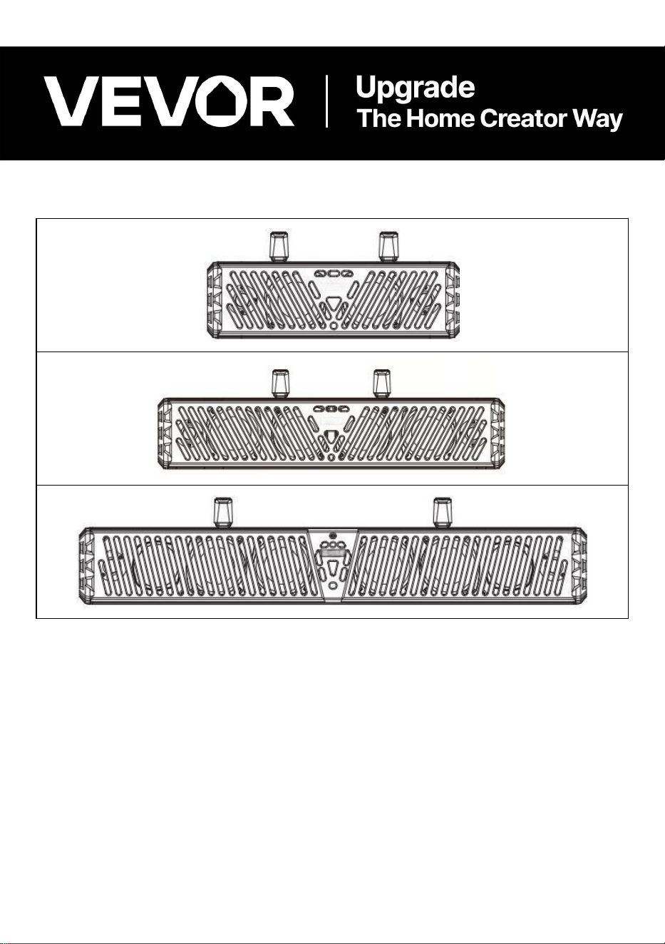
VE-401
VE-601
VE-801
VEVOR Support Center
Marine and ATV Bluetooth Speakers
MODEL: VE-401/ VE-601/ VE-801
- 1 -
Model:VE-401/VE-601/VE-801
This is the original instruction, please read all instruction manual instructions
carefully before operating. VEVOR reserves a clear interpretation of our user
instruction manual. The appearance of the product shall be subject to the product
you received. Please forgive us that we won't inform you again if there are any
technology or software updates on our product.
- 2 -
Warning-To reduce the risk of injury, user must read instructions
instruction manual carefully.
This device complies with Part 15 of the FCC Rules. Operation is
subject to the following two conditions:(1)This device may not cause
harmful interference, and (2)this device must accept any
interference received, including interference that may cause
undesired operation.
This product is subject to the provision of European Directive
2012/19/EC. The symbol showing a wheelie bin crossed through
indicates that the product requires separate refuse collection in the
European Union. This applies to the product and all accessories
marked with this symbol. Products marked as such may not be
discarded with normal domestic waste, but must be taken to a
collection point for recycling electrical and electronic devices
INSTRUCTIONS
Thank you for purchasing our products. Committed to providing customers with the
best quality products and service has always been our lifelong goal. Before using
the product, please read this instruction manual carefully to ensure correct use.
Keep the instruction manual in a place where the user can find it at any time.
SAFETY INSTRUCTIONS
Important Safety Precautions:
● Do not adjust audio settings while operating the vehicle. Safe driving and
consideration for the safety of others should always be your top priority.
● If smoke, abnormal noise, strange odor or other malfunctions occur, cut off
power supply immediately.Using the product in this situation may cause
permanent damage.
● Start at low volume and turn up gradually until audio plays clearly without

- 3 -
distortion or ear discomfort.
Please Be Sure To Follow The Following Guidelines:
● Do not raise volume to a level that blocks out surrounding ambient noise.
● In potentially dangerous environments, use with caution or stop using the
product temporarily.
Installation Precautions:
● Untrained personnel performing installation or maintenance on this product face
risks of electric shock, physical injury and other hazards.
● If you have any installation, service issues or needs, please contact customer
service.
● When directly connected to the vehicle battery, Disconnect the battery negative
wire before any wiring work. of the battery before starting any wiring operation.
Install a minimum 15A fuse and fuse holder on the battery positive wire.
● The soundbar is designed to be weather resistant and must never be submerged
underwater under any circumstances → must never be fully submerged
● Only use the installation components provided with the soundbar.
● Use mild soap or detergent, wash with warm water and a clean sponge or soft
cloth, and then rinse thoroughly with clean water.
Very Important:
● Do not clean the unit under direct hot sunlight or in high-humidity conditions.
● Do not use abrasives or highly alkaline cleaners on the main body.
● Do not use blades or other sharp tools to scratch the main body.
● These solvents will damage the plastic housing.
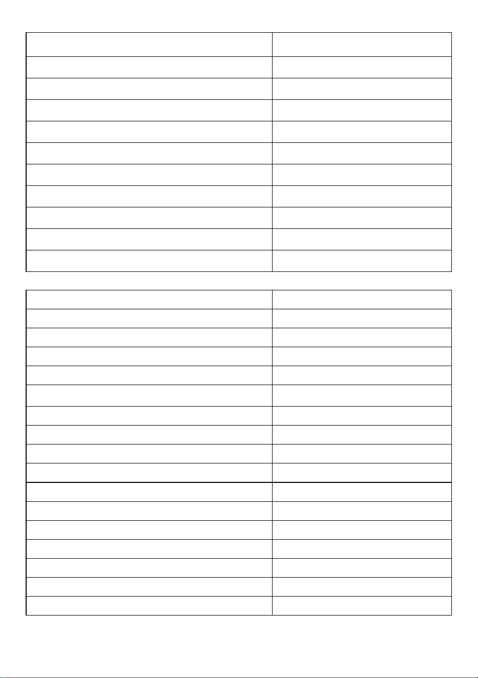
TECHNICAL SPECIFICATIONS
Model
VE-401
BT Protocol
V5.0
BT Range
33 ft / 10 m
Frequency Response
40 Hz – 22 kHz
Operating Voltage
12 V DC (8~18V allowable)
- 4 -
Max. Working Current
≤10 A
Rated Power
60 W
Tweeters
1" (×2)
Mid-woofer
4" (×2)
Wireless Remote Distance
19.7 ft / 6 m – 26.2 ft / 8 m
MP3 Signal Noise Ratio
≥50 dB
MP3 Channel Separation
≥30 dB
MP3 Total Harmonic Distortion (THD)
≤5%
MP3 Vocal Channel Balance
≤2 dB
Operating Temperature
-20 °C – 60 °C
Dust / Waterproof Rating
IP65
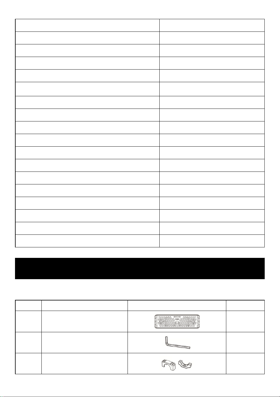
Model
VE-601
BT Protocol
V5.0
BT Range
33 ft / 10 m
Frequency Response
40 Hz – 22 kHz
Operating Voltage
12 V DC (8~18V allowable)
Max. Working Current
≤10 A
Rated Power
80 W
Tweeters
1" (×2)
Mid-woofer
4" (×2)
Low Frequency Radiator
4" (×2)
Wireless Remote Distance
19.7 ft / 6 m – 26.2 ft / 8 m
MP3 Signal Noise Ratio
≥50 dB
MP3 Channel Separation
≥30 dB
MP3 Total Harmonic Distortion (THD)
≤5%
MP3 Vocal Channel Balance
≤2 dB
Operating Temperature
-20 °C – 60 °C
Dust / Waterproof Rating
IP65
- 5 -
Model
VE-801
BT Protocol
V5.0
BT Range
33 ft / 10 m
Frequency Response
40 Hz – 22 kHz
Operating Voltage
12 V DC (8~18V allowable)
Max. Working Current
≤13 A
Rated Power
120 W
Tweeters
1" (×2)
Mid-woofer
3" (×2)
Subwoofer
4" (×2)
Low Frequency Radiator
4" (×2)
Wireless Remote Distance
19.7 ft / 6 m – 26.2 ft / 8 m
MP3 Signal Noise Ratio
≥50 dB
MP3 Channel Separation
≥30 dB
MP3 Total Harmonic Distortion (THD)
≤5%
MP3 Vocal Channel Balance
≤2 dB
Operating Temperature
-20 °C – 60 °C
Dust / Waterproof Rating
IP65
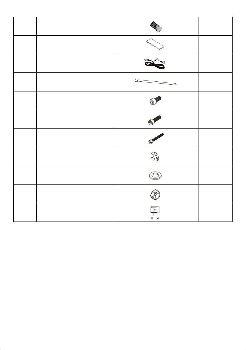
ASSEMBLY PARTS AND INSTALLATION STEPS
Assembly Parts:Model:VE-401/VE-601/VE-801
No.
Part Name
Reference Image
QTY
1
Main Unit
1
2
M5 wrench
1
3
Bracket
2
- 6 -
4
Remote control
1
5
Rubber pad
4
6
Power cord
1
7
Cable tie
10
8
Hex socket bolt(M6x18)
3
9
Hex socket bolt(M6x40)
5
10
Hex socket bolt(M6x60)
5
11
Spring washer
7
12
Flat washer
7
13
M6 Nut
5
14
Fuse
2
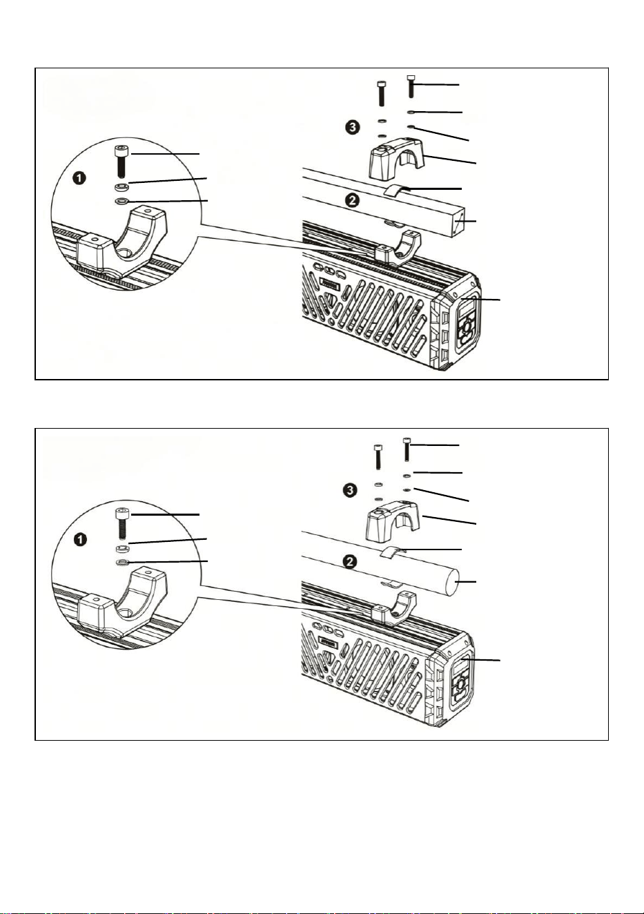
Installation Steps:
● Fix the soundbar onto the roll cage using the supplied adjustable bracket.
● Inspect all brackets before every ride.
1. Fit the mounting bracket into the slot on top of the soundbar and fasten it with a
hex screw.
2. Attach the included rubber pad for tight clamping and to prevent abrasion.
3. Tighten the upper and lower brackets with a hex wrench. Be sure to use the
supplied spring washers to secure bolts firmly and prevent loosening caused by
vibration.
4. Repeat the above steps to secure the soundbar with the second mounting
fixture.
- 7 -
A. Square Tube:
B.Round Roll Bar:
Hex socket bolt
Spring washer
Flat washer
Hex socket bolt
Spring washer
Flat washer
Upper clamp
Rubber strip
Mounting bar
1.1"– 2.1"
Lower clamp
Hex socket bolt
Spring washer
Flat washer
Hex socket bolt
Spring washer
Flat washer
Upper clamp
Rubber strip
Mounting bar
φ1.1 "- φ2.1
"
Lower clamp
- 8 -
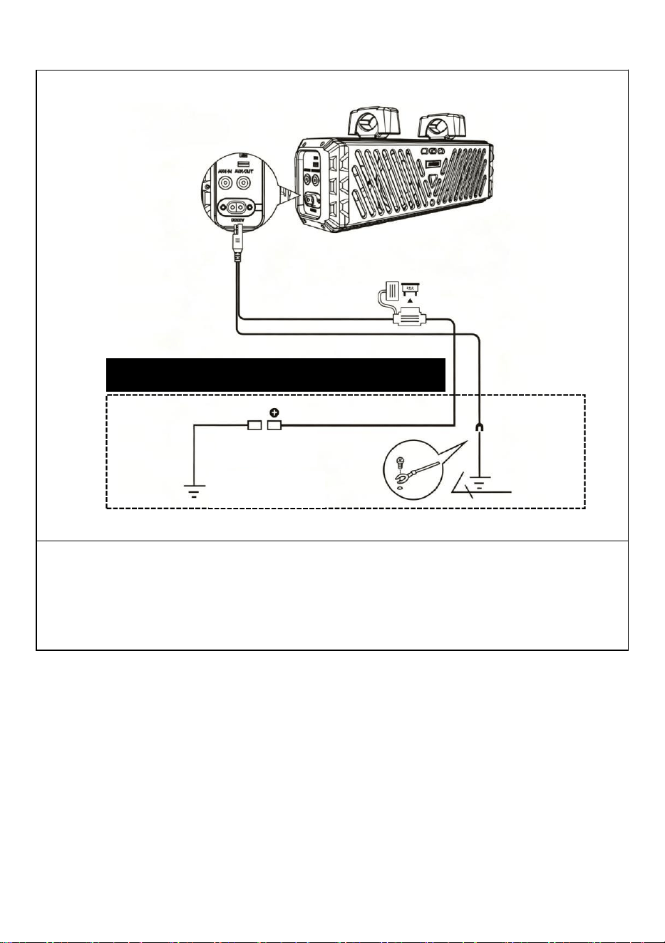
Wire Diagram:
Important Reminder: To prevent draining your vehicle battery, run the engine
during prolonged use. Operating the unit with the engine off will drain battery
power rapidly.
Power cord
15A Fuse
OPTIONAL DIRECT BATTERY WIRING CIRCUIT
RED
BLACK
Ground wire
Battery 12V
Ground wire
- 9 -
OPERATING INSTRUCTIONS
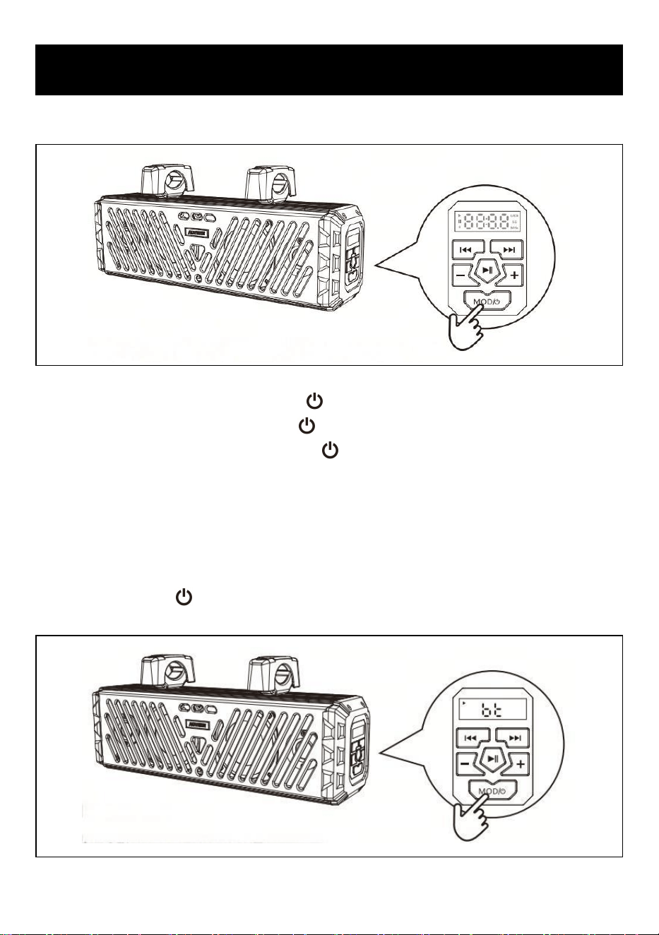
POWER ON/OFF:
1. Power On: Short-press the "MOD/ " button to power on the unit.
2. Power Off: long-press the "MOD/ " button to power off.
3. After startup, Short-press the "MOD/ " button to switch modes cyclically
among BT, USB and AUX, with corresponding voice prompts. The USB mode will
be skipped automatically if no USB flash drive is detected.
BT OPERATION:
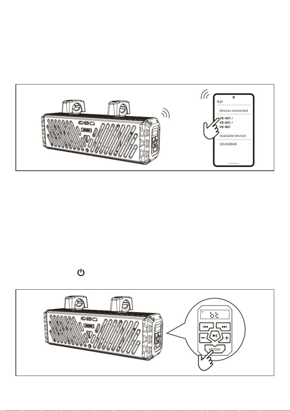
Pairing & Discovering A New BT Connection
1.Press the "MOD/ " button to switch the soundbar to BT mode and start pairing.
- 10 -
Mobile Operation
a. Enter the settings menu of your mobile device.
b. Enter the Bluetooth menu.
c. Turn on Bluetooth and start scanning.
d. VE-401 / VE-601 / VE-801 will appear under Available Devices.
e. If a passcode is required, enter either “0000” or “1234”.
2.If VE-401 / VE-601 / VE-801 does not appear, please repeat the above steps to
refresh the device list.
3.Once connected successfully, you can stream your favorite music to the
soundbar for playback.
BLUETOOTH OPERATION:
Reconnection
1.Turn on the soundbar and your previously paired Bluetooth device.
2.Press the "MOD/ " button to switch to BT mode; the device will reconnect
automatically.
- 11 -
3.If your device was previously paired with the soundbar but is not the most
recently paired device:
a.Ensure no other devices are connected at present.
a. Initiate pairing on your mobile device.
b. VE-401 / VE-601 / VE-801 will appear under Available
Devices.
d.Select VE-401 / VE-601 / VE-801 to reconnect.
4. If the device moves out of Bluetooth range, the connection will disconnect
automatically:
a. The soundbar’s "BT" indicator flashes, and a voice prompt announces "BT
Disconnected".
b.Once back within range, the soundbar will reconnect to the device automatically.
5.The Bluetooth function only supports one connected device at a time;
simultaneous multi-device pairing is not available.
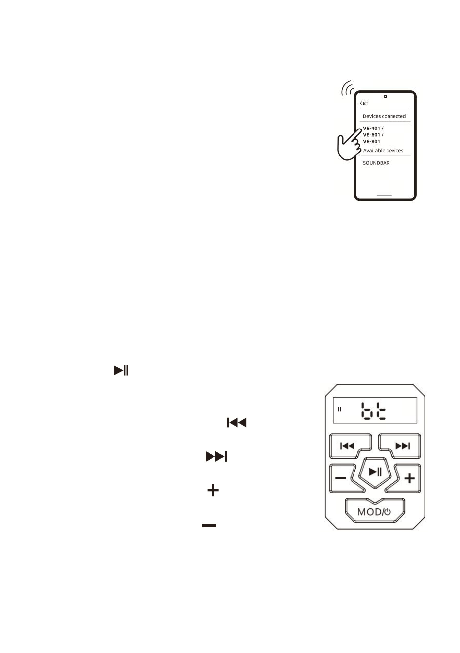
BUTTON OPERATION:
1.Press the key “ ”once to start playing/pause music,
or press the PLAY button from the touch screen of the
device.
2.To select the previous song, click the “ ” button or
use the device control.
3.To select the next song, click the “ ” button or use
the device control.
4.To increase the volume, press the“ ” button or use the
device to control.
5.To reduce the volume, press the“ ” button or use the
device control.
TIPS: For optimal audio performance, Set your mobile device volume to 75% or
higher for optimal audio output.
- 12 -
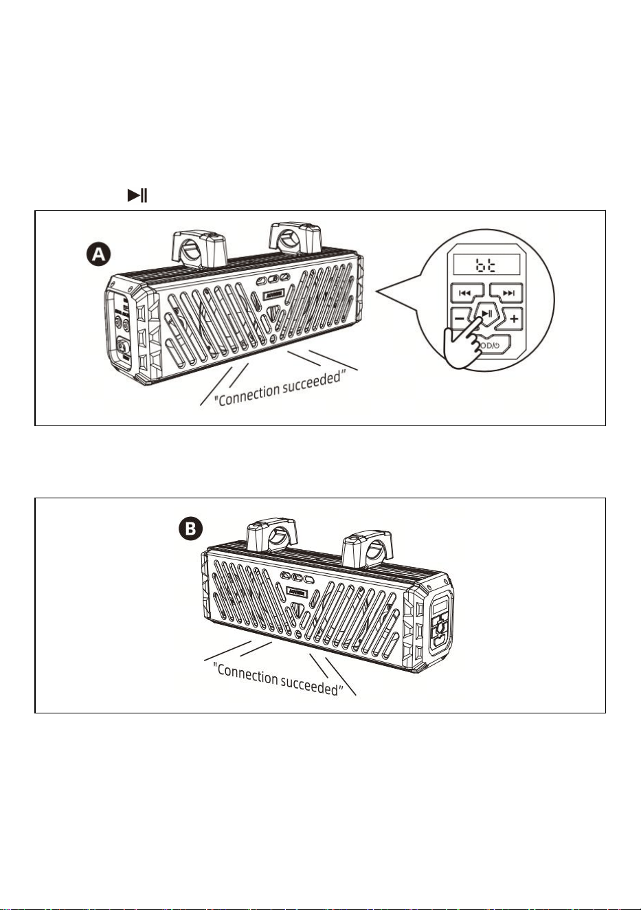
TWS SYNC MODE (TRUE WIRELESS STEREO):
TWS Pairing
1.Prepare two soundbars, power on both units simultaneously, confirm they are in
Bluetooth mode with no active connections, and the "BT" indicator flashing on the
digital display.
a. Pick either unit as the primary master device, then long-press its
Play/Pause" " button to initiate TWS pairing.
b.Once pairing succeeds, both the master and slave units will play a "connection
successful" voice prompt. The "BT" indicator on Unit B (slave) will stay solid on to
confirm the pairing.
c. If TWS pairing keeps failing, move the two units closer together and retry.
2.After successful TWS pairing, the two linked units function as a single system.
They support track switching, play/pause, synchronized volume, audio source
switching, and simultaneous power-off of both units (LED indicators do not sync).
- 13 -
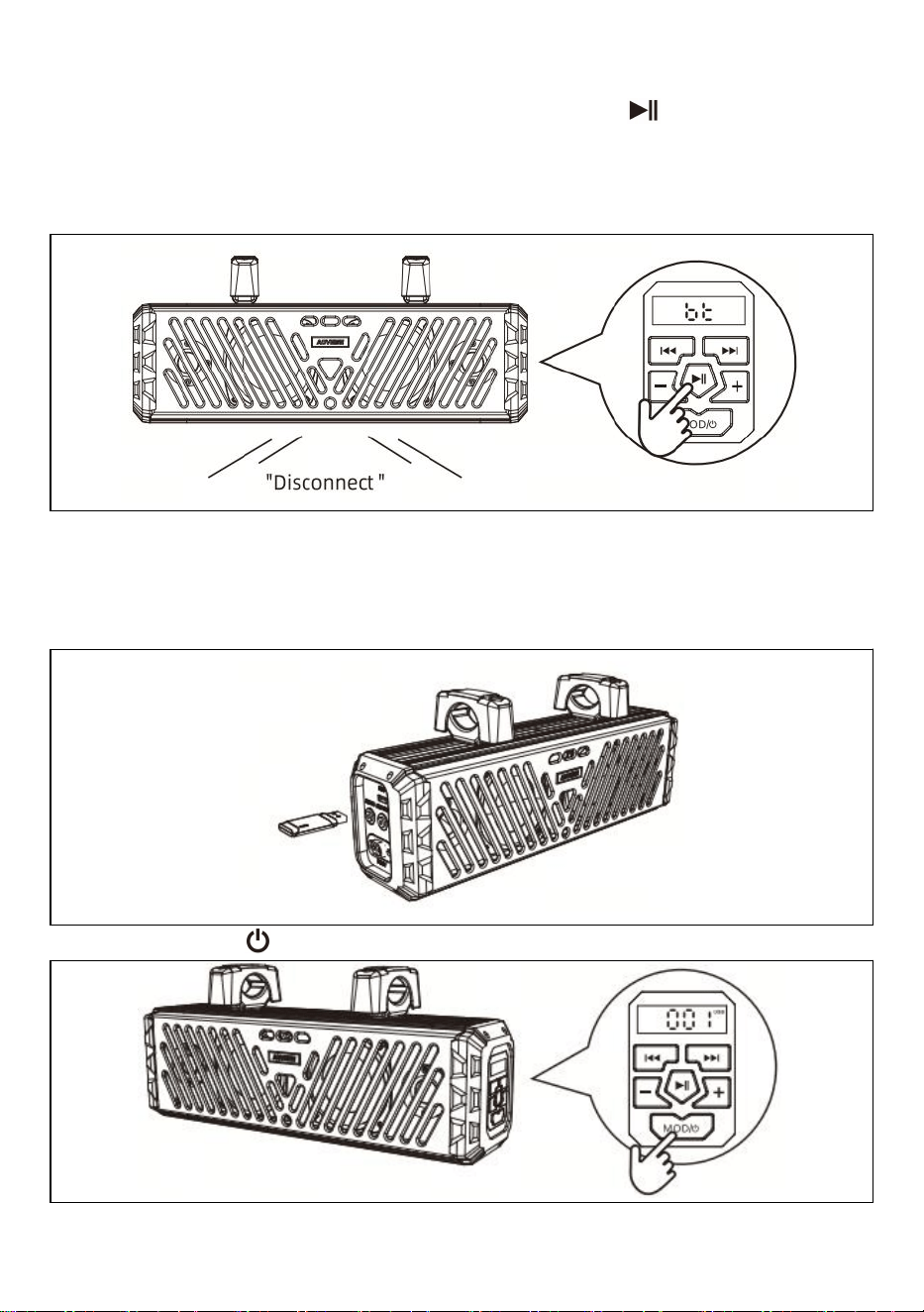
Cancel TWS Pairing
After successful TWS pairing, long-press the Play/Pause " " button for 5
seconds to cancel TWS pairing. The master and slave units will simultaneously
play a "Disconnect" voice prompt to confirm pairing has been cancelled. At this
point, the "BT" indicator on the slave unit will flash.
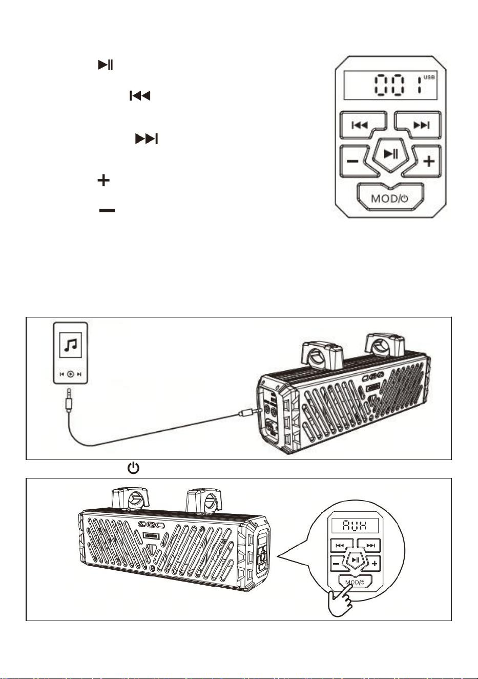
USB INPUT:
USB Input Operation
1.Insert the USB flash drive into the soundbar.
2.Press the "MOD/ " button to switch the soundbar to USB mode.
- 14 -
Button Operation
1.Press the " " button once to play or pause music.
2.Short-press the " " button to switch to the previous
track; long-press the button for fast rewind.
3.Short-press the " " button to switch to the next
track; long-press the button for fast forward.
4.Press the " " button to increase the volume.
5.Press the " " button to decrease the volume.
TIPS: The USB mode supports MP3 and WMA audio formats.
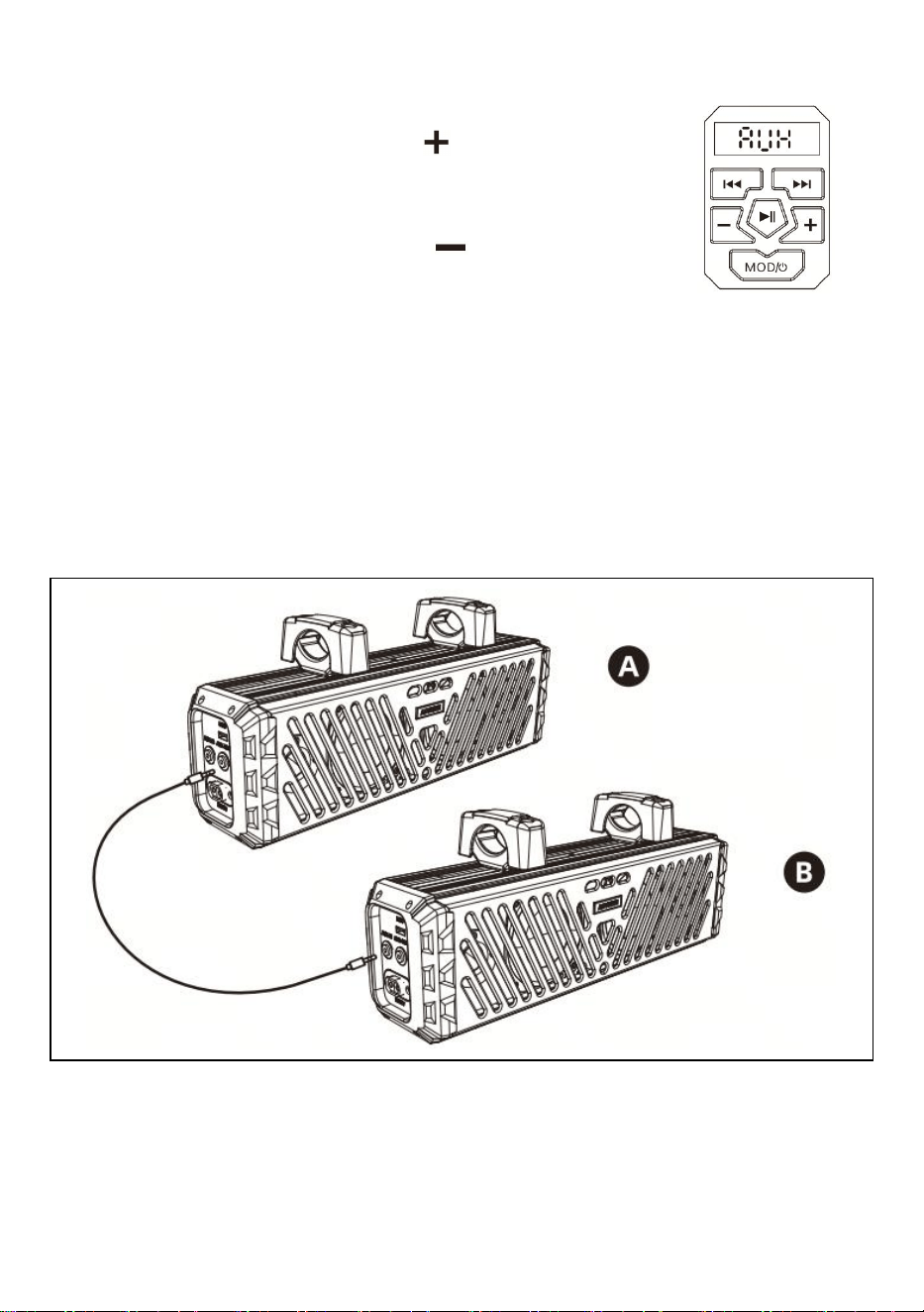
AUX INPUT:
Aux Input Operation
1.Connect a 3.5mm AUX audio cable to the unit’s AUX-IN jack.
2.Press the "MOD/ " button to switch the soundbar to AUX mode.
Audio player with 3.5mm
audio output jack
- 15 -
Button Operation
1.To increase the volume, press the " " button.
2.To decrease the volume, press the " " button.
TIPS: The soundbar can play audio from any device equipped with a 3.5 mm
headphone jack.
AUX OUT:
Aux Out Operation
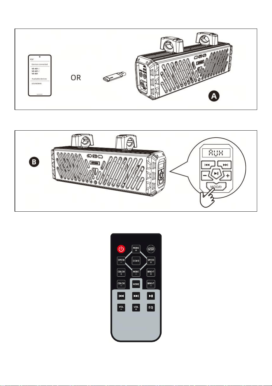
1.To connect two of our soundbars for simultaneous music playback via a 3.5 mm
AUX cable, plug one end into the AUX OUT port of Soundbar A (master unit) and
the other end into the AUX IN port of Soundbar B (slave unit).
- 16 -
2.Soundbar A needs to play music in USB or BT mode.
3.Soundbar B must be set to AUX mode to sync audio playback with Soundbar A.
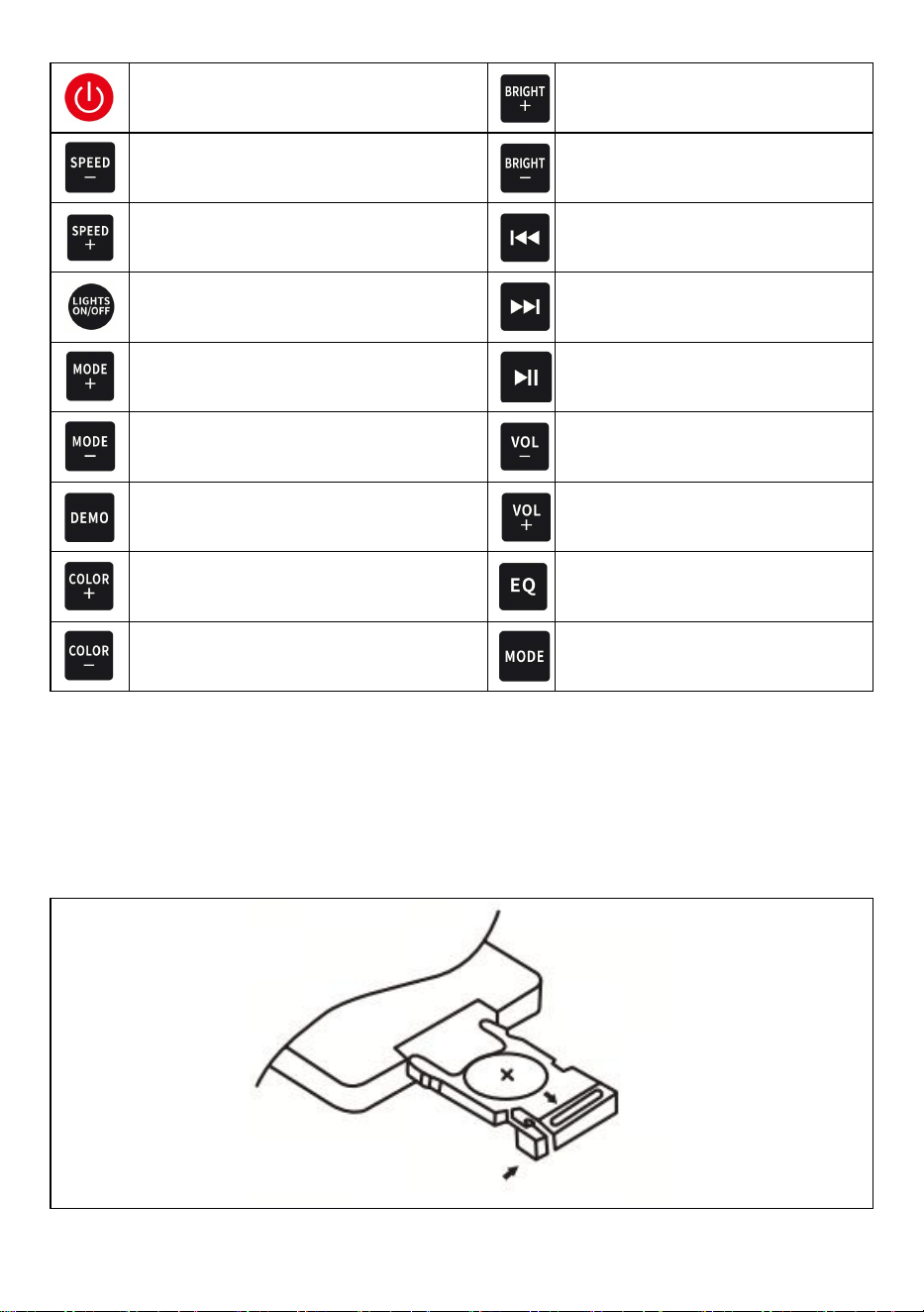
REMOTE CONTROL OPERATION:
- 17 -
On/off key
Light brightness increase key
Light gradient speed decrease key
Light brightness decrease key
Light gradient speed increase key
Up selection key
LIGHTS ON/OFF
Down selection key
Light mode up selection key
Pause/play key
Light mode down selection key
Volume down key
Light default mode restore key
Volume up key
Light color up selection key
Sound effect selection key
Light color down selection key
Mode switching key
CAUTIONS
1.Do not block the remote control with metal objects.
2.Do not store it under direct sunlight.
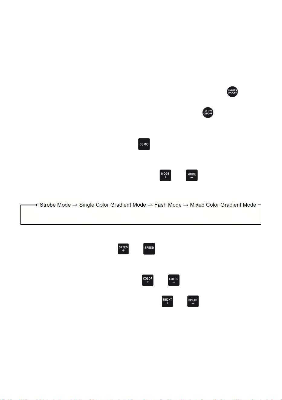
3.No batteries are included with the product. Users shall purchase batteries
of the model and specifications specified for this product separately.
- 18 -
Replacement Battery: CR2032
WARNING:
This remote control contains a coin cell battery. Keep coin batteries away from
children at all times. If swallowed, batteries can cause severe internal burns or
fatal injury within 2 hours. Seek emergency medical assistance immediately.
Function Introduction
1.After powering on, the main unit light bar lights up. Short-press the " " LED
light switch to turn off the main unit light bar. Short-press the " " LED light
switch again to turn the main unit light bar back on.
2.In any working state, Short-press the " " light mode key to restore factory
default; the light bar will switch back to the default strobe mode.
3.In the default lighting mode, Short-press the " " or " " down selection key
to switch lighting modes:
4.When the light mode is set to Single Color Gradient Mode or Mixed Color
Gradient Mode, Short-press the " " or " " gradient speed adjustment key to
speed up or slow down the color transition rate.
5.Under any light mode, Short-press the " " or " " color selection key to
switch light colors. Meanwhile, Short-press the " " or " " brightness
adjustment key in this mode to adjust the light brightness.

- 19 -
FREQUENTLY ASKED QUESTIONS
Q1: Will this soundbar fit my vehicle?
It comes with universal mounting brackets and fits any off-road vehicle equipped
with a 1"–2" roll cage, including UTVs, ATVs, golf carts, marine vessels, boats,
Polaris RZR, Ranger, Can-Am Defender, Maverick, and more.
Q2: Can I turn the LED lights off while playing music?
Yes. The RGB lights can be turned off at any time via the remote control.
Short-press the light button to toggle the lights on and off.
Q3: The soundbar works well when tested with a 12V plug, but fails to power
up when connected to my golf cart battery. Why?
This soundbar runs on 12V DC. The audio system will malfunction if the input
voltage drops below 8V DC or exceeds 18V DC. Many golf cart batteries output
24V, 36V or 48V. Please verify your battery voltage before installation. If the
voltage does not match, a voltage converter is required.
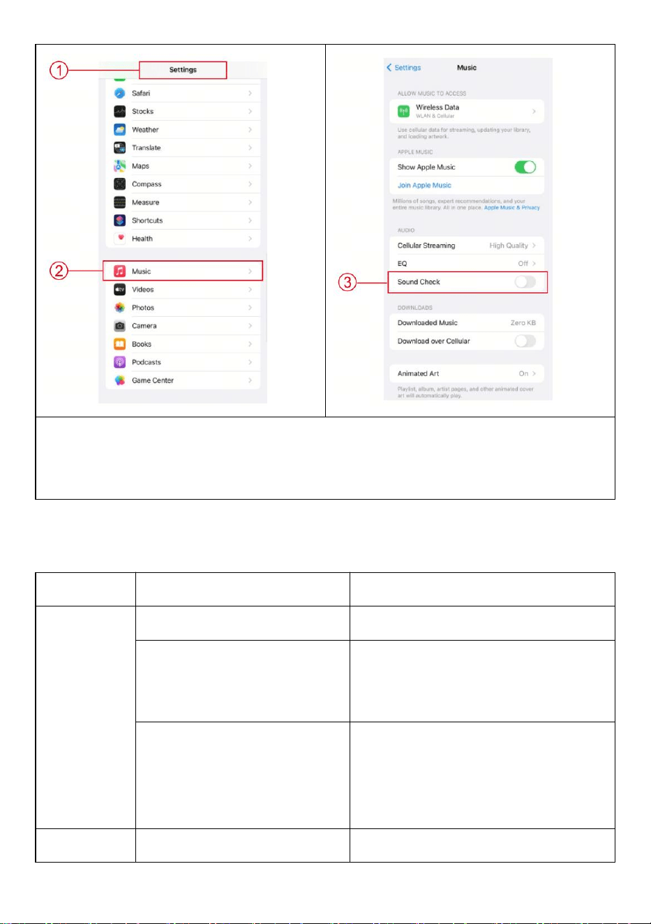
Q4: If the soundbar volume is low when playing music via the default Apple
Music app on your iPhone, follow these steps to boost the volume:
1. Open Settings on your iPhone.
2. Tap Music.
3. Locate Sound Check and toggle it off.
- 20 -
If you are using a third-party music app downloaded from the App Store, please
contact our official customer support team for guidance on adjusting settings to
boost the soundbar volume.
Troubleshooting
TROUBLE
CAUSE
SOLUTION
Device will
not turn on
1. The fuse is blown
1. Check or replace the fuse
2. Vehicle didn’t start / Main
accessory switch not turned
on
2. Start the vehicle / Turn the main
accessory switch to ON position
3. Incorrect operating
voltage
3. This soundbar requires 12V DC
power supply. It will malfunction if
input voltage is lower than 8V DC or
higher than 18V DC.
No sound
1. Soundbar volume is low
1. Turn up the soundbar volume or
- 21 -
output
or muted
cancel mute mode
2. Audio source device
volume is low or muted
2. Increase the volume of your
audio source device
3. Bluetooth, AUX IN or USB
input connection failed
3. Recheck the connection between
the soundbar and audio source
(Bluetooth, AUX IN, USB IN)
Cannot pair
Bluetooth
Bluetooth function of your
audio source device is
disabled
Check your audio source device’s
user instruction manual to turn on its
Bluetooth function
Device not
responding
Power supply fault or signal
interference
Disconnect power for 10 seconds,
then reconnect to reset the device
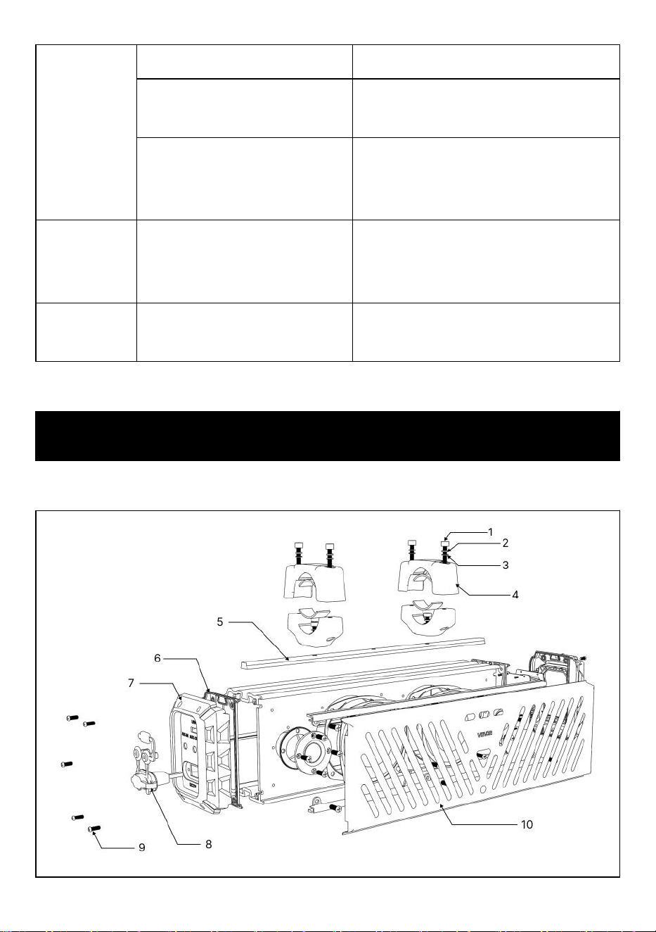
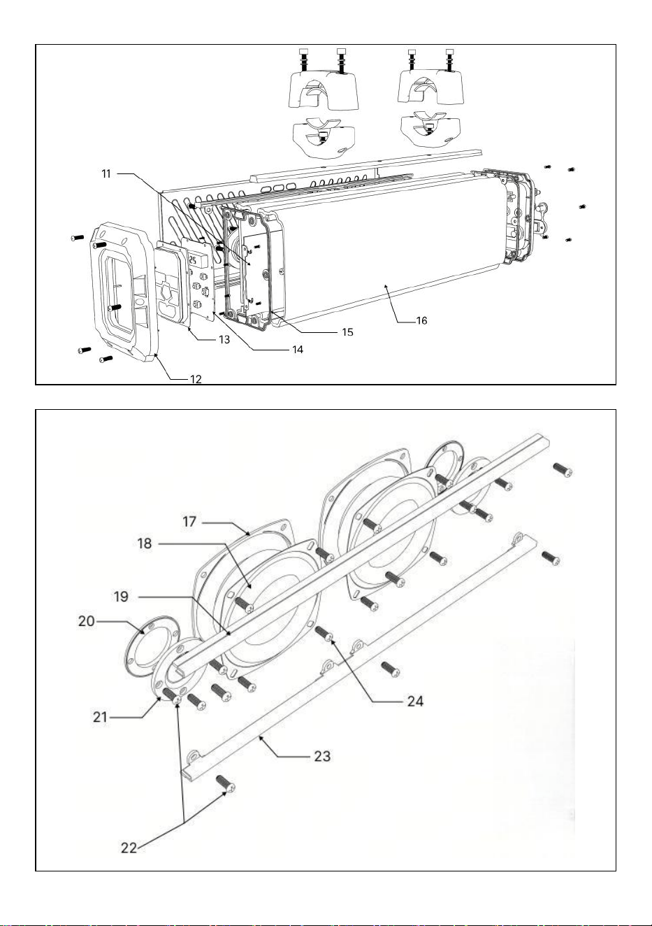
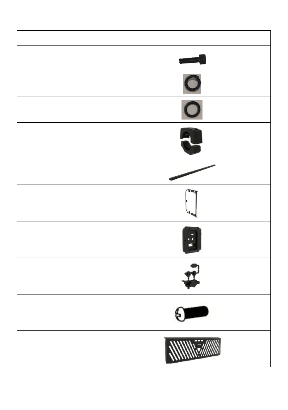
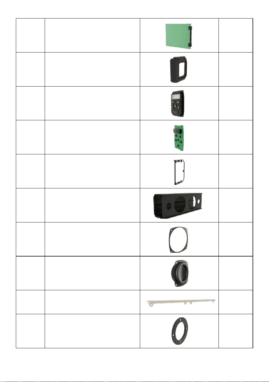
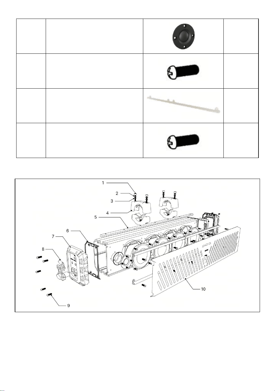
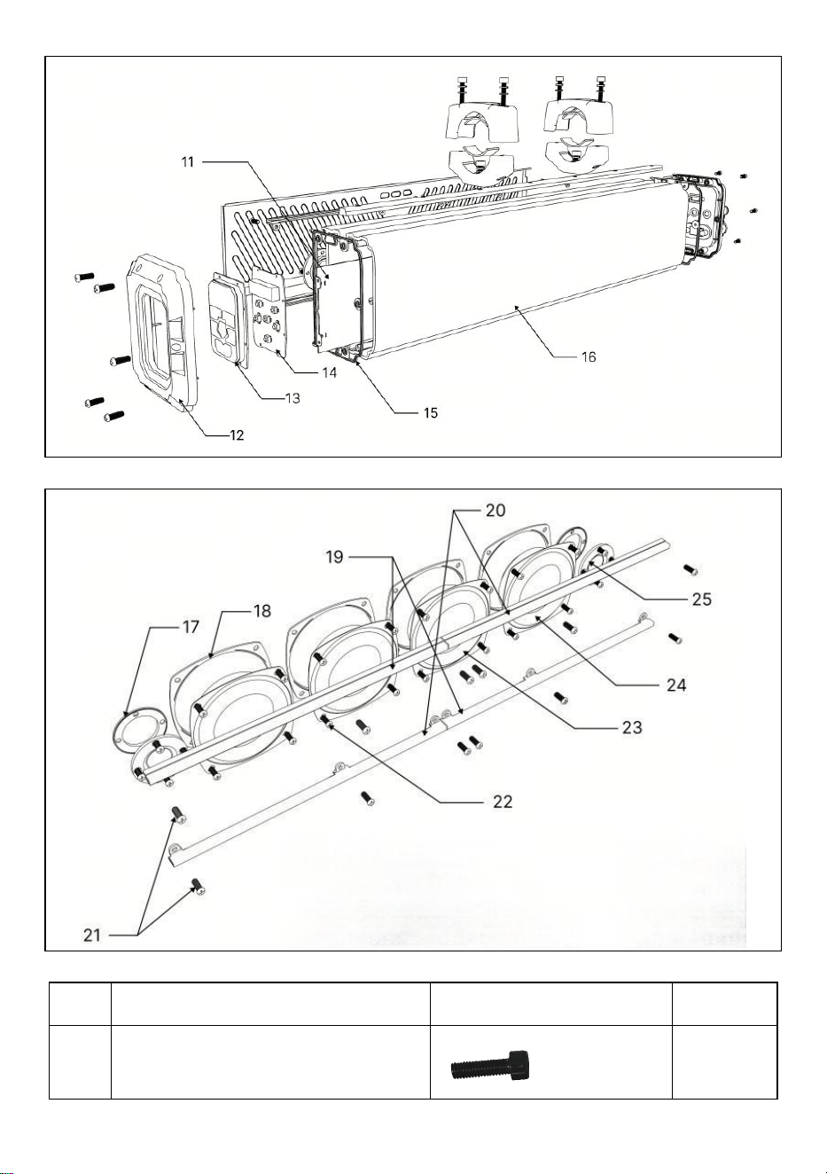
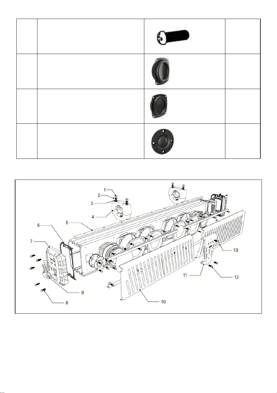
EXPLODED VIEW AND PARTS LIST
Model:VE-401:
- 22 -
- 23 -
No.
Component Name
Component Pictures
QTY
1
M6×40 / M6×60 Hex Bolt
4
2
Spring Washer M6
4
3
Flat Washer M6
4
4
Upper clamp
2
5
Rubber Pad
1
6
Left Side Panel Waterproof
Silicone Pad
1
7
left side panel
1
8
12V Assembly Parts
1
9
Pan Head Self-tapping Screw
BA2.6×14
10
10
Speaker Grille
1
- 24 -
11
12V Main Board Components
1
12
Right Side Panel
1
13
Silicone Button
1
14
12V Button Board Assembly
1
15
Right Side Panel Waterproof
Silicone Pad
1
16
Main Speaker Housing
1
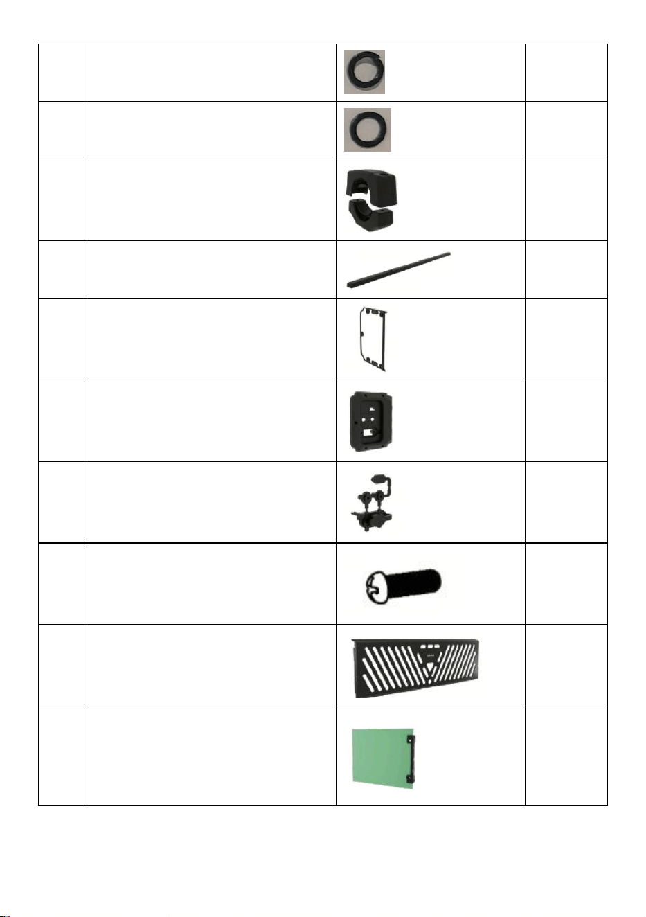
17
4" Speaker Waterproof
Silicone Pad
2
18
4" External Magnet
Mid-Woofer Unit (4 Ω, 20 W)
2
19
Light Transmitting Strip A
1
20
1" Speaker Waterproof
Silicone Pad
2
- 25 -
21
2" Internal Magnet Tweeter
Unit (6 Ω, 15 W)
2
22
Pan Head Self-tapping Screw
PA3.5×10
8
23
Light Transmitting Strip B
1
24
Hex Socket Bolt M4×8
8
Model:VE-601:
- 26 -
No.
Component Name
Component Pictures
QTY
1
M6×40 / M6×60 Hex Bolt
4
- 27 -
2
Spring Washer M6
4
3
Flat Washer M6
4
4
Upper clamp
2
5
Rubber Pad
1
6
Left Side Panel Waterproof
Silicone Pad
1
7
left side panel
1
8
12V Assembly Parts
1
9
Pan Head Self-tapping Screw
BA2.6×14
10
10
Speaker Grille
1
11
12V Main Board Components
1
- 28 -
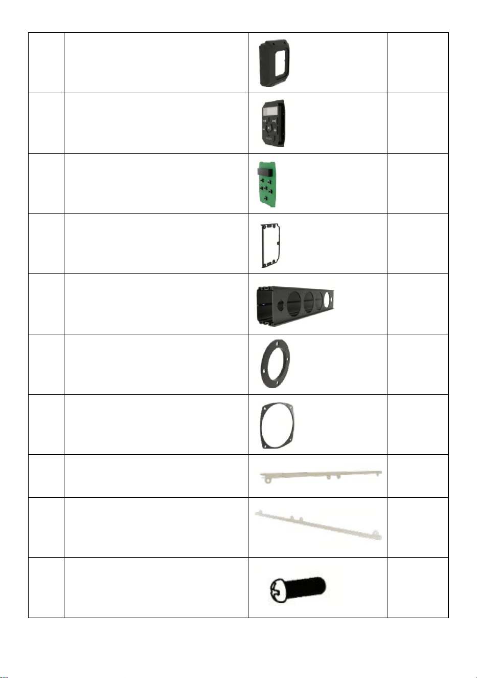
12
Right Side Panel
1
13
Silicone Button
1
14
12V Button Board Assembly
1
15
Right Side Panel Waterproof
Silicone Pad
1
16
Main Speaker Housing
1
17
1" Speaker Waterproof Silicone
Pad
2
18
4" Speaker Waterproof Silicone
Pad
2
19
Light Transmitting Strip A
2
20
Light Transmitting Strip B
2
21
Pan Head Self-tapping Screw
PA3.5×10
8
- 29 -
22
Hex Socket Bolt M4×8
8
23
4" External Magnet Mid-Woofer
Unit (4 Ω, 25 W)
2
24
4" Rubber Speaker Diaphragm
(Without Frame & Light Board)
2
25
2" Internal Magnet Tweeter Unit (6
Ω, 15 W)
2
Model:VE-801:
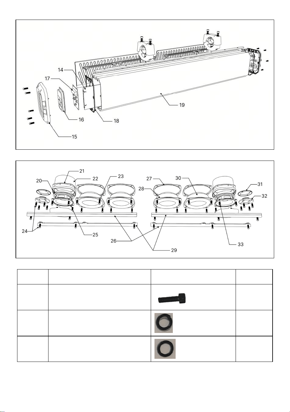
- 30 -
No.
Component Name
Component Pictures
QTY
1
M6×40 / M6×60 Hex Bolt
4
2
Spring Washer M6
4
3
Flat Washer M6
4
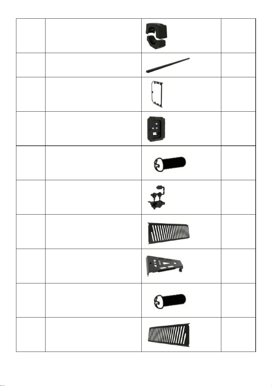
- 31 -
4
Upper clamp
2
5
Rubber Pad
1
6
Left Side Panel Waterproof
Silicone Pad
1
7
left side panel
1
8
Pan Head Self-tapping Screw
BA2.6×14
10
9
12V Assembly Parts
1
10
Left Speaker Grille
1
11
Panel
1
12
Pan Head Self-tapping Screw
BA3.5×12
3
13
Right Speaker Grille
1
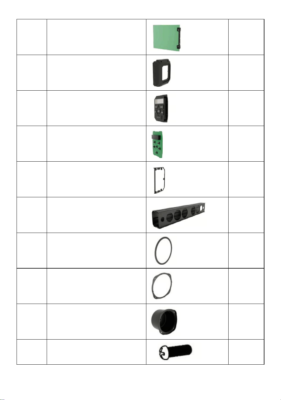
- 32 -
14
12V Main Board Components
1
15
Right Side Panel
1
16
Silicone Button
1
17
12V Button Board Assembly
1
18
Right Side Panel Waterproof
Silicone Pad
1
19
Main Speaker Housing
1
20
3" Speaker Waterproof
Silicone Pad
2
21
Speaker Bottom Housing
Silicone Pad
2
22
Speaker Rear Housing
2
23
Hex Socket Bolt M4×8
24
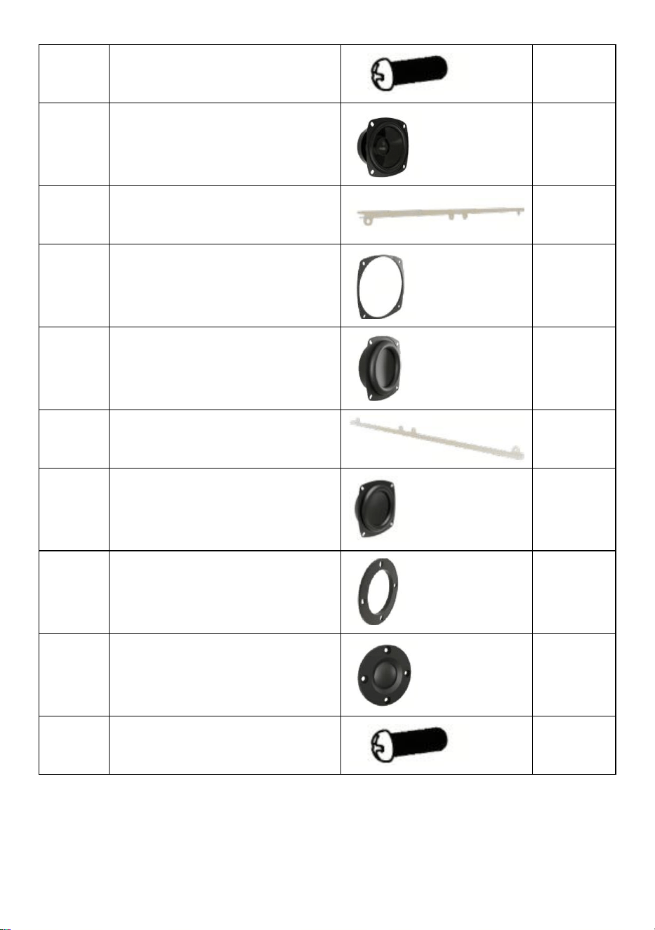
- 33 -
24
Pan Head Self-tapping Screw
PA3.5×10
8
25
Internal Magnet 3" Midrange
Speaker (4 Ω, 15 W)
2
26
Light Transmitting Strip A
2
27
4" Speaker Waterproof
Silicone Pad
2
28
4" External Magnet Woofer
Unit (6 Ω, 30 W)
2
29
Light Transmitting Strip B
2
30
4" Rubber Speaker Diaphragm
(Without Frame & Light Board)
2
31
1" Speaker Waterproof
Silicone Pad
2
32
2" Internal Magnet Tweeter
Unit (6 Ω, 15 W)
2
33
Pan Head Self-tapping Screw
BA3.5×12
8
FCC Caution
Any Changes or modifications not expressly approved by the party responsible for co
mpliance could void the user's authority to operate the equipment.
Note: This equipment has been tested and found to comply with the limits for a Class
B digital device, pursuant to part 15 of the FCC Rules. These limits are designed to pr
ovide reasonable protection against harmful interference in a residential installation. T
his equipment generates uses and can radiate radio frequency energy and, if not instal
led and used in accordance with the instructions, may cause harmful interference to ra
dio communications. However, there is no guarantee that interference will not occur in
a particular installation. If this equipment does cause harmful interference to radio or te
levision reception, which can be determined by turning the equipment off and on, the u
ser is encouraged to try to correct the interference by one or more of the following mea
sures:
-Reorient or relocate the receiving antenna.
-Increase the separation between the equipment and receiver.
-Connect the equipment into an outlet on a circuit different from that to which the recei
ver is connected.-Consult the dealer or an experienced radio/TV technician for help.
*RF warning for Mobile device:
This equipment complies with FCC radiation exposure limits set forth for an uncontroll
ed environment. This equipment should be installed and operated with minimum dista
nce 20cm between the radiator & your body.
- 34 -