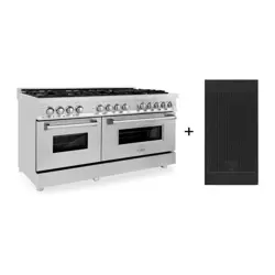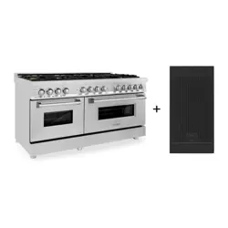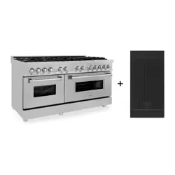

DUAL FUEL RANGES
RA MODELS
zlinekitchen.com
Installation Manual

ZLINE Kitchen and Bath provides Attainable Luxury, where the kitchen and bath of your dreams
is never out of reach. Through our unique designs and unparalleled quality, we’re dedicated to
providing you an elevated experience in the heart of your home. With an endless selection of
features and finishes, our inspiration is your reality.

ZLINE is fueled by a passion for innovation; A relentless pursuit of bringing the
highest end luxury designs and professional features into everyone’s homes.
Because we continually strive to improve our products, we may change
specifications and designs without prior notice.
Scan the QR code to view the most up-to-date version of the Installation
Manual and User Manual.
WARNING: This product can expose you to chemicals including nickel, which is known to the
State of California to cause cancer. For more information, go to www.P65Warnings.ca.gov.

IMPORTANT SAFETY INSTRUCTIONS . . . . . . . . . . . . . . . . . . . 1
BEFORE INSTALLATION . . . . . . . . . . . . . . . . . . . . . . . . . . . . . . . 9
Product Dimensions . . . . . . . . . . . . . . . . . . . . . . . . . . . . . . . . 9
Type of Gas . . . . . . . . . . . . . . . . . . . . . . . . . . . . . . . . . . . 12
Gas Pressure . . . . . . . . . . . . . . . . . . . . . . . . . . . . . . . . . . . 12
INSTALLATION . . . . . . . . . . . . . . . . . . . . . . . . . . . . . . . . . . . . . 13
Installing the Legs . . . . . . . . . . . . . . . . . . . . . . . . . . . . . . . . 13
Installing the Anti-Tip System . . . . . . . . . . . . . . . . . . . . . . . . . . 14
Installation Requirements And Cutouts . . . . . . . . . . . . . . . . . . . . . 15
Installation Adjacent to Kitchen Cabinets . . . . . . . . . . . . . . . . . . . 15
Electric Power Rating . . . . . . . . . . . . . . . . . . . . . . . . . . . . . . 17
Gas Connection . . . . . . . . . . . . . . . . . . . . . . . . . . . . . . . . . 18
Liquid Propane Conversion Procedure . . . . . . . . . . . . . . . . . . . . . 21
Installation Checklist . . . . . . . . . . . . . . . . . . . . . . . . . . . . . . . 28
Final Preparation . . . . . . . . . . . . . . . . . . . . . . . . . . . . . . . . 28
WARRANTY . . . . . . . . . . . . . . . . . . . . . . . . . . . . . . . . . . . . . . . . 29
TABLE OF CONTENTS
1
Gas Safety
IMPORTANT SAFETY INSTRUCTIONS
GAS SAFETY
WARNING
WARNING: If the information in these
instructions is not followed exactly, a fire
or explosion may result causing property
damage, personal injury or death.
• Do not store or use gasoline or other flammable vapors and liquids in the vicinity
of this or any other appliance.
• WHAT TO DO IF YOU SMELL GAS
• Do not try to light any appliance.
• Do not touch any electrical switch.
• Do not use any phone in your building.
• Immediately call your gas supplier from a neighbor’s phone. Follow the gas
supplier’s instructions.
• If you cannot reach your gas supplier, call the fire department.
• Installation and service must be performed by a qualified installer, service agency
or the gas supplier.
2
Gas Safety
IMPORTANT SAFETY INSTRUCTIONS
AVERTISSEMENT
AVERTISSEMENT : Le non-respect à
la lettre de ces instructions peut causer
un incendie ou une explosion, qui
pourrait entraîner des dommages
matériels, desblessures ou la mort
• Ne pas entreposer ou utiliser d’essence ou tout autre liquide ou gaz
inflammable à proximité de cet appareil ou de tout autre appareil.
• EN PRÉSENCE D’UNE ODEUR DE GAZ :
• Ne tenter d’allumer aucun appareil ;
• Ne toucher à aucun commutateur électrique ;
• N’utiliser aucun téléphone dans l’immeuble ;
• Appeler immédiatement le fournisseur de gaz à partir d’un téléphone situé
à l’extérieur de l’immeuble ; Suivre les instructions du fournisseur de gaz ;
• S’il est impossible de joindre le fournisseur de gaz, appeler le service
des incendies.
• L’installation et la réparation doivent être effectuées par un installateur
ou une agence de réparation ayant les qualifications requises ou par le
fournisseur de gaz.

3
Gas Safety
IMPORTANT SAFETY INSTRUCTIONS
WARNING
WARNING:
Never Operate the Top Surface Cooking Section of this Appliance Unattended.
• Failure to follow this warning statement could result in fire, explosion, or burn
hazard that could cause property damage, personal injury, or death.
• If a fire should occur, keep away from the appliance and immediately call
your fire department. DO NOT ATTEMPT TO EXTINGUISH AN OIL/GREASE
FIRE WITH WATER.
ATTENTION
ATTENTION :
Ne faites jamais fonctionner la surface de cuisson, sur le dessus de cet appareil, sans
surveillance.
• Le non-respect de cette mise en garde pourrait entraîner un incendie, une
explosion ou un risque de brûlure et ainsi causer des dommages matériels, des
blessures ou la mort.
• Si l’appareil prend feu, tenez-vous à l’écart et appelez immédiatement votre
service des incendies. NE TENTEZ JAMAIS D’ÉTEINDRE UN FEU DE GRAISSE
OU D’HUILE EN L’ASPERGEANT D’EAU.
4
Gas Safety
IMPORTANT SAFETY INSTRUCTIONS
WARNING
WARNING: Never use this appliance as a space heater to heat or
warm the room. Doing so may result in carbon monoxide poisoning
and overheating. Never use the top of the range or the interior of the
oven as a storage areas, as items could melt or ignite, increasing the
risk of fire, damage, and/or serious injury.
AVERTISSEMENT
AVERTISSEMENT: Ne JAMAIS utiliser cet appareil électroménager en
guise de chaufferette. Le fait de chauffer une pièce ainsi peut entraîner un
empoisonnement au monoxyde de carbone ou une surchauffe du four.
WARNING
WARNING: NEVER cover any slots, holes or passages in the oven
bottom or cover an entire rack with materials such as aluminum foil.
Doing so blocks airflow through the oven and may cause carbon
monoxide poisoning. Aluminum foil linings may also trap heat, causing
a fire hazard.
AVERTISSEMENT
AVERTISSEMENT:Ne JAMAIS recouvrir une fente, un trou ou une
conduite dans le fond du four ni recouvrir entièrement une grille d’un
matériau comme du papier d’aluminium. Un tel revêtement bloque la
circulation d’air dans le four, ce qui peut entraîner un empoisonnement
au monoxyde de carbone. De plus, le papier d’aluminium peut
emprisonner la chaleur, ce qui risque de provoquer un incendie.

5
IMPORTANT SAFETY INSTRUCTIONS
Installation Safety
WARNING
If the information in this manual is not followed exactly, a fire or explosion
may result causing property damage, personal injury, or death.
• Before beginning installation, please read and follow these important instructions for the
safety of your home and the people living in it.
• The manufacturer will not be responsible for any damage to property or to persons
caused by incorrect installation, improper use of the appliance, or failure to heed the
warnings listed.
• The manufacturer reserves the right to make changes to its products when considered
necessary and useful, without affecting the essential safety and operating characteristics.
• This appliance has been designed for non-commercial, domestic use only.
• Please observe all local, state, and national codes and ordinances. Please ensure the
range is properly grounded. The plug should always be accessible. Installation must
conform with local codes, or in the absence of codes, the National Fuel Gas Code ANSI
Z223.1/NFPA 54.
• The installer should leave these instructions with the consumer who should retain for local
inspectors’ use and for future reference. Electrical installation must be in accordance with
the National Electrical Code ANSI/NPA70-latest edition and/or local codes.
• In Massachusetts: Installation must be performed by a “Massachusetts” licensed plumber
or gasfitter. A T-handle type manual gas valve must be installed in the gas line connected
to this appliance.
• In Canada: Installation must be in accordance with the current CAN/CGA-fe 149.1
natural gas installation code or CAN/CGA-B 149.2 propane installation code and/
or local codes. Electrical installation must be in accordance with the current CSA C22.1
Canadian electrical codes Part 1 and/or local codes.
• The installation of appliance designed for manufactured (mobile) home installation must
conform with the Manufactured Home Construction and Safety Standard, Title 24CFR,
Part 3280 [formerly the Federal Standard for Mobile Home Construction and Safety,
Title 24, HUD (Part280)] or with local codes where applicable.
• Installation of any gas-fired equipment should be made by a licensed plumber. A manual
gas shut-off valve must be installed in the gas supply line for safety and ease of service.

6
IMPORTANT SAFETY INSTRUCTIONS
WARNING
An air curtain or other overhead range/range top hood, which operates
by blowing downward airflow onto the range, shall not be used/installed
in conjunction with this gas range top.
• Please ensure that the altitude of your home is conducive for the use of gas cooking
products. If the product is installed at higher altitudes above sea level, you may experience
issues with gas pressure that will affect product performance. Please consult your local
gas company for recommendations before purchasing or installing.
• Do not store or use gasoline or any other flammable substances in the vicinity of this or
any other appliance.
• NEVER use this appliance as a space heater to heat or warm the room. Doing so may
result in carbon monoxide poisoning.
• NEVER cover any slots, holes, or passages. Doing so blocks air flow and may cause
carbon monoxide poisoning. Aluminum foil linings may also trap heat, causing a
fire hazard.
• If a gas leak is detected, refer to the “WHAT TO DO IF YOU SMELL GAS”
alert on page 1.
• Installation and service on this product must be performed by a qualified installer,
servicer, or gas supplier.
• Know how to shut off gas supply at the meter and disconnect the electrical power to the
appliance at the circuit breaker or fuse box in case of an emergency. Installers should
also show appliance owners the location of the appliance gas shut-off valve and how
to shut it off if necessary.
• If the appliance is located near a window, NEVER hang long curtains or paper blinds
on that window. They could blow over the surface burners and ignite, potentially causing
a fire hazard.
• Keep the appliance area clear and free from combustible materials, gasoline, and other
flammable vapors and liquids.
Gas Safety

7
Ventilation Safety
IMPORTANT SAFETY INSTRUCTIONS
VENTILATION SAFETY
• The use of a gas cooking appliance generates heat and humidity in the kitchen or room
where it is installed. An range hood may be used with the appliance; in each case it shall
be installed in conformity with the appropriate national and local standards.
• If a range hood is installed with appropriate ducting, maintain a 30" (762 mm) minimum
clearance between the cooking surface and bottom of the hood.
• Exhaust hood operation may affect other vented appliances; in each case it shall be
installed in conformity with the appropriate national and local standards.
• Intensive and continuous use of the appliance may require additional ventilation, for
example, by opening a window.
OVEN SAFETY
• Never pour cold water onto hot surfaces in a hot oven. The steam created could cause
serious burns or scalding and the sudden change in temperature can damage the enamel
in the oven.
• We recommend that before you cook in your new range, you heat the oven to roughly
400 °F (204 °C) for 2 hours. After the oven cools, wipe it out with hot water and a
kitchen-safe cleaner. We also recommend cleaning the racks and shelves before use.
• When using the oven for the first time you may notice the following:
• There may be a smell. This is quite normal when the appliance is first heated, as
residual oil from production of parts will be burnt off quickly.
• There may be noises. This is also quite normal as new parts move and settle into
place during the initial heating process.
COOKING AND RANGE TOP SAFETY
• This product is intended for the cooking of food and must not be used for other purposes.
• Unstable or deformed pans should not be placed on the burners in order to avoid
accidents caused by spillover.
• Particular care should be taken when cooking with oil or fat.
• Always ensure that the knobs are in the OFF position when the appliance is not in use.
• Before maintenance and cleaning, disconnect the appliance and allow cooling down.
For reasons of hygiene and safety this appliance must always be kept clean.
• Take care when using cleaning products in spray form: never direct the spray onto the
electrical wiring, thermostat, and bulb.

8
Cooking Safety
IMPORTANT SAFETY INSTRUCTIONS
• Any food or liquid spills in the bottom of the oven must be cleaned up before cooking in
order to avoid unpleasant smoke and/or the possibility of fire.
• Ensure air can circulate around the gas appliance. Poor ventilation can result in lack of
oxygen and extinguish the flame.
• Supply the appliance with the type of gas stamped on the relevant label situated in the
immediate vicinity of the gas connection tube.
• The appliance is heavy (roughly 250 lb/113 kg) — move it carefully.
• To facilitate ignition, light burners before placing pans. Check that flames are regular.
• Always lower the flame or turn it off before removing the pan.
• Do NOT store items of interest to children in the cabinets above the appliance or on the
back splash of appliance.
• DO NOT use decorative surface burner covers. If a burner is accidentally turned on, the
decorative cover will become hot and possibly melt. You may not be able to see that the
burner is on, and burns may occur if the hot covers are touched.
• DO NOT use stove top grills on your gas appliance. If you use a stove top grill on a
sealed gas burner, it may cause incomplete combustion and can result in exposure to
carbon monoxide levels above allowable current standards.
• DO NOT leave children alone or unattended when the appliance is hot or in operation,
even if burners have been off for several minutes. The unit’s knobs and cooktop may still
have residual heat, and children could be seriously burned.
• DO NOT let anyone climb, stand, or hang on the unit. They could damage the range or
cause it to tip over which could result in severe personal injury.
• Never modify or alter the construction of the appliance by removing panels, wire covers,
or any other part of the product.
• DO NOT wear loose-fitting or hanging garments while using the appliance. DO NOT
let clothing or other flammable materials contact hot surfaces.
• Only certain types of glass, glass/ceramic, ceramic, earthenware, or other glazed
cookware are suitable for use without breaking due to sudden changes in temperature.
Check the manufacturer’s recommendations for appliance use.
• DO NOT install the unit without securing it to the cabinetry or wall with the anti-tip chains.
9
BEFORE INSTALLATION
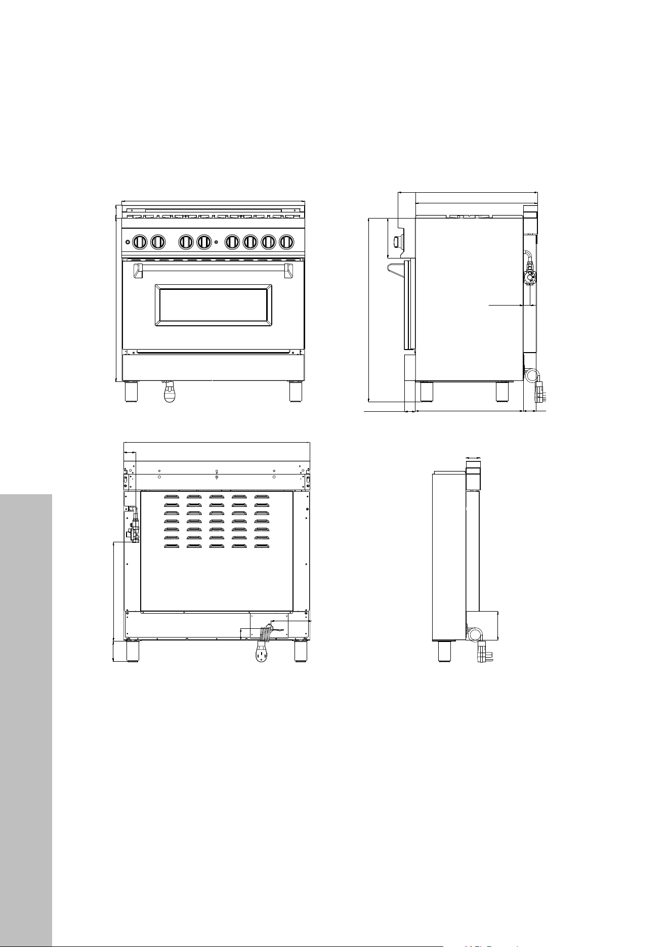
PRODUCT DIMENSIONS
36 1/8" (816 mm)
1 1/4" (32 mm)
27 1/2" (699 mm)
24" (610 mm)
A
7 7/8"
(200 mm)
2 1/2"
(64 mm)
32 1/8" (816 mm)
21 1/4" (540 mm)2 1/8" (54 mm) 2 1/2" (64 mm)
4"
(102 mm)
2 3/4"
(70 mm)
D
B
A
C
E
F
NOTE: The above diagram is of the RA36 model; the measurements listed without a letter
are universal across all RA models. See the next page for dimensions by model, and for in-
depth product and cutout dimensions, see pages 15–16.
Product Dimensions
10
BEFORE INSTALLATION
PRODUCT DIMENSIONS (CONTINUED)
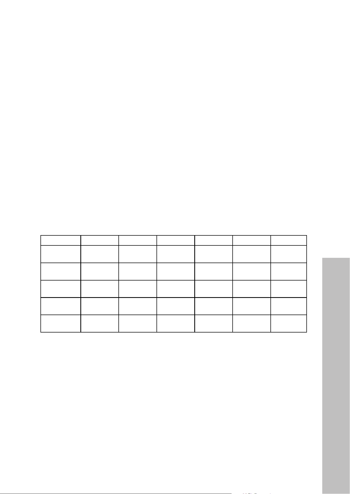
NOTE: Product width (“A”) changes depending on size of range:
• RA24 series ranges: Actual product width is 23 7/8" (606 mm)
• RA30 series ranges: Actual product width is 29 3/4" (756 mm)
• RA36 series ranges: Actual product width is 35 3/4" (908 mm)
• RA48 series ranges: Actual product width is 47 3/4" (1213 mm)
• RA60 series ranges: Actual product width is 59 7/8" (1521 mm)
NOTE TO INSTALLERS: Additional dimensions by letter from the previous page are outlined
below. While these dimensions are similar across all models, they do vary slightly depending
on the size of the range, so be sure to take these into account when hooking the unit up to
its electrical and gas supplies.
RANGE SIZE A B C D E F
RA24
series ranges
23 7/8"
(606 mm)
1 7/8"
(48 mm)
18 1/4"
(464 mm)
7 1/2"
(191 mm)
2 1/2"
(64 mm)
6"
(152 mm)
RA30
series ranges
29 3/4"
(756 mm)
2"
(51 mm)
19"
(483 mm)
7"
(178 mm)
2 1/2"
(64 mm)
5 7/8"
(149 mm)
RA36
series ranges
35 3/4"
(908 mm)
2 1/4"
(57 mm)
18 3/4"
(476 mm)
8"
(203 mm)
2 1/2"
(64 mm)
5 7/8"
(149 mm)
RA48
series ranges
47 3/4"
(1213 mm)
2"
(51 mm)
19"
(483 mm)
5"
(127 mm)
2"
(51 mm)
5 1/2"
(140 mm)
RA60
series ranges
59 7/8"
(1521 mm)
2"
(51 mm)
19"
(483 mm)
5 3/4"
(146 mm)
2"
(51 mm)
5"
(127 mm)
Product Dimensions
11
BEFORE INSTALLATION
GAS SUPPLY
• This appliance shall only be installed by an authorized professional.
• If local codes permit, a flexible metal appliance connection with the new AGA or
CGA certified design, 3/4" (19 mm), is recommended for connecting this appliance
to the gas supply line. DO NOT bend or damage the flexible connector when moving
the appliance.
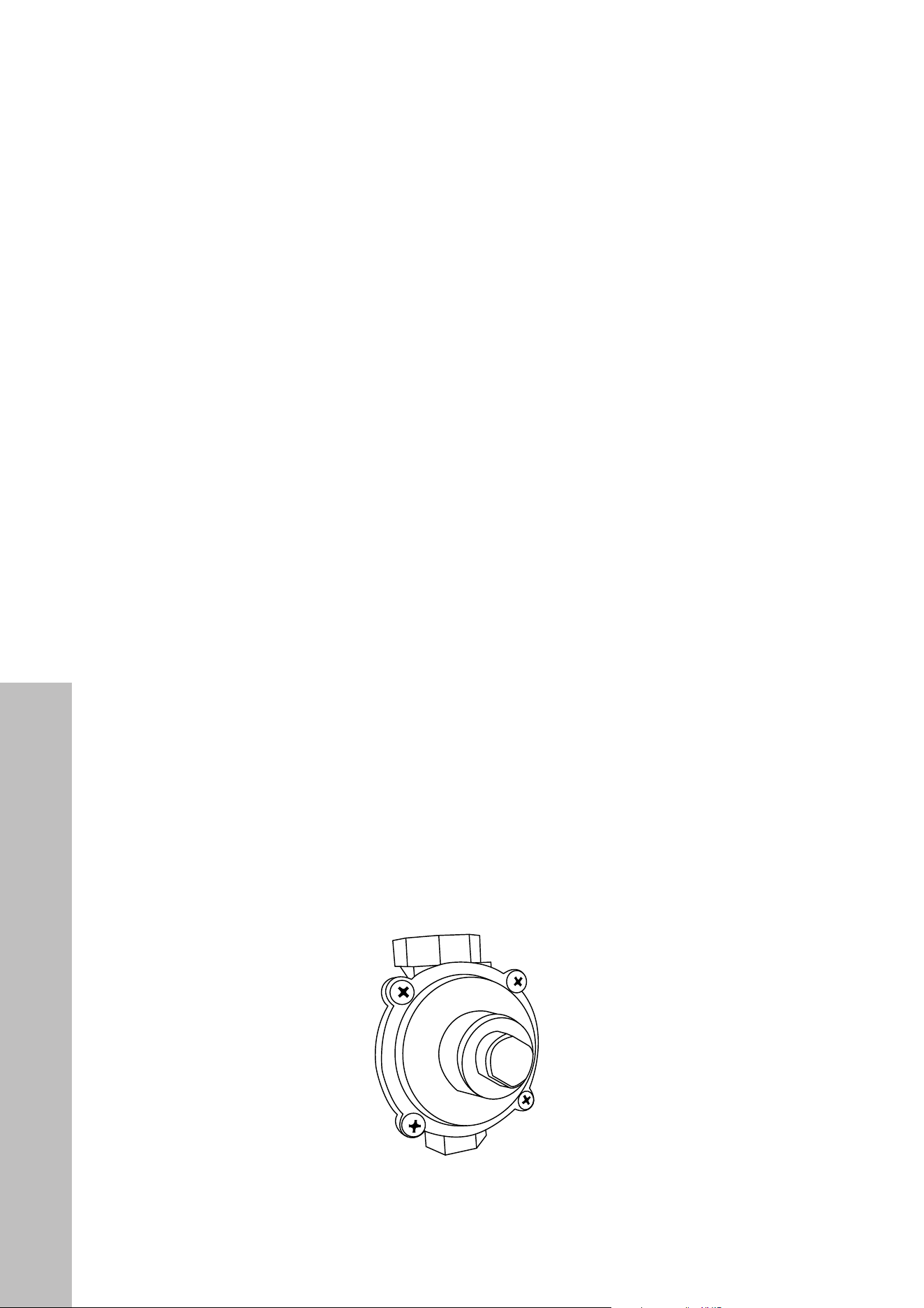
• This appliance must be used with the pressure regulator provided (see below). The
regulator must be properly installed in order to be accessible when the appliance is
installed in its final location. The pressure regulator must be set for the type of gas to
be used. The pressure regulator has 1/2" (13 mm) connection female pipe thread. The
appropriate fitting must be determined based on the size of your gas supply line, the
flexible metal connector, and the shut-off valve.
• The appliance must be isolated from the gas supply piping system by closing its individual
manual shut-off valve during any pressure testing of the gas supply piping system at test
pressures equal to or less than 1/2 psi (3.4 kPa).
• All opening holes in the wall and floor, back and under the appliance shall be sealed
before installation of the appliance.
• A manual valve shall be installed in an accessible location in the gas line external to the
appliance for the purpose of turning on and shutting off the gas to the appliance.
Do not use aerosol sprays in the vicinity of this appliance
while it is hot.
WARNING
Pressure Regulator
Gas Supply

12
BEFORE INSTALLATION
ROOM VENTILATION
An exhaust fan may be used with the appliance; in each case it shall be installed in conformity
with the appropriate national and local standards. Exhaust hood operation may affect other
vented appliances; in each case it shall be installed in conformity with the appropriate
national and local standards.
TYPE OF GAS
This appliance is shipped from the factory for use with natural gas. For use with liquid
propane gas, please follow the conversion procedure described on page 21. A step by
step conversion procedure is also included with each set of liquid propane gas orifices.
GAS PRESSURE
• The maximum inlet gas supply pressure incoming to the gas appliance pressure regulator
is 1/2 psi (3.4 kPa).
• The minimum gas supply pressure for checking the regulator setting shall be at least
1" W.C.P. (0.25 kPa) above the inlet specified manifold pressure to the appliance. This
operating pressure is 4" W.C.P. (1 kPa) for natural gas and 10" W.C.P. (2.75 kPa) for
liquid propane gas.
• Range top requires 6" (152 mm) minimum side wall spacing above the counter height
for proper combustion. Please review specific model installation instructions for required
dimensions; 30"–36" (762 mm–914 mm) between the range top and bottom of the
range hood above, 1/4" (6 mm) for sides below countertop height.
NOTE: Please consult your local building codes for variations with installation.
Room Ventilation
13
INSTALLATION
INSTALLING THE LEGS
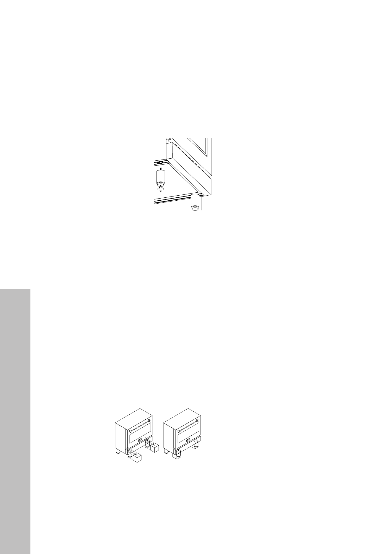
The ranges must be used with the legs properly installed. Height-adjustable legs are shipped
with the range in a foam container above the range. Legs are 4" (102 mm) tall and can be
adjusted up to 2 1/2" (64 mm) for a maximum height of 6 1/2" (165 mm).
Installing the Legs
4" (102 mm)
Before installing the legs, position the appliance near its final location, as the legs are not
suitable for moving the appliance over long distances.
1. After unpacking the range, raise it enough to insert the legs in the appropriate receptacles
situated on the lower part of the appliance. Lower the range gently to keep any undue
strain from legs and mounting hardware.
2. Adjust leg height to the desired level by twisting the inside portion of the leg assembly
until the proper height is reached. Check with a level that the range is perfectly level.
INSTALLING THE SQUARE COVERS
Some ranges come with attachable square leg covers. To install, loosen the round leg from
the range to accommodate for the square leg. Align the top of the square leg (with the slit)
to the top of the round legs and slide in. Adjust the square leg and the round leg until they
are flush with the ground.
NOTE: If the range is not level, the cooking will be uneven. When adjusting the legs, ensure
they are the same height.
Installing the Legs
14
INSTALLATION
INSTALLING THE ANTI-TIP SYSTEM
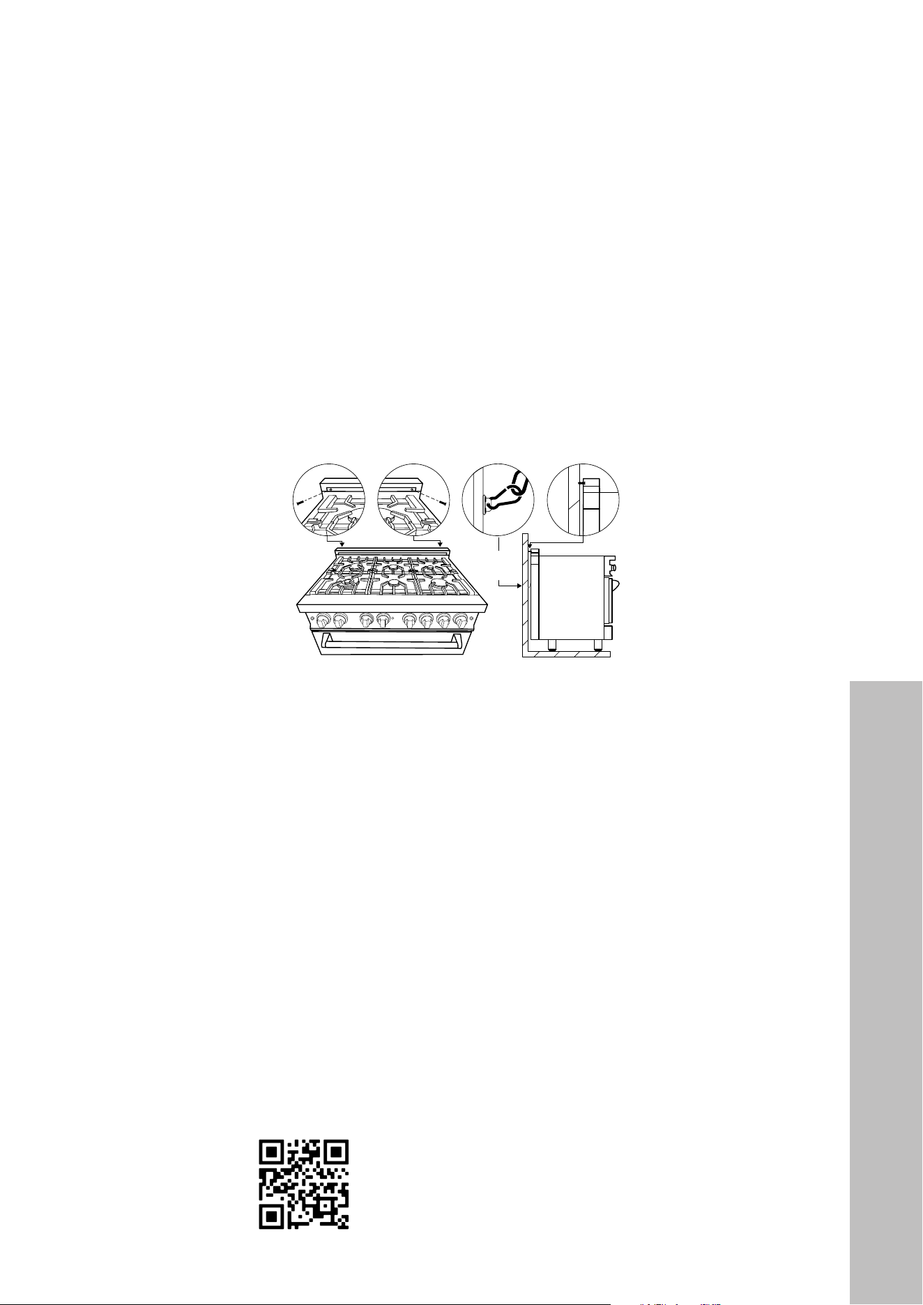
The chains shipped with the range must be properly secured to studs on the rear wall. The
height of the chain from the floor must be determined after the range legs have been adjusted
to the desired height and after the range has been leveled.
A child or adult can tip the range and be fatally injured; take care to adjust the
chains if the range is moved. Failure to do so can result in death or serious injury.
WARNING
Figure 1 Figure 2 Figure 3
Gap distance:
2 1/4" (57 mm)
1. Measure the distance from the floor to where the chains connect on the back of the appliance.
2. Position the ends of the chains on the wall at the desired height and add an extra 1/8"
(3 mm) to ensure stability. Mark each location with a pencil. The chains must be placed at
2 1/4" (57 mm) from the back of the range (see Figure 2 above).
3. Pre-drill holes at the marked locations on the wall.
4. Slide the range against the wall, feed Phillips head screws through each chain, and tighten
using a stub screwdriver or drill with a 90° adapter. Refer to Figure 2 above.
5. Check to see that the chains are connected properly. Then grasp the top rear edge of the
range and carefully attempt to tilt it forward. Verify that the chains are engaged.
6. You may also secure the range with fixed screws on the wall by drilling screws through the
holes in the false exhaust plate at the top rear edge of the range (see Figures 1 and 3).
NOTE: If your wall is not suitable for installation, chains and/or screws should be fixed to an
appropriate cabinet structure.
Scan to follow along with a video.
Installing the Anti-Tip System

15
Installation Requirements
INSTALLATION REQUIREMENTS AND CUTOUTS
GAS VALVE LOCATION
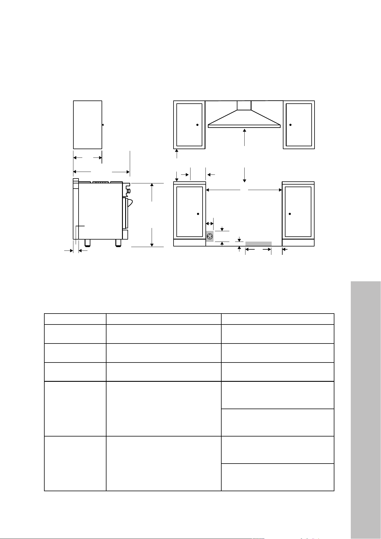
• An agency-approved, properly-sized manual shut-off valve should be installed no
higher than 3" (76 mm) above the floor and no less than 2" (51 mm) and no more than
8" (203 mm) from the right side of the range (facing product).
• To connect gas between shut-off valve and regulator, use an agency-approved, properly
sized flexible or rigid pipe. Check all local code requirements.
INSTALLATION ADJACENT TO KITCHEN CABINETS
• The range may be installed directly adjacent to existing standard countertop cabinet
heights of 36" (914 mm) from the floor.
• For the best look, the range top should be level with the cabinet countertop, depending
on your kitchen layout. This can be accomplished by adjusting the leg height as noted on
“Installing the Legs” on page 13.
• NOTE: The range CANNOT be installed directly adjacent to kitchen walls, tall cabinets,
tall appliances, or other vertical surfaces above 36" (914 mm) high. The minimum side
clearance in such cases is 6" (152 mm).
• Wall cabinets with minimum side clearance must be installed 18" (457 mm)
above the countertop with countertop height between 35 1/2" and 37 1/4"
(901 mm and 946 mm). The maximum depth of wall cabinets above the range shall be
13" (330 mm).
• For cutout depth, the recommendation for all RA models is the standard cabinet depth of
24" (610 mm) so the front face of the oven sticks out from the counter to fully and safely
open the door for optimal use.
• For cutout width between cabinets, the recommendations below are slightly larger than
the actual product widths noted on pages 9–10 and page 16; this allows for
minimal clearance on each side. Kitchen layouts may vary slightly, so adjust accordingly:
• RA24 series ranges: 24" (610 mm)
• RA30 series ranges: 30" (762 mm)
• RA36 series ranges: 36" (914 mm)
• RA48 series ranges: 48" (1219 mm)
• RA60 series ranges: 60" (1524 mm)
WARNING
Do not install ranges in an island configuration. Exposed areas of the range
may become hot and can cause injury.
INSTALLATION
16
Installation Requirements
Cooking Range
13 "
(330 mm)
location of gas
and electrical
extends on floor
36 1/8"–38 5/8"
(919 mm–981 mm)
to cooking
surface
W
opening width
18 "
(457 mm)
6"
(152 mm)
Front ViewSide View
2 3/4" (70 mm)
5 3/4"
(146 mm)
3 1/4" (83 mm)
12 "
(305 mm)
5"
(127 mm)
gas
2"
(51 mm)
27 1/2"
(699 mm)
30"–36" (762 mm–914 mm)
to bottom of
ventilation hood
MINIMUM CUTOUT WIDTH
“W” changes with size of range: 24"–60" (610 mm–1524 mm)
RANGE SIZE EXTERNAL DIMENSIONS* INTERNAL DIMENSIONS
RA24 series ranges
23 7/8" W x 27 1/2" D x 36 1/8" H
(606 mm W x 699 mm D x 918 mm H)
18 1/2" W x 18 1/2" D x 14" H
(470 mm W x 470 mm D x 356 mm H)
RA30 series ranges
29 3/4" W x 27 1/2" D x 36 1/8" H
(756 mm W x 699 mm D x 918 mm H)
26 1/2" W x 18 1/2" D x 14" H
(673 mm W x 470 mm D x 356 mm H)
RA36 series ranges
35 3/4" W x 27 1/2" D x 36 1/8" H
(908 mm W x 699 mm D x 918 mm H)
30 1/2" W x 18 1/2" D x 14" H
(775 mm W x 470 mm D x 356 mm H)
RA48 series ranges
47 3/4" W x 27 1/2" D x 36 1/8" H
(1213 mm W x 699 mm D x 918 mm H)
Small oven:
12 1/2" W x 18 1/2" D x 14" H
(318 mm W x 470 mm D x 356 mm H)
Large oven:
26 1/2" W x 18 1/2" D x 14" H
(673 mm W x 470 mm D x 356 mm H)
RA60 series ranges
59 7/8" W x 27 1/2" D x 36 1/8" H
(1521 mm W x 699 mm D x 918 mm H)
Small oven:
18 1/2" W x 18 1/2" D x 14" H
(470 mm W x 470 mm D x 356 mm H)
Large oven:
30 1/2" W x 18 1/2" D x 14" H
(775 mm W x 470 mm D x 356 mm H)
*Product heights are based on legs being at their lowest settings.
INSTALLATION
17
Power Rating & Electrical Connection
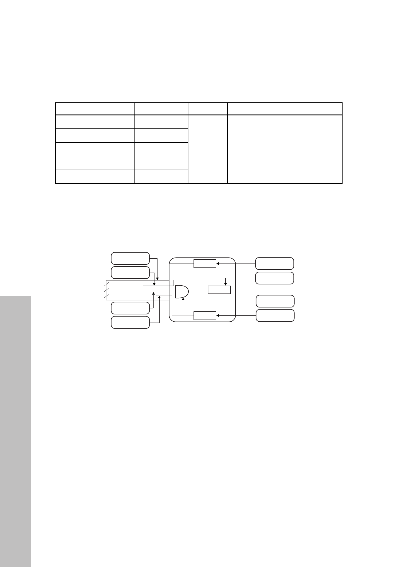
ELECTRIC POWER RATING
RANGE SIZE AMPERAGE VAC PLUG
RA24 series ranges 20 A
240 VAC NEMA 14-50P (50 AMP plug)
RA30 series ranges 15 A
RA36 series ranges 15 A
RA48 series ranges 30 A
RA60 series ranges 40 A
A properly grounded and horizontally-mounted NEMA 14-50P electrical outlet should be
installed in the wall behind the range at least 2" (51 mm) above the floor and not more than
8" (203 mm) from the bottom left side (facing product).
L2 (red)
N (white)
G (green)
L1 (black)
L2 (red)
N (white)
G (green)
L1 (black)
cable from
power supply
Four-Wire Connection
Receptacle
NEMA 14-50R
ELECTRICAL GROUNDING
Our oven is equipped with a four-prong plug for your protection against shock hazard and
should be plugged directly into a properly grounded receptacle. Do not cut or remove the
prong from this plug.
Disconnect electrical power at the circuit breaker box or fuse box before
installing the appliance. Provide appropriate ground for the appliance.
Use copper conductors only. No attempt should be made to operate the
appliance during power failure.
WARNING
INSTALLATION

18
Gas Connection
GAS CONNECTION
• All gas connections must comply with national and local codes. The gas supply line
(service) must be the same size or greater than the inlet line of the appliance. This range
uses a 1/2" (13 mm) NPT inlet. Use appropriate sealant on all pipe joints that are
resistant to gas.
• This range can be used with natural or liquid propane gas. The range is shipped from the
factory for use with natural gas.
• For liquid propane gas household installation, the appliance must be converted by a
factory-trained professional, or qualified licensed plumber or gas service company.
• Gas conversion is important for safe and effective use of the appliance. It is the
responsibility of the owner of the range to perform the appropriate gas conversion
following the directions of the manufacturer.
• The gas conversion procedure is described in this manual and in the package containing
the conversion orifices shipped with every range.
• Please provide the service person with this manual before work is started on the range top.
DO NOT use an open flame when checking for leaks.
WARNING
NOTES:
• Leak testing of the appliance shall be conducted according to the manufacturer’s
instructions.
• Always check for leaks with a soapy water solution or other acceptable method.
• Check for gas leakage on all gas connections between inlet gas pipes of the appliance,
the gas regulator, and the manual shut-off valve. Bubbles will form with a soapy water
solution if there is a leak.
INSTALLATION
19
Gas Connection
INSTALLATION
MANUAL SHUT-OFF VALVE
• This valve is not shipped with the appliance and must be provided by the installer.
• The valve must be installed in the gas service line between the gas hook-up on the wall
and the appliance inlet, in a position where it can be reached quickly in the event of
an emergency.
• In Massachusetts: A T-handle type manual gas shut-off valve must be installed in the gas
supply line to this appliance.
FLEXIBLE CONNECTIONS
• In case of installation with flexible couplings and/or quick-disconnect fittings, the
installer must use a heavy duty, AGA design-certified commercial flexible connector of
at least 1/2" (13 mm) NPT with a suitable strain relief in compliance with ANSI Z21.41
and Z21.69 standards.
• In Massachusetts: The unit must be installed with a 36" (914 mm) flexible gas connector.
• In Canada: Use CAN 1-6, 10-88 metal connectors for gas appliances and CAN 1-6.9,
M79 quick disconnect devices for use with gas fuel.
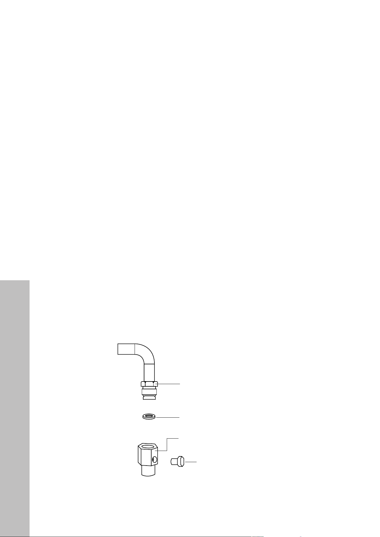
PRESSURE TEST POINT STOPPER VALVE
To avoid gas leaks, the pressure test-point stopper valve and gasket supplied with the range
is already installed on the gas fitting at the back of the range according to the diagram below.
Gas pipe
Gasket
Gas connection adaptor 1/2" NPT with
pressure test point 1/8" NPT (to be fixed
toward external side of the appliance)
Pressure test-point stopper
20
Gas Connection
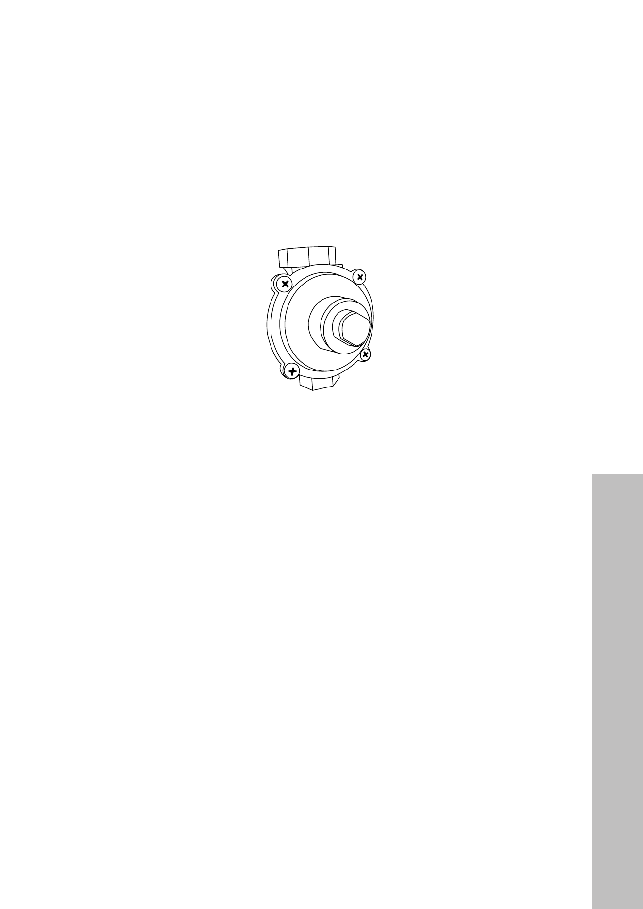
PRESSURE REGULATOR
Since service pressure may fluctuate with local demand, every gas cooking appliance must be
equipped with a pressure regulator on the incoming service line for safe and efficient operation.
•
Pressure Regulator
The pressure regulator shipped with the appliance has two female 1/2" (13 mm) NPT threads.
• The regulator shall be installed properly in order to be accessible when the appliance is
installed in its final position.
• Manifold pressure should be checked with a manometer and comply with the values
indicated below.
• Natural gas — 4" W.C.P. (1 kPa)
• Liquid propane gas — 10" W.C.P. (2.45 kPa)
• Incoming line pressure upstream from the regulator must be 1" W.C.P. (0.25 kPa) higher
than the manifold pressure in order to check the regulator.
• The regulator used on this range can withstand a maximum input pressure of 1/2 psi
(13.8" W.C.P. or 3.4 kPa). If the line pressure exceeds that amount, a step down regulator
is required.
• The appliance, its individual shut-off valve, and the pressure regulator must be disconnected
from the gas line during any pressure testing of that system at pressures in excess of 1/2 psi
(13.8" W.C.P. or 3.4 kPa).
WARNING
Before carrying out this operation, disconnect the appliance from gas and
electricity. Gas conversion shall be conducted by a factory-trained professional.
INSTALLATION
21
Gas Conversion Procedure
INSTALLATION
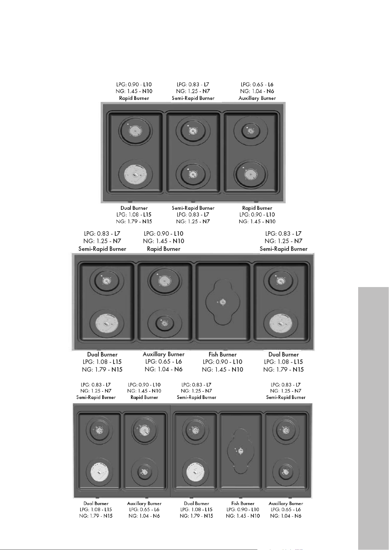
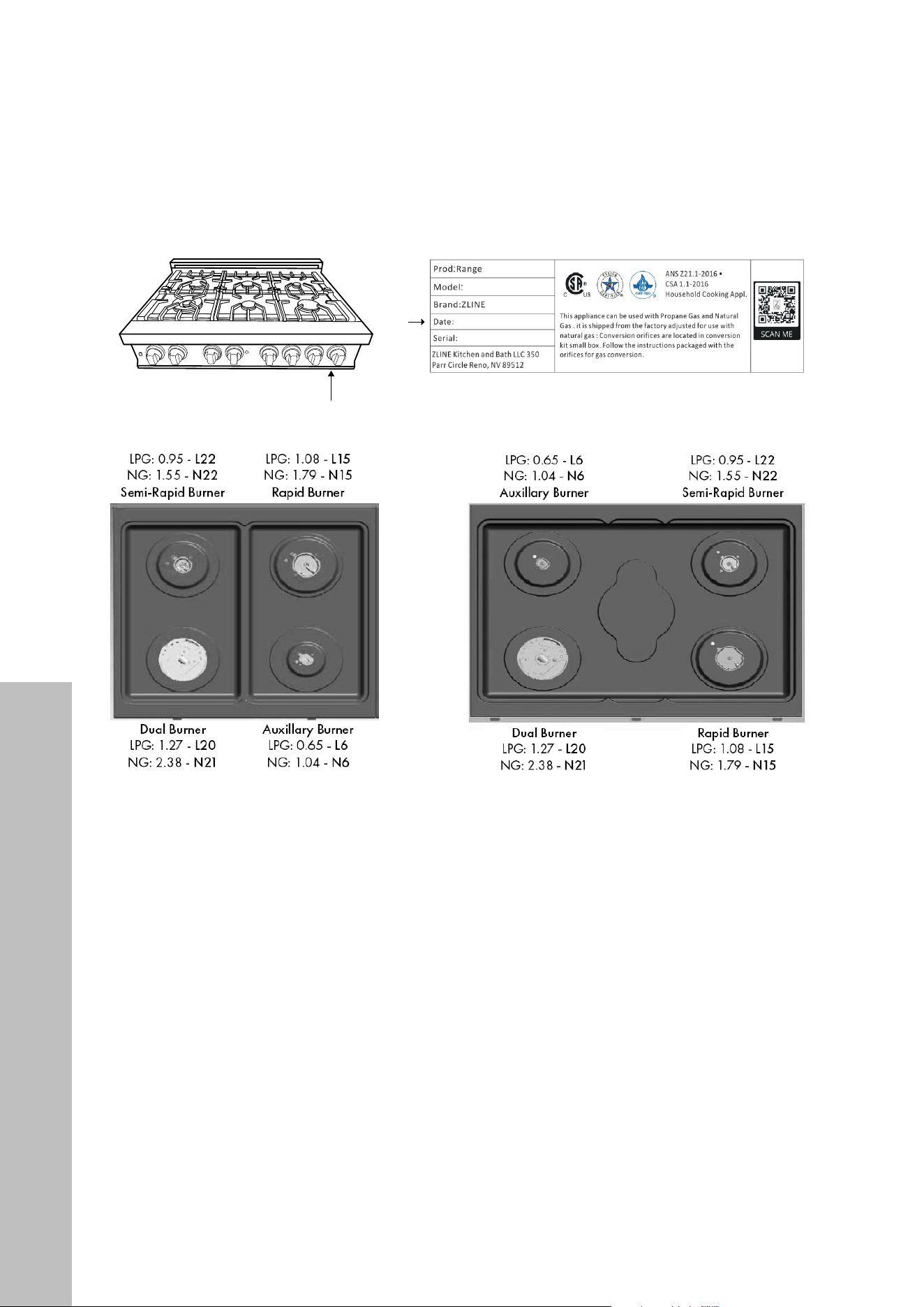
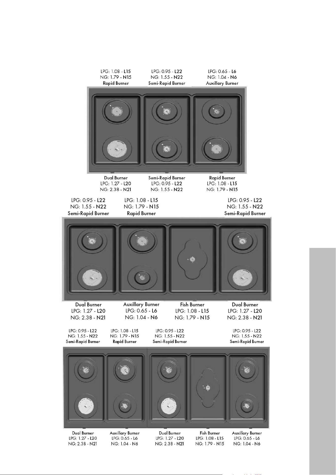
LIQUID PROPANE CONVERSION PROCEDURE
The gas conversion procedure for this range top includes:
1. Pressure Regulator
2. Surface Burners
3. Flame Adjustment
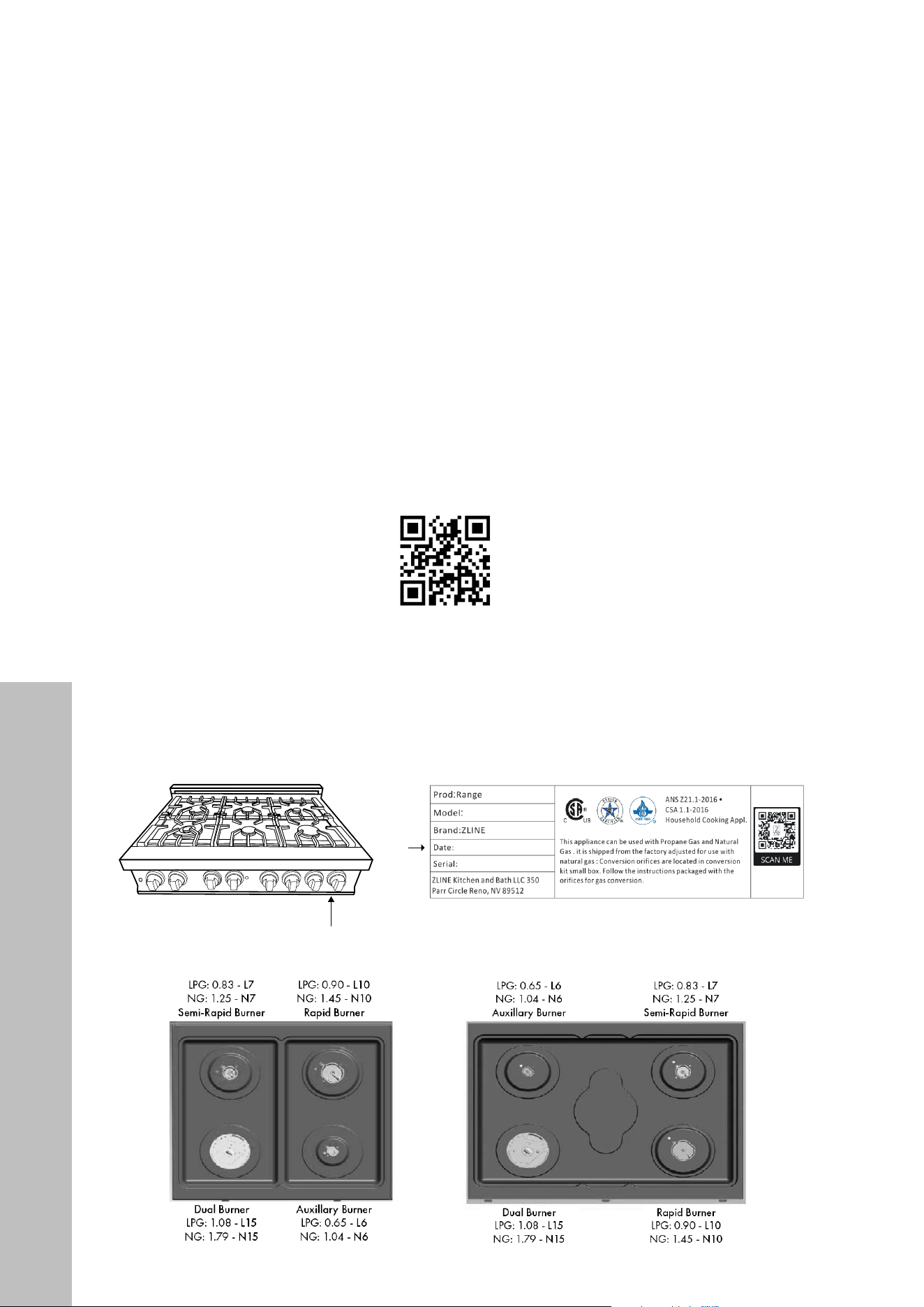
The conversion is not finished if all steps are not completed. Before performing the gas
conversion, locate the package containing the replacement orifices, which has a number
indicating its flow diameter printed on the body. Consult the table below for matching orifices
to burners. Save the orifices removed from the range top for future use.
LPG: Liquid Propane Gas
NG: Natural Gas
Reference the diagrams below if your range was manufactured before May 2021.
To check, reference the rating label under the front edge of the range. In some older
models, the label may be located on the back of the unit.
Example label
Appliance Tag Here
Scan to follow along with a video.
22
Gas Conversion Procedure
INSTALLATION
23
Gas Conversion Procedure
INSTALLATION
Reference the diagrams below if your range was manufactured after May 2021.
To check, reference the rating label under the front edge of the range.
Example label
Appliance Tag Here
24
Gas Conversion Procedure
INSTALLATION
25
Gas Conversion Procedure
INSTALLATION
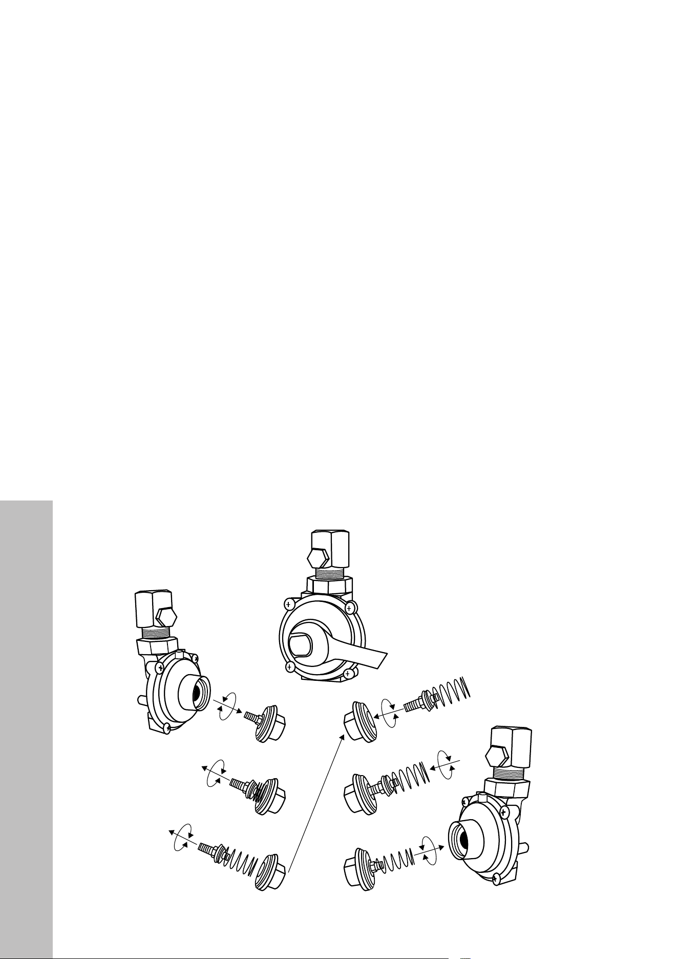
STEP 1: PRESSURE REGULATOR
The pressure regulator supplied with the appliance is a convertible type pressure regulator
for use with natural gas at a nominal outlet pressure of 4" W.C.P. (1 kPa) or liquid propane
gas at a nominal outlet pressure of 10" W.C.P. (2.5 kPa) and it is pre-assembled from the
factory to operate with one of these gas pressures as indicated in the labels affixed on the
appliance, package, and instruction booklet.
To convert the regulator for use with other liquid propane gas:
1. Unscrew the front cap of the regulator (as seen below). Inside the cap is a screw. By
hand, remove the screw to reveal a spring. Invert the screw back into the cap with the
spring on top.
2. With the spring sticking out of the cap, reinstall the cap back onto the regulator.
3. Using a manometer, double check pressure is at 10" W.C.P. (2.5 kPa). If you need to
adjust pressure, screw or unscrew the black spacer where the spring is located.
Any issues related to improper propane conversion are NOT covered
under warranty.
WARNING
5/8" (16 mm)
Reverse regulator
screw and spring.
Gas Conversion Procedure
Liquid Propane Gas
Natural Gas
26
Gas Conversion Procedure
INSTALLATION
STEP 2: SURFACE BURNERS
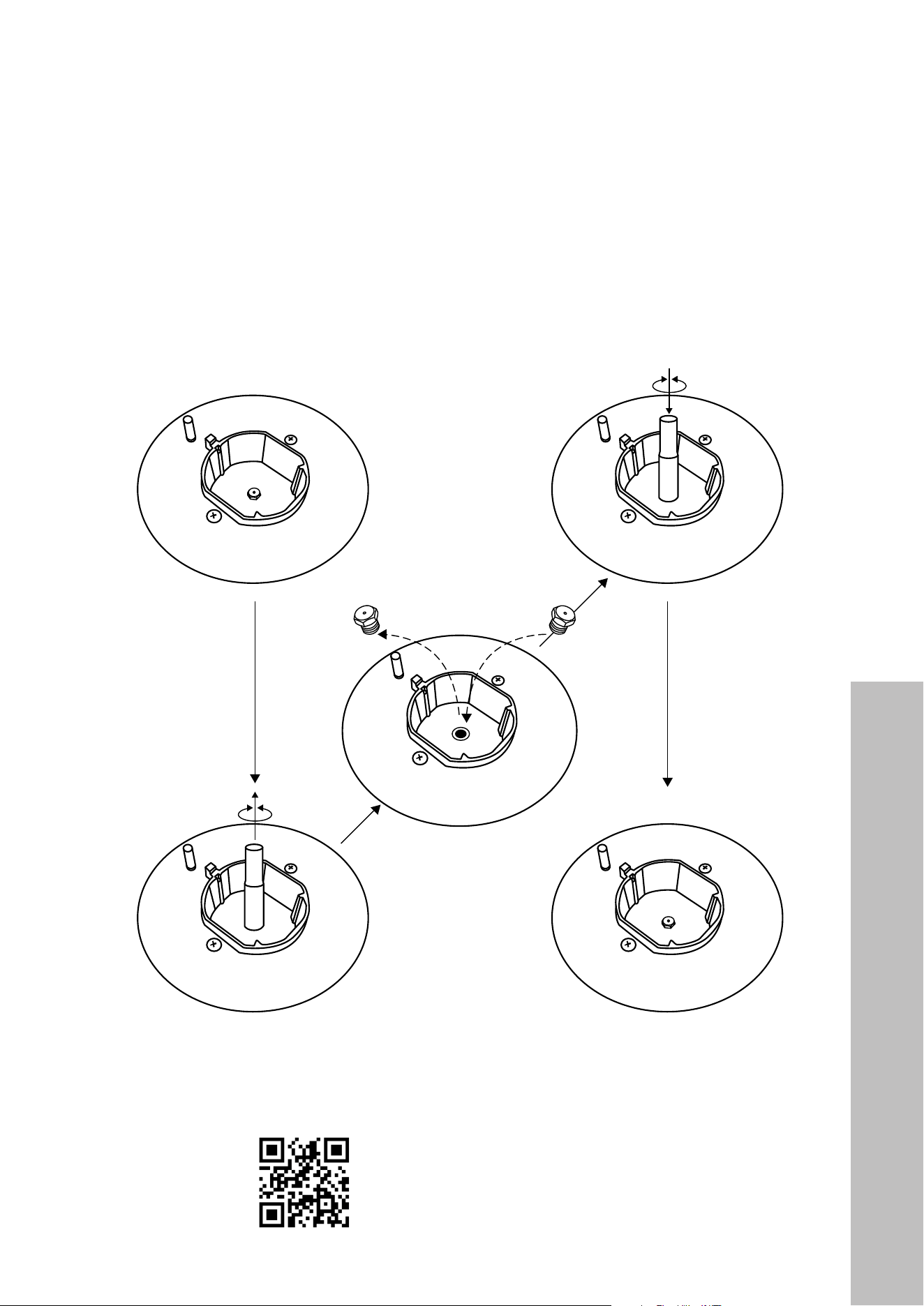
1. To replace the orifices of the surface burners, lift up the burners and unscrew the orifices
shipped with the range using a 7 mm socket wrench.
2. Replace orifices using the conversion set supplied with the range. Each orifice has a
number indicating its flow diameter printed on the body. Consult the tables starting on
page 21 for matching orifices to burners.
NG: Natural Gas
LPG: Liquid Propane Gas
NG LPG
7 mm
7 mm
Step1
Step 2
Step 3
Step 4
Step 5
NOTE: For the dual burner, the orifice is located on the side of the burner. Use a 7 mm
boxed end wrench to remove and tighten.
Scan to follow along with a video.
27
Flame Adjustment
INSTALLATION
STEP 3: FLAME ADJUSTMENT
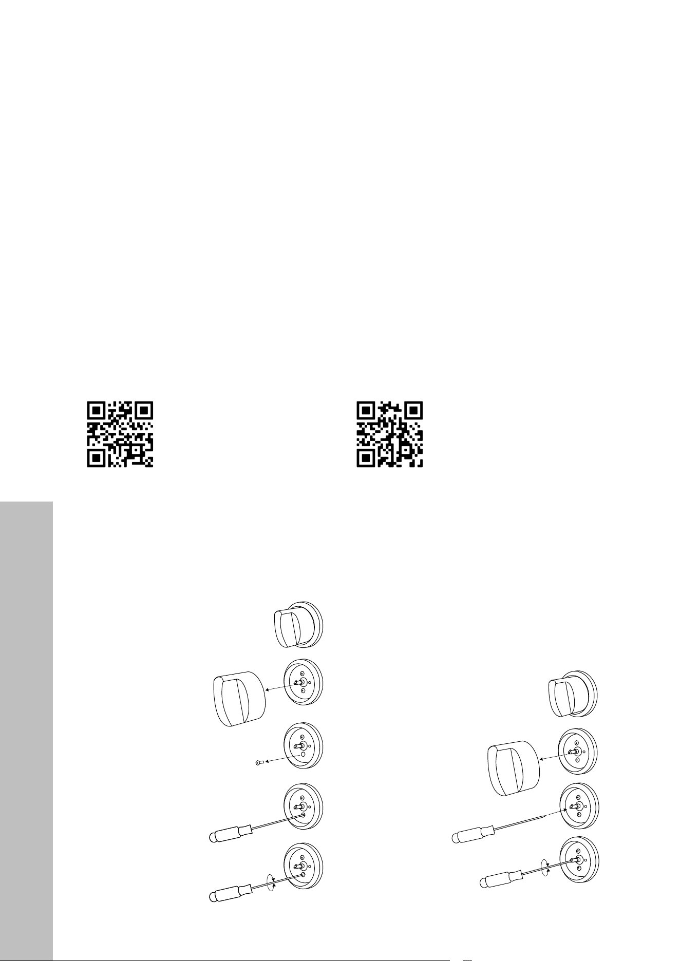
1. Light one burner at a time and set it to the MINIMUM position (small flame).
2. Remove the knob by firmly and carefully pulling it straight out.
3. The range is equipped with a safety valve. Using the 2.0 x 50 mm flat-head screwdriver
provided with this manual, locate the adjustment screw (see diagram below), hold the
metal stem with one hand and turn the screwdriver to the right or left until the burner
flame is adjusted to desired minimum.
4. Make sure that the flame does not go out when switching quickly from the MAXIMUM
to the MINIMUM position.
The high flame setting cannot be adjusted to be lower. If the height is too high, revisit the
conversion set-up. A step may have been missed.
Reference the diagrams
below if your range top was
manufactured before May
2021. To check, reference
the rating label under the
front edge of the range.
Scan the QR code to follow
along with a video.
WIRING DIAGRAM
DW7714-18 & DW7713-24
18” & 24“ Panel-Ready Dishwasher
0.0.0.
FLAME ADJUSTMENT
Germania
RA series, RG series
zlinekitchen.com 1-614-777-5004 0.0.0.zlinekitchen.com 1-614-777-5004
2.0 x 50 mm
2.0 x 50 mm
If the customer flame control valve looks like this (left), then they will not be able to adjust the
flame without removing one of the screws. These new ranges are already fielded, so please
do not process returns for this issue. The valves are different from the previous ones and are
not interchangeable.
Reference the diagrams
below if your range top was
manufactured after May
2021. To check, reference
the rating label under the
front edge of the range.
In some older models, the
label may be located on the
back of the unit. Scan the
QR code to follow along
with a video.
2.0 x 50 mm
2.0 x 50 mm
Flame Adjustment

28
Installation Checklist
INSTALLATION
INSTALLATION CHECKLIST
1. Is the range mounted on its legs and is the unit level?
2. Is the back guard securely connected?
3. Have the chains been properly installed?
4. Does the clearance from the side cabinets comply with the manufacturer’s direction?
5. Is the electricity properly grounded to a dedicated NEMA 14-50P receptacle?
6. Is the gas service line connected following the directions of the manufacturer?
7. Have all the proper valves, stoppers, and gaskets been installed between the range and
the service line?
8. Has the gas connection been checked for leaks?
9. Has the range been set up for the type of gas available in the household (liquid propane
gas or natural gas)?
10. Does the flame appear sharp blue with no yellow tipping?
11 . Has the minimum setting for all burners been adjusted?
12. Have the range top flames been adjusted to customer preference?
13. Are the oven burners/elements installed properly and functioning?
FINAL PREPARATION
• All stainless steel body parts should be wiped with hot, soapy water and with a stainless
steel cleanser.
• If build-up occurs, do not use steel wool, abrasive cloths, cleaners, or powders. If it is
necessary to scrape stainless steel to remove encrusted materials, soak with hot, wet
cloths to loosen the material, and then use a wood or nylon scraper. DO NOT use a
metal knife or any other metal tool to scrape stainless steel.
• Before using the oven for food preparation, clean thoroughly with a warm soap and
water solution to remove film residues and any dust or debris from installation, then rinse
and wipe dry.

WARRANTY
COVERAGE
ZLINE Kitchen and Bath (“ZLINE”) dual fuel ranges have a one year parts and service warranty
and a limited lifetime warranty on burners, which includes parts and labor for spark tips.
ZLINE warranty periods begin from the original date of product delivery and solely cover the
original purchaser of the product, delivered new and in its original carton. The limited warranty
covers all parts and labor for necessary repairs if any part of the product, or the product itself,
proves to be defective in materials or workmanship. The product must be deemed serviceable
via troubleshooting with the ZLINE Customer Experience team. All service on ZLINE products
under warranty must be performed by ZLINE-approved and ZLINE-certified service providers
unless otherwise specified by ZLINE. Service will be provided during normal business hours.
Products must be unobstructed and accessible to the service provider at the time of service.
ZLINE’s liability is limited to the original purchase price of the product. Additional injuries,
losses, damages, or other inconveniences caused by product malfunction or defects in materials
are not covered under the terms of this warranty.
TERMS
ZLINE warranties apply only to the original purchaser of a ZLINE product installed for normal
residential use. This is defined as a single-family, residential dwelling in a non-commercial
setting. Any warranty claim stemming from installation, operation, or any other use within a
commercial setting is not covered under this limited warranty. Commercial settings include,
but are not limited to: schools, churches, hotels, restaurants, vacation rentals such as Airbnb,
daycare centers, private clubs, fire stations, common areas in multi-family dwellings, nursing
homes, food service locations, and institutional food service locations such as hospitals or
correctional facilities.
This warranty is non-transferable and will not under any circumstance be extended based on
the date of installation — the warranty period takes effect from the date of delivery and only
covers the original purchaser. The warranty applies only to products installed in the contiguous
United States and the District of Columbia. Failure to secure certified warranty service per
these terms will result in a forfeiture of the remaining warranty. Out-of-pocket payments will not
be reimbursed unless prior approval is received from ZLINE and/or ZLINE-certified service
contract partners. Unapproved out-of-pocket payments for service will not be reimbursed. All
warranty procedures must be followed to maintain warranty coverage.

WARRANTY
If a product qualifies within the service window provided under these warranty terms, and ZLINE
is unable to repair the product or a defective part of the product after a reasonable number
of attempts, ZLINE reserves the right to offer to replace the defective part or the product or
provide the original purchaser a full refund of the purchase price of the product (not including
installation, removal, or other charges that were not included in the original purchase price).
The original purchaser of the product must provide the original proof of purchase, including the
purchase date, when filing a claim to obtain replacement parts, service, or refunds. Additionally,
the original purchaser of the product must provide the serial number of the product when filing
a claim to obtain replacement parts, service, or refunds.
This warranty shall not apply to any ZLINE product in which the original factory serial
number has been removed, altered, or cannot be readily determined for any reason. Further,
ZLINE is not responsible for damage resulting from, but not limited to: shipment, delivery, or
improper installation; negligence or improper maintenance, misuse, or abuse of the product;
unauthorized alteration, modification, or tampering with the product; accident, fire, floods,
pest infestations, pandemics, natural disasters, or any other unpreventable or unexplained
acts of nature, commonly referred to as “acts of God”; flare-up fires or damages caused by
improper electric supply, electrical line current, voltage, or power surges; and service to correct
installation not in accordance with the instructions contained in ZLINE’s product manuals and/
or with local government codes.
This warranty does not apply to aesthetic damage, scratches, or natural wear caused by normal
use; second-hand, open box products, or products purchased from an unauthorized retailer;
improper liquid propane gas conversion or damage related to improper liquid propane gas
conversion; burner flame adjustments or related complaints; corrections regarding normal
adjustments or settings or local gas supply issues resulting in low pressure or other issues;
damages or issues stemming from alteration or tampering with the range, including, but not
limited to, painting any portion of the product’s interior or exterior and cutting the supplied
power cord to manually hardwire the product; and service for gas pressure issues related to
installation at high altitudes. A high-altitude pressure regulator must be sourced by the customer.
In the event service is dispatched, and it is discovered that the reported issue is not covered
under warranty based on the disclaimers above, the customer will be responsible for all service
fees. Failure to pay these fees will result in the forfeiture of remaining warranty coverage.
WARRANTY
Information contained within ZLINE’s installation and user manuals, in addition to product
information included on ZLINE’s website and all related digital listings, do not cover every
possible condition and situation that may occur during the installation or operation of
ZLINE products.
ZLINE reserves the right to make changes at any time to its products when considered safe,
necessary, and useful. Always check the ZLINE website for the most up-to-date version of its
product manuals: www.zlinekitchen.com/pages/manuals.
Do not install or operate any ZLINE product if it has missing or broken parts or if it arrives
damaged due to shipping. If ZLINE products arrive damaged, contact ZLINE Customer
Experience at 1-614-777-5004 for help. Failure to report a damaged appliance prior to
installation or operation may void the warranty.
ZLINE disclaims responsibility for damage or injury caused by improper installation or use of
any of its products. ZLINE is under no obligation, by law or otherwise, to provide concessions,
including repairs, prorates, rebates, discounts, or replacements, once the warranty has expired.
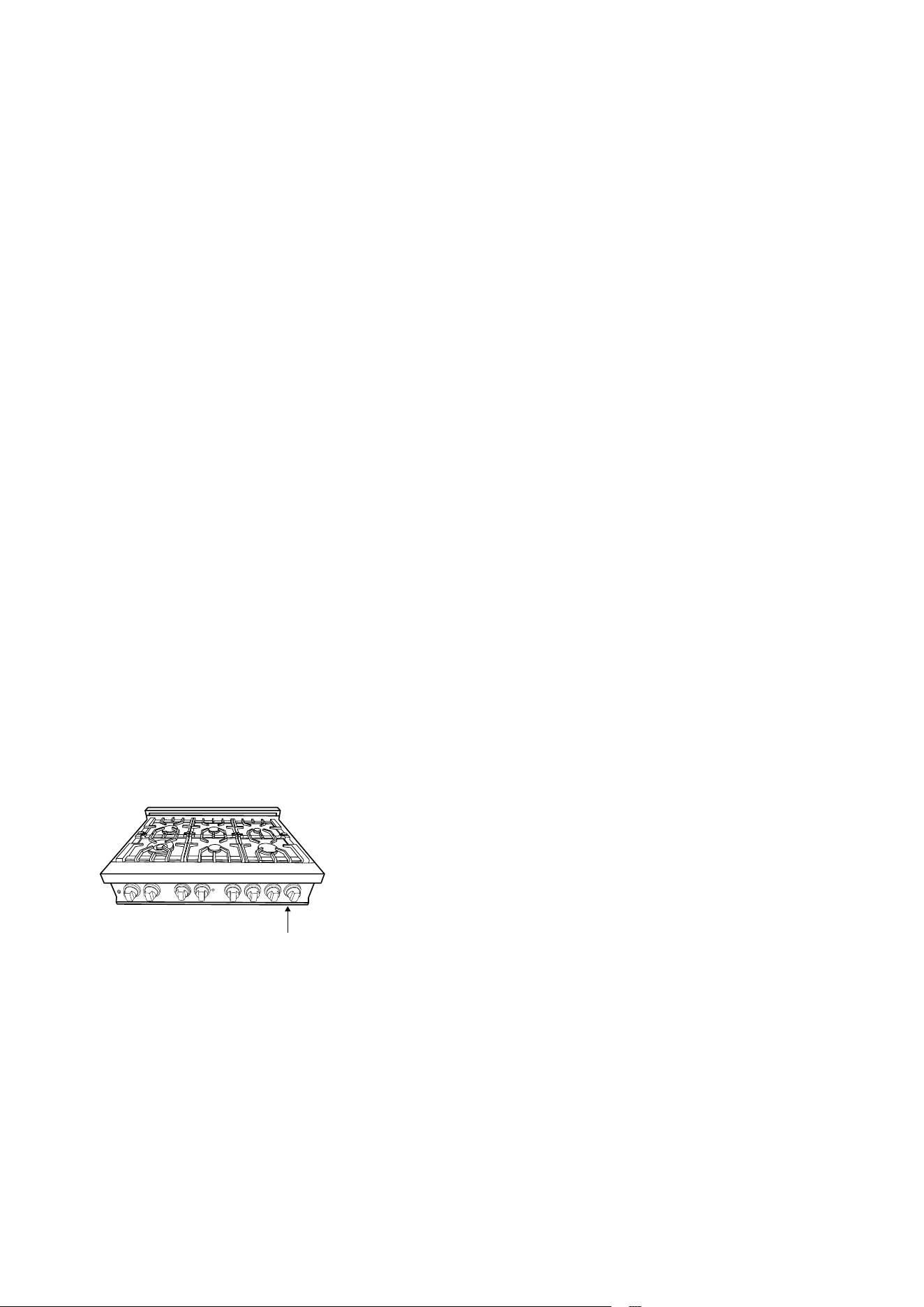
SERIAL NUMBER LOCATION
Appliance Tag Here
Please write down the model number and serial number of
your appliance. Both numbers are located on the rating tag
located under the front edge of the range top. Do not remove
permanently affixed labels, warnings, or plates from the
product. This will void the warranty. You may also consider
attaching your receipt or proof of purchase to this manual.

SERVICE
For warranty service, please contact our Customer Service team at
1-614-777-5004 or visit www.zlinekitchen.com/contact to utilize our
online Customer Experience Portal.
Scan the QR code to view the most up-to-date version of our Installation
Manual and User Manual.
Need to purchase a part or accessory for your ZLINE product?
Visit www.zlineparts.com, ZLINE’s official parts distribution partner.
WARRANTY