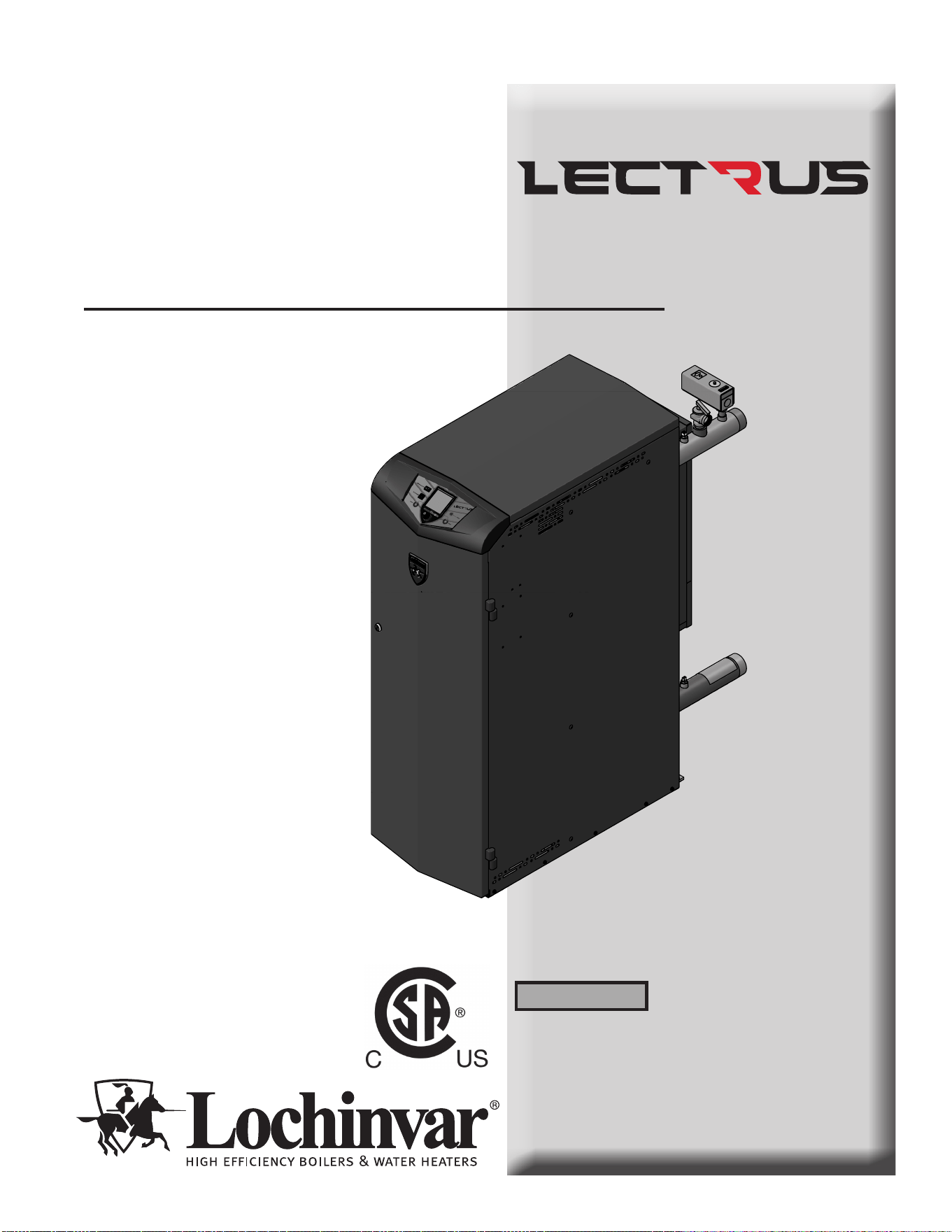
Installation & Operation Manual
Models: KEB0015 - KEB0150
is manual must only be used by a
qualied heating installer / service
technician. Read all instructions,
including this manual and the
Lectrus Service Manual, before
installing. Perform steps in the order
given. Failure to comply could result
in severe personal injury, death, or
substantial property damage.
⚠ WARNING
Save this manual for future reference.
100376295_2000786840_Rev K
TM
2000659627 01

2
Contents
Hazard denitions
e following dened terms are used throughout this manual to bring attention to the presence of hazards of various risk levels
or to important information concerning the life of the product.
⚠ DANGER
⚠ WARNING
⚠ CAUTION
CAUTION
NOTICE
DANGER indicates an imminently hazardous situation which, if not avoided, will result in death or serious
injury.
WARNING indicates a potentially hazardous situation which, if not avoided, could result in death or serious
injury.
CAUTION indicates a potentially hazardous situation which, if not avoided, may result in minor or moderate
injury.
CAUTION used without the safety alert symbol indicates a potentially hazardous situation which, if not
avoided, may result in property damage.
NOTICE indicates special instructions on installation, operation, or maintenance that are important but not
related to personal injury or property damage.
HAZARD DEFINITIONS .................................................. 2
PLEASE READ BEFORE PROCEEDING ..................... 3
THE LECTRUS -- HOW IT WORKS ............................ 4-5
RATINGS ........................................................................... 6
PRODUCT SUMMARY .................................................... 7-8
1. DETERMINE BOILER LOCATION
Provide Air Openings to Room ..................................... 9-10
Flooring and Foundation .................................................. 11
2. PREPARE BOILER
Remove Boiler from Wood Pallet ..................................... 12
3. HYDRONIC PIPING
System Water Piping Methods ......................................... 13
Low Water Cuto Device .................................................. 13
Chilled Water System ........................................................ 13
Freeze Protection Fluids ................................................... 13
Corrosive Contaminants and Sources ............................. 13
General Piping Information ............................................... 14
Relief Valve Installation .................................................... 14
Near Boiler Piping Components ........................................ 15
Circulator Sizing ................................................................ 15
Near Boiler Piping Connections ...................................16-18
Piping Diagrams .....................................................21-26
4. FIELD WIRING
Line Voltage Connections ................................................ 27
Low Voltage Connections ................................................. 27
Wiring of the Cascade ..................................................26-29
5. STARTUP ................................................................36-43
6. OPERATING INFORMATION
General ............................................................................. 44
Cascade ............................................................................ 48
Sequence of Operation ................................................49-51
Lectrus Control Module ..................................................... 52
Status Display Screens ................................................53-54
7. MAINTENANCE
Maintenance and Annual Startup ..................................... 53
8. DIAGRAMS
Wiring Diagram ...................................................... 59-64
Ladder Diagram ...................................................... 65-67
Revision Notes .................................................. Back Cover
Installation & Operation Manual
Please read before proceeding
Installer – Read all instructions, including
this manual and the Lectrus Service
Manual, before installing. Perform steps in
the order given.
User – is manual is for use only by
a qualified heating installer/service
technician. Refer to the User’s Information
Manual for your reference.
Have this boiler serviced/inspected by
a qualied service technician, at least
annually.
Failure to comply with the above could
result in severe personal injury, death, or
substantial property damage.
Failure to adhere to the guidelines on this
page can result in severe personal injury,
death, or substantial property damage.
When servicing boiler –
• To avoid electric shock, disconnect electrical supply
before performing maintenance.
• To avoid severe burns, allow boiler to cool before
performing maintenance.
Boiler operation –
• Should overheating occur do not turn o or disconnect
electrical supply to circulator. Instead, shut o power to
the boiler only.
• Do not use this boiler if any part has been under water.
e possible damage to a ooded appliance can be
extensive and present numerous safety hazards. Any
appliance that has been under water must be replaced.
Boiler water –
• oroughly ush the system to remove debris. Use
an approved pre-commissioning cleaner (see Start-Up
Section), without the boiler connected, to clean the system
and remove sediment. e pressure vessel can be
damaged by build-up or corrosion due to sediment.
NOTE: Cleaners are designed for either new systems or
pre-existing systems. Choose accordingly.
Freeze protection uids –
• NEVER use automotive antifreeze. Use only inhibited
propylene glycol solutions, which are specically
formulated for hydronic systems. Ethylene glycol is
toxic and can attack gaskets and seals used in hydronic
systems.
Grounding Instructions –
• is boiler must be grounded in accordance with
the National Electrical Code and/or local codes. ese
must be followed in all cases. Failure to ground this
boiler properly may also cause erratic control system
operation on ELECTRONIC CONTROL.
• is boiler must be connected to a grounded metal,
permanent wiring system, or an equipment grounding
conductor must be run with the circuit conductors and
connected to the equipment grounding terminal or lead
on the boiler.
When calling or writing about the boiler
– Please have the boiler model and serial
number from the boiler rating plate.
Consider piping and installation when
determining boiler location.
Any claims for damage or shortage in
shipment must be led immediately
against the transportation company by the
consignee.
Factory warranty (shipped with unit) does
not apply to units improperly installed or
improperly operated.
3
If the information in this manual is not
followed exactly, a re or explosion may
result causing property damage, personal
injury, or loss of life.
is appliance MUST NOT be installed in
any location where gasoline or ammable
vapors are likely to be present.
⚠WARNING
NOTICE
⚠WARNING
⚠WARNING
⚠WARNING
DO NOT install units in rooms or
environments that contain corrosive
contaminants (see Table 3A on page 11).
Failure to comply could result in severe
personal injury, death, or substantial
property damage.
TM

4
The Lectrus - How it works...
1. Steel ASME rated pressure vessel
Allows system water to ow around specially designed
immersion heating elements for maximum heat transfer.
2. Boiler outlet temperature sensor (limit rated)
is sensor monitors boiler outlet water temperature
(system supply). If selected as the controlling sensor,
the control module adjusts boiler element power, so
the outlet temperature is correct.
3. Boiler inlet temperature sensor
is sensor monitors return water temperature (system
return). If selected as the controlling sensor, the control
module adjusts the boiler element power, so the inlet
temperature is correct.
4. Manual Reset High Limit (MRHL)
Immersion-type device for limiting the temperature of
liquids in the boilers. e MRHL can be adjusted for eld
test and is equipped with a reset button.
5. Electronic LCD display
e display features a high-resolution liquid crystal screen,
four (4) buttons, and a navigation dial. A serial and USB
port support additional communication with the control.
6. Water outlet (system supply)
A 2" NPT water connection that supplies hot water to the
system.
7. Water inlet (system return)
A 2" NPT water connection that returns water from the
system to the pressure vessel.
8. SMART SYSTEM Boiler Integrated Control (BIC)
e SMART SYSTEM Control responds to internal and
external signals to meet heating demand.
9. High voltage junction box
e junction box contains the connection points for the
line voltage power.
10. Boiler drain connection
A 3/4" NPT drain connection is provided for easy access in
the event the boiler needs to be drained.
11. Connection board
e connection board provides easy access for connecting
external low voltage devices and pumps.
12. Wiring connections (knockouts)
Conduit connection points for the low voltage and pump
connection boards.
13. Inspection opening
Opening with a 3" NPT brass plug at the bottom of the
boiler tank for easy inspection.
14. Relief valve
Protects the pressure vessel from an over pressure
condition. e relief valve provided with the unit is set at
50 PSI.
15. Line voltage wiring connection points
Add knockouts for the eld installed high voltage.
16. Front panel
Removable panel to gain access to the internal components.
17. Power switch
Turns 120 VAC ON/OFF to the boiler.
18. Transformer
e transformer provides 24VAC power to the low water
cut-o board.
19. High limit sensor (housed with the outlet temperature
sensor)
Device that monitors the outlet water temperature. If the
temperature exceeds its setting, the integrated control will
break the control circuit, shutting the boiler down.
20. Low water cuto probe (LWCO)
Protects the pressure vessel from overheating, by ensuring
adequate water is supplied to the boiler. In the event of
inadequate water levels, the boiler will shut down.
21. Reset switch
Reset switch for the low water cuto. Hold the switch for 10
seconds to reset.
22. Test switch
e test switch permits manual triggering of the LWCO
safety circuit to test the contacts and evaluate the integrity
of the circuit. Hold the switch for 10 seconds to test.
23. Transformer (Control)
e transformer provides 120VAC to the integrated control
and other sub system.
24. Modulation control board (MCB)
e module ne-tunes the energy given to the triac(s) for
linear control of the boiler. It controls the element banks
and in what order they are activated.
25. Top cover
Allows access to the elements, the LWCO probe, the air
purge, and the triacs.
26. Electric elements
ey are activated depending on the demands. Quantity
depends on the model.
27. Triac boards
A board that translates a low voltage signal to increase or
decrease the power to an element.
28. Safety monitor relay
e relay is controlled by the Boiler Integrated Control
(BIC) and provides another layer of safety to disconnect all
the power going to the elements when a fault is active.
29. R6 LWCO Relay
e relay enables the LWCO when a heat demand is active.
*For factory installed options, consult the Lectrus Service
Manual.
Installation & Operation Manual
TM
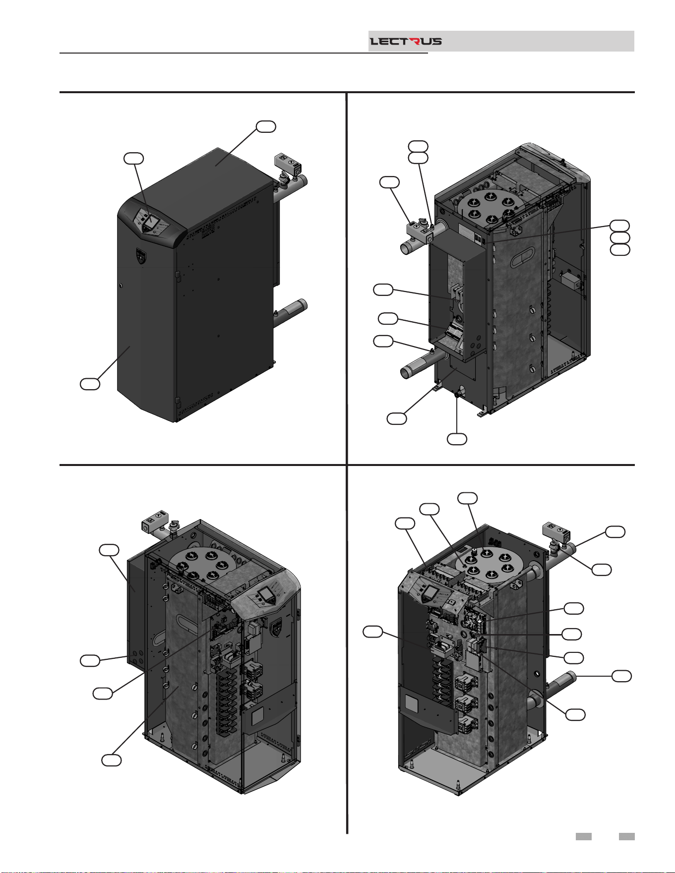
Front View
Left Side (inside unit)
Right Side (inside unit)
The Lectrus - How it works... (continued)
Rear View
5
Models 0015 - 0150
Installation & Operation Manual
TM
2000659627 01
5
25
16
2000659638 01
10
13
3
11
15
4
19
2
17
21
22
2000659645 01
9
12
8
1
2000659628 01
23
27
20
26
14
6
24
18
29
28
7
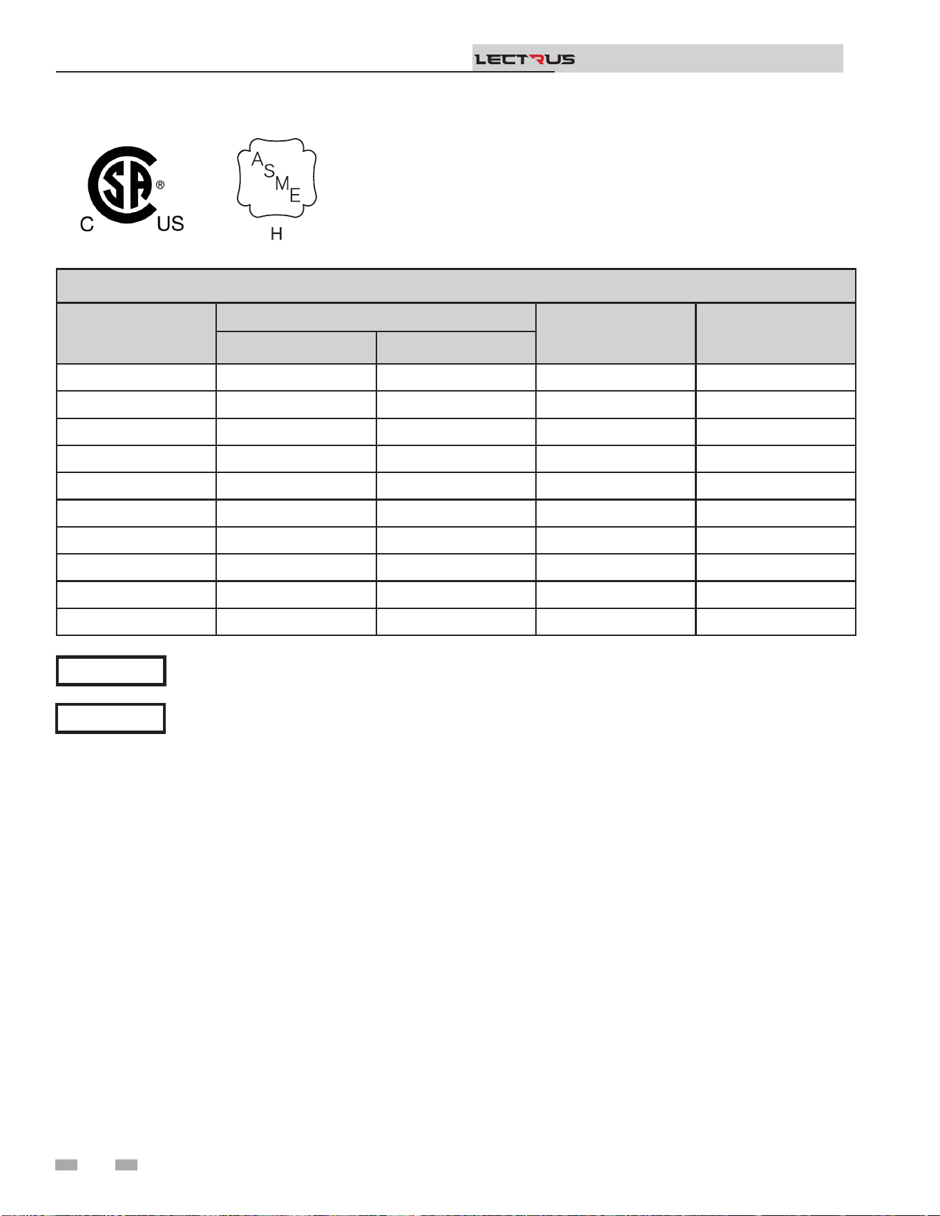
Ratings
Note:
Lectrus boilers comply with the requirements of CSD-1
Section CW-400 requirements as a temperature operation
control. e manual reset high limit provided with the Lectrus
is listed to UL 60730-1 and UL 60730-2-9.
6
Maximum allowed working pressure is
located on the rating plate.
For all wiring connections, please refer to
Table 4A.
NOTICE
NOTICE
Installation & Operation Manual
TM
LECTRUS BOILER SPECIFICATIONS
Model
Input KW
Boiler Water
Content (Gal)
Water
Connections
Min Max
KEB0015- 0.8 15 17.6 2"
KEB0030- 0.8 30 17.6 2"
KEB0045- 0.8 45 17.6 2"
KEB0060- 0.8 60 17.6 2"
KEB0075- 0.8 75 17.6 2"
KEB0090- 1.6 90 17.6 2"
KEB0105- 1.6 105 32 2"
KEB0120- 1.6 120 32 2"
KEB0135- 1.6 135 32 2"
KEB0150- 1.6 150 32 2"
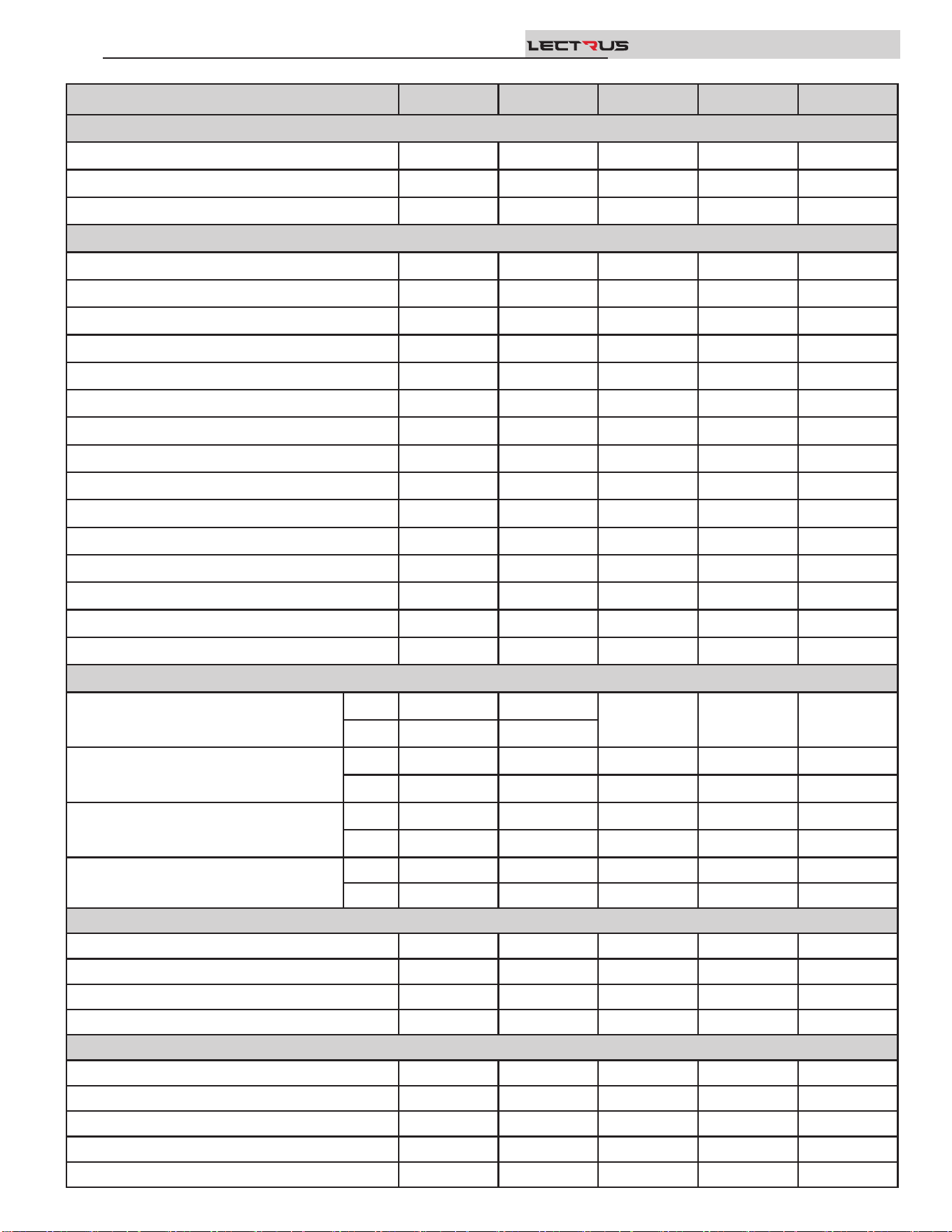
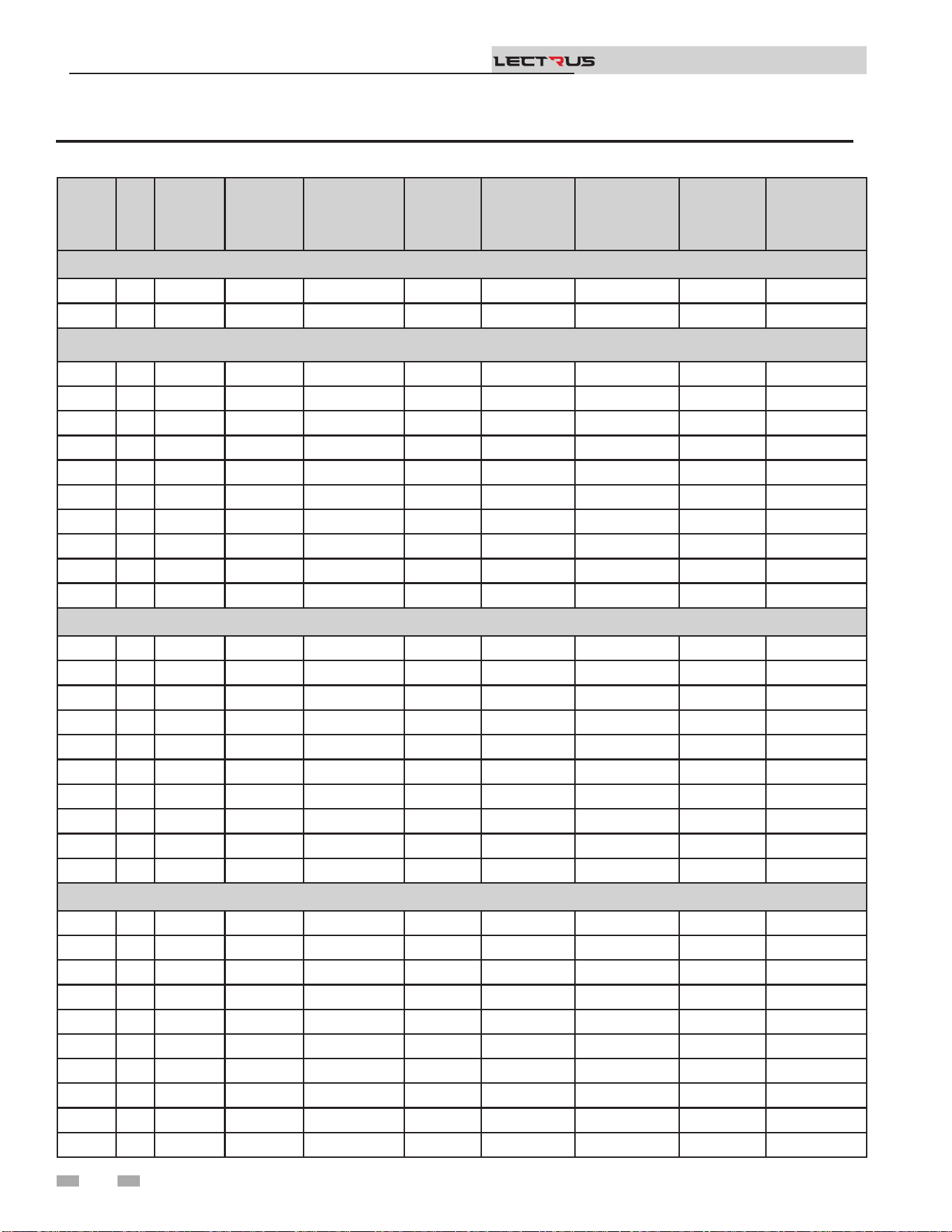
PRODUCT SUMMARY
KEB0015 KEB0030 KEB0045 KEB0060 KEB0075
PERFORMANCE
KW 15 30 45 60 75
BTU/H HEATING 51,180 102,360 153,540 204,720 255,900
ELEMENT QUANTITY 1 2 3 4 5
WATER
GALLON CAPACITY 17.6 17.6 17.6 17.6 17.6
INLET CONNECTION 2" NPT 2" NPT 2" NPT 2" NPT 2" NPT
OUTLET CONNECTION 2" NPT 2" NPT 2" NPT 2" NPT 2" NPT
DRAIN 3/4" NPT 3/4" NPT 3/4" NPT 3/4" NPT 3/4" NPT
MAXIMUM FLOW RATE (GPM) 105 105 105 105 105
ABSOLUTE MINIMUN FLOW RATE (GPM) 1.3 1.3 1.3 1.3 1.3
20⁰ ∆T WATER FLOW (GPM) 5.4 11 16 21.9 27.1
HEAD LOSS (FT. OF HD.) 3.3 3.4 3.5 3.7 3.9
40⁰ ∆T WATER FLOW (GPM) 2.4 4.7 7.9 10.8 13.1
HEAD LOSS (FT. OF HD.) 3.6 3.6 3.6 3.7 3.8
Max. WORKING PRESSURE PSI 160 160 160 160 160
# OF RELIEF VALVES 1 1 1 1 1
RELIEF VALVE SIZE 3/4" 3/4" 3/4" 3/4" 3/4"
RELIEF VALVE RATING (MBH) 697 697 697 697 697
RELIEF VALVE PRESSURE RATING (PSI) 50 50 50 50 50
ELECTRICAL
240V - 1PH
FLA
63 125
N/A N/A N/A
MCA
79 157
208V - 3PH
FLA
42 84 125 167 209
MCA
52 105 157 209 261
480V - 3PH
FLA
18 37 55 73 91
MCA
23 46 68 91 113
600V - 3PH
FLA
15 29 44 58 73
MCA
18 37 55 73 91
DIMENSIONS
HEIGHT
47 47 47 47 47
WIDTH
16.75 16.75 16.75 16.75 16.75
DEPTH
41 41 41 41 41
SHIPPING WEIGHT (lbs.)
367 367 367 367 367
MINIMUM SERVICE CLEARANCES
FRONT
36" 36" 36" 36" 36"
REAR
36" 36" 36" 36" 36"
RIGHT SIDE
3" 3" 3" 3" 3"
LEFT SIDE
3" 3" 3" 3" 3"
TOP
32" 32" 32" 32" 32"
Installation & Operation Manual
TM
Installation & Operation Manual
TM
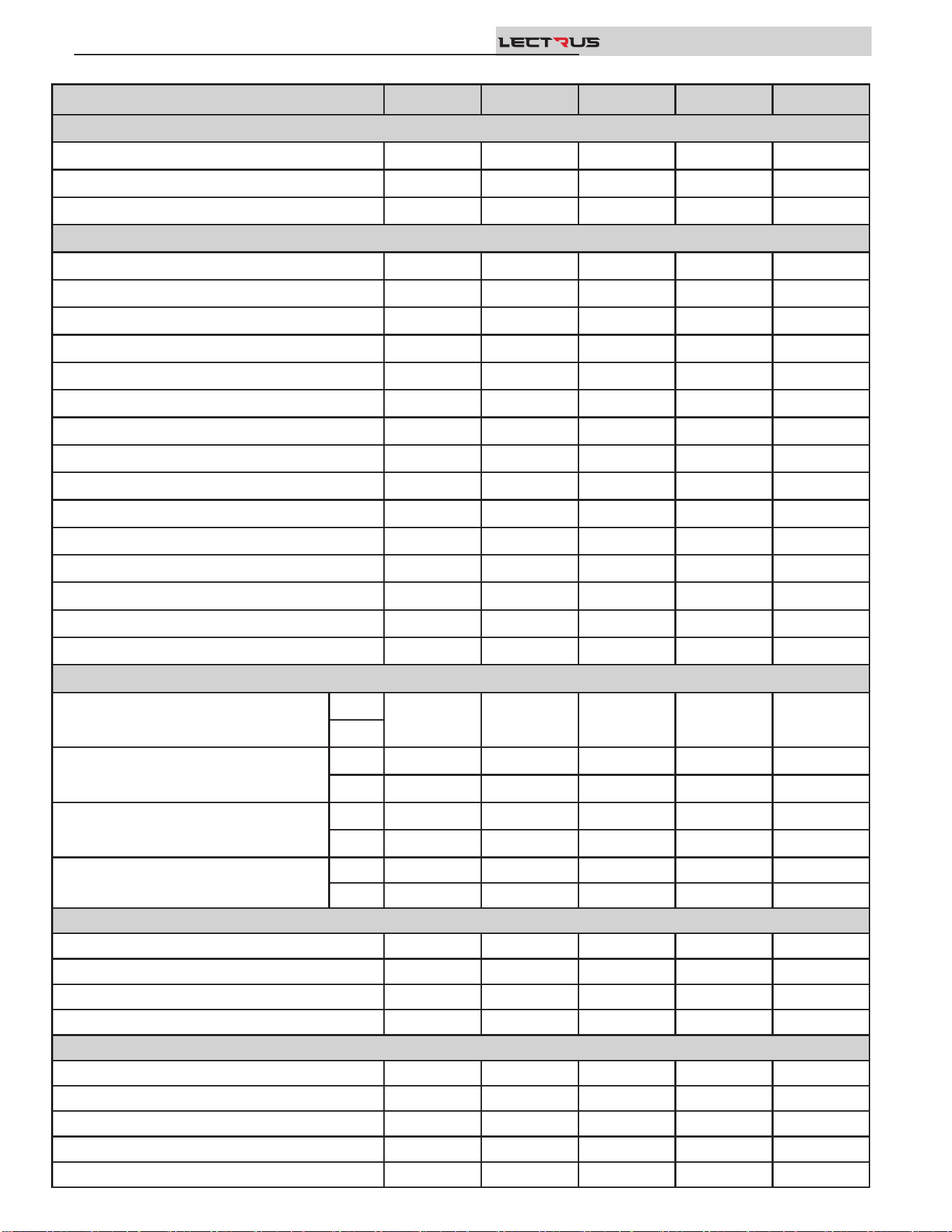
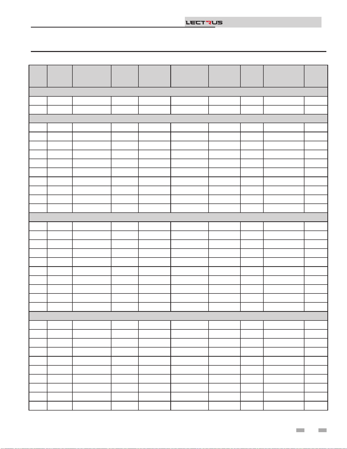
KEB0090 KEB0105 KEB0120 KEB0135 KEB0150
PERFORMANCE
KW 90 105 120 135 150
BTU/H HEATING 307,080 358,260 409,440 460,620 511,800
ELEMENT QUANTITY 6 7 8 9 10
WATER
GALLON CAPACITY 17.6 32 32 32 32
INLET CONNECTION 2" NPT 2" NPT 2" NPT 2" NPT 2" NPT
OUTLET CONNECTION 2" NPT 2" NPT 2" NPT 2" NPT 2" NPT
DRAIN 3/4" NPT 3/4" NPT 3/4" NPT 3/4" NPT 3/4" NPT
MAXIMUM FLOW RATE (GPM) 105 105 105 105 105
ABSOLUTE MINIMUN FLOW RATE (GPM) 2.6 2.6 2.6 2.6 2.6
20⁰ ∆T WATER FLOW (GPM) 32.7 37 41.6 45.7 52
HEAD LOSS (FT. OF HD.) 4.1 4.3 4.4 4.7 5.1
40⁰ ∆T WATER FLOW (GPM) 16 18.9 20.8 23.8 26.1
HEAD LOSS (FT. OF HD.) 3.9 3.9 3.8 4.0 4.3
Max. WORKING PRESSURE PSI 160 160 160 160 160
# OF RELIEF VALVES 1 1 1 1 1
RELIEF VALVE SIZE 3/4" 3/4" 3/4" 3/4" 3/4"
RELIEF VALVE RATING (MBH) 697 697 697 697 697
RELIEF VALVE PRESSURE RATING (PSI) 50 50 50 50 50
ELECTRICAL
240V - 1PH
FLA
N/A N/A N/A N/A N/A
MCA
208V - 3PH
FLA
250 292 334 375 417
MCA
313 365 417 469 521
480V - 3PH
FLA
109 127 145 163 181
MCA
136 158 181 203 226
600V - 3PH
FLA
87 101 116 130 145
MCA
109 127 145 163 181
DIMENSIONS
HEIGHT
47 47 47 47 47
WIDTH
16.75 21.75 21.75 21.75 21.75
DEPTH
41 45.25 45.25 45.25 45.25
SHIPPING WEIGHT (lbs.)
367 488 488 488 488
MINIMUM SERVICE CLEARANCES
FRONT
36" 36" 36" 36" 36"
REAR
36" 36" 36" 36" 36"
RIGHT SIDE
3" 3" 3" 3" 3"
LEFT SIDE
3" 3" 3" 3" 3"
TOP
32" 32" 32" 32" 32"
PRODUCT SUMMARY continued

Failure to keep boiler area clear and free of
combustible materials, gasoline, and other
ammable liquids and vapors can result in
severe personal injury, death, or substantial
property damage.
Installation must comply with:
• Local, state, provincial, and national codes, laws, regulations,
and ordinances.
• National Electrical Code.
• For Canada only: B149.1 Installation Code, CSA C22.1
Canadian Electrical Code Part 1 and any local codes.
Before locating the boiler, check:
1. Check for nearby connection to:
• System water piping
• Electrical power
2. Locate the appliance so that if water connections should
leak, water damage will not occur. When such locations
cannot be avoided, it is recommended that a suitable drain
pan, adequately drained, be installed under the appliance.
Under no circumstances is the manufacturer to be held
responsible for water damage in connection with this
appliance, or any of its components.
3. Check area around the boiler. Remove any combustible
materials, gasoline, and other ammable liquids.
⚠WARNING
Provide clearances:
Clearances from combustible materials
1. Hot water pipes—at least 1/4" (6 mm) from combustible
materials.
2. See FIG.’s 1-1 and 1-2 on page 8 for other clearance
minimums.
Clearances for service access
1. See FIG.’s 1-1 and 1-2 on page 8 for recommended
service clearances. If you do not provide the minimum
clearances shown, it may not be possible to service the
boiler without removing it from the space.
⚠WARNING
1 Determine boiler location
is appliance is certied as an indoor
appliance. Do not install the appliance
outdoors or locate where the appliance will
be exposed to freezing temperatures.
Do not install the appliance where
condensation may form on the inside
or outside of the appliance, or where
condensation may fall onto the appliance.
Failure to install the appliance indoors
could result in severe personal injury, death,
or substantial property damage.
DO NOT install units in rooms or
environments that contain corrosive
contaminants (see Table 3A on page 11).
Failure to comply could result in severe
personal injury, death, or substantial
property damage.
⚠WARNING
9
DO NOT install the boiler in a room likely to freeze.
Installation & Operation Manual
TM
4. e Lectrus must be installed so that control system
components are protected from dripping or spraying
water or rain during operation or service.
5. If a new boiler will replace an existing boiler, check for and
correct system problems, such as:
• System leaks causing oxygen corrosion or pressure vessel
damage from hard water deposits.
• Incorrectly sized expansion tank.
• Lack of freeze protection uids in boiler water causing
system and boiler to freeze and leak.
• Debris le from existing piping, if not ushed and
cleaned with an appropriate cleaner.
6. Check around the boiler for any potential air contaminants
that could risk corrosion to the boiler or the boiler room
air supply (see Table 1A on page 10). Prevent room air
for cabinet cooling contamination. Remove any of these
contaminants from the boiler area.
10
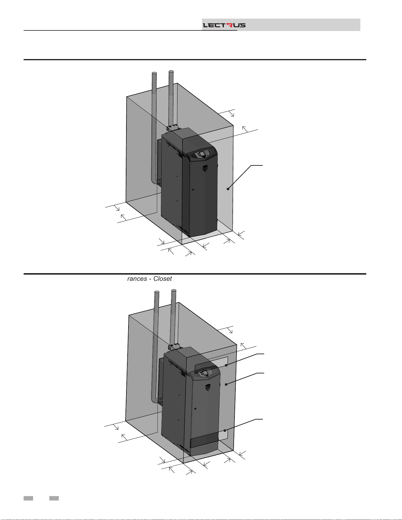
1 Determine boiler location (continued)
Figure 1-2 Minimum Required Clearances - Closet
Figure 1-1 Minimum Required Clearances - Alcove
Installation & Operation Manual
TM
2000665028 01
BACK
36"- 48"
TOP
32"
OPEN DOOR
FRONT
36"- 48"
RIGHT
3"
LEFT
3"
2000665033 01
TOP
32"
FRONT
36"- 48"
RIGHT
3"
LEFT
3"
CLOSED DOOR
VENTILATING AIR
OPENING
VENTILATING AIR
OPENING
BACK
36"- 48"
11
1 Determine boiler location (continued)
MINIMUM service clearances
FRONT - 36" to 48" (92 - 122 cm)*
TOP - 32" (82 cm)
REAR - 36” to 48” (92 - 122 cm)
LEFT - 3" (8 cm)**
RIGHT - 3" (8 cm)**
* - Refer to the NEC section 110.26 and the Table 110.26 (A)
(1) Working Spaces for minimum clear distance based on the
condition applicable to your installation.
** - e minimum clearances on each side of the unit to promote
warm air exhaust for the modulation fan(s) are 3" (8cm). Refer
to the NEC section 110.26 (A)(2) for the minimum width of the
working space in front of the boiler.
Do not install the boiler on carpeting even if
foundation is used. Fire can result, causing
severe personal injury, death, or substantial
property damage.
If ooding is possible, elevate the boiler suciently to prevent
water from reaching the boiler.
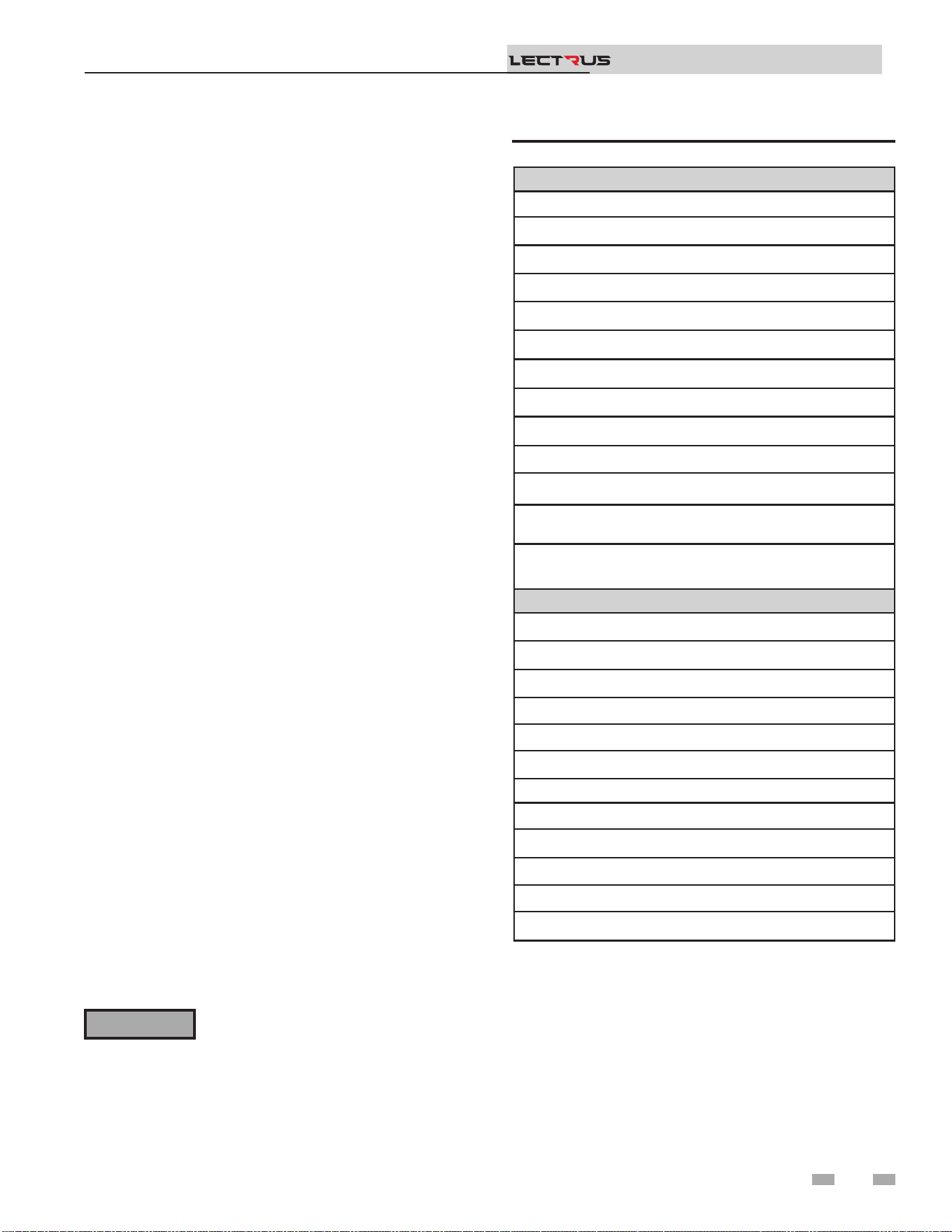
Flooring and foundation
Flooring
e Lectrus is approved for installation on combustible ooring
but must never be installed on carpeting.
⚠WARNING
Installation & Operation Manual
TM
Storage
Electrical equipment can be damaged if exposed to adverse
weather. e boiler should be stored inside. e electrical
panel and controls should be covered with plastic throughout
all construction to avoid accumulation of dust and moisture
on the controls and load components. e contactors can be
damaged by dust / dirt in the mechanism.
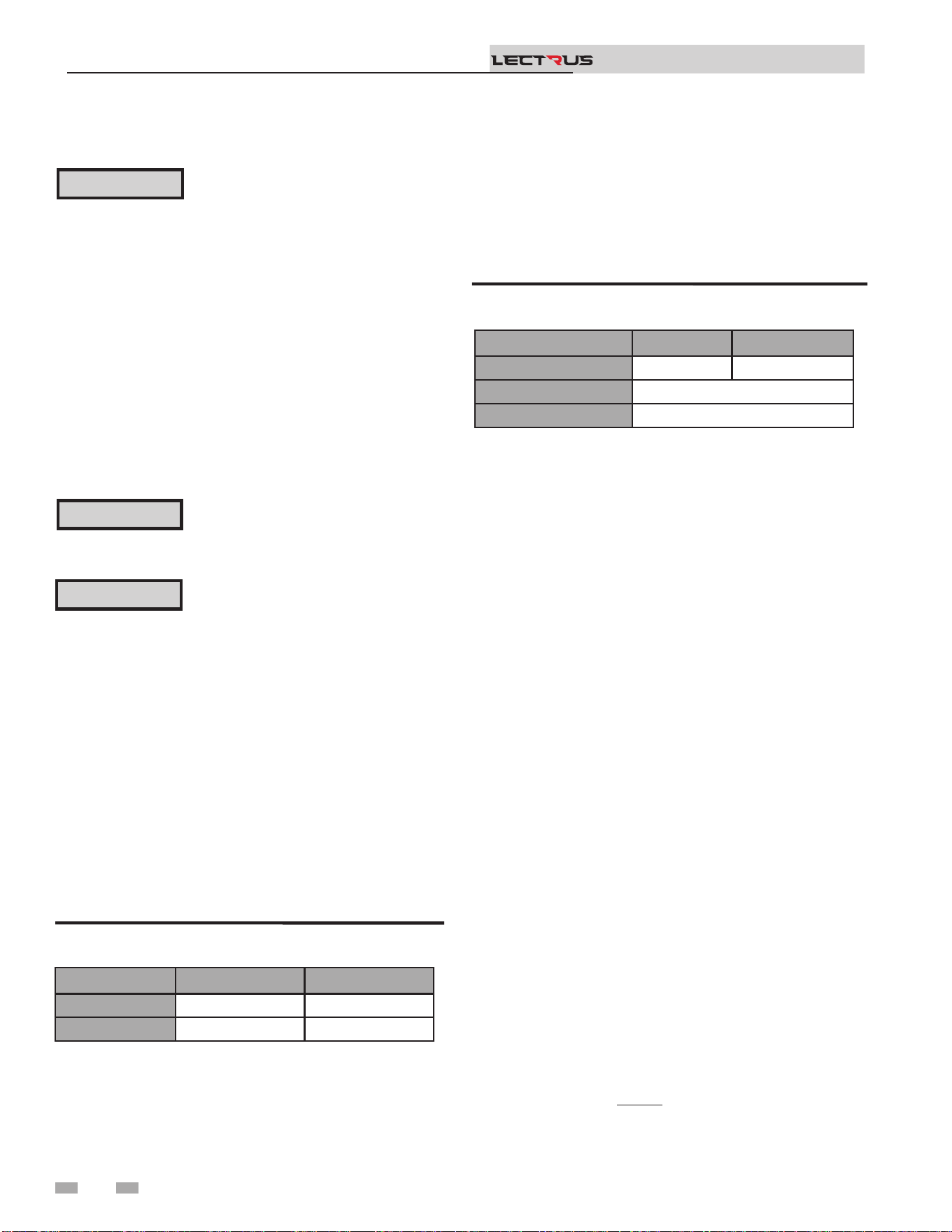
Model Height Width Depth
Water
Connection
Shipping
Weight
Volume
0015 -
0090
47"
16 -
3/4"
41" 2" NPT 367 lbs 17.6 gal
0105 -
0150
47"
21 -
3/4"
45 -
1/2"
2" NPT 488 lbs 32 gal
Table 1A Boiler Dimensions and Specications
Do not install the boiler in an attic.
Failure to comply with the above warning
could result in severe personal injury, death,
or substantial property damage.
⚠WARNING
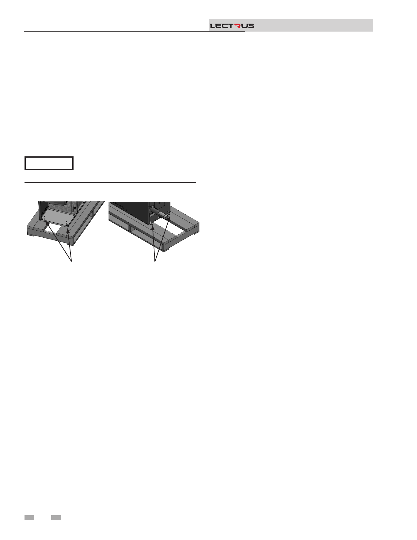
2 Prepare boiler
12
Remove boiler from wood pallet
1. Aer removing the outer shipping carton from the boiler,
remove the parts box.
2. To remove the boiler from the pallet (aer removing the
front door):
a. Remove the two (2) lag bolts from inside the front of
the boiler (FIG. 2-1).
b. Remove the two (2) lag bolts on the rear of the boiler.
c. Before removing the boiler from the pallet or moving
the boiler.
Do not drop the boiler or bump the jacket
on the oor or pallet. Damage to the boiler
can result.
Figure 2-1 Boiler Mounted on Shipping Pallet
NOTICE
Installation & Operation Manual
TM
2000659658 00
LAG BOLTS
(x2)
LAG BOLTS
(x2)
3 Hydronic piping
System water piping methods
e Lectrus is designed to function in a closed loop system
pressurized to not less than 12 psi (83 kPa) (Non-metallic
system piping must have an oxygen barrier to be considered a
closed loop). A temperature and pressure gauges are included
to monitor system pressure and outlet temperature and should
be located on the boiler outlet.
It is important to note that the boiler has a minimal amount
of pressure drop which must be accounted for when sizing the
circulators. Each boiler installation must have an air elimination
device, which will remove air from the system. Install the boiler
so it is protected from water (dripping, spraying, etc.) during
appliance operation or basic service of circulator replacement,
valves, and others.
Observe a minimum of 1/4 inch (6 mm) clearance around all
un-insulated hot water pipes when openings around the pipes
are not protected by non-combustible materials.
Low water cutoff device
is boiler comes equipped with a low water cuto device. On
a boiler installed above radiation level, some states and local
codes require a second low water cuto device at the time of
installation.
Chilled water system
If the boiler supplies hot water to heating coils in air handler
units, ow control valves or other devices must be installed
to prevent gravity circulation of boiler in the coils during the
cooling cycle. A chilled water medium must be piped in parallel
with the boiler.
Freeze protection uids
Freeze protection uids for new or existing systems must
use glycol that is specially formulated for this purpose. is
includes inhibitors, which prevent the glycol from attacking
the metallic system components. Make certain to check that
the system uid is correct for the glycol concentration and
inhibitor level. e system should be tested at least once a year
and as recommended by the producer of the glycol solution.
Allowance should be made for the expansion of the glycol
solution in the system piping.
Use only inhibited propylene glycol
solutions, which are specically formulated
for hydronic systems. Ethylene glycol is
toxic and can attack gaskets and seals used
in hydronic systems.
⚠WARNING
13
Installation & Operation Manual
TM
Products to avoid:
Spray cans containing chloro/uorocarbons
Permanent wave solutions
Chlorinated waxes/cleaners
Chlorine-based swimming pool chemicals
Calcium chloride used for thawing
Sodium chloride used for water soening
Refrigerant leaks
Paint or varnish removers
Hydrochloric acid/muriatic acid
Cements and glues
Antistatic fabric soeners used in clothes dryers
Chlorine-type bleaches, detergents, and cleaning solvents
found in household laundry rooms
Adhesives used to fasten building products and other
similar products
Areas likely to have contaminants
Dry cleaning/laundry areas and establishments
Swimming pools
Metal fabrication plants
Beauty shops
Refrigeration repair shops
Photo processing plants
Auto body shops
Plastic manufacturing plants
Furniture renishing areas and establishments
New building construction
Remodeling areas
Garages with workshops
Table 3A Corrosive Contaminants and Sources
14
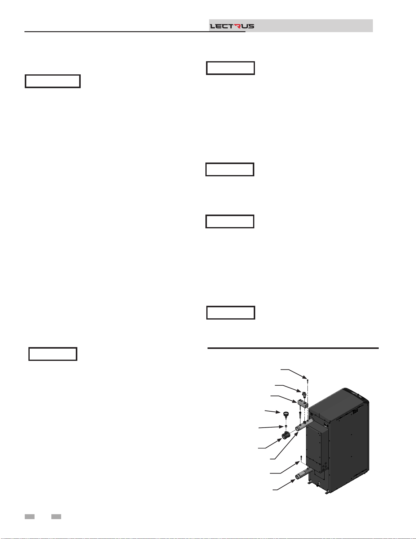
NOTICE
When installing the provided temperature
and pressure gauge (T&P), be sure to use
the tee and bushing provided with the T&P.
Relief valve and temperature and pressure
gauge installation
e boiler has a factory installed relief valve and manual reset
high limit (MRHL). Note that if the MRHL has been factory
installed in a horizontal position, it can be adjusted to a vertical
position.
Figure 3-1 T & P Gauge Installation - Models 0015 -
0150
3 Hydronic piping
See the piping illustrations included in this section, FIG.’s 3-4
and 3-9 for suggested guidelines in piping the Lectrus.
Please note that these illustrations are meant
to show system piping concept only, the
installer is responsible for all equipment and
detailing required by local codes.
NOTICE
A magnetic separator is recommended when
a unit is installed in a retrot system, or
a system containing steel and/or cast-iron
pipe.
NOTICE
e relief valve, tee and any other necessary
ttings are shipped in the install kit with the
boiler and are to be eld installed (FIG. 3-1).
NOTICE
11. Install a eld supplied strainer/lter to prevent damage
to the pressure vessel caused by debris entering from the
system piping. When installing in a pre-existing system, a
strainer/lter capable of removing debris le in the system
is recommended.
12. Install a eld supplied magnetic separator in the heating
system return line as close as practical to the boiler per the
manufacturer’s instructions.
Installation & Operation Manual
TM
Basic steps are listed below along with illustrations on the
following pages (FIG.’s 3-4 through 3-9), which will guide you
through the installation of the Lectrus (reference FIG.’s 3-2A
and 3-2B).
1. Connect the system return marked “Inlet”.
2. Connect the system supply marked “Outlet”.
3. Install purge and balance valve or shuto valve and drain
on system return to purge air out of each zone.
4. Install a backow preventer on the cold feed make-up
water line.
5. Install a pressure reducing valve on the cold feed make-up
water line, (15 psi (103 kPa) nominal). Check temperature
and pressure gauge (shipped separately), which should
read a minimum pressure of 12 psi (83 kPa).
6. Install a circulator as shown on the piping diagrams in this
section. Make sure the circulator is properly sized for the
system and friction loss.
7. Install an expansion tank on the system supply. Consult the
tank manufacturer’s instruction for specic information
relating to tank installation. Size the expansion tank for
the required system volume and capacity.
8. Install an air elimination device on the system supply.
9. Install a drain valve at the lowest point of the system.
Note: e boiler cannot be drained completely of water
without purging the unit with an air pressure of 15 psi
(103 kPa).
IMPORTANT
All boiler piping must contain an oxygen
barrier. is will help prevent any excess
oxygen from entering the system.
General piping information
If the boiler needs to be drained, the power
must be turned OFF. is will prevent
damage to the elements in the boiler.
NOTICE
10. is appliance is supplied with a relief valve sized in
accordance with ASME Boiler and Pressure Vessel Code,
Section IV (“Heating Boilers”). Pipe the discharge of the
safety relief valve to prevent injury in the event of pressure
relief. Pipe the discharge to a drain. Provide piping that is
the same size as the safety relief valve outlet. Never block
the outlet of the safety relief valve.
OUTLET TEMPERATURE
SENSOR
RELIEF VALVE
MANUAL RESET
HIGH LIMIT
TEMPERATURE
GAUGE
BUSHING
TEE
WATER OUTLET
INLET TEMPERATURE
SENSOR
WATER INLET
2000668401 01

3 Hydronic piping (continued)
Near boiler piping components
1. Boiler system piping:
Boiler system piping MUST be sized per the pipe
requirements listed in Table 3C. Reducing the pipe size
can restrict the ow rate through the boiler, causing
inadvertent high limit shutdowns and poor system
performance. Flow rates are based on a full ow
application.
2. Boiler system circulating pump:
Field supplied. e boiler circulating pump should be
based on system requirements.
3. Domestic hot water circulating pump:
Field supplied. e pump MUST be sized to meet
the specied minimum ow requirements listed in
FIG. 3-3. Consult the indirect water heater operating
guide to determine ow characteristics for the selected
product used.
4. Variable speed boiler circulator:
Lectrus boilers are capable of controlling a variable speed
boiler circulator. Variable speed circulators MUST
be sized to meet the specied minimum ow requirements
listed in FIG. 3-3 on page 17 at full speed. To be used
in primary/secondary systems only.
5. Boiler isolation valves:
Field supplied. Full port ball valves are required. Failure
to use full port ball valves could result in a restricted ow
rate through the boiler.
6. Check valves:
Field supplied. Check valves are recommended for
installation as shown in FIG.’s 3-4 through 3-9. Failure
to install check valves could result in a reverse ow
condition during pump(s) o cycle.
7. Domestic indirect hot water isolation valves:
Field supplied. Full port ball valves are required. Failure
to use full port ball valves could result in a restricted ow
rate through the boiler.
8. Anti-scald mixing valve:
Field supplied. An anti-scald mixing valve is
recommended when storing domestic hot water above
115°F (46°C).
9. Unions:
Field supplied. Recommended for unit serviceability.
10. Temperature and pressure gauge:
Factory supplied. e temperature and pressure gauge is
shipped loose. It is the responsibility of the contractor to
install the temperature and pressure gauge on the boiler
water outlet.
11. Pressure relief valve:
Factory supplied. e pressure relief valve is sized to
ASME specications.
15
Circulator sizing
e Lectrus pressure vessel does have a pressure drop, which
must be considered in your system design. Refer to the graphs
in FIG. 3-3 for pressure drop through the Lectrus pressure
vessel.
12. Boiler purge valve:
Field supplied. e boiler purge valve is used to
remove entrapped air from the pressure vessel during
start-up.
13. System temperature sensor:
Lochinvar supplies a system temperature sensor. e
sensor is to be installed in the heating loop downstream
from the boiler hot water piping and heating loop
junction. e sensor should be located far enough
downstream to sense system diluted water temperature.
14. Water Meter:
Field supplied. A water meter to monitor makeup water is
recommended. Makeup water volume should not exceed
5% of total system per year.
15. Strainer/Filter:
Field supplied. Install a Y-strainer or equivalent multi-
purpose strainer/lter just before the boiler pump at
the inlet of the pressure vessel. is item is used to
remove system debris from older hydronic systems and
to protect newer systems.
16. Motorized isolation valve (optional):
Field supplied. A motorized isolation valve can be used
to isolate the boiler from the system piping.
17. Magnetic Separator:
Field supplied. Install a magnetic separator in the
heating system return line as close as practical to the
boiler per the manufacturer’s instructions.
Installation & Operation Manual
TM
16
3 Hydronic piping
Installation & Operation Manual
TM
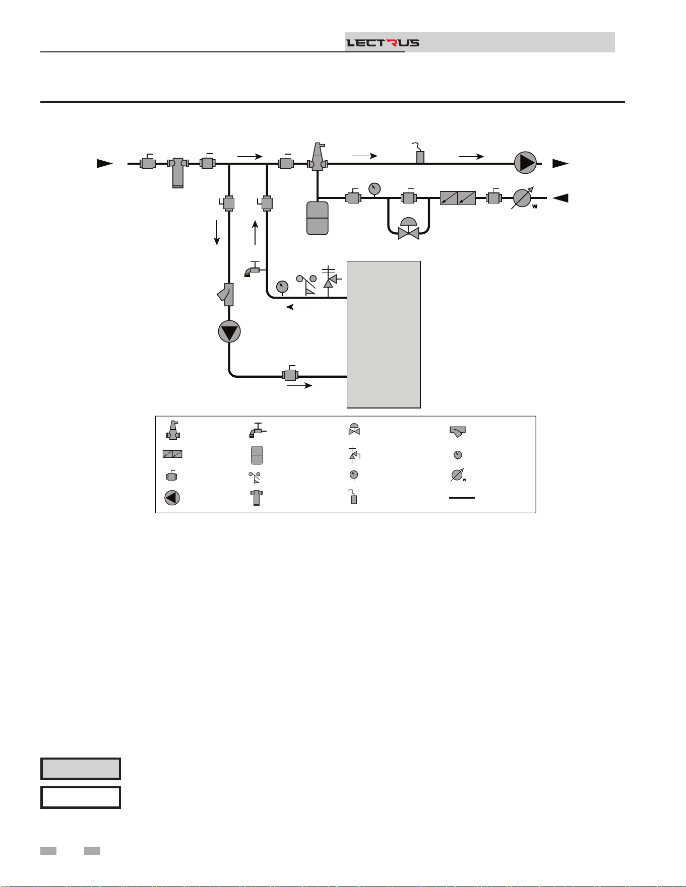
Figure 3-2A Near Boiler Piping w/Y-Strainer
Please note that these illustrations are meant to show system piping concept only, the installer is responsible for
all equipment and detailing required by local codes. Connection locations shown are for reference only and will
vary with boiler type.
NOTICE
CAUTION
Mixing valves are required for the protection of low temperature loops.
2000809707 00
TO
SYSTEM
FROM
SYSTEM
MAKE UP
WATER
BOILER
P
T P
LEGEND
AIR SEPARATOR
CIRCULATION
PUMP
FLOW SWITCH
OPTIONAL
PRESSURE GAUGE
P
TEMPERATURE &
PRESSURE GAUGE
T P
SYSTEM SUPPLY
SENSOR
BACKFLOW
PREVENTER
MAGNETIC SEPARATOR
WATER METER
STRAINER / FILTER
PRESSURE
REDUCING VALVE
PRESSURE RELIEF
VALVE
BALL VALVE
EXPANSION TANK
PIPING
DRAIN PORT
3 Hydronic piping (continued)
17
Installation & Operation Manual
TM
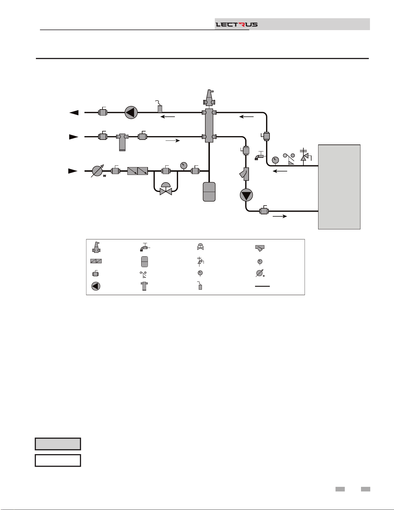
Figure 3-2B Near Boiler Piping w/Low Loss Header
Please note that these illustrations are meant to show system piping concept only, the installer is responsible for
all equipment and detailing required by local codes. Connection locations shown are for reference only and will
vary with boiler type.
NOTICE
CAUTION
Mixing valves are required for the protection of low temperature loops.
2000809731 00
TO
SYSTEM
FROM
SYSTEM
BOILER
MAKE UP
WATER
P
T P
LOW LOSS
HEADER
LEGEND
AIR SEPARATOR
CIRCULATION
PUMP
FLOW SWITCH
OPTIONAL
PRESSURE GAUGE
P
TEMPERATURE &
PRESSURE GAUGE
T P
SYSTEM SUPPLY
SENSOR
BACKFLOW
PREVENTER
MAGNETIC SEPARATOR
WATER METER
STRAINER / FILTER
PRESSURE
REDUCING VALVE
PRESSURE RELIEF
VALVE
BALL VALVE
EXPANSION TANK
PIPING
DRAIN PORT
18
3 Hydronic piping
Installation & Operation Manual
TM
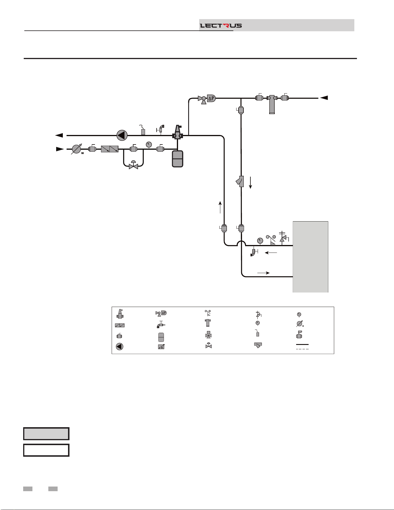
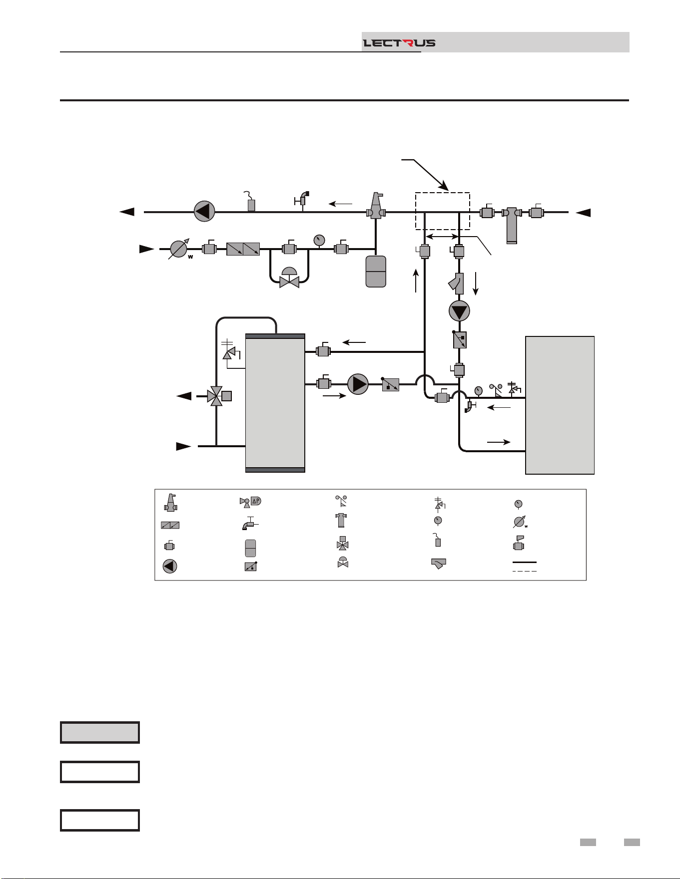
Figure 3-2C Single Boiler - Alternate - Fixed or Variable Flow Primary System Piping
Please note that these illustrations are meant to show system piping concept only, the installer is responsible for
all equipment and detailing required by local codes. Connection locations shown are for reference only and will
vary with boiler type.
NOTICE
CAUTION
Mixing valves are required for the protection of low temperature loops.
2000598465
MAKE UP
WATER
P
TO
SYSTEM
FROM
SYSTEM
LEGEND
AIR SEPARATOR
CIRCULATION
PUMP
FLOW CHECK VALVE
PRESSURE GAUGE
P
TEMPERATURE &
PRESSURE GAUGE
T P
SYSTEM SUPPLY
SENSOR
BACKFLOW
PREVENTER
MAGNETIC SEPARATOR
WATER METER
STRAINER / FILTER
PRESSURE
REDUCING VALVE
PRESSURE RELIEF
VALVE
BALL VALVE
EXPANSION TANK
PIPING
DRAIN PORT
DIFFERENTIAL
PRESSURE
BYPASS VALVE
2 WAY MOTORIZED
VALVE
MIXING VALVE
ANTI SCALD
FLOW SWITCH
OPTIONAL
WIRING
BOILER
T P
19
3 Hydronic piping
Variable speed pump option
Variable speed pump setup
Before operation, ensure the following:
- Pump is set for an input signal of 0 - 10VDC by the
dip switches on the pump control
- Pump is set for external signal control (if applicable)
- Pump is set for linear output (if applicable)
- If pump does not come equipped with a 0 - 10 VDC
input option, an optional module will be required
from the vendor
SMART SYSTEM
e Lectrus boiler has one heat demand and produces one
set point temperature. ird party zone device managers
will be required if installing in a system that require multiple
zone temperatures. When using more than one temperature
demand it is necessary to protect the lower temperature loop(s)
from overheating.
Near boiler piping connections
⚠ CAUTION
e maximum allowable water ow rate
through a single Lectrus boiler is 105 GPM.
Exceeding this ow rate will result in
damage to the pressure vessel and/or piping.
NOTICE
Reference Table 3C for the minimum
recommended ow rate through a single
Lectrus boiler at full power to maintain a
80°F temperature rise. Reference Table
3B for the absolute minimum ow rate
through a single Lectrus boiler.
Installation & Operation Manual
TM
ABSOLUTE MINIMUM FLOW RATE
MODEL FLOW RATE (GPM)
15 KW to 75 KW 1.3
90 KW to 150 KW 2.6
[Based on 80°F Temperature Rise]
Table 3B Absolute Minimum Flow Rate at Low Power
20
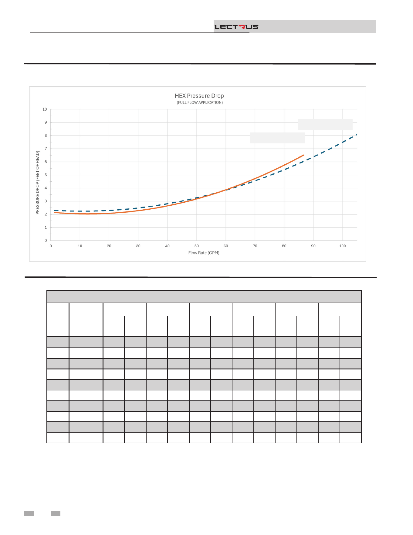
Figure 3-3 Pressure Drop vs. Flow Through the Heat Exchanger
Table 3C Sizing Information for Temperature Rise Applications_10°F, 20°F, 30°F, and 40°F
TEMPERATURE RISE APPLICATIONS
Model
MINIMUM
PIPE
SIZE
10°F 20°F 30°F 40°F
60°F 80°F
GPM FT/HD GPM FT/HD GPM FT/HD GPM FT/HD GPM FT/HD GPM FT/HD
015 2" 10.20 1.73 5.10 1.73 3.50 1.94 2.60 2.08 1.70 2.40 1.30 2.54
030 2" 20.70 2.12 10.20 1.92 6.90 1.92 5.20 1.96 3.40 1.98 2.60 2.10
045 2" 30.80 2.31 15.60 2.03 10.60 1.85 7.80 2.05 5.20 2.01 3.80 2.24
060 2" 40.90 2.75 20.70 2.03 13.70 2.03 10.60 2.03 6.80 2.10 5.20 2.31
075 2" 51.50 3.32 25.80 2.19 17.50 2.10 13.19 1.94 8.60 2.17 6.40 2.12
090 2" 61.60 3.90 30.73 2.40 20.50 2.21 15.78 2.12 10.35 2.01 7.89 2.19
105 2" 72.60 4.82 36.33 2.58 24.28 2.31 18.80 2.35 12.07 2.63 9.27 2.63
120 2" 82.53 5.63 41.30 2.84 27.87 2.38 21.00 2.38 14.30 2.42 10.73 2.68
135 2" 92.30 6.81 46.62 3.14 30.93 2.56 24.08 2.47 15.81 2.45 11.84 2.65
150 2" 103.10 7.68 55.04 3.76 34.71 2.77 25.84 2.65 17.78 2.54 13.03 2.63
3 Hydronic piping (continued)
Installation & Operation Manual
TM
KEB0015-KEB0090
KEB0105-KEB0150
21
3 Hydronic piping
Figure 3-4 Multiple Boilers - Alternate - Fixed or Variable Flow Primary System Piping
Please note that these illustrations are meant to show system piping concept only, the installer is responsible for
all equipment and detailing required by local codes. Connection locations shown are for reference only and will
vary with boiler type.
NOTICE
CAUTION
Mixing valves are required for the protection of low temperature loops.
Installation & Operation Manual
TM
Model
Number of Units
2 3 4 5 6 7 8
Manifold Pipe Sizes in Inches (mm)
0015
to
0150
3 1/2 (89) 4 (102) 5 (127) 6 (152) 6 (152) 8 (203) 8 (203)
2000809751 01
BOILER 1
T P
MAKE UP
WATER
P
TO
SYSTEM
FROM
SYSTEM
LEGEND
AIR SEPARATOR
CIRCULATION
PUMP
FLOW CHECK VALVE
PRESSURE GAUGE
P
TEMPERATURE &
PRESSURE GAUGE
T P
SYSTEM SUPPLY
SENSOR
BACKFLOW
PREVENTER
MAGNETIC SEPARATOR
WATER METER
STRAINER / FILTER
PRESSURE
REDUCING VALVE
PRESSURE RELIEF
VALVE
BALL VALVE
EXPANSION TANK
PIPING
DRAIN PORT
DIFFERENTIAL
PRESSURE
BYPASS VALVE
2 WAY MOTORIZED
VALVE (OPTIONAL)
MIXING VALVE
ANTI SCALD
FLOW SWITCH
OPTIONAL
WIRING
BOILER 2
T P
3 Hydronic piping (continued)
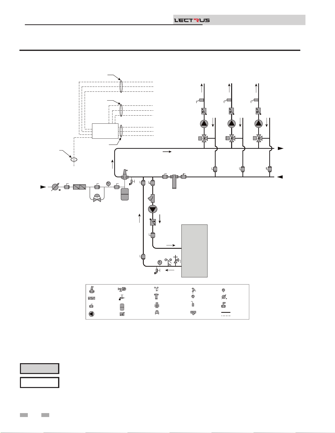
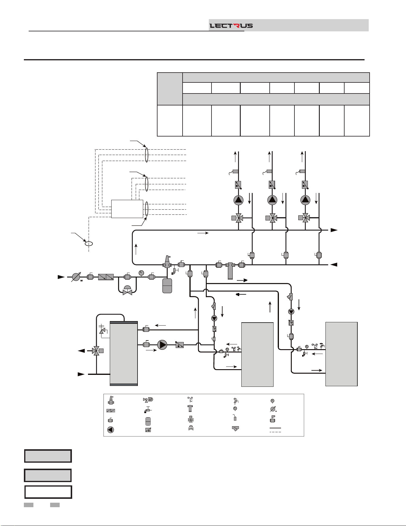
Figure 3-5 Single Boiler - Multiple Temperatures
Please note that these illustrations are meant to show system piping concept only, the installer is responsible for
all equipment and detailing required by local codes. Connection locations shown are for reference only and will
vary with boiler type.
NOTICE
CAUTION
Mixing valves are required for the protection of low temperature loops.
Installation & Operation Manual
TM
2000809762 01
BOILER
T P
MAKE UP
WATER
P
TO
SYSTEM
FIELD INSTALLED
ZONE / LOOP
CONTROLLER
(OPTIONAL)
FROM
SYSTEM
TEMP
LOOP 3
TEMP
LOOP 2
TEMP
LOOP 1
24VAC SIGNAL TO
MIXING VALVES
BOILER
ENABLE
SIGNAL
120VAC
TO PUMPS
WIRES TO
LOOP SENSORS
SENSOR 1
PUMP 1
VALVE 1
SENSOR 3
SENSOR 2
PUMP 3
PUMP 2
VALVE 3
VALVE 2
SENSOR 1 SENSOR 2 SENSOR 3
PUMP 1 PUMP 2
PUMP 3
VALVE 1 VALVE 2 VALVE 3
LEGEND
AIR SEPARATOR
CIRCULATION
PUMP
FLOW CHECK VALVE
PRESSURE GAUGE
P
TEMPERATURE &
PRESSURE GAUGE
T P
SYSTEM SUPPLY
SENSOR
BACKFLOW
PREVENTER
MAGNETIC SEPARATOR
WATER METER
STRAINER / FILTER
PRESSURE
REDUCING VALVE
PRESSURE RELIEF
VALVE
BALL VALVE
EXPANSION TANK
PIPING
DRAIN PORT
DIFFERENTIAL
PRESSURE
BYPASS VALVE
2 WAY MOTORIZED
VALVE (OPTIONAL)
MIXING VALVE
ANTI SCALD
FLOW SWITCH
OPTIONAL
WIRING
22
3 Hydronic piping
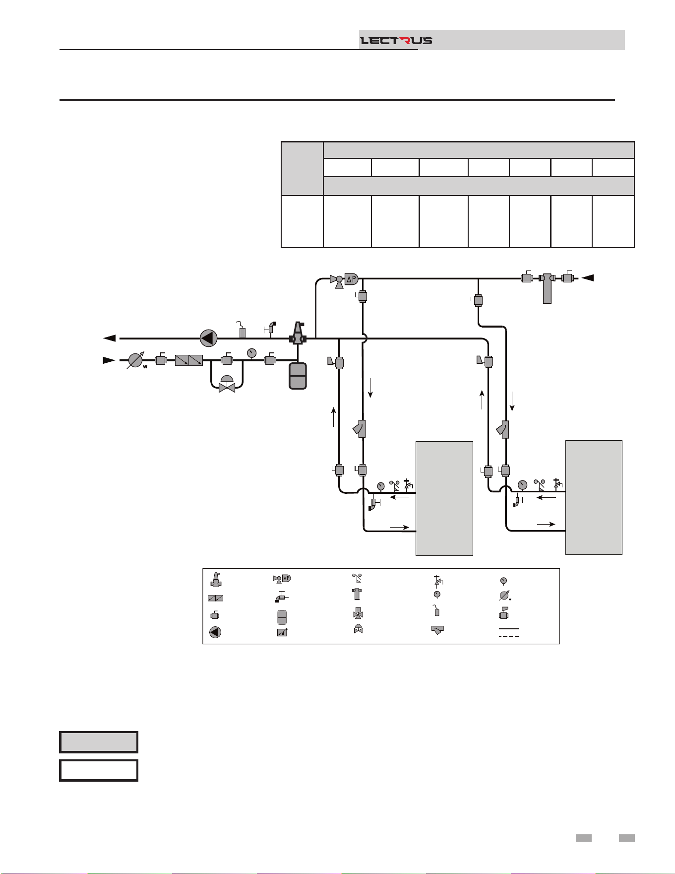
Figure 3-6 Single Boiler - Primary/Secondary Piping
NOTICE
System ow should always remain higher than the required ow for the boiler(s) when the boiler(s) is in
operation to prevent short cycling and high limit issues.
Please note that these illustrations are meant to show system piping concept only, the installer is responsible
for all equipment and detailing required by local codes. Connection locations shown are for reference only and
will vary with boiler type.
NOTICE
CAUTION
Indirect water heaters are capable of transferring a limited number of Btu’s into the water. Ensure boiler output
does not exceed indirect boiler transfer capabilities.
Installation & Operation Manual
TM
2000809763 00
INDIRECT
DHW
TANK
BOILER
T P
MAKE UP
WATER
P
TO
SYSTEM
FROM
SYSTEM
MAY SUBTITUTE
LOW LOSS HEADER
NOT TO EXCEED 4 PIPE DIA OR
MAX OF 12” APART
COLD
WATER IN
DWH HOT
WATER OUT
LEGEND
AIR SEPARATOR
CIRCULATION
PUMP
FLOW CHECK VALVE
PRESSURE GAUGE
P
TEMPERATURE &
PRESSURE GAUGE
T P
SYSTEM SUPPLY
SENSOR
BACKFLOW
PREVENTER
MAGNETIC SEPARATOR
WATER METER
STRAINER / FILTER
PRESSURE
REDUCING VALVE
PRESSURE RELIEF
VALVE
BALL VALVE
EXPANSION TANK
PIPING
DRAIN PORT
DIFFERENTIAL
PRESSURE
BYPASS VALVE
2 WAY MOTORIZED
VALVE (OPTIONAL)
MIXING VALVE
ANTI SCALD
FLOW SWITCH
OPTIONAL
WIRING
23
3 Hydronic piping (continued)
Figure 3-7 Multiple Boilers - Multiple Temperatures
Please note that these illustrations are meant to show system piping concept only, the installer is responsible
for all equipment and detailing required by local codes. Connection locations shown are for reference only and
will vary with boiler type.
NOTICE
CAUTION
Mixing valves are required for the protection of low temperature loops.
CAUTION
Indirect water heaters are capable of transferring a limited number of Btu’s into the water. Ensure boiler output
does not exceed indirect boiler transfer capabilities.
Installation & Operation Manual
TM
Model
Number of Units
2 3 4 5 6 7 8
Manifold Pipe Sizes in Inches (mm)
0015
to
0150
3 1/2 (89) 4 (102) 5 (127) 6 (152) 6 (152) 8 (203) 8 (203)
2000809764 00
INDIRECT
DHW
TANK
BOILER 1
MAKE UP
WATER
P
TO
SYSTEM
FIELD INSTALLED
ZONE / LOOP
CONTROLLER
(OPTIONAL)
FROM
SYSTEM
TEMP
LOOP 3
TEMP
LOOP 2
TEMP
LOOP 1
24VAC SIGNAL TO
MIXING VALVES
BOILER
ENABLE
SIGNAL
120VAC
TO PUMPS
WIRES TO
LOOP SENSORS
SENSOR 1
PUMP 1
VALVE 1
SENSOR 3
SENSOR 2
PUMP 3
PUMP 2
VALVE 3
VALVE 2
SENSOR 1 SENSOR 2 SENSOR 3
PUMP 1 PUMP 2
PUMP 3
VALVE 1 VALVE 2 VALVE 3
LEGEND
AIR SEPARATOR
CIRCULATION
PUMP
FLOW CHECK VALVE
PRESSURE GAUGE
P
TEMPERATURE &
PRESSURE GAUGE
T P
SYSTEM SUPPLY
SENSOR
BACKFLOW
PREVENTER
MAGNETIC SEPARATOR
WATER METER
STRAINER / FILTER
PRESSURE
REDUCING VALVE
PRESSURE RELIEF
VALVE
BALL VALVE
EXPANSION TANK
PIPING
DRAIN PORT
DIFFERENTIAL
PRESSURE
BYPASS VALVE
2 WAY MOTORIZED
VALVE (OPTIONAL)
MIXING VALVE
ANTI SCALD
FLOW SWITCH
OPTIONAL
WIRING
BOILER 2
COLD
WATER IN
DWH HOT
WATER OUT
T P
T P
24
3 Hydronic piping
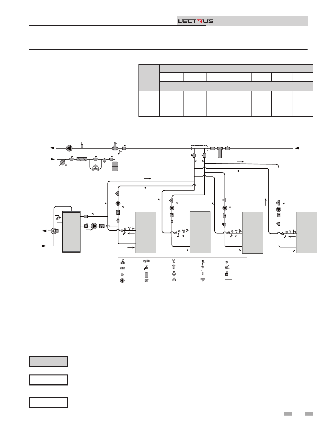
Figure 3-8 Multiple Boilers - Primary/Secondary Piping
NOTICE
System ow should always remain higher than the required ow for the boiler(s) when the boiler(s) is in
operation to prevent short cycling and high limit issues.
Please note that these illustrations are meant to show system piping concept only, the installer is responsible
for all equipment and detailing required by local codes. Connection locations shown are for reference only and
will vary with boiler type.
NOTICE
CAUTION
Indirect water heaters are capable of transferring a limited number of Btu’s into the water. Ensure boiler output
does not exceed indirect boiler transfer capabilities.
Installation & Operation Manual
TM
Model
Number of Units
2 3 4 5 6 7 8
Manifold Pipe Sizes in Inches (mm)
0015
to
0150
3 1/2 (89) 4 (102) 5 (127) 6 (152) 6 (152) 8 (203) 8 (203)
2000809765 00
INDIRECT
DHW
TANK
BOILER 1
MAKE UP
WATER
P
TO
SYSTEM
FROM
SYSTEM
LEGEND
AIR SEPARATOR
CIRCULATION
PUMP
FLOW CHECK VALVE
PRESSURE GAUGE
P
TEMPERATURE &
PRESSURE GAUGE
T P
SYSTEM SUPPLY
SENSOR
BACKFLOW
PREVENTER
MAGNETIC SEPARATOR
WATER METER
STRAINER / FILTER
PRESSURE
REDUCING VALVE
PRESSURE RELIEF
VALVE
BALL VALVE
EXPANSION TANK
PIPING
DRAIN PORT
DIFFERENTIAL
PRESSURE
BYPASS VALVE
2 WAY MOTORIZED
VALVE (OPTIONAL)
MIXING VALVE
ANTI SCALD
FLOW SWITCH
OPTIONAL
WIRING
BOILER 2
BOILER 3 BOILER 4
MAY SUBTITUTE
LOW LOSS HEADER
NOT TO EXCEED 4 PIPE DIA OR
MAX OF 12” APART
COLD
WATER IN
DWH HOT
WATER OUT
T P
T P
T P
T P
25
3 Hydronic piping (continued)
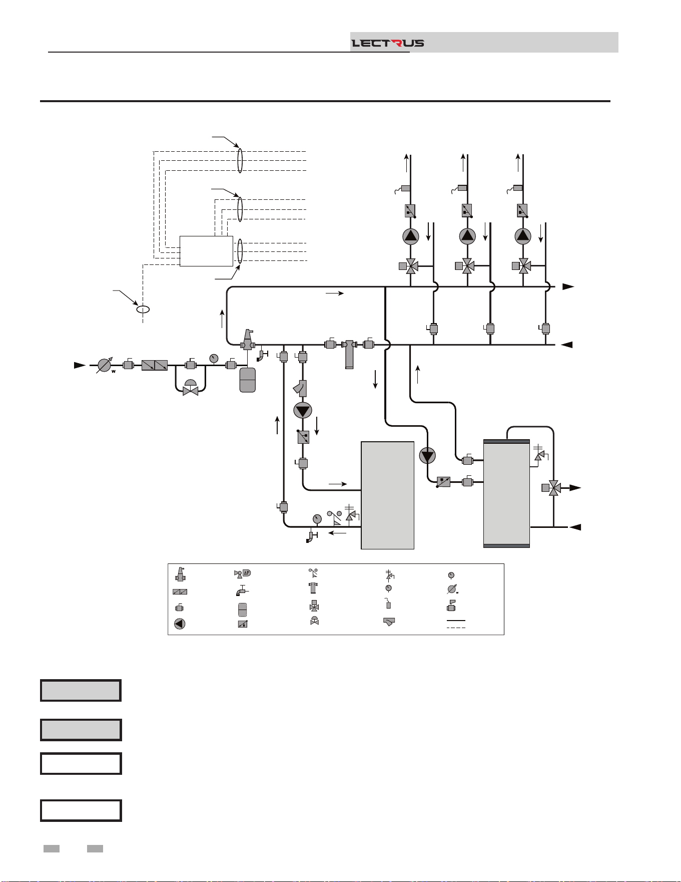
Figure 3-9 Single Boiler - Multiple Temperatures with DHW Piped as a Zone
Please note that these illustrations are meant to show system piping concept only, the installer is responsible
for all equipment and detailing required by local codes. Connection locations shown are for reference only and
will vary with boiler type.
NOTICE
Please note that the installer is responsible for ensuring DHW prioritization when piped as a zone.
NOTICE
CAUTION
Mixing valves are required for the protection of low temperature loops.
CAUTION
Indirect water heaters are capable of transferring a limited number of Btu’s into the water. Ensure boiler output
does not exceed indirect boiler transfer capabilities.
Installation & Operation Manual
TM
2000809766 01
INDIRECT
DHW
TANK
MAKE UP
WATER
P
TO
SYSTEM
FROM
SYSTEM
TEMP
LOOP 3
TEMP
LOOP 2
TEMP
LOOP 1
24VAC SIGNAL TO
MIXING VALVES
BOILER
ENABLE
SIGNAL
120VAC
TO PUMPS
WIRES TO
LOOP SENSORS
SENSOR 1
PUMP 1
VALVE 1
SENSOR 3
SENSOR 2
PUMP 3
PUMP 2
VALVE 3
VALVE 2
SENSOR 1 SENSOR 2 SENSOR 3
PUMP 1 PUMP 2
PUMP 3
VALVE 1 VALVE 2 VALVE 3
LEGEND
AIR SEPARATOR
CIRCULATION
PUMP
FLOW CHECK VALVE
PRESSURE GAUGE
P
TEMPERATURE &
PRESSURE GAUGE
T P
SYSTEM SUPPLY
SENSOR
BACKFLOW
PREVENTER
MAGNETIC SEPARATOR
WATER METER
STRAINER / FILTER
PRESSURE
REDUCING VALVE
PRESSURE RELIEF
VALVE
BALL VALVE
EXPANSION TANK
PIPING
DRAIN PORT
DIFFERENTIAL
PRESSURE
BYPASS VALVE
2 WAY MOTORIZED
VALVE (OPTIONAL)
MIXING VALVE
ANTI SCALD
FLOW SWITCH
OPTIONAL
WIRING
COLD
WATER IN
DWH HOT
WATER OUT
BOILER
T P
FIELD INSTALLED
ZONE / LOOP
CONTROLLER
(OPTIONAL)
26
4 Field wiring
ELECTRICAL SHOCK HAZARD – For
your safety, turn o electrical power supply
before making any electrical connections
to avoid possible electric shock hazard.
Failure to do so can cause severe personal
injury or death.
Wiring must be N.E.C. Class 1.
If original wiring as supplied with boiler
must be replaced, use only type 105°C
wire or equivalent.
Boiler must be electrically grounded as
required by National Electrical Code
ANSI/NFPA 70 – latest edition.
Installation must comply with:
1. National Electrical Code and any other national, state,
provincial, or local codes, or regulations.
2. In Canada, CSA C22.1 Canadian Electrical Code Part 1, and
any local codes.
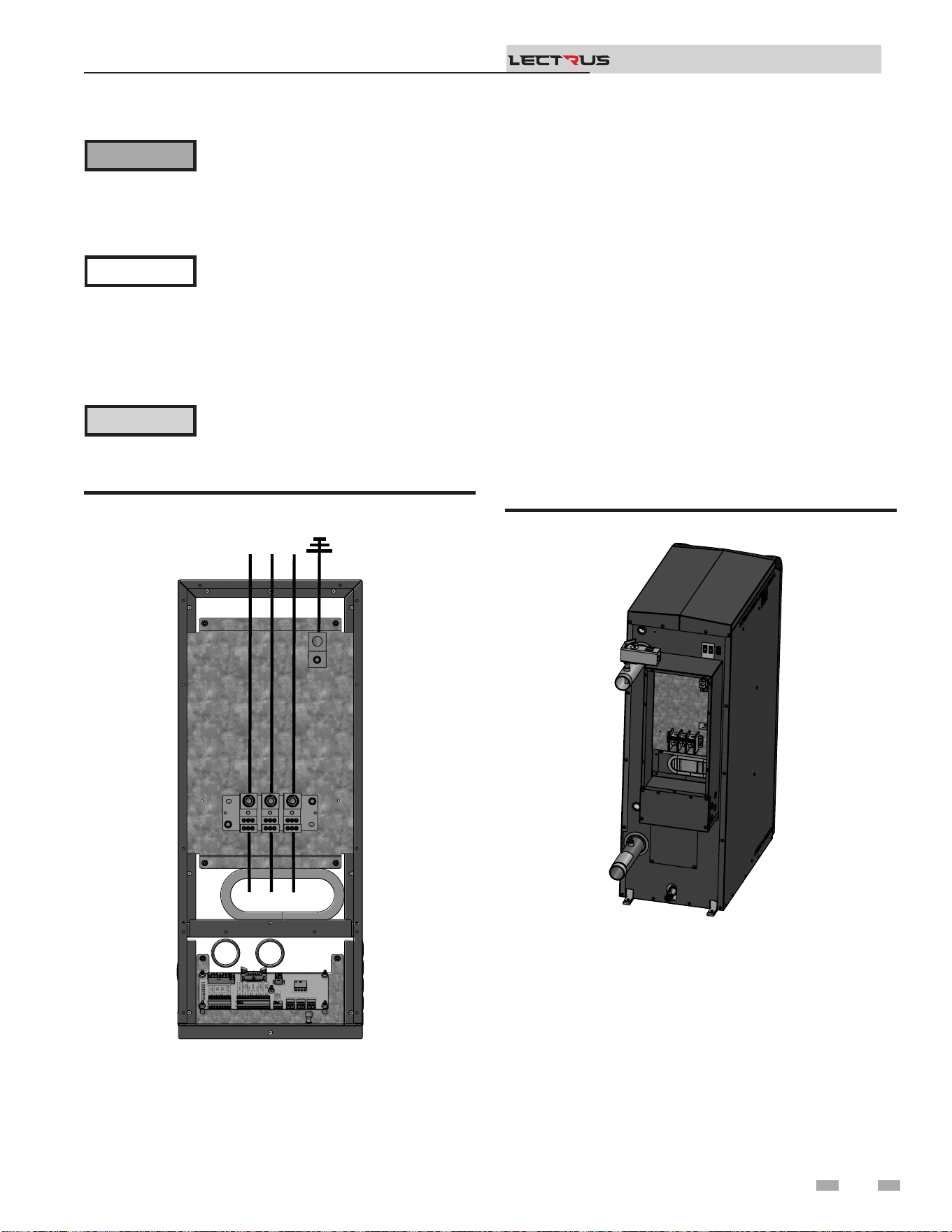
Line voltage connections
1. Connect the power wiring to the line voltage distribution
block in the back of the unit.
2. Provide and install a fused disconnect or service switch as
required by the code (see Table 4C).
3. When connecting a domestic hot water (DHW) pump,
connect the wiring to a 120 VAC power wiring as shown in
FIG. 4-3.
4. To activate a boiler or system pump, wire as shown in FIG.
4-3. Dry contacts are sized for 1.5 hp/120V, 3 hp/240V or
30 amps.
Figure 4-1 Line Voltage Field Wiring Connections
Label all wires prior to disconnection
when servicing controls. Wiring errors
can cause improper and dangerous
operation.
⚠WARNING
NOTICE
⚠ CAUTION
Low voltage connections
1. Route all low voltage wires through the knockouts in the
rear of the boiler, as shown in FIG. 4-2.
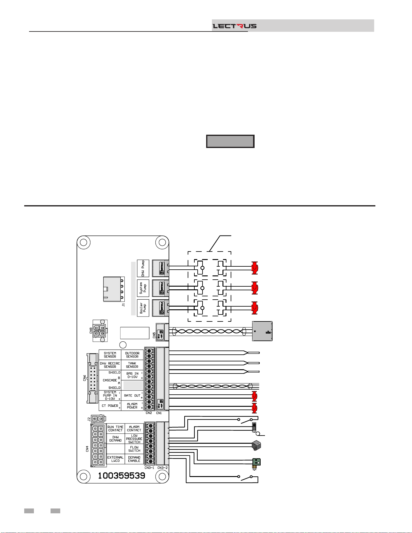
2. Connect low voltage wiring to the low voltage connection
board as shown in FIG. 4-3 on page 27 of this manual and
the boiler wiring diagram.
Figure 4-2 Routing Field Wiring
Thermostat
1. Connect the room thermostats or end switches (isolated
contact only) to heat/loop demand as shown in FIG. 4-3.
2. Install the thermostat on the inside wall away from
inuences of dras, hot or cold-water pipes, lighting
xtures, television, sunlight, or replaces.
3. ermostat anticipator (if applicable):
a. If connected directly to boiler, set for 0.1 amps.
b. If connected to relays or other devices, set to match
total electrical power requirements of connected
devices. See device manufacturers’ specications
and thermostat instructions for details.
Installation & Operation Manual
TM
2000668409 01
2000668850 01
L-1
L-2
L-3
UNIT WIRING
27

4 Field wiring (continued)
Outdoor temperature sensor
1. Mount the sensor on an exterior wall, shielded from direct
sunlight or ow of heat or cooling from other sources.
2. Route sensor wires through a knockout at the rear of the
boiler (see FIG. 4-2).
3. Connect the outdoor temperature sensor (FIG. 4-3) to
the outdoor sensor terminals on the connection board
to enable outdoor reset operation of the Lectrus. If xed
temperature operation is required, do not install outdoor
sensor.
DHW (Domestic Hot Water)
thermostat
Connect the indirect water heater (DHW) thermostat (FIG.
4-3) to the DHW thermostat terminals on the connection
board. If a tank sensor is connected (see DHW Tank Sensor
below) the tank thermostat is ignored.
DHW tank sensor
By installing a tank sensor, the SMART SYSTEM control can
perform the tank thermostat function. e SMART SYSTEM
control automatically detects the presence of this sensor and
generates a DHW call for heat when the tank temperature drops
6°F (3°C) below the tank set point and nishes the call for heat
when the tank temperature reaches the tank set point.
e tank sensor included with the Lochinvar Squire® indirect
DHW tanks (100170544) is the only sensor suitable for use with
the SMART SYSTEM control. Connect the sensor leads to the
Tank Sensor terminals on the low voltage connection board
(FIG. 4-3).
Failure to use the correct sensor may result
in the tank temperature being either above
or below the set point.
⚠WARNING
If 100170544 is not compatible with the indirect tank, a tank
thermostat can be used to control the boiler. e tank thermostat
should be installed per the manufacturer’s instructions and
wired to the DHW ermostat terminals on the low voltage
connection board (FIG. 4-3).
Variable speed system pump
If a variable speed pump is used in the primary loop, and
a 0-10V signal is available from the pump speed control,
this signal can be used by the SMART SYSTEM control to
anticipate changes in the building heat load. By connecting
this 0 - 10V signal to the 0 - 10V SYS PUMP IN terminals, the
boiler (or cascade) can modulate up and down as the primary
ow increases and decreases.
Installation & Operation Manual
TM
Boiler pump speed output
is 0 - 10V output is available to control the speed of a
variable speed boiler pump. e SMART SYSTEM control will
vary the speed of this pump to maintain a minimum DT across
the pressure vessel, as well as prevent high limit lockouts when
the ow in the primary loop is extremely low. NOTE: is
feature is to be used with Primary / Secondary piping systems
only. A system supply sensor MUST be installed. Connect this
output to the 0 - 10V input on the boiler pump speed control.
Rate output
is output provides a 0 - 10V signal that is proportional to the
element power of the boiler. is may be used by a BMS system
to monitor the actual rate of the boiler.
ModBus/BACnet
When an optional ModBus or BACnet interface module is
installed, the RS-485 cable is connected to these terminals. Use
shielded, 2-wire twisted pair cable. If desired, the shield can
be connected to ground by installing a jumper wire between
terminals 1 and 3 on connector X5 on the optional ModBus or
BACnet interface module.
Flow switch (optional)
1. A ow switch is used to guarantee ow through the boiler
before allowing it to cycle. e ow switch must be
installed at the boiler outlet.
2. Remove the jumper wire from the terminals on the
connection board and connect these terminals to the
normally open contacts on the ow switch (FIG. 4-3).
System supply sensor
1. By installing the system supply sensor into the supply of
the primary loop, the temperature of the system supply can
be controlled. e SMART SYSTEM control automatically
detects the presence of this sensor and controls the boiler
element power to maintain the system supply temperature
to the set point (if outlet sensor control is currently
selected).
See the Lectrus Service Manual for instructions on how to
use the inlet sensor as the controlling sensor. When the
inlet sensor is programmed as the controlling sensor, it is
vital that the SYSTEM SUPPLY sensor be installed. DO
NOT INSTALL THE SYSTEM SUPPLY SENSOR INTO
THE SYSTEM RETURN.
2. e 100170581 sensor provided with the boiler must be
used for the system sensor.
3. Connect these terminals to the system supply sensor
(FIG. 4-3).
28

4 Field wiring
Connect the system supply sensor and outdoor air sensor (if
used) to the Leader boiler. For the Cascade system to work
properly the system supply sensor must be installed. e
location of the system supply sensor should be downstream
of the boiler connections in the main system loop (FIG.’s
3-4 through 3-9). e system supply sensor should be wired
to the Connection Board at the terminals marked for the
system sensor (see FIG. 4-3). e Leader control will use the
water temperature at the system supply sensor to control the
operation of the Cascade.
If outdoor air reset is desired, the outdoor air sensor should
be wired to the Connection Board at the terminals marked
for the outdoor sensor (FIG. 4-3). If the outdoor air sensor
is connected, the Leader control will calculate the water
temperature set point based on the programmed reset curve
parameters. If the outdoor air sensor is not connected, the
Leader control will maintain the xed water temperature set
point that is programmed into the control.
If a ermostat or Zone Control enable output is available, it
should be wired to the Connection Board on the Leader boiler
at the terminals marked for the heat/loop demand. (FIG. 4-3).
Installation & Operation Manual
TM
Boiler management system
1. An external control may be connected to control either
the element power or the set point of the boiler. If the
external control uses a set of contacts to enable the boiler,
connect the contacts to the heat/loop demand 1 terminals.
Otherwise, the SMART SYSTEM control will be enabled
by the 0-10V signal.
2. Make sure the (-) terminal is connected to the (-) or
common output terminal of the external control, and the
(+) terminal is connected to the 0 - 10 VDC or (+) terminal
of the external control. Make sure that the (-) voltage is not
below ground.
Runtime contacts
e SMART SYSTEM control closes a set of dry contacts
whenever the heating elements is energized. is is typically
used by Building Management Systems to verify that the boiler
is responding to a call for heat.
Alarm contacts
e SMART SYSTEM control closes another set of contacts
whenever the boiler is locked out or the power is turned o.
is can be used to turn on an alarm or signal a Building
Management System that the boiler is down.
Alarm Bell (optional)
When there is a lock out, the alarm bell contact on the
connection board is activated. When a bell is plugged in a loud
sound will alert the operator of an issue with the boiler.
CT Power
Currently not used; for future product.
Wiring of the cascade
When wiring the boilers for Cascade operation, select one
boiler as the Leader boiler. e remaining boilers will be
designated as Members. See page 45 “Conguration of the
Cascade” for a detailed explanation of this procedure.
29
Do not connect the sensors connected to the
Leader boiler to the Member 1 boiler. e
actual water temperatures will be higher
than expected, which could lead to property
damage, personal injury, or death.
⚠WARNING
When communication is re-established with the Leader boiler,
Member 1 will automatically relinquish control of the Cascade
to the Leader boiler.
4 Field wiring (continued)
Figure 4-3 Field Wiring Connections
Installation & Operation Manual
TM
Communication between the Leader boiler and the Member
boilers is accomplished by using shielded, 2-wire twisted pair
communication cable. Connect one of the twisted pair wires to
Cascade terminal A on each of the Connection boards, and the
other wire of the twisted pair to Cascade terminal B on each of
the Connection Boards. Connect the shield wires to one of the
shield terminals on the Connection Boards (FIG. 4-3). If more
than two boilers are on the Cascade, daisy chain the wiring
from the Cascade terminals on the second boiler to the Cascade
terminals on the third boiler, then from the third to the fourth,
and so on. e connections between boilers can be made in any
order, regardless of the addresses of the boilers. Try to keep
each cable as short as possible.
When the Member 1 boiler is programmed as an alternate
leader this allows the Member 1 boiler to automatically assume
control of the Cascade should it lose communication with the
Leader boiler. When programmed to YES, it is recommended
that the Member 1 boiler have its own set of external sensors
installed (such as the system supply sensor), to maintain the
same level of temperature control as with the Leader boiler.
Voltage signals (such as 0 - 10V system pump speed input) can
be connected to both boilers.
2000668839_000 REV D
OUTDOOR SENSOR
TANK SENSOR
SYSTEM SENSOR
TANK THERMOSTAT
EXTERNAL LWCO
BUILDING
MANAGEMENT
SYSTEM
CASCADE
SYSTEM PUMP 0-10V
BOILER PUMP 0-10V
SYSTEM PUMP
BOILER PUMP
DHW PUMP
LOW PRESSURE SWITCH
FLOW SWITCH
DEMAND ENABLE
SHIELD
MODBUS B
MODBUS A
NOTE: FIELD SUPPLIED
RELAYS, PUMP OUTPUT IS
120VAC 0.75A MAX EACH
BOILER PUMP
0-10V
MAX CURRENT OF 0.75A EACH
30

Branch Circuit
e branch circuit wire size should be established through
reference to the NEC (National Electrical Code) or other locally
approved sources in conjunction with the boiler amperage
rating. Wire rated at 167°F (75°C) should be used. Please see
Table 4B for additional information. It is suggested that the
electrician size the branch circuit at 125% of the boiler rating
and further increase wire size as necessary to compensate for
voltage drop in long runs. Voltage drop should not exceed 3%
at the boiler.
Power Circuit
Power circuit wiring is type THHN (or equivalent) rated 600
volts, 221°F (105°C) sized as necessary.
e wiring diagrams at the end of this manual are included
to show typical arrangements of electrical components in the
control and power circuits by voltage and phase characteristics.
ey are to be used as a reference by the installer or servicer in
performing their work. An actual diagram of the boiler wiring
is furnished with the boiler.
4 Field wiring
Installation & Operation Manual
TM
Electrical Connections
Power Feed Wiring
e recommended wire size is listed on both the unit’s Bill
of Material (BOM) and the Wiring Diagram (WD). Also, the
full load amperage and maximum voltage are stamped on the
unit’s nameplate. e feeder must be sized for 125% of the full
load amperage in accordance with Article 424-3 of the NEC.
e wiring must have insulation rated 167°F (75°C) or greater.
Copper wiring is recommended for all power connections.
e recommended size is noted in the ‘Notes” on the wiring
diagram.
Equipment Grounding Conductors
e unit is equipped with grounding lug(s) inside the power
panel(s). e grounding conductors must be installed and sized
in accordance with NEC Article 424-14. e recommended
size is noted in the ‘Notes” on the diagram.
Do not exceed the maximum voltage as
listed on the nameplate. For resistance
loads, amperage increases proportionally
with voltage.
⚠ CAUTION
All power connections are 3-Phase, 3-Wire.
(Exception: If unit is single phase.) ere is
no provision for a neutral connection; (IE:
the unit should not be wired ‘wye’ or ‘star’).
NOTICE
31
4 Field wiring (continued)
Installation & Operation Manual
TM
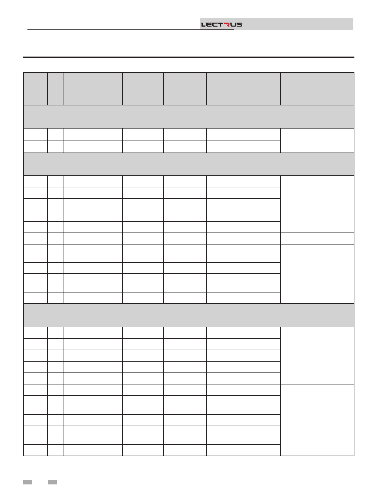
MODEL KW BTU/HR
"FULL
LOAD
AMPS
(FLA)"
ELEMENT(S)
MODULATION
BANK
RELAY(S)
BANK
MINIMUM
CIRCUIT
AMPACITY
(MCA)
DISTRIBUTION BLOCK
LINE SIDE MAXIMUM WIRE
SIZE
240 VAC - 60 Hz - SINGLE PHASE
(L1-L2) 2 conductors Cu or Al with a ground
0015 15 51,182 63 1 x 15 kW 1 x 15 kW - 79
1 x 350 MCM
0030 30 102,364 125 2 x 15 kW 1 x 15 kW 1 x 15 kW 157
208 VAC - 60 Hz - THREE PHASE
(L1-L2-L3) 3 conductors Cu or Al with a ground
0015 15 51,182 42 1 x 15 kW 1 x 15 kW - 52
1 x 2/0 AWG0030 30 102,364 84 2 x 15 kW 1 x 15 kW 1 x 15 kW 105
0045 45 153,546 125 3 x 15 kW 1 x 15 kW 2 x 15 kW 157
0060 60 204,728 167 4 x 15 kW 1 x 15 kW 3 x 15 kW 209
1 x 350 MCM
0075 75 255,911 209 5 x 15 kW 1 x 15 kW 4 x 15 kW 261
0090 90 307,093 250 6 x 15 kW 1 x 30 kW 2 x 30 kW 313 1 x 500 MCM
0105 105 358,275 292 7 x 15 kW 1 x 30 kW
2 x 30 kW -
1 x 15 kW
365
2 x 300 MCM
0120 120 409,457 334 8 x 15 kW 1 x 30 kW 3 x 30 kW 417
0135 135 460,639 375 9 x 15 kW 1 x 30 kW
3 x 30 kW -
1 x 15 kW
469
0150 150 511,821 417 10 x 15 kW 1 x 30 kW 4 x 30 kW 521
480 VAC - 60 Hz - THREE PHASE
(L1-L2-L3) 3 conductors Cu or Al with a ground
0015 15 51,182 18 1 x 15 kW 1 x 15 kW - 23
1 x 2/0 AWG
0030 30 102,364 37 2 x 15 kW 1 x 15 kW 1 x 15 kW 46
0045 45 153,546 55 3 x 15 kW 1 x 15 kW 2 x 15 kW 68
0060 60 204,728 73 4 x 15 kW 1 x 15 kW 3 x 15 kW 91
0075 75 255,911 91 5 x 15 kW 1 x 15 kW 4 x 15 kW 113
0090 90 307,093 109 6 x 15 kW 1 x 30 kW 2 x 30 kW 136
1 x 350 MCM
0105 105 358,275 127 7 x 15 kW 1 x 30 kW
2 x 30 kW -
1 x 15 kW
158
0120 120 409,457 145 8 x 15 kW 1 x 30 kW 3 x 30 kW 181
0135 135 460,639 163 9 x 15 kW 1 x 30 kW
3 x 30 kW -
1 x 15 kW
203
0150 150 511,821 181 10 x 15 kW 1 x 30 kW 4 x 30 kW 226
Table 4A Amp Chart
32
4 Field wiring
Installation & Operation Manual
TM
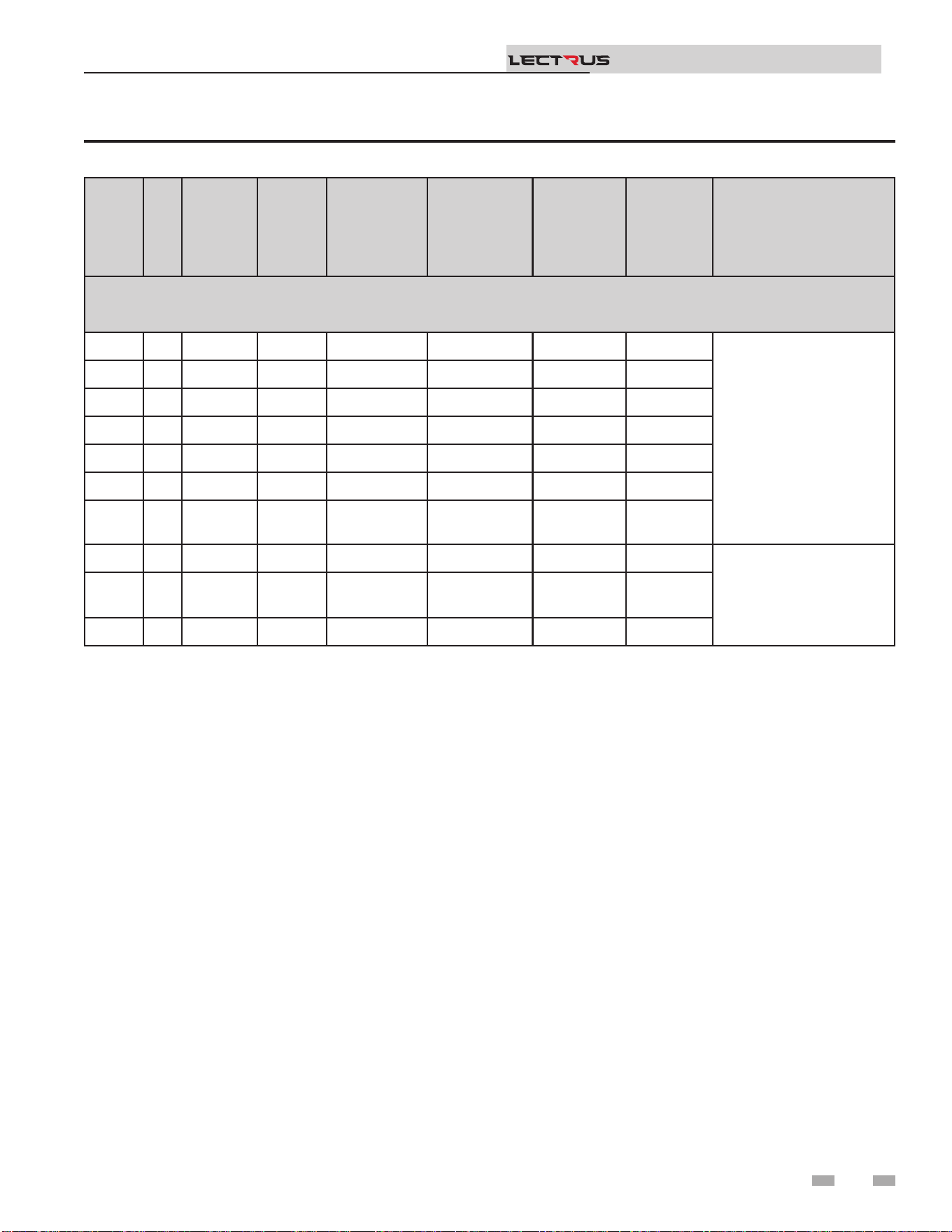
MODEL KW BTU/HR
"FULL
LOAD
AMPS
(FLA)"
ELEMENT(S)
MODULATION
BANK
RELAY(S)
BANK
MINIMUM
CIRCUIT
AMPACITY
(MCA)
DISTRIBUTION BLOCK
LINE SIDE MAXIMUM WIRE
SIZE
600 VAC - 60 Hz - THREE PHASE
(L1-L2-L3) 3 conductors Cu or Al with a ground
0015 15 51,182 15 1 x 15 kW 1 x 15 kW - 18
1 x 2/0 AWG
0030 30 102,364 29 2 x 15 kW 1 x 15 kW 1 x 15 kW 37
0045 45 153,546 44 3 x 15 kW 1 x 15 kW 2 x 15 kW 55
0060 60 204,728 58 4 x 15 kW 1 x 15 kW 3 x 15 kW 73
0075 75 255,911 73 5 x 15 kW 1 x 15 kW 4 x 15 kW 91
0090 90 307,093 87 6 x 15 kW 1 x 30 kW 2 x 30 kW 109
0105 105 358,275 101 7 x 15 kW 1 x 30 kW
2 x 30 kW -
1 x 15 kW
127
0120 120 409,457 116 8 x 15 kW 1 x 30 kW 3 x 30 kW 145
1 x 350 MCM0135 135 460,639 130 9 x 15 kW 1 x 30 kW
3 x 30 kW -
1 x 15 kW
163
0150 150 511,821 145 10 x 15 kW 1 x 30 kW 4 x 30 kW 181
Table 4A Amp Chart (continued)
33
4 Field wiring (continued)
Installation & Operation Manual
TM
MODEL KW
Elements
Size
(KW)
Number of
Element(s)
Number of
Contractors
Number of
Bank(s)
Number of
Element(s)
Per Bank(s)
Number
of Control
Boards
Number of
Modulation
Boards
Number of
Triac Boards /
Fans
240 VAC - 60 Hz - SINGLE PHASE
0015 15 15 1 2 1 1 1 1 1
0030 30 15 2 4 2 1 1 1 1
208 VAC - 60 Hz - THREE PHASE
0015 15 15 1 1 1 1 1 1 1
0030 30 15 2 2 2 1 1 1 1
0045 45 15 3 3 3 1 1 1 1
0060 60 15 4 4 4 1 1 1 1
0075 75 15 5 5 5 1 1 1 1
0090 90 15 6 6 3 2 1 1 2
0105 105 15 7 7 4 2 / 1 1 1 2
0120 120 15 8 8 4 2 1 1 2
0135 135 15 9 9 5 2 / 1 1 1 2
0150 150 15 10 10 5 2 1 1 2
480 VAC - 60 Hz - THREE PHASE
0015 15 15 1 1 1 1 1 1 1
0030 30 15 2 2 2 1 1 1 1
0045 45 15 3 3 3 1 1 1 1
0060 60 15 4 4 4 1 1 1 1
0075 75 15 5 5 5 1 1 1 1
0090 90 15 6 3 3 2 1 1 2
0105 105 15 7 4 4 2 / 1 1 1 2
0120 120 15 8 4 4 2 1 1 2
0135 135 15 9 5 5 2 / 1 1 1 2
0150 150 15 10 5 5 2 1 1 2
600 VAC - 60 Hz - THREE PHASE
0015 15 15 1 1 1 1 1 1 1
0030 30 15 2 2 2 1 1 1 1
0045 45 15 3 3 3 1 1 1 1
0060 60 15 4 4 4 1 1 1 1
0075 75 15 5 5 5 1 1 1 1
0090 90 15 6 3 3 2 1 1 2
0105 105 15 7 4 4 2 / 1 1 1 2
0120 120 15 8 4 4 2 1 1 2
0135 135 15 9 5 5 2 / 1 1 1 2
0150 150 15 10 5 5 2 1 1 2
Table 4B Electrical Recoveries Data
34
4 Field wiring
Installation & Operation Manual
TM
Model
Elements
Fuse
(Amps)
Elements Fuse
Voltage - Class
Elements
Fuse
Quantity
Transformer
Fuse
(Amps)
Transformer
Fuse Voltage -
Class
Transformer
Fuse
Quanitity
Control
Fuse
(Amps)
Controls Fuse
Voltage - Class
Controls
Fuse
Quantity
240 VAC - 60 Hz - SINGLE PHASE
0015 30 300 VAC - T 6 15 300 VAC - T 2 15 250 VAC - K5 1
0030 30 300 VAC - T 12 15 300 VAC - T 2 15 250 VAC - K5 1
208 VAC - 60 Hz - THREE PHASE
0015 60 300 VAC - T 3 15 300 VAC - T 2 15 250 VAC - K5 1
0030 60 300 VAC - T 6 15 300 VAC - T 2 15 250 VAC - K5 1
0045 60 300 VAC - T 9 15 300 VAC - T 2 15 250 VAC - K5 1
0060 60 300 VAC - T 12 15 300 VAC - T 2 15 250 VAC - K5 1
0075 60 300 VAC - T 15 15 300 VAC - T 2 15 250 VAC - K5 1
0090 60 300 VAC - T 18 15 300 VAC - T 2 15 250 VAC - K5 1
0105 60 300 VAC - T 21 15 300 VAC - T 2 15 250 VAC - K5 1
0120 60 300 VAC - T 24 15 300 VAC - T 2 15 250 VAC - K5 1
0135 60 300 VAC - T 27 15 300 VAC - T 2 15 250 VAC - K5 1
0150 60 300 VAC - T 30 15 300 VAC - T 2 15 250 VAC - K5 1
480 VAC - 60 Hz - THREE PHASE
0015 30 600 VAC - T 3 15 600 VAC - T 2 15 250 VAC - K5 1
0030 30 600 VAC - T 6 15 600 VAC - T 2 15 250 VAC - K5 1
0045 30 600 VAC - T 9 15 600 VAC - T 2 15 250 VAC - K5 1
0060 30 600 VAC - T 12 15 600 VAC - T 2 15 250 VAC - K5 1
0075 30 600 VAC - T 15 15 600 VAC - T 2 15 250 VAC - K5 1
0090 60 600 VAC - T 9 15 600 VAC - T 2 15 250 VAC - K5 1
0105 60 600 VAC - T 12 15 600 VAC - T 2 15 250 VAC - K5 1
0120 60 600 VAC - T 12 15 600 VAC - T 2 15 250 VAC - K5 1
0135 60 600 VAC - T 15 15 600 VAC - T 2 15 250 VAC - K5 1
0150 60 600 VAC - T 15 15 600 VAC - T 2 15 250 VAC - K5 1
600 VAC - 60 Hz - THREE PHASE
0015 25 600 VAC - T 3 15 600 VAC - T 2 15 250 VAC - K5 1
0030 25 600 VAC - T 6 15 600 VAC - T 2 15 250 VAC - K5 1
0045 25 600 VAC - T 9 15 600 VAC - T 2 15 250 VAC - K5 1
0060 25 600 VAC - T 12 15 600 VAC - T 2 15 250 VAC - K5 1
0075 25 600 VAC - T 15 15 600 VAC - T 2 15 250 VAC - K5 1
0090 50 600 VAC - T 9 15 600 VAC - T 2 15 250 VAC - K5 1
0105 50 600 VAC - T 12 15 600 VAC - T 2 15 250 VAC - K5 1
0120 50 600 VAC - T 12 15 600 VAC - T 2 15 250 VAC - K5 1
0135 50 600 VAC - T 15 15 600 VAC - T 2 15 250 VAC - K5 1
0150 50 600 VAC - T 15 15 600 VAC - T 2 15 250 VAC - K5 1
Table 4C Fuses
35
5 Start-up
Check/control ll water chemistry
Conduct water quality testing prior
to installing the appliance. Various
solutions are available to adjust water
quality.
IMPORTANT
Boiler Water / Make-Up Water Hardness
and System Volume
e manufacturer recommends the following for properly
lling your boiler with the appropriate water chemistry for
closed loop boilers. Good boiler water quality will help extend
the life of the appliance by reducing the eects of lime scale
build-up and corrosion in closed loop systems.
Pre-Commissioning Cleaning
1. Prior to ll and start-up, isolate the boiler from the system
and ush the entire heating system.
2. Clean the entire heating system with an approved pre-
commissioning cleaner (comparable to Sentinel X300
and Fernox F3) in accordance with the manufacturer’s
recommendation to remove debris and prolong the life of
the pressure vessel.
3. Clean all water ltering devices in the system.
4. Flush the cleaning solution out of the entire system and
rell.
CAUTION
Do not use petroleum-based cleaning or
sealing compounds in the boiler system.
Gaskets and seals in the system may be
damaged. is can result in substantial
property damage.
DO NOT use "homemade cures" or "boiler
patent medicines". Serious damage to
boiler, personnel, and/or property may
result.
CAUTION
Level I Level II
System Volume ≤ 1,000 gal > 1,000 gal
Total Hardness ≤ 12 gpg ≤ 9 gpg
Table 5A Boiler Water and Make-Up Water Total
Hardness Specications
Table 5A provides guidelines for the maximum allowable
hardness levels for both the boiler water and the make-up
water based on the system volume. ere are two (2) levels of
allowable hardness depending on the size of the system. ese
levels are to be chosen based on the smallest boiler size in the
system.
1. Initial system ll must meet the recommended values
of hardness for boiler water / make-up water. is may
require water treatment such as using demineralizers.
2. During the life of the boiler system, the sum of the total
system ll and make-up water quantities should not exceed
three (3) times the system volume.
Additional Boiler Water and Make-Up
Water Specications
Table 5B Additional Boiler Water and Make-Up Water
Specications
Boiler Water Make-Up Water
Total Dissolved Solids ≤ 1,000 ppm < 350 ppm
pH Level 6.5 - 9.5
Chlorides < 150 ppm
Chloride Concentration
1. Do not ll boiler or operate with water containing chlorine
more than 150 ppm.
2. Do not use the boiler to directly heat swimming pool or spa
water.
Iron Concentration
1. Do not ll boiler or operate with water containing iron
more than 0.3 ppm.
Total Dissolved Solids (TDS)
1. Total dissolved solids are all minerals, salts, metals, and
charged particles that are dissolved in water.
2. e greater the amounts of TDS present, the higher the
corrosion potential due to increased conductivity in the
water. Refer to Table 5B for more information.
Installation & Operation Manual
TM
Additional Considerations
1. Monitoring pH, chlorides, TDS, and hardness levels can
prolong the life of the appliance by reducing lime scale
build-up, corrosion, and erosion. Check for leaks to ensure
that fresh water is not entering the system.
2. Continual fresh make-up water will reduce boiler life.
3. Mineral build-up in the pressure vessel reduces heat
transfer, overheats the stainless-steel pressure vessel, and
causes failure.
4. e addition of oxygen carried in by make-up water can
cause internal corrosion in the system components.
5. Leaks in the boiler or piping must be repaired at once to
prevent excessive make-up water. For this purpose, it is
recommended to install a water meter to easily check the
amount of make-up water entering the system. Make-up
water volume should not exceed 5% of the total system
volume per year. NOTE: When make-up water is added,
make sure the chemical additives are added to maintain the
correct level.
3. Consult local water treatment companies for hard water
areas (above the values listed in Table 5A). Hardness levels
that are above the values listed in Table 5A can lead to lime
scale build-up throughout the boiler system.
36

Freeze protection uids
1. Use glycol only if needed for freeze protection uid.
2. Propylene glycol is the recommended freeze protection
uid.
3. Make sure to ush the boiler system before adding glycol.
4. Determine the freeze protection uid quantity using
system water content, following the uid manufacturer's
instructions. Boiler water content is listed in the Boiler
Specications Table on page 6. Remember to include
expansion tank water content.
5. Local codes may require a backow preventer or actual
disconnect from city water supply.
6. When using freeze protection uid with automatic ll,
it is suggested to install a water meter to monitor water
makeup. Freeze protection uid may leak before the water
begins to leak, causing the concentration to drop, which
reduces the freeze protection level.
7. e freeze protection set points may be lowered when
freeze protection uid is used (see the Lectrus Service
Manual).
8. Consult the glycol manufacturer for details on the suggested
mix of glycol and water for the desired freeze protection
level and the de-rate eect it will have on the boiler output.
Test / replace freeze protection uid
1. For systems using freeze protection uids, follow the uid
manufacturer's instructions.
2. Freeze protection uid must be replaced periodically due
to degradation of inhibitors over time.
3. It is recommended to test the glycol concentration annually
and adjust within the desired set points.
Ethylene glycol is toxic. DO NOT use as
your freeze protection uid. Ethylene glycol
has a sweet aroma which children and pets
could mistake as food and ingest, leading
to death.
⚠WARNING
5 Start-up
Dissolved oxygen can have a negative eect on the boiler
system. Oxygen can cause iron oxide to generate iron deposits.
Oxygen may also increase the rate of corrosion on non-
stainless-steel parts of the system. A low pH level combined
with oxygen further enhances its corrosive eects. Aer boiler
installation, check for air leaks in the following areas:
• Suction gasket
• Pump
• Air valve
• O-ring gaskets
Precautions include installing a water meter to evaluate the
freshwater volume entering the system (should be no more
than 5% system volume). Additional volumes of fresh water
could indicate that a leak is present.
CAUTION
Eliminate all system leaks. Continual
fresh makeup water will reduce boiler
life. Minerals can build up in the pressure
vessel, reducing heat transfer, overheating
the pressure vessel, and causing pressure
vessel failure.
Oxygen prevention
Installation & Operation Manual
TM
6. An approved multi-metal corrosion inhibitor (comparable
to Sentinel X100 or Fernox F1) is recommended at the
correct concentration and in the manner recommended by
the manufacturer.
Fill and test water system
1. Fill system only aer ensuring the water meets the
requirements of this manual.
2. Close automatic and manual air vents and boiler drain
valve.
3. Fill to correct system pressure. Correct pressure will vary
with each application.
a. e minimum cold water ll pressure for a system is
12 psi.
b. Pressure will rise when the boiler is turned ON and
system water temperature increases.
4. At initial ll and during boiler startup and testing, check
the system thoroughly for any leaks. Repair all leaks before
proceeding further.
37

5 Start-up (continued)
Check thermostat circuit(s)
1. Disconnect the two external wires connected to each of the
heat/loop demand terminals on the connection board.
2. Connect a voltmeter across these two incoming wires.
Close each thermostat, zone valve, and relay in the external
circuit one at a time and check the voltmeter reading across
the incoming wires.
3. ere should NEVER be a voltage reading.
4. If a voltage does appear under any condition, check, and
correct the external wiring. (is is a common problem
when using 3-wire zone valves.)
5. Once the external thermostat circuit wiring is checked and
corrected if necessary, reconnect the external thermostat
circuit wires to the connection board. Allow the boiler to
cycle.
Purge air from water system
1. Purge air from system:
a. Connect a hose to the purge valve (see purge/drain
valve in the piping diagrams on pages 18 through 23).
Route the hose to an area where water can drain and be
seen.
b. Close the boiler or system isolation valve between the
purge valve and ll connection to the system.
c. Close zone isolation valves.
d. Open the quick-ll valve on the cold-water makeup
line.
e. Open purge valve.
f. Open the isolation valves one zone at a time. Allow
water to run through the zone, pushing out the air.
Run until no noticeable air ow is present. Close
the zone isolation valves and proceed with the next
zone. Follow this procedure until all zones are
purged.
g. Close the quick-ll water valve and purge valve and
remove the hose. Open all isolation valves. Watch that
system pressure rises to correct cold-ll pressure.
h. Aer the system has operated for a while, eliminate
any residual air by using the manual air vents located
throughout the system.
i. If purge valves are not installed in the system, open the
manual air vents in the system one at a time, beginning
with the lowest oor. Close the vent when water
squirts out. Repeat with remaining vents.
2. Open the automatic air vent (diaphragm-type or bladder
type expansion tank systems only) one turn.
3. Open other vents:
a. Starting on the lowest oor, open air vents one at a
time until water squirts out.
b. Repeat with remaining vents.
4. Rell to correct pressure.
Installation & Operation Manual
TM
Final checks before starting the boiler
q Read the Lectrus Service Manual to familiarize yourself
with SMART SYSTEM control module operation. Read
this manual for the proper steps to start the boiler.
q Verify the boiler and system are full of water and all system
components are correctly set for operation.
q Verify the preparation procedures of Section 5 have been
completed.
q Verify electrical connections are correct and securely
attached. Refer to Table 5A - Torque Requirements.
If boiler does not start correctly
1. Check for loose connections, blown fuse or service switch
o?
2. Is boiler water temperature above 230°F (110°C)?
3. Is thermostat set below room temperature?
If none of the above corrects the problem, refer to the
Troubleshooting Section of the Lectrus Service Manual.
Check system and boiler
q Check water piping
1. Check system piping for leaks. If found, shut down the
boiler and repair immediately.
2. Vent any remaining air from the system using manual
vents. Air in the system will interfere with circulation and
cause heat distribution problems and noise.
Minimum Equipment Required for Startup
and Troubleshooting
q Volt-Ohm Meter
q Clamp-On Ammeter
q Megohm Meter
q Torque Wrench - inch lbs
q Torque Wrench - foot lbs
q Personal Protective Equipment
38

5 Start-up
q Inspect all components, external and internal, to assure that
there has been no damage during shipment or installation.
With a Megohm Meter (500VDC minimum), check contactor
load side terminals to ground. If a reading of <1 megohm is
obtained, consult the Factory.
q Remove element access panel(s) and open doors to the
electrical control panel(s). Run an inspection of the
tightness of all electrical connections (IE: at fuse lugs,
power entrance lugs, contactors, heating elements).
All branch circuit connections should be tightened to the
values listed on the component or to the values listed on
Table 5A - Torque Requirements. Torque to avoid component
damage from heat build-up.
is tightness inspection is vital because the vibration during
shipment can oen loosen electrical connections. If this is not
done, damage may occur to component parts when power
is switched on, and those damaged parts will not be covered
under the manufacturer’s Limited Warranty.
Installation & Operation Manual
TM
All POWER supplying boiler should be o
and locked out! with the unit(s) main power
switch(es) OFF and locked out.
⚠WARNING
See Maintenance Section on rechecking the
torque on these components aer an initial
break-in period. Typically, one to two weeks
aer start-up and then at least annually.
NOTICE
Electrical System Checks
q With an ohmmeter, check the resistance between the
phases on the load side of the contactors. Each should read
the same and approximately what is shown on the wiring
diagram.
q Check the electrical panels for loose material, dust and / or
moisture. oroughly vacuum the panels if dust or foreign
materials have accumulated there.
Set space heating operation
Determine controlling sensor
For space heating systems, the temperature control can be
based on one of three sensors: the inlet, outlet, or system
supply sensor. e SMART SYSTEM control is programmed at
the factory to control the temperature of the outlet sensor. e
control will automatically switch to the system supply sensor
once it is connected. If it is desired to base the temperature
control on the inlet sensor, the appropriate parameter must be
changed in the control. See the Lectrus Service Manual for a
detailed explanation of this procedure.
Verify space heat circulator mode
e Space Heating Mode controls both the system pump (if
connected), and the boiler pump. When the SMART SYSTEM
control receives a space heating call for heat, it turns on the
system pump. If the set point is not met, or the system sensor
is not connected, it also turns on the boiler pump. Aer the
space heating call for heat ends, the system pump continues
to run for a short period of time. e system pump can be
programmed to run continuously, except during outdoor
shutdown. Other settings may aect the operation of the
boiler and system pumps, as explained on the following pages.
If the boiler pump was running, it continues to run for a short
period of time as well. e system pump delay is factory set to
30 seconds. e boiler pump delay is factory set to 1 minute. If
dierent delays are desired, the appropriate parameters in the
control must be changed. See the Lectrus Service Manual for a
detailed explanation of this procedure.
Please note that the brackets ([]) denote
screen status.
NOTICE
e NAVIGATION dial may be used during normal operation
to adjust the space heating and tank set point temperatures.
1. From the Status Screen press the NAVIGATION dial.
2. Turn the NAVIGATION dial to select the appropriate set
point.
3. Press the NAVIGATION dial to adjust the temperature.
Rotate the NAVIGATION dial to change the setting.
4. Once the desired temperature is displayed, press the
RIGHT SELECT [SAVE] key.
5. Press the RIGHT SELECT [HOME] key to upload the
changes.
6. If the RIGHT SELECT [SAVE] key is not pressed, the
new settings will be discarded.
Adjust set point temperature(s)
39
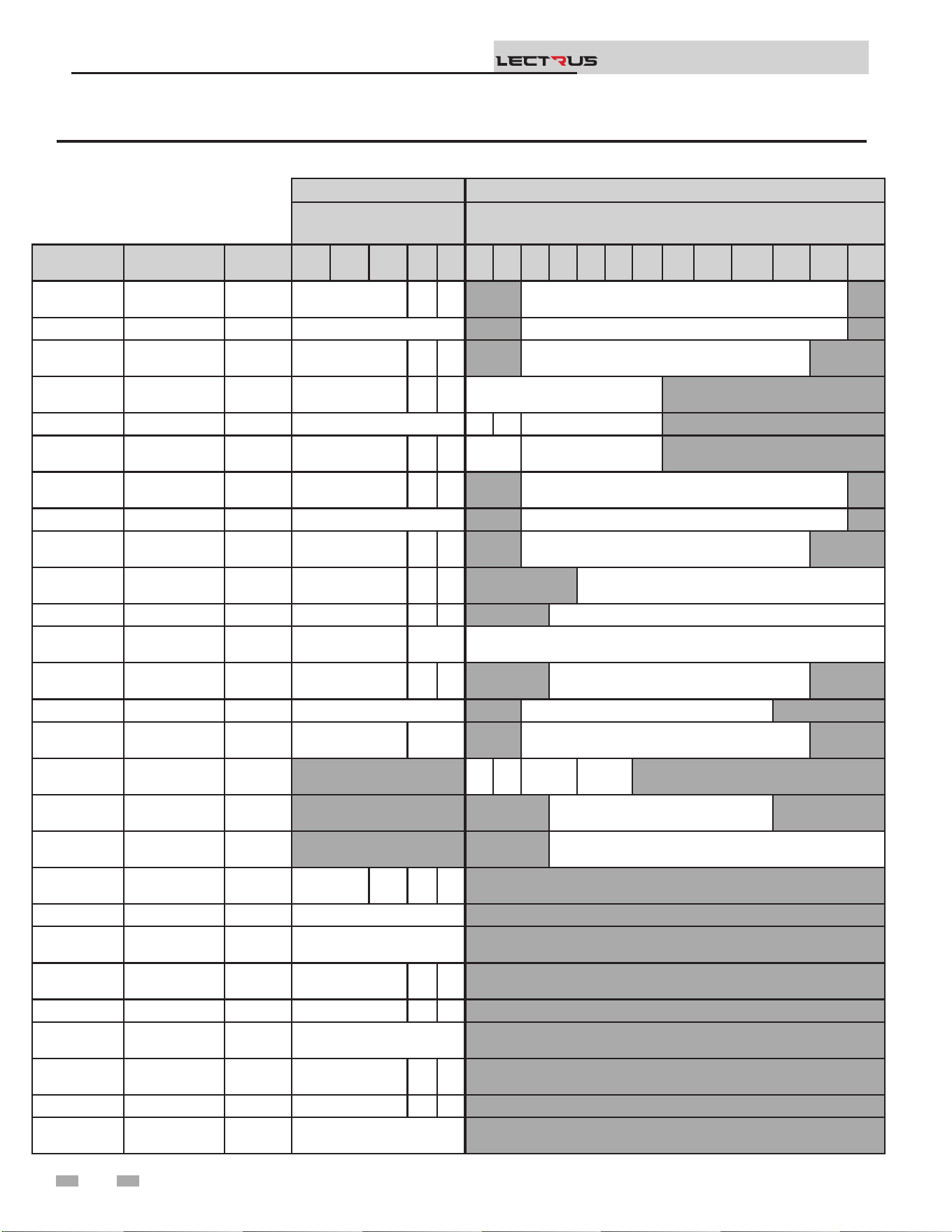
5 Start-up (continued)
Installation & Operation Manual
TM
Table 5A Torque Requirements
LOADSIDE LINESIDE
Torque Per Gauge
(lbs. in)
Torque Per Gauge (lbs. in)
Manufacturer Model Type
14
Ga
12
Ga
10
Ga
8
Ga
6
Ga
10
Ga
8
Ga
6
Ga
4
Ga
2
Ga
0
Ga
00
Ga
000
Ga
0000
Ga
250
MCM
300
MCM
350
MCM
500
MCM
EATON /
BUSSMANN
16023-2 Flat head 20 25 35 275
MARATHON 1402404 Flat head 35 275
FERRAZ
SHAWMUT
67662 Flat head 20 25 35 275
EATON /
BUSSMANN
16021-3 Flat head 20 25 35 120
MARATHON 1403401 Flat head 35 35 40 120
FERRAZ
SHAWMUT
67563 Flat head 20 25 35 50 120
EATON /
BUSSMANN
16023-3 Flat head 20 25 35 275
MARATHON 1403404 Flat head 35 275
FERRAZ
SHAWMUT
67663 Flat head 20 25 35 275
EATON /
BUSSMANN
16375-3 Flat head 20 25 35 500
MARATHON 1453552 Flat head 35 40 45 375
FERRAZ
SHAWMUT
69083 Flat head 35 40 500
EATON /
BUSSMANN
16377-3 Flat head 20 25 35 275
MARATHON 1343596 Flat head 35 275
FERRAZ
SHAWMUT
69143 Flat head 35 40 275
ILSCO TA-0
Hex Socket
head
35 40 45 50
ILSCO TA-250
Hex Socket
head
250
ILSCO TA-250
Hex Socket
head
375
EATON C25DNF340A
Posidrive
head
15 25 40 45
SQUARE D 8910DPA43V02 Flat head 40
TE
CONNECTIVITY
3100-30T10999CG Flat head 40
EATON /
BUSSMANN
T30030-3CR Flat head 20 25 35
MARATHON RT30A3B Flat head 35 40 45
FERRAZ
SHAWMUT
30308T Flat head 35
EATON /
BUSSMANN
T60030-3 Flat head 35 40 45
MARATHON RT60A3B Flat head 35 40 45
FERRAZ
SHAWMUT
30608T Flat head 45
40
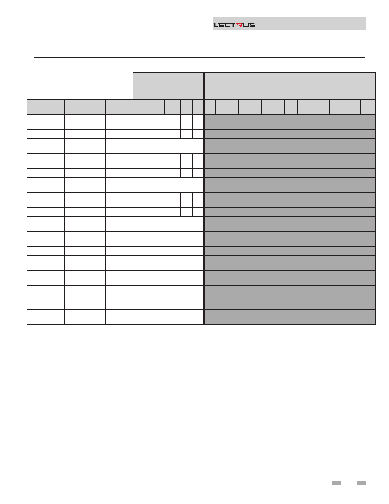
5 Start-up
Installation & Operation Manual
TM
Table 5A Torque Requirements continued
LOADSIDE LINESIDE
Torque Per Gauge (lbs.
in)
Torque Per Gauge (lbs.in)
Manufacturer Model Type
14
Ga
12
Ga
10
Ga
8
Ga
6
Ga
10
Ga
8
Ga
6
Ga
4
Ga
2
Ga
0
Ga
00
Ga
000
Ga
0000
Ga
250
MCM
300
MCM
350
MCM
500
MCM
EATON /
BUSSMANN
T30060-3 Flat head 35 40 45
MARATHON R6T30A3B Flat head 35 40 45
FERRAZ
SHAWMUT
60308T Flat head 35
EATON /
BUSSMANN
T60060-3 Flat head 35 40 45
MARATHON R6T60A3B Flat head 35 40 45
FERRAZ
SHAWMUT
60608T Flat head 45
EATON /
BUSSMANN
T60030-2 Flat head 35 40 45
MARATHON 6T30A2B Flat head 35 40 45
FERRAZ
SHAWMUT
60307T Flat head 35
EATON /
BUSSMANN
H25030-1CR Flat head 35
MARATHON RF30A1B Flat head 25
FERRAZ
SHAWMUT
20306R Flat head 35
EATON /
BUSSMANN
H25030-2CR Flat head 35
MARATHON RF30A2B Flat head 25
FERRAZ
SHAWMUT
20307R Flat head 35
APCOM -
Posidrive
head
30
41

Set domestic hot water (DHW) operation
Verify DHW mode
ere are two (2) modes of operation for DHW. In Normal
Mode, when a DHW demand begins, the control will start
the DHW pump, turn o the boiler pump (if running), and
modulate to bring the outlet temperature to the DHW boiler
set point. e maximum element power may be limited in this
mode if desired.
In Zone Mode it is assumed that the indirect DHW tank is piped
as a zone on the primary loop. When a DHW demand begins,
the control will turn on the DHW pump output, and raise the
system temperature set point to the DHW boiler set point (if
higher). e boiler pump will be turned on. e system pump
may be forced on, forced o, or not changed, depending on
the System Pump Mode selected (reference the Lectrus Service
Manual for details). In this mode, any low temperature zones
(such as radiant heating) may need additional controls to limit
the water temperature sent to those zones.
Set DHW boiler target temperature
When in the DHW Mode, the control will modulate to maintain
the boiler outlet temperature or system supply temperature to
a set point. is set point is set at the factory to 180°F. If a
dierent set point is desired, the appropriate parameter in the
control must be changed. See the Lectrus Service Manual for a
detailed explanation of this procedure.
NOTICE
e internal clock does not adjust for
Daylight Savings Time and therefore, will
require a manual adjustment.
Conguration of the cascade
5 Start-up (continued)
7. Turn the NAVIGATION dial to adjust the minutes. Press
the NAVIGATION dial.
8. Turn the NAVIGATION dial to adjust the month. Press
the NAVIGATION dial.
9. Turn the NAVIGATION dial to adjust the date. Press the
NAVIGATION dial.
10. Turn the NAVIGATION dial to adjust the year. Press the
RIGHT SELECT [SAVE] key.
11. Press the RIGHT SELECT [HOME] key.
Please note that the brackets ([]) denote
screen status.
NOTICE
Set clock
When installed in a Cascade system, the individual controls must
be programmed for cascade operation. is is accomplished by
accessing the control parameters.
Press the [MENU] key for at least ve (5) seconds. Input
the Installer code as described in the Lectrus Service Manual.
Once the control parameters have been accessed, use the
NAVIGATION DIAL to select the “Control Mode” menu.
Press the NAVIGATION DIAL to access these parameters.
Rotate the NAVIGATION dial to select the parameter
“Cascade Address”. Press the NAVIGATION dial to access
this parameter. Each appliance in the Cascade system must be
programmed with its own address. e boiler designated as the
Leader will have an address of 0. e remaining boilers in the
Cascade will be Members and have addresses from 1 - 7. Rotate
the NAVIGATION dial to select the appropriate address. Press
the RIGHT SELECT [SAVE] key.
Press the RIGHT SELECT [HOME] key twice to upload the
address into the control. Repeat this procedure for all boilers in
the Cascade, designating the Leader control and the Member
controls.
Please note that the brackets ([]) denote
screen status.
NOTICE
e SMART SYSTEM control has a built-in clock that it uses
for its night setback feature and for logging events. is clock
must be set when the boiler is installed, and anytime the boiler
has been powered o for more than 4 hours. Use the following
procedure to set the clock:
1. Press and hold the LEFT SELECT [MENU] key for at
least 5 seconds.
2. The display changes to read [PASSWORD],
with four (4) zeros below it. Enter the installer password.
3. Press the RIGHT SELECT [SAVE] key.
4. e display will then show a menu. Select GENERAL by
pressing the dial, then select TIME AND DATE.
5. Press the NAVIGATION dial.
6. Turn the NAVIGATION dial to adjust the hours. Press
the NAVIGATION dial.
e clock is automatically updated whenever a PC is connected
and the Win_Pro-Installer program is started.
Installation & Operation Manual
TM
42

5 Start-up
Installation & Operation Manual
TM
Operating Instructions
With the unit’s control power ON/OFF switch at the back of
the unit on ‘OFF’, close the main power switch(es), and then
turn the ON/OFF switch to ‘ON’.
Alarm and Reset Circuits
If the alarm sounds when the control switch is turned ‘ON’,
depress the alarm silence button if equipped. Check the unit
to make certain that no limit condition exists. e alarm will
sound momentarily on some units when power is initially
applied.
Units with Manual Reset Button(s) may require resetting of the
manual reset switch upon initial application of power, and aer
the interruption or power or the trip-out of a limit control.
Sequencing of Elements Circuits
On units with step controls, the unit will always start with no
steps energized.
As the steps begin cycling on, the LEDs on the modulation
control board (circuit board inside cabinet) will light up one at
a time, indicating that step control is operating properly.
When the outlet water temperature is at or near setpoint, the
controls will cycle to the no-load condition. e steps should
then begin to cycle on as needed, and all the steps may come
on if necessary.
e triac board(s) will modulate up and down as needed up to
two elements to provide a smooth boiler operation to maintain
the set temperature.
Turn o the appliance
To turn the boiler o, simply switch the unit’s control power
ON/OFF switch at the back of the unit to ‘OFF’.
Freeze Protection
e control will turn on the boiler and system pump outputs
whenever the inlet temperature drops below this setting. is is
done to prevent the water in the heat exchanger from freezing.
In addition, the boiler may turn on low power to keep the water
from freezing. Certain low-temperature applications (such as
snow melt) can operate at temperatures around freezing, so
this setting needs to be lowered in these cases. e installer can
adjust the temperature at which the pump outputs are turned
on by accessing Freeze Protection Pump On parameter.
Units with shunt trip disconnects and
remote 120-volt control power may require
turning the control power switch ‘ON’
and activating the 120-volt control power,
before closing the main power switch(es).
NOTICE
43

General
How the boiler operates
e Lectrus uses a carbon steel pressure vessel and electronic
control modules to operate at the capacity needed for
the space heating demand. e modulation control board
powers on the contactors and the Triac board as needed. e
contactors engage to provide power to the resistive heating
elements. e Triac board operates the SCR element as
required.
How the control module operates
e SMART SYSTEM control module receives inputs from
boiler sensors and external devices. e control module
activates and controls the modulation board to regulate heat,
Domestic Hot Water (DHW), and system pumps on and o
as needed. e user programs the module to meet system
needs by adjusting control parameters. ese parameters set
operating temperatures and boiler operating modes. Boiler
operation can be based on boiler outlet water temperature,
boiler inlet water temperature, system temperature, a 0 - 10V
signal, Modbus, or BACnet, depending on the parameter
settings.
Control inputs and outputs
Room thermostat
ere is one (1) heat/loop demand connection available on
this control. is input tells the boiler to provide water for
space heating. is demand connection has its own set point
and outdoor air reset curve.
0 - 10V input (set point or power)
e Lectrus can be controlled by a Building Management
System (BMS) using a 0 - 10 VDC signal. e control can be
congured by the installer to use this signal to either control
set point or element power.
e Lectrus can also be programmed to accept a call for heat
from a 0 - 10V signal, reference the Lectrus Service Manual
for a detailed explanation of this procedure.
DHW priority
e SMART SYSTEM control allows the connection of a DHW
thermostat or tank sensor to the low voltage connection board.
When a tank sensor is connected, the DHW thermostat input
is ignored. When a boiler is programmed for DHW Normal
Mode, the maximum element power can be limited to match
the input rating of the indirect tank coil.
6 Operating information
Installation & Operation Manual
TM
Heating Banks Operation
In general, the banks will enable as follows:
e unit will get to setpoint. For this to happen the modulating
bank will start rst. e “Modulation Control Board” (or
MCB) will enable bank 1 and start the modulation for the Triac
board. It will modulate the board until the Triac reaches 100%
modulation.
If more than one bank is present and modulation needs to
increase, the MCB will reduce the modulation on the Triac to
its minimum and enable the next available bank of elements.
e next bank is not necessarily bank 2. e MCB will evaluate
which bank has run the least as well as which contactor has
been activated less oen.
If the boiler is running at a certain percentage of modulation
for a long time, the MCB will do a bank rotation. e MCB
will evaluate if there is a bank that is not currently running. If
there is no bank available, the current bank will keep running.
If there is a bank available, it will disable the bank that reached
the limit time ON and enabled the next available bank with the
least running time and activation. is rotation is done on a
xed duration.
ere is no actual sequence on which bank will be enabled at
which time. It all depends on running time and actuation, so
the average run time and actuation of each element is the same
over time.
DHW / space heating (SH) cycling
If a DHW call for heat is received while a space heating call is
in progress, and the DHW is in Normal Mode, the control will
start the DHW pump and shut the boiler pump o. e system
pump will remain on. For stand-alone boilers, if the space
heating call is still active while the DHW call is in operation,
the control will wait for 30 minutes (time adjustable by
installer) then it will switch back to the space heating demand.
ere is a timer to switch from space heating to DHW and a
timer to switch from DHW to space heating. e control will
switch back and forth until one of the heat demands end. is
function does not apply to cascade systems.
Programmable controlling sensor
e control module is programmed to use the outlet sensor
as the control sensor by default. If a system supply sensor is
connected, the control automatically uses it as the control
sensor. For stand-alone boilers, the control sensor can be
changed by the installer to the inlet sensor. If the inlet sensor
is chosen as the controlling sensor, it is recommended that
the system supply sensor be installed in the system supply to
provide the best control of the inlet temperature.
44

6 Operating information
Temperature control
Modulation
e Lectrus is capable of modulating heat input from a variable
minimum percentage of the maximum (1-11% depending
on model size) up to 100%. e modulation bank provides a
full range of heating input between each relay bank up to the
maximum.
Ramp delay
For systems with lower ow, the SMART SYSTEM can limit the
KW input (when enabled) when a space heating call for heat
starts, when the set point is controlled by the BMS, or when
switching from a DHW call for heat to a space heating call for
heat. ere are six (6) limits that can be programmed, as well
as six (6) time intervals corresponding to each limit. e sixth
limit will also limit the element power for the rest of the call
for heat.
Gradient limiting
If during operation of the boiler the outlet water temperature
is rising too quickly, the control will reduce the element power
to its lowest setting.
Outdoor air reset
If an outdoor air sensor is connected, the control module will
calculate the set points of the space heating demands based
on the programmed reset curves. e installer can change the
slope of the reset curves by several adjustable parameters. e
user can limit the maximum set points for each demand using
the space heating set points.
Installation & Operation Manual
TM
Protection features
Outlet temperature and temperature rise limiting
e outlet temperature is monitored by the boiler outlet
temperature sensor. When the outlet temperature exceeds
215°F, the unit will reduce its rate. If the outlet water
temperature exceeds 225°F (107°C) the control will shut the
unit down until it cools o.
e control monitors the temperature dierence between
the inlet and the outlet sensor. If this dierence exceeds
70°F (39°C) the control will reduce the modulation. If the
temperature dierence exceeds 80°F (44°C) the control will
shut the unit down. e unit will restart automatically once the
temperature dierence has dropped below 70°F (39°C) and the
minimum o time has expired.
Boost function
If outdoor air reset is active, and any space heating demand
has been active continuously for a set period of time (time
adjustable by installer) and there has been no DHW demands,
the control can increase the set point of that demand by a
xed number of degrees (adjustable by installer). is process
will continue until the space heating demand ends, the set
point reaches the programmed set point or a maximum of
20 increases has occurred. Once the system heat demand is
satised, the set point will revert to the value determined by
the reset curve.
Night setback
e controller may be programmed to reduce the space heating
and DHW set points during certain times each week. Seven
dierent start and stop times may be programmed for the space
heating setback and seven start and stop times for the DHW
setback.
Vacation mode
Vacation Mode is used to lower the Space Heat (SH) and/
or DHW set points much like night setback. e set points
will remain lowered until Vacation Mode is disabled. Night
setback will not function when Vacation Mode is enabled.
Boiler and system pump control
e boiler pump will run whenever the elements are powered,
unless the DHW is programmed for Normal Mode and the
boiler is heating the DHW tank. e boiler pump will run
during Freeze Protection Mode as well. It will continue to
run for a short time aer all elements turn o or the Freeze
Protection Mode ends.
e system pump will run whenever there is a space heating call
for heat, or the boiler goes into Freeze Protection Mode. It may
be programmed to run during a DHW call for heat when the
DHW is programmed for Zone Mode. It will continue to run
for a short time aer the end of the heat demand or the Freeze
Protection Mode. e system pump can be programmed to
run continuously if desired, except during outdoor shutdown
and/or a DHW call for heat.
45

NOTICE
When system return temperatures
are maintained below the dew point,
condensation will form on the inside of the
boiler jacket causing some internal sheet
metal components to rust.
6 Operating information (continued)
Neither this feature, the boiler control module, nor the use of
glycol, eliminates the possibility of freezing. e installation
must still use recognized design, installation, and maintenance
practice to prevent freeze potential for the boiler and system.
e Freeze Protection feature will not work if the appliance
does not have power, is locked out, is in shutdown mode, had a
component failure, or is otherwise prevented from functioning.
e following integral feature of the boiler control module
provides some protection for the boiler only -- not for the
system.
e boiler control module provides a freeze protection feature
with the following attributes:
• Below an inlet temperature of 45°F (7°C), the boiler
pump operates constantly.
• Below an inlet temperature of 37°F (3°C), the
modulation starts.
• Boiler and pumps turn o if boiler water inlet
temperature rises above 45°F (7°C).
Installation & Operation Manual
TM
Monitor external limits
Connections are provided on the connection board for a ow
switch. e SMART SYSTEM will shut o and inhibit the
boiler whenever either the ow switch or low water cuto is
open.
Run-time and alarm outputs
e boiler provides dry contacts for indicating when the boiler
is running, and when it is unable to operate.
Run-time and cycle counting
e control uses timers to monitor the total hours of electric
elements operation. One timer monitors the time the boiler is
in the Space Heating Mode. Another timer monitors the time
the boiler is element power in the DHW Mode.
e control uses counters to monitor the amount of boiler
cycles.
Service reminder
e control can be programmed for service reminder
notication. is notication will become active when either a
set time frame has expired, or a set amount of running hours or
cycles has expired (all adjustable by the installer). e display
will show a Maintenance Required screen. e installer’s name
and phone number can be programmed into the control. is
information will appear on the Maintenance Required screen.
e service reminder notication can be reset or disabled by
the installer.
Error logging
e control will hold in memory the last 10 lockouts. e date
and time of the occurrence will be recorded as well. Only the 10
most current occurrences will be held in memory.
Boiler temperature regulation
Operating temperature (target)
e SMART SYSTEM control module senses water temperature
and regulates boiler rate to achieve a target temperature. e
target temperature can be set between 32°F (0°C) and 215°F
(102°C).
• Target temperature is xed when the outdoor sensor is not
installed.
• Target Temperature is calculated when the outdoor sensor is
connected based on the Outdoor Reset programming. Also,
target is calculated when BMS or BAS is used to control
setpoint based on BMS or BAS programmable parameters.
See the Lectrus Service Manual for more information.
46

6 Operating information
High limit operations
e Lectrus is equipped with adjustable automatic reset and
manual reset high limits. e automatic reset high limit has a
maximum set point of 225°F (107°C) and the manual reset high
limit has a maximum set point of 230°F (110°C).
When the outlet temperature exceeds 225°F (107°C), the
automatic high limit action occurs. e boiler shuts down
until the outlet water temperature cools below 205°F (96°C),
and a 60 second timer has expired. If the outlet temperature
continues to increase, the manual reset high limit action will
occur at 230°F (110°C).
High limit test procedure
1. Turn ON the main power to the boiler by placing the ON/
OFF switch in the ON position.
2. From the Status Screen, press the MENU options and
enter the password.
3. Rotate the dial to access the TEMPERATURE SETTINGS
menu.
4. Rotate the dial to access the Manual Reset (MRHL).
5. Press and rotate the dial to change the setpoint.
6. Set the MRHL below the current outlet temperature.
7. Press the SAVE key on the right.
8. Press HOME. e new parameter will then be saved in the
boiler control.
9. e boiler should now go into lockout for manual reset
high limit.
10. If the current outlet temperature is below the new MRHL
set point, locate the pinhole (SERVICE button) below the
RESET button on the display board. Insert a thin probe
(such as a paper clip) into the hole and press the button
continuously for ve (5) seconds to place the boiler
into Service Mode. In Service Mode, the boiler will then
modulate up to full power.
11. Once the outlet temperature rises to the MRHL setpoint,
the MRHL will function, causing the boiler to shut down
and lock out.
12. Repeat Steps 2 through 7 to adjust the MRHL to its normal
setting.
13. To test the manual reset high limit that is set outside the
unit, locate the “Resideo” manual reset high limit.
14. Using a small screwdriver turn the dial clockwise to its
minimum temperature (130°F).
15. If the outlet temperature is not high enough, repeat step
10.
Please note that the brackets ([]) denote
screen status.
NOTICE
Installation & Operation Manual
TM
Low water cuto protection
1. e SMART SYSTEM control module uses temperature
sensing of both supply and return areas of the pressure
vessel. If the ow rate is too low or the outlet temperature
too high, the control module modulates and shuts the boiler
down. is ensures boiler shutdown in the event of low
water or low ow conditions.
2. In addition, an electronic low water cuto control is
provided.
16. When the outlet temperature reaches the limit, the boiler
will go into lockout for LWCO/MRHL.
17. Using a small screwdriver turn the dial counterclockwise
to set the MRHL level.
47
6 Operating information (continued)
Outdoor reset operation, if used
Target temperature with outdoor reset
is feature improves the system’s eciency as the outdoor
temperature warms up.
See the Lectrus Service Manual to change the settings.
DHW, Night Setback, and Ramp Delay operation with
cascade
For normal mode DHW operation any boiler(s) in the Cascade
can be selected to provide heat for a DHW call. Select a boiler
to be designated as the DHW boiler. Connect the DHW
thermostat or sensor to the terminals on the Connection Board
marked for the corresponding device. When the boiler receives
a DHW call, the Leader control will take that boiler out of the
Cascade sequence. If another boiler is available, the Leader will
start it up to take its place.
e DHW boiler will adjust its set point to the programmed
DHW boiler set point and will adjust its element power to
maintain this. Once the DHW call has been satised, the Leader
control will place that boiler back into the Cascade sequence.
Switching of the boiler between DHW operation and SH
operation when there is a call for both does not occur in
Cascade Mode.
When DHW is programmed for Zone Mode, connect the
DHW thermostat or tank sensor to the Leader boiler. When
a DHW call is received, the Leader will modulate the entire
Cascade to bring the system supply temperature up to the
DHW boiler set point (if higher).
Night Setback operation of the boilers within the Cascade is
available. Programming of the Night Setback will be done
through the Leader boiler. Refer to the Lectrus Service manual
for information regarding Night Setback.
Ramp Delay operation of the boilers as described in the Lectrus
Service Manual is available when the boilers are part of a
Cascade system.
Sequence of the cascade
To equalize the run time of all boilers on the Cascade, the
sequence will automatically be changed at set intervals.
For the rst 24 hours, the sequence will be changed once every
hour. e switching on/o sequence will be as follows:
TIME SWITCHING ON SEQUENCE
Start L-M1-M2-M3-M4-M5-M6-M7
1 hour M1-M2-M3-M4-M5-M6-M7-L
2 hours M2-M3-M4-M5-M6-M7-L-M1
Aer the rst 24 hours, the sequence will change every night
at 2:00 a.m. If a boiler locks out or is used to heat an indirect
DHW tank, it will automatically be given the lowest priority
until 2:00 a.m.
Installation & Operation Manual
TM
(For Hot Water Boiler) Outdoor reset
controller is set at the temperature at which
NOTICE
Reset curve
e reset curves look at outdoor air temperature and adjust the
set points.
Cascade
When multiple boilers are installed, they can be wired together
in a cascade sequence. A maximum of eight boilers can be
controlled from a single control. In this application one boiler
would be designated as the Leader control and all others
would be designated as Member controls. Member 1 can be
congured to take over control of the Cascade should the
Leader stop communicating with the Members. e Leader
control can be programmed to use Lead/Lag or Eciency
Optimization control methods.
Once the Leader boiler receives a call for heat from a room
thermostat, BMS, Modbus, or BACnet the control will
determine what the set point will be. If outdoor air reset is
desired, connect the outdoor air sensor to the terminals on the
Connection Board on the Leader boiler. e set point will be
calculated based on the programmed reset curve parameters.
See the Lectrus Service Manual to program the reset curve. If
outdoor air reset is not desired, do not connect the outdoor
air sensor. A xed temperature set point can be programmed
into the control. See page 36 of this manual to program the set
point.
If the water temperature at the system supply sensor
is less than the set point + oset - dierential, then the
control will initiate a call for heat on the Cascade
(see the Lectrus Service Manual for an explanation of the oset
and dierential). e Leader will energize the lead boiler on the
Cascade. For a new startup this will be the Leader boiler.
the Boiler should operate when the outdoor temperature is
70°F (21°C) (this outdoor reference temperature is adjustable).
e reset ratio is the number of degrees the boiler control
temperature will increase for a 1 degree decrease in outdoor
temperature.
48
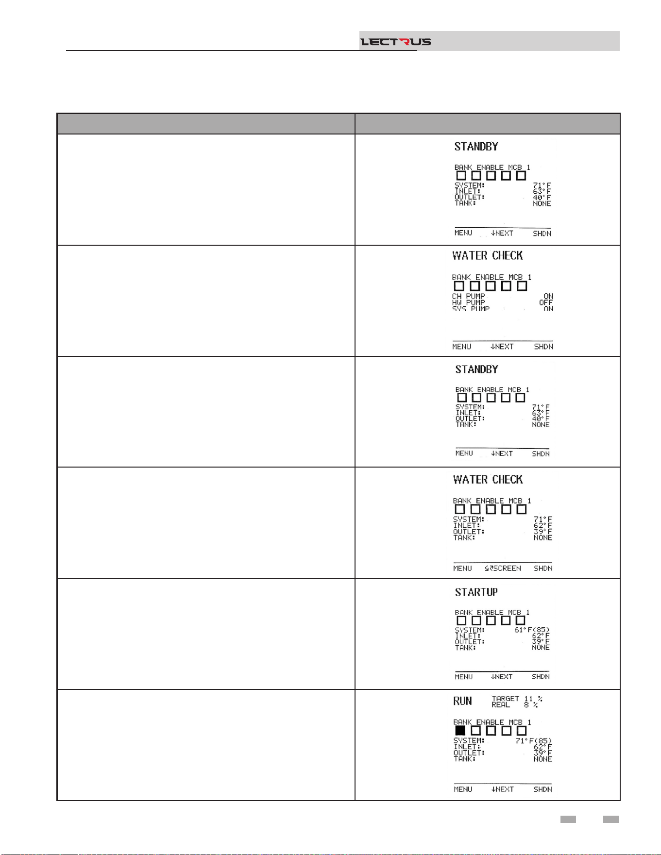
6 Operating information
Sequence of operation
OPERATION DISPLAY
1. At power up, the unit veries all sensors and if everything is
good, it goes into Standby state.
2. Upon a call for heat, the associated pump will become enabled.
3. A few milliseconds after, the low water cuto will become
enabled.
4. The system status will change to “Water Check”. This status is
making sure that a ow is present, and the low water cut o is
working properly. At this state, the unit is waiting for the low
water cuto to close.
5. The control will enable the limit relay and if the temperature is
under the setpoint, it will enable the regulating relay. The runtime
contact will close.
6. Then the unit starts its modulation and enable bank 1 to heat up
the water. The rate is based on setpoint or other commands like
BMS signal.
Installation & Operation Manual
TM
49
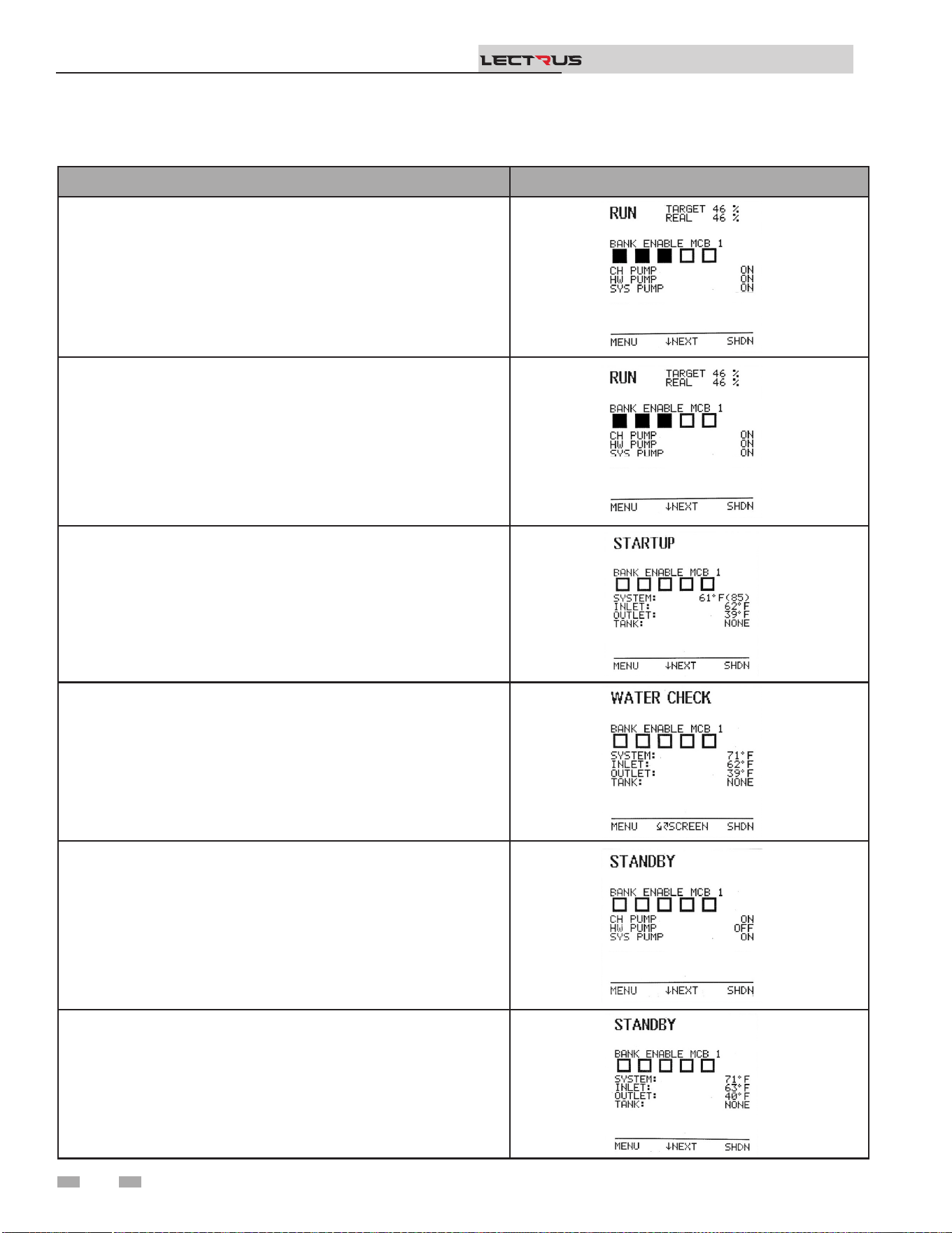
OPERATION DISPLAY
7. If the space heating call for heat is active, and the tank thermostat or
sensor starts a DHW call for heat, the boiler will switch to the DHW
mode. If programmed for normal DHW operation (not as a zone),
the DHW pump will turn on rst, then the boiler pump will turn o
(boiler and DHW pump operation briey overlap to ensure ow is
maintained through the unit). This will divert the boiler’s outlet water
from the heating system and send it to the tank coil instead. The
control will then modulate to maintain the outlet temperature to the
DHW boiler set point.
8. If the boiler is not part of a Cascade, and both the space heating and
DHW calls for heat remain active long enough, the boiler will switch
back and forth between the two heating modes until one of them is
satised.
9. Once both calls for heat are satised, the control will disable the
signal to the modulation board, disabling the regulating relay.
10. Then it will disable the limit relay and the status goes back to Water
Check.
11. Any pumps that are running will continue to run for their respective
pump delay times before turning o, unless programmed to remain
on continuously.
12. In Standby, ready to start a new cycle.
Sequence of operation
6 Operating information (continued)
Installation & Operation Manual
TM
50

Sequence of operation
6 Operating information
Installation & Operation Manual
TM
Activation of Heating Element
Circuits
Contactors
e heating elements are energized by a power source that is
supplied through the contacts of a contactor. e contactor is
activated (on a call for heat) by the closure of a temperature
switch or by a contact in the step control circuit.
Fuses
All power leads to the elements are fused. e fusing is on the
line side of the contactors.
Sequencing Controls
e heating elements are driven directly from the power
contactors. ese are energized by the modulation control
board depending on the requested power sent by the boiler
control. e modulation control board will sequence the
contactors as needed. e boiler control evaluates the request
for heat from the space heat, direct hot water input or
the building management system 0-10V input. It will also
evaluate the need to service the heat request depending on the
temperature of the water and send the requested power to the
modulation board if the water needs to be heated.
e safety limit devices (Flow switch, low water cuto, manual
reset high limit) interrupt the power to the contactor coil
circuits.
Startup logic
e boiler control will monitor the heat demand as well as the
temperature of the water. If a demand is present and the water
temperature is lower than setpoint then the unit will start. e
boiler control will enable the appropriate pump(s) and then
the low water cuto. It will verify if the low water cuto is in
correct state as well as the presence of ow. Aer the boot time
for the LWCO and validating that the inputs are good, the unit
will energize the limit relay and slightly aer the regulating
controls from the modulation control board. When this is
completed, the boiler control will send a power request to the
modulation control board and the unit will start servicing the
heat demand.
Modulation logic
Depending on the power requested by the boiler control, the
modulation control board will enable certain contactor to heat
the water. It will rst enable bank 1 and start modulation of
the power. e power will gradually increase as the request
increases until it reaches full modulation. If the power request
decreases or stabilizes, the modulation control board will
follow the request.
Bank Rotation
As the temperature increases, the boiler will modulate to stay
at temperature. If for any reason the setpoint is not met for a
certain duration, the MCB will verify if there is any available
contactor to enable so the unit is not running only one set of
elements/banks all the time. is function will help averaging
the running hours of all the elements.
Boost Feature
As the boiler runs and the boiler control maintains a
temperature close to setpoint, the modulation may not be at
100%. In that case, the boiler control will, aer some time, try
to reach temperature by increasing the modulation. is boost
feature allows the boiler to meet the setpoint and help for the
unit to not run continuously.
After the demand
When the demand is removed or the temperature reaches
setpoint, the unit will need to go back to standby. Before doing
so, the boiler control will reduce the power demand to 0. When
the modulation control board receives a power demand of 0, it
will disable the contactor and stop the modulation on bank 1.
e boiler control will then disable the regulating control. Aer
a certain time, the boiler control will disable the limit control,
then the low water cuto. e unit will now be in standby.
As the power request increase, the MCB will eventually reach
full modulation with Bank 1 (except for 15kW units since
they only have bank 1). If more banks are available with the
boiler, the MCB will enable them and reduce the modulation
from bank 1 to its minimum. As power requests increase, the
modulation from bank 1 will increase. To evaluate if a bank can
be enabled, the MCB will rst look at the number of actuations
the contactor has cycled. If one or more contactors has the
same count of actuation, the MCB will look at the run time for
those contactor/elements. It will then select the one with the
least runtime. If one or more have the same runtime, it will
then select the next available bank.
As the temperature increases, the boiler control monitors the
temperature of the output sensor or tank sensor depending on
the demand type. e demand will have to reach setpoint plus
oset.
51
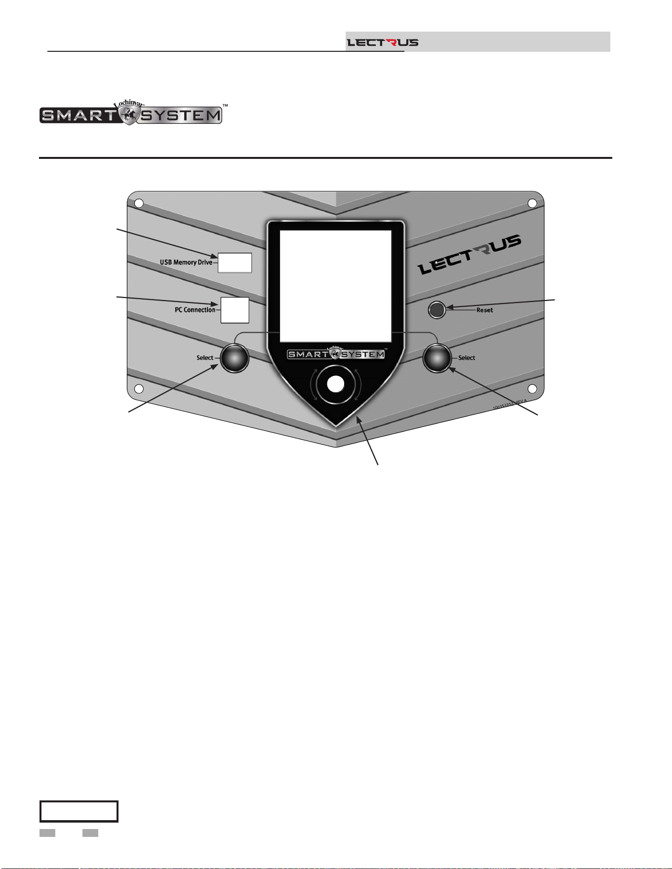
Access modes
User
e user can adjust space heating and tank target temperatures
by pressing the NAVIGATION dial when “$SETPOINTS” is
ashing at the bottom of the display. e date and time, and the
temperature units can also be changed.
Installer
Most parameters are available only to the installer, accessible by
entering the installer password, see the Lectrus Service Manual.
Saving parameters (reference the Parameter Table in the
Lectrus Service Manual)
6 Operating information (continued)
Lectrus control module
Figure 6-1 Control Panel
Use the control panel (FIG. 6-1) to set temperatures, operating conditions, and monitor boiler operation.
Please note that the brackets ([]) denote
screen status.
NOTICE
To save parameters and exit programming:
Press the RIGHT SELECT [SAVE] key and then press the
RIGHT SELECT [HOME] key.
To enter a parameter and continue programming:
Press the RIGHT SELECT [SAVE] key 1 time to return to
the parameter listings; press again to return to the menu
listings. Remember to press the RIGHT SELECT [HOME]
key when nished programming to save the changes made.
See the Lectrus Service Manual for a detailed description of
parameters and access modes.
e information on the bottom of the display shows the functions of the two SELECT keys (on either corner), and the
NAVIGATION dial (in the center):
MENU = Le SELECT Key
SETPOINTS = NAVIGATION Dial - Pressing Down
SHDN = Right SELECT Key
Installation & Operation Manual
TM
2000668360 00
USB
DRIVE
PC
CONNECTION
LEFT
SELECT
KEY
NAVIGATION
DIAL
RIGHT
KEY
SELECT
RESET
SWITCH
52
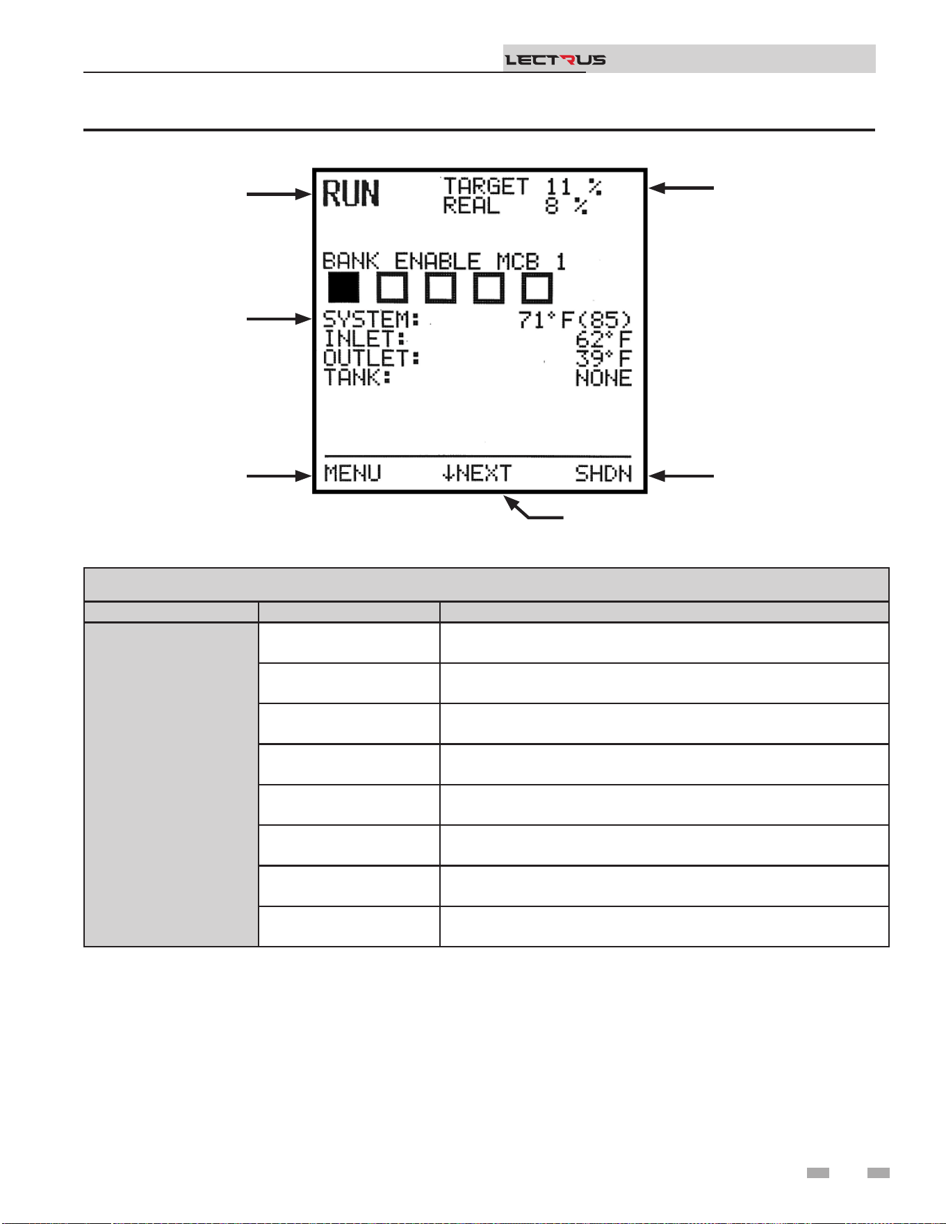
6 Operating information
Status Display Screens
NOTE: All screens show modulation status, heat demands, lockout/blocking, bank status, and so keys.
Section Display Description
A
(Boiler Status)
STANDBY
e unit has not received a call for heat from a remote thermostat nor
has it received a call for heat from a DHW thermostat.
WATER CHECK e unit is checking all safety circuits including the presence of water.
STARTUP e unit is enabling the regulating and limiting device.
RUN e unit is running and heating water.
SHUTDOWN e unit has been placed in the OFF position.
SETPOINT MET e controlled temperature has exceeded its set point and its oset.
BLOCKING
e unit has detected a condition that has temporarily interrupted the
current call for heat.
BANK ENABLE
e number of squares indicates the number of banks available. If the
bank is ON, the square is lled. If the bank is OFF, the square is empty.
Figure 6-2 Status Display Screen
Installation & Operation Manual
TM
(NAVIGATIONAL DIAL)
A
F
E
D
C
B
(BOILER STATUS)
(OPERATIONAL
INFORMATION)
(LEFT SELECT
KEY)
(RIGHT SELECT
KEY)
(MODULATION)
53

6 Operating information (continued)
Status Display Screens (cont’d)
NOTE: All screens show boiler status, heat demands, lockout/blocking, pump status, and so keys.
Section Display Description
B
(Operational
Information)
HOME SCREEN
- System Temperature
- Inlet Temperature
- Outlet Temperature
- Tank Temperature
BMS SCREEN
- BMS in
- Rate out
- Sys pump speed
- BLR pump speed
PUMP STATUS
- BLR pump
- DHW pump
- SYS pump
HISTORY SCREEN
- SH Runtime
- SH Cycles
- DHW runtime
- DHW cycles
- Power Hours
FAULT SCREEN
Last 10 faults: (Press the navigation dial to go through faults)
- Fault name
- Date
- Time
C
(Le Select Key)
MENU Press the le select key to access the installer menu.
D
(Navigation Dial)
NEXT SCREEN Rotate the knob to access the dierent screens
E
(Right Select Key)
SHDN
Press and hold the Right key to shut down the unit or to turn it back
ON.
SAVE
Within the installer menus, the button will be used to save the
current value.
F
(Modulation)
TARGET Target modulation per the Boiler Control
REAL Real modulation feedback from the MCB
Installation & Operation Manual
TM
54
7 Maintenance
Installation & Operation Manual
TM
Follow the Service and maintenance procedures given throughout this manual and in component literature
shipped with the boiler. Failure to perform the service and maintenance could result in damage to the boiler or
system. Failure to follow the directions in this manual and component literature could result in severe personal
injury, death, or substantial property damage.
e boiler should be inspected annually only by a qualied service technician. In addition, the maintenance and
care of the boiler designated in Table 7A and Table 7B, and explained on the following pages must be performed
to assure maximum boiler eciency and reliability. Failure to service and maintain the boiler and system could
result in equipment failure.
Electrical shock hazard – Turn o power to the boiler and disconnect the main feed before any service operation
on the boiler except as noted otherwise in this instruction manual. Failure to turn o electrical power could
result in electrical shock, causing severe personal injury or death.
Address reported problems
1. Inspect any problems reported by the owner and correct
before proceeding.
Inspect boiler area
1. Verify that boiler area is free of any combustible materials,
gasoline and other ammable vapors and liquids.
Inspect boiler interior
1. Open the top panel and front door and inspect the interior
of the boiler.
2. Vacuum any sediment from inside the boiler and
components. Remove any obstructions.
Eliminate all system or boiler leaks.
Continual fresh makeup water will reduce
boiler life. Minerals can build up in sections,
reducing heat transfer, overheating pressure
vessel, and causing pressure vessel failure.
Leaking water may also cause severe property
damage and risk of electrocution.
1. Inspect all water piping and verify to be leak free.
2. Look for signs of leaking lines and correct any problems
found.
Check all piping for leaks
⚠WARNING
⚠WARNING
⚠WARNING
⚠
WARNING
⚠ DANGER
If this boiler may be frozen, immediately shut off power to the appliance and contact the factory for further
instructions. Operation when the pressure vessel, internal pipes, or pressure relief valves are frozen, will result
in internal pressure build-up and a deadly steam explosion. Neither the Freeze Protection feature of the boiler
control module, nor the use of glycol eliminates the possibility of freezing.
Maintenance and annual startup
Table 7A Service and Maintenance Schedules
Service technician
(see the following pages for instructions)
Annual Startup
General:
• Address reported problems
• Inspect interior; clean and vacuum if necessary
• Check for leaks (water)
• Check system water pressure/system/piping/expansion tank
• Check ll water meter
• Test boiler water. When test indicates, clean system water with approved system
restorer following manufacturer’s information
• Check control settings
• Check wiring and connections
55

Check water system
1. Verify all system components are correctly installed and
operational.
2. Check the cold ll pressure for the system. Verify it is
correct (must be a minimum of 12 psi (82.7 kPa)).
3. Watch the system pressure as the boiler heats up (during
testing) to ensure pressure does not rise too high.
Excessive pressure rise indicates expansion tank sizing or
performance problem.
4. Inspect automatic air vents and air separators. Remove
air vent caps and briey press push valve to ush vent.
Replace caps. Make sure vents do not leak. Replace any
leaking vents.
Check expansion tank
1. Expansion tanks provide space for water to move in
and out as the heating system water expands due to
temperature increase or contracts as the water cools.
Tanks may be open, closed or diaphragm or bladder type.
See Section 3 - Hydronic Piping for suggested best location
of expansion tanks and air eliminators.
Check ll water meter
1. Check ll water meter for water usage. If the amount
exceeds 5% of your system volume, you could have a
leak. Have the system checked for leaks and repaired by a
qualied service technician.
Test boiler water
1. Test boiler water. Reference section 5 of the Lectrus
Installation and Operation Manual for guidelines. When
test indicates, clean system water with approved system
restorer following the manufacturer’s information.
7 Maintenance (continued)
Safety relief valves should be re-inspected
AT LEAST ONCE EVERY THREE YEARS,
by a licensed plumbing contractor or
authorized inspection agency, to ensure
that the product has not been aected by
corrosive water conditions and to ensure
that the valve and discharge line have not
been altered or tampered with illegally.
Certain naturally occurring conditions may
corrode the valve or its components over
time, rendering the valve inoperative. Such
conditions are not detectable unless the
valve and its components are physically
removed and inspected. is inspection
must only be conducted by a plumbing
contractor or authorized inspection agency
– not by the owner. Failure to re-inspect the
boiler relief valve as directed could result in
unsafe pressure buildup, which can result in
severe personal injury, death, or substantial
property damage.
Following installation, the valve lever must
be operated AT LEAST ONCE A YEAR to
ensure that waterways are clear. Certain
naturally occurring mineral deposits may
adhere to the valve, rendering it inoperative.
When manually operating the lever, water
will discharge, and precautions must be
taken to avoid contact with hot water and to
avoid water damage. Before operating lever,
check to see that a discharge line is connected
to this valve directing the ow of hot water
from the valve to a proper place of disposal.
Otherwise, severe personal injury may result.
If no water ows, valve is inoperative. Shut
down the boiler until a new relief valve has
been installed.
2. Aer following the above warning directions, if the relief
valve weeps or will not seat properly, replace the relief
valve. Ensure that the reason for relief valve weeping is
the valve and not over-pressurization of the system due to
expansion tank waterlogging or under-sizing.
⚠WARNING
⚠WARNING
Check boiler relief valve
1. Inspect the relief valve and li the lever to verify ow.
Before operating any relief valve, ensure that it is piped with
its discharge in a safe area to avoid severe scald potential.
Read Section 3 - Hydronic Piping before proceeding
further.
Installation & Operation Manual
TM
56
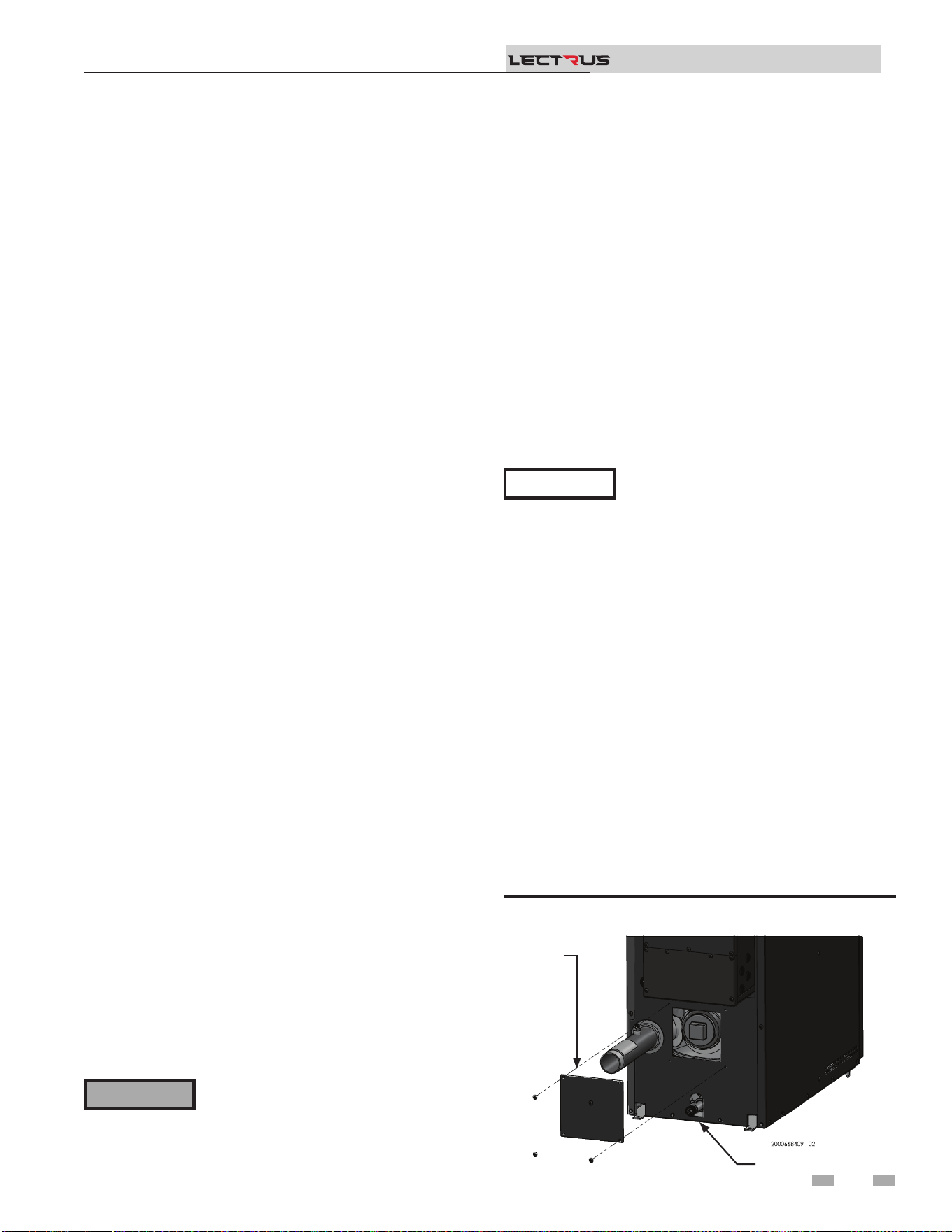
Review with owner
1. Review the Lectrus User’s Information Manual with the
owner.
2. Emphasize the need to perform the maintenance schedule
specied in the Lectrus User’s Information Manual (and in
this manual as well).
3. Remind the owner of the need to call a licensed contractor
should the boiler or system exhibit any unusual behavior.
4. Remind the owner to follow the proper shutdown procedure
and to schedule an annual start-up at the beginning of the
next heating season.
7 Maintenance
Installation & Operation Manual
TM
Electrical System Maintenance
1. Clean the control cabinets periodically (as oen as needed)
to keep both the interior and the exterior free of dust,
moisture, and foreign matter. e interior cleaning of the
electrical panels must be done with the POWER OFF!
NOTICE
For units supplied with control cabinet
cooling fans, the condition of the fan lter
must be periodically checked, and the lters
cleaned or replaced as necessary.
2. With the POWER OFF, periodically check the tightness of
electrical connections; particularly at power entrance lugs,
fuses (line side) and contractors (load side). is should be
done at time of commissioning, at 7 – 14 days thereaer
and at least annually. Replace any components that show
signs of heat damage (IE: discoloration, charring, melted
insulation, etc.). See Table 5A - Torque Specications.
3. Inspect the condition of the contactors. Look for burned
or corroded contacts or overheated coils and wires. If the
contactors chatter or hum during operation, they should
be either disassembled and cleaned to remove dust or
other foreign material in the mechanism or replaced.
4. Inspect the heating elements. Make sure that the terminal
contacts are tight, clean, and corrosion-free.
5. Check all the wiring throughout the unit for frayed or
brittle insulation. Replace any wiring showing insulation
degradation.
Check all boiler wiring
1. Inspect all boiler wiring, making sure wires are in good
condition and securely attached.
Check control settings
1. Set the SMART SYSTEM control module display to
Parameter Mode and check all settings. See Section 1 of
the Lectrus Service Manual. Adjust settings if necessary.
See Section 1 of the Lectrus Service Manual for adjustment
procedures.
2. Check settings of external limit controls (if any) and adjust
if necessary.
Perform start-up and checks
1. Start boiler and perform checks and tests specied in
Section 5 - Start-up.
2. Verify cold ll pressure is correct and that operating
pressure does not go too high.
The boiler contains insulating fiber
materials. Use care when handling these
materials per instructions in the Lectrus
Service Manual. Failure to comply could
result in severe personal injury.
⚠WARNING
Cleaning boiler pressure vessel
1. Shut down boiler:
• Follow the “To Turn O Appliance” instructions
for the boiler in Section 5 - Startup.
• Do not drain the boiler unless it will be exposed to
freezing temperatures. If using freeze prevention uids
in the system, do not drain.
2. Allow time for the boiler to cool to room temperature if it
has been element power.
3. Remove the screws securing the inspection opening cover
plate on the back of the unit (see Figure 7-1).
4. Unscrew the 3" NPT brass plug from the opening.
5. Use a vacuum cleaner to remove any accumulation inside
the boiler. Do not use any solvent.
6. Using a clean cloth dampened with warm water, wipe out
the inside. Rinse out debris with a low-pressure water
supply.
7. Allow the pressure vessel to thoroughly dry.
8. Reassemble the unit. Conrm that the pressure vessel is
lled, checked for leaks, and that any air is purged.
9. Resume operation.
Figure 7-1 Remove inspection cover
DRAIN
REMOVE
COVER
57

7 Maintenance (continued)
Installation & Operation Manual
TM
Owner maintenance
(see the Lectrus User’s Information Manual for instructions)
Daily
• Ensure valves, connections, piping, gaskets, etc. are not leaking
• Check pressure/temperature gauge
Weekly
• Verify that boiler water properties are within desired parameters
7-14 Days
after
STARTUP
• Re-torque screws on distribution, fuse blocks and contactors to their specied torque (typically
45 – 50 in – lbs.)
• Re-torque any bolts on copper distribution from disconnects or circuit breakers to typical torque
values for the size of bolt used.
• Send Startup form to Lochinvar.
Monthly to
Every Six
Months
• Check for any heating element gasket leaks
• Clean cooling fans to maintain proper air ow
• Check fuses and heating elements with an ohm meter for proper values.
• Look for signs of overheating on fuses, fuse blocks, contractors, and wires. Any discolored,
charred, or melted components should be replaced. Ensure all screws are torqued to their proper
values for any replaced components.
• Check boiler piping (water) for leaks
• Operate relief valve
Annually
• Inspect interior of tank for sludge or scale. Clean tank and modify water treatment chemistry as
necessary.
• Replace brittle element gaskets, valve gaskets and as necessary.
• Re-torque ALL distribution, fuse block and contactor screws to the proper value.
• Re-torque any bolts on copper distribution from disconnects or circuit breakers to typical torque
values for the size of bolt used.
End of
season
months
• Shut boiler down (unless boiler used for domestic hot water)
Periodically
• Test low water cuto
• Reset button (low water cuto)
Typical Preventative Maintenance List
MAIN POWER MUST BE TURNED OFF
TO DO ELECTRICAL CHECKS!
⚠WARNING
NOTICE
is list may not be all inclusive! Read
and understand entire ‘Lectrus Service
Manual’ and take into consideration any
modications and / or optional equipment
for this unit:
Table 7B Service and Maintenance Schedules
58
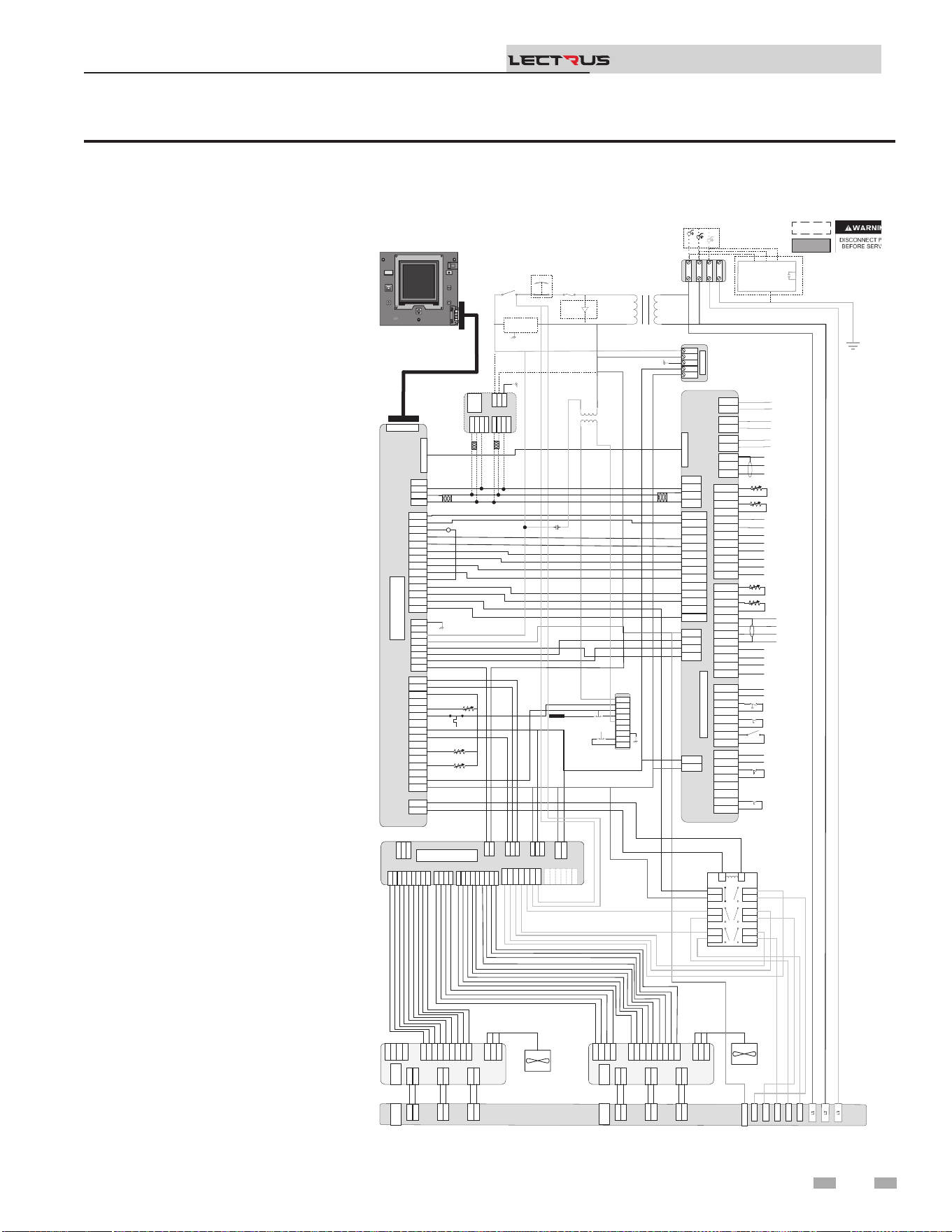
Figure 8-1 Wiring Diagram - 208V, 3 Phase (A)
8 Diagrams
Installation & Operation Manual
TM
Notes:
1. All wiring must be installed in
accordance with local, state,
provincial and national code
requirements per either N.E.C in
USA or C.S.A in Canada.
2. If any original equipment wire
was supplied with the appliance
must be replaced, it must be
replaced with wire having the
same wire gauge (AWG) and
rated for a minimum of 105°C.
Exceptions: Any wiring listed on
the replacement parts list and
ribbon cable must be purchased
from the factory. Use of a non-
approved factory replacement
harness lead or ribbon cable
can lead to operational
problems which could result in
non-repairable damage to the
integrated controller or other
components.
3. Actual connector block locations
may vary from those shown
on diagrams. Refer to actual
components for proper connector
block locations when using
diagrams to trouble shoot the
unit.
+V
-V
GND
N
L
+V
-V
GND
N
L
PSU
+V
-V
GND
N
L
24VDC PSU
J2-1
J2-2
J2-3
J3-1
J3-2
J3-3
J3-4
J3-5
J3-6
X7-RIBBON
X4-1
X4-2
X4-3
X4-4
X4-5
X4-6
X4-7
X4-8
X4-9
X4-10
X4-11
X4-12
X4-13
X4-14
X4-1
X4-2
X4-3
X4-4
X4-5
X4-6
X4-7
X4-8
X4-9
X4-10
X4-11
X4-12
X4-13
X4-14
X9-1
X9-2
X9-3
X9-4
X9-1
X9-2
X9-3
X9-4
X5-1
X5-2
X5-3
X5-4
X5-5
X5-6
X5-7
X5-8
X5-9
X5-10
X5-11
X5-12
X5-13
X5-14
X5-15
X5-16
X5-1
X5-2
X5-3
X5-4
X5-5
X5-6
X5-7
X5-8
X5-9
X5-10
X5-11
X5-12
X5-13
X5-14
X5-15
X5-16
X1-1
X1-2
X1-3
X1-4
X1-5
X1-6
X1-7
X1-8
X1-1
X1-2
X1-3
X1-4
X1-5
X1-6
X1-7
X1-8
X2-1
X2-2
X2-1
X2-2
BIC
X6 RIBBON
X7-RIBBON
X4-1
X4-2
X4-3
X4-4
X4-5
X4-6
X4-7
X4-8
X4-9
X4-10
X4-11
X4-12
X4-13
X4-14
X9-1
X9-2
X9-3
X9-4
X5-1
X5-2
X5-3
X5-4
X5-5
X5-6
X5-7
X5-8
X5-9
X5-10
X5-11
X5-12
X5-13
X5-14
X5-15
X5-16
X1-1
X1-2
X1-3
X1-4
X1-5
X1-6
X1-7
X1-8
X2-1
X2-2
BOILER INTERGRATED CONTROL
(BIC)
X6 RIBBON
CN5-1
CN5-2
CN5-3
CN5-1
CN5-2
CN5-3
DHW1
DHW2
DHW1
DHW2
SYS1
SYS2
SYS1
SYS2
BLR1
BLR2
BLR1
BLR2
CN3-1-1
CN3-1-2
CN3-1-3
CN3-1-4
CN3-1-5
CN3-1-6
CN3-1-7
CN3-1-8
CN3-1-1
CN3-1-2
CN3-1-3
CN3-1-4
CN3-1-5
CN3-1-6
CN3-1-7
CN3-1-8
CN3-2-1
CN3-2-2
CN3-2-3
CN3-2-4
CN3-2-5
CN3-2-6
CN3-2-7
CN3-2-8
CN3-2-1
CN3-2-2
CN3-2-3
CN3-2-4
CN3-2-5
CN3-2-6
CN3-2-7
CN3-2-8
J1-1
J1-2
J1-3
J1-4
J1-1
J1-2
J1-3
J1-4
CN9-1
-
CN9-3
CN9-4
CN9-1
CN9 2
CN9-3
CN9-4
CN4-1
CN4-2
CN4-3
CN4-4
CN4-5
CN4-6
CN4-7
CN4-8
CN4-9
CN4-10
CN4-11
CN4-12
CN4-13
CN4-14
CN4-1
CN4-2
CN4-3
CN4-4
CN4-5
CN4-6
CN4-7
CN4-8
CN4-9
CN4-10
CN4-11
CN4-12
CN4-13
CN4-14
Connecon Board
CN6 RIBBON
DHW Pump (120VAC 0.75 Max)
System Pump (120VAC 0.75 Max)
Boiler Pump (120VAC 0.75 Max)
Shield
A
B
Run Time Contacts
Low Pressure Switch
Flow Switch
Demand Enable
Alarm Contacts
DHW Demand
External LWCO
120V
24VAC
LWCO
Test
Reset
Probe
J6-1
J5-1
J6-1
J5-1
J2-1
J1-1
J2-1
J1-1
J4-1
J3-1
J4-1
J3-1
TRIAC 2
TRIAC 1
J6-1
J5-1
J6-1
J5-1
J2-1
J1-1
J2-1
J1-1
J4-1
J3-1
J4-1
J3-1
J8-9
J8-8
J8-7
J8-6
J8-5
J8-4
J8-3
J8-2
J8-1
J8-9
J8-8
J8-7
J8-6
J8-5
J8-4
J8-3
J8-2
J8-1
J7-4
J7-3
J7-2
J7-1
J7-4
J7-3
J7-2
J7-1
J9-1
J9-2
J9-3
J9-1
J9-2
J9-3
J6-1
J5-1
J6-1
J5-1
J2-1
J1-1
J2-1
J1-1
J4-1
J3-1
J4-1
J3-1
J8-9
J8-8
J8-7
J8-6
J8-5
J8-4
J8-3
J8-2
J8-1
J7-4
J7-3
J7-2
J7-1
J9-1
J9-2
J9-3
J6-1
J5-1
J2-1
J1-1
J4-1
J3-1
TRIAC 1
J8-9
J8-
8
J8-7
J8-6
J8-5
J8-4
J8-3
J8-2
J8-1
J8-9
J8-
8
J8-7
J8-6
J8-5
J8-4
J8-3
J8-2
J8-1
J7-4
J7-
3
J7-2
J7-1
J7-4
J7-
3
J7-2
J7-1
J9-1
J9-2
J9-3
J9-1
J9-2
J9-3
J6-1
J5-1
J6-1
J5-1
J2-1
J1-1
J2-1
J1-1
J4-1
J3-1
J4-1
J3-1
TRIAC 2
J8-9
J8-
8
J8-7
J8-6
J8-5
J8-4
J8-3
J8-2
J8-1
J7-4
J7-
3
J7-2
J7-1
J9-1
J9-2
J9-3
J6-1
J5-1
J2-1
J1-1
J4-1
J3-1
TRIAC 2
14
8
6
10
12
120Neu
R6
R6 LWCO RELAY
3
4
7
8
11
12
5
6
9
10
13
14
1
2
3
4
7
8
11
12
5
6
9
10
13
14
1
2
LR
3
4
7
8
11
12
5
6
9
10
13
14
1
2
LR
GND
J3-1
J3-2
J3-3
J3-4
J3-5
J3-6
J3-7
J3-
8
J3-9
J3-1
J3-2
J3-3
J3-4
J3-5
J3-6
J3-7
J3-
8
J3-9
J2-1
J2-2
J2
-3
J2-4
J2-5
J2-6
J2-7
J2-8
J2-9
J2-1
J2-2
J2
-3
J2-4
J2-5
J2-6
J2-7
J2-8
J2-9
J9-1
J9-2
J9-3
J9-4
J9-1
J9-2
J9-3
J9-4
J27-1
J27-2
J27-1
J27-2
J1-1
J1-2
J1-3
J1-1
J1-2
J1-3
J8-1
J8-2
J8-3
J8-4
J8-5
J8-1
J8-2
J8-3
J8-4
J8-5
J16-1
J16-2
J16-3
J15-1
J15-2
J12-1
J12-2
J16-1
J16-2
J16-3
J15-1
J15-2
J12-1
J12-2
J10-1
J10-2
J10-3
J10-4
J10-5
J10-6
J10-1
J10-2
J10-3
J10-4
J10-5
J10-6
MCB
J3-1
J3-2
J3-3
J3-4
J3-5
J3-6
J3-7
J3-
8
J3-9
J2-1
J2-2
J2
-3
J2-4
J2-5
J2-6
J2-7
J2-8
J2-9
J9-1
J9-2
J9-3
J9-4
J27-1
J27-2
J1-1
J1-2
J1-3
J8-1
J8-2
J8-3
J8-4
J8-5
J16-1
J16-2
J16-3
J15-1
J15-2
J12-1
J12-2
J10-1
J10-2
J10-3
J10-4
J10-5
J10-6
MCB
J22-1
J22-2
J22
-3
J22-1
J22-2
J22
-3
MODULATION CONTROL BOARD
(MCB)
X4-1
X4-2
X4-3
X4-4
X4-1
X4-2
X4-3
X4-4
RS-
485
RS-
485
J1-1
J1-2
J1
-3
J1-1
J1-2
J1
-3
X6-1
X6-2
X6-3
X6-4
X6-1
X6-2
X6-3
X6-4
Modbus/BacNet
X4-1
X4-2
X4-3
X4-4
RS-
485
J1-1
J1-2
J1
-3
X6-1
X6-2
X6-3
X6-4
Modbus/BacNet
A
B
Gnd
A
B
A
B
A
B
CN1-1
CN1-2
CN1-3
CN1-4
CN1-5
CN1-6
CN1-7
CN1-8
CN1-9
CN1-10
CN1-11
CN1-12
CN1-1
CN1-2
CN1-3
CN1-4
CN1-5
CN1-6
CN1-7
CN1-8
CN1-9
CN1-10
CN1-11
CN1-12
Outdoor Sensor
Tank Sensor
System Sensor
DHW Recirc Sensor
CN2-1
CN2-2
CN2-3
CN2-4
CN2-5
CN2-6
CN2-7
CN2-8
CN2-9
CN2-10
CN2-11
CN2-12
CN2-1
CN2-2
CN2-3
CN2-4
CN2-5
CN2-6
CN2-7
CN2-8
CN2-9
CN2-10
CN2-11
CN2-12
-
+ Alarm Power
-
+ Alarm Power
-
+ 0-10V Rate Out
-
+ 0-10V Rate Out
-
+ 0-10V System Out
-
+ 0-10V System Out
-
+ 0-10V BMS In
-
+ 0-10V BMS In
Shield
Shield
Cascade
-
+ 0-10V System Pump In
-
+ 0-10V System Pump In
-
+ CT Power
-
+ CT Power
CN1-1
CN1-2
CN1-3
CN1-4
CN1-5
CN1-6
CN1-7
CN1-8
CN1-9
CN1-10
CN1-11
CN1-12
Outdoor Sensor
Tank Sensor
System Sensor
DHW Recirc Sensor
CN2-12
CN2-11
CN2-10
CN2-9
CN2-8
CN2-7
CN2-6
CN2-5
CN2-4
CN2-3
CN2-2
CN2-1
-
+ Alarm Power
-
+ 0-10V Rate Out
-
+ 0-10V System Out
-
+ 0-10V BMS In
BOX DEPICTS
OPTIONAL ITEMS
BOX DEPICTS
DUAL SENSOR
SINGLE HOUSING
100373643 REV F
MRHL
J2
-1
J2-2
FUSE
Main Voltage120 VAC
POWER
ON/OFF
Safety
Interlock
E-STOP
BLK/WHT
BLU
YEL
GNDGND
L3L3
L2L2
L1L1
GND
L3
L2
L1
RED
BLK
BLU
208 VAC 3
ɸ
Oponal Current Transformers
For Power Meter
.
..
.
.
J3-1
J3-2
J3-3
J3-4
J3-5
J3-6
J3-7
J3-8
J3-9
J2-1
J2-2
J2-3
J2-4
J2-5
J2-6
J2-7
J2-8
J2-9
J9-1
J9-2
J9-3
J9-4
J27-1
J27-2
J1-1
J1-2
J1-3
J8-1
J8-2
J8-3
J16-1
J16-2
J16-3
J15-1
J15-2
J12-1
J12-2
J10-1
J10-2
J10-3
J10-4
J10-5
J10-6
J22-1
J22-2
J22-3
J17-2
J17-1
BLU
BLK/WHT
YEL
YEL
YEL
ORNG
RED
RED
ORNG
YEL/WHT
BL
PRPL
GRY
PNK
PNK
GRY
PRPL/WHT
BL
YEL
RED
ORNG
BLK/YEL
BRWN
BLK
RED/BLK
BLK/WHT
WHT
BLK/WHT
BLK/WHT
BLK/WHT
BLK/WHT
Outlet
BLU
ORNG
BLK
BLK
Inlet
GRY
Outlet
BLU
WHT/ORNG
RED
RED/BLK
BLK
BLU/YEL
ORNG
WHT/ORNG
BLK/ORNG
GND
BLK/WHT
WHT
RED
BLK
RED
BLK
BLK/WHT
BLK/WHT
9/2
5/1
GRN
BRN
PNK
GRY
PRPL
BLU
YEL
ORNG
RED
BLU/BLK
YEL/BLK
RED/BLK
ORNG/BLK
GRN
BRN
PNK
GRY
PRPL
BLU
YEL
ORNG
RED
RED
BLK
YEL
RED
RED
BLK
BLK
BLU
BLU
RED
RED
BLK
BLK
BLU
BLU
BLK
RED
13/3
11/4
7/5
ORNG
RED
BLK
YEL
BLK/WHT
WHT
GRN
BLK
RED
WHT
BLK
.
.
.
.
.
.
.
.
.
.
.
.
.
..
POWER
METER
.
Safety
Monitor
Relay
TRIAC Fan
TRIAC Fan
.
16
17
Relay
Output
7
8
9
19
Ground Fault
Protector
DISPLAY
.
L
N
GND
GND
59
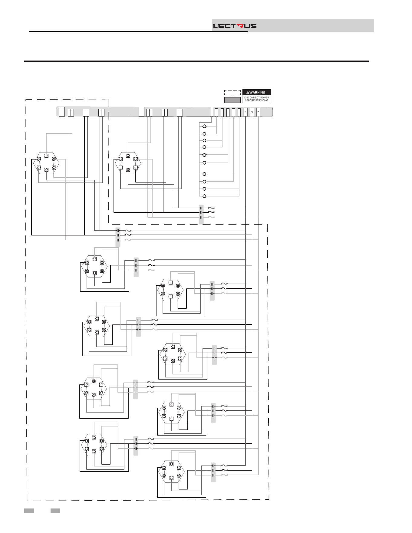
Figure 8-2 Wiring Diagram - 208V, 3 Phase (B)
8 Diagrams (continued)
Installation & Operation Manual
TM
Notes:
1. All wiring must be installed in
accordance with local, state,
provincial and national code
requirements per either N.E.C in
USA or C.S.A in Canada.
2. If any original equipment wire
was supplied with the appliance
must be replaced, it must be
replaced with wire having the
same wire gauge (AWG) and
rated for a minimum of 105°C.
Exceptions: Any wiring listed on
the replacement parts list and
ribbon cable must be purchased
from the factory. Use of a non-
approved factory replacement
harness lead or ribbon cable
can lead to operational
problems which could result in
non-repairable damage to the
integrated controller or other
components.
3. Actual connector block locations
may vary from those shown
on diagrams. Refer to actual
components for proper connector
block locations when using
diagrams to trouble shoot the
unit.
J6-1
J5-1
J6-1
J5-1
J2-1
J1-1
J2-1
J1-1
J4-1
J3-1
J4-1
J3-1
TRIAC 2
TRIAC 1
J6-1
J5-1
J6-1
J5-1
J2-1
J1-1
J2-1
J1
-
J4-1
J3-1
J4-1
J3-1
14
8
6
10
12
K2
K6
K8
K10
K4
120Neu
K1
K4
K2
K7
K5
K1
K3
K9
1 2 3
1 2 3
1 2 3
1 2 3
1 2 3
1 2 3
1 2 3
1 2 3
1 2 3
1 2 3
1 2 3
1 2 3
K3
1 2 3
1 2 3
1 2 3
1 2 3
K6
1 2 3
1 2 3
1 2 3
1 2 3
K5
1 2 3
1 2 3
1 2 3
1 2 3
K8
1 2 3
1 2 3
1 2 3
1 2 3
K7
1 2 3
1 2 3
1 2 3
1 2 3
K10
1 2 3
1 2 3
1 2 3
1 2 3
K9
1 2 3
1 2 3
1 2 3
1 2 3
YTICAPAC GNITAEH WK TINU NO TNEDNEPED SI STNEMELE & SROTCATNOC FO REBMUN LAUTCA :ETON
.
.
.
.
.
.
.
.
.
.
.
.
.
.
.
.
.
.
.
.
.
.
.
.
.
.
.
.
.
.
.
.
.
.
.
.
.
.
.
.
.
.
.
.
.
.
.
BOX DEPICTS
OPTIONAL ITEMS
BOX DEPICTS
DUAL SENSOR
SINGLE HOUSING
100373648 REV D
K2B BLU
K2A BLU
K2A BLK
K2B BLK
K2A RED
K2B RED
K1B BLU
K1A BLU
K1A BLK
K1B BLK
K1A RED
K1B RED
K2 BLK
K2B RED
K2B BLU
K2B BLK
K2 BLU
K2 RED
K1 BLK
K1B RED
K1B BLU
K1B BLK
K1 BLU
K1 RED
K1 RED
K1 BLK
K1 BLU
K2 RED
K2 BLK
K2 BLU
K4 BLK
K4 RED
K4 BLU
K4 BLK
K4 BLU
K4 RED
K4 RED
K4 BLK
K4 BLU
K3 BLK
K3 RED
K3 BLU
K3 BLK
K3 RED
K3 BLU
K3 RED
K3 BLK
K3 BLU
.
.
.
K6 BLK
K6 RED
K6 BLU
K6 BLK
K6 BLU
K6 RED
K6 RED
K6 BLK
K6 BLU
K5 BLK
K5 RED
K5 BLU
K5 BLK
K5 BLU
K5 RED
K5 RED
K5 BLK
K5 BLU
K8 BLK
K8 RED
K8 BLU
K8 BLK
K8 BLU
K8 RED
K8 RED
K8 BLK
K8 BLU
K10 BLK
K10 RED
K10 BLU
K10 BLK
K10 BLU
K10 RED
K10 RED
K10 BLK
K10 BLU
K7 BLK
K7 RED
K7 BLU
K7 BLK
K7 BLU
K7 RED
.
.
.
.
K7 RED
K7 BLK
K7 BLU
K9 BLK
K9 RED
K9 BLU
K9 BLK
K9 BLU
K9 RED
K9 RED
K9 BLK
K9 BLU
.
.
.
.
.
.
.
.
.
.
.
.
.
.
.
.
.
60
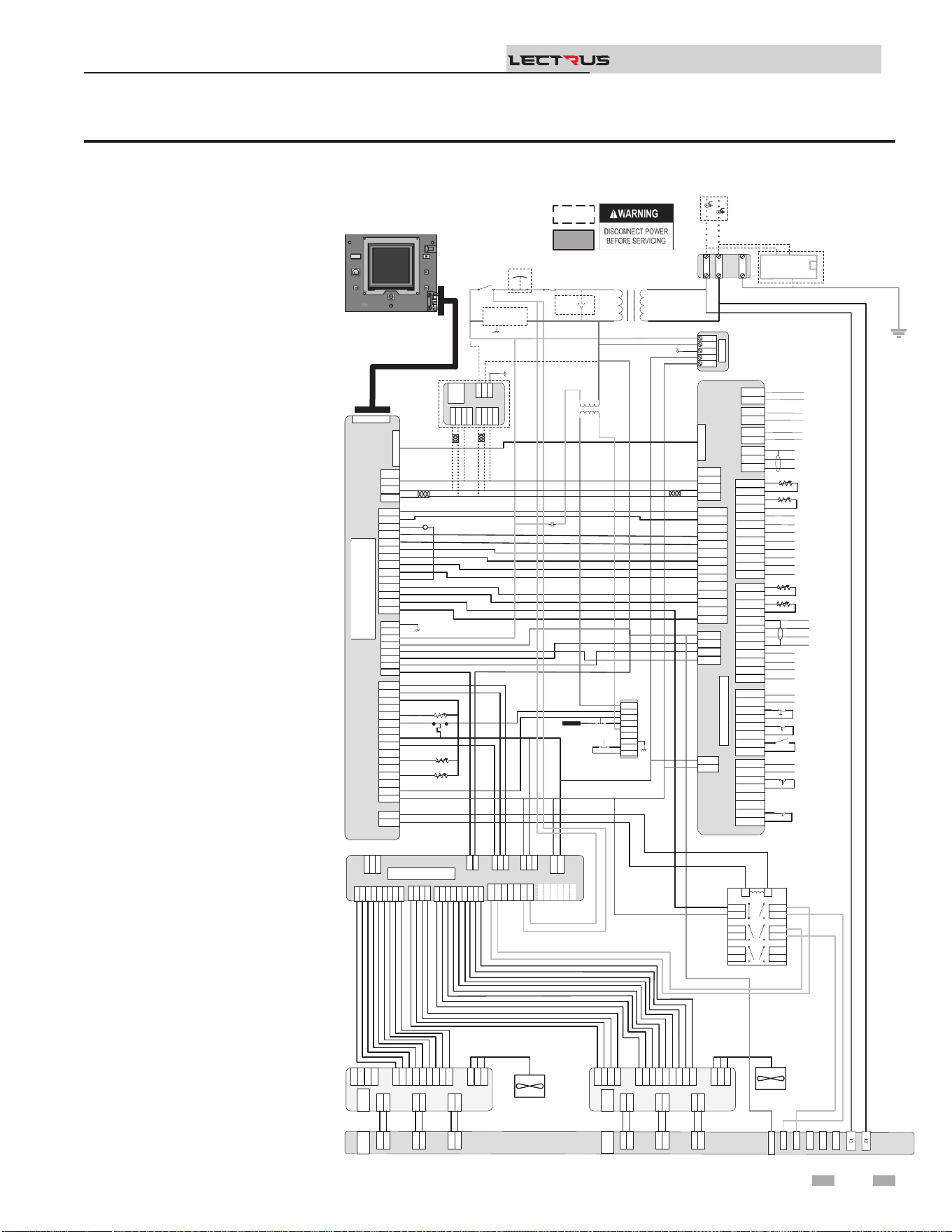
Figure 8-3 Wiring Diagram - 240V 1 Phase (A)
8 Diagrams
Installation & Operation Manual
TM
Notes:
1. All wiring must be installed in
accordance with local, state,
provincial and national code
requirements per either N.E.C in
USA or C.S.A in Canada.
2. If any original equipment wire
was supplied with the appliance
must be replaced, it must be
replaced with wire having the
same wire gauge (AWG) and
rated for a minimum of 105°C.
Exceptions: Any wiring listed on
the replacement parts list and
ribbon cable must be purchased
from the factory. Use of a non-
approved factory replacement
harness lead or ribbon cable
can lead to operational
problems which could result in
non-repairable damage to the
integrated controller or other
components.
3. Actual connector block locations
may vary from those shown
on diagrams. Refer to actual
components for proper connector
block locations when using
diagrams to trouble shoot the
unit.
+V
-V
GND
N
L
+V
-V
GND
N
L
PSU
+V
-V
GND
N
L
24VDC PSU
J2-1
J2-2
J2-3
J3-1
J3-2
J3-3
J3-4
J3-5
J3-6
X7-RIBBON
X4-1
X4-2
X4-3
X4-4
X4-5
X4-6
X4-7
X4-8
X4-9
X4-10
X4-11
X4-12
X4-13
X4-14
X4-1
X4-2
X4-3
X4-4
X4-5
X4-6
X4-7
X4-8
X4-9
X4-10
X4-11
X4-12
X4-13
X4-14
X9-1
X9-2
X9-3
X9-4
X9-1
X9-2
X9-3
X9-4
X5-1
X5-2
X5-3
X5-4
X5-5
X5-6
X5-7
X5-8
X5-9
X5-10
X5-11
X5-12
X5-13
X5-14
X5-15
X5-16
X5-1
X5-2
X5-3
X5-4
X5-5
X5-6
X5-7
X5-8
X5-9
X5-10
X5-11
X5-12
X5-13
X5-14
X5-15
X5-16
X1-1
X1-2
X1-3
X1-4
X1-5
X1-6
X1-7
X1-8
X1-1
X1-2
X1-3
X1-4
X1-5
X1-6
X1-7
X1-8
X2-1
X2-2
X2-1
X2-2
BIC
X6 RIBBON
X7-RIBBON
X4-1
X4-2
X4-3
X4-4
X4-5
X4-6
X4-7
X4-8
X4-9
X4-10
X4-11
X4-12
X4-13
X4-14
X9-1
X9-2
X9-3
X9-4
X5-1
X5-2
X5-3
X5-4
X5-5
X5-6
X5-7
X5-8
X5-9
X5-10
X5-11
X5-12
X5-13
X5-14
X5-15
X5-16
X1-1
X1-2
X1-3
X1-4
X1-5
X1-6
X1-7
X1-8
X2-1
X2-2
X6 RIBBON
CN5-1
CN5-2
CN5-3
CN5-1
CN5-2
CN5-3
DHW1
DHW2
DHW1
DHW2
SYS1
SYS2
SYS1
SYS2
BLR1
BLR2
BLR1
BLR2
CN3-1-1
CN3-1-2
CN3-1-3
CN3-1-4
CN3-1-5
CN3-1-6
CN3-1-7
CN3-1-8
CN3-1-1
CN3-1-2
CN3-1-3
CN3-1-4
CN3-1-5
CN3-1-6
CN3-1-7
CN3-1-8
CN3-2-1
CN3-2-2
CN3-2-3
CN3-2-4
CN3-2-5
CN3-2-6
CN3-2-7
CN3-2-8
CN3-2-1
CN3-2-2
CN3-2-3
CN3-2-4
CN3-2-5
CN3-2-6
CN3-2-7
CN3-2-8
J1-1
J1-2
J1-3
J1-4
J1-1
J1-2
J1-3
J1-4
CN9-1
CN9-2
CN9-3
CN9-4
CN9-1
CN9-2
CN9-3
CN9-4
CN4-1
CN4-2
CN4-3
CN4-4
CN4-5
CN4-6
CN4-7
CN4-8
CN4-9
CN4-10
CN4-11
CN4-12
CN4-13
CN4-14
CN4-1
CN4-2
CN4-3
CN4-4
CN4-5
CN4-6
CN4-7
CN4-8
CN4-9
CN4-10
CN4-11
CN4-12
CN4-13
CN4-14
Connecon Board
CN6 RIBBON
DHW Pump (120VAC 0.75A Max)
System Pump (120VAC 0.75A Max)
Boiler Pump (120VAC 0.75 Max)
Shield
A
B
Run Time Contacts
Low Pressure Switch
Flow Switch
Demand Enable
Alarm Contacts
DHW Demand
External LWCO
GNDGND
L2L2
L1L1
Fuse
Main Voltage120 VAC
120V
24VAC
LWCO
Test
Reset
Probe
Power
On/Off
J6-1
J5-1
J6-1
J5-1
J2-1
J1-1
J2-1
J1-1
J4-1
J3-1
J4-1
J3-1
TRIAC 2
TRIAC 1
J6-1
J5-1
J6-1
J5-1
J2-1
J1-1
J2-1
J1-1
J4-1
J3-1
J4-1
J3-1
J8-9
J8-8
J8-7
J8-6
J8-5
J8-4
J8-3
J8-2
J8-1
J8-9
J8-8
J8-7
J8-6
J8-5
J8-4
J8-3
J8-2
J8-1
J7
-
4
J7-3
J7-2
J7-1
J7
-
4
J7-3
J7-2
J7-1
J9-1
J9-2
J9-3
J9-1
J9-2
J9-3
J6-1
J5-1
J6-1
J5-1
J2-1
J1-1
J2-1
J1-1
J4-1
J3-1
J4-1
J3-1
J8-9
J8-8
J8-7
J8-6
J8-5
J8-4
J8-3
J8-2
J8-1
J7
-
4
J7-3
J7-2
J7-1
J9-1
J9-2
J9-3
J6-1
J5-1
J2-1
J1-1
J4-1
J3-1
TRIAC 1
J8-9
J8-8
J8-7
J8-6
J8-
5
J8-4
J8-3
J8-2
J8-1
J8-9
J8-8
J8-7
J8-6
J8-
5
J8-4
J8-3
J8-2
J8-1
J7-4
J7-3
J7-2
J7-1
J7-4
J7-3
J7-2
J7-1
J9-1
J9
-
2
J9-3
J9-1
J9
-
2
J9-3
J6
-1
J5-1
J6
-1
J5-1
J2-1
J1-1
J2-1
J1-1
J4-1
J3-1
J4-1
J3-1
TRIAC 2
J8-9
J8-8
J8-7
J8-6
J8-
5
J8-4
J8-3
J8-2
J8-1
J7-4
J7-3
J7-2
J7-1
J9-1
J9
-
2
J9-3
J6
-1
J5-1
J2-1
J1-1
J4-1
J3-1
TRIAC 2
14
8
6
10
12
120Neu
R6
R6 LWCO RELAY
3
4
7
8
11
12
5
6
9
10
13
14
1
2
3
4
7
8
11
12
5
6
9
10
13
14
1
2
LR
3
4
7
8
11
12
5
6
9
10
13
14
1
2
LR
RED
BLK
Safety
Interlock
240 VAC 1 ɸ
Oponal Current Transformers
For Power Meter
GND
J3-1
J3-2
J3-3
J3-4
J3-5
J3-6
J3
-
7
J3-8
J3-9
J3-1
J3-2
J3-3
J3-4
J3-5
J3-6
J3
-
7
J3-8
J3-9
J2-1
J2-2
J2-3
J2-4
J2-5
J2-6
J2-7
J2-8
J2-9
J2-1
J2-2
J2-3
J2-4
J2-5
J2-6
J2-7
J2-8
J2-9
J9-1
J9-2
J9-3
J9-4
J9-1
J9-2
J9-3
J9-4
J27-1
J27-2
J27-1
J27-2
J1-1
J1-2
J1-
3
J1-1
J1-2
J1-
3
J8-1
J8-2
J8-3
J8-4
J8-5
J8-1
J8-2
J8-3
J8-4
J8-5
J16-1
J16-2
J16-3
J15-1
J15-2
J12-1
J12-2
J16-1
J16-2
J16-3
J15-1
J15-2
J12-1
J12-2
J10-1
J10-2
J10-3
J10-4
J10-5
J10-6
J10-1
J10-2
J10-3
J10-4
J10-5
J10-6
MCB
J3-1
J3-2
J3-3
J3-4
J3-5
J3-6
J3
-
7
J3-8
J3-9
J2-1
J2-2
J2-3
J2-4
J2-5
J2-6
J2-7
J2-8
J2-9
J9-1
J9-2
J9-3
J9-4
J27-1
J27-2
J1-1
J1-2
J1-
3
J8-1
J8-2
J8-3
J8-4
J8-5
J16-1
J16-2
J16-3
J15-1
J15-2
J12-1
J12-2
J10-1
J10-2
J10-3
J10-4
J10-5
J10-6
MCB
J22-1
J22-2
J22-3
J22-1
J22-2
J22-3
J3-1
J3-2
J3-3
J3-4
J3-5
J3-6
J3
-
7
J3-8
J3-9
J2-1
J2-2
J2-3
J2-4
J2-5
J2-6
J2-7
J2-8
J2-9
J9-1
J9-2
J9-3
J9-4
J27-1
J27-2
J1-1
J1-2
J1-
3
J8-1
J8-2
J8-3
J16-1
J16-2
J16-3
J15-1
J15-2
J12-1
J12-2
J10-1
J10-2
J10-3
J10-4
J10-5
J10-6
MODULATION CONTROL BOARD
(MCB)
J22-1
J22-2
J22-3
X4-1
X4
-
2
X4-3
X4-4
X4-1
X4
-
2
X4-3
X4-4
RS-485RS-485
J1-1
J1
-
2
J1-3
J1-1
J1
-
2
J1-3
X6-1
X6-2
X6-3
X6-4
X6-1
X6-2
X6-3
X6-4
Modbus/BacNet
X4-1
X4
-
2
X4-3
X4-4
RS-485
J1-1
J1
-
2
J1-3
X6-1
X6-2
X6-3
X6-4
Modbus/BacNet
A
B
GND
A
B
A
B
A
B
CN1-1
CN1-2
CN1-3
CN1-4
CN1-5
CN1-6
CN1-7
CN1-8
CN1-9
CN1-10
CN1-11
CN1-12
CN1-1
CN1-2
CN1-3
CN1-4
CN1-5
CN1-6
CN1-7
CN1-8
CN1-9
CN1-10
CN1-11
CN1-12
Outdoor Sensor
Tank Sensor
System Sensor
DHW Recirc Sensor
CN2-1
CN2-2
CN2-3
CN2-4
CN2-5
CN2-6
CN2-7
CN2-8
CN2-9
CN2-10
CN2-11
CN2-12
CN2-1
CN2-2
CN2-3
CN2-4
CN2-5
CN2-6
CN2-7
CN2-8
CN2-9
CN2-10
CN2-11
CN2-12
-
+ Alarm Power
-
+ Alarm Power
-
+ 0-10V Rate Out
-
+ 0-10V Rate Out
-
+ 0-10V System Out
-
+ 0-10V System Out
-
+ 0-10V BMS In
-
+ 0-10V BMS In
Shield
Shield
Cascade
-
+ 0-10V System Pump In
-
+ 0-10V System Pump In
-
+ CT Power
-
+ CT Power
CN1-1
CN1-2
CN1-3
CN1-4
CN1-5
CN1-6
CN1-7
CN1-8
CN1-9
CN1-10
CN1-11
CN1-12
Outdoor Sensor
Tank Sensor
System Sensor
DHW Recirc Sensor
CN2-12
CN2-11
CN2-10
CN2-9
CN2-8
CN2-7
CN2-6
CN2-5
CN2-4
CN2-3
CN2-2
CN2-1
-
+ Alarm Power
-
+ 0-10V Rate Out
-
+ 0-10V System Out
-
+ 0-10V BMS In
Shield
Shield
Cascade
-
+ 0-10V System Pump In
-
+ CT Power
.
.
.
.
.
.
.
.
.
.
...
100374963 REV E
BOX DEPICTS
OPTIONAL ITEMS
BOX DEPICTS
DUAL SENSOR
SINGLE HOUSING
MRHL
J17-2
J17-1
J2
-1
J2-2
.
.
.
.
E-Stop
.
.
BLK/WHT
BLU
YEL
BLK/WHT
WHT
GRN
BLK
RED
ORNG
RED
BLK
YEL
.
BLK/WHT
YEL
YEL
YEL
ORNG
RED
RED
ORNG
YEL/WHT
BL
PRPL
GRY
PNK
PNK
GRY
PRPL/WHT
BL
YEL
RED
ORNG
BLK/YEL
BRWN
BLK
RED/BLK
BLK/WHT
WHT
BLK/WHT
BLK/WHT
BLK/WHT
BLK/WHT
Outlet
BLU
ORNG
BLK
BLK
Inlet
GRY
Outlet
BLU
WHT/ORNG
RED
RED/BLK
BLK
BLU/YEL
ORNG
WHT/ORNG
BLK/ORNG
GND
BLK/WHT
WHT
RED
BLK
RED
BLK
BLK/WHT
BLK/WHT
9/2
5/1
GRN
BRN
PNK
GRY
PRPL
BLU
YEL
ORNG
RED
BLU/BLK
YEL/BLK
RED/BLK
ORNG/BLK
GRN
BRN
PNK
GRY
PRPL
BLU
YEL
ORNG
RED
RED
BLK
YEL
RED
RED
BLK
BLK
BLU
BLU
RED
RED
BLK
BLK
BLU
BLU
BLK
RED
RED
BLK
.
DISPLAY
BOILER INTERGRATED CONTROL
(BIC)
Safety
Monitor
Relay
TRIAC Fan
TRIAC Fan
16
17
Relay
Output
7
8
19
Ground Fault
Protector
POWER
METER
L
N
GND
.
.
.
.
.
.
.
.
.
GND
GND
61
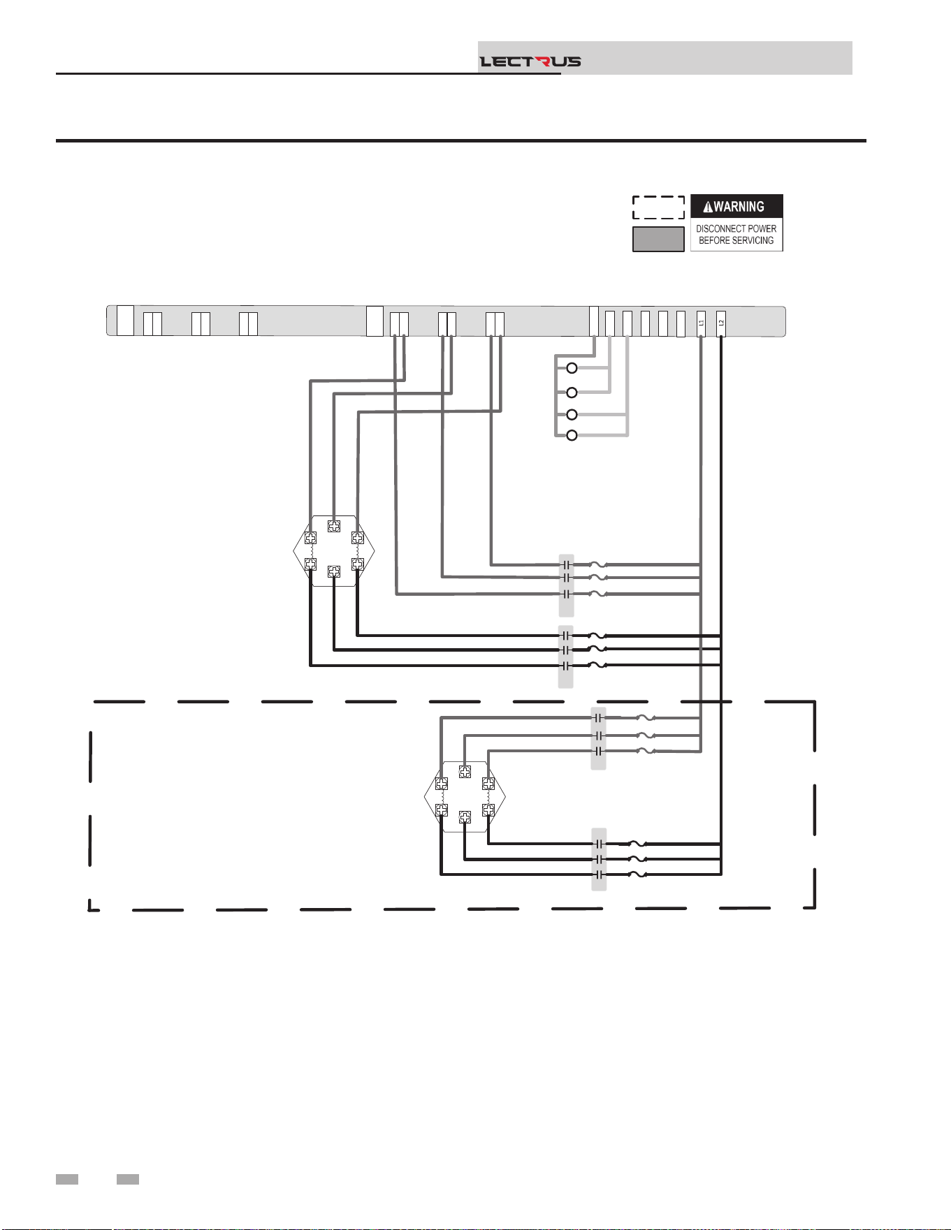
Figure 8-4 Wiring Diagram - 240V 1 Phase (B)
8 Diagrams
Installation & Operation Manual
TM
Notes:
1. All wiring must be installed in accordance with local, state, provincial and national code requirements per either
N.E.C in USA or C.S.A in Canada.
2. If any original equipment wire was supplied with the appliance must be replaced, it must be replaced with wire having
the same wire gauge (AWG) and rated for a minimum of 105°C. Exceptions: Any wiring listed on the replacement
parts list and ribbon cable must be purchased from the factory. Use of a non-approved factory replacement harness
lead or ribbon cable can lead to operational problems which could result in non-repairable damage to the integrated
controller or other components.
3. Actual connector block locations may vary from those shown on diagrams. Refer to actual components for proper
connector block locations when using diagrams to trouble shoot the unit.
J6-1
J5-1
J6-1
J5-1
J2-1
J1-1
J2-1
J1-1
J4-1
J3-1
J4-1
J3-1
TRIAC 2
TRIAC 1
J6-1
J5-1
J6-1
J5-1
J2-1
J1-1
J2-1
J1-1
J4-1
J3-1
J4-1
J3-1
14
8
6
10
12
K2
K4
120Neu
K1
K3
K2
K1
K3
1 2 3
1 2 3
1 2 3
1 2 3
1 2 3
1 2 3
1 2 3
1 2 3
K4
NOTE: ACTUAL NUMBER OF CONTACTORS & ELEMENTS IS DEPENDENT ON UNIT KW HEATING CAPACITY
.
.
.
.
.
.
.
.
.
.
.
BOX DEPICTS
OPTIONAL ITEMS
BOX DEPICTS
DUAL SENSOR
SINGLE HOUSING
100375252 REV C
K1A RED
K1B RED
K1C RED
K1D RED
K1E RED
K1F RED
RED
BLK
K1B RED
K1D RED
K1F RED
K2 BLK
K2 BLK
K2 BLK
K1E RED
K1C RED
K1A RED
K2 BLK
K2 BLK
K2 BLK
K3 RED
K3 RED
K3 RED
K4 BLK
K4 BLK
K4 BLK
K3 RED
K3 RED
K3 RED
K4 BLK
K4 BLK
K4 BLK
.
.
.
.
62
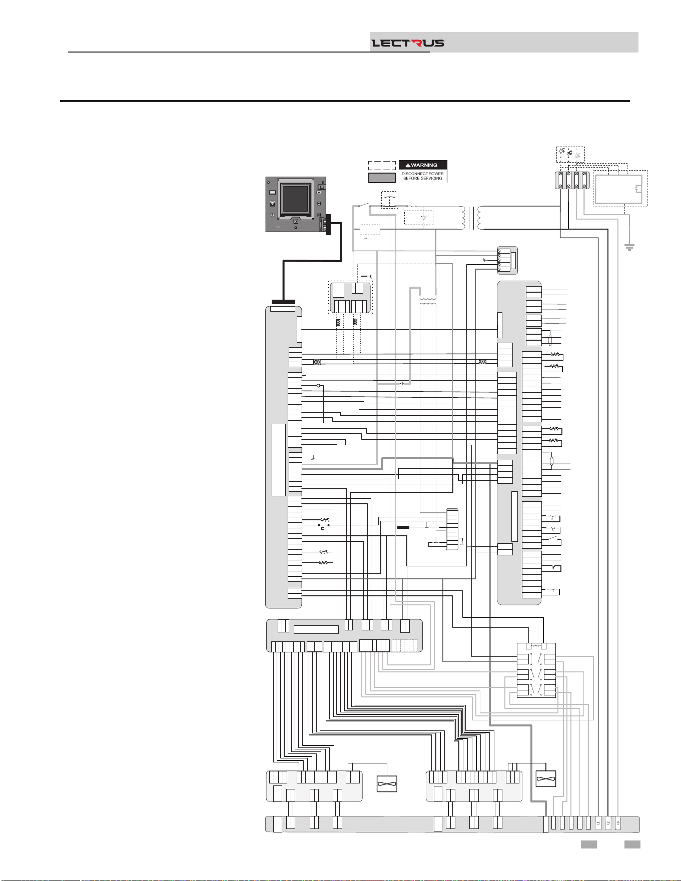
Figure 8-5 Wiring Diagram - 400-600V, 3 Phase (A)
8 Diagrams (continued)
Installation & Operation Manual
TM
Notes:
1. All wiring must be installed in
accordance with local, state,
provincial and national code
requirements per either N.E.C in
USA or C.S.A in Canada.
2. If any original equipment wire
was supplied with the appliance
must be replaced, it must be
replaced with wire having the
same wire gauge (AWG) and
rated for a minimum of 105°C.
Exceptions: Any wiring listed on
the replacement parts list and
ribbon cable must be purchased
from the factory. Use of a non-
approved factory replacement
harness lead or ribbon cable
can lead to operational
problems which could result in
non-repairable damage to the
integrated controller or other
components.
3. Actual connector block locations
may vary from those shown
on diagrams. Refer to actual
components for proper connector
block locations when using
diagrams to trouble shoot the
unit.
+V
-V
GND
N
L
+V
-V
GND
N
L
PSU
+V
-V
GND
N
L
24VDC PSU
J2-1
J2-2
J2-3
J3-1
J3-2
J3-3
J3-4
J3-5
J3-6
X7-RIBBON
X4-1
X4-2
X4-3
X4-4
X4-5
X4-6
X4-7
X4-8
X4-9
X4-10
X4-11
X4-12
X4-13
X4-14
X4-1
X4-2
X4-3
X4-4
X4-5
X4-6
X4-7
X4-8
X4-9
X4-10
X4-11
X4-12
X4-13
X4-14
X9-1
X9-2
X9-3
X9-4
X9-1
X9-2
X9-3
X9-4
X5-1
X5-2
X5-3
X5-4
X5-5
X5-6
X5-7
X5-8
X5-9
X5-10
X5-11
X5-12
X5-13
X5-14
X5-15
X5-16
X5-1
X5-2
X5-3
X5-4
X5-5
X5-6
X5-7
X5-8
X5-9
X5-10
X5-11
X5-12
X5-13
X5-14
X5-15
X5-16
X1-1
X1-2
X1-3
X1-4
X1-5
X1-6
X1-7
X1-8
X1-1
X1-2
X1-3
X1-4
X1-5
X1-6
X1-7
X1-8
X2-1
X2-2
X2-1
X2-2
BIC
X6 RIBBON
X7-RIBBON
X4-1
X4-2
X4-3
X4-4
X4-5
X4-6
X4-7
X4-8
X4-9
X4-10
X4-11
X4-12
X4-13
X4-14
X9-1
X9-2
X9-3
X9-4
X5-1
X5-2
X5-3
X5-4
X5-5
X5-6
X5-7
X5-8
X5-9
X5-10
X5-11
X5-12
X5-13
X5-14
X5-15
X5-16
X1-1
X1-2
X1-3
X1-4
X1-5
X1-6
X1-7
X1-8
X2-1
X2-2
X6 RIBBON
CN5-1
CN5-2
CN5-3
CN5-1
CN5-2
CN5-3
DHW1
DHW2
DHW1
DHW2
SYS1
SYS2
SYS1
SYS2
BLR1
BLR2
BLR1
BLR2
CN3-1-1
CN3-1-2
CN3-1-3
CN3-1-4
CN3-1-5
CN3-1-6
CN3-1-7
CN3-1-8
CN3-1-1
CN3-1-2
CN3-1-3
CN3-1-4
CN3-1-5
CN3-1-6
CN3-1-7
CN3-1-8
CN3-2-1
CN3-2-2
CN3-2-3
CN3-2-4
CN3-2-5
CN3-2-6
CN3-2-7
CN3-2-8
CN3-2-1
CN3-2-2
CN3-2-3
CN3-2-4
CN3-2-5
CN3-2-6
CN3-2-7
CN3-2-8
J1-1
J1-2
J1-3
J1-4
J1-1
J1-2
J1-3
J1-4
CN9-1
CN9-2
CN9-3
CN9-4
CN9-1
CN9-2
CN9-3
CN9-4
CN4-1
CN4-2
CN4-3
CN4-4
CN4-5
CN4-6
CN4-7
CN4-8
CN4-9
CN4-10
CN4-11
CN4-12
CN4-13
CN4-14
CN4-1
CN4-2
CN4-3
CN4-4
CN4-5
CN4-6
CN4-7
CN4-8
CN4-9
CN4-10
CN4-11
CN4-12
CN4-13
CN4-14
Connecon Board
CN6 RIBBON
DHW Pump (120VAC 0.75 Max)
System Pump (120VAC 0.75 Max)
Boiler Pump (120VAC 0.75 Max)
Shield
A
B
Run Time Contacts
Low Pressure Switch
Flow Switch
Demand Enable
Alarm Contacts
DHW Demand
External LWCO
120V
24VAC
LWCO
Test
Reset
Probe
J6-1
J5-1
J6-1
J5-1
J2-1
J1-1
J2-1
J1-1
J4-1
J3-1
J4-1
J3-1
TRIAC 2
TRIAC 1
J6-1
J5-1
J6-1
J5-1
J2-1
J1-1
J2-1
J1-1
J4-1
J3-1
J4-1
J3-1
J8-9
J8-8
J8-7
J8-6
J8-5
J8-4
J8-3
J8-2
J8-1
J8-9
J8-8
J8-7
J8-6
J8-5
J8-4
J8-3
J8-2
J8-1
J7-4
J7-3
J7-2
J7-1
J7-4
J7-3
J7-2
J7-1
J9-1
J9-2
J9-3
J9-1
J9-2
J9-3
J6-1
J5-1
J6-1
J5-1
J2-1
J1-1
J2-1
J1-1
J4-1
J3-1
J4-1
J3-1
J8-9
J8-8
J8-7
J8-6
J8-5
J8-4
J8-3
J8-2
J8-1
J7-4
J7-3
J7-2
J7-1
J9-1
J9-2
J9-3
J6-1
J5-1
J2-1
J1-1
J4-1
J3-1
TRIAC 1
J8-9
J8-8
J8-7
J8-6
J8-5
J8-4
J8-3
J8-2
J8-1
J8-9
J8-8
J8-7
J8-6
J8-5
J8-4
J8-3
J8-2
J8-1
J7-4
J7-3
J7-2
J7-1
J7-4
J7-3
J7-2
J7-1
J9-1
J9-2
J9-3
J9-1
J9-2
J9-3
J6-1
J5-1
J6-1
J5-1
J2-1
J1-1
J2-1
J1-1
J4-1
J3-1
J4-1
J3-1
TRIAC 2
J8-9
J8-8
J8-7
J8-6
J8-5
J8-4
J8-3
J8-2
J8-1
J7-4
J7-3
J7-2
J7-1
J9-1
J9-2
J9-3
J6-1
J5-1
J2-1
J1-1
J4-1
J3-1
TRIAC 2
14
8
6
10
12
120Neu
R6
R6
3
4
7
8
11
12
5
6
9
10
13
14
1
2
3
4
7
8
11
12
5
6
9
10
13
14
1
2
LR
3
4
7
8
11
12
5
6
9
10
13
14
1
2
LR
GND
J3-1
J3-2
J3-3
J3-4
J3-5
J3-6
J3-7
J3-8
J3-9
J3-1
J3-2
J3-3
J3-4
J3-5
J3-6
J3-7
J3-8
J3-9
J2-1
J2-2
J2-3
J2-4
J2-5
J2-6
J2-7
J2-8
J2-9
J2-1
J2-2
J2-3
J2-4
J2-5
J2-6
J2-7
J2-8
J2-9
J9-1
J9-2
J9-3
J9-4
J9-1
J9-2
J9-3
J9-4
J27-1
J27-2
J27-1
J27-2
J1-1
J1-2
J1-3
J1-1
J1-2
J1-3
J8-1
J8-2
J8-3
J8-4
J8-5
J8-1
J8-2
J8-3
J8-4
J8-5
J16-1
J16-2
J16-3
J15-1
J15-2
J12-1
J12-2
J16-1
J16-2
J16-3
J15-1
J15-2
J12-1
J12-2
J10-1
J10-2
J10-3
J10-4
J10-5
J10-6
J10-1
J10-2
J10-3
J10-4
J10-5
J10-6
MCB
J3-1
J3-2
J3-3
J3-4
J3-5
J3-6
J3-7
J3-8
J3-9
J2-1
J2-2
J2-3
J2-4
J2-5
J2-6
J2-7
J2-8
J2-9
J9-1
J9-2
J9-3
J9-4
J27-1
J27-2
J1-1
J1-2
J1-3
J8-1
J8-2
J8-3
J8-4
J8-5
J16-1
J16-2
J16-3
J15-1
J15-2
J12-1
J12-2
J10-1
J10-2
J10-3
J10-4
J10-5
J10-6
MCB
J22-1
J22-2
J22-3
J22-1
J22-2
J22-3
MODULATED CONTROL BOARD
(MCB)
X4-1
X4-2
X4-3
X4-4
X4-1
X4-2
X4-3
X4-4
RS-485RS-485
J1-1
J1-2
J1-3
J1-1
J1-2
J1-3
X6-1
X6-2
X6-3
X6-4
X6-1
X6-2
X6-3
X6-4
Modbus/BacNet
X4-1
X4-2
X4-3
X4-4
RS-485
J1-1
J1-2
J1-3
X6-1
X6-2
X6-3
X6-4
Modbus/BacNet
A
B
GND
A
B
A
B
A
B
CN1-1
CN1-2
CN1-3
CN1-4
CN1-5
CN1-6
CN1-7
CN1-8
CN1-9
CN1-10
CN1-11
CN1-12
CN1-1
CN1-2
CN1-3
CN1-4
CN1-5
CN1-6
CN1-7
CN1-8
CN1-9
CN1-10
CN1-11
CN1-12
Outdoor Sensor
Tank Sensor
System Sensor
DHW Recirc Sensor
CN2-1
CN2-2
CN2-3
CN2-4
CN2-5
CN2-6
CN2-7
CN2-8
CN2-9
CN2-10
CN2-11
CN2-12
CN2-1
CN2-2
CN2-3
CN2-4
CN2-5
CN2-6
CN2-7
CN2-8
CN2-9
CN2-10
CN2-11
CN2-12
-
+ Alarm Power
-
+ Alarm Power
-
+ 0-10V Rate Out
-
+ 0-10V Rate Out
-
+ 0-10V System Out
-
+ 0-10V System Out
-
+ 0-10V BMS In
-
+ 0-10V BMS In
Shield
Shield
Cascade
-
+ 0-10V System Pump In
-
+ 0-10V System Pump In
-
+ CT Power
-
+ CT Power
CN1-1
CN1-2
CN1-3
CN1-4
CN1-5
CN1-6
CN1-7
CN1-8
CN1-9
CN1-10
CN1-11
CN1-12
Outdoor Sensor
Tank Sensor
System Sensor
DHW Recirc Sensor
CN2-12
CN2-11
CN2-10
CN2-9
CN2-8
CN2-7
CN2-6
CN2-5
CN2-4
CN2-3
CN2-2
CN2-1
-
+ Alarm Power
-
+ 0-10V Rate Out
-
+ 0-10V System Out
-
+ 0-10V BMS In
Shield
Shield
Cascade
-
+ 0-10V System Pump In
-
+ CT Power
.
.
.
.
.
.
.
.
BOX DEPICTS
OPTIONAL ITEMS
BOX DEPICTS
DUAL SENSOR
SINGLE HOUSING
100375002 REV E
MRHL
J3-1
J3-2
J3-3
J3-4
J3-5
J3-6
J3-7
J3-8
J3-9
J2-1
J2-2
J2-3
J2-4
J2-5
J2-6
J2-7
J2-8
J2-9
J9-1
J9-2
J9-3
J9-4
J27-1
J27-2
J1-1
J1-2
J1-3
J8-1
J8-2
J8-3
J16-1
J16-2
J16-3
J15-1
J15-2
J12-1
J12-2
J10-1
J10-2
J10-3
J10-4
J10-5
J10-6
J22-1
J22-2
J22-3
J17-2
J17-1
J2
-1
J2-2
.
.
Fuse
Main Voltage120 VAC
Power
On/Off
Safety
Interlock
.
E-Stop
.
.
BLK/WHT
BLU
YEL
GNDGND
L3L3
L2L2
L1L1
GND
L3
L2
L1
RED BLK BLU
480/600VAC 3
ɸ
Oponal Current Transformers
For Power Meter
.
BLU
BLK/WHT
YEL
YEL
YEL
ORNG
RED
RED
ORNG
YEL/WHT
BL
PRPL
GRY
PNK
PNK
GRY
PRPL/WHT
BL
YEL
RED
ORNG
BLK/YEL
BRWN
BLK
RED/BLK
BLK/WHT
WHT
BLK/WHT
BLK/WHT
BLK/WHT
BLK/WHT
Outlet
BLU
ORNG
BLK
BLK
Inlet
GRY
Outlet
BLU
WHT/ORNG
RED
RED/BLK
BLK
BLU/YEL
ORNG
WHT/ORNG
BLK/ORNG
GND
BLK/WHT
WHT
RED
BLK
RED
BLK
BLK/WHT
BLK/WHT
9/2
5/1
GRN
BRN
PNK
GRY
PRPL
BLU
YEL
ORNG
RED
BLU/BLK
YEL/BLK
RED/BLK
ORNG/BLK
GRN
BRN
PNK
GRY
PRPL
BLU
YEL
ORNG
RED
RED
BLK
YEL
RED
RED
BLK
BLK
BLU
BLU
RED
RED
BLK
BLK
BLU
BLU
BLK
RED
13/3
11/4
7/5
ORNG
BLK
ORNG (480 V) / BRN (600 V)
BLK/WHT
.
.
WHT
GRN
BLK
RED
RED
YEL
BLK
.
.
.
.
.
.
.
BOILER INTERGRATED CONTROL
(BIC)
.
.
.
.
.
.
POWER
METER
L
N
GND
.
16
17
Relay
Output
1
3
5
19
Ground Fault
Protector
Safety
Monitor
Relay
TRIAC Fan
TRIAC Fan
DISPLAY
63
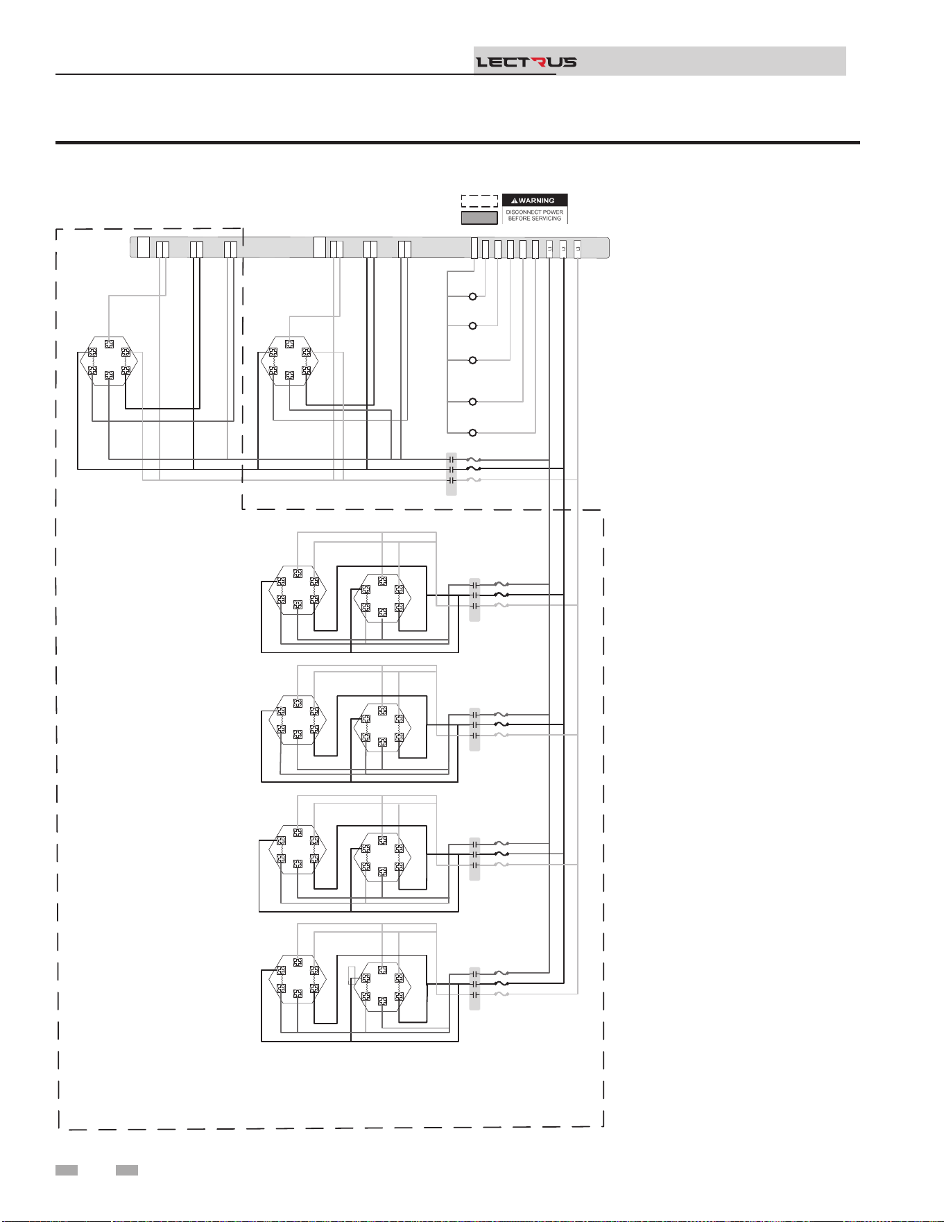
Figure 8-6 Wiring Diagram - 400-600V, 3 Phase (B)
8 Diagrams
Installation & Operation Manual
TM
Notes:
1. All wiring must be installed in
accordance with local, state,
provincial and national code
requirements per either N.E.C in
USA or C.S.A in Canada.
2. If any original equipment wire
was supplied with the appliance
must be replaced, it must be
replaced with wire having the
same wire gauge (AWG) and
rated for a minimum of 105°C.
Exceptions: Any wiring listed on
the replacement parts list and
ribbon cable must be purchased
from the factory. Use of a non-
approved factory replacement
harness lead or ribbon cable
can lead to operational
problems which could result in
non-repairable damage to the
integrated controller or other
components.
3. Actual connector block locations
may vary from those shown
on diagrams. Refer to actual
components for proper connector
block locations when using
diagrams to trouble shoot the
unit.
J6-1
J5-1
J6-1
J5-1
J2-1
J1-1
J2-1
J1-1
J4-1
J3-1
J4-1
J3-1
TRIAC 2
TRIAC 1
J6-1
J5-1
J6-1
J5-1
J2-1
J1-1
J2-1
J1-1
J4-1
J3
-
1
J4-1
J3
-
1
14
8
6
10
12
120Neu
K1
K4
K3
K1
K2
K5
1 2 3
1 2 3
1 2 3
1 2 3
1 2 3
1 2 3
1 2 3
1 2 3
RED
BLK
BLU
K1 RED
K1 BLK
K1 BLU
YTICAPAC GNITAEH WK TINU NO TNEDNEPED SI STNEMELE & SROTCATNOC FO REBMUN LAUTCA :ETON
.
.
.
.
.
.
.
.
.
.
1 2 3
1 2 3
1 2 3
1 2 3
K3
1 2 3
1 2 3
1 2 3
1 2 3
.
1 2 3
1 2 3
K2
1 2 3
1 2 3
1 2 3
1 2 3
1 2 3
1 2 3
K3
1 2 3
1 2 3
1 2 3
1 2 3
.
.
.
.
.
.
.
1 2 3
1 2 3
1 2 3
1 2 3
K4
1 2 3
1 2 3
1 2 3
1 2 3
.
.
.
.
.
.
.
1 2 3
1 2 3
1 2 3
1 2 3
K5
1 2 3
1 2 3
1 2 3
1 2 3
.
.
.
.
.
.
.
.
.
.
.
.
.
.
.
.
.
.
.
.
.
.
.
.
.
BOX DEPICTS
OPTIONAL ITEMS
BOX DEPICTS
DUAL SENSOR
SINGLE HOUSING
100374983 REV D
K1C BLU
K1D BLU
K1C BLK
K1D BLK
K1C RED
K1D RED
K1 BLK
K1D BLU
K1D RED
K1 RED
K1D BLK
K1 BLU
K1A BLU
K1B BLU
K1A BLK
K1B BLK
K1A RED
K1B RED
K1 BLK
K1B BLU
K1B RED
K1 RED
K1B BLK
K1 BLU
.
.
K2 RED
K2 BLK
K2 BLU
K2 RED
K2 RED
K2 BLK
K2 BLU
K2 BLK
K2 BLU
K2 RED
K2 BLK
K2 BLU
K2 RED
K2 BLK
K2 BLU
.
.
..
K3 BLK
K3 BLU
K3 RED
K3 RED
K3 BLK
K3 BLU
K3 BLK
K3 BLU
K3 RED
K3 BLK
K3 BLU
K3 RED
K3 BLK
K3 BLU
K3 RED
K4 BLK
K4 BLU
K4 RED
K4 RED
K4 BLK
K4 BLU
K4 BLK
K4 BLU
K4 RED
K4 BLK
K4 BLU
K4 RED
K4 BLK
K4 BLU
K4 RED
K5 BLK
K5 BLU
K5 RED
K5 RED
K5 BLK
K5 BLU
K5 BLK
K5 BLU
K5 RED
K5 BLK K5 BLU
K5 RED
K5 BLK
K5 BLU
K5 RED
.
.
.
.
.
64
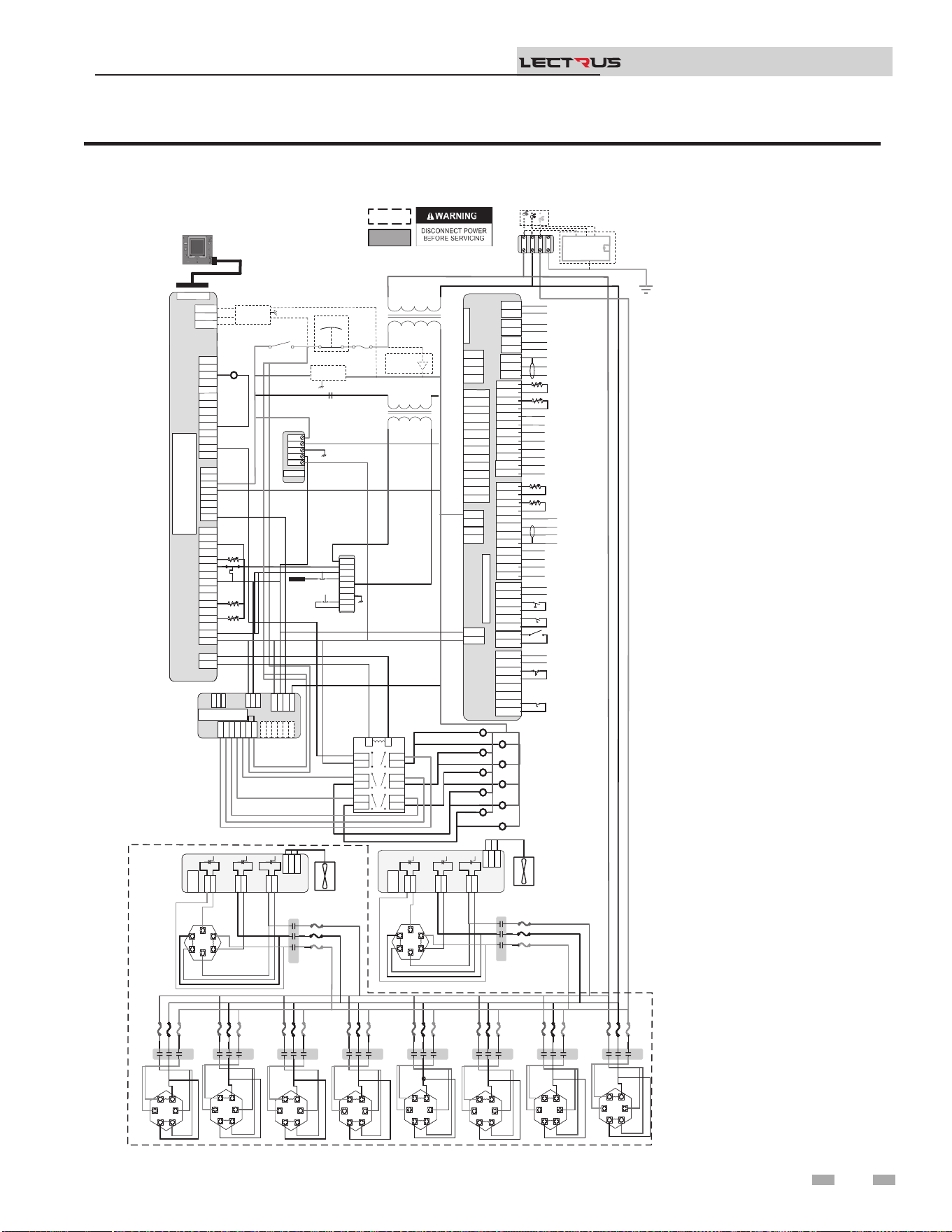
Figure 8-7 Ladder Diagram - 208V, 3 Phase
8 Diagrams (continued)
Installation & Operation Manual
TM
Notes:
1. Where possible, switches
are shown without utilities
(water or electricity)
connected to the unit.
As such, actual switch
states may vary from
those shown on diagrams
depending upon whether
utilities are connected, or
a fault condition is present.
2. See wiring diagram for
additional notes.
J2-1
J2-2
J2-3
J3-1
J3-2
J3-3
J3-4
J3-5
J3-6
J2-1
J2-2
J2-3
J3-1
J3-2
J3-3
J3-4
J3-5
J3-6
LWCO
Test
Reset
Probe
K2
K6
K8
K10
K4
K7
K5
K1
K3
K9
Outlet
Outlet
Inlet
System Pump (120VAC 0.75A Max)
CN5-1
CN5-2
CN5-3
CN5-1
CN5-2
CN5-3
DHW1
DHW2
DHW1
DHW2
SYS1
SYS2
SYS1
SYS2
BLR1
BLR2
BLR1
BLR2
CN3-1-1
CN3-1-2
CN3-1-3
CN3-1-4
CN3-1-5
CN3-1-6
CN3-1-7
CN3-1-8
CN3-1-1
CN3-1-2
CN3-1-3
CN3-1-4
CN3-1-5
CN3-1-6
CN3-1-7
CN3-1-8
CN3-2-1
CN3-2-2
CN3-2-3
CN3-2-4
CN3-2-5
CN3-2-6
CN3-2-7
CN3-2-8
CN3-2-1
CN3-2-2
CN3-2-3
CN3-2-4
CN3-2-5
CN3-2-6
CN3-2-7
CN3-2-8
J1-1
J1-2
J1-3
J1-4
J1-1
J1-2
J1-3
J1-4
CN9-1
CN9-2
CN9-3
CN9-4
CN9-1
CN9-2
CN9-3
CN9-4
CN4-1
CN4-2
CN4-3
CN4-4
CN4-5
CN4-6
CN4-7
CN4-8
CN4-9
CN4-10
CN4-11
CN4-12
CN4-13
CN4-14
CN4-1
CN4-2
CN4-3
CN4-4
CN4-5
CN4-6
CN4-7
CN4-8
CN4-9
CN4-10
CN4-11
CN4-12
CN4-13
CN4-14
Connecon Board
CN6 RIBBON
CN5-1
CN5-2
CN5-3
DHW1
DHW2
SYS1
SYS2
BLR1
BLR2
CN3-1-1
CN3-1-2
CN3-1-3
CN3-1-4
CN3-1-5
CN3-1-6
CN3-1-7
CN3-1-8
CN3-2-1
CN3-2-2
CN3-2-3
CN3-2-4
CN3-2-5
CN3-2-6
CN3-2-7
CN3-2-8
J1-1
J1-2
J1-3
J1-4
CN9-1
CN9-2
CN9-3
CN9-4
CN4-1
CN4-2
CN4-3
CN4-4
CN4-5
CN4-6
CN4-7
CN4-8
CN4-9
CN4-10
CN4-11
CN4-12
CN4-13
CN4-14
Connecon Board
CN6 RIBBON
DHW Pump (120VAC 0.75A Max)
Boiler Pump (120VACAC 0.75A Max)
Run Time Contacts
Low Pressure Switch
Flow Switch
Demand Enable
Alarm Contacts
DHW Demand
External LWCO
CN5-1
CN5-2
CN5-3
DHW1
DHW2
SYS1
SYS2
BLR1
BLR2
CN3-1-1
CN3-1-2
CN3-1-3
CN3-1-4
CN3-1-5
CN3-1-6
CN3-1-7
CN3-1-8
CN3-2-1
CN3-2-2
CN3-2-3
CN3-2-4
CN3-2-5
CN3-2-6
CN3-2-7
CN3-2-8
J1-1
J1-2
J1-3
J1-4
CN9-1
CN9-2
CN9-3
CN9-4
CN4-1
CN4-2
CN4-3
CN4-4
CN4-5
CN4-6
CN4-7
CN4-8
CN4-9
CN4-10
CN4-11
CN4-12
CN4-13
CN4-14
Connecon Board
CN6 RIBBON
A
Run Time Contacts
Low Pressure Switch
Flow Switch
Demand Enable
Alarm Contacts
DHW Demand
External LWCO
+V
-V
GND
N
L
+V
-V
GND
N
L
PSU
+V
-V
GND
N
L
PSU
X7-RIBBON
X4-1
X4-2
X4-3
X4-4
X4-5
X4-6
X4-7
X4-8
X4-9
X4-
X4-
X4-
X4-
X4-
X4-1
X4-2
X4-3
X4-4
X4-5
X4-6
X4-7
X4-8
X4-9
X4-
X4-
X4-
X4-
X4-
X5-1
X5-2
X5-3
X5-4
X5-5
X5-6
X5-7
X5-8
X5-9
X5-10
X5-11
X5-12
X5-13
X5-14
X5-15
X5-16
X5-1
X5-2
X5-3
X5-4
X5-5
X5-6
X5-7
X5-8
X5-9
X5-10
X5-11
X5-12
X5-13
X5-14
X5-15
X5-16
X1-1
X1-2
X1-3
X1-4
X1-5
X1-6
X1-7
X1-8
X1-1
X1-2
X1-3
X1-4
X1-5
X1-6
X1-7
X1-8
X2-1
X2-2
X2-1
X2-2
BIC
X4-1
X4-2
X4-3
X4-4
X4-5
X4-6
X4-7
X4-9
X4-
X4-
X4-
X4-
X4-
X5-1
X5-2
X5-3
X5-4
X5-5
X5-6
X5-7
X5-8
X5-9
X5-10
X5-11
X5-12
X5-13
X5-14
X5-15
X5-16
X1-1
X1-2
X1-3
X1-4
X1-5
X1-
X1-
X1-8
X2-1
X2-2
J27-1
J27-2
J27-1
J27-2
J1-1
J1-2
J1-3
J1-1
J1-2
J1-3
J8-1
J8-2
J8-3
J8-4
J8-5
J8-1
J8-2
J8-3
J8-4
J8-5
J16-1
J16-2
J16-3
J15-1
J15-2
J12-1
J12-2
J16-1
J16-2
J16-3
J15-1
J15-2
J12-1
J12-2
J10-1
J10-2
J10-3
J10-4
J10-5
J10-6
J10-1
J10-2
J10-3
J10-4
J10-5
J10-6
MCB
J27-1
J27-2
J1-1
J1-2
J1-3
J8-1
J8-2
J8-3
J8-4
J8-5
J16-1
J16-2
J16-3
J15-1
J15-2
J12-1
J12-2
J10-1
J10-2
J10-3
J10-4
J10-5
J10-6
MCB
J9-1
J9-2
J9-3
J9-1
J9-2
J9-3
J6-1
J5-1
J6-1
J5-1
J2-1
J1-1
J2-1
J1-1
J4-1
J3-1
J4-1
J3-1
TRIAC 2
K2K2
K1K1
1 2 3
1 2 3
1 2 3
1 2 3
BL
BL
BK
R
R
BK
1 2 3
1 2 3
1 2 3
1 2 3
BL
BL
BK
R
R
BK
K3
1 2 3
1 2 3
1 2 3
1 2 3
BK
R
BL
BL
BKR
K3
1 2 3
1 2 3
BK
R
BL
BL
BKR
K4K4
1 2 3
1 2 3
1 2 3
1 2 3
BK
R
BL
BL
BKR
K4
1 2 3
1 2 3
BK
R
BL
BL
BKR
K5
1 2 3
1 2 3
1 2 3
1 2 3
BK
R
BL
BL
BKR
K5
1 2 3
1 2 3
BK
R
BL
BL
BKR
K6
1 2 3
1 2 3
1 2 3
1 2 3
BK
R
BL
BL
BKR
K6
1 2 3
1 2 3
BK
R
BL
BL
BKR
K7
1 2 3
1 2 3
1 2 3
1 2 3
BK
R
BL
BL
BKR
K7
1 2 3
1 2 3
BK
R
BL
BL
BKR
K8
1 2 3
1 2 3
1 2 3
1 2 3
BK
R
BL
BL
BKR
K8
1 2 3
1 2 3
BK
R
BL
BL
BKR
K9
1 2 3
1 2 3
1 2 3
1 2 3
BK
R
BL
BL
BKR
K9
1 2 3
1 2 3
BK
R
BL
BL
BKR
K10
1 2 3
1 2 3
1 2 3
1 2 3
BK
R
BL
BL
BKR
K10
1 2 3
1 2 3
BK
R
BL
BL
BKR
R
BK
BL
R
BK
BL
R
BK
BL
R
BK
BL
R
BK
R
BK
R
BK
BL
R
BK
BL
R
BK
BL
R
BK
BL
3
4
7
8
11
12
5
6
9
10
13
14
1
2
3
4
7
8
11
12
5
6
9
10
13
14
1
2
LR
3
4
7
8
11
12
5
6
9
10
13
14
1
2
LR
J2-1
J2-2
J2-3
J3-1
J3-2
J3-3
J3-4
J3-5
J3-6
LWCO
Test
Reset
Probe
K2
K6
K8
K10
K4
R6 LWCO RELAY
K7
K5
K1
K3
K9
Outlet
Outlet
Inlet
CN5-1
CN5-2
CN5-3
DHW1
DHW2
SYS1
SYS2
BLR1
BLR2
CN3-1-1
CN3-1-2
CN3-1-3
CN3-1-4
CN3-1-5
CN3-1-6
CN3-1-7
CN3-1-8
CN3-2-1
CN3-2-2
CN3-2-3
CN3-2-4
CN3-2-5
CN3-2-6
CN3-2-7
CN3-2-8
J1-1
J1-2
J1-3
J1-4
CN9-1
CN9-2
CN9-3
CN9-4
CN4-1
CN4-2
CN4-3
CN4-4
CN4-5
CN4-6
CN4-7
CN4-8
CN4-9
CN4-10
CN4-11
CN4-12
CN4-13
CN4-14
Connecon Board
CN6 RIBBON
Shield
B
Run Time Contacts
Low Pressure Switch
Flow Switch
Demand Enable
Alarm Contacts
DHW Demand
External LWCO
+V
-V
GND
N
L
24VDC PSU
X4-1
X4-2
X4-3
X4-4
X4-5
X4-6
X4-7
X4-8
X4-9
X4
-
10
X4-11
X4-12
X4-13
X4-14
X5-1
X5-2
X5-3
X5-4
X5-5
X5-6
X5-7
X5-8
X5-9
X5-10
X5-11
X5-12
X5-13
X5-14
X5-15
X5-16
X1-1
X1-2
X1-3
X1-4
X1-5
X1
-
6
X1-7
X1-8
X2-1
X2-2
J9-1
J9-2
J9-3
J6-1
J5-1
J2-1
J1-1
J4-1
J3-1
TRIAC 2
K2
K1
1 2 3
1 2 3
BL
BL
BK
R
R
BK
1 2 3
1 2 3
BL
BL
BK
R
R
BK
K3
1 2 3
1 2 3
BK
R
BL
BL
BKR
K4
1 2 3
1 2 3
BK
R
BL
BL
BKR
K5
1 2 3
1 2 3
BK
R
BL
BL
BKR
K6
1 2 3
1 2 3
BK
R
BL
BL
BKR
K7
1 2 3
1 2 3
BK
R
BL
BL
BKR
K8
1 2 3
1 2 3
BK
R
BL
BL
BKR
K9
1 2 3
1 2 3
BK
R
BL
BL
BKR
K10
1 2 3
1 2 3
BK
R
BL
BL
BKR
BK
BL
BL
BL
R
BK
BL
R
BK
BL
3
4
7
8
11
12
5
6
9
10
13
14
1
2
LR
GND
YTICAPAC GNITAEH WK TINU NO TNEDNEPED SI STNEMELE & SROTCATNOC FO REBMUN LAUTCA :ETON
CN1-1
CN1-2
CN1-3
CN1-4
CN1-5
CN1-6
CN1-7
CN1-8
CN1-9
CN1-10
CN1-11
CN1-12
CN1-1
CN1-2
CN1-3
CN1-4
CN1-5
CN1-6
CN1-7
CN1-8
CN1-9
CN1-10
CN1-11
CN1-12
Outdoor Sensor
Tank Sensor
System Sensor
DHW Recirc Sensor
CN2-1
CN2-2
CN2-3
CN2-4
CN2-5
CN2-6
CN2-7
CN2-8
CN2-9
CN2-10
CN2-11
CN2-12
CN2-1
CN2-2
CN2-3
CN2-4
CN2-5
CN2-6
CN2-7
CN2-8
CN2-9
CN2-10
CN2-12
-
+ Alarm Power
-
+ Alarm Power
-
+ 0-10V Rate Out
-
+ 0-10V Rate Out
-
+ 0-10V System Out
-
+ 0-10V System Out
-
+ 0-10V BMS In
-
+ 0-10V BMS In
Shield
Shield
Cascade
-
+ 0-10V System Pump In
-
+ 0-10V System Pump In
-
+ CT Power
-
+ CT Power
CN1-1
CN1-2
CN1-3
CN1-4
CN1-5
CN1-6
CN1-7
CN1-8
CN1-9
CN1-10
CN1-11
CN1-12
Outdoor Sensor
Tank Sensor
System Sensor
DHW Recirc Sensor
CN2-12
CN2-11
CN2-10
CN2-9
CN2-8
CN2-7
CN2-6
CN2-5
CN2-4
CN2-3
CN2-2
CN2-1
-
+ Alarm Power
-
+ 0-10V Rate Out
-
+ 0-10V System Out
-
+ 0-10V BMS In
Shield
Shield
Cascade
-
+ 0-10V System Pump In
-
+ CT Power
J9-1
J9-2
J9-3
J9-1
J9-2
J9-3
J6-1
J5-1
J6-1
J5-1
J2-1
J1-1
J2-1
J1-1
J4-1
J3-1
J4-1
J3-1
TRIAC 1
BL BK
R
J9-1
J9-2
J9-3
J6-1
J5-1
J2-1
J1-1
J4-1
J3-1
TRIAC 1
BL BK
R
.
.
.
.
.
.
.
.
. .
.
.
.
.
.
.
.
.
.
.
.
.
.
.
.
.
.
.
.
.
.
.
.
.
.
.
.
.
.
.
.
.
.
.
.
.
.
.
.
.
.
.
BOX DEPICTS
OPTIONAL ITEMS
BOX DEPICTS
DUAL SENSOR
SINGLE HOUSING
100374101 REV F
MRHL
.
J2
-1
J2-2
.
.
208 VAC 3 ɸ
GNDGND
L3L3
L2L2
L1L1
GND
L3
L2
L1
RED
BLK
BLU
Oponal Current Transformers
For Power Meter
.
.
.
Main Voltage
120 VAC
120V
24VAC
R6
Fuse
Power
On/Off
E-Stop
Safety
Interlock
.
.
.
.
J27-1
J27-2
J1-1
J1-2
J1-3
J8-1
J8-2
J8-3
J16-1
J16-2
J16-3
J15-1
J15-2
J12-1
J12-2
J10-1
J10-2
J10-3
J10-4
J10-5
J10-6
MODULATION CONTROL
BOARD (MCB)
J17-2
J17-1
.
.
.
DISPLAY
POWER
METER
L
N
GND
.
.
BOILER INTERGRATED CONTROL
(BIC)
Safety
Monitor
Relay
TRIAC Fan
TRIAC Fan
.
16
17
Relay
Output
7
8
9
19
Ground Fault
Protector
X9-3
X9-2
X9-1
MODBUS/
BACNET
.
X7
-
RIBBON
65
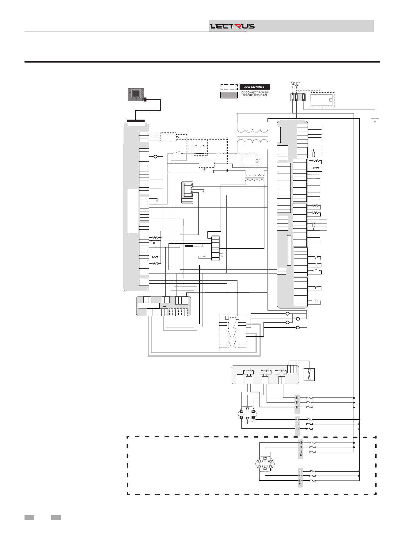
Figure 8-8 Ladder Diagram - 240V, 1 Phase
8 Diagrams
Installation & Operation Manual
TM
Notes:
1. Where possible, switches
are shown without utilities
(water or electricity)
connected to the unit.
As such, actual switch
states may vary from
those shown on diagrams
depending upon whether
utilities are connected, or
a fault condition is present.
2. See wiring diagram for
additional notes.
J2-1
J2-2
J2-3
J3-1
J3-2
J3-3
J3-4
J3-5
J3-6
J2-1
J2-2
J2-3
J3-1
J3-2
J3-3
J3-4
J3-5
J3-6
Main Voltage
120 VAC
120V
24VAC
LWCO
Test
Reset
Probe
R6
R6 LWCO RELAY
Outlet
Outlet
Inlet
System Pump (120VAC 0.75A Max)
CN5-1
CN5-2
CN5-3
CN5-1
CN5-2
CN5-3
DHW1
DHW2
DHW1
DHW2
SYS1
SYS2
SYS1
SYS2
BLR1
BLR2
BLR1
BLR2
CN3-1-1
CN3-1-2
CN3-1-3
CN3-1-4
CN3-1-5
CN3-1-6
CN3-1-7
CN3-1-8
CN3-1-1
CN3-1-2
CN3-1-3
CN3-1-4
CN3-1-5
CN3-1-6
CN3-1-7
CN3-1-8
CN3-2-1
CN3-2-2
CN3-2-3
CN3-2-4
CN3-2-5
CN3-2-6
CN3-2-7
CN3-2-8
CN3-2-1
CN3-2-2
CN3-2-3
CN3-2-4
CN3-2-5
CN3-2-6
CN3-2-7
CN3-2-8
J1-1
J1-2
J1-3
J1-4
J1-1
J1-2
J1-3
J1-4
CN9-1
CN9-2
CN9-3
CN9-4
CN9-1
CN9-2
CN9-3
CN9-4
CN4-1
CN4-2
CN4-3
CN4-4
CN4-5
CN4-6
CN4-7
CN4-8
CN4-9
CN4-10
CN4-11
CN4-12
CN4-13
CN4-14
CN4-1
CN4-2
CN4-3
CN4-4
CN4-5
CN4-6
CN4-7
CN4-8
CN4-9
CN4-10
CN4-11
CN4-12
CN4-13
CN4-14
Connecon Board
CN6 RIBBON
CN5-1
CN5-2
CN5-3
DHW1
DHW2
SYS1
SYS2
BLR1
BLR2
CN3-1-1
CN3-1-2
CN3-1-3
CN3-1-4
CN3-1-5
CN3-1-6
CN3-1-7
CN3-1-8
CN3-2-1
CN3-2-2
CN3-2-3
CN3-2-4
CN3-2-5
CN3-2-6
CN3-2-7
CN3-2-8
J1-1
J1-2
J1-3
J1-4
CN9-1
CN9-2
CN9-3
CN9-4
CN4-1
CN4-2
CN4-3
CN4-4
CN4-5
CN4-6
CN4-7
CN4-8
CN4-9
CN4-10
CN4-11
CN4-12
CN4-13
CN4-14
Connecon Board
CN6 RIBBON
DHW Pump (120VAC 0.75A Max)
Boiler Pump (120VAC 0.75 Max)
A
Run Time Contacts
Low Pressure Switch
Flow Switch
Demand Enable
Alarm Contacts
DHW Demand
External LWCO
CN5-1
CN5-2
CN5-3
DHW1
DHW2
SYS1
SYS2
BLR1
BLR2
CN3-1-1
CN3-1-2
CN3-1-3
CN3-1-4
CN3-1-5
CN3-1-6
CN3-1-7
CN3-1-8
CN3-2-1
CN3-2-2
CN3-2-3
CN3-2-4
CN3-2-5
CN3-2-6
CN3-2-7
CN3-2-8
J1-1
J1-2
J1-3
J1-4
CN9-1
CN9-2
CN9-3
CN9-4
CN4-1
CN4-2
CN4-3
CN4-4
CN4-5
CN4-6
CN4-7
CN4-8
CN4-9
CN4-10
CN4-11
CN4-12
CN4-13
CN4-14
Connecon Board
CN6 RIBBON
Shield
B
Run Time Contacts
Low Pressure Switch
Flow Switch
Demand Enable
Alarm Contacts
DHW Demand
External LWCO
+V
-V
GND
N
L
+V
-V
GND
N
L
PSU
+V
-V
GND
N
L
24 VDC PSU
X7-RIBBON
X4-1
X4-2
X4-3
X4-4
X4-5
X4-6
X4-7
X4-8
X4-9
X4-10
X4-11
X4-12
X4-13
X4-14
X4-1
X4-2
X4-3
X4-4
X4-5
X4-6
X4-7
X4-8
X4-9
X4-10
X4-11
X4-12
X4-13
X4-14
X5-1
X5-2
X5-3
X5-4
X5-5
X5-6
X5-7
X5-8
X5-9
X5-10
X5-11
X5-12
X5-13
X5-14
X5-15
X5-16
X5-1
X5-2
X5-3
X5-4
X5-5
X5-6
X5-7
X5-8
X5-9
X5-10
X5-11
X5-12
X5-13
X5-14
X5-15
X5-16
X1-1
X1-2
X1-3
X1-4
X1-5
X1-6
X1-7
X1-8
X1-1
X1-2
X1-3
X1-4
X1-5
X1-6
X1-7
X1-8
X2-1
X2-2
X2-1
X2-2
BIC
X7
-
RIBBON
X4-1
X4-2
X4-3
X4-4
X4-5
X4-6
X4-7
X4-8
X4-9
X4-10
X4-11
X4-12
X4-13
X4-14
X5-1
X5-2
X5-3
X5-4
X5-5
X5-6
X5-7
X5-8
X5-9
X5-10
X5-11
X5-12
X5-13
X5-14
X5-15
X5-16
X1-1
X1-2
X1-3
X1-4
X1-5
X1-6
X1-7
X1-8
X2-1
X2-2
J27-1
J27-2
J27-1
J27-2
J1-1
J1-2
J1-3
J1-1
J1-2
J1-3
J8-1
J8-2
J8-3
J8-4
J8-5
J8-1
J8-2
J8-3
J8-4
J8-5
J16-1
J16-2
J16-3
J15-1
J15-2
J12-1
J12-2
J16-1
J16-2
J16-3
J15-1
J15-2
J12-1
J12-2
J10-1
J10-2
J10-3
J10-4
J10-5
J10-6
J10-1
J10-2
J10-3
J10-4
J10-5
J10-6
MCB
K2K2
K1K1
1 2 3
1 2 3
1 2 3
1 2 3
3
4
7
8
11
12
5
6
9
10
13
14
1
2
3
4
7
8
11
12
5
6
9
10
13
14
1
2
LR
3
4
7
8
11
12
5
6
9
10
13
14
1
2
LR
GND
CN1-1
CN1-2
CN1-3
CN1-4
CN1-5
CN1-6
CN1-7
CN1-8
CN1-9
CN1-10
CN1-11
CN1-12
CN1-1
CN1-2
CN1-3
CN1-4
CN1-5
CN1-6
CN1-7
CN1-8
CN1-9
CN1-10
CN1-11
CN1-12
Outdoor Sensor
Tank Sensor
System Sensor
DHW Recirc Sensor
CN2-1
CN2-2
CN2-3
CN2-4
CN2-5
CN2-6
CN2-7
CN2-8
CN2-9
CN2-10
CN2-11
CN2-12
CN2-1
CN2-2
CN2-3
CN2-4
CN2-5
CN2-6
CN2-7
CN2-8
CN2-9
CN2-10
CN2-11
CN2-12
-
+ Alarm Power
-
+ Alarm Power
-
+ 0-10V Rate Out
-
+ 0-10V Rate Out
-
+ 0-10V System Out
-
+ 0-10V System Out
-
+ 0-10V BMS In
-
+ 0-10V BMS In
Shield
Shield
Cascade
-
+ 0-10V System Pump In
-
+ 0-10V System Pump In
-
+ CT Power
-
+ CT Power
CN1-1
CN1-2
CN1-3
CN1-4
CN1-5
CN1-6
CN1-7
CN1-8
CN1-9
CN1-10
CN1-11
CN1-12
Outdoor Sensor
Tank Sensor
System Sensor
DHW Recirc Sensor
CN2-12
CN2-11
CN2-10
CN2-9
CN2-8
CN2-7
CN2-6
CN2-5
CN2-4
CN2-3
CN2-2
CN2-1
-
+ Alarm Power
-
+ 0-10V Rate Out
-
+ 0-10V System Out
-
+ 0-10V BMS In
Shield
Shield
Cascade
-
+ 0-10V System Pump In
-
+ CT Power
J9-1
J9-2
J9-3
J9-1
J9-2
J9-3
J6-1
J5-1
J6-1
J5-1
J2-1
J1-1
J2-1
J1-1
J4-1
J3-1
J4-1
J3-1
TRIAC 1
J9-1
J9-2
J9-3
J6-1
J5-1
J2-1
J1-1
J4-1
J3-1
TRIAC 1
.
.
.
. .
.
.
.
NOTE: ACTUAL NUMBER OF CONTACTORS & ELEMENTS IS DEPENDENT ON UNIT KW HEATING CAPACITY
K2
K4
K1
K3
.
.
.
.
BOX DEPICTS
OPTIONAL ITEMS
BOX DEPICTS
DUAL SENSOR
SINGLE HOUSING
100374924 REV E
MRHL
J27-1
J27-2
J1-1
J1-2
J1-3
J8-1
J8-2
J8-3
J16-1
J16-2
J16-3
J15-1
J15-2
J12-1
J12-2
J10-1
J10-2
J10-3
J10-4
J10-5
J10-6
J17-2
J17-1
.
J2
-1
J2-2
.
.
240 VAC 1 ɸ
GNDGND
L3L3
L2L2
L1L1
GND
L2
L1
RED
BLK
Oponal Current Transformers
For Power Meter
.
.
Power
On/Off
E-Stop
Safety
Interlock
.
.
.
.
RED
RED
RED
RED
RED
RED
RED
BLK
BLU
RED
RED
RED
RED
RED
RED
BLK
BLK
BLK
RED
BLK
BLU
RED
BLK
BLU
RED
RED
RED
BLK
BLK
BLK
RED
BLK
BLU
.
BOILER INTERGRATED CONTROL
(BIC)
DISPLAY
.
.
16
17
Relay
Output
19
Ground Fault
Protector
7
8
Safety
Monitor
Relay
MODULATION CONTROL
BOARD (MCB)
TRIAC Fan
.
.
POWER
METER
L
N
.
.
GND
GND
GND
GND
X9-3
X9-2
X9-1
MODBUS/
BACNET
.
66
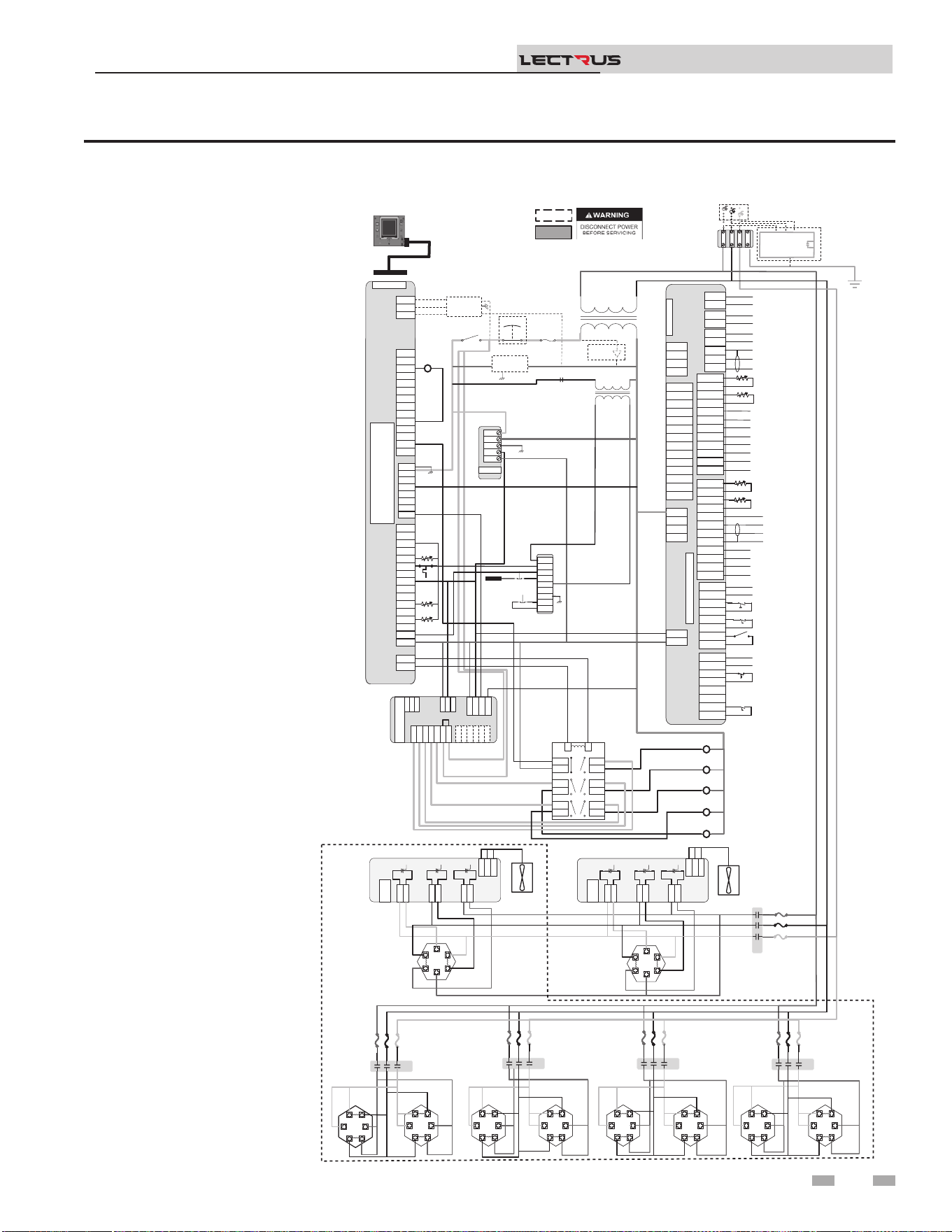
Figure 8-9 Ladder Diagram - 400-600V, 3 Phase
8 Diagrams (continued)
Installation & Operation Manual
TM
Notes:
1. Where possible, switches
are shown without utilities
(water or electricity)
connected to the unit.
As such, actual switch
states may vary from
those shown on diagrams
depending upon whether
utilities are connected, or
a fault condition is present.
2. See wiring diagram for
additional notes.
Main Voltage
120 VAC
120V
24VAC
R6
Fuse
Power
On/Off
E-Stop
Safety
Interlock
.
.
.
J2-1
J2-2
J2-3
J3-1
J3-2
J3-3
J3-4
J3-5
J3-6
J2-1
J2-2
J2-3
J3-1
J3-2
J3-3
J3-4
J3-5
J3-6
LWCO
Test
Reset
Probe
R6 LWCO RELAY
K4
K3
K1
K2
K5
Outlet
Outlet
Inlet
System Pump (120VAC 0.75Max)
CN5-1
CN5-2
CN5-3
CN5-1
CN5-2
CN5-3
DHW1
DHW2
DHW1
DHW2
SYS1
SYS2
SYS1
SYS2
BLR1
BLR2
BLR1
BLR2
CN3-1-1
CN3-1-2
CN3-1-3
CN3-1-4
CN3-1-5
CN3-1-6
CN3-1-7
CN3-1-8
CN3-1-1
CN3-1-2
CN3-1-3
CN3-1-4
CN3-1-5
CN3-1-6
CN3-1-7
CN3-1-8
CN3-2-1
CN3-2-2
CN3-2-3
CN3-2-4
CN3-2-5
CN3-2-6
CN3-2-7
CN3-2-8
CN3-2-1
CN3-2-2
CN3-2-3
CN3-2-4
CN3-2-5
CN3-2-6
CN3-2-7
CN3-2-8
J1-1
J1-2
J1-3
J1-4
J1-1
J1-2
J1-3
J1-4
CN9-1
CN9-2
CN9-3
CN9-4
CN9-1
CN9-2
CN9-3
CN9-4
CN4-1
CN4-2
CN4-3
CN4-4
CN4-5
CN4-6
CN4-7
CN4-8
CN4-9
CN4-10
CN4-11
CN4-12
CN4-13
CN4-14
CN4-1
CN4-2
CN4-3
CN4-4
CN4-5
CN4-6
CN4-7
CN4-8
CN4-9
CN4-10
CN4-11
CN4-12
CN4-13
CN4-14
Connecon Board
CN6 RIBBON
CN5-1
CN5-2
CN5-3
DHW1
DHW2
SYS1
SYS2
BLR1
BLR2
CN3-1-1
CN3-1-2
CN3-1-3
CN3-1-4
CN3-1-5
CN3-1-6
CN3-1-7
CN3-1-8
CN3-2-1
CN3-2-2
CN3-2-3
CN3-2-4
CN3-2-5
CN3-2-6
CN3-2-7
CN3-2-8
J1-1
J1-2
J1-3
J1-4
CN9-1
CN9-2
CN9-3
CN9-4
CN4-1
CN4-2
CN4-3
CN4-4
CN4-5
CN4-6
CN4-7
CN4-8
CN4-9
CN4-10
CN4-11
CN4-12
CN4-13
CN4-14
Connecon Board
CN6 RIBBON
DHW Pump (120VAC 0.75Max)
Boiler Pump (120VAC 0.75Max)
A
B
Run Time Contacts
Low Pressure Switch
Flow Switch
Demand Enable
Alarm Contacts
DHW Demand
External LWCO
CN5-1
CN5-2
CN5-3
DHW1
DHW2
SYS1
SYS2
BLR1
BLR2
CN3-1-1
CN3-1-2
CN3-1-3
CN3-1-4
CN3-1-5
CN3-1-6
CN3-1-7
CN3-1-8
CN3-2-1
CN3-2-2
CN3-2-3
CN3-2-4
CN3-2-5
CN3-2-6
CN3-2-7
CN3-2-8
J1-1
J1-2
J1-3
J1-4
CN9-1
CN9-2
CN9-3
CN9-4
CN4-1
CN4-2
CN4-3
CN4-4
CN4-5
CN4-6
CN4-7
CN4-8
CN4-9
CN4-10
CN4-11
CN4-12
CN4-13
CN4-14
Connecon Board
CN6 RIBBON
DHW Pump (
Boiler Pump (
Shield
Run Time Contacts
Low Pressure Switch
Flow Switch
Demand Enable
Alarm Contacts
DHW Demand
External LWCO
+V
-V
GND
N
L
+V
-V
GND
N
L
PSU
+V
-V
GND
N
L
24VDC PSU
X7-RIBBON
X4-1
X4-2
X4-3
X4-4
X4-5
X4-6
X4-7
X4-8
X4-9
X4-10
X4-11
X4-12
X4-13
X4-14
X4-1
X4-2
X4-3
X4-4
X4-5
X4-6
X4-7
X4-8
X4-9
X4-10
X4-11
X4-12
X4-13
X4-14
X5-1
X5-2
X5-3
X5-4
X5-5
X5-6
X5-7
X5-8
X5-9
X5-10
X5-11
X5-12
X5-13
X5-14
X5-15
X5-16
X5-1
X5-2
X5-3
X5-4
X5-5
X5-6
X5-7
X5-8
X5-9
X5-10
X5-11
X5-12
X5-13
X5-14
X5-15
X5-16
X1-1
X1-2
X1-3
X1-4
X1-5
X1-6
X1-7
X1-8
X1-1
X1-2
X1-3
X1-4
X1-5
X1-6
X1-7
X1-8
X2-1
X2-2
X2-1
X2-2
BIC
X7
-
RIBBON
X4-1
X4-2
X4-3
X4-4
X4-5
X4-6
X4-7
X4-8
X4-9
X4-10
X4-11
X4-12
X4-13
X4-14
X5-1
X5-2
X5-3
X5-4
X5-5
X5-6
X5-7
X5-8
X5-9
X5-10
X5-11
X5-12
X5-13
X5-14
X5-15
X5-16
X1-1
X1-2
X1-3
X1-4
X1-5
X1-6
X1-7
X1-8
X2-1
X2-2
J27-1
J27-2
J27-1
J27-2
J1-1
J1-2
J1-3
J1-1
J1-2
J1-3
J8-1
J8-2
J8-3
J8-4
J8-5
J8-1
J8-2
J8-3
J8-4
J8-5
J16-1
J16-2
J16-3
J15-1
J15-2
J12-1
J12-2
J16-1
J16-2
J16-3
J15-1
J15-2
J12-1
J12-2
J10-1
J10-2
J10-3
J10-4
J10-5
J10-6
J10-1
J10-2
J10-3
J10-4
J10-5
J10-6
MCB
J27-1
J27-2
J1-1
J1-2
J1-3
J8-1
J8-2
J8-3
J16-1
J16-2
J16-3
J15-1
J15-2
J12-1
J12-2
J10-1
J10-2
J10-3
J10-4
J10-5
J10-6
MONITORING CONTROL
BOARD(MCB)
J9-1
J9-2
J9-3
J9-1
J9-2
J9-3
J6-1
J5-1
J6-1
J5-1
J2-1
J1-1
J2-1
J1-1
J4-1
J3-1
J4-1
J3-1
TRIAC 2
3
4
7
8
11
12
5
6
9
10
13
14
1
2
3
4
7
8
11
12
5
6
9
10
13
14
1
2
LR
3
4
7
8
11
12
5
6
9
10
13
14
1
2
LR
480/600VAC 3 ɸ
GND
YTICAPAC GNITAEH WK TINU NO TNEDNEPED SI STNEMELE & SROTCATNOC FO REBMUN LAUTCA :ETON
CN1-1
CN1-2
CN1-3
CN1-4
CN1-5
CN1-6
CN1-7
CN1-8
CN1-9
CN1-10
CN1-11
CN1-12
CN1-1
CN1-2
CN1-3
CN1-4
CN1-5
CN1-6
CN1-7
CN1-8
CN1-9
CN1-10
CN1-11
CN1-12
Outdoor Sensor
Tank Sensor
System Sensor
DHW Recirc Sensor
CN2-1
CN2-2
CN2-3
CN2-4
CN2-5
CN2-6
CN2-7
CN2-8
CN2-9
CN2-10
CN2-11
CN2-12
CN2-1
CN2-2
CN2-3
CN2-4
CN2-5
CN2-6
CN2-7
CN2-8
CN2-9
CN2-10
CN2-11
CN2-12
-
+ Alarm Power
-
+ Alarm Power
-
+ 0-10V Rate Out
-
+ 0-10V Rate Out
-
+ 0-10V System Out
-
+ 0-10V System Out
-
+ 0-10V BMS In
-
+ 0-10V BMS In
Shield
Shield
Cascade
-
+ 0-10V System Pump In
-
+ 0-10V System Pump In
-
+ CT Power
-
+ CT Power
CN1-1
CN1-2
CN1-3
CN1-4
CN1-5
CN1-6
CN1-7
CN1-8
CN1-9
CN1-10
CN1-11
CN1-12
Outdoor Sensor
Tank Sensor
System Sensor
DHW Recirc Sensor
CN2-12
CN2-11
CN2-10
CN2-9
CN2-8
CN2-7
CN2-6
CN2-5
CN2-4
CN2-3
CN2-2
CN2-1
-
+ Alarm Power
-
+ 0-10V Rate Out
-
+ 0-10V System Out
-
+ 0-10V BMS In
Shield
Shield
Cascade
-
+ 0-10V System Pump In
-
+ CT Power
J9-1
J9-2
J9-3
J9-1
J9-2
J9-3
J6-1
J5-1
J6-1
J5-1
J2-1
J1-1
J2-1
J1-1
J4-1
J3-1
J4-1
J3-1
TRIAC 1
J9-1
J9-2
J9-3
J6-1
J5-1
J2-1
J1-1
J4-1
J3-1
TRIAC 1
RED
.
.
.
.
.
.
.
. .
.
.
.
1 2 3
1 2 3
1 2 3
1 2 3
1 2 3
1 2 3
1 2 3
1 2 3
1 2 3
1 2 3
BL
1 2 3
1 2 3
1 2 3
1 2 3
1 2 3
1 2 3
1 2 3
1 2 3
1 2 3
1 2 3
1 2 3
1 2 3
1 2 3
1 2 3
1 2 3
1 2 3
1 2 3
1 2 3
K3K5
RED
BLK
BLU
K5K4
K7K3
1 2 3
1 2 3
1 2 3
1 2 3
1 2 3
1 2 3
1 2 3
1 2 3
1 2 3
1 2 3
1 2 3
1 2 3
1 2 3
1 2 3
1 2 3
1 2 3
K9K2
1 2 3
1 2 3
1 2 3
1 2 3
1 2 3
1 2 3
1 2 3
1 2 3
1 2 3
1 2 3
1 2 3
1 2 3
1 2 3
1 2 3
1 2 3
1 2 3
.
.
.
.
.
.
.
.
.
.
.
.
.
.
.
.
.
.
.
.
.
.
.
.
.
.
.
.
.
.
.
.
.
K1K1
RED
BLK
BLU
1 2 3
1 2 3
1 2 3
1 2 3
1 2 3
1 2 3
1 2 3
1 2 3
1 2 3
1 2 3
1 2 3
1 2 3
.
.
.
.
.
.
.
.
.
.
.
.
.
.
.
.
.
100374954 REV E
BOX DEPICTS
OPTIONAL ITEMS
BOX DEPICTS
DUAL SENSOR
SINGLE HOUSING
MRHL
J17-1
J17-2
.
J2
-1
J2-2
.
.
GNDGND
L3L3
L2L2
L1L1
GND
L3
L2
L1
RED
BLK
BLU
Oponal Current Transformers
For Power Meter
.
.
.
.
.
.
.
.
.
BLK
BLU
BLU
BLK
BLK
BLU
RED
RED
BLK
BLU
BLU
BLK
BLK
BLU
RED
RED
RED
RED
BLK
BLU
RED
BLK
BLU
RED
BLK
BLU
BLK
BLU
BLK
BLU
RED
RED
BLK
BLU
BLK
BLU
RED
RED
.
BLK
BLU
BLK
BLU
RED
RED
BLK
BLU
BLK
BLU
RED
RED
.
BLK
BLU
BLK
BLU
RED
RED
BLK
BLU
BLK
BLU
RED
RED
.
BLK
BLU
BLK
BLU
RED
RED
BLK
BLU
BLK
BLU
RED
RED
.
DISPLAY
BOILER INTERGRATED CONTROL
(BIC)
Safety
Monitor
Relay
TRIAC Fan
TRIAC Fan
.
16
17
Relay
Output
1
3
5
19
Ground Fault
Protector
POWER
METER
L
N
GND
.
.
.
GND
GND
X9-3
X9-2
X9-1
MODBUS/
BACNET
.
67

Revision Notes: Revision A (PCP #3000058503 / CN #500044576)
initial release.
Revison B (PCP #3000059588 / CN #500045650) relfects updated
images throughout.
Revision C (PCP #3000061190 / CN #500047088) reects updates to
table 4A.
Revision D (PCP #3000061447 / CN #500047320) reects updates on
page 4 and gure 6-2.
Revision E (PCP #3000063264 / CN #500049042) reects updates to
gure 3-4.
Revision F (PCP #3000063785 / CN #500049627) reects changes
throughout, including updated diagrams.
Revision G (PCP #3000065374 / CN #500051019) reects updates
throughout, including updating diagrams.
Revision H (PCP #3000067298 / CN #500052845) reects updates to
table 4A.
Revision J (PCP #3000067924 / CN #500053443) reects the addition
of the product summary to pages 7 & 8.
Revision K (PCP #3000069836 / CN #500055226) reects an update to
the product summary.
100376295_2000786840_Rev K
12/25