Ventura
Bollerwagen
Handcart
Carros
Chariots
Carrelli
10030403 10034736 10034794 10034795


3
DE
English 17
Français 27
Español 39
Italiano 51
Sehr geehrter Kunde,
wir gratulieren Ihnen zum Erwerb Ihres Gerätes. Lesen
Sie die folgenden Hinweise sorgfältig durch und befolgen
Sie diese, um möglichen Schäden vorzubeugen. Für
Schäden, die durch Missachtung der Hinweise und
unsachgemäßen Gebrauch entstehen, übernehmen wir
keine Haftung. Scannen Sie den QR-Code, um Zugriff
auf die aktuellste Bedienungsanleitung und weitere
Informationen rund um das Produkt zu erhalten.
INHALTSVERZEICHNIS
Teileliste 4
Zusammenbau der Hinterachse 8
Zusammenbau der Vorderachse 9
Montage der Räder 11
Montage des Handzugs 12
Montage der Wände 12
HERSTELLER & IMPORTEUR (UK)
Hersteller:
Chal-Tec GmbH, Wallstraße 16, 10179 Berlin, Deutschland.
Importeur für Großbritannien:
Berlin Brands Group UK Limited
PO Box 42
272 Kensington High Street
London, W8 6ND
United Kingdom

4
DE
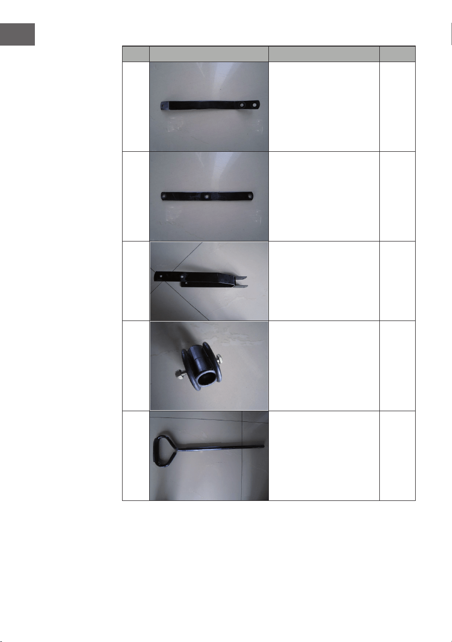
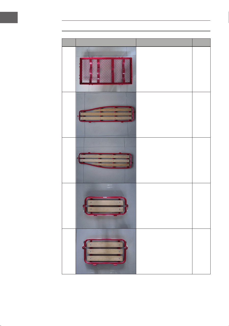
TEILELISTE
Nr. Bild Beschreibung Stk.
1
Boden 1
2
Linke Seitenwand 1
3
Rechte Seitenwand 1
4
Vorderwand 1
5
Rückwand 1

5
DE
Nr. Bild Beschreibung Stk.
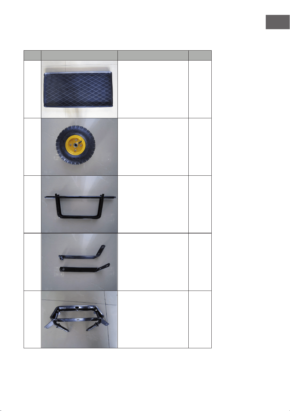
6
Einlage 1
7
Einlage 4
8
Rad 1
9
Hintere Achshalterung 2
10
Hintere Achsführung 1

6
DE
Nr. Bild Beschreibung Stk.
11
Mittlere Achsführung
vorne
1
12
Lenkanschluss 1
13
Gabel 1
14
Verbinder aus Kunststoff 1
15
Zuggriff 1
7
DE
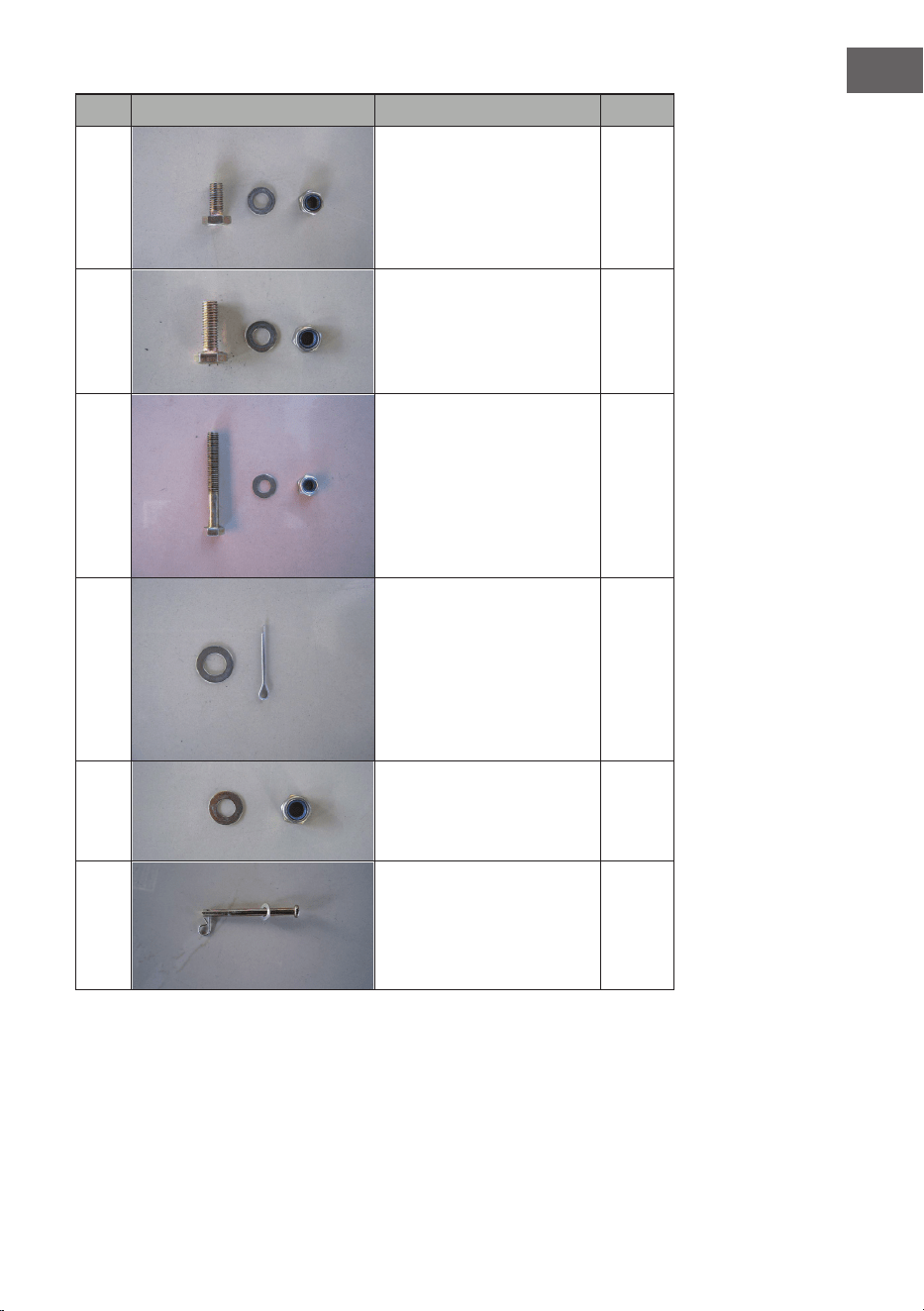
Nr. Bild Beschreibung Stk.
16
M8X18 Schraube
Unterlegscheibe
Mutter
13
17
M8X25 Schraube
Unterlegscheibe
Mutter
1
18
M8X60 Schraube
Unterlegscheibe
Mutter
1
19
M11 Unterlegscheibe
Bundbolzen
1
20
Unterlegscheibe M12
Kontermutter
4
21
Wand-Montagebolzen
M7 Unterlegscheibe
Federstecker
4

8
DE
ZUSAMMENBAU DER HINTERACHSE
1. Legen Sie den Boden (1) umgedreht hin.
2. Setzen Sie die hintere Achshalterung (8) an den Boden (1) an. Machen Sie
die Bohrlöcher der hinteren Achshalterung (8) mit den Löchern auf dem
hinteren Teil des Bodens (1) bündig. Legen Sie Schrauben (16) von unten
durch die bündigen Löcher. Bringen Sie die Unterlegscheiben (16) und die
Muttern an den Enden der Schrauben an.
3. Setzen Sie das linke Ende der hinteren Achsführung (9) auf die linke Seite
der hinteren Achshalterung (8) mit den angeschweißten Distanzhülsen
nach außen. Wiederholen Sie diesen Schritt für die rechte Seite.
9
DE
4. RichtenSiedieBohrungenandenachenEndenderlinkenSeiteder
hinteren Achsführung (9) mit den Bohrungen am Boden (1) aus. Führen
Sie die Schrauben (16) von der Unterseite des Bodens in die bündig
ausgerichteten Bohrungen. Legen Sie eine Unterlegscheibe (16) über die
Schrauben und schrauben Sie jeweils eine Mutter (16) rauf.
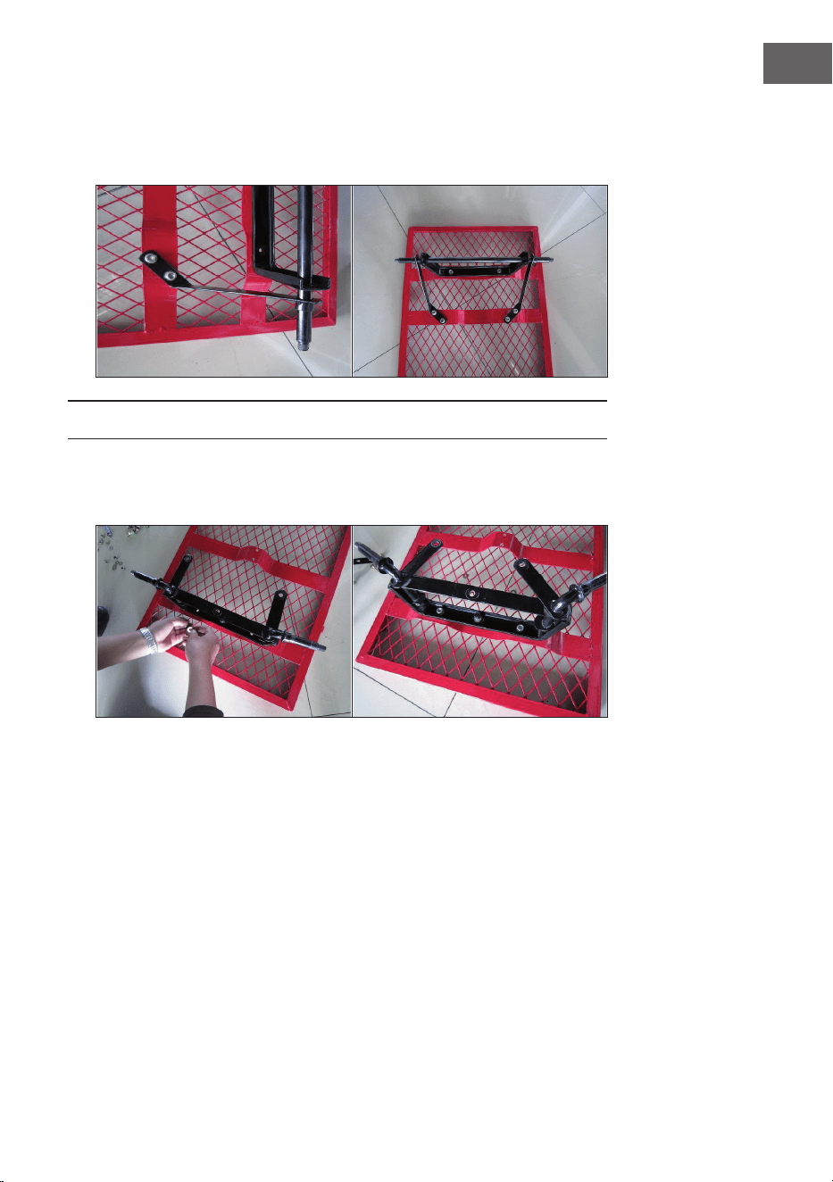
ZUSAMMENBAU DER VORDERACHSE
1. Vordere Achshalterung (10) am Boden vorne (1) anbringen. Die
Bohrungen ausrichten. Legen Sie eine Unterlegscheibe (16) über die
Schrauben und schrauben Sie jeweils eine Mutter (16) auf das Gewinde.
10
DE
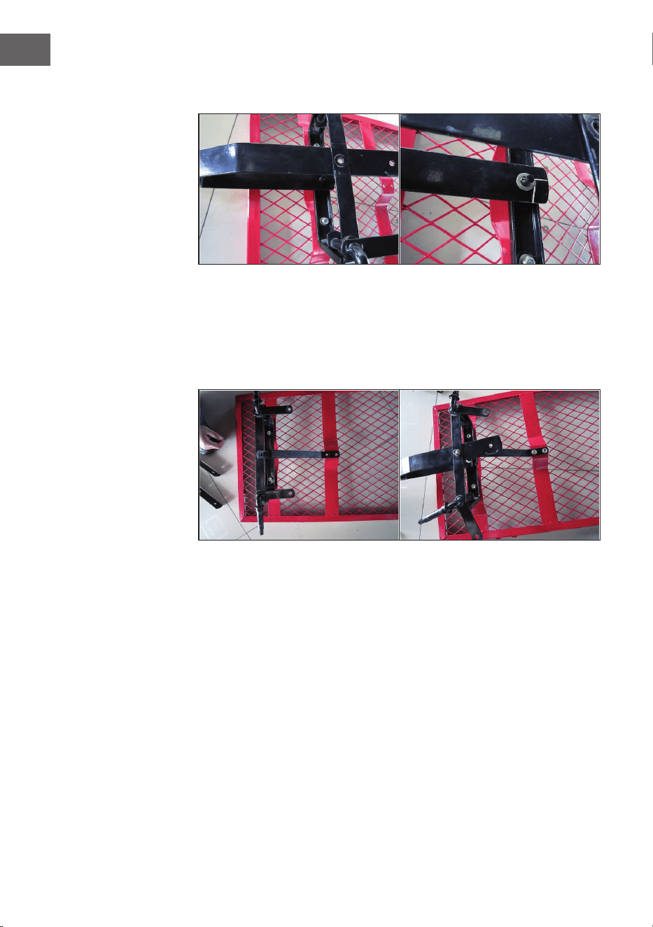
2. Setzen die Gabel (13) auf die vordere Achshalterung (10), indem Sie die
Schrauben der Gabel durch die Bohrungen der Achshalterung (10) führen.
3. Setzen Sie ein Ende der mittleren Achsführung (11) an den Boden (1)
und das andere Ende an die vordere Achshalterung (10). Richten Sie die
Bohrungen der vorderen Achshalterung (10), der mittleren Achsführung
(vorn) und der Gabel (13) aus und führen Sie von unten M8x25-Schrauben
hindurch. Legen Sie von oben Unterlegscheiben über die Gewinde der
Schraube (M8) und befestigen Sie darüber M8-Muttern (17). Montieren
Sie das andere Ende mit 2 Satz M8x18-Schrauben, M8-Untelegscheiben
und Muttern (16).
11
DE
4. Setzen Sie den Lenkanschluss (12) auf die vordere Achshalterung (10).
Richten Sie die Bohrungen aus und befestigen Sie die Komponenten mit 3
Satz M8x18-Schrauben, M8-Untelegscheiben und Muttern (16).
MONTAGE DER RÄDER
1. Setzen Sie die Räder (7) an die Enden der vorderen und hinteren
Achshalterung (10 und 8).
2. Unterlegscheiben und Kontermuttern (20) an die Enden der Räder setzen.
12
DE
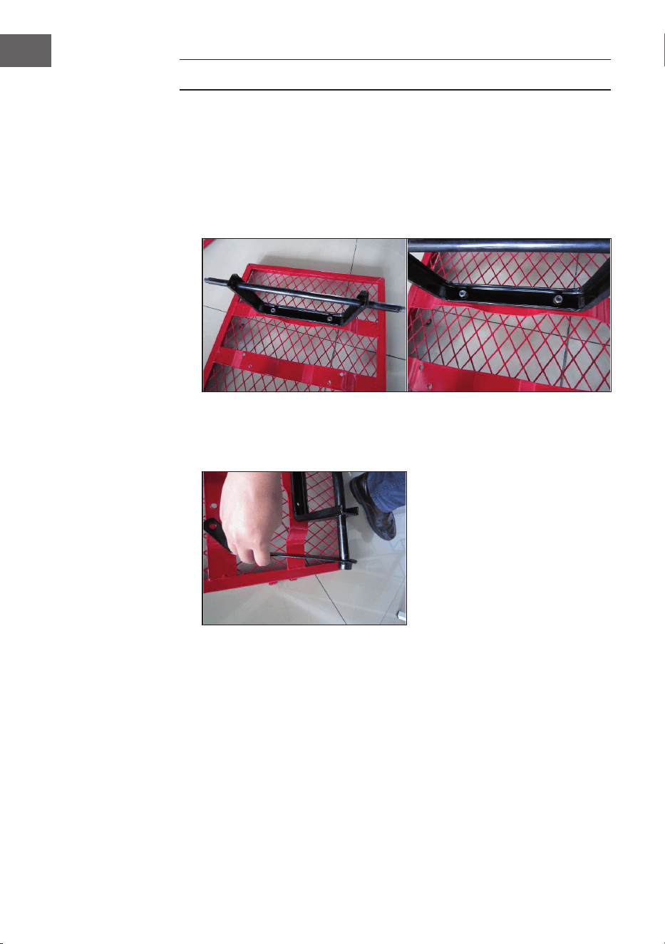
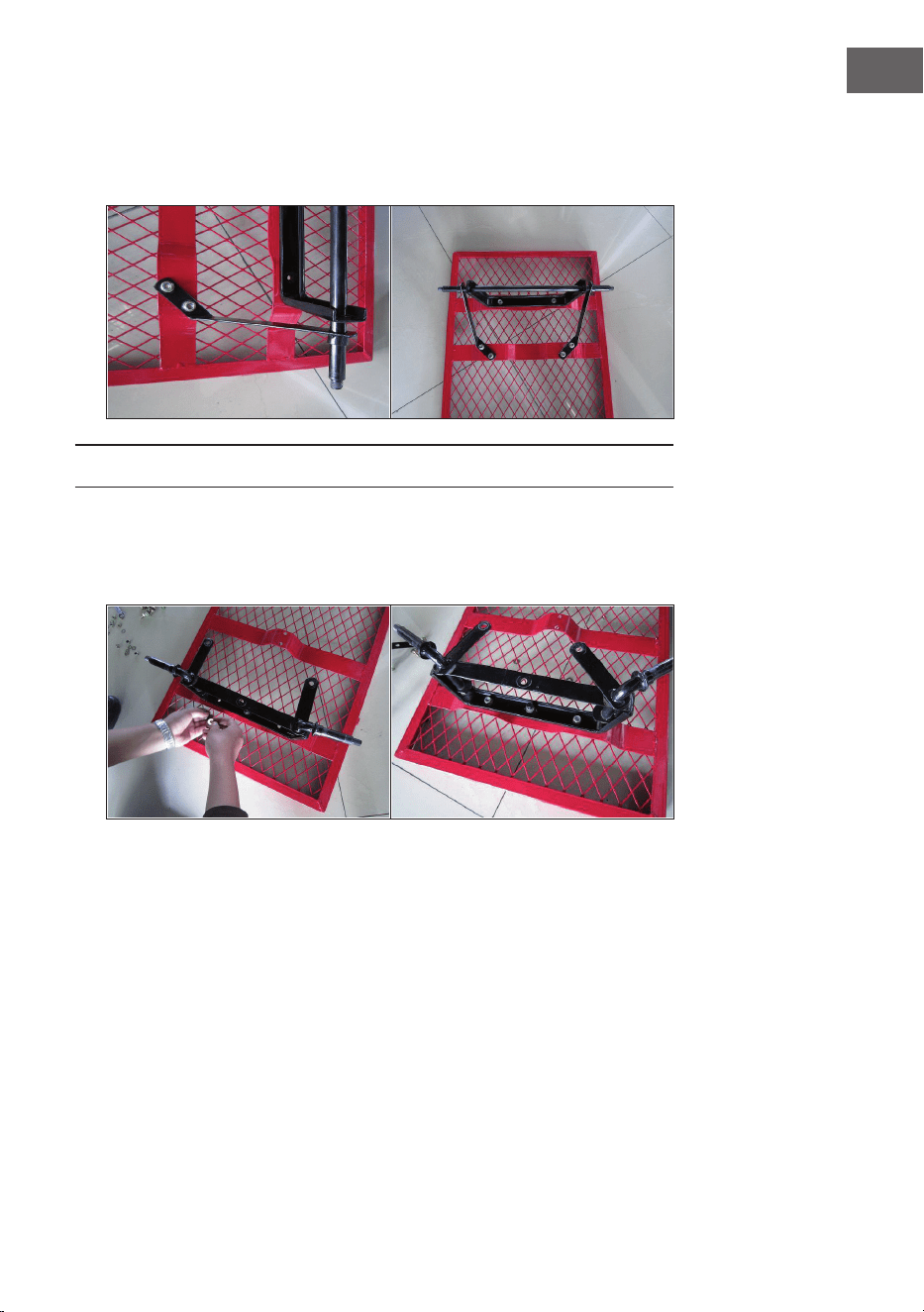
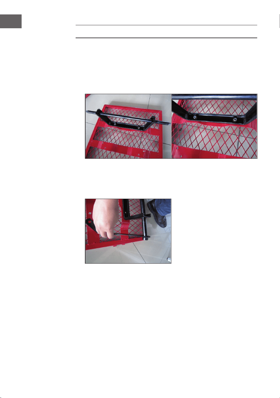
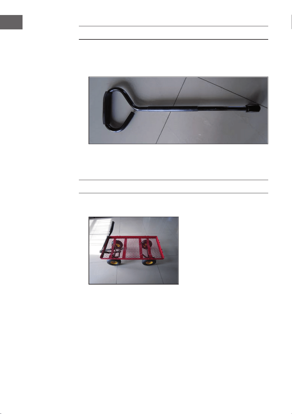
MONTAGE DES HANDZUGS
1. Entfernen Sie die Schrauben M8x60 und die Muttern (18) von dem
Kunststoffverbinder (14). Führen Sie das Ende des Zuggriffs (15) in den
Verbinder (14). Machen Sie Bohrungen im Zuggriff und dem Verbinder
zueinander bündig.
2. Setzen Sie den Zusammenbau von Zuggriff (15) und den Verbinder (14)
in die Gabel (13). Machen Sie die Bohrungen des Zuggriffs und dem
Verbinder bündig. Führen Sie durch die Bohrungen Schrauben des Typs
M8x60 und schrauben Sie sie mit Kontermuttern (18) fest.
MONTAGE DER WÄNDE
1. Stellen Sie den Wagen in eine aufrechte Position.
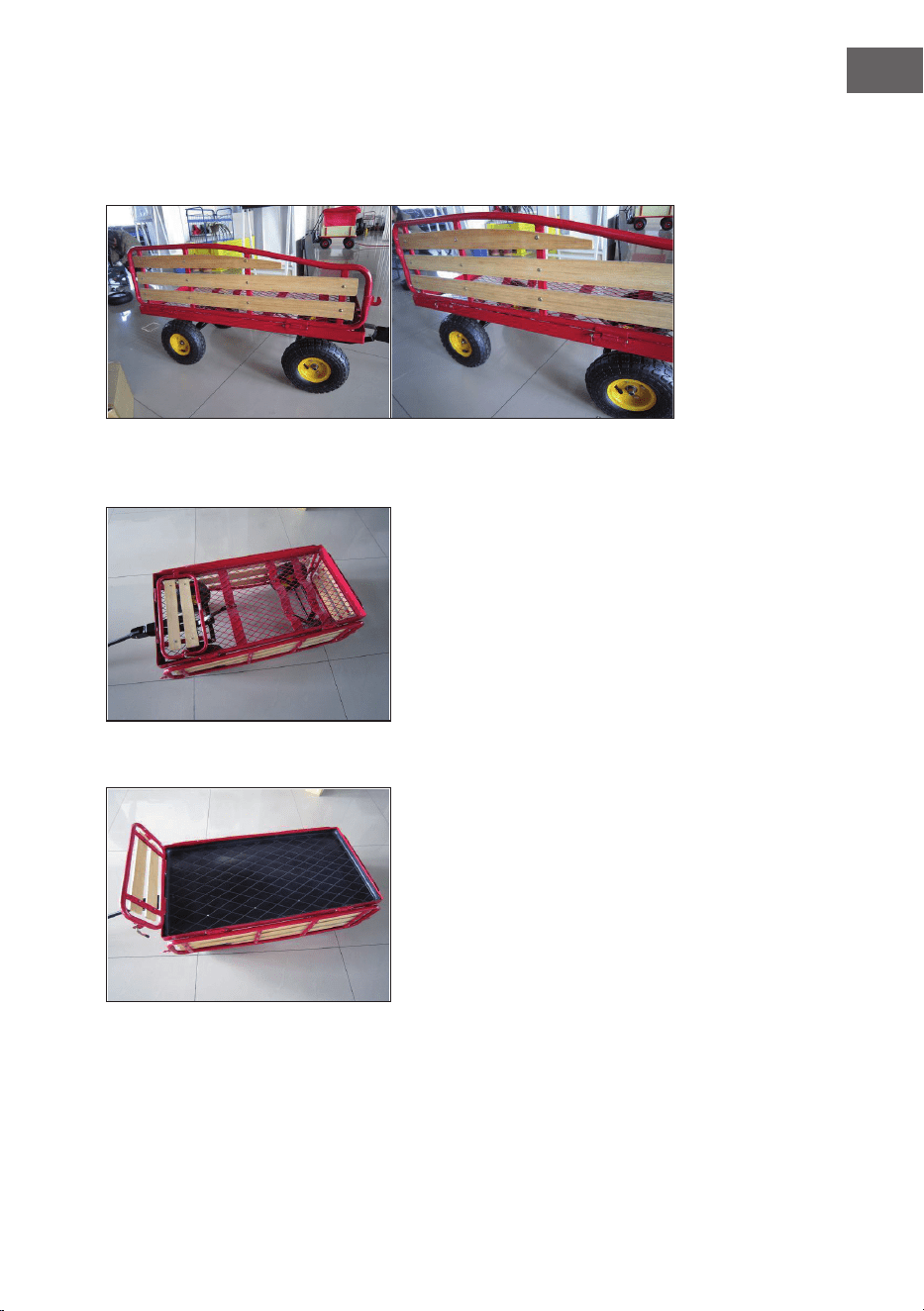
13
DE
2. Halten Sie die Löcher der rechten Seitenwand (3) mit den Bohrungen auf
der rechten Seite des Wagens bündig. Führen Sie einen Montagebolzen
(21) durch das zusammengeführte Loch und befestigen Sie einen Splint in
jedem Bolzen.
3. Wiederholen Sie den Schritt 2 für die linke Seitenwand (2), die
Vorderwand (4) und die Rückwand (5).
4. Setzen Sie die Kunststoffeinlage in den Boden.

14
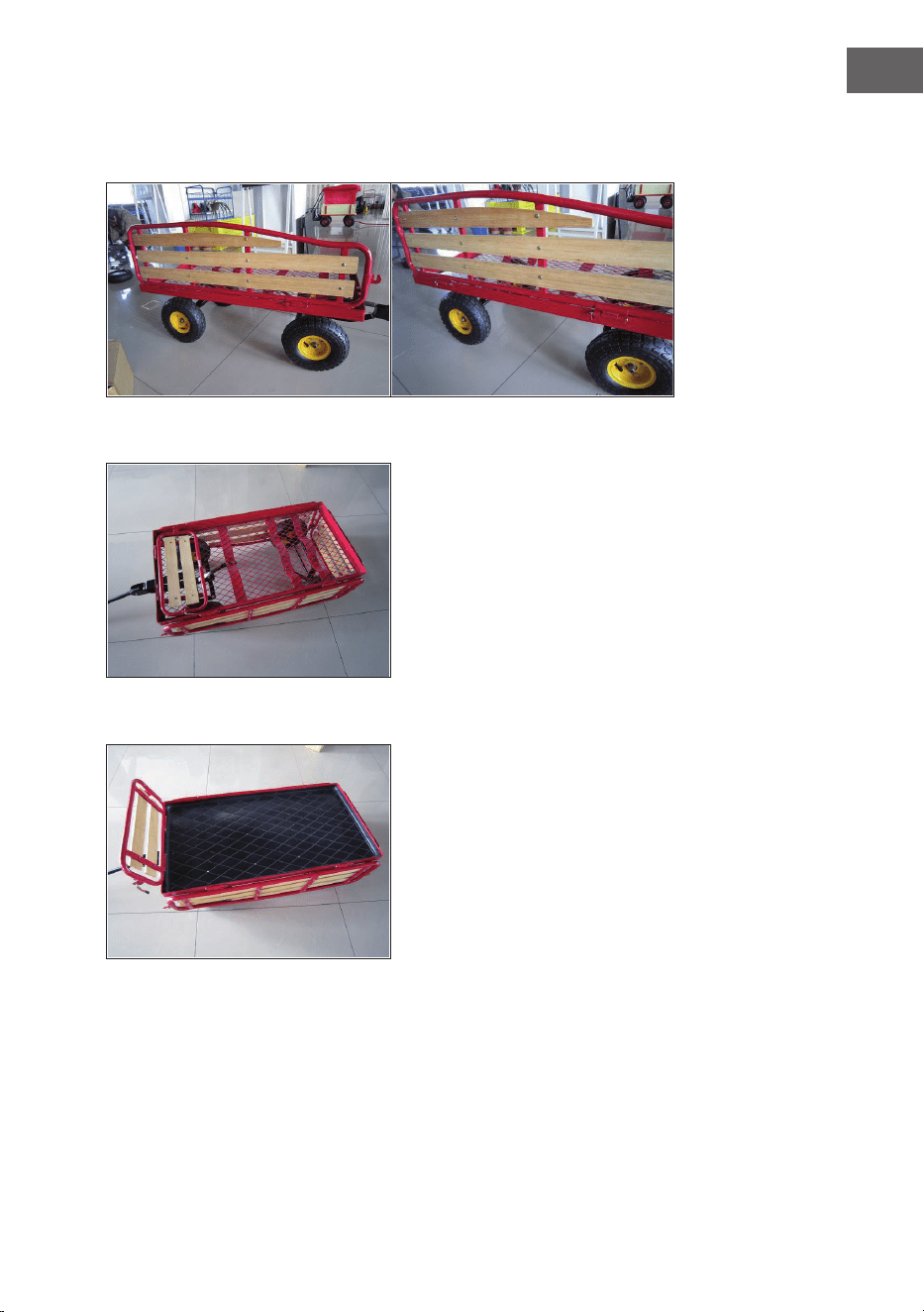
DE
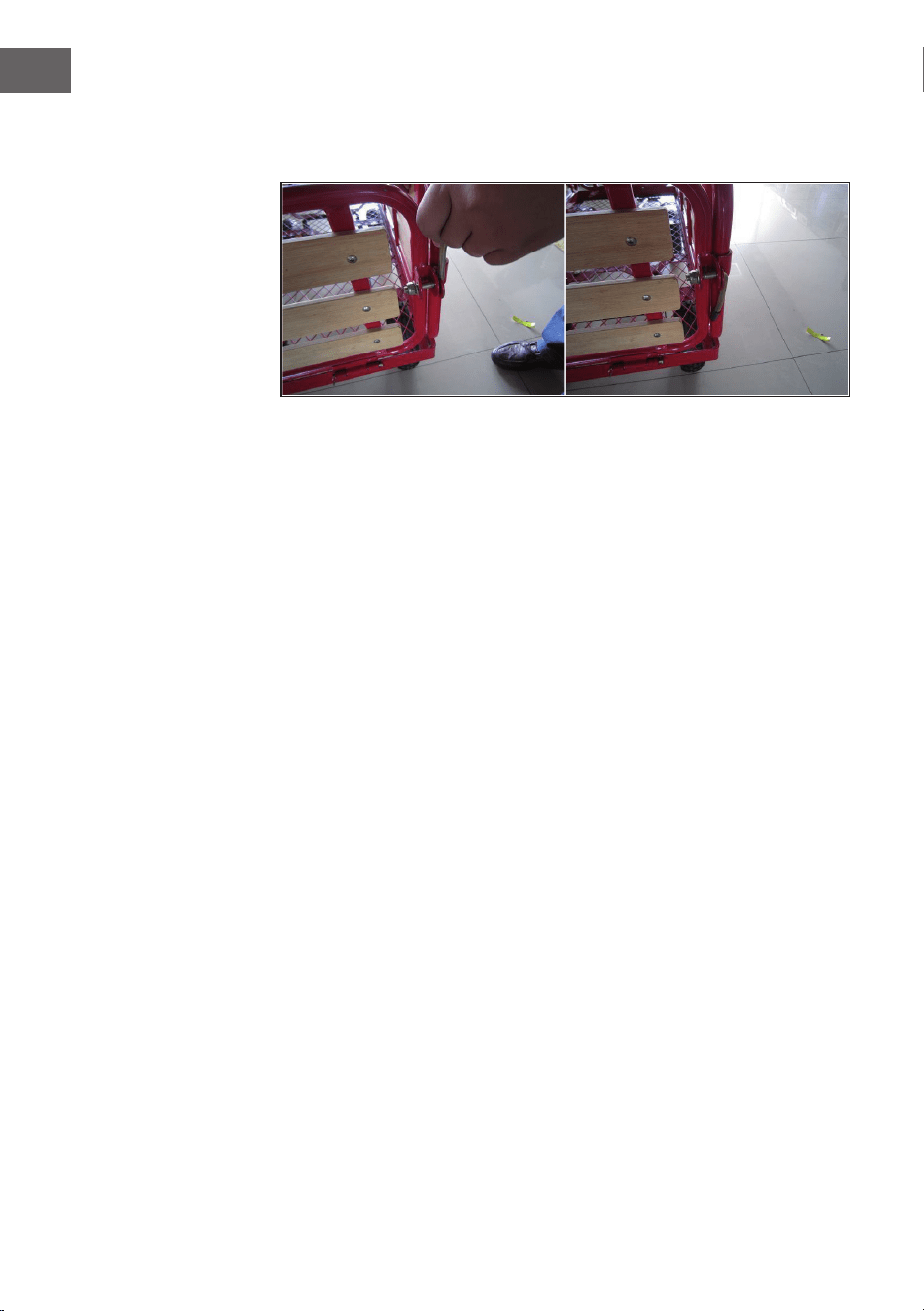
5. Klappen Sie die linke Wand (2) und die Rückwand (5) nach oben. Stellen
Sie den Verriegelungshebel an der Hinterwand nach oben, so dass er in die
Stange der Seitenwand greift.
6. Wiederholen Sie die Schritte für die verbleibenden Ecken des Wagens.

15
EN
Dear Customer,
Congratulations on purchasing this device. Please read
the following instructions carefully and follow them to
prevent possible damages. We assume no liability for
damage caused by disregard of the instructions and
improper use. Scan the QR code to get access to the
latest user manual and more product information.
CONTENTS
Parts List 16
Assembling the Rear Axle 20
Assembling the Front Axle 21
Mounting the Wheels 23
Assembly of the Hand Pull 24
Mounting the walls 24
MANUFACTURER & IMPORTER (UK)
Manufacturer:
Chal-Tec GmbH, Wallstrasse 16, 10179 Berlin, Germany.
Importer for Great Britain:
Berlin Brands Group UK Limited
PO Box 42
272 Kensington High Street
London, W8 6ND
United Kingdom

16
EN
PARTS LIST
No. Picture Desription Qty.
1
Bottom 1
2
Left side wall 1
3
Right side wall 1
4
Front wall 1
5
Back wall 1

17
EN
No. Picture Desription Qty.
6
Insert 1
7
Inlay 4
8
Wheel 1
9
Rear axle support 2
10
Rear axle guide 1
18
EN
No. Picture Desription Qty.
11
Middle axle guide front 1
12
Steering connection 1
13
Fork 1
14
Plastic connector 1
15
Pull handle 1

19
EN
No. Picture Desription Qty.
16
M8X18 screw
Washer
Nut
13
17
M8X25 Screw
Washer
Nut
1
18
M8X60 Screw
Washer
Nut
1
19
M11 Washer
Collar bolt
1
20
Washer M12
Lock nut
4
21
Wall mounting bolt
M7 washer
Cotter pin
4

20
EN
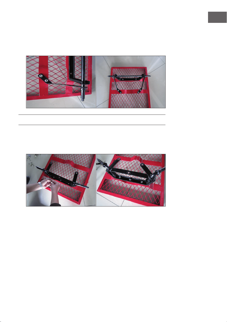
ASSEMBLING THE REAR AXLE
1. Placetheoor(1)upsidedown.2.
2. Place the rear axle holder (8) on the base (1). Make the drill holes of the
rearaxlebracket(8)ushwiththeholesontherearpartoftheoor(1).
Placescrews(16)throughtheushholesfrombelow.Installthewashers
(16) and nuts on the ends of the bolts. 3.
3. Place the left end of the rear axle guide (9) on the left side of the rear axle
bracket (8) with the welded spacer sleeves facing out. Repeat this step for
the right side.
21
EN
4. Aligntheholesontheatendsoftheleftsideoftherearaxleguide(9)
with the holes on the base (1). Insert the screws (16) from the bottom of
theoorintotheushalignedholes.Placeawasher(16)overthebolts
and screw a nut (16) on top of each.
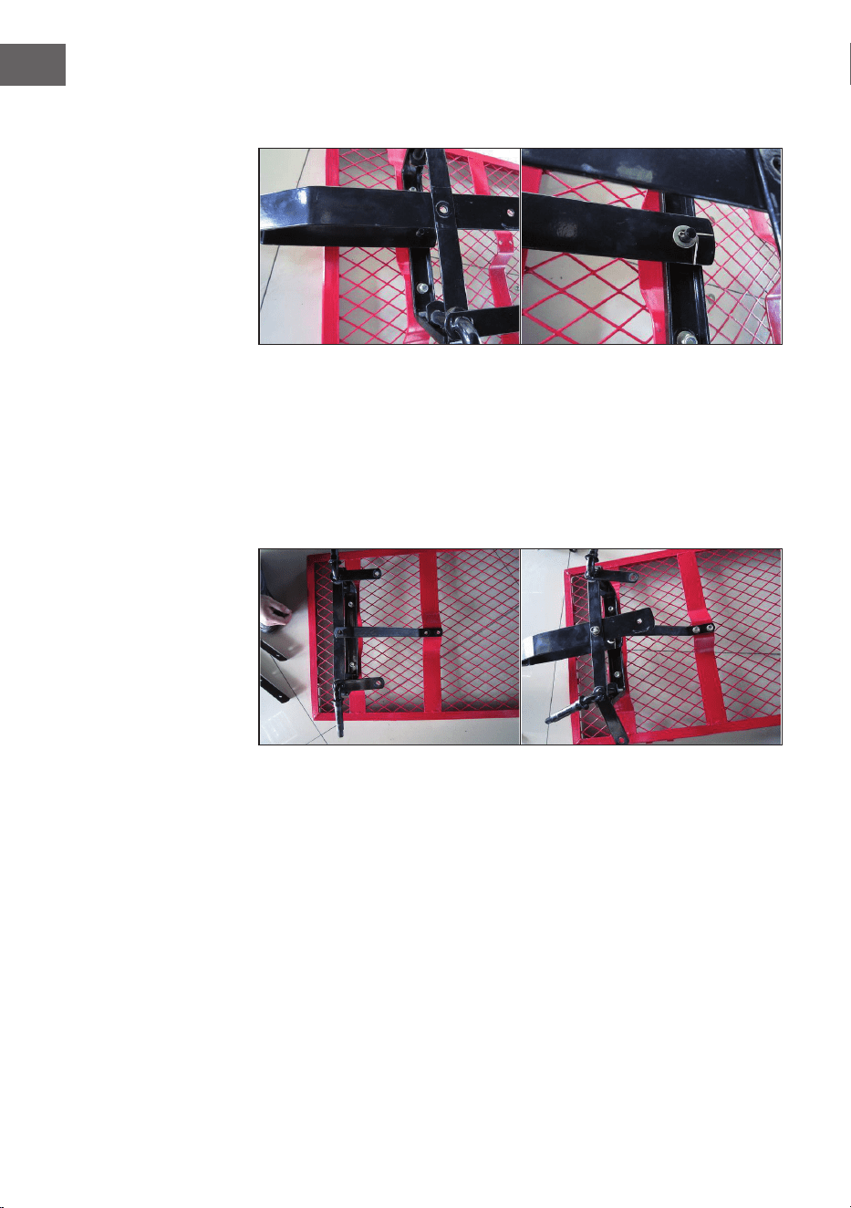
ASSEMBLING THE FRONT AXLE
1. Attachfrontaxlebracket(10)tofrontoor(1).Aligntheholes.Placea
washer (16) over the screws and screw a nut (16) onto each thread.

22
EN
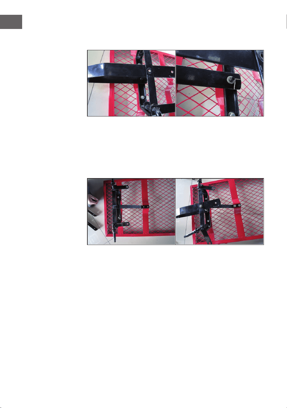
2. Place the fork (13) on the front axle bracket (10) by inserting the screws of
the fork through the holes of the axle bracket (10)
3. Placeoneendofthemiddleaxleguide(11)ontheoor(1)andtheother
end on the front axle bracket (10). Align the holes of the front axle bracket
(10), the middle axle guide (front) and the fork (13) and insert M8x25
screws through them from below. Place washers over the threads of the
screw (M8) from above and fasten M8 nuts (17) over them. Mount the
other end with 2 sets of M8x18 screws, M8 washers and nuts (16).

23
EN
4. Place the steering connector (12) on the front axle mount (10). Align the
holes and fasten the components with 3 sets of M8x18 bolts, M8 washers
and nuts (16).
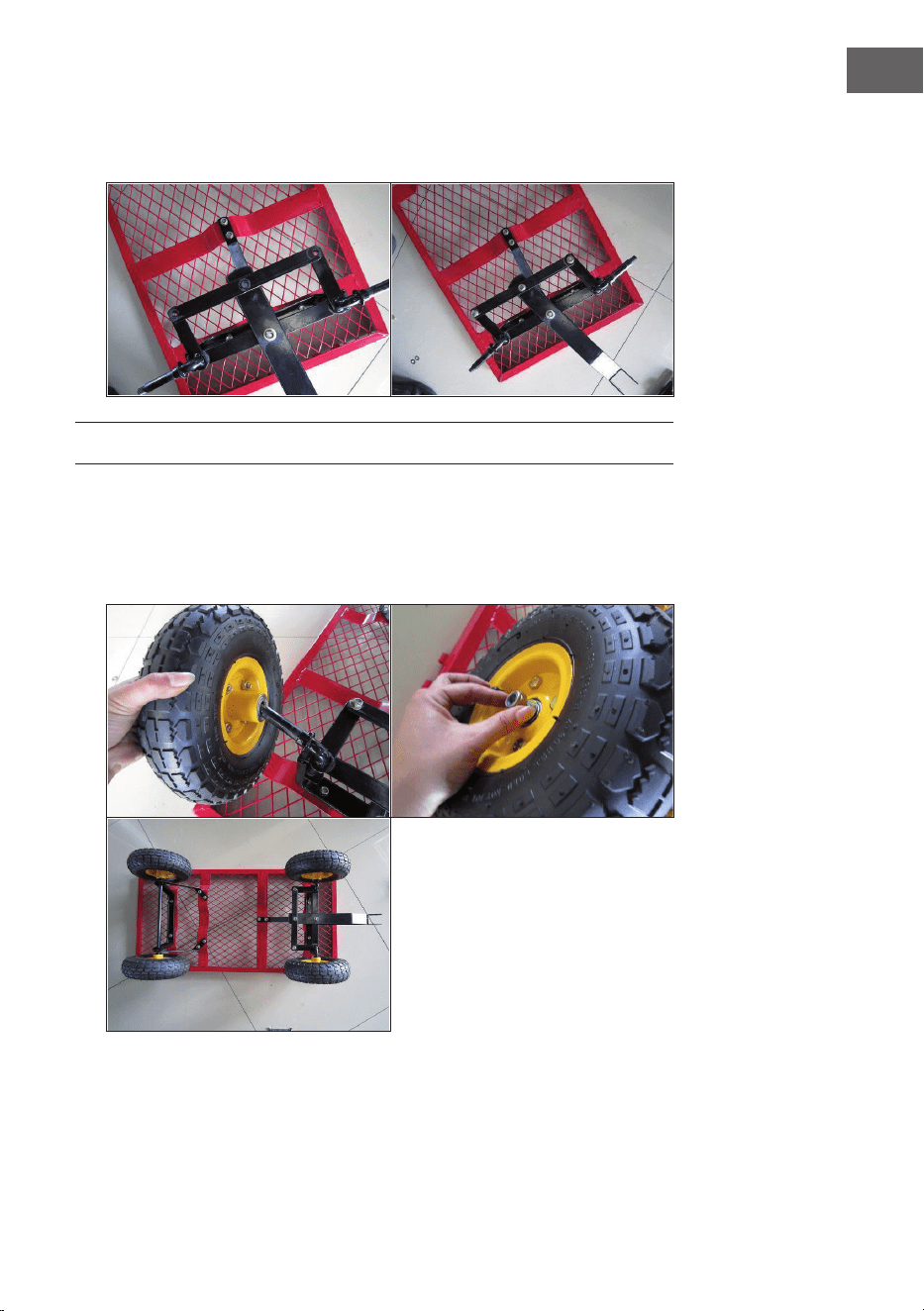
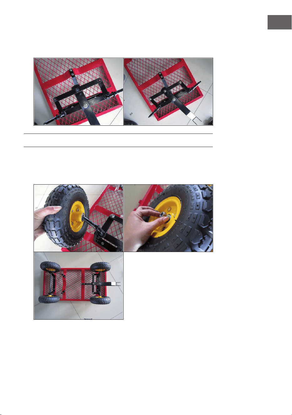
MOUNTING THE WHEELS
1. Place the wheels (7) on the ends of the front and rear axle brackets
(10 and 8).
2. Place washers and lock nuts (20) on the ends of the wheels.

24
EN
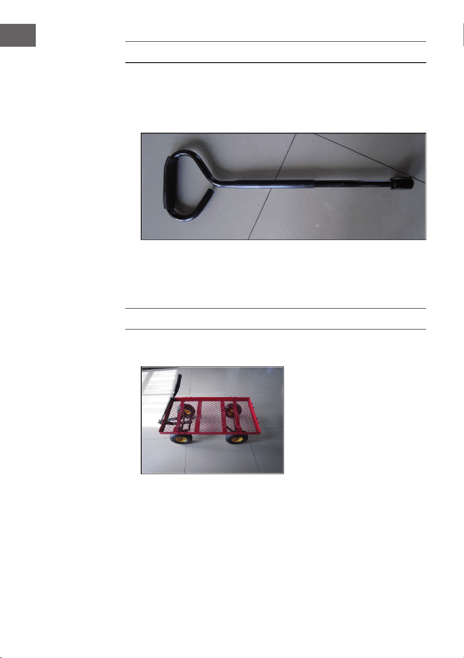
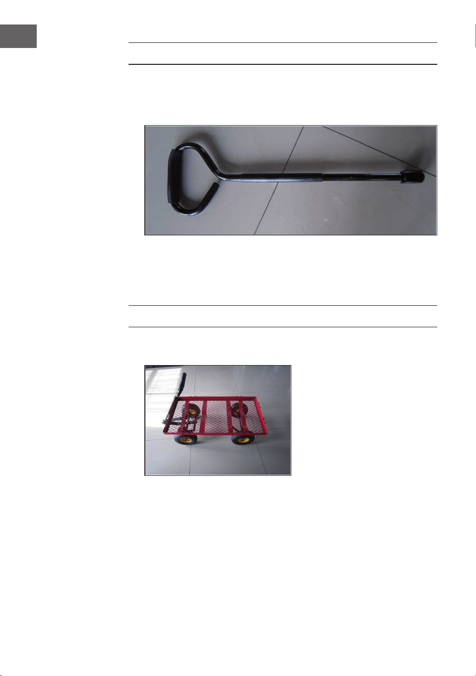
ASSEMBLY OF THE HAND PULL
1. Remove the M8x60 screws and the nuts (18) from the plastic connector
(14). Insert the end of the pull handle (15) into the connector (14). Make
holesinthepullhandleandtheconnectorushwitheachother.
2. Place the assembly of the handle (15) and the connector (14) into the fork
(13).Maketheholesinthepullhandleandtheconnectorushwitheach
other. Insert M8x60 screws through the holes and tighten them with lock
nuts (18).
MOUNTING THE WALLS
1. Place the carriage in an upright position.
25
EN
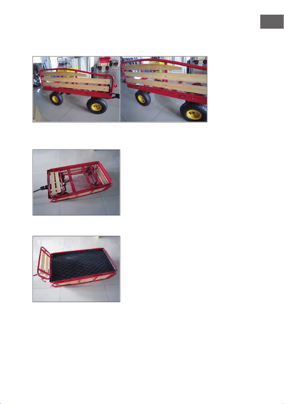
2. Keeptheholesoftherightsidepanel(3)ushwiththeholesontheright
side of the carriage. Insert a mounting bolt (21) through the merged hole
and secure a cotter pin in each bolt.
3. Repeat step 2 for the left side panel (2), front panel (4), and back panel (5).
4. Place the plastic insert in the base.

26
EN
5. Fold up the left wall (2) and the rear wall (5). Move the locking lever on the
rear wall upward so that it engages in the rod of the side wall.
6. Repeat the steps for the remaining corners of the carriage.

27
FR
Chère cliente, cher client,
Toutes nos félicitations pour l’acquisition de ce nouvel
appareil. Veuillez lire attentivement et respecter
les instructions de ce mode d’emploi an d’éviter
d’éventuels dommages. Nous ne saurions être tenus
pour responsables des dommages dus au non-respect
des consignes et à la mauvaise utilisation de l’appareil.
Scannez le QR-Code pour obtenir la dernière version
du mode d‘emploi et des informations supplémentaires
concernant le produit.
SOMMAIRE
Liste des pièces 28
Assemblage 32
Assemblage de l‘essieu avant 33
Montage des roues 35
Montage de la barre de traction 36
Montage des parois 36
FABRICANT ET IMPORTATEUR (UK)
Fabricant :
Chal-Tec GmbH, Wallstraße 16, 10179 Berlin, Allemagne.
Importateur pour la Grande-Bretagne :
Berlin Brands Group UK Limited
PO Box 42
272 Kensington High Street
London, W8 6ND
United Kingdom
28
FR
LISTE DES PIÈCES
N° Illustration Description Qtè.
1
Plancher 1
2
Paroi latérale gauche 1
3
Paroi latérale droite 1
4
Paroi avant 1
5
Fond intérieur 1

29
FR
N° Illustration Description Qtè.
6
Fond intérieur 1
7
Roue 4
8
Support d'essieu arrière 1
9
Guide d'essieu arrière 2
10
Support d‘essieu avant 1

30
FR
Nr. Illustration Description Qtè.
11
Guide d'essieu central à
l'avant
1
12
Raccordement à la
direction
1
13
Fourche 1
14
Raccord en plastique 1
15
Poignée de traction 1

31
FR
Nr. Illustration Description Qtè.
16
Vis M8X18
Rondelle
écrou
13
17
Vis M8X25
rondelle
écrou
1
18
Vis M8X60
rondelle
écrou
1
19
Rondelle M11
goupille fendue
1
20
Rondelle M12
Contre-écrou
4
21
Boulondexationpourles
parois
Rondelle M7
goupille
4
32
FR
ASSEMBLAGE
1. Posez le plancher (1) à l‘envers.
2. Placez le support d‘essieu arrière (8) sur le plancher (1). Alignez les trous
du support d‘essieu arrière (8) avec les trous à l‘arrière du plancher (1).
Insérezlesvis(16)parlebasàtraverslestrousafeurant.Fixezles
rondelles (16) et les écrous aux extrémités des vis.
.
3. Placez l‘extrémité gauche du guide d‘essieu arrière (9) sur le côté
gauche du support d‘essieu arrière (8) avec les entretoises soudées vers
l‘extérieur. Répétez cette étape pour le côté droit..
33
FR
4. Alignez les trous sur les extrémités plates du côté gauche du guide d‘essieu
arrière (9) avec les trous en bas (1). Insérez les vis (16) du dessous du
plancherdanslestrousafeurant.Placezunerondelle(16)etvissezun
écrou (16) sur chaque vis.
ASSEMBLAGE DE L‘ESSIEU AVANT
1. Fixez le support d‘essieu avant (10) au plancher à l‘avant (1). Alignez les
trous. Placez une rondelle (16) sur les vis et vissez un écrou (16) sur le
letage.

34
FR
2. Placez la fourche (13) sur le support d‘essieu avant (10) en passant les vis
de la fourche dans les trous du support d‘essieu (10).
3. Placez une extrémité du guide d‘essieu central (11) sur le plancher (1)
et l‘autre extrémité sur le support d‘essieu avant (10). Alignez les trous
du support d‘essieu avant (10), du guide d‘essieu central (avant) et de la
fourche (13) et insérez les vis M8x25 par le bas. Placez les rondelles sur les
letagesdelavis(M8)etxezlesécrousM8(17)dessus.Montezl‘autre
extrémité avec 2 jeux de vis M8x18, rondelles M8 et écrous (16).

35
FR
4. Placez le raccordement à la direction (12) sur le support d‘essieu avant
(10).Alignezlestrousetxezlesélémentsavec3jeuxdevisM8x18,
rondelles M8 et écrous (16).
MONTAGE DES ROUES
1. Placez les roues (7) aux extrémités des supports d‘essieu avant et arrière
(10 et 8).
2. Placez des rondelles et des contre-écrous (20) aux extrémités des roues.

36
FR
MONTAGE DE LA BARRE DE TRACTION
1. Retirez les vis et écrous M8x60 (18) du raccord en plastique (14). Insérez
l‘extrémité de la poignée de traction (15) dans le raccord (14). Faites des
trous dans la poignée de traction et le raccord au même niveau.
2. Placez l‘ensemble poignée de traction (15) et raccord (14) dans la fourche
(13).Faitesafeurerlestrousdelapoignéedetractionetduconnecteur.
InsérezlesvisM8x60danslestrousetxez-lesavecdescontre-écrous
(18).
MONTAGE DES PAROIS
1. Mettez le chariot à l‘endroit.

37
FR
2. Tenez les trous du panneau latéral droit (3) alignés avec les trous du côté
droitduchariot.Insérezunboulondexation(21)dansletrouetxezune
goupille fendue dans chaque boulon.
3. Répétez l‘étape 2 pour la paroi latérale gauche (2), la paroi avant (4) et la
paroi arrière (5).
4. Placez le fond en plastique sur le plancher du chariot.

38
FR
5. Rabattez la paroi gauche (2) et la paroi arrière (5). Soulevez le levier de
verrouillage de la paroi arrière pour qu‘il s‘engage dans la barre de la paroi
latérale.
6. Répétez les étapes pour les autres coins du chariot.

39
ES
Estimado cliente:
Le felicitamos por la adquisición de este producto. Lea
atentamente el siguiente manual y siga cuidadosamente
las instrucciones de uso con el n de evitar posibles
daños. La empresa no se responsabiliza de los daños
ocasionados por un uso indebido del producto o por
haber desatendido las indicaciones de seguridad.
Escanee el siguiente código QR para obtener acceso al
manual de usuario más reciente y otra información sobre
el producto.
ÍNDICE
Lista de piezas 40
Montaje 44
Montaje del eje frontal 45
Montaje de las ruedas 47
Montaje del tirador 48
Montaje de las partes laterales 48
FABRICANTE E IMPORTADOR (RU)
Fabricante:
Chal-Tec GmbH, Wallstraße 16, 10179 Berlín, Alemania.
Importador para el Reino Unido:
Berlin Brands Group UK Limited
PO Box 42
272 Kensington High Street
London, W8 6ND
United Kingdom

40
ES
LISTA DE PIEZAS
N° Imagen Descripción Cant.
1
Base 1
2
Parte lateral izquierda 1
3
Parte lateral derecha 1
4
Parte frontal 1
5
Parte posterior 1

41
ES
N° Imagen Descripción Cant.
6
Fondo 1
7
Rueda 4
8
Soporte del eje posterior 1
9
Guía del eje posterior 2
10
Soporte del eje frontal 1

42
ES
Nr. Imagen Descripción Cant.
11
Guía del eje central frontal 1
12
Conector de dirección 1
13
Yugo 1
14
Enganche de plástico 1
15
Tirador 1

43
ES
Nr. Imagen Descripción Cant.
16
Tornillo M8X18
Arandela
Tuerca
13
17
Tornillo M8X25
Arandela
Tuerca
1
18
Tornillo M8X60
Arandela
Tuerca
1
19
Arandela M11
Chaveta
1
20
ArandelaM12
Contratuerca
4
21
Perno de montaje para las
partes laterales
Arandela M7
Pasador de chaveta
4
44
ES
MONTAJE
1. Gire la base (1) al revés.
2. Coloqueelsoportedelejeposterior(8)sobrelabase(1).Alineelosoricios
enelsoportedelejeposterior(8)conlosoriciosenlaparteposteriorde
labase(1).Insertelostornillos(16)desdeabajoatravésdelosoricios
alineados. Enrosque las arandelas (16) y las tuercas en los tornillos.
3. Coloque el extremo izquierdo de la guía del eje posterior (9) en el lado
izquierdo del soporte del eje posterior (8) con los bujes espaciadores
soldados mirando hacia afuera. Repita este paso para montar el lado
derecho.

45
ES
4. Alineelosoriciosenelextremoplanodelladoizquierdodelaguíadeleje
posterior(9)conlosoriciosenlabase(1).Insertelostornillos(16)desde
abajodelabaseatravésdelosoriciosalineados.Enrosquelasarandelas
(16) y las tuercas (16).
MONTAJE DEL EJE FRONTAL
1. Coloque el soporte del eje frontal (10) sobre la parte frontal de la base (1).
Alineelosoricios.Enrosquelasarandelas(16)ylastuercas(16)enlos
tornillos.
46
ES
2. Coloque el yugo (13) sobre el soporte del eje frontal (10) pasando el
tornillodelyugoatravésdelosoriciosdelsoportedelejefrontal(10).
3. Posicione un extremo del guía del eje central (11) sobre la base (1) y el
otroextremosobreelsoportedelejefrontal(10).Alineelosoriciosdel
soporte del eje frontal (10), el guía del eje central (frontal) y el yugo (13) y
pase los tornillos M8x25 desde abajo. Enrosque las arandelas y las tuercas
M8 (17) en los tornillos M8. Monte el otro extremo con los 2 juegos de los
tornillos M8x18, arandelas M8 y tuercas (16).

47
ES
4. Coloque el conector de dirección (12) en el soporte del eje frontal (10).
Alineelosoriciosyjelaspartescon3juegosdetornillosM8x18,
arandelas M8 y tuercas (16).
MONTAJE DE LAS RUEDAS
1. Coloque las ruedas (7) en los extremos de los soportes del eje frontal y
posterior (10 y 8).
2. Fije las ruedas con las arandelas y contratuercas (20).
48
ES
MONTAJE DEL TIRADOR
1. Retire los tornillos M8x60 y las tuercas (18) del enganche de plástico (14).
Inserteunextremodeltirador(15)enelenganche(14).Alineelosoricios
del tirador con los del enganche.
2. Inserte el ensamblaje del tirador (15) y el enganche (14) en el yugo (13).
Alineelosoriciosdeltiradorconlosdelenganche.Inserteatravésdelos
oricioslostornillosM8x60yatorníllelosconlascontratuercas(18).
MONTAJE DE LAS PARTES LATERALES
1. Coloque el carro en posición recta.

49
ES
2. Alineelosoriciosenlapartelateralderecha(3)conlosoriciosenla
parte derecha del carro. Inserte el perno de montaje (21) a través del
oricioycoloqueunachavetaenlosextremosdecadapernodemontaje.
3. Repita el paso 2 para montar la parte lateral izquierda (2), la parte frontal
(4) y la parte posterior (5).
4. Inserte el fondo de plástico en la base.
50
ES
5. Levante la parte lateral izquierda (2) y la parte posterior (5). Mueva la
palanca de bloqueo de la parte posterior hacia arriba para que se enganche
en la barra de la parte lateral.
6. Repita el paso anterior para las esquinas restantes del carro.

51
IT
Gentile Cliente,
La ringraziamo per aver acquistato il dispositivo. La
preghiamo di leggere attentamente le seguenti istruzioni
per l’uso e di seguirle per evitare possibili danni tecnici.
Non ci assumiamo alcuna responsabilità per danni
scaturiti da una mancata osservazione delle avvertenze
di sicurezza e da un uso improprio del dispositivo.
Scansionare il codice QR seguente, per accedere al
manuale d’uso più attuale e per ricevere informazioni sul
prodotto.
INDICE
Lista dei componenti 52
Montaggio 56
Assemblare l’asse anteriore 57
Montare le ruote 59
Montaggio dell’impugnatura di traino 60
Montaggio delle pareti 60
PRODUTTORE E IMPORTATORE (UK)
Produttore:
Chal-Tec GmbH, Wallstraße 16, 10179 Berlino, Germania.
Importatore per la Gran Bretagna:
Berlin Brands Group UK Limited
PO Box 42
272 Kensington High Street
London, W8 6ND
United Kingdom

52
IT
LISTA DEI COMPONENTI
N° Immagine Descrizione Qtà.
1
Fondo 1
2
Parete laterale sinistre 1
3
Parete laterale destra 1
4
Parete frontale 1
5
Parete posteriore 1
53
IT
N° Immagine Descrizione Qtà.
6
Inserto per il fondo 1
7
Ruota 4
8
Supporto asse posteriore 1
9
Guida asse posteriore 2
10
Supporto asse anteriore 1

54
IT
Nr. Immagine Descrizione Qtà.
11
Guida asse centrale
anteriore
1
12
Collegamento di sterzatura 1
13
Forcella 1
14
Connettore di plastica 1
15
Impugnatura di traino 1

55
IT
Nr. Immagine Descrizione Qtà.
16
Vite M8x18 + rondella +
dado
13
17
Vite M8x25 + rondella +
dado
1
18
Vite M8x60 + rondella +
dado
1
19
Rondella M11 e bullone
angiato
1
20
Rondella M12 +
controdado
4
21
Bullone di montaggio per
la parete + rondella M7 +
connettore elastico
4

56
IT
MONTAGGIO
1. Poggiare il fondo (1) al contrario.
2. Posizionare il supporto dell’asse posteriore (8) sul fondo (1). Mettere in
corrispondenza i fori del supporto dell’asse posteriore (8) con i fori della
parte posteriore del fondo (1). Inserire dal basso le viti (16) attraverso i fori
in corrispondenza. Posizionare rondelle (16) e dadi sulle estremità delle
viti.
3. Posizionare l’estremità sinistra della guida dell’asse posteriore (9) sul lato
sinistro del supporto dell’asse posteriore (8) con i distanziatori saldati
verso l’esterno. Ripetere la procedura per il lato destro.

57
IT
4. Mettere in corrispondenza i fori sulle estremità piatte del lato sinistro
della guida dell’asse posteriore (9) con i fori sul fondo (1). Inserire le viti
(16) dal lato inferiore del fondo nei fori in corrispondenza. Mettere una
rondella (16) sulle viti e avvitare un dado (16) sopra a ognuna.
ASSEMBLARE L’ASSE ANTERIORE
1. Montare il supporto dell’asse anteriore (10) sulla parte anteriore del fondo
(1). Mettere in corrispondenza i fori. Mettere una rondella (16) sulle viti e
avvitare un dado (16) sopra a ognuna.
58
IT
2. Posizionare la forcella (13) sul supporto dell’asse anteriore (10), facendo
passare le viti della forcella attraverso i fori sul supporto dell’asse (10).
3. Mettere un’estremità della guida dell’asse centrale (11) sul fondo (1)
e l’altra estremità sul supporto dell’asse anteriore (10). Mettere in
corrispondenza i fori sul supporto dell’asse anteriore (10), sulla guida
dell’asse centrale (anteriore) e sulla forcella (13) e farci passare attraverso
levitiM8x25.Metterelerondelledall’altosullalettaturadelleviti(M8)
essarcisopradadiM8(17).Montarel’altraestremitàcon2setdiviti
M8x18, rondelle M8 e dadi (16).
59
IT
4. Posizionare il collegamento di sterzatura (12) sul supporto dell’asse
anteriore(10).Mettereincorrispondenzaiforiessareicomponenticon
3 set di viti M8x18, rondelle M8 e dadi (16).
MONTARE LE RUOTE
1. Posizionare le ruote (7) alle estremità dei supporti dell’asse anteriore e
posteriore (10 e 8).
2. Mettere rondelle e controdadi (20) alle estremità delle ruote.
60
IT
MONTAGGIO DELL’IMPUGNATURA DI TRAINO
1. Togliere le viti M8x60 e i dadi (18) dal connettore di plastica (14). Far
passare l’estremità dell’impugnatura di traino (15) nel connettore (14).
Mettere in corrispondenza i fori sull’impugnatura e sul connettore.
2. Posizionare impugnatura (15) e connettore (14) assemblati nella forcella
(13). Mettere in corrispondenza i fori sull’impugnatura e sul connettore.
Far passare nei fori viti M8x60 e stringere saldamente con i controdadi
(18).
MONTAGGIO DELLE PARETI
1. Mettere il carrello in posizione standard.
61
IT
2. Assicurarsi che i fori sulla parete destra (3) siano in corrispondenza dei fori
sul lato sinistro del carrello. Far passare un bullone di montaggio (21) nei
foriessareunacopigliainognibullone.
3. Ripetere il passaggio 2 per la parete sinistra (4), quella anteriore (4) e
quella posteriore (5).
4. Posizionare l’inserto in plastica sul fondo.

62
IT
5. Piegare verso l’alto la parete sinistra (2) e quella posteriore (5). Muovere
verso l’alto la leva di bloccaggio sulla parete posteriore, in modo che l’asta
si incastri nella parete laterale
6. Ripetere i passaggi per gli angoli del carrello rimanenti.