
INSTRUCTIONS
FOR USE
BLAST-CHILLER
“NEW RUNNER” Series
FULL TOUCH Control Panel
BCT/05 US
BCT/10 US
BCT/15 US
Manual BCT US - Rev. 03-2026
INSTRUCTIONS
FOR USE
BLAST-CHILLER
“NEW RUNNER” Series
FULL TOUCH Control Panel
BCT/05 US
BCT/10 US
BCT/15 US
Manual BCT US - Rev. 03-2026
www.gemm-srl.com

The manufacturer reserves the right to make improvements to the equipment or accessories at any time without notice.
Partial reproduction without the consent of the Manufacturer is forbidden. The measurements provided are indicative and not binding.
The original drafting language is Italian: the manufacturer is not responsible for any translation/interpretation errors.
Explaining the pictograms
The installation and use instructions are valid for all models unless otherwise specified by the following pictograms:
Danger! Immediate danger situation or
dangerous situation that could cause injury or
death.
Read the instruction manual
Reference to another chapter
Earthing symbol
In-depth chapter or text
Equipotential symbol
Hot surfaces, danger of burns
Dear Installer/Customer
This booklet contains all the information necessary for a safe and correct installation and use of the equip-
ment: We therefore recommend that you read it carefully before performing any operation and keep it
carefully for future reference.
If there is need for further information or if some part of the booklet has not been understood, we remain
available to answer all your questions.
Good luck with your job!
CONTENTS
Service
Service
INSTALLATION
Safety warnings....................................................................................................................................... page 4
Technical data .......................................................................................................................................... page 10
Transport, unpacking and checking ................................................................................................ page 14
Installation ................................................................................................................................................ page 16
Final checks .............................................................................................................................................. page 20
Service
USE
Safety warnings....................................................................................................................................... page 4
Preliminary knowledge ........................................................................................................................ page 22
Use ............................................................................................................................................................... page 26
Ordinary maintenance ......................................................................................................................... page 42
After-sales service .................................................................................................................................. page 46
Warranty and service ............................................................................................................................ page 46
4
Failure to comply with the following standards may cause damage and even fatal
injuries, void the warranty and release the Manufacturer from all liability. Before
installation, use and maintenance of the equipment, read this booklet carefully and
keep it carefully for any further future consultation by the various operators. If you
have not understood all the contents of this booklet, contact the Manufacturer. In case
of loss or deterioration of the documentation, ask the Manufacturer for a replacement.
Who should read this manual
This manual is intended for both the operator and the technicians authorized to install and maintain the
equipment. Operators must not carry out operations reserved for maintenance workers or specialized
technicians. The manufacturer is not liable for any damages resulting from the failure to comply with this
prohibition.
Service
Specialized forklift operator: specialized operator, in charge of handling the equipment
and equipped with a license for the use of forklifts.
Service
Specialized electrician: specialized electrician who has attended the manufacturer's quali-
fication courses that allow him any intervention on the equipment. The specialized electri-
cian must be able to install the equipment and run it under normal conditions, is qualified for
all electrical and mechanical adjustment interventions, maintenance and repair. He can op-
erate in the presence of voltage inside electrical cabinets and junction boxes.
Service
Operator charged with the use of the equipment: specialized personnel capable of oper-
ating the equipment in normal conditions using the relevant controls. He must also be able
to perform simple routine maintenance operations (cleaning, loading the product), starting
or restoring the equipment following a possible forced stop.
Using and storing the manual
• This manual aims to provide all the necessary information so that, in addition to using the equipment
correctly, it is possible to manage it in the most autonomous and safe way possible.
• The manual is divided into chapters and paragraphs: therefore the index page provides an easy way to
find any aspect of interest.
• The material contained in this document is provided for information’s sake only and is subject to change
without notice. Despite the utmost attention paid to the drafting of the document, the manufacturer
is not responsible for damage resulting from errors or omissions and from the use of the information
contained herein or from incorrect translations.
• Keep this manual, and all the attached documentation, in good condition, legible and complete with
all its parts; keep it near the equipment, in a place accessible and known to all operators. If some parts
are not understood, contact the Manufacturer.
• In case of transfer of the equipment, let the new user have this booklet.
• Keep clear of obstruction all ventilation openings in the appliance enclosure or in the structure for
building-in.
Safety warnings
1
5
Warnings for the forklift driver
All transport operations must be carried out only by qualied personnel authorized
by the Manufacturer, according to the standards in force in the country of use,
complying with the rules relating to systems and safety at work.
The driver must operate in perfect psychophysical conditions, must verify that the individual
accident prevention devices are intact and fully functional and that there are no adverse con-
ditions that can make handling dicult. The sta involved in these operations must NOT wear
rings, watches, jewellery, unfastened or loose clothing, such as ties, torn clothing, scarves, unbut
-
toned jackets or shirts with open zips etc ... In general, sta must use accident prevention garments.
Handling other than that indicated in this booklet can cause injury or fatal accidents to the
driver and damage to the equipment and structures of the installation site.
For the entire duration of the transport, the equipment must be kept upright on its pallet,
wrapped in cardboard: this packaging must be secured to the means of transport with suit-
able tools (e.g. ropes) to prevent it from overturning or moving during handling. Never turn
the equipment upside down or place it horizontally.
During the transport phase, the ambient temperature must never drop below 4°C/ 39,2°F.
All handling and lifting operations must be carried out with the utmost caution, checking
that all personnel are strictly at a safe distance, and that no one stands under suspended,
stationary or moving loads.
Before starting the operation, check the entire area of movement of the equipment, in or-
der to detect the possible presence of dangerous points.
Always make sure that the forklift has a capacity greater than the weight of the equipment to be
lifted: the operator of the forklift will be responsible for lifting the load. The use of unsuitable
equipment can lead to accidents to personnel carrying out the operation and/or damage to
the equipment.
The manufacturer accepts no responsibility for the improper and non-compliant use of lifting,
transporting and handling devices.
• Depending on the type, size and weight, suitable packaging has been used to ensure integrity and
preservation during transport up to the delivery to the buyer, for this reason do not remove it before or
during transport.
• The equipment contains an airtight refrigeration circuit that contains flammable gas. For this reason,
during transport, take care not to damage any component of the cooling circuit itself. In the event of
damage, avoid naked flames or ignition sources, disconnect the appliance from the power supply, ven
-
tilate the room for a few minutes and notify technical service.
Service

6
Warnings for the installer
Before installing the equipment, read this manual carefully and scrupulously
follow the instructions provided.
All installation and extraordinary maintenance operations must be carried out only by
qualied personnel authorized by the Manufacturer, in compliance with the standards in force
in the country of use and to the rules relating to systems and safety at work.
The installer must operate in perfect psychophysical conditions, must verify that the individual
accident prevention devices are intact and fully functional and that there are no adverse
conditions that can make handling dicult.
Installation or maintenance other than that indicated in this booklet can cause injury or
fatal accidents to the installer and user and damage to the equipment and structures of the
installation site.
• During the installation of the equipment, the transit or stay of unauthorized persons near the work area
is prohibited.
• Before installing the equipment, check the compliance of the systems with the regulations in force in
the country of use and with what is indicated on the technical data plate.
• The equipment must be disconnected from the power supply before performing any installation or
maintenance work.
• The deactivation of the protective devices must be carried out only by authorized personnel, who will
ensure the safety of people and avoid any damage to the machine. After performing the necessary
maintenance, the protective devices must be reactivated correctly.
• During maintenance or repair operations, unauthorized persons must keep far from the equipment.
• At the end of the maintenance or repair operations, it is possible to restart the equipment only after the
specialized technician has ascertained that:
- the works have been carried out completely;
- the safety systems are active;
- the equipment works perfectly;
- nobody is operating the equipment.
• The replacement of the power supply cable must be carried out only by a qualified and authorized
technician. The cable can only be replaced with one of similar characteristics: the type of cable to be
used and its section is always indicated on the technical data plate. The grounding cable must always
be yellow-green.
• With the appliance installed, the electric cable and the power outlet must be easily accessible.
• Interventions, tampering or modifications not expressly authorized that do not comply with the
contents of this manual will void the warranty.
• The data plate provides important technical information: it is indispensable in case of a request for main-
tenance or repair of the equipment: we therefore advise you not to remove it, damage it or modify it.
• As potentially dangerous, the packaging material must be kept out of the reach of children or animals
and properly disposed of according to local regulations.
Service

7
Warnings for the user
Before the use and routine maintenance of the equipment, read this booklet
carefully and keep it with care for any further future consultation by the various
operators.
Any unauthorized tampering or replacement of one or more parts or components of the
equipment, the use of accessories and consumables other than the originals, can be an ac-
cident risk and release the manufacturer from any civil or criminal liability. In case of doubts
about the operation or the state of the equipment, do not use it and contact the manufacturer.
DANGER OF FROSTBITE: During its work phases, the equipment can manage very low tem-
peratures, avoid direct contact with the internal parts of the machine immediately after
opening the door.
Intended use
• This appliance is capable of rapidly lowering the core temperature of food.
• Any other use is improper and potentially dangerous.
• Do not store various objects, live animals, exposed liquids, corrosive or explosive substances such as
spray cans with flammable substances in this appliance. This appliance is not suitable for storing and
cooling medicines, plasma, laboratory preparations, substances and similar products indicated in the
directive on medical devices. The Manufacturer is not liable for any damage caused by use other than
that intended or by incorrect settings.
• The blast chiller must not be used:
- for uses other than those stated in this chapter;
- with faulty safety systems;
- after an incorrect installation;
- by untrained personnel;
- with maintenance work not performed or performed incorrectly;
- with the use of non-original spare parts;
- with damaged power supply cable and/or plug;
- with blocked ventilation ducts;
- with the product to be processed placed close to the ventilation grilles, any ventilation ducts, or on
the bottom of the cell.
• Do not store explosive substances, such as spray cans with flammable propellant in this appliance.
Maintenance and cleaning
• Any use, cleaning and maintenance other than those indicated in this booklet are considered improper
and can cause damage, injury or fatal accidents, void the warranty and release the Manufacturer from all
liability. Cleaning and maintenance performed by the user must not be carried out by children without
supervision.
• In the event of a move, keep the appliance upright.
• To speed up the cleaning process, do not use mechanical devices or means other than those
recommended by the manufacturer.
• The ordinary and extraordinary maintenance operations that require the opening of the electrical
panel or even partial dismantling of the blast chiller must be carried out only by qualified personnel
authorized by the Manufacturer.
Service

8
Operating anomalies
• If the equipment does not work or you notice functional or structural anomalies, disconnect it from
the electrical and water supply and contact a Service Centre authorized by the Manufacturer without
attempting to repair it yourself. For any repairs, request the use of original spare parts. Failure to comply
with this prescription will void the Warranty.
• To make sure that the appliance is in perfect conditions of use and safety, we recommend that you have
it serviced and checked at least once a year by an authorized service centre.
Use
• The start-up and use of the equipment must be entrusted only to trained personnel. The behaviour of the
operating personnel must in any case scrupulously comply with the accident prevention regulations in
force in the country where the appliance is used.
• The user must know the position and functions of all the control devices and characteristics of the blast
chiller.
• At the time of installation, all operating personnel must be properly trained on the risks of accidents,
safety devices, general accident prevention regulations provided for by international directives and by
the law in force in the country where the appliance is used.
• The appliance can be used by children under 8 years of age and by people with reduced physical,
sensory or mental abilities, or without experience or necessary knowledge, provided that they are
under surveillance or after they have received instructions relating to the safe use of the appliance and
to the understanding of the inherent dangers. Children must not play with the appliance.
• It is advisable to monitor the equipment throughout its operation.
• In order to obtain the best performance from the equipment, the following indications must be
complied with:
- avoid keeping the door open for a long time; if it has been opened, wait a few moments before
reopening it;
- pack or protect food, especially if it contains flavourings or spices;
- do not obstruct the front and/or rear ventilation ducts of the equipment; do not place the product
to be processed close to the ventilation grilles, the ventilation ducts, or directly on the bottom of the
cell;
- arrange the food evenly, starting from the bottom upwards; vice versa, remove the food starting from
the top down. The maximum load (evenly distributed) per tray or grille is equal to 40 kg;
- use only accessories recommended by the manufacturer.
• The data plate provides important technical information: it is indispensable in case of a request for
maintenance or repair of the equipment: we therefore advise you not to remove it, damage it or modify it.
• The refrigeration equipment has been built and designed with the appropriate precautions in order
to guarantee the health and safety of the user and does not have dangerous edges, sharp surfaces or
elements protruding from the overall dimensions. Its stability is guaranteed even with the door open,
however it is forbidden to hang on it.
- In the event of a fire, do not use water, take a CO
2
(carbon dioxide) extinguisher and cool the area of the
engine compartment down as quickly as possible.

9
Service
Service
Explaining the pictograms ................................................................................................................................................................ 2
Safety warnings ..................................................................................................................... 4
Who should read this manual .....................................................................................................................................................................4
Using and storing the manual .................................................................................................................................................................... 4
Warnings for the forklift driver ........................................................................................................................................................ 5
Warnings for the installer ...................................................................................................................................................................6
Warnings for the user ...........................................................................................................................................................................7
Intended use ..........................................................................................................................................................................................................7
Maintenance and cleaning ........................................................................................................................................................................... 7
Operating anomalies ........................................................................................................................................................................................ 8
Use ...............................................................................................................................................................................................................................8
Technical data ........................................................................................................................ 10
Installation diagram .............................................................................................................. 11
BCT/05 US ....................................................................................................................................................................................................11
BCT/10 US ....................................................................................................................................................................................................12
BCT/15 US ....................................................................................................................................................................................................13
Transport, unpacking and checking .................................................................................. 14
Transport ......................................................................................................................................................................................................14
Unpacking ................................................................................................................................................................................................... 14
Checking the appliance ...................................................................................................................................................................... 15
Handling after unpacking ..................................................................................................................................................................15
Installation .............................................................................................................................. 16
Choosing the position .........................................................................................................................................................................16
Electrical connection ............................................................................................................................................................................ 17
Connection to the waste water network ................................................................................................................................. 19
Final checks............................................................................................................................. 20
Final checks ............................................................................................................................................................. 20
INSTALLATION
10
Service
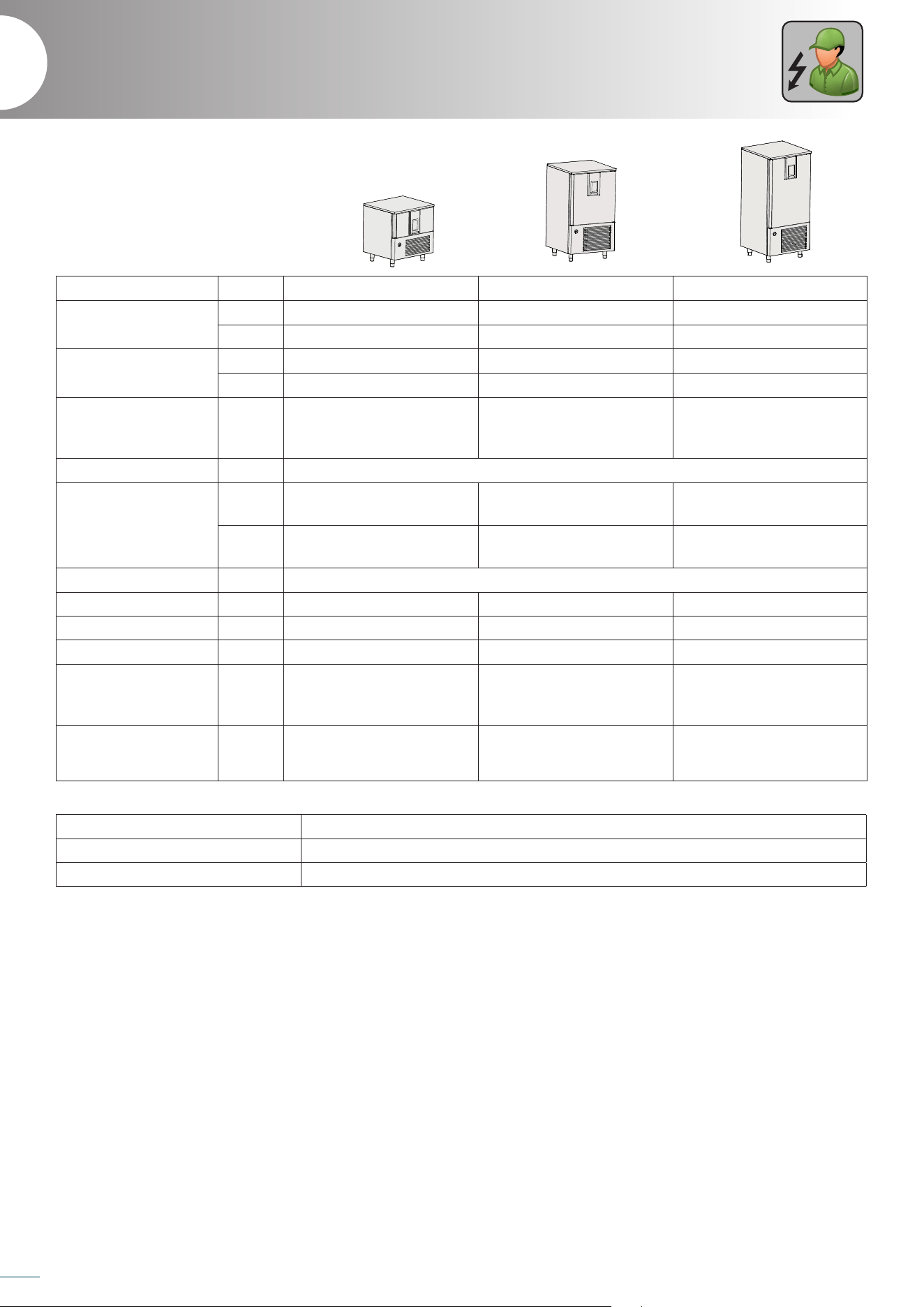
Model BCT/05 US BCT/10 US BCT/15 US
External dimensions
cm 860x960x823 86x88x153 86x89x190
inch 33.9x37.8x32.4” 33.8x34.7x61.4” 33.9x34.6x74.8”
Weight
kg 138 180 240
lbs 304 397 530
Tray capacity No.
5
18”×26” (сm 66x46) or
GN 1/1
10
18”x26” (cm 66x46) or
GN 1/1
15
18”x26” (cm 66x46) or
GN 1/1
Internal cell temperature
°C / °F +95/-40 °C / +203/-40 °F
Load capacity
kg
+3°C ÷ +65 = 20 Kg
+65°C ÷ -18°C = 12 Kg
+3°C ÷ +65 = 37 Kg
+65°C ÷ -18°C = 24 Kg
+3°C ÷ +65 = 68 Kg
+65°C ÷ -18°C = 49 Kg
lbs
+37°F ÷ +149°F = 44 lb
+149°F ÷ +0°C°F = 26 lb
+37°F ÷ +149°F = 81.5 lb
+149°F ÷ +0°C°F = 53 lb
+37°F ÷ +149°F = 150 lb
+149°F ÷ +0°C°F = 108 lb
Gas R290
Compressor power Hp 1 1.25 2x 1.25
Max absorbed power W 1045 1871 3050
Max absorbed current A 11.4 14 9.6
Supply voltage Volt
1x115V ~ 60 Hz
plug NEMA 5-20P / 5-15P
cable length 2.5 m [98.4” ]
1x230 ~ 60 Hz
plug NEMA 6-20P / 6-15P
cable length 2.5 m [98.4” ]
3x230 ~ 60 Hz
Refrigerated power
(-10°F/+130°F)
Btu/h 3445 6412 10538
Installation location Bakeries, pastry shops, ice cream parlours and kitchens in general
Air relative humidity < 80% without condensation
Climate class 5 (+40°C / +104°F 40% HR)
2
Technical data
[11.8]
700 [27.6]
780 [30.7]
30 [1.2]
780 [30.7]
[5.9]
418 [16.4]
[1.2]
860 [33.9]
362 [14.2]
[3.9]
660 [26]
[4.3]
[19.9]
[3.4]
50 [2]
700 [27.6]
870 [34.3]
960 [37.8]780 [30.7]
[11.8] [15.7]
66 [2.6] 66 [2.6]
[1.3]
33
[1.3]
33
665 [26.2]
44 [1.7] 44 [1.7]
577 [22.7]
[0.8]
310 [12.2]
[0.6]
381 [15]
30 [1.2]
810 [31.9]
33.9
28.3 2.82.8
2
31.1
63.5
32.4
21.4 11
14.9 16.9
31.9
1.615.9
37.8
14.35.9
*280 [* 11]
300
150
32
100
[3.9]
100
110
500
85
300 400
20
[0.8]
20
[0.8]
20
15
C
32.4
18.9
4.8 21.1
32.4
6.5
12.2
11.8
13.8
S
S
450 [17.7]
780 [30.7]
860 [33.9]
30 [1.2]1379 [54.3]
150
[5.9]
889 [35]
130
[5.1]
570 [22.4]
80 [3.1]
780 [30.7]
870 [34.3]
860 [33.9]
300 [11.8]
480 [18.9]
1560 [61.4]
490 [19.3]
44 [1.7]
577 [22.7]
44 [1.7]
71
[2.8]
700 [27.6]49 [1.9]
18
[0.7]
*665 [*26.2]18 [0.7]
30 [1.2]
[3.9]
660 [26]
100
[3.9]
100
50 [2]
[0.8]
20
860 [33.9]
66 [2.6] 66 [2.6]
[1.3]
33
[1.3]
33
665 [26.2]
[1.2]
32
450 [17.7]
780 [30.7]
860 [33.9]
30 [1.2]1720 [67.7]
150,3
[5.9]
1230 [48.4]
130
[5.1]
570 [22.4]
80
[3.1]
50 [2.0]
780 [30.7]
870 [34.3]
860 [33.9] 20 [0.8]
300 [11.8]
480 [18.9]
C
1900 [74.8]
490 [19.1]
66 [2.6] 66 [2.6]
665 [26,2]
1055 [41.5]
49 [1.9]
[0.8]
*1015 [*40]
30,2 [1.2]
[1.3]
33
[1.3]
33
577 [22.7]
860 [33.9]
44 [1.7] 44 [1.7]
[1.2]
32
20
[2.2]
56
[0.8]
20
[3.9]
660 [26]
100
[3.9]
100
11
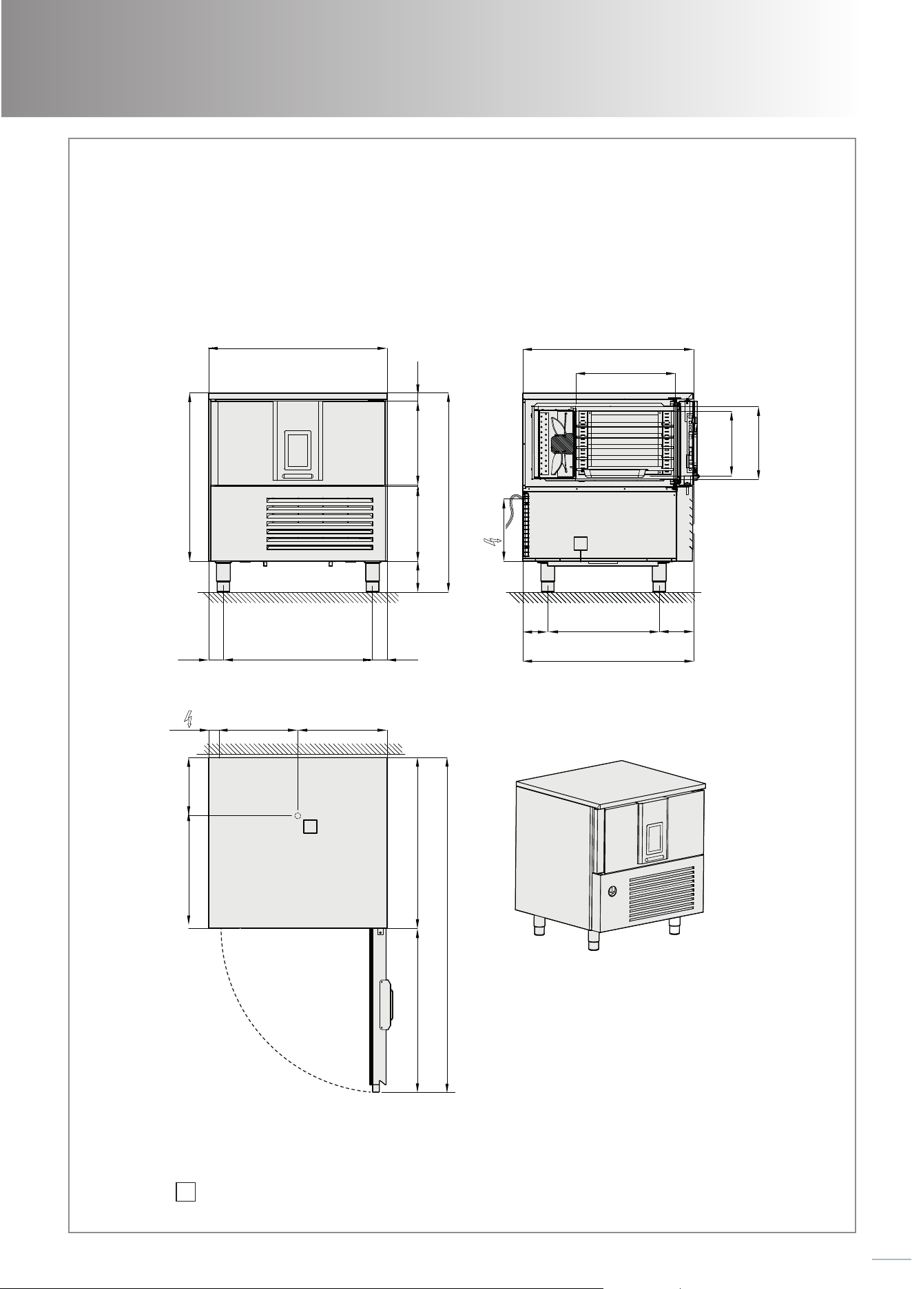
Installation diagram
33.9
28.3 2.82.8
2
31.1
63.5
32.4
21.4 11
14.9 16.9
31.9
1.615.9
37.8
14.35.9
32.4
18.9
4.8 21.1
32.4
6.5
12.2
11.8
13.8
S
S
BCT/05 US
S
DRAINING WATER = 17 HOLES, INT. 0.69”, L=11”
inch
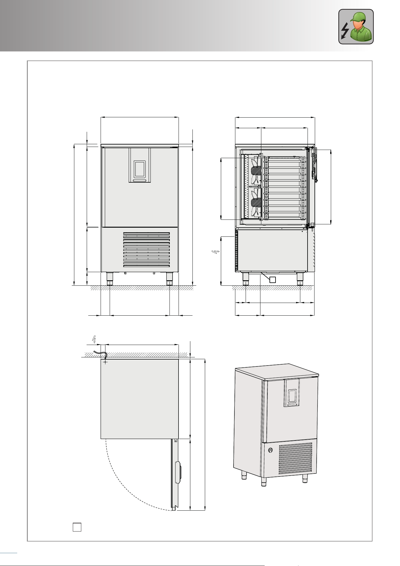
12
Service
1.2
60.2
19.3
61.4
5.9
2
34.831.1 0.8
31.9
65.9
21.3
34.7
5.8 22.4 6.2
11 23.4
32.3
26.8
11.3
20.2
33.8
1.234.80.2
25.94
4
S
BCT/10 US
S
DRAINING WATER = 17 HOLES, INT. 0.69”, L=11”
inch
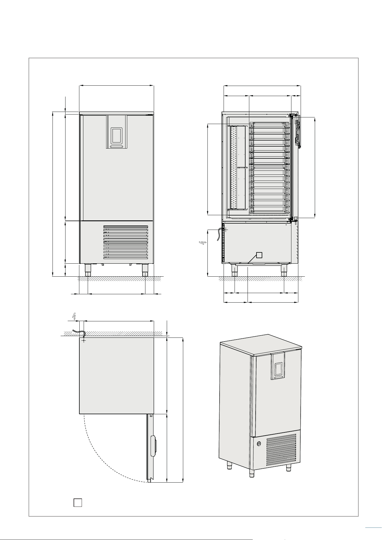
13
45.6
48.2 1.20.2
33.8
19.3
74.8
5.9
4 25.9 4
41.3
34.7
11.3 20.2 110
540
5.8 22.4 6.2
11
23.4
2
0.8
31.9
65.9
34.831.1
S
BCT/15 US
S
DRAINING WATER = 59 HOLES, INT. 17.5, L=1015mm
inch
14
Service
3
Transport, unpacking and checking
Before handling the equipment, it is mandatory to read the safety warnings on the rst pages
of this booklet.
Transport
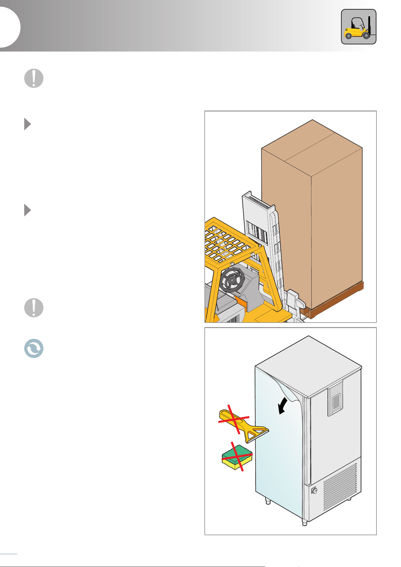
Fig. 1
Transport the still packed equipment to the place chosen for
installation using a forklift truck with a capacity greater than the
weight of the equipment to be lifted: the operator of the forklift
will be responsible for lifting the load. The use of unsuitable
equipment can lead to accidents to personnel carrying out
the operation and/or damage to the equipment.
Unpacking
Fig. 2
Before unpacking, check that there are no visible damages.
In the event of damage:
- prepare a photographic documentation of the damage;
- promptly notify the carrier/manufacturer.
If not, proceed to unpacking by removing the cardboard
surrounding the equipment.
Also remove the protective film from the ovens avoiding the use
of abrasive/aggressive substances or metal objects (e.g. scrapers).
If any residue of adhesive remains, wipe with a soft cloth
soaked in an oil-based, non-aggressive or abrasive
detergent, suitable for stainless steel surfaces. Avoid
using scrapers, abrasive or cutting tools.
As potentially dangerous, packaging material must be
kept out of the reach of children or animals and properly
disposed of according to local regulations.
Fig. 1
Fig. 2
15
Checking the appliance
Fig. 3
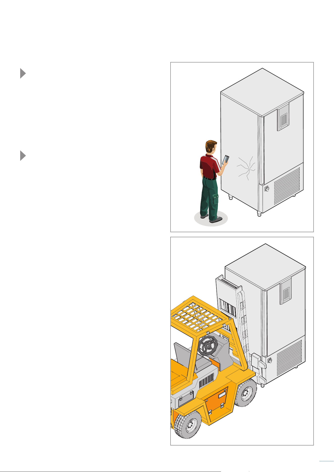
Check the integrity of the equipment, checking that it has not
been damaged during transport and that all the components
necessary for installation and use are present.
In the event of damage or missing parts:
- get the equipment data, present on the technical data plate;
- prepare a photographic documentation of the damage;
- promptly notify the carrier/manufacturer.
Handling after unpacking
Fig. 4
To move the equipment fitted with wheels, simply push
them, taking care to release the special brakes on the wheels
themselves and to re-lock them when the appliance is placed in
its final position.
To move equipment with feet, proceed with lifting it using
an appropriate forklift; the forks must be placed under the
equipment, taking care not to damage any part of it.
Fig. 3
Fig. 4
16
Service
4
Installation
Before installing and connecting the equipment, it is mandatory to read the safety warnings
on the rst pages of this booklet.
Choosing the position
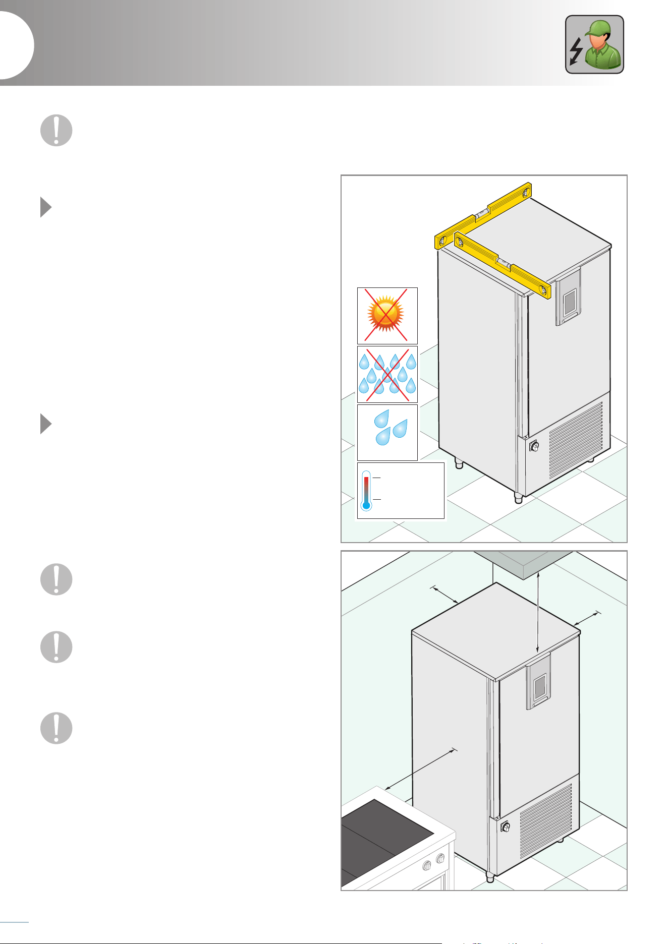
Fig. 5
The positioning room must:
- be large enough to allow handling the equipment;
- be well ventilated and not exposed to the weather;
- have a temperature between 15°C
/95°F
and 40°C/
104°F
and
humidity lower than 70%;
- have a floor without any roughness, perfectly levelled and
capable of
supporting
the equipment at full load;
- have the electrical, water and refrigeration systems necessary
for the connection that comply with current regulations in
terms of safety at work and the systems themselves;
- have good natural or artificial lighting, suitable for the operations
to be carried out (based on specific standards);
- be dedicated to preparing food.
Fig. 6
Install the equipment:
- so as to have access to water and electricity connections;
- away from flammable and/or potentially explosive materials
(e.g. gas cylinders);
- taking into account that the appliance door must be fully
opened;
- so that it is perfectly level, if necessary act on the feet;
- keeping the safety distances shown in the figure.
P
ositi
oning near other equipment that reaches high
temperatures is not recommended. If it is necessary,
provide a space of at least 50 cm/ 19.6 inch on the side
and 70 cm/ 27.6 inch in the back or erect an insulating wall.
Do not place the equipment near materials or contain-
ers of flammable material (e.g. partition walls, gas cylin-
ders, etc.) due to the fire risk. Coat any walls with
non-flammable thermal material. The equipment is not suitable
to be built-in.
When choosing the location room, take into account
that the equipment must be easily moved for any
extraordinary maintenance: take care that any masonry
works subsequent to installation (e.g. construction of walls,
replacement of doors with narrower ones, renovations, etc. ...) do
not hinder movement.
Min 15°C
Min 59°F
Max 70%
Max 40°C
Max 104°C
min.
15 cm
5.91”
min.
70 cm
27.6”
min.
20 cm
7.1”
min.
50 cm
19.69”
Fig. 5
Fig. 6
17
Electrical connection
The connection to the power supply network must comply with the regulations in force in the country of the equipment
installation and must be carried out by a specialized electrician authorized by the Manufacturer. Failure to comply with
these rules may cause damage and injury, void the warranty and release the Manufacturer from all liability.
Before proceeding with the electrical connection, always compare the system data with those shown on the
technical data plate.
When the appliance is in operation, the value of the supply voltage must not dier by +/-10% of the value shown
on the technical data plate.
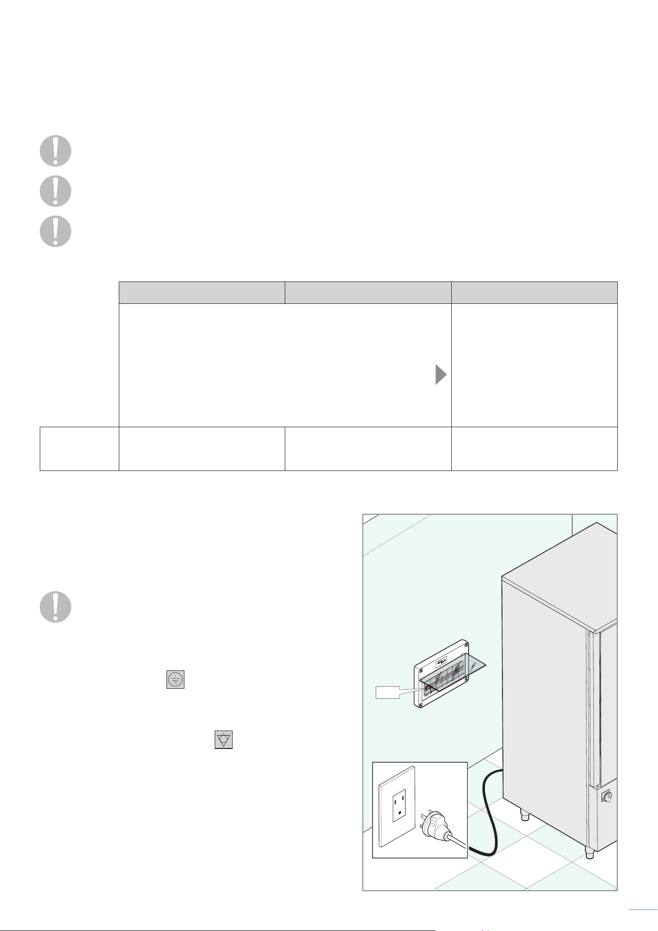
Depending on the model, different electrical connections are required:
BCT/05 BCT/10 BCT/15
The equipment is supplied by the manufacturer complete with a power
cord and plug.
Connected the equipment to a power outlet in the installation’s site
Fig. 7
The equipment is supplied with
a power cord and is NOT supplied
with a plug.
A specialized electrician
authorized by the Manufacturer must:
A) fit a
plug
on the power cord
or, a
lternatively
B) remove the supplied electrical
cable and connect a new electrical
cable to own electrical panel
Supply voltage
1x115 Volt 60Hz
plug NEMA 5-20P / 5-15P
cable length 2.5 m [98.4” ]
1x230 Volt ~ 60 Hz
plug NEMA 6-20P / 6-15P
cable length 2.5 m [98.4” ]
3x230 Volt ~ 60 Hz
OFF
Fig. 7
Make sure that the cable:
- has no tight kinks;
- is not crushed by objects or other equipment;
- is not in contact with sharp or hot objects;
- does not hinder the passage of people.
Upstream, the equipment must be provided with an
easily accessible switch installed in the system accord-
ing to the regulations in force in the country of installa-
tion of the equipment. This switch must have an omnipolar con-
tact separation so as to guarantee complete disconnection
under overvoltage category III.
A correct earth connection
is mandatory and the earth ca-
ble must not be interrupted in any case by the protection switch.
When there are several appliances in the same room, it is manda-
tory to provide an equipotential connection using the appro-
priate terminal marked with the symbol
. This terminal allows
you to connect an earth cable according to the current legal re-
quirements. The effectiveness of the equipotential system must
be properly checked according to what is stated in the current
legislation.
If it is necessary to disconnect the power plug, first make sure
that the card is positioned to OFF on the display.
The manufacturer declines all responsibility for damage or acci-
dents caused by failure to comply with these standards.
18
Service
Connection to the waste water network
Fig. 8
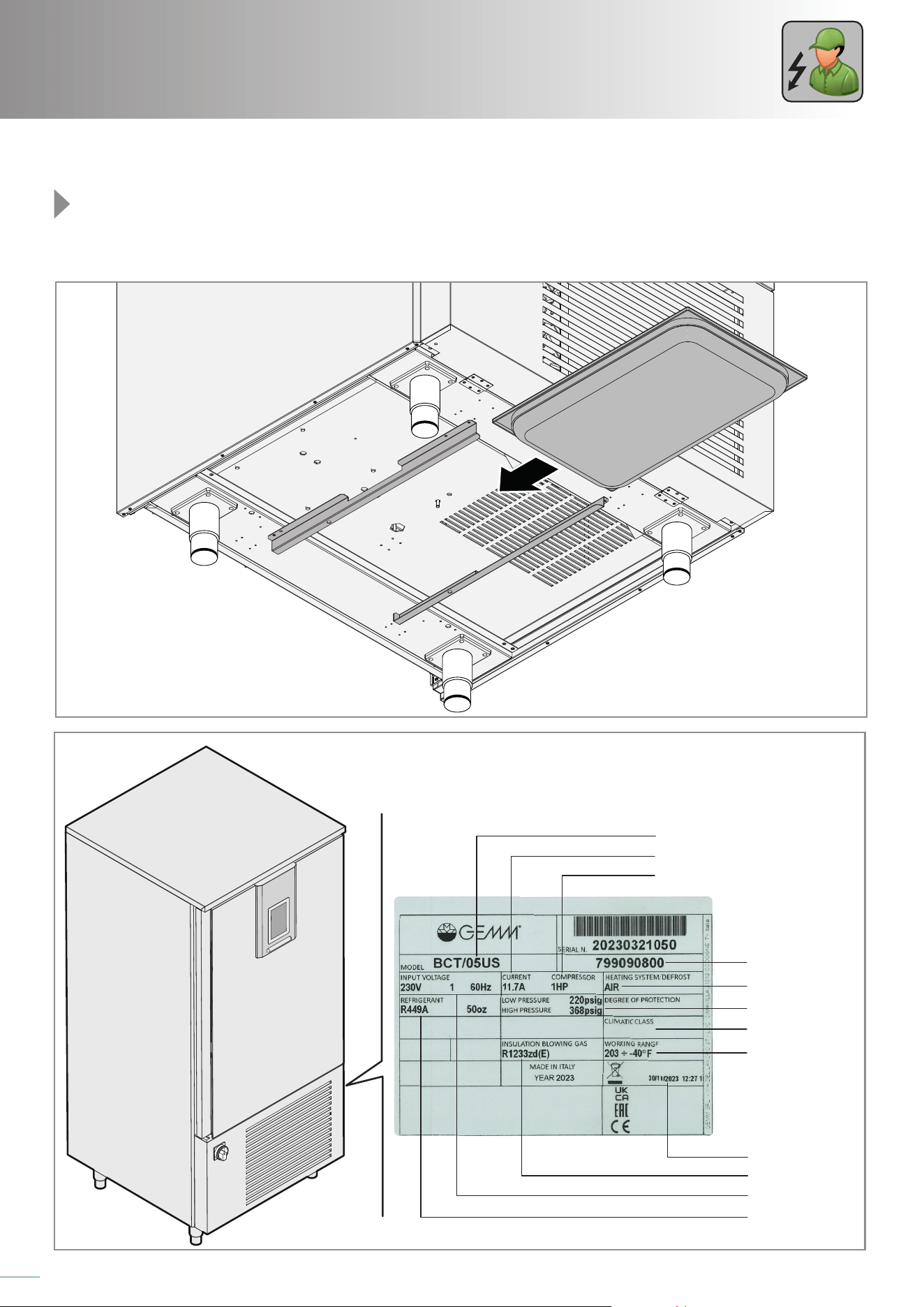
The equipment leaves the factory equipped with a GN 1/1 tray placed under it which must be periodically checked, emptied and
cleaned.
Fig. 8
Fig. 9
Model
Working pressure
Climatic class
Absorbed current
Compressor Power
Type of defrost
Serial number
Working range
Blowing agent
Voltage
Refrigerant type
and quantity
Date of production
dd/mm/yyyy
Production time
hh/mm/ss

19
Personal notes
20
Service
5
Final checks
In R449A appliances there is a compressor oil heater, once the machine rst starts the standby
mode (main switch on and LED board o), it is necessary to wait at least 2 hours before start-
ing a blast chilling cycle.
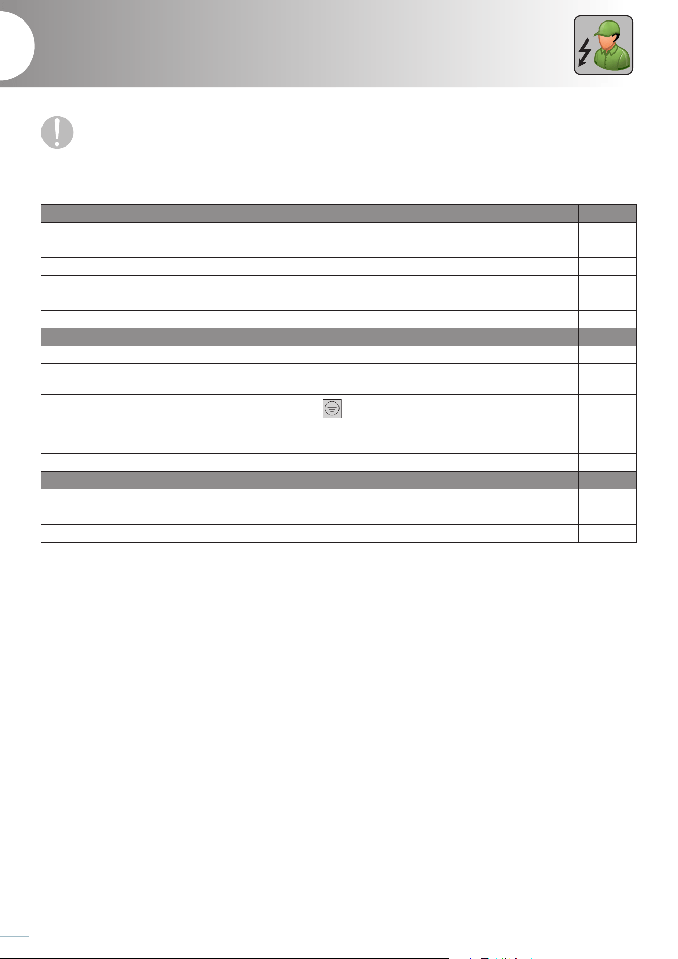
Final checks
Positioning checks YES NO
Was the adequacy of the installation rooms checked (minimum/maximum temperature, etc ...)?
Is the appliance perfectly level?
Have the minimum distances from walls (15 cm/5,9 inch) and from other equipment (50 lateral) been complied with?
Has the protective film been removed from all surfaces?
Is the equipment perfectly intact, with no visible damage?
Is the inside of the equipment free of non-compliant objects (booklets, plastic bags, etc ...)?
Electrical checks YES NO
Do the characteristics of the network comply with the data found on the technical data plate?
Was the electrical connection made according to the regulations in force in the country of installation of the equip-
ment by a skilled electrician authorized by the Manufacturer?
Is the equipment provided with a correct earth connection
(the earth cable must in no case be interrupted by
the protection switch)?
Is the equipment connected to an equipotential system?
Is there an easily accessible switch upstream of the equipment?
General checks YES NO
Does the door close correctly?
Does the compressor turn off when the appliance reaches the set temperature?
Does the user have all the necessary documentation? Has he been correctly trained on the use of the machine?
PURCHASE INVOICE
Date ....................................Number .............................................................................
APPLIANCE DATA (FROM DATA PLATE)
Model: ...............................................................................................................................
Serial number (Ser. No.): ........................................................................................
CUSTOMER DETAILS
Name and Surname: ................................................................................................
Company name: .........................................................................................................
Address 1: ............................................................................Address 2: ...................
Town: ......................................................................................... Province: ...................
INSTALLER’S STAMP AND SIGNATURE
INSTALLER DETAILS
Name and Surname: ................................................................................................
Company name: .........................................................................................................
Address 1: ............................................................................Address 2: ...................
Town: ......................................................................................... Province: ...................
Tel/Email: .........................................................................................................................

21
USE
Service
Preliminary knowledge ........................................................................................................ 22
Knowing the appliance .......................................................................................................................................................................22
Protection devices ..................................................................................................................................................................................24
How to get the best from the appliance ..................................................................................................................................25
Arranging the food inside the cell ...........................................................................................................................................................25
Maximum load tableCarrying out scheduled maintenance ...................................................................................................25
Using the needle probe correctly .............................................................................................................................................................25
Use ............................................................................................................................................ 26
Switching on .............................................................................................................................................................................................. 26
Keypad lock/unlock ............................................................................................................................................................................... 27
Silencing the acoustic signal............................................................................................................................................................27
Door open warning ...............................................................................................................................................................................27
Setting the language, date and time ..........................................................................................................................................27
Blast chilling/freezing ........................................................................................................................................................................... 28
Setting and starting a blast chilling/freezing cycle .......................................................................................................................28
Blast chiller ............................................................................................................................. 28
Saving a cycle with the desired parameters ......................................................................................................................................30
Modifying a cycle parameters .....................................................................................................................................................................31
Continuous cycle ....................................................................................................................................................................................32
Customized cycle ....................................................................................................................................................................................33
Pre-cooling ............................................................................................................................. 34
Recipe book ............................................................................................................................ 36
Modifying a recipe and saving it with another name ...................................................................................................... 37
Fish sanitization ........................................................................................................................................................................................38
Special cycles .......................................................................................................................... 38
Thawing ........................................................................................................................................................................................................39
Defrosting .................................................................................................................................................................................................... 39
Sterilization ..................................................................................................................................................................................................39
Ice cream hardening ............................................................................................................................................................................. 39
Drying .............................................................................................................................................................................................................39
Recipe download/upload ..................................................................................................................................................................40
Parameter download/upload .......................................................................................................................................................... 40
Parameter download/upload .......................................................................................................................................................... 40
USB ........................................................................................................................................... 40
Ordinary maintenance ......................................................................................................... 42
Scheduling the cleaning ....................................................................................................................................................................42
Cleaning the internal cell and external parts.........................................................................................................................43
Cleaning the condenser .................................................................................................................................................................... 43
Cleaning the needle probe ...............................................................................................................................................................44
Downtime ....................................................................................................................................................................................................44
Disposal .........................................................................................................................................................................................................45
After-sales service ................................................................................................................. 46
Warranty........................................................................................................................................................................................................46
22
Service
Knowing the appliance
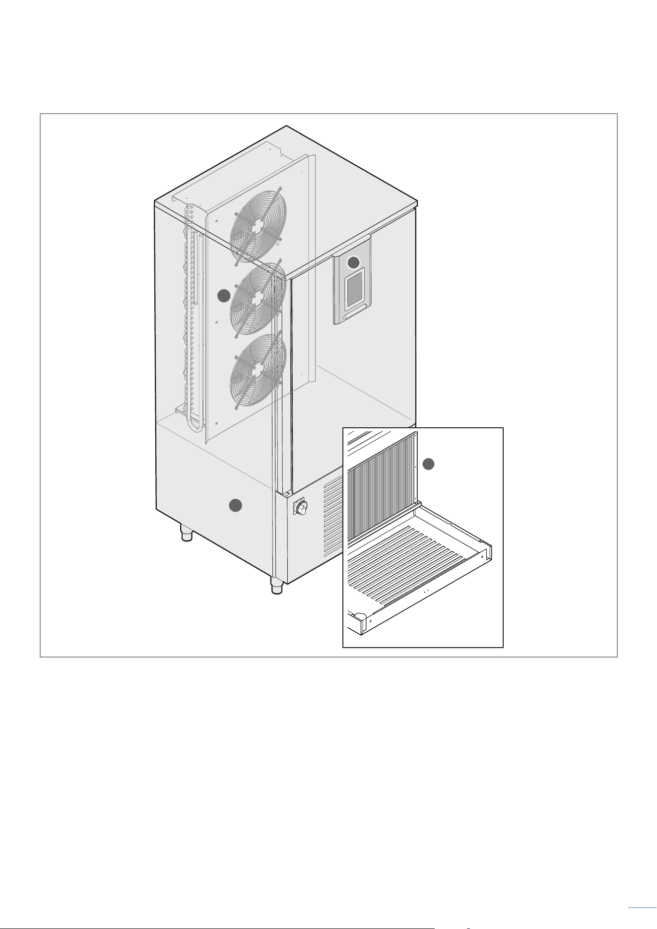
Fig. 10
The blast chiller is an appliance with a powerful refrigeration system capable of rapidly lowering the core temperature of food Its
use is ideal in any kitchen, bakery and ice cream parlour.
The appliance consists of the following components:
1
appliance body;
2
condensing unit (only for equipment with integrated unit);
3
evaporating unit (only for equipment with integrated unit);
4
control panel;
5
stop function.
The work cycles that the machine can carry out are:
- BLAST CHILLING Positive blast chilling (3°C/37°F). The freshly baked product is brought to a temperature of 3°C/37°F in a short
time, thus inhibiting bacterial proliferation and avoiding dehydration by evaporation of the cooked product.
The product thus treated can be perfectly stored for 5-7 days without altering its organoleptic qualities. The
HARD function is used when the product to be cooled is large in size (thickness greater than 2-3 cm / 0,7-1,1
inch) or is particularly fatty. The equipment develops variable air temperatures to accelerate the penetration of
the cold into the product.
- FREEZING Negative blast chilling (deep freezing) (-18°C/0°F). This work cycle allows to quickly bring the core of the
product to a temperature of -18°C/0°F. The speed of the process avoids the formation of macro crystals ensuring
that, at the time of final use, the thawed food has the original consistency, colour and quality. The SOFT function
is used when the product to be cooled is particularly delicate.
- STORAGE At the end of each cycle, both positive and negative blast chilling, the appliance will automatically adopt the
expected storage temperature.
Each blast chilling (both negative and positive) provides two dierent end cycle modes after which storage begins:
temperature execution end: the cycle ends when the needle probe inserted in the core of the product reaches the set
temperature;
timed execution end: the cycle ends when the set time is reached.
This blast chiller is not an equipment suitable for the indefinite storage of food.
DANGER OF FROSTBITE: during its work phases, the appliance can manage very low temperatures, avoid direct contact with
the internal parts of the machine immediately after opening the door.
Preliminary knowledge
6
Before using the appliance, it is mandatory to read the safety warnings listed in the rst pages
of this booklet.
23
3
4
1
2
Fig. 10
24
Service
Protection devices
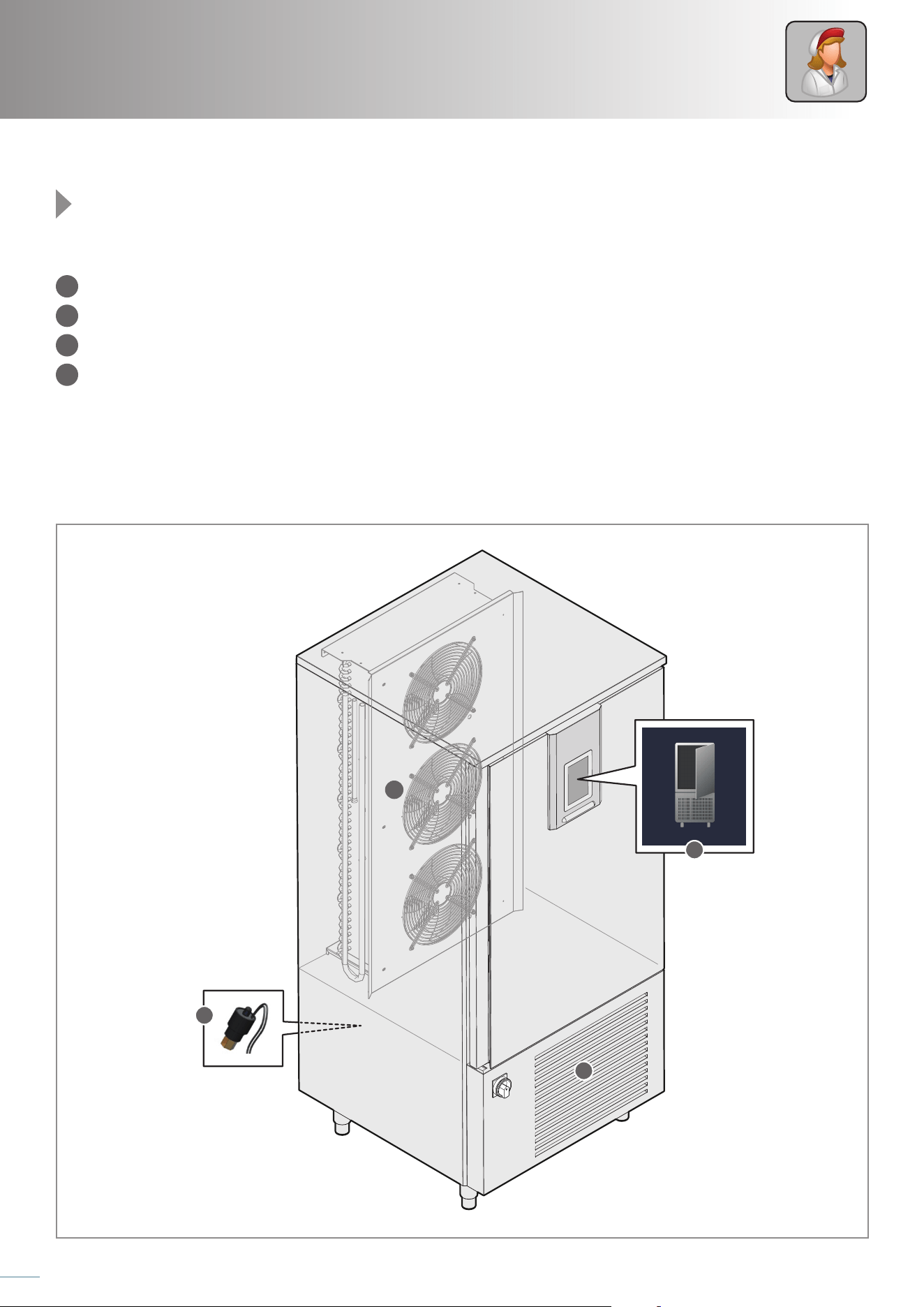
Fig. 11
The protection of the personnel exposed to the risks due to dangerous mobile elements is guaranteed by the presence of suitable
devices on the appliance:
1
grilles covering the cooling fans;
2
grille covering the condensing unit;
3
sensor located on the cooling circuit: signals any system overheating and pressure by putting the machine on standby;
4
sensor that detects and signals the opening of the door. If the door remains open for a time longer than a pre-set parameter, the
icon will appear on the display, an acoustic signal will sound and then the compressor will shut down.
3
1
2
4
Fig. 11
25
How to get the best from the appliance
Arranging the food inside the cell
The foods to be chill blasted must be placed, in a single layer, in containers with low edges and suitable for food use.
Arrange them homogeneously and evenly inside the cell.
Correct positioning of the containers will allow the free circulation of air inside the latter: avoid obstructing the ventilation fans and
overloading the equipment beyond the permitted limits.
Maximum load table
Model BCT/05 US BCT/10 US BCT/15 US
Tray capacity No.
5
18”×26” (сm 66x46) or
GN 1/1
10
18”x26” (cm 66x46) or
GN 1/1
15
18”x26” (cm 66x46) or
GN 1/1
Internal cell temperature
°C / °F +95/-40 °C / +203/-40 °F
Load capacity
kg
+3°C ÷ +65 = 20 Kg
+65°C ÷ -18°C = 12 Kg
+3°C ÷ +65 = 37 Kg
+65°C ÷ -18°C = 24 Kg
+3°C ÷ +65 = 68 Kg
+65°C ÷ -18°C = 49 Kg
lbs
+37°F ÷ +149°F = 44 lb
+149°F ÷ +0°C°F = 26 lb
+37°F ÷ +149°F = 81.5 lb
+149°F ÷ +0°C°F = 53 lb
+37°F ÷ +149°F = 150 lb
+149°F ÷ +0°C°F = 108 lb
[11.8]
700 [27.6]
780 [30.7]
30 [1.2]
780 [30.7]
[5.9]
418 [16.4]
[1.2]
860 [33.9]
362 [14.2]
[3.9]
660 [26]
[4.3]
[19.9]
[3.4]
50 [2]
700 [27.6]
870 [34.3]
960 [37.8]780 [30.7]
[11.8] [15.7]
66 [2.6] 66 [2.6]
[1.3]
33
[1.3]
33
665 [26.2]
44 [1.7] 44 [1.7]
577 [22.7]
[0.8]
310 [12.2]
[0.6]
381 [15]
30 [1.2]
810 [31.9]
33.9
28.3 2.82.8
2
31.1
63.5
32.4
21.4 11
14.9 16.9
31.9
1.615.9
37.8
14.35.9
*280 [* 11]
300
150
32
100
[3.9]
100
110
500
85
300 400
20
[0.8]
20
[0.8]
20
15
C
32.4
18.9
4.8 21.1
32.4
6.5
12.2
11.8
13.8
S
S
450 [17.7]
780 [30.7]
860 [33.9]
30 [1.2]1379 [54.3]
150
[5.9]
889 [35]
130
[5.1]
570 [22.4]
80 [3.1]
780 [30.7]
870 [34.3]
860 [33.9]
300 [11.8]
480 [18.9]
1560 [61.4]
490 [19.3]
44 [1.7]
577 [22.7]
44 [1.7]
71
[2.8]
700 [27.6]49 [1.9]
18
[0.7]
*665 [*26.2]18 [0.7]
30 [1.2]
[3.9]
660 [26]
100
[3.9]
100
50 [2]
[0.8]
20
860 [33.9]
66 [2.6] 66 [2.6]
[1.3]
33
[1.3]
33
665 [26.2]
[1.2]
32
450 [17.7]
780 [30.7]
860 [33.9]
30 [1.2]1720 [67.7]
150,3
[5.9]
1230 [48.4]
130
[5.1]
570 [22.4]
80
[3.1]
50 [2.0]
780 [30.7]
870 [34.3]
860 [33.9] 20 [0.8]
300 [11.8]
480 [18.9]
C
1900 [74.8]
490 [19.1]
66 [2.6] 66 [2.6]
665 [26,2]
1055 [41.5]
49 [1.9]
[0.8]
*1015 [*40]
30,2 [1.2]
[1.3]
33
[1.3]
33
577 [22.7]
860 [33.9]
44 [1.7] 44 [1.7]
[1.2]
32
20
[2.2]
56
[0.8]
20
[3.9]
660 [26]
100
[3.9]
100
Carrying out scheduled maintenance
Regular and correct maintenance ensures optimal performance and a longer life of the equipment.
see chapt. “Ordinary maintenance” on page 42.
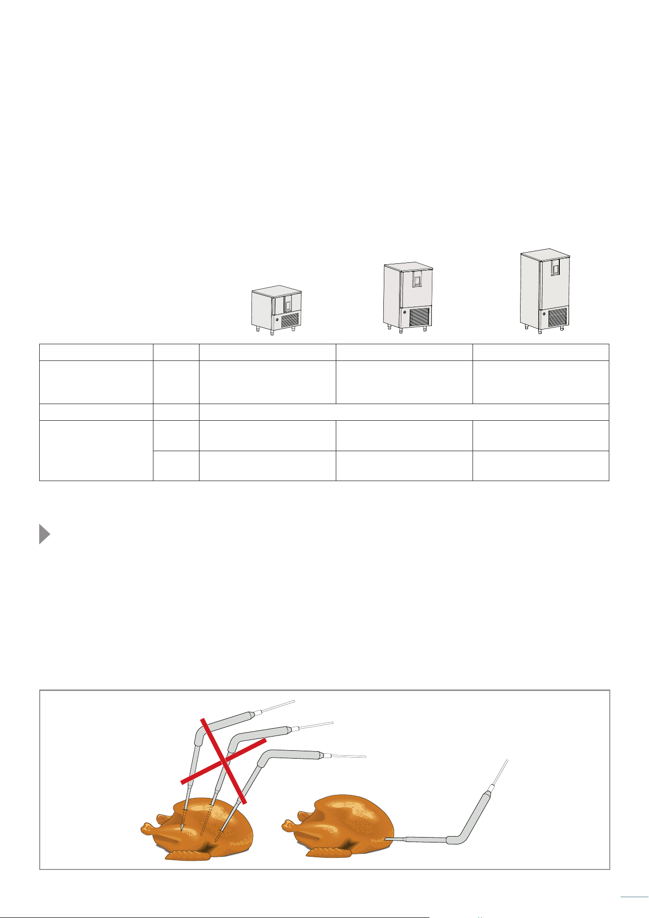
Using the needle probe correctly
The needle probe, during blast chilling, detects the temperature at the "heart" of the food: when it reaches 3°C/ 37°F or -18°C/ 0°F, the
cycle ends (if selected with a needle probe and not timed).
The needle probe must be inserted deeply into the food to be blast chilled: make sure that its tip reaches the "core" of the food, that
is, its innermost point, without coming out. Be careful not to stick it in very fat spots or close to the bones.
If the food is not very thick, insert the probe parallel to the support surface.
We recommend you always keep the probe clean and sanitized.
Fig. 12
OK
> LOADING...
11:3817/02/15
premere per accendere
21
4
3
Fig. 13
26
Service
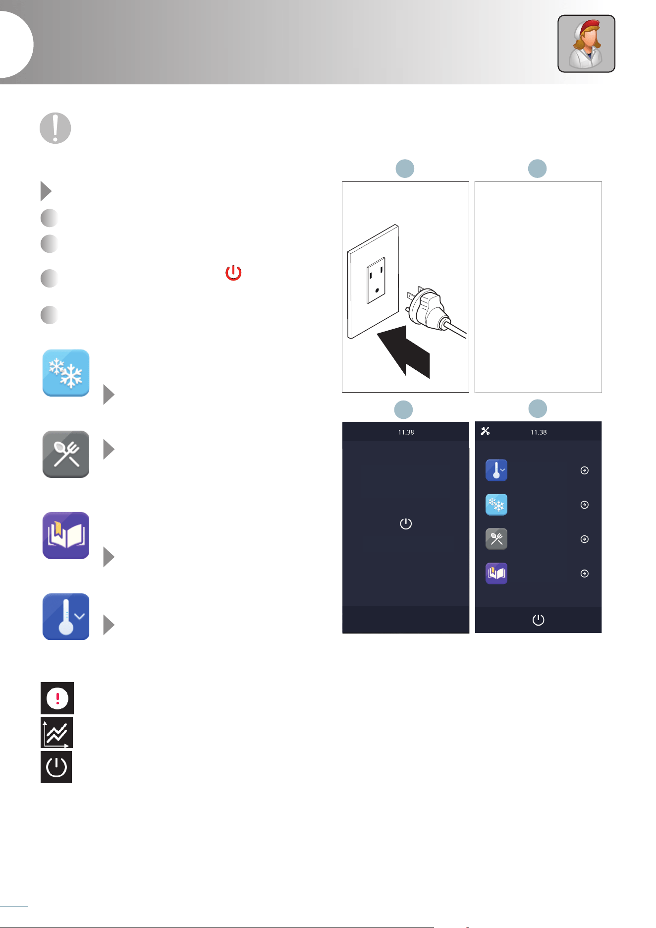
Switching on
Fig. 13
1
Connect the power supply of the appliance.
2
The device will display a loading screen (LOADING...) for a
few seconds.
3
A stand-by screen opens; press the button to access
the HOME PAGE screen.
4
From the HOME PAGE screen you can select the desired
function:
Allows you to select the blast chiller mode,
where you can select or set a blast chilling or
deep freezing cycle.
see page 28
Allows you to select the special cycles mode
see chapt. 38
Allows you to select the recipe book mode,
where factory-set and personal recipes are avail-
able.
see page 36
Allows you to activate a cell pre-cooling cycle.
see page 34
The symbols on the screen also provide useful information:
alarm in progress
pressing the symbol allows you to view the
historical data recorded during operation
returns to the stand-by function
Use
7
Before using the appliance, it is mandatory to read the safety warnings listed in the rst pages
of this booklet.
Blast chiller
press to switch on
Pre-Cooling
Special Cycles
Recipe book
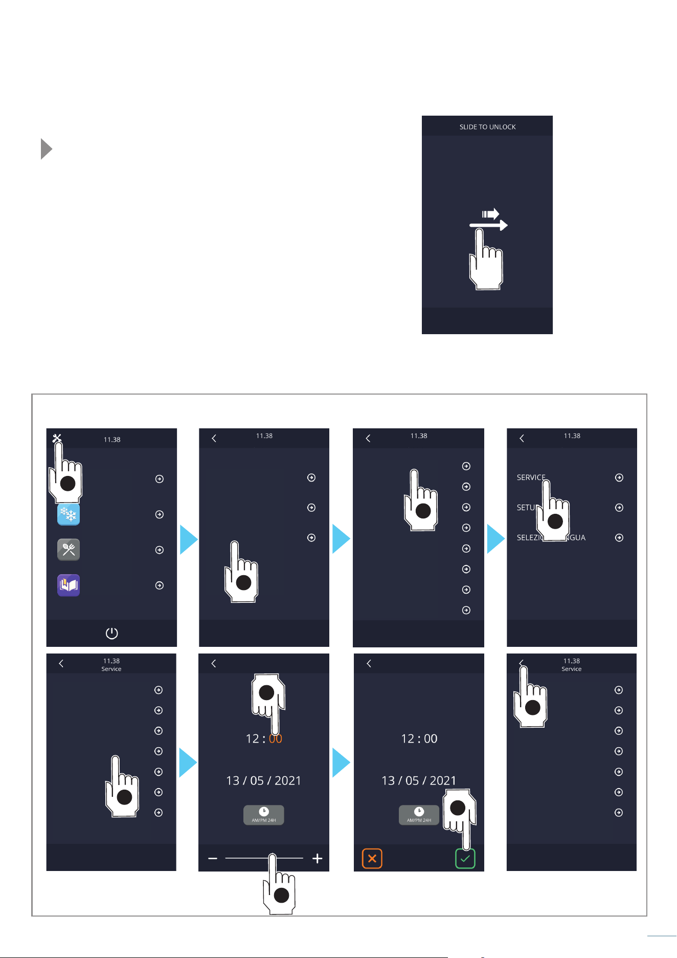
Fig. 14
Fig. 15
27
Keypad lock/unlock
Fig. 14
The keyboard is locked after a certain factory-set inactivity time: a
message appears on the screen and any operation is prevented.
To unlock it, drag the slider sliding your finger to the right.
Silencing the acoustic signal
To silence the acoustic signal, touch any area of the display while
the sound is in progress.
Door open warning
When the door is opened, the alarm message appears on the
display. Touch any area of the display to get rid of the message.
Setting the language, date and time
Abbattitore
Pre-Cooling
Cicli Speciali
Blast chiller
Pre-Cooling
Settings
Settings Settings
Date / time
Date / time
SERVICE
SERVICE
ITALIANO
ENGLISH
FRANCAIS
DEUTSCH
ESPANOL
PORTOGUES
CINESE
GIAPPONESE
SETUP
SETUP
LANGUAGE SELECTION
LANGUAGE SELECTION
INPUT AND OUTPUT STATUS
INPUT AND OUTPUT STATUS
OPER. HOURS COMPRESSOR
OPER. HOURS COMPRESSOR
DATE/TIME SETTING
DATE/TIME SETTING
HACCP DATA SELECTION
HACCP DATA SELECTION
RESET OPER. HOURS COMPR
RESET OPER. HOURS COMPR
HACCP ALARM RESET
HACCP ALARM RESET
ALARMS
ALLARMI
Special Cycles
Recipe book
1
2
3
4
8
4
6
7
5
28
Service
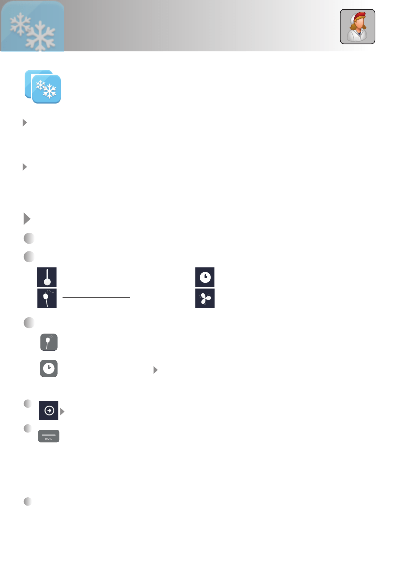
Setting and starting a blast chilling/freezing cycle
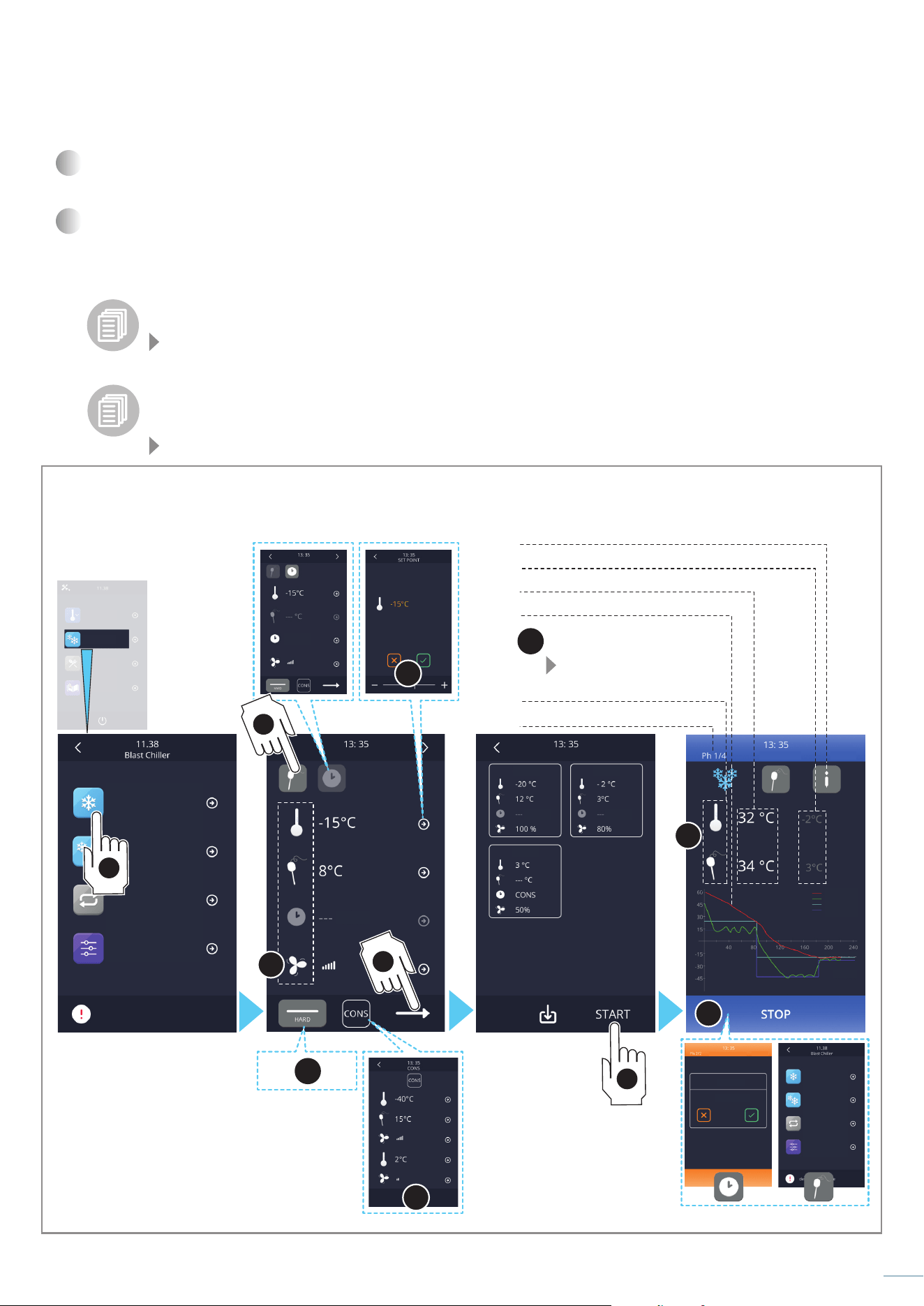
Fig. 16
1
Select the desired cycle (blast chilling +3°C/37°F or deep freezing -18°C/0°F). Both cycles consist of a blast chilling/deep freezing
phase, followed by a storage phase which, if not interrupted, has an infinite duration.
2
The display shows the settings of the phase of the chosen cycle:
temperature to be reached in the cell timed cycles: cycle duration in minutes
cycles with needle probe: temperature that the
probe must reach to end the cycle
fan speed
3
Choose if you wish to set a cycle with needle probe (“probe” icon) or a time one (“clock” icon):
...
the cycle ends when the needle probe detects that the temperature of the core it is inserted in has reached +3°C/
37°F
(blast chilling) or -18°C
/0°F
(deep-freezing). This mode is recommended so you can be certain that the food has been
properly blast chilled.
...the cycle ends after the set time rather than when the core temperature is reached: the default duration is 90 minutes
but it can be changed as you wish See chapt. “Modifying a cycle parameters” on page 31.
The two modes (needle probe and time) are mutually exclusive).
In the same screen you can:
3a
...make changes to the pre-set parameters (e.g. change the fan speed)
See chapt. “Modifying a cycle parameters” on page 31.
3b
...select the HARD (it is used when the product to be blast chilled is large or particularly fat) or SOFT function (delicate
deep-freezing).
Both cycles consist of two blast chilling phases with different parameters and a subsequent storage phase.
- 1
st
phase ("hard" for blast chilling and "soft" for deep freezing) with modifiable parameters;
- 2
nd
blast chilling/deep freezing phase with modifiable parameters;
- 3
rd
storage phase with modifiable parameters.
The end of a phase is signalled by an acoustic signal, then it automatically passes to the next. Also for this cycle it is
possible to select the time mode: in this case the passage to the next phase is given by the expiry of the time.
3c
... access settings reserved for expert personnel.
Blast chilling/freezing
In blast chiller mode you can choose between two different cycles:
POSITIVE BLAST CHILLING
+3°C/+37°F
The freshly baked product is brought to a temperature of 3°C/ 37°F in a short time, thus inhibiting bacterial proliferation and avoiding
dehydration by evaporation of the cooked product. The product thus treated can be perfectly stored for 5-7 days without altering its
organoleptic qualities.
NEGATIVE BLAST CHILLING (DEEP FREEZING)
-18°C/ 0°F
This work cycle allows to quickly bring the core of the product to a temperature of -18°C/0°F. The speed of the process avoids the
formation of macro crystals ensuring that, at the time of final use, the thawed food has the original consistency, colour and quality.
Blast chiller
min
6
3b
6a
6b
3a
3c
2
Fig. 16
29
phase being executed
temperature graph
current temperature in the chamber/at the core
temperature to be reached in the chamber/at the core
allows modifying the settings of
the cycle in progress:
See chapt. “Modifying a cycle
parameters” on page 31
TIMED CYCLE
NEEDLE PROBE CYCLE
opens an information screen
- probe values
- input/output status
- any alarms in progress
4
Press the “summary” key: a summary screen of the parameters of the blast chilling and storage phases relative to the selected
cycle is displayed: moreover, if parameters have been modified, it is possible to check them.
5
Close the door and press the “start” button to start the cycle (be careful, if you use a cycle with needle probe, remember to insert
it in the food to be blast chilled). If the cycle uses a needle probe, a test is performed to verify the correct insertion of the same
into the food to be blast chilled: if the test is not passed, the cycle automatically switches to timed mode: an acoustic signal starts
and the display shows the symbol of the alarm in progress.
Before starting the cycle, if changes have been made to the parameters, it is possible to save the cycle with the new
settings.
See chapt. “Saving a cycle with the desired parameters” on page 30
During the execution of a cycle, the temperature values of the enabled probes, the activations of the outputs, the status
of the inputs, the execution of the defrost cycles and the presence of any alarms are recorded. These data are available
for subsequent download with a USB device.
See chapt. USB on page 40
Freezing -18°C
Freezing -18°C
Blast chiller
Blast chilling+3°C
Blast chilling+3°C
Pre-Cooling
Continuous
Continuous
Save?
MAINTENANCE
recipe
Special Cycles
Customized
Customized
alarm description
Recipe book
BLAST CHILLING
BLAST CHILLING
START
STOP
IN PROGRESS
Summary
1 min
223 min
T needle
Set needle
set needle
set cell
Set cell
T cell
Phase 1
Phase 3
Phase 2
min
min
90 min
5
1
4
3
4
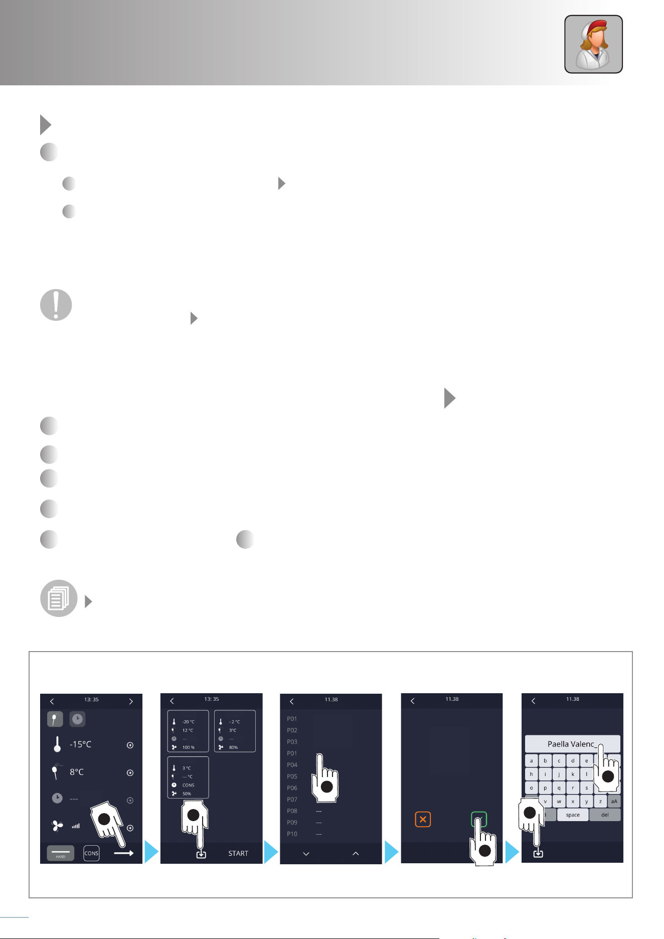
Fig. 17
30
Service
Fig. 16
6
The cycle in progress screen appears.
During the cycle in progress it is always possible to:
6a
change the settings of the phase in progress See chapt. “Modifying a cycle parameters” on page 31.
6b
block the cycle before its effective end by pressing the “stop” button: if the cycle was timed, the initial screen will be dis-
played, if the cycle was with needle probe, the possibility is given to save the recipe.
Once the blast chilling/deep freezing cycle has ended, because the temperature of the needle probe has been reached or because
the time has expired, an acoustic signal is emitted and the storage phase begins which, if not interrupted, has an infinite duration.
If the cycle with the needle probe does not end within the time set in the factory, the anomaly will be signalled by the
presence of the alarm icon, but the blast chilling cycle will continue anyway. A cause might be overloading the appliance
beyond its loading limits See chapt. “Maximum load table ” on page 25.
Saving a cycle with the desired parameters
If changes have been made to the parameters of a cycle that is then started ("start"), the changes made will have an effect only on
the cycle in progress: this means that once the cycle is finished, if you reuse it, it will not have the changes made earlier. For this reason
it may be better to save the modified cycle so that you can reuse it every time you wish to.
Fig. 17
1
Modify a cycle parameters as explained in chapt. “Modifying a cycle parameters” on page 31.
Touch the “summary” button to display the parameters of all the cycle phases.
2
Touch the “save” button.
3
Touch the position where you want to save the modified cycle. If you select a position already occupied, a screen appears asking
for confirmation before overwriting the recipe.
4
Touch “√” to confirm the insertion of a new name.
5
Enter the desired name and touch and
6
confirm the entered name.
To start a saved cycle, access the “Recipe book” - “my recipes”section, select its name and press the “start” button.
Do you want to set up a completely customized cycle, using up to 4 phases?
See chapt. “Customized cycle” on page 33
BLAST CHILLING
Summary
Save recipe
chicken
lasagne
roastbeef
Save recipe
Save recipe
Recipe name
Phase 1
Phase 3
Phase 2
min
min
min
3
4
5
1
2
6
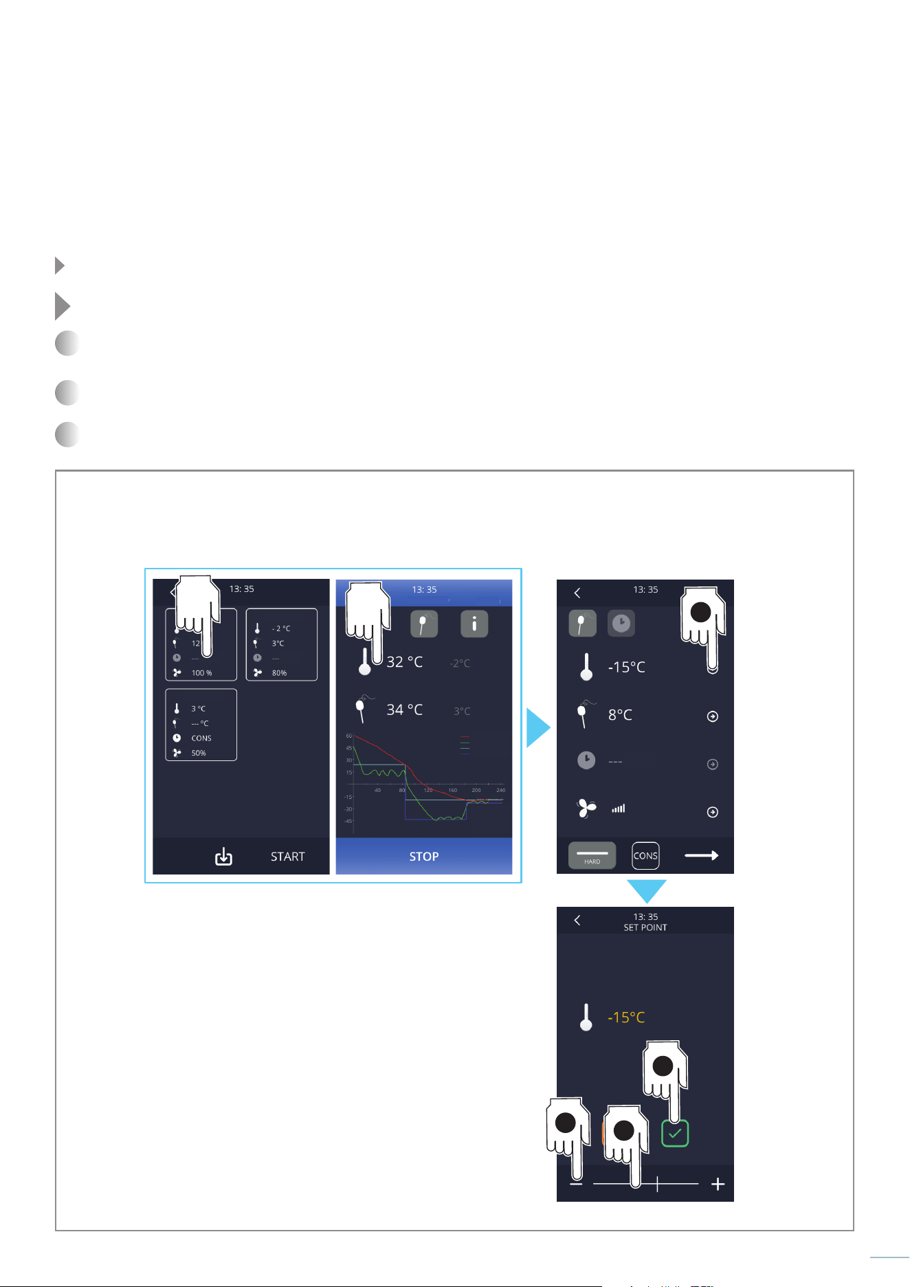
Fig. 18
31
Modifying a cycle parameters
The modification of the parameters of a cycle can be carried out before starting the cycle or during its execution.
In both cases the changes are temporary, that is, they only apply to the cycle that will be started or that is in progress.
If you want the changes made to be permanent, you must save the cycle with a name of your choice: in this way you can reuse it as
many times as you want.
See chapt. “Saving a cycle with the desired parameters” on page 30
Fig. 18
1
Touch the “pencil” symbol corresponding to the parameter you wish to modify (in the example the cell temperature is to be
modied).
2
Act on the symbols “+” or “-” or drag the cursor to enter the desired value within the expected range.
3
Touch “√” to confirm or “x” to exit the screen without saving.
Changing parameters
during a cycle in progress
Changing the parameters
from the "summary" page
BLAST CHILLING
STOP
IN PROGRESS
Summary
1 min
T needle
Set needle
set needle
set cell
Set cell
T cell
Phase 1
Phase 3
Phase 2
min
minmin
1
3
2a
2b
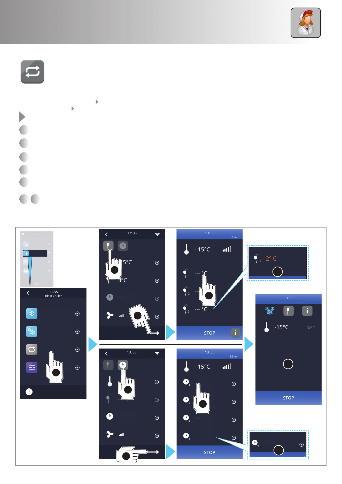
Fig. 19
7
STOP
STOP
°C
°C
°C
8
2
12
2
3
1
6
6
32
Service
Continuous cycle
The continuous cycle function is useful when you want to blast chill/freeze at the same time foods that have different
processing times. The foods must be inserted into the cell all at the same time; an acoustic signal and a message on the
display will warn when it is time to remove a food from the cell as it has been blast chilled.
The end of the cycle can be managed:
- using up to three needle probes a signal will be given when each probe detects that the set temperature has been reached;
- setting up to 4 timers a signal will be given when the time set for each timer has expired.
Fig. 19
1
Place the foods into the cell: if you decide to use the needle probes (up to three), insert them into the food: choose three different
sizes, e.g. one in a small piece, one in a medium one, one in a large one.
2
Select the "continuous cycle" function.
3
Touch the “probe” or “clock” symbol to select blast chilling with the needle probe (ends when the probe detects the set tempera-
ture) or timed (ends at the end of the set time).
4
Touch the “summary” button.
5
Set the desired probe temperatures or times (up to three probes and up to 4 timers are available): the countdown of the timers
or the probe temperature measurements start immediately, without needing to perform any other operation.
6 7
A food has reached the expected core temperature or its timer has expired; the temperature or the timer turn green, an
acoustic signal and a message warn that it can be taken from the cell while the others continue processing without the
need for any other operation. The cycle ends only when all the needles have reached the set temperature, when all the timers have
expired or if the "stop" key is pressed, afterwards it automatically passes to the storage phase.
TIMED CYCLE NEEDLE PROBE CYCLE
Freezing -18°C
Blast chiller
Blast chilling+3°C
Pre-Cooling
Continuous
Special Cycles
Customized
alarm description
Recipe book
IN PROGRESS
IN PROGRESSCONTINUOUS
CONTINUOUS
MAINTENANCE
32 min
32 min
min
min
min
min
min
0 min
68 min
2
3
5
5
3
4
4
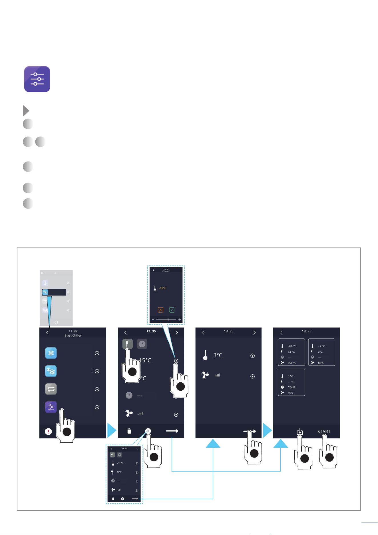
Fig. 20
3
33
Customized cycle
The customized cycle function allows you to set a cycle consisting of a maximum of 3 blast chilling/deep freezing phases plus
a storage phase. The phases can all be with needle probe, all timed or mixed.
To start a saved customized cycle, access the “Recipe book” - “my recipes” section, select its name and press the “start” button.
Fig. 20
1
Select the "customized cycle" function: the 1
st
phase of the cycle appears.
2 3
Touch the “probe” or “clock” symbol to select blast chilling with the needle probe (ends when the probe detects the set
temperature) or timed (ends at the end of the set time).
Make the desired changes as explained in chapt. “Modifying a cycle parameters” on page 31.
4
If you want to add other phases, touch the “add” symbol and modify them as you did for the 1st phase. To pass to the setting of
the storage phase from the 3rd phase, it is necessary to touch the “summary” key.
5
Touch the “summary” key: a summary of all the set phases is displayed.
6
It is now possible to save the set cycle or to start it pressing the “start” key: in this last case the settings made will not be saved.
The saved customized cycles are found in the “Recipe book” - “my recipes” section.
Freezing -18°C
Blast chiller
Blast chilling+3°C
Pre-Cooling
Continuous
Special Cycles
Customized
alarm description
Recipe book
MAINTENANCE
PHASE 1
PHASE 3
min
min min
min
Summary
Phase 1
Phase 3
Phase 2
1
2
3
4
5
6a
6b
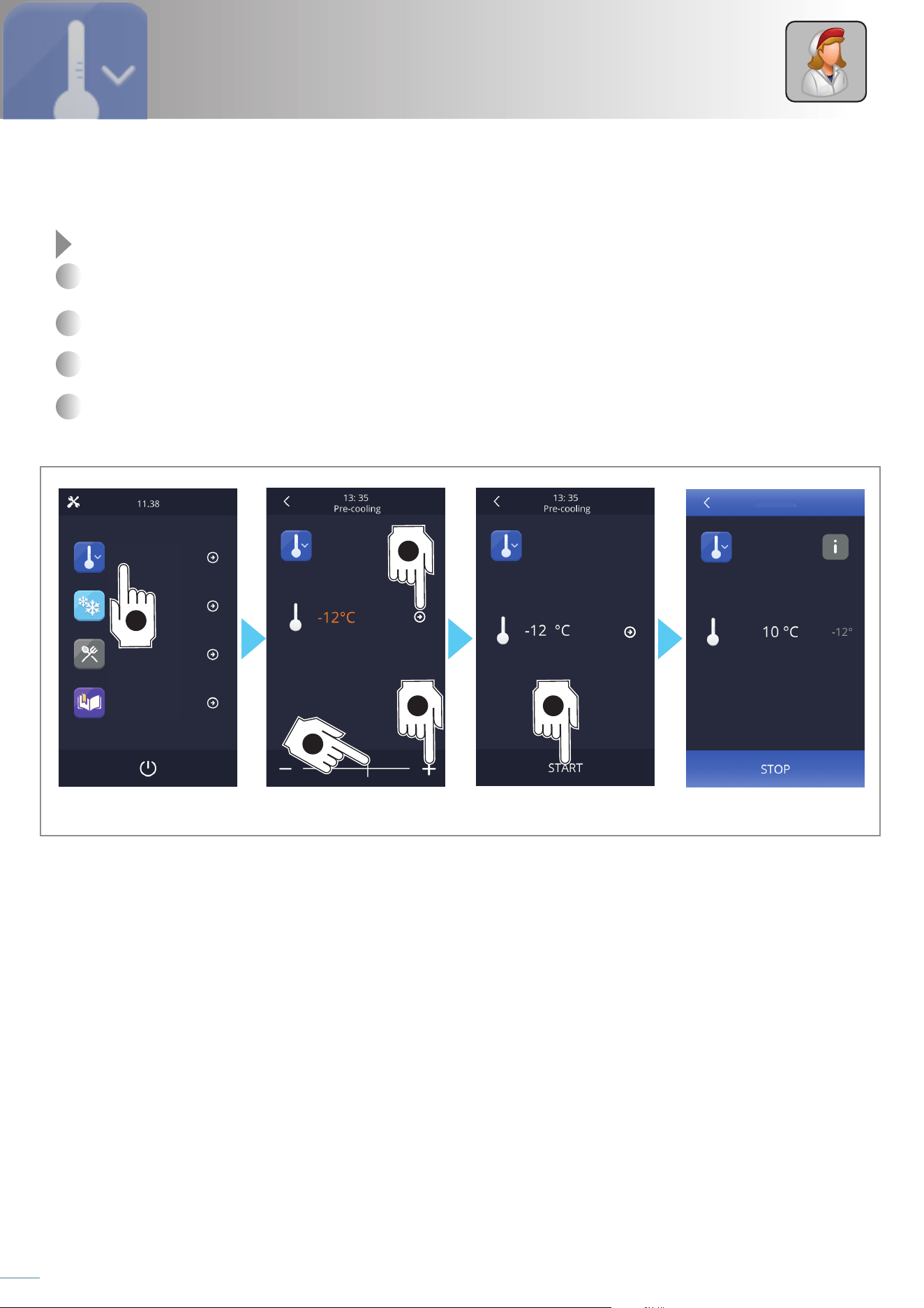
Fig. 21
ABBATTITORE
34
Service
With this section it is possible to select a cell pre-cooling cycle: in this way the foods will be blast chilled/deep frozen in faster times
and with better results.
Pre-cooling is a cycle similar to normal blast chilling, which can precede all operating cycles.
Fig. 21
1
Touch the “pre-cooling” symbol.
2
Act on the symbols “+” or “-” or drag the cursor to enter the desired value within the expected range.
3
To proceed, touch the temperature displayed on the screen or the arrow on the side.
4
Touch
“start”
to start the procedure.
Pre-cooling
Blast chiller
Pre-Cooling
Special Cycles
Recipe book
In progress ...
4
1
3
2b
2a

35
Personal notes
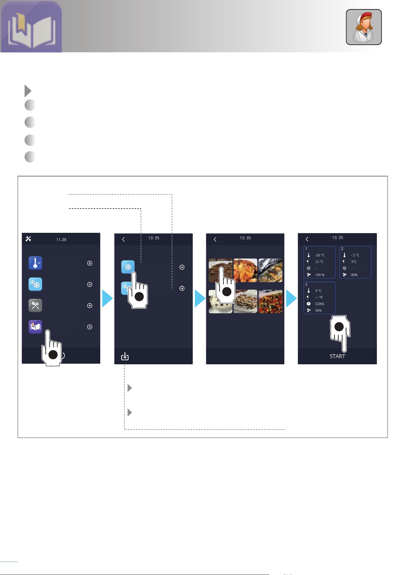
Fig. 22
36
Service
This section contains all the recipes, both those set at the factory and the user's personal ones.
Fig. 22
1
Touch the “recipe book” symbol.
2
Choose the section where the recipe you want to use is (blast chilling, deep freezing, my recipes).
3
Choose the type of recipe you want.
4
Start the recipe pressing the “start” k ey.
Recipe book
FREEZING recipes
User recipes saved setting the cycle parameters.
See chapt. “Saving a cycle with the desired parameters”
on page 30
See chapt. “Customized cycle” on page 33
BLAST CHILLING recipes
Blast chiller
Blast chilling
Freezing
My recipes
Pre-Cooling
Special Cycles
Recipe book
White meat White meat
Lasagne VegetablesCreams
Prodotti Ittici
min min
Recipe book
Blast chilling
Red meat
1
2
3
4
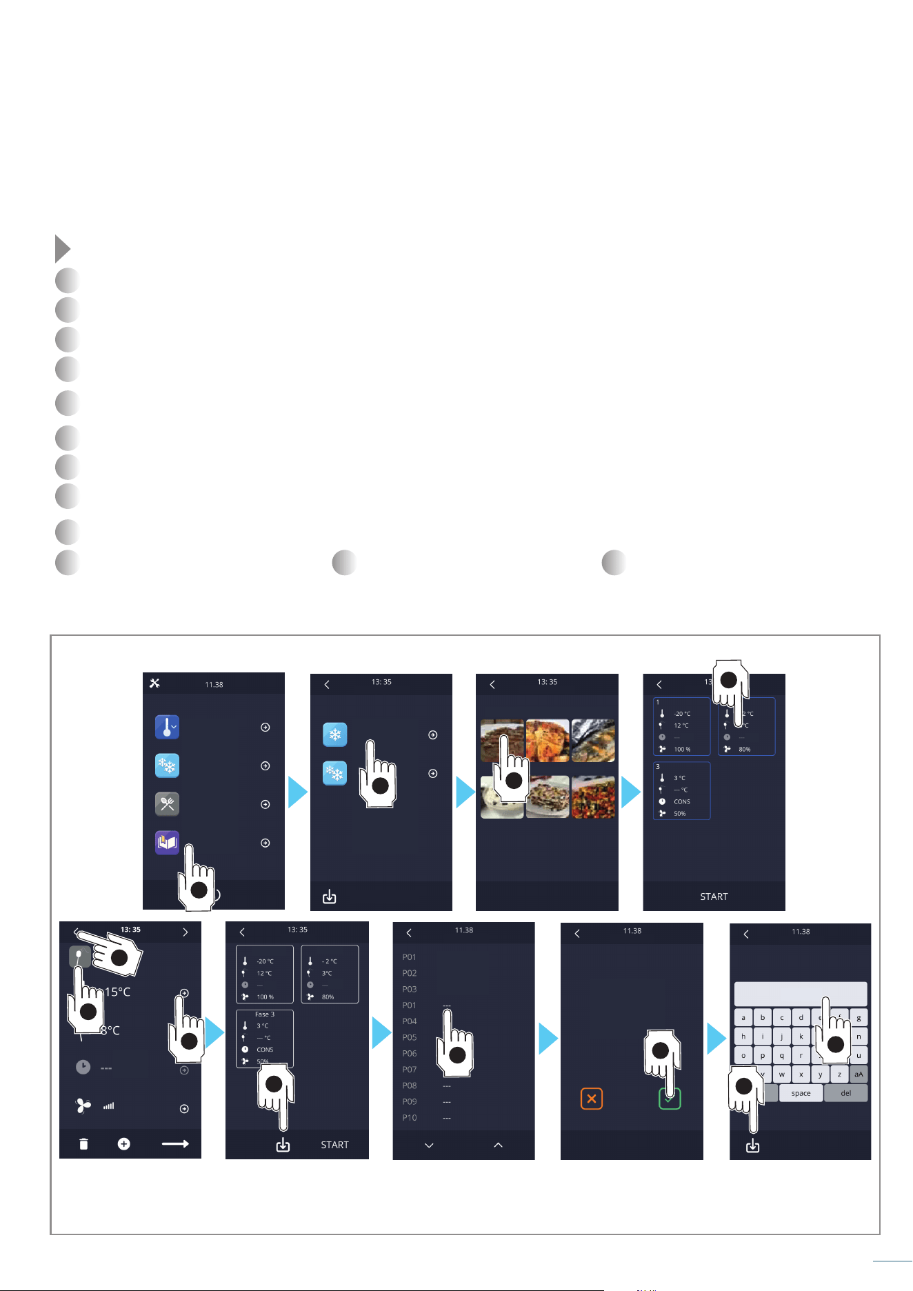
Fig. 23
37
Modifying a recipe and saving it with another name
It is possible to modify an already stored recipe and store it with a new name and with the new settings (the original recipe is not
deleted or modified).
Fig. 23
1
Touch the “recipe book” symbol.
2
Choose the section where the recipe you want to modify is located (blast chilling, deep freezing, my recipes).
3
Choose the type of recipe you want.
4
Touch the phase to be changed (in the example we want to change the parameters of PHASE 2).
5
Touch the “probe” or “clock” symbol to select blast chilling with the needle probe (ends when the probe detects the set temperature)
or timed (ends at the end of the set time).
6
Make the desired changes as explained in chapt. “Modifying a cycle parameters” on page 31.
7
Press the “<” symbol.
8
Make further changes in other phases or touch the “save” key.
9
Touch the position where you want to save the modified recipe. If you select a position already occupied, a screen appears asking
for confirmation before overwriting the recipe.
10
Touch “√” to confirm the entered name.
11
Enter the desired name and touch and
12
confirm the entered name.
Blast chilling
Freezing
My recipes
Blast chiller
Pre-Cooling
Special Cycles
Recipe book
Recipe book
Blast chilling
Red meat
White meat White meat
Lasagne Vegetables
Creams
Fish
PHASE 1
Summary
Save recipe
chicken
lasagne
roastbeef
Save recipe
Save recipe
Recipe name
Roast
Phase 1
Phase 3
Phase 2
min
min
min min
min
1
2
3
9
6
5
4
8
10
12
11
7
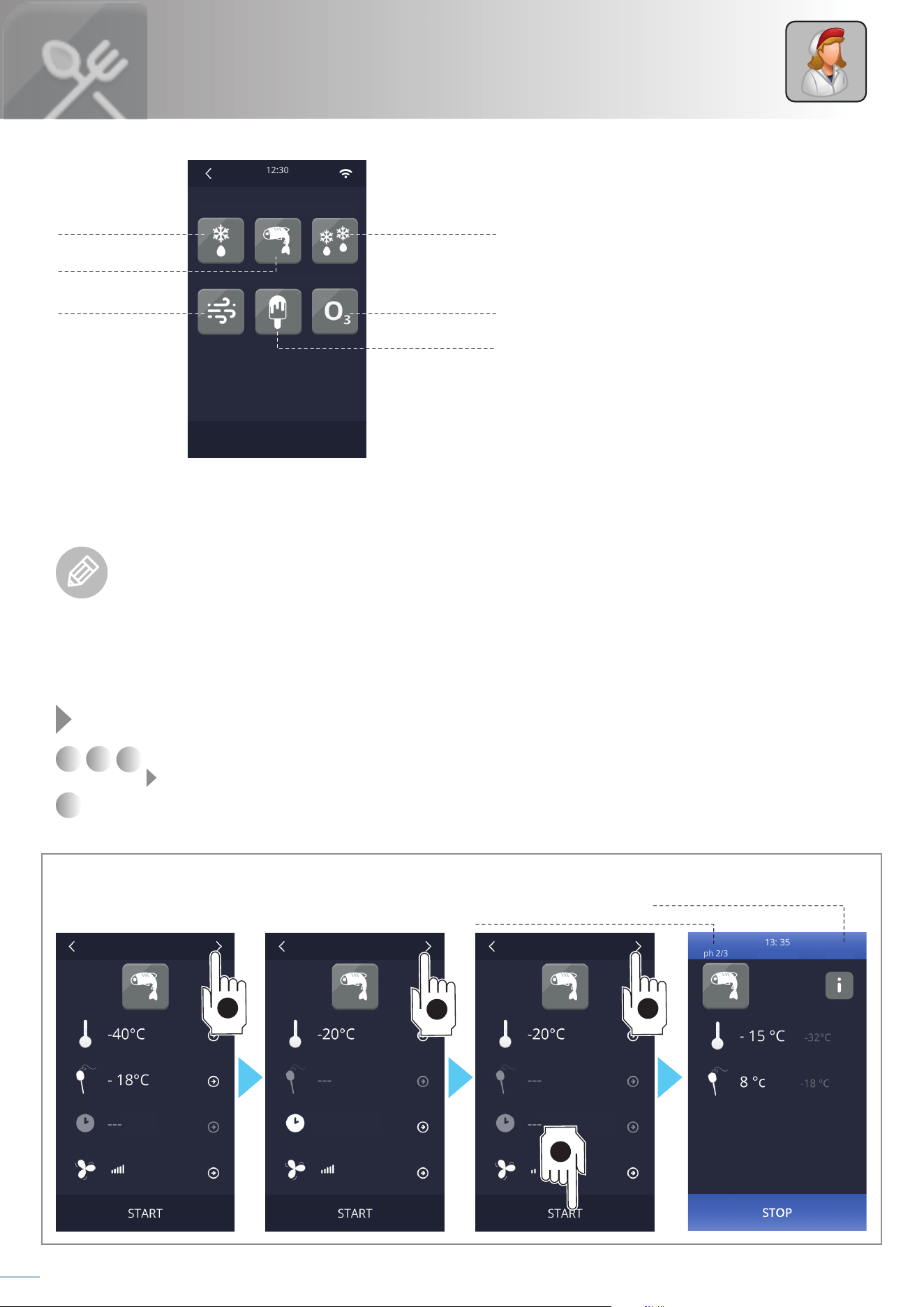
Fig. 24
38
Service
Fish sanitization
Sanitizing fish products is very important as this procedure guarantees the inhibition of the Anisakis simplex bacteria which could be
present in raw or cooked fish.
Anisakiasis is a parasitic infection of the gastrointestinal tract caused by the ingestion of raw or undercooked fish products
containing the larvae of Anisakis simplex: if the larvae penetrate the gastric mucosa they cause violent abdominal pain, nausea
and vomiting. If, a week or two after the infection, they manage to pass into the intestine, an important immune response can
occur, with intermittent abdominal pain, nausea, diarrhoea and fever or intestinal perforation.
The sanitization cycle begins with a blast chilling phase: when the temperature detected by the needle probe reaches the end of
blast chilling temperature, the device will automatically go to the next phase, maintenance.
Once the time set for maintenance has elapsed, the device automatically switches to storage.
Fig. 24
1
2
3
Pressing the “>” symbol several times, the parameters of all three phases that can be changed can be viewed
see chapt. “Modifying a cycle parameters” on page 31.
4
Start the sanitization pressing the “start” k ey.
If necessary, it is possible to block the cycle before its end by pressing the "stop" button:
In this section you have access to special cycles that
facilitate normal work operations.
Special cycles
fish sanitization
thawing
sterilizationdrying
defrosting
ice cream
hardening
current phase:
1/3: blast chilling
2/3: maintenance
3/3 storage
time remaining at the end of
the current phase
blast chilling maintenance
Fish sanitization Fish sanitization
min 240 min
Thawing
Drying
Fish sanitization
Ice cream hardening
Defrosting
Needle heating
Special
1
2
3
4
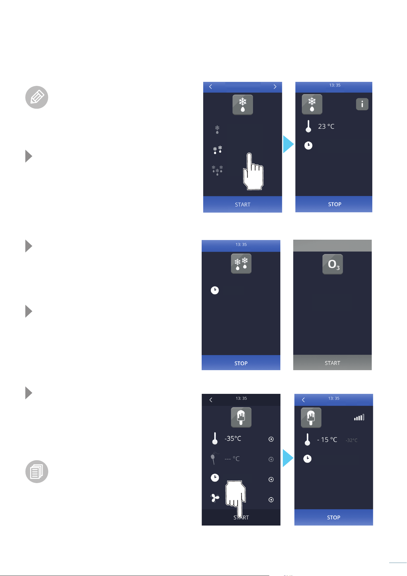
Fig. 25
Fig. 26
Fig. 27
Fig. 28
39
Thawing
The thawing function allows you to bring frozen
products back to a positive temperature in a
controlled and very rapid manner, in compliance
with HACCP standards. This translates into a lower
bacterial load and subsequent better cooking of the thawed
food as
the possibility of having parts of the food not fully
cooked is reduced.
Fig. 25
Thawing is managed by the equipment based on the load of
the equipment you intend to do: low, medium, high (maximum
quantity declared by the manufacturer).
Once the thawing cycle is finished, an acoustic signal is
emitted and the conservation phase starts which, if not
interrupted, lasts indefinitely.
Defrosting
Fig. 26
Defrosting is carried out automatically at regular intervals but,
if necessary, with this function it is possible to start a manual
defrosting cycle.
Sterilization
Fig. 27
The function starts a sterilization cycle of the cell, as long as
the door is closed and the needle probe detects a temperature
higher than 0°C.
The display, for the entire duration of the function, shows the
time left to the end (signalled by an acoustic signal).
Ice cream hardening
Fig. 28
The function allows a freezing cycle particularly suitable for
hardening the mass of ice cream.
The hardening cycle, at the end of the set time, does not
provide for a conservation phase but has an infinite duration
which must be blocked by pressing the "stop" button. The
end of the time is however signalled by an acoustic signal.
It is possible to change the cycle parameters as
explained in the chapt. “Modifying a cycle
parameters” on page 31.
Drying
The function starts a drying cycle by means of ventilation.
The function is interrupted when the time runs out or by
pressing the "stop" key.
IN PROGRESS
IN PROGRESS
Ice cream hardening
STERILIZATION
Press START
to begin
IN PROGRESS
Low load
Medium load
High load
Product quantity
THAWING
32 min
9 min
3 min
134 min
15 min
15 min
240 min
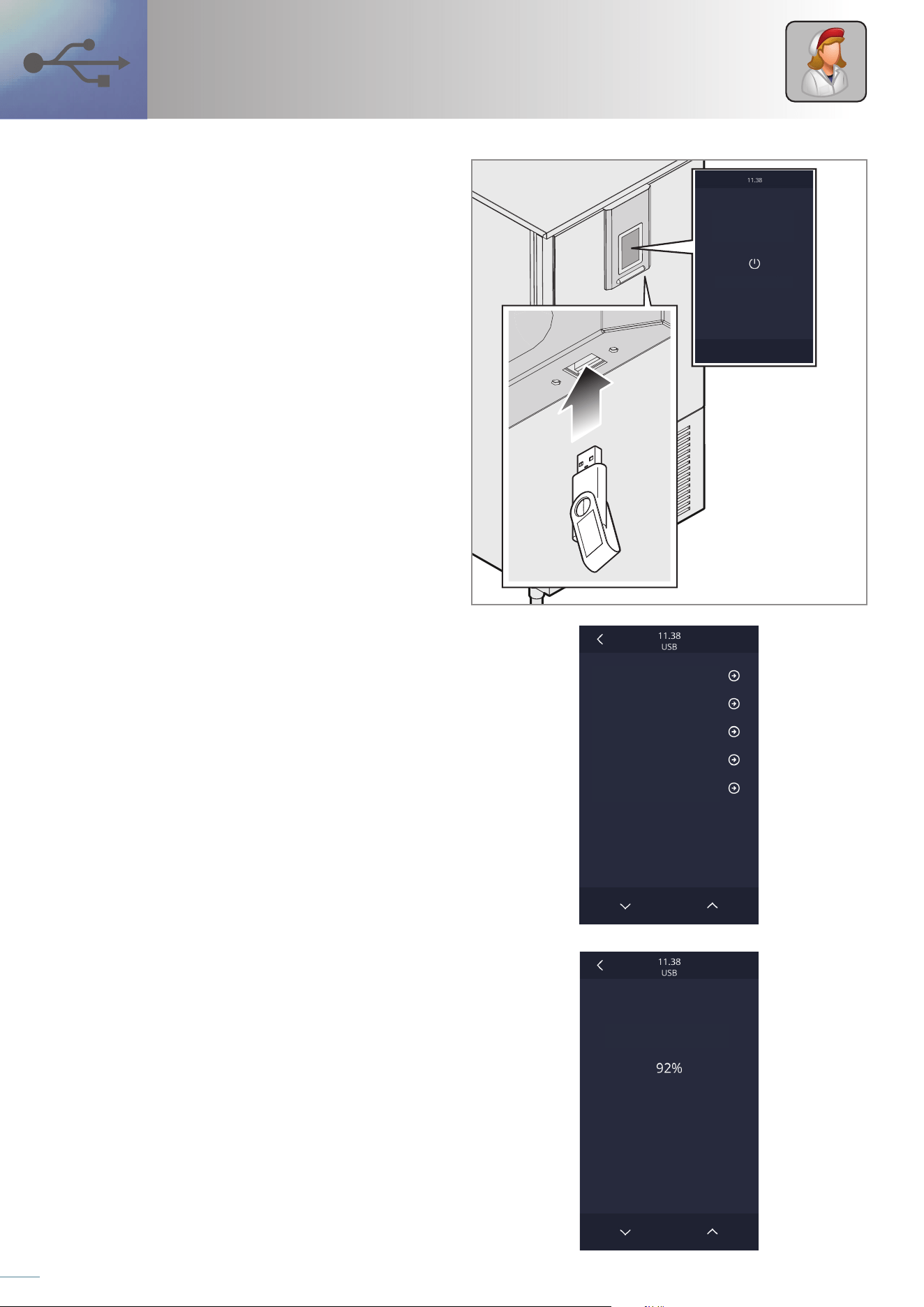
Fig. 29
Fig. 30
Fig. 31
40
Service
USB
The following operations can be performed through the USB
port:
- downloading and uploading recipes;
- downloading and uploading configuration parameters;
- downloading information related to HACCP history.
To access these functions, turn off the panel and connect the
USB stick to the port (Fig. 29).
The screen will be displayed Fig. 30
Recipe download/upload
Connect the USB stick and select “download recipes” or “upload
recipes”: the requested procedure will be automatically started;
the writing/reading operation can take a few minutes.
When finished, remove the USB stick from the serial port.
Parameter download/upload
Connect the USB stick and select “download parameters” or “upload
parameters”: the requested procedure will be automatically
started; the writing/reading operation can take a few minutes.
When finished, remove the USB stick from the serial port.
Parameter download/upload
Connect the USB stick and select “download Haccp data”: a
screen appears where you can select the start date and time
of the log recording (touch day/month/year/time which turns
green and can therefore be edited using the “+” and “–” keys to
get the desired value).
Once confirmed, a CSV (Comma Separated Values) document
will be automatically written onto the stick.
The writing operation can take a few seconds; at the end of the
operation, remove the USB stick from the USB serial port.
press to switch on
DOWNLOAD RECIPES
DOWNLOAD RECIPES
DOWNLOAD PARAMETERS
DOWNLOAD HACCP DATA
UPLOAD PARAMETERS
UPLOAD RECIPES

41
Personal notes
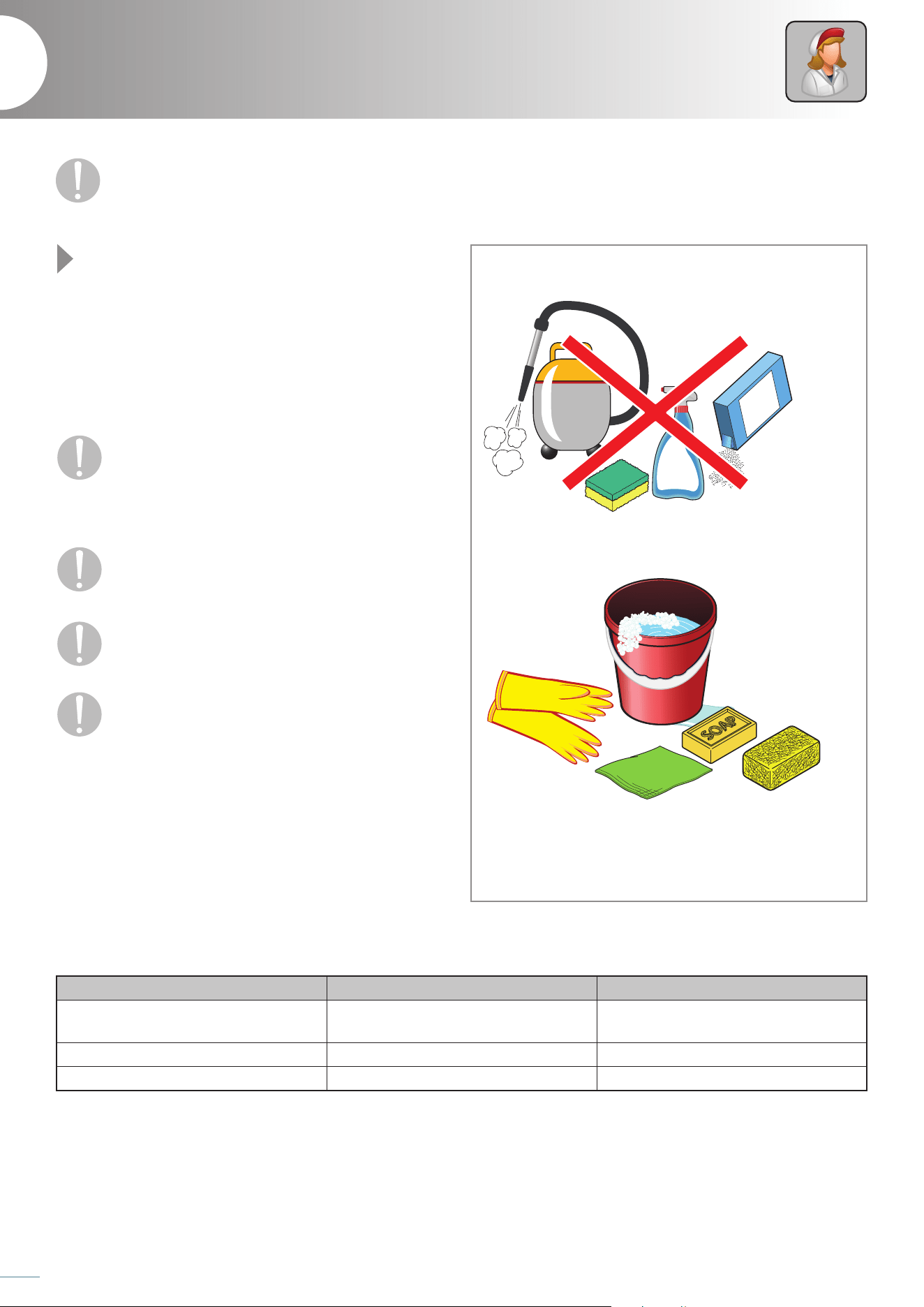
42
Service
Ordinary maintenance
8
Fig. 32
The only maintenance by the operator is the ordinary
cleaning of the equipment. The manufacturer must be
contacted for any anomaly or doubt encountered during
the cleaning operations not described in this manual. For
extraordinary maintenance (e.g. replacement of damaged
parts, repairs, etc...) contact a Service Centre requesting the
intervention of an authorized technician.
Any cleaning operation must be carried out only after
switching the appliance o by acting on the display
and disconnecting the plug: any operation per-
formed on the machine with the electrical system on can cause
serious accidents, even fatal, to people.
Any cleaning operation must be carried out after
wearing appropriate personal protective
equipment (e.g. gloves, etc ...).
The manufacturer does not accept any warranty
damage that is the result of lack of maintenance or
incorrect cleaning (e.g. use of unsuitable detergents).
To clean any part of the equipment DO NOT use:
- abrasive or powder detergents;
- aggressive or corrosive detergents (e.g. hydrochloric/muriatic
or sulphuric acid, caustic soda, etc ...). Attention! Do not use
these substances even to clean the floor under the appliance;
- abrasive or pointed tools (e.g. abrasive sponges, scrapers, steel
brushes, etc ...);
- jets of steam or pressurized water.
Scheduling the cleaning
Before carrying out any ordinary maintenance, it is mandatory to read the safety warnings on
the rst pages of this booklet.
H2O
ACID
OK!
Fig. 32
COMPONENT WHEN TO CLEAN ... HOW TO CLEAN ...
Internal cell and external parts
as required, according to the frequency of
use
see page 43
Condenser every 30 days maximum see page 43
Needle probe after every cycle see page 44
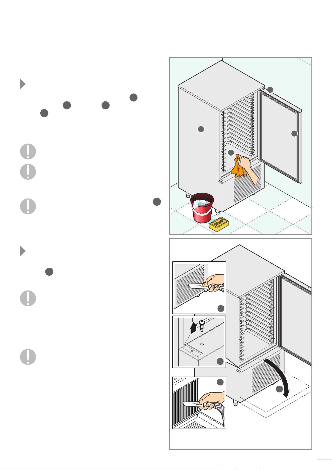
43
Cleaning the internal cell and
external parts
Fig. 33
Carefully clean the internal part of the cell
1
, the door
closing surface
2
, the seal
3
and the appliance
exterior
4
using a soft cloth slightly soaked in soapy water.
After cleaning, rinse with a soft cloth slightly soaked in water and
dry carefully.
Proper internal cleaning of the equipment prevents the
formation of bad odours that could damage the final product.
Do not clean with abrasive tools or cloths that could
release fibres.
The only detergent allowed is soapy water: the use of
different products can cause damage to the surfaces of
the appliance and compromise the quality and
wholesomeness of the food that has been blast chilled.
Pay particular attention to cleaning the display
5
:
clean it with a very soft cloth slightly moistened with
neutral and delicate detergent, suitable for crystal.
Follow the detergent manufacturer's directions for use.
Cleaning the condenser
Fig. 34
For the correct and efficient operation of the equipment, the
condenser
6
must be kept clean to allow the free circulation
of air: this operation must be done every 30 days maximum.
The condenser has sharp edges. During the operations
described below, always wear protective gloves,
goggles and respiratory protection.
Clean the condenser with a soft brush or, preferably, with a
vacuum cleaner to avoid dispersing the dust in the environment.
If there are greasy deposits, remove them using a brush soaked
in alcohol.
Do not scrape the fins with sharp or abrasive bodies.
1
2
3
4
H2O
1
3
4
2
x2
Fig. 33
Fig. 34
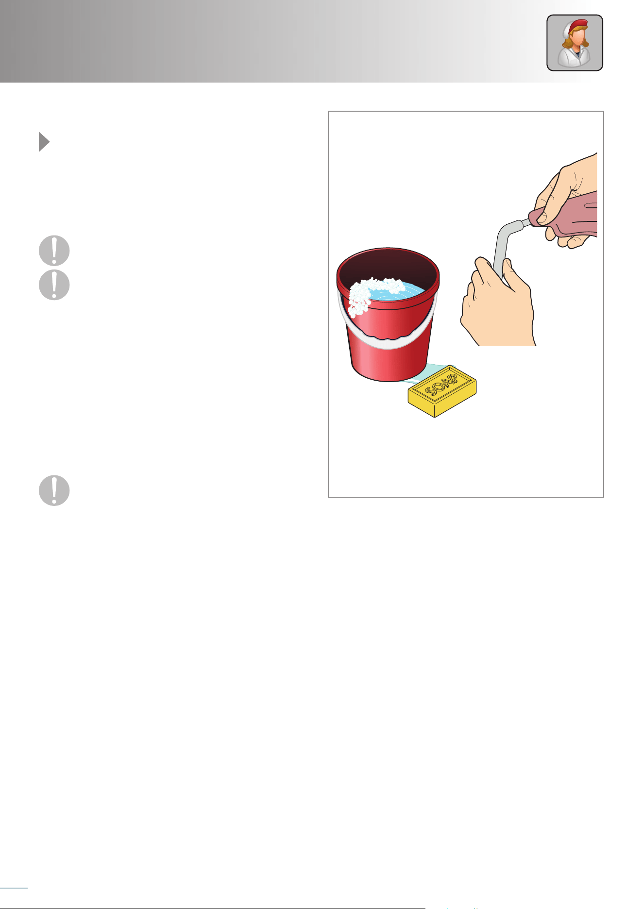
44
Service
Cleaning the needle probe
Fig. 35
Before starting a new cycle, in order to avoid any type of product
"pollution", it is necessary to clean the needle probe.
Remove any type of residue using a soft cloth soaked in neutral
detergent. Rinse thoroughly and treat with a sanitizing product.
Avoid pulling the probe cable: risk of damage.
The probe has a particularly pointed tip. During
cleaning, always wear protective gloves and pay close
attention.
Downtime
During periods of inactivity, disconnect the power supply, and
protect the external steel parts of the equipment by dusting
them with a soft cloth just soaked with Vaseline oil.
Leave the door ajar in order to ensure proper air exchange.
On restarting, before use:
- clean the appliance thoroughly;
- reconnect the appliance to the power supply;
- check the appliance before using it again.
To make sure that the appliance is in perfect
conditions of use and safety, we recommend that
you have it serviced and checked at least once a
year by an authorized service centre.
H2O
OK!
Fig. 35
45
Disposal
To avoid any unauthorized use and the risks associated with it before disposing of the equipment:
- make sure that it is no longer possible to use it: for this purpose, the power supply cable must be cut or removed
(with the appliance disconnected from the mains).
- ensure that no child can accidentally become trapped inside the blast chilling chamber while playing, to this end block the
door opening (for example with adhesive tape or latches).
The appliance is built with ferrous materials, electronic components and plastic. If it is necessary to dispose of it, separate the
different components according to the material they are made of, in order to simplify the differentiated disposal or any reuse
of the parts. Entrust the scrapping to appropriate disposal companies or, in the cases provided by law, return it to the dealer.
For scrapping, always refer to the laws in force in the country of use.
Pay attention that the equipment contains refrigerant gas whose control and recovery must be treated according
to the provisions of the regulations in force in the country of disposal.
The equipment must be disposed of separately from municipal waste.
Pursuant to art. 13 of Legislative Decree No. 49 of 2014 "Implementation of the WEEE Directive 2012/19/EU on waste electri-
cal and electronic equipment", the crossed-out wheeled bin mark means that the product was placed on the market after 13
August 2005 and that at the end of its useful life it must not be treated as other waste but must be disposed of separately. All
the appliances are made of recyclable metal materials (stainless steel, iron, aluminium, galvanized sheet metal, copper, etc.)
in a percentage greater than 90% by weight.
It is necessary to pay attention to the management of this product at the end of its life by reducing any negative impacts on the en-
vironment and improving the efficiency of the use of resources, applying the principles of "polluter pays", prevention, preparation for
reuse, recycling and recovery. Please note that the illegal or incorrect disposal of the product entails the application of the penalties
provided for by current legislation.
Information on disposal in Italy
In Italy WEEE equipment must be delivered to:
- Collection Centres (also called ecological islands or ecological platforms)
- the dealer where you buy new equipment, who is required to accept it free of charge ("one on one" collection).
Information on disposal in European Union countries
The EU WEEE equipment directive has been adopted differently by each country, therefore if you want to dispose of this equipment
we suggest you contact the local authorities or the dealer to ask for the correct method of disposal.
46
Service
Your machine is reliable and robust but sometimes small problems can arise which, thanks to our Service Centres, will be promptly
resolved.
In case of problems, carry out the following procedure:
1
Check for error messages on the display. Try to solve them by consulting the “SOLUTION”, column, if it suggests you contact
an Authorized Service Centre, do it.
2
The problem cannot be solved by the user, it is necessary to contact an Authorized Service Centre.
Fig. 36 Before doing so, record the machine data, the date and the number of the equipment purchase invoice, the codes
of any alarms shown on the display:
serial number .............................................................................................................................................
invoice date .................................................................................................................................................
invoice number ........................................................................................................................................
alarm code ...................................................................................................................................................
If there is a need to send the equipment or parts to a Service Centre or to the Manufacturer (after asking for prior
authorization from the same), the ORIGINAL packaging must be used. If it was not kept, use your own packaging, taking
care that the equipment does not suffer further damage during transport; we recommend writing "FRAGILE-DO NOT TURN
UPSIDE DOWN" on the outside of the packaging.
Do not attempt to repair the equipment yourself, this could cause serious damage to people, animals and property
and voids the Warranty. Request the intervention of an Authorized Service Centre and ask for ORIGINAL spare parts. Failure
to comply with this prescription will void the Warranty.
Warranty
The warranty on the components of the equipment, starting from the date shown on the delivery note, is as per the sales contract.
The Warranty does not cover any damage to the equipment caused by:
- transport and/or handling;
- operator errors;
- lack of maintenance provided for in this manual;
- breakdowns and/or failures not attributable to the equipment malfunction;
- maintenance operations carried out by unqualified personnel;
- misuse.
After-sales service
9
Manufacturer’s details
GEMM srl
Via del Lavoro, 37 - Loc. Cimavilla - 31013 CODOGNE’ (TV) - ITALY
T. +39 0438 778504 – F. +39 0438 470249
e-mail: [email protected] - www.gemm-srl.com
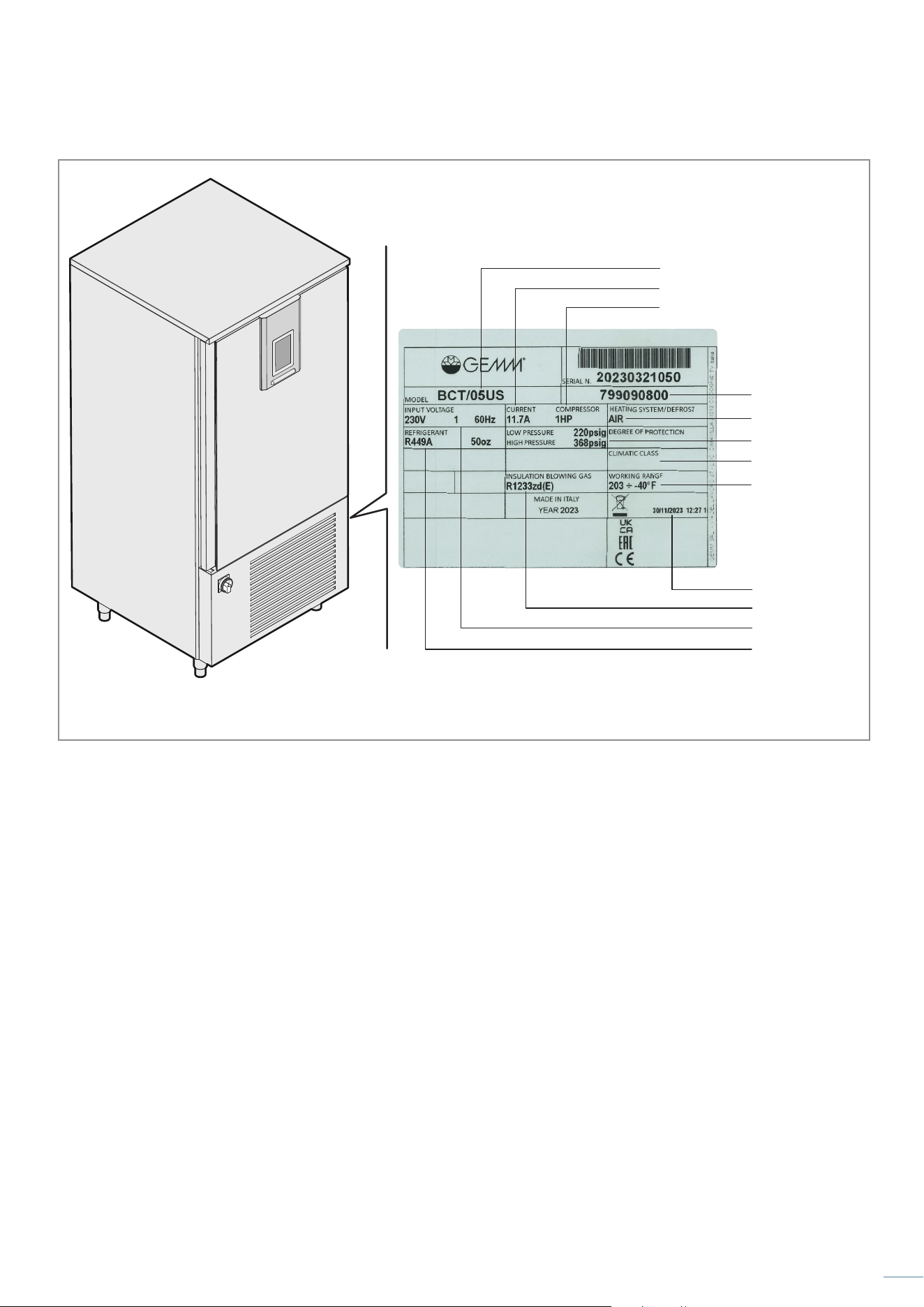
47
Model
Working pressure
Climatic class
Absorbed current
Compressor Power
Type of defrost
Serial number
Working range
Blowing agent
Voltage
Refrigerant type
and quantity
Date of production
dd/mm/yyyy
Production time
hh/mm/ss
Fig. 36
48
ALARM CAUSE SOLUTION
RTC
Clock error:
- the device will not store the date and time when an HACCP
alarm occurs
Set the actual day and time again.
CELL PROBE
Cell probe error:
- if the error occurs during the “stand-by”, you will not be able
to select or start any operating cycle
- if the error occurs during blast chilling or deep freezing,
the cycle continues and the compressor runs continuously
- if the error occurs during storage, the compressor's activity
will depend on parameters C4 and C5 or C9
- if the error occurs during leavening, slow cooking or a
thawing cycle, the cycle is interrupted
Contact an Authorized Service
Centre
EVAPORATOR PROBE Evaporator probe error
CONDENSER PROBE Condenser probe error
NEEDLE 1/2/3 SENSOR
Needle probe error, the equipment will use any other available
probes
- if the error occurs during the “stand-by”, the operating cycles
with the needle probe will start as timed
- if the error occurs during temperature blast chilling, blast
chilling will last according to the time set with parameter r1
- if the error occurs during temperature freezing, freezing will
last according to the time set with parameter r1
- if the error occurs during the heating of the needle probe,
heating will be interrupted
THERMAL
Thermal protection alarm:
the current cycle is always interrupted
HIGH/LOW
PRESSURE
High/low pressure alarm: if the cycle in progress uses the
compressor, the cycle is interrupted.
HIGH/LOW
PRESSURE
Maximum or minimum temperature alarm (HACCP):
- the device will store the alarm
DOOR OPEN The door is open Close the door
CYCLE DURATION
Positive or negative blast chilling has not been completed
within the maximum factory-set time (HACCP error):
- the device will store the alarm
The blast chiller has probably been
excessively or incorrectly loaded, try
to perform a new cycle with smaller
quantities. If the problem persists,
contact an Authorized Service Centre
BASIC COMMUNICATION
User-control module interface communication error:
- any cycle in progress will be terminated and it will not be
possible to start one.
Contact an Authorized Service Cen-
tre BASIC COMPATIBILITY
User-control module interface compatibility error:
- any cycle in progress will be terminated and it will not be
possible to start one.
NEEDLE
Needle probe alarm (all enabled needle probes are in alarm):
- any timed cycle will be interrupted
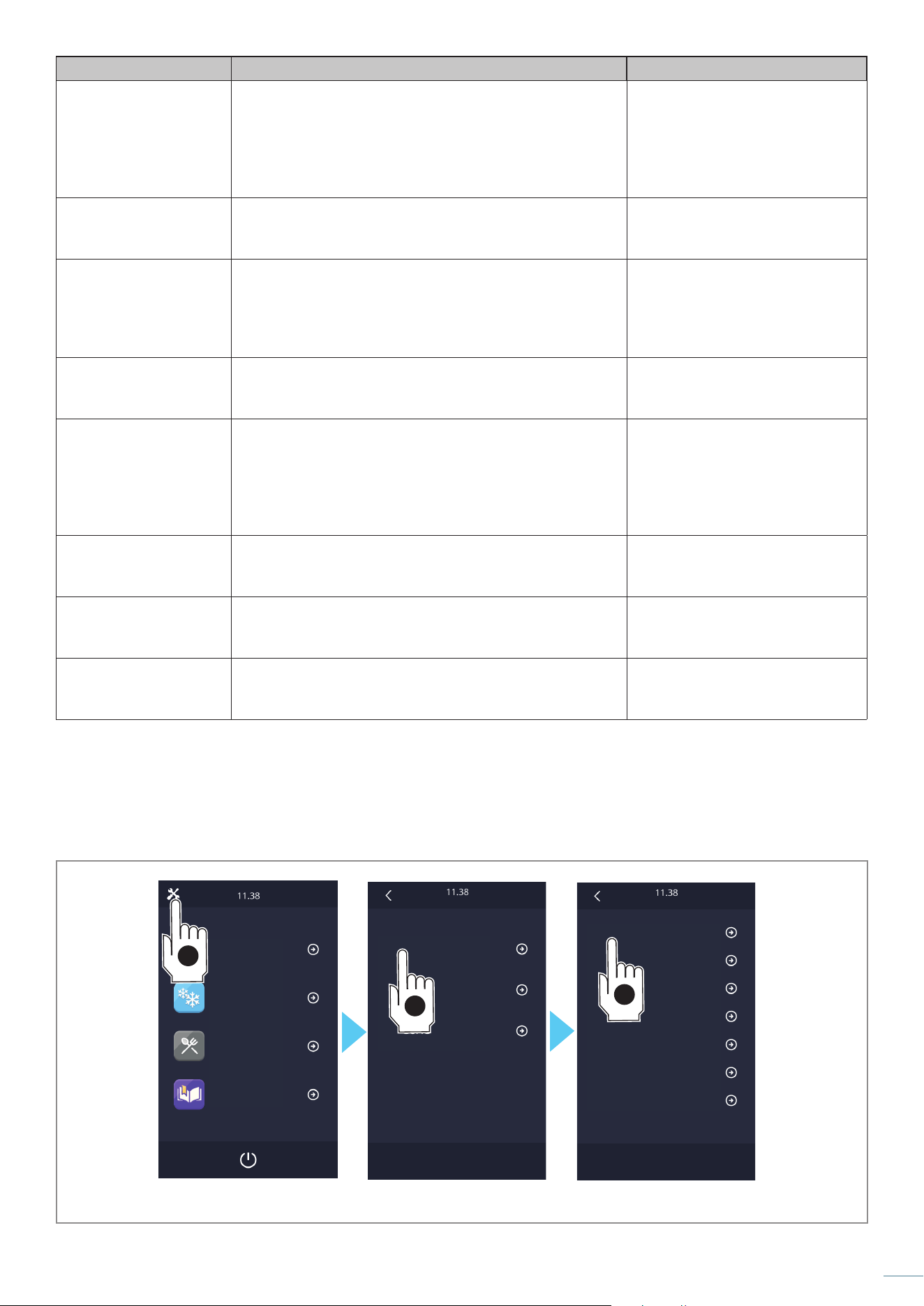
49
ALARM CAUSE SOLUTION
POWER FAILURE
Power supply interruption alarm:
- the device will store the alarm
- the cycle in progress will restart when the power is reset
- The alarm output will be activated
Check that the power supply has not
been cut off (e.g. black-out), that the
plug is correctly inserted and that
the power cable is not damaged.
If the problem persists, contact an
Authorized Service Centre
SANITIZATION NEEDLE
INSERTION
Sanitization alarm:
- The sanitization cycle will be interrupted
Check the needle probe is inserted
correctly. If the problem persists,
contact an Authorized Service Centre
SANITIZATION DURATION
Sanitization not completed within the expected maximum
duration (HACCP alarm):
- the device will store the alarm
- the current cycle will be interrupted
- the alarm output will be activated.
OVERHEATED COND.
Overheated condenser alarm.
- The condenser fan will be turned on
- the alarm output will be activated.
BLOCKED COMP.
Blocked compressor alarm:
- if the error occurs during the "stand-by" status, you will not be
able to select or start any operating cycle
- if the error occurs during an operating cycle, the cycle will be
interrupted
- the alarm output will be activated.
NEEDLE INSERTION
Needle not inserted alarm:
- The temperature cycle in progress is changed into a timed
cycle
Check the needle probe is inserted
correctly. If the problem persists,
contact an Authorized Service Centre
EXPANSION
COMMUNICATION
User-expansion module interface communication error:
- any leavening or slow-cooking cycle in progress will be
terminated and it will not be possible to start one.
EXPANSION
COMPATIBILITY
User-expansion module interface communication error
- any cycle in progress will be terminated and it will not be
possible to start one.
Fig. 37
Blast chiller
Settings
Pre-Cooling
Special Cycles
Recipe book
INPUT AND OUTPUT STATUS
OPER. HOURS COMPRESSOR
DATE/TIME SETTING
HACCP DATA SELECTION
RESET OPER. HOURS COMPR
HACCP ALARM RESET
ALARMS
SERVICE
SETUP
LANGUAGE SELECTION
3
1
2

Personal notes

Personal notes

INSTRUCTIONS
FOR USE
BLAST-CHILLER
“NEW RUNNER” Series
FULL TOUCH Control Panel
BCT/05 US
BCT/10 US
BCT/15 US
Manual BCT US - Rev. 03-2026
G
G
E
E
M
M
M
M
s
s
r
r
l
l
Via del Lavoro, 37 - Loc. Cimavilla - 31013 CODOGNE' (TV) -
ITALY
T. +39 0438 778504 – F. +39 0438 470249
e-mail: info@gemm -srl.com - www.gemm- srl.com
Iscr.Reg.Impr. TV - CF e P. IVA 03441880261 - REA TV 272556
Registro Prod. AEE-TV n IT08020000001108
G
G
E
E
M
M
M
M
s
s
r
r
l
l
Via del Lavoro, 37 - Loc. Cimavilla - 31013 CODOGNE' (TV) -
ITALY
T. +39 0438 778504 – F. +39 0438 470249
e-mail: info@gemm -srl.com - www.gemm- srl.com
Iscr.Reg.Impr. TV - CF e P. IVA 03441880261 - REA TV 272556
Registro Prod. AEE-TV n IT08020000001108
G
G
E
E
M
M
M
M
s
s
r
r
l
l
Via del Lavoro, 37 - Loc. Cimavilla - 31013 CODOGNE' (TV) -
ITALY
T. +39 0438 778504 – F. +39 0438 470249
e-mail: info@gemm -srl.com - www.gemm- srl.com
Iscr.Reg.Impr. TV - CF e P. IVA 03441880261 - REA TV 272556
Registro Prod. AEE-TV n IT08020000001108
G
G
E
E
M
M
M
M
s
s
r
r
l
l
Via del Lavoro, 37 - Loc. Cimavilla - 31013 CODOGNE' (TV) -
ITALY
T. +39 0438 778504 – F. +39 0438 470249
e-mail: info@gemm -srl.com - www.gemm- srl.com
Iscr.Reg.Impr. TV - CF e P. IVA 03441880261 - REA TV 272556
Registro Prod. AEE-TV n IT08020000001108